mbe family (lan ranger series) - bestdatasource.com · mbe family (lan ranger series) ethernet...
TRANSCRIPT
MBE Family (LAN RANger Series)
Installation and Operation Manual
Ethernet Remote Access Routers (MBE10-1, MBE10-8, MBE10-1D, MBE10-8D)
Order from: Cutter Networks Ph:727-398-5252/Fax:727-397-9610 www.bestdatasource.com

Order from: Cutter Networks Ph:727-398-5252/Fax:727-397-9610 www.bestdatasource.com

MBE Family (LAN RANger Series) Ethernet Remote Access Routers (MBE10-1, MBE10-8,
MBE10-1D, MBE10-8D) Version 7
Installation and Operation Manual
Notice This manual contains information that is proprietary to RAD Data Communications Ltd. ("RAD"). No part of this publication may be reproduced in any form whatsoever without prior written approval by RAD Data Communications.
Right, title and interest, all information, copyrights, patents, know-how, trade secrets and other intellectual property or other proprietary rights relating to this manual and to the MBE Family (LAN RANger Series) and any software components contained therein are proprietary products of RAD protected under international copyright law and shall be and remain solely with RAD.
MBE Family (LAN RANger Series) is a registered trademark of RAD. No right, license, or interest to such trademark is granted hereunder, and you agree that no such right, license, or interest shall be asserted by you with respect to such trademark.
You shall not copy, reverse compile or reverse assemble all or any portion of the Manual or the MBE Family (LAN RANger Series). You are prohibited from, and shall not, directly or indirectly, develop, market, distribute, license, or sell any product that supports substantially similar functionality as the MBE Family (LAN RANger Series), based on or derived in any way from the MBE Family (LAN RANger Series). Your undertaking in this paragraph shall survive the termination of this Agreement.
This Agreement is effective upon your opening of the MBE Family (LAN RANger Series) package and shall continue until terminated. RAD may terminate this Agreement upon the breach by you of any term hereof. Upon such termination by RAD, you agree to return to RAD the MBE Family (LAN RANger Series) and all copies and portions thereof.
For further information contact RAD at the address below or contact your local distributor.
International Headquarters RAD Data Communications Ltd. 24 Raoul Wallenberg St. Tel Aviv 69719 Israel Tel: 972-3-6458181 Fax: 972-3-6498250 E-mail: [email protected]
U.S. Headquarters RAD Data Communications Inc. 900 Corporate Drive Mahwah, NJ 07430 USA Tel: (201) 529-1100, Toll free: 1-800-444-7234 Fax: (201) 529-5777 E-mail: [email protected]
© 1994-2003 RAD Data Communications Ltd. Publication No. 572-200-02/03
Order from: Cutter Networks Ph:727-398-5252/Fax:727-397-9610 www.bestdatasource.com

Limited Warranty
RAD warrants to DISTRIBUTOR that the hardware in the MBE Family (LAN RANger Series) to be delivered hereunder shall be free of defects in material and workmanship under normal use and service for a period of twelve (12) months following the date of shipment to DISTRIBUTOR.
If, during the warranty period, any component part of the equipment becomes defective by reason of material or workmanship, and DISTRIBUTOR immediately notifies RAD of such defect, RAD shall have the option to choose the appropriate corrective action: a) supply a replacement part, or b) request return of equipment to its plant for repair, or c) perform necessary repair at the equipment's location. In the event that RAD requests the return of equipment, each party shall pay one-way shipping costs.
RAD shall be released from all obligations under its warranty in the event that the equipment has been subjected to misuse, neglect, accident or improper installation, or if repairs or modifications were made by persons other than RAD's own authorized service personnel, unless such repairs by others were made with the written consent of RAD.
The above warranty is in lieu of all other warranties, expressed or implied. There are no warranties which extend beyond the face hereof, including, but not limited to, warranties of merchantability and fitness for a particular purpose, and in no event shall RAD be liable for consequential damages.
RAD shall not be liable to any person for any special or indirect damages, including, but not limited to, lost profits from any cause whatsoever arising from or in any way connected with the manufacture, sale, handling, repair, maintenance or use of the MBE Family (LAN RANger Series), and in no event shall RAD's liability exceed the purchase price of the MBE Family (LAN RANger Series).
DISTRIBUTOR shall be responsible to its customers for any and all warranties which it makes relating to MBE Family (LAN RANger Series) and for ensuring that replacements and other adjustments required in connection with the said warranties are satisfactory.
Software components in the MBE Family (LAN RANger Series) are provided "as is" and without warranty of any kind. RAD disclaims all warranties including the implied warranties of merchantability and fitness for a particular purpose. RAD shall not be liable for any loss of use, interruption of business or indirect, special, incidental or consequential damages of any kind. In spite of the above RAD shall do its best to provide error-free software products and shall offer free Software updates during the warranty period under this Agreement.
RAD's cumulative liability to you or any other party for any loss or damages resulting from any claims, demands, or actions arising out of or relating to this Agreement and the MBE Family (LAN RANger Series) shall not exceed the sum paid to RAD for the purchase of the MBE Family (LAN RANger Series). In no event shall RAD be liable for any indirect, incidental, consequential, special, or exemplary damages or lost profits, even if RAD has been advised of the possibility of such damages.
This Agreement shall be construed and governed in accordance with the laws of the State of Israel.
Order from: Cutter Networks Ph:727-398-5252/Fax:727-397-9610 www.bestdatasource.com

General Safety Instructions The following instructions serve as a general guide for the safe installation and operation of telecommunications products. Additional instructions, if applicable, are included inside the manual.
Safety Symbols
This symbol may appear on the equipment or in the text. It indicates potential safety hazards regarding product operation or maintenance to operator or service personnel.
Danger of electric shock! Avoid any contact with the marked surface while the product is energized or connected to outdoor telecommunication lines.
.
Protective earth: the marked lug or terminal should be connected to the building protective earth bus.
Some products may be equipped with a laser diode. In such cases, a label with the laser class and other warnings as applicable will be attached near the optical transmitter. The laser warning symbol may be also attached. Please observe the following precautions: • Before turning on the equipment, make sure that the fiber optic cable is
intact and is connected to the transmitter. • Do not attempt to adjust the laser drive current. • Do not use broken or unterminated fiber-optic cables/connectors or look
straight at the laser beam. • The use of optical devices with the equipment will increase eye hazard. • Use of controls, adjustments or performing procedures other than those
specified herein, may result in hazardous radiation exposure.
ATTENTION: The laser beam may be invisible!
Always observe standard safety precautions during installation, operation and maintenance of this product. Only qualified and authorized service personnel should carry out adjustment, maintenance or repairs to this product. No installation, adjustment, maintenance or repairs should be performed by either the operator or the user.
Warning
Warning
Order from: Cutter Networks Ph:727-398-5252/Fax:727-397-9610 www.bestdatasource.com

Handling Energized Products General Safety Practices Do not touch or tamper with the power supply when the power cord is connected. Line voltages may be present inside certain products even when the power switch (if installed) is in the OFF position or a fuse is blown. For DC-powered products, although the voltages levels are usually not hazardous, energy hazards may still exist.
Before working on equipment connected to power lines or telecommunication lines, remove jewelry or any other metallic object that may come into contact with energized parts.
Unless otherwise specified, all products are intended to be grounded during normal use. Grounding is provided by connecting the mains plug to a wall socket with a protective earth terminal. If an earth lug is provided on the product, it should be connected to the protective earth at all times, by a wire with a diameter of 18 AWG or wider. Rack-mounted equipment should be mounted only in earthed racks and cabinets.
Always make the ground connection first and disconnect it last. Do not connect telecommunication cables to ungrounded equipment. Make sure that all other cables are disconnected before disconnecting the ground.
Connection of AC Mains Make sure that the electrical installation complies with local codes.
Always connect the AC plug to a wall socket with a protective ground.
The maximum permissible current capability of the branch distribution circuit that supplies power to the product is 16A. The circuit breaker in the building installation should have high breaking capacity and must operate at short-circuit current exceeding 35A.
Always connect the power cord first to the equipment and then to the wall socket. If a power switch is provided in the equipment, set it to the OFF position. If the power cord cannot be readily disconnected in case of emergency, make sure that a readily accessible circuit breaker or emergency switch is installed in the building installation.
Connection of DC Mains Unless otherwise specified in the manual, the DC input to the equipment is floating in reference to the ground. Any single pole can be externally grounded.
Due to the high current capability of DC mains systems, care should be taken when connecting the DC supply to avoid short-circuits and fire hazards.
DC units should be installed in a restricted access area, i.e. an area where access is authorized only to qualified service and maintenance personnel.
Make sure that the DC supply is electrically isolated from any AC source and that the installation complies with the local codes.
The maximum permissible current capability of the branch distribution circuit that supplies power to the product is 16A. The circuit breaker in the building installation should have high breaking capacity and must operate at short-circuit current exceeding 35A.
Before connecting the DC supply wires, ensure that power is removed form the DC circuit. Locate the circuit breaker of the panel board that services the equipment and switch it to the OFF position. When connecting the DC supply wires, first connect the ground wire to the corresponding terminal, then the positive pole and last the negative pole. Switch the circuit breaker back to the ON position.
A readily accessible disconnect device that is suitably rated and approved should be incorporated in the building installation.
Order from: Cutter Networks Ph:727-398-5252/Fax:727-397-9610 www.bestdatasource.com

Connection of Data and Telecommunications Cables Data and telecommunication interfaces are classified according to their safety status.
The following table lists the status of several standard interfaces. If the status of a given port differs from the standard one, a notice will be given in the manual.
Ports Safety Status
V.11, V.28, V.35, V.36, RS-530, X.21, 10 BaseT, 100 BaseT, Unbalanced E1, E2, E3, STM, DS-2, DS-3, S-Interface ISDN, Analog voice E&M
SELV Safety Extra Low Voltage:
Ports which do not present a safety hazard. Usually up to 30 VAC or 60 VDC.
xDSL (without feeding voltage), Balanced E1, T1, Sub E1/T1
TNV-1 Telecommunication Network Voltage-1:
Ports whose normal operating voltage is within the limits of SELV, on which overvoltages from telecommunications networks are possible.
FXS (Foreign Exchange Subscriber) TNV-2 Telecommunication Network Voltage-2:
Ports whose normal operating voltage exceeds the limits of SELV (usually up to 120 VDC or telephone ringing voltages), on which overvoltages from telecommunication networks are not possible. These ports are not permitted to be directly connected to external telephone and data lines.
FXO (Foreign Exchange Office), xDSL (with feeding voltage), U-Interface ISDN
TNV-3 Telecommunication Network Voltage-3:
Ports whose normal operating voltage exceeds the limits of SELV (usually up to 120 VDC or telephone ringing voltages), on which overvoltages from telecommunication networks are possible.
Always connect a given port to a port of the same safety status. If in doubt, seek the assistance of a qualified safety engineer.
Always make sure that the equipment is grounded before connecting telecommunication cables. Do not disconnect the ground connection before disconnecting all telecommunications cables.
Some SELV and non-SELV circuits use the same connectors. Use caution when connecting cables. Extra caution should be exercised during thunderstorms.
When using shielded or coaxial cables, verify that there is a good ground connection at both ends. The earthing and bonding of the ground connections should comply with the local codes.
The telecommunication wiring in the building may be damaged or present a fire hazard in case of contact between exposed external wires and the AC power lines. In order to reduce the risk, there are restrictions on the diameter of wires in the telecom cables, between the equipment and the mating connectors.
Order from: Cutter Networks Ph:727-398-5252/Fax:727-397-9610 www.bestdatasource.com

To reduce the risk of fire, use only No. 26 AWG or larger telecommunication line cords.
Pour réduire les risques s’incendie, utiliser seulement des conducteurs de télécommunications 26 AWG ou de section supérieure.
Some ports are suitable for connection to intra-building or non-exposed wiring or cabling only. In such cases, a notice will be given in the installation instructions.
Do not attempt to tamper with any carrier-provided equipment or connection hardware.
Electromagnetic Compatibility (EMC) The equipment is designed and approved to comply with the electromagnetic regulations of major regulatory bodies. The following instructions may enhance the performance of the equipment and will provide better protection against excessive emission and better immunity against disturbances.
A good earth connection is essential. When installing the equipment in a rack, make sure to remove all traces of paint from the mounting points. Use suitable lock-washers and torque. If an external grounding lug is provided, connect it to the earth bus using braided wire as short as possible.
The equipment is designed to comply with EMC requirements when connecting it with unshielded twisted pair (UTP) cables. However, the use of shielded wires is always recommended, especially for high-rate data. In some cases, when unshielded wires are used, ferrite cores should be installed on certain cables. In such cases, special instructions are provided in the manual.
Disconnect all wires which are not in permanent use, such as cables used for one-time configuration.
The compliance of the equipment with the regulations for conducted emission on the data lines is dependent on the cable quality. The emission is tested for UTP with 80 dB longitudinal conversion loss (LCL).
Unless otherwise specified or described in the manual, TNV-1 and TNV-3 ports provide secondary protection against surges on the data lines. Primary protectors should be provided in the building installation.
The equipment is designed to provide adequate protection against electro-static discharge (ESD). However, it is good working practice to use caution when connecting cables terminated with plastic connectors (without a grounded metal hood, such as flat cables) to sensitive data lines. Before connecting such cables, discharge yourself by touching earth ground or wear an ESD preventive wrist strap.
FCC-15 User Information This equipment has been tested and found to comply with the limits of the Class A digital device, pursuant to Part 15 of the FCC rules. These limits are designed to provide reasonable protection against harmful interference when the equipment is operated in a commercial environment. This equipment generates, uses and can radiate radio frequency energy and, if not installed and used in accordance with the Installation and Operation manual, may cause harmful interference to the radio communications. Operation of this equipment in a residential area is likely to cause harmful interference in which case the user will be required to correct the interference at his own expense.
Caution
Attention
Order from: Cutter Networks Ph:727-398-5252/Fax:727-397-9610 www.bestdatasource.com

Canadian Emission Requirements This Class A digital apparatus meets all the requirements of the Canadian Interference-Causing Equipment Regulation.
Cet appareil numérique de la classe A respecte toutes les exigences du Règlement sur le matériel brouilleur du Canada.
Warning per EN 55022 (CISPR-22)
This is a class A product. In a domestic environment, this product may cause radio interference, in which case the user will be required to take adequate measures.
Cet appareil est un appareil de Classe A. Dans un environnement résidentiel, cet appareil peut provoquer des brouillages radioélectriques. Dans ces cas, il peut être demandé à l’utilisateur de prendre les mesures appropriées.
Dieses ist ein Gerät der Funkstörgrenzwertklasse A. In Wohnbereichen können bei Betrieb dieses Gerätes Rundfunkströrungen auftreten, in welchen Fällen der Benutzer für entsprechende Gegenmaßnahmen verantwortlich ist.
Warning
Avertissement
Achtung
Order from: Cutter Networks Ph:727-398-5252/Fax:727-397-9610 www.bestdatasource.com

Declaration of Conformity Manufacturer's Name: RAD Data Communications Ltd.
Manufacturer's Address: 24 Raoul Wallenberg St. Tel Aviv 69719
Israel declares that the product: Product Name: MBE10-1, MBE10-8, MBE10-1D, MBE10-8D conforms to the following standard(s) or other normative document(s): EMC: EN 55022 (1994) Limits and methods of measurement of radio disturbance
characteristics of information technology equipment. EN 50082-1 (1992) Electromagnetic compatibility - Generic immunity standards
for residential, commercial and light industry. Safety: EN 60950 (1992/93) Safety of information technology equipment, including
electrical business equipment. Supplementary Information: The product herewith complies with the requirements of the EMC Directive 89/336/EEC and the Low Voltage Directive 73/23/EEC. The product was tested in a typical configuration.
Tel Aviv, September 18th, 1996
Haim Karshen VP Quality European Contact: RAD Data Communications GmbH, Otto-Hahn-Str. 28-30, 85521 Ottobrunn-Riemerling, Germany
Order from: Cutter Networks Ph:727-398-5252/Fax:727-397-9610 www.bestdatasource.com

Conventions
A note draws attention to a general rule for a procedure, or to exceptions to a rule.
A caution warns of possible damage to the equipment if a procedure is not followed correctly.
A warning alerts to the presence of important operating and maintenance (servicing) instructions in the literature accompanying the equipment. If these instructions are not followed exactly, possible bodily injury may occur.
Note
Caution
Warning
Order from: Cutter Networks Ph:727-398-5252/Fax:727-397-9610 www.bestdatasource.com

Order from: Cutter Networks Ph:727-398-5252/Fax:727-397-9610 www.bestdatasource.com
MBE Family Installation and Operation Manual i
Contents
Chapter 1. Introduction 1.1 Overview..................................................................................................................... 1-1
General ................................................................................................................................1-1 Versions................................................................................................................................1-1 Applications..........................................................................................................................1-2 Features................................................................................................................................1-2
1.2 Physical Description..................................................................................................... 1-4 1.3 Functional Description................................................................................................. 1-5
General ................................................................................................................................1-5 Principles of Operation .........................................................................................................1-6 Functional Block Diagram .....................................................................................................1-7 Management ........................................................................................................................1-9
1.4 Technical Specifications............................................................................................. 1-10
Chapter 2. Installation 2.1 Introduction................................................................................................................. 2-1 2.2 Site Requirements and Prerequisites ............................................................................ 2-1 2.3 Package Contents ........................................................................................................ 2-2 2.4 Equipment Needed ..................................................................................................... 2-2 2.5 Installation and Setup .................................................................................................. 2-2
Configuring MBE...................................................................................................................2-3 Connecting the Interfaces .....................................................................................................2-7 Connecting the Line..............................................................................................................2-8 Connecting the LAN .............................................................................................................2-8 Connecting the Power ..........................................................................................................2-9
Chapter 3. Operation 3.1 Front Panel Controls and Indicators ............................................................................. 3-1 3.2 Operating Instructions ................................................................................................. 3-2
Initial Setup ..........................................................................................................................3-2 Power-on .............................................................................................................................3-3 Operating MBE.....................................................................................................................3-3 Power-off .............................................................................................................................3-3
Chapter 4. Troubleshooting and Diagnostics 4.1 Diagnostic Test ............................................................................................................ 4-1
Ping Terminal .......................................................................................................................4-1 4.2 Alarms and Troubleshooting ........................................................................................ 4-1
Debugging Messages.............................................................................................................4-2
Appendix A. Pin Assignment
Order from: Cutter Networks Ph:727-398-5252/Fax:727-397-9610 www.bestdatasource.com
Table of Contents
ii MBE Family Installation and Operation Manual
List of Figures 1-1. MBE Product 3-D View ......................................................................................................... 1-4 1-2. MBE16-8 Filtering and Forwarding in Bridge Mode ............................................................... 1-5 1-3. MBE Functional Block Diagram ............................................................................................. 1-8 2-1. MBE PCB Layout ................................................................................................................... 2-4 2-2. 4W Date Rate Selection ........................................................................................................ 2-6 2-3. Link Interface Card................................................................................................................ 2-7 2-4. LAN Interface Module (UTP) ................................................................................................. 2-7 2-5. MBE Rear Panel, V.35 Connector .......................................................................................... 2-8 2-6. MBE Rear Panel, V.24 Connector .......................................................................................... 2-8 3-1. MBE Front Panel ................................................................................................................... 3-1
List of Tables 1-1. Bridge Mode Product Intercompatibility ................................................................................ 1-6 2-1. MBE Switches and Jumpers ................................................................................................... 2-5 2-2. MBE Four-Wire Data Rate ..................................................................................................... 2-6 3-1. Front Panel Controls and Indicators ....................................................................................... 3-1 4-1. Troubleshooting Guide.......................................................................................................... 4-2
Order from: Cutter Networks Ph:727-398-5252/Fax:727-397-9610 www.bestdatasource.com
Overview 1-1
Chapter 1 Introduction This chapter:
• Provides a general overview of versions of MBE units, features, and ordering options
• Provides a physical description of MBE
• Describes the general functionality of MBE
• Lists technical specifications.
This manual is supplemented by the LAN RANger Series Configuration Guide. The term MBE refers to MBE10-1, MBE10-8, MBE10-1D, and MBE10-8D throughout this manual.
1.1 Overview
General The MBE family of Ethernet Remote Access Routers allows the connection of remote LANs or single workstations to a central LAN over a wide variety of WAN interfaces and services. Connection may be made via ISDN, Frame Relay, leased or dialup lines.
IP routing is supported over PPP, SLIP, CSLIP or Frame Relay (RFC 1490). IPX can be routed over PPP or Frame Relay (RFC 1490). Bridge mode is available if the MBE family device operates opposite another MBE family device.
Versions Four standalone models are available:
• MBE10-1 is a single WAN port router/bridge. As a bridge, it allows remote connection of a single workstation to a central LAN. As a router, it enables connection of a remote Ethernet LAN.
• MBE10-8 is a single WAN port router/bridge. As a bridge, it allows connection of a remote Ethernet (consisting of up to 80 workstations) to a central Ethernet LAN. As a router, it allows connection of a remote Ethernet LAN.
• MBE10-1D is a dual WAN port router/bridge. As a bridge, it allows connection of two single remote workstations (one on each link) to a central LAN. As a router, it allows connection of a remote Ethernet LAN.
Note
Order from: Cutter Networks Ph:727-398-5252/Fax:727-397-9610 www.bestdatasource.com

Chapter 1 Introduction MBE Family Installation and Operation Manual
1-2 Overview
• MBE10-8D is a dual WAN-port router/bridge, As a bridge, it allows connection of two remote Ethernet LANs, each consisting of up to 80 workstations to a central Ethernet LAN. As a router, it allows connection of a remote Ethernet LAN.
The MBE serial link interface options are: V.35, V.24/RS-232, V.36/RS-422, X.21, RS-530, 4W, ISDN and CSU/DSU.
Applications MBE can be used in a wide range of applications, employing diverse communication links and LAN equipment. For more details on typical MBE applications, see the LAN RANger Series Configuration Guide.
Features
Routing and Bridging Support
The MBE Family supports remote access routing and bridging for connecting remote PCs or LANs to a central LAN over a wide variety of WAN interfaces and services. This includes ISDN, Frame Relay, Leased Line, dial-up modems, and DDS.
Routing and bridging are performed on a link-by-link basis. There are no bridging or routing limitations on the central LAN. However, additional bridges should not be connected to the remote LAN.
• Router links can operate opposite any PPP standard compliant device, including third party routers and software-based PPP dialers, such as Windows 95.
• Bridge links are transparent to Layer 3 protocols, such as NetBIOS and DECNET.
A backup link may be defined, which will be automatically activated if a failure occurs on the main link.
Management
Setup and configuration can be carried out from an ASCII terminal or PC terminal emulator connected to the control port, from any SNMP management station, such as RADview, or through TELNET (see the LAN RANger Series Configuration Guide).
IP/IPX Support
Internet Protocol (IP) specifies support or MTU (Maximum Transmission Unit) fragmentation and reassembly of packets to form datagrams. The MTU defines the limit on fragment size transmitted on a physical network. The local terminal must support the reassembly of IP packets in order to read the IP datagram.
MBE supports networks that have multiple IP nets on the LAN.
Order from: Cutter Networks Ph:727-398-5252/Fax:727-397-9610 www.bestdatasource.com

MBE Family Installation and Operation Manual Chapter 1 Introduction
Overview 1-3
The Single IP address translation feature permits a small or medium office LAN to connect to the Internet or Intranet transparently. Single IP uses a single, dynamically or statically allocated IP address for all users on the LAN.
• IP can be routed over PPP, SLIP, CSLIP or Frame Relay.
• IPX can be routed over either PPP or Frame Relay.
Quick Setup
The Quick Setup menu enables the adjustment of setup and link configuration parameters while MBE is operating. For a complete description of the Quick Setup menu, see the LAN RANger Series Configuration Guide.
Transparent Remote-to-Remote Forwarding
Transparent remote-to-remote forwarding enables direct data transfer between two remote sites, whether or not the links are bridges or routers.
Security
Unauthorized entry to an office LAN is prevented by an Integral Solid Firewall using session-based firewalls. When enabled, access to the LAN is restricted to only applications enabled via the Firewall Forward Application List. In addition, access to the MBE unit can be blocked or password-protected through TELNET or SNMP.
MBE uses PAP/CHAP security for applications that include router links. PAP/CHAP and a scripting tool provide Internet Access authentication.
Dialback over PPP to a station using a router link at a fixed location is supported in Microsoft operating environments (such as Windows 95). This feature adds security by verifying the user's identity and location. It also reduces costs to mobile users.
MBE also supports Remote Dial-In User Service (RADIUS), which is a client/server security protocol. Security information is stored in a RADIUS server. MBE communicates with the RADIUS server to authenticate users.
WAN Economy
Connection on Demand (COD) enables links to be connected or disconnected according to time, traffic or management. COD may be triggered based on user-defined masks.
Spoofing is used to reduce WAN link up-time and traffic by increasing the period between RIP, SAP or IPX Keep Alive broadcasts.
Filters based on user-defined masks improve WAN utilization by ensuring that only necessary packets are transmitted over the WAN. A special hardware filtering technique is used to ensure high performance and easy installation.
ISDN Support
MBE supports applications operating over ISDN networks. ISDN software may be downloaded into flash memory via TELNET or SNMP.
A bandwidth threshold may be set in order to control the amount of traffic passing through ISDN lines. The first ISDN line operates according to the COD
Order from: Cutter Networks Ph:727-398-5252/Fax:727-397-9610 www.bestdatasource.com

Chapter 1 Introduction MBE Family Installation and Operation Manual
1-4 Physical Description
configuration. If traffic exceeds the defined threshold, the second ISDN line will be connected.
Dual Image Flash Memory
Two different versions of software may be saved in two different partitions. At reset, MBE automatically runs the software stored in the primary partition. New software versions are stored in the secondary partition. If the software download is successful, the secondary partition becomes primary, and MBE resets, automatically running the new software version. If the download is not successful, the previous software version will continue to run.
1.2 Physical Description
MBE is a standalone unit. Figure 1-1 shows the 3-D view of an MBE product.
Figure 1-1. MBE Product 3-D View
Front Panel
The front panel includes LEDs indicating operational and traffic status, a Control interface for connection to a management terminal, and a Reset button for resetting the device (see Chapter 3, Operation).
Rear Panel
The rear panel contains a socket for connection to a 100–240 V, 50/60 Hz power source. It also includes LINK interfaces for connecting MBE to a communication
Order from: Cutter Networks Ph:727-398-5252/Fax:727-397-9610 www.bestdatasource.com
MBE Family Installation and Operation Manual Chapter 1 Introduction
Functional Description 1-5
link. In addition, it has a LAN interface for connection to the Ethernet LAN (see Interfaces and Connections in Chapter 2).
1.3 Functional Description
General
Routing Mode
For a description of the IP/IPX routing, see the LAN RANger Series Configuration Guide.
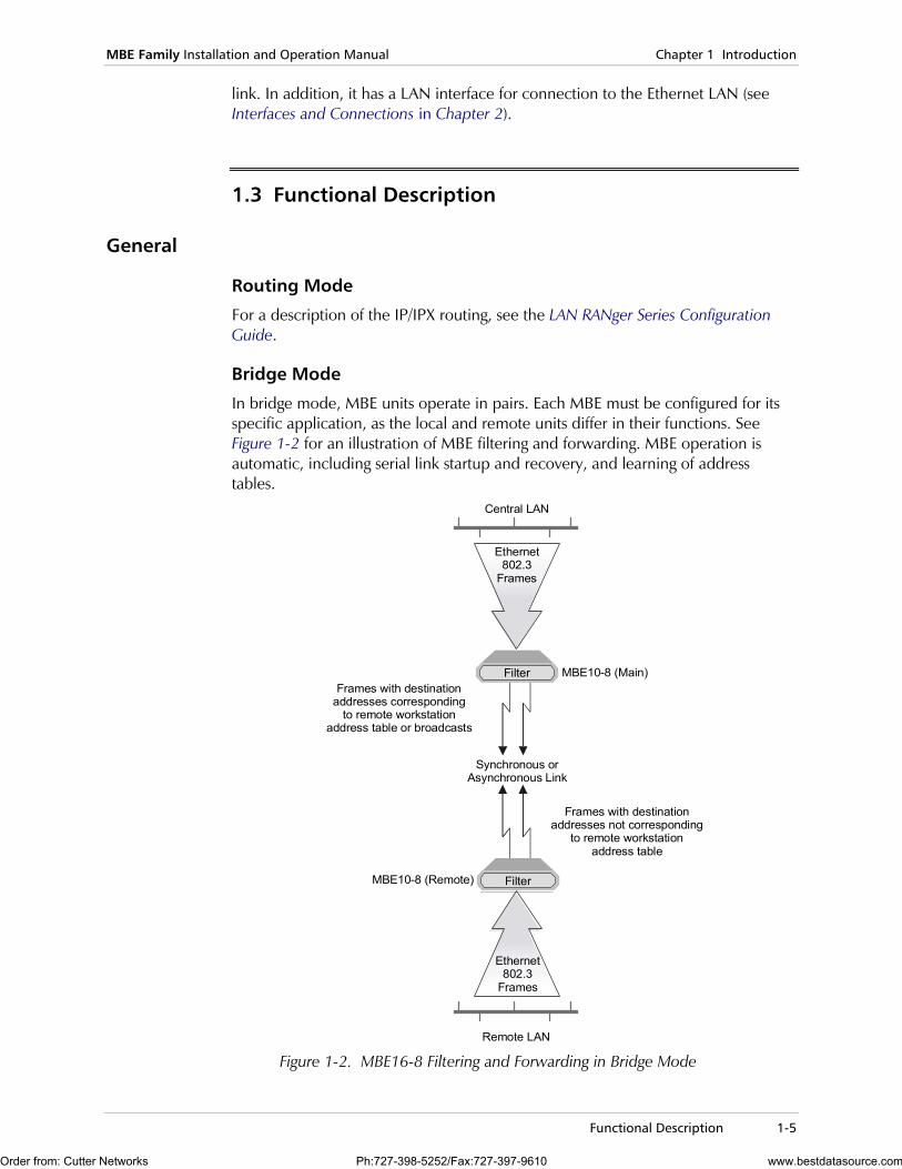
Bridge Mode
In bridge mode, MBE units operate in pairs. Each MBE must be configured for its specific application, as the local and remote units differ in their functions. See Figure 1-2 for an illustration of MBE filtering and forwarding. MBE operation is automatic, including serial link startup and recovery, and learning of address tables.
MBE10-8 (Main)
MBE10-8 (Remote)
Remote LAN
Synchronous orAsynchronous Link
Frames with destination addresses corresponding
to remote workstationaddress table or broadcasts
Frames with destination addresses not corresponding
to remote workstationaddress table
Filter
Filter
Ethernet802.3
Frames
Central LAN
Ethernet802.3
Frames
Figure 1-2. MBE16-8 Filtering and Forwarding in Bridge Mode
Order from: Cutter Networks Ph:727-398-5252/Fax:727-397-9610 www.bestdatasource.com
Chapter 1 Introduction MBE Family Installation and Operation Manual
1-6 Functional Description
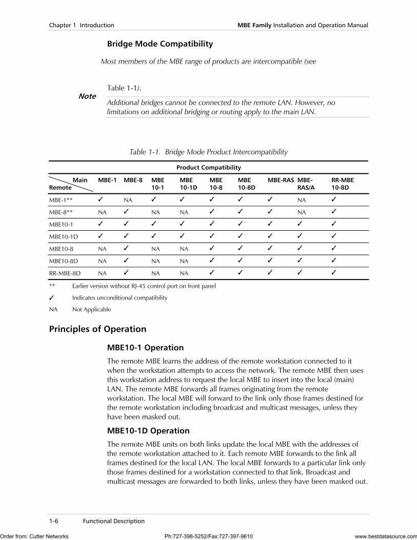
Bridge Mode Compatibility
Most members of the MBE range of products are intercompatible (see
Table 1-1).
Additional bridges cannot be connected to the remote LAN. However, no limitations on additional bridging or routing apply to the main LAN.
Table 1-1. Bridge Mode Product Intercompatibility
Product Compatibility
Main Remote
MBE-1 MBE-8 MBE 10-1
MBE 10-1D
MBE 10-8
MBE 10-8D
MBE-RAS MBE-RAS/A
RR-MBE 10-8D
MBE-1** NA NA
MBE-8** NA NA NA NA
MBE10-1
MBE10-1D
MBE10-8 NA NA NA
MBE10-8D NA NA NA
RR-MBE-8D NA NA NA
** Earlier version without RJ-45 control port on front panel
Indicates unconditional compatibility
NA Not Applicable
Principles of Operation
MBE10-1 Operation
The remote MBE learns the address of the remote workstation connected to it when the workstation attempts to access the network. The remote MBE then uses this workstation address to request the local MBE to insert into the local (main) LAN. The remote MBE forwards all frames originating from the remote workstation. The local MBE will forward to the link only those frames destined for the remote workstation including broadcast and multicast messages, unless they have been masked out.
MBE10-1D Operation
The remote MBE units on both links update the local MBE with the addresses of the remote workstation attached to it. Each remote MBE forwards to the link all frames destined for the local LAN. The local MBE forwards to a particular link only those frames destined for a workstation connected to that link. Broadcast and multicast messages are forwarded to both links, unless they have been masked out.
Note
Order from: Cutter Networks Ph:727-398-5252/Fax:727-397-9610 www.bestdatasource.com
MBE Family Installation and Operation Manual Chapter 1 Introduction
Functional Description 1-7
MBE10-8 Operation On power-up, both the local and remote MBE10-8s will connect to their respective LANs. The remote MBE10-8 continuously learns the addresses of workstations on the remote LAN and updates the local MBE10-8 with these addresses (up to 80 addresses). The remote MBE10-8 forwards all frames to the local LAN that are not addressed to workstations on the remote LAN. The local MBE10-8 forwards all frames that have destination addresses belonging to one of the remote workstations to the link. Broadcast and multicast packets are always forwarded in both directions, unless they are masked out using the filtering tool (see the LAN RANger Series Configuration Guide).
MBE10-8D Operation Operational characteristics of MBE10-8D are identical, in most respects, to those of MBE10-8, except that MBE10-8D (located at the local LAN) supports connection of two remote LANs (one per link). MBE10-8D supports up to 80 addresses per LAN providing a total of 160. Broadcast and multicast packets are always forwarded in both directions, unless masked out using the filtering tool (see the LAN RANger Series Configuration Guide). MBE10-8D can also be installed on a remote LAN where one link serves as a backup link to the other.
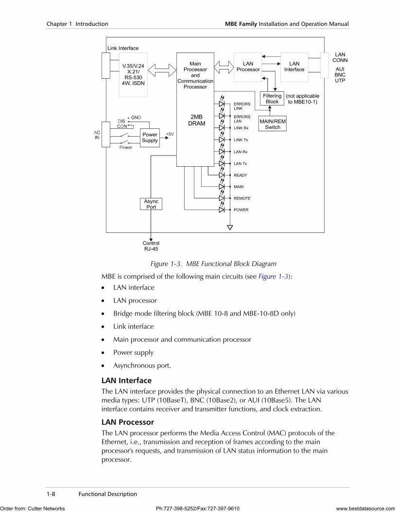
Functional Block Diagram Figure 1-3 shows the functional circuitry of the MBE unit.
Order from: Cutter Networks Ph:727-398-5252/Fax:727-397-9610 www.bestdatasource.com
Chapter 1 Introduction MBE Family Installation and Operation Manual
1-8 Functional Description
MainProcessor
andCommunication
Processor
2MBDRAM
LANProcessor
LANInterface
FilteringBlock
MAIN/REMSwitch
Link Interface
(not applicable to MBE10-1)
AsyncPort
ControlRJ-45
LANCONN
PowerSupply
AUIBNCUTP
V.35/V.24X.21/
RS-5304W, ISDN
ERRORSLINK
ERRORSLAN
LINK Rx
LINK Tx
LAN Rx
LAN Tx
READY
MAIN
REMOTE
POWER
Figure 1-3. MBE Functional Block Diagram
MBE is comprised of the following main circuits (see Figure 1-3):
• LAN interface
• LAN processor
• Bridge mode filtering block (MBE 10-8 and MBE-10-8D only)
• Link interface
• Main processor and communication processor
• Power supply
• Asynchronous port.
LAN Interface The LAN interface provides the physical connection to an Ethernet LAN via various media types: UTP (10BaseT), BNC (10Base2), or AUI (10Base5). The LAN interface contains receiver and transmitter functions, and clock extraction.
LAN Processor The LAN processor performs the Media Access Control (MAC) protocols of the Ethernet, i.e., transmission and reception of frames according to the main processor's requests, and transmission of LAN status information to the main processor.
Order from: Cutter Networks Ph:727-398-5252/Fax:727-397-9610 www.bestdatasource.com

MBE Family Installation and Operation Manual Chapter 1 Introduction
Functional Description 1-9
Bridge Mode Filtering Block (MBE10-8 and MBE10-8D only) In addition to MBE10-1 functions, MBE10-8 and MBE10-8D have a filtering block. The filtering block in the local MBE compares the destination address of every frame transmitted on the main LAN to the table of remote workstation addresses. The result of the filtering block comparison generates a copy/not copy frame command for the LAN processor.
If a frame is addressed to one of the remote workstations, the local MBE forwards this frame to the link. The remote MBE compares the destination address of every frame transmitted on the remote LAN with the remote workstation address table. All frames in the remote LAN, containing destination addresses not included in the remote workstation address table, will be forwarded to the link by the remote MBE.
If the frame destination address is of the broadcast or multicast type, the filtering block compares the source address of the frame to the remote workstation address table. This source address check results in a copy/not copy command for the LAN processor.
Link Interface The link interface provides the physical connection to either V.24/RS-232, V.35, RS-530, V.36, 4W, X.21, ISDN or DDS links. The 4W interface provides an internal short range modem with internal clock. DCE mode is provided for bench testing by V.24 and V.35 link interfaces. In DCE mode, the internal clock rate can be adjusted by selecting options from the internal clock rate setup menu (see "Internal Clock Rate Setup" in the LAN RANger Series Configuration Guide).
Main Processor and Communication Processor The main processor controls the LAN and communication processors. It performs buffer management and transfers the frames received from the LAN for transmission to the link and vice versa.
The communication processor provides an HDLC link for transmission and reception of frames to the main processor. Error checks and retransmissions ensure an error-free link.
Power Supply The MBE power supply provides required operating voltages. The power supply input ranges between 100 VAC to 240 VAC.
Asynchronous Control Port The RJ-45 control port provides setup, configuration, and monitoring and download interface using an asynchronous ASCII terminal as a terminal emulator.
Management Quick setup and configuration is performed via a terminal emulator attached to the control port, or via TELNET access to the device over the LAN or WAN.
An SNMP agent provides in-band or out-of-band management by RADview or by any other standard SNMP management station.
Software downloading is available through the control port, using XMODEM, and through the LAN or WAN using TFTP. Parameter file downloading and uploading is available through the LAN or WAN using TFTP.
Order from: Cutter Networks Ph:727-398-5252/Fax:727-397-9610 www.bestdatasource.com

Chapter 1 Introduction MBE Family Installation and Operation Manual
1-10 Technical Specifications
Product configurations and software are saved in flash memory. Two versions of the software are stored for redundancy.
1.4 Technical Specifications
LAN Interface Standard Conforms to Ethernet/IEEE 802.3
Type 10Base5 (AUI)
10Base2 (BNC) (Thin Coax)
10BaseT (UTP)
Connectors 10Base5: 15-pin D-type, female
10Base2: BNC female
10BaseT: RJ-45
LINK Interface
Interface/ Connectors
V.35*: 34-pin female
V.24/RS-232*: 25-pin D-type, female
X.21: 15-pin D-type, female (through adapter cable)
V.36/RS-422: 37-pin D-type, female (through adapter cable)
RS-530: 25-pin D-type, female
4W: 5-screw terminal block
Basic Rate ISDN ("S" or "U" interface) – RJ-45
CSU/DSU: RJ-45
Note: *The interface can function as DTE or DCE.
Protocol Synchronous: HDLC-based
Asynchronous: Programmable UART
Data Rates V.24/RS-232 (Synchronous): up to 64 kbps
V.24/RS-232 (Asynchronous): 2.4 to 115.2 kbps
V.35, X.21, V.36/RS-422, RS-530: up to 1.5 Mbps
4W: 16 to 768 kbps (selectable, internal clock)
DDS: up to 56 kbps
Basic Rate ISDN: 56, 64, 112, 128 kbps
Order from: Cutter Networks Ph:727-398-5252/Fax:727-397-9610 www.bestdatasource.com
MBE Family Installation and Operation Manual Chapter 1 Introduction
Technical Specifications 1-11
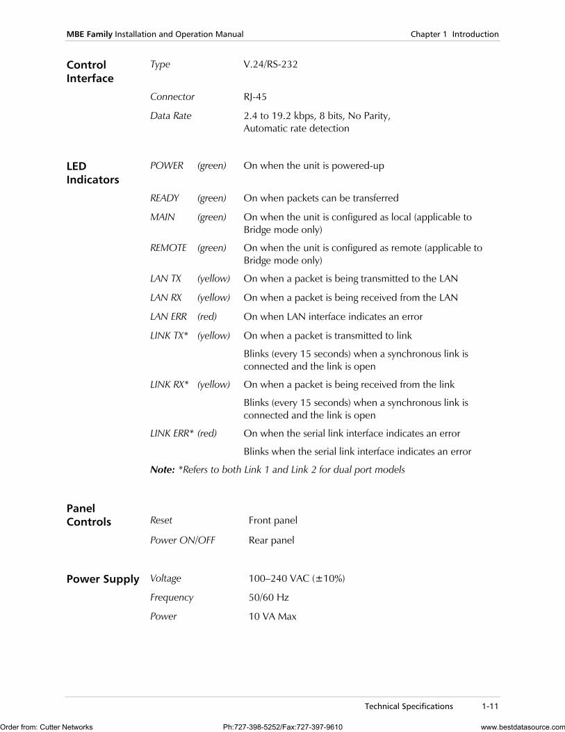
Control Interface
Type V.24/RS-232
Connector RJ-45
Data Rate 2.4 to 19.2 kbps, 8 bits, No Parity, Automatic rate detection
LED Indicators
POWER (green) On when the unit is powered-up
READY (green) On when packets can be transferred
MAIN (green) On when the unit is configured as local (applicable to Bridge mode only)
REMOTE (green) On when the unit is configured as remote (applicable to Bridge mode only)
LAN TX (yellow) On when a packet is being transmitted to the LAN
LAN RX (yellow) On when a packet is being received from the LAN
LAN ERR (red) On when LAN interface indicates an error
LINK TX* (yellow) On when a packet is transmitted to link
Blinks (every 15 seconds) when a synchronous link is connected and the link is open
LINK RX* (yellow) On when a packet is being received from the link
Blinks (every 15 seconds) when a synchronous link is connected and the link is open
LINK ERR* (red)
On when the serial link interface indicates an error
Blinks when the serial link interface indicates an error
Note: *Refers to both Link 1 and Link 2 for dual port models
Panel Controls
Reset
Front panel
Power ON/OFF Rear panel
Power Supply Voltage 100–240 VAC (±10%)
Frequency 50/60 Hz
Power 10 VA Max
Order from: Cutter Networks Ph:727-398-5252/Fax:727-397-9610 www.bestdatasource.com
Chapter 1 Introduction MBE Family Installation and Operation Manual
1-12 Technical Specifications
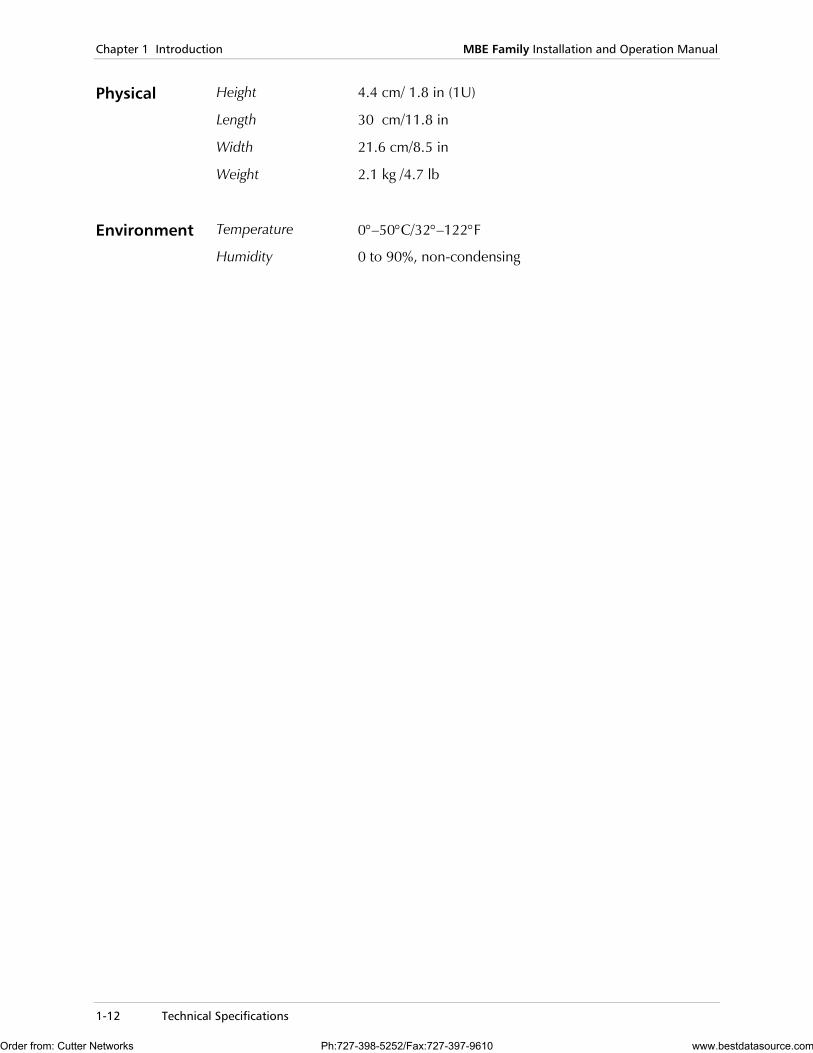
Physical Height 4.4 cm/ 1.8 in (1U)
Length 30 cm/11.8 in
Width 21.6 cm/8.5 in
Weight 2.1 kg /4.7 lb
Environment Temperature 0°–50°C/32°–122°F
Humidity 0 to 90%, non-condensing
Order from: Cutter Networks Ph:727-398-5252/Fax:727-397-9610 www.bestdatasource.com
Site Requirements and Prerequisites 2-1
Chapter 2 Installation This chapter describes the basic installation procedures for the MBE unit, including:
• Site requirements and prerequisites
• Package contents
• Equipment needed
• Installation and setup.
2.1 Introduction
MBE is delivered completely assembled. For instructions on installation of a single unit or two units in a 19-inch rack refer to the Rack Mounting Kit for 19-inch Racks guide that comes with the RM kit.
After installing the unit, see Chapter 3, Operation for operating instructions.
In case a problem is encountered, refer to Chapter 4 for fault isolation and troubleshooting instructions.
Any adjustments, maintenance or repairs should be performed only by a skilled technician who is aware of the hazards involved. Always observe standard safety precautions during installation, operation, and maintenance of this product.
2.2 Site Requirements and Prerequisites
Inspect the equipment container before unpacking. Note and report evidence of damage immediately to your RAD distributor. Install the MBE unit within 1.5m (5 ft) of a grounded AC outlet furnishing 240V (115V).
Allow at least 90 cm (36") of frontal clearance for operator access. Allow at least 10 cm (4") clearance at the rear of the unit for interface cable connections.
The ambient temperature should be regulated between 0° to 50°C (32°F to 122°F) at a relative humidity of up to 90%, non-condensing.
Note
Order from: Cutter Networks Ph:727-398-5252/Fax:727-397-9610 www.bestdatasource.com

Chapter 2 Installation MBE Family Installation and Operation Manual
2-2 Installation and Setup
2.3 Package Contents
The following items are included in the MBE product packaging:
• One MBE standalone unit
• Control cable with RJ-45 connector – CBL-RJ45/D9/F/6FT
• AC power cord
• MBE Family Installation and Operation Manual
• LAN RANger Series Configuration Guide.
2.4 Equipment Needed
The following equipment is required to install the MBE:
• ASCII terminal or PC terminal emulator
• CBL-RJ45/D9/F/6FT control cable with RJ-45 connector (supplied with the device) for connection to the configuration terminal.
2.5 Installation and Setup
MBE is a standalone unit intended for tabletop or bench installation. It is delivered completely assembled. No provision is made for bolting the unit on the tabletop.
To install the MBE unit:
1. Determine the required configuration of MBE and set the internal jumpers accordingly.
2. Connect the line (see Connecting the Interfaces below).
3. Connect the LAN (see Connecting the LAN below).
4. Connect power to the unit (see Connecting the Power below).
Access to the inside of the equipment is permitted only to authorized and qualified personnel. To avoid accidental electric shock, always disconnect the interface cables and power cord before removing the unit from its casing. Any adjustment, maintenance or repair of the opened instrument under voltage must be avoided as much as possible, and when inevitable, should be carried out only by a skilled technician who is aware of the hazards involved.
Warning
Order from: Cutter Networks Ph:727-398-5252/Fax:727-397-9610 www.bestdatasource.com
MBE Family Installation and Operation Manual Chapter 2 Installation
Installation and Setup 2-3
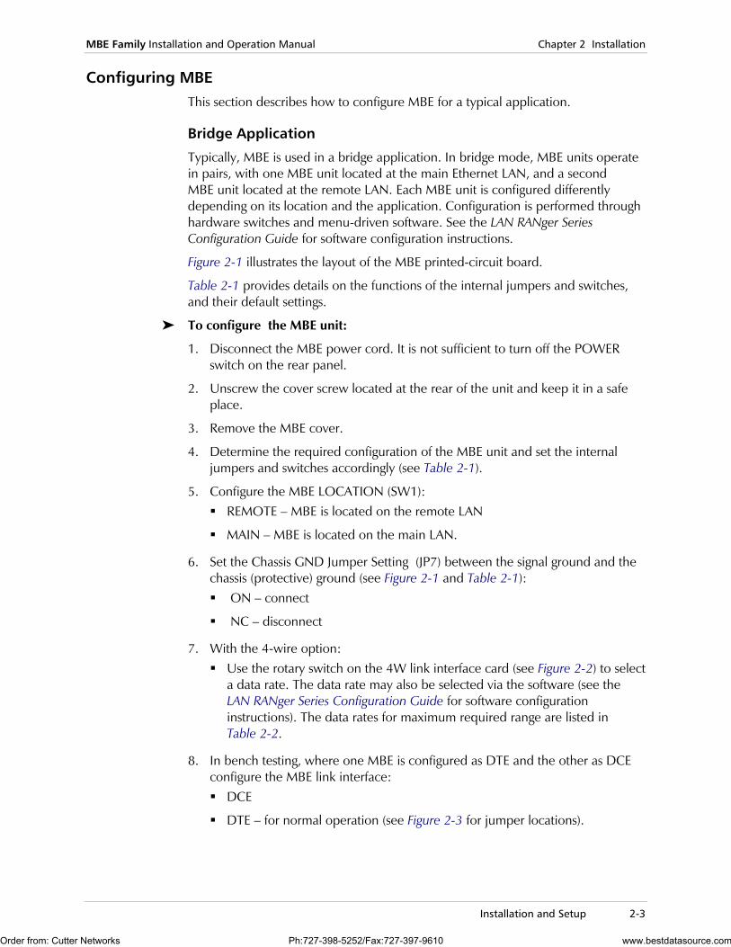
Configuring MBE This section describes how to configure MBE for a typical application.
Bridge Application
Typically, MBE is used in a bridge application. In bridge mode, MBE units operate in pairs, with one MBE unit located at the main Ethernet LAN, and a second MBE unit located at the remote LAN. Each MBE unit is configured differently depending on its location and the application. Configuration is performed through hardware switches and menu-driven software. See the LAN RANger Series Configuration Guide for software configuration instructions.
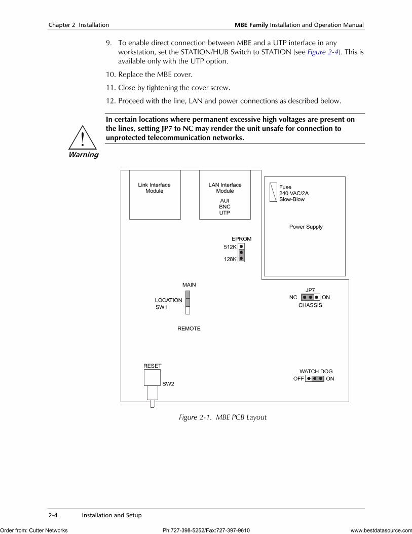
Figure 2-1 illustrates the layout of the MBE printed-circuit board.
Table 2-1 provides details on the functions of the internal jumpers and switches, and their default settings.
To configure the MBE unit:
1. Disconnect the MBE power cord. It is not sufficient to turn off the POWER switch on the rear panel.
2. Unscrew the cover screw located at the rear of the unit and keep it in a safe place.
3. Remove the MBE cover.
4. Determine the required configuration of the MBE unit and set the internal jumpers and switches accordingly (see Table 2-1).
5. Configure the MBE LOCATION (SW1): REMOTE – MBE is located on the remote LAN
MAIN – MBE is located on the main LAN.
6. Set the Chassis GND Jumper Setting (JP7) between the signal ground and the chassis (protective) ground (see Figure 2-1 and Table 2-1): ON – connect
NC – disconnect
7. With the 4-wire option: Use the rotary switch on the 4W link interface card (see Figure 2-2) to select
a data rate. The data rate may also be selected via the software (see the LAN RANger Series Configuration Guide for software configuration instructions). The data rates for maximum required range are listed in Table 2-2.
8. In bench testing, where one MBE is configured as DTE and the other as DCE configure the MBE link interface: DCE
DTE – for normal operation (see Figure 2-3 for jumper locations).
Order from: Cutter Networks Ph:727-398-5252/Fax:727-397-9610 www.bestdatasource.com
Chapter 2 Installation MBE Family Installation and Operation Manual
2-4 Installation and Setup
9. To enable direct connection between MBE and a UTP interface in any workstation, set the STATION/HUB Switch to STATION (see Figure 2-4). This is available only with the UTP option.
10. Replace the MBE cover.
11. Close by tightening the cover screw.
12. Proceed with the line, LAN and power connections as described below.
In certain locations where permanent excessive high voltages are present on the lines, setting JP7 to NC may render the unit unsafe for connection to unprotected telecommunication networks.
Power Supply
EPROM
MAIN
REMOTE
RESET
LOCATIONSW1
SW2
512K
128K
JP7
WATCH DOG
NC
OFF
ON
ON
CHASSIS
Link InterfaceModule
LAN InterfaceModule
AUIBNCUTP
Fuse240 VAC/2ASlow-Blow
Figure 2-1. MBE PCB Layout
Warning
Order from: Cutter Networks Ph:727-398-5252/Fax:727-397-9610 www.bestdatasource.com

MBE Family Installation and Operation Manual Chapter 2 Installation
Installation and Setup 2-5
Table 2-1. MBE Switches and Jumpers
Switch/Jumper Name
Reference Possible Settings
Factory Setting
Description
LOCATION SW1
Figure 2-1 REMOTE
MAIN
MAIN
MBE is located on the remote LAN.
MBE is located on the main (local) LAN.
CHASSIS (Ground Connection) JP7
Figure 2-1 NC (Not Connected)
ON (Connected)
NC Disconnect signal ground from chassis (protective) ground.
Connect signal ground to chassis (protective) ground.
RESET (Front panel button)
Figure 2-1 System Reset
EPROM SIZE Figure 2-1 512 KB
128 KB
128 KB
For manufacturer's use only.
WATCH DOG Figure 2-1 OFF
ON
ON
For manufacturer's use only.
CLOCK SPEED (4W Interface only)
Figure 2-2 7 – 16 kbps 6 – 32 kbps 5 – 48 kbps 4 – 64 kbps 3 – 96 kbps 2 – 128 kbps 1 – 256 kbps 0 – 768 kbps
768 kbps
Select data rate on 4-wire internal modem.
Select the highest possible data rate for respective range and wire gauge.
DTE/DCE Jumper (V24, V35 Interface only)
Figure 2-3 DTE
DCE
DTE Select DTE mode for normal operation.
Select DCE mode for bench testing.
STATION HUB Switch (UTP Interface only)
Figure 2-4 STATION
HUB
HUB
Interchanges the Rx pair with the Tx pair.
Order from: Cutter Networks Ph:727-398-5252/Fax:727-397-9610 www.bestdatasource.com

Chapter 2 Installation MBE Family Installation and Operation Manual
2-6 Installation and Setup
0
34
57 6
12
BOT
Rate7682561289664483216
POS01234567
0 0
3 34 4
5 57 76 6
1 12 2
BOT TOP
Rate7682561289664483216
POS01234567
IL-4W IL-4WD
Figure 2-2. 4W Date Rate Selection
BOT- corresponds to the lower link connector. TOP - corresponds to the upper link connector.
Table 2-2. MBE Four-Wire Data Rate
Data Rate (kbps)
Range km/miles
Selector Position
768 1.0/0.6 0
256 3.0/1.8 1
128 4.5/2.7 2
96 5.5/3.3 3
64 6/3.7 4
48 7/4.3 5
32 6.5/4.0 6
16 6/3.7 7
Note
Order from: Cutter Networks Ph:727-398-5252/Fax:727-397-9610 www.bestdatasource.com

MBE Family Installation and Operation Manual Chapter 2 Installation
Installation and Setup 2-7
Link-2 TOPDTE
DTE/DCEJumper
DCE
Link-1 BOTTOM
DTE/DCEJumper
V.35 Interface
DTE
DCE
V.24D, V.35D, V.24 V.35
Figure 2-3. Link Interface Card
LINK-2 corresponds to the upper interface connector. LINK-1 corresponds to the lower interface connector.
STN HUB6
Figure 2-4. LAN Interface Module (UTP)
Connecting the Interfaces Figure 2-5 illustrates the MBE unit’s rear panel with a V.35 connector.
Figure 2-6 illustrates the MBE unit’s rear panel with a V.24 connector.
Note
Order from: Cutter Networks Ph:727-398-5252/Fax:727-397-9610 www.bestdatasource.com

Chapter 2 Installation MBE Family Installation and Operation Manual
2-8 Installation and Setup
POWEROI AUI
TO V.35 LINE
100-230 VAC
Figure 2-5. MBE Rear Panel, V.35 Connector
POWER
POWER
O
O
I
I
TO RS-232/V.24
LINK 2 RS-232/V.24
LINK 1 RS-232/V.24
AUI
AUI
100-230 VAC
100-230 VAC
Figure 2-6. MBE Rear Panel, V.24 Connector
Connecting the Line A connector is provided to connect each interface to the communication link.
To connect the line:
• See Appendix A for LINK connector pin assignments. Note that the X.21 and V.36 connections are provided by adapter cables to the RS-530 (25-pin connector) on the MBE rear panel.
Interface cards are interchangeable. Consult your RAD dealer for details.
Connecting the LAN To connect to the LAN:
• Use a standard AUI (15-pin, D-type), 10Base2 (BNC) or 10BaseT (RJ-45) connector, provided by RAD.
To ensure compliance with electromagnetic compatibility (EMC) requirements, it is recommended that you only use shielded data cables with this product. Make sure that the shield is connected to the metallic hood of the cable connector.
For units with V.35 ports, in order to protect against electrostatic discharge (ESD) into the port, use a connector with an overlapping hood that completely covers the pin connection.
Caution
Order from: Cutter Networks Ph:727-398-5252/Fax:727-397-9610 www.bestdatasource.com

MBE Family Installation and Operation Manual Chapter 2 Installation
Installation and Setup 2-9
Connecting the Power
AC Power
Supply AC power to the MBE unit through the 1.5m (5 ft) standard power cable terminated by a standard 3-prong plug. The cable is provided with the unit.
A 2A slow-blow fuse is located in the power supply unit.
To prevent electrical fire hazard, always replace the fuse with the same type and rating as indicated.
➤ To connect AC power to the MBE unit:
1. Connect the power cable to the power connector on the MBE rear panel.
2. Connect the power cable to the mains outlet.
3. Set the POWER switch to ON.
Warning
Order from: Cutter Networks Ph:727-398-5252/Fax:727-397-9610 www.bestdatasource.com

Chapter 2 Installation MBE Family Installation and Operation Manual
2-10 Installation and Setup
Order from: Cutter Networks Ph:727-398-5252/Fax:727-397-9610 www.bestdatasource.com

Front Panel Controls and Indicators 3-1
Chapter 3 Operation This chapter:
• Describes MBE front panel controls and indicators
• Provides basic operation instructions.
For in-depth information on configuration of MBE, see the LAN RANger Series Configuration Guide.
3.1 Front Panel Controls and Indicators
Table 3-1 lists the functions of the MBE controls and indicators located on the front panel.
RESET
RESET
CONTROL
CONTROL
MBE-8
MBE-8D
LAN
LAN
RAN
RAN
ger
ger
POWER
POWER
READY
READY
MAIN
LAN
LAN
TX
TX
RX
RX
ERR
ERR
REMOTE
REMOTE
LINK
LINK 1LINK 2
MAIN
Figure 3-1. MBE Front Panel
Table 3-1. Front Panel Controls and Indicators
Controls and Indicators Color Function
RESET Used to reset MBE. See the LAN RANger Series Configuration Guide for software initiated reset
RJ45 SOCKET (CONTROL)
Used for connection of terminal for diagnostics, configuration, monitoring and downloading
POWER Green On when MBE is powered on
READY Green On continuously during normal operation
Order from: Cutter Networks Ph:727-398-5252/Fax:727-397-9610 www.bestdatasource.com

Chapter 3 Operation MBE Family Installation and Operation Manual
3-2 Operating Instructions
Table 3-1. Front Panel Controls and Indicators (Cont.)
Controls and Indicators Color Function
MAIN Green On when MBE is configured for local operation (applicable to bridge mode only)
REMOTE Green On when MBE is configured for remote operation (applicable to bridge mode only)
LAN TX Yellow On when packets are being transmitted to the LAN
RX Yellow On when packets are being received by the LAN
ERR Red On continuously when connection to LAN has failed
LINK TX Yellow On when a packet is being transmitted to the link
RX Yellow On when a packet is being received from the link
ERR Red On when discontinuity occurs in the link or if other Communication link faults exist
3.2 Operating Instructions
GROUNDING - This unit should always be grounded through the protective earth lead of the power cable. Before connecting AC power to this unit, the mains plug should be inserted only into a socket outlet provided with a protective earth contact. The protective action must not be negated by use of an extension cord (power cable) without a protective conductor (grounding). Interruption of the protective (grounding) conductor (inside or outside the unit), or disconnection of the protective earth terminal can render this unit dangerous.
Initial Setup To begin configuring MBE:
1. Connect MBE to an ASCII terminal or a PC terminal emulator.
2. Connect the CBL-RJ45/D9/F/6FT control cable, supplied with MBE, between the RJ-45 control port on the MBE front panel, and the DB-9 connector on the terminal.
3. Set the terminal to work at any baud rate from 4.8 to 19.2 kbps, No Parity, 8 data bits, and 1 stop bit.
It is suggested to use 9.6 kbps.
For complete configuration details, see the LAN RANger Series Configuration Guide.
Warning
Note
Order from: Cutter Networks Ph:727-398-5252/Fax:727-397-9610 www.bestdatasource.com

MBE Family Installation and Operation Manual Chapter 3 Operation
Operating Instructions 3-3
Power-on To power-up MBE:
1. Set the POWER switch on the rear panel to the ON position. The POWER indicator lights up, indicating that MBE is powered on. After about 1 minute, the operational status screen appears on the terminal screen.
2. Press the <Enter> key several times to display the password prompt.
Operating MBE To operate MBE:
1. Configure MBE according to the application (see the LAN RANger Series Configuration Guide).
2. During normal operation (when the remote workstations are active): The READY indicator lights up continuously
The Tx and Rx indicators blink occasionally
The LAN and LINK error indicators remain OFF.
Power-off To power-off MBE:
• Set the POWER switch on the rear panel to the OFF position.
Order from: Cutter Networks Ph:727-398-5252/Fax:727-397-9610 www.bestdatasource.com

Chapter 3 Operation MBE Family Installation and Operation Manual
3-4 Operating Instructions
Order from: Cutter Networks Ph:727-398-5252/Fax:727-397-9610 www.bestdatasource.com

Alarms and Troubleshooting 4-1
Chapter 4 Troubleshooting and Diagnostics This chapter provides:
• A procedure for performing a ping connectivity test
• Troubleshooting solutions for possible operational and communication problems.
4.1 Diagnostic Test
Ping Terminal To check the status of the MBE unit's connectivity, you initiate a ping test to all connected IP addresses.
To perform the ping test:
1. In the Main menu, type 5 (Diagnostic Tools).
2. Type 1 (Ping Terminal).
3. Type your terminal's IP address and press <Enter>. The results of the Ping test appear on the screen and run continuously until you stop the test.
4. To stop the ping test, press <Enter>.
4.2 Alarms and Troubleshooting
Observe safety precautions while working on the unit, especially if the cover is removed.
Some common faults and their solutions are listed in the Table 4-1. Some faults may occur due to incorrect configuration settings with regard to MBE application and location. Link errors are sometimes caused by loose contact between connectors or lack of cable continuity.
Warning
Order from: Cutter Networks Ph:727-398-5252/Fax:727-397-9610 www.bestdatasource.com
Chapter 4 Troubleshooting and Diagnostics MBE Family Installation and Operation Manual
4-2 Alarms and Troubleshooting
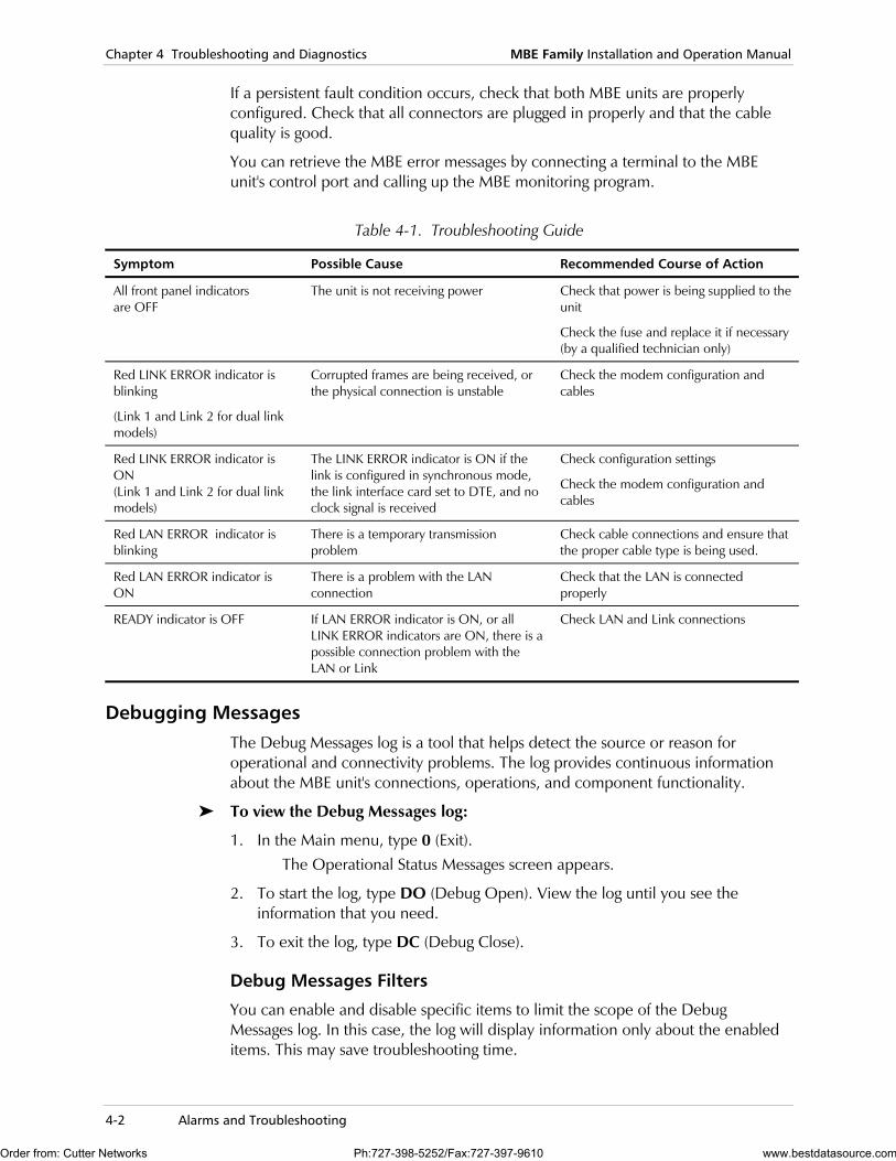
If a persistent fault condition occurs, check that both MBE units are properly configured. Check that all connectors are plugged in properly and that the cable quality is good.
You can retrieve the MBE error messages by connecting a terminal to the MBE unit's control port and calling up the MBE monitoring program.
Table 4-1. Troubleshooting Guide
Symptom Possible Cause Recommended Course of Action
All front panel indicators are OFF
The unit is not receiving power Check that power is being supplied to the unit
Check the fuse and replace it if necessary (by a qualified technician only)
Red LINK ERROR indicator is blinking
(Link 1 and Link 2 for dual link models)
Corrupted frames are being received, or the physical connection is unstable
Check the modem configuration and cables
Red LINK ERROR indicator is ON (Link 1 and Link 2 for dual link models)
The LINK ERROR indicator is ON if the link is configured in synchronous mode, the link interface card set to DTE, and no clock signal is received
Check configuration settings
Check the modem configuration and cables
Red LAN ERROR indicator is blinking
There is a temporary transmission problem
Check cable connections and ensure that the proper cable type is being used.
Red LAN ERROR indicator is ON
There is a problem with the LAN connection
Check that the LAN is connected properly
READY indicator is OFF If LAN ERROR indicator is ON, or all LINK ERROR indicators are ON, there is a possible connection problem with the LAN or Link
Check LAN and Link connections
Debugging Messages The Debug Messages log is a tool that helps detect the source or reason for operational and connectivity problems. The log provides continuous information about the MBE unit's connections, operations, and component functionality.
To view the Debug Messages log:
1. In the Main menu, type 0 (Exit). The Operational Status Messages screen appears.
2. To start the log, type DO (Debug Open). View the log until you see the information that you need.
3. To exit the log, type DC (Debug Close).
Debug Messages Filters
You can enable and disable specific items to limit the scope of the Debug Messages log. In this case, the log will display information only about the enabled items. This may save troubleshooting time.
Order from: Cutter Networks Ph:727-398-5252/Fax:727-397-9610 www.bestdatasource.com
MBE Family Installation and Operation Manual Chapter 4 Troubleshooting and Diagnostics
Alarms and Troubleshooting 4-3
To filter the Debug Messages log:
1. In the Main menu, type 0 (Exit). The Operational Status Messages screen appears.
2. Type DO (Debug Open). The Debug Messages screen appears.
3. Type DH (Debug Help). A list of operational/connectivity categories appears. Each category has the values: Enable or Disable. An enabled item appears in the log, and a disabled item is not included.
4. To enable or disable items, type the number of the item and choose the appropriate value.
Resetting MBE to Factory Settings
You can reset MBE to the default factory settings. This is useful if you want to reconfigure MBE and remove previous configuration data.
To reset the MBE to the factory settings:
1. In the Main menu, type 0 (Exit). The Operational Status Messages screen appears.
2. Type DO (Debug Open) to perform the reset. The Debug Messages screen appears.
3. Type SF (Set Factory) to perform the reset.
Order from: Cutter Networks Ph:727-398-5252/Fax:727-397-9610 www.bestdatasource.com

Chapter 4 Troubleshooting and Diagnostics MBE Family Installation and Operation Manual
4-4 Alarms and Troubleshooting
Order from: Cutter Networks Ph:727-398-5252/Fax:727-397-9610 www.bestdatasource.com
A-1
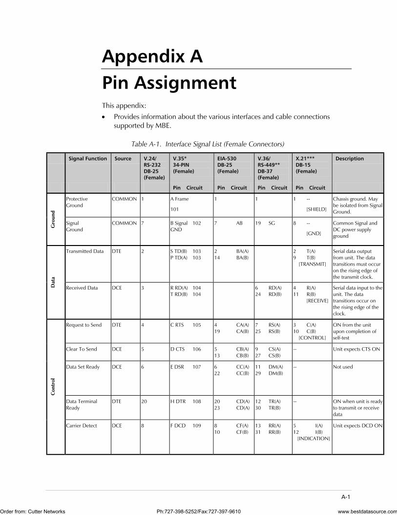
Appendix A Pin Assignment This appendix:
• Provides information about the various interfaces and cable connections supported by MBE.
Table A-1. Interface Signal List (Female Connectors)
Signal Function Source V.24/ RS-232 DB-25 (Female)
V.35* 34-PIN (Female)
EIA-530 DB-25 (Female)
V.36/ RS-449** DB-37 (Female)
X.21*** DB-15 (Female)
Description
Pin Circuit Pin Circuit Pin Circuit Pin Circuit
Protective Ground
COMMON 1 A Frame
101
1 1 1 --
[SHIELD]
Chassis ground. May be isolated from Signal Ground.
Gro
und
Signal Ground
COMMON 7 B Signal 102 GND
7 AB 19 SG 8 --
[GND]
Common Signal and DC power supply ground
Transmitted Data DTE 2 S TD(B) 103 P TD(A) 103
2 BA(A) 14 BA(B)
2 T(A) 9 T(B) [TRANSMIT]
Serial data output from unit. The data transitions must occur on the rising edge of the transmit clock.
Dat
a
Received Data DCE 3 R RD(A) 104 T RD(B) 104
6 RD(A) 24 RD(B)
4 R(A) 11 R(B) [RECEIVE]
Serial data input to the unit. The data transitions occur on the rising edge of the clock.
Request to Send DTE 4 C RTS 105 4 CA(A) 19 CA(B)
7 RS(A) 25 RS(B)
3 C(A) 10 C(B) [CONTROL]
ON from the unit upon completion of self-test
Clear To Send DCE 5 D CTS 106 5 CB(A) 13 CB(B)
9 CS(A) 27 CS(B)
-- Unit expects CTS ON
Data Set Ready DCE 6 E DSR 107 6 CC(A) 22 CC(B)
11 DM(A) 29 DM(B)
-- Not used
Data Terminal Ready
DTE 20 H DTR 108 20 CD(A) 23 CD(A)
12 TR(A) 30 TR(B)
-- ON when unit is readyto transmit or receive data
Con
trol
Carrier Detect DCE 8 F DCD 109 8 CF(A) 10 CF(B)
13 RR(A) 31 RR(B)
5 I(A) 12 I(B) [INDICATION]
Unit expects DCD ON
Order from: Cutter Networks Ph:727-398-5252/Fax:727-397-9610 www.bestdatasource.com
Appendix A Pin Assignment MBE Family Installation and Operation Manual
A-2
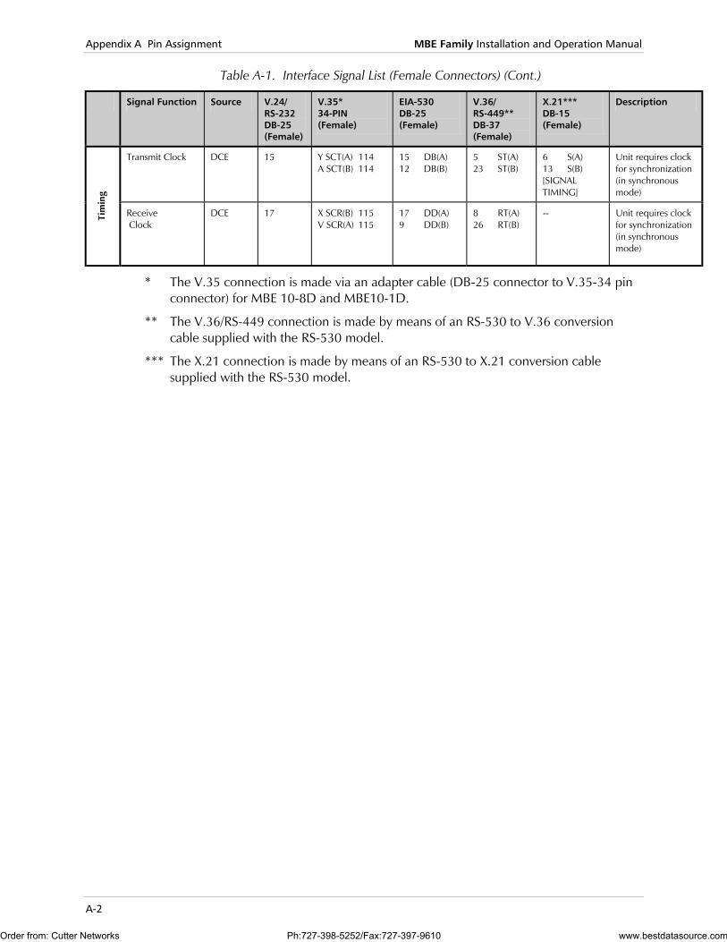
Table A-1. Interface Signal List (Female Connectors) (Cont.)
Signal Function Source V.24/ RS-232 DB-25 (Female)
V.35* 34-PIN (Female)
EIA-530 DB-25 (Female)
V.36/ RS-449** DB-37 (Female)
X.21*** DB-15 (Female)
Description
Transmit Clock DCE 15 Y SCT(A) 114 A SCT(B) 114
15 DB(A) 12 DB(B)
5 ST(A) 23 ST(B)
6 S(A) 13 S(B) [SIGNAL TIMING]
Unit requires clock for synchronization (in synchronous mode)
Tim
ing
Receive Clock
DCE 17 X SCR(B) 115 V SCR(A) 115
17 DD(A) 9 DD(B)
8 RT(A) 26 RT(B)
-- Unit requires clock for synchronization (in synchronous mode)
* The V.35 connection is made via an adapter cable (DB-25 connector to V.35-34 pin connector) for MBE 10-8D and MBE10-1D.
** The V.36/RS-449 connection is made by means of an RS-530 to V.36 conversion cable supplied with the RS-530 model.
*** The X.21 connection is made by means of an RS-530 to X.21 conversion cable supplied with the RS-530 model.
Order from: Cutter Networks Ph:727-398-5252/Fax:727-397-9610 www.bestdatasource.com

MBE Family Installation and Operation Manual Appendix A Pin Assignment
A-3
Shield 1
Signal GND 7
RTS-a 4
RTS-b 19
CTS-a 5
CTS-b 13
DCD-a 8
DCD-b 10
TC-a 15
TC-b 12
RC-a 17
RC-b 9
TD-a 2
TD-b 14
RD-a 3
RD-b 16
1 Shield
8 Signal GND
3 C-a
10 C-b
5 I-a
12 I-b
6 S-a
13 S-b
2 T-a
9 T-b
4 R-a
11 R-b
RS-530 X.21 / 15-pin
Figure A-1. Cable – CBL-530T/21C
Cable supplied with MBE for X.21 interface
Order from: Cutter Networks Ph:727-398-5252/Fax:727-397-9610 www.bestdatasource.com

Appendix A Pin Assignment MBE Family Installation and Operation Manual
A-4
1214316179241115124567820
APSRTVXUWYAA (a)CDEBFH
Shield
V.35/ DB-25 V.35/ 34-pin
RTSCTSDCE ReadyGndDCDDTE Ready
Tx
Rx
R Clk
E Clk
T Clk
Tx
Rx
Figure A-2. Cable – CBL-530/V.35/F
Cable supplied with MBE10-1D, 8D for V.35 interface
Order from: Cutter Networks Ph:727-398-5252/Fax:727-397-9610 www.bestdatasource.com
MBE Family Installation and Operation Manual Appendix A Pin Assignment
A-5
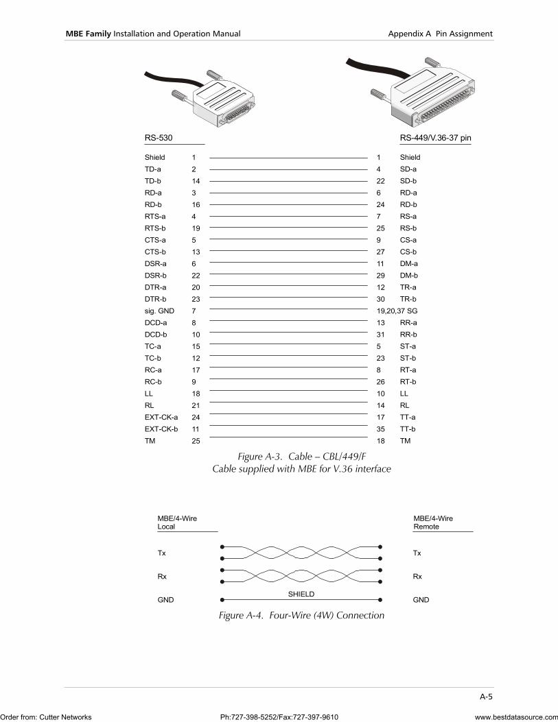
12143164195136222023781015121791821241125
14226247259271129123019,20,37 SG13315238261014173518
ShieldTD-aTD-bRD-aRD-bRTS-aRTS-bCTS-aCTS-bDSR-aDSR-bDTR-aDTR-bsig. GNDDCD-aDCD-bTC-aTC-bRC-aRC-bLLRLEXT-CK-aEXT-CK-bTM
ShieldSD-aSD-bRD-aRD-bRS-aRS-bCS-aCS-bDM-aDM-bTR-aTR-b
RR-aRR-bST-aST-bRT-aRT-bLLRLTT-aTT-bTM
RS-530 RS-449/V.36-37 pin
Figure A-3. Cable – CBL/449/F
Cable supplied with MBE for V.36 interface
MBE/4-WireLocal
MBE/4-WireRemote
Tx
Rx
GNDSHIELD
Tx
Rx
GND Figure A-4. Four-Wire (4W) Connection
Order from: Cutter Networks Ph:727-398-5252/Fax:727-397-9610 www.bestdatasource.com
Appendix A Pin Assignment MBE Family Installation and Operation Manual
A-6
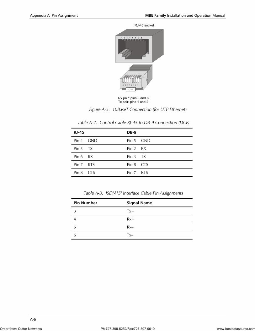
RJ-45 socket
Rx pair: pins 3 and 6Tx pair: pins 1 and 2
1 2 3 4 5 6 7 8
Figure A-5. 10BaseT Connection (for UTP Ethernet)
Table A-2. Control Cable RJ-45 to DB-9 Connection (DCE)
RJ-45 DB-9
Pin 4 GND Pin 5 GND
Pin 5 TX Pin 2 RX
Pin 6 RX Pin 3 TX
Pin 7 RTS Pin 8 CTS
Pin 8 CTS Pin 7 RTS
Table A-3. ISDN "S" Interface Cable Pin Assignments
Pin Number Signal Name
3 Tx+
4 Rx+
5 Rx–
6 Tx–
Order from: Cutter Networks Ph:727-398-5252/Fax:727-397-9610 www.bestdatasource.com

I-1
Index
—B— bridge mode, 1-5 bridges, 1-2
—C— clock, 2-5 COD, 1-3 configuration, 2-3
initial setup, 3-2 control interface, 1-11 control port, 1-9 CSLIP, 1-1
—D— datagrams, 1-2 debug, 4-2
DC, 4-2 DO, 4-2 log, 4-2
—E— errors, 4-2
—F— filtering block, 1-9 firewall, 1-3 flash, 1-3, 1-4, 1-10 frame relay, 1-1 front panel, 3-1
normal operation, 3-3
—I— installation, 2-2 interfaces, 1-9
connection, 2-7 IP routing, 1-1 IP/IPX support, 1-2 ISDN, 1-3
—J— jumpers, 2-5
—L— LAN, 1-8
connection, 2-8 interface, 1-10 processor, 1-8
LEDs, 1-11 line connection, 2-8 link interface, 1-9, 1-10
—M— MAC protocols, 1-8 management, 1-2 MBE
compatibility, 1-6 front panel, 1-4 management, 1-9 operation, 1-6 rear panel, 1-4 site requirements, 2-1
MTU, 1-2
—P— panel controls, 1-11 PAP/CHAP, 1-3 pin assignment, A-1 ping, 4-1 power, 1-11, 2-9, 3-3 power supply, 1-9, 1-11 PPP, 1-1
—Q— Quick Setup, 1-3
—R— RADview, 1-2 reset, 1-11 reset factory settings, 4-3 routers, 1-1, 1-2 routing mode, 1-5
—S— security, 1-3 Single IP, 1-3 SLIP, 1-1 SNMP management, 1-2
Order from: Cutter Networks Ph:727-398-5252/Fax:727-397-9610 www.bestdatasource.com

Index MBE Family Installation and Operation Manual
I-2
switches, 2-5
—T— technical specifications, 1-10 TELNET, 1-2
troubleshooting, 4-2
—X— XMODEM, 1-9
Order from: Cutter Networks Ph:727-398-5252/Fax:727-397-9610 www.bestdatasource.com

24 Raoul Wallenberg St., Tel Aviv 69719, IsraelTel: +972-3-6458181, Fax: +972-3-6483331, +972-3-6498250E-mail: , Web site:
Customer Response Form RAD Data Communications would like your help in improving its product documentation. Please complete and return this form by mail or by fax or send us an e-mail with your comments. Thank you for your assistance!
Manual Name: _ ____________________________________
Publication Numb
Please grade the
Installation instruc
Operating instruc
Manual organizati
Illustrations
The manual as a w
What did you like______________ ______________ ______________ ______________ ______________
[email protected] www.rad.com
M
Order from: Cutter Networks
_________________________BE Family (LAN RANger Series)
er: _ _______________________________________________
man
tions
tions
on
hole
abo____
____
____
____
____
5 3
__________72-200-02/0ual according to the following factors:
Excellent Good Fair Poor Very Poor
❒ ❒ ❒ ❒ ❒ ❒ ❒ ❒ ❒ ❒ ❒ ❒ ❒ ❒ ❒ ❒ ❒ ❒ ❒ ❒
❒ ❒ ❒ ❒ ❒
ut the manual? _________________________________________________________
_________________________________________________________
_________________________________________________________
_________________________________________________________
_________________________________________________________
Ph:727-398-5252/Fax:727-397-9610 www.bestdatasource.com

Order from: Cutter Networks Ph:727-398-5252/Fax:727-397-9610 www.bestdatasource.com

Error Report Type of Error(s) ❒ Incompatibility with product
or Problem(s): ❒ Difficulty in understanding text
❒ Regulatory information (Safety, Compliance, Warnings, etc.)
❒ Difficulty in finding needed information
❒ Missing information
❒ Illogical flow of information
❒ Style (spelling, grammar, references, etc.)
❒ Appearance
❒ Other _________
Please list the exact page numbers with the error(s), detail the errors you found (information missing, unclear or inadequately explained, etc.) and attach the page to your fax, if necessary. _________________________________________________________________________________________
_________________________________________________________________________________________
_________________________________________________________________________________________
_________________________________________________________________________________________
Please add any comments or suggestions you may have. _________________________________________________________________________________________
_________________________________________________________________________________________
_________________________________________________________________________________________
You are: ❒ Distributor
❒ End user
❒ VAR
❒ Other ________________________
Who is your distributor? _______________________________
Your name and company: ___________________________________________________________
Job title: __________________________________________________________________________
Address: __________________________________________________________________________
Direct telephone number and extension: _______________________________________________
Fax number: ______________________________________________________________________
E-mail: _____________________________________________________________________
Order from: Cutter Networks Ph:727-398-5252/Fax:727-397-9610 www.bestdatasource.com

Order from: Cutter Networks Ph:727-398-5252/Fax:727-397-9610 www.bestdatasource.com

Order from: Cutter Networks Ph:727-398-5252/Fax:727-397-9610 www.bestdatasource.com

900 Corporate Drive, Mahwah, N.J. 07430, Tel: (201) 529-1100
24 Raoul Wallenberg Street, Tel Aviv 69719, Israel, Tel: 972-3-6458181
U.S. HEADQUARTERS:
INTERNATIONAL HEADQUARTERS:
Publication No. 572-200-02/03
www.rad.com
Fax: 972-3-6498250, 972-3-6474436, Email: [email protected]
Toll Free: 1-800-444-7234, Fax: (201) 529-5777, Email: [email protected]
Order from: Cutter Networks Ph:727-398-5252/Fax:727-397-9610 www.bestdatasource.com