mbe growth control program - weizmann.ac.il
TRANSCRIPT

MBE Growth Control Program
Enrico Segre, [email protected]
version 1.0.2, commit 408547, May 5, 2020

2

Contents
I User manual 5
1 Scope and purpose of the program 7
2 Installation 92.1 Executable Build Installer and Runtime Engine . . . . . . . . . . . . . . . . . . . . . . . . . . . . . . . . . . 92.2 Updating previous distributions . . . . . . . . . . . . . . . . . . . . . . . . . . . . . . . . . . . . . . . . . . . 92.3 Note about Windows �le permissions . . . . . . . . . . . . . . . . . . . . . . . . . . . . . . . . . . . . . . . . 92.4 Multiple installations . . . . . . . . . . . . . . . . . . . . . . . . . . . . . . . . . . . . . . . . . . . . . . . . . 11
3 Operation 133.1 Program overview . . . . . . . . . . . . . . . . . . . . . . . . . . . . . . . . . . . . . . . . . . . . . . . . . . 133.2 Hardware con�guration . . . . . . . . . . . . . . . . . . . . . . . . . . . . . . . . . . . . . . . . . . . . . . . 14
3.2.1 Cell Con�guration . . . . . . . . . . . . . . . . . . . . . . . . . . . . . . . . . . . . . . . . . . . . . . 143.2.1.1 Single Filament e�usion cells . . . . . . . . . . . . . . . . . . . . . . . . . . . . . . . . . . . 153.2.1.2 Double Filament e�usion cells . . . . . . . . . . . . . . . . . . . . . . . . . . . . . . . . . . 163.2.1.3 Cracker e�usion cells . . . . . . . . . . . . . . . . . . . . . . . . . . . . . . . . . . . . . . . 16
3.2.2 Main and timing con�guration . . . . . . . . . . . . . . . . . . . . . . . . . . . . . . . . . . . . . . . 173.2.3 Con�guration �les . . . . . . . . . . . . . . . . . . . . . . . . . . . . . . . . . . . . . . . . . . . . . . 17
3.3 Growth recipe panel . . . . . . . . . . . . . . . . . . . . . . . . . . . . . . . . . . . . . . . . . . . . . . . . . 183.3.1 The Recipe: Layer notation . . . . . . . . . . . . . . . . . . . . . . . . . . . . . . . . . . . . . . . . . 18
3.3.1.1 Layer materials and associated input . . . . . . . . . . . . . . . . . . . . . . . . . . . . . . 183.3.1.2 Material Picker . . . . . . . . . . . . . . . . . . . . . . . . . . . . . . . . . . . . . . . . . . . 193.3.1.3 Substrate rotation and temperature . . . . . . . . . . . . . . . . . . . . . . . . . . . . . . . 203.3.1.4 Looping (periodic structures, superlattices) . . . . . . . . . . . . . . . . . . . . . . . . . . . 203.3.1.5 Keyboard shortcuts in the Growth Table . . . . . . . . . . . . . . . . . . . . . . . . . . . . 20
3.3.2 Auxiliary recipe information . . . . . . . . . . . . . . . . . . . . . . . . . . . . . . . . . . . . . . . . . 203.3.3 Load, save, print recipe . . . . . . . . . . . . . . . . . . . . . . . . . . . . . . . . . . . . . . . . . . . 203.3.4 Process compilation and veri�cation . . . . . . . . . . . . . . . . . . . . . . . . . . . . . . . . . . . . 21
3.4 Graphs and process details panel . . . . . . . . . . . . . . . . . . . . . . . . . . . . . . . . . . . . . . . . . . 223.4.1 Cumulative thickness tab . . . . . . . . . . . . . . . . . . . . . . . . . . . . . . . . . . . . . . . . . . 223.4.2 Setpoints and rates graph . . . . . . . . . . . . . . . . . . . . . . . . . . . . . . . . . . . . . . . . . . 233.4.3 Cells use graph . . . . . . . . . . . . . . . . . . . . . . . . . . . . . . . . . . . . . . . . . . . . . . . . 233.4.4 Rate table . . . . . . . . . . . . . . . . . . . . . . . . . . . . . . . . . . . . . . . . . . . . . . . . . . . 24
3.5 Plant control panel . . . . . . . . . . . . . . . . . . . . . . . . . . . . . . . . . . . . . . . . . . . . . . . . . . 253.5.1 Manual control . . . . . . . . . . . . . . . . . . . . . . . . . . . . . . . . . . . . . . . . . . . . . . . . 25
3.5.1.1 Keyboard shortcuts in the execution panel . . . . . . . . . . . . . . . . . . . . . . . . . . . 253.5.2 Process execution . . . . . . . . . . . . . . . . . . . . . . . . . . . . . . . . . . . . . . . . . . . . . . . 26
3.5.2.1 Starting the growth . . . . . . . . . . . . . . . . . . . . . . . . . . . . . . . . . . . . . . . . 263.5.2.2 Process running . . . . . . . . . . . . . . . . . . . . . . . . . . . . . . . . . . . . . . . . . . 263.5.2.3 Automatic/manual status of a control . . . . . . . . . . . . . . . . . . . . . . . . . . . . . . 263.5.2.4 Pause . . . . . . . . . . . . . . . . . . . . . . . . . . . . . . . . . . . . . . . . . . . . . . . . 263.5.2.5 Skipping steps . . . . . . . . . . . . . . . . . . . . . . . . . . . . . . . . . . . . . . . . . . . 263.5.2.6 Process termination . . . . . . . . . . . . . . . . . . . . . . . . . . . . . . . . . . . . . . . . 27
3

CONTENTS CONTENTS
3.5.3 Simulated hardware . . . . . . . . . . . . . . . . . . . . . . . . . . . . . . . . . . . . . . . . . . . . . 273.5.3.1 stretching (actually, accelerating) process time . . . . . . . . . . . . . . . . . . . . . . . . . 27
3.6 Logger . . . . . . . . . . . . . . . . . . . . . . . . . . . . . . . . . . . . . . . . . . . . . . . . . . . . . . . . . 283.6.1 Automatic process log . . . . . . . . . . . . . . . . . . . . . . . . . . . . . . . . . . . . . . . . . . . . 283.6.2 Raw events log . . . . . . . . . . . . . . . . . . . . . . . . . . . . . . . . . . . . . . . . . . . . . . . . 29
3.7 Session parameters . . . . . . . . . . . . . . . . . . . . . . . . . . . . . . . . . . . . . . . . . . . . . . . . . . 29
II Design philosophy and implementation choices 31
4 Data�ow and internal representations 354.1 From cell con�guration to picker . . . . . . . . . . . . . . . . . . . . . . . . . . . . . . . . . . . . . . . . . . 35
4.1.1 Format of the plant con�guration �le . . . . . . . . . . . . . . . . . . . . . . . . . . . . . . . . . . . . 364.2 From growth table to ProcessSteps . . . . . . . . . . . . . . . . . . . . . . . . . . . . . . . . . . . . . . . . . 36
4.2.1 numeric representation of the growth table . . . . . . . . . . . . . . . . . . . . . . . . . . . . . . . . 374.2.2 the class ProcessSteps . . . . . . . . . . . . . . . . . . . . . . . . . . . . . . . . . . . . . . . . . . . . 37
4.3 From ProcessSteps to schedules . . . . . . . . . . . . . . . . . . . . . . . . . . . . . . . . . . . . . . . . . . . 37
5 Execution engines 395.1 Realtime . . . . . . . . . . . . . . . . . . . . . . . . . . . . . . . . . . . . . . . . . . . . . . . . . . . . . . . . 39
6 Adding further hardware and functionality 416.1 Issue: Double (triple) a�liation for devices . . . . . . . . . . . . . . . . . . . . . . . . . . . . . . . . . . . . 416.2 Case study: adding a new valve controller . . . . . . . . . . . . . . . . . . . . . . . . . . . . . . . . . . . . . 42
7 Multiple con�gurations 437.1 Con�guration and session �les . . . . . . . . . . . . . . . . . . . . . . . . . . . . . . . . . . . . . . . . . . . . 437.2 Multiple plants on a single computer . . . . . . . . . . . . . . . . . . . . . . . . . . . . . . . . . . . . . . . . 43
8 Source control and build 458.1 Git repository . . . . . . . . . . . . . . . . . . . . . . . . . . . . . . . . . . . . . . . . . . . . . . . . . . . . . 458.2 Issue tracker . . . . . . . . . . . . . . . . . . . . . . . . . . . . . . . . . . . . . . . . . . . . . . . . . . . . . . 458.3 Building and distributing the application . . . . . . . . . . . . . . . . . . . . . . . . . . . . . . . . . . . . . 45
9 Alternative ideas 47
4
Part I
User manual
5


Chapter 1
Scope and purpose of the program
This is a program for controlling molecular beam epitaxial plants, developed for the Submicron Center at the WeizmannInstitute, and therefore geared in primis for the present hardware and working practices. As such, this program allows tode�ne the plant con�guration, monitors and controls the immediate state of e�usion cells and shutters; it is then devisedfor writing recipes for layered growth processes, and to execute them in automatic or supervised mode.
The program is designed to run also in absence of connected hardware, to allow editing and reviewing of growthsequences.
In which order to read this document: Part I is more intended as an user manual: common everyday use of the programinvolves designing growth recipes, as described in 3.3; validating and graphically reviewing growth recipes (3.3.4); andmonitoring the plant hardware during idle, preparation and growth phases, as described in 3.5. The general con�gurationof the plant, described in 3.2, needs to be created once from scratch for a new plant, and would seldom be revised whenhardware is recalibrated or changed. The installation of the program on a computer and its requirements are explainedin 2.
Part II discusses a number of program design issues, and rambles about choices done in the development of thisprogram.
7

CHAPTER 1. SCOPE AND PURPOSE OF THE PROGRAM
8
Chapter 2
Installation
Windows installers for the compiled program are provided (executables for linux and Mac could also be generated onrequest). The installers are generally named according to the short git SHA1 signature of the snapshot built (see 8.1).
The default application directory proposed by the installer is C:\Program Files\GrowthScheduler.
2.1 Executable Build Installer and Runtime Engine
The program is coded in LabVIEW, hence even the compiled package requires the preliminary installation of a LabVIEWruntime engine. As of the core development in 2015, the program has been developed using LabVIEW 2014sp1, so theruntime engine needed is the corresponding one, which can be downloaded from ni.com site or installed from LabVIEWmedia. Sporadically I provide packaged installers including the engine too (size ~350MB), but otherwise, for minor andcontinuing updates, I just generate a smaller (~14MB) installer for the compiled code alone.
The Runtime engine needs to be installed only once on the target machine. It can be installed running once the fullinstaller of an older version; the application can be subsequently updated by a later smaller installer. The runtime engineis also present whenever the LabVIEW IDE has been installed.
2.2 Updating previous distributions
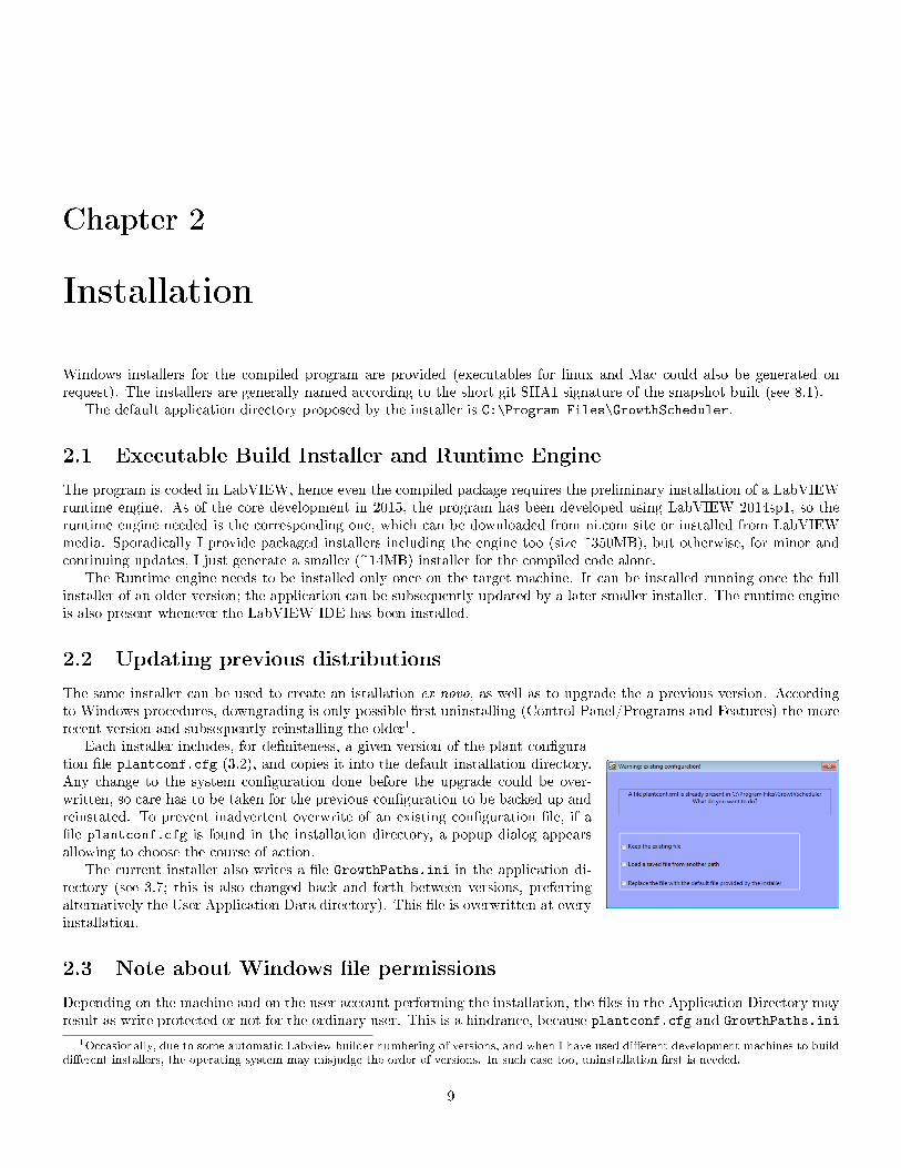
The same installer can be used to create an istallation ex novo, as well as to upgrade the a previous version. Accordingto Windows procedures, downgrading is only possible �rst uninstalling (Control Panel/Programs and Features) the morerecent version and subsequently reinstalling the older1.
Each installer includes, for de�niteness, a given version of the plant con�gura-tion �le plantconf.cfg (3.2), and copies it into the default installation directory.Any change to the system con�guration done before the upgrade could be over-written, so care has to be taken for the previous con�guration to be backed up andreinstated. To prevent inadvertent overwrite of an existing con�guration �le, if a�le plantconf.cfg is found in the installation directory, a popup dialog appearsallowing to choose the course of action.
The current installer also writes a �le GrowthPaths.ini in the application di-rectory (see 3.7; this is also changed back and forth between versions, preferringalternatively the User Application Data directory). This �le is overwritten at everyinstallation.
2.3 Note about Windows �le permissions
Depending on the machine and on the user account performing the installation, the �les in the Application Directory mayresult as write protected or not for the ordinary user. This is a hindrance, because plantconf.cfg and GrowthPaths.ini
1Occasionally, due to some automatic Labview builder numbering of versions, and when I have used di�erent development machines to build
di�erent installers, the operating system may misjudge the order of versions. In such case too, uninstallation �rst is needed.
9
2.3. NOTE ABOUT WINDOWS FILE PERMISSIONS CHAPTER 2. INSTALLATION
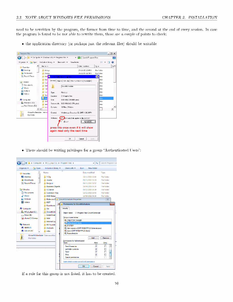
need to be rewritten by the program, the former from time to time, and the second at the end of every session. In casethe program is found to be not able to rewrite them, these are a couple of points to check:
� the application directory (or perhaps just the relevant �les) should be writable
� There should be writing privileges for a group �Authenticated Users�:
If a rule for this group is not listed, it has to be created.
10

CHAPTER 2. INSTALLATION 2.4. MULTIPLE INSTALLATIONS
2.4 Multiple installations
It could be convenient to have more than a single copy of the program installed on a computer. This has to be donemanually, duplicating the Application Folder, and thus is not tracked by the OS.
One case use for multiple installations is convenience of reviewing independently (o�ine) recipes and simulate theexecution of di�erent plans in di�erent copies of the program. There could be other strategies for that and we're not yet�xed on a de�nite scheme, see discussion in 7.
11

2.4. MULTIPLE INSTALLATIONS CHAPTER 2. INSTALLATION
12
Chapter 3
Operation
3.1 Program overview
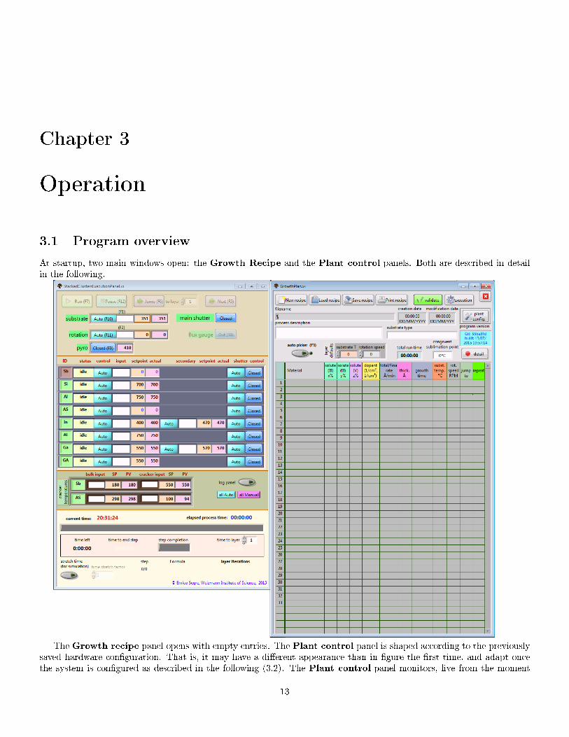
At startup, two main windows open: the Growth Recipe and the Plant control panels. Both are described in detailin the following.
The Growth recipe panel opens with empty entries. The Plant control panel is shaped according to the previouslysaved hardware con�guration. That is, it may have a di�erent appearance than in �gure the �rst time, and adapt oncethe system is con�gured as described in the following (3.2). The Plant control panel monitors, live from the moment
13

3.2. HARDWARE CONFIGURATION CHAPTER 3. OPERATION
it opens, readouts from the con�gured hardware, if present, or fake data, for simulation purposes. It can even be closed,
and retrieved again with the button �Execution� in the Growth recipe panel, without interruption of its fullrunning state. Closing the Growth recipe panel instead quits the program.
The casual user of an already con�gured plant, not interested in the details of the con�guration process, would probablyskip from this point to 3.3.
3.2 Hardware con�guration
In the intended work�ow, the hardware con�guration panel is seldom accessed, as it needs to be set up only once foreach plant, and changed only when cells are exchanged or recommissioned; periodically the e�usion performance may bemeasured and the rate con�guration may need to be corrected, but, all together, not as part of the everyday procedure.
The con�guration panel is modal, to prevent any other program action while the con�guration may bechanged. It is opened with the dedicated button on the Growth recipe panel.
The con�guration panel has two tabs, one for de�ning everything related to the e�usion cells (3.2.1), andthe other for con�guring about everything else, that is properties of hardware in the main growth chamber, and generalreadout intervals and timings (3.2.2).
3.2.1 Cell Con�guration
The left stack (refer to the �gures shown in the following paragraphs) de�nes general properties of each e�usion cell. Newentries are created by typing into the �elds of the next-to last element of the array, or using the right-click contextualmenu �Insert element� at any point of it.1
Each cell has the following global properties:
� a short identi�er (yellow �eld), which is used throughout the Material formulas (3.3.1.1); commonly, chemical elementsymbols are used;
� a long, free text description (light blue)
� an elemental type property, which can be III base, III solute, (IV) dopant, V (the roman number being the chemicalvalence group in the periodic table). The correct type rules how the element can be used in growth formulas.
� a cell kind, currently Single Filament, Double Filament or Cracker. Di�erent cell kinds have di�erent hardwarecomponents and need a speci�c di�erent con�guration subpanel.2
Pressing the con�gure button, the speci�c con�guration panel opens on the right. The button of the cell currentlycon�gured is highlighted in red.
In all systems we thought of, all cell shutters are driven by a single multishutter controller, which may or may not beresponsible for further controls like main cell shutters and actuators. The controls for setting the communication resourceand the device type of the shutter controller are placed above the cell list, the individual channel for each cell is set in itsparticular con�guration subpanel.
1Currently, Insert element resets all the detailed con�guration of the following cells, see related ticket2Currently, changing the cell kind resets all the detailed con�guration of the cell, see related ticket
14

CHAPTER 3. OPERATION 3.2. HARDWARE CONFIGURATION
3.2.1.1 Single Filament e�usion cells
A single �lament cell has a bulk heater, whosetemperature is controlled according to the e�u-sion rate (and hence the epitaxial growth rate)desired. The cells are periodically calibrated toassess the R(T ) dependence, which is usuallyassumed to be in the form R = a e−b/T . Theinverse formula T (R) is input. For generality,it is not limited to the form T = A/(B−logR);other expressions can be input. The syntax isthat of the LabVIEW formula parser.
It is customary to write growth formulas asdescribed in 3.3.1.1, where the element nameis postpended with a su�x indicating a prede-�ned rate. This su�x is free text, usually one�gure numbers are used. A table of prede�nedlabels and rates is �lled, where the resultingbulk temperature is automatically computed.
The prede�ned rates are binding if the cellis used for a base III element or for a dopant,but are only informative for a solute III, because in practice the rate of a solute III is computed and not a primary input.
The Look Forward Time is used during process scheduling to allow preheating and stabilization of cells before theiruse in the process. The logic is that a cell setpoint must be commanded at least LFT seconds before the cell is �rst used;and if the growth process is programmed with intermittent uses of a cell, the cell is brought to a standby state if the pauseis longer than 2LFT . (If a process is programmed with changes of the setpoint within a time shorter that LFT betweenintermittent uses, the setpoint is changed as soon as possible, and it is the responsibility of the writer of growth recipesto run judiciously into such case).
For the heater itself, the communication address has to be de�ned; moreover, the range temperatures and the temper-ature at which the cell is to be held at idle time (idle T ) and while standing between discontinuous uses in the course of aprocess (standby T ). At the moment the choice of two di�erent Eurotherm controllers for the heaters is o�ered; however,the communication to them is identical and coded as a single case. The controller list might be expanded in future if theneed arises.
15

3.2. HARDWARE CONFIGURATION CHAPTER 3. OPERATION
3.2.1.2 Double Filament e�usion cells
Double �lament cells are analogous to single �l-ament cells, with the presence of an additionalheater for the lip, having the same con�gura-tion parameters of the bulk heater. Duringgrowths the lip temperature is set as a func-tion of the bulk temperature, as expressed bythe lip formula.
3.2.1.3 Cracker e�usion cells
The e�usion rate of a cracker is determined bya valve position, and not by the temperaturesof the heaters. The prede�ned rates are thebreakpoints for linear interpolation, when anarbitrary rate is used.
The valve driver and communication ad-dress is chosen in the apposite subpanel. Im-plemented drivers at the present time are forthe older Veeco SMC (bisync serial), for the
newer Veeco SMC-III Flexcomm (modbus serial, as we haven't been able to use bisync serial, theoretically identical tothe former), and Riber AVP (modbus serial). A further option �manual� is provided out of no other choice. When that ischosen, the communication resource chosen is irrelevant.
The look forward time is taken into accountto change anticipatedly the valve setpoint, butenters otherwise there is no setting of valves instandby or idle positions.
Crackers have also two heaters, whose ad-dresses and temperature ranges have to beset. Di�erently than other cells, however, thesetemperatures can only be controlled manuallyin the execution panel and are not driven bythe growth process. Therefore, while the minand max temperatures have a safety meaning,the idle and standby temperatures are irrel-evant. For programming economy, the sameheater con�guration template has been usedas for the other cells.
16

CHAPTER 3. OPERATION 3.2. HARDWARE CONFIGURATION
3.2.2 Main and timing con�guration
The subframes of this tab have the following function:
Substrate Heater has the same con�guration mask as the cell heaters, for lazy programming uniformity. The idletemperature is that at which the substrate is sent at the end of a growth process; the standby temperatures isirrelevant.
Substrate rotator besides specifying the communication port and the type of the controller, the slew rate speci�es themaximal angular acceleration/deceleration, which the user may want to keep low in order to prevent unnecessaryimpulsive stresses and friction.
Pyrometer as one of the possible ways of reading it out has hacked to be using one Eurotherm A/D channel, the addressof that can be speci�ed.
If the controller or driver �eld of one of these devices is set to Manual (for shutters) or Unknown (pyrometer readout) orcustom (rotator), the communication parameters are ignored, and there is no risk of con�ict with other devices.
Engine query times state variables are periodically read, unless a write to the same controller is imminent. Thesecontrol allow to specify the relevant timings: with which frequency to read (the more, the more immediate indicationin the Plant Control Panel 3.5), and how much time each read is suppose to take at most (to cancel a read if ascheduled write is supposed to be sent before that time). There are presently four of such timing controls, as thechoice has been to use four engines (5).
Ramping update time How often the temperature of a ramping cell is recalculated. As the heaters are slow respondingobjects, it doesn't make exceeding sense to send temperature change commands more than once in every few seconds.
Prerun waiting time The guard time before starting a process, as described in 3.5.2.1.
3.2.3 Con�guration �les
On closing the panel, all con�guration changes are e�ected in the various parts ofthe program (fact which may invalidate the current recipe or settings), and the newcon�guration is written in to the default �le plantconf.cfg. The current logic isthe following. It can perhaps be changed in future, it has some drawbacks but it also its rationale and advantage.
� At program start, the default con�guration is read from the �le plantconf.cfg, which resides in the same directorythe same directory of GrowthScheduler.exe (or in that of GrowthPlan.vi, if the sources are tested in theLabview IDE).
17
3.3. GROWTH RECIPE PANEL CHAPTER 3. OPERATION
� Every time the con�guration panel is closed, the �le plantconf.cfg is overwritten, either that the con�gurationreally changed or not.
� The con�guration panel has in any event buttons for a) saving the current con�guration under any other name inany directory; b) load a con�guration �le with arbitrary pathname.
� It is useful and recommendable to keep safety copies of con�gurations at a given instant in time. To that extent theprincipal �le plantconf.cfg can be copied around wit OS action in a safe place, with the same or with a di�erentname; or the con�guration panel can be used to save it under another name.
� When a con�guration �le is loaded with the con�guration panel, the new con�guration is saved in plantconf.cfg.
As a matter of fact, the �le plantconf.cfg is not meant to be easily edited as text �le, externally by the user. Somereasoning is in 4.1.1.
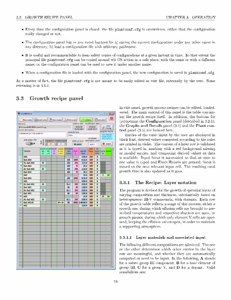
3.3 Growth recipe panel
In this panel, growth process recipes can be edited, loaded,saved. The main control of this panel is the table contain-ing the growth recipe itself. In addition, the buttons for(re)opening the Con�guration panel (described in 3.2.1),the Graphs and Details panel (3.4) and the Plant con-trol panel (3.5) are located here.
Entries of the table input by the user are displayed inblack font, derived values computed according to the rulesare printed in violet. The content of a layer row is validatedas it is typed in, marking with a red background missingor invalid entries, and computing derived values as datais available. Input focus is automated so that as soon asone value is typed and Enter/Return are pressed, focus ismoved to the next relevant input cell. The resulting totalgrowth time is also updated as it goes.
3.3.1 The Recipe: Layer notation
The program is devised for the growth of epitaxial layers ofvarying composition and thickness, substantially based onheterogeneous III-V compounds, with dopants. Each rowof the growth table re�ects a stage of this process, either agrowth one, during which e�usion cells are brought to pre-scribed temperatures and respective shutters are open, orgrowth pauses, during which only element V cells are oper-ated, keeping the e�usion valves open, in order to maintaina supporting atmosphere.
3.3.1.1 Layer materials and associated input
The following di�erent compositions are admitted. The oneor the other determines which other entries in the layerrow are meaningful, and whether they are automaticallycomputed or need to be input. In the following, A standsfor a solute group III component, B for a base element ofgroup III, C for a group V, and D for a dopant. Validpossibilities are:
18

CHAPTER 3. OPERATION 3.3. GROWTH RECIPE PANEL
1. BC binary layer with base III.Only the layer thickness is input. The growth rate of the layer is determined by the prede�ned rate chosen for B.
2. ABC ternary solid solution.Inputs are the percentage x% of A, and the layer thickness. The component B is present at (100− x)%.
3. AABC quaternary solid solution.Inputs are the percentages x% and y% of the two solutes A, and the layer thickness. The component B is presentat (100− x− y)%.
4. AC binary layer with 100% �solute� III.Inputs are the desired growth rate and the desired layer thickness.
5. AAC ternary solid solution without base IIIInputs are the desired growth rate, the layer thickness and the percentage x%. The fraction y% = 100− x% is �lledin automatically.
6. C, CC growth interruption.The only input is the desired growth (pause) time. In the case CC, the column for the percentage z% can be �lledso as to show an indicative value, but it doesn't a�ect any computation3.
7. rABC, rAAC ramped solid solutions (rA rAC and rA rABC are also possible though I understand not usedin practice)The concentrations of the ramped solutes start from the concentration of the corresponding component at the endof the previous layer, and vary linearly with height till a �nal value. The inputs are the same as for cases 2. and 5.,but solution percentages input are intended as those to be reached at the end of the layer.
8. BC:D, ABC:D, AABC:D, AC:D, AAC:D, 3-d doped layers.As the corresponding preceding cases, with the addition of the dopant. The additional input is the desired bulkdopant concentration, which is assumed not to a�ect the growth rate.
9. C:D 2-d doping (∆-doping).Inputs are the surface dopant concentration and growth time.
The convention is to display the formula with its constituents in that order, i.e. AlGa3As3 for case 2, rAlGa4As4 forcase 7, etc.
3.3.1.2 Material Picker
To avoid mistakes in inserting formulas, a modal popup picker is provided.The picker opens automatically whenever focus is in a Material cell in theGrowth table, if Auto Picker is on; otherwise it can be invoked with thebinding F3.
The buttons of the picker are generated from what de�ned in the cellcon�guration. The color of the buttons re�ects the role of the component:olive green for base group III components, light green for solute III, yellowfor dopants, fuchsia for group V. Components are chosen either pressing onthe buttons, or typing the letter and the �gure corresponding to the desiredcell and rate, e.g. typing C7 or 7C in the example shown in �gure to obtain Ga3 in the formula. Components can beentered in any order, the picker validates and normalizes the formula as it goes.
To replace a component previously entered with a given rate, with a di�erent rate (e.g. Ga1 with Ga2), it is su�cientto press the button for the new rate, or to type the new cross-code.
To remove a component from a formula, it is possible to press on a black empty cell in the relative column.
3I wonder if z% shouldn't result instead from the rates chosen, which are in �ux units anyway.
19

3.3. GROWTH RECIPE PANEL CHAPTER 3. OPERATION
Picker keyboard shortcuts
Return exits the picker, sending the constructed formula to the current cell in the growth table
Escape exits the picker, without passing the modi�ed material
Backspace removes the last component entered
Delete clears the current formula
3.3.1.3 Substrate rotation and temperature
They have to be �lled in for every layer. However, the default values written in advance into �layerdefaults� are proposed, as a convenience.
3.3.1.4 Looping (periodic structures, superlattices)
If a given set of consecutive layers is to be repeated a number of times, the cell �jump to� of the last layer of the set is tobe �lled with the number of the �rst layer of the set, and the �repeat� cell with the number of repetitions. All the �jumpto� cells of the member layers are highlighted in dark grey to mark the stretch. In MBE language, such repetition is saidto form a superlattice. A recipe can contain more than one non-overlapping repetition. Nested loops are allowed, even ifnot used in practice.
3.3.1.5 Keyboard shortcuts in the Growth Table
F3 on a Material cell, pop up the Material picker (unless the switch �auto picker� is toggled)
Enter, Shift-Right move to the next editable cell on row, or to the beginning of the next row
Shift-Enter, Shift-Left move to the previous editable cell
Shift-Up move to the editable cell directly above, or to the �rst editable cell on the right in the row above the current,if the cell directly above is not editable
Shift-Down move to the editable cell directly below, or to the �rst editable cell on the right in the row below the current,if the cell directly below is not editable
Shift-Insert, Ctrl-Insert insert a layer low at the before the current position
Shift-Delete, Ctrl-Delete remove the current layer row
3.3.2 Auxiliary recipe information
These �elds are saved along with the recipe:
Process description free text
Substrate type free text
Congruent sublimation point temperature in °C. The grown crystal has to be maintained under element V atmosphereas long as the substrate temperature is higher than this value, as it goes in 3.5.2.6.
3.3.3 Load, save, print recipe
By self-explanatory buttonry.Recipe �les themselves are tab-separated text �les, plainly re�ect-
ing the process information and Growth table content, as input. Thedefault extension of recipe �les is .rcp.
When an existing recipe is loaded, its modi�cation date is set to the current time.For �exibility and device independence, Print generates a temporary html �le with a colorized rendering of the recipe,
and opens it in the default browser. From there, it can be printed or saved using the browser's own commands.
20

CHAPTER 3. OPERATION 3.3. GROWTH RECIPE PANEL
3.3.4 Process compilation and veri�cation
On one hand, the input validation of the table rows doesn't guarantee that the completegrowth process is feasible, because of constraints on the allowed temperatures of the cellsand because sudden rate changes on heated e�usion cells cannot take place. On the other,the table content is not yet in the form of a process schedule.
Compilation and process validation happen when the �validate� button ispressed, or when focus is brought to the Plant control panel (3.5) or to theGraph andprocess details panel (3.4). In the current program implementation compilation is notimmediate, and moreover it is supposed to bring up warning dialogs like those in �gure,for unrealizable recipes. Because of this, compilation is not launched automatically foreach change in the table content.
The �validate� button is grey if the recipe has been modi�ed but not validated, yellowwhile it is validated, green if it is compiled and valid and red if it is compiled and invalid.Invalid recipes can be executed, but the results may be not those prescribed by the recipetable�cells may not reach in time the temperatures and rates prescribed, temperaturesmay be clipped to the ranges con�gured for the cells, layer thicknesses may be di�erentthan what asked, etc.
Layer repetitions (3.3.1.4) demand that the growth process is unrolled, to determine the correct antecedent and followersof a certain iteration of a given layer. This is re�ected in reporting both the step number and the corresponding [layer]number, as displayed in the warning messages here and in the Rate table below (3.4.4).
21

3.4. GRAPHS AND PROCESS DETAILS PANEL CHAPTER 3. OPERATION
3.4 Graphs and process details panel
The button �Detail� on theGrowth recipe panel opens a new window with four tabs. These tabs where initially conceivedas a graphical veri�cation aid during development, and haven't all been polished for clarity. All the information shownrefers to the last recipe validated; however, opening or bringing the focus to this window triggers a validation of the recipe(if it was changed since), to actualize the content.
3.4.1 Cumulative thickness tab
This would be a graph of the total growth thickness, or of the step timing as a function of either the growth time orthe step number. It is not the most useful graph, nor it is accurate in the case of ramped layers, as it shows a stepwiselinear approximation of the thickness rather than the real growth curve.
Some general interface features are common with the next two tabs:
� the data used as abscissa (e.g. step or growth time) and ordinata can be selected by pull-down menus by the axes;
� scale limits for abscissa and ordinata can be typed into, if the axes ane not set for Autoscale (which is changed byright click menu on them)
� A cursor can be dragged, to inspect the numerical values of the curve. This is a standard labview widget; the position
of the cursor can also be set numerically by typing it in the cursor legend (which needs to beopened, showing + on its left, clicking on that column)
� the cursor automatically follows the process, during execution;
� The cursor can be dragged only if the right graph tool is selected ( ). The middle tool allows zoomingthe graph by point and click, if Autoscale is unset.
22

CHAPTER 3. OPERATION 3.4. GRAPHS AND PROCESS DETAILS PANEL
3.4.2 Setpoints and rates graph
This graph is a bit more useful. By default it shows only traces of the cells used by the last validated recipe; tracesfor any cell can be shown/hidden with the radio buttons on the left of the graph.
Continuous lines represent �ux from cells momentarily in use, whereas dashed lines give the setpoint of equivalentrates at time the cell shutter is closed. Either the setpoint of the rate can change when a cell is not in use, if the schedulerequires an anticipate preparation.
3.4.3 Cells use graph
23

3.4. GRAPHS AND PROCESS DETAILS PANEL CHAPTER 3. OPERATION
This panel shows when cell shutters are closed/opened along the process as a digital graph, and is not particularlyreadable nor useful, admittedly.
3.4.4 Rate table
This shows, step[layer] by step and cell by cell, the prescribed e�usion rates Ri at the beginning and Rf at the end ofthe layer (the values may be di�erent for ramped layers), as well as the cell setpoints Seti and Setf , which can either bebulk temperatures for �lament cells, or valve positions for crackers. The information displayed parallels the one graphicallyavailable in the Setpoints and rates graph (3.4.2), except for not showing the time, and the evolution in the course of astep.
Entries corresponding to cells unused in a given layer have a gray background; entries of cells used have cyclical pastelbackgrounds, as a pure guide to the eye. Out of range temperatures are marked in blue if the request was too low andred if too high, and clipped to the acceptable range.
24

CHAPTER 3. OPERATION 3.5. PLANT CONTROL PANEL
3.5 Plant control panel
Once a recipe is validated (3.3.4), the cells required are highlighted by a lighter gray background.
3.5.1 Manual control
3.5.1.1 Keyboard shortcuts in the execution panel
In setpoint input �elds (substrate rotaion, temperature, cell main and secondary setpoints, cracker temperatures), numberscan be typed and edited (e.g, the cursor is moved back and forth with Left/Right, text can be selected) before the inputis set into e�ect.
Enter, Return sets the value in the input �eld. A popup dialog appears if the resulting value is out of range (for heaters).
Up/Down Increase/decrease the value of the current setpoint of one unit, and immediately e�ect. A popup dialogappears if the resulting value is out of range (for heaters)
Otherwise:
25

3.5. PLANT CONTROL PANEL CHAPTER 3. OPERATION
F1-2, F5-F12 toggle various buttons, as indicated in the respective labels. F1 and F2 bring the typing focus in thecorresponding input �elds; all the other leave the focus in the current input �eld if it was already in one.
Escape abort a running process
3.5.2 Process execution
3.5.2.1 Starting the growth
In absence of any other more sophisticate scheme for controlling adequate pre-heating of all cells (with preparation sequences which may be special for delicatehardware), the start of a run simply initiates a countdown before the �rst layer.The countdown time is set in the general plant con�guration (3.2.2), and the initialwaiting phase can be skipped iof the operator sees that the plant is in good orderto start. The process can also be aborted at this point, if something turns out tobe not in order, or if the process was started erroneously.
3.5.2.2 Process running
The cell status according to the schedule (idle, standby, preparation, temperature reached, ramping) is shown by the nameof the cell. The background turns to fuchsia when the temperature is o� of more than 1◦C from the setpoint.
3.5.2.3 Automatic/manual status of a control
When not executing a process, the state of these buttons is indi�erent to the immediate control. During a growth processinstead, any control in Auto state is driven by the requirements of the process. To override them, the control has to betoggled as Manual. The Manual state is persistent until not resetted to Auto. That is, advancement of the process won'tchange setpoints of any control set in Manual mode, until that is not reset to Auto.
To be clear, setpoint changes are commanded at precise points of time during the execution of the process. They arechange events and not values of status. When a given control it is set back to Automatic, it won't immediately reset tothe value that it should have taken if it had been earlier Auto; it will only change to the next process-dictated value indue time.
3.5.2.4 Pause
During pause:
� all cell shutters but those of group V elements are closed. Group V elements are left open to maintain a protectiveatmosphere.
� timers are frozen at the point reached
� no setpoint is changed automatically, but any control can be changed like in immediate execution mode.
Other properties of the process in execution persist; for instance it is not allowed to change the plant con�guration, andthe growth recipe can be edited only past the current layer.
3.5.2.5 Skipping steps
There are two buttons for advancing the process and skip to a later point of the schedule:
Jump the process jumps to the beginning of the desired layer in the growth table. If the destination is within a super-lattice, the jump is implicitely to the �rst iteration of that layer. It is allowed to jump to a destination layer beforethe one currently executing, even if that may be of little practical use; that it is possible is helpful in debuggingsimulated processes. There is also no enforced limitation such that valid destinations may only be the �rst layers ofa superlattice.
Next goes to the following process step, which may happen to be the next layer during a linear process, or the beginningof the next iteration of a superlattice, if called on the last layer of a periodic sequence.
26

CHAPTER 3. OPERATION 3.5. PLANT CONTROL PANEL
There has been no request and thus there is no provision for jumping to an arbitrary time in the middle of a given layer,or to jump to the beginning of the previous step. I assume anything the like just doesn't make practical sense.
3.5.2.6 Process termination
Both on normal process end and on abort, the substrate heater is sent to its idletemperature, and all cell shutters are closed, besides that of the element V cell(s)used in the last step executed. The plant then stands by, till the substrate hascooled down below the congruent sublimation point speci�ed in the recipe (3.3.2).Only at that point the last shutter(s) are closed. The condition is shown in a modaldialog, which o�ers the option of terminating abruptly nevertheless.
3.5.3 Simulated hardware
Hardware which is not identi�ed as online at programstartup is evidenced (so to say) by bleak dirty copper col-ored labels, like in �gure; functional hardware by greenlabels. Grouped entities may be labeled as absent if com-munication attempts with one of their components failedat startup. Thus, e�usion cells are marked as bad if eitheror all of their heaters, of the shutter, are not reached.
For development purposes it has been very useful todisplay fake data for absent hardware, somehow related tocon�gured limits and process setpoints, plus random jitter.
Limitations:
� there is no option for rescanning hardware and check-ing if hardware temporary o�ine at program startupis later available, or vice versa;
� there is no indication of hardware which falls o�inetime after having been connected to at startup
� simulated readouts, along with real readouts, with-out a clear delineation of a simulation mode may beconfusing.
3.5.3.1 stretching (actually, accelerating) processtime
This is an option which is useful for debugging and quickcheck of the scheduling sequences. When on, it is possibleto accelerate (or decelerate) the process clock by an arbi-trary factor. The e�ect while running in simulation mode isthat of accelerating all animations; it is quite meaninglessand probably disrecommended to use this modality withreal hardware, for two reasons:
1. large stretch factors will increase the communicationrate with devices, leading to communication errorswhen too high;
2. not only layer heights would be proportionally de-creased, also preparation times would become tooshort; accelerating the process time is obviously nota way to scale down sizes, if that ever had any sense.
27

3.6. LOGGER CHAPTER 3. OPERATION
3.6 Logger
The logger window is opened by the dedicated button in the Plant control panel. It is accessory, and besidesbeing the place for de�ning once for good the process log directory (3.6.1), it is mostly used only for debugging.
The idea behind it: the whole program is compartimentalized, and the Plant control panel sends execution messagesto a certain set of execution engines (see 5). Those in turn send back some acknowledgment and some readout messagesto the GUI; the GUI interprets them and reacts according to its status. The logger panel allows to inspect the stream ofthese messages, �ltering out only some kinds of, as checked in the column at the left of the terminal window.
3.6.1 Automatic process log
For that to happen, a default logs directory has to be selected once (and is remembered subsequently across sessions) inthe logger panel. These logs are tab-separated text �les with default name (same as the recipe �le) and extension (.rec),like
Process No.: simple_ramp
Start time & date: 22:31:49 16/07/2015
======================================
CRACKERS
Sb bulk=101°C cracker=118°C
AS bulk=49°C cracker=62°C
======================================
Time Layer# Sb Si Al AS In AL Ga GA subst. pyro. rot.
00:00:00 1 1 C 701 C 990 C 90 O 401 C 750 C 871 O 550 C 299 926 2.2
00:01:20 2 0 C 701 C 989 O 91 O 401 C 751 C 872 O 550 C 300 564 2.4
00:02:24 3 0 C 700 C 989 O 90 O 400 C 750 C 871 O 550 C 299 554 1.6
The content of the process log �les is �xed, and independent of other settings in the Logger panel. The cracker temperaturesreported are those at the beginning of the growth. Lines are added to the �le as long as layers start execution; times inthe �rst column are scheduled process times (don't re�ect manual pausing if there was such). The temperatures/setpointsand shutter stati reported for each layer line are the �rst values read after the start of each layer.
28

CHAPTER 3. OPERATION 3.7. SESSION PARAMETERS
3.6.2 Raw events log
Raw log �les are a text dump of the events shown in the window, as �ltered by the left list. Raw event log �les areintended mainly to be used for debugging purposes, or for timing analysis, with external textual tools to be devised adhoc and per need.
3.7 Session parameters
In addition to the hardware and system con�guration is stored in the �le plantconf.cfg in the Application Directory(3.2.3), the following settings are remembered across sessions:
� the last path used for process log �les
� the last path used to load/save recipes
� the last path used to load/save con�guration �les
and are all stored on exit in the �le GrowthPaths.ini in the Application Directory. [the scheme might be changed infuture to support multiple plant con�gurations]
29

3.7. SESSION PARAMETERS CHAPTER 3. OPERATION
30

Part II
Design philosophy and implementation choices
31


In what follows I attempt to note down some of the principles which led to the make of the present code, for futurereference. I don't aim to a complete description of the code workings; for that I hope that either the source �les orga-nization and naming, or the code itself are sort of self-explanatory. It is certainly wishful thinking, but a complete codedocumentation, for a codebase which may still change, would be sort of out of place.
The development of the code certainly su�ered of inadequate initial formalization of its requirements, and of subsequentfeature creep. Laying out the development plan was in a way a red queen race, attempting to include a priori �exibilityin anticipation of possible future requests. With the risk of early overgeneralization.
The code itself has to accommodate for:
� �exibility in con�guration with di�erent hardware, interchangeable in time or between di�erent operated plants
� abstraction of the operation from the actual hardware employed, which may sometimes be di�cult to achieve (6.1)
� immediate SCADA of the hardware, with convenience shortcuts
� editing growth process recipes, which are laid out according to a number of notational conventions, and must satisfya number of operational constraints; editing must be assisted, convenient in �lling up derived data; and as much aspossible validated. Recipe validation and in general error handling was (stupidly) considered an unnecessary luxuryin the requirements phase, obviously a distorted attitude.
� execute process cycles in supervised mode, with reliable timing.
33

34

Chapter 4
Data�ow and internal representations
In order to avoid a dependency hell, I introduced a multistage internal representation:
1. the cell con�guration de�nes the available elements and the role they can take in a material formula (4.1)
2. the material formula determines the assisted editing of the layer of the growth table
3. the layer line and its relation with its antecedent and followers (unrolled wise) determines the sequence of hardwaresetpoints needed to execute a process. The layer table is translated into a sequence of process steps (4.2)
4. The process steps computed from the growth recipe are downloaded to the main execution engine, the Execution-EventEnqueuer, which �rst of all translates it into four di�erent arrays of schedule elements (4.3), destined to fourdi�erent hardware engines (5)
5. The ExecutionEventEnqueuer is a state machine caring for the execution status of the process, like start, stop,pause.
6. When the process is executed, the ExecutionEventEnqueuer polls the process timer every 5ms, and dispatchesexecution messages to the hardware engines. These messages are writes, if scheduled events falling in the time slotare found; or periodical reads, when time for them is ripe.
7. To mix up enough things, communications between the engines and the GUI is implemented via several messagepassing queues:
� the Plant control GUI communicates both with the ExecutionEventEnqueuer and with the executioners viaa message passing queue, the GUICommandQueue; care is taken so that only one and only one among the mainengine and the executioners1 consumes each possible message.
� the ExecutionEventEnqueuer sends commands (scheduled events) to the four hardware engines, via four dedi-cated queues
� each of the �ve reports back to the GUI via an EngineResponseQueue. The GUI is the only consumer of theseresponses, but duplicates them on reception to a further queue consumed in turn by the logger.
4.1 From cell con�guration to picker
The plant con�guration structure is stored as a cluster of:
� an array of E�usionCells
� a cluster of de�nitions of main objects
� a cluster of timings
1pun intended.
35
4.2. FROM GROWTH TABLE TO PROCESSSTEPSCHAPTER 4. DATAFLOW AND INTERNAL REPRESENTATIONS
4.1.1 Format of the plant con�guration �le
Early in devising what format to use to save con�gurations, I decided to go for �xml dump of whatever everything�.This was a working choice, especially at a stage where it was completely unclear what kind of hardware is part of theplant and how it is hierarchically related, and which parameters of it constitute a con�guration. Within the program thecon�guration structure organized itself as an heterogeneous cluster, and a mindless xml dump was at least a solution. Notfree of maintenance issues, though:
� the con�guration �le is all text, but for programming convenience it is written in such a complicate way that it isquite di�cult to edit it sensefully in a text editor
� As of now, the project includes a plantconf.cfg (thus if you download a zip source it is in there), and the installersI create also copy it in the destination directory. Thus, your custom created con�gurations are de�nitely going tobe overridden, unless you create a safety copy.
� It is becoming rarer lately, because the design is converging, but not impossible, that if version after version I haveto alter the structure of the con�guration, old con�guration �les won't load in new version, or load only a part ofthe parameters. One such change could be, for example, adding a �ag "delicate" to crackers which need a slow sleepprocedure (issue #57).
� In case of old con�gurations incompatible with new programs, I may be able to adapt the �les for the new needs,but with some e�ort, and best if I'm only one version behind. I really haven't yet thought at a way to automaticallymaintain backward compatibility of such �les.
� Because of the identi�cation of the cell con�guration with the array CellProperties, the con�guration ends upcontaining some physical, contingent information as part of it, such as PhysicallyPresent and actual setpoint values.
Later in the development, i.e. with commit 7120745, I phased out xml con�gurations in favour of the new compact .cfgformat.
What lead to that:
� xml con�gurations were an easy solution (just formatted dump of the labview structure de�ning the components ofthe plant, using a built in tool), but were overbloated, and included not only con�guration parameters but also statevariables (presence, setpoint).
� serialization is not trivial, because the alternatives considered (native labview Json, JSON LabVIEW, AQ Lineator)are inadequate. the native Json is extremely limited in types of data handled; json-labview does a very good job inrecursively serialize (variant) data down to its components, but handles the serialization of OO objects only if theirclass are declared as children of a Serializable superclass, which involves some code changes; and more importantly,it does not provide any mechanism to deserialize the objects back to their structure without extra coding; and theLineator does not provide a particularly compact output.
So I tediously created my own set of serialization functions for every possible component of the big PlantCon�gurationcluster. Where I could, I coded a single format string good both for the Con�gToText and TextToCon�g methodVIs, to concentrate changes in a single place. The choice adds the overhead that whenever the need for changing thecon�guration structure arises, the proper methods have to be updated too.
The result is a con�guration format in which each object corresponds to one line of the �le, inspired by Json but muchmore rigid (to avoid a true parsing, it's only a formatted string scan) and compact. The advantages are compactness,terseness and hence better readability, and absence of spurious state variables.
4.2 From growth table to ProcessSteps
The best labview widget to represent the growth recipe was the Table. However Labview Tables are limited in that theyonly support text content, have limited and �xed editing bindings, which are overridden with lots of work and side e�ects,and are very slowly decorated.
Everything depends on itself and its mother's ass.A line of the growth table includes only information about the components of that layer, and moreover some timing
information whose signi�cance depends on the composition, whereas the execution of the process needs to know exactly
36

CHAPTER 4. DATAFLOW AND INTERNAL REPRESENTATIONS4.3. FROM PROCESSSTEPS TO SCHEDULES
what to do with all components of the plant: what to do with all cells, when to change temperature setpoints, alsoaccounting for preheats and idling. Furthermore, these cell settings may di�er in relation to a layer being grown the �rst,a repeated or the last time within a superlattice.
For these reasons, it was convenient to introduce in the program an intermediate translation of the growth table as anarray of ProcessSteps. Superlattice repetitions are �rst of all unrolled, so that the correspondence {layer,iteration}−→stepis resolved.
4.2.1 numeric representation of the growth table
The growth table was designed using the labview table widget, as it was the only practical way to build a tabularediting mask with some chance of moving focus programmatically, colorize and format entries programmatically, and soon. However, its content is the text which is displayed and nothing beyond. Where an entry is a computed number,truncated to few signi�cant digits for display convenience, that could become a problem if the number is further used incomputations. Truncation errors may propagate. Ways out of the situation may be:
� associate a parallel numeric array which mirrors the table at full precision; it will be a lot of work to keep it in strictsync with all the table editing actions; many editing actions will produce a �oating result, which is inserted in themirror, and reformatted back to the table.
� at the moment of compiling the table into ProcessSteps, instead of blindly reading the cell string, recompute allderived numbers using again the machinery which produced them, line per line according to the material and itsrules. That may mitigate or perhaps even circumvent the problem.
4.2.2 the class ProcessSteps
Each ProcessStep is a cluster detailing:
� corresponding role in the Growth table: original layer, formula, time of start and end layer growth
� general scalar e�ects of the layer, like thickness, rotation speed, substrate temperature
� derived rate information, i.e. growth rate of the base III element, total growth rate at the end of the previous stepand at the end of current step: they all enter in formula computations and operational cell settings (previous ratenotably for ramping layers)
� identi�cation (indices) of solute III cells used and component rates demanded from them
� an array detailing for every cell of the plant: whether that cell is in use (=shutter open) in the step, the requiredinitial and �nal rates and control setpoints, with in range �ags.
� an array, detailing, for every cell of the plant, a vector of (process) times at which rates, setpoints and cell statushave to be changed. Unused cells list anyway an idle setpoint at the initial time of the layer; this avoids tediousstatus bookkeeping when step hopping during process execution.
The array of ProcessSteps is built from the growth table in a number of parsing steps inGrowthTableToProcessSteps.vi.
4.3 From ProcessSteps to schedules
The class GeneralSchedule has a header with schedule time, corresponding growth table row and process step, and anaction �eld, set or get. To limit expandability simplify, both the hardware writes and the periodical reads are implementedas schedule events dispatched to the engines, and the action �eld determines the behavior.
This class has three children with speci�c properties relevant to each engine: the ShutterSchedule has a boolean arrayof shutter conditions, the CellSchedule has rate, setpoint, cell number and cell use; the same ScalarValueSchedule is usedfor substrate rotator and temperature.
37

4.3. FROM PROCESSSTEPS TO SCHEDULESCHAPTER 4. DATAFLOW AND INTERNAL REPRESENTATIONS
38
Chapter 5
Execution engines
with the questions always in the background - why didn't I use the DSC module (because it is not available for linux,precondition for my steady development pace), whether did I reinvent the wheel with a custom set of execution engines(now what, recipe execution with all its constraints could have been handled with a standard tool?), why don't I connectwith an historical database (which? that which comes with DSC, what comes nowadays? SQL? a microsoft product?).
As long as events to be logged are a subset of those returned to the GUI queue by the execution engines (see Report-edEventsLogger.vi), though, there may be some basis for neat development.
5.1 Realtime
Reliable and repeatable growths clearly require determinism in time. Nevertheless, it would seem that the acceptablejitter in the timing of shutters could even be of the order of 100ms (comparable with the action time), and that of heaterseven longer. Previous anecdotal evidence (both on programmer's and user's side) reported it as achievable with di�culty,and only under draconian safeguard measures, on the demanded desktop, non RTOS.
The proper handling of the realtime requirement would require separation between the GUI and the time criticalparts, with the latter running headless on a separate realtime target, and proper intercommunication between the two.The present design of the program has taken that into due account, with the creation of self-su�cient engines. However,the provision for separation is not yet complete, as the engines communicate with the GUI through queues, whose scopeis the single Application instance. The future move allowing detached run of the engines on a separate target would be totransform the queued messaging into some other, probably network based, communication mechanism.
Resource separation between GUI and engines is also not complete, as initialization is done by the GUI (namely thePlant control panel at startup and when detecting con�guration changes). Partially, for the reasons in 6.1; partiallybecause (re)initialization could be implemented better.
As for on the road performance, anyway, some analysys of the log timings has shown a jitter in fact down to a fewms, so that previous concerns seem currently non-issues. Computer powers may be larger than in previous incarnationsof the control system; anyhow the present program has been seen using only a few % of the available cpu power, and inaddition all the engine VIs have been assigned as running at �time critical priority�.
39

5.1. REALTIME CHAPTER 5. EXECUTION ENGINES
40

Chapter 6
Adding further hardware and functionality
Tip when changing the structure of the system con�guration (e.g. adding new members to the global con�guration,changing the structure of a member, etc.): if structural changes are made, the old plantconf.cfg �le will be out of syncwith the new con�guration structure, an error will result when GrowthPlan.vi attempts to read it, and an empty orincomplete con�guration will result. In order to preserve as much as possible of the existing con�guration, a workable wayto develop structural changes is the following:
� run SystemCon�gurationPanel.vi directly;
� load the existing plantconf.cfg; this reads in values for all controls;
� abort the VI with Ctrl-.
� code the required changes;
� as soon as SystemCon�gurationPanel.vi is runnable again, run it and save a new, format-augmented plantconf.cfg.
To this extent SystemCon�gurationPanel.vi needs not to be modal, or it would remain modal also aborted. OTOH,on the road the user should be prevented to do anything other than con�guring while the panel is open. That is therationale for 06ac4ef.
6.1 Issue: Double (triple) a�liation for devices
The design pattern su�ers from the following:
� some hardware devices are compound devices, e.g. cells consist of heaters, a shutter, a valve; the main chamber�itdepends how it is seen, if all is "manipulator" or further subdivided in Pyro, Substrate,...
� component devices are physically grouped in a way that crosses the compound device boundaries: all Eurothermsare on the same 485 line (and additionally analog readouts on Eurotherms), all shutters (or groups of) are handledby the same controller, together with other movimentation.
� execution engines are responsible for yet another cut of devices (e.g. all cell temperatures and setpoints, substratetemperature and pyro readout but not pyro shutter or rotator, all shutters together)
The problem with this organization is that competences are confuse. For instance initialization and deallocation ofresources cannot take part in engines, because the cut of the engines is di�erent than the hardware grouping; resourceprotection happens via globals and semaphoring, not via encapsulation; adding new kind of devices may turn into a jigsawe�ort.
41

6.2. CASE STUDY: ADDING A NEW VALVE CONTROLLERCHAPTER 6. ADDING FURTHER HARDWARE AND FUNCTIONALITY
6.2 Case study: adding a new valve controller
In a later stage, porting the application to Compact 21, it turned out that we weren't able to drive the Veeco SMC-IIIcontroller via the serial BISYNC protocol like the older Veeco SMC on MBE, and we moved to the option of modbusRTU. The augmentation is an exemplar case, because it is self contained. We have only one class Valve, one attributesof which was the ValveController typedef. Here the distinct code driving di�erent hardware is not implemented as one-per-kind subclasses, but simply as conditional code in each of the method VIs for the general class Valve, selected by theValveController attribute. The work to be done hence amounted to:
� add a new item in the ValveController typedef
� go through the relevant method, InitializeValve, and three accessors implementing real communication with hard-ware, that is ReadValvePosition, ReadValveTarget, WriteValveTarget, adding the code for the new case
As the Valve class de�nition itself didn't change, there was no need to propagate the changes to the (only) con�gurationpanel accessing it, the Cracker panel. However, the change in typedef enumeration caused a mismatch in the existingcon�guration �les, which needed manual revision to reinstate the correct settings. As the con�guration panels persistedacross the change, that was easily done in the GUI.
42
Chapter 7
Multiple con�gurations
7.1 Con�guration and session �les
My rationale for having two di�erent �les plantconf.cfg and GrowtPaths.ini is that one is the proper plant con�guration,and this should be changed only by the responsible administrator, while session settings like the last directory chosen canwell depend on each user. I don't know if it re�ects the present way of work, but in principle many users could have theirown accounts on a plant control computer, whereas only one authorized administrator is allowed to tamper with sensiblehardware con�guration like the number of cells or the addresses of the devices.
Codewise, at some stage I also had reasons for storing the two sets of data in two di�erent structures and handlingthem in di�erent parts of the program, but now that is blurred.
7.2 Multiple plants on a single computer
Now whichever scheme has to work on three computers as of now, where one of them needs to have an easy way ofaccessing two di�erent con�gurations. The doubled application directory was a possible solution, but I could envisagealso others: a single application with a prominent drop-down menu for chosing the plant (how do we know what are theoptions, and change them? Perhaps at startup some directory "Possible Con�gurations" is scanned. What would be thedefault, etc.) (I envisage that you might even want to store historical con�gurations for a given plant, i.e. say be able toopen an old recipe with the con�guration the plant had years ago, in order to check what was going on).
Another solution could be keeping a single application directory, but copying twice the executable with di�erentnames; use as default con�guration not plantconf.cfg but NameOfTheExecutable.cfg or something the like; revert thatGrowthPaths.ini is written to the User Application directory, also with a name composed with the name of the program.This way we could both handle di�erent permission levels, di�erent settings for di�erent users, and di�erent plants, withthe slight waste of having two copies of the executable and having to do that manually after the installation. The hindranceis that also the �le MBEGrowthController.ini containing the default font sizes has to be renamed accordingly. I couldwrite a post-installation script for that; there is no end.
Another possible option is to set up things so that clicking on the (shortcut to the) con�guration �le, the executable(a single copy of) opens loading that �le. I'd have to study how to do it smoothly in Labview.
43

7.2. MULTIPLE PLANTS ON A SINGLE COMPUTER CHAPTER 7. MULTIPLE CONFIGURATIONS
44

Chapter 8
Source control and build
8.1 Git repository
Development has been source-tracked all the way through. One copy of the source repository is at the WIS-internal projectrepository, accessible only within WIS �rewall. It is a private project, so sign in on the WIS gitlab server for access �rst,and then ask Enrico to be named as member, in order to see it.
LabVIEW source �les are stored with compiled code removed, to prevent useless binary divergence. Some instrumentmanuals, some requirements documents and the sources of this manual are also stored in the same repository.
8.2 Issue tracker
WIS-internal issue tracker. As part of the above, only accepted members, with minimal status of Reporter can writetickets.
8.3 Building and distributing the application
There is a technical issue about building the executable application with the labview compiler, documented in issue #56.Labview crashes apparently because of the way chosen to display the software revision and the build date, i.e. getting onthe main window the information from an ancillary subVI which is programmatically �lled with that data and saved asprebuild step. The crash seem to be done to the collision of former and new version of this VI in the compiled objectscache, and the action required is to clear it after unloading the project from memory. To partially overcome that loophole,a build script external to the project has been created, which also cares for additional steps like renaming the �nal installerre�ecting the git revision id. Such steps themselves wouldn't be possible with the facilities of the project build. Clearingthe object cache though may be still needed before running that script.
45

8.3. BUILDING AND DISTRIBUTING THE APPLICATION CHAPTER 8. SOURCE CONTROL AND BUILD
46

Chapter 9
Alternative ideas
First, I'm not at all convinced that functionally equivalent software doesn't exist, either commercially or as, less likely,open sourced. In fact I'm aware of one open source example in VB, Faebian Bastiman's (seen april 2015). Commercialproducts include Veeco's Molly, Riber's Crystal.
Argument could be on convenience of use, or suitability for the purpose, for the in-house conventions and habits. Ihave uderstood that here the orientation is for the execution of many one-of-a-kind processes, with the option of on-the-�yadjustments, hence the stress on the convenience of input of the recipe, rather than in�nite repetition of an industrialprocess, for which it is a�ordable that the recipe is programmed only once in a while, even in a rigid and less convenientform.
I speculate that the labview infrastructure put together to control the hardware could be augmented by a scriptingmodality of control.
47