mbe*/* mini-bridger express three-output amplifier · pdf filethree-output amplifier...
TRANSCRIPT

M B E * / *
M i n i - B r i d g e r E x p r e s s
T h r e e - O u t p u t A m p l i f i e r
I n s t a l l a t i o n a n d O p e r a t i o n M a n u a l
S T A R L I N E 2 0 0 0 S E R I E S®
20
20
20
20
ASSEMBLED IN MEXICO
POWER
MBE
A
J
S G87
75
E
K
REFER TO
MANUAL FOR
FUSE VALUES
CHECK VOLTAGE
SELECTOR
REFER TO MANUAL
L
-20dB
-20dB
JXP 4
JXP 2
JXP 3
ADU
-20dB
-20dB
-20dB
-20dB
JXP INJXP COMMON
JXP ADU -20dB
JXP 4JXP 3
-20dB
JXP
MAN
TDU
ADU
IN
PORT 3
PORT 2
PORT 4
L
H
L
H
L
H
MAN
DRIVE
UNIT
BODE
MDR
JXP
THERM
MINI-BRIDGER EXPRESS
RTN
EQ
H
CAUTION:CONTAINS PARTSAND ASSEMBLIESSUSCEPTIBLE TO
DAMAGE BYELECTROSTATICDISCHARGE (ESD)
dB
FWD
EQ
CautionCautionCautionCaution
These servicing instructions are for use by qualified personnel only. To reduce the risk of electrical shock, do not perform any servicing other than that
contained in the Installation and Troubleshooting Instructions unless you are qualified to do so. Refer all servicing to qualified service personnel.
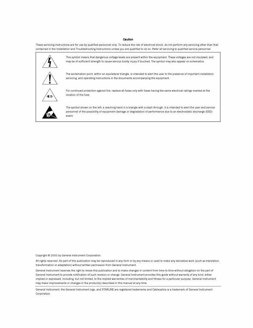
This symbol means that dangerous voltage levels are present within the equipment. These voltages are not insulated, and
may be of sufficient strength to cause serious bodily injury if touched. The symbol may also appear on schematics.
The exclamation point, within an equilateral triangle, is intended to alert the user to the presence of important installation,
servicing, and operating instructions in the documents accompanying the equipment.
For continued protection against fire, replace all fuses only with fuses having the same electrical ratings marked at the
location of the fuse.
The symbol shown on the left, a reaching hand in a triangle with a slash through, it is intended to alert the user and service
personnel of the possibility of equipment damage or degradation of performance due to an electrostatic discharge (ESD)
event.
Copyright © 2000 by General Instrument Corporation.
All rights reserved. No part of this publication may be reproduced in any form or by any means or used to make any derivative work (such as translation,
transformation or adaptation) without written permission from General Instrument.
General Instrument reserves the right to revise this publication and to make changes in content from time to time without obligation on the part of
General Instrument to provide notification of such revision or change. General Instrument provides this guide without warranty of any kind, either
implied or expressed, including, but not limited, to the implied warranties of merchantability and fitness for a particular purpose. General Instrument
may make improvements or changes in the product(s) described in this manual at any time.
General Instrument, the General Instrument logo, and STARLINE are registered trademarks and Cableoptics is a trademark of General Instrument
Corporation.

MBE*/*
Con ten t s
Sect ion 1
I n t r oduc t i on
Using This Manual .......................................................................................................................1-2
Related Documentation ................................................................................................................1-2
Document Conventions .................................................................................................................1-2
If You Need Help .........................................................................................................................1-2
Calling for Repairs ......................................................................................................................1-3
Sect ion 2
Ove r v i ew
Assemblies and Modules ..............................................................................................................2-3
Housing.......................................................................................................................................... 2-3
Power Control Options ..................................................................................................................... 2-4
Forward Amplifier ............................................................................................................................ 2-6
Return Amplifier, RA-Kit/H or RA-Kit/L .............................................................................................. 2-8
Forward Output Level Control ........................................................................................................2-8
Amplifier Level Control .................................................................................................................2-8
Options and Accessories ..............................................................................................................2-9
Sect ion 3
Pre - I ns ta l l a t i on P rocedu res
Configuring the MBE*/* ..............................................................................................................3-1
Cable Equalizer ............................................................................................................................... 3-1
Input and Midstage Pads ................................................................................................................. 3-6
Powering and Surge Protection Options ............................................................................................. 3-7
ADU/TDU Drive Units ....................................................................................................................... 3-8
Flatness ....................................................................................................................................... 3-10
Return Path Configuration .............................................................................................................. 3-13
Sweep Response and Gain Testing .................................................................................................. 3-14
Measuring Forward Gain................................................................................................................. 3-15
Testing Return Gain and Response .................................................................................................. 3-16
Completing the Test Procedures ...................................................................................................... 3-16

i ii ii ii i C o n t e n t s
MBE*/*
Sect ion 4
I n s ta l l a t i on
Mounting the Housing ................................................................................................................. 4-1
Housing Connections................................................................................................................... 4-2
Installing the Unit ...................................................................................................................... 4-2
Balancing the Amplifier ............................................................................................................... 4-4
Tilt and Flatness ..............................................................................................................................4-4
Manual Gain Control.........................................................................................................................4-4
Thermal Drive Unit ...........................................................................................................................4-5
Automatic Level Control ....................................................................................................................4-5
Closing the Housing .................................................................................................................... 4-6
Appendix A
Spec i f i ca t i ons
MBE*/Silicon – RF General .......................................................................................................... A-1
MBE87/Silicon - Distortion .......................................................................................................... A-2
MBE75/Silicon - Distortion .......................................................................................................... A-3
Abb re v i a t i ons and Ac ronyms
F igu res
Figure 1-1 MBE*/* Mini-Bridger Express ....................................................................................... 1-1
Figure 2-1 MBE*/* amplifier module............................................................................................. 2-2
Figure 2-2 MBE*/*functional block diagram .................................................................................. 2-2
Figure 2-3 MB-HSG housing and dimensions(top) ............................................................................ 2-3
Figure 2-4 MB-HSG housing and dimensions (side view) .................................................................... 2-4
Figure 2-5 MPPS-II power pack block diagram ................................................................................. 2-5
Figure 2-6 MPPS-II power pack ..................................................................................................... 2-5
Figure 2-7 Voltage range selector location...................................................................................... 2-6
Figure 2-8 Forward amplifier module-major components.................................................................... 2-7
Figure 2-9 MBE*/* amplifier module-options and accessories ......................................................... 2-10
Figure 3-1 Cable versus tilt .......................................................................................................... 3-2
Figure 3-2 Frequency versus cable slope ........................................................................................ 3-5
Figure 3-3 Location of voltage selector .......................................................................................... 3-7
Figure 3-4 TDU cable selector ...................................................................................................... 3-8
Figure 3-5 ADU-* and ADU-* pad location ....................................................................................... 3-9
Figure 3-6 Drive unit selector ..................................................................................................... 3-10
Figure 3-7 *EDR/*EDR/*EDR/*EDR/*/* board ....................................................................................................... 3-10

C o n t e n t s i i ii i ii i ii i i
MBE*/*
Figure 3-8 Effects of flatness controls on the *EDR/*/* board ......................................................... 3-11
Figure 3-9 Effects of flatness controls on the main board................................................................. 3-12
Figure 3-10 Return amplifier components ..................................................................................... 3-13
Figure 3-11 Typical test equipment and connections ....................................................................... 3-14
Figure 3-12 Test equipment connections for bench sweeping ............................................................ 3-15
Figure 4-1 Pin-type connector .......................................................................................................4-2
Figure 4-2 MB-HSG housing torque specifications ............................................................................4-3
Tab les
Table 2-1 Options and accessories for the MBE*/*...........................................................................2-9
Table 3-1 Forward equalizer losses vs. frequency..............................................................................3-3
MBE*/* Insta l la t ion and Operat ion Manual
Sect ion 1
I n t r oduc t i on
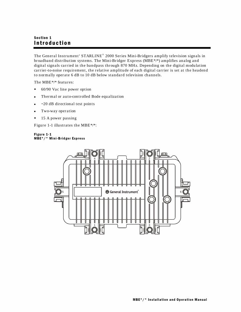
The General Instrument® STARLINE® 2000 Series Mini-Bridgers amplify television signals inbroadband distribution systems. The Mini-Bridger Express (MBE*/*) amplifies analog anddigital signals carried in the bandpass through 870 MHz. Depending on the digital modulationcarrier-to-noise requirement, the relative amplitude of each digital carrier is set at the headendto normally operate 6 dB to 10 dB below standard television channels.
The MBE*/* features:
� 60/90 Vac line power option
� Thermal or auto-controlled Bode equalization
� −20 dB directional test points
� Two-way operation
� 15 A power passing
Figure 1-1 illustrates the MBE*/*:
F igure 1 - 1
MBE*/* Min i -Br id ger Express
1
2
3
4
5 6

1111 ---- 2222 I n t r o d u c t i o n
MBE*/* Insta l la t ion and Operat ion Manual
Us ing Th i s Manua l
The following sections provide information and instructions to bench test, install, and operatethe MBE*/*:
Section 1 Introduction provides a product description, related documentation, the technical helpline, and repair/returninformation.
Section 2 Overview describes the MBE*/* and includes details on the various options and their functions.
Section 3 Pre-Installation Procedures provides information to select and install optional components. It also providesconfiguration and bench-test procedures that are recommended before installing the unit.
Section 4 Installation provides instruction for installing the MBE*/* and performing field alignment.
Appendix A Specifications lists the applicable technical specifications for the MBE*/* and options.
Abbreviationsand Acronyms
The Abbreviations and Acronyms list contains the full spelling of the short forms used in this manual.
This manual uses standard NTSC analog channel information. Refer to catalog specifications forfurther details pertaining to signal levels of digital channels above 550 MHz.
This manual also uses 870 MHz as the reference frequency for cable loss and other valuesunless another frequency is given.
Re la ted Documenta t i on
This installation manual is complete and you should not require any additional documentationto install, test, or operate the MBE*/*.
Although not required, the Return Path Level Selection, Setup, and Alignment ProcedureReference Guide provides information that you can use when setting up the MBE*/*.
Document Con ven t i ons
Before you begin using the MBE*/*, familiarize yourself with the stylistic conventions used inthis manual:
SMALL CAPS Denotes silk screening on the equipment, typically representing front- and rear-panel controls, input/output (I/O)connections, and LEDs
* (asterisk) Indicates that several versions of the same model number exist and the information applies to all models; when theinformation applies to a specific model, the complete model number is given
Italic type Used for emphasis
I f You Need He lp
If you need assistance while working with the MBE*/*, call the General InstrumentTechnical Response Center (TRC) at 1-888-944-HELP (1-888-944-4357). The TRC is open from8:00 AM to 7:00 PM Eastern Time, Monday through Friday. When the TRC is closed, emergencyservice only is available on a call-back basis.
When contacting the TRC from outside the United States, call the main switchboard number,1-215-323-1000, and ask for extension 4200.

I n t r o d u c t i o n 1111 ---- 3333
MBE*/* Insta l la t ion and Operat ion Manual
Ca l l i ng f o r Repa i r s
If repair is necessary, call the General Instrument Repair Facility at 1-800-642-0442 for aReturn for Service Authorization (RSA) number before sending the unit. The RSA number mustbe prominently displayed on all equipment cartons. The Repair Facility is open from 7:00 AM to4:00 PM Pacific Time, Monday through Friday.
When calling from outside the United States, use the appropriate international access code andthen call 526-314-1000, extension 3194, to contact the Repair Facility.
When shipping equipment for repair, follow these steps:
1 Pack the unit securely.
2 Enclose a note describing the exact problem.
3 Enclose a copy of the invoice that verifies the warranty status.
4 Ship the unit PREPAID to the following address:General Instrument Corporationc/o William F. Joffroy, Inc.Attn: RSA #___________1480 North Industrial Park Dr.Nogales, AZ 85621

MBE*/* Insta l la t ion and Operat ion Manual
Sect ion 2
Ove r v i ew
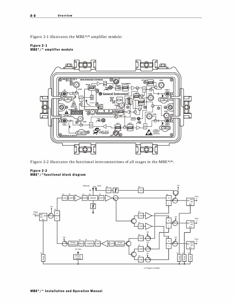
The MBE*/* is a three output amplifier with one output port dedicated to trunk levelperformance and two output ports for distribution levels. For improved performance, the trunkport uses two hybrid amplifiers to enable cascades of greater length. The distribution portsemploy high-gain, three-stage hybrid amplifiers to drive both a limited cascade and a localdistribution system. The amplifier provides up to 132 channel capability using silicon andgallium arsenide (GaAs) technology. The S-split version of the MBE*/* uses a forward bandpassfrom 52 through 870 MHz and a return path from 5 through 40 MHz (65/85, 42/54, 30/47, and55/70 MHz diplex filter splits are also available). The high-gain feature — 37 dB distributionand 28 dB operational trunk — makes the amplifier suitable for drop-in replacement of trunkamplifiers that were originally spaced for 22 dB at 550 MHz. The expanded reach of the MBE*/*enables you to cascade several of its trunk-level outputs. This feature is beneficial in rural areaswhere you can maintain the total number of subscribers, per fiber-optic node, at a target level.
The attenuation of coaxial cable, as used in Community Antenna Television (CATV) systems,changes with variations in temperature. The interstage Bode board is an electrically controlledequalizer. It receives its control input from either the Automatic Drive Unit (ADU) or theThermal Drive Unit (TDU) control boards. The Bode board compensates for coaxial cableattenuation changes caused by temperature variations. It also compensates for hybrid changesover the entire temperature range. If necessary, you can control the Bode board manually with apotentiometer, however, we do not recommend permanent operation of the MBE*/* in manualmode. The MBE*/* maintains its distortion performance over wide temperature ranges usingthe Bode equalizer and hybrid thermal-compensation network with ADU control.
The standard MBE*/* is shipped in housing model MB-HSG and includes all necessarycomponents for a fully functional one-way amplifier. The forward cable equalizer, model EQ-*-*,is not included.
2222 ---- 2222 O v e r v i e w
MBE*/* Insta l la t ion and Operat ion Manual
Figure 2-1 illustrates the MBE*/* amplifier module:
F igure 2 - 1
MBE*/* ampl i f i e r module
20
20
20
20
ASSEMBLED IN MEXICO
POWER
MBE
A
J
S G87
75
E
K
REFER TO
MANUAL FOR
FUSE VALUES
CHECK VOLTAGE
SELECTOR
REFER TO MANUAL
L
-20dB
-20dB
JXP 4
JXP 2
JXP 3
ADU
-20dB
-20dB
-20dB
-20dB
JXP INJXP COMMON
JXP ADU -20dB
JXP 4 JXP 3
-20dB
JXP
MAN
TDU
ADU
IN
PORT 3
PORT 2
PORT 4
L
H
L
H
L
H
MAN
DRIVE
UNIT
BODE
MDR
JXP
THERM
MINI-BRIDGER EXPRESS
RTN
EQ
H
CAUTION:CONTAINS PARTSAND ASSEMBLIESSUSCEPTIBLE TO
DAMAGE BYELECTROSTATIC
DISCHARGE (ESD)
dB
FWD
EQ
Figure 2-2 illustrates the functional interconnections of all stages in the MBE*/*:
F igure 2 - 2
MBE*/*funct iona l b lock d iagram
TP
TP
TP
Inputport 1
Port2
Port3
Port4
RF/AC
RF/AC
RF
RF
AC
ACTP
TP
TP
H
L
**
**
H
H
L
L
**
**
**JXP
TP
TP
**
**
JXP
JXP
**JXP
**
**
JXP
JXP
H
** **
** **
**SEE JXP LPF
Surgeprotector
SurgeprotectorTHERM
L
**
Fus
e
**
**
Fus
e
Fus
e
Fus
ePowersupply
Plug-in module
24 Vdc
Manual Auto
** ** ** **
**
**EQ JXP JXP
ADU
EDR BODE
RF/ACRF
AC
RF/ACRF
AC

O v e r v i e w 2222 ---- 3333
MBE*/* Insta l la t ion and Operat ion Manual
Assemb l i e s and Modu l es
The following subsections describe each of the major components and subassemblies associatedwith the MBE*/*:
Housing
The housing protects the electronics from the elements and serves as a radiator to dissipateinternally generated heat. The amplifiers are shipped with the model MB-HSG housing.
Coaxial cable connections to the housing are made using conventional 5/8 inch × 24 threads perinch stinger-type connectors. The included clamp and bolt assemblies enable strand mounting ofthe housing. Surface mounting requires suitable auxiliary brackets. For pedestal or surfacemounting, use the two 1/4 × 20 threaded holes cast in the lower housing.
A combination woven-wire/silicone-rubber gasket between the body and the cover providesefficient ground continuity, RF shielding, and weather protection for all housings.Factory-inserted, plastic cap plugs protect the input and output ports. Discard these plugs afteryou install the cable connectors.
Figure 2-3 illustrates a top view and the dimensions of the MB-HSG housing:
F igure 2 - 3
MB-HSG hous ing and d imens ions( top)
1
2
3
4
5 6 9.6
15.4

2222 ---- 4444 O v e r v i e w
MBE*/* Insta l la t ion and Operat ion Manual
Figure 2-4 illustrates a side view and the dimensions of the MB-HSG housing:
F igure 2 - 4
MB-HSG hous ing and d imens ions (s ide v iew)
5.6
Power Control Options
The distribution amplifier uses fuses to direct and limit power from the input port to the feederport. The maximum permissible ac current through any port is 15 A. 20 A fuses are in serieswith the input and outputs to protect the amplifier from overcurrent. These fuses also serve theadditional function of a switch. You can eliminate power by pulling the appropriate fuse.
The model MPPS-II 60/90 power pack includes a heavy-duty gas discharge tube that you canreplace with the optional fast-trigger electronic crowbar (FTEC) surge protector. The FTECcrowbar circuit fires at approximately 230 V and presents a short circuit to the line duringperiods of overvoltage. After the ac input voltage returns to normal, the FTEC resumes its openstate. Figure 2-7 illustrates the MPPS-II power pack and the location of the optionalcomponents.
The cover of the amplifier houses the model MPPS-II 60/90 power pack. It provides a regulated24 Vdc output at 2.5 A maximum over an ac input voltage range from 38 Vac through90 Vac rms. The MPPS-II has an extended voltage range. The supply continues to deliverregulated power to the load up to 200 Vac however, the power factor will degrade.
The input-voltage waveshape is either a quasi-squarewave or a sinewave. The surge protectorand the electromagnetic interference (EMI) filter protect the power pack and amplifier fromtransient spikes. An integral fast-acting zener diode provides additional surge protection. A 5 Afuse in the ac line offers further protection in case of catastrophic power pack failure. Thepreregulator is a fixed frequency switching regulator that presents a near perfect power factorto the input line and provides overvoltage and overcurrent protection. A precision outputregulator provides a precise output voltage and is also protected against overcurrent and shortcircuits. If a short circuit is detected, the power supply shuts down and the regulator initiates asequence of line test pulses at approximately one-half second intervals. The regulator continuesthese pulses for the duration of the short circuit but returns to normal operation when the faultis cleared.

O v e r v i e w 2222 ---- 5555
MBE*/* Insta l la t ion and Operat ion Manual
Figure 2-5 illustrates a block diagram of the MPPS-II power pack:
F igure 2 - 5
MPPS- I I p ower pack b l ock d ia gram
EMI Filter
Overvoltageand
power-factorcorrection
60/90Vac
24Vdc
Preregulator Isolationtransformer
Bridgerectifier
Precisionregulator
Figure 2-6 illustrates the MPPS-II power pack installed in the upper half of theMB-HSG-housing:
F igure 2 - 6
MPPS- I I p ower pack
HI
LO
FTEC
NO USER SERVICABLEPARTS INSIDE
USE CAUTIONWHENMAKINGINTERNALADJUSTMENTSWITHCOVERREMOVED
SEE INSTALLATION MANUALFOR SERVICE
CAUTIONVOLTAGES INEXCESS OF300 VOLTS ARE PRESENTUNDER COVER AND MAY
BE PRESENTFORSEVERALMINUTES AFTER POWER
IS REMOVED
AC TEST POINT
24V TEST POINT
MPPS-II

� � � 2 Y H U Y L H Z
0%( � � ,QVWD O OD W LRQ �DQG �2SHUDW LRQ �0DQXDO
In the MBE*/* an internal voltage selector (J1) enables operation over an input voltage rangefrom 38 Vac through 60 Vac (LO) or from 55 Vac through 90 Vac (HI). Units are shipped with theselector set for 60 Vac (LO). Section 3, “Pre-installation Procedures,” explains changing thesetting of this selector to meet system requirements. You must remove the power-pack cover toaccess the selector illustrated in Figure 2-7:
) LJXUH �� � �9R O WDJH � UDQJH �VH O HFWRU � ORFDW LRQ
LO
HIJ1
Surgeprotector
Voltageselector
)RUZDUG�$PSOL ILHU
The forward amplifier’s electronics consist of a single two-stage trunk path and two parallelthree-stage distribution paths. The first two stages are common to all three paths. Thepre-amplifier stage provides a low noise figure, while the output stage contributes the desiredpower at low distortion. The amplifier input provides a facility to install a cable equalizer and asocket for a model JXP-*A attenuator. Both the attenuator and equalizer are customer-installedoptions.
Several circuits comprise the intermediate amplifier stages. The Bode equalizer is avoltage-controlled device that, in the standard configuration form, receives its input from themanual gain control. It also receives its input from the ADU-* or TDU-* board when either ofthese options is employed. A flatness-control circuit precedes the Bode board and enablesoptimization of the frequency response. The standard *EDR/*/* board serves two functions: itcontrols flatness and provides equalization producing 12.5 dB of tilt for the amplifier output.This tilt is equivalent to approximately 16 dB of PIII 0.75-inch cable at 870 MHz. Following theBode board, a JXP facility adjusts the RF level into the interstage hybrid amplifier.

O v e r v i e w 2222 ---- 7777
MBE*/* Insta l la t ion and Operat ion Manual
Figure 2-8 illustrates the location of the major components on the amplifier module:
F igure 2 - 8
Forward ampl i f ie r module -major components
AUTOMATICDRIVE UNIT
ADU/ _______________499.25
20
20
20
20
*EDR/*/*
EQ/BCSBODE
equalizer
ADU-*
Accurate 20-dB directional-coupler test points are available at the input and at the output of theamplifier. Because these test points are 75-ohm source impedance, they do not require specialtest probes.
After the interstage hybrid amplifier, a directional coupler on the trunk path provides a signalfor the distribution paths. A second directional coupler provides a signal to the optional ADUboard. This signal is used only with the ADU board; you do not need to terminate this port whenthe ADU is not installed.
The distribution path passes through a two-way splitter. Each output then provides signal todrive the output hybrid amplifiers. You can place appropriate value pads between the splitteroutput legs and the hybrids to balance the signal level.

2222 ---- 8888 O v e r v i e w
MBE*/* Insta l la t ion and Operat ion Manual
Return Ampli fier, RA-K it/H or RA-Ki t/L
The circuit board of the forward amplifier accommodates the optional return amplifier.Installing the return amplifier kit RA-Kit/H or RA-Kit/L equips the MBE*/* amplifier to passsignals in the return or upstream direction. The return amplifier kit includes a return-amplifierhybrid and jumpers. Optional SEE-/* return equalizers compensate for cable attenuation andare available in 2 dB increments from 0 dB through 12 dB. S-split SEE-/* return equalizers areavailable in 1 dB increments.
The main amplifier board contains all components, including the diplex filters with extendedreturn bandwidth, for the amplifier input and output. All items are plug-in and easily installed.The output of the return amplifier includes two JXP-*A pad facilities. Selection of theoutput-pad value normally controls the return-signal level into the next upstream amplifier. AJXP-*A pad facility is included in each return input leg. Select an appropriate input pad toattenuate excessive input signal. You can also use either pad socket as a test point or a signalinjection point using the F/JXP-20 directional coupler.
Fo rwa rd Ou t pu t Le v e l Con t ro l
Use the drive-unit select jumper to manually or automatically control the forward output leveland gain. The gain potentiometer controls the gain of the amplifier when the drive-control selectjumper is in the manual position. Figure 2-1 illustrates the location of this jumper. If theamplifier cover is in place, the access hole to the gain potentiometer is labeled MAN. Use the MAN
position in underground cable installations that do not require thermal compensation. However,ADU control may be preferred in cascaded trunk applications. Generally, cable attenuation inunderground installations is constant. When the associated amplifier is located in a pedestalabove ground compensation is not essential. Refer to Section 4, “Installation,” Manual GainControl for the set-up procedure.
The STARLINE 2000 Series MBE*/* uses a Bode design that compensates for temperature-induced hybrid gain changes and coaxial cable changes. In buried plant installations, thethermal-compensation attenuator compensates for hybrid gain changes with temperature.
Amp l i f i e r Le ve l C on t ro l
In a cable system, signal levels vary with temperature primarily because cable attenuationchanges with temperature. Other components, such as passives and amplifier hybrids, are alsoaffected. One of the following options is selected to automatically compensate for these signalfluctuations:
� The ADU board, an optional plug-in module, monitors the amplitude of the selected pilotfrequency. The pilot frequency is an available television channel not scrambled by syncsuppression. Any changes in amplitude are fed back to the Bode equalizer, which makesappropriate corrections.

O v e r v i e w 2222 ---- 9999
MBE*/* Insta l la t ion and Operat ion Manual
� Although less accurate than the ADU, the optional TDU board compensates for signal-levelchanges by sensing housing temperature and signaling needed changes to the Bodeequalizer. Place the jumper on the TDU to the 10 dB, 20 dB, or 30 dB position. Choose thesetting that best represents the aerial cable loss at the highest frequency preceding theamplifier station.
Select manual control of the Bode board if the ADU or TDU board fails. Figure 2-1 illustratesthe location of the MAN potentiometer on the main circuit board. Because signals vary anddistortion performance changes, we do not recommend manual gain control during normaloperation.
Opt i ons and Accesso r i e s
The amplifier is shipped without an input forward equalizer or return equalizer. Whenconfigured appropriately for the field location requirements the wire jumpers must be removedfor proper operation. You must also install the correct equalizer or broadband cable simulator toplace the unit into service.
Use model JXP-* pads to control field signal levels. To compensate for temperature, install themodel ADU or TDU. These items are necessary for proper operation. Install other items such asa return amplifier and additional surge protection at your discretion; these options do notrender the unit inoperative if they are not included.
Table 2-1 provides a comprehensive list of optional equipment that works in conjunction withthe MBE*/*. To assist you in the selection process, the table also provides a brief description andbasic function of each item. Section 3, “Pre-Installation Procedures,” provides information tohelp you select the correct equalizer or cable simulator. Select the equipment that satisfiesindividual system requirements. Qualified technicians can install all optional equipment at fieldlocations.
Tab le 2 - 1
Opt ions and accessor ies fo r the MBE*/*
Model Descr ipt ion Funct ion
ADU-* Automatic control board This board provides automatic output-level control and requires theselection of a pilot frequency. Install either an ADU or TDU in the unit.
TDU Thermal control board This board controls amplifier gain and slope by compensating fortemparature-induced changes in cable attenuation. Install either an ADU orTDU in the unit.
RA-Kit/H or L Return amplifier kit This kit enables two-way operation and includes a return hybrid andjumpers. The RA-Kit/H hybrid has 30 dB of gain while the RA-Kit/L hybridhas 24 dB of gain.
EQ-75-*
EQ-87-*
Cable equalizers These equalizers compensate for cable attenuation in 1 dB incrementsfrom 2 through 22 dB. See the product catalog for additional informationand install the appropriate value.
BCS-* Broadband cable simulator This option simulates the property of cable when insufficient cable exists.
JXP-*A Fixed attenuator This pad attenuates excessive input signal in ½ dB increments from 1 dBthrough 22 dB. Install the appropriate value.

2222 ---- 1 0101010 O v e r v i e w
MBE*/* Insta l la t ion and Operat ion Manual
Model Descr ipt ion Funct ion
FTEC Crowbar overvoltage protection Use this option to replace the existing surge protector.
SEE-*-* Return equalizer This option compensates for cable attenuation in 2 dB increments (1 dBfor S-split) from 0 dB through 12 dB. See the product catalog for additionalinformation and install the appropriate value.
JXP-TH2 orJXP-TH3
Thermal attenuators This option compensates for gain changes with temperature in the returnpath.
BAF-* Feeder line fuse This automotive-type fuse powers the output port and provides protectionagainst overcurrent.
F/JXP-20 20-dB directional coupler Use this test adapter to inject signal or measure level at any JXP location.
663-008-000 Heat sink compound This compound helps dissipate equipment heat.
Figure 2-9 illustrates the location of options and accessories in the MBE*/*:
F igure 2 - 9
MBE*/* ampl i f i e r module -opt ions and accessor ies
AUTOMATICDRIVE UNIT
ADU/ _______________499.25
20
20
20
20
EQ/BCS
ADU-*SEE-*-* Returnhybrid
*EDR/*/*BODE
equalizer
or TDU

0%( � � ,QVWD O OD W LRQ �DQG �2SHUDW LRQ �0DQXDO
6HFW LRQ ��
3 UH � , Q V W D O O D W L R Q � 3 U RFHGX U H V
Before you begin, you must obtain system records that include signal levels, equalizer values,initial pad values, and fuse or circuit breaker details. It is helpful to have a cable simulator thatyou can construct by cutting and measuring various lengths of cable, that when interconnected,add up to the desired cable value.
Add the components required by your system-layout documentation. Configure the unit andperform bench testing before installing the MBE*/*. If you have access to a network analyzer,use it in place of a bench sweep system. The pre-installation procedure ensures properalignment of all components and simplifies field installation and balancing.
&RQ I L JX U L Q J � W KH �0%( �
Before you install the unit, configure the amplifier to suit your system requirements.Configuration includes selecting and installing the components that are described in thefollowing subsections. Major components include:
� Cable equalizer, model EQ-*-*, or broadband cable simulator, model BCS-*
� Powering and surge protection options
� Control board option, model ADU-* or TDU
� Two-way option return amplifier model RA-Kit/H or RA-Kit/L and return equalizer modelSEE-*-*
The MBE*/* is shipped with 20 A blade-type fuses for over-current protection. You must removethese fuses to avoid applying 60/90 Vac to the test equipment during testing.
Before you install the selected options, unplug the power cord from the amplifier module. Pressthe locking tab of the connector and pull until it releases. Loosen the screws holding the cover inplace and remove the cover. Component locations are now accessible.
&DEOH�(TXDOL]HU
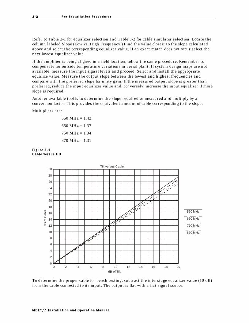
The MB*/* is factory configured with an interstage *EDR/*/* board installed. The standardversion (Model *EDR/8/12) compensates for 16 dB of cable at the highest frequency. Foroptimum performance with a flat input slope, the *EDR/*/* should provide the total amount ofoutput slope required between the lowest and highest frequencies in the forward path. Aforward equalizer or cable simulator is required for additional compensation as the result ofcable and passive losses prior to the input of the amplifier. Equalizers are available in 1 dBincrements from 2 dB through 22 dB.
To select the proper forward input equalizer for bench alignment prior to field installation, referto system design maps. Determine the calculated input signal levels to the MBE*/*. Subtractthe lowest from the highest frequency inputs. If the resulting number is positive a cableequalizer is required to reduce the signal levels into the amplifier at the lower frequencies.Conversely, a negative number indicates the selection of a cable simulator, usually occurringwhen small amounts of cable occur between amplifiers.
3333 ---- 2222 P r e - I n s t a l l a t i o n P r o c e d u r e s
MBE*/* Insta l la t ion and Operat ion Manual
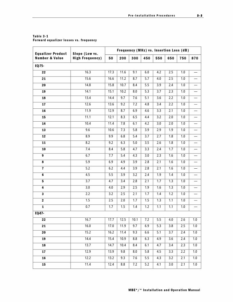
Refer to Table 3-1 for equalizer selection and Table 3-2 for cable simulator selection. Locate thecolumn labeled Slope (Low vs. High Frequency.) Find the value closest to the slope calculatedabove and select the corresponding equalizer value. If an exact match does not occur select thenext lowest equalizer value.
If the amplifier is being aligned in a field location, follow the same procedure. Remember tocompensate for outside temperature variations in aerial plant. If system design maps are notavailable, measure the input signal levels and proceed. Select and install the appropriateequalize value. Measure the output slope between the lowest and highest frequencies andcompare with the preferred slope for unity gain. If the measured output slope is greater thanpreferred, reduce the input equalizer value and, conversely, increase the input equalizer if moreslope is required.
Another available tool is to determine the slope required or measured and multiply by aconversion factor. This provides the equivalent amount of cable corresponding to the slope.
Multipliers are:
550 MHz = 1.43
650 MHz = 1.37
750 MHz = 1.34
870 MHz = 1.31
F igure 3 - 1
Cable versus t i l t
dBof
Cab
le
dB of Tilt
00
2 4 6 8 10 12 14 16 18 20
30
28
26
24
22
20
18
16
14
12
10
6
4
2
8
550 MHz
650 MHz
750 MHz
870 MHz
Tilt versus Cable
To determine the proper cable for bench testing, subtract the interstage equalizer value (10 dB)from the cable connected to its input. The output is flat with a flat signal source.
P r e - I n s t a l l a t i o n P r o c e d u r e s 3333 ---- 3333
MBE*/* Insta l la t ion and Operat ion Manual
Tab le 3 - 1
Forward equa l i zer l osses vs . frequency
Frequency (MHz) v s . Insert i on Loss (dB)Equal izer Product
Number & Value
Slope (Low vs.
High Frequency) 50 200 300 450 550 650 750 870
EQ-75-
22 16.3 17.3 11.6 9.1 6.0 4.2 2.5 1.0 —
21 15.6 16.6 11.2 8.7 5.7 4.0 2.5 1.0 —
20 14.8 15.8 10.7 8.4 5.5 3.9 2.4 1.0 —
19 14.1 15.1 10.2 8.0 5.3 3.7 2.3 1.0 —
18 13.4 14.4 9.7 7.6 5.1 3.6 2.2 1.0 —
17 12.6 13.6 9.2 7.2 4.8 3.4 2.2 1.0 —
16 11.9 12.9 8.7 6.9 4.6 3.3 2.1 1.0 —
15 11.1 12.1 8.3 6.5 4.4 3.2 2.0 1.0 —
14 10.4 11.4 7.8 6.1 4.2 3.0 2.0 1.0 —
13 9.6 10.6 7.3 5.8 3.9 2.9 1.9 1.0 —
12 8.9 9.9 6.8 5.4 3.7 2.7 1.8 1.0 —
11 8.2 9.2 6.3 5.0 3.5 2.6 1.8 1.0 —
10 7.4 8.4 5.8 4.7 3.3 2.4 1.7 1.0 —
9 6.7 7.7 5.4 4.3 3.0 2.3 1.6 1.0 —
8 5.9 6.9 4.9 3.9 2.8 2.1 1.6 1.0 —
7 5.2 6.2 4.4 3.9 2.8 2.1 1.6 1.0 —
6 4.5 5.5 3.9 3.2 2.4 1.9 1.4 1.0 —
5 3.7 4.7 3.4 2.8 2.1 1.7 1.3 1.0 —
4 3.0 4.0 2.9 2.5 1.9 1.6 1.3 1.0 —
3 2.2 3.2 2.5 2.1 1.7 1.4 1.2 1.0 —
2 1.5 2.5 2.0 1.7 1.5 1.3 1.1 1.0 —
1 0.7 1.7 1.5 1.4 1.2 1.1 1.1 1.0 —
EQ-87-
22 16.7 17.7 12.5 10.1 7.2 5.5 4.0 2.6 1.0
21 16.0 17.0 11.9 9.7 6.9 5.3 3.8 2.5 1.0
20 15.2 16.2 11.4 9.3 6.6 5.1 3.7 2.4 1.0
19 14.4 15.4 10.9 8.8 6.3 4.9 3.6 2.4 1.0
18 13.7 14.7 10.4 8.4 6.1 4.7 3.4 2.3 1.0
17 12.9 13.9 9.8 8.0 5.8 4.5 3.3 2.2 1.0
16 12.2 13.2 9.3 7.6 5.5 4.3 3.2 2.1 1.0
15 11.4 12.4 8.8 7.2 5.2 4.1 3.0 2.1 1.0

3333 ---- 4444 P r e - I n s t a l l a t i o n P r o c e d u r e s
MBE*/* Insta l la t ion and Operat ion Manual
Frequency (MHz) v s . Insert i on Loss (dB)Equal izer Product
Number & Value
Slope (Low vs.
High Frequency) 50 200 300 450 550 650 750 870
14 10.6 11.6 8.3 6.8 4.9 3.9 2.9 2.0 1.0
13 9.9 10.9 7.8 6.4 4.7 3.7 2.8 1.9 1.0
12 9.1 10.1 7.2 6.0 4.4 3.5 2.6 1.9 1.0
11 8.4 9.4 6.7 5.5 4.1 3.3 2.5 1.8 1.0
10 7.6 8.6 6.2 5.1 3.8 3.0 2.4 1.7 1.0
9 6.8 7.8 5.7 4.7 3.5 2.8 2.2 1.6 1.0
8 6.1 7.1 5.2 4.3 3.2 2.6 2.1 1.6 1.0
7 5.3 6.3 4.6 3.9 3.0 2.4 1.9 1.5 1.0
6 4.6 5.6 4.1 3.5 2.7 2.2 1.8 1.4 1.0
5 3.8 4.8 3.6 3.1 2.4 2.0 1.7 1.4 1.0
4 3.0 4.0 3.1 2.7 2.1 1.8 1.5 1.3 1.0
3 2.3 3.3 2.6 2.2 1.8 1.6 1.4 1.2 1.0
2 1.5 2.5 2.0 1.8 1.6 1.4 1.3 1.1 1.0
1 0.8 1.8 1.5 1.4 1.3 1.2 1.1 1.1 1.0
Table 3-2 and Figure 3-2 help you choose the correct simulator:
Tab le 3 - 2
Broadband cab le s imulator va lues
Slope Frequency (MHZ) vs . Insert ion Loss (dB)
Cable
simulator
BCS value
50
vs.
550
50
vs.
750
50
vs.
870 50 200 300 450 550 650 750 870
1 −0.8 −1.0 −1.1 −1.0 −1.3 −1.5 −1.7 −1.8 −1.9 −2.0 −2.1
2 −1.6 −2.0 −2.3 −1.0 −1.7 −2.0 −2.4 −2.6 −2.8 −3.0 −3.3
3 −2.3 −3.0 −3.3 −1.0 −1.9 −2.4 −3.0 −3.3 −3.7 −4.0 −4.3
4 −3.1 −4.0 −4.4 −1.0 −2.3 −2.9 −3.7 −4.1 −4.6 −5.0 −5.4
5 −3.9 −5.0 −5.5 −1.0 −2.6 −3.4 −4.4 −4.9 −5.5 −6.0 −6.5
6 −4.8 −6.0 −6.7 −1.0 −3.0 −3.9 −5.1 −5.8 −6.4 −7.0 −7.7
7 −5.6 −5.6 −7.8 −1.0 −3.3 −4.4 −5.8 −6.6 −7.3 −8.0 −8.8
8 −6.4 −8.0 −8.9 −1.0 −3.7 −4.9 −6.5 −7.4 −8.3 −9.0 −9.9
9 −7.1 −9.0 −9.9 −1.0 −3.9 −5.3 −7.0 −8.1 −9.1 −10.0 −10.9
10 −7.9 −10.0 −11.1 −1.0 −4.3 −5.8 −7.7 −8.9 −10.0 −11.0 −12.1

3 U H � , Q V W D O O D W L R Q � 3 U R F H G X U H V � � �
0%( � � ,QVWD O OD W LRQ �DQG �2SHUDW LRQ �0DQXDO
Figure 3-2 illustrates the information presented in Table 3-2 in graph form:
) LJXUH �� � �)UHTXHQF\ � YHUVXV �FDE OH �V ORSH
0
-1
-2
-3
-4
-5
-6
-7
-8
-9
-10
-11
-12
40 100
150
200
250
300
350
400
450
500
550
600
650
700
750
800
870
BC
S-*
inse
rtio
n lo
ss (
dB)
Frequency (MHz)
1
BCS
10
2
3
4
5
6
7
8
9
The following two examples present several alternatives:
([DPSOH ��
The amplifier location includes 20 dB of cable (at 870 MHz) between its input and the precedingamplifier. Consider cable loss only. Exclude any flat loss due to splitters or other passivedevices. The internal equalizer, Model *EDR/8/12, compensates for 16 dB of cable. Subtract thiscable length from the 20 dB of this example (20 −16 = 4). The EQ-860-6 is the proper equalizerin this case. With this equalizer installed, the amplifier reproduces the output tilt of the lastupstream amplifier.
([DPSOH ��
The MBE*/* is used in a link following a fiber node. The fiber receiver output is flat andconnects to the input of the amplifier through 18 dB of cable plus passive loss. Determine whichis the proper equalizer to achieve the 12.5 dB output tilt from the amplifier.
Calculate the equalizer value using:
SLOPEeq = TILTout + SIGlo − SIGhi − SLOPEieq
where:
SLOPEeq = required EQ-87-* slope
TILTout = required amplifier output tilt
SIGlo = signal input level at 54 MHz (channel 2)
SIGhi = signal input level at 870 MHz
SLOPEieq = interstage equalizer slope (12.5 dB)
3333 ---- 6666 P r e - I n s t a l l a t i o n P r o c e d u r e s
MBE*/* Insta l la t ion and Operat ion Manual
At an operating frequency of 870 MHz, 18 dB of cable produces approximately 3.9 dB of loss at54 MHz. This suggests that the channel 2 signal input to the MBE*/* is 14.1 dB greater(18 − 3.9 = 14.1) at channel 2 than at 870 MHz. Our example assumes that the high-endfrequency level into the amplifier is +12 dBmV.
Substituting this information into the above equation gives:
11 dB + 26.1 dB − 12-dBmV − 12.5 dB = 12.6 dB
The slope of the required equalizer is 12.6 dB. Translate this to an equivalent cable value byconsulting Figure 3-1 or using the appropriate multiplier. The multiplier in this case is 1.28 dB(12.6 × 1.28 = 16.13). Therefore, the correct equalizer is the EQ-87-16, the closest availableequalizer value.
Multipliers to convert tilt to cable equivalent are:
550 MHz = 1.46
650 MHz = 1.40
750 MHz = 1.37
870 MHz = 1.28
Because of errors in cable attenuation, slope in passive devices, and other independentvariables, you may need to change the final value of the equalizer before installing the unit.
Input and Midstage Pads
Install model JXP-*A pads to attenuate the signal per system design drawings. Generally, thisconsists of attenuating excessive input levels. Select and install the specified pad in the socketlabeled JXP-FWD IN. The midstage pad normally remains at 0 dB. System performancecalculations should be thoroughly reviewed before changing this pad value.

P r e - I n s t a l l a t i o n P r o c e d u r e s 3333 ---- 7777
MBE*/* Insta l la t ion and Operat ion Manual
Powering and Surge Protection Options
In conventional applications the MBE*/* is powered through the input port. A 20 A, blade-typefuse is furnished in the amplifier module and provides overcurrent protection for ac powerapplied to the input. You can power the MBE*/* from the output without passing power throughto the input port. To block power from the input port remove the fuse.
WARNING!
To avoid possible injury to personnel or damage to the equipment, remove 60/90 V ac power from
the system before you remove any components from the housing.
The supplied MPPS-II 60/90 power pack has two voltage ranges: 38 Vac through 60 Vac (LO) and55 Vac through 90 Vac (HI). Figure 3-3 illustrates the power pack and the location of the 60/90 Vrange selector, three vertical board-mounted pins, and suitcase jumper:
F igure 3 - 3
Locat ion o f vo l ta ge se l ector
LO
HIJ1
Surgeprotector
Voltageselector
The MBE*/* is shipped from the factory configured for 38 Vac through 60 Vac powering.
To configure the mini-bridger for 55 Vac through 90 Vac operation:
1 Remove the power-supply cover.
2 Move jumper J1 on the power-supply board from the LO to HI position. Figure 3-3 illustratesthe jumper location.
3 Re-install the power-supply cover.
The MPPS-II power pack is furnished with a heavy-duty, 230-V, gas discharge surge protector.In some cases, the preferred method of surge protection is the model FTEC. The FTEC has afiring potential of approximately 230 V. You can install this electronic option in the MPPS-IIpower pack as a replacement for the surge protector.

3333 ---- 8888 P r e - I n s t a l l a t i o n P r o c e d u r e s
MBE*/* Insta l la t ion and Operat ion Manual
To install the FTEC:
1 Remove the power supply cover.
2 Remove the gas-tube surge protector illustrated in Figure 3-3.
3 Replace it with the FTEC.
4 Re-install the power supply cover.
ADU/TDU Drive Uni ts
There are three methods to control the amplifier output level: ADU, TDU, or manual gain.
The ADU operates by monitoring the amplitude of a chosen, clear, pilot channel. Changes insignal level are fed back to the Bode board. Typically, the encountered signal-level change is theresult of changing temperature and the subsequent change in cable attenuation. The Bodeboard responds by changing its insertion loss to maintain a constant output level. This modulemaintains the most precise output level of the three available methods. For automaticoutput-level control by the ADU, the jumper must be in the DRIVE UNIT position.
The TDU senses temperature and controls the Bode board. Typically, the cable is subjected tothe same or similar temperature as the Bode board. The TDU then compensates for the amountof cable chosen with the selector on the TDU circuit board: 10, 20, or 30 dB. Place thedrive-unit-select jumper in the DRIVE UNIT position for automatic output-level control by theTDU. Figure 2-1 illustrates the module cover and the location of the TDU.
Figure 3-4 illustrates the TDU cable selector:
F igure 3 - 4
TDU cab le se lector
10 dB
20 dB
30 dB
The single control (potentiometer) on the TDU controls gain. Use this control to adjust the Bodeequalizer.
To adjust the TDU:
1 Apply power to the unit and check the power-supply output. The voltage at thepower-supply test point must be +24 Vdc ± 0.2 V.
2 Connect a signal level meter to the output test point. Use the manual level control to reducethe level of the highest frequency channel by the required gain reserve.
When you install an ADU or TDU, line up the pins carefully before you press the unit into place.Excessive force is not required and can result in bent pins.

P r e - I n s t a l l a t i o n P r o c e d u r e s 3333 ---- 9999
MBE*/* Insta l la t ion and Operat ion Manual
You can operate the MBE*/* in the manual mode if the ADU-* or TDU fails. Select manualmode by placing the gain-select jumper, illustrated in Figure 2-1, in the MAN position. Thecontrol marked MAN on the cover now governs the output of the mini-bridger. GeneralInstrument recommends that you use the ADU-* or TDU for improved output-level stability. Donot use manual mode for extended periods.
Figure 3-5 illustrates the ADU-* circuit-board and ADU-* pad location in the amplifier:
F igure 3 - 5
ADU-* and ADU-* pad locat ion
7.5A
AUTOMATICDRIVE UNIT
ADU/ _______________499.25
20
20
20
20
EQ/BCS
BODEequalizerC108 ADU-* padC115
ADU-**EDR/*/*

3333 ---- 1 0101010 P r e - I n s t a l l a t i o n P r o c e d u r e s
MBE*/* Insta l la t ion and Operat ion Manual
To insert the board, carefully mate the pins on the ADU-* with the socket on the main circuitboard. The keyed-socket pins enable entry in one position only. To enable the ADU-*, place thedrive-unit select jumper in the DRIVE UNIT position. To disable automatic level control at anytime, place the drive-unit select jumper in the MAN position.
Figure 3-6 illustrates the drive unit selector:
F igure 3 - 6
Dr i ve un i t se lector
MAN
MAN
-20dB
DRIVEUNIT
The supplied ADU-* is tuned to the pilot-frequency channel. This non-sync suppressedmodulated or unmodulated channel must be present on the system continuously. It is notpractical to retune the ADU-* to an alternate frequency.
Flatness
Adjust the *EDR/*/* board and trimmer capacitors C115 and C108 on the main board to correctpeak-to-valley response variations. Figure 3-5 illustrates the location of these two capacitors.Replace the equalizer if the response exhibits tilt.
Figure 3-7 illustrates the location of the controls on the *EDR/*/* board:
F igure 3 - 7
*EDR/*EDR/*EDR/*EDR/*/* board
(C7) 52 MHz
(R2) 52-75 MHz
(C4) 750 MHz and up
(C1) 95-500 MHz
(C2) 52-110 MHz
(R3) 52-150 MHz
(C6) 52-450 MHz
(R5) 160-790 MHz
(C3) 52-170 MHz
(R4) 75-250 MHz

P r e - I n s t a l l a t i o n P r o c e d u r e s 3333 ---- 1 1111111
MBE*/* Insta l la t ion and Operat ion Manual
Figures 3-8 and 3-9 illustrate the approximate effects on the frequency response of theamplifier:
F igure 3 - 8
Ef fects o f f la tness cont ro ls on the *EDR/*/* b oard
CH 1 S21 /M log MAG 2 dB/ REF 41.34 dB
START 5.000 000 MHz STOP 870.000 000 MHz
C6 R5
C7 and R2 C1 C4
C3 and R4
C2 and R3
The changes in response, as they are shown, were obtained by comparison against a normalizedtrace to emphasize the effect of the various controls.

3333 ---- 1 2121212 P r e - I n s t a l l a t i o n P r o c e d u r e s
MBE*/* Insta l la t ion and Operat ion Manual
F igure 3 - 9
Ef fects o f f la tness cont ro ls on the main board
CH1 S21
S21
/M log MAG 2dB/ REF 41.35dB
Cor
CH 1 START 54.000 000 MHz STOP 870.000 000 MHz
C115
1
2
CH1 /M log MAG 2dB/ REF 41.35dB
Cor
CH 1 START 54.000 000 MHz STOP 870.000 000 MHz
C108
1 2

P r e - I n s t a l l a t i o n P r o c e d u r e s 3333 ---- 1 3131313
MBE*/* Insta l la t ion and Operat ion Manual
Return Path Configuration
To implement two-way service, install the return amplifier kit (model RA-Kit/*).
The return amplifier kit contains a hybrid gain block and a selection of jumpers. Install theseitems in the module locations illustrated in Figure 3-10. Remove power from the MBE*/* andinstall the hybrid gain block carefully to ensure that all pins are straight and aligned with theappropriate sockets on the circuit board. To facilitate thermal conductivity, use heat-sinkcompound between the hybrid flange and the housing. Because its use is optional, heat-sinkcompound is not furnished with the kit. Secure the hybrid gain block to the circuit board usingthe furnished screws.
To test and align the return system, use the directional coupler test points provided. Thesetest-point signal levels are 20 dB below the actual levels. See Figure 2-2 for test point locations.You can also use the optional F/JXP-20 that can be installed in any three-pin JXP pad facility totest and align the return system.
Refer to the product catalog for SEE-*-* specifications.
Figure 3-10 illustrates the return amplifier components:
F igure 3 - 10
Return ampl i f ie r components
AUTOMATICDRIVE UNIT
ADU/ _______________499.25
20
20
20
20
EQ/BCS
ADU-*SEE-*-* Returnhybrid
*EDR/*/*BODE
equalizer
or TDU

3333 ---- 1 4141414 P r e - I n s t a l l a t i o n P r o c e d u r e s
MBE*/* Insta l la t ion and Operat ion Manual
Sweep Response and Gain Testing
Figures 3-11 and 3-12 illustrate typical test equipment and the interconnections required forpre-installation testing and bench sweeping:
F igure 3 - 11
Typ ica l test equ ipment and connect ions
Sweepgenerator
Sweepcomparator
117Vac
Cablesimulator
Powercombiner
MBE*/*under test
ac powersupply
Detectorand
display1
2
3
4
5 6

P r e - I n s t a l l a t i o n P r o c e d u r e s 3333 ---- 1 5151515
MBE*/* Insta l la t ion and Operat ion Manual
F igure 3 - 12
Test equ ipment connect ions fo r bench sweep in g
60/90VacPowersupply
Unitunder test
Inputport1
Port2
Port 4Port 3
RF Out RF In
Pilotgenerator
(modulator) OscilloscopeSweep
generator
Signallevelmeter
Note:Terminate all unused outputs.
Dashed line represents alternateconnections for ADU-* testing.
V
HH
V
RFOut DET
Atten.no. 1
0.500"Cable
SSP-PIN
See text
Atten.no.2
Measuring Forward Gain
To measure the forward gain of the amplifier:
1 Determine whether the power-supply jumper (J1) is positioned for LO (60 Vac) or HI (90 Vac)operation. Connect the MBE to the test equipment and apply power. Verify that the B+voltage is 24 V ± 0.4 V. Apply the sweep signal and adjust the test equipment as needed.
2 To select manual gain, place the jumper in the proper position and turn the MANUAL LEVEL
control fully clockwise.
3 Measure the gain at a forward frequency using the procedure outlined in the operatormanual provided with the test equipment in use. To correct this number, add the insertionloss of the SSP-PIN power combiner (0.5 dB at 550 MHz, 0.6 dB at 750 MHz, or 0.7 dB at870 MHz), the loss of the cable simulator at the forward frequency, and the loss of the cableequalizer (1.0 dB) if it is installed.

3333 ---- 1 6161616 P r e - I n s t a l l a t i o n P r o c e d u r e s
MBE*/* Insta l la t ion and Operat ion Manual
Example
The test equipment indicates a measured gain of 12.5 dB with the MBE*/* and the cablesimulator set to 20 dB.
0.8 dB (power combiner)+ 1.0 dB (cable equalizer)
+ 20.0 dB (cable simulator)+ 12.5 dB (measured gain)
34.3 dB (unit gain)
The result must meet advertised specifications for the unit.
By setting the operational gain of the MBE*/* 4 dB below minimum full gain, the unit operatesin the proper region of the Bode board.
Testing Return Gain and Response
After you configure the return path you can test the return bandpass to ensure compliance withspecifications. The return amplifier is a flat amplifier; therefore, the cable simulator mustremain in the test set-up and set to the same cable equivalent as in the forward sweep test. Thisprovides an approximate indication of the frequency response that you can achieve in the field.
To test for return gain and response:
1 Reconnect the test equipment and switch the sweep input and sweep output leads of theMBE*/* under test. Re-adjust the test equipment to sweep from 4 MHz through 50 MHz.
2 The expected response is flat. Tilt that is due to the return equalizer must average out to aflat response in a cascade of amplifiers. A slope adjustment is not available in the returnbandpass.
3 Measure the gain at 40 MHz. The amplifier gain is the sum of: the measured gain, theinsertion loss of the return cable equalizer at 40 MHz, the insertion loss of the powercombiner, any pads installed in either the input or output pad locations, plus the cablesimulator loss at 40 MHz. The measured gain must meet advertised specifications for thereturn amplifier.
Example
14.0 dB (measured gain)
+ 1.0 dB (equalizer insertion loss)+ 0.8 dB (power combiner)+ 0.0 dB (pads)+ 4.6 dB (cable simulator at 40 MHz)20.4 dB (unit gain)
Completing the Test Procedures
The amplifier is now approximately tailored for a specific field location. Additional adjustmentsafter installation are minor in nature. Re-install the fuse, jumper, or circuit breaker removedduring testing.
To complete the station records, record pertinent information. Remove test-equipmentconnections and close the housing.

MBE*/* Insta l la t ion and Operat ion Manual
Sect ion 4
I n s t a l l a t i on
The field installation procedures presented in the following subsections assume that theamplifier was tested and bench-aligned. Cable power and signal must be available on thesystem. Although it is advantageous to have a full complement of channels available forbalancing, you can adjust the MBE*/* adequately with a limited number of channels. If theunit you are installing was not bench-aligned, follow the procedures outlined in Section 3,“Pre-Installation Procedures.”
Mount ing t he Hous ing
Power down the cable before you install the housing to avoid blown fuses, tripped circuitbreakers, and personal injury. Remove the amplifier module to avoid damage to the expensiveelectronics during installation. Consider the entry point of the input cable and all output cablesbefore you decide on the final unit location.
If you use the conventional method of installation, suspend the unit by clamping it to thestrand that supports the coax cable. Position the two strand clamps on either side of thehousing to permit convenient curbside entry. To avoid water ingress, torque aluminumconnectors to the specifications recommended by the connector manufacturer.
As an alternative method you can mount the housing in a pedestal using the pre-drilledmounting plate and messenger clamp bolts provided. Pedestal installation is similar to theaerial pole installation, with one exception. In a pole installation, the cable and amplifier aresubject to the same temperature environment. In contrast, pedestal installation provides astable temperature environment for the buried cable while subjecting the above groundamplifier to higher temperatures. The ADU, if installed, functions the same as in an aerialinstallation and does not require further attention.
Manual thermal compensation provided by the TDU can be inaccurate in a pedestal locationand result in signal level changes with ambient temperature change. You can select the leastamount of cable on the TDU (10 dB) as one approach to this problem. This results in minimalgain change with temperature. Manual level control provides another viable alternative.

4444 ---- 2222 I n s t a l l a t i o n
MBE*/* Insta l la t ion and Operat ion Manual
Hous ing Connec t i ons
Form customary expansion loops and make connections to the MB-HSG housing usingstandard housing entry-port connectors. Use standard pin-type connectors with a nominalcenter-conductor diameter of 0.067 inches. Measure the pin length of the center conductor fromthe seating plane of the connector. It must be 1.5 inches minimum and 1.65 inches maximum.Longer pins can extend past the center-conductor seizure mechanism and degrade the match.Extremely long pins can result in a short circuit. Tighten the center-conductor seizure screwusing a Phillips-head screwdriver. You can also use a socket and a torque wrench as analternative method. The maximum recommended torque is 12 in-lbs.
Figure 4-1 illustrates a typical pin-type connector:
F igure 4 -1
P in - t ype connector
1.65" MAX1.50" MIN
I n s ta l l i ng t he Un i t
To install the unit:
1 Re-install the electronics and fasten the module to the housing with the four captive bolts.
2 Apply power to the unit and allow a few minutes for warm-up.
3 Check the ac voltage. When J1 is set in the LO position, the voltage must be greater than38 Vac when read with a true rms voltmeter or 42 Vac when using a conventional averagereading ac voltmeter. When J1 is set in the HI position, the voltage must be greater than55 Vac when read with a true rms voltmeter or 61 Vac when using a conventional averagereading ac voltmeter.
4 Check the dc voltage. The B+ voltage must be 24 Vdc ± 0.4 volts.

I n s t a l l a t i o n 4444 ---- 3333
MBE*/* Insta l la t ion and Operat ion Manual
5 Close the housing to protect the amplifier if the installation is complete. Torque the housingbolts to 12 ft-lbs in the sequence illustrated in Figure 4-2:
F igure 4 -2
MB-HSG hous ing to rque spec i f icat ions
1
2
3
4
5 6
Torque in thesequence shown
to 12 ft-lbs

4444 ---- 4444 I n s t a l l a t i o n
MBE*/* Insta l la t ion and Operat ion Manual
Ba lanc ing t he Amp l i f i e r
To complete final adjustment of the amplifier: set the output tilt, check the flatness of response,and set the output signal level (gain reserve). Both the input and the output test points are75-ohm source impedance and 20 dB below actual levels. General Instrument recommends testprobe, model GFAL, to facilitate connection to the test points. Figure 2-1 shows the location ofthese test points.
Tilt and Flatness
Check tilt and flatness through a test cable prepared for this purpose. This cable creates a flattrace and improves measurement accuracy. For example, to achieve a flat measurement, use a16 dB length of cable to check an 870-MHz amplifier with 12.5 dB of output tilt. Figure 3-1provides a comparison of cable loss versus tilt for four different operating frequencies.
Manual Gain Control
If the unit was bench aligned, only minor changes may be necessary at this point. To makefinal manual gain control adjustments:
1 Ensure continuity in the forward path by installing the design-value input equalizer, inputJXP-*A attenuator, and all mid-stage JXP-*A attenuators. Ensure that the drive-controlselect jumper is in the MAN position.
2 Use a signal-level meter to measure the input level at the input test point and verify thatthe instrument reading agrees with the design specification.
3 Connect the signal-level meter to the output test point. Tune the meter to the high-endchannel operating at an analog level versus a de-rated digital level. Turn the MAN control tomaximum (fully clockwise) and then reduce the output 4 dB for temperatures from 32 ºFthrough 110 ºF, 3 dB for temperatures 110 ºF or higher, and 5 dB for temperatures below32 ºF.
4 Check the amplifier output tilt by measuring the spectrum high-end frequency level andthe low-end frequency level; typically channel two or three. If the tilt is less than required,install a higher value input equalizer. If the tilt is greater than required, install a lowervalue input equalizer.
5 If the output signal is greater than the required level, install the proper JXP-*A at theinput. If more than 3 dB of pad change is required, check with the system designer orverify that previous spans are spliced correctly.
6 Sweep the amplifier and correct the frequency response for passive signature and roll-off.This must be done before you balance the meter or slope gain errors can occur.

I n s t a l l a t i o n 4444 ---- 5555
MBE*/* Insta l la t ion and Operat ion Manual
7 Check the slope on the output test points and select the proper equalizer to achieve therequired output tilt. The output levels are not as important as the tilt between the high-and low-band edge carriers.
8 Measure the high-band edge-carrier-level on the input test point and select a pad thatreduces the input to the first amplifier stage to the design level. To achieve the requiredinput level, mathematically subtract the pad and equalizer loss from the corrected inputtest point reading.
All equalizers have 1 dB of insertion loss. Refer to Table 3-2 for insertion losses of BCS cablesimulators. For corrected test point values, add 20 dB to the actual test point reading.
Thermal Drive Unit
To use manual thermal control:
1 Position the drive unit selector temporarily to the MAN position as illustrated in Figure 3-6.Perform the complete procedure as described under Manual Gain Control.
2 Position the drive unit selector to the DRIVE UNIT position.
3 Connect a signal level meter to the OUT test point and tune it to a channel near 750 MHz.
4 Turn the level control potentiometer on the TDU to obtain the preferred output.
Automatic Level Control
To use automatic level control:
1 Position the drive unit selector temporarily to the MAN position as illustrated in Figure 3-6.Perform the complete procedure as described under Manual Gain Control.
2 Verify that the frequency stamped on the ADU control unit is the same as the system pilotfrequency. The pilot frequency cannot be scrambled using sync suppression.
3 Position the drive unit selector to the DRIVE UNIT position.
4 Plug the test probe into the output test point and measure the carrier at the highestforward frequency.
5 Rotate the ADU level control fully clockwise and then reduce the output level by turningthe level control counter-clockwise to obtain the design output level.
The ADU level control is designed to operate with trunk levels at 547.25 MHz between30.5 dBmV and 38.5 dBmV. If the system design calls for higher trunk levels, then theADU pad should be increased by 1 dB for every 1 dBmV increase above the 38.5 dBmVoperating level. Because the AGC directional coupler is attached to the trunk port (port 2),the ADU pad should not be selected based on the distribution port levels (ports 3 and 4).
To verify the correct ADU operation, measure the carrier level at 550 MHz or 750 MHz atthe output test point. Bridge a 75-ohm power-blocking terminator across the input port totemporarily reduce the output level by 3 dB. The ADU compensates for this level change ifit is working properly.

4444 ---- 6666 I n s t a l l a t i o n
MBE*/* Insta l la t ion and Operat ion Manual
C los ing t he Hous ing
To close the housing:
1 Check all module cover screws and module retaining screws for proper tightness.
2 Verify that the equalizer cover is secure.
3 Check the condition of the RF and weather gasket and replace them if necessary. If needed,apply a light coat of silicone grease.
4 Fold the module handles and close the housing with care to avoid pinching the cordbetween the power pack and the amplifier module.
5 Tighten the housing closure bolts (for the model MB-HSG housing) progressively in thesequence and to the torque specifications illustrated in Figure 4-2.

MBE*/* Insta l la t ion and Operat ion Manual
Appendix A
Spec i f i c a t i on s
MBE*/S i l i con – RF Gene ra l
Forward Return RA-Kit -H
Parameter MBE87S/XX
trunk/br idger
MBE75S/XX
trunk/br idger
MBE87S/XX
trunk/br idger
MBE75S/XX
trunk/br idger
Bandpass1 (MHz) 52 to 870 52 to 750 5 to 40 5 to 40
Flatness2 (dB) ±0.5/±0.75 ±0.5/±0.75 ±0.5/±0.5 ±0.5/±0.5
Minimum full gain3 (dB) 32/41 32/41 21/18 21/18
Operational gain4 (dB) 28/37 28/37 21/18 21/18
Manual bode slope control range5
(dB)±4 ±4 NA NA
Interstage equalizer slope6 (dB) 12.5 ±1 12.5 ±1 NA NA
Noise figure7 (dB)40/52/870 MHz40/52/750 MHz
NA/12/11—
—NA/12/11
12.5/NA/NA12.5/NA/NA
12.5/NA/NA12.5/NA/NA
Test points, all13 (dB) 20 ±1 20 ±1 20 ±1 20 ±1
Return loss, minimum14 (dB) 16 16 16 16
Hum modulation15 (dBc) 65 65 65 65
dc voltage16 (Vdc) +24.0 +24.0 +24.0 +24.0
dc current17 (mA) 1715 1715 1850 1850
dc ripple (mV p-p) 15 15 15 15
Power consumption (W) 57 57 61 61
ac input-voltage range (Vac) 38 to 90 38 to 90 38 to 90 38 to 90
ac current draw18 (A)
@90 Vac 0.58 0.58 0.62 0.62
@75 Vac 0.69 0.69 0.75 0.75
@60 Vac 0.89 0.89 0.95 0.95
@50 Vac 1.03 1.03 1.10 1.10
@40 Vac 1.32 1.32 1.45 1.45
@38 Vac 1.44 1.44 1.55 1.55
ac bypass current18 (A) 15 15 15 15

AAAA ---- 2222 S p e c i f i c a t i o n s
MBE*/* Insta l la t ion and Operat ion Manual
Forward Return RA-Kit -H
Parameter MBE87S/XX
trunk/br idger
MBE75S/XX
trunk/br idger
MBE87S/XX
trunk/br idger
MBE75S/XX
trunk/br idger
Group delay, typical19 (nSec)
Channel 2 25 25 NA NA
Channel 3 16 16 NA NA
Channel 4 10 10 NA NA
Channel 5 and above 3 or less 3 or less NA NA
Channel T11 NA NA 20 20
Ambient operating temperature(°C)
–40 °C through +60 °C
Housing dimensions 15.37"l × 5.51”w × 9.59”d
Housing weight 15 pounds
MBE87/S i l i con - D i s t o r t i on
Parameter MBE87S/XX Return RA-Kit -H
Reference frequency8 (MHz) 870/550/52 40
Output level (dBmV)TrunkBridger
—30.5/35/2639.5/44/35
35 flat——
Channel loading (NTSC) 79 6
Compressed data loading (MHz) 314 NA
Distortion (dBc) trunk/bridger —
CTB9,20 79/68 NA
XM10,20 73/64 68
CSO9,11,20 81/71 NA
CIN12 NA NA
STB9 NA 76
SSO9 NA 78

S p e c i f i c a t i o n s AAAA ---- 3333
MBE*/* Insta l la t ion and Operat ion Manual
MBE75/S i l i con - D i s t o r t i on
Parameter MBE75S/XX Return RA-Kit -H
Reference frequency8 (MHz) 750/550/52 40
Output level (dBmV)TrunkBridger
—28.5/35/2637.5/44/35
35 flat——
Channel loading (NTSC) 79 6
Compressed data loading (MHz) 200 NA
Distortion (dBc) trunk/bridger —
CTB9 80/69 NA
XM10 75/65 69
CSO9,11 74/68 NA
CIN12 76/70 NA
STB9 NA 78
SSO9 NA 76
Notes:
1 Operating bandpass of station. The diplex filters are plugged into the electronics printed circuit board (PCB).
2 Peak-to-valley measurement for stated bandpass highest to lowest points on response curve.
3 Minimum full gain at 750 MHz or 870 MHz; includes loss of equalizer, but Bode slope reserves are not set. Thereturn gain includes the loss of the SEE-S-4 equalizer.
4 Operational gain includes loss of slope reserves and equalizer. This figure should be considered maximum stationspacing.
5 Amount of Bode slope control range from midpoint (typical setting is –4 dB at the maximum frequency at 21 °C).This control should not be used for station gain reduction.
6 Amount of slope created and cable equivalence of fixed interstage equalizer. The interstage equalizer is a plug-inunit.
7 Noise figure is specified at the cable entry facility of the housing and includes 1 dB loss through the prestageequalizer. The 40 MHz return noise figure includes the loss of the combining network preceding the RF hybrid.
8 Frequencies that relate the picture carrier or bandpass edges to the specified output levels and tilts.
9 Measured with CW carriers and a spectrum analyzer. It references the worst case channel over the specifiedoperating ambient temperature range. The specifications are compliant with the test methods used in NCTARecommended Practices for Measurements on Cable Television Systems.
10 Measured with wave analyzer and synchronous, 100% depth modulated channels. It references the worst casechannel over the specified operating ambient temperature range. The specifications are compliant with the testmethods used in NCTA Recommended Practices for Measurements on Cable Television Systems.
11 Composite second order (CSO) distortion refers only to those beat clusters that fall 0.75 MHz and 1.25 MHz abovethe subject picture carrier. The CSO beat clusters that are 0.75 MHz and 1.25 MHz below the subject picture carrierare not included in this specification.
AAAA ---- 4444 S p e c i f i c a t i o n s
MBE*/* Insta l la t ion and Operat ion Manual
12 Carrier-to-intermodulation noise (CIN) refers to contribution of data compression to the noise floor. Theperformance changes on a two-for-one basis with the amplifier output level and should be calculated in a cascadeusing a 20 Log function. The CIN should be added to the high-channel c/n calculation of a 10 Log basis.
13 Test points should be used with a GFAL adapter.
14 Match measurement is made at the station input and output cable entry facilities at the specified passbands.
15 Measured with the stated ac bypass current.
16 Measured at the power connector.
17 Current draw at +24 Vdc.
18 Ac current is rms continuous.
19 Group delay is specified for standard NTSC video, where delay is the delta from the picture carrier to the 3.58 MHzcolor subcarrier.
20 Distortion numbers are worst-case over temperature in a cascade.

MB*/* Insta l la t ion and Operat ion Manual
Abb re v i a t i on s and Ac r on yms
The abbreviations and acronyms list contains the full spelling of the short forms used inthis manual.
ac alternating current
ADU automatic drive unit
BCS broadband cable simulator
CATV Community Antenna Television
dB decibel
dBmV decibels referenced to one millivolt
EMI electromagnetic interference
FTEC fast-trigger electronic crowbar
MHz megahertz
NTSC National Television Standards Committee
PCB Printed Circuit Board
RF radio frequency
RMS root-mean-square
RSA Return for Service Authorization
TDU thermal drive unit

General Instrument Corporation
5/00 469424-001-99