mbe mounts and adaptersresource.boschsecurity.us/documents/installation_man… · ·...
TRANSCRIPT

MBE Mounts and AdaptersMBE Series
en Installation Guide


MBE Mounts and Adapters Table of Contents | en 3
Bosch Security Systems, Inc. Installation Guide | 3.0 | 2011.10
Table of Contents
1 Important safety instructions 4
2 MBE Series Mounts and Adapters 62.1 Unpacking 62.2 Parts Lists 7
3 MBE-27/28 Wall Mount Applications 83.1 Mounting the MBE-27/28 to a Wall 83.2 Mounting the MBE-27/28 with the MBE-17 Wall Adapter 9
4 MBE-27/28 Pole Mount Applications 12
5 Attaching Cameras to the Brackets 155.1 Attaching an EX27 to the MBE-27 155.2 Attaching a REG-D1/L1 to an MBE-28 17
6 Dimensional Outlines 20

4 en | Important safety instructions MBE Mounts and Adapters
| 3.0 | 2011.10 Installation Guide Bosch Security Systems, Inc.
1 Important safety instructionsType numbers:
DANGER! High risk: This symbol indicates an imminently hazardous situation such as “Dangerous Voltage” inside the product.If not avoided, this will result in an electrical shock, serious bodily injury, or death.
WARNING! Medium risk: Indicates a potentially hazardous situation.If not avoided, this could result in minor or moderate bodily injury.
CAUTION! Low risk: Indicates a potentially hazardous situation.if not avoided, this could result in property damage or risk of damage to the unit.

MBE Mounts and Adapters Important safety instructions | en 5
Bosch Security Systems, Inc. Installation Guide | 3.0 | 2011.10
Read, follow, and retain all of the following safety instructions. Heed all warnings on the unit and in the operating instructions before operation.1. Clean only with a dry cloth. Do not use liquid cleaners or
aerosol cleaners.2. Do not install unit near any heat sources such as radiators,
heaters, stoves, or other equipment (including amplifiers) that produce heat.
3. Adjust only those controls specified in the operating instructions.
4. Unless qualified, do not attempt to service a damaged unit yourself. Refer all servicing to qualified service personnel.
5. Use only replacement parts specified by the manufacturer.6. Install in accordance with the manufacturer's instructions
in accordance with applicable local codes.7. Use only attachments/accessories specified by the
manufacturer. Equipment change or modification could void the user's guarantee or authorization agreement.
You can view and print the full version of this Installation Manual with Adobe Acrobat Reader, available online. This user guide is the intellectual property of Bosch Security Systems; protected by copyright. Contact: www.boschsecurity.com

6 en | MBE Series Mounts and Adapters MBE Mounts and Adapters
| 3.0 | 2011.10 Installation Guide Bosch Security Systems, Inc.
2 MBE Series Mounts and AdaptersThis manual describes the following MBE series mounting brackets and adapters:MBE-27B / MBE-27W: a black or white mounting bracket for use with an EX27 Series All-Weather Camera. MBE-28B: a black mounting bracket for use with the REG-D1 or the REG-L1 License Plate Camera.MBE-15B / MBE-15W: a black or white adapter used to attach an MBE-27 or MBE-28, along with an EXMB.020B Heavy Duty L Bracket, to a pole. This adapter can also accommodate the EXMB.028 Cable Managed Wall Bracket or the EXMB.023 Wall Bracket.MBE-17B / MBE-17W: a black or white adapter used to attach an MBE-27 or an MBE-28, along with an EXMB.020B Heavy Duty L-Bracket, to a wall. This adapter can also accommodate the EXMB.028 Cable Managed Wall Bracket or the EXMB.023 Wall Bracket.
Refer to Section 6 Dimensional Outlines, page 20, for dimensional drawings of each mount and adapter.
2.1 UnpackingThis equipment should be unpacked and handled with care. If an item appears to have been damaged in shipment, notify the shipper immediately.Verify that all the parts listed in the product's Parts List below are included. If any items are missing, notify your Bosch Security Systems Sales or Customer Service Representative. The original packing carton is the safest container in which to transport the unit and must be used if returning the unit for service. Save it for possible future use.

MBE Mounts and Adapters MBE Series Mounts and Adapters | en 7
Bosch Security Systems, Inc. Installation Guide | 3.0 | 2011.10
2.2 Parts ListsMBE-15B / MBE-15W Pole Mount Adapter
MBE-17B / MBE-17W Wall Mount Adapter
MBE-27B / MBE-27W Wall Mount Bracket
MBE-28B Wall Mount Bracket
Quantity Description1 Pole mount adapter plate, black or white2 Metal bands with gear clamps4 M6 x 20 mm bolts4 M6 flat washers
Quantity Description1 Wall mount adapter plate, black or white4 M6 x 20 mm bolts4 M6 flat washers
Quantity Description1 Bracket arm for EX27, black or white1 #6 Hex Key1 EX27 interface plate1 M8 x 45 mm bolt
Quantity Description1 Bracket arm for REG-D1/REG-L1, black1 #4 hex key1 #5 hex key6 M5 x 10 mm bolts (attached to bracket)6 M5 plastic captive washers (attached to bracket)

8 en | MBE-27/28 Wall Mount Applications MBE Mounts and Adapters
| 3.0 | 2011.10 Installation Guide Bosch Security Systems, Inc.
3 MBE-27/28 Wall Mount ApplicationsThe MBE-27B, MBE-27W, and the MBE-28B Brackets can be mounted directly to a wall or to the MBE-17 Wall-Mount Adapter. The MBE-17 Wall-Mount Adapter provides extra support and can withstand heavier loads. The MBE-28 Bracket also allows cables to run through the arm and up the mount head at the end of the arm to connect to the camera.For a secure mounting installation, bolts should extend through the mounting surface and be secured with nuts, washers, and lock washers on the opposite side.If studs are used, they should either be anchored in concrete or welded to a steel backer plate.
3.1 Mounting the MBE-27/28 to a WallThe MBE-27/28 can be mounted directly to a wall surface and can support up to 25 kg (55 lbs). Use the MBE-17 wall-mount adapter if your application requires extra support. Refer to Section 3.2 Mounting the MBE-27/28 with the MBE-17 Wall Adapter, page 9.1. Determine a secure mounting location for the wall
installation.2. Use the four (4) holes on the flanges of the MBE-27/28
wall-mount bracket as a template to mark the position where the holes should be drilled to secure the mount.MBE-28: If routing cables through the wall, drill a 25 mm (1 in.) hole placed exactly in the middle of the four (4) marked holes.
CAUTION! Ensure that the mounting fasteners have a minimum pull-out strength of 300 kg (661.4 lbs) per screw.
MBE Mounts and Adapters MBE-27/28 Wall Mount Applications | en 9
Bosch Security Systems, Inc. Installation Guide | 3.0 | 2011.10
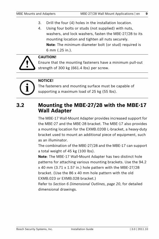
3. Drill the four (4) holes in the installation location.4. Using four bolts or studs (not supplied) with nuts,
washers, and lock washers, fasten the MBE-27/28 to its mounting location and tighten all nuts securely. Note: The minimum diameter bolt (or stud) required is 6 mm (.25 in.).
3.2 Mounting the MBE-27/28 with the MBE-17 Wall AdapterThe MBE-17 Wall-Mount Adapter provides increased support for the MBE-27 and the MBE-28 bracket. The MBE-17 also provides a mounting location for the EXMB.020B L-bracket, a heavy-duty bracket used to mount an additional piece of equipment, such as an illuminator. The combination of the MBE-27/28 and the MBE-17 can support a total weight of 45 kg (100 lbs). Note: The MBE-17 Wall-Mount Adapter has two distinct hole patterns for attaching various mounting brackets. Use the 94.2 x 40 mm (3.71 x 1.57 in.) hole pattern with the MBE-27/28 bracket. (Use the 86 x 40 mm hole pattern with the old EXMB.023 or EXMB.028 bracket.)Refer to Section 6 Dimensional Outlines, page 20, for detailed dimensional drawings.
CAUTION! Ensure that the mounting fasteners have a minimum pull-out strength of 300 kg (661.4 lbs) per screw.
NOTICE! The fasteners and mounting surface must be capable of supporting a maximum load of 25 kg (55 lbs).

10 en | MBE-27/28 Wall Mount Applications MBE Mounts and Adapters
| 3.0 | 2011.10 Installation Guide Bosch Security Systems, Inc.
1. Determine a secure mounting location for the wall installation.
2. Use the six (6) holes on the flanges of the MBE-17 wall-mount adapter as a template to mark the position where the holes should be drilled to secure the adapter.MBE-28: If routing cables through the wall, use the center hole on the MBE-17 as a template to drill through the wall.
3. Drill the six (6) holes in the installation location, bolts not supplied.Note: The minimum diameter bolt (or stud) required is 6 mm (.25 in.).
4. Orient the MBE-17 so that the 94.2 x 40.0 mm (3.71 x 1.57 in.) hole pattern is at the top.
5. Using six bolts (or studs) with nuts, washers, and lock washers, fasten the MBE-17 to its mounting location and tighten all nuts securely.
6. Align the four holes on the MBE-27B, MBE-27W, or the MBE-28B bracket with the 94.2 x 40 mm (3.71 x 1.57 in.) hole pattern on the MBE-17 adapter.
CAUTION! Ensure that the mounting fasteners have a minimum pull-out strength of 300 kg (661.4 lbs) per screw
NOTICE! The fasteners and mounting surface must be capable of supporting a maximum load of 45 kg (100 lbs).

MBE Mounts and Adapters MBE-27/28 Wall Mount Applications | en 11
Bosch Security Systems, Inc. Installation Guide | 3.0 | 2011.10
7. Fasten the MBE-27 or MBE-28 bracket to the MBE-17 using the four (4) M6 x 20 hex bolts and washers that shipped with the MBE-17. Use the illustration below as a guide:
8. Optionally, attach the EXMB.020B to the MBE-17 using the two (2) M6 x 20 hex bolts that shipped with the EXMB.020B. Use the illustration below as a guide:

12 en | MBE-27/28 Pole Mount Applications MBE Mounts and Adapters
| 3.0 | 2011.10 Installation Guide Bosch Security Systems, Inc.
4 MBE-27/28 Pole Mount ApplicationsThe MBE-27B, MBE-27W, and the MBE-28B Brackets can be mounted to pole using the MBE-15 Pole-Mount Adapter. The MBE-15 Pole-Mount Adapter comes with two (2) metal bands and a connected gear clamp that secures the MBE-15 to a pole. The MBE-15 Pole-Mount Adapter can accommodate a pole with a diameter of 89–203 mm (3.5–8 in.), extra straps can be used for larger pole diameters (not-supplied).The MBE-15 also provides a mounting location for the EXMB.020B bracket, a heavy-duty L-bracket used to mount an additional piece of equipment, such as an illuminator. The combination of the MBE-27/28 and the MBE-15 can support a total weight of 90 kg (200 lbs). Note: The MBE-15 Pole-Mount Adapter has two distinct hole patterns for attaching various mounting brackets. Use the 94.2 x 40 mm (3.71 x 1.57 in.) hole pattern with the MBE-27/28 bracket. (Use the 86 x 40 mm hole pattern with the old EXMB.023 or EXMB.028 bracket.)Refer to Section 6 Dimensional Outlines, page 20, for dimensional drawings of each mount and adapter.1. Determine a secure mounting location for the pole
installation2. Orient the MBE-15 so that the 94.2 x 40 mm
(3.71 x 1.57 in.) hole pattern is at the top.3. Thread one end of one of the metal band through the two
top slots of the MBE-15. Then, wrap the metal band around the pole and thread the end of the metal band into the gear clamp.
4. Tighten the gear clamp using a flat screwdriver or an 8 mm hex socket driver until the metal band is securely fastened to the pole.
5. Thread one end of the other metal band through the two bottom slots of the MBE-15. Then, wrap the metal band around the pole and thread the end of the metal band into the gear clamp.

MBE Mounts and Adapters MBE-27/28 Pole Mount Applications | en 13
Bosch Security Systems, Inc. Installation Guide | 3.0 | 2011.10
6. Tighten the gear clamp using a flat screwdriver or an 8 mm hex socket driver until the metal band is securely fastened to the pole.
7. Align the four holes on the MBE-27B, MBE-27W, or the MBE-28B bracket with the 94.2 x 40 mm (3.71 x 1.57 in.) hole pattern on the MBE-15 adapter.
8. Fasten the MBE-27 or MBE-28 bracket to the MBE-15 using the four (4) M6 x 20 hex bolts and washers that shipped with the MBE-15. Use the illustration below as a guide:

14 en | MBE-27/28 Pole Mount Applications MBE Mounts and Adapters
| 3.0 | 2011.10 Installation Guide Bosch Security Systems, Inc.
9. Optionally, attach the EXMB.020B to the MBE-15 using the two (2) M6 x 20 hex bolts that shipped with the EXMB.020B. Use the illustration below as a guide:
MBE Mounts and Adapters Attaching Cameras to the Brackets | en 15
Bosch Security Systems, Inc. Installation Guide | 3.0 | 2011.10
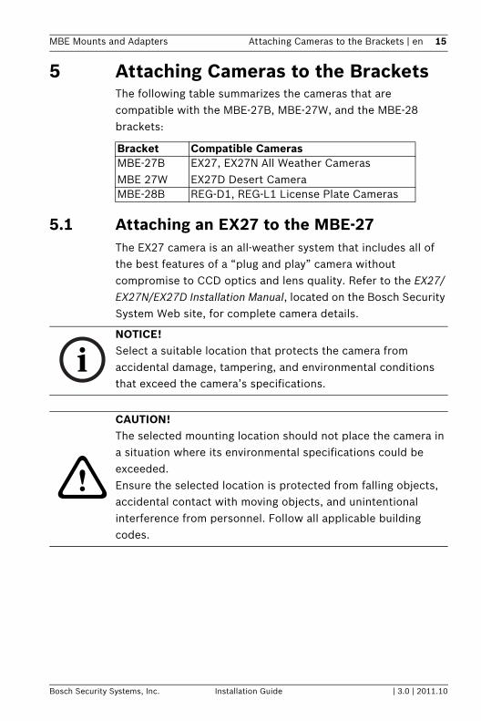
5 Attaching Cameras to the BracketsThe following table summarizes the cameras that are compatible with the MBE-27B, MBE-27W, and the MBE-28 brackets:
5.1 Attaching an EX27 to the MBE-27The EX27 camera is an all-weather system that includes all of the best features of a “plug and play” camera without compromise to CCD optics and lens quality. Refer to the EX27/EX27N/EX27D Installation Manual, located on the Bosch Security System Web site, for complete camera details.
Bracket Compatible CamerasMBE-27BMBE 27W
EX27, EX27N All Weather CamerasEX27D Desert Camera
MBE-28B REG-D1, REG-L1 License Plate Cameras
NOTICE! Select a suitable location that protects the camera from accidental damage, tampering, and environmental conditions that exceed the camera’s specifications.
CAUTION! The selected mounting location should not place the camera in a situation where its environmental specifications could be exceeded.Ensure the selected location is protected from falling objects, accidental contact with moving objects, and unintentional interference from personnel. Follow all applicable building codes.

16 en | Attaching Cameras to the Brackets MBE Mounts and Adapters
| 3.0 | 2011.10 Installation Guide Bosch Security Systems, Inc.
Use the following illustration to identify the parts of the MBE-27 bracket:
Figure 5.1 MBE-27 Bracket with MBE-17 Wall-Mount Adapter
Use the following procedure to mount an EX27 camera:1. Attach the MBE-27 Bracket to a wall or a pipe according to
the instructions in Section 3 MBE-27/28 Wall Mount Applications, page 8, or Section 4 MBE-27/28 Pole Mount Applications, page 12.
2. Position the interface plate (item 2 in Figure 5.1) on the bracket.
3. Place the pan/tilt mounting bracket connected to the EX27 camera onto the interface plate (item 2) on the MBE-27.
4. Feed the M8 x 45 mm bolt through the bracket (item 1) and the interface plate (item 2) and into the pan/tilt mounting bracket.
5. Use the #6 hex key to tighten the M8 x 45 mm bolt (Item 3) and to secure the EX27 camera to the MBE-27 bracket.
1 MBE-27 Bracket 3 M8 x 45 mm bolt2 Interface Plate 4 Hole Plugs

MBE Mounts and Adapters Attaching Cameras to the Brackets | en 17
Bosch Security Systems, Inc. Installation Guide | 3.0 | 2011.10
6. Route the applicable wires to the EX27 camera. Remove any of the hole plugs (item 4) to facilitate cable management.
7. Refer to the EX27/EX27N/EX27D Installation Manual to configure and to use the camera.
5.2 Attaching a REG-D1/L1 to an MBE-28The REG-D1 and REG-L1 License Plate Capture Cameras are designed and configured to capture images of license plates under a wide range of ambient light and weather conditions. Refer to the REG-D1 Installation Instructions or to the REG-L1 Installation Instructions, both located on the Bosch Security System Web site, for complete camera details.
NOTICE! Select a suitable location that protects the camera from accidental damage, tampering, and environmental conditions that exceed the camera’s specifications.
CAUTION! The selected mounting location should not place the camera in a situation where its environmental specifications could be exceeded.Ensure the selected location is protected from falling objects, accidental contact with moving objects, and unintentional interference from personnel. Follow all applicable building codes.

18 en | Attaching Cameras to the Brackets MBE Mounts and Adapters
| 3.0 | 2011.10 Installation Guide Bosch Security Systems, Inc.
Use the following illustration to identify the parts of the MBE-27 bracket:
Figure 5.2 MBE-28 Bracket with MBE-17 Wall-Mount Adapter
Use the following procedure to mount a REG-D1 or REG-L1 camera:1. Attach the MBE-28B Bracket to a wall or a pole according
to the instructions in Section 3 MBE-27/28 Wall Mount Applications, page 8, or Section 4 MBE-27/28 Pole Mount Applications, page 12.
2. Route the cable attached to the REG-D1 or REG-L1 camera through the MBE-28B and into the wall or through one of the plugs to facilitate cable management.
3. Align the six (6) inner screw holes on the REG-D1 or REG-L1 with the bolt holes on the bracket mounting head.
1 MBE-28 Bracket 4 Tilt Bolt2 Bracket Mounting Head 5 Locking Bolt3 Hole Plugs

MBE Mounts and Adapters Attaching Cameras to the Brackets | en 19
Bosch Security Systems, Inc. Installation Guide | 3.0 | 2011.10
4. Secure the REG-D1 or REG-L1 to the MBE-28B using the six (6) M5 x 10 mm bolts with captive washers and the #4 hex key.
5. Adjust the tilt angle of the camera by loosening the tilt bolt (item 4) with the #5 hex key and the locking bolt (item 5) with a Phillips head screwdriver.
6. Place the camera at the desired tilt angle and tighten the tilt bolt and the locking bolt.
7. Adjust the pan angle of the camera by loosening the pan bolt, located beneath the bracket mounting head, by loosening the pan bolt using the #5 hex key. Place the camera at the desired pan angle and tighten the bolt.
8. Refer to the REG-D1 Installation Instructions or to the REG-L1 Installation Instructions to configure and use the camera.
20 en | Dimensional Outlines MBE Mounts and Adapters
| 3.0 | 2011.10 Installation Guide Bosch Security Systems, Inc.
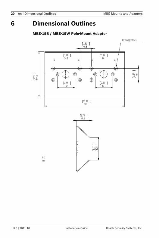
6 Dimensional OutlinesMBE-15B / MBE-15W Pole-Mount Adapter
80.5
3.17
44.51.75
401.57
159.86.2
9
28111.06
622.44
622.44
94.23.71
863.39
40.81.61
M6 Thread Typ 12 Places
[in.]mm

MBE Mounts and Adapters Dimensional Outlines | en 21
Bosch Security Systems, Inc. Installation Guide | 3.0 | 2011.10
MBE-17B / MBE-17W Wall-Mount Adapter
401.57
28111.06
421.65
421.65
140.55.53
194
7.64
863.39
94.23.71
622.44
622.44
40.81.61
168
6.61
48.31.90
218
8.58
[in.]mm

22 en | Dimensional Outlines MBE Mounts and Adapters
| 3.0 | 2011.10 Installation Guide Bosch Security Systems, Inc.
MBE-27B / MBE-27W Bracket
233.509.193
102
4.01
6
40[1.568]
94.1
73.
708
122.
954.
841
692.717
Ø58
2.283 2078.150
[in.]mm

MBE Mounts and Adapters Dimensional Outlines | en 23
Bosch Security Systems, Inc. Installation Guide | 3.0 | 2011.10
MBE-28B Bracket
[in]
mm
90
3.54
73.4
2.89
171.46.7
5
233.5
9.19
94.17
[3.70
8]
40
1.57
73
2.87
63
2.48

24 en | Dimensional Outlines MBE Mounts and Adapters
| 3.0 | 2011.10 Installation Guide Bosch Security Systems, Inc.


Bosch Security Systems, Inc.850 Greenfield RoadLancaster, PA 17601U.S.A.www.boschsecurity.com © Bosch Security Systems, Inc., 2011