mc-1100 series quick installation guide · the mc-1100 (mc-1111 and mc -1121 series) has an sd slot...
TRANSCRIPT

P/N: 1802011000023
*1802011000023*
MC-1100 Series Quick Installation Guide
Edition 3.0, February 2018
Technical Support Contact Information www.moxa.com/support
Moxa Americas: Toll-free: 1-888-669-2872 Tel: 1-714-528-6777 Fax: 1-714-528-6778
Moxa China (Shanghai office): Toll-free: 800-820-5036 Tel: +86-21-5258-9955 Fax: +86-21-5258-5505
Moxa Europe: Tel: +49-89-3 70 03 99-0 Fax: +49-89-3 70 03 99-99
Moxa Asia-Pacific: Tel: +886-2-8919-1230 Fax: +886-2-8919-1231
Moxa India: Tel: +91-80-4172-9088 Fax: +91-80-4132-1045
2018 Moxa Inc. All rights reserved.

- 2 -
Overview The Moxa MC-1100 Series DIN-rail mountable, fanless, x86 embedded computers are based on the Intel® Atom™ E3800 Series processor. These computers feature the most reliable I/O design to maximize connectivity and support multiple wireless modules (Wi-Fi/3G/LTE), making them suitable for a diverse range of communication applications.
Powered by a wide operating temperature range (-40 to 70°C) and Safety/EMI/EMS compliances, the MC-1100 Series is ideal for intelligent computing and communication solutions in critical environments, including marine communication, Oil & Gas field site monitoring, and transportation.
The MC-1100 Series comes with hardware monitoring features built in for device I/O status monitoring and alerts, system temperature monitoring and alerts, and system power management. Monitoring system status closely makes it easier to recover from errors and provides the most reliable platform for your applications.
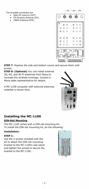
Package Checklist Before installing the MC-1100, verify that the package contains the following items:
• MC-1100 embedded computer • Terminal block to power jack converter • DIN-rail mounting kit • Quick installation guide (printed) • Documentation • Warranty card
Please notify your sales representative if any of the above items are missing or damaged.
MC-1111 Panel Layout The following figures show the panel layouts of the MC-1111 Series:
Top View Front View
- 3 -
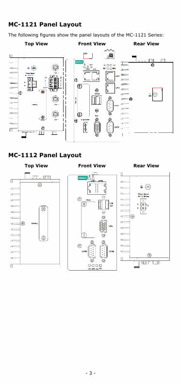
MC-1121 Panel Layout
The following figures show the panel layouts of the MC-1121 Series:
Top View Front View Rear View
MC-1112 Panel Layout
Top View Front View Rear View
- 4 -
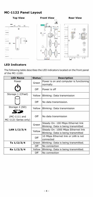
MC-1122 Panel Layout
Top View Front View Rear View
LED Indicators
The following table describes the LED indicators located on the front panel of the MC-1100:
LED Name Status Description Power
Green Power is on and computer is functioning normally
Off Power is off
Storage 1 (CFast)
Yellow Blinking: Data transmission
Off No data transmission.
Storage 2 (SD)
(MC-1111 and
MC-1121 Series only)
Yellow Blinking: Data transmission
Off No data transmission
LAN 1/2/3/4
Green Steady On: 100 Mbps Ethernet link Blinking: Data is being transmitted
Yellow Steady On: 1000 Mbps Ethernet link Blinking: Data is being transmitted
Off 10 Mbps Ethernet link or LAN is not connected
Tx 1/2/3/4
Green Blinking: Data is being transmitted. Off No connection
Rx 1/2/3/4
Yellow Blinking: Data is being transmitted. Off No connection
- 5 -
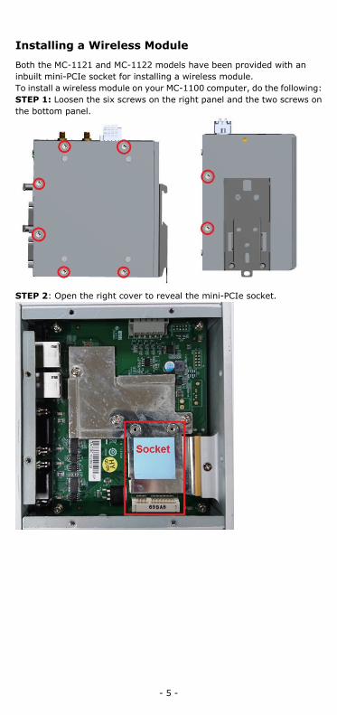
Installing a Wireless Module
Both the MC-1121 and MC-1122 models have been provided with an inbuilt mini-PCIe socket for installing a wireless module. To install a wireless module on your MC-1100 computer, do the following: STEP 1: Loosen the six screws on the right panel and the two screws on the bottom panel.
STEP 2: Open the right cover to reveal the mini-PCIe socket.
- 6 -
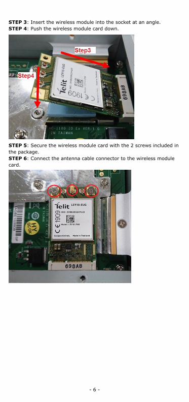
STEP 3: Insert the wireless module into the socket at an angle. STEP 4: Push the wireless module card down.
STEP 5: Secure the wireless module card with the 2 screws included in the package. STEP 6: Connect the antenna cable connector to the wireless module card.
- 7 -
STEP 7: Replace the side and bottom covers and secure them with screws. STEP 8: (Optional) You can install external 3G, 4G, and Wi-Fi antennas from Moxa to increase the wireless coverage. Contact a Moxa sales representative for details. A MC-1100 computer with external antennas installed is shown here.
Installing the MC-1100 DIN-Rail Mounting The MC-1100 comes with a DIN-rail mounting kit. To install the DIN-rail mounting kit, do the following:
Installation:
STEP 1: Use the 4 screws included with the kit to attach the DIN-rail mounting bracket to the MC-1100’s rear panel and tighten the screws to secure the bracket to the MC-1100.
- 8 -
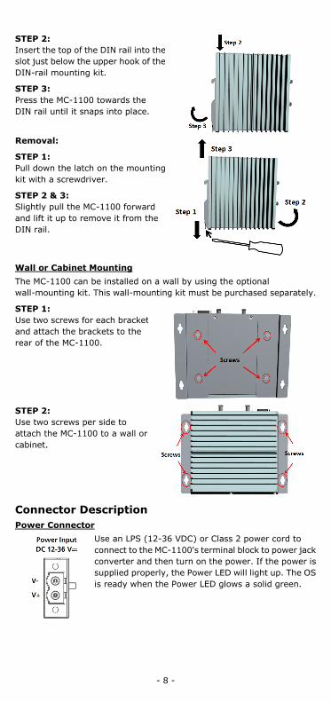
STEP 2: Insert the top of the DIN rail into the slot just below the upper hook of the DIN-rail mounting kit.
STEP 3: Press the MC-1100 towards the DIN rail until it snaps into place.
Removal:
STEP 1: Pull down the latch on the mounting kit with a screwdriver.
STEP 2 & 3: Slightly pull the MC-1100 forward and lift it up to remove it from the DIN rail.
Wall or Cabinet Mounting The MC-1100 can be installed on a wall by using the optional wall-mounting kit. This wall-mounting kit must be purchased separately.
STEP 1: Use two screws for each bracket and attach the brackets to the rear of the MC-1100.
STEP 2: Use two screws per side to attach the MC-1100 to a wall or cabinet.
Connector Description Power Connector
Use an LPS (12-36 VDC) or Class 2 power cord to connect to the MC-1100's terminal block to power jack converter and then turn on the power. If the power is supplied properly, the Power LED will light up. The OS is ready when the Power LED glows a solid green.
- 9 -
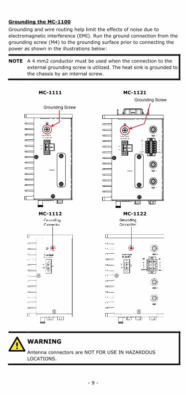
Grounding the MC-1100 Grounding and wire routing help limit the effects of noise due to electromagnetic interference (EMI). Run the ground connection from the grounding screw (M4) to the grounding surface prior to connecting the power as shown in the illustrations below:
NOTE A 4 mm2 conductor must be used when the connection to the external grounding screw is utilized. The heat sink is grounded to the chassis by an internal screw.
MC-1111 MC-1121
MC-1112 MC-1122
WARNING
Antenna connectors are NOT FOR USE IN HAZARDOUS LOCATIONS.
- 10 -
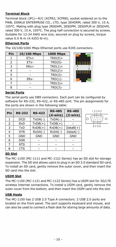
Terminal Block Terminal block (JP1)—R/C (XCFR2, XCFR8), socket soldered on to the PWB, DINKLE ENTERPRISE CO., LTD, type 2EHDRM, rated 300 V, 15 A, 105°C. Mating with plug type 2RSDAM, 2ESDPM, 2ESDPLM or 2ESDVM, rated 300 V, 15 A, 105°C. The plug half connection is secured by screws. Suitable for 12-24 AWG wire size, secured on plug by screws, torque value 0.5 N-m (4.4253 lb-in). Ethernet Ports The 10/100/1000 Mbps Ethernet ports use RJ45 connectors.
Pin 10/100 Mbps 1000 Mbps 1 ETx+ TRD(0)+ 2 ETx- TRD(0)- 3 ERx+ TRD(1)+ 4 – TRD(2)+ 5 – TRD(2)- 6 ERx- TRD(1)- 7 – TRD(3)+ 8 – TRD(3)-
Serial Ports The serial ports use DB9 connectors. Each port can be configured by software for RS-232, RS-422, or RS-485 port. The pin assignments for the ports are shown in the following table:
Pin RS-232 RS-422 RS-485 (4-wire)
RS-485 (2-wire)
1 DCD TxDA(-) TxDA(-) – 2 RxD TxDB(+) TxDB(+) – 3 TxD RxDB(+) RxDB(+) DataB(+) 4 DTR RxDA(-) RxDA(-) DataA(-) 5 GND GND GND GND 6 DSR – – – 7 RTS – – – 8 CTS – – –
SD Slot The MC-1100 (MC-1111 and MC-1121 Series) has an SD slot for storage expansion. The SD slot allows users to plug in an SD 3.0 standard SD card. To install an SD card, gently remove the outer cover, and then insert the SD card into the slot.
USIM Slot The MC-1100 (MC-1121 and MC-1122 Series) has a USIM slot for 3G/LTE wireless Internet connections. To install a USIM card, gently remove the outer cover from the bottom, and then insert the USIM card into the slot.
USB Hosts The MC-1100 has 2 USB 2.0 Type A connectors. 2 USB 2.0 ports are located on the front panel. The port supports keyboard and mouse, and can also be used to connect a flash disk for storing large amounts of data.
- 11 -
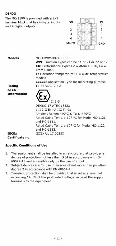
DI/DO The MC-1100 is provided with a 2x5 terminal block that has 4 digital inputs and 4 digital outputs.
Models MC-11WW-XX-Y-ZZZZZ WW: Function Type: can be 11 or 21 or 22 or 12 XX: Performance Type: E2 = Atom E3826, E4 = Atom E3845 Y: Operation temperature; T = wide-temperature models ZZZZZ: Application Type for marketing purpose
Rating 12-36 VDC, 2.5 A ATEX Information
II 3 G DEMKO 17 ATEX 1852X e II 3 G Ex nA IIC T4 Gc Ambient Range: -40°C ≤ Ta ≤ +70°C Rated Cable Temp.≥ 107 °C for Model MC-1121 and MC-1111. Rated Cable Temp.≥ 107°C for Model MC-1122 and MC-1112.
IECEx Certificate no.
IECEx UL 17.0025X
Specific Conditions of Use 1. The equipment shall be installed in an enclosure that provides a
degree of protection not less than IP54 in accordance with EN 60079-15 and accessible only by the use of a tool.
2. Subject devices are for use in an area of not more than pollution degree 2 in accordance with EN 60664-1.
3. Transient protection shall be provided that is set at a level not exceeding 140 % of the peak rated voltage value at the supply terminals to the equipment.