mc³ 30.10.ex weigh feeder controller - merrick-inc.com manual 3010e.pdf · system overview ......
TRANSCRIPT

MC³ 30.10.EX Weigh Feeder Controller
Operation and Maintenance Manual Version E Merrick Industries, Inc 10 Arthur Drive Lynn Haven, FL 32444 Ph. +1 850.265.3611 Fax +1 850.265.9768 Web http://www.merrick-inc.com

Revisions O February 22, 1999 Original A February 4, 2000 Updated for New Version B October 14, 2000 Updated for Version B D Sept 17, 2001 Updated for Version D E June 3, 2004 Updated for Version E PROPRIETARY NOTE The information in this manual, including technical data and copies of drawings, embodies information proprietary to Merrick Industries, Incorporated. This manual is provided to the user of equipment purchased from Merrick Industries, Inc. for use only in operation or maintenance of such equipment. Such information in this manual is not to be used, disclosed, copied, or reproduced in whole or part for any use other than that indicated above, or for any other purpose detrimental to the interests of Merrick Industries, Inc. Patents owned by Merrick Industries, Inc. have been issued or are pending on at least some of the information in this manual, and unauthorized use of this subject matter of such patents is a violation of such patents and is prohibited
30.10.EX O&M Manual i
CONTENTS Introduction ................................................................................................................................................... 3
Safety........................................................................................................................................................ 3 In General ............................................................................................................................................. 3 Electrical Precautions........................................................................................................................... 3
Related Publications................................................................................................................................. 3 Manual Conventions................................................................................................................................. 3
Screens ................................................................................................................................................ 4 Solving Problems...................................................................................................................................... 4
Technical Support................................................................................................................................. 4 System Overview .......................................................................................................................................... 5
Dynamic Control ....................................................................................................................................... 5 Key parameters .................................................................................................................................... 6
Digital ControL .......................................................................................................................................... 8 Feeder States ....................................................................................................................................... 8 Digital Control Parameters ................................................................................................................... 9 Feeder State Transitions .................................................................................................................... 10
Hardware..................................................................................................................................................... 11 Getting Started ............................................................................................................................................ 12
Installation............................................................................................................................................... 12 Starting the controller ............................................................................................................................. 12
Quick Setup ........................................................................................................................................ 12 Main Screens.......................................................................................................................................... 13
Feeder Screen.................................................................................................................................... 13 Graph Screen ..................................................................................................................................... 15 Numeric Screen.................................................................................................................................. 15 Warnings ............................................................................................................................................ 16 Faults .................................................................................................................................................. 17
Setting the Setpoint ................................................................................................................................ 17 Actions .................................................................................................................................................... 20
Feeder Start and Stop buttons ........................................................................................................... 20 Clean Off Screen ................................................................................................................................ 21 Reset Sub-Total.................................................................................................................................. 21 Reset G-Total ..................................................................................................................................... 21 Diag Menu .......................................................................................................................................... 21 Home Screen...................................................................................................................................... 21 Calibrate Menu ................................................................................................................................... 21 Printer Menu ....................................................................................................................................... 21 Settings Menu..................................................................................................................................... 23
Setting Up Your Controller .......................................................................................................................... 24 Settings Menu Items............................................................................................................................... 25
Select Units ........................................................................................................................................ 25 Set Dec Pts......................................................................................................................................... 25 Design Capacities............................................................................................................................... 25 Control Settings .................................................................................................................................. 26 Hopper Settings.................................................................................................................................. 28 Stability Settings ................................................................................................................................. 30 Calibrate Settings ............................................................................................................................... 30 Quick Setup ........................................................................................................................................ 31 Sample Rate....................................................................................................................................... 32 Dampening & Display......................................................................................................................... 32 Set Date and Time.............................................................................................................................. 33
Inputs and Outputs Menu ....................................................................................................................... 33 Analog Inputs Setup ........................................................................................................................... 33 Analog Outputs Setup ........................................................................................................................ 35

30.10.EX O&M Manual ii
Digital I/O Mapping ............................................................................................................................. 37 EMT Settings ...................................................................................................................................... 47 Comm Settings ................................................................................................................................... 47 Limit Switches..................................................................................................................................... 48
Calibrating Your Controller.......................................................................................................................... 51 Calibration Menu ................................................................................................................................ 51 Material Calibration............................................................................................................................. 53 Weight Procedure............................................................................................................................... 53 Start Learning ..................................................................................................................................... 58
Diagnosing Problems.................................................................................................................................. 61 Diagnostic Menus ................................................................................................................................... 61
HPAD Diagnostics .............................................................................................................................. 61 Communication Diagnostics............................................................................................................... 62 Calib History Display .......................................................................................................................... 63 Analog Diagnostics............................................................................................................................. 64 Digital Diagnostics .............................................................................................................................. 64 Faults and Warnings Diagnostics....................................................................................................... 65 Register Monitor ................................................................................................................................. 66 Misc Data Diagnostics........................................................................................................................ 66
Diagnostic Settings................................................................................................................................. 67 HPAD Settings.................................................................................................................................... 68 Passwords .......................................................................................................................................... 69 Register Editor.................................................................................................................................... 69
30.10.EX O&M Manual 3
INTRODUCTION
SAFETY The Merrick MC³ Controller is used for the control of process weighing equipment. To insure personnel safety please read the following instructions and precautions carefully.
In General 1. Observe all standard precautions that pertain to moving machinery. 2. Observe all standard precautions that pertain to electrical drives and electrical
controls. 3. Pay particular attentions to special notes and precautions that appear throughout
this manual. 4. Please read and familiarize yourself with this entire manual before attempting
service or repair of the Merrick MC³ Controller. If you have any questions or problems please call the Merrick Service Department for assistance.
Electrical Precautions 1. Before undertaking work on the electrical system, the drives, or the Controller,
open the main-disconnect switches and lock boxes. Work should never be performed on the Controller with power on the unit. It is recommended to disconnect the power from the controller before attempting any service procedure.
2. Verify that all grounds that are called for on the wiring diagrams are in place and are securely connected. Proper grounding not only helps insure your personal safety, but also is necessary for the proper operation of the controller.
3. If it is necessary that you must work in or near areas of live high voltage, always keep one hand clear of the machine, the cabinet, or any other conductors to avoid the possibility of electrical shock traveling across your chest. NEVER undertake any electrical work in areas with wet or flooded standing areas.
4. NEVER impair or disable the function of a fuse or a circuit breaker. IF YOU ARE IN DOUBT ABOUT ANY PROCEDURE, CONTACT THE MERRICK SERVICE DEPARTMENT.
RELATED PUBLICATIONS You will find related publications regarding MC³ controller hardware, internal register database information and industrial networking capabilities at the support web site at http://www.merrick-inc.com/mct. In the rest of the manual, this is referred to as [MCT].
MANUAL CONVENTIONS NOTE: Any additional information that may be useful follows the note marker. CAUTION: Be careful, certain settings may cause problems. WARNING: Follow the directions prescribed in the warning. Serious problems can occur if the
recommendations are not followed.
30.10.EX O&M Manual 4
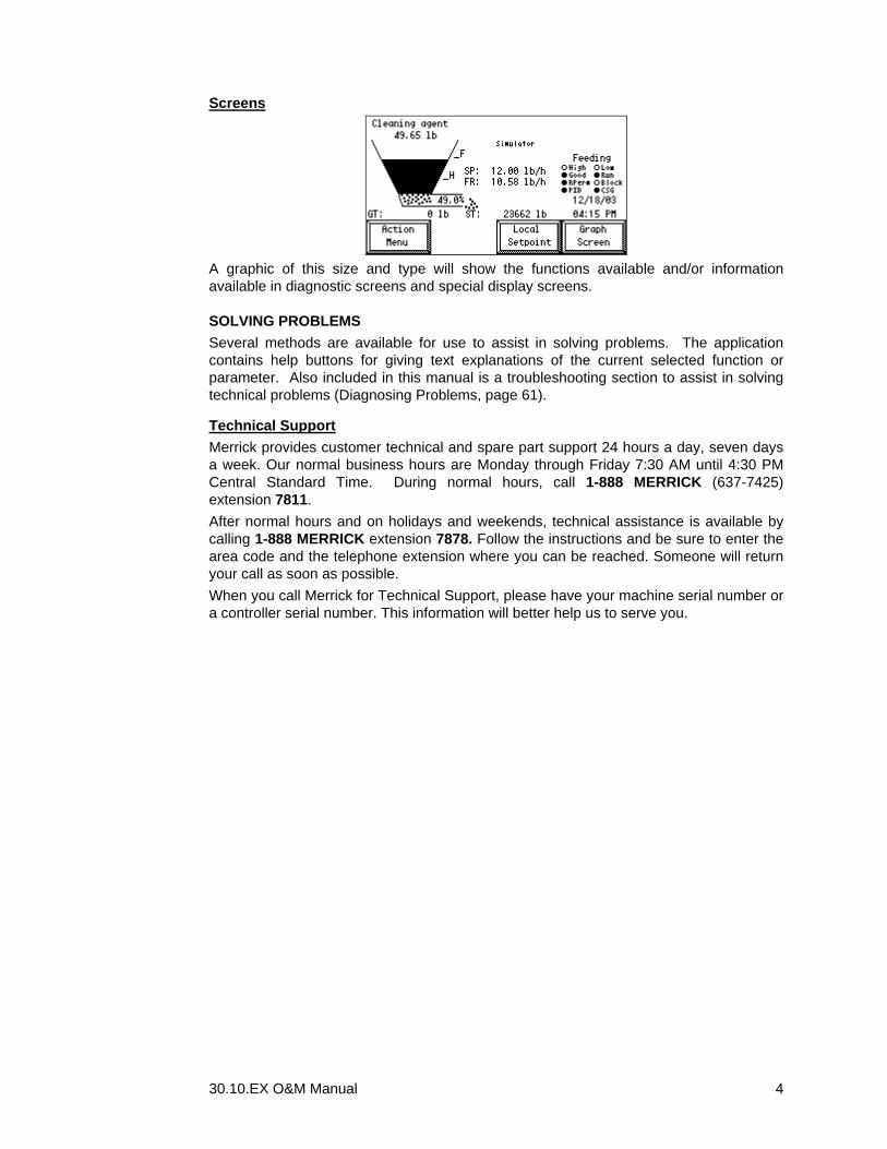
Screens
A graphic of this size and type will show the functions available and/or information available in diagnostic screens and special display screens.
SOLVING PROBLEMS Several methods are available for use to assist in solving problems. The application contains help buttons for giving text explanations of the current selected function or parameter. Also included in this manual is a troubleshooting section to assist in solving technical problems (Diagnosing Problems, page 61).
Technical Support Merrick provides customer technical and spare part support 24 hours a day, seven days a week. Our normal business hours are Monday through Friday 7:30 AM until 4:30 PM Central Standard Time. During normal hours, call 1-888 MERRICK (637-7425) extension 7811. After normal hours and on holidays and weekends, technical assistance is available by calling 1-888 MERRICK extension 7878. Follow the instructions and be sure to enter the area code and the telephone extension where you can be reached. Someone will return your call as soon as possible. When you call Merrick for Technical Support, please have your machine serial number or a controller serial number. This information will better help us to serve you.

30.10.EX O&M Manual 5
SYSTEM OVERVIEW A Loss-In-Weight Feeder system is designed to feed material out of a hopper at a desired feedrate. The hopper is placed on load cells, producing a signal proportional to the weight of the hopper and its content. At the bottom, there is a variable speed feeding device, such as a material screw or a vibrating pan. The MC³ controller will calculate the feedrate from the rate of loss of the weight and attempt to maintain the feedrate at the desired value (the setpoint) by varying the speed of the feeding device. When the weight of the hopper content reaches a pre-set low weight, called the Heel Point, the MC³ controller will call for the hopper to be filled, up to another pre-set weight, called the Fill Point. During the filling, the feedrate can not be calculated, and the speed of the feeding device will be controlled based on inferred values.
DYNAMIC CONTROL The MC³ 30.10.EX controller uses two different control algorithms that normally compete with each other for the control of the feeding device. The PID (Proportional, Integral, and Derivative) control algorithm is suitable for high feedrates and stable weight values. The CSG (Conditional Step Gravimetric) control algorithm is suitable for slow feedrates and when occasional disturbances in the weight signal are present. Most applications fall in between the two categories. By keeping both algorithms active, and letting an arbitrating algorithm determine to which degree the PID and CSG are allowed to control the speed of the feeding device, it is possible to take advantage of the desired properties of both. For very slow or very fast feeders however, it is better to use only CSG or only PID control.
Setpoint Signal Load Cell Signal
Weight Signal Conditioning
Setpoint Signal Conditioning
Weight Filter Setpoint Filter
Loss Calculation _
PID Control
Method Arbitrator
CSG Control
Dynamic Protection
Speed Demand Signal
Setpoint
Average Setpoint
Weight
Average Weight
Weight Loss

30.10.EX O&M Manual 6
Key parameters Each of the function blocks has one or more parameters associated with it. They all have to be set properly for good feedrate control. Most of them can be set automatically, by running Quick Setup (see page 31). A Learning Cycle can also be used to further improve system tuning. See Start Learning on page 58. Some of them can be continuously updated by the controller itself, as a part of a self-adjusting scheme. See the Autotune and Auto FF Adjust logical inputs under List of Logical Inputs on page 39.
Weight Signal Conditioning The weight signal conditioning block takes the Load Cell Signal as input, passes through an A/D converter, called the HPAD, and produces a weight value as an output. Parameters are: Zero Weight The weight of the hopper, feeding device etc when the hopper is
empty. Set by running a Zeroing Procedure (page 52). You can also set it manually. See Zero Weight on page 30.
Scale Factor A divisor to translate the load cell signal counts from the load cell A/D converter, the HPAD, to usable engineering units, such as lb or kg. Set by running a Material Calibration (page 53) Weight Procedure (page 53) or Electronic Calibration (page 55). You can also set it manually. See Scale Factor on page 30.
Sample Time How often the controller re-calculates all internal variables. Set by Quick Setup (page 31), or Start Learning (page 58) or manually. See Sample Rate on page 32. The slower the feedrate, the longer the sample time.
Weight Filter The weight produced by the Weight Signal Conditioning block is normally not usable for determining the weight loss. An averaging filter is used to produce a smoother value suitable for this purpose. It takes the Weight as input and produces the ‘Average Weight’ as output, by calculating the arithmetic average of a settable number of samples. There is only one parameter: Average Slot How many weight samples used to form the Average Weight. Set by
Quick Setup (page 31), Start Learning (page 58) or manually. See Average Slots, on page 27. The slower the feeder, the more the slots. If the Autotune Input is turned on, this parameter is adjusted, based on statistics from the last weigh cycle, at the start of each Fill sequence.
Loss Calculation Here is where the Weight Loss is calculated, by taking the difference between two samples of the Average Weight. There is only one parameter. It is normally set to the same value as the Average Slot. Loss slots How many samples the two Average Weight values are separated to
calculate the Weight Loss. Set by Quick Setup (page 31), Start Learning (page 58) or manually. See Loss Slots on page 27. If the Autotune Input is turned on, this parameter is adjusted, based on statistics from the last weigh cycle, at the start of each Fill Sequence.
Setpoint Signal Conditioning If analog signals are used, the Setpoint has to be calculated in a similar way as the Weight. The analog Setpoint signal taken as input passes through an A/D converter and produces a Setpoint Feedrate as an output. Parameters are:

30.10.EX O&M Manual 7
SP Lo Cnts A value in counts from the A/D converter representing a Minimum setpoint. Set by the Analog procedure, page 57, or in the Analog Setpoint menu. See page 34.
SP Hi Cnts A value in counts from the A/D converter representing a Maximum setpoint. Also set by the Analog procedure, page 57, or in the Analog Setpoint menu. See page 34.
SP Min Value This is the minimum setpoint value, normally zero. Set in the Analog Setpoint menu. See page 34.
SP Max Value This is the maximum setpoint value, normally the same as the Design Feedrate for the feeder. Set in the Analog Setpoint menu. See page 34.
Setpoint filter When using CSG control, a fluctuating setpoint is undesirable. To avoid fluctuations due to noise on analog signals or in follower implementations, this averaging filter can be used to produce a smoother value. It takes the Feedrate Setpoint as input and produces the ‘Average Setpoint’ as output, by calculating the arithmetic average of a settable number of samples. There is only one parameter: Setpoint Filter How many setpoint samples used to form the Average Setpoint. Set
by Quick Setup (page 31), Start Learning (page 58) or manually. See Dampening & Display on page 32.
PID Controller This is a classic Proportional, Integral and Derivative control algorithm, taking the difference between the Feedrate Setpoint and the Weight loss as an error input, and producing a demand signal (to control the feeding device speed) as an output. PID control works well when there are no disturbances on the weight signal. The feeding device does not necessarily have to be linear and repeatable. There are three parameters, Gain, Integral and Derivative, described in detail in Control Settings on page 26. If the Autotune Input is turned on, the parameters are adjusted, based on statistics from the last weigh cycle, at the start of each Fill sequence.
CSG Controller The Conditional Step Gravimetric control algorithm maintains a model of the efficiency of the feeding device, resulting in a parameter called the Feedfactor. It is defined as “The Speed Demand Signal required for feeding at Design Feedrate”. A Feed Factor greater than 100% indicates that the Design Feedrate can not be reached, because the feeding device is not efficient enough. A feedfactor of less than 60% indicates that the capacity of the feeding device is too high. The Feed Factor is only modified when the Weight Loss signal is stable. The demand output, produced by the control algorithm, is calculated as the Setpoint multiplied by the Feed Factor, and then divided by the Design Feedrate. The result is a demand output that only changes when there are no disturbances or at Setpoint changes. This control algorithm works well when the feeding device is reasonably linear and repeatable. It can handle a situation when occasional disturbances on the Weight value are present. Parameters: Max Flow Span Used to determine the stability of the Weight Loss signal. Values
around 2 % of the design feedrate are typical. The Loss signal is considered stable if it varies less than this parameter for a set number of samples.
Flow Samples How many samples are used to determine the feedrate stability.
30.10.EX O&M Manual 8
Min Credbl FR A low limit of the Weight Loss signal. If it is less than this value, it is not considered credible. It is used to avoid a situation where the Feed Factor shoots up because of a problem with the material flow in the feeding device.
FFact Dampen Determines how aggressively a new Feed Factor is calculated. A higher number means that the changes to the Feed Factor are relatively small.
All parameters are set by Quick Setup (page 31), Start Learning (page 58) or manually. See Stability Settings on page 30, and Control Settings on page 26.
Method Arbitrator If both CSG and PID control are turned on, the Method Arbitrator will determine to what extent they are allowed to influence the Speed Demand Signal to the feeding device. In an undisturbed situation, PID dominates and vice versa. The end effect is that the control algorithm that is most efficient at the time is the dominant controller. The arbitrator produces one output: Signal Quality, which can be viewed in the Numeric Screen. See page 15.
Dynamic Protection Some older feeding device speed controllers did not have any protection for a rapidly increasing or decreasing demand signal. This can cause damage to the drive train of the feeding device. The Dynamic Protection limits the rate of change of the Feeding Device Speed Demand signal, in percent per second. There are two parameters: SCR Accel How many percent the Demand Signal is allowed to increase, per
second. SCR Decel How many percent the Demand Signal is allowed to decrease, per
second. The parameters are set to 200% by default, and can be changed manually. See SCR Accel %/s and SCR Decel %/s on page 26.
DIGITAL CONTROL The feeder operates in a cyclic fashion. The hopper must be filled periodically. The typical operation will follow a sequence like Start, Fill, Feed, Fill, …, Cleanout, Stop. The sequences are affected by external commands, the weight in the hopper and Faults.
Feeder States The controller uses states for digital control. All states have a name, displayed in the main feeder and graph screen. Blocked Feeder is blocked from either Feeder Block logical input On or from
an unacknowledged Fault. This state has the highest priority. If the conditions for block go away, state changes to Stopped.
Stopped Feeder is stopped due to s stop condition (see below). This state has the second highest priority. A start condition (see below) changes the start to Checking.
Checking Intermediate state following Stopped or Cleaned. Determines if the hopper needs to be filled or not. Changes immediately to Filling or Stabilize.
Stabilize Precursor to feeding. Allows for filters to saturate, the fill gate to close etc. When the feedrate is stable, state changes to Feeding or Cleanout. Stabilize comes in three flavors. Stabilize S (Start), Stabilize C (Cleanout) Stabilize F (After Fill).
30.10.EX O&M Manual 9
Feeding Normal loss-in-weight control is engaged. Continues until the heel point is reached, then changes to Filling.
Filling The hopper fills up a quickly as possible. No dynamic control takes place. When the fill point is reached, or on a Stop Fill condition (see below), the state changes to Stabilize.
Cleanout While feeding, pushing the Start Cleanout button in the Action menu or momentarily turning the Start Cleanout logical input On, changes the state to Cleanout. If this is done while Filling, the state first changes to Stabilize, then to Cleanout. Dynamic control is active until the Heel Point is reached. Feeding will continue until the hopper is empty, when the state changes to Cleaned.
Cleaned This is the tail of the Cleanout sequence. The feeding device is stopped. A stop condition will change the state to Stopped.
Block Conditions The feeder is blocked if the Feeder Block logical input is maintained On, or if there are unacknowledged faults.
Start and Stop Conditions There are two main methods of generating Stop and Start conditions: • By using the Run Permission logical input • By using Stop Feeding and Start Feeding buttons in the Action menu or Stop Feeder
and Start Feeder logical inputs It is possible, but not recommended to use a combination of the two methods. With the Run Permission method, feeder is started and stopped, using the Run Permission logical input only. The Stop and Start functions are not used at all. The feeder will start (start condition) when Run Permission changes from Off to On, and will keep running until the Run Permission input goes Off (stop condition).
NOTE: The Run Permission input has to change from Off to On for a valid start condition. If the MC³ is booted with Run Permission On, the feeder will not start until the Run Permission goes Off and then On. In the same way, if a fault occurs, and is later acknowledged, the feeder will not start until the Run Permission goes Off and then On. With the Start/Stop method, the Run Permission input is typically always On, and the feeder is started and stopped with the Start/Stop Feeding buttons in the Action menu or with the Start/Stop logical inputs. They work in parallel, and are momentary. Stop has priority over Start.
Cleanout Condition Momentarily turning the Start Cleanout logical input On or pushing the Cleanout button constitutes a Cleanout condition. The feeder will attempt to empty the hopper and then stop, in the Cleaned state. Doing the same from the Cleaned state will start the feeder and run it for a settable time, see Empty Time on page 29. This is useful if you want to test the feeding device, without filling the hopper.
Start and Stop Fill Condition The Start/Stop Filling buttons in the Action menu or the Start/Stop Filling logical inputs are used to generate Start and Stop Fill conditions. They work in parallel, and will override the automatic fill cycle operation.
Digital Control Parameters All parameters related to digital control are listed in Hopper Settings. See page 28.

30.10.EX O&M Manual 10
Feeder State Transitions This table lists all transitions between states. “Next State” is the state that follows the Current State in normal operation. All other columns indicate to what state the MC³ will go on an external condition. Current State
Next State Blocked Condition
Start Condition
Stop Condition
Start Cleanout Condition
Start Fill Condition
Stop Fill Condition
Notes
Blocked Stopped Blocked 1 Stopped Blocked Checking Cleanout 2 Checking Filling or
Stabilize S Blocked Stopped Stabilize C Filling 3
Filling Stabilize F Blocked Stopped Stabilize C Stabilize S Stabilize F Feeding Blocked Stopped Stabilize C Filling Feeding Filling Blocked Stopped Cleanout Filling 5 Stabilize S Feeding Blocked Stopped Cleanout Filling Stabilize C Cleanout Blocked Checking Stopped Filling Cleanout Cleaned Blocked Checking Stopped Filling Cleaned Blocked Checking Stopped Cleanout 4 Note 1 Blocked will change to Stopped when the Blocked Condition goes away. Note 2 Stopped is the state after a MC³ power On. Note 3 Transitory state. Note 4 Start Cleanout Condition in the Cleaned or Stopped can be used to test the feeding device without filling the hopper. Note 5 The MC³ will not leave the Filling state if the logical input AutoFill Gt is Off. The only way to transition to Stabilize F is with a Stop Fill
condition.
30.10.EX O&M Manual 11
HARDWARE The MC³ Controller has been designed to control many different types of feeding, weighing and metering equipment. This allows for easier maintenance and simplified training. The Standard Merrick MC³ 30.10.EX Controller consists of an Enclosure, an LCD Display, Card Stack and a Power Supply. Refer to MC³ Hardware manual for details. It is available for download from [MCT]. The hardwatr manual describes the different enclosures, installation, wiring and hardware related configuration and troubleshooting.

30.10.EX O&M Manual 12
GETTING STARTED
INSTALLATION 1. Carefully unpack the controller and inspect it for obvious damage because of
shipping or handling. If the unit appears to be damaged in any way, contact the Merrick Service Department for assistance.
2. Mount the controller in your panel, following the instructions on the drawings in the MC³ Hardware Manual. Make sure there is adequate clearance around the unit for maintenance and ventilation.
3. Insure that the Power is disconnected from the Power supply. Make the wiring connections to the controller, following the instructions on your electrical connection diagram.
4. Verify all wiring connections before re-applying power to the unit.
STARTING THE CONTROLLER Before initially using the controller, you should go through the following steps. 1. Check all your wiring. Normally, a connection drawing is supplied. At a minimum,
the load cells and Power must be connected for the controller to operate. Read more about inputs and outputs in the MC³ Hardware Manual.
2. Apply power to the controller. During power up several operations are being performed. This sequence takes approximately twenty seconds. The start up screen counts down the time remaining during the start up sequence. Check for any error messages during the power-up sequence.
3. The controller is normally pre-programmed from the Merrick Factory for your
specific application. A document called the Programming Specification Sheet (Spec Sheet) is inserted in the last section of the Operator’s manual. The Spec Sheet contains a record of all parameters.
4. If the controller has not been programmed, or requires programming changes, see the Quick Setup (page 12) procedure. Remember to record all changes to the parameters on the Spec Sheet. Merrick keeps a record of all Spec Sheets in a database. If you forward the updated Spec Sheet to the Merrick Customer Support Department, they will update the database.
5. Choose Set Point method to be used by your application. See Setting the Setpoint on page17.
6. Change the Calibration, Diagnostic and Setup passwords to protect your settings.
Quick Setup This is a start up procedure to follow when you have to set up a controller that has never been used before. Following this procedure will overwrite all parameters in the controller. 1. Enter the following parameters:

30.10.EX O&M Manual 13
a. Units b. Design Weight c. Design Feedrate (Set the Design feedrate to a value higher then the
system should be able to obtain.) d. Calibration Weight e. Configure Analog I/O f. Map Digital I/O
2 Perform the following steps to calibrate the scale: a Run a Zero procedure. See “Zeroing Procedure” on page 52. b Run Weight or Electrical Calibration procedure. See “Weight Procedure”
(page 53), or “Electronic Calibration” (page 55) for the method for performing the calibration procedures.
c. Repeat the Zero Procedure 3. Run the feeder, using Manual Speed Setpoint Method at 100 % output with
material. Observe the feedrate. When the feedrate is stable, record the value. Enter the value into the design feedrate parameter. You may round this value down appropriately. This value should be close to what the system can obtain at 100% output.
4. Perform the Quick Setup (page 31) function. This will set reasonable values for parameters in the controller.
5. Verify all parameters for correct values. 6. Run the Start Learning (page 58) function to allow the controller to learn the
system nuances. 7. Your feeder is now ready to run.
MAIN SCREENS There are three main screens: Feeder Screen Default view of all essential operational parameters. Graph Screen Feeder trend data. Numeric Screen Four selectable parameters, large typeface.
Feeder Screen The first and default main screen is the Feeder Screen. It is designed to provide all essential information at a glance. It also allows you to enter the sub menus for setting the controller parameters, calibration and other functions. The “SOAP POWDER 4982-qa” text in this screen shot is an editable text string. See Printer Menu, on page 21 for more information.
Feeder Screen
This is what you see in the feeder screen:
30.10.EX O&M Manual 14
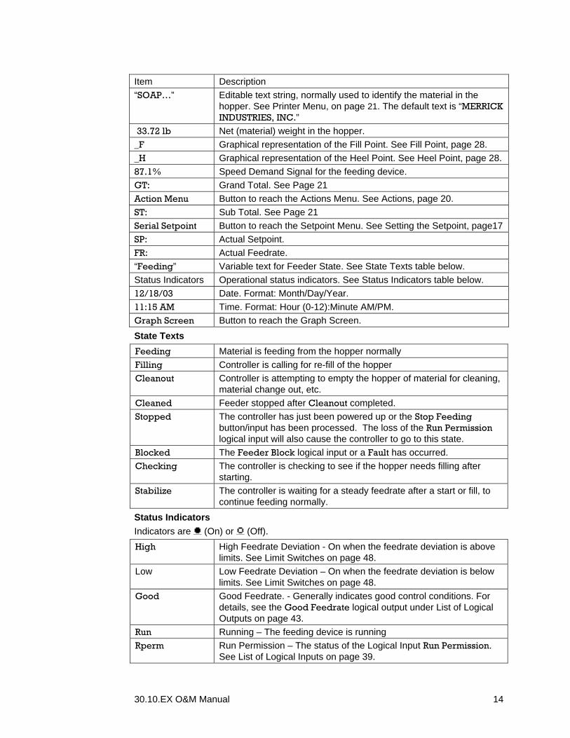
Item Description “SOAP…” Editable text string, normally used to identify the material in the
hopper. See Printer Menu, on page 21. The default text is “MERRICK INDUSTRIES, INC.”
33.72 lb Net (material) weight in the hopper. _F Graphical representation of the Fill Point. See Fill Point, page 28. _H Graphical representation of the Heel Point. See Heel Point, page 28. 87.1% Speed Demand Signal for the feeding device. GT: Grand Total. See Page 21 Action Menu Button to reach the Actions Menu. See Actions, page 20. ST: Sub Total. See Page 21 Serial Setpoint Button to reach the Setpoint Menu. See Setting the Setpoint, page17 SP: Actual Setpoint. FR: Actual Feedrate. “Feeding” Variable text for Feeder State. See State Texts table below. Status Indicators Operational status indicators. See Status Indicators table below. 12/18/03 Date. Format: Month/Day/Year. 11:15 AM Time. Format: Hour (0-12):Minute AM/PM. Graph Screen Button to reach the Graph Screen. State Texts Feeding Material is feeding from the hopper normally Filling Controller is calling for re-fill of the hopper Cleanout Controller is attempting to empty the hopper of material for cleaning,
material change out, etc. Cleaned Feeder stopped after Cleanout completed. Stopped The controller has just been powered up or the Stop Feeding
button/input has been processed. The loss of the Run Permission logical input will also cause the controller to go to this state.
Blocked The Feeder Block logical input or a Fault has occurred. Checking The controller is checking to see if the hopper needs filling after
starting. Stabilize The controller is waiting for a steady feedrate after a start or fill, to
continue feeding normally. Status Indicators Indicators are (On) or (Off). High High Feedrate Deviation - On when the feedrate deviation is above
limits. See Limit Switches on page 48. Low Low Feedrate Deviation – On when the feedrate deviation is below
limits. See Limit Switches on page 48. Good Good Feedrate. - Generally indicates good control conditions. For
details, see the Good Feedrate logical output under List of Logical Outputs on page 43.
Run Running – The feeding device is running Rperm Run Permission – The status of the Logical Input Run Permission.
See List of Logical Inputs on page 39.

30.10.EX O&M Manual 15
Block Feeder Block - This is On if the Logical Input Feeder Block is On See List of Logical Inputs on page 39.
PID PID Control - This indicator will be On when the Logical Input PID Control is ON, the controller is not in Learn Mode and there is a stable feedrate. See List of Logical Inputs on page 39.
CSG CSG Control - This indicator will be on when the Logical Input CSG Control is ON. See List of Logical Inputs on page 39.
Graph Screen A Graph screen is available to show trend information for Weight (W), Feedrate (F) and Speed Demand Signal to the feeding device (O).
Graph Screen
Item Description 04:54 PM Time. Format: Hour (0-12):Minute AP/PM. “Feeding” State Texts. See page 14. SP: Actual Setpoint. FR: Actual Feedrate. ST: Sub Total. See Page 21 OP: Speed Demand Signal for the feeding device. WT: Net (material) weight in the hopper. GT: Grand Total. See Page 21 Local Setpoint Button to reach the Setpoint Menu. See Setting the Setpoint, page17 Action Menu Button to reach the Actions Menu. See Actions, page 20. Numeric Screen Button to reach the Numeric Screen.
Numeric Screen A Numerical screen is also available to display the values in a larger typeface for easier viewing from a distance. Pushing the buttons at the left of the screen will cycle through various parameters. You also have the option of locking the selections with the Lock Num Displ logical input. See Digital I/O Mapping on page 37.
Numeric Screen

30.10.EX O&M Manual 16
Selection Description Feedrate Actual Feedrate. Total Grand Total. See Page 21 Sub Total Sub Total. See Page 21 Setpoint Actual Setpoint. Weight Net (material) weight in the hopper. Avg Wt Average Weight, after Weight Filter. See Dynamic Control on page
5. Loss Weight Loss, after Loss Calculation. See See Dynamic Control on
page 5. Date Date. Format: Month/Day/Year. Time Time. Format: Hour (0-12):Minute AM/PM. Output Speed Demand Signal for the feeding device. Deviation Setpoint minus Weight Loss. See See Dynamic Control on page 5. S Quality Quality of the Loss signal. See Method Arbitrator on page 8 Feed Factor Output required for Design Feedrate. See CSG Controller on page 7 Panel Meter Arbitrary value. An unused analog input in the MC³ can be used as a
Panel Meter. See Panel Meter on page 34. Hours Ran The accumulated time the feeder has been running. It can be reset
to zero. See Misc Data on page 66 Nothing Displayed
Warnings A Warning indicates a potential problem and calls for your attention. Any logical input or output can be configured to qualify a warning. See Digital I/O Mapping on page 37. The Warnings button is visible in any of the main screens if there is an active warning condition or there has been a warning condition that has not been acknowledged.
Feeder Screen with Warning Indicator
Pushing the Warnings button takes you to the Warnings screen. The following screen shot shows the default warnings. Your I/O configuration may be different, producing a different Warnings screen.
Warnings screen
30.10.EX O&M Manual 17
There is an active indicator to the left of the text ( = ON = OFF). There is also a “did occur” indicator to the left of the active indicator. You can acknowledge one warning at a time. Use the up and down arrow buttons to move the selection box to the Warning you want to acknowledge, and push Acknowledge. If you want to acknowledge all warnings, push the Acknwldg All button. If the Warning is still active, the Warning button will continue to be displayed on the main screens and the Warning will continue to be indicated on this screen.
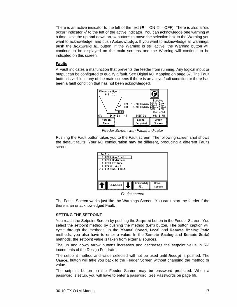
Faults A Fault indicates a malfunction that prevents the feeder from running. Any logical input or output can be configured to qualify a fault. See Digital I/O Mapping on page 37. The Fault button is visible in any of the main screens if there is an active fault condition or there has been a fault condition that has not been acknowledged.
Feeder Screen with Faults Indicator
Pushing the Fault button takes you to the Fault screen. The following screen shot shows the default faults. Your I/O configuration may be different, producing a different Faults screen.
Faults screen
The Faults Screen works just like the Warnings Screen. You can’t start the feeder if the there is an unacknowledged Fault.
SETTING THE SETPOINT You reach the Setpoint Screen by pushing the Setpoint button in the Feeder Screen. You select the setpoint method by pushing the method (Left) button. The button caption will cycle through the methods. In the Manual Speed, Local and Remote Analog Ratio methods, you also have to enter a value. In the Remote Analog and Remote Serial methods, the setpoint value is taken from external sources. The up and down arrow buttons increases and decreases the setpoint value in 5% increments of the Design Feedrate. The setpoint method and value selected will not be used until Accept is pushed. The Cancel button will take you back to the Feeder Screen without changing the method or value. The setpoint button on the Feeder Screen may be password protected. When a password is setup, you will have to enter a password. See Passwords on page 69.

30.10.EX O&M Manual 18
To prevent changes to the setpoint method, you can turn the Logical Input Lock SP Method on. This disables the ability to change the Setpoint method. See List of Logical Inputs on page 39.
Manual Setpoint Method
Manual Setpoint
The Manual setpoint method allows you to directly control the Speed Demand Signal, in percent. The controller will not attempt to control the speed. This is sometimes referred to as “Volumetric Mode”. It is useful at Startup, when adjusting the Feeder Drive or when troubleshooting. There are three buttons associated with the output speed. The Snap button allows you to capture the current Speed Demand Signal, and use it as the Manual Speed Setpoint. This will allow you to make a Bumpless Transfer. You may also directly enter the output by pushing the Setpoint button and entering the value in %.
WARNING When in Manual Setpoint, you can start the feeder regardless of the status of the Run Permission Input.
WARNING When starting, the feeder will immediately fill if the weight in the hopper is below the heelpoint, even if the setpoint is 0%.
Local Setpoint Method
Local Setpoint
With this method, you enter a Feedrate Setpoint directly at the controller, in engineering units. The controller will be active. The Snap button allows you to capture the current feedrate. This will allow you to make a Bumpless Transfer. The Setpoint button allows you to directly enter the Setpoint using the numeric entry screen.
Analog Setpoint Method
Analog Setpoint

30.10.EX O&M Manual 19
With this method the Setpoint is taken from an Analog Input. For this to work, the Analog Input used has to be configured and calibrated. See Analog Input Procedure on page 57, and Analog Setpoint on page 34.
Analog Ratio Setpoint Method
Analog Ratio Setpoint
This method scales the Feedrate Setpoint as a percentage of an incoming analog input signal. The scaling of the analog input is the same as for the Remote Analog method. This allows multiple feeders to be connected to a single analog signal with each feeder assigned a particular percentage. For example, three feeders are used to provide material to a process using one analog 4 – 20 mA signal for control. The signal is routed to the three controllers in series, and the analog inputs have the same input scaling. Feeder One provides 25%, feeder Two provides 35% and feeder Three provides 40% of the blend. When the analog signal changes, all three feeders follow, maintaining the proportions between them. The Setpoint button allows you to directly enter the percentage.
Serial Setpoint Method
Serial Setpoint
The setpoint is taken from Serial Communications. NOTE: When the controller is to be used in a networked configuration, the Remote Serial
method must be selected. The rules and format of the data exchange is described in separate publications.
Forced Serial Setpoint In networked applications, the Force Serial SP logical input can be used to unconditionally use the serial setpoint method as long as the outputs Ser Comm Lost and DF1 Comm Lost outputs both are Off. In these cases, the Change Setpoint screen will look like this

30.10.EX O&M Manual 20
Fallback Setpoint
The setpoint method and value you set here will be used only if communication fails, as a fallback.
ACTIONS Pushing the Action Menu button in any of the main screens takes you to the Action Selection menu. This is where you start and stop the feeder and perform maintenance tasks.
Action Menu
This is what the Action Menu looks like when the feeder is stopped and the logical input Run Permission is off.
Feeder Start and Stop buttons The top row in the Action Menu is used for locally starting and stopping the feeder. The buttons are context sensitive, meaning that the available buttons and their caption changes with the feeder state. See Feeder States on page 8. There are also logical inputs to remotely perform these functions. See List of Logical Inputs on page 39. Feeder State
Button 1 Button 2 Button 3 Button 4 Notes
Blocked Stopped Start
Feeding Start
Cleanout Note 1
Feeding Stop Feeding
Start Filling
Start Cleanout
Stabilize Stop Feeding
Start Filling
Start Cleanout
Filling Stop Feeding
Stop Filling
Start Cleanout
Cleanout Start Feeding
Stop Feeding
Note 2
Cleaned Start Feeding
Stop Feeding
Start Cleanout
Note 3, 4
Note 1 If Run Permission is off, no action will be taken unless Manual Speed setpoint method is set.

30.10.EX O&M Manual 21
Note 2 Pushing Start Feeding will cause the feeder to resume normal feeding. Note 3 Pushing Stop Feeding will cause the state to change from Cleaned to Stopped. Note 4 Pushing Start Cleanout in the Cleaned state will cause the feeder to enter the
Cleanout state. If the feeder is already empty, the feeder will run for a fixed time, as set in Empty Time parameter. See page 29.
Clean Off Screen Displays the Start-up Screen for one minute. Since there are no buttons in this screen, you can safely clean the touch screen.
Reset Sub-Total Clears the Sub-Total. It may be cleared at any time. When cleared, a message Subtotal Cleared appears on the screen.
Reset G-Total Clears the Total. If you use a non-zero calibration password, you will be asked to enter it. Enter the password to clear the total or push the ESC button in the password screen to escape to the action screen without clearing the Master Total. When cleared, a message “Total Cleared” appears on the display.
Diag Menu Takes you to a menu with several diagnostic screens for troubleshooting your system. See Diagnosing Problems on page 61.
Home Screen Takes you back to the Main Screen from which you entered the Action Menu.
Calibrate Menu Takes you to the Calibrate Menu. See Calibrating Your Controller on page 51.
Printer Menu This menu allows you to edit or to print one of the four available print strings and the Feeder Screen Display String. The print strings (1>, 2>, 3>, 4>) are lines of characters that convey information to a printer for permanent record. The Feeder Screen Display (D>) string allows you to place custom text on the main screen for easier controller identification.
Pushing one of these buttons will send the selected print string to the printer. The last selected line will be the line that is printed. For example, if you have pushed the button for line 1 for a test print, line 1 is the line printed when the external print command is triggered. You can embed one or more strings into the printed line. For example, you have just edited line 1 and have embedded line 2 and 3 into line 1. When you send an external print command for line 1, lines 2 and 3 will be printed would be printed also. If the last line you test printed was line 3 then only line 3 would be printed. This selection allows editing of the strings. The string to edit is selected in the function.

30.10.EX O&M Manual 22
These allow you to move character by character in the selected print string. Pushing these buttons will allow you to rotate through the character selection screens. This is the shift button. This allows you to select uppercase or non-alphanumeric characters on the buttons. If a button has two lines displayed the upper set is selected by pushing this button (SHIFT will appear under the print string) then pushing the appropriate button. This allows you to enter specific ASCII values that are not supported with a button. Also you may enter a value for the print counter and the counter increment value. You may also enter a value for print lines to be printed at specific intervals. Setting the timed print value to zero (0) turns off the timed print function. When un-shifted this is used to place a space character in your string. When the shift is enabled, it places a NULL value at that character position, which marks the end of the character string. Any characters beyond the NULL are not printed or displayed. In the un-shifted mode this button places a linefeed character in the string. When shifted, it places a carriage return at the current character position. This button toggles through the four available print strings and the main screen text display. FF - Form feed HT - Horizontal tab

30.10.EX O&M Manual 23
PF buttons. The PF buttons embeds function codes into print string.
Button Function Description PF1 ASCII CODE
DO NOT USE. Use to enter ASCII values. PF2 Total Prints the total PF3 Sub-total Prints the subtotal PF4 Date Prints the MC³ date. PF5 Time Prints the MC³ time. PF6 Clear Sub-total Clears the Sub-total PF7 Counter Prints the value of the print counter PF8 Increment counter Increment the counter PF9 Net Weight Prints the current Net Weight
PF10 Feedrate Prints the current feedrate.
PF11 Setpoint Prints the current setpoint
PF12 Register value Prints the value of a register
PF13 Weight unit Prints the Weight units.
PF14 Feedrate unit Prints the Feedrate units.
PF15 Total unit Prints the Total units
PF16 Clear currently selected print string
L1 Embed Line 1 Tells Print function to print line 1 when embedded in line 2, 3 or 4. Cannot be embedded in itself.
L2 Embed Line 2 Tells Print function to print line 2 when embedded in line 1, 3 or 4
L3 Embed Line 3 Tells Print function to print line 3 when embedded in line 1, 2 or 4.
L4 Embed Line 4 Tells Print function to print line 4 when embedded in line 1, 2 or 3.
Settings Menu This is where you set up all the controller parameters. See Setting Up Your Controller, below.

30.10.EX O&M Manual 24
SETTING UP YOUR CONTROLLER Since there are many parameters to set, they are divided into categories. They are available from two setup screens. You reach the first (Settings Menu) from any Main Screen, by pushing Action Menu, Settings menu.
Settings Menu
You reach the second (Inputs & Outputs Menu), with I/O related parameters, by pushing Inputs & Outputs.
Inputs and Outputs Menu
Most values are entered via a numeric entry screen. It shows the name of the parameter, the current value, units and the minimum and maximum allowed. If there are three or more related parameters, the controller displays three at a time; otherwise it will only show one parameter. The active parameter is enclosed in a rectangle. Any button entry will act upon this value.
Typical Numeric Entry Screen
First, find the value by using the Up or Down arrow buttons to scroll to the parameter to be changed. Enter the new value for the selected parameter using the numeric buttons. The display will show the value area as they are entered. When done, push the Enter button to save. The controller will check the number you entered. If the number is within the minimum and maximum values, a message will appear under the parameter list:
Parameter Accepted
If the value is not within the limits, the following message will appear:

30.10.EX O&M Manual 25
Value is Out of Range
SETTINGS MENU ITEMS
Select Units Use the Up or Down arrow buttons to scroll through the list of units until the desired combination appears in the center box, then push the Settings Menu button.
Select Units Menu
The following unit combinations are available Weight Total Feedrate lb lb lb/min lb lb lb/h lb TN lb/min lb TN lb/h lb TN TN/h TN TN TN/h kg kg g/s kg kg g/min kg kg kg/min kg kg kg/h kg t kg/min kg t kg/h kg t t/h t t t/h
NOTE: It may be necessary, after selecting the units, to update the decimal point selection values. See Page 25. Even if no changes to the decimal points are necessary, you should at least look at each decimal point setting.
Set Dec Pts Internally, the MC³ Controller uses floating-point numbers. Any changes to the decimal point settings affect only the display of the values. It is a good idea to set the number of decimal places so that you get 3 or 4 digit representation of the value. The minimum number of decimal places is 0 and the maximum is 4.
Design Capacities These parameters are the design values relating to the maximum useful weight of material in the hopper and the maximum feedrate that the feeder can obtain. The Design Weight is important, because it is used for automatically setting the fill and heel points and for scaling the Weight analog output.

30.10.EX O&M Manual 26
The Design Feedrate is important for the CSG performance. This value should be set to the maximum obtainable feedrate when the feeding device s running at full speed. Parameter Min Max Design Weight 1 30000 Design Feedrate 0.01 30000
Control Settings The MC³ Controller uses a PID (Proportional, Integral, Derivative) as one of its control algorithms, if the PID Control logical input is ON. Another algorithm, CSG (Control Step Gravimetric) is used if the CSG control logical input is ON. See List of Logical Inputs, on page 39. If both are on, a combination of the two is used. See See Dynamic Control on page 5. To tune the algorithms to a particular feeder, changes can be made to these parameters. It is possible let the controller adjust the Gain, Integral, Derivative, Average Slots and Loss Slots automatically. See the “Autotune” input in List of Logical Inputs on page 39. When the MC³ is in control, it is the MC³’s job to keep the feedrate at the setpoint. This is accomplished by minimizing the deviation between the setpoint and the feedrate. The PID algorithm uses the deviation to adjust the Speed Demand Signal. The CSG algorithm uses the Feed Factor. There are as many ways to tune the PID parameters as there are control engineers. We recommend you use whatever tuning method you are most familiar with.
Gain This is the PID closed loop gain, expressed in %. The settings affect all three PID controller components (Proportional, Integral and Derivative). Too much gain can cause the feeder to oscillate. Too little gain gives you sluggish control. A good starting point is a setting of 55% of the feedfactor. The feedfactor for a running feeder can be found in the Numeric Screen. See Numeric Screen on page 15. If you don’t know the feedfactor, assume it is 100%, and use a Gain Setting of 55%.
Integral The PID integral component uses the accumulated (integrated) deviation over time to adjust the feeding device speed. The Integral parameter, expressed in 1/sec, determines how fast the accumulation takes place. The Integral function will, over time, make the deviation go to zero, assuming that everything else is in steady state. A good starting point is to set the parameter according to this formula:
SampleTimetsAverageSlo5.0Integral⋅
=
See Average Slots on page 27 and Sample Rate on page 32.
Derivative The PID derivative component uses the trend of the deviation to adjust the feeding device speed. The derivative parameter, expressed in seconds, determines the sensitivity to trend changes. The Derivative function will react early to changes. A good starting point is to set the parameter according to this formula:
SampleTimetsAverageSlo03.0Derivative ⋅⋅=
SCR Accel %/s and SCR Decel %/s These two parameters provide limitations on the rate of change of the Speed Demand Signal, expressed in percent per second. The purpose is to avoid damage to the motor drive circuit, motor, and drive mechanism. Default is 200%/s, meaning that the output can change 100% in 0.5 seconds. Lowering this parameter makes the output move slower. If

30.10.EX O&M Manual 27
the drive is equipped with ramp limiting, it is better to keep this parameter at default and use the drive limitations instead.
Average Slots When the feeder is running, the weight may fluctuate, due to the effect of the feeding device, agitator or general noise. An averaging weight filter is in place to suppress this noise. This parameter determines how many weight samples are used in the averaging calculations. Generally, the longer the discharge time, the higher the number of samples or “slots”. A typical setting is
50SampleTimeeTimeargDischtsAverageSlo
⋅=
The Discharge Time must be calculated in seconds, using the Fill Point, Heel point and Design feedrate. If the Design Feedrate is expressed in kg/h or lb/h, the Discharge Time is
( )rateDesignFeed
3600intHeelPointFillPoeTimeargDisch ⋅−=
If the Design Feedrate is expressed in kg/min or lb/min, the Discharge Time is ( )
rateDesignFeed60intHeelPointFillPoeTimeargDisch ⋅−
=
The permitted range is 1 to 500. There is also an upper limit, which may be lower than 500, based on the fact that the delay in the average value must be less than 10% of the Discharge Time.
Loss Slots This parameter determines how many samples are used to determine the weigh loss, which is used to calculate the feedrate. It is normally set to the same value as the Average Slots. The same limits apply.
Max Fdr Span, Fdr Samples This is how much the Feedrate (weight loss) may change over the set Fdr Samples, for the feedrate to be considered stable. The default is 2% of the design feedrate. It can be increased or decreased, depending on what kind of control is most desirable. Increasing the value also increases the Signal Quality. See Method Arbitrator on page 8. The controller will act faster. When running both the PID and CSG control, the PID will be favored. Decreasing the value decreases the Signal Quality. The system will be less sensitive to disturbances. The controller will act slower, and favor the CSG.
Min Cred FR The Minimum Credible Feedrate is the smallest feedrate considered by the CSG control Algorithm. It is used to avoid a situation where the CSG attempts to adjust the Feedfactor upwards when the feeding device is malfunctioning or the material has bridged in the hopper. The default is 2% of the design feedrate. Set this value to the lowest feedrate you will ever use.
CSG Timeout When the weight loss is unstable, that is, not within the Max Fdr Span parameter for Fdr Samples number of samples, the feedrate indication is based on inferred values, such as Feed Factor and Speed Demand Signal. When feedrate stability resumes, the feedrate indication is again based on the weight loss. The CSG Timeout limits the time inferred values are used. When timed out, weight loss is used regardless of feedrate stability. The parameter is set by default based on many things. See Start Learning (page 58).
30.10.EX O&M Manual 28
Feed Factor The CSG controller uses this parameter to set the Speed Demand Signal, based on the Setpoint. It is also updated whenever the feedrate is stable. You can change the Feed Factor manually if needed, but it will update automatically as soon as stable feedrate conditions occur.
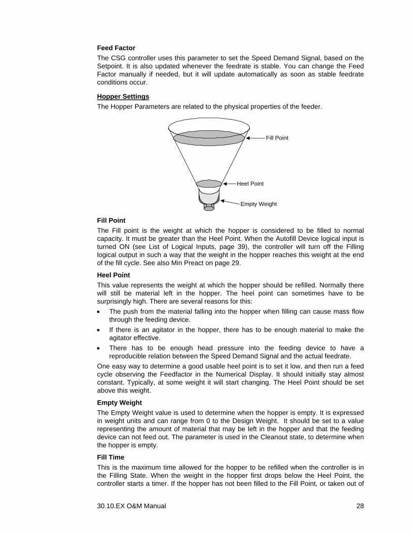
Hopper Settings The Hopper Parameters are related to the physical properties of the feeder.
Fill Point
Heel Point
Empty Weight
Fill Point The Fill point is the weight at which the hopper is considered to be filled to normal capacity. It must be greater than the Heel Point. When the Autofill Device logical input is turned ON (see List of Logical Inputs, page 39), the controller will turn off the Filling logical output in such a way that the weight in the hopper reaches this weight at the end of the fill cycle. See also Min Preact on page 29.
Heel Point This value represents the weight at which the hopper should be refilled. Normally there will still be material left in the hopper. The heel point can sometimes have to be surprisingly high. There are several reasons for this: • The push from the material falling into the hopper when filling can cause mass flow
through the feeding device. • If there is an agitator in the hopper, there has to be enough material to make the
agitator effective. • There has to be enough head pressure into the feeding device to have a
reproducible relation between the Speed Demand Signal and the actual feedrate. One easy way to determine a good usable heel point is to set it low, and then run a feed cycle observing the Feedfactor in the Numerical Display. It should initially stay almost constant. Typically, at some weight it will start changing. The Heel Point should be set above this weight.
Empty Weight The Empty Weight value is used to determine when the hopper is empty. It is expressed in weight units and can range from 0 to the Design Weight. It should be set to a value representing the amount of material that may be left in the hopper and that the feeding device can not feed out. The parameter is used in the Cleanout state, to determine when the hopper is empty.
Fill Time This is the maximum time allowed for the hopper to be refilled when the controller is in the Filling State. When the weight in the hopper first drops below the Heel Point, the controller starts a timer. If the hopper has not been filled to the Fill Point, or taken out of

30.10.EX O&M Manual 29
the Filling State manually, a Logical Output Slow Fill will turn on. This output can be set to qualify a Warning or a Fault informing the operator that the material is slow in filling the hopper. The controller remains in the Filling state even if the fill time exceeds this limit. Normally, the feedrate indication during fill is based on inferred values, since the weight loss is negative during fill. Then Slow Fill is On however, the actual weight loss is used for feedrate indication.
Weight
Fill Time
Start of Fill(Heel Point)
Fill Point
Clean Time In the Cleanout state, the feeder will run until the empty weight is reached. If the empty weight is not reached within Clean Time, the logical output “Slow Cleanout” is turned on. This value is expressed in seconds and can range from 0 to 6000 seconds (100 minutes).
Start of Cleanout
Empty Weight
Empty TimeCleanout Time
Weight
Empty Time This is an extra time that the feeder will run the feeding device after the empty weight has been reached during cleanout. When the weight in the hopper drops below the Empty Weight, the controller starts a timer. When the Empty Time is reached, the controller turns off the Drive Enable logical output, and zeroes the Speed Demand Signal.
Gate Time This parameter is set to the time it takes for the fill gate above the hopper to close and material to finish falling and stabilizing in the hopper. The purpose is to avoid a situation where the control algorithms are engaged too early after a fill. If the logical input “Fill Gate Closd” is used with a fill gate limit switch, it has to indicate “Closed” within this time. If the input fails to turn on within this time, the logical output “Fill Device Err” goes ON. It can be used to qualify a Warning.
Low Cutoff Wt This value is added to Heel Point and is used to limit the total Preact value. It keeps the fill turn-off weight from drop below the heel point.
Min Preact The Preact is a weight value used to turn off the logical output “Filling” before the fill point is reached. The purpose is to try to hit the fill point exactly. It is updated every fill cycle. This parameter is the Preact minimum limit. This parameter and the Maximum Preact parameter are the limits allowed when the controller adjusts the Preact. If you set Maximum Preact and Minimum Preact both to Zero, the Preact mechanism is disabled.

30.10.EX O&M Manual 30
Maximum Preact This parameter is the Preact maximum limit. See Min Preact on page 29 for more information on Preact.
Stability Settings The parameters are used to set stability criteria for weight. They are used in calibration procedures. For the weight to be considered stable, the weight indication must stay within the Stable Span for a certain number of weigh samples (Stable Sampls). In calibration procedures, the controller will wait for stability a limited time (Stable Time).
Stable Time This is maximum time the calibration Procedures will wait for weight stability. For noisy environments, narrow Stable Spans or many Stable Samples, increase this time from its default, which is 10 s.
Stable Span This is how much the weight indication may change over the set stable samples, for the weight to be considered stable. Default is 0.2 % of the design weight. If possible, reduce this value to get better calibration accuracy.
Stable Samples This is the number of consecutive weigh samples for which the weight must stay within the Stable Span, for the weight to be considered stable. Default is 3. For calibration accuracy, increase this value.
Calibrate Settings The following parameters are used for calibration. They are used or affected by calibration procedures. See Calibrating Your Controller on page 51.
Cal Weight The weight you will be using when running a Weight Procedure (page 53). Default is Design Weight. Limits are 10 to 110% of Design weight.
E-Cal Liveload This parameter is used for the Electronic Calibration procedure (page 55). IF you are going to be using Electronic calibration, you must calculate this parameter. You can not use the default value (1.5 mV/V). Limits are 0.2 to 3 mV/V. Performing an E-Cal Factor Procedure (page 56) will adjust this value.
Zero Weight This parameter represents all of the dead weight on the load cells. This may include the hopper, discharge device, motor, etc. This does not include the weight of the material. Default is 0. Normally adjusted by performing a Zeroing Procedure (page 52).
Scale Factor The Scale factor is used to calculate the weight from the counts coming out of the load cell A/D (HPAD) converter. It is normally adjusted using the Material Calibration (page 53), Weight Procedure (page 53) or Electronic Calibration (page 55) procedures. You can calculate the weight from the HPAD counts by using the following formula:
ZeroWeightrScaleFacto
HPADCountsWeight −=

30.10.EX O&M Manual 31
Quick Setup This button will setup nominal values, based on Design Weight and Feedrate. Pushing this button is a drastic action. It should only be done when initially setting up the controller, or when you are changing fundamental design parameters. After running the Quick Setup function, you should verify the parameters in the setup menus. The following parameters are affected:
Name Setting Page Weight Decimal Point
Set for three significant digit weight representation 25
Total Decimal Point 2 if the total unit is TN or t, else 0. 25 Feedrate Decimal Point
Set for three significant digit feedrate representation
25
Stable Span 0.2 % of Design Weight 30 Max Fdr Span 2 % of Design Feedrate 27 Minimum Credible Feedrate
2 % of Design Feedrate 27
High Feedrate Limit 90% of Design Feedrate 48 Low Feedrate Limit 10% of Design Feedrate 48 High Absolute Deviation Limit
10% of Design Feedrate 48
Low Absolute Deviation Limit
10% of Design Feedrate 48
High Setpoint Limit Design Feedrate 49 Low Setpoint Limit 0 49 High Weight Limit 110% of Design Weight 49 Low Weight Limit -10% of Design Weight 49 Empty Weight 0.2% of Design Weight 28 Heel Point If the value is between Empty Weight and Design
Weight no change. If not, 10% of Design Weight. 28
Fill Point If the value is between Heel Point and Design Weight no change. If not, 90% of Design Weight.
28
Gate Time 10% of the Discharge Time or 3 Sec, whichever is greater.
29
Cleanout Time Discharge Time 29 Preact Minimum -10% of Fill Point 29 Preact Maximum 50% of Fill Point 30 Low Cutoff Weight 5% of Design Weight 29 Setpoint Max Scale Value
Design Feedrate 34
Feedfactor 100% 51 High Feedfactor 200% 51 Low Feedfactor 20% 51 Feeding Sample Time
Set, based on the discharge time, according to the table in the Start Learning (page 58) section.
51
PID Gain 55% 26 PID Integral
SampleTimetsAverageSlo5.0⋅
26

30.10.EX O&M Manual 32
Name Setting Page PID Derivative SampleTimetsAverageSlo03.0 ⋅⋅ 26
Average Slots Set, based on the discharge time, to Average / Loss Slots according to the table in the Start Learning (page 58) section.
27
Loss Slots Same as Average Slots 27 Setpoint Filter Set, based on the discharge time, to twice the
value of the Average / Loss Slots according to the table in the Start Learning (page 58) section. The highest value is 100.
32
Feed Factor Dampening
Set, based on the discharge time, to the value in the table in the Start Learning (page 58) section.
50
High FF Time Set, based on the discharge time, to High FF time according to the table in the Start Learning (page 58) section.
51
CSG Timeout Set to twice the value of High FF Time 27
Sample Rate Use the Sample Rate menu to change how often the HPAD is sampling the Load Cell Signal. All other calculations regarding Feedrate Control are done right after a HPAD sample, so the timing set here will be the heartbeat of the entire controller.
There are two settings. You can adjust them by pushing the NUMERIC PARAMS button. The Feed Sample Time is used when the controller is feeding. The Fill Sample Time is used when the controller is filling the hopper. Normally, the Fill Sample time is shorter than the Feed Sample time The Learn feature will adjust the Feed Sample Time setting based on the discharge time.
Dampening & Display You can invert the screen and set display related parameters here. Some light conditions may call for using a negative contrast screen.
Setpt Slots Increase this value when a noisy analog signal is used for the Setpoint. You can see the dampened value in the Feeder Screen. The Setpoint Filter is important if you use CSG control. Since the algorithm is based on feedrate stability, the setpoint also has to be

30.10.EX O&M Manual 33
stable, at least intermittently. If there is noise on the Setpoint signal, the CSG will still try to follow it. The result may be a forever unstable feedrate. Increase the parameter until you read a stable setpoint value.
FeedRt Slots The Displayed FR is used to dampen the displayed feedrate value and the associated analog output. Increasing the value will increase the dampening. Increase the Displayed FR until you get a reasonable stable feedrate indication.
Backlite Off The fluorescent light behind the screen can be turned off if the touch screen is not used, just like a screen saver on a PC. Set the turn-off time here. A value of 0 will keep the back light on forever.
Grf Tm Incr This parameter determines how often the trend lines in the Graph Screen scrolls one pixel to the left.
Set Date and Time You can adjust the date and time settings here, in 24 hour format. Parameter Min Max Year 0 99 Month 1 12 Day 1 31 Hour 0 23 Minute 0 59 Seconds 0 59
INPUTS AND OUTPUTS MENU
Inputs and Outputs Menu
Analog Inputs Setup The analog inputs can be used for (mapped to) Analog Setpoint or Panel Meter. Two analog inputs are available when there are two PCIO boards installed. Once the inputs are mapped, you should adjust the high, low and scaling values.
30.10.EX O&M Manual 34
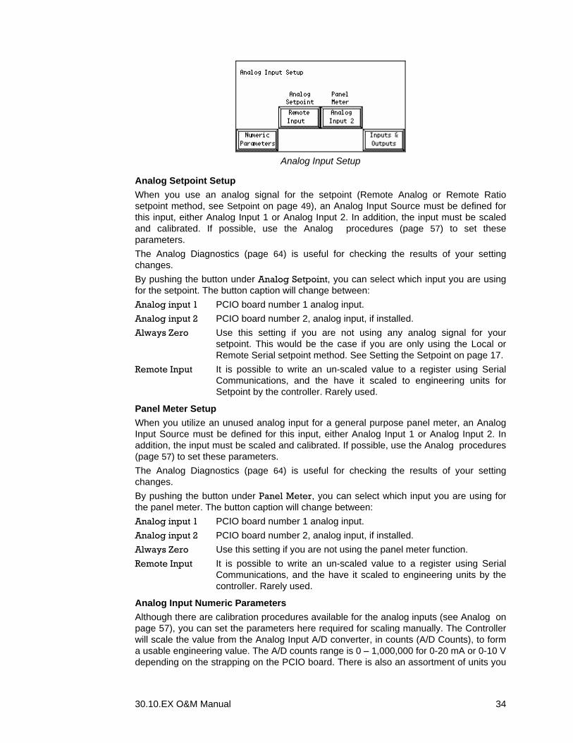
Analog Input Setup
Analog Setpoint Setup When you use an analog signal for the setpoint (Remote Analog or Remote Ratio setpoint method, see Setpoint on page 49), an Analog Input Source must be defined for this input, either Analog Input 1 or Analog Input 2. In addition, the input must be scaled and calibrated. If possible, use the Analog procedures (page 57) to set these parameters. The Analog Diagnostics (page 64) is useful for checking the results of your setting changes. By pushing the button under Analog Setpoint, you can select which input you are using for the setpoint. The button caption will change between: Analog input 1 PCIO board number 1 analog input. Analog input 2 PCIO board number 2, analog input, if installed. Always Zero Use this setting if you are not using any analog signal for your
setpoint. This would be the case if you are only using the Local or Remote Serial setpoint method. See Setting the Setpoint on page 17.
Remote Input It is possible to write an un-scaled value to a register using Serial Communications, and the have it scaled to engineering units for Setpoint by the controller. Rarely used.
Panel Meter Setup When you utilize an unused analog input for a general purpose panel meter, an Analog Input Source must be defined for this input, either Analog Input 1 or Analog Input 2. In addition, the input must be scaled and calibrated. If possible, use the Analog procedures (page 57) to set these parameters. The Analog Diagnostics (page 64) is useful for checking the results of your setting changes. By pushing the button under Panel Meter, you can select which input you are using for the panel meter. The button caption will change between: Analog input 1 PCIO board number 1 analog input. Analog input 2 PCIO board number 2, analog input, if installed. Always Zero Use this setting if you are not using the panel meter function. Remote Input It is possible to write an un-scaled value to a register using Serial
Communications, and the have it scaled to engineering units by the controller. Rarely used.
Analog Input Numeric Parameters Although there are calibration procedures available for the analog inputs (see Analog on page 57), you can set the parameters here required for scaling manually. The Controller will scale the value from the Analog Input A/D converter, in counts (A/D Counts), to form a usable engineering value. The A/D counts range is 0 – 1,000,000 for 0-20 mA or 0-10 V depending on the strapping on the PCIO board. There is also an assortment of units you

30.10.EX O&M Manual 35
can pick for the Panel Meter function. The engineering value is calculated using the following formula.
( ) MinValueMaxValueHiCnts
LoCntsDCounts/AValue +⋅−
=
There is one set of parameters for the Setpoint and one for the Panel Meter.
Panel Meter Units You can select the unit that will be displayed on the Numerical Screen for the Panel Meter function.
0 – Amps 1 – Volts 2 – Drv Amps 3 – Torque, % 4 – Temp, F 5 – Temp, C
Parameter Default Min Max SP Lo Cnts 200,000 1 1,040,000 SP Hi Cnts 1,000,000 1 1,040,000 SP Min Value 0 -Design Feedrate Design Feedrate SP Max Value Design Feedrate 0.01 150% of Design
Feedrate PMtr Lo Cnts 200,000 1 1,040,000 PMtr Hi Cnts 1,000,000 1 1,040,000 PMtr Min Value 0 -100.0 100.0 PMtr Max Value 100.0 0.01 1000000.0 PMtr Units 0 0 5
Analog Outputs Setup There are two analog outputs available per installed PCIO board, so you can have up to four analog outputs. In the Analog Outputs menu, you select what you will be using the analog outputs for. You also select between 0-20 mA (0-10 V) and 4-20mA (2 – 10 V) type outputs.
Analog Output Setup
By pushing the button under a specific Output, you can select what it will be used for The button caption will change between: SCR Output Speed Demand signal, for feeding device drive. Feedrate Actual Feedrate, with the full scale output at Design Feedrate. Weight Net Weight in the hopper, with the full scale output at Design Weight.
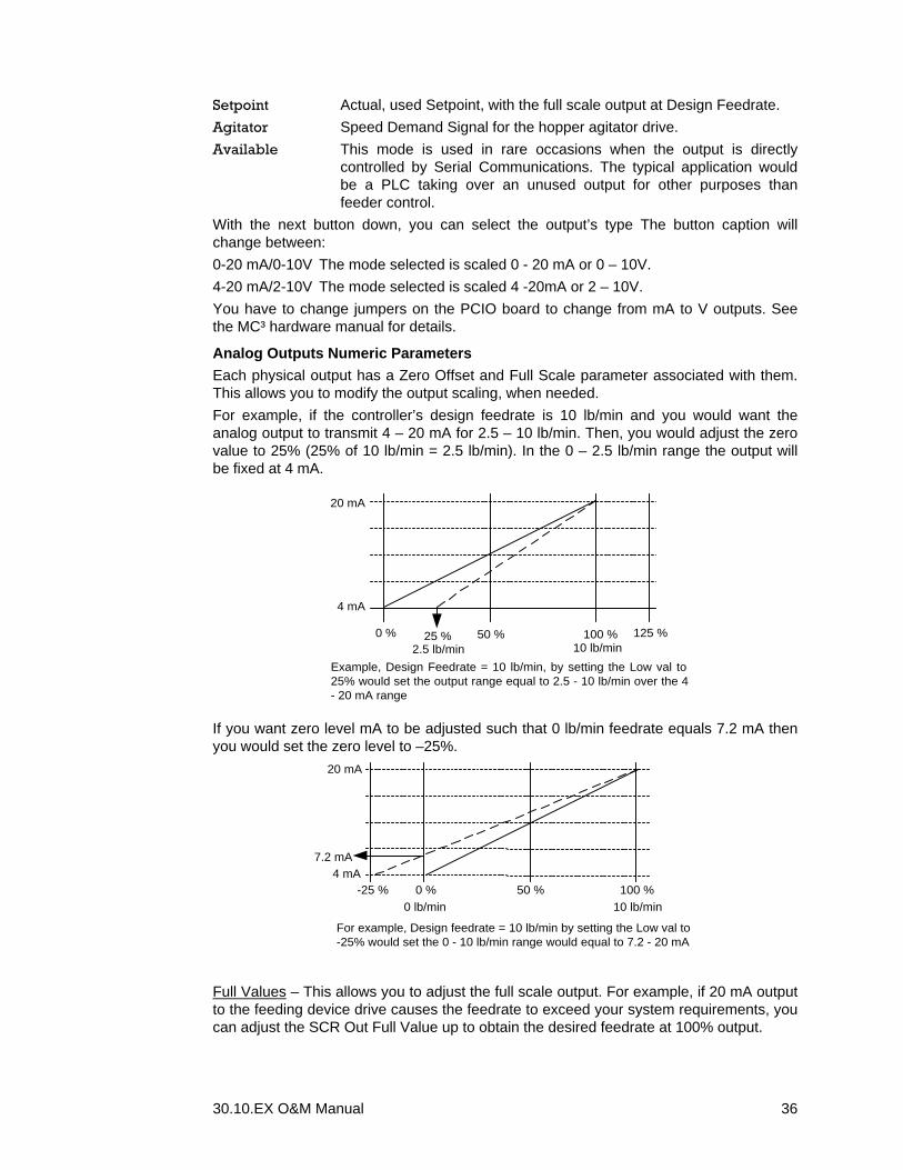
30.10.EX O&M Manual 36
Setpoint Actual, used Setpoint, with the full scale output at Design Feedrate. Agitator Speed Demand Signal for the hopper agitator drive. Available This mode is used in rare occasions when the output is directly
controlled by Serial Communications. The typical application would be a PLC taking over an unused output for other purposes than feeder control.
With the next button down, you can select the output’s type The button caption will change between: 0-20 mA/0-10V The mode selected is scaled 0 - 20 mA or 0 – 10V. 4-20 mA/2-10V The mode selected is scaled 4 -20mA or 2 – 10V. You have to change jumpers on the PCIO board to change from mA to V outputs. See the MC³ hardware manual for details.
Analog Outputs Numeric Parameters Each physical output has a Zero Offset and Full Scale parameter associated with them. This allows you to modify the output scaling, when needed. For example, if the controller’s design feedrate is 10 lb/min and you would want the analog output to transmit 4 – 20 mA for 2.5 – 10 lb/min. Then, you would adjust the zero value to 25% (25% of 10 lb/min = 2.5 lb/min). In the 0 – 2.5 lb/min range the output will be fixed at 4 mA.
4 mA
20 mA
0 % 100 %50 % 125 %
Example, Design Feedrate = 10 lb/min, by setting the Low val to25% would set the output range equal to 2.5 - 10 lb/min over the 4- 20 mA range
25 %2.5 lb/min 10 lb/min
If you want zero level mA to be adjusted such that 0 lb/min feedrate equals 7.2 mA then you would set the zero level to –25%.
4 mA
20 mA
0 % 100 %50 %-25 %
7.2 mA
For example, Design feedrate = 10 lb/min by setting the Low val to-25% would set the 0 - 10 lb/min range would equal to 7.2 - 20 mA
0 lb/min 10 lb/min
Full Values – This allows you to adjust the full scale output. For example, if 20 mA output to the feeding device drive causes the feedrate to exceed your system requirements, you can adjust the SCR Out Full Value up to obtain the desired feedrate at 100% output.

30.10.EX O&M Manual 37
For example, you want to scale the feedrate output such that 0 to 10 lb/min (with a design feedrate of 10 lb/min) to equal 4 – 16.8 mA, you would set the full value to 125%.
4 mA
20 mA
0 % 100 %50 % 125 %
16.8 mA
For example, design feedrate = 10 lb/min, by setting the Fullvalue to 125% would set the 0 - 10 lb/min range equal to 4 -16.8 mA
10 lb/min
Another example is if you want to scale the output from 0 – 7.5 lb/min over the full range (4 – 20 mA). You would then set the full value to 75%.
4 mA
20 mA
0 % 100 %50 %7.5 lb/min
For example, design feedrate = 10 lb/min, by setting the fvalue to 75% the 4 - 20 mA range would equal 0 - 7.5 lb/min.
10 lb/min
Whenever you are using non-standard output scaling, you can see the actual output, together with the underlying engineering value in Analog Diagnostics. See page 64.
Digital I/O Mapping There are many logical inputs and outputs available. Normally, you will only use a few of them for real connections. Furthermore, some logical inputs are set only once, since they in reality are used for function configuration, and should always stay On or Off. The MC³ allows you to configure the digital inputs and outputs to your system’s requirements. I/O mapping requires a layered approach. The MC³ I/O has two are two layers, a physical and a logical. The physical layer is connections to the outside world, for example relays, switches or bits in a PLC. The logical are function related, and have names like “Run Permission” and “Autotune”. The MC³ actually acts upon the logical layer. The logical input layer is mapped to the physical input layer. It is possible to have one physical input control one or more logical inputs. For example, a physical input can control both access to the custom setup menus and to the ability to accept calibration changes. The physical output layer is mapped to the logical output layer. It is possible to have one or more physical outputs mapped to one logical output. For example, you may have to start a vibrator when a “Slow Fill” condition occurs, and you also would like an indication in the control room. You can map the “Slow Fill” logical output to two different physical outputs, and then connect one to the vibrator and the other to the indicator. The Alarm property allows you to qualify a logical input or output for a Warning or Fault. When you do, the input or output name will be displayed in the Warnings (page 16) or Faults (page 17) screen.
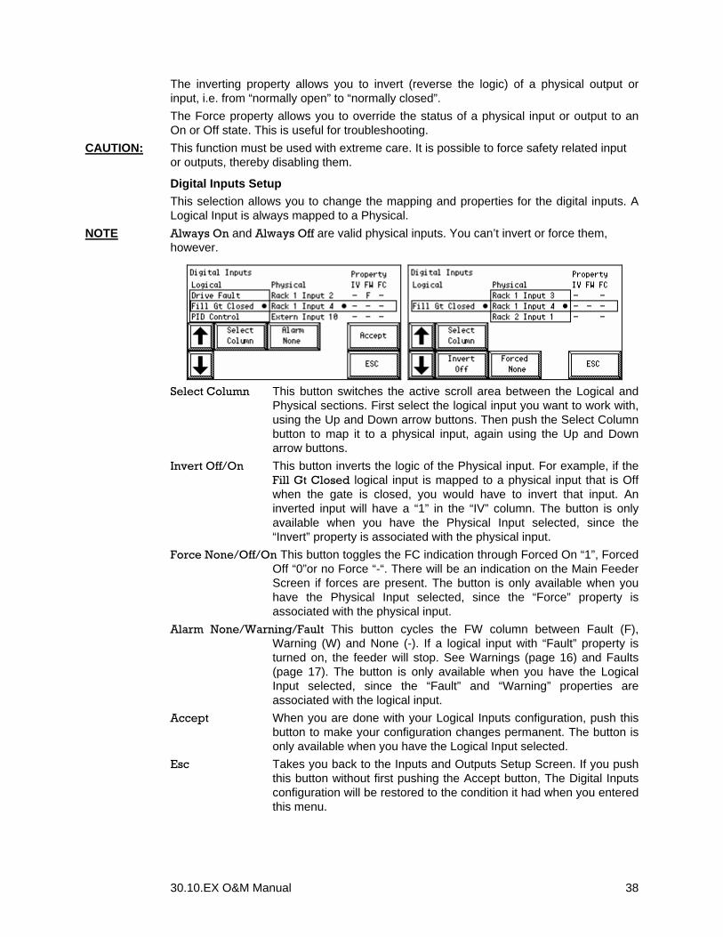
30.10.EX O&M Manual 38
The inverting property allows you to invert (reverse the logic) of a physical output or input, i.e. from “normally open” to “normally closed”. The Force property allows you to override the status of a physical input or output to an On or Off state. This is useful for troubleshooting.
CAUTION: This function must be used with extreme care. It is possible to force safety related input or outputs, thereby disabling them.
Digital Inputs Setup This selection allows you to change the mapping and properties for the digital inputs. A Logical Input is always mapped to a Physical.
NOTE Always On and Always Off are valid physical inputs. You can’t invert or force them, however.
Select Column This button switches the active scroll area between the Logical and
Physical sections. First select the logical input you want to work with, using the Up and Down arrow buttons. Then push the Select Column button to map it to a physical input, again using the Up and Down arrow buttons.
Invert Off/On This button inverts the logic of the Physical input. For example, if the Fill Gt Closed logical input is mapped to a physical input that is Off when the gate is closed, you would have to invert that input. An inverted input will have a “1” in the “IV” column. The button is only available when you have the Physical Input selected, since the “Invert” property is associated with the physical input.
Force None/Off/On This button toggles the FC indication through Forced On “1”, Forced Off “0”or no Force “-“. There will be an indication on the Main Feeder Screen if forces are present. The button is only available when you have the Physical Input selected, since the “Force” property is associated with the physical input.
Alarm None/Warning/Fault This button cycles the FW column between Fault (F), Warning (W) and None (-). If a logical input with “Fault” property is turned on, the feeder will stop. See Warnings (page 16) and Faults (page 17). The button is only available when you have the Logical Input selected, since the “Fault” and “Warning” properties are associated with the logical input.
Accept When you are done with your Logical Inputs configuration, push this button to make your configuration changes permanent. The button is only available when you have the Logical Input selected.
Esc Takes you back to the Inputs and Outputs Setup Screen. If you push this button without first pushing the Accept button, The Digital Inputs configuration will be restored to the condition it had when you entered this menu.

30.10.EX O&M Manual 39
List of Logical Inputs
Logical Input Description Feeder Block Used to unconditionally stop the feeder. When on, the Speed
Demand Signal goes to zero and the Logical Output Drive Enable goes off. The feeder status line in the Main and Trend screens will read Blocked.
Run Permission This input is used to start and stop the feeder in any automatic Setpoint Method. The feeder will run when the input is turned on. It will not start from a blocked or boot state unless the Auto Start Fdr is On or Run Permission is toggled. Toggling the input Off and then On has the same effect as pushing the Start Feeder button in the Action menu. Turning the input Off stops the feeder, and has the same effect as pushing the Stop Feeder button in the Action menu. The feeder status line in the Main and Trend screens will read “Stopped”. If the Feedrate Setpoint Method is set to “Manual Speed”, (non-automatic mode) this input is ignored.
Stop Feeder Immediately stops the feeder. Works in parallel with the Stop Feeder button in the Action Menu.
Start Feeder Starts the feeder if Run Permission is On and Feeder Block is Off. If the Manual Speed Setpoint Method is used, the Run Permission input is ignored. Works in parallel with the Start Feeder button in the Action Menu.
Stop filling Immediately Stops a fill cycle if the weight is above than the Heel Point. Works in parallel with the Stop Fill button in the Action menu.
Start filling Immediately Starts a fill cycle, if the weight is below the Fill Point. Works in parallel with the Start Fill button in the Action menu.
Start Cleanout Starts the Cleanout procedure. Useful if you want to test the feeding device when the feeder is empty, since the feeding device will run for the time set in the Clean Time parameter (page 29), without trying to fill the hopper.
Drive not Ready This drive feedback input is used to indicate that the feeding device drive is not ready to run. The state of the input is combined with other states to form the Ready Logical Output. It has no other effect, unless you make it qualify a Warning or Fault.
Drive Fault This drive feedback input is used to indicate that the feeding device drive has faulted. The state of the input is combined with other states to form the Ready Logical Output. It has no other effect, unless you make it qualify a Warning or Fault.
Fill Gt Closed This is normally connected to a limit switch on the fill gate to indicate that the fill gate is closed. See Gate Time on page 29. Map to Always On if unused.
PID Control Enables the PID control algorithm. See Dynamic Control on page 5.

30.10.EX O&M Manual 40
Logical Input Description CSG Control Enables the CSG control algorithm. See Dynamic Control on
page 5. AutoFill Gt Informs the controller that an automatic fill device (hopper gate)
is attached to automatically fill the hopper when the heel point has been reached. If the input is Off, the controller will have to be taken out of the Fill State manually, either with the Stop Fill button in the Action menu, or with the Stop Filling input. WARNING: If you have an automatically operated filling device, turning this input Off will most likely overfill your hopper.
Auto Tune Continuous auto-tuning of control parameters. This input should only be ON if the hopper is filled automatically, and the physical properties of the material and feeding device changes slowly. See Control Settings on page 26.
Use Fill Adjust When this input is on, memorized Feedfactor values are used to adjust the Feedfactor during fill. Normally, this function is not needed, and the input is mapped to Always Off. If there is a serious head pressure effect, where the weight in the hopper affects the efficiency of the feeding device, first turn both this input and Aut Fill Adjust On. Monitor the feeder performance right after fill has competed. When satisfied, turn Aut Fill Adjust Off.
Aut Fill Adjust When this input is on, the CSG control algorithm attempts to memorize the Feedfactor / Weight dependency during a normal discharge sequence. It should only be turned on if the hopper is filled automatically, and the physical properties of the material and feeding device changes slowly. Normally, this function is not needed, and the input is mapped to Always OFF. If there is a serious head pressure effect, where the weight in the hopper affects the efficiency of the feeding device, this input should be turned on. The feeder performance should be monitored closely.
Agitator Turn this input On if you want to use the controller’s agitator function.
Allow Calib Allows changes to controller calibration. When Off, you can still run the procedures, but there is no Accept button available in any calibration procedure.
Lock Num Displ Input to lock the Numerical Screen variable selections. See Numeric Screen on page 15.
AutoStartFeeder Controls the starting of the controller at power up. If Run Permission is On and Feeder Block is Off, the feeder will start immediately if is this input in ON. Otherwise, you either have to push the Start Feeder button in the Action Menu, or toggle the Run Permission input. WARNING When On, this input will typically cause the feeder to immediately fill when the controller is powered up after maintenance.
Lock SP Method Locks the Setpoint Method to the current selection. See Setting the Setpoint on page 17.
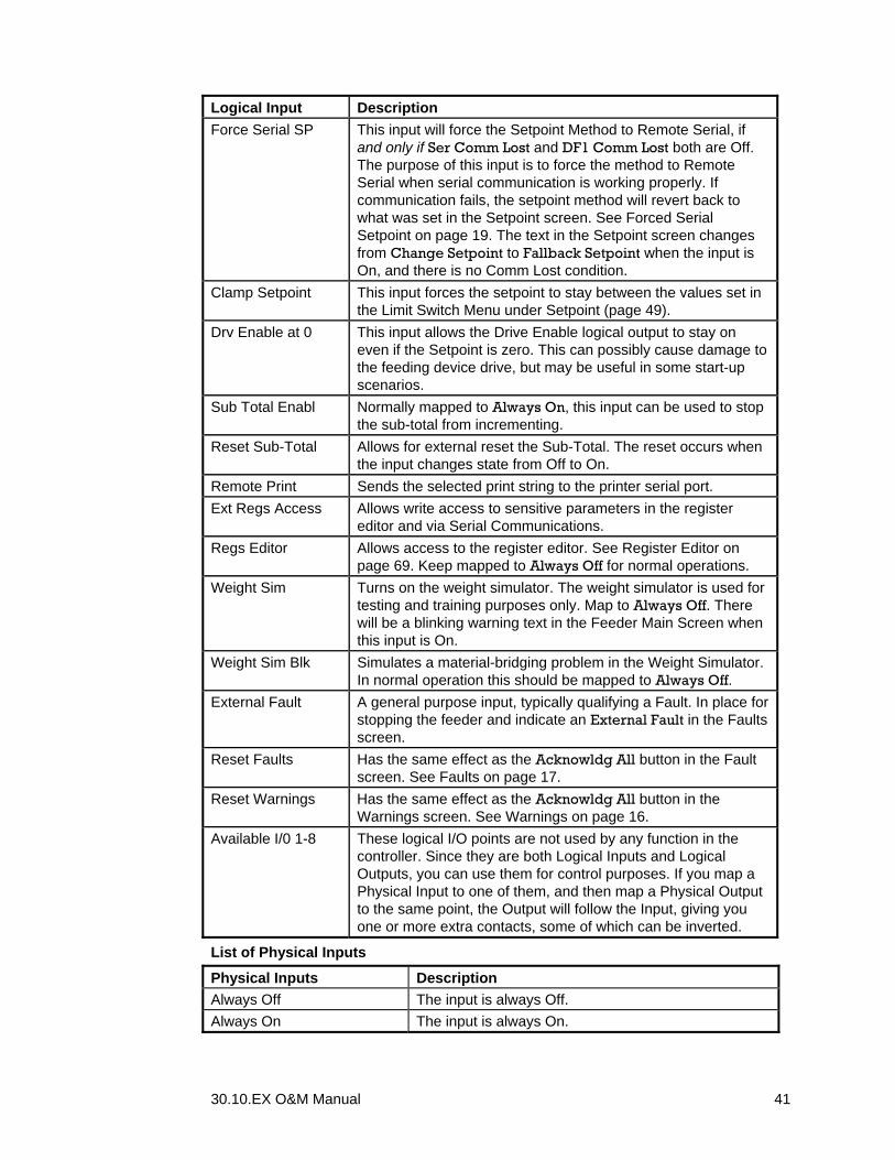
30.10.EX O&M Manual 41
Logical Input Description Force Serial SP This input will force the Setpoint Method to Remote Serial, if
and only if Ser Comm Lost and DF1 Comm Lost both are Off. The purpose of this input is to force the method to Remote Serial when serial communication is working properly. If communication fails, the setpoint method will revert back to what was set in the Setpoint screen. See Forced Serial Setpoint on page 19. The text in the Setpoint screen changes from Change Setpoint to Fallback Setpoint when the input is On, and there is no Comm Lost condition.
Clamp Setpoint This input forces the setpoint to stay between the values set in the Limit Switch Menu under Setpoint (page 49).
Drv Enable at 0 This input allows the Drive Enable logical output to stay on even if the Setpoint is zero. This can possibly cause damage to the feeding device drive, but may be useful in some start-up scenarios.
Sub Total Enabl Normally mapped to Always On, this input can be used to stop the sub-total from incrementing.
Reset Sub-Total Allows for external reset the Sub-Total. The reset occurs when the input changes state from Off to On.
Remote Print Sends the selected print string to the printer serial port. Ext Regs Access Allows write access to sensitive parameters in the register
editor and via Serial Communications. Regs Editor Allows access to the register editor. See Register Editor on
page 69. Keep mapped to Always Off for normal operations. Weight Sim Turns on the weight simulator. The weight simulator is used for
testing and training purposes only. Map to Always Off. There will be a blinking warning text in the Feeder Main Screen when this input is On.
Weight Sim Blk Simulates a material-bridging problem in the Weight Simulator. In normal operation this should be mapped to Always Off.
External Fault A general purpose input, typically qualifying a Fault. In place for stopping the feeder and indicate an External Fault in the Faults screen.
Reset Faults Has the same effect as the Acknowldg All button in the Fault screen. See Faults on page 17.
Reset Warnings Has the same effect as the Acknowldg All button in the Warnings screen. See Warnings on page 16.
Available I/0 1-8 These logical I/O points are not used by any function in the controller. Since they are both Logical Inputs and Logical Outputs, you can use them for control purposes. If you map a Physical Input to one of them, and then map a Physical Output to the same point, the Output will follow the Input, giving you one or more extra contacts, some of which can be inverted.
List of Physical Inputs
Physical Inputs Description Always Off The input is always Off. Always On The input is always On.
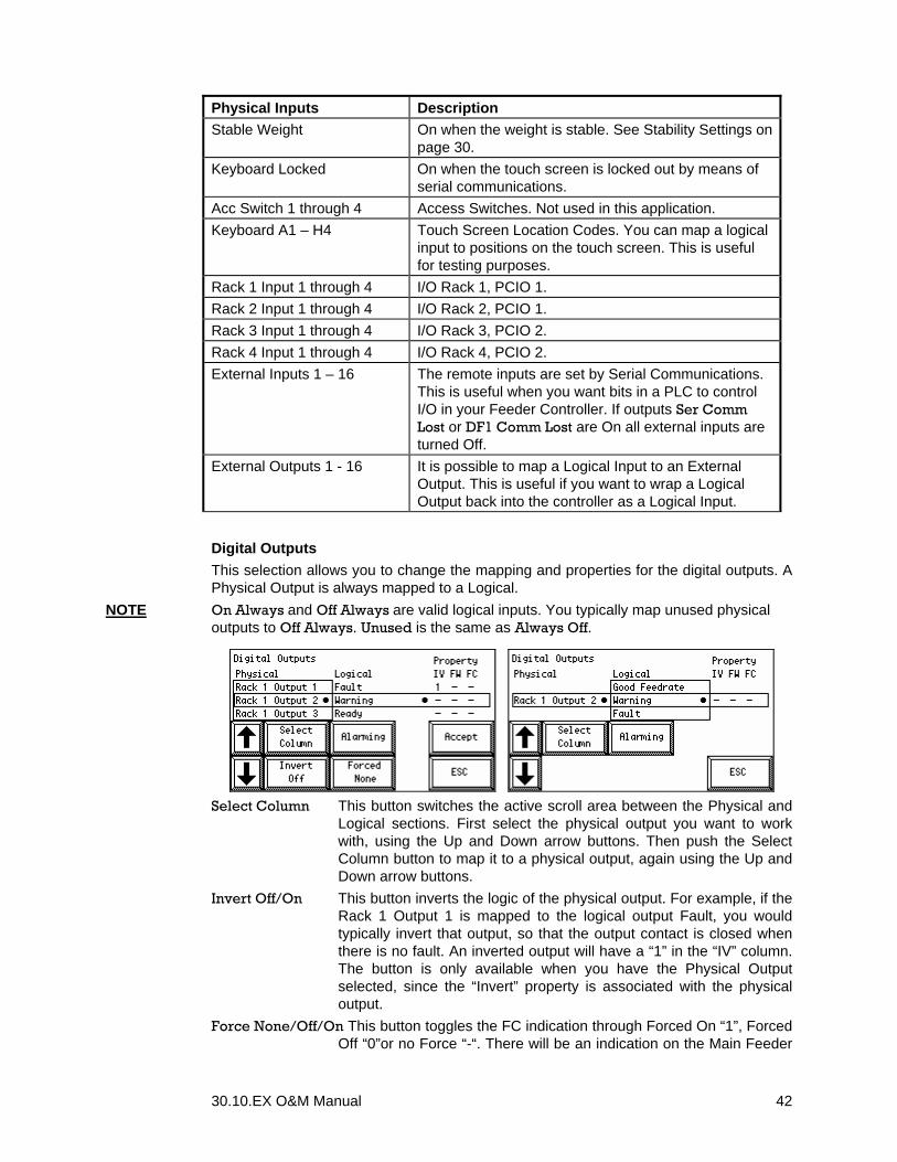
30.10.EX O&M Manual 42
Physical Inputs Description Stable Weight On when the weight is stable. See Stability Settings on
page 30. Keyboard Locked On when the touch screen is locked out by means of
serial communications. Acc Switch 1 through 4 Access Switches. Not used in this application. Keyboard A1 – H4 Touch Screen Location Codes. You can map a logical
input to positions on the touch screen. This is useful for testing purposes.
Rack 1 Input 1 through 4 I/O Rack 1, PCIO 1. Rack 2 Input 1 through 4 I/O Rack 2, PCIO 1. Rack 3 Input 1 through 4 I/O Rack 3, PCIO 2. Rack 4 Input 1 through 4 I/O Rack 4, PCIO 2. External Inputs 1 – 16 The remote inputs are set by Serial Communications.
This is useful when you want bits in a PLC to control I/O in your Feeder Controller. If outputs Ser Comm Lost or DF1 Comm Lost are On all external inputs are turned Off.
External Outputs 1 - 16 It is possible to map a Logical Input to an External Output. This is useful if you want to wrap a Logical Output back into the controller as a Logical Input.
Digital Outputs This selection allows you to change the mapping and properties for the digital outputs. A Physical Output is always mapped to a Logical.
NOTE On Always and Off Always are valid logical inputs. You typically map unused physical outputs to Off Always. Unused is the same as Always Off.
Select Column This button switches the active scroll area between the Physical and
Logical sections. First select the physical output you want to work with, using the Up and Down arrow buttons. Then push the Select Column button to map it to a physical output, again using the Up and Down arrow buttons.
Invert Off/On This button inverts the logic of the physical output. For example, if the Rack 1 Output 1 is mapped to the logical output Fault, you would typically invert that output, so that the output contact is closed when there is no fault. An inverted output will have a “1” in the “IV” column. The button is only available when you have the Physical Output selected, since the “Invert” property is associated with the physical output.
Force None/Off/On This button toggles the FC indication through Forced On “1”, Forced Off “0”or no Force “-“. There will be an indication on the Main Feeder

30.10.EX O&M Manual 43
Screen if forces are present. The button is only available when you have the Physical Output selected, since the “Force” property is associated with the physical output.
Alarming Since un-mapped logical outputs are not visible in this screen, this button takes you to another screen where you can set the Faults and Warnings properties for all logical outputs, both mapped and un-mapped.
Set the Warning and Fault properties for all Logical Outputs by
scrolling to the output with the up and down arrows and then push the Select F/W button. When you are done, push the Return button.
Accept When you are done with your Logical Outputs configuration, push this button to make your configuration changes permanent. The button is only available when you have the Logical Output column selected.
Esc Takes you back to the Inputs and Outputs Setup Screen. If you push this button without first pushing the Accept button, The Digital Outputs configuration will be restored to the condition it had when you entered this menu.
List of Logical Outputs
Logical Output Description Fdr Drv Enable Intended for enabling the feeding device drive Turns on when
the controller is running and the setpoint is greater than 0. If the Drv Enable at 0 logical input is On, the output will be On when the controller is started regardless of the setpoint.
Fill Gate Open The weigh hopper needs filling. Normally connected t a fill gate solenoid.
Weight Stable The weight value is stable, according to the Stability Settings (page 30).
Cleaning Out The feeder is in the Cleanout or Cleaned State. Cal Weights On Place calibration weights on the feeder during a Weight
Calibration procedure. Intended for automatic calibration equipment.
Agit Drv Enable Intended for enabling the agitator. There are two modes of operation: 1: The agitator runs whenever the weight in the hopper exceeds the Low Weight Limit and the Ready output is on. 2: The agitator runs whenever the Running output is on.
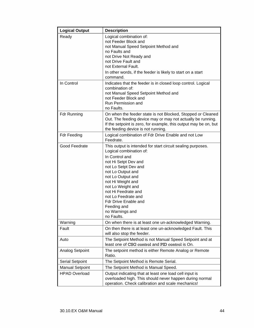
30.10.EX O&M Manual 44
Logical Output Description Ready Logical combination of:
not Feeder Block and not Manual Speed Setpoint Method and no Faults and not Drive Not Ready and not Drive Fault and not External Fault. In other words, if the feeder is likely to start on a start command.
In Control Indicates that the feeder is in closed loop control. Logical combination of: not Manual Speed Setpoint Method and not Feeder Block and Run Permission and no Faults.
Fdr Running On when the feeder state is not Blocked, Stopped or Cleaned Out. The feeding device may or may not actually be running. If the setpoint is zero, for example, this output may be on, but the feeding device is not running.
Fdr Feeding Logical combination of Fdr Drive Enable and not Low Feedrate.
Good Feedrate This output is intended for start circuit sealing purposes. Logical combination of: In Control and not Hi Setpt Dev and not Lo Setpt Dev and not Lo Output and not Lo Output and not Hi Weight and not Lo Weight and not Hi Feedrate and not Lo Feedrate and Fdr Drive Enable and Feeding and no Warnings and no Faults.
Warning On when there is at least one un-acknowledged Warning. Fault On then there is at least one un-acknowledged Fault. This
will also stop the feeder. Auto The Setpoint Method is not Manual Speed Setpoint and at
least one of CSG control and PID control is On. Analog Setpoint The setpoint method is either Remote Analog or Remote
Ratio. Serial Setpoint The Setpoint Method is Remote Serial. Manual Setpoint The Setpoint Method is Manual Speed. HPAD Overload Output indicating that at least one load cell input is
overloaded high. This should never happen during normal operation. Check calibration and scale mechanics!

30.10.EX O&M Manual 45
Logical Output Description HPAD Underload Output indicating that at least one load cell input is
overloaded low. This should never happen during normal operation. Check calibration and scale mechanics!
Hi Setpt Dev Output indicating that the difference between the feedrate and the setpoint has been above set limits for a set time. See the deviation limits under Feedrate on page 48. The output only goes On if the feeder is running.
Lo Setpt Dev Output indicating that the difference between the feedrate and the setpoint has been below set limits for a set time. See the deviation limits under Feedrate on page 48. The output only goes On if the feeder is running.
Hi Feedrate Output indicating that the feedrate has exceeded a set limit for a set time. See the feedrate limits under Feedrate on page 48. The output only goes On if the feeder is running.
Lo Feedrate Output indicating that the feedrate has been below a set limit for a set time. See the feedrate limits under Feedrate on page 48. The output only goes On if the feeder is running.
Hi Setpoint Output indicating that the setpoint is above the set limits for a set time. See Setpoint on page 49. The output only goes On if the feeder is running.
Lo Setpoint Output indicating that the setpoint is below the set limits for a set time. See Setpoint on page 49. The output only goes On if the feeder is running.
Hi Output Output indicating that the speed demand signal would exceed the limit set in Output (page 49). The output goes off if the feeder stops.
Lo Output Output indicating that the speed demand signal would lag the limit set in Output (page 49). The output goes off if the feeder stops.
Hi Weight Output indicating that the weight has exceeded a set limit for a set time. See Weight on page 49. Output is active regardless of feeder state.
Lo Weight Output indicating that the weight has been below a set limit for a set time. See Weight on page 49. Output is active regardless of feeder state.
Hi Feedfactor Output indicating that the Feedfactor has reached the allowed upper limit, which normally is 200%. The meaning of this indication is that the feeding device in inefficient. The output goes off if the feeder stops.
Lo Feedfactor Output indicating that the Feedfactor has reached the allowed lower limit, which is normally 20%. The most probable cause is that mass flow is occurring through the feeding device or material is leaking out of the hopper. The output goes off if the feeder stops.
In Menu System Output indicating that someone is working in the controller menus. Intended for tampering indication.
Unstable Fdrate An entire discharge cycle has passed without ever reaching a stable feedrate. Re-tune the controller! Increase MaxFdrSpan or increase Average Slots and Loss Slots.
Touchpad Locked The touch screen is locked out by communications

30.10.EX O&M Manual 46
Logical Output Description Slow fill The time used to fill the hopper has exceeded the allowed
time. See Fill Time on page 28. Slow cleanout The time needed to reach the Empty Weight during Cleanout
has exceeded the allowed time. See Clean Time on page 29. Fill Gt not Cls The Fill gate has not closed within the Gate Time (page 29). DF1 Comm Lost The time from the last good DF1 telegram received on COM2
has expired. See the DF1 Timeout parameter under Comm 2 Numeric on page 48.
Ser Comm Lost Output indicating that serial communication on COM1 (ScaleNet or Modbus) has timed out. This is also referred to as a “Comm Timeout” condition. See Comm 1 Numeric on page 48.
Power Fail Power was lost to the controller and was then re-applied. This output is turned On at power on, and then immediately Off. If you want to be informed of power cycles, qualify this output for a Warning.
HPAD Failure At least one of the HPAD boards fails to produce reliable data. Controller needs service.
LCD Failure An Error has occurred in the LCD display. Controller needs service.
Diff in HPADs Output indicating that the difference in weight sensed between the two HPAD’s exceed a set limit. This is only applicable when you have two HPAD boards installed. See Allowed Difference on page 69.
Register Access Not used in this application. AuxIO 1-8 Delayed These are delayed outputs available for Available IO points
1-8. Access to the time delays parameters is in the register editor only.
On Always Output is always ON (closed). Off Always Output is always OFF (open). Available I/0 1-8 These logical I/O points are not used by any function in the
controller. Since they are both Logical Inputs and Logical Outputs, you can use them for control purposes. If you map a Physical Input to one of them, and then map a Physical Output to the same point, the Output will follow the Input, giving you one or more extra contacts, some of which can be inverted.
List of Physical Outputs
Physical Output Description Rack 1 Output 1 through 8 I/O Rack 1, PCIO 1. Rack 2 Output 1 through 8 I/O Rack 2, PCIO 1. Rack 3 Output 1 through 8 I/O Rack 3, PCIO 2. Rack 4 Output 1 through 8 I/O Rack 4, PCIO 2. Remote Output 1 - 16 The remote outputs are red by Serial
Communications. This is useful when you want bits in a PLC to reflect logical outputs in your Feeder Controller.
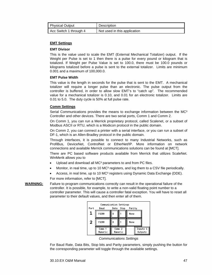
30.10.EX O&M Manual 47
Physical Output Description Acc Switch 1 through 4 Not used in this application
EMT Settings
EMT Divisor This is the value used to scale the EMT (External Mechanical Totalizer) output. If the Weight per Pulse is set to 1 then there is a pulse for every pound or kilogram that is totalized. If Weight per Pulse Value is set to 100.0, there must be 100.0 pounds or kilograms totalized before a pulse is sent to the external totalizer. Limits are minimum 0.001 and a maximum of 100,000.0.
EMT Pulse Width This value is the length in seconds for the pulse that is sent to the EMT. A mechanical totalizer will require a longer pulse than an electronic. The pulse output from the controller is buffered, in order to allow slow EMT’s to “catch up”. The recommended value for a mechanical totalizer is 0.10, and 0.01 for an electronic totalizer. Limits are 0.01 to 5.0. The duty cycle is 50% at full pulse rate.
Comm Settings Serial Communications provides the means to exchange information between the MC³ Controller and other devices. There are two serial ports, Comm 1 and Comm 2. On Comm 1, you can run a Merrick proprietary protocol, called Scalenet, or a subset of Modbus ASCII or RTU, which is a Modicon protocol in the public domain. On Comm 2, you can connect a printer with a serial interface, or you can run a subset of DF-1, which is an Allen-Bradley protocol in the public domain. Through interfaces, it is possible to connect to many Industrial Networks, such as ProfiBus, DeviceNet, ControlNet or EtherNet/IP. More information on network connections and available Merrick communications solutions can be found at [MCT]. There are PC based software products available from Merrick that utilizes ScaleNet. WinMerik allows you to • Upload and download all MC³ parameters to and from PC files. • Monitor, in real time, up to 10 MC³ registers, and log them to a CSV file periodically. • Access, in real time, up to 10 MC³ registers using Dynamic Data Exchange (DDE). For more information, refer to [MCT].
WARNING: Failure to program communications correctly can result in the operational failure of the controller. It is possible, for example, to write a non-valid floating point number to a controller parameter. This will cause a controller fatal exception. You will have to reset all parameter to their default values, and then enter all of them.
Communications Settings
For Baud Rate, Data Bits, Stop bits and Parity parameters, simply pushing the button for the corresponding parameter will toggle through the available settings.

30.10.EX O&M Manual 48
Comm 1 Numeric For details, refer to Modbus and Scalenet documentation at [MCT]. Param Meaning Controller # Controller Number for ScaleNet, Node Number for Modbus Start Char ASCII code for ScaleNet telegram start character. Default 10 (LF) End Char ASCII code for ScaleNet telegram end character. Default 13 (CR) Comm Timeout Timer for Ser Com Lost output. A value of 0 means “forever” Com Protocol Set to 0 for ScaleNet
Set to 1 for Modbus ASCII Set to 2 for Modbus RTU
Write Prot Write protection bits for Common Interface Table (CIT) variables. Decimal representation. See [MCT].
Word Order Floating point representation word order bit pattern for CIT Int/Frac FP Integer Fraction floating point representation bit pattern for CIT Tag Reg 1 – 5 MC³ register number tagged. See [MCT]. Comm 2 Numeric For details, refer to DF-1 documentation at [MCT]. Param Meaning Prtr/0 DF1/1 Set to 0 for Comm2 to be used for a serial printer
Set to 1 for Comm2 to be used for DF-1 communications DF-1 Timeout Timer for DF-1 Comm Lost output. A value of 0 means “forever” DF-1 uses BCC Set to 0 for CRC error check
Set to 1 for BCC error check. Write Prot Write protection bits for Common Interface Table (CIT) variables.
Decimal representation. See [MCT]. Word Order Floating point representation word order bit pattern for CIT Int/Frac FP Integer Fraction floating point representation bit pattern for CIT Tag Reg 1 – 5 MC³ register number tagged. See [MCT].
Limit Switches
There are several programmable limit switches. This is where you set the limits and delays associated with them. Main screen indicators and logical outputs are directly affected. See Digital I/O Mapping on page 37 and Status Indicators on page 14.
Feedrate Limits This button allows you to set the upper and lower limits for the feedrate and feedrate deviation logical outputs. Hi and Lo FeedRate are absolute limits, in engineering units, that control the Hi Feedrate and Lo Feedrate logical outputs. The Hi/Lo Setpt Dev logical outputs are used to signal a sustained difference between the Setpoint and Feedrate. They are controlled by combining the Hi/Lo Rel Dev and Hi/Lo Rate Dev conditions. The
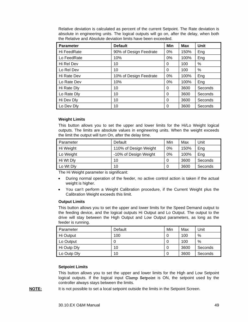
30.10.EX O&M Manual 49
Relative deviation is calculated as percent of the current Setpoint. The Rate deviation is absolute in engineering units. The logical outputs will go on, after the delay, when both the Relative and Absolute deviation limits have been exceeded.
Parameter Default Min Max Unit Hi FeedRate 90% of Design Feedrate 0% 150% Eng Lo FeedRate 10% 0% 100% Eng Hi Rel Dev 10 0 100 % Lo Rel Dev 10 0 100 % Hi Rate Dev 10% of Design Feedrate 0% 100% Eng Lo Rate Dev 10% 0% 100% Eng Hi Rate Dly 10 0 3600 Seconds Lo Rate Dly 10 0 3600 Seconds Hi Dev Dly 10 0 3600 Seconds Lo Dev Dly 10 0 3600 Seconds
Weight Limits This button allows you to set the upper and lower limits for the Hi/Lo Weight logical outputs. The limits are absolute values in engineering units. When the weight exceeds the limit the output will turn On, after the delay time.
Parameter Default Min Max Unit Hi Weight 110% of Design Weight 0% 150% Eng Lo Weight -10% of Design Weight 0% 100% Eng Hi Wt Dly 10 0 3600 Seconds Lo Wt Dly 10 0 3600 Seconds The Hi Weight parameter is significant: • During normal operation of the feeder, no active control action is taken if the actual
weight is higher. • You can’t perform a Weight Calibration procedure, if the Current Weight plus the
Calibration Weight exceeds this limit.
Output Limits This button allows you to set the upper and lower limits for the Speed Demand output to the feeding device, and the logical outputs Hi Output and Lo Output. The output to the drive will stay between the High Output and Low Output parameters, as long as the feeder is running.
Parameter Default Min Max Unit Hi Output 100 0 100 % Lo Output 0 0 100 % Hi Outp Dly 10 0 3600 Seconds Lo Outp Dly 10 0 3600 Seconds
Setpoint Limits This button allows you to set the upper and lower limits for the High and Low Setpoint logical outputs. If the logical input Clamp Setpoint is ON, the setpoint used by the controller always stays between the limits.
NOTE: It is not possible to set a local setpoint outside the limits in the Setpoint Screen.

30.10.EX O&M Manual 50
Parameter Default Min Max Unit Hi Setpoint 100 % of Design Feedrate 0 150 Eng Lo Setpoint 0 % of Design Feedrate 0 100 Eng Hi Sp Dly 10 0 3600 Seconds Lo Sp Dly 10 0 3600 Seconds
Feed Factor Limits You set limits and some operational parameters for the CSG control algorithm here. Parameters are Max Feedfact Upper limit for the Feedfactor. Default is 200%. The Hi Feedfactor
output goes on immediately if this limit is reached. Use the output as an indicator of feeding problems, such as material bridging or feeding device clogging up. Set the limit to 10 % above the peak Feedfactor observed during normal operation.
Min Feedfact Lower limit for the Feedfactor. Default is 20%. The Lo Feedfactor output goes on immediately if this limit is reached. Use the output as an indicator of flooding or leakage problems, such as material free-flowing through the feeding device or material leakage. Set the limit to 10 % below the lowest Feedfactor observed during normal operation.
HiFF Start T Upper Feedfactor Start Time. The default is dependant of the discharge time. This parameter is used when the Use Fill Adjust and/or Auto Fill Adjust inputs are On. If there is a significant head pressure effect on the feeder device, such that the efficiency is depending on the weight, there will be a feedrate deviation every time the cycle exits out of fill. In these cases, the MC³ can learn the typical Feedfactor right after (Upper Feedfactor) and right before (Lower Feedfactor) the fill sequence. These parameters will then be used to adjust the Feedfactor during fill. This parameter determines how long the MC³ will wait after the fill cycle has completed before the Upper Feedfactor is sampled.
HiFF Stop % Upper Feedfactor Stop %. Default is 80%. The Upper Feedfactor will be sampled from the end of the HiFF Start T until the weight is at this percentage of the weight cycle span. The weight cycle span is defined as the difference between the Fill and Heel point.
Loff Start % Lower Feedfactor Stop %. Default is 20%. The Lower Feedfactor will be sampled when the weight has reached this percentage of the weight cycle span. The sampling will continue until the fill cycle starts.
FF Dampening Feedfactor dampening factor. This is the only CSG dynamic tuning parameter. Default depends on the Avg Slots and Loss Slots parameters. A lower number makes the CSG controller more aggressive. See the table under Start Learning on page 58.

30.10.EX O&M Manual 51
CALIBRATING YOUR CONTROLLER There are three categories of calibration procedures, intended for: 1. Establishing a zero weight indication when there is no material in the hopper, by
running a Zeroing Procedure (page 52). The Zero Weight parameter is updated. It is important to note that this traditionally was called “tare” or “tareing the scale”. This is no longer a usable name, since it is reserved for other purposes. The Zero Weight parameter does not directly affect feeder accuracy, but it is necessary in order for the Cleanout procedure work.
2. Establishing a correct weight indication and totalizing, by running a Weight Procedure (page 53) or Electronic Calibration (page 55). The Scale Factor parameter is updated. Use the Weight Procedure if you can place known weights on the hopper, to at least 20% of the design weight, and Electronic Calibration if you can’t. The Weight procedure assumes that the weight of the material in the hopper is low enough to allow for the calibration weights to be added without reaching the High Weight limit. The Electronic calibration procedure assumes that you have just done a Zeroing Procedure, and that the hopper is empty.
3. Correct the totalizing and weight indication, by running a Material Calibration (page 53). This also updates the Scale Factor parameter. Use this procedure if you can’t do a Weight Procedure, but you can weigh the material passing through the feeder on a reference scale, or have some other means of establishing a reference. It is possible to do this without stopping the feeder. Normally, the Material Calibration Procedure is not as accurate as a Weight Procedure, but it is better than an Electronic Calibration.
Calibration Menu To enter the Calibration Menu, push the Calibrate Menu button while in the Action Menu. The display will show the password entry screen
Calibration Password
A four digit numeric password must be entered at this time. The default Calibrate Password is 1234. While entering the password an asterisk (*) will appear for each digit entered. If the correct password has not been entered, you will be prompted again for the Calibration Password. If the correct password has been entered, the Calibration menu will be displayed.
Calibration Menu

30.10.EX O&M Manual 52
You may run any of the calibration procedures when the feeder is stopped. The hopper should typically be empty. The only two meaningful procedures with material in the hopper are Weight Procedure and Material Procedure. If the Allow Calibr logical input is Off you will not be able to accept any results.
Zeroing Procedure The purpose of the Zeroing Procedure is to have zero weight indication when the hopper is empty. The Zero Weight parameter is updated. The hopper must be empty when you perform this procedure.
When you push Start, The controller will average weight readings, when the weight value is stable, as determined by Stable Weight and Stable Samples parameters. If you do not wish to run the Zeroing Procedure, push the Cancel button to return to the Calibration Menu. However, if you are ready to begin the Zeroing Procedure, push Start. The display will show the elapsed time of the test and an indication on the stability of the scale.
When the procedure is complete the display will show the current and new Zero Weight values, as well as the change in the Zero Weight value as a percent of Design Weight. If you wish to accept the new Zero Weight value, push Accept. Otherwise, push Cancel. Pushing either button will return you to the calibration menu.
The Zeroing Procedure can fail if the hopper weight is unstable. You will get an error reporting screen if this happens. The parameters for hopper weight stability are settable in Stable Weight and Stable Samples, in the Stability Settings screen.
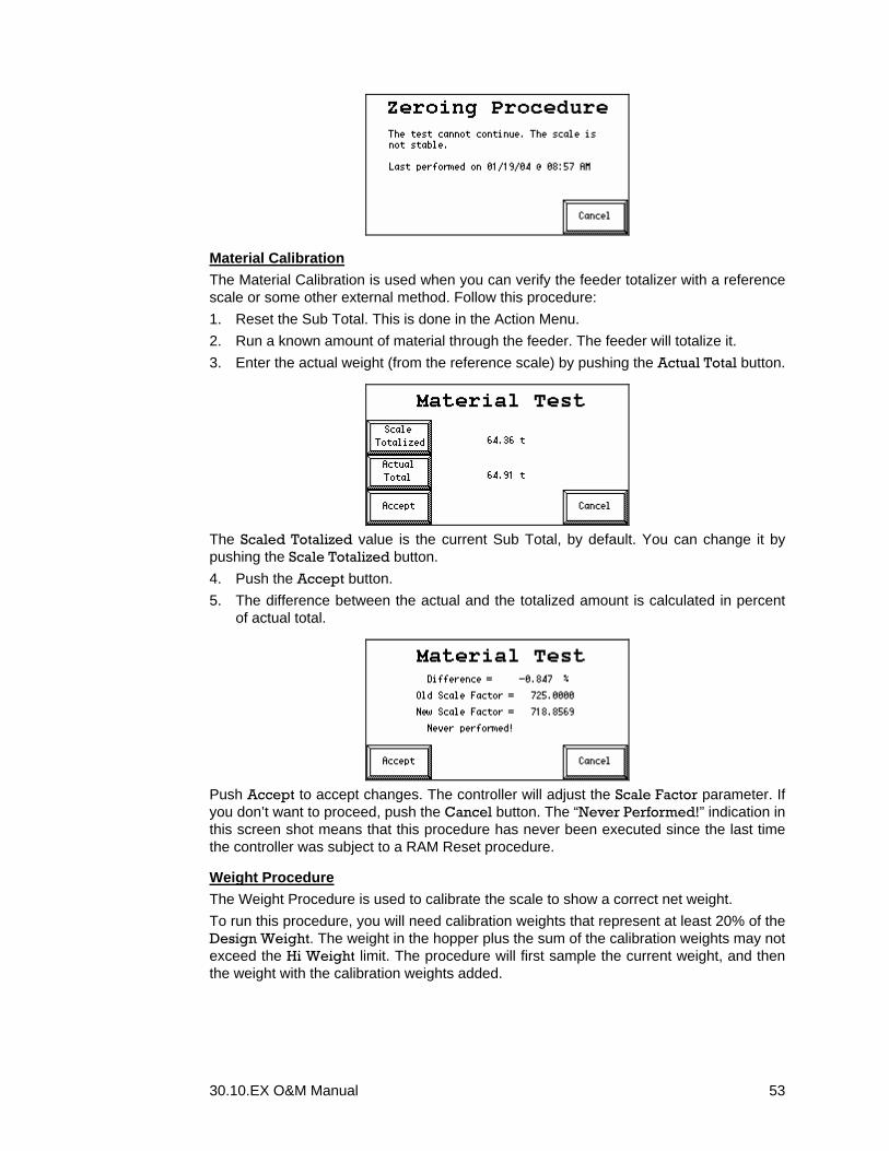
30.10.EX O&M Manual 53
Material Calibration The Material Calibration is used when you can verify the feeder totalizer with a reference scale or some other external method. Follow this procedure: 1. Reset the Sub Total. This is done in the Action Menu. 2. Run a known amount of material through the feeder. The feeder will totalize it. 3. Enter the actual weight (from the reference scale) by pushing the Actual Total button.
The Scaled Totalized value is the current Sub Total, by default. You can change it by pushing the Scale Totalized button. 4. Push the Accept button. 5. The difference between the actual and the totalized amount is calculated in percent
of actual total.
Push Accept to accept changes. The controller will adjust the Scale Factor parameter. If you don’t want to proceed, push the Cancel button. The “Never Performed!” indication in this screen shot means that this procedure has never been executed since the last time the controller was subject to a RAM Reset procedure.
Weight Procedure The Weight Procedure is used to calibrate the scale to show a correct net weight. To run this procedure, you will need calibration weights that represent at least 20% of the Design Weight. The weight in the hopper plus the sum of the calibration weights may not exceed the Hi Weight limit. The procedure will first sample the current weight, and then the weight with the calibration weights added.

30.10.EX O&M Manual 54
To begin the Weight Procedure push the Start button. If the total weight (weight in the hopper plus calibration weights) exceeds the Hi Weight limit, the display will show an Overload Condition screen.
Normally, the start weight is sampled. This requires that the weight value is stable.
In the next screen, the sampled weight before applying the calibration weighs is displayed (“Test Zero”), along with the expected calibration weight. By pushing the Change Value button, you can alter the Calibration Weight value.
Push the OK button and load the calibration weights onto the hopper.
Push Start when the calibration weights are on, and the hopper weight is stable.

30.10.EX O&M Manual 55
The weight is sampled. This requires, again, that the weight value is stable.
This screen indicates that most likely, no calibration weights were applied. Your only option is to push Cancel.
Normally, after the weight has been sampled, the changes that are about to be applied are displayed. You have the option of pushing Accept, to apply the changes, or Cancel to have the controller ignore the entire calibration procedure.
NOTE: The logical input Allow Calibr has to be ON for the Accept button to appear.
Electronic Calibration The Electronic (E-Cal) Procedure is provided as an alternate method to set the Scale Factor. It is used when it is not possible to run either a Material or Weight procedure. The HPAD board can inject a known artificial load cell signal to simulate weight. You must calculate a parameter, called the ECAL mV/V, found in Calibrate Settings. Use the following formula to calculate the E-Cal Live Load mV/V:
Cells Load ofCapacity
Cell Load of ratingmV/V * WeightDesign =mV/V ECAL
If there are more than one load cell supporting the hopper, add the load cells capacities. For example, for three 1000 lb load cells:
Kg1361 2.204
3 * 1000 = Cells Load ofCapacity =
If the load cells are 3 mV/V, and the Design Weight is 400 kg, then:
mV/V 0.88171361
3 * 400 =mV/V ECAL =
Enter ECAL mV/V, in Calibrate Settings, before running the procedure. The hopper must be empty, and a Zero Procedure must be performed immediately before the E-Cal Procedure.
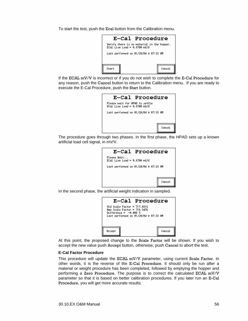
30.10.EX O&M Manual 56
To start the test, push the Ecal button from the Calibration menu.
If the ECAL mV/V is incorrect or if you do not wish to complete the E-Cal Procedure for any reason, push the Cancel button to return to the Calibration menu. If you are ready to execute the E-Cal Procedure, push the Start button.
The procedure goes through two phases. In the first phase, the HPAD sets up a known artificial load cell signal, in mV/V.
In the second phase, the artificial weight indication in sampled.
At this point, the proposed change to the Scale Factor will be shown. If you wish to accept the new value push Accept button, otherwise, push Cancel to abort the test.
E-Cal Factor Procedure This procedure will update the ECAL mV/V parameter, using current Scale Factor. In other words, it is the reverse of the E-Cal Procedure. It should only be run after a material or weight procedure has been completed, followed by emptying the hopper and performing a Zero Procedure. The purpose is to correct the calculated ECAL mV/V parameter so that it is based on better calibration procedures. If you later run an E-Cal Procedure, you will get more accurate results.

30.10.EX O&M Manual 57
To run an E-Cal Factor procedure, select this option from the Calibration menu. From this point on the test runs just like the E-Cal Procedure. The ECAL mV/V parameter will be adjusted. No change is made to the Scale Factor. The calibration of the feeder is not affected.
Analog Input Procedure This procedure allows you to calibrate the two high-resolution analog inputs 1 and 2. You must be able to set the signals at the source to do this.
Press the number of the analog input to calibrate.
Set the signal at the source to represent zero value, typically 4 mA. The live counts will vary accordingly. Since the nominal full scale of the high resolution analog input A/D converter in 1,000,000 counts, the value you see should typically be around 200,000 counts. Push the Snap Zero button. The live value will snap to the New column, Lo row.
Set the signal at the source for full-scale value, typically 20 mA. The live counts should follow the input, and be around 1,000,000 counts. Push the Snap Full button.
The live value will snap to the New column, Hi row.

30.10.EX O&M Manual 58
If the values are acceptable, push the Accept button, followed by the Cancel button, else the Cancel button only.
Start Learning This function allows the controller to “learn” the characteristics of the feeder (hopper and discharge device). To successfully set up your controller using this method, it must be possible to run two fill sequences, with a complete, undisturbed feed cycle in between. During the learning operation, the setpoint must be at a fixed value. This can be accomplished by using the Local setpoint method. The performance of the system will not be optimal while the learning operation is in progress because the controller is adjusting parameters to collect enough data to be able to optimize. Although self-learning is an effective method to set controller parameters, it does not always produce a perfectly tuned controller. In extreme cases, such as very low and very high feedrates, manual tuning methods, used by an experienced technician, works better. The following parameters are set: Parameter Description Feedfactor Represents the output to the feeder drive required to obtain the
design feedrate. Set to 100% at the start of the learn cycle, measured and continuously updated during the cycle.
Upper Feedfactor This is the feedfactor when the weight in the hopper is relatively high, near the fill point. Set to 100% at the start of the learn cycle, and then updated.
Lower Feedfactor This is the feedfactor just before entering fill. It is used together with the High Feedfactor if the “Auto FF Adjust” logical Input is ON. The CSG function uses them together with the weight to set the Speed Demand Signal at feeder start, and to keep the feedrate at the setpoint during fill. Set to 100% at the start of the learn cycle, and then updated.
Feeding Sample Time This is the sample time to use when the controller is normally feeding material. Set, based on the discharge time, according to the table below. See also Sample Rate on page 32 for more information.
Setpoint Filter Set, based on the discharge time, to twice the value of the Average / Loss Slots according to the table below. The highest value is 100. See Dampening & Display on page 32 for more information.
Average Slots Set, based on the discharge time, to Average / Loss Slots according to the table below. See Average Slots on page 27 for more information.
Loss Slots Set, based on the discharge time, to Average / Loss Slots according to the table below. See Loss Slots on page 27 for more information.

30.10.EX O&M Manual 59
Parameter Description Max Slots The largest number for Average and Loss Slots. Set, based on
the discharge time, to Max Slots according to the table below. Feedfactor Dampening This value dampens the action of the CSG controller. Initially
set, based on the discharge time, to half of the value in the table below. At the end of the learn cycle, the value is doubled. See Feed Factor on page 50.
Gate Time Maximized to 10% of the discharge time. This is to avoid a situation where the Gate Time prevents control action for a significant portion of the feed sequence. See Gate Time on page 29 for more information.
Max FdrSpan Initially set to 5% of the Design Feedrate. The final setting depends on the statistics gathered during the learn discharge sequence, but is always between 0.5 and 5% of the Design Feedrate. See Max Fdr Span on page 27 for more information.
CSG Timeout Set, based on the discharge time, to twice the value of High FF time according to the table below. See CSG Timeout on page 27
High FF time This is the hold-off time used by the Feedfactor Adjustment function when sampling the Feedfactor at high weight. Set, based on the discharge time, to High FF time according to the table below.
When the learn cycle is started, which happens the first time the control state changes form Feeding to Filling, the controller calculates the minimum discharge time (Fill Point – Heel Point / Design Feedrate) and pre-sets parameters according to the following Table. Discharge Time (seconds)
Average / Loss Slots
Max Slots
Feeding Sample time
FF Dampening
High FF time
3 – 9 3 10 0.10 1 0.6 10 – 29 3 15 0.20 1 1.2 30 – 99 4 20 0.33 2 3 100 – 299 8 30 0.33 3 5 300 – 999 16 50 0.33 3 11 1000 – 2999 32 100 0.33 4 25 3000 – 9999 54 300 0.33 6 36 10000 – 29999 90 500 0.50 7 100 30000 – 999999 90 500 1.00 9 200 100000 - 90 500 2.00 12 400 During the next discharge cycle, statistics is gathered, without using the PID controller algorithm. At the end of this cycle, parameters are set automatically, based on the performance during the Learn Cycle. While the controller is learning the characteristics of the feeder, you may push the Cancel button to abort the learn process. This will re-instate the parameters used before the learning process was started.
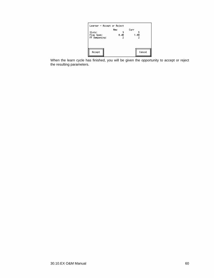
30.10.EX O&M Manual 60
When the learn cycle has finished, you will be given the opportunity to accept or reject the resulting parameters.

30.10.EX O&M Manual 61
DIAGNOSING PROBLEMS
DIAGNOSTIC MENUS Pushing the Diag Menu button in the Action menu takes you to the Diagnostics Menu.
It is usable for troubleshooting. It is not necessary to access these menus under normal operating conditions.
HPAD Diagnostics HPAD stands for “High Performance Analog to Digital converter”. It is the board in the MC³ that takes the Load Cell signal as input and produces a digital value (Counts) as output. This screen helps you diagnose weight indication related problems.
HPAD Diagnostics
Counts HPAD output counts. With default HPAD scaling settings, 0 – 1,000,000 corresponds to 0 – 3 mV/V relative output of the load cell. A value below 255 will turn on the HPAD Underload logical output. A value above 1048320 will turn on the HPAD Underload logical output. Values 0 and 1,048575 indicate that the A/D converter is saturated at one on its end limits. Since the load cell excitation voltage normally is around 10 volts, dividing Counts with 33,333 should give you the approximate load cell input analog voltage in mV.
mV/V Load cell relative output. This value takes into account any non-default HPAD scale settings.
Wt Result of weight calculation. Counts divided by ScaleF minus Z Wt (see below). This is the weight value shown in all main screens.
Z Wt Zero weight – the weight of everything on the load cells when the hopper is empty. The date and time below in the last time a Zero Procedure was performed.
NOTE: Changing the Zero Weight manually will not update this date. ScaleF Scale Factor. Set by calibration procedures or manually. The date
and time below in the last time a Weight, Material or ECal Procedure was performed.
NOTE: Changing the Scale Factor manually will not update this date.
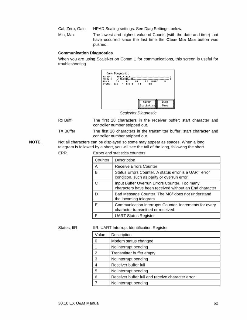
30.10.EX O&M Manual 62
Cal, Zero, Gain HPAD Scaling settings. See Diag Settings, below. Min, Max The lowest and highest value of Counts (with the date and time) that
have occurred since the last time the Clear Min Max button was pushed.
Communication Diagnostics When you are using ScaleNet on Comm 1 for communications, this screen is useful for troubleshooting.
ScaleNet Diagnostic
Rx Buff The first 28 characters in the receiver buffer; start character and controller number stripped out.
TX Buffer The first 28 characters in the transmitter buffer; start character and controller number stripped out.
NOTE: Not all characters can be displayed so some may appear as spaces. When a long telegram is followed by a short, you will see the tail of the long, following the short. ERR Errors and statistics counters
Counter Description A Receive Errors Counter B Status Errors Counter. A status error is a UART error
condition, such as parity or overrun error. C Input Buffer Overrun Errors Counter. Too many
characters have been received without an End character D Bad Message Counter. The MC³ does not understand
the incoming telegram. E Communication Interrupts Counter. Increments for every
character transmitted or received. F UART Status Register
States, IIR IIR, UART Interrupt Identification Register
Value Description 0 Modem status changed 1 No interrupt pending 2 Transmitter buffer empty 3 No interrupt pending 4 Receiver buffer full 5 No interrupt pending 6 Receiver buffer full and receive character error 7 No interrupt pending

30.10.EX O&M Manual 63
States, LSR UART Line Status Register, bit encoded Bit Description
Bit 7 Not used. Bit 6 Transmitter Empty
1 - No byte in transmitter hold or transmitter shift register 0 - One byte in transmitter hold or transmitter shift register
Bit 5 Transmitter Buffer Empty 1 - no byte in Transmitter Hold Register 0 - one byte in Transmitter Hold Register
Bit 4 Break. 1 – Break Detected 0 - No Break Detected
Bit 3 Framing Error 1 – Framing Error Detected 0 - No Framing Error Detected
Bit 2 Parity Error 1 – Parity Error Detected 0 - No Parity Error Detected
Bit 1 Overrun Error 1 – Overrun Error Detected 0 - No overrun error Detected
Bit 0 Receive Data Ready 1 - Received data in receiver buffer register 0 - No Received Data
States, RX Receiver Driver State
Value Description 0 Waiting for start char 1 Waiting for controller address 2 Addressed, Buffering chars 3 Message received, not processed yet
States, TX Transmitter Driver State
Value Description 0 Transmitter passive 1 Transmitter active 2 The last byte of the telegram is being transmitted
Calib History Display

30.10.EX O&M Manual 64
This screen displays the calibration history for the four last calibration occurrences. You can see current and previous Zero Weight (Z ld) and Scale Factor (Scl F); analog with the date and time they became valid. Zero Load updates when you run a Zero Procedure. Scale Factor updates when you run a Weight, Material or ECal procedure. See Calibrating Your Controller on page 51.
Analog Diagnostics The top section displays the selected function (SCR Out, Feedrate, Weight etc.) and type (0-20 mA or 4-20 mA) for each of the Analog outputs. The “Actual” column in the output section displays the engineering value, used to generate the output. The “EST-mA” column displays the estimated current output in mA for the output. See Analog Outputs on page 35 for more information. As long as standard output scaling is used, the translation between engineering value and output current is straightforward. If you have to use non-standard output scaling, this is where you can see the effect of your changes to the analog output scaling. If you are using voltage output, divide EST-mA with two.
Analog Diagnostics
Analog inputs use a 20 bit A/D converter, just like the HPAD. In the Input section, you can see • The counts, directly from the A/D converter. For a 4-20 mA or 2-10V input, the value
should stay between approximately 200,000 and 1,000,000. • The percentage of full scale of the analog input. • The calculated engineering value based on the scaling. The last row in this screens shot is what you will see if there is no second PCIO board installed. See Analog Inputs on page 33.
Digital Diagnostics The screen offers two views of all digital input and outputs. The mapping view displays mapping, qualifiers and status of all physical outputs and all logical inputs. The List View displays either all logical I/O points or all physical I/O points. For more information see Digital I/O Mapping on page 37.
Mapping view
Physical Outputs and Logical Inputs

30.10.EX O&M Manual 65
The button between the up and down arrows toggles between Outputs and Inputs. Use the up and down arrow buttons to page the digital I/O points. This screen displays the current mapping, properties and status for the logical inputs and physical outputs.
NOTE: You can only see used (mapped) logical outputs and physical inputs in this view. To see all logical outputs and physical inputs, push the Display List button. This will take you to the List View. There are seven columns in the mapping view: ST (Status) Current state of I/O point. - OFF - ON Physical Name of physical I/O point Logical Name of logical I/O point IV (Inversion) 1 Physical I/O point is inverted. FC (Forcing) 0 – Physical I/O point Forced Off. 1 – Physical I/O point Forced On. FW (Qualifiers) F – Logical I/O point generates a Fault when on. W – Logical I/O point
generates a Warning when on.
List View
In the List View, you can see status and properties of all logical or physical I/O points, regardless if they are used or not, but you can’t se the mapping. Logical outputs are listed before the logical inputs. Physical inputs are listed before physical outputs. Logical list view has 4 columns: ST (Status) Current state of logical I/O point. - OFF - ON Logical Name of logical I/O point OUT – Output, IN – Input, I/O – both Input and Output. F – Logical I/O point generates a Fault when on. W – Logical I/O point
generates a Warning when on. Physical list view has 5 columns ST (Status) Current state of physical I/O point. - OFF - ON Physical Name of physical I/O point OUT – Output, IN – Input, I/O – both Input and Output. I - Physical I/O point is inverted. 0 – Physical I/O point Forced Off. 1 – Physical I/O point Forced On.
Faults and Warnings Diagnostics Pushing the Faults or Warnings button allows you to see the Faults or Warnings screen even if there are no Faults and Warnings active. This is useful when you have finished all your Digital I/O configurations. See Warnings on page 16 and Faults on page 17, as well as Digital I/O Mapping on page 37.
DF1 Diagnostics There are two diagnostics screen available for troubleshooting DF1 communications.
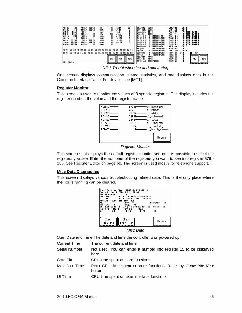
30.10.EX O&M Manual 66
DF-1 Troubleshooting and monitoring
One screen displays communication related statistics, and one displays data in the Common Interface Table. For details, see [MCT].
Register Monitor This screen is used to monitor the values of 8 specific registers. The display includes the register number, the value and the register name.
Register Monitor
This screen shot displays the default register monitor set-up. It is possible to select the registers you see. Enter the numbers of the registers you want to see into register 379 - 386. See Register Editor on page 69. The screen is used mostly for telephone support.
Misc Data Diagnostics This screen displays various troubleshooting related data. This is the only place where the hours running can be cleared.
Misc Datc
Start Date and Time The date and time the controller was powered up. Current Time The current date and time Serial Number Not used. You can enter a number into register 15 to be displayed
here. Core Time CPU time spent on core functions. Max Core Time Peak CPU time spent on core functions. Reset by Clear Min Max
button UI Time CPU time spent on user interface functions.
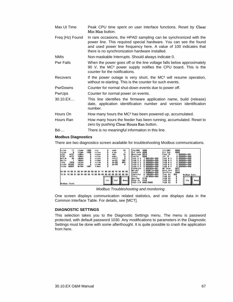
30.10.EX O&M Manual 67
Max UI Time Peak CPU time spent on user interface functions. Reset by Clear Min Max button.
Freq (Hz) Found In rare occasions, the HPAD sampling can be synchronized with the power line. This required special hardware. You can see the found and used power line frequency here. A value of 100 indicates that there is no synchronization hardware installed.
NMIs Non-maskable Interrupts. Should always indicate 0. Pwr Fails When the power goes off or the line voltage falls below approximately
90 V, the MC³ power supply notifies the CPU board. This is the counter for the notifications.
Recovers If the power outage is very short, the MC³ will resume operation, without re-starting. This is the counter for such events.
PwrDowns Counter for normal shut-down events due to power off. PwrUps Counter for normal power on events. 30.10.EX… This line identifies the firmware application name, build (release)
date, application identification number and version identification number.
Hours On How many hours the MC³ has been powered up, accumulated. Hours Ran How many hours the feeder has been running, accumulated. Reset to
zero by pushing Clear Hours Ran button.
Bd-… There is no meaningful information in this line.
Modbus Diagnostics There are two diagnostics screen available for troubleshooting Modbus communications.
Modbus Troubleshooting and monitoring
One screen displays communication related statistics, and one displays data in the Common Interface Table. For details, see [MCT].
DIAGNOSTIC SETTINGS This selection takes you to the Diagnostic Settings menu. The menu is password protected, with default password 1030. Any modifications to parameters in the Diagnostic Settings must be done with some afterthought. It is quite possible to crash the application from here.
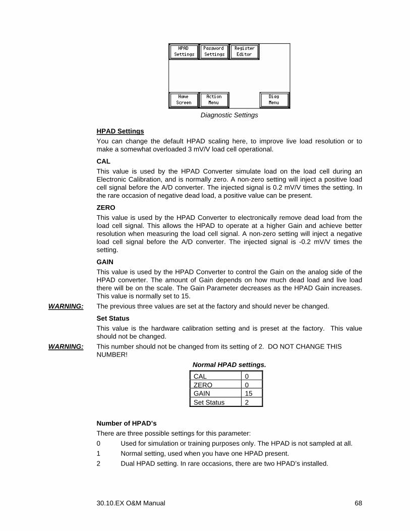
30.10.EX O&M Manual 68
Diagnostic Settings
HPAD Settings You can change the default HPAD scaling here, to improve live load resolution or to make a somewhat overloaded 3 mV/V load cell operational.
CAL This value is used by the HPAD Converter simulate load on the load cell during an Electronic Calibration, and is normally zero. A non-zero setting will inject a positive load cell signal before the A/D converter. The injected signal is 0.2 mV/V times the setting. In the rare occasion of negative dead load, a positive value can be present.
ZERO This value is used by the HPAD Converter to electronically remove dead load from the load cell signal. This allows the HPAD to operate at a higher Gain and achieve better resolution when measuring the load cell signal. A non-zero setting will inject a negative load cell signal before the A/D converter. The injected signal is -0.2 mV/V times the setting.
GAIN This value is used by the HPAD Converter to control the Gain on the analog side of the HPAD converter. The amount of Gain depends on how much dead load and live load there will be on the scale. The Gain Parameter decreases as the HPAD Gain increases. This value is normally set to 15.
WARNING: The previous three values are set at the factory and should never be changed.
Set Status This value is the hardware calibration setting and is preset at the factory. This value should not be changed.
WARNING: This number should not be changed from its setting of 2. DO NOT CHANGE THIS NUMBER!
Normal HPAD settings.
CAL 0ZERO 0GAIN 15Set Status 2
Number of HPAD’s There are three possible settings for this parameter: 0 Used for simulation or training purposes only. The HPAD is not sampled at all. 1 Normal setting, used when you have one HPAD present. 2 Dual HPAD setting. In rare occasions, there are two HPAD’s installed.
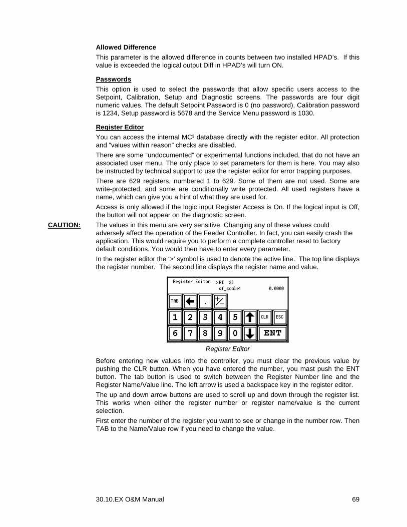
30.10.EX O&M Manual 69
Allowed Difference This parameter is the allowed difference in counts between two installed HPAD’s. If this value is exceeded the logical output Diff in HPAD’s will turn ON.
Passwords This option is used to select the passwords that allow specific users access to the Setpoint, Calibration, Setup and Diagnostic screens. The passwords are four digit numeric values. The default Setpoint Password is 0 (no password), Calibration password is 1234, Setup password is 5678 and the Service Menu password is 1030.
Register Editor You can access the internal MC³ database directly with the register editor. All protection and “values within reason” checks are disabled. There are some “undocumented” or experimental functions included, that do not have an associated user menu. The only place to set parameters for them is here. You may also be instructed by technical support to use the register editor for error trapping purposes. There are 629 registers, numbered 1 to 629. Some of them are not used. Some are write-protected, and some are conditionally write protected. All used registers have a name, which can give you a hint of what they are used for. Access is only allowed if the logic input Register Access is On. If the logical input is Off, the button will not appear on the diagnostic screen.
CAUTION: The values in this menu are very sensitive. Changing any of these values could adversely affect the operation of the Feeder Controller. In fact, you can easily crash the application. This would require you to perform a complete controller reset to factory default conditions. You would then have to enter every parameter. In the register editor the ‘>’ symbol is used to denote the active line. The top line displays the register number. The second line displays the register name and value.
Register Editor
Before entering new values into the controller, you must clear the previous value by pushing the CLR button. When you have entered the number, you mast push the ENT button. The tab button is used to switch between the Register Number line and the Register Name/Value line. The left arrow is used a backspace key in the register editor. The up and down arrow buttons are used to scroll up and down through the register list. This works when either the register number or register name/value is the current selection. First enter the number of the register you want to see or change in the number row. Then TAB to the Name/Value row if you need to change the value.