mc-f firewire cameras - robot store (hk · ieee 1394 digital progressive scan ccd camera mc-f...
TRANSCRIPT
IEEE 1394 DIGITAL PROGRESSIVE SCAN CCD CAMERA
MC-F Firewire Cameras
User’s Manual
Document Revision Number : 1.0B
1stVision Inc. 978-474-0044
www.1stvision.com
ii MC-FCams User’s Manual Rev1.0B
© 1stVision. All rights reserved
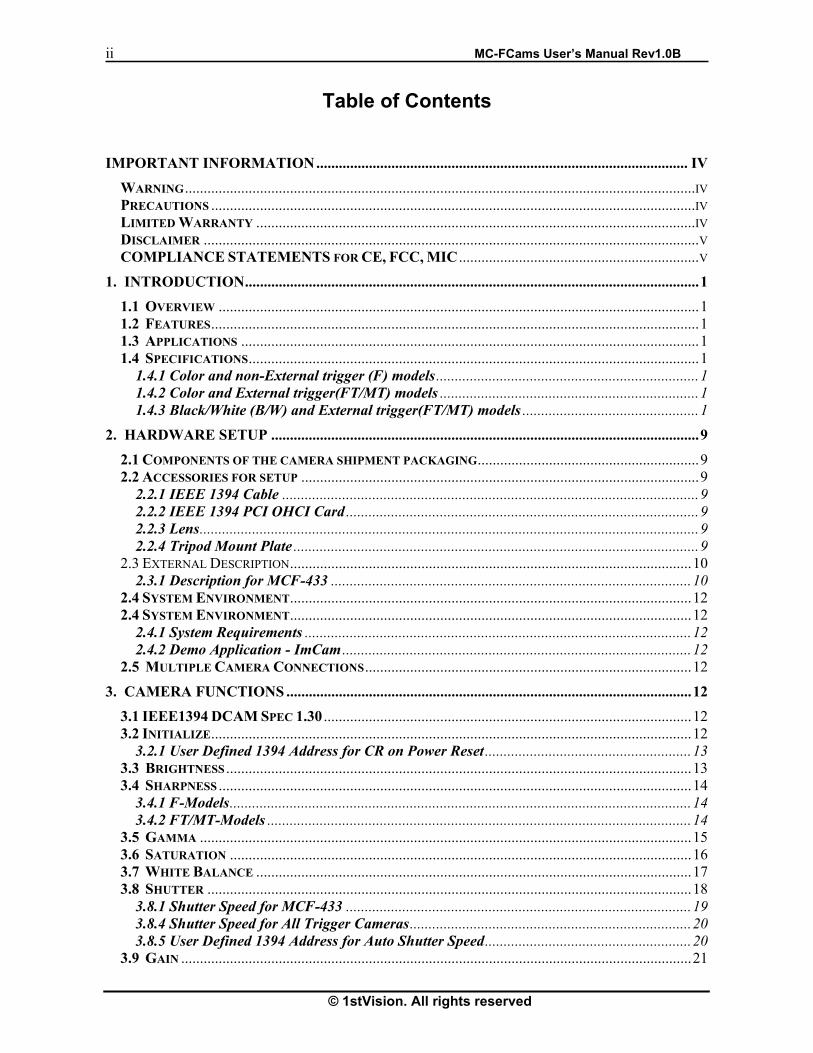
Table of Contents
IMPORTANT INFORMATION................................................................................................... IV
WARNING........................................................................................................................................IV PRECAUTIONS .................................................................................................................................IV LIMITED WARRANTY .....................................................................................................................IV DISCLAIMER ....................................................................................................................................V COMPLIANCE STATEMENTS FOR CE, FCC, MIC ................................................................V
1. INTRODUCTION.........................................................................................................................1
1.1 OVERVIEW ................................................................................................................................1 1.2 FEATURES..................................................................................................................................1 1.3 APPLICATIONS ..........................................................................................................................1 1.4 SPECIFICATIONS........................................................................................................................1
1.4.1 Color and non-External trigger (F) models ......................................................................1 1.4.2 Color and External trigger(FT/MT) models .....................................................................1 1.4.3 Black/White (B/W) and External trigger(FT/MT) models ...............................................1
2. HARDWARE SETUP ..................................................................................................................9
2.1 COMPONENTS OF THE CAMERA SHIPMENT PACKAGING...........................................................9 2.2 ACCESSORIES FOR SETUP ..........................................................................................................9
2.2.1 IEEE 1394 Cable ...............................................................................................................9 2.2.2 IEEE 1394 PCI OHCI Card ..............................................................................................9 2.2.3 Lens.....................................................................................................................................9 2.2.4 Tripod Mount Plate ............................................................................................................9
2.3 EXTERNAL DESCRIPTION...........................................................................................................10 2.3.1 Description for MCF-433 ................................................................................................10
2.4 SYSTEM ENVIRONMENT...........................................................................................................12 2.4 SYSTEM ENVIRONMENT...........................................................................................................12
2.4.1 System Requirements .......................................................................................................12 2.4.2 Demo Application - ImCam .............................................................................................12
2.5 MULTIPLE CAMERA CONNECTIONS.......................................................................................12
3. CAMERA FUNCTIONS ............................................................................................................12
3.1 IEEE1394 DCAM SPEC 1.30 ..................................................................................................12 3.2 INITIALIZE................................................................................................................................12
3.2.1 User Defined 1394 Address for CR on Power Reset .......................................................13 3.3 BRIGHTNESS ............................................................................................................................13 3.4 SHARPNESS ..............................................................................................................................14
3.4.1 F-Models...........................................................................................................................14 3.4.2 FT/MT-Models .................................................................................................................14
3.5 GAMMA ...................................................................................................................................15 3.6 SATURATION ...........................................................................................................................16 3.7 WHITE BALANCE ....................................................................................................................17 3.8 SHUTTER .................................................................................................................................18
3.8.1 Shutter Speed for MCF-433 ............................................................................................19 3.8.4 Shutter Speed for All Trigger Cameras...........................................................................20 3.8.5 User Defined 1394 Address for Auto Shutter Speed.......................................................20
3.9 GAIN ........................................................................................................................................21

MCF Cams User’s Manual Rev1.0B iii
© 1stVision. All rights reserved
3.9.1 User Defined Address for Auto Gain only for FT/MT Models ......................................22 3.10 AUTO EXPOSURE...................................................................................................................22 3.11 OPTICAL FILTER....................................................................................................................23 3.12 TRIGGER ................................................................................................................................24
3.12.1 User Defined 1394 Address for Trigger Features.........................................................24 3.12.2 Electrical Specification for Ext. Trigger and Strobe signal ........................................25 3.12.3 Trigger & Strobe signal relation ...................................................................................25 3.12.4 Trigger Timing Diagram ...............................................................................................26
3.13 AVAILABLE VIDEO FORMATS, MODES, & FRAME RATES ...................................................27 3.13.1 Standards for MCF-433 Color Camera ........................................................................27
3.14 OUTPUT DATA FORMAT FOR COLOR CAMERAS....................................................................28
4. CAMERA DIMENSIONS..........................................................................................................29
4.1 MCF-433.................................................................................................................................29 4.3 TRIGGER MODELS : MC-FYYYX ( X = B/W OR COLOR, YYY = RESOLTION SIZE)...............30
5. TROUBLESHOOTING .............................................................................................................31
5.1 FAULT CHECKING USING THE CAMERA LED .......................................................................31 5.1.1 Fault Checking Using the Camera LED.........................................................................31 5.1.2 Green LED .......................................................................................................................31
5.2 ERROR MESSAGES WHILE RUNNING THE DEMO APPLICATION ..........................................31 5.2.1 “Can not Find the 1394 Camera” ..................................................................................31 5.2.2 “Can not Find the 1394 ...................................................................................................32 5.2.3 Common Solutions ...........................................................................................................32
6. TECHNICAL SUPPORT INFORMATION............................................................................32
MCF Cams User’s Manual Rev1.0B iv
© 1stVision. All rights reserved
Do not remove screws or covers to prevent fire or electric shock. Do not expose this camera to rain, directly to sunlight or moisture, nor try to operate it in wet areas. Do not attempt to remove camera cover nor modify any unit. Warranty will be voided against the damage caused by you or any other equipment.
Before using this camera, please carefully read User’s Manual to use the product better. The product has been safely designed to prevent malfunctions and accidents. Please observe strictly the handling precautions below. If faults are suspected, consult the shop for IMI products nearest you without attempting to disassemble the camera yourself.
Important information
Warning
Precautions
• Do not attempt to disassemble, modify, or repair the camera. • Do not directly shoot sunlight or strong spotlight to the camera for a long period as it
may cause CCD blooming and permanent damages. • Do not operate the camera beyond the temperature range and avoid using the
camera over 90% humidity. • Do not use unregulated power supply source. • Do not clean CCD faceplate with fingers or any hard objects other than Lens tissue
or a cotton tipped applicator and ethanol. • Do not use the strong or abrasive detergents when cleaning the camera body.
Limited Warranty
1STVISION warrants only the original components to be free from defects in material for one year from the purchase date. This warranty covers failures or damages due to defects in material, which would occur during normal use. It does not cover damages or failures, which result from shipment, mishandling, abuse, misuse, or modification. Any damage caused by improper handling will not be repaired by 1STVISION. A Return Material Authorization (RMA) number is required prior to returning any 1STVISION product for repair or replacement. This proprietary document may not be reproduced or photocopied without the consent of 1STVISION, which doesn’t make any warranty or assume or responsibility for the errors which may not appear in this document. 1STVISION reserves the right to make changes without notice or obligation. For technical assistance, please email to [email protected]

MCF Cams User’s Manual Rev1.0B v
© 1stVision. All rights reserved
Disclaimer
The information in this document has been carefully checked and is believed to be entirely reliable. However, no responsibility is assumed for inaccuracies, nor is any responsibility assumed by 1stVision for its use; nor for any infringements against the patents or the other rights of the third party resulting from its use. No license is granted under any patent or the patent rights of 1STVISION. 1STVISION points out that there is no legal obligation to documenting internal relationships in any functional module of its products, which is realized in either hardware or software. 1STVISION reserves the right to make changes in specifications, functions or designs at any time and without any notice. 1STVISION products are not authorized for use as components in life support devices or systems intended to surgically be implanted into the body or intended to support or sustain life Product and the company names in this document may be the trademarks and trade-names of their respective owner and are hereby acknowledged. Copyright © 2004 1STVISION All rights reserved.
COMPLIANCE STATEMENTS for CE, FCC, MIC To meet EC requirements, shielded cables must be connected to other devices for these cameras. These cameras have been tested in the compliant environment of a typical class A. It is assumed that the camera has been tested and found to comply with the limits for a Class A digital device, pursuant to Part 15 of the FCC Rules. These limits are designed to provide the reasonable protection against harmful interference in a residential installation. This equipment generates uses and can radiate radio frequency energy and, if not installed and used in accordance with the instructions, may cause harmful interference to radio communications. However, there is no guarantee that interference will not occur in a particular installation.

vi MCFCams User’s Manual Rev1.0B
1stVision Inc. All rights reserved
Blank Page

MCF Cams User’s Manual Rev1.0B 1
© 1stVision. All rights reserved
1. Introduction
1.1 Overview MCF camera series are an IEEE 1394 compliant (FirewireTM) progressive area scan color or B/W CCD cameras designed for industrial imaging applications. MCF cameras use the IEEE 1394 digital interface to streaming real-time uncompressed color image sequences in high resolution. The IEEE 1394 interface supports camera power, camera control and image data through only single cable, so user can use these cameras with simple cable connections.
What is the IEEE 1394 ? The IEEE 1394 is the international standard about serial bus for transfer digital data up to 400Mbps, 800Mbps and 1.6Gbps. It is also capable of “Isochronous transmission” for transmits data real-time up to 64 channels MCF camera family is a compact size, c-mount type and fully supports IEEE 1394-1995, IEEE 1394a-2000 and IIDC Spec. 1.30. MCF camera family consists of several models, which are equipped with high sensitivity progressive scan CCD and have very different imager sizes each of 1/4, 1/3, 1/2, 2/3 inches. MCF camera family also supports various resolution modes for CIF, VGA, SVGA, XGA, SXGA and UXGA for each B/W and color models.
1.2 Features
� Low smear and excellent anti-blooming � Continuous variable shutter speed � High sensitivity and low dark current � High speed digital interface up to 400Mbps � Supports external trigger and power for trigger models
1.3 Applications
IMI-FCams can be use in machine vision, stereo vision, inspection, character recognition, medical, biomedical imaging, microscopy, traffic control, surveillance, RFID and other scientific or industrial applications
1.4 Specifications
1.4.1 Color and non-External trigger (F) models � Standard models : MC-F433
1.4.2 Color and External trigger(FT/MT) models � Standard models : � Double speed Models � High MegaPixel Models :
1.4.3 Black/White (B/W) and External trigger(FT/MT) models � Standard models � Double speed Models :MC-F333MT � High MegaPixel Models

2 MCFCams User’s Manual Rev1.0B
1stVision Inc. All rights reserved
Rel
ativ
e R
espo
nse
Rel
ativ
e R
espo
nse
Features MCF-433 Image Device 1/2-inch Interline
Wfine CCD 1/3-inch Interline
Wfine CCD 1/4-inch Interline
Wfine CCD
Effective pixels 1,450,000 pixel 1392 (H) x 1040 (V)
800,000 pixel 1034 (H) x 779 (V)
330,000 pixel 659 (H) x 494 (V)
Picture Size, Resolution
SXGA, XGA SVGA, VGA
XGA, SVGA VGA
VGA, QVGA QCIF
Data Path YUV422 YUV422 YUV411, RGB24 CELL size 4.65um x 4.65um 4.65um x 4.65um 5.60um x 5.60um Scanning system Progressive Scan Frame rate 7.5fps at full resolution 15 fps at full resolution 30 fps at full resolution Synchronization Internal Lens mount C-mount Digital Interface IEEE 1394 2(Two) Ports and IIDC V1.3 Transfer Rate (fps) 400 Mbps/max Gain Control AGC (0–18 dB), FIX (0dB), Manual (0-18dB) Auto White Balance Auto or Manual Shutter Speed 1/20,000 ~ 2 sec 1/3,000 ~ 1/30 sec Gamma 1.0 Approx Min. Illumination 22Lux at F1.4 15Lux at F2.0 20Lux at F2.0 S/N ratio 56dB or better Power supply voltage 12VDC from IEEE1394 Cable Power Consumption 3.5 W at 12VDC approx. 1 W at 12VDC Weight 300gr. Approx. 200 gr. Approx. External Dimensions 64 (W) x 64 (H) x 60 (D) mm 44(W)x32(H)x92(D) Operation Temp. -5 to + 45 0C Storage Temp. -20 to + 60 0C Regulations FCC, CE, MIC Supplied Accessories Lens cover, OLPF, User’s Manual
◆ Specifications are subject to change without notice
Spectral Sensitivity for with only CCD
Wave Length [nm]
Spectral Sensitivity for MCF-433with only CCD
Spectral Sensitivity for with only CCD
Wave Length [nm]
Wave Length [nm]
Rel
ativ
e R
espo
nse
Table 1-1 Color and non-External trigger models

MCF Cams User’s Manual Rev1.0B 3
© 1stVision. All rights reserved
Features Image Device 1/3-inch Interline
Wfine CCD 1/4-inch Interline
Wfine CCD Effective pixels 330,000 pixel 659(H) x 494(V) Picture Size 640 x 480 Data Path 8 bit Raw RGB CELL size 7.40 um x 7.40 um 5.60 um x 5.60 um Scanning system Progressive Scan
Frame rate 60, 30, 15, 7.5, 3.75,1.875 30, 15, 7.5, 3.75,1.875
Synchronization External Trigger at falling edge or S/W Trigger Lens mount C-mount Digital Interface 1(One) Port for IEEE 1394 6 pin and IIDC v1.30 Transfer Rate (fps) 400 Mbps/max Gain Control 2 ~ 36 dB White Balance Auto / Manual for only color processing Shutter Speed 1 usec ~ 65 sec Gamma 1.0 Approx Strobe Output Signal Option S/N ratio 56 dB or better Power supply voltage 8 - 30VDC from IEEE1394 Camera Cable Power Consumption 2.8 W at 12VDC 2.7 W at 12VDC 2.2 W at 12VDC Weight 300 gr. approx. External Dimensions 64 (W) x 64 (H) x 60 (D) mm Operation Temp. -5 to + 45 0C Storage Temp. -20 to + 60 0C Regulations FCC, CE, MIC Supplied Accessories Lens cover, User’s Manual
Table 1-2 Color and External trigger (FT/MT) d l
Spectral Sensitivity for with only CCD
Spectral Sensitivity for with only CCD
◆ Specifications are subject to change without notice
Wave Length [nm]
Wave Length [nm]
Rel
ativ
e R
espo
nse
Rel
ativ
e R
espo
nse

4 MCFCams User’s Manual Rev1.0B
1stVision Inc. All rights reserved
Features Image Device 1/2-inch Interline Wfine CCD 1/3-inch Interline Wfine CCD Effective pixels 1,450,000 pixel 1392(H) x 1040(V) 800,000 pixel 1034(H) x 779(V)
Picture Size 1280 x 960, 1024 x 768, 800 x 600, 640 x 480 1024 x 768, 800 x 600, 640 x 480
Data Path 8 bit or 10 bit Raw RGB CELL size 4.65um x 4.65um 4.65um x 4.65um Scanning system Progressive Scan
Frame rate 15, 7.5, 3.75, 1.875 7.5, 3.75, 1.875 30, 15, 7.5,
3.75,1.875 15, 7.5,
3.75, 1.875 Synchronization External Trigger at falling edge and S/W Trigger Lens mount C-mount Digital Interface 1(One) Port for IEEE 1394 6 pin and IIDC v1.30 Transfer Rate (fps) 400 Mbps/max Gain Control 2 ~ 36 dB White Balance Auto / Manual for only Color processing Shutter Speed 1 usec ~ 65 sec Gamma 0.4 ~ 2.5 Strobe Output Signal Option RS-232C comm.. Option S/N ratio 56 dB or better Power supply voltage 8 - 30VDC from IEEE1394 Camera Cable Power Consumption 2.8 W at 12VDC 2.4 W at 12VDC 2.6 W at 12VDC 2.4W at 12VDC Weight 300 gr. approx. External Dimensions 64 (W) x 64 (H) x 60 (D) mm Operation Temp. -5 to + 45 0C Storage Temp. -20 to + 60 0C Regulations FCC, CE, MIC Supplied Accessories Lens cover, User’s Manual
◆ Specifications are subject to change without notice
Spectral Sensitivity for with only CCD
Spectral Sensitivity for with only CCD
Rel
ativ
e R
espo
nse
Rel
ativ
e R
espo
nse
Wave Length [nm]
Wave Length [nm]

MCF Cams User’s Manual Rev1.0B 5
© 1stVision. All rights reserved
Features Image Device 1/1.8-inch Interline Wfine CCD 2/3-inch Interline Wfine CCD Effective pixels 2,010,000 pixel 1628(H) x 1236(V) 1,450,000 pixel 1392(H) x 1040(V)
Picture Size 1600 x 1200, 1280 x 960, 1024 x 768, 800 x 600, 640 x 480
1280 x 960, 1024 x 768, 800 x 600, 640 x 480
Data Path 8 bit or 12 bit Raw RGB 8 bit or 12 bit Raw RGB CELL size 4.40 um x 4.40 um 6.45 um x 6.45 um Scanning system Progressive Scan Frame rate (fps) 10, 5, 2.5, 1.25 15, 7.5, 3.75, 1.875 Synchronization External Trigger at falling edge and S/W Trigger Lens mount C-mount Digital Interface 1(One) Port for IEEE 1394 6 pin and IIDC v1.30 Transfer Rate 400 Mbps/max Gain Control 2 ~ 36 dB White Balance Auto / Manual for only Color processing Shutter Speed 1 usec ~ 65 sec Gamma 1.0 Approx Strobe Output Signal Option RS-232C comm.. Option S/N ratio 56 dB or better Power supply voltage 8 - 30VDC from IEEE1394 Camera Cable Power Consumption 3.2 W at 12VDC 3.5 W at 12VDC Weight 300 gr. approx. External Dimensions 64 (W) x 64 (H) x 60 (D) mm Operation Temp. -5 to + 45 0C Storage Temp. -20 to + 60 0C Regulations FCC, CE, MIC Supplied Accessories Lens cover, User’s Manual
Rel
ativ
e R
espo
nse
Rel
ativ
e R
espo
nse
Wave Length [nm]
Wave Length [nm]
Spectral Sensitivity for with only CCD
Spectral Sensitivity for with only CCD
◆ Specifications are subject to change without notice

6 MCFCams User’s Manual Rev1.0B
1stVision Inc. All rights reserved
Features MC-F333MT Image Device 1/3-inch Interline
Wfine CCD 1/4-inch Interline
Wfine CCD Effective pixels 330,000 pixel 659(H) x 494(V) Picture Size 640 x 480 Data Path 8 bit B/W CELL size 7.40 um x 7.40 um 5.60 um x 5.60 um Scanning system Progressive Scan Frame rate (fps) 60, 30, 15, 7.5, 3.75,1.875 30, 15, 7.5, 3.75,1.875 Synchronization External Trigger at falling edge or S/W Trigger Lens mount C-mount Digital Interface 1(One) Port for IEEE 1394 6 pin and IIDC v1.30 Transfer Rate 400 Mbps/max Gain Control 2 ~ 36 dB White Balance Auto / Manual for only Color camera Shutter Speed 1 usec ~ 65 sec Gamma 1.0 Approx Strobe Output Signal Option S/N ratio 56 dB or better Power supply voltage 8 - 30VDC from IEEE1394 Camera Cable Power Consumption 2.8 W at 12VDC 2.7 W at 12VDC 2.2 W at 12VDC Weight 300 gr. approx. External Dimensions 64 (W) x 64 (H) x 60 (D) mm Operation Temp. -5 to + 45 0C Storage Temp. -20 to + 60 0C Regulations FCC, CE, MIC Supplied Accessories Lens cover, User’s Manual
Table 1.3 B/W and External trigger (FT) models
Rel
ativ
e R
espo
nse
Rel
ativ
e R
espo
nse
Wave Length [nm]
Wave Length [nm]
Spectral Sensitivity for MC-F333MT with only CCD
Spectral Sensitivity for with only CCD
◆ Specifications are subject to change without notice

MCF Cams User’s Manual Rev1.0B 7
© 1stVision. All rights reserved
Features Image Device 1/2-inch Interline Wfine CCD 1/3-inch Interline Wfine CCD Effective pixels 1,450,000 pixel 1392(H) x 1040(V) 800,000 pixel 1034(H) x 779(V)
Picture Size 1280 x 960, 1024 x 768, 800 x 600, 640 x 480 1024 x 768, 800 x 600, 640 x 480
Data Path 8 bit or 10 bit B/W CELL size 4.65um x 4.65um 4.65um x 4.65um Scanning system Progressive Scan
Frame rate (fps) 15, 7.5, 3.75, 1.875 7.5, 3.75, 1.875 30, 15, 7.5,
3.75,1.875 15, 7.5,
3.75, 1.875 Synchronization External Trigger at falling edge or S/W Trigger Lens mount C-mount Digital Interface 1(One) Port for IEEE 1394 6 pin and IIDC v1.30 Transfer Rate 400 Mbps/max Gain Control 2 ~ 36 dB White Balance Auto / Manual for only Color camera Shutter Speed 1 usec ~ 65 sec Gamma 0.4 ~ 2.5 Strobe Output Signal Option RS-232C comm.. Option S/N ratio 56 dB or better Power supply voltage 8 - 30VDC from IEEE1394 Camera Cable
Power Consumption 2.7 W at 12VDC 2.3 W at 12VDC 2.5 W at 12VDC 2.2W at 12VDC Weight 300 gr. approx. External Dimensions 64 (W) x 64 (H) x 60 (D) mm Operation Temp. -5 to + 45 0C Storage Temp. -20 to + 60 0C Regulations FCC, CE, MIC Supplied Accessories Lens cover, User’s Manual
Rel
ativ
e R
espo
nse
Rel
ativ
e R
espo
nse
Wave Length [nm]
Wave Length [nm]
◆ Specifications are subject to change without notice
Spectral Sensitivity for IMB-140FT and IMB-141FT with only CCD
Spectral Sensitivity for IMB-80FT and IMB-81FT with only

8 MCFCams User’s Manual Rev1.0B
1stVision Inc. All rights reserved
Features Image Device 1/1.8-inch Interline Wfine CCD 2/3-inch Interline Wfine CCD Effective pixels 2,010,000 pixel 1628(H) x 1236(V) 1,450,000 pixel 1392(H) x 1040(V)
Picture Size 1600 x 1200, 1280 x 960, 1024 x 768, 800 x 600, 640 x 480
1280 x 960, 1024 x 768, 800 x 600, 640 x 480
Data Path 8 bit or 12 bit B/W 8 bit or 12 bit B/W CELL size 4.40 um x 4.40 um 6.45 um x 6.45 um Scanning system Progressive Scan Frame rate (FPS) 10, 5, 2.5, 1.25 15, 7.5, 3.75, 1.875 Synchronization External Trigger at falling edge and S/W Trigger Lens mount C-mount Digital Interface 1(One) Port for IEEE 1394 6 pin and IIDC v1.30 Transfer Rate 400 Mbps/max Gain Control 2 ~ 36 dB White Balance Auto / Manual for only Color processing Shutter Speed 1 usec ~ 65 sec Gamma 1.0 Approx Strobe Output Signal Option RS-232C comm.. Option S/N ratio 56 dB or better Power supply voltage 8 - 30VDC from IEEE1394 Camera Cable Power Consumption 2.9 W at 12VDC 3.2 W at 12VDC Weight 300 gr. approx. External Dimensions 64 (W) x 64 (H) x 60 (D) mm Operation Temp. -5 to + 45 0C Storage Temp. -20 to + 60 0C Regulations FCC, CE, MIC Supplied Accessories Lens cover, User’s Manual
Rel
ativ
e R
espo
nse
Rel
ativ
e R
espo
nse
Wave Length [nm]
Wave Length [nm]
◆ Specifications are subject to change without notice
Spectral Sensitivity for IMB-145FT with only CCD
Spectral Sensitivity for IMB-200FT with only CCD

MCF Cams User’s Manual Rev1.0B 9
© 1stVision. All rights reserved
2. Hardware Setup 2.1 Components of the camera shipment packaging
Camera, downloadable driver, optional API
2.2 Accessories for setup
2.2.1 IEEE 1394 Cable Should be the flexible twisted pair and overall shielded cable For notebook PC or tablet PC, it is used with 4p-to-6p IEEE1394 cable On the other environment, there will be almost connected camera to PC with use 6p-to-6p cable
2.2.2 IEEE 1394 PCI OHCI Card If you have already IEEE1394 port on your main board, then IEEE1394 OHCI card do not need. 2.2.3 Lens C-mount
2.2.4 Tripod Mount Plate If you need this plate, please contact your dealer.
OHCI Card with IEEE1394 3ports
IEEE1394 PCMCIA Card for notebook
IEEE1394 HUB for extention
Gender for convert 6p-to/from- 4p
IEEE1394 cable
Lens
Tripod Plate
10 MCFCams User’s Manual Rev1.0B
1stVision Inc. All rights reserved
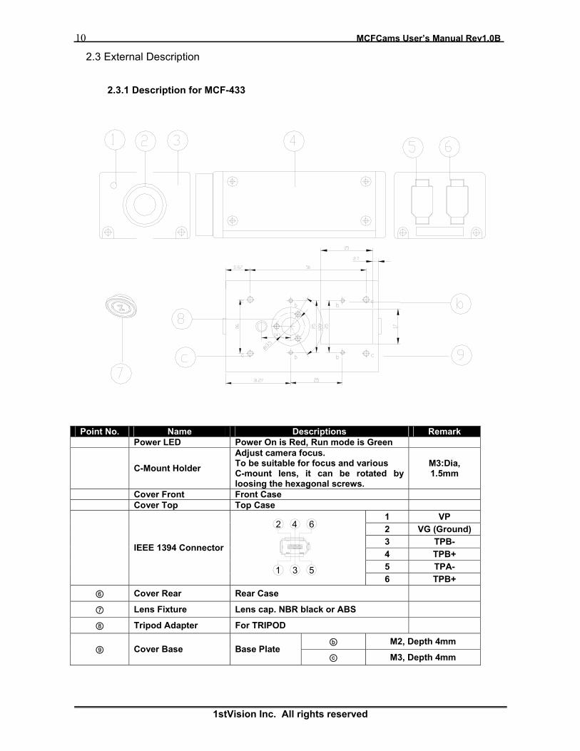
2.3 External Description
2.3.1 Description for MCF-433
Point No. Name Descriptions Remark � Power LED Power On is Red, Run mode is Green
� C-Mount Holder Adjust camera focus. To be suitable for focus and various C-mount lens, it can be rotated by loosing the hexagonal screws.
M3:Dia, 1.5mm
� Cover Front Front Case � Cover Top Top Case
1 VP 2 VG (Ground) 3 TPB- 4 TPB+ 5 TPA-
� IEEE 1394 Connector
6 TPB+ ⑥ Cover Rear Rear Case
⑦ Lens Fixture Lens cap. NBR black or ABS
⑧ Tripod Adapter For TRIPOD
ⓑ M2, Depth 4mm ⑨ Cover Base Base Plate
ⓒ M3, Depth 4mm
1
2
3
4
5
6

MCF Cams User’s Manual Rev1.0B 11
© 1stVision. All rights reserved
2.3.3 Description for All Trigger(FT/MT) Models
Point No. Name Descriptions Remark
� Lens Fixture Lens cap. NBR black or ABS
� Adapter Ring Adjust camera focus To be suitable for focus and various C- mount lens, it can be rotated by loosing the hexagonal screws.
M3:Dia, 1.5mm
� Lens Mount Ring Mounts adapter ring � Cover Front Front Case � Lens Mount Hole M3x3 : Dia 1.5mm � Camera Mount Hole M4x6, Depth 5mm � OLPF Optical Low Pass Filter Only Color � CCD sensor Sony Wfine CCD � Power LED Power On is Red, Run mode is Green � PCB Camera PCB set
1 VP 2 VG (Ground) 3 TPB- 4 TPB+ 5 TPA-
� IEEE 1394 Connector
6 TPB+ � Rubber packing NBR black � Cover Rear Rear Case
Pin Signal Pin Signal 1 Power GND 7 NC 2 +12V 8 GND 3 GND 9 NC
External Trigger Connector
4 NC 10 Ext. Trigger Camera Side: Hirose HR10A Series 5 GND 11 NC
�
Cable Side : HR10A-10P-12S 6 NC 12 GND
1
2
3
4
5
6

12 MCFCams User’s Manual Rev1.0B
1stVision Inc. All rights reserved
2.4 System Environment
MC-FCams works with other windows application such as “amcap.exe” in DirectX SDKTM, XP capture application in XP default, TWAIN interface, WDM stream an so on. the camera also works with all IIDC (formerly DCAM) compatible IEEE 1394 program and image processing libraries such as IMAQ and MIL 7.5 or higher.
2.4.1 System Requirements
� IEEE 1394 OHCI Card or PCMCIA adapter � Windows 2000 / XP � IEEE 1394 Cable with 6p-to-6p or 4p-to-6p � One or more MC-FCams Camera � DirectX 9.0 or higher In Windows XP Environment, we strongly recommend DirectX 9.0b or higher � Video Adapter supports 24bit color and 1280x1024 resolution or higher � CPU with 1.5GHz or more � 128MByte or more System Memory
2.4.2 Demo Application - ImCam
The Demo Application only works for the camera included MC-FCams driver. Please refer to the Demo Application Manual included in the downloaded SW(in Application Directory)
2.5 Multiple Camera Connections
If you have two or more IEEE 1394 cameras, you can connect these cameras to the PC simultaneously. In this situation, you can run cameras at the same time while you maintaining the total IEEE 1394 bandwidth for all cameras below the amount defined in IEEE 1394 specification. The bandwidth of a camera can be calculated by multiplexing the data bits of a format, image resolution and frame rates. For example if you run with 800x600 @fps resolution, the bandwidth is 800x600x16x15 = 115Mbps.
3. Camera Functions
3.1 IEEE1394 DCAM Spec 1.30
MC-F digital cameras fully support IIDC Specification 1.30 which describes the standard definition for IEEE 1394 compliant digital cameras. The recommend specification supplied by 1394TA(www.1394ta.org) defines camera registers, fields within those registers, video formats, modes of operation, and controls for each. Please refer to the IIDC Specification for detail register space.
3.2 Initialize You can initialize the camera to factory default state by writing “1” to the following register.
Address Name Field Bit Description
FFFF F0F0 0000 INITIALIZE Initialize 0 If assert this bit, Camera will re-set to initial (factory setting value) sate.

MCF Cams User’s Manual Rev1.0B 13
© 1stVision. All rights reserved
3.2.1 User Defined 1394 Address for CR on Power Reset
3.3 Brightness
The brightness of images can be controlled by changing the black level setting. Adjust the brightness if the appropriate gradation cannot be obtained due to the blurring of the black portions of the image.
Address Name Field Bit Description
Presence_Inq 0 Presence of this feature Abs_Control_Inq 1 Capability of control with absolute value - 2 Reserved
One_Push_Inq 3 One push auto mode(Controlled automatically by camera only once)
ReadOut_Inq 4 Capability of reading the value of this feature On/Off_Inq 5 Capability of switching this feature On and OFF Auto_Inq 6 Auto mode(Controlled automatically by camera) Manual_Inq 7 Manual mode(Controlled by user) Min_Value [8..19] Minimum value for this feature control
F0F0 0500
BRIGHTNESS_INQ
Max_Value [20..31] Maximum value for this feature control
Presence_Inq 0 Presence of this feature 0:N/A 1:Available
Abs_Control 1
Absolute value control 0: Control with value in the Value field 1: Control with value in the Absolute value CSR If this bit = 1, value in the Value field is ignored.
- [2..4] Reserved
One_Push 5
Write ‘1’ :begin to work(Self cleared after operation) Read: Value=’1’ in operation Value=’0’ not in operation If A_M_Mode =1, this bit is ignored
ON_OFF 6
Write: ON or OFF this feature, Read: read a status 0:OFF, 1:ON If this bit=0, other fields will be read only.
A_M_Mode 7 Write: set the mode, Read: read a current mode 0: Manual, 1:Auto
- [8..19] Reserved
F0F0 0800
BRIGHTNESS
Value [20..31]
Value. Write the value in Auto mode, this filed is ignored. If “ReadOut” capability is not available, read value Has no meaning
Address Description Read/Write
0xF2F10100
(Only for FT/MT Models)
Power on reset condition control register If bit value is 1, the current register value is saved as default or reset value. (Self cleared)
At the next power on, this saving value is default/reset value. Bit 0 : Auto Exposure Bit 1 : Shutter Speed Bit 2 : Gain Bit 3 : Brightness Bit 4 : Sharpness Bit 5 : Gamma Bit 19 ~ Bit 6 : Reserved Bit 20 : Auto shutter-speed maximum/minimum value register Bit 21 : Auto gain maximum/minimum value register Bit 22 : Trigger control register Bit 23 : Strobe control register
Read/Write

14 MCFCams User’s Manual Rev1.0B
1stVision Inc. All rights reserved
3.4 Sharpness
3.4.1 F-Models
The sharpness procedure may be used to compensate low-pass effects caused for instance by the spatial color interpolation. If you prefer not to apply this kind of signal manipulation you should switch it off.
3.4.2 FT/MT-Models
Increase or decrease contrast. Increasing contrast increases the apparent difference in lightness between lighter and darker pixels. For FT/MT cameras, Contrast is mapping in feature
Address Name Field Bit Description
Presence_Inq 0 Presence of this feature Abs_Control_Inq 1 Capability of control with absolute value - 2 Reserved
One_Push_Inq 3 One push auto mode(Controlled automatically by camera only once)
ReadOut_Inq 4 Capability of reading the value of this feature
On/Off_Inq 5 Capability of switching this feature On and OFF
Auto_Inq 6 Auto mode(Controlled automatically by camera)
Manual_Inq 7 Manual mode(Controlled by user) Min_Value [8..19] Minimum value for this feature control
F0F0 0508 SHARPNESS_INQ
Max_Value [20..31] Maximum value for this feature control
Presence_Inq 0 Presence of this feature 0:N/A 1:Available
Abs_Control 1
Absolute value control 0: Control with value in the Value field 1: Control with value in the Absolute value CSR If this bit = 1, value in the Value field is ignored.
- [2..4] Reserved
One_Push 5
Write ‘1’ :begin to work(Self cleared after operation) Read: Value=’1’ in operation Value=’0’ not in operation If A_M_Mode =1, this bit is ignored
ON_OFF 6
Write: ON or OFF this feature, Read: read a status 0:OFF, 1:ON If this bit=0, other fields will be read only.
A_M_Mode 7 Write: set the mode, Read: read a current mode 0: Manual, 1:Auto
- [8..19] Reserved
F0F0 0808 SHARPNESS
Value [20..31]
Value. Write the value in Auto mode, this filed is ignored. If “ReadOut” capability is not available, read value Has no meaning
MCF Cams User’s Manual Rev1.0B 15
© 1stVision. All rights reserved
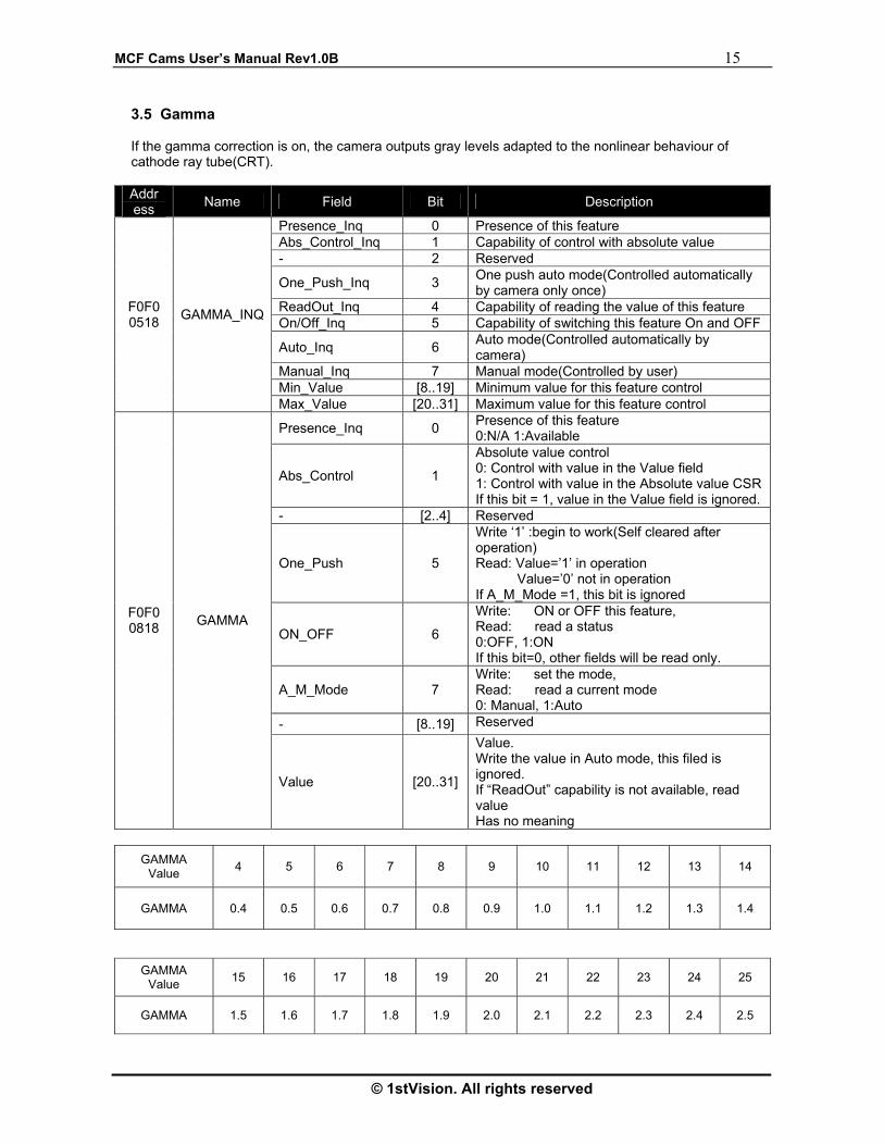
3.5 Gamma
If the gamma correction is on, the camera outputs gray levels adapted to the nonlinear behaviour of cathode ray tube(CRT).
GAMMA
Value 4 5 6 7 8 9 10 11 12 13 14
GAMMA 0.4 0.5 0.6 0.7 0.8 0.9 1.0 1.1 1.2 1.3 1.4
GAMMA Value 15 16 17 18 19 20 21 22 23 24 25
GAMMA 1.5 1.6 1.7 1.8 1.9 2.0 2.1 2.2 2.3 2.4 2.5
Addr ess Name Field Bit Description
Presence_Inq 0 Presence of this feature Abs_Control_Inq 1 Capability of control with absolute value - 2 Reserved
One_Push_Inq 3 One push auto mode(Controlled automatically by camera only once)
ReadOut_Inq 4 Capability of reading the value of this feature On/Off_Inq 5 Capability of switching this feature On and OFF
Auto_Inq 6 Auto mode(Controlled automatically by camera)
Manual_Inq 7 Manual mode(Controlled by user) Min_Value [8..19] Minimum value for this feature control
F0F0 0518 GAMMA_INQ
Max_Value [20..31] Maximum value for this feature control
Presence_Inq 0 Presence of this feature 0:N/A 1:Available
Abs_Control 1
Absolute value control 0: Control with value in the Value field 1: Control with value in the Absolute value CSR If this bit = 1, value in the Value field is ignored.
- [2..4] Reserved
One_Push 5
Write ‘1’ :begin to work(Self cleared after operation) Read: Value=’1’ in operation Value=’0’ not in operation If A_M_Mode =1, this bit is ignored
ON_OFF 6
Write: ON or OFF this feature, Read: read a status 0:OFF, 1:ON If this bit=0, other fields will be read only.
A_M_Mode 7 Write: set the mode, Read: read a current mode 0: Manual, 1:Auto
- [8..19] Reserved
F0F0 0818 GAMMA
Value [20..31]
Value. Write the value in Auto mode, this filed is ignored. If “ReadOut” capability is not available, read value Has no meaning

16 MCFCams User’s Manual Rev1.0B
1stVision Inc. All rights reserved
3.6 Saturation
The saturation control allows you to manually adjust the level of color in the digital image from zero (black and white) to many colors. If you prefer not to apply this kind of signal manipulation, you can switch it off. The saturation is applied only to F-Models such as MCF-433.
Address Name Field Bit Description Presence_Inq 0 Presence of this feature Abs_Control_Inq 1 Capability of control with absolute value - 2 Reserved
One_Push_Inq 3 One push auto mode(Controlled automatically by camera only once)
ReadOut_Inq 4 Capability of reading the value of this feature On/Off_Inq 5 Capability of switching this feature On and OFF Auto_Inq 6 Auto mode(Controlled automatically by camera) Manual_Inq 7 Manual mode(Controlled by user) Min_Value [8..19] Minimum value for this feature control
F0F0 0514
SATURATION_INQ
Max_Value [20..31] Maximum value for this feature control
Presence_Inq 0 Presence of this feature 0:N/A 1:Available
Abs_Control 1
Absolute value control 0: Control with value in the Value field 1: Control with value in the Absolute value CSR If this bit = 1, value in the Value field is ignored.
- [2..4] Reserved
One_Push 5
Write ‘1’ :begin to work(Self cleared after operation) Read: Value=’1’ in operation Value=’0’ not in operation If A_M_Mode =1, this bit is ignored
ON_OFF 6
Write: ON or OFF this feature, Read: read a status 0:OFF, 1:ON If this bit=0, other fields will be read only.
A_M_Mode 7 Write: set the mode, Read: read a current mode 0: Manual, 1:Auto
- [8..19] Reserved
F0F0 0814
SATURATION
Value [20..31]
Value. Write the value in Auto mode, this filed is ignored. If “ReadOut” capability is not available, read value Has no meaning
MCF Cams User’s Manual Rev1.0B 17
© 1stVision. All rights reserved
3.7 White Balance
U/R(red/green) and V/B(green/blue) controls alter the degree to which red and blue CCD component pixels are weighted to form composite pixels. White balance can be controlled manually or automatically. In manual mode, you can change both parameters. This helps you to initially set the camera as quickly as possible. Some adjustment may be necessary, depending on current illumination. For this purpose, parameter changing has to be inactive. The automatic white balance feature offers two operation modes. If “Auto” is checked, the balancing algorithms affect the video stream continuously. Furthermore, the “One Push” white balance option can be used for a one-push (non-iterative) calibration of the white balance values. However, if you prefer not to apply this kind of signal manipulation at all, you can switch if off. The White Balance is applied only to F-Models such as MCF-433.
Address Name Field Bit Description Presence_Inq 0 Presence of this feature Abs_Control_Inq 1 Capability of control with absolute value - 2 Reserved
One_Push_Inq 3 One push auto mode(Controlled automatically by camera only once)
ReadOut_Inq 4 Capability of reading the value of this feature On/Off_Inq 5 Capability of switching this feature On and OFF Auto_Inq 6 Auto mode(Controlled automatically by camera) Manual_Inq 7 Manual mode(Controlled by user) Min_Value [8..19] Minimum value for this feature control
F0F0 050C
WHITE_BAL_I
NQ
Max_Value [20..31] Maximum value for this feature control Presence_Inq 0 Presence of this feature. 0:N/A 1:Available
Abs_Control 1
Absolute value control 0: Control with value in the Value field 1: Control with value in the Absolute value CSR If this bit = 1, value in the Value field is ignored.
- [2..4] Reserved
One_Push 5
Write ‘1’ :begin to work(Self cleared after operation) Read: Value=’1’ in operation Value=’0’ not in operation If A_M_Mode =1, this bit is ignored
ON_OFF 6
Write: ON or OFF this feature, Read: read a status 0:OFF, 1:ON If this bit=0, other fields will be read only.
A_M_Mode 7 Write: set the mode, Read: read a current mode 0: Manual, 1:Auto
U/B_Value [8..19]
U Value / B_Value. Write the value in AUTO mode, this field is ignored. If “ReadOut” capability is not available,, read value has no mean
F0F0 080C
WHITE_BALANCE
V/R_Value [20..31]
V Value / R_Value Write the value in AUTO mode, this field is ignored. If”ReadOut” capability is not available, read value has no mean

18 MCFCams User’s Manual Rev1.0B
1stVision Inc. All rights reserved
3.8 Shutter
The shutter control allows the CCD image integration time to be set. This parameter can be configured manually or automatically (together with gain) using an internal feedback loop.
Address Name Field Bit Description Presence_Inq 0 Presence of this feature Abs_Control_Inq 1 Capability of control with absolute value - 2 Reserved
One_Push_Inq 3 One push auto mode(Controlled automatically by camera only once)
ReadOut_Inq 4 Capability of reading the value of this feature On/Off_Inq 5 Capability of switching this feature On and OFF Auto_Inq 6 Auto mode(Controlled automatically by camera) Manual_Inq 7 Manual mode(Controlled by user) Min_Value [8..19] Minimum value for this feature control
F0F0 051C
SHUTTER_INQ
Max_Value [20..31] Maximum value for this feature control
Presence_Inq 0 Presence of this feature 0:N/A 1:Available
Abs_Control 1
Absolute value control 0: Control with value in the Value field 1: Control with value in the Absolute value CSR If this bit = 1, value in the Value field is ignored.
- [2..4] Reserved
One_Push 5
Write ‘1’ :begin to work(Self cleared after operation) Read: Value=’1’ in operation Value=’0’ not in operation If A_M_Mode =1, this bit is ignored
ON_OFF 6
Write: ON or OFF this feature, Read: read a status 0:OFF, 1:ON If this bit=0, other fields will be read only.
A_M_Mode 7 Write: set the mode, Read: read a current mode 0: Manual, 1:Auto
- [8..19] Reserved
F0F0 081C SHUTTER
Value [20..31]
Value. Write the value in Auto mode, this filed is ignored. If “ReadOut” capability is not available, read value Has no meaning
MCF Cams User’s Manual Rev1.0B 19
© 1stVision. All rights reserved
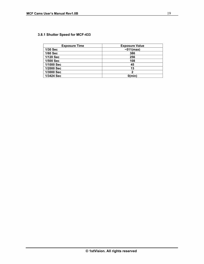
3.8.1 Shutter Speed for MCF-433
Exposure Time Exposure Value 1/30 Sec ~511(max) 1/60 Sec 386 1/120 Sec 256 1/500 Sec 108 1/1000 Sec 45 1/2000 Sec 13 1/3000 Sec 2 1/3424 Sec 0(min)

20 MCFCams User’s Manual Rev1.0B
1stVision Inc. All rights reserved
3.8.4 Shutter Speed for All Trigger Cameras
3.8.5 User Defined 1394 Address for Auto Shutter Speed
Address Description Read/Write
0xF2F10004
(Only for FT/MT Models)
Auto shutter-speed maximum/minimum value register.*(32bit) At auto shutter mode, shutter speed value is checked between auto shutter-speed maximum value and minimum value.
Read/Write
Range Exposure Time
47s ~ 65s T= (Y-3304)*1000+46000 ms 1s 3305~3323 5.9s ~ 46s T= (Y-2902)*100+5800 ms 100ms 2903~3304 780ms ~ 5800ms T= (Y-2399)*10+770 ms 10ms 2400~2902 77ms ~ 770ms T= (Y-1705)+76 ms 1ms 1706 ~ 2399 5.6ms ~ 76ms T= (Y-1000)*100+5500 us 100us 1001~1705 510us ~ 5500us T= (Y-500)*10+500 us 10us 501~1000 1us ~ 500us T= Y us 1us 1~500
Shutter Speed Time : T Increment Step
1394 Shutter Value (Y)
Example Shutter Speed Table
500ms 2129 100us 100
200ms 1829 10us 10
100ms 1729 1us 1
2822 2ms 650
2s 2522 1ms
1s 2422 500us 500
5ms 950
65s 3323 50ms 1445
60s 20ms
20s 10ms 1045
Exposure Time 1394 Shutter Exposure Time 1394 Shutter
Auto shutter-speed Maximum value
31 16 15 0
Auto shutter-speed Minimum value
MCF Cams User’s Manual Rev1.0B 21
© 1stVision. All rights reserved
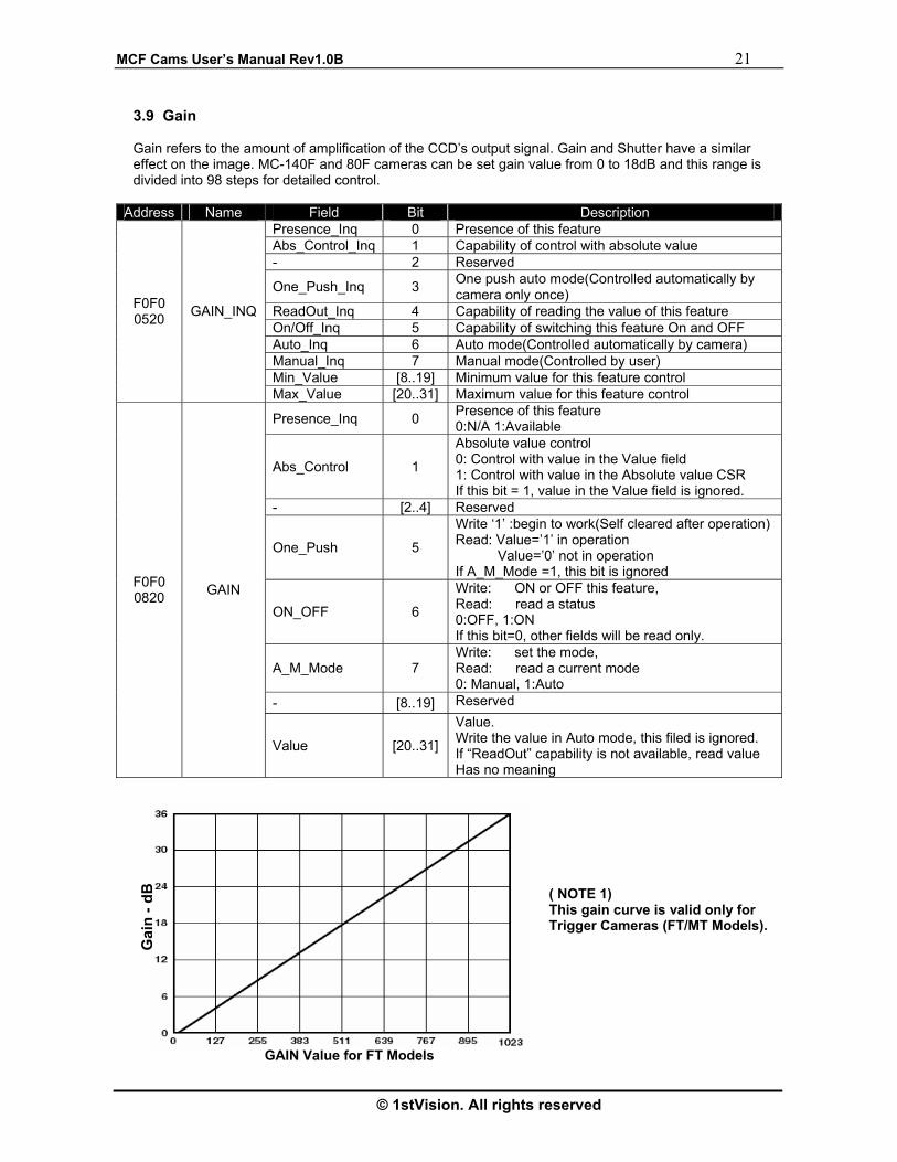
3.9 Gain
Gain refers to the amount of amplification of the CCD’s output signal. Gain and Shutter have a similar effect on the image. MC-140F and 80F cameras can be set gain value from 0 to 18dB and this range is divided into 98 steps for detailed control.
Address Name Field Bit Description
Presence_Inq 0 Presence of this feature Abs_Control_Inq 1 Capability of control with absolute value - 2 Reserved
One_Push_Inq 3 One push auto mode(Controlled automatically by camera only once)
ReadOut_Inq 4 Capability of reading the value of this feature On/Off_Inq 5 Capability of switching this feature On and OFF Auto_Inq 6 Auto mode(Controlled automatically by camera) Manual_Inq 7 Manual mode(Controlled by user) Min_Value [8..19] Minimum value for this feature control
F0F0 0520 GAIN_INQ
Max_Value [20..31] Maximum value for this feature control
Presence_Inq 0 Presence of this feature 0:N/A 1:Available
Abs_Control 1
Absolute value control 0: Control with value in the Value field 1: Control with value in the Absolute value CSR If this bit = 1, value in the Value field is ignored.
- [2..4] Reserved
One_Push 5
Write ‘1’ :begin to work(Self cleared after operation) Read: Value=’1’ in operation Value=’0’ not in operation If A_M_Mode =1, this bit is ignored
ON_OFF 6
Write: ON or OFF this feature, Read: read a status 0:OFF, 1:ON If this bit=0, other fields will be read only.
A_M_Mode 7 Write: set the mode, Read: read a current mode 0: Manual, 1:Auto
- [8..19] Reserved
F0F0 0820 GAIN
Value [20..31]
Value. Write the value in Auto mode, this filed is ignored. If “ReadOut” capability is not available, read value Has no meaning
( NOTE 1)This gain curve is valid only for Trigger Cameras (FT/MT Models).
GAIN Value for FT Models
Gai
n - d
B

22 MCFCams User’s Manual Rev1.0B
1stVision Inc. All rights reserved
3.9.1 User Defined Address for Auto Gain only for FT/MT Models
Address Description Read/Write
0xF2F10000 A/D bit resolution Bit 3~Bit0 : A/D bit resolution Read only
0xF2F10008
Auto gain maximum/minimum value register.*(32bit) At auto gain mode, gain value is checked between auto gain maximum value and minimum value.
Read/Write
3.10 Auto Exposure
The automatic shutter/gain mode is based on a feedback loop which calculates the average pixel luminance. This average is then compared with the exposure reference value, adjusting shutter and gain accordingly. As of now, for the cameras, Auto Exposure value is used as the main value to AE algorithm.
Address Name Field Bit Description
Presence_Inq 0 Presence of this feature Abs_Control_Inq 1 Capability of control with absolute value - 2 Reserved
One_Push_Inq 3 One push auto mode(Controlled automatically by camera only once)
ReadOut_Inq 4 Capability of reading the value of this feature On/Off_Inq 5 Capability of switching this feature On and OFF Auto_Inq 6 Auto mode(Controlled automatically by camera) Manual_Inq 7 Manual mode(Controlled by user) Min_Value [8..19] Minimum value for this feature control
F0F0 0504
AUTO_EXPOSURE_INQ
Max_Value [20..31] Maximum value for this feature control
Presence_Inq 0 Presence of this feature 0:N/A 1:Available
Abs_Control 1
Absolute value control 0: Control with value in the Value field 1: Control with value in the Absolute value CSR If this bit = 1, value in the Value field is ignored.
- [2..4] Reserved
One_Push 5
Write ‘1’ :begin to work(Self cleared after operation) Read: Value=’1’ in operation Value=’0’ not in operation If A_M_Mode =1, this bit is ignored
ON_OFF 6
Write: ON or OFF this feature, Read: read a status 0:OFF, 1:ON If this bit=0, other fields will be read only.
A_M_Mode 7 Write: set the mode, Read: read a current mode 0: Manual, 1:Auto
- [8..19] Reserved
F0F0 0804
AUTO_EXPOSURE
Value [20..31]
Value. Write the value in Auto mode, this filed is ignored. If “ReadOut” capability is not available, read value Has no meaning
Auto gain Maximum value
31 16 15 0
Auto gain Minimum value
MCF Cams User’s Manual Rev1.0B 23
© 1stVision. All rights reserved
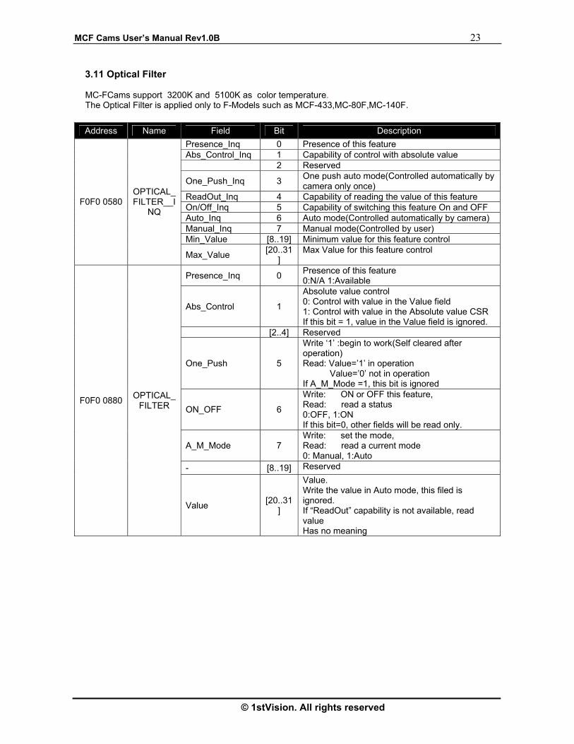
3.11 Optical Filter MC-FCams support 3200K and 5100K as color temperature. The Optical Filter is applied only to F-Models such as MCF-433,MC-80F,MC-140F.
Address Name Field Bit Description Presence_Inq 0 Presence of this feature Abs_Control_Inq 1 Capability of control with absolute value 2 Reserved
One_Push_Inq 3 One push auto mode(Controlled automatically by camera only once)
ReadOut_Inq 4 Capability of reading the value of this feature On/Off_Inq 5 Capability of switching this feature On and OFF Auto_Inq 6 Auto mode(Controlled automatically by camera) Manual_Inq 7 Manual mode(Controlled by user) Min_Value [8..19] Minimum value for this feature control
F0F0 0580 OPTICAL_FILTER__I
NQ
Max_Value [20..31]
Max Value for this feature control
Presence_Inq 0 Presence of this feature 0:N/A 1:Available
Abs_Control 1
Absolute value control 0: Control with value in the Value field 1: Control with value in the Absolute value CSR If this bit = 1, value in the Value field is ignored.
[2..4] Reserved
One_Push 5
Write ‘1’ :begin to work(Self cleared after operation) Read: Value=’1’ in operation Value=’0’ not in operation If A_M_Mode =1, this bit is ignored
ON_OFF 6
Write: ON or OFF this feature, Read: read a status 0:OFF, 1:ON If this bit=0, other fields will be read only.
A_M_Mode 7 Write: set the mode, Read: read a current mode 0: Manual, 1:Auto
- [8..19] Reserved
F0F0 0880 OPTICAL_FILTER
Value [20..31]
Value. Write the value in Auto mode, this filed is ignored. If “ReadOut” capability is not available, read value Has no meaning
24 MCFCams User’s Manual Rev1.0B
1stVision Inc. All rights reserved
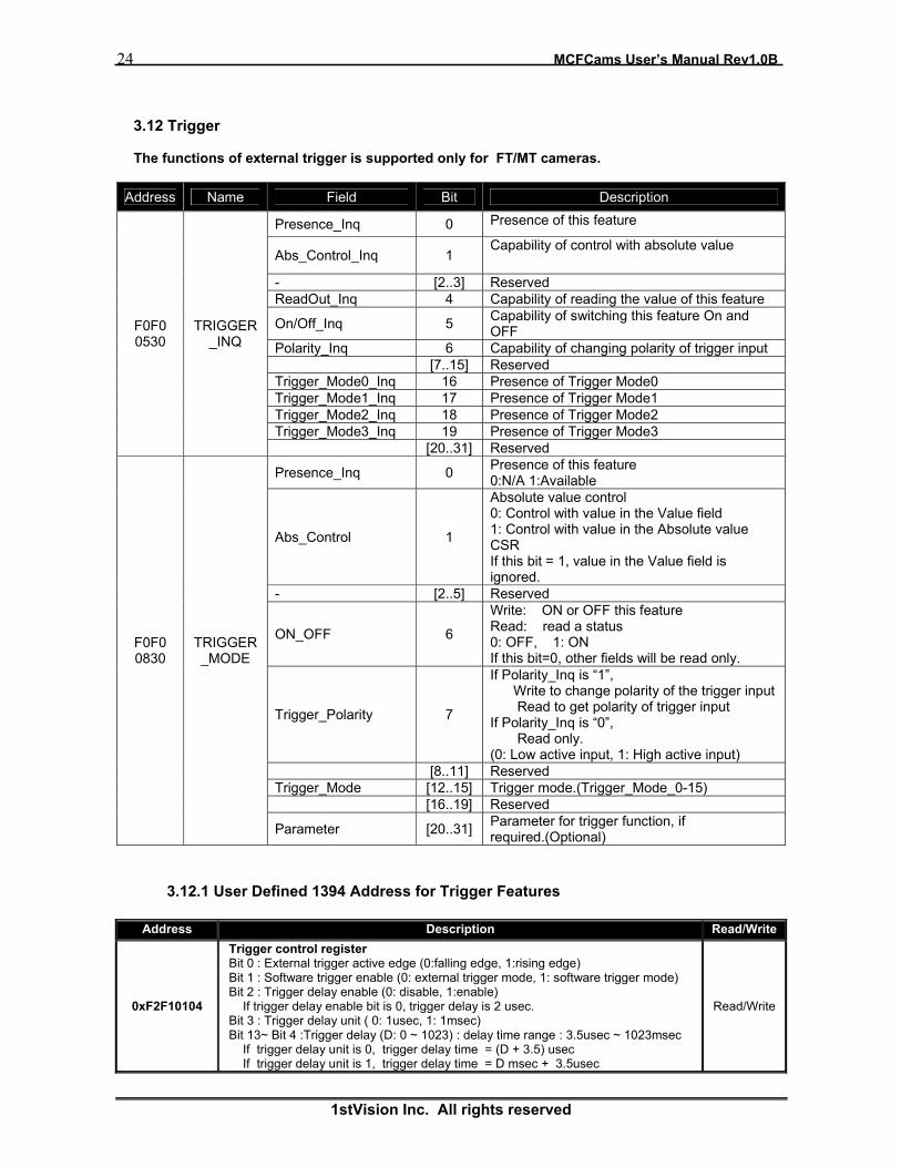
3.12 Trigger The functions of external trigger is supported only for FT/MT cameras.
Address Name Field Bit Description
Presence_Inq 0 Presence of this feature
Abs_Control_Inq 1 Capability of control with absolute value
- [2..3] Reserved ReadOut_Inq 4 Capability of reading the value of this feature
On/Off_Inq 5 Capability of switching this feature On and OFF
Polarity_Inq 6 Capability of changing polarity of trigger input [7..15] Reserved Trigger_Mode0_Inq 16 Presence of Trigger Mode0 Trigger_Mode1_Inq 17 Presence of Trigger Mode1 Trigger_Mode2_Inq 18 Presence of Trigger Mode2 Trigger_Mode3_Inq 19 Presence of Trigger Mode3
F0F0 0530
TRIGGER_INQ
[20..31] Reserved
Presence_Inq 0 Presence of this feature 0:N/A 1:Available
Abs_Control 1
Absolute value control 0: Control with value in the Value field 1: Control with value in the Absolute value CSR If this bit = 1, value in the Value field is ignored.
- [2..5] Reserved
ON_OFF 6
Write: ON or OFF this feature Read: read a status 0: OFF, 1: ON If this bit=0, other fields will be read only.
Trigger_Polarity 7
If Polarity_Inq is “1”, Write to change polarity of the trigger input Read to get polarity of trigger input If Polarity_Inq is “0”, Read only. (0: Low active input, 1: High active input)
[8..11] Reserved Trigger_Mode [12..15] Trigger mode.(Trigger_Mode_0-15) [16..19] Reserved
F0F0 0830
TRIGGER_MODE
Parameter [20..31] Parameter for trigger function, if required.(Optional)
3.12.1 User Defined 1394 Address for Trigger Features
Address Description Read/Write
0xF2F10104
Trigger control register Bit 0 : External trigger active edge (0:falling edge, 1:rising edge) Bit 1 : Software trigger enable (0: external trigger mode, 1: software trigger mode) Bit 2 : Trigger delay enable (0: disable, 1:enable) If trigger delay enable bit is 0, trigger delay is 2 usec. Bit 3 : Trigger delay unit ( 0: 1usec, 1: 1msec) Bit 13~ Bit 4 :Trigger delay (D: 0 ~ 1023) : delay time range : 3.5usec ~ 1023msec If trigger delay unit is 0, trigger delay time = (D + 3.5) usec If trigger delay unit is 1, trigger delay time = D msec + 3.5usec
Read/Write

MCF Cams User’s Manual Rev1.0B 25
© 1stVision. All rights reserved
3.12.2 Electrical Specification for Ext. Trigger and Strobe signal
3.12.3 Trigger & Strobe signal relation
Address Description Read/Write
0xF2F10108 Software trigger Whenever this address is accessed, one trigger pulse is generated. The read value means software trigger count from starting time of trigger mode
Read Only
0xF2F1010C
Strobe Control Register. Bit 0 : Strobe enable ( 0: disable, 1: enable) Bit 1 : Strobe active ( 0: active low, 1: active high) Bit 2 : Strobe delay unit ( 0: 1usec, 1: 250usec) Bit 3 : Strobe pulse width unit ( 0: 1usec, 1: 250usec) Bit 13 ~ Bit 4 : Strobe delay (D: 0 ~ 1023) : delay time range : 1usec ~ 255msec If strobe delay unit is 0, strobe delay time = (D + 0.3) usec If strobe delay unit is 1, strobe delay time = (D * 250) usec Bit 23 ~ Bit 16 : Strobe pulse width (D: 0 ~ 255) : width range : 1usec ~ 64msec If strobe pulse width unit is 0, strobe duration time = (D+1) usec If strobe pulse width unit is 1, strobe duration time = (D+1)*250 usec
Read/Write
3V ~ 5V, or Open (internally 5V pull up)
Must be greater than 70nsec
Strobe
4V ~ 5V
2usec ~ 255msec User can set strobe duration
Ext. Trigger
External Trigger or
Software Trigger
Trigger delay
Active Trigger
Exposure time
Shutter
Strobe delay Strobe
Strobe pulse width

26 MCFCams User’s Manual Rev1.0B
1stVision Inc. All rights reserved
3.12.4 Trigger Timing Diagram
1VD =16.7msec : VD is frame
MC-F333MT Trigger Timing Diagram
If 60 fps, 1 VD. If 30 fps, 2 VD. If 15 fps, 4 VD. If 7.5 fps, 8 VD If 3.75 fps, 16 VD If 1.875 fps, 32 VD
If 60 fps, 1 VD. If 30 fps, 2 VD. If 15 fps, 4 VD. If 7.5 fps, 8 VD If 3.75 fps, 16 VD If 1.875 fps,32 VD
Shutter Speed Time (1us~65s)
Store Zone(1VD
Next Trigger Prohibit
Invalid valid
Ext. Trigge
Shutte
1394 data transfer zone
> 70ns
dela= about
MCF Cams User’s Manual Rev1.0B 27
© 1stVision. All rights reserved
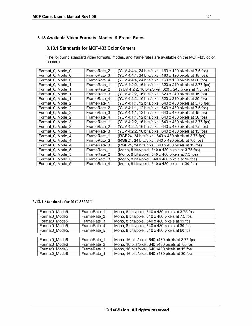
3.13 Available Video Formats, Modes, & Frame Rates
3.13.1 Standards for MCF-433 Color Camera The following standard video formats, modes, and frame rates are available on the MCF-433 color camera
3.13.4 Standards for MC-333MT
Format_0, Mode_0 FrameRate_2 (YUV 4:4:4, 24 bits/pixel, 160 x 120 pixels at 7.5 fps) Format_0, Mode_0 FrameRate_3 (YUV 4:4:4, 24 bits/pixel, 160 x 120 pixels at 15 fps); Format_0, Mode_0 FrameRate_4 (YUV 4:4:4, 24 bits/pixel, 160 x 120 pixels at 30 fps) Format_0, Mode_1 FrameRate_1 (YUV 4:2:2, 16 bits/pixel, 320 x 240 pixels at 3.75 fps) Format_0, Mode_1 FrameRate_2 (YUV 4:2:2, 16 bits/pixel, 320 x 240 pixels at 7.5 fps) Format_0, Mode_1 FrameRate_3 (YUV 4:2:2, 16 bits/pixel, 320 x 240 pixels at 15 fps) Format_0, Mode_1 FrameRate_4 (YUV 4:2:2, 16 bits/pixel, 320 x 240 pixels at 30 fps) Format_0, Mode_2 FrameRate_1 (YUV 4:1:1, 12 bits/pixel, 640 x 480 pixels at 3.75 fps) Format_0, Mode_2 FrameRate_2 (YUV 4:1:1, 12 bits/pixel, 640 x 480 pixels at 7.5 fps) Format_0, Mode_2 FrameRate_3 (YUV 4:1:1, 12 bits/pixel, 640 x 480 pixels at 15 fps) Format_0, Mode_2 FrameRate_4 (YUV 4:1:1, 12 bits/pixel, 640 x 480 pixels at 30 fps) Format_0, Mode_3 FrameRate_1 (YUV 4:2:2, 16 bits/pixel, 640 x 480 pixels at 3.75 fps) Format_0, Mode_3 FrameRate_2 (YUV 4:2:2, 16 bits/pixel, 640 x 480 pixels at 7.5 fps) Format_0, Mode_3 FrameRate_3 (YUV 4:2:2, 16 bits/pixel, 640 x 480 pixels at 15 fps) Format_0, Mode_4 FrameRate_1 (RGB24, 24 bits/pixel, 640 x 480 pixels at 3.75 fps) Format_0, Mode_4 FrameRate_2 (RGB24, 24 bits/pixel, 640 x 480 pixels at 7.5 fps) Format_0, Mode_4 FrameRate_3 (RGB24, 24 bits/pixel, 640 x 480 pixels at 15 fps) Format_0, Mode_5 FrameRate_1 (Mono, 8 bits/pixel, 640 x 480 pixels at 3.75 fps) Format_0, Mode_5 FrameRate_2 (Mono, 8 bits/pixel, 640 x 480 pixels at 7.5 fps) Format_0, Mode_5 FrameRate_3 (Mono, 8 bits/pixel, 640 x 480 pixels at 15 fps) Format_0, Mode_5 FrameRate_4 (Mono, 8 bits/pixel, 640 x 480 pixels at 30 fps)
Format0_Mode5 FrameRate_1 Mono, 8 bits/pixel, 640 x 480 pixels at 3.75 fps Format0_Mode5 FrameRate_2 Mono, 8 bits/pixel, 640 x 480 pixels at 7.5 fps Format0_Mode5 FrameRate_3 Mono, 8 bits/pixel, 640 x 480 pixels at 15 fps Format0_Mode5 FrameRate_4 Mono, 8 bits/pixel, 640 x 480 pixels at 30 fps Format0_Mode5, FrameRate_5 Mono, 8 bits/pixel, 640 x 480 pixels at 60 fps * Format0_Mode6 FrameRate_1 Mono, 16 bits/pixel, 640 x480 pixels at 3.75 fps Format0_Mode6 FrameRate_2 Mono, 16 bits/pixel, 640 x480 pixels at 7.5 fps Format0_Mode6 FrameRate_3 Mono, 16 bits/pixel, 640 x480 pixels at 15 fps Format0_Mode6 FrameRate_4 Mono, 16 bits/pixel, 640 x480 pixels at 30 fps

28 MCFCams User’s Manual Rev1.0B
1stVision Inc. All rights reserved
3.14 Output Data Format for color cameras
The data format of color cameras is outputting as Bayer RGB data format and the form of the data transmitted from is as follows.

MCF Cams User’s Manual Rev1.0B 29
© 1stVision. All rights reserved
4. Camera Dimensions
4.1 MCF-433
BLANK

30 MCFCams User’s Manual Rev1.0B
1stVision Inc. All rights reserved
.
4.3 Trigger Models : MC-FyyyX ( x = B/W or Color, yyy = Resoltion Size)
2
1
4 6
53

MCF Cams User’s Manual Rev1.0B 31
© 1stVision. All rights reserved
5. Troubleshooting
5.1 Fault Checking Using the Camera LED
5.1.1 Fault Checking Using the Camera LED When you connect the camera with the PC through the IEEE 1394 cable, the LED in the back panel of the camera should be switched to Red color. If you cannot see this color, check the following items: • Check the OHCI card driver is installed properly
• Check the OHCI card driver is installed by clicking the right button on the “MyComputer” and select “Property”. When the property window shown, select “Hardware” tab and select “Device Manager” button at the page. In this dialog you can check whether the card driver is installed correctly or not like as follows.
• Check the IEEE 1394 Cable is working
5.1.2 Green LED
When you run the camera, the LED in the back panel should turn into green color. If the LED doesn’t change the color, camera may not be working properly and you may not receive the camera data. In this situation, plug off the camera after exiting application and re-connect the camera and run again. If you cannot see green color still, contact the technical support.
5.2 Error Messages while running the DEMO Application
5.2.1 “Can not Find the 1394 Camera”
If the dialog saying that “Con not Find the 1394 Camera” when you run the demo application, check the device driver for camera is installed properly. You can check the device driver by clicking the right button of the mouse on the “MyComputer” and selecting the “Property”. When the property dialog shown, select the “Hardware” tab and push the “Device Manager” button. In this dialog you should see “imaging device” list item, and you can see the camera lists if you expand the “image device” item like as follows. .

32 MCFCams User’s Manual Rev1.0B
1stVision Inc. All rights reserved
.
5.2.2 “Can not Find the 1394 The following information can help you solve problems that may occur during the setup of your camera. Make sure that the camera is part of the entire acquisition system. You may have to troubleshoot any or all of the following.
• Power supplies • cabling • Framegrabbers H/W and S/W • host computer
• light source • optics • operation environment
5.2.3 Common Solutions
The first step in troubleshooting is verify that your camera has all the correct connections regarding Power supply, Data cables, etc.
6. Technical Support Information
For technical assistance, contact 1stVision Support or Application Engineer.
Phone : 978-474-0044 Fax : 978-623-7260 Email : [email protected]