mc90-iii-user manual simulator kongsberg
TRANSCRIPT
Kongsberg Maritime Doc.no.: SO-0622-H1 / 2-May-05
ERS-L11 MAN B&W 5L90MC-VLCC Ver.MC90-III User's Manual
Engine Room Simulator
ERS-L11 MAN B&W-5L90MC-VLCC Version MC90-III
User’s Manual
Department/Author: Approved by: Arild Hermansen (s) Harald Kluken (s)
© 2005 Kongsberg Maritime AS All rights reserved
No part of this work covered by the copyright hereon may be reproduced or otherwise copied
without prior permission from Kongsberg Maritime AS

Kongsberg Maritime Doc.no.: SO-0622-H1 / 2-May-05
ERS-L11 MAN B&W 5L90MC-VLCC Ver.MC90-III User's Manual i
DOCUMENT STATUS Issue No. Date/Year Inc. by Issue No. Date/Year Inc. by SO-0622-A 11-Mar-97 VBJ/beba H 4-Oct-04 HD/beba SO-0622-B 15-Jul-97 AHE/beba H1 2-May-05 AHE/beba SO-0622-C 4-May-99 AHE/beba SO-0622-D 3-May-00 AHE/BEBA SO-0622-D1 24-Sep-02 HK/beba SO-0622-E 28-Jan-03 AHE/beba SO-0622-F 24-Mar-03 AHE/beba SO-0622-G 10-Jun-03 AHE/beba
CHANGES IN DOCUMENT
Issue ECO Paragraph Paragraph Heading/ No. No. No. Description of Change A First issue Supercedes Doc.no.TSO-0001-A/01-Jun-96 Chapter 4: Upgraded PowerChief & Steam
Plant Chapter 5: Upgraded pictures. B MP-1098 All General updating and correction of text. Added new chapter of Inert Gas Plant. Major changes in chapter 4 & 5. C MP-1287 New layout in document. Changes in
chapter 4 & 5 and Trip Codes. New pictures.D MP-1347 Minor changes in text and diagram ch.4.5.10
and 5.3.10 Minor changes in text 4.5.32 and 5.3.30. Removed 5.3.22
Added start/stop of Fire pumps from Mimic diagram 111, 4.5.24 and 5.3.45
4.5.23 and 5.3.26 (steering Gear) is new D1 All Changed logo, company name and title. E MP-1438 Added new
chapters; 4.5.8, 4.5.29, 4.5.34, 4.5.46
Added new chapters, 4.5.8, 4.5.29, 4.5.34, 4.5.46 to comply with release 3.9.
F MP-1450 Added ch.4.5.39
Added ch. 4.5.39 Fresh Water Sanitary System.
G MP-1452 Ch. 4.5.37, 5.3.32, 4.5.4 & 5.3.6
Manual updated to comply with release 3.10.
H MP-1516 All Upgraded to latest version. Reorganised User Manual, removed ch. 1, 2 & 3.
H1 1.3.47.1 Removed 2.7-2.10 under CO2 Alarm.
Kongsberg Maritime Doc.no.: SO-0622-H1 / 2-May-05
ii ERS-L11 MAN B&W 5L90MC-VLCC Ver.MC90-III User's Manual
TABLE OF CONTENTS
SECTION .................................................................................PAGE
1 FUNCTIONAL DESCRIPTION............................................... 1-1 1.1 Introduction ................................................................ 1-1 1.1.1 Main Engine Data ......................................................... 1-3 1.2 Engine Control Room (ECR) ........................................... 1-4 1.2.1 ME Remote Control (AutoChief) ...................................... 1-4 1.2.2 Main Switchboard (HW, if present).................................1-38 1.3 Engine Room Systems..................................................1-49 1.3.1 General Information ....................................................1-49 1.3.2 Shore Power ...............................................................1-50 1.3.3 Sea Water System.......................................................1-52 1.3.4 Fresh Water System ....................................................1-54 1.3.5 Start Air and Air Compressors .......................................1-56 1.3.6 Diesel Engine Driven Generator no. 1 and 2 ....................1-58 1.3.7 Electric Power Plant .....................................................1-60 1.3.8 Synchroscope Panel .....................................................1-64 1.3.9 Electrical Consumers....................................................1-66 1.3.10 Steam Generation Plant................................................1-70 1.3.11 Boiler Combustion .......................................................1-72 1.3.12 Oil Fired Boiler ............................................................1-78 1.3.13 Steam Condenser ........................................................1-80 1.3.14 Steam Generator.........................................................1-82 1.3.15 Fuel Oil Service Tanks ..................................................1-84 1.3.16 Fuel Oil Settling Tanks .................................................1-86 1.3.17 Fuel Oil Transfer System ..............................................1-88 1.3.18 HFO Separator System.................................................1-90 1.3.19 DO Purifier System ......................................................1-94 1.3.20 LO Purifier System.......................................................1-96 1.3.21 Stern Tube System......................................................1-98 1.3.22 Propeller Servo Oil System ...........................................1-99 1.3.23 Ship Propulsion System..............................................1-100 1.3.24 Steering Gear System ................................................1-102 1.3.25 Ship Course Control ...................................................1-104 1.3.26 Main Engine Lubricate Oil System ................................1-106 1.3.27 ME Bearing System....................................................1-108 1.3.28 Fuel Oil System.........................................................1-109 1.3.29 ME Fuel Oil High Pressure System................................1-112 1.3.30 Main Engine Turbocharger System ...............................1-114 1.3.31 ME Control System ....................................................1-116 1.3.32 Main Engine Local Control...........................................1-121 1.3.33 ME Cylinder no. 1 - no. 5............................................1-122
Kongsberg Maritime Doc.no.: SO-0622-H1 / 2-May-05
ERS-L11 MAN B&W 5L90MC-VLCC Ver.MC90-III User's Manual iii
1.3.34 Piston Ring Monitor ................................................... 1-123 1.3.35 Exhaust Boiler .......................................................... 1-124 1.3.36 Shaft Generator/Motor ............................................... 1-126 1.3.37 Waste Heat Recovery System ..................................... 1-128 1.3.38 Fresh Water Generator............................................... 1-129 1.3.39 Fresh Water Sanitary System...................................... 1-130 1.3.40 Bilge Wells ............................................................... 1-132 1.3.41 Bilge Separator ......................................................... 1-134 1.3.42 Ship Load................................................................. 1-136 1.3.43 Turbo Generator ....................................................... 1-138 1.3.44 Inert Gas Plant ......................................................... 1-140 1.3.45 Cargo Turbines ......................................................... 1-142 1.3.46 Refrigeration ............................................................ 1-144 1.3.47 Remote Emergency Operating Panel ............................ 1-146 1.3.48 Cylinder Indications................................................... 1-148
2 GENERAL INFORMATION ...................................................2-1 2.1 Operation of the Propulsion Plant Trainer..........................2-1 2.1.1 Shore Power.................................................................2-3 2.1.2 Emergency Generator ....................................................2-5 2.1.3 Sea Water System.........................................................2-7 2.1.4 Start Air and Air Compressor ........................................2-11 2.1.5 Diesel Generator no. 1 and 2 ........................................2-15 2.1.6 ME Freshwater System.................................................2-29 2.1.7 Electric Power Plant .....................................................2-33 2.1.8 Electrical Consumers ...................................................2-35 2.1.9 Steam Generation Plant ...............................................2-37 2.1.10 Boiler Combustion .......................................................2-39 2.1.11 Oil Fired Boiler ............................................................2-43 2.1.12 Steam Condenser........................................................2-45 2.1.13 Steam Generator ........................................................2-47 2.1.14 Fuel Oil Service Tanks..................................................2-49 2.1.15 Fuel Oil Settling Tanks .................................................2-51 2.1.16 Fuel Oil Transfer System ..............................................2-53 2.1.17 HFO Purifier System ....................................................2-57 2.1.18 DO Purifier System......................................................2-59 2.1.19 Lub Oil Purifier System.................................................2-63 2.1.20 Stern Tube System......................................................2-67 2.1.21 Propeller Servo LO System ...........................................2-69 2.1.22 Main Engine Lubrication Oil System ...............................2-71 2.1.23 Main Engine Bearing System.........................................2-73 2.1.24 Main Engine Fuel Oil System.........................................2-75 2.1.25 Main Engine Turbocharger System.................................2-79 2.1.26 Steering Gear System..................................................2-81 2.1.27 Main Engine Control System .........................................2-83
Kongsberg Maritime Doc.no.: SO-0622-H1 / 2-May-05
iv ERS-L11 MAN B&W 5L90MC-VLCC Ver.MC90-III User's Manual
2.1.28 ME Local Control .........................................................2-87 2.1.29 Main Engine Cylinder No 1-5 .........................................2-89 2.1.30 Exhaust Boiler.............................................................2-91 2.1.31 Shaft Generator/Motor .................................................2-93 2.1.32 Waste Heat Recovery System........................................2-97 2.1.33 Fresh Water Generator.................................................2-99 2.1.34 Bilge Wells ...............................................................2-101 2.1.35 Bilge Separator .........................................................2-103 2.1.36 Ship Load.................................................................2-105 2.1.37 Turbo Generator........................................................2-107 2.1.38 Inert Gas Plant..........................................................2-111 2.1.39 Cargo Turbines .........................................................2-113 2.1.40 Refrigeration System .................................................2-115 2.1.41 Power Chief/Gen. Control ...........................................2-117 2.1.42 Power Chief/Pump/Comp. Control ................................2-123 2.1.43 Auto Chief/Indicator Panel ..........................................2-125 2.1.44 Auto Chief Control Panel.............................................2-127 2.1.45 Main Engine Bridge Control .........................................2-133 2.1.46 Ship Course Control ...................................................2-135 2.1.47 Cylinder Indication Press/Angle ...................................2-137 2.1.48 Cylinder Indication Press/Vol.......................................2-139 2.1.49 Weak Spring diagram.................................................2-141 2.1.50 Cylinder Indication Delta-Press/Angle...........................2-143 2.1.51 Pen Recorder ............................................................2-145 2.1.52 Description of Legends ...............................................2-147
3 TRIP CODES - APPENDIX A............................................... 3-1 3.1 Main Engine................................................................. 3-1 3.2 Diesel Generators......................................................... 3-3 3.3 Turbo-Generator .......................................................... 3-4 3.4 Breakers ..................................................................... 3-4 3.5 Compressors................................................................ 3-5 3.6 Trip Codes for Refrigeration Compressors ........................ 3-6 3.7 Boiler.......................................................................... 3-6 3.8 Cargo Turbines ............................................................ 3-7 3.9 HFO Separators............................................................ 3-7
4 CONTROLLERS AND ACTUATORS - APPENDIX B ...................... 4-1 4.1 Control System ............................................................ 4-1 4.1.1 PID Controller .............................................................. 4-1 4.1.2 Controller Tuning.......................................................... 4-2 4.1.3 Actuator...................................................................... 4-3 4.1.4 Valve Dynamics ........................................................... 4-4 4.1.5 Hysteresis/Stiction........................................................ 4-4 4.1.6 Valve Characteristics..................................................... 4-6
5 APPENDIX C ALARM LIST ................................................ 5-1
Kongsberg Maritime Doc.no.: SO-0622-H1 / 2-May-05
ERS-L11 MAN B&W 5L90MC-VLCC Ver.MC90-III User's Manual v
6 APPENDIX D MALFUNCTION LIST .......................................6-1
7 APPENDIX E VARIABLE LIST .............................................7-1
8 APPENDIX F OBSERVATION REPORT ...................................8-1 8.1 Introduction .................................................................8-1 8.2 Observation Report .......................................................8-2

Kongsberg Maritime Doc.no.: SO-0622-H1 / 2-May-05
ERS-L11 MAN B&W 5L90MC-VLCC Ver.MC90-III User's Manual
Engine Room Simulator
ERS-L11 MAN B&W 5L90MC-VLCC Version MC90-III
USER'S MANUAL
Chapter 1
Functional Description

Kongsberg Maritime Doc.no.: SO-0622-H1 / 2-May-05
ERS-L11 MAN B&W 5L90MC-VLCC Ver.MC90-III User's Manual 1-1
1 FUNCTIONAL DESCRIPTION 1.1 Introduction Main Engine is a B&W 5L90 MC, 5 cylinder in-line, low speed, two stroke engine with turbo-charging and scavenging air cooling. The main engine model (“cylinder model”) is a comprehensive, semiempiric software program module where the result of the combustion process is calculated. Important variables are: - mean indicated cylinder pressures - mean effective cylinder pressures - total shaft torque - exhaust temperatures - total heat to liners (FW) - total heat to pistons (LO) - total heat to bearings (LO) - engine speed - injected amount of fuel - fuel heat value/viscosity - scavenging air pressure - luboil inlet flow/temperature - fresh water inlet flow/temperature - mean liner metal temperature The overall shaft torque is computed from the mean cylinder pressures. The torque balance differential equation between the propeller torque and the shaft torque is then solved by integration to give the engine RPM. If the cooling water flow is reduced or cooling water pumps are stopped, the liner temperatures will be very high. If the engine is operated without cylinder oil lubrication, the mechanical friction between liner and piston increases, and the piston may finally seizure in the liner. Reduced lubrication oil flow to the piston (cooling) may result in piston seizure/damage. Loss of sufficient oil flow to the bearings will finally result in damaged bearings. Long operation at extreme high exhaust temperatures will cause damage to the exhaust valves. Stop of the main engine caused by physical damage on the engine is indicated by “ME damage”. - over-over speed - piston seized - crank casing oil mist explosion - ruined bearing - engine room fire damage - exhaust valve damage
Kongsberg Maritime Doc.no.: SO-0622-H1 / 2-May-05
1-2 ERS-L11 MAN B&W 5L90MC-VLCC Ver.MC90-III User's Manual
The speed of the engine is controlled by an electronic PI controller mounted on the engine. The setpoint of the speed controller is normally set remotely by the AutoChief system, but it can also be set by a speed knob on the local control panel if the control mode is in “LOCAL”. The remote control system, AutoChief, is described in a separate volume. It takes care of the safety of the engine (slow down/shut down) and the start/stop functions. Slow down action based on: - low LO pressure - low FW pressure - high LO temperature - high FW temperature - high scav air temperature - high bearing temperature - low cylinder LO flow Shut down action based on: - low-low LO pressure - high-high FW temperature - overspeed The second half of this chapter comprises a functional description of the engine room systems and related subsystems. The process diagrams with corresponding information such as temperature, flow, pressure, setpoints, etc. are presented on the colour graphic workstation. Additional diagrams and information giving insight to the simulated models are available and can be addressed by using the functional keyboard. The Process Diagrams presented have the following colour code for pipelines: - Light Blue: Steam - Blue: High Temp Fresh Water Dark Blue Low temp Fresh Water - Green: Sea Water - Yellow: Diesel Oil - Brown: Fuel Oil Dark brown Heavy Fuel Oil - Orange: Lube Oil - Pink: Gas Black Passive
Kongsberg Maritime Doc.no.: SO-0622-H1 / 2-May-05
ERS-L11 MAN B&W 5L90MC-VLCC Ver.MC90-III User's Manual 1-3
The Process Diagrams comprise abbreviations such as, T, G, P etc. meaning: T: Temperature G: Flow P: Pressure N: Speed Q: Force I: Current F: Frequency E: Electrical Power V: Valve/Voltage L: Level X: Position Z: Signal/Concentration W: Viscosity C: Constant D: Density H: Heat Transfer M: Mass R: Pump, Fan Status 1.1.1 Main Engine Data - Type B&W 5L90 MC - Cyl Bore 900 mm - Piston Stroke 2900 mm - Number of Cylinders 5 - Number of Air Coolers 2 - Number of Turbo Chargers 2 - Continuous Service Rating ME 17.4 MW - Corresponding Engine Speed 74 rpm - Mean Indicated Pressure 13.0 Bar - Scavenge Air Pressure 2.1 Bar - Turbine Speed 8000 rpm - Number of Prop. Blades 5 - Propeller Pitch 0.9 P/D - Specific Fuel Oil Consumption 168 g/kwh
Kongsberg Maritime Doc.no.: SO-0622-H1 / 2-May-05
1-4 ERS-L11 MAN B&W 5L90MC-VLCC Ver.MC90-III User's Manual
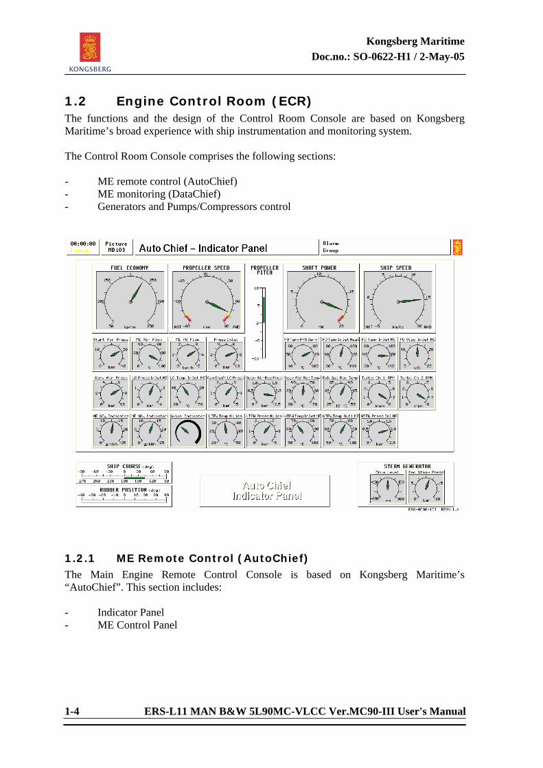
1.2 Engine Control Room (ECR) The functions and the design of the Control Room Console are based on Kongsberg Maritime’s broad experience with ship instrumentation and monitoring system. The Control Room Console comprises the following sections: - ME remote control (AutoChief) - ME monitoring (DataChief) - Generators and Pumps/Compressors control
1.2.1 ME Remote Control (AutoChief) The Main Engine Remote Control Console is based on Kongsberg Maritime’s “AutoChief”. This section includes: - Indicator Panel - ME Control Panel
Kongsberg Maritime Doc.no.: SO-0622-H1 / 2-May-05
ERS-L11 MAN B&W 5L90MC-VLCC Ver.MC90-III User's Manual 1-5
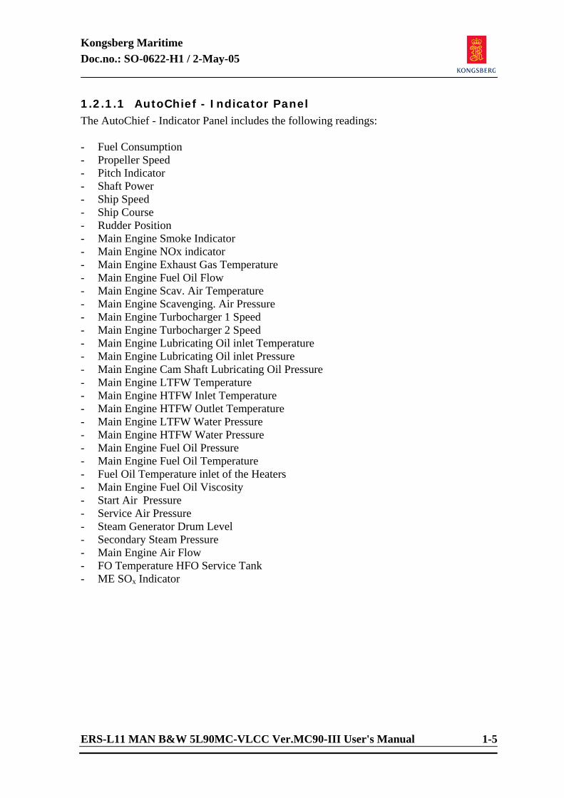
1.2.1.1 AutoChief - Indicator Panel The AutoChief - Indicator Panel includes the following readings: - Fuel Consumption - Propeller Speed - Pitch Indicator - Shaft Power - Ship Speed - Ship Course - Rudder Position - Main Engine Smoke Indicator - Main Engine NOx indicator - Main Engine Exhaust Gas Temperature - Main Engine Fuel Oil Flow - Main Engine Scav. Air Temperature - Main Engine Scavenging. Air Pressure - Main Engine Turbocharger 1 Speed - Main Engine Turbocharger 2 Speed - Main Engine Lubricating Oil inlet Temperature - Main Engine Lubricating Oil inlet Pressure - Main Engine Cam Shaft Lubricating Oil Pressure - Main Engine LTFW Temperature - Main Engine HTFW Inlet Temperature - Main Engine HTFW Outlet Temperature - Main Engine LTFW Water Pressure - Main Engine HTFW Water Pressure - Main Engine Fuel Oil Pressure - Main Engine Fuel Oil Temperature - Fuel Oil Temperature inlet of the Heaters - Main Engine Fuel Oil Viscosity - Start Air Pressure - Service Air Pressure - Steam Generator Drum Level - Secondary Steam Pressure - Main Engine Air Flow - FO Temperature HFO Service Tank - ME SOx Indicator
Kongsberg Maritime Doc.no.: SO-0622-H1 / 2-May-05
1-6 ERS-L11 MAN B&W 5L90MC-VLCC Ver.MC90-III User's Manual
1.2.1.1.1 AutoChief - ME Control Panel The following commands are present at the AutoChief - ME Control Panel: Commands - Throttle RPM/Pitch - Emergency Run/Stop - Responsibility Transfer - Control Mode - Main Engine Start/Stop/Slow turn Status - Fuel Link Command - Control Mode Combi/Fixed Speed/ECO/Fixed Pitch - RPM Setpoint - Emergency Telegraph - Main Engine Slow Down - Main Engine Shut Down - Main Engine Fail Status
Kongsberg Maritime Doc.no.: SO-0622-H1 / 2-May-05
ERS-L11 MAN B&W 5L90MC-VLCC Ver.MC90-III User's Manual 1-7
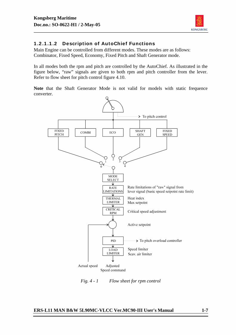
1.2.1.1.2 Description of AutoChief Functions Main Engine can be controlled from different modes. These modes are as follows: Combinator, Fixed Speed, Economy, Fixed Pitch and Shaft Generator mode. In all modes both the rpm and pitch are controlled by the AutoChief. As illustrated in the figure below, “raw” signals are given to both rpm and pitch controller from the lever. Refer to flow sheet for pitch control figure 4.10. Note that the Shaft Generator Mode is not valid for models with static frequence converter.
Fig. 4 - 1 Flow sheet for rpm control
Kongsberg Maritime Doc.no.: SO-0622-H1 / 2-May-05
1-8 ERS-L11 MAN B&W 5L90MC-VLCC Ver.MC90-III User's Manual
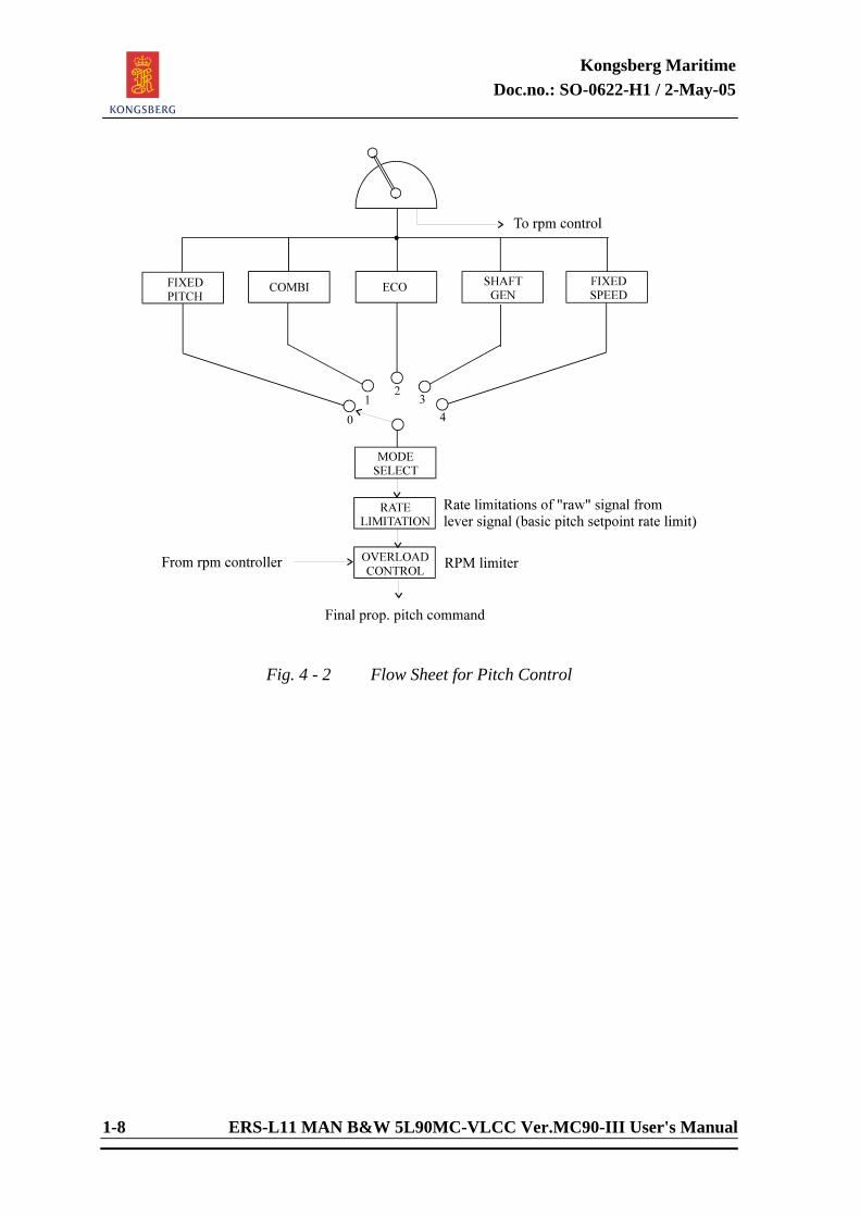
Fig. 4 - 2 Flow Sheet for Pitch Control
Kongsberg Maritime Doc.no.: SO-0622-H1 / 2-May-05
ERS-L11 MAN B&W 5L90MC-VLCC Ver.MC90-III User's Manual 1-9
1.2.1.1.3 Combinator Mode
PITCH %100 100
RPM
100%
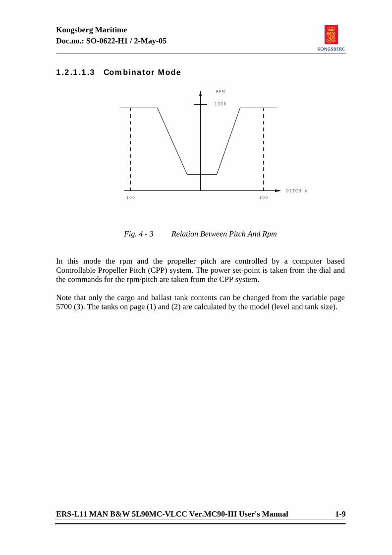
Fig. 4 - 3 Relation Between Pitch And Rpm In this mode the rpm and the propeller pitch are controlled by a computer based Controllable Propeller Pitch (CPP) system. The power set-point is taken from the dial and the commands for the rpm/pitch are taken from the CPP system. Note that only the cargo and ballast tank contents can be changed from the variable page 5700 (3). The tanks on page (1) and (2) are calculated by the model (level and tank size).
Kongsberg Maritime Doc.no.: SO-0622-H1 / 2-May-05
1-10 ERS-L11 MAN B&W 5L90MC-VLCC Ver.MC90-III User's Manual
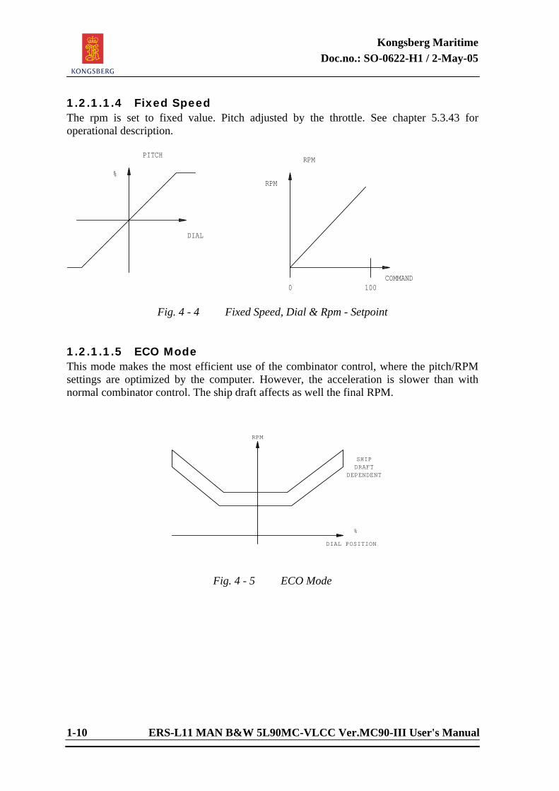
1.2.1.1.4 Fixed Speed The rpm is set to fixed value. Pitch adjusted by the throttle. See chapter 5.3.43 for operational description.
DIAL
%RPM
PITCHRPM
COMMAND0 100
Fig. 4 - 4 Fixed Speed, Dial & Rpm - Setpoint
1.2.1.1.5 ECO Mode This mode makes the most efficient use of the combinator control, where the pitch/RPM settings are optimized by the computer. However, the acceleration is slower than with normal combinator control. The ship draft affects as well the final RPM.
DIAL POSITION
%
RPM
SHIPDRAFT
DEPENDENT
Fig. 4 - 5 ECO Mode
Kongsberg Maritime Doc.no.: SO-0622-H1 / 2-May-05
ERS-L11 MAN B&W 5L90MC-VLCC Ver.MC90-III User's Manual 1-11
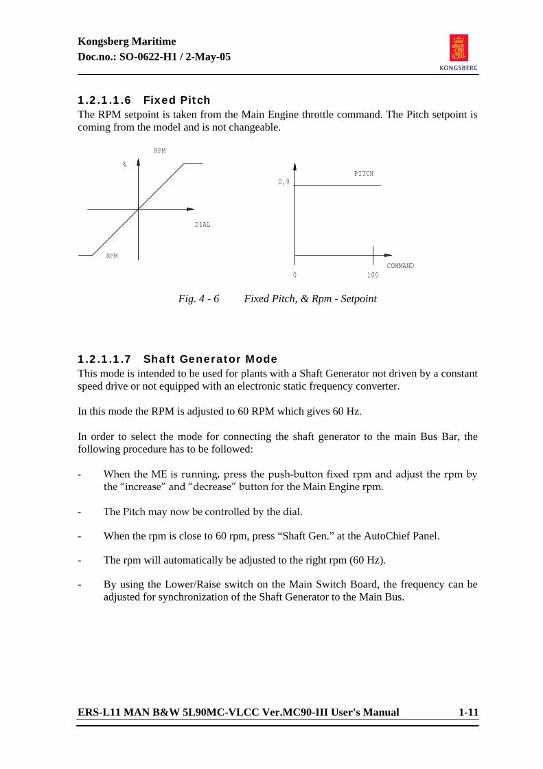
1.2.1.1.6 Fixed Pitch The RPM setpoint is taken from the Main Engine throttle command. The Pitch setpoint is coming from the model and is not changeable.
DIAL
%
RPM
PITCH
RPM
COMMAND0 100
0,9
Fig. 4 - 6 Fixed Pitch, & Rpm - Setpoint
1.2.1.1.7 Shaft Generator Mode This mode is intended to be used for plants with a Shaft Generator not driven by a constant speed drive or not equipped with an electronic static frequency converter. In this mode the RPM is adjusted to 60 RPM which gives 60 Hz. In order to select the mode for connecting the shaft generator to the main Bus Bar, the following procedure has to be followed: - When the ME is running, press the push-button fixed rpm and adjust the rpm by
the “increase” and “decrease” button for the Main Engine rpm. - The Pitch may now be controlled by the dial. - When the rpm is close to 60 rpm, press “Shaft Gen.” at the AutoChief Panel. - The rpm will automatically be adjusted to the right rpm (60 Hz). - By using the Lower/Raise switch on the Main Switch Board, the frequency can be
adjusted for synchronization of the Shaft Generator to the Main Bus.
Kongsberg Maritime Doc.no.: SO-0622-H1 / 2-May-05
1-12 ERS-L11 MAN B&W 5L90MC-VLCC Ver.MC90-III User's Manual
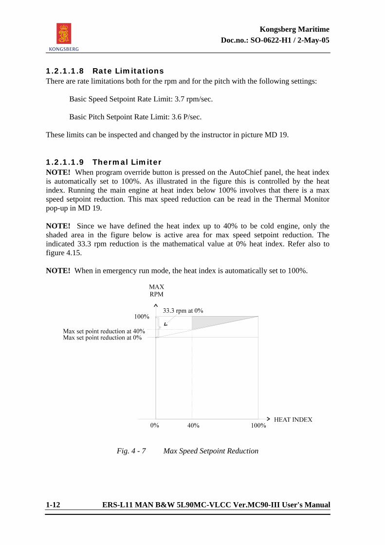
1.2.1.1.8 Rate Limitations There are rate limitations both for the rpm and for the pitch with the following settings: Basic Speed Setpoint Rate Limit: 3.7 rpm/sec. Basic Pitch Setpoint Rate Limit: 3.6 P/sec. These limits can be inspected and changed by the instructor in picture MD 19. 1.2.1.1.9 Thermal Limiter NOTE! When program override button is pressed on the AutoChief panel, the heat index is automatically set to 100%. As illustrated in the figure this is controlled by the heat index. Running the main engine at heat index below 100% involves that there is a max speed setpoint reduction. This max speed reduction can be read in the Thermal Monitor pop-up in MD 19. NOTE! Since we have defined the heat index up to 40% to be cold engine, only the shaded area in the figure below is active area for max speed setpoint reduction. The indicated 33.3 rpm reduction is the mathematical value at 0% heat index. Refer also to figure 4.15. NOTE! When in emergency run mode, the heat index is automatically set to 100%.
Fig. 4 - 7 Max Speed Setpoint Reduction
Kongsberg Maritime Doc.no.: SO-0622-H1 / 2-May-05
ERS-L11 MAN B&W 5L90MC-VLCC Ver.MC90-III User's Manual 1-13
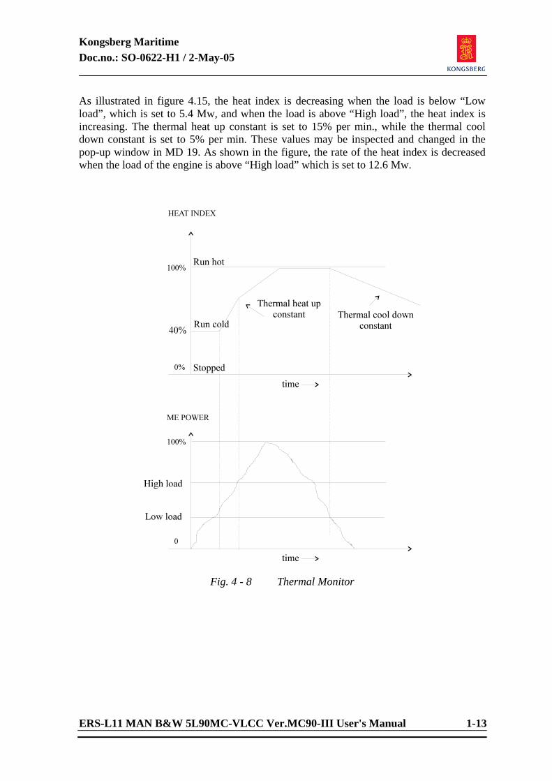
As illustrated in figure 4.15, the heat index is decreasing when the load is below “Low load”, which is set to 5.4 Mw, and when the load is above “High load”, the heat index is increasing. The thermal heat up constant is set to 15% per min., while the thermal cool down constant is set to 5% per min. These values may be inspected and changed in the pop-up window in MD 19. As shown in the figure, the rate of the heat index is decreased when the load of the engine is above “High load” which is set to 12.6 Mw.
Fig. 4 - 8 Thermal Monitor
Kongsberg Maritime Doc.no.: SO-0622-H1 / 2-May-05
1-14 ERS-L11 MAN B&W 5L90MC-VLCC Ver.MC90-III User's Manual
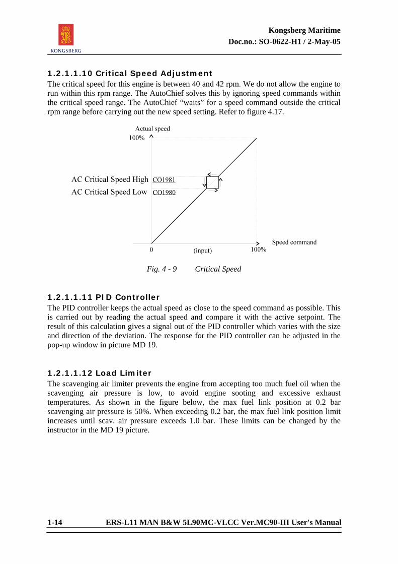
1.2.1.1.10 Critical Speed Adjustment The critical speed for this engine is between 40 and 42 rpm. We do not allow the engine to run within this rpm range. The AutoChief solves this by ignoring speed commands within the critical speed range. The AutoChief “waits” for a speed command outside the critical rpm range before carrying out the new speed setting. Refer to figure 4.17.
Fig. 4 - 9 Critical Speed
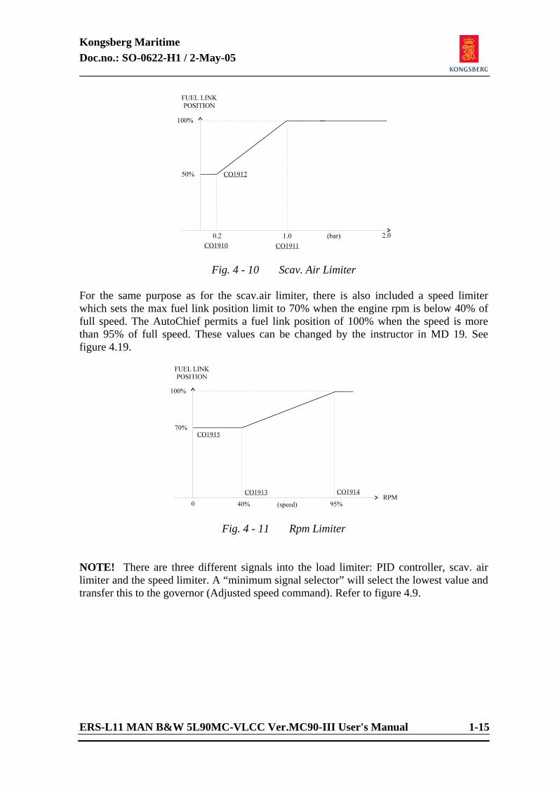
1.2.1.1.11 PID Controller The PID controller keeps the actual speed as close to the speed command as possible. This is carried out by reading the actual speed and compare it with the active setpoint. The result of this calculation gives a signal out of the PID controller which varies with the size and direction of the deviation. The response for the PID controller can be adjusted in the pop-up window in picture MD 19. 1.2.1.1.12 Load Limiter The scavenging air limiter prevents the engine from accepting too much fuel oil when the scavenging air pressure is low, to avoid engine sooting and excessive exhaust temperatures. As shown in the figure below, the max fuel link position at 0.2 bar scavenging air pressure is 50%. When exceeding 0.2 bar, the max fuel link position limit increases until scav. air pressure exceeds 1.0 bar. These limits can be changed by the instructor in the MD 19 picture.
Kongsberg Maritime Doc.no.: SO-0622-H1 / 2-May-05
ERS-L11 MAN B&W 5L90MC-VLCC Ver.MC90-III User's Manual 1-15
Fig. 4 - 10 Scav. Air Limiter For the same purpose as for the scav.air limiter, there is also included a speed limiter which sets the max fuel link position limit to 70% when the engine rpm is below 40% of full speed. The AutoChief permits a fuel link position of 100% when the speed is more than 95% of full speed. These values can be changed by the instructor in MD 19. See figure 4.19.
Fig. 4 - 11 Rpm Limiter
NOTE! There are three different signals into the load limiter: PID controller, scav. air limiter and the speed limiter. A “minimum signal selector” will select the lowest value and transfer this to the governor (Adjusted speed command). Refer to figure 4.9.
Kongsberg Maritime Doc.no.: SO-0622-H1 / 2-May-05
1-16 ERS-L11 MAN B&W 5L90MC-VLCC Ver.MC90-III User's Manual
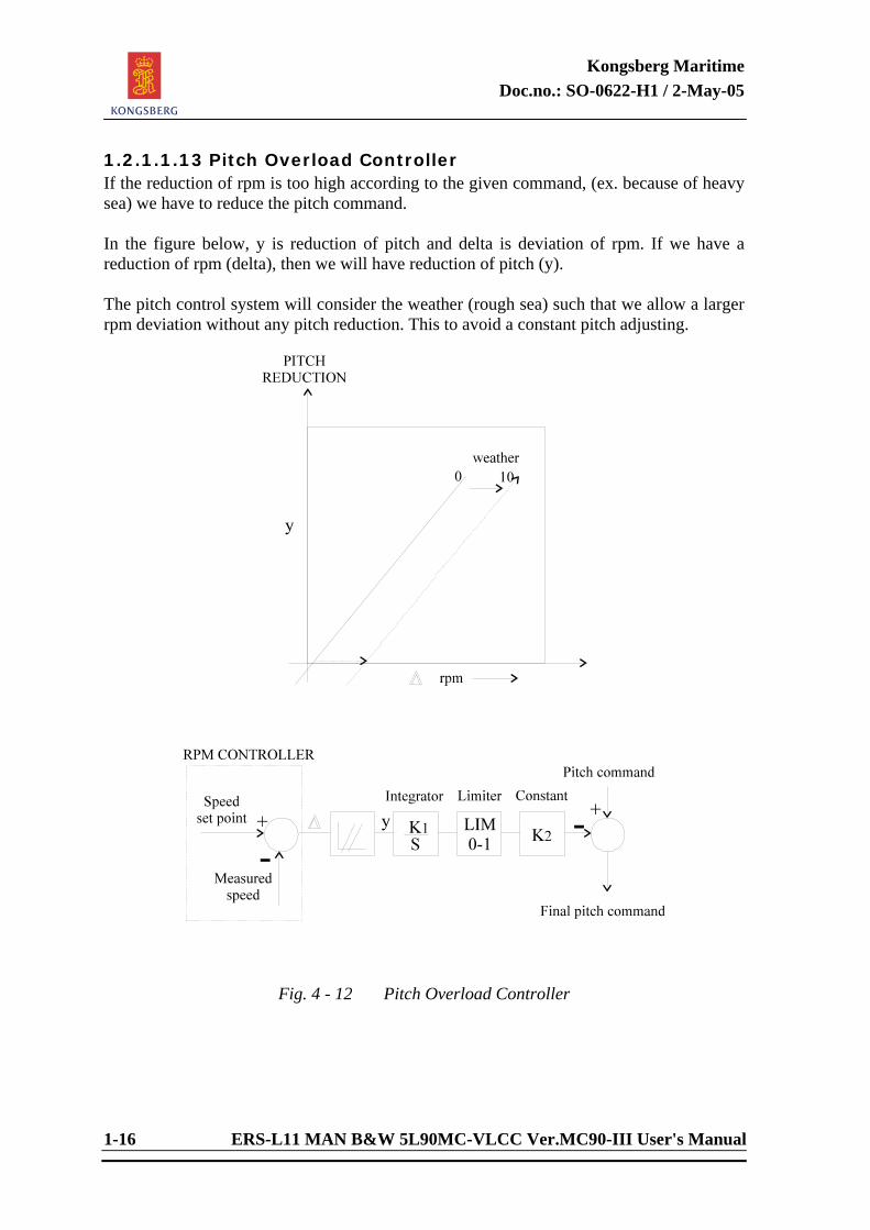
1.2.1.1.13 Pitch Overload Controller If the reduction of rpm is too high according to the given command, (ex. because of heavy sea) we have to reduce the pitch command. In the figure below, y is reduction of pitch and delta is deviation of rpm. If we have a reduction of rpm (delta), then we will have reduction of pitch (y). The pitch control system will consider the weather (rough sea) such that we allow a larger rpm deviation without any pitch reduction. This to avoid a constant pitch adjusting.
Fig. 4 - 12 Pitch Overload Controller
Kongsberg Maritime Doc.no.: SO-0622-H1 / 2-May-05
ERS-L11 MAN B&W 5L90MC-VLCC Ver.MC90-III User's Manual 1-17
1.2.1.1.14 Main Engine Control - Start / Stop: Start and Stop the ME from the Remote Control, when
the combine mode is selected. - Direct Fuel Link: In this mode it is possible to control the fuel link
directly. (only from MD picture) - Locked Fuel Link: This function locks the fuel link to a fixed position to
avoid further movement caused by the RPM governor. This function is useful when setting faults on the main engine (only from MD picture).
- Slowdown: When a slowdown occurs, this button starts flashing. - Shutdown: When a shutdown occurs, this button starts flashing. - Fail: Indicates when other faults from the groups occur. 1.2.1.1.15 Emergency Stop When this switch is activated, the engine is stopped since the fuel pumps are forced into “Stop” position. 1.2.1.1.16 Emergency Run - Shut Down Override: All shut downs except for tor Overspeed are cancelled. - Slow Down Override: All slow downs are cancelled. - Program Override: Load program is cancelled, heat index is automatically set to 100%. - Limits Override: Scavenge air and rpm limiters are overridden. Start setpoint is increased. Start fail is cancelled. The rpm level for Brake Air ON is increased. 1.2.1.1.17 Fuel Link Command These two instruments show the actual fuel link command and the limited fuel command which setpoint is used by the governor controller.
Kongsberg Maritime Doc.no.: SO-0622-H1 / 2-May-05
1-18 ERS-L11 MAN B&W 5L90MC-VLCC Ver.MC90-III User's Manual
1.2.1.1.18 Responsibility Transfer - Bridge Transfer of the responsibility from the Engine
Room to Bridge. (md 110) - Eng. Control Room Engine Control Room responsibility. Control of
the actual command is from the engine room control console.
- Local Control Control of the main engine is done from the local
control console in the engine room, responsibility is transferred to and from the local console by using the push-button on the local control console.
1.2.1.1.19 Transfer of Responsibility from ECR to Bridge To transfer the control from ECR to bridge, press the push-button “BRIDGE” on AutoChief panel. The button then starts to flash. Answer by pressing the button “BRIDGE” on the AutoChief Bridge Control panel. The button “BRIDGE” turns to steady light. or: Open variable Page 9010 and set the tag X07540 to “ 1 “. The push-button “BRIDGE” turns to steady light. The ship is now controlled from the bridge and may be run on the emergency telegraph or by the control handle or from the variable pages. To transfer back to ECR, just press ECR on the AutoChief panel. NOTE! To change the operation of Emergency Telegraph between Engine room and
Engine Control room to operate between Engine Control room and Bridge, the Bridge Telegraph has to be enabled on the variable Page 9010.
1.2.1.1.20 Safety System To operate the main engine safely, all critical parameters must be monitored in order to activate alarm and, if required, initiate automatic slowdown- or shutdown procedures. Parameters to be included in these procedures, and their setting of limitations, are decided by the engine maker in co-operation with classification and national navigation authorities. The Slowdown - Shutdown are monitored by the DataChief and transferred to AutoChief for initiation of slowdown/shutdown. Each of the slowdown and shutdown parameters is grouped and represented by an indicator light on the AutoChief panel.
Kongsberg Maritime Doc.no.: SO-0622-H1 / 2-May-05
ERS-L11 MAN B&W 5L90MC-VLCC Ver.MC90-III User's Manual 1-19
When the indicator light starts flashing, slowdown/shutdown procedures are initiated. - The safety system gives the operator the possibility to override Shutdowns and
Slowdowns by pressing the Override SHD/SLD buttons.
The system will (depending on set-up) give the operator a warning on slow down and shut down. The default time delay for slow down to be activated is 120 seconds. Within this period the operator may cancel the slow down. The actual diode will flash as long as the cause for slow down is present.
The default time delay for shut down to be activated is 30 seconds. Within this
period the operator may cancel the shut down (except for the overspeed). The actual diode will flash as long as the cause for shut down is present.
The slow down/shut down logic with delays are available from the Safety Override
pop-up window in MD13 (ME Control System) and from the variable page 1914-1915. The settings can be adjusted by the customer. See slow down and shut down logic selection below.
- 0 = overrideable, with delay - 1 = delayed signal, not overrideable - 2 = instant signal (no delay), overrideable - 3 = instant signal and not overrideable 1.2.1.1.21 Main Engine Shutdown Shutdown of Main Engines occurs if: - Main LO Inlet Pressure < 1,0 bar - Cam Shaft LO Pressure < 1,5 bar - Thrust Bearings Temperature > 85 °C - Cylinder cooling water temperature > 96 °C - Main Engine overspeed > 80 rpm
Kongsberg Maritime Doc.no.: SO-0622-H1 / 2-May-05
1-20 ERS-L11 MAN B&W 5L90MC-VLCC Ver.MC90-III User's Manual
1.2.1.1.22 Main Engine Slowdown Slowdown of Main Engine occurs if: - Main LO Inlet Pressure < 1,2 bar - Cam Shaft LO Pressure > 2.0 bar - Thrust Bearing Temperature > 75 °C - Piston Cooling Oil Flow < 17 t/h - Scav. Air Cyl. Inlet Temperature > 75 °C - Main LO Inlet Temperature > 60 °C - Cam Shaft LO Temperature > 70 °C - Piston LO Outlet Temperature > 70 °C - Main Bearing Temperature > 80 °C - Cyl. Exhaust Temperature > 460 °C 1.2.1.1.23 Main Engine Start Inhibited Start from AutoChief is inhibit if: - Main Engine in Local Control - Start failure - Reversing failure - Breaking failure - Turning Gear in - Start Air press < 12 bar - Control Air press < 2 bar
Kongsberg Maritime Doc.no.: SO-0622-H1 / 2-May-05
ERS-L11 MAN B&W 5L90MC-VLCC Ver.MC90-III User's Manual 1-21
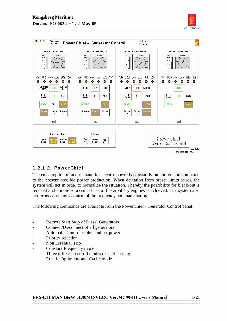
1.2.1.2 PowerChief The consumption of and demand for electric power is constantly monitored and compared to the present possible power production. When deviation from preset limits arises, the system will act in order to normalize the situation. Thereby the possibility for black-out is reduced and a more economical use of the auxiliary engines is achieved. The system also performs continuous control of the frequency and load-sharing. The following commands are available from the PowerChief - Generator Control panel: - Remote Start/Stop of Diesel Generators - Connect/Disconnect of all generators - Automatic Control of demand for power - Priority selection - Non Essential Trip - Constant Frequency mode - Three different control modes of load-sharing: Equal-, Optimum- and Cyclic mode
Kongsberg Maritime Doc.no.: SO-0622-H1 / 2-May-05
1-22 ERS-L11 MAN B&W 5L90MC-VLCC Ver.MC90-III User's Manual
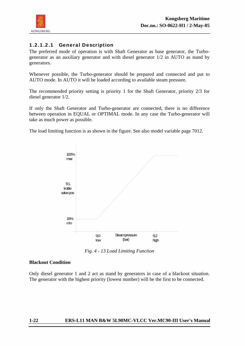
1.2.1.2.1 General Description The preferred mode of operation is with Shaft Generator as base generator, the Turbo-generator as an auxiliary generator and with diesel generator 1/2 in AUTO as stand by generators. Whenever possible, the Turbo-generator should be prepared and connected and put to AUTO mode. In AUTO it will be loaded according to available steam pressure. The recommended priority setting is priority 1 for the Shaft Generator, priority 2/3 for diesel generator 1/2. If only the Shaft Generator and Turbo-generator are connected, there is no difference between operation in EQUAL or OPTIMAL mode. In any case the Turbo-generator will take as much power as possible. The load limiting function is as shown in the figure. See also model variable page 7012.
15%min
Steampressure(bar)
TGtrottle
valvepos
100%max
9,2high
9,0low
Fig. 4 - 13 Load Limiting Function
Blackout Condition Only diesel generator 1 and 2 act as stand by generators in case of a blackout situation. The generator with the highest priority (lowest number) will be the first to be connected.
Kongsberg Maritime Doc.no.: SO-0622-H1 / 2-May-05
ERS-L11 MAN B&W 5L90MC-VLCC Ver.MC90-III User's Manual 1-23
Operating on Shaft Generator and Turbo-generator only. Special Considerations If the speed command from the AUTO Chief speed control level is lower than required for producing the present electric power, the speed command is delayed 20 seconds while a standby diesel generator is started and connected. The PowerChief control mode will be set to Equal mode, for maximum safety. The new diesel generator will be kept connected, as the normal stop logic of the PowerChief is overridden. Below 35 rpm the Shaft Generator will be taken out of AUTO. If the ME is stopped or reversed, the Shaft Generator clutch will disconnect. At low ME power the oil fired boiler will normally start and keep the steam pressure above 8 bar. The Turbo-generator throttle valve is limited to a value sufficient for keeping it connected at minimum steam pressure and close to zero power. The Turbo-generator is not disconnected unless “driver” alarms arise. Figure 4-25 indicates the mechanism for auto start of diesel generator at manoeuvring. “Special action” is released while crossing boarder from high to low area.
Kongsberg Maritime Doc.no.: SO-0622-H1 / 2-May-05
1-24 ERS-L11 MAN B&W 5L90MC-VLCC Ver.MC90-III User's Manual
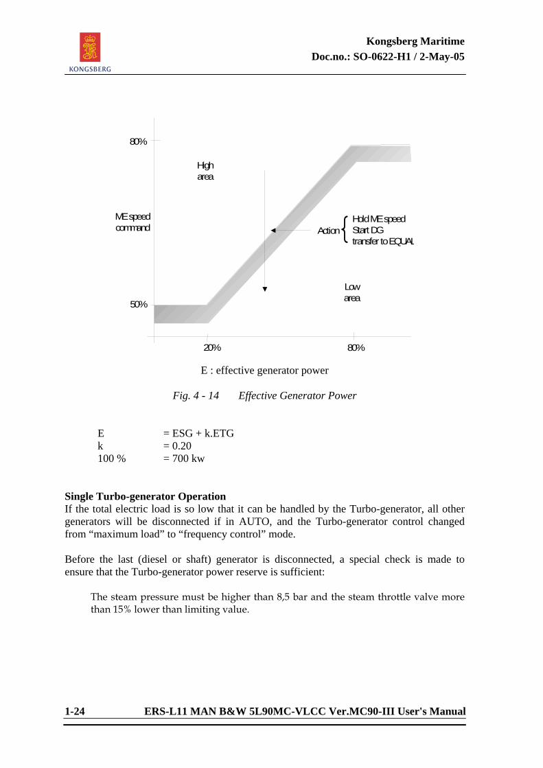
50%
Higharea
Lowarea
Action{HoldMEspeedStartDGtransfer toEQUAL
MEspeedcommand
80%
80%20%
E : effective generator power
Fig. 4 - 14 Effective Generator Power E = ESG + k.ETG k = 0.20 100 % = 700 kw Single Turbo-generator Operation If the total electric load is so low that it can be handled by the Turbo-generator, all other generators will be disconnected if in AUTO, and the Turbo-generator control changed from “maximum load” to “frequency control” mode. Before the last (diesel or shaft) generator is disconnected, a special check is made to ensure that the Turbo-generator power reserve is sufficient: The steam pressure must be higher than 8,5 bar and the steam throttle valve more
than 15% lower than limiting value.
Kongsberg Maritime Doc.no.: SO-0622-H1 / 2-May-05
ERS-L11 MAN B&W 5L90MC-VLCC Ver.MC90-III User's Manual 1-25
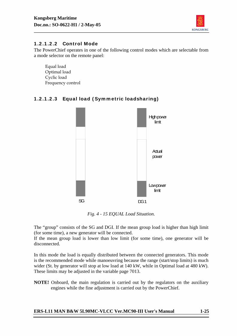
1.2.1.2.2 Control Mode The PowerChief operates in one of the following control modes which are selectable from a mode selector on the remote panel: Equal load Optimal load Cyclic load Frequency control 1.2.1.2.3 Equal load (Symmetric loadsharing)
Highpowerlimit
Actualpower
Lowpowerlimit
SG DG1
Fig. 4 - 15 EQUAL Load Situation.
The “group” consists of the SG and DGI. If the mean group load is higher than high limit (for some time), a new generator will be connected. If the mean group load is lower than low limit (for some time), one generator will be disconnected. In this mode the load is equally distributed between the connected generators. This mode is the recommended mode while manoeuvring because the range (start/stop limits) is much wider (St. by generator will stop at low load at 140 kW, while in Optimal load at 480 kW). These limits may be adjusted in the variable page 7013. NOTE! Onboard, the main regulation is carried out by the regulators on the auxiliary
engines while the fine adjustment is carried out by the PowerChief.
Kongsberg Maritime Doc.no.: SO-0622-H1 / 2-May-05
1-26 ERS-L11 MAN B&W 5L90MC-VLCC Ver.MC90-III User's Manual
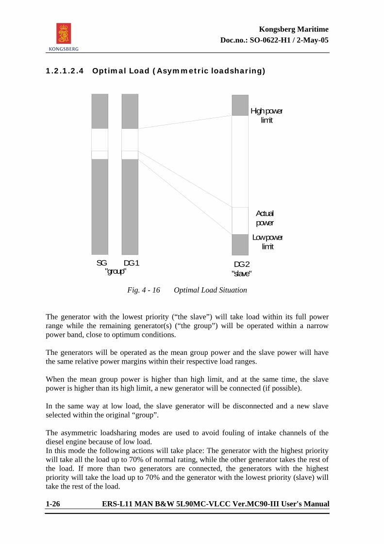
1.2.1.2.4 Optimal Load (Asymmetric loadsharing)
Highpowerlimit
Actualpower
Lowpowerlimit
DG2"slave""group"
DG1SG
Fig. 4 - 16 Optimal Load Situation
The generator with the lowest priority (“the slave”) will take load within its full power range while the remaining generator(s) (“the group”) will be operated within a narrow power band, close to optimum conditions. The generators will be operated as the mean group power and the slave power will have the same relative power margins within their respective load ranges. When the mean group power is higher than high limit, and at the same time, the slave power is higher than its high limit, a new generator will be connected (if possible). In the same way at low load, the slave generator will be disconnected and a new slave selected within the original “group”. The asymmetric loadsharing modes are used to avoid fouling of intake channels of the diesel engine because of low load. In this mode the following actions will take place: The generator with the highest priority will take all the load up to 70% of normal rating, while the other generator takes the rest of the load. If more than two generators are connected, the generators with the highest priority will take the load up to 70% and the generator with the lowest priority (slave) will take the rest of the load.
Kongsberg Maritime Doc.no.: SO-0622-H1 / 2-May-05
ERS-L11 MAN B&W 5L90MC-VLCC Ver.MC90-III User's Manual 1-27
NOTE! The Turbo and Shaft generator can never become a slave generator. This is taken care of by the PowerChief. However, as one of the high priority generators, the shaft generator will act as one of the high priority diesel generators (take load up to 70%). The Turbo-generator has its own logic which means that the Turbo-generator does not take any notice of the different load limits in the different loadsharing modes. This because of the fact that the most economical way to run the Turbo-generator is running at full load all the time.
The load limits (the PowerChief keeps the load for these generators within these limits) for the highest priority generators are 480 to 600 kW. The load limits for the slave generator are 50 to 600 kW. When load dependent stop (because of low load) of generator, the slave generator will stop and the generator with the lowest priority of the remaining generators will become the new slave. If only one generator is running (because of the load situation), the load limits in Optimal load mode will automatically change to the High single load limit which is set to 680kW. This means that the generator has to be loaded with 680 kW before a stand by generator start request will be carried out. See variable page 7013. As we can see, we allow a single running generator to take more load in this mode. This mode is not recommended while manoeuvring. 1.2.1.2.5 Cyclic Load (Asymmetric loadsharing) This mode is identical with “optimal load” except for the mechanism for slave function selection. The slave function is no longer fixed by priority but will pass from generator to generator (“cyclic”) according to a timer. The slave period can be adjusted on model variable page 7012. The function is intended used to avoid that the same generator is being operated at low unfavourable load conditions for too long periods, risking sooting and burning of inlet air valves due to low scavenging pressure. As for Optimal load this mode is not recommended while manoeuvring because of the narrow load range (480-600). 1.2.1.2.6 Frequency Control Normally, when in Auto Mode, the frequency adjustment is carried out by the master generator while the stand by generator takes care of the loadsharing. In the ERS simulator this function is separated for that purpose to show the student the connection between the frequency (rpm) and the load (speed-droop). When this mode is used, the PowerChief controls the frequency and adjusts it continuously to maintain 60 Hz.
Kongsberg Maritime Doc.no.: SO-0622-H1 / 2-May-05
1-28 ERS-L11 MAN B&W 5L90MC-VLCC Ver.MC90-III User's Manual
1.2.1.2.7 Operating Mode Run: This lamp is lit when the generator is running. Start: This is a manual start initiated from the PowerChief panel. Note
that it is only possible to start the generator when the “READY” lamp is on, and that the AUTO-function is switched off.
Stop: This is a manual stop initiated from the PowerChief panel. Note
that the generator has to be disconnected from the bus before it is possible to stop the diesel generator.
In: This lamp is lit when the generator is connected to the bus bar. Connect: To connect a running diesel generator to the bus bar, press this
push-button. The PowerChief will then automatically synchronize and connect it to the bus bar. Load sharing takes place according to the mode selected.
Disconnect: To disconnect the generator from the bus bar, switch off the
AUTO function followed by pressing the DISCONNECT. The PowerChief will automatically reduce the load of the generator to minimum, followed by disconnection.
Ready: This lamp is on when the following conditions are present: - DG in Remote Control at the local panel. - Priming Pump running.
- No alarms in the Diesel-generator system For the Shaft Generator to be ready for remote operation there
must be power on the main bus bar 2 (bus tie breaker must be connected!) The clutch air supply valve must be open and the clutch control in “remote”. The ME must be running faster than 34 rpm.
Kongsberg Maritime Doc.no.: SO-0622-H1 / 2-May-05
ERS-L11 MAN B&W 5L90MC-VLCC Ver.MC90-III User's Manual 1-29
Auto: To select automatic operation of the diesel generators, press this push-button. Then the PowerChief will take care of Start/Stop, Connect/Disconnect and load sharing of the generator. If this lamp is flashing, the Auto mode is cancelled because of local disturbance i.e. manually start/stop of pumps or open/close of valves belonging to the diesel generator system. If the generator driver exceeds its capacity, a new generator will be started and connected if possible. For the diesel generators the maximum fuel link position can be set less than 100 % if desired, see governor display, MD71/72, load limit setting, or model variable page 7110/7210. The Shaft generator’s static converter generates a load limit signal at high loads (relative to generator speed). This signal is used by PowerChief for starting up another generator when required. If a “driver alarm” arises while a generator is in AUTO and connected, a new generator will be started and connected before the generator with problems is disconnected. If no stand by generator is available, the alarmed generator will be taken out of AUTO control (indicated by flashing AUTO) but kept connected. Diesel generators that are in AUTO mode and not connected within a given period, will be stopped. The maximum idling period can be adjusted, see model variable page 7012. The Turbo-generator can only be started or stopped locally. The following alarms are diesel generator “driver alarms”: T03020 : Fw temp outlet DG high P03012 : Fw pressure inlet DG low T03057 : Exhaust temp onlet TBCH high T03060 : Exhaust temp outlet TBCH high T03051 : Air temp outlet AIRC high P03066 : FO filter dp high P03032 : LO press inlet DG low T03037 : LO temp inlet DG high T03034 : bearing 1 temp high T03035 : bearing 2 temp high
Kongsberg Maritime Doc.no.: SO-0622-H1 / 2-May-05
1-30 ERS-L11 MAN B&W 5L90MC-VLCC Ver.MC90-III User's Manual
Turbo-generator “driver alarms” are as follows: P04601 : steam pressure inlet TG low T04600 : steam temp inlet TG low P04640 : LO press inlet bearings low T04632 : LO tank temp high P04617 : sealing steam pressure low L04703 : condenser hotwell level high P04700 : condenser pressure high SG “driver alarms” are: N06974 : ME rpm low ME slow down ME shut down
Priority 1: This generator has the highest priority, i.e. first in and last out. Priority 2: This generator has the second priority, i.e. will connect later than
no. 1 and disconnect earlier than number 1. Priority 3: This generator has the third priority, i.e. will connect later than
no. 2 and disconnect earlier than no. 2. Non Essen. Trip: This lamp is on when the non-essential load is tripped due to
high load. - Main Air Condition - Main Ventilation 1 & 2 - Ventilation 1& 2 - Main Refrig. System High Power: This lamp is on when the power rating is higher than normal
rating for the generator. Gen. S/S Request: This lamp is on when the load of generators connected to the
main bus bar is too high, and the PowerChief requests start of the stand-by generator. All consumers connected to the PowerChief + Bow Thruster will give start request to st. by generator when need of power. However, there is not included a “start inhibit” of heavy consumer in the system.
Kongsberg Maritime Doc.no.: SO-0622-H1 / 2-May-05
ERS-L11 MAN B&W 5L90MC-VLCC Ver.MC90-III User's Manual 1-31
1.2.1.2.8 Safety System for the Auxiliary Engines The safety system for the auxiliary engines is located in the engine room at the DG local panels. It operates as a back-up system for the PowerChief and protects the auxiliary engines if the latter fails; if the process is disconnected or if the engines run in manual mode. The back-up safety system is monitoring the same parameters by binary sensors as the computer system is monitoring using analogue sensors, and in it also monitors the overspeed safety system. When this system is activated, the TRIP lamp flashes and cannot be reset until a normal situation is established. 1.2.1.2.9 Alarms and Messages from PowerChief Alarms An alarm is announced by an acoustic buzzer signal, a flashing light in the group alarm lamp at the alarm console and logging of the alarm at the printer. PowerChief generates alarms when automatic actions fail, i.e. the result of the action is not obtained within the normal period of time. Messages A message is announced by logging of the message. PowerChief generates important messages when manual actions, initiated from the Data Safe panel fail, and when manual and automatic actions are successfully executed.
Kongsberg Maritime Doc.no.: SO-0622-H1 / 2-May-05
1-32 ERS-L11 MAN B&W 5L90MC-VLCC Ver.MC90-III User's Manual
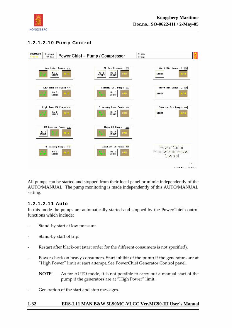
1.2.1.2.10 Pump Control
All pumps can be started and stopped from their local panel or mimic independently of the AUTO/MANUAL. The pump monitoring is made independently of this AUTO/MANUAL setting. 1.2.1.2.11 Auto In this mode the pumps are automatically started and stopped by the PowerChief control functions which include: - Stand-by start at low pressure. - Stand-by start of trip. - Restart after black-out (start order for the different consumers is not specified). - Power check on heavy consumers. Start inhibit of the pump if the generators are at
“High Power” limit at start attempt. See PowerChief Generator Control panel.
NOTE! As for AUTO mode, it is not possible to carry out a manual start of the pump if the generators are at “High Power” limit.
- Generation of the start and stop messages.
Kongsberg Maritime Doc.no.: SO-0622-H1 / 2-May-05
ERS-L11 MAN B&W 5L90MC-VLCC Ver.MC90-III User's Manual 1-33
If there has been a disturbance in the AUTO system, for instance, a local start/stop or an alarm has occurred, the auto lamp and the start lamp start flashing, which means that the auto function has been turned off. 1.2.1.2.12 Manual In this mode (Auto lamp is off) starting and stopping of the pumps have to be done manually from the control panel. 1.2.1.2.13 Stand-by of Low Pressure When pressure drops below the “stand-by start limits”, the stand-by unit is started automatically. The stand-by limits may be changed by the instructor. Most of the low pressure alarms are subject to “Automatic alarm blocking”. The stand-by start function will as well be blocked during the same period of time. 1.2.1.2.14 Automatic Restart after Black-out After recovery from black-out, the PowerChief will restart all units which were running at the time black-out occurred. Start conditions like AUTO-mode, no active alarms etc., also apply for this start. The restart procedure follows a present time sequence. 1.2.1.2.15 Compressor Control The compressor control is based on the same principles as for the pump control system. Auto Mode: In this mode the compressors are automatically
started and stopped by the PowerChief. Automatic start takes place when the pressure drops below a certain limit.
The compressors are also connected to the power
check system, so that a compressor start may be delayed if the generators are at “High Power” limit at start attempt. NOTE! As for AUTO mode, it is not possible to carry out a manual start of the compressor if the generators are at “High Power” limit. The start air compressors will automatically alter to be the Master/Slave compressor. If the Master compressor is not able to increase the pressure within a certain period of time (approx. 2-2.5 minutes) the slave compressor will also start.
Kongsberg Maritime Doc.no.: SO-0622-H1 / 2-May-05
1-34 ERS-L11 MAN B&W 5L90MC-VLCC Ver.MC90-III User's Manual
The start/stop limits for the compressors can be changed from the PowerChief variable pages.
A flashing AUTO or START lamp indicates there
has been a disturbance in the system. To reset the fault, press the start push-button to check whether the compressor is running or not, then press the auto push-button to get back to auto mode.
Manual Mode: In this mode (AUTO lamp extinguished) starting
and stopping of the pumps have to be done manually from the control panel.
NOTE! The above start inhibitations will
normally not occur when running the generators in AUTO mode since the PowerChief will start a stand-by generator before the connected generators reach the “High Power” limit.
1.2.1.2.16 PowerChief Pump - Compressor Control The Pump - Compressor Control panel includes automatic control of: - Sea Water Pumps 1 and 2 - Low Temp Fresh Water Pumps 1 and 2 - High Temp Fresh Water Pumps 1 and 2 - Main Engine Auxiliary Blowers 1 and 2 - Main Lubrication Pumps 1 and 2 - Camshaft Lubrication Pumps 1 and 2 - FO Booster Pumps 1 and 2 - FO Supply Pumps 1 and 2 - Steering Gear Pump 1 and 2 - Start Air Compressor 1 - Start Air Compressor 2 - Service Air Compressor - Propeller Servo Pump 1 and 2 (only visible when CPP is active) - Thermal Oil Pumps 1.2.1.2.17 Manual Start and Stop Each of the above individual components can be started and stopped from the PowerChief Pump - Compressor Control panel. There will be a start inhibit if the power rating of generators is higher than normal rating (“High Power” is indicated on the PowerChief Generator Control panel).
Kongsberg Maritime Doc.no.: SO-0622-H1 / 2-May-05
ERS-L11 MAN B&W 5L90MC-VLCC Ver.MC90-III User's Manual 1-35
1.2.1.2.18 Automatic Start and Stop In this mode the pumps and compressors are automatically started and stopped by the control functions including: - Stand-By Start at Low Pressure - Auto Stop at High Pressure - Restart after Black-Out - Power Check (start inhibit at “High Power”) on generators - Cyclic operation of units The pumps and compressors with st.by logic included are as follows: - Main SW Pump /start - Thermal Oil Pump /start - ME Aux. Blower /start/stop Cam Shaft LO Pump /start - Main LTFW Pump /start - Prop Servo LO Pump /start - Main HTFW Pump /start - Steering Gear Pump /start - FO Booster pump /start - Start Air Compr. /start/stop - FO Supply pump /start - Service Air Compr. /start/stop - Main LO Pump /start 1.2.1.2.19 Automatic Restart, Boiler System Pumps The following pumps, not found on the PowerChief Pump/Compressor console, will also automatically restart after blackout: - Exhaust boiler water circ. pump 1/2 - Boiler combustion air fan - Boiler HFO pump - Boiler DO pump - Main condensate pump - Condenser vacuum pump 1/2 - Main feed water pump
Kongsberg Maritime Doc.no.: SO-0622-H1 / 2-May-05
1-36 ERS-L11 MAN B&W 5L90MC-VLCC Ver.MC90-III User's Manual
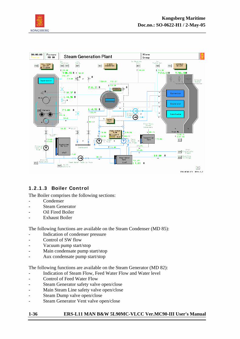
1.2.1.3 Boiler Control The Boiler comprises the following sections: - Condenser - Steam Generator - Oil Fired Boiler - Exhaust Boiler The following functions are available on the Steam Condenser (MD 85): - Indication of condenser pressure - Control of SW flow - Vacuum pump start/stop - Main condensate pump start/stop - Aux condensate pump start/stop The following functions are available on the Steam Generator (MD 82): - Indication of Steam Flow, Feed Water Flow and Water level - Control of Feed Water Flow - Steam Generator safety valve open/close - Main Steam Line safety valve open/close - Steam Dump valve open/close - Steam Generator Vent valve open/close
Kongsberg Maritime Doc.no.: SO-0622-H1 / 2-May-05
ERS-L11 MAN B&W 5L90MC-VLCC Ver.MC90-III User's Manual 1-37
- Main Steam Shut Off valve open/close - Main Feed Water Pump start/stop - Aux Feed Water Pump start/stop - Steam Generator Drain valve open/close - Main Steam Line Drain The following functions are available on the Boiler Combustion (MD 84): - Indication of Fuel Oil Flow, Combustion Air Flow, Primary Steam Pressure, Secondary Steam Pressure, Steam Temperature, Oxygen Content, Water Level, Boiler Trip and Smoke Density - Combustion Air Fan start/stop - Selection of Burner type - Change over valve DO/HFO - DO pump start/stop - HFO pump start/stop - HFO Heater Steam valve open/close - Atomizing Steam valve open/close - Control of Oil Flow - Control of Air Flow - Master Controller - Excess Air Controller - Burner no 1 on/off - Burner no 2 on/off - Burner Management selector Ready/Auto - Purging operation and indication - Primary Drum Safety valve open/close - Primary Drum Vent valve open/close - Superheater vent/drain valve open/close - Primary FW shut off valve open/close - Primary FW Make Up pump start/stop - Primary Drum Drain valve open/close - Primary Drum Vent valve open/close - Primary Water Heater on/off - Soot Blowing Steam on/off The following functions are available on the Exhaust Boiler (mD 81): - Indication of Exhaust inlet temp, Exhaust outlet temp, Economizer FW outlet temp
and Superheater Steam outlet temp. - Control of Exhaust Damper including Auto/Man selection - Water Circulation Pump start/stop - Superheater Drain/Vent valve open/close - Soot Blowing Air on/off
Kongsberg Maritime Doc.no.: SO-0622-H1 / 2-May-05
1-38 ERS-L11 MAN B&W 5L90MC-VLCC Ver.MC90-III User's Manual
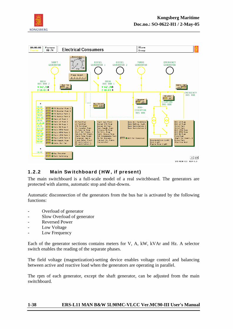
1.2.2 Main Switchboard (HW, if present) The main switchboard is a full-scale model of a real switchboard. The generators are protected with alarms, automatic stop and shut-downs. Automatic disconnection of the generators from the bus bar is activated by the following functions: - Overload of generator - Slow Overload of generator - Reversed Power - Low Voltage - Low Frequency Each of the generator sections contains meters for V, A, kW, kVAr and Hz. A selector switch enables the reading of the separate phases. The field voltage (magnetization)-setting device enables voltage control and balancing between active and reactive load when the generators are operating in parallel. The rpm of each generator, except the shaft generator, can be adjusted from the main switchboard.
Kongsberg Maritime Doc.no.: SO-0622-H1 / 2-May-05
ERS-L11 MAN B&W 5L90MC-VLCC Ver.MC90-III User's Manual 1-39
The main switchboard comprises all controls and indicators usually available on real switchboards and includes the following sections: - Shaft Generator w/ Bus Bar 2 - Diesel Generator 1 & 2 - Turbo Generator - Synchronization w/ Shore power - Emergency Generator w/ Main Bus Bar and Emergency Bus Bar - Miscellaneous 1.2.2.1 Bus Bars The power distribution is divided into two bus bars. Consumers connected are: Emergency Bus Bar: - Diesel Generators LO priming pumps Turbo Generator LO priming pump - Shaft Generators LO priming pumps - Aux. FW pump - Aux. SW pump - Start Air Compressor no. 2 - Fire pump - Bilge pump - Steering gear 1 & 2 Main Bus Bar 2: - Bow Thruster - Deck Machinery Main Bus Bar 1: - All remaining consumers The main bus bar is normally connected to the emergency bus bar. Isolation of the emergency bus bar is only done when the emergency generator is running.
Kongsberg Maritime Doc.no.: SO-0622-H1 / 2-May-05
1-40 ERS-L11 MAN B&W 5L90MC-VLCC Ver.MC90-III User's Manual
1.2.2.2 Emergency Generator The emergency generator section contains indicators for Voltage and Power consumption. The emergency generator can be controlled automatically. When in AUTO, the emergency generator starts and connects automatically after a blackout. As soon as one of the main generators is connected, the emergency generator will be disconnected and stopped after an idling period. 1.2.2.2.1 Emergency Panel Description - START Indication that Emergency Generator is running. - IN Indication lamp for the circuit breaker status. The power distribution is divided into two bus bars; Main Bus Bar and the Emergency Bus Bar. For the Main Bus Bar the main circuit breakers of vital pumps are available at lower part of the panel section and for the Emergency Bus Bar, which indicates the connected consumer. Main Bus Bar 1 Circuit Breakers: - SW Pump No. 1 & 2 - LTFW Pump No. 1 & 2 - HTFW Pump No. 1 & 2 - Main LO Pump No. 1 & 2 - FO Supply Pump No. 1 & 2 - FO Booster Pump No. 1 & 2 - Boiler Combustion Air Fan - Auxiliary Feed water pump Emergency Bus Bar consumers: - Diesel Generators LO priming pumps - Shaft Generators LO priming pumps - Aux. FW pump - Aux. SW pump - Start Air Compressor no. 2 - Fire Pump - Bilge pump - Steering gear 1 & 2 The main bus bar is normally connected to the Emergency Bus Bar. Isolation of the Emergency Bus Bar is only done when running the emergency generator.
Kongsberg Maritime Doc.no.: SO-0622-H1 / 2-May-05
ERS-L11 MAN B&W 5L90MC-VLCC Ver.MC90-III User's Manual 1-41
1.2.2.3 Diesel Generator 1 & 2 The el-power supply system comprises two identical diesel generators, modelled as high/medium speed engines with all vital subsystems such as rpm governor, cooling water, lubrication oil, start air, turbo-charger, air cooler and fuel oil. Voltage and frequency readings of the Generator bus bar are available on the panel. Together with speed adjustment, the operator is allowed to connect the generator with verification of synchronizing to the main bus bar. The Diesel Generator section contains a volt/ampere/watt/frequency/volt ampere reactive meter. A selector switch enables reading of difference phase to the generator.
Kongsberg Maritime Doc.no.: SO-0622-H1 / 2-May-05
1-42 ERS-L11 MAN B&W 5L90MC-VLCC Ver.MC90-III User's Manual
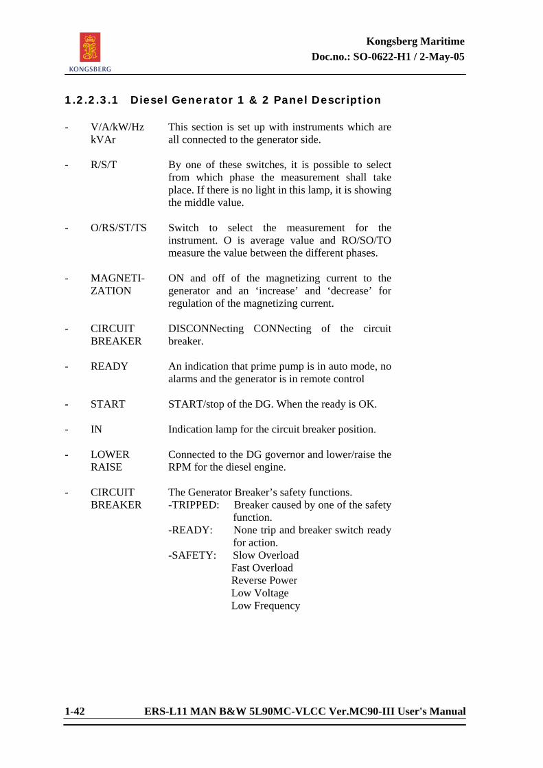
1.2.2.3.1 Diesel Generator 1 & 2 Panel Description - V/A/kW/Hz
kVAr This section is set up with instruments which are all connected to the generator side.
- R/S/T By one of these switches, it is possible to select
from which phase the measurement shall take place. If there is no light in this lamp, it is showing the middle value.
- O/RS/ST/TS Switch to select the measurement for the
instrument. O is average value and RO/SO/TO measure the value between the different phases.
- MAGNETI-
ZATION ON and off of the magnetizing current to the generator and an ‘increase’ and ‘decrease’ for regulation of the magnetizing current.
- CIRCUIT
BREAKER DISCONNecting CONNecting of the circuit breaker.
- READY An indication that prime pump is in auto mode, no
alarms and the generator is in remote control - START START/stop of the DG. When the ready is OK. - IN Indication lamp for the circuit breaker position. - LOWER
RAISE Connected to the DG governor and lower/raise the RPM for the diesel engine.
- CIRCUIT
BREAKER The Generator Breaker’s safety functions. -TRIPPED: Breaker caused by one of the safety
function. -READY: None trip and breaker switch ready
for action. -SAFETY: Slow Overload Fast Overload Reverse Power Low Voltage Low Frequency
Kongsberg Maritime Doc.no.: SO-0622-H1 / 2-May-05
ERS-L11 MAN B&W 5L90MC-VLCC Ver.MC90-III User's Manual 1-43
1.2.2.4 Turbo Generator The el-power supply system comprises one turbo-generator, modelled as high speed turbines with all vital subsystems such as rpm governor, cooling water, lubrication oil and steam system with condenser. Voltage and frequency readings of the Generator bus bar are available on the panel. Together with speed adjustment, the operator is allowed to connect the generator with verification of synchronizing to the main bus bar. The Turbo Generator section contains a volt/ampere/watt/frequency/volt ampere reactive meter. A selector switch enables reading of difference phase to the generator.
Kongsberg Maritime Doc.no.: SO-0622-H1 / 2-May-05
1-44 ERS-L11 MAN B&W 5L90MC-VLCC Ver.MC90-III User's Manual
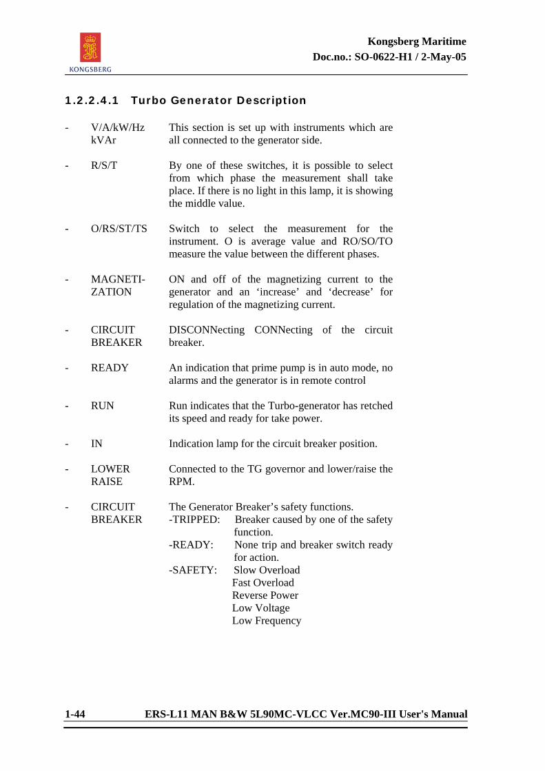
1.2.2.4.1 Turbo Generator Description - V/A/kW/Hz
kVAr This section is set up with instruments which are all connected to the generator side.
- R/S/T By one of these switches, it is possible to select
from which phase the measurement shall take place. If there is no light in this lamp, it is showing the middle value.
- O/RS/ST/TS Switch to select the measurement for the
instrument. O is average value and RO/SO/TO measure the value between the different phases.
- MAGNETI-
ZATION ON and off of the magnetizing current to the generator and an ‘increase’ and ‘decrease’ for regulation of the magnetizing current.
- CIRCUIT
BREAKER DISCONNecting CONNecting of the circuit breaker.
- READY An indication that prime pump is in auto mode, no
alarms and the generator is in remote control - RUN Run indicates that the Turbo-generator has retched
its speed and ready for take power. - IN Indication lamp for the circuit breaker position. - LOWER
RAISE Connected to the TG governor and lower/raise the RPM.
- CIRCUIT
BREAKER The Generator Breaker’s safety functions. -TRIPPED: Breaker caused by one of the safety
function. -READY: None trip and breaker switch ready
for action. -SAFETY: Slow Overload Fast Overload Reverse Power Low Voltage Low Frequency
Kongsberg Maritime Doc.no.: SO-0622-H1 / 2-May-05
ERS-L11 MAN B&W 5L90MC-VLCC Ver.MC90-III User's Manual 1-45
1.2.2.5 Shaft Generator/Motor A PTI/PTO arrangement consisting of a combined shaft motor/generator with converter and compensator included. In PTI mode the “shaft motor” is supplied from the diesel generators as well as the turbo-generator. In PTO mode the “shaft generator” supplies the main bus bar II.
Kongsberg Maritime Doc.no.: SO-0622-H1 / 2-May-05
1-46 ERS-L11 MAN B&W 5L90MC-VLCC Ver.MC90-III User's Manual
1.2.2.5.1 Shaft Generator/Motor Panel Description - V/A/kW/Hz
kVAr This section is set up with instruments which are all connected to the generator side.
- R/S/T By one of these switches, it is possible to select
from which phase the measurement shall take place. If there is no light in this lamp, it is showing the middle value.
- O/RS/ST/TS Switch to select the measurement for the
instrument. O is average value and RO/SO/TO measure the value between the different phases.
- PTI/PTO MODE
Switch to select between PTI/PTO operation.
- MAGNETI-
ZATION ON and off of the magnetizing current to the generator and an ‘increase’ and ‘decrease’ for regulation of the magnetizing current.
- CIRCUIT BREAKER
DISCONNecting CONNecting of the circuit breaker.
- READY An indication that air to the clutch is present, no
alarms and clutch control is set to remote control. - RUN Run indicates that the PTI/PTO is running and
ready to take power in/out. - IN Indication lamp for the circuit breaker position. - DECREASE
INCREASE Increase/decrease the frequency converter speed.
- CIRCUIT
BREAKER The Generator Breaker’s safety functions. -TRIPPED: Breaker caused by one of the safety
function. -READY: None trip and breaker switch ready
for action. -SAFETY: Slow Overload Fast Overload Reverse Power Low Voltage Low Frequency
- FUSE
BREAKER Breakers for Bow Thruster and Deck Machinery with ampere meter.
- BUS TIE Breaker for connection of main bus bars.
Kongsberg Maritime Doc.no.: SO-0622-H1 / 2-May-05
ERS-L11 MAN B&W 5L90MC-VLCC Ver.MC90-III User's Manual 1-47
1.2.2.6 Synchronizing Volt and frequency readings of the main bus bar are available on the panel. Together with speed adjustment, the operator is allowed to connect a generator without verification of synchronizing. The synchronizing section contains a double-volt meter, a synchro-indicator and a double-frequency meter. A selector switch enables readings of voltage, difference- voltage and frequency of all the generators. A mega-ohm meter indicates possible earth leakage on the main bus bars. A shore-connecting device enables monitoring of the phase sequence and cross-coupling of the leads (if needed) before the shore connection is made. 1.2.2.6.1 Synchronizing Panel Description - V/Hz This section is set up with instruments which are
all connected to the generator side and to the main bus bar.
- O / DG1 / DG2
/SG Selectable switch to enable readings of voltage and frequency between the bus bar and the different sources. O is the Bus bar.
- O/RO/SO/TO Switch to select the measurement for the
instrument. O is average value and RO/SO/TO measure the value between the different phases.
- CIRCUIT
BREAKER DISCONNecting/CONNecting of the circuit breaker (Shore connection).
- IN Indication lamp for the circuit breaker position. - WRONG
ROTATION ON SHORE
Wrong rotation on shore sources. Turning the phase of the shore sources. Turning on the shore-connection should be clock-wise.
- -
SHORE CON SEMI AUTO
Indication lamp for the shore connection circuit. Automatic synchronizing of generators, except for the voltage and frequency which has be done manually; Select generator, adjust voltage and frequency, when these are within actual limits, the generator connects to the bus bar.
Kongsberg Maritime Doc.no.: SO-0622-H1 / 2-May-05
1-48 ERS-L11 MAN B&W 5L90MC-VLCC Ver.MC90-III User's Manual
1.2.2.7 Shore Power Shore connection can only be activated when ME rpm is set to zero by the “STOP SHIP” function. When the shore cable is connected, the electric phase will be selected at random by the simulator. A wrong sequence is indicated by a lit red lamp. Activating the button on the Shore Power Section of the switchboard interchanges the cables, and the light will disappear. When the electric phase is correct, the shore power can be connected to the main bus bar. 1.2.2.8 Miscellaneous The miscellaneous section contains instruments that give information of the temperature in the control and engine room and power consumption of the selected pumps. There is a static converter which controls the connected pumps on the ship. Use of this converter can give the pumps a higher efficiency. There is a fire monitor with indication and activating of fire fighting equipment.
Kongsberg Maritime Doc.no.: SO-0622-H1 / 2-May-05
ERS-L11 MAN B&W 5L90MC-VLCC Ver.MC90-III User's Manual 1-49
1.3 Engine Room Systems 1.3.1 General Information Alarms Always accept alarms before starting a system (flashing lamps indicate alarms not accepted). Engine Room Systems It is possible to run some of the systems as single, isolated units. No related systems are then required to be operational, because external parameters are generated by the computer. Isolation of a system is done by selecting it on the variable list (see functional description for further information). Fault If a fault has been detected, it has probably been generated by instructor. To rectify suspected faults: (Example from ME Fresh water system). Fresh water pump no 1 running, and no 2 in stand-by. Fresh water pump 2 starts after drop in coolant pressure. Suspected fault : Worn fresh water pump no 1. Malfunctions In the different MD pictures there are one or more letters “M”, clicking on one of these letters with tracker-ball centre button displays a window with malfunctions connected to actual group. (Letters are coloured yellow when faults are activated.) When in operator mode (student), only the possible malfunctions are displayed. In instructor mode, the display shows active malfunctions and their settings. On the line where the suspected fault is, click with RIGHT tracker-ball button to rectify fault. A prompt on the screen will verify “repair” attempt. Having done this, pump should now be ready to be restarted.
Kongsberg Maritime Doc.no.: SO-0622-H1 / 2-May-05
1-50 ERS-L11 MAN B&W 5L90MC-VLCC Ver.MC90-III User's Manual
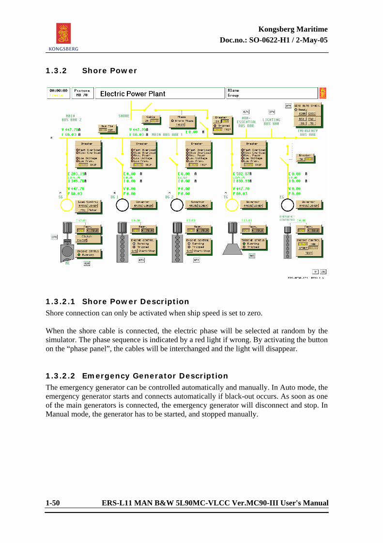
1.3.2 Shore Power
1.3.2.1 Shore Power Description Shore connection can only be activated when ship speed is set to zero. When the shore cable is connected, the electric phase will be selected at random by the simulator. The phase sequence is indicated by a red light if wrong. By activating the button on the “phase panel”, the cables will be interchanged and the light will disappear. 1.3.2.2 Emergency Generator Description The emergency generator can be controlled automatically and manually. In Auto mode, the emergency generator starts and connects automatically if black-out occurs. As soon as one of the main generators is connected, the emergency generator will disconnect and stop. In Manual mode, the generator has to be started, and stopped manually.
Kongsberg Maritime Doc.no.: SO-0622-H1 / 2-May-05
ERS-L11 MAN B&W 5L90MC-VLCC Ver.MC90-III User's Manual 1-51
<This page is intentionally left blank>
Kongsberg Maritime Doc.no.: SO-0622-H1 / 2-May-05
1-52 ERS-L11 MAN B&W 5L90MC-VLCC Ver.MC90-III User's Manual
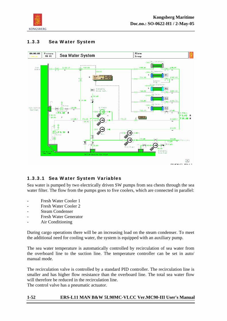
1.3.3 Sea Water System
1.3.3.1 Sea Water System Variables Sea water is pumped by two electrically driven SW pumps from sea chests through the sea water filter. The flow from the pumps goes to five coolers, which are connected in parallel: - Fresh Water Cooler 1 - Fresh Water Cooler 2 - Steam Condenser - Fresh Water Generator - Air Conditioning During cargo operations there will be an increasing load on the steam condenser. To meet the additional need for cooling water, the system is equipped with an auxiliary pump. The sea water temperature is automatically controlled by recirculation of sea water from the overboard line to the suction line. The temperature controller can be set in auto/ manual mode. The recirculation valve is controlled by a standard PID controller. The recirculation line is smaller and has higher flow resistance than the overboard line. The total sea water flow will therefore be reduced in the recirculation line. The control valve has a pneumatic actuator.
Kongsberg Maritime Doc.no.: SO-0622-H1 / 2-May-05
ERS-L11 MAN B&W 5L90MC-VLCC Ver.MC90-III User's Manual 1-53
The standard valve actuator can be changed with a motor driven actuator. The motor control interface is modelled as follows: - 100 % controller signal gives full opening speed - 50 % controller signal gives zero speed - 0 % controller signal gives full closing speed Studies comparing the dynamic behaviour of the standard actuator system with the motor actuator system are recommended. The SW pumps can be used as emergency bilge pumps. A separate pipe is provided for this operation. The fire pump has a separate suction from the sea chest. The Sea Water system has an emergency suction main SW valve. The Air condition is ready for use when the following criteria is fulfilled: - Valve to aircondition SW cooler is open. - The differential pressure (difference between the inlet SW pressure to coolers and the SW pressure outside the hull (mWC)) is more than 0.5 bar.
Kongsberg Maritime Doc.no.: SO-0622-H1 / 2-May-05
1-54 ERS-L11 MAN B&W 5L90MC-VLCC Ver.MC90-III User's Manual
1.3.4 Fresh Water System
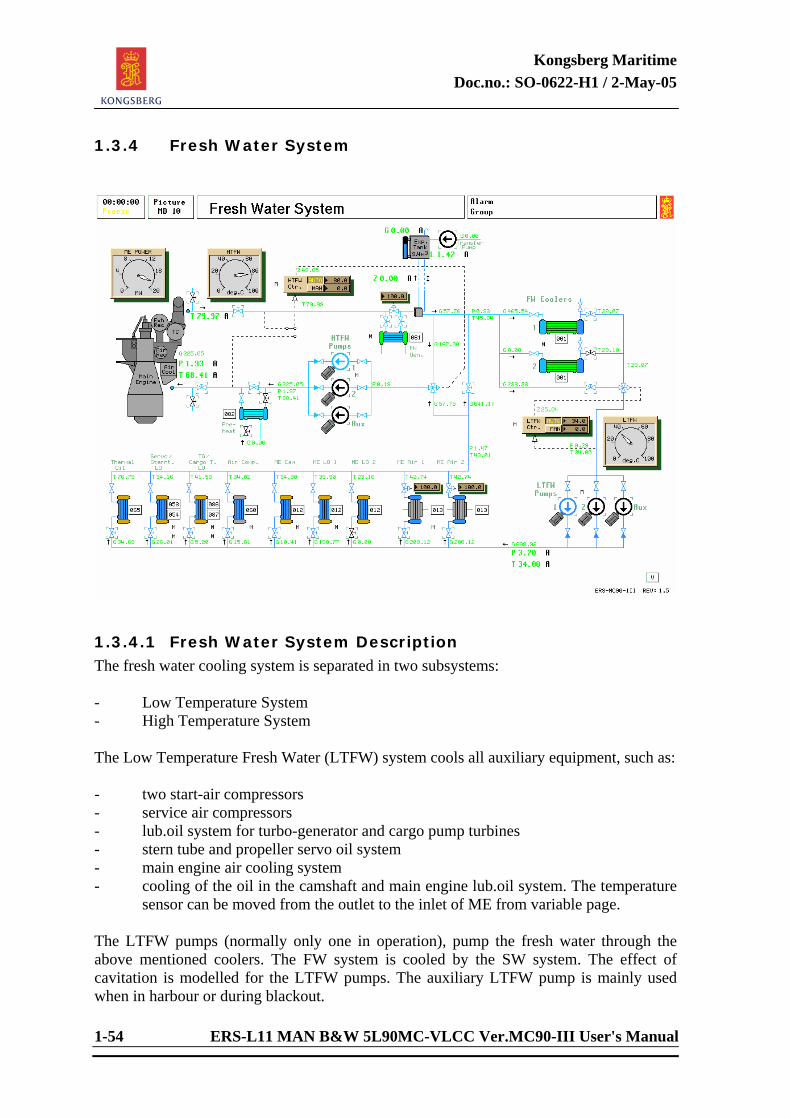
1.3.4.1 Fresh Water System Description The fresh water cooling system is separated in two subsystems: - Low Temperature System - High Temperature System The Low Temperature Fresh Water (LTFW) system cools all auxiliary equipment, such as: - two start-air compressors - service air compressors - lub.oil system for turbo-generator and cargo pump turbines - stern tube and propeller servo oil system - main engine air cooling system - cooling of the oil in the camshaft and main engine lub.oil system. The temperature sensor can be moved from the outlet to the inlet of ME from variable page. The LTFW pumps (normally only one in operation), pump the fresh water through the above mentioned coolers. The FW system is cooled by the SW system. The effect of cavitation is modelled for the LTFW pumps. The auxiliary LTFW pump is mainly used when in harbour or during blackout.
Kongsberg Maritime Doc.no.: SO-0622-H1 / 2-May-05
ERS-L11 MAN B&W 5L90MC-VLCC Ver.MC90-III User's Manual 1-55
The fresh water temperature in the LTFW system is controlled by a PID controller, which actuates a three-way mixing valve, placed after the two fresh water coolers. This controller can be operated in manual or auto mode. The controller input signal is given by the temperature before the LTFW pumps. From the LT/HT junction, some of the LTFW is led directly to the FW coolers, while some is led to the HTFW loop. The High Temperature fresh water cools the liners of the main engine. Some of the excessive heat is used for heating the fresh water generator. The fresh water through the main engine is driven by a pair of HTFW pumps, of which only one is normally in operation. If the HTFW pumps stop, a small cooling medium flow will still be present as long as one of the LTFW pumps is running. If the main engine has been stopped for a long period of time, it is required to permit the HTFW flow to pass the preheater, which is supplied with steam. The effect of cavitation is modelled for the HTFW pumps. The auxiliary HTFW pump is mainly used when in harbour or during blackout. The HTFW system is controlled by a PID controller, which operates a three way mixing valve, mixing hot water from main engine outlet with cold water from the LT/HT junction. The temperature sensor may be moved from the outlet to the inlet of ME. If the FW of the main engine outlet is at boiling point, fresh water evaporation is simulated. The resulting low water level in the expansion tank leads to low pressure in the fresh water system. The HTFW pumps are especially liable to cavitate under these low pressure conditions, causing a reduction in ME cooling. The static pressure in the fresh water system is given by the water level in the fresh water expansion tank. There is a small constant consumption of fresh water due to leakage and evaporation. The expansion tank must be filled periodically. In bad weather, unsteady expansion tank level is simulated, and false alarms may arise. Actuator type can be changed from variable page.
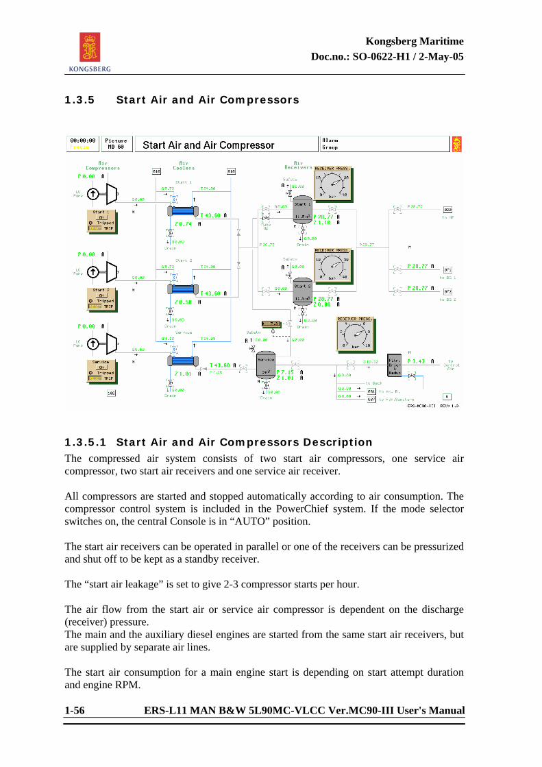
Kongsberg Maritime Doc.no.: SO-0622-H1 / 2-May-05
1-56 ERS-L11 MAN B&W 5L90MC-VLCC Ver.MC90-III User's Manual
1.3.5 Start Air and Air Compressors
1.3.5.1 Start Air and Air Compressors Description The compressed air system consists of two start air compressors, one service air compressor, two start air receivers and one service air receiver. All compressors are started and stopped automatically according to air consumption. The compressor control system is included in the PowerChief system. If the mode selector switches on, the central Console is in “AUTO” position. The start air receivers can be operated in parallel or one of the receivers can be pressurized and shut off to be kept as a standby receiver. The “start air leakage” is set to give 2-3 compressor starts per hour. The air flow from the start air or service air compressor is dependent on the discharge (receiver) pressure. The main and the auxiliary diesel engines are started from the same start air receivers, but are supplied by separate air lines. The start air consumption for a main engine start is depending on start attempt duration and engine RPM.
Kongsberg Maritime Doc.no.: SO-0622-H1 / 2-May-05
ERS-L11 MAN B&W 5L90MC-VLCC Ver.MC90-III User's Manual 1-57
The start air consumption for the diesel generators is constant for each start. The service air receiver supplies air to the control equipment in the engine room and to deck work purposes and soot blowing of exhaust boiler. The air to the control equipment is filtered and dried and its pressure reduced by a pressure reduction valve (part of the filter/drier assembly). All main control valves included in the simulated ship machinery are assumed to be air actuated. As the control air pressure is reduced, these valves will operate slower and the effective actuator time constants are increased. Various control loop problems may arise at low control air pressure. Some of the loops will be slow and stable, others conditionally unstable (unstable in an intermediate range). If the service air compressor fails, make-up air can be taken from the start air receivers. An automatic air reduction control valve reduces the make-up gradually at increasing service air pressure. The safety valves for the start air and service air receivers open at approximately 32 bar and 8 bar, respectively. The compressors are monitored by an independent local safety system. All compressors are cooled by water. High air outlet temperature is indicated by a red alarm light on the compressor panel. If the air temperature rises above an upper limit, the compressor will trip. The air receivers and the air coolers will gradually fill with water, depending on compressed air production. The receivers and coolers must be drained regularly. When operating the drain valves on the local panel, steady light indicates that water is being drained while flashing light indicates that dry air is blowing. Too much water in the start air receivers will lead to reduced starting capacity and possibilities for main engine “water strike” at start of engine. Too much water in the service air receiver will lead to problems with the oil viscosity controller. If the intermediate air cooler is not drained regularly, it will gradually be filled with water and overheat.
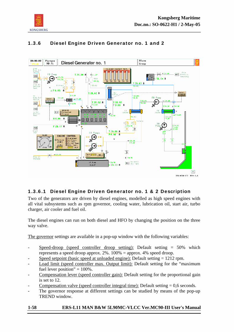
Kongsberg Maritime Doc.no.: SO-0622-H1 / 2-May-05
1-58 ERS-L11 MAN B&W 5L90MC-VLCC Ver.MC90-III User's Manual
1.3.6 Diesel Engine Driven Generator no. 1 and 2
1.3.6.1 Diesel Engine Driven Generator no. 1 & 2 Description Two of the generators are driven by diesel engines, modelled as high speed engines with all vital subsystems such as rpm governor, cooling water, lubrication oil, start air, turbo charger, air cooler and fuel oil. The diesel engines can run on both diesel and HFO by changing the position on the three way valve. The governor settings are available in a pop-up window with the following variables: - Speed-droop (speed controller droop setting): Default setting = 50% which
represents a speed droop approx. 2%. 100% = approx. 4% speed droop. - Speed setpoint (basic speed at unloaded engine): Default setting = 1212 rpm. - Load limit (speed controller max. Output limit): Default setting for the “maximum
fuel lever position” = 100%. - Compensation lever (speed controller gain): Default setting for the proportional gain
is set to 12. - Compensation valve (speed controller integral time): Default setting = 0,6 seconds. - The governor response at different settings can be studied by means of the pop-up
TREND window.
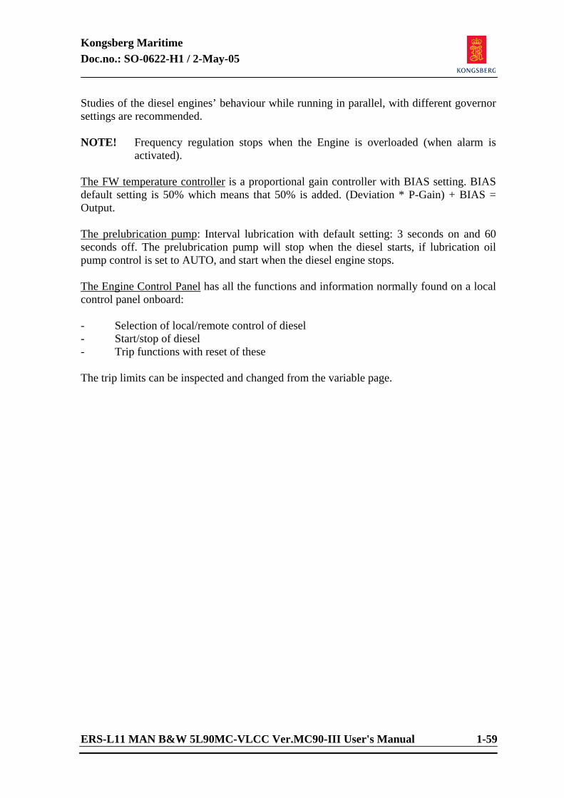
Kongsberg Maritime Doc.no.: SO-0622-H1 / 2-May-05
ERS-L11 MAN B&W 5L90MC-VLCC Ver.MC90-III User's Manual 1-59
Studies of the diesel engines’ behaviour while running in parallel, with different governor settings are recommended. NOTE! Frequency regulation stops when the Engine is overloaded (when alarm is
activated). The FW temperature controller is a proportional gain controller with BIAS setting. BIAS default setting is 50% which means that 50% is added. (Deviation * P-Gain) + BIAS = Output. The prelubrication pump: Interval lubrication with default setting: 3 seconds on and 60 seconds off. The prelubrication pump will stop when the diesel starts, if lubrication oil pump control is set to AUTO, and start when the diesel engine stops. The Engine Control Panel has all the functions and information normally found on a local control panel onboard: - Selection of local/remote control of diesel - Start/stop of diesel - Trip functions with reset of these The trip limits can be inspected and changed from the variable page.
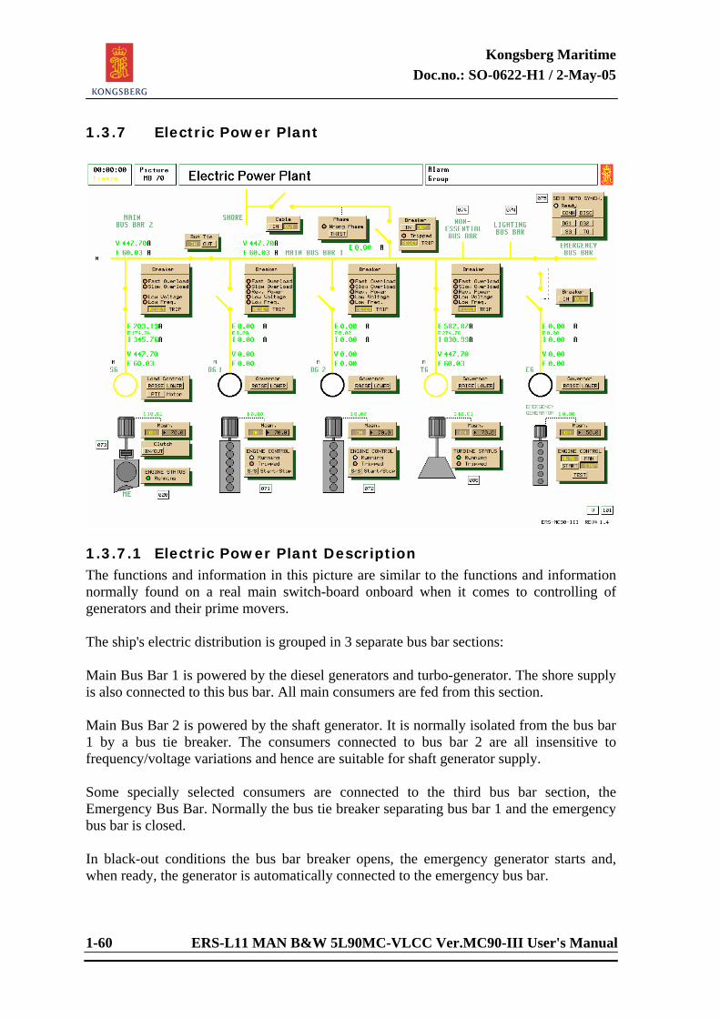
Kongsberg Maritime Doc.no.: SO-0622-H1 / 2-May-05
1-60 ERS-L11 MAN B&W 5L90MC-VLCC Ver.MC90-III User's Manual
1.3.7 Electric Power Plant
1.3.7.1 Electric Power Plant Description The functions and information in this picture are similar to the functions and information normally found on a real main switch-board onboard when it comes to controlling of generators and their prime movers. The ship's electric distribution is grouped in 3 separate bus bar sections: Main Bus Bar 1 is powered by the diesel generators and turbo-generator. The shore supply is also connected to this bus bar. All main consumers are fed from this section. Main Bus Bar 2 is powered by the shaft generator. It is normally isolated from the bus bar 1 by a bus tie breaker. The consumers connected to bus bar 2 are all insensitive to frequency/voltage variations and hence are suitable for shaft generator supply. Some specially selected consumers are connected to the third bus bar section, the Emergency Bus Bar. Normally the bus tie breaker separating bus bar 1 and the emergency bus bar is closed. In black-out conditions the bus bar breaker opens, the emergency generator starts and, when ready, the generator is automatically connected to the emergency bus bar.
Kongsberg Maritime Doc.no.: SO-0622-H1 / 2-May-05
ERS-L11 MAN B&W 5L90MC-VLCC Ver.MC90-III User's Manual 1-61
The load of electric motors is generally not modelled in detail. Total electric load is computed by adding the rated power of all running motors and then correcting this sum with respect to the present line voltage/frequency. The typical current increase during the starting phase of an asynchronous motor is modelled. Some of the pumps are modelled in more detail. These can be operated at variable speed. The electric load is computed from hydraulic load based on pump characteristics and operational conditions. Some electric loads have no influence apart from that on the power generating system, like general consumers (lighting, heating, etc.) specified by the instructor. A static frequency converter is included. When active, it will convert the bus bar frequency to a frequency specified by the converter’s setpoint. The speed of the variable speed pumps will follow the output frequency. No variation in the electric slip is modelled, so pump speed is strictly proportional to frequency. The cable from shore can only be connected in port (no speed). The ship speed should be kept to zero by “STOP SHIP” function (mooring condition). At cable connection, the electric phase will be chosen at random. The phase sequence is indicated by a rotating light wheel. Clockwise rotation is correct. Pressing on “WRONG PHASE” light simulates a corrective phase change. For a smooth transfer, shore power can be synchronized to the ship’s electric net by adjusting the speed/phase of the ship generators before the generators are finally disconnected. The frequency and the load sharing between the generators are given through the joint effect of the speed governors. By using the lower/raise switches on the Load Control, the desired load sharing and network frequency can be obtained. Due to the difference in the torque characteristics of the generators, it will not be possible to keep the same load sharing over the whole power range (except by manual readjustment or by control action from the PowerChief system). The bus bar voltage and reactive load sharing between generators can be adjusted by trimming the generator magnetization. The main circuit breakers connecting each generator to the electric bus bar are disconnected automatically for the following reasons: - connection shock - overload current - reverse current - low voltage - low frequency
Kongsberg Maritime Doc.no.: SO-0622-H1 / 2-May-05
1-62 ERS-L11 MAN B&W 5L90MC-VLCC Ver.MC90-III User's Manual
- bus bar shock The reverse current protection takes place if the generator's prime mover (diesel engine or steam turbine) is shut down. The generator will then function as an electric motor driving the steam turbine or diesel engine, if it is not disconnected. “Bus bar shock” is most likely caused by a very rough connection to one of the other generators. Semi Synchronizing is a manual synchronizing to main bus. By selecting the generator to be connected by pressing the corresponding button and then manually adjust voltage and frequency until synchronization (READY lamp is lit), the generator is ready to connect. Connecting the generator to main bus is carried out by the CONNECT button. (Generator to be connected has to be selected and READY lamp must be lit.)
Kongsberg Maritime Doc.no.: SO-0622-H1 / 2-May-05
ERS-L11 MAN B&W 5L90MC-VLCC Ver.MC90-III User's Manual 1-63
<This page is intentionally left blank>
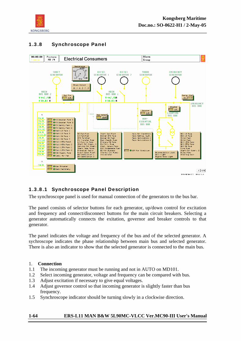
Kongsberg Maritime Doc.no.: SO-0622-H1 / 2-May-05
1-64 ERS-L11 MAN B&W 5L90MC-VLCC Ver.MC90-III User's Manual
1.3.8 Synchroscope Panel
1.3.8.1 Synchroscope Panel Description The synchroscope panel is used for manual connection of the generators to the bus bar. The panel consists of selector buttons for each generator, up/down control for excitation and frequency and connect/disconnect buttons for the main circuit breakers. Selecting a generator automatically connects the exitation, governor and breaker controls to that generator. The panel indicates the voltage and frequency of the bus and of the selected generator. A sychroscope indicates the phase relationship between main bus and selected generator. There is also an indicator to show that the selected generator is connected to the main bus. 1. Connection 1.1 The incoming generator must be running and not in AUTO on MD101. 1.2 Select incoming generator, voltage and frequency can be compared with bus. 1.3 Adjust excitation if necessary to give equal voltages. 1.4 Adjust governor control so that incoming generator is slightly faster than bus
frequency. 1.5 Synchroscope indicator should be turning slowly in a clockwise direction.
Kongsberg Maritime Doc.no.: SO-0622-H1 / 2-May-05
ERS-L11 MAN B&W 5L90MC-VLCC Ver.MC90-III User's Manual 1-65
1.6 Connect breaker when the top synschroscope indicator is lit. The breaker connected light will show that the generator is now connected to the bus.
1.7 Increase the governor speed to give the incoming generator some load. 1.8 To manually share the load equally use the governor controls on MD70. 2. Disconnection 2.1 Ensure generator to be disconnected is not in AUTO on MD101 2.2 Use governor controls on MD70 to reduce the load on outgoing generator to zero. 2.3 Select outgoing generator. 2.4 Disconnect, breaker connected light goes out.
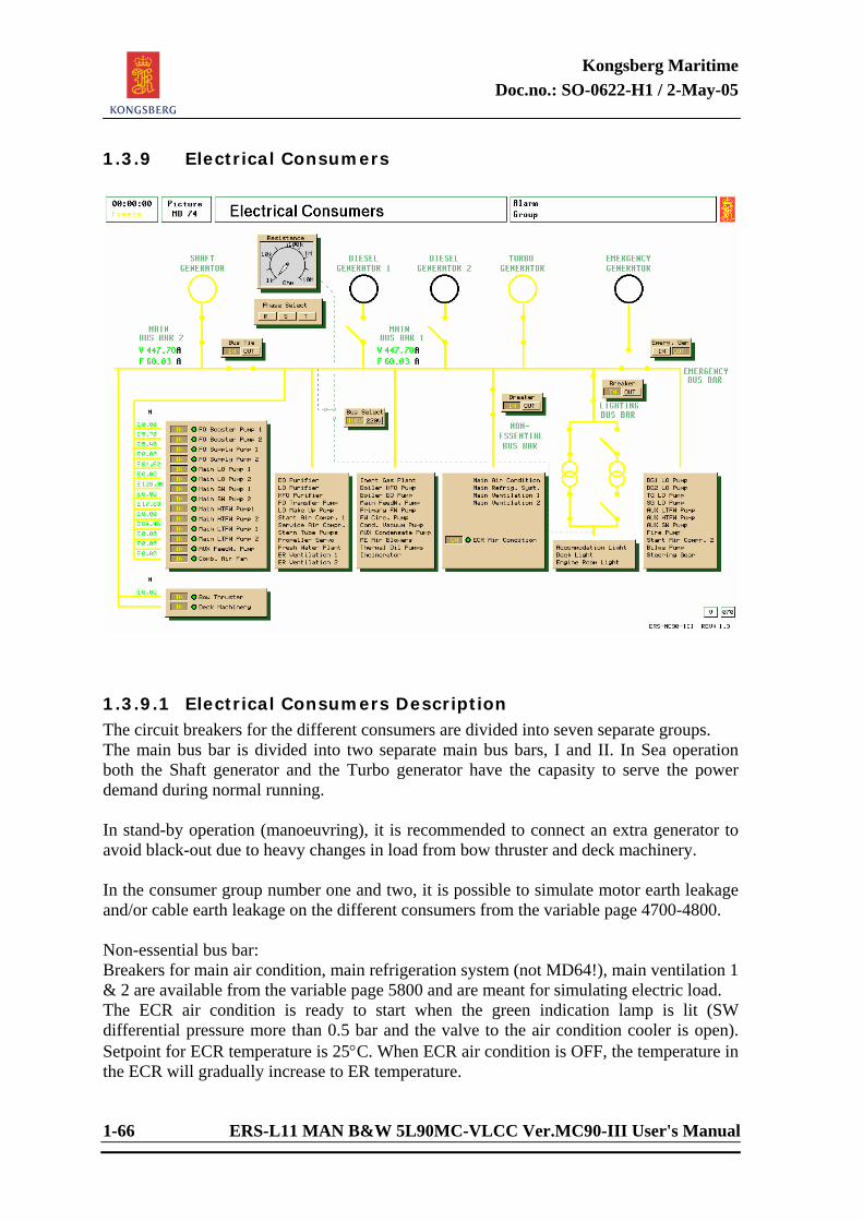
Kongsberg Maritime Doc.no.: SO-0622-H1 / 2-May-05
1-66 ERS-L11 MAN B&W 5L90MC-VLCC Ver.MC90-III User's Manual
1.3.9 Electrical Consumers
1.3.9.1 Electrical Consumers Description The circuit breakers for the different consumers are divided into seven separate groups. The main bus bar is divided into two separate main bus bars, I and II. In Sea operation both the Shaft generator and the Turbo generator have the capasity to serve the power demand during normal running. In stand-by operation (manoeuvring), it is recommended to connect an extra generator to avoid black-out due to heavy changes in load from bow thruster and deck machinery. In the consumer group number one and two, it is possible to simulate motor earth leakage and/or cable earth leakage on the different consumers from the variable page 4700-4800. Non-essential bus bar: Breakers for main air condition, main refrigeration system (not MD64!), main ventilation 1 & 2 are available from the variable page 5800 and are meant for simulating electric load. The ECR air condition is ready to start when the green indication lamp is lit (SW differential pressure more than 0.5 bar and the valve to the air condition cooler is open). Setpoint for ECR temperature is 25°C. When ECR air condition is OFF, the temperature in the ECR will gradually increase to ER temperature.
Kongsberg Maritime Doc.no.: SO-0622-H1 / 2-May-05
ERS-L11 MAN B&W 5L90MC-VLCC Ver.MC90-III User's Manual 1-67
The ER ventilation 1 and 2 is started by pressing the corresponding buttons. The consumers will be disconnected by the non essential bus-bar breaker at overload on generators to avoid black-out. Total effect for these consumers is approximately 150 kW. Lightning bus bar: To be able to connect the Lightning Bus Circuit Breaker, the breakers to the transformer(s) have to be connected. Carried out from the variable page 7007 or from the Main Switch board panel. Electric earth leakage can be set on the accommodation, deck and engine room light from the malfunction page. There is included an instrument for measuring resistance against earth. Selecting of bus bar (440/220) and phase (R,S,T) by pressing the corresponding buttons.
Kongsberg Maritime Doc.no.: SO-0622-H1 / 2-May-05
1-68 ERS-L11 MAN B&W 5L90MC-VLCC Ver.MC90-III User's Manual
The groups are as follows: - Bow Thruster - Main Air Condition - Deck machinery - Main Refrig. System - Main Ventilation 1 - FO Booster Pump 1 - Main Ventilation 2 - FO Booster Pump 2 - ECR Air Condition - FO Supply Pump 1 - FO Supply Pump 2 - Accommodation Light - Main LO Pump 1 - Deck Light - Main LO Pump 2 - Engine Room Light - Main SW Pump 1 - Main SW Pump 2 - DG 1 LO Pump - Main HTFW Pump 1 - DG 2 LO Pump - Main HTFW Pump 2 - TG LO Pump - Main LTFW Pump 1 - SG LO Pump - Main LTFW Pump 2 - Aux LTFW Pump - Aux FeedW. Pump - Aux HTFW Pump - Comb. Air Fan - Aux SW Pump - Fire Pump - DO Purifier - Start Air Compr. 2 - LO Purifier - Bilge Pump - HFO Purifier - Steering Gear - FO Transfer Pump - LO Make Up Pump - Start Air Compr. 1 - Service Air Compr. - Stern Tube Pumps - Propeller Servo - Fresh Water Plant - ER Ventilation 1 - ER Ventilation 2 - Inert Gas Plant - Boiler HFO Pump - Boiler DO Pump - Main Feed Water Pump - Primary FW Pump - FW Circ. Pump - Cond. Vacuum Pump - Aux Condensate Pump - ME Air Blower - Thermal Oil Pump - Incinerator
Kongsberg Maritime Doc.no.: SO-0622-H1 / 2-May-05
ERS-L11 MAN B&W 5L90MC-VLCC Ver.MC90-III User's Manual 1-69
<This page is intentionally left blank>
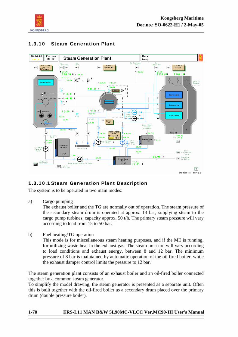
Kongsberg Maritime Doc.no.: SO-0622-H1 / 2-May-05
1-70 ERS-L11 MAN B&W 5L90MC-VLCC Ver.MC90-III User's Manual
1.3.10 Steam Generation Plant
1.3.10.1 Steam Generation Plant Description The system is to be operated in two main modes: a) Cargo pumping The exhaust boiler and the TG are normally out of operation. The steam pressure of
the secondary steam drum is operated at approx. 13 bar, supplying steam to the cargo pump turbines, capacity approx. 50 t/h. The primary steam pressure will vary according to load from 15 to 50 bar.
b) Fuel heating/TG operation This mode is for miscellaneous steam heating purposes, and if the ME is running,
for utilizing waste heat in the exhaust gas. The steam pressure will vary according to load conditions and exhaust energy, between 8 and 12 bar. The minimum pressure of 8 bar is maintained by automatic operation of the oil fired boiler, while the exhaust damper control limits the pressure to 12 bar.
The steam generation plant consists of an exhaust boiler and an oil-fired boiler connected together by a common steam generator. To simplify the model drawing, the steam generator is presented as a separate unit. Often this is built together with the oil-fired boiler as a secondary drum placed over the primary drum (double pressure boiler).
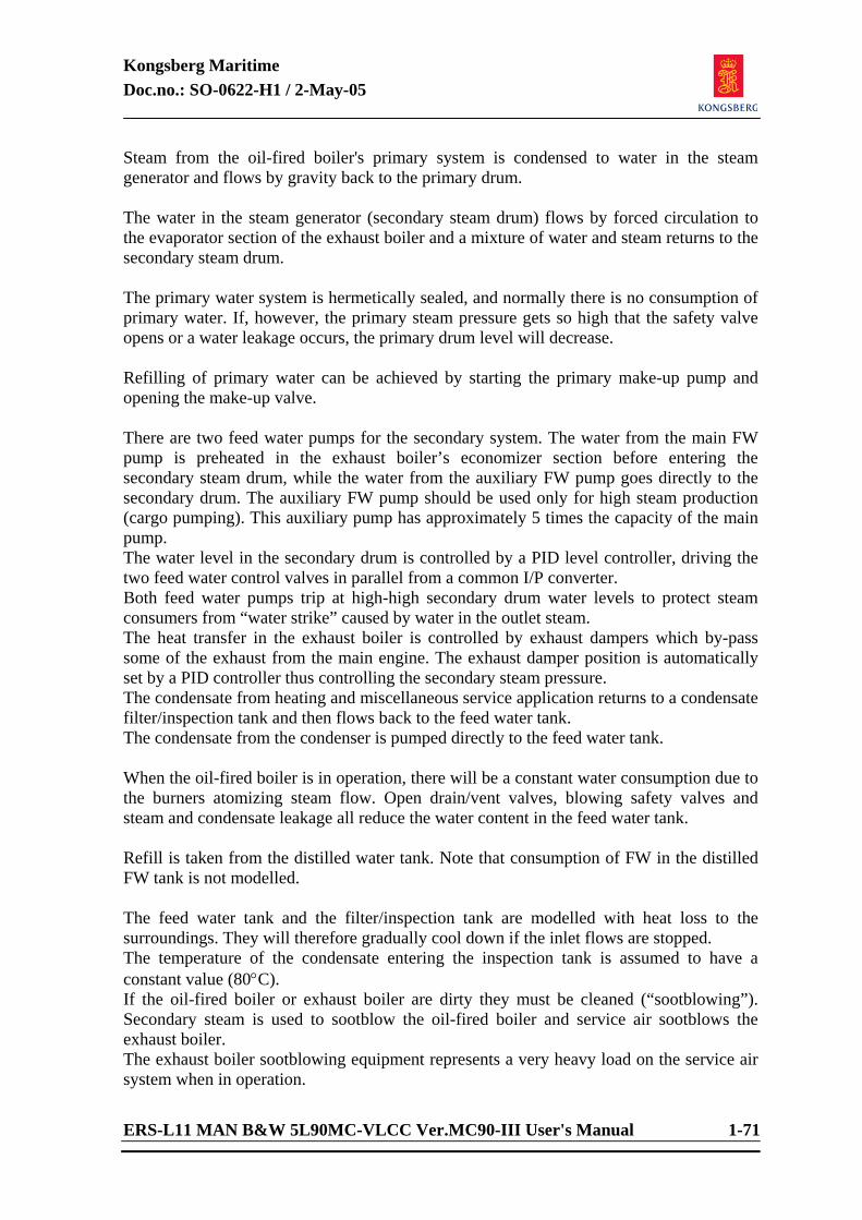
Kongsberg Maritime Doc.no.: SO-0622-H1 / 2-May-05
ERS-L11 MAN B&W 5L90MC-VLCC Ver.MC90-III User's Manual 1-71
Steam from the oil-fired boiler's primary system is condensed to water in the steam generator and flows by gravity back to the primary drum. The water in the steam generator (secondary steam drum) flows by forced circulation to the evaporator section of the exhaust boiler and a mixture of water and steam returns to the secondary steam drum. The primary water system is hermetically sealed, and normally there is no consumption of primary water. If, however, the primary steam pressure gets so high that the safety valve opens or a water leakage occurs, the primary drum level will decrease. Refilling of primary water can be achieved by starting the primary make-up pump and opening the make-up valve. There are two feed water pumps for the secondary system. The water from the main FW pump is preheated in the exhaust boiler’s economizer section before entering the secondary steam drum, while the water from the auxiliary FW pump goes directly to the secondary drum. The auxiliary FW pump should be used only for high steam production (cargo pumping). This auxiliary pump has approximately 5 times the capacity of the main pump. The water level in the secondary drum is controlled by a PID level controller, driving the two feed water control valves in parallel from a common I/P converter. Both feed water pumps trip at high-high secondary drum water levels to protect steam consumers from “water strike” caused by water in the outlet steam. The heat transfer in the exhaust boiler is controlled by exhaust dampers which by-pass some of the exhaust from the main engine. The exhaust damper position is automatically set by a PID controller thus controlling the secondary steam pressure. The condensate from heating and miscellaneous service application returns to a condensate filter/inspection tank and then flows back to the feed water tank. The condensate from the condenser is pumped directly to the feed water tank. When the oil-fired boiler is in operation, there will be a constant water consumption due to the burners atomizing steam flow. Open drain/vent valves, blowing safety valves and steam and condensate leakage all reduce the water content in the feed water tank. Refill is taken from the distilled water tank. Note that consumption of FW in the distilled FW tank is not modelled. The feed water tank and the filter/inspection tank are modelled with heat loss to the surroundings. They will therefore gradually cool down if the inlet flows are stopped. The temperature of the condensate entering the inspection tank is assumed to have a constant value (80°C). If the oil-fired boiler or exhaust boiler are dirty they must be cleaned (“sootblowing”). Secondary steam is used to sootblow the oil-fired boiler and service air sootblows the exhaust boiler. The exhaust boiler sootblowing equipment represents a very heavy load on the service air system when in operation.
Kongsberg Maritime Doc.no.: SO-0622-H1 / 2-May-05
1-72 ERS-L11 MAN B&W 5L90MC-VLCC Ver.MC90-III User's Manual
1.3.11 Boiler Combustion
1.3.11.1 Boiler Combustion Description A safety system cuts off the fuel oil supply to the boiler by closing the trip valve at the following conditions: - stopped combustion air fan - low primary water level - low steam atomizing pressure - no flame indication, both burners - furnace explosion (missing purge) - furnace explosion (DO operation) Automatic combustion control with diesel oil is safe only when small burner nozzles are used. No atomizing steam is needed at diesel oil operation. The combustion control system consists of a master controller and two slave controllers, and also an oxygen controller. Its objectives are: - to control the oil flow to the boiler to keep the secondary steam pressure as close to
the pressure setpoint as possible. - to supply correct amount of air relative to oil at any time to ensure efficient and safe combustion.
Kongsberg Maritime Doc.no.: SO-0622-H1 / 2-May-05
ERS-L11 MAN B&W 5L90MC-VLCC Ver.MC90-III User's Manual 1-73
The master controller generates an energy signal to a “high/low” select logic box. This computes the setpoints for the desired oil and air flow for the slave controllers. The master controller is a PID acting controller with feed forward from steam flow out of secondary steam drum and (optionally) primary steam pressure. The slave controllers are fully acting PID controllers. They must be set in manual mode during start-up. The function of the “high/low” select logic is to ensure that air command increases before oil command at load increase and that oil command is reduced before air command at load reduction. This is a standard logic block found in most boiler control schemes. Before start-up of the boiler the furnace must be air purged. The purging period is set long enough to change the air volume in the furnace about 4 times in accordance with classification societies safety requirements. The automatic lighting sequence is as follows (the sequence is not modelled in detail). - air register is opened - electric spark ignitor turned on - oil shut off valve opened If the flame detector does not see flame within approximately 6 seconds, the oil shut off valve and the air register are closed. Flashing light is indicating burner fault. When the burner is in operation the flame will be “blown out” if there is too much air compared to oil and it will be “killed” by lack of air if there is too much oil compared to air. Burner Management The boiler system includes a simple but efficient burner control system. It starts and stops burner no 2 (slave burner) according to need. It is in function only if burner no 1 (base burner) is on. The slave burner is started if the secondary steam pressure is under low limit and is stopped if the pressure is over high limit. To avoid burner cycling (frequent start and stop of burners caused by the mutual influence between combustion control and burner management), there is a time delay between start and stop. It is recommended to try several values of pressure limits and time delays to demonstrate its effect on the overall combustion control performance. If a burner fault occurs, the burner is shut down and the “BURNER ON” light is flashing. The cause of a burner fault is found by inspecting the trip code:
Kongsberg Maritime Doc.no.: SO-0622-H1 / 2-May-05
1-74 ERS-L11 MAN B&W 5L90MC-VLCC Ver.MC90-III User's Manual
- too much oil during ignition - too much air during ignition - unstable flame caused by lack of oil - unstable flame caused by lack of air - flame detector failure The heavy fuel oil is taken from the common HFO service tank and heated in a fuel oil heater. Normal operating temperature is 90°C. If the heavy fuel oil gets colder than 80°C, the smoke content will increase because of poor oil atomization. The burners will require more excess air for safe combustion. Atomizing steam is supplied from the secondary steam system via a steam reduction valve. At atomizing steam pressures lower than 3 bar the burners must be fired on diesel oil. The diesel oil is taken from the common DO service tank and is pumped into the boiler’s fuel oil line by a separate DO pump. Criteria to be fulfilled before Burner management is ready to be put in AUTO. - HFO selected (valve) - HFO pump running - HFO heater valve open - Air fan running - Atomizing steam valve open - Burner trip reset (no trip) - Primary heater valve open - All 4 controllers in AUTO - HFO temp > 80 degrC - Steam press > 7 bar (for atomizing) Note that the boiler fan and HFO pump are automatically started at reduced ME power i.e. the exhaust boiler is not sufficient to maintain the steam pressure. When the exhaust boiler is maintaining the steam pressure at increased ME power (oil fired boiler is stopped), the fan and HFO pump must be stopped manually.
Kongsberg Maritime Doc.no.: SO-0622-H1 / 2-May-05
ERS-L11 MAN B&W 5L90MC-VLCC Ver.MC90-III User's Manual 1-75
Boiler Combustion Control The objectives of the combustion control system are: - to supply oil according to steam load to keep the (secondary) steam pressure constant. - to supply correct amount of air for clean and safe combustion. A “double” cascade control structure is used, consisting of a master (energy) controller generating the setpoints of two slave (air/oil) controllers working in parallel. This structure will be recognized as the standard one for large boiler combustion control systems. The feed back to the master controller is taken from the secondary steam pressure via a separate control sensor. An important feed forward signal is added to the master controller output, namely steam flow at steam generator outlet. An auxiliary feed forward signal is taken from the primary steam pressure. The air/oil ratio is automatically adjusted by the oxygen controller. The number of burners in operation will strongly influence the control performance. The study of the combustion control and the burner management system should therefore be coordinated. The great change in primary steam pressure at change in steam load is associated with a corresponding great change in energy content of the primary water system. This results in a big time response lag between input of fuel and measured change in secondary steam pressure which again makes the pressure control task job difficult. By introducing a feed forward signal from the primary steam pressure to the master controller and thus reduce the effective feed back information time delay, the pressure control performance can be significantly improved. This should be demonstrated. The software master controller can be exchanged by the external electronic controller. Possible feed forward signals will then be inactive. Note that the present boiler, like any large boiler, should be manually controlled (manual energy master, automatic air/oil slaves) during pressure raising. Not before the secondary steam pressure deviates less than 1-2 bar from the setpoint should the combustion control system be turned to full automatic control. Note finally that adjustments/studies of the combustion system should be coordinated with the steam generator level control system because of the mutual disturbance.
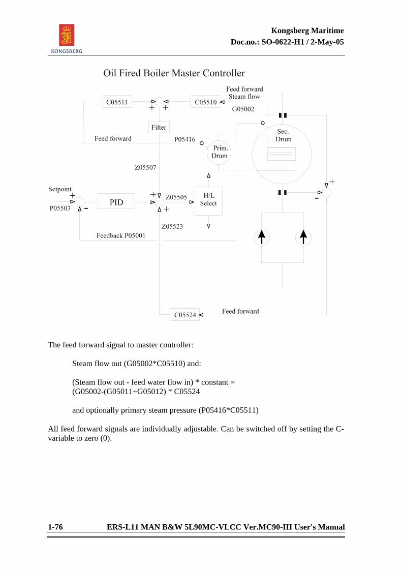
Kongsberg Maritime Doc.no.: SO-0622-H1 / 2-May-05
1-76 ERS-L11 MAN B&W 5L90MC-VLCC Ver.MC90-III User's Manual
The feed forward signal to master controller: Steam flow out (G05002*C05510) and: (Steam flow out - feed water flow in) * constant = (G05002-(G05011+G05012) * C05524 and optionally primary steam pressure (P05416*C05511) All feed forward signals are individually adjustable. Can be switched off by setting the C-variable to zero (0).
Kongsberg Maritime Doc.no.: SO-0622-H1 / 2-May-05
ERS-L11 MAN B&W 5L90MC-VLCC Ver.MC90-III User's Manual 1-77
<This page is intentionally left blank>
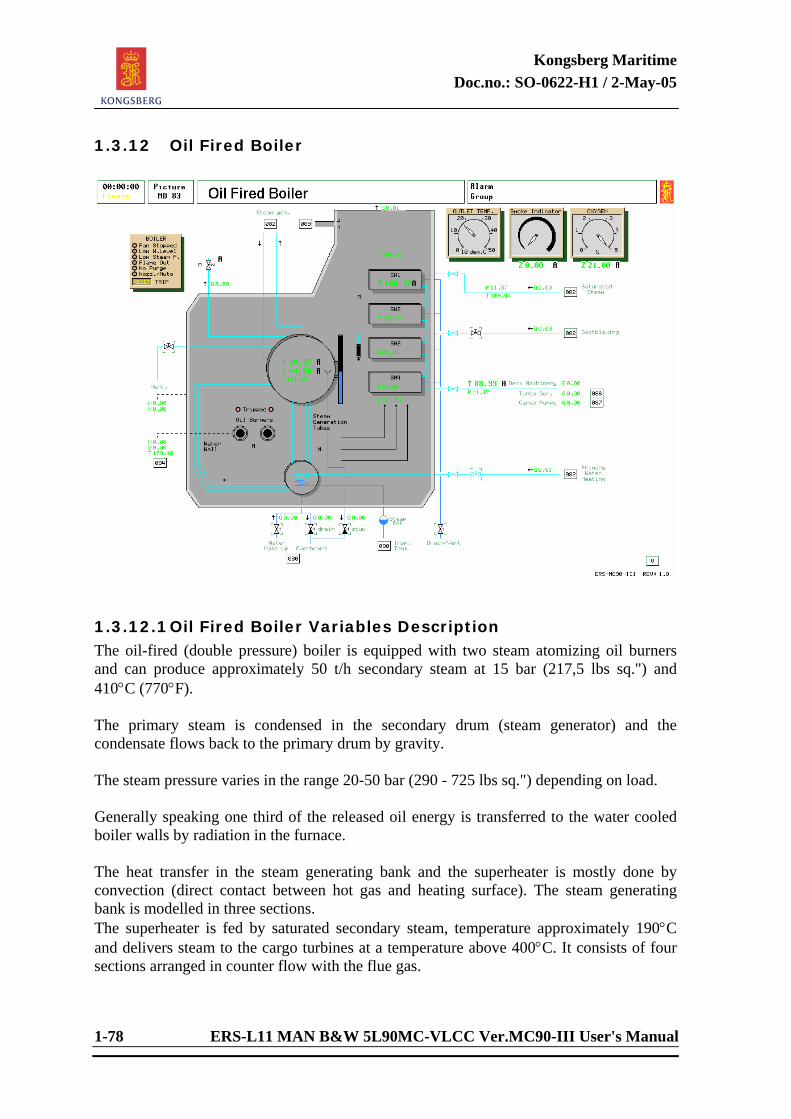
Kongsberg Maritime Doc.no.: SO-0622-H1 / 2-May-05
1-78 ERS-L11 MAN B&W 5L90MC-VLCC Ver.MC90-III User's Manual
1.3.12 Oil Fired Boiler
1.3.12.1 Oil Fired Boiler Variables Description The oil-fired (double pressure) boiler is equipped with two steam atomizing oil burners and can produce approximately 50 t/h secondary steam at 15 bar (217,5 lbs sq.") and 410°C (770°F). The primary steam is condensed in the secondary drum (steam generator) and the condensate flows back to the primary drum by gravity. The steam pressure varies in the range 20-50 bar (290 - 725 lbs sq.") depending on load. Generally speaking one third of the released oil energy is transferred to the water cooled boiler walls by radiation in the furnace. The heat transfer in the steam generating bank and the superheater is mostly done by convection (direct contact between hot gas and heating surface). The steam generating bank is modelled in three sections. The superheater is fed by saturated secondary steam, temperature approximately 190°C and delivers steam to the cargo turbines at a temperature above 400°C. It consists of four sections arranged in counter flow with the flue gas.
Kongsberg Maritime Doc.no.: SO-0622-H1 / 2-May-05
ERS-L11 MAN B&W 5L90MC-VLCC Ver.MC90-III User's Manual 1-79
The water transport within the boiler is based on natural circulation. The panel wall tubes and steam generating tubes are riser tubes. The down-comer tubes connecting the upper and lower drum are placed outside the boiler walls (not shown in the drawing). The boiler must be fired with correct oil/air ratio, and carefully so that the superheater is not damaged (serious steam leakage ). Highest safe metal temperature in the superheater is 480°C. Note that the superheater is cooled by its steam flow. When this is low, greater attention is required from the operator with respect to overheating. The boiler has an oxygen analyser and a smoke indicator. The combustion control system should be trimmed to give approximately 1% oxygen in flue gas (5% excess air). Combustion at more than 5% oxygen results in great flue gas energy losses and is very uneconomic. Less than 1% oxygen results in sooting tendencies with increasing smoke content in the flue gas. The system is furnished with soot blowing equipment to clean the heat transfer surfaces and increase the boiler efficiency. A steam heater supplied by secondary steam is installed in the lower primary water drum. The primary water can therefore be heated when the boiler is out of operation, to prepare for a short and safe firing up period.
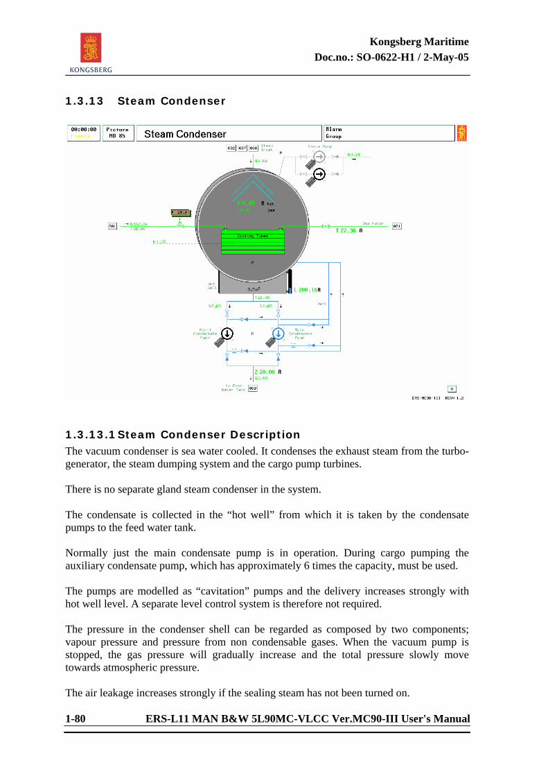
Kongsberg Maritime Doc.no.: SO-0622-H1 / 2-May-05
1-80 ERS-L11 MAN B&W 5L90MC-VLCC Ver.MC90-III User's Manual
1.3.13 Steam Condenser
1.3.13.1 Steam Condenser Description The vacuum condenser is sea water cooled. It condenses the exhaust steam from the turbo-generator, the steam dumping system and the cargo pump turbines. There is no separate gland steam condenser in the system. The condensate is collected in the “hot well” from which it is taken by the condensate pumps to the feed water tank. Normally just the main condensate pump is in operation. During cargo pumping the auxiliary condensate pump, which has approximately 6 times the capacity, must be used. The pumps are modelled as “cavitation” pumps and the delivery increases strongly with hot well level. A separate level control system is therefore not required. The pressure in the condenser shell can be regarded as composed by two components; vapour pressure and pressure from non condensable gases. When the vacuum pump is stopped, the gas pressure will gradually increase and the total pressure slowly move towards atmospheric pressure. The air leakage increases strongly if the sealing steam has not been turned on.
Kongsberg Maritime Doc.no.: SO-0622-H1 / 2-May-05
ERS-L11 MAN B&W 5L90MC-VLCC Ver.MC90-III User's Manual 1-81
The outlet valves of the cargo turbines should be closed when not in operation to stop air leakage from cargo turbine glands. The vapour pressure depends on the total steam flow to the condenser, the sea water flow and the sea water temperature. During cargo pumping a large amount of steam is required to be condensed and its heat of condensation transferred to the sea water cooling flow.
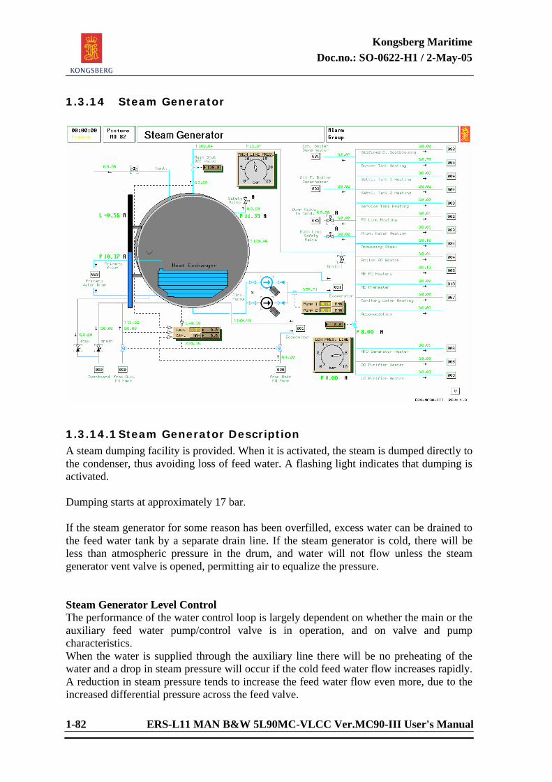
Kongsberg Maritime Doc.no.: SO-0622-H1 / 2-May-05
1-82 ERS-L11 MAN B&W 5L90MC-VLCC Ver.MC90-III User's Manual
1.3.14 Steam Generator
1.3.14.1 Steam Generator Description A steam dumping facility is provided. When it is activated, the steam is dumped directly to the condenser, thus avoiding loss of feed water. A flashing light indicates that dumping is activated. Dumping starts at approximately 17 bar. If the steam generator for some reason has been overfilled, excess water can be drained to the feed water tank by a separate drain line. If the steam generator is cold, there will be less than atmospheric pressure in the drum, and water will not flow unless the steam generator vent valve is opened, permitting air to equalize the pressure. Steam Generator Level Control The performance of the water control loop is largely dependent on whether the main or the auxiliary feed water pump/control valve is in operation, and on valve and pump characteristics. When the water is supplied through the auxiliary line there will be no preheating of the water and a drop in steam pressure will occur if the cold feed water flow increases rapidly. A reduction in steam pressure tends to increase the feed water flow even more, due to the increased differential pressure across the feed valve.
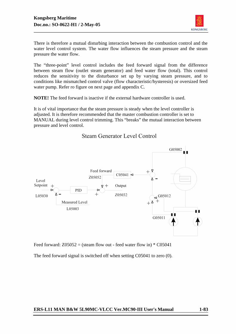
Kongsberg Maritime Doc.no.: SO-0622-H1 / 2-May-05
ERS-L11 MAN B&W 5L90MC-VLCC Ver.MC90-III User's Manual 1-83
There is therefore a mutual disturbing interaction between the combustion control and the water level control system. The water flow influences the steam pressure and the steam pressure the water flow. The “three-point” level control includes the feed forward signal from the difference between steam flow (outlet steam generator) and feed water flow (total). This control reduces the sensitivity to the disturbance set up by varying steam pressure, and to conditions like mismatched control valve (flow characteristic/hysteresis) or oversized feed water pump. Refer ro figure on next page and appendix C. NOTE! The feed forward is inactive if the external hardware controller is used. It is of vital importance that the steam pressure is steady when the level controller is adjusted. It is therefore recommended that the master combustion controller is set to MANUAL during level control trimming. This “breaks” the mutual interaction between pressure and level control.
Feed forward: Z05052 = (steam flow out - feed water flow in) * C05041 The feed forward signal is switched off when setting C05041 to zero (0).
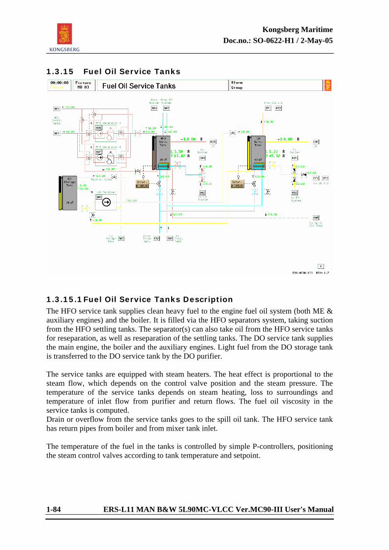
Kongsberg Maritime Doc.no.: SO-0622-H1 / 2-May-05
1-84 ERS-L11 MAN B&W 5L90MC-VLCC Ver.MC90-III User's Manual
1.3.15 Fuel Oil Service Tanks
1.3.15.1 Fuel Oil Service Tanks Description The HFO service tank supplies clean heavy fuel to the engine fuel oil system (both ME & auxiliary engines) and the boiler. It is filled via the HFO separators system, taking suction from the HFO settling tanks. The separator(s) can also take oil from the HFO service tanks for reseparation, as well as reseparation of the settling tanks. The DO service tank supplies the main engine, the boiler and the auxiliary engines. Light fuel from the DO storage tank is transferred to the DO service tank by the DO purifier. The service tanks are equipped with steam heaters. The heat effect is proportional to the steam flow, which depends on the control valve position and the steam pressure. The temperature of the service tanks depends on steam heating, loss to surroundings and temperature of inlet flow from purifier and return flows. The fuel oil viscosity in the service tanks is computed. Drain or overflow from the service tanks goes to the spill oil tank. The HFO service tank has return pipes from boiler and from mixer tank inlet. The temperature of the fuel in the tanks is controlled by simple P-controllers, positioning the steam control valves according to tank temperature and setpoint.
Kongsberg Maritime Doc.no.: SO-0622-H1 / 2-May-05
ERS-L11 MAN B&W 5L90MC-VLCC Ver.MC90-III User's Manual 1-85
<This page is intentionally left blank>
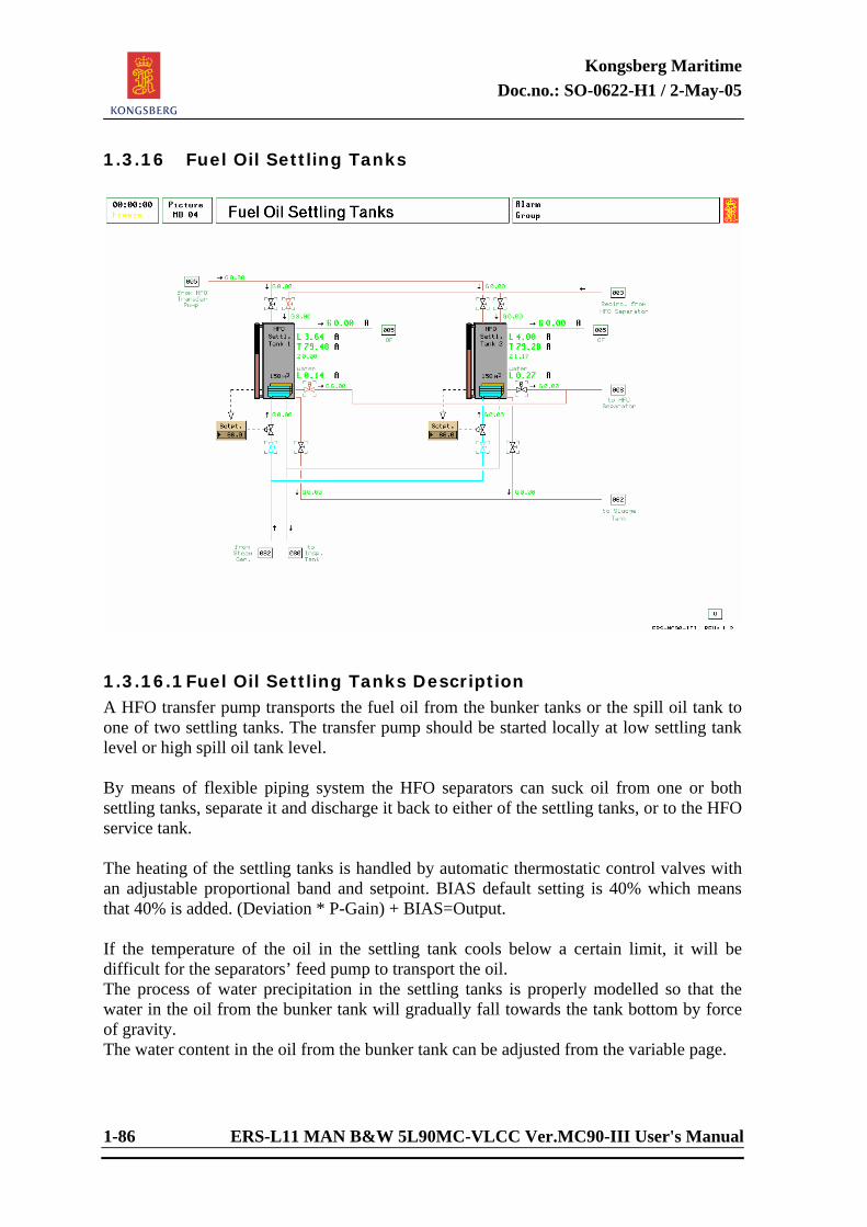
Kongsberg Maritime Doc.no.: SO-0622-H1 / 2-May-05
1-86 ERS-L11 MAN B&W 5L90MC-VLCC Ver.MC90-III User's Manual
1.3.16 Fuel Oil Settling Tanks
1.3.16.1 Fuel Oil Settling Tanks Description A HFO transfer pump transports the fuel oil from the bunker tanks or the spill oil tank to one of two settling tanks. The transfer pump should be started locally at low settling tank level or high spill oil tank level. By means of flexible piping system the HFO separators can suck oil from one or both settling tanks, separate it and discharge it back to either of the settling tanks, or to the HFO service tank. The heating of the settling tanks is handled by automatic thermostatic control valves with an adjustable proportional band and setpoint. BIAS default setting is 40% which means that 40% is added. (Deviation * P-Gain) + BIAS=Output. If the temperature of the oil in the settling tank cools below a certain limit, it will be difficult for the separators’ feed pump to transport the oil. The process of water precipitation in the settling tanks is properly modelled so that the water in the oil from the bunker tank will gradually fall towards the tank bottom by force of gravity. The water content in the oil from the bunker tank can be adjusted from the variable page.
Kongsberg Maritime Doc.no.: SO-0622-H1 / 2-May-05
ERS-L11 MAN B&W 5L90MC-VLCC Ver.MC90-III User's Manual 1-87
If the collected water is not discharged regularly, HFO separators’ problems will finally be experienced (such as a broken water seal). The drain valves can be opened at the local panel. In order to simulate visual inspection of the water/oil mixture, use is made of the valve's panel light. A steady light indicates that the valve is open and water is flowing. A flashing light indicates that the valve is open and mostly oil is flowing. Note that the flashing light function is available only when Local Panel is used for operating the fuel oil settling tanks, in the engine room. The fuel oil quality (heat value, viscosity and density) in the settling tanks is set manually by the instructor. Studies of how the fuel oil quality influences on the Main Engine (governor response) are recommended.
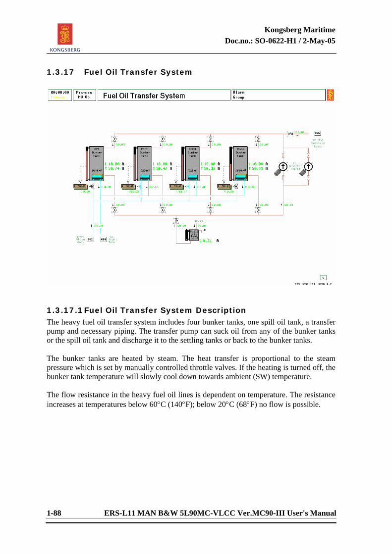
Kongsberg Maritime Doc.no.: SO-0622-H1 / 2-May-05
1-88 ERS-L11 MAN B&W 5L90MC-VLCC Ver.MC90-III User's Manual
1.3.17 Fuel Oil Transfer System
1.3.17.1 Fuel Oil Transfer System Description The heavy fuel oil transfer system includes four bunker tanks, one spill oil tank, a transfer pump and necessary piping. The transfer pump can suck oil from any of the bunker tanks or the spill oil tank and discharge it to the settling tanks or back to the bunker tanks. The bunker tanks are heated by steam. The heat transfer is proportional to the steam pressure which is set by manually controlled throttle valves. If the heating is turned off, the bunker tank temperature will slowly cool down towards ambient (SW) temperature. The flow resistance in the heavy fuel oil lines is dependent on temperature. The resistance increases at temperatures below 60°C (140°F); below 20°C (68°F) no flow is possible.
Kongsberg Maritime Doc.no.: SO-0622-H1 / 2-May-05
ERS-L11 MAN B&W 5L90MC-VLCC Ver.MC90-III User's Manual 1-89
The spill oil tank input comes from the following tanks: over flow: - HFO settling tank 1 - HFO settling tank 2 - HFO service tank - DO service tank drain flow: - Mixer tank - HFO service tank - DO service tank discharge flow: - Main Engine(s) lub.oil system Engine room fire If high alarm in the spill oil tank is disregarded and the tank starts to overflow, engine room fire is likely to (will) develop. The fire can be extinguished after the following actions have been taken: - the engine room ventilation fans stopped. - the main engine stopped. - the sea water fire line made operational.
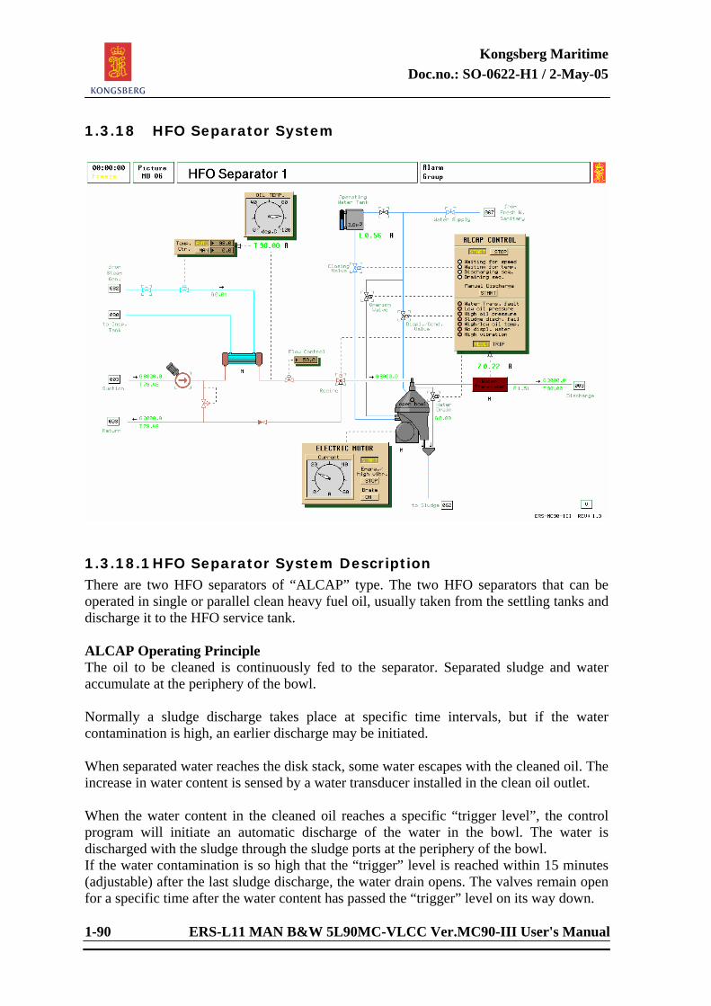
Kongsberg Maritime Doc.no.: SO-0622-H1 / 2-May-05
1-90 ERS-L11 MAN B&W 5L90MC-VLCC Ver.MC90-III User's Manual
1.3.18 HFO Separator System
1.3.18.1 HFO Separator System Description There are two HFO separators of “ALCAP” type. The two HFO separators that can be operated in single or parallel clean heavy fuel oil, usually taken from the settling tanks and discharge it to the HFO service tank. ALCAP Operating Principle The oil to be cleaned is continuously fed to the separator. Separated sludge and water accumulate at the periphery of the bowl. Normally a sludge discharge takes place at specific time intervals, but if the water contamination is high, an earlier discharge may be initiated. When separated water reaches the disk stack, some water escapes with the cleaned oil. The increase in water content is sensed by a water transducer installed in the clean oil outlet. When the water content in the cleaned oil reaches a specific “trigger level”, the control program will initiate an automatic discharge of the water in the bowl. The water is discharged with the sludge through the sludge ports at the periphery of the bowl. If the water contamination is so high that the “trigger” level is reached within 15 minutes (adjustable) after the last sludge discharge, the water drain opens. The valves remain open for a specific time after the water content has passed the “trigger” level on its way down.
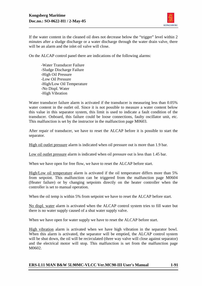
Kongsberg Maritime Doc.no.: SO-0622-H1 / 2-May-05
ERS-L11 MAN B&W 5L90MC-VLCC Ver.MC90-III User's Manual 1-91
If the water content in the cleaned oil does not decrease below the “trigger” level within 2 minutes after a sludge discharge or a water discharge through the water drain valve, there will be an alarm and the inlet oil valve will close. On the ALCAP control panel there are indications of the following alarms: -Water Transducer Failure -Sludge Discharge Failure -High Oil Pressure -Low Oil Pressure -High/Low Oil Temperature -No Displ. Water -High Vibration Water transducer failure alarm is activated if the transducer is measuring less than 0.05% water content in the outlet oil. Since it is not possible to measure a water content below this value in this separator system, this limit is used to indicate a fault condition of the transducer. Onboard, this failure could be loose connections, faulty oscillator unit, etc. This malfunction is set by the instructor in the malfunction page M0603. After repair of transducer, we have to reset the ALCAP before it is possible to start the separator. High oil outlet pressure alarm is indicated when oil pressure out is more than 1.9 bar. Low oil outlet pressure alarm is indicated when oil pressure out is less than 1.45 bar. When we have open for free flow, we have to reset the ALCAP before start. High/Low oil temperature alarm is activated if the oil temperature differs more than 5% from setpoint. This malfunction can be triggered from the malfunction page M0604 (Heater failure) or by changing setpoints directly on the heater controller when the controller is set to manual operation. When the oil temp is within 5% from setpoint we have to reset the ALCAP before start. No displ. water alarm is activated when the ALCAP control system tries to fill water but there is no water supply caused of a shut water supply valve. When we have open for water supply we have to reset the ALCAP before start. High vibration alarm is activated when we have high vibration in the separator bowl. When this alarm is activated, the separator will be emptied, the ALCAP control system will be shut down, the oil will be recirculated (three way valve will close against separator) and the electrical motor will stop. This malfunction is set from the malfunction page M0602.
Kongsberg Maritime Doc.no.: SO-0622-H1 / 2-May-05
1-92 ERS-L11 MAN B&W 5L90MC-VLCC Ver.MC90-III User's Manual
After repair attempt, we have to reset the ALCAP before start. Sludge discharge failure alarm is activated if the separator is not able to empty the separator for water and sludge. The ALCAP control system will directly try a new sludge/discharge sequence. If the water transducer still measures to high water content in the oil, the separator will be emptied, the ALCAP control system is shut down and the oil will be recirculated. This malfunction is set from the malfunction page M0601. After repair attempt, we have to reset the ALCAP before start.

Kongsberg Maritime Doc.no.: SO-0622-H1 / 2-May-05
ERS-L11 MAN B&W 5L90MC-VLCC Ver.MC90-III User's Manual 1-93
<This page is intentionally left blank>
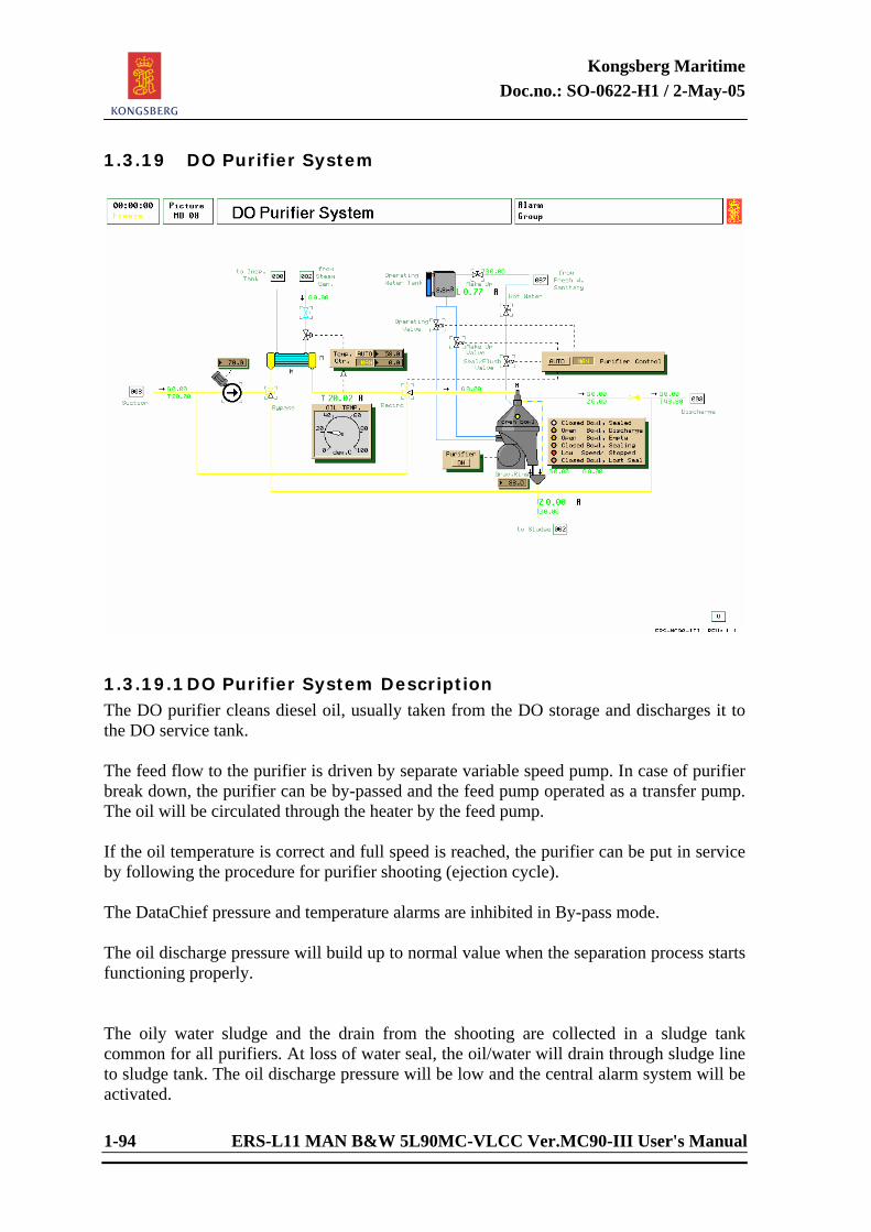
Kongsberg Maritime Doc.no.: SO-0622-H1 / 2-May-05
1-94 ERS-L11 MAN B&W 5L90MC-VLCC Ver.MC90-III User's Manual
1.3.19 DO Purifier System
1.3.19.1 DO Purifier System Description The DO purifier cleans diesel oil, usually taken from the DO storage and discharges it to the DO service tank. The feed flow to the purifier is driven by separate variable speed pump. In case of purifier break down, the purifier can be by-passed and the feed pump operated as a transfer pump. The oil will be circulated through the heater by the feed pump. If the oil temperature is correct and full speed is reached, the purifier can be put in service by following the procedure for purifier shooting (ejection cycle). The DataChief pressure and temperature alarms are inhibited in By-pass mode. The oil discharge pressure will build up to normal value when the separation process starts functioning properly. The oily water sludge and the drain from the shooting are collected in a sludge tank common for all purifiers. At loss of water seal, the oil/water will drain through sludge line to sludge tank. The oil discharge pressure will be low and the central alarm system will be activated.
Kongsberg Maritime Doc.no.: SO-0622-H1 / 2-May-05
ERS-L11 MAN B&W 5L90MC-VLCC Ver.MC90-III User's Manual 1-95
The purifier is modelled with an automatic dirt build-up within the bowl. After each ejection cycle the bowl is cleaned. If the dirt cumulative exceeds an upper limit, lost water seal will occur. The purifier therefore must be cleaned regularly. The rate of dirt build-up can be adjusted by the instructor. If the oil inlet temperature drops under a given limit or increases above a given limit, the normal separation process is disturbed, resulting in lost water seal. If the flow resistance of the discharge line is too high, the water seal will break. If the oil temperature reaches a critical low limit the purifier will stop due to motor overload. There is a constant consumption of operating water and the operating water tank must be manually refilled on low alarm or before. The efficiency of the purifier is much dependent on the gravity ring setting and the feed flow. Low feed flow and large gravity ring result in better purification while small gravity ring increases the maximum flow admitted before broken water seal is probable to occur. The cleaning procedure described will be done automatically at regular intervals by the PowerChief central monitoring system if the selector switch on the local purifier panel is in AUTO position.
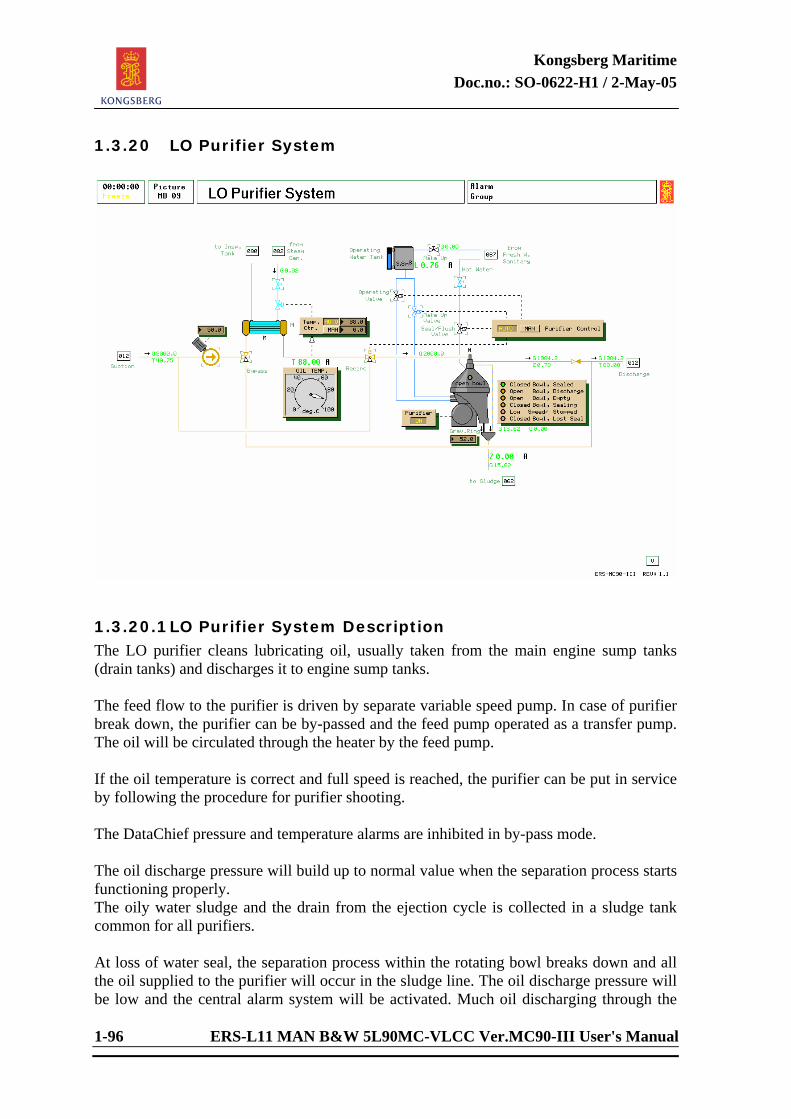
Kongsberg Maritime Doc.no.: SO-0622-H1 / 2-May-05
1-96 ERS-L11 MAN B&W 5L90MC-VLCC Ver.MC90-III User's Manual
1.3.20 LO Purifier System
1.3.20.1 LO Purifier System Description The LO purifier cleans lubricating oil, usually taken from the main engine sump tanks (drain tanks) and discharges it to engine sump tanks. The feed flow to the purifier is driven by separate variable speed pump. In case of purifier break down, the purifier can be by-passed and the feed pump operated as a transfer pump. The oil will be circulated through the heater by the feed pump. If the oil temperature is correct and full speed is reached, the purifier can be put in service by following the procedure for purifier shooting. The DataChief pressure and temperature alarms are inhibited in by-pass mode. The oil discharge pressure will build up to normal value when the separation process starts functioning properly. The oily water sludge and the drain from the ejection cycle is collected in a sludge tank common for all purifiers. At loss of water seal, the separation process within the rotating bowl breaks down and all the oil supplied to the purifier will occur in the sludge line. The oil discharge pressure will be low and the central alarm system will be activated. Much oil discharging through the
Kongsberg Maritime Doc.no.: SO-0622-H1 / 2-May-05
ERS-L11 MAN B&W 5L90MC-VLCC Ver.MC90-III User's Manual 1-97
sludge line (broken water seal) is indicated by flashing “oil inlet” light. The oil inlet valve should be closed immediately. The purifier is modelled with an automatic dirt build-up within the bowl. After each cleaning sequence the bowl is cleaned. If the dirt cumulative exceeds an upper limit, lost water seal will occur. The purifier must therefore be cleaned regularly. The rate of dirt build-up can be adjusted by the instructor. If the oil inlet temperature drops under a given limit or increases above a given limit, the normal separation process is disturbed, resulting in lost water seal. If the flow resistance of the discharge line is too high, the water seal will break. If the oil temperature reaches a critical low limit, the purifier will stop due to motor overload. There is a constant consumption of operating water, and the operating water tank must be manually refilled on low alarm or when needed. The efficiency of the purifier is much dependent on the gravity ring setting and the feed flow. Low feed flow and large gravity ring result in better purification while small gravity ring increases the maximum flow admitted before broken water seal is probable to occur. The cleaning procedure described will be done automatically at regular intervals by the PowerChief central monitoring system if the selector switch on the local purifier panel is in AUTO position.
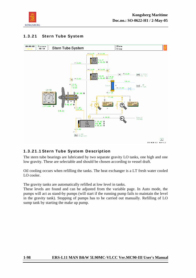
Kongsberg Maritime Doc.no.: SO-0622-H1 / 2-May-05
1-98 ERS-L11 MAN B&W 5L90MC-VLCC Ver.MC90-III User's Manual
1.3.21 Stern Tube System
1.3.21.1 Stern Tube System Description The stern tube bearings are lubricated by two separate gravity LO tanks, one high and one low gravity. These are selectable and should be chosen according to vessel draft. Oil cooling occurs when refilling the tanks. The heat exchanger is a LT fresh water cooled LO cooler. The gravity tanks are automatically refilled at low level in tanks. These levels are found and can be adjusted from the variable page. In Auto mode, the pumps will act as stand-by pumps (will start if the running pump fails to maintain the level in the gravity tank). Stopping of pumps has to be carried out manually. Refilling of LO sump tank by starting the make up pump.
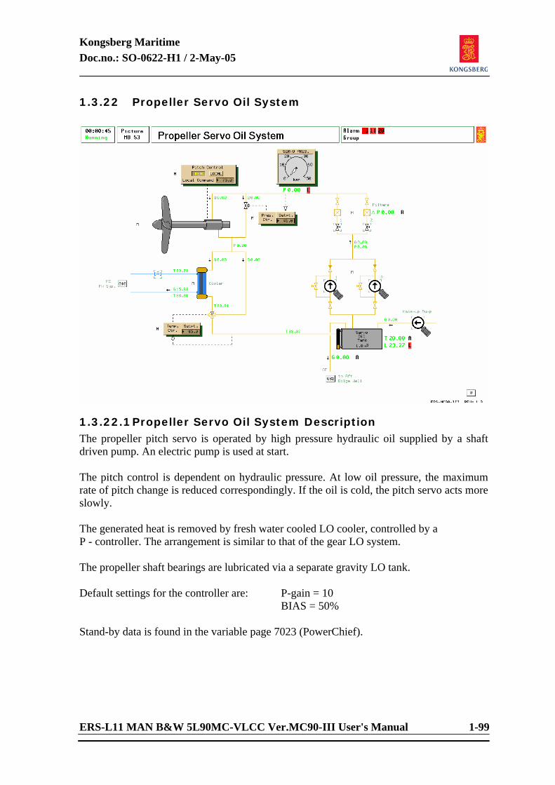
Kongsberg Maritime Doc.no.: SO-0622-H1 / 2-May-05
ERS-L11 MAN B&W 5L90MC-VLCC Ver.MC90-III User's Manual 1-99
1.3.22 Propeller Servo Oil System
1.3.22.1 Propeller Servo Oil System Description The propeller pitch servo is operated by high pressure hydraulic oil supplied by a shaft driven pump. An electric pump is used at start. The pitch control is dependent on hydraulic pressure. At low oil pressure, the maximum rate of pitch change is reduced correspondingly. If the oil is cold, the pitch servo acts more slowly. The generated heat is removed by fresh water cooled LO cooler, controlled by a P - controller. The arrangement is similar to that of the gear LO system. The propeller shaft bearings are lubricated via a separate gravity LO tank. Default settings for the controller are: P-gain = 10 BIAS = 50% Stand-by data is found in the variable page 7023 (PowerChief).
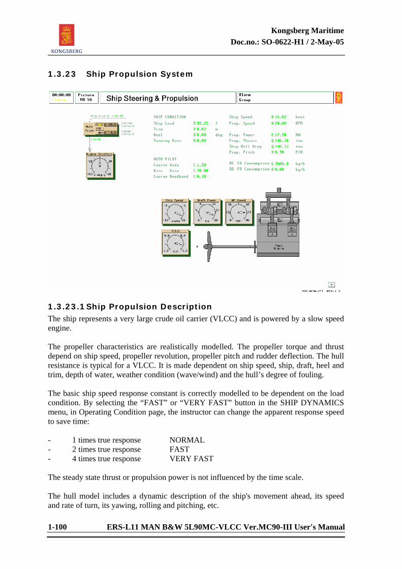
Kongsberg Maritime Doc.no.: SO-0622-H1 / 2-May-05
1-100 ERS-L11 MAN B&W 5L90MC-VLCC Ver.MC90-III User's Manual
1.3.23 Ship Propulsion System
1.3.23.1 Ship Propulsion Description The ship represents a very large crude oil carrier (VLCC) and is powered by a slow speed engine. The propeller characteristics are realistically modelled. The propeller torque and thrust depend on ship speed, propeller revolution, propeller pitch and rudder deflection. The hull resistance is typical for a VLCC. It is made dependent on ship speed, ship, draft, heel and trim, depth of water, weather condition (wave/wind) and the hull’s degree of fouling. The basic ship speed response constant is correctly modelled to be dependent on the load condition. By selecting the “FAST” or “VERY FAST” button in the SHIP DYNAMICS menu, in Operating Condition page, the instructor can change the apparent response speed to save time: - 1 times true response NORMAL - 2 times true response FAST - 4 times true response VERY FAST The steady state thrust or propulsion power is not influenced by the time scale. The hull model includes a dynamic description of the ship's movement ahead, its speed and rate of turn, its yawing, rolling and pitching, etc.
Kongsberg Maritime Doc.no.: SO-0622-H1 / 2-May-05
ERS-L11 MAN B&W 5L90MC-VLCC Ver.MC90-III User's Manual 1-101
The hull drag force includes water resistance due to waves, wind and ice. The weather condition sets the general level of wave disturbance. There is no directional influence. The wind force is specified by mean wind speed and wind direction. The influence of the sea waves, set by the instructor, is modelled in three ways: (1) The wave effect on the propeller is simulated by adding the hydrodynamic propeller torque random disturbances (low-pass filtered, white noise). The revolution will vary somewhat and the AutoChief system will be disturbed in its speed controlling function. (2) The pitch and roll movement of the ship is simulated by adding to the liquid level in the following tanks periodic random disturbances (band-pass filtered, white noise): - ME FW expansion tank - ME LO service tank - HFO service tank - DO service tank - engine room bilge well - steam generator water drum (3) The breaking effect of the waves on ship speed is simulated by increasing the propulsion resistance. Ship speed will drop and the main engines will thus be more heavily loaded. The water depth can be specified and the “shallow water” effect demonstrated. The effect is noticeable only if the depth is less than 2-3 times ship draft. A bow thruster can be operated from the bridge. The thruster pitch is adjustable. Note that the bow thruster force will decrease at increasing speed ahead and at full speed the bow thruster hardly has any effect. Electric power is taken from Main Bus Bar 2, normally supplied by the shaft generator.
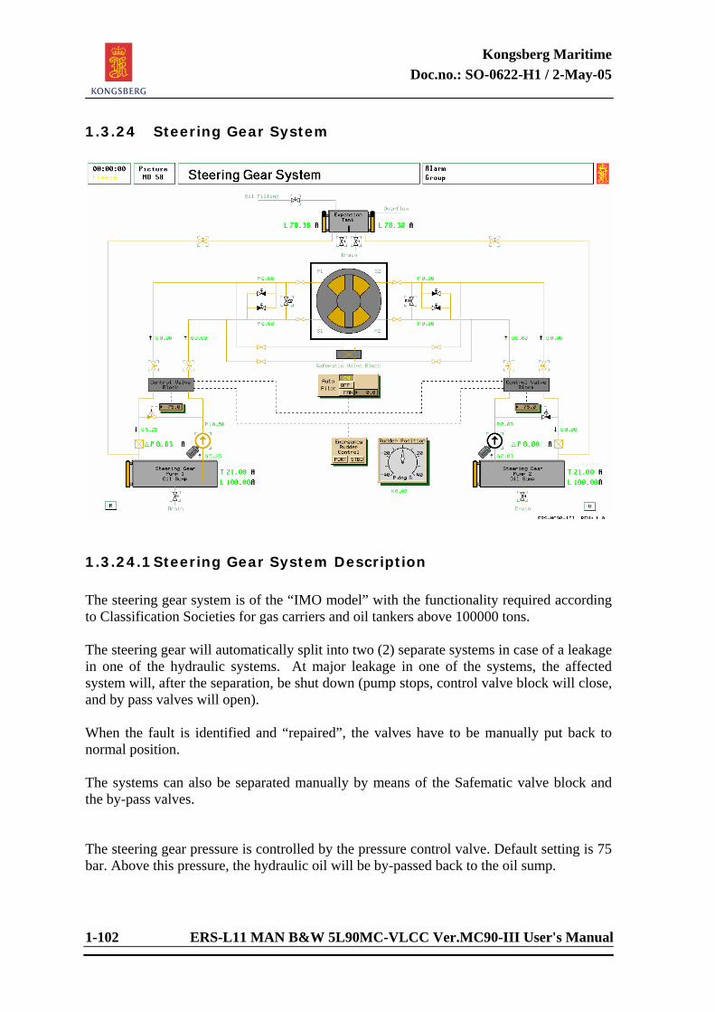
Kongsberg Maritime Doc.no.: SO-0622-H1 / 2-May-05
1-102 ERS-L11 MAN B&W 5L90MC-VLCC Ver.MC90-III User's Manual
1.3.24 Steering Gear System
1.3.24.1 Steering Gear System Description The steering gear system is of the “IMO model” with the functionality required according to Classification Societies for gas carriers and oil tankers above 100000 tons. The steering gear will automatically split into two (2) separate systems in case of a leakage in one of the hydraulic systems. At major leakage in one of the systems, the affected system will, after the separation, be shut down (pump stops, control valve block will close, and by pass valves will open). When the fault is identified and “repaired”, the valves have to be manually put back to normal position. The systems can also be separated manually by means of the Safematic valve block and the by-pass valves. The steering gear pressure is controlled by the pressure control valve. Default setting is 75 bar. Above this pressure, the hydraulic oil will be by-passed back to the oil sump.
Kongsberg Maritime Doc.no.: SO-0622-H1 / 2-May-05
ERS-L11 MAN B&W 5L90MC-VLCC Ver.MC90-III User's Manual 1-103
Emergency steering is carried out from this diagram, in case of system communication failure with the bridge. The steering gear is able to change the rudder position from 35 deg. to –30 within 48 sec. with one pump and 24 sec. with two pumps, undependant of ship speed (the increased demand of thrust on the rudder at higher ship speed is taken care of by increased pump pressure). For studies of mutual influence between the steering gear and autopilot the autopilot is made available in the mimic diagram 58.
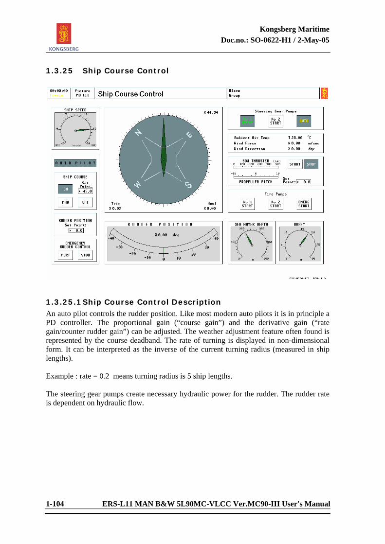
Kongsberg Maritime Doc.no.: SO-0622-H1 / 2-May-05
1-104 ERS-L11 MAN B&W 5L90MC-VLCC Ver.MC90-III User's Manual
1.3.25 Ship Course Control
1.3.25.1 Ship Course Control Description An auto pilot controls the rudder position. Like most modern auto pilots it is in principle a PD controller. The proportional gain (“course gain”) and the derivative gain (“rate gain/counter rudder gain”) can be adjusted. The weather adjustment feature often found is represented by the course deadband. The rate of turning is displayed in non-dimensional form. It can be interpreted as the inverse of the current turning radius (measured in ship lengths). Example : rate = 0.2 means turning radius is 5 ship lengths. The steering gear pumps create necessary hydraulic power for the rudder. The rudder rate is dependent on hydraulic flow.
Kongsberg Maritime Doc.no.: SO-0622-H1 / 2-May-05
ERS-L11 MAN B&W 5L90MC-VLCC Ver.MC90-III User's Manual 1-105
Ambient Temperatures The ambient sea water and air temperature can be set from the instructor’s Console. The sea water temperature affects the operational conditions of all FW, LO and air coolers. At high sea water temperature, problems may develop, especially if the heat exchangers are dirty. A modified sea water temperature is used as an “equilibrium” temperature to which the temperatures of different tanks, etc. gradually will drop if left without heating for a sufficient period of time. The air temperature in the machinery space is modelled, depending on total main engine and auxiliary engine power, ambient air temperature and number of engine room ventilation fans in operation. If an engine room fire occurs, the temperature will rapidly increase to very high levels. The machinery space air temperature affects the scavenging air temperature of all diesel engines and also affects the combustion temperature of the oil-fired boiler. A simple model of the engine control room (ECR) air conditioning system is included. If the air conditioner is not on or has failed, the engine control room temperature will gradually approach machinery space temperature. If an engine room fire occurs, the air conditioning system becomes overloaded and will fail. A simulated break down of the control monitor system (DataChief, AutoChief and PowerChief) occurs if the engine control room temperature exceeds the equipment's ultimate design temperature, 55°C. Note that the air conditioning system requires sea water for cooling. This is taken from the SW system. Lack of sea water is indicated by a flashing light.
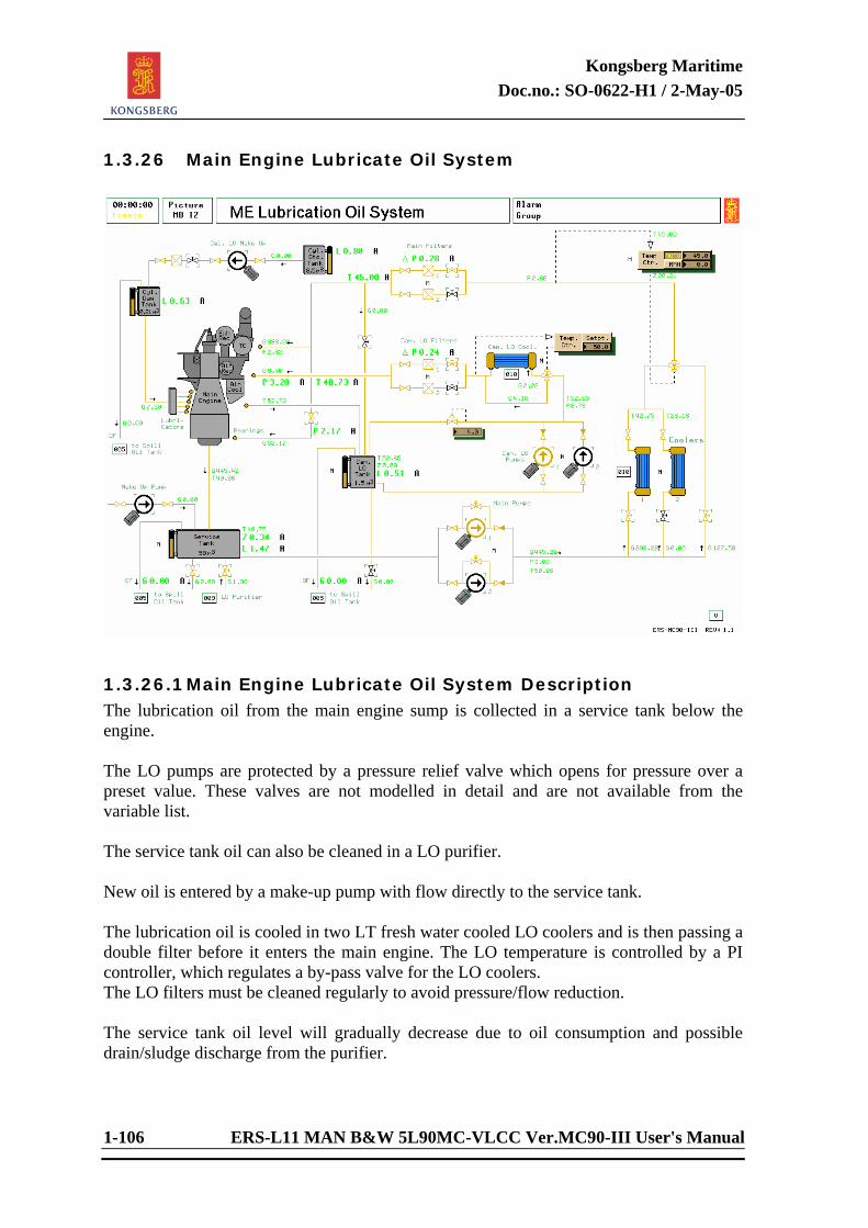
Kongsberg Maritime Doc.no.: SO-0622-H1 / 2-May-05
1-106 ERS-L11 MAN B&W 5L90MC-VLCC Ver.MC90-III User's Manual
1.3.26 Main Engine Lubricate Oil System
1.3.26.1 Main Engine Lubricate Oil System Description The lubrication oil from the main engine sump is collected in a service tank below the engine. The LO pumps are protected by a pressure relief valve which opens for pressure over a preset value. These valves are not modelled in detail and are not available from the variable list. The service tank oil can also be cleaned in a LO purifier. New oil is entered by a make-up pump with flow directly to the service tank. The lubrication oil is cooled in two LT fresh water cooled LO coolers and is then passing a double filter before it enters the main engine. The LO temperature is controlled by a PI controller, which regulates a by-pass valve for the LO coolers. The LO filters must be cleaned regularly to avoid pressure/flow reduction. The service tank oil level will gradually decrease due to oil consumption and possible drain/sludge discharge from the purifier.
Kongsberg Maritime Doc.no.: SO-0622-H1 / 2-May-05
ERS-L11 MAN B&W 5L90MC-VLCC Ver.MC90-III User's Manual 1-107
The level is unstable in poor weather and if the level is low, there may be false alarms/shut downs. If the purifier is operated with “broken” water seal, much oil is continuously discharged to the sludge tank and there is a risk of emptying the LO well completely. The oil pressure after the pumps will be reduced towards zero as the LO service well runs dry. The oil temperature in the service tank is affected by the return oil flow/temperature from the main engine, the oil flow/temperature from the purifier and the heat loss to the surroundings. If all inlet flows stop, the temperature will gradually approach ambient air temperature. Low oil temperature gives reduced pressure at main engine. Cylinder Lubrication A simple cylinder lubrication model is included. There will be a steady consumption of cylinder oil, dependent on main engine speed. The cylinder LO tank must be refilled periodically. At low cylinder LO tank level there will be ME slow down/shut down. Cam Lubrication The lubrication oil from the main engine cam shaft is collected in a cam shaft LO tank. The LO pressure is controlled after the two cam LO pumps by a pressure control valve with return flow to the cam LO tank. Cam LO tank make-up is taken from the LO inlet main engine line. Discharge of the tank is directly to the spill oil tank. The cam lubrication oil is cooled by a LT fresh water cooled LO cooler and is then passing a double filter before it enters the main engine. The LO temperature is controlled by a P controller, which regulates a by-pass valve for the cam LO cooler. The LO filters must be cleaned regularly to avoid pressure/flow reduction.
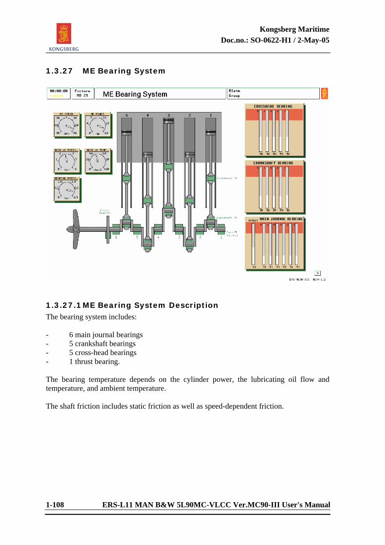
Kongsberg Maritime Doc.no.: SO-0622-H1 / 2-May-05
1-108 ERS-L11 MAN B&W 5L90MC-VLCC Ver.MC90-III User's Manual
1.3.27 ME Bearing System
1.3.27.1 ME Bearing System Description The bearing system includes: - 6 main journal bearings - 5 crankshaft bearings - 5 cross-head bearings - 1 thrust bearing. The bearing temperature depends on the cylinder power, the lubricating oil flow and temperature, and ambient temperature. The shaft friction includes static friction as well as speed-dependent friction.
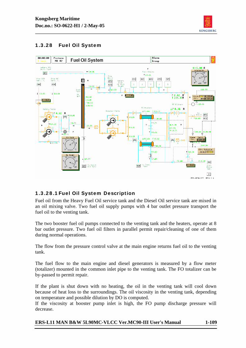
Kongsberg Maritime Doc.no.: SO-0622-H1 / 2-May-05
ERS-L11 MAN B&W 5L90MC-VLCC Ver.MC90-III User's Manual 1-109
1.3.28 Fuel Oil System
1.3.28.1 Fuel Oil System Description Fuel oil from the Heavy Fuel Oil service tank and the Diesel Oil service tank are mixed in an oil mixing valve. Two fuel oil supply pumps with 4 bar outlet pressure transport the fuel oil to the venting tank. The two booster fuel oil pumps connected to the venting tank and the heaters, operate at 8 bar outlet pressure. Two fuel oil filters in parallel permit repair/cleaning of one of them during normal operations. The flow from the pressure control valve at the main engine returns fuel oil to the venting tank. The fuel flow to the main engine and diesel generators is measured by a flow meter (totalizer) mounted in the common inlet pipe to the venting tank. The FO totalizer can be by-passed to permit repair. If the plant is shut down with no heating, the oil in the venting tank will cool down because of heat loss to the surroundings. The oil viscosity in the venting tank, depending on temperature and possible dilution by DO is computed. If the viscosity at booster pump inlet is high, the FO pump discharge pressure will decrease.
Kongsberg Maritime Doc.no.: SO-0622-H1 / 2-May-05
1-110 ERS-L11 MAN B&W 5L90MC-VLCC Ver.MC90-III User's Manual
The flow resistance in FO heaters and filters are dependent on viscosity. The FO pipe line and the venting tank can be heated by steam (steam tracing). The steam has to be turned on/off manually. If the oil in the FO pipe gets too cold, the pressure drop across the FO filter and FO heater increases strongly. The oil pressure from the booster pumps will drop correspondingly. The oil delivery from the booster pumps is reduced if the suction pressure drops below a certain limit. Because of the steam tracing facility, the main engine can be stopped and restarted on HFO. The normal procedure, however, is to change to DO a short time before shut down of engine. This has a cleaning effect by filling the piping system with diesel oil and ensures a safe start-up at a later time. The change over from HFO to DO or vice versa should be performed gradually. If the rate of temperature reduction during transfer from HFO to DO is too high, some of the HP injection plungers might stick due to plunger liner contraction / reduced lubrication. The heavy fuel oil tank and the venting tank can be drained to the spill oil tank. If a water leakage in the service tank heater has occurred, it will be necessary to empty the HFO tank and to drain water from the venting tank. Fuel Oil Gassing If the fuel oil temperature after the FO heaters rises higher than the fuel’s boiling temperature, “gassing” of the oil is simulated. Oil viscosity is taken as a “gassing indicator”. As this falls under approximately 2 cSt, gassing of the fuel oil gradually starts, leading to: - The running of the main engine is disturbed. - The signal from the viscosity meter becomes very noisy. Normally HFO gassing develops above 135°C and for DO above 80°C (adjustable). Fuel Oil Viscosity Control The viscosity controller positions the steam valve of the FO heater directly (single PID loop), or indirectly by adjusting the setpoint of a separate slave controller (cascade control). The slave controller is of PID type. The feed back signal to the slave controller is the mean tube metal temperature of the FO heaters (“high selected”).
Kongsberg Maritime Doc.no.: SO-0622-H1 / 2-May-05
ERS-L11 MAN B&W 5L90MC-VLCC Ver.MC90-III User's Manual 1-111
The viscosity sensor can be mounted any place between the FO heater and ME inlet by specification of nominal transport time delay. Note that the actual time delay will be adjusted according to FO flow. The delay will increase rapidly at low FO flow and may then cause oscillations. At low load it may prove necessary to stabilize the control by reducing the steam supply to the FO heaters.
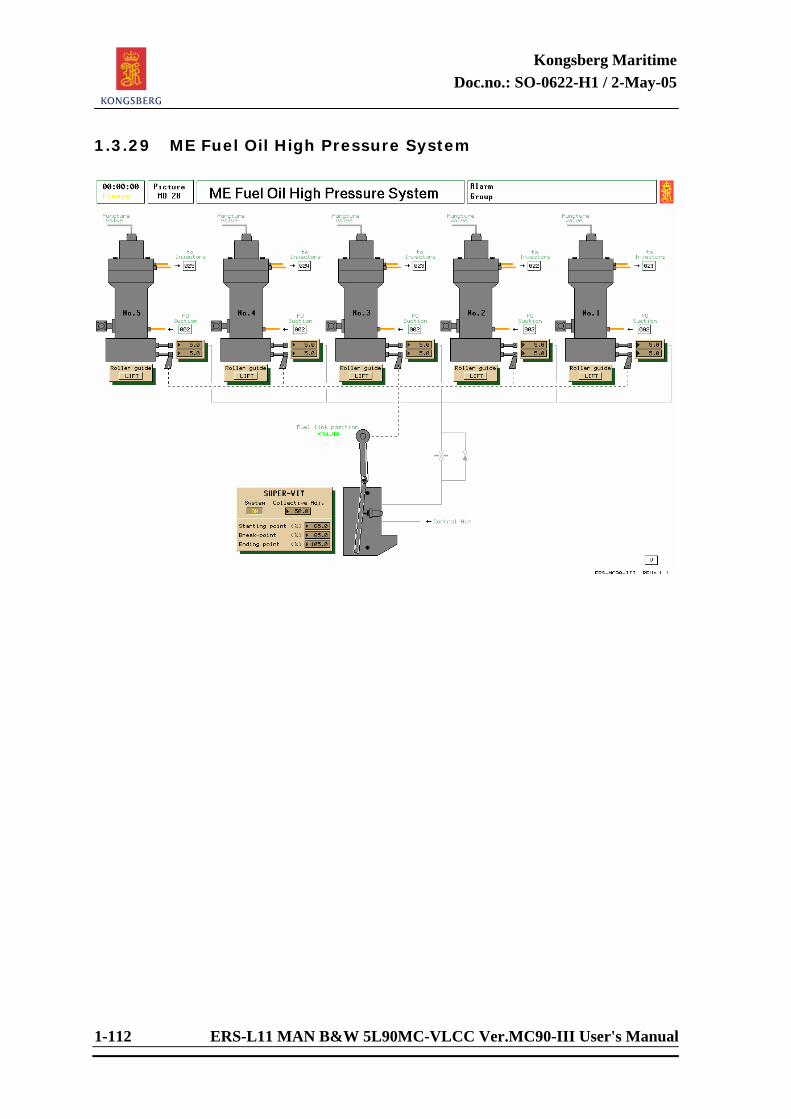
Kongsberg Maritime Doc.no.: SO-0622-H1 / 2-May-05
1-112 ERS-L11 MAN B&W 5L90MC-VLCC Ver.MC90-III User's Manual
1.3.29 ME Fuel Oil High Pressure System
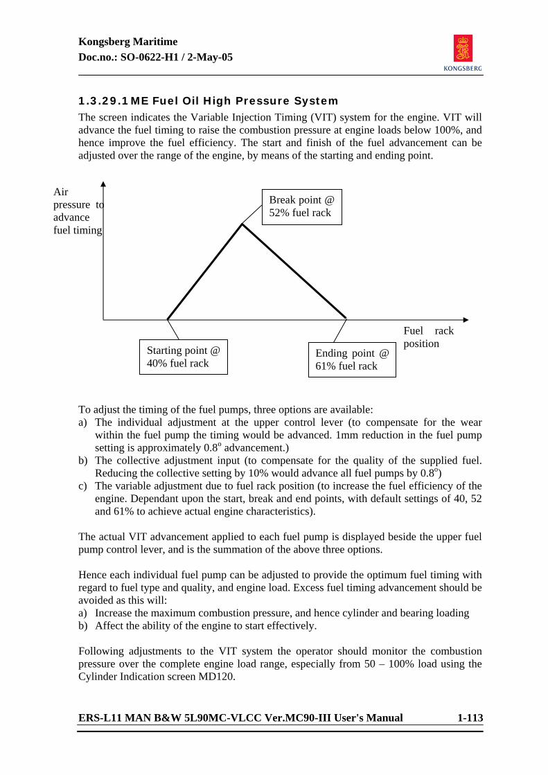
Kongsberg Maritime Doc.no.: SO-0622-H1 / 2-May-05
ERS-L11 MAN B&W 5L90MC-VLCC Ver.MC90-III User's Manual 1-113
1.3.29.1 ME Fuel Oil High Pressure System The screen indicates the Variable Injection Timing (VIT) system for the engine. VIT will advance the fuel timing to raise the combustion pressure at engine loads below 100%, and hence improve the fuel efficiency. The start and finish of the fuel advancement can be adjusted over the range of the engine, by means of the starting and ending point. To adjust the timing of the fuel pumps, three options are available: a) The individual adjustment at the upper control lever (to compensate for the wear
within the fuel pump the timing would be advanced. 1mm reduction in the fuel pump setting is approximately 0.8o advancement.)
b) The collective adjustment input (to compensate for the quality of the supplied fuel. Reducing the collective setting by 10% would advance all fuel pumps by 0.8o)
c) The variable adjustment due to fuel rack position (to increase the fuel efficiency of the engine. Dependant upon the start, break and end points, with default settings of 40, 52 and 61% to achieve actual engine characteristics).
The actual VIT advancement applied to each fuel pump is displayed beside the upper fuel pump control lever, and is the summation of the above three options. Hence each individual fuel pump can be adjusted to provide the optimum fuel timing with regard to fuel type and quality, and engine load. Excess fuel timing advancement should be avoided as this will: a) Increase the maximum combustion pressure, and hence cylinder and bearing loading b) Affect the ability of the engine to start effectively. Following adjustments to the VIT system the operator should monitor the combustion pressure over the complete engine load range, especially from 50 – 100% load using the Cylinder Indication screen MD120.
Starting point @ 40% fuel rack
Break point @ 52% fuel rack
Ending point @ 61% fuel rack
Air pressure to advance fuel timing
Fuel rack position
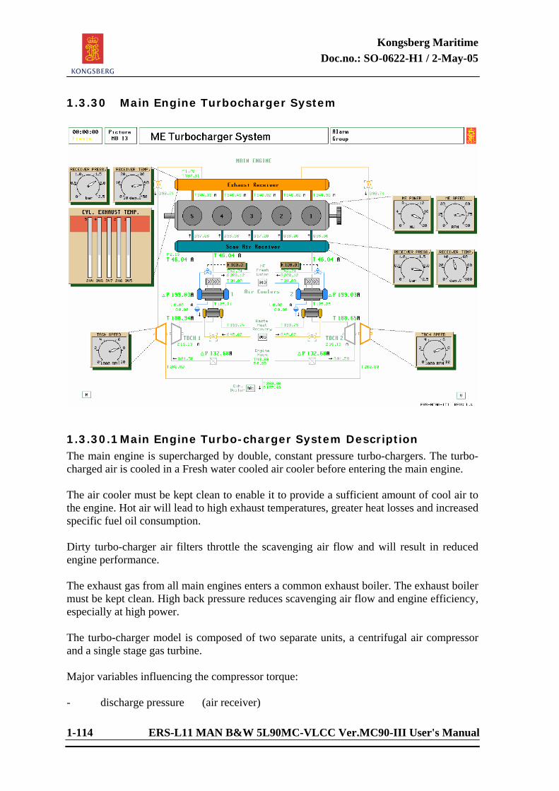
Kongsberg Maritime Doc.no.: SO-0622-H1 / 2-May-05
1-114 ERS-L11 MAN B&W 5L90MC-VLCC Ver.MC90-III User's Manual
1.3.30 Main Engine Turbocharger System
1.3.30.1 Main Engine Turbo-charger System Description The main engine is supercharged by double, constant pressure turbo-chargers. The turbo-charged air is cooled in a Fresh water cooled air cooler before entering the main engine. The air cooler must be kept clean to enable it to provide a sufficient amount of cool air to the engine. Hot air will lead to high exhaust temperatures, greater heat losses and increased specific fuel oil consumption. Dirty turbo-charger air filters throttle the scavenging air flow and will result in reduced engine performance. The exhaust gas from all main engines enters a common exhaust boiler. The exhaust boiler must be kept clean. High back pressure reduces scavenging air flow and engine efficiency, especially at high power. The turbo-charger model is composed of two separate units, a centrifugal air compressor and a single stage gas turbine. Major variables influencing the compressor torque: - discharge pressure (air receiver)
Kongsberg Maritime Doc.no.: SO-0622-H1 / 2-May-05
ERS-L11 MAN B&W 5L90MC-VLCC Ver.MC90-III User's Manual 1-115
- suction pressure (air filter diff. pressure) - air inlet temperature (density) - compressor speed Major turbine torque variables: - exhaust receiver pressure - exhaust receiver temperature - back pressure (exhaust boiler diff. pressure) - turbine speed The turbo-charger speed is computed on the basis of the torque balance differential equation shared by the turbine and the compressor model units. Preset value for start stop of aux. blower is respectively 0.2 bar and 0.4 bar. Slide valves can be changed to auto or manual from variable page 1301. Limits for
open/close of second slide valve is available from variable page 1301, preset values are low limit = 0.4 bar and high limit = 1.5 bar.
Waste Heat Recovery: See separate description.
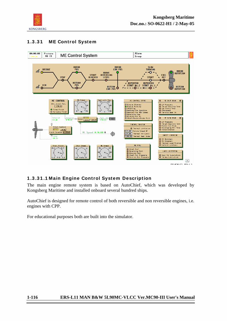
Kongsberg Maritime Doc.no.: SO-0622-H1 / 2-May-05
1-116 ERS-L11 MAN B&W 5L90MC-VLCC Ver.MC90-III User's Manual
1.3.31 ME Control System
1.3.31.1 Main Engine Control System Description The main engine remote system is based on AutoChief, which was developed by Kongsberg Maritime and installed onboard several hundred ships. AutoChief is designed for remote control of both reversible and non reversible engines, i.e. engines with CPP. For educational purposes both are built into the simulator.
Kongsberg Maritime Doc.no.: SO-0622-H1 / 2-May-05
ERS-L11 MAN B&W 5L90MC-VLCC Ver.MC90-III User's Manual 1-117
The ME Control System consists of the following: ME Control State Display
- The ME Control state display (upper part of AutoChief control panel) which shows
by lit diodes:
- The command position (bridge or engine control room)
- Stop, stop command is given, throttle is set to stop position
- Ahead if throttle is set to ahead position
- Astern if throttle is set to astern position
- Start blocked, if one or more of the following is activated:
Start failure: After 3 start attempts and the engine is still not running Start air pressure to low (default setting = 12 bar) Control air pressure to low (default setting = 2 bar) Reversing failure Start too long Braking failure Turning Gear engaged Engine tripped
- Above reversing level: When running ahead and astern command is given, the braking air is not supplied before the rpm is below the reversing level which is set to 33 rpm. When in Emergency Run, the reversing level is set to 40 rpm. If the engine is not stopped within the Brake Air Time Limit which is set to 8 seconds a Brake Air Failure alarm will be activated. This will probably happen if we at full speed ahead give an astern command because the ship speed/propeller effect will delay the rpm decreasing.
- Indication of cam position ahead/astern
- Indication of slow turning
- Indication of start attempts
- Indication of fuel off (the fuel pumps are punctured), when setting the throttle
to stop position.
- Indication of direction of propeller rotation.
Kongsberg Maritime Doc.no.: SO-0622-H1 / 2-May-05
1-118 ERS-L11 MAN B&W 5L90MC-VLCC Ver.MC90-III User's Manual
Additional Information and Adjustable Parameters AC CONTROL STATE “Pop-up” Window
- Indication of Engine running/stopped
- Indication of starting (start air is supplied)
- Waiting for ignition
- Waiting for reversing speed (waiting for the rpm to come below 33)
- Reversing cam (camshaft is changing position)
- Braking air on (rpm below 33 or 40 in emergency run)
- Indication of Start/Revers/Brake failure When popping up the AC CONTROL STATE window:
- The governor’s PID settings are available. These parameters are also available when popping up the governor directly. Changes of parameters at one place will automatically update the other.
- AC start air Off Speed (setting of rpm for start air cut off and fuel is supplied,
default = 33rpm for normal, 40 rpm for emergency) - Start air Time Limit (max. time for start air supply, default = 8 seconds). If the
engine is not started within 8 seconds, Start failure alarm is activated
- Brake Air Time Limit (max. time for braking air supply, default = 8 seconds. If the engine is not stopped within 8 seconds, Braking failure alarm is activated
- Critical speed Low and high limits (default = 40-42 rpm)
ME Shut Down Indication
- Indication of Low LO Pressure Shut Down
- Indication of High Temp. Thrust Bearing Shut Down
- Indication of High Temp. Cyl. Cooling Water Shut Down
- Indication of Overspeed Shut Down - Indication of Turning Gear In - When popping up the ME SHUT DOWN window, the settings for the
parameters are available.
Kongsberg Maritime Doc.no.: SO-0622-H1 / 2-May-05
ERS-L11 MAN B&W 5L90MC-VLCC Ver.MC90-III User's Manual 1-119
Thermal Monitor - Indication by lit diode when Thermal limiter is active.
- Indication of actual Speed Setpoint (speed command)
- Indication of Thermal rpm limit (will vary according to heat index)
- Indication of Thermal index (will vary according to load)
All settings for the thermal limiter are available when popping up the Thermal monitor window. Refer to description and figures in chapter 1.2.1.1.9. Load Monitor
- Indication, by lit diode, when Scav air limiter is active - Indication, by lit diode, when Torque limiter is active
- All settings for the scav. air and torque limiter are available when popping up
the window in MD19 picture. ME Slow Down
- Indication of ME Slow Downs, by lit diodes
- When popping up the window, all the different shut downs (10) with the different settings are available.
ME Fail
- Indication of Start failure
- Indication of Reversing failure
- Indication of Braking failure (engine not stopped within 8 sec.)
- Indication of Start air pressure (to low)
- Indication of Control Air pressure (to low) - The settings for minimum start air and control air pressure are available when
popping up the window.
Kongsberg Maritime Doc.no.: SO-0622-H1 / 2-May-05
1-120 ERS-L11 MAN B&W 5L90MC-VLCC Ver.MC90-III User's Manual
Safety Overrides If override of safety function(s) has been carried out from ECR or Bridge, this will be indicated on the ME Control System by lit diode(s):
- ME Shut Down (override of thrust bearing temperature and cyl. cool. water) - ME Slow Down (all slow downs are overrided) - Thermal Load Program (overrides the load program) - Control Limiters (overrides the ME Fail start inhibiters and load limiters)
Note taht the above slow down and shut down overrides van be changed in the “safety override” pop-up. Refer to 1.3.1.1.20 for details. All settings are available both from the pop-up windows and the variable pages. Fixed Propeller The propeller pitch is fixed to 0.9 P/D and the RPM is controlled from the dial on the AutoChief panel. Engine Speed Control The RPM set-point has different modes. These modes can be selected on the AutoChief panel, and are based on: - Shaft generator the RPM is set fixed to 60 Hz on the shaft generator (not present for the PTI/PTO
system) - Locked Fuel Link the fuel link is locked to avoid movement caused by the RPM governor - Direct Fuel Link controls the fuel link directly from the throttle Emergency Stop The fuel oil pumps are forced to “Stop” position.
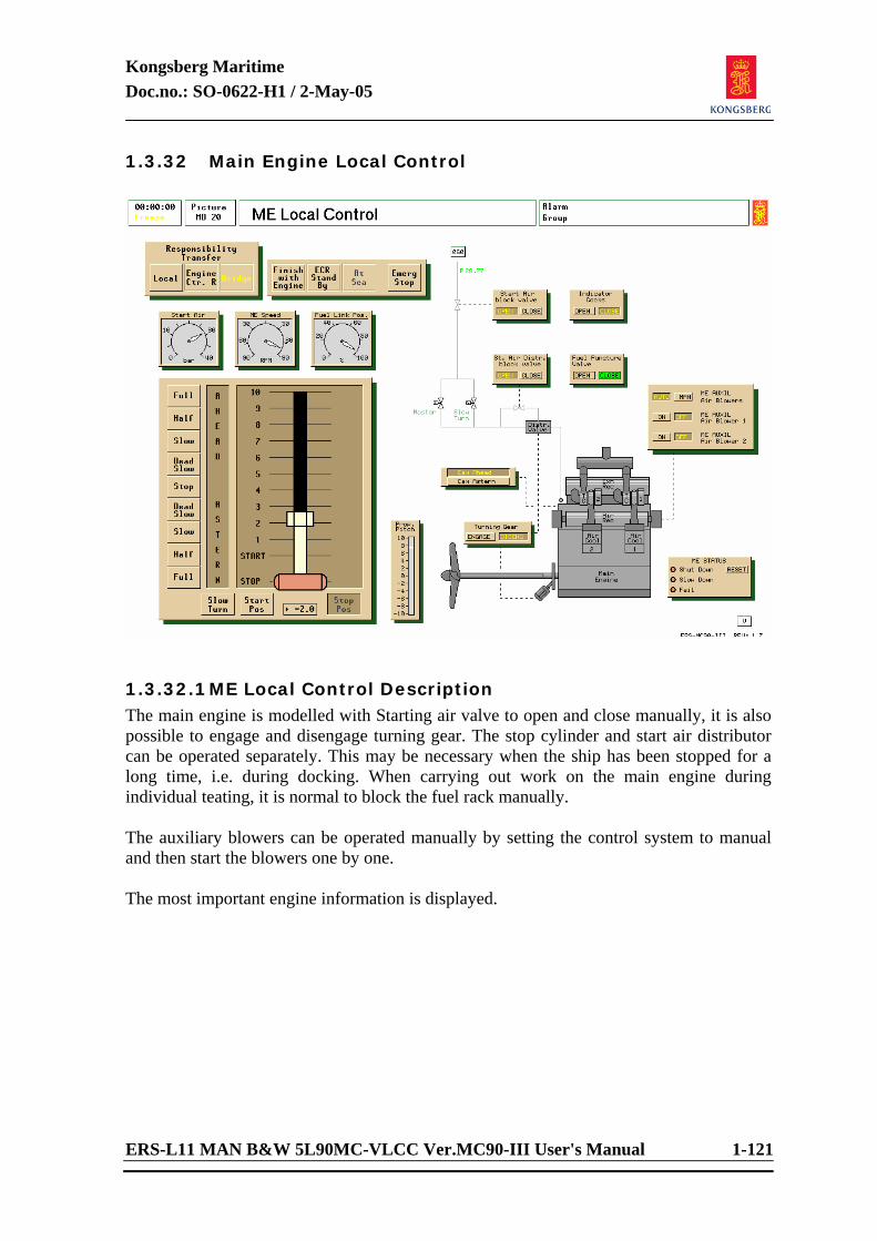
Kongsberg Maritime Doc.no.: SO-0622-H1 / 2-May-05
ERS-L11 MAN B&W 5L90MC-VLCC Ver.MC90-III User's Manual 1-121
1.3.32 Main Engine Local Control
1.3.32.1 ME Local Control Description The main engine is modelled with Starting air valve to open and close manually, it is also possible to engage and disengage turning gear. The stop cylinder and start air distributor can be operated separately. This may be necessary when the ship has been stopped for a long time, i.e. during docking. When carrying out work on the main engine during individual teating, it is normal to block the fuel rack manually. The auxiliary blowers can be operated manually by setting the control system to manual and then start the blowers one by one. The most important engine information is displayed.
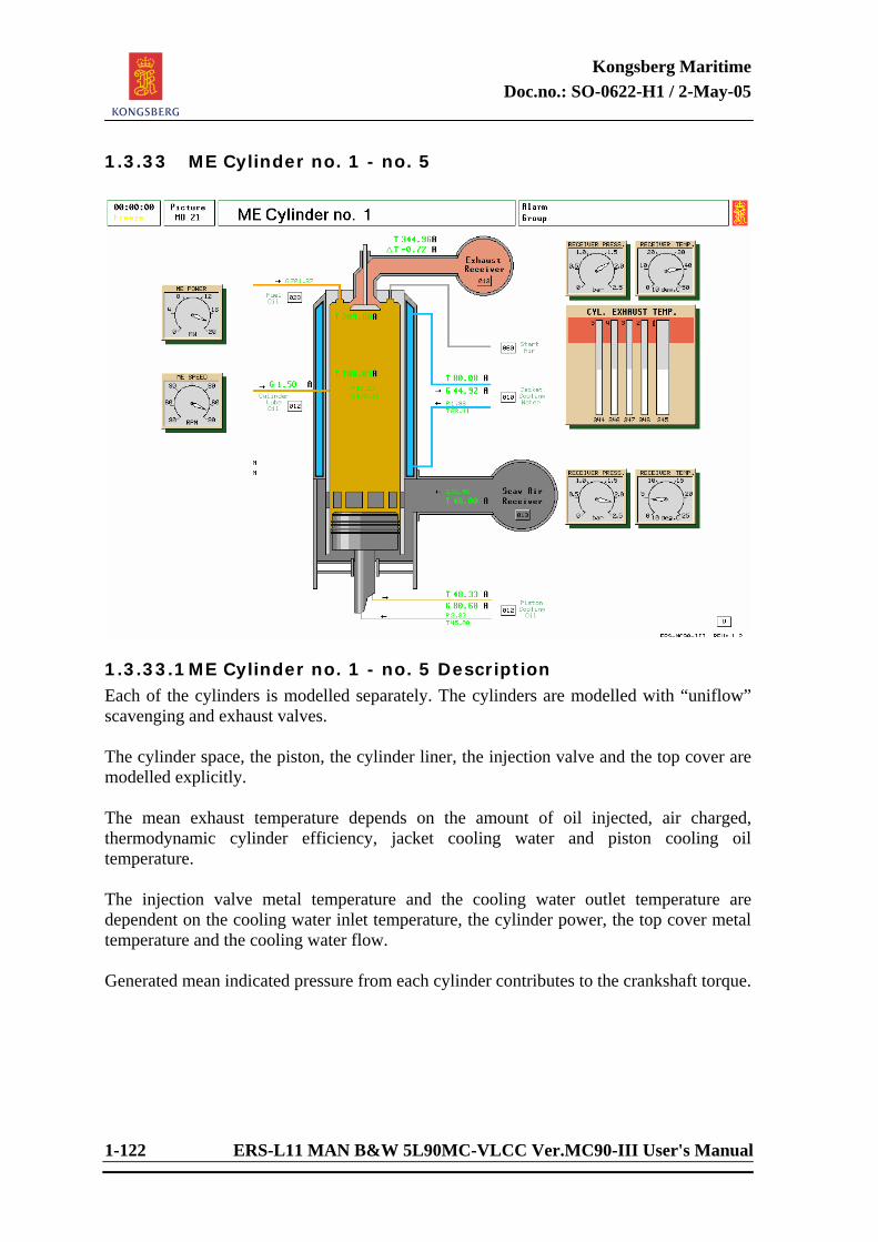
Kongsberg Maritime Doc.no.: SO-0622-H1 / 2-May-05
1-122 ERS-L11 MAN B&W 5L90MC-VLCC Ver.MC90-III User's Manual
1.3.33 ME Cylinder no. 1 - no. 5
1.3.33.1 ME Cylinder no. 1 - no. 5 Description Each of the cylinders is modelled separately. The cylinders are modelled with “uniflow” scavenging and exhaust valves. The cylinder space, the piston, the cylinder liner, the injection valve and the top cover are modelled explicitly. The mean exhaust temperature depends on the amount of oil injected, air charged, thermodynamic cylinder efficiency, jacket cooling water and piston cooling oil temperature. The injection valve metal temperature and the cooling water outlet temperature are dependent on the cooling water inlet temperature, the cylinder power, the top cover metal temperature and the cooling water flow. Generated mean indicated pressure from each cylinder contributes to the crankshaft torque.
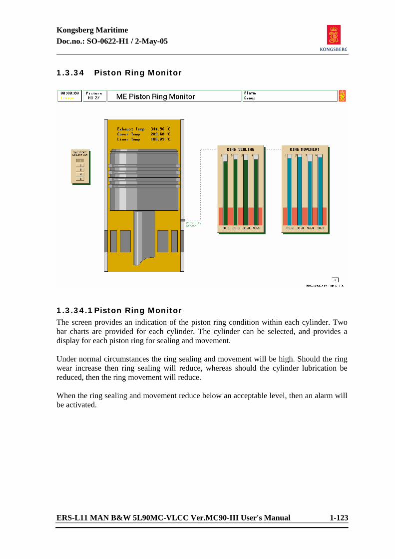
Kongsberg Maritime Doc.no.: SO-0622-H1 / 2-May-05
ERS-L11 MAN B&W 5L90MC-VLCC Ver.MC90-III User's Manual 1-123
1.3.34 Piston Ring Monitor
1.3.34.1 Piston Ring Monitor The screen provides an indication of the piston ring condition within each cylinder. Two bar charts are provided for each cylinder. The cylinder can be selected, and provides a display for each piston ring for sealing and movement. Under normal circumstances the ring sealing and movement will be high. Should the ring wear increase then ring sealing will reduce, whereas should the cylinder lubrication be reduced, then the ring movement will reduce. When the ring sealing and movement reduce below an acceptable level, then an alarm will be activated.
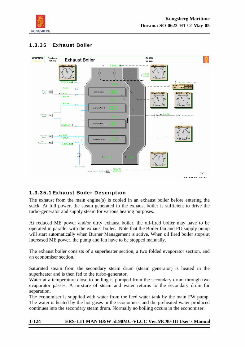
Kongsberg Maritime Doc.no.: SO-0622-H1 / 2-May-05
1-124 ERS-L11 MAN B&W 5L90MC-VLCC Ver.MC90-III User's Manual
1.3.35 Exhaust Boiler
1.3.35.1 Exhaust Boiler Description The exhaust from the main engine(s) is cooled in an exhaust boiler before entering the stack. At full power, the steam generated in the exhaust boiler is sufficient to drive the turbo-generator and supply steam for various heating purposes. At reduced ME power and/or dirty exhaust boiler, the oil-fired boiler may have to be operated in parallel with the exhaust boiler. Note that the Boiler fan and FO supply pump will start automatically when Burner Management is active. When oil fired boiler stops at increased ME power, the pump and fan have to be stopped manually. The exhaust boiler consists of a superheater section, a two folded evaporator section, and an economiser section. Saturated steam from the secondary steam drum (steam generator) is heated in the superheater and is then fed to the turbo-generator. Water at a temperature close to boiling is pumped from the secondary drum through two evaporator passes. A mixture of steam and water returns to the secondary drum for separation. The economiser is supplied with water from the feed water tank by the main FW pump. The water is heated by the hot gases in the economiser and the preheated water produced continues into the secondary steam drum. Normally no boiling occurs in the economiser.
Kongsberg Maritime Doc.no.: SO-0622-H1 / 2-May-05
ERS-L11 MAN B&W 5L90MC-VLCC Ver.MC90-III User's Manual 1-125
The exhaust flow passing the heating surfaces is dependent on the total exhaust flow and the exhaust damper position which is controlled by a PID controller. Transferred heat at each section depends on the local gas temperature and flow. The heat transfer in the evaporator is sharply reduced if the recirculation pump stops; this reduction causes a gradual drop in steam pressure. The exhaust boiler should be cleaned regularly, by using the air driven sootblowing equipment, if full turbo-generator power capability is to be maintained. Exhaust Boiler Damper Control When the exhaust boiler is in operation, the secondary steam pressure is kept constant by a PID controller which sets the position of the boiler’s gas dampers. When the steam load is low, more exhaust gas is by-passed and vice versa. When both boilers are in operation, there will be an indeterminate load sharing and possible oscillations if the pressure setpoints of the master controller and the damper controller are set equally. Realistically, large backlash in the damper positioning gear can easily be simulated by adjustment of the hysteresis element.
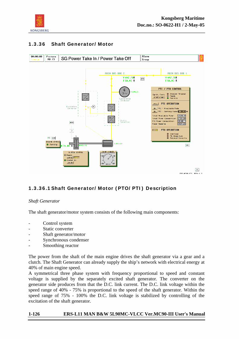
Kongsberg Maritime Doc.no.: SO-0622-H1 / 2-May-05
1-126 ERS-L11 MAN B&W 5L90MC-VLCC Ver.MC90-III User's Manual
1.3.36 Shaft Generator/Motor
1.3.36.1 Shaft Generator/Motor (PTO/PTI) Description Shaft Generator The shaft generator/motor system consists of the following main components: - Control system - Static converter - Shaft generator/motor - Synchronous condenser - Smoothing reactor The power from the shaft of the main engine drives the shaft generator via a gear and a clutch. The Shaft Generator can already supply the ship’s network with electrical energy at 40% of main engine speed. A symmetrical three phase system with frequency proportional to speed and constant voltage is supplied by the separately excited shaft generator. The converter on the generator side produces from that the D.C. link current. The D.C. link voltage within the speed range of 40% - 75% is proportional to the speed of the shaft generator. Within the speed range of 75% - 100% the D.C. link voltage is stabilized by controlling of the excitation of the shaft generator.
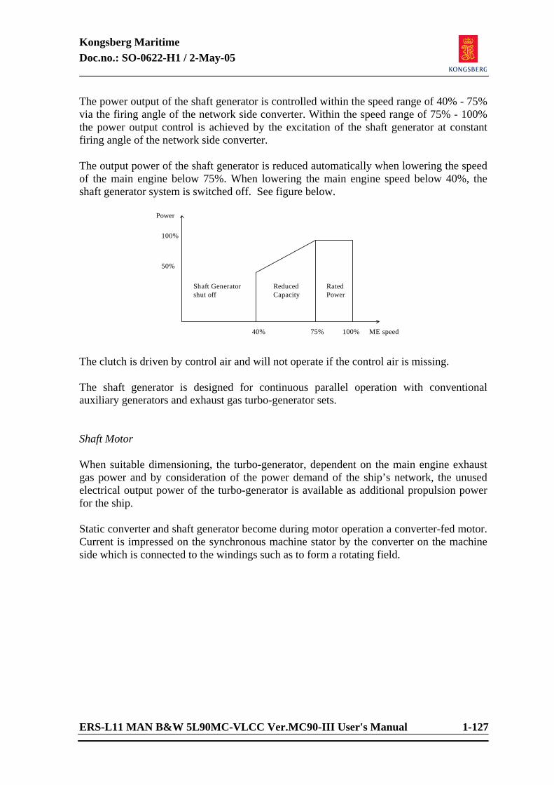
Kongsberg Maritime Doc.no.: SO-0622-H1 / 2-May-05
ERS-L11 MAN B&W 5L90MC-VLCC Ver.MC90-III User's Manual 1-127
The power output of the shaft generator is controlled within the speed range of 40% - 75% via the firing angle of the network side converter. Within the speed range of 75% - 100% the power output control is achieved by the excitation of the shaft generator at constant firing angle of the network side converter. The output power of the shaft generator is reduced automatically when lowering the speed of the main engine below 75%. When lowering the main engine speed below 40%, the shaft generator system is switched off. See figure below.
40% 75% 100%
50%
100%
ReducedCapacity
RatedPower
ME speed
Power
Shaft Generatorshut off
The clutch is driven by control air and will not operate if the control air is missing. The shaft generator is designed for continuous parallel operation with conventional auxiliary generators and exhaust gas turbo-generator sets. Shaft Motor When suitable dimensioning, the turbo-generator, dependent on the main engine exhaust gas power and by consideration of the power demand of the ship’s network, the unused electrical output power of the turbo-generator is available as additional propulsion power for the ship. Static converter and shaft generator become during motor operation a converter-fed motor. Current is impressed on the synchronous machine stator by the converter on the machine side which is connected to the windings such as to form a rotating field.
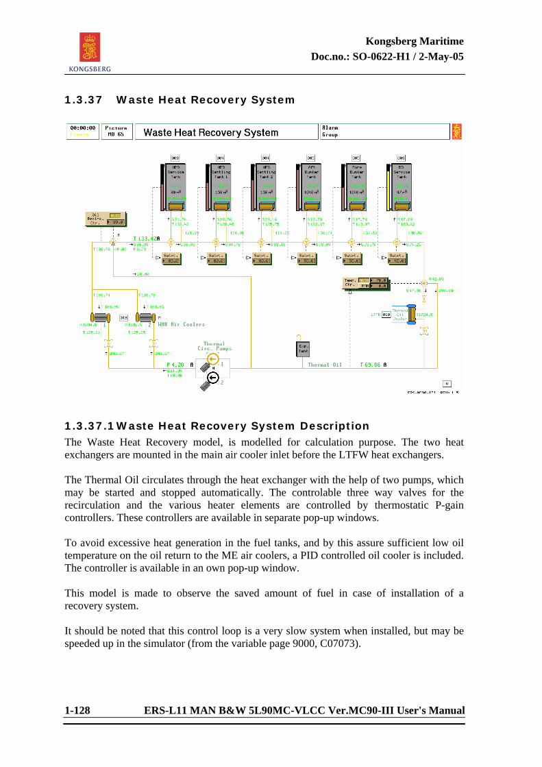
Kongsberg Maritime Doc.no.: SO-0622-H1 / 2-May-05
1-128 ERS-L11 MAN B&W 5L90MC-VLCC Ver.MC90-III User's Manual
1.3.37 Waste Heat Recovery System
1.3.37.1 Waste Heat Recovery System Description The Waste Heat Recovery model, is modelled for calculation purpose. The two heat exchangers are mounted in the main air cooler inlet before the LTFW heat exchangers. The Thermal Oil circulates through the heat exchanger with the help of two pumps, which may be started and stopped automatically. The controlable three way valves for the recirculation and the various heater elements are controlled by thermostatic P-gain controllers. These controllers are available in separate pop-up windows. To avoid excessive heat generation in the fuel tanks, and by this assure sufficient low oil temperature on the oil return to the ME air coolers, a PID controlled oil cooler is included. The controller is available in an own pop-up window. This model is made to observe the saved amount of fuel in case of installation of a recovery system. It should be noted that this control loop is a very slow system when installed, but may be speeded up in the simulator (from the variable page 9000, C07073).
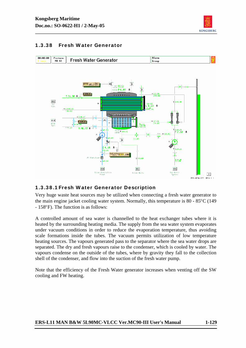
Kongsberg Maritime Doc.no.: SO-0622-H1 / 2-May-05
ERS-L11 MAN B&W 5L90MC-VLCC Ver.MC90-III User's Manual 1-129
1.3.38 Fresh Water Generator
1.3.38.1 Fresh Water Generator Description Very huge waste heat sources may be utilized when connecting a fresh water generator to the main engine jacket cooling water system. Normally, this temperature is 80 - 85°C (149 - 158°F). The function is as follows: A controlled amount of sea water is channelled to the heat exchanger tubes where it is heated by the surrounding heating media. The supply from the sea water system evaporates under vacuum conditions in order to reduce the evaporation temperature, thus avoiding scale formations inside the tubes. The vacuum permits utilization of low temperature heating sources. The vapours generated pass to the separator where the sea water drops are separated. The dry and fresh vapours raise to the condenser, which is cooled by water. The vapours condense on the outside of the tubes, where by gravity they fall to the collection shell of the condenser, and flow into the suction of the fresh water pump. Note that the efficiency of the Fresh Water generator increases when venting off the SW cooling and FW heating.
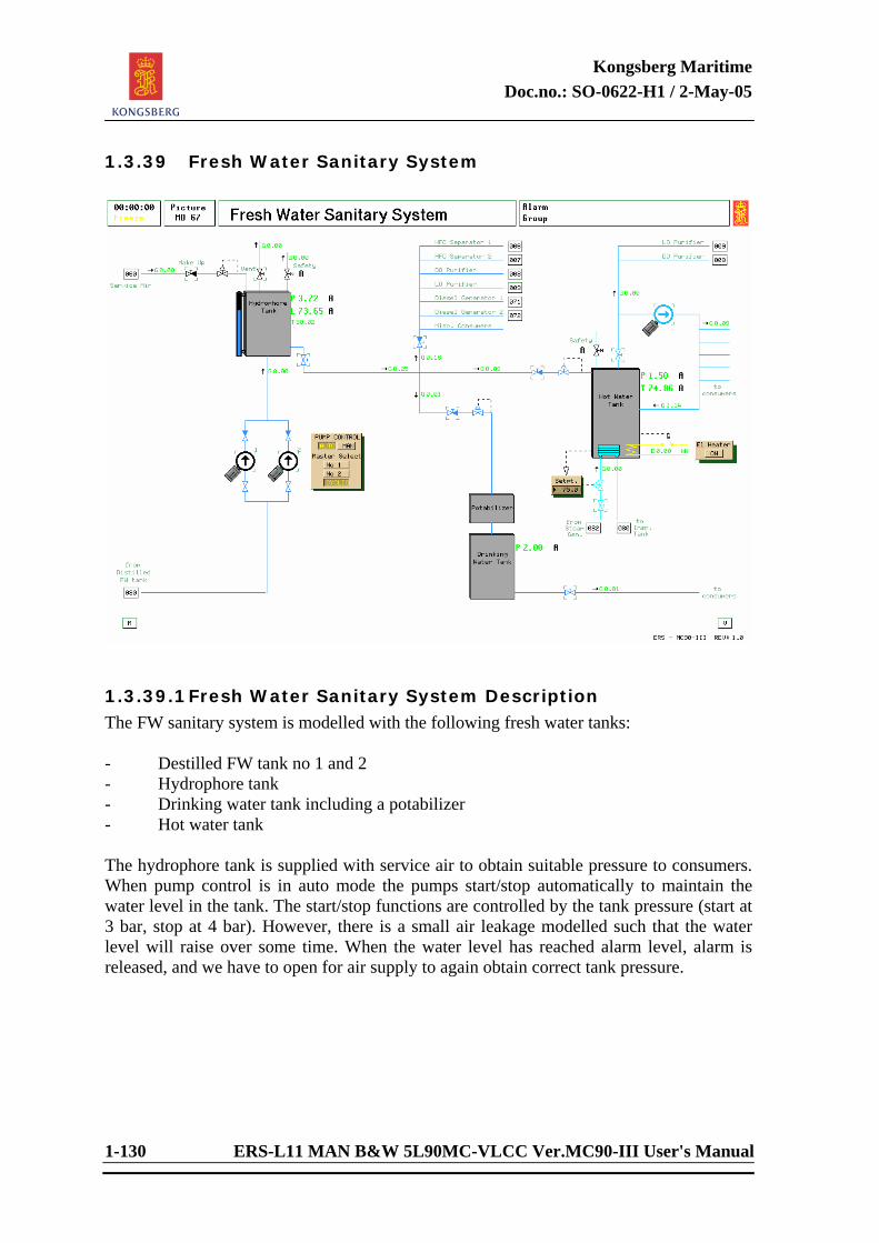
Kongsberg Maritime Doc.no.: SO-0622-H1 / 2-May-05
1-130 ERS-L11 MAN B&W 5L90MC-VLCC Ver.MC90-III User's Manual
1.3.39 Fresh Water Sanitary System
1.3.39.1 Fresh Water Sanitary System Description The FW sanitary system is modelled with the following fresh water tanks: - Destilled FW tank no 1 and 2 - Hydrophore tank - Drinking water tank including a potabilizer - Hot water tank The hydrophore tank is supplied with service air to obtain suitable pressure to consumers. When pump control is in auto mode the pumps start/stop automatically to maintain the water level in the tank. The start/stop functions are controlled by the tank pressure (start at 3 bar, stop at 4 bar). However, there is a small air leakage modelled such that the water level will raise over some time. When the water level has reached alarm level, alarm is released, and we have to open for air supply to again obtain correct tank pressure.
Kongsberg Maritime Doc.no.: SO-0622-H1 / 2-May-05
ERS-L11 MAN B&W 5L90MC-VLCC Ver.MC90-III User's Manual 1-131
The following functions are available on the pump control panel: - Manual/auto selection of start/stop of pumps - Start priority of pumps (master) - Cyclic start of pumps If the pump control is in cyclic mode and one of the pumps is not able to maintain correct tank pressure (less than 2 bar) the pump control automatically leaves the cyclic mode and selects the proper pump as the master pump. The hot water tank is heated either by steam or by an electric heater. The temperature is set and maintained by means of temperature controllers. Both the hydrophore tank and the hot water tank are secured by safety valves with adjustable open/close pressure. Instructor may set the fresh water consume to a fixed or random value in the variable list.
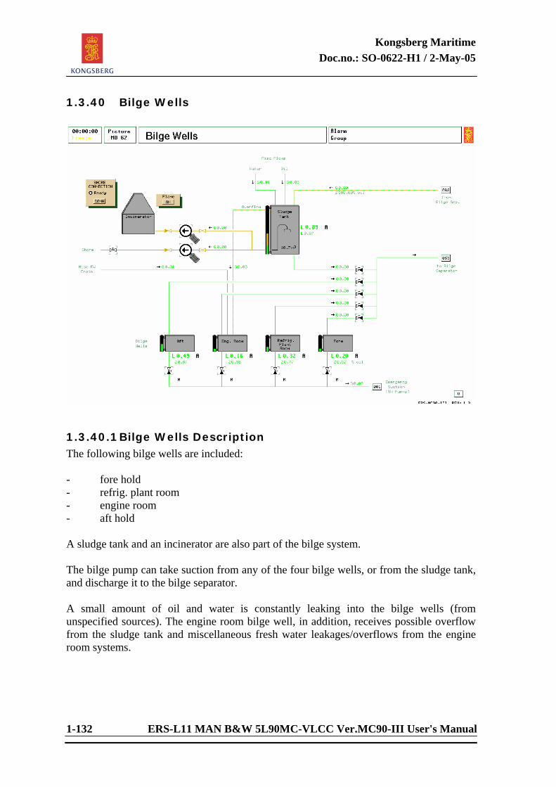
Kongsberg Maritime Doc.no.: SO-0622-H1 / 2-May-05
1-132 ERS-L11 MAN B&W 5L90MC-VLCC Ver.MC90-III User's Manual
1.3.40 Bilge Wells
1.3.40.1 Bilge Wells Description The following bilge wells are included: - fore hold - refrig. plant room - engine room - aft hold A sludge tank and an incinerator are also part of the bilge system. The bilge pump can take suction from any of the four bilge wells, or from the sludge tank, and discharge it to the bilge separator. A small amount of oil and water is constantly leaking into the bilge wells (from unspecified sources). The engine room bilge well, in addition, receives possible overflow from the sludge tank and miscellaneous fresh water leakages/overflows from the engine room systems.
Kongsberg Maritime Doc.no.: SO-0622-H1 / 2-May-05
ERS-L11 MAN B&W 5L90MC-VLCC Ver.MC90-III User's Manual 1-133
Sludge Tank The input to the sludge tank is from the following sources: - HFO purifier sludge - DO purifier sludge - LO purifier sludge - HFO settling tank 1 drain - HFO settling tank 2 drain The total water and oil input flows are summed up and displayed as two separate variables (oil, water) for convenience. Oily return flow from the bilge water separator also enters the sludge tank. The content of the sludge tank is assumed to separate immediately into oil and water. Incinerator The incinerator takes suction from the oil (top) part of the sludge tank by means of a float device. To initiate incinerator operation, start the pump and ignite the burner. If the pump light begins to flash, this flashing indicates automatic stop of the pump. Auto stop can be caused by: - no oil in the sludge tank - time out for burner ignition Flashing burner light indicates that the burner is ready for ignition.
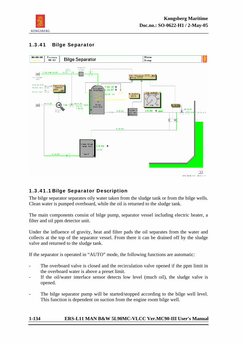
Kongsberg Maritime Doc.no.: SO-0622-H1 / 2-May-05
1-134 ERS-L11 MAN B&W 5L90MC-VLCC Ver.MC90-III User's Manual
1.3.41 Bilge Separator
1.3.41.1 Bilge Separator Description The bilge separator separates oily water taken from the sludge tank or from the bilge wells. Clean water is pumped overboard, while the oil is returned to the sludge tank. The main components consist of bilge pump, separator vessel including electric heater, a filter and oil ppm detector unit. Under the influence of gravity, heat and filter pads the oil separates from the water and collects at the top of the separator vessel. From there it can be drained off by the sludge valve and returned to the sludge tank. If the separator is operated in “AUTO” mode, the following functions are automatic: - The overboard valve is closed and the recirculation valve opened if the ppm limit in
the overboard water is above a preset limit. - If the oil/water interface sensor detects low level (much oil), the sludge valve is
opened. - The bilge separator pump will be started/stopped according to the bilge well level.
This function is dependent on suction from the engine room bilge well.
Kongsberg Maritime Doc.no.: SO-0622-H1 / 2-May-05
ERS-L11 MAN B&W 5L90MC-VLCC Ver.MC90-III User's Manual 1-135
A flashing AUTO light indicates functional failure. The cause can be high oil content (low-low oil/water interface level) or low separator temperature. The separator pump will then be stopped, the sludge valve opened and the overboard and recirculation valves closed. The heating power is turned on/off according to temperature, by a thermostatic switch as long as the main switch is on. This switch works independently of the AUTO mode. The settling process in the separator vessel is modelled to be dependent on settling time, inlet flow oil content, temperature and position of oil/water interface level.
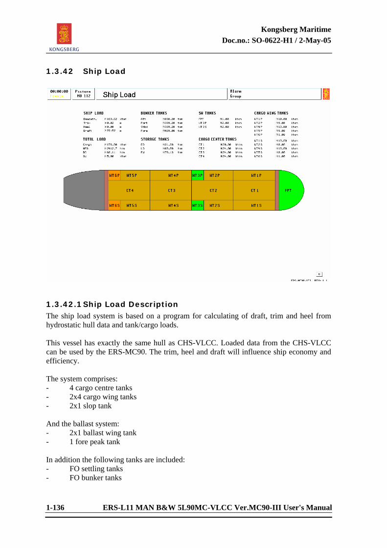
Kongsberg Maritime Doc.no.: SO-0622-H1 / 2-May-05
1-136 ERS-L11 MAN B&W 5L90MC-VLCC Ver.MC90-III User's Manual
1.3.42 Ship Load
1.3.42.1 Ship Load Description The ship load system is based on a program for calculating of draft, trim and heel from hydrostatic hull data and tank/cargo loads. This vessel has exactly the same hull as CHS-VLCC. Loaded data from the CHS-VLCC can be used by the ERS-MC90. The trim, heel and draft will influence ship economy and efficiency. The system comprises: - 4 cargo centre tanks - 2x4 cargo wing tanks - 2x1 slop tank And the ballast system: - 2x1 ballast wing tank - 1 fore peak tank In addition the following tanks are included: - FO settling tanks - FO bunker tanks
Kongsberg Maritime Doc.no.: SO-0622-H1 / 2-May-05
ERS-L11 MAN B&W 5L90MC-VLCC Ver.MC90-III User's Manual 1-137
Ship load override The instructor can override the calculated load condition through the “SHIP LOAD” parameters on variable page 9002, variable X07015. - 0 = load set by hull program, the ship load is calculated on the basis of masses (M) - 1 = load set by a percentage value, this was originally a potmeter input (P), instead
of the potmeter the value is set in the variable X06317. The heel is set to 0 in this mode. 0% is empty with no ballast, 20% is empty with standard ballast.
- 2 = the load is set to “standard full load” (F) - 3 = the load is set to “empty with standard ballast” (E) Note that changing tank contents directly from variable page 5700 have only effect when in default mode (0). Only the cargo and ballast tank contents can be changed from the variable page 5700 (3). The tanks on page (1) and (2) are calculated by the model (level and tank size).
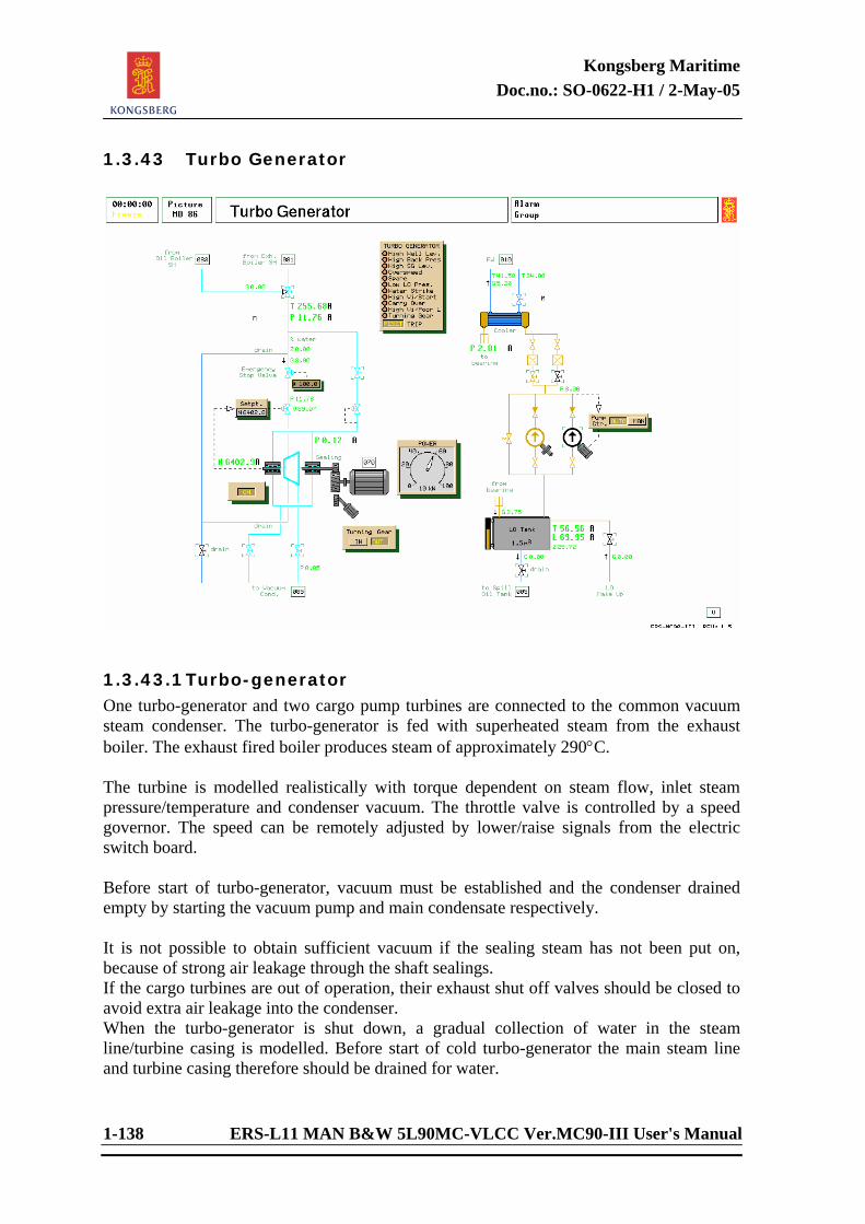
Kongsberg Maritime Doc.no.: SO-0622-H1 / 2-May-05
1-138 ERS-L11 MAN B&W 5L90MC-VLCC Ver.MC90-III User's Manual
1.3.43 Turbo Generator
1.3.43.1 Turbo-generator One turbo-generator and two cargo pump turbines are connected to the common vacuum steam condenser. The turbo-generator is fed with superheated steam from the exhaust boiler. The exhaust fired boiler produces steam of approximately 290°C. The turbine is modelled realistically with torque dependent on steam flow, inlet steam pressure/temperature and condenser vacuum. The throttle valve is controlled by a speed governor. The speed can be remotely adjusted by lower/raise signals from the electric switch board. Before start of turbo-generator, vacuum must be established and the condenser drained empty by starting the vacuum pump and main condensate respectively. It is not possible to obtain sufficient vacuum if the sealing steam has not been put on, because of strong air leakage through the shaft sealings. If the cargo turbines are out of operation, their exhaust shut off valves should be closed to avoid extra air leakage into the condenser. When the turbo-generator is shut down, a gradual collection of water in the steam line/turbine casing is modelled. Before start of cold turbo-generator the main steam line and turbine casing therefore should be drained for water.
Kongsberg Maritime Doc.no.: SO-0622-H1 / 2-May-05
ERS-L11 MAN B&W 5L90MC-VLCC Ver.MC90-III User's Manual 1-139
If the turbo-generator is started with much water present in the steam line, “water strike” will occur. This can ruin the turbine rotor. It is indicated by turbine trip due to axial displacement of rotor. The turbo-generator lub. oil tank should be drained off regularly and new oil added. Very low/high lub. oil temperature or very high water content will reduce the lubrication ability of the oil and cause trouble (high vibration trip). To start the turbine, the emergency stop valve should be manually opened slowly and the turbine run at a few hundred RPM for at least one minute if the turbine is cold. This is to reduce thermal tension during start up. If the turbine speed is taken up too fast, high vibration will occur and the turbine will trip. The turbo-generator is protected by a separate safety system, and trip signal is given on the following conditions: - high condenser water level - high condenser pressure (low vacuum) - high steam generator water level - turbo-generator overspeed - high stator temperature - low lub.oil pressure - rotor displacement (drain water strike) - high vibration (cold start) - rotor displacement (carry over water strike) - high vibration (poor lubrication)
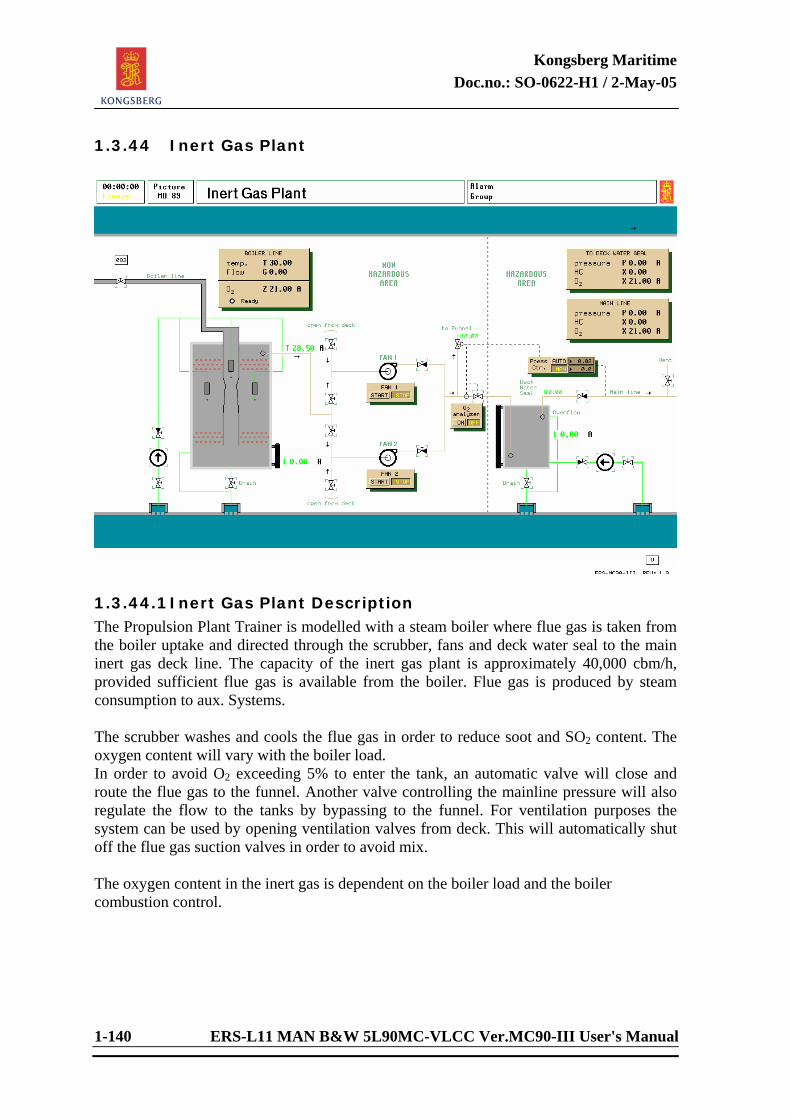
Kongsberg Maritime Doc.no.: SO-0622-H1 / 2-May-05
1-140 ERS-L11 MAN B&W 5L90MC-VLCC Ver.MC90-III User's Manual
1.3.44 Inert Gas Plant
1.3.44.1 Inert Gas Plant Description The Propulsion Plant Trainer is modelled with a steam boiler where flue gas is taken from the boiler uptake and directed through the scrubber, fans and deck water seal to the main inert gas deck line. The capacity of the inert gas plant is approximately 40,000 cbm/h, provided sufficient flue gas is available from the boiler. Flue gas is produced by steam consumption to aux. Systems. The scrubber washes and cools the flue gas in order to reduce soot and SO2 content. The oxygen content will vary with the boiler load. In order to avoid O2 exceeding 5% to enter the tank, an automatic valve will close and route the flue gas to the funnel. Another valve controlling the mainline pressure will also regulate the flow to the tanks by bypassing to the funnel. For ventilation purposes the system can be used by opening ventilation valves from deck. This will automatically shut off the flue gas suction valves in order to avoid mix. The oxygen content in the inert gas is dependent on the boiler load and the boiler combustion control.
Kongsberg Maritime Doc.no.: SO-0622-H1 / 2-May-05
ERS-L11 MAN B&W 5L90MC-VLCC Ver.MC90-III User's Manual 1-141
<This page is intentionally left blank.>
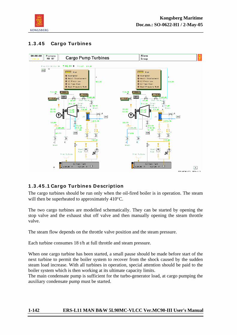
Kongsberg Maritime Doc.no.: SO-0622-H1 / 2-May-05
1-142 ERS-L11 MAN B&W 5L90MC-VLCC Ver.MC90-III User's Manual
1.3.45 Cargo Turbines
1.3.45.1 Cargo Turbines Description The cargo turbines should be run only when the oil-fired boiler is in operation. The steam will then be superheated to approximately 410°C. The two cargo turbines are modelled schematically. They can be started by opening the stop valve and the exhaust shut off valve and then manually opening the steam throttle valve. The steam flow depends on the throttle valve position and the steam pressure. Each turbine consumes 18 t/h at full throttle and steam pressure. When one cargo turbine has been started, a small pause should be made before start of the next turbine to permit the boiler system to recover from the shock caused by the sudden steam load increase. With all turbines in operation, special attention should be paid to the boiler system which is then working at its ultimate capacity limits. The main condensate pump is sufficient for the turbo-generator load, at cargo pumping the auxiliary condensate pump must be started.
Kongsberg Maritime Doc.no.: SO-0622-H1 / 2-May-05
ERS-L11 MAN B&W 5L90MC-VLCC Ver.MC90-III User's Manual 1-143
A simple safety system for the cargo turbines is modelled (common for all turbines), and cargo turbine trip is given on the following conditions: - high condenser water level - high condenser pressure - high steam generator water level - rotor displacement (by water strike) Note that the cargo pump turbines are less sensitive to low condenser vacuum than the turbo-generator. It is recommended to shut this off during cargo pumping. Cargo pump turbine trip is indicated by flashing stop valve light on local panel. The trip is reset by pressing the push button.
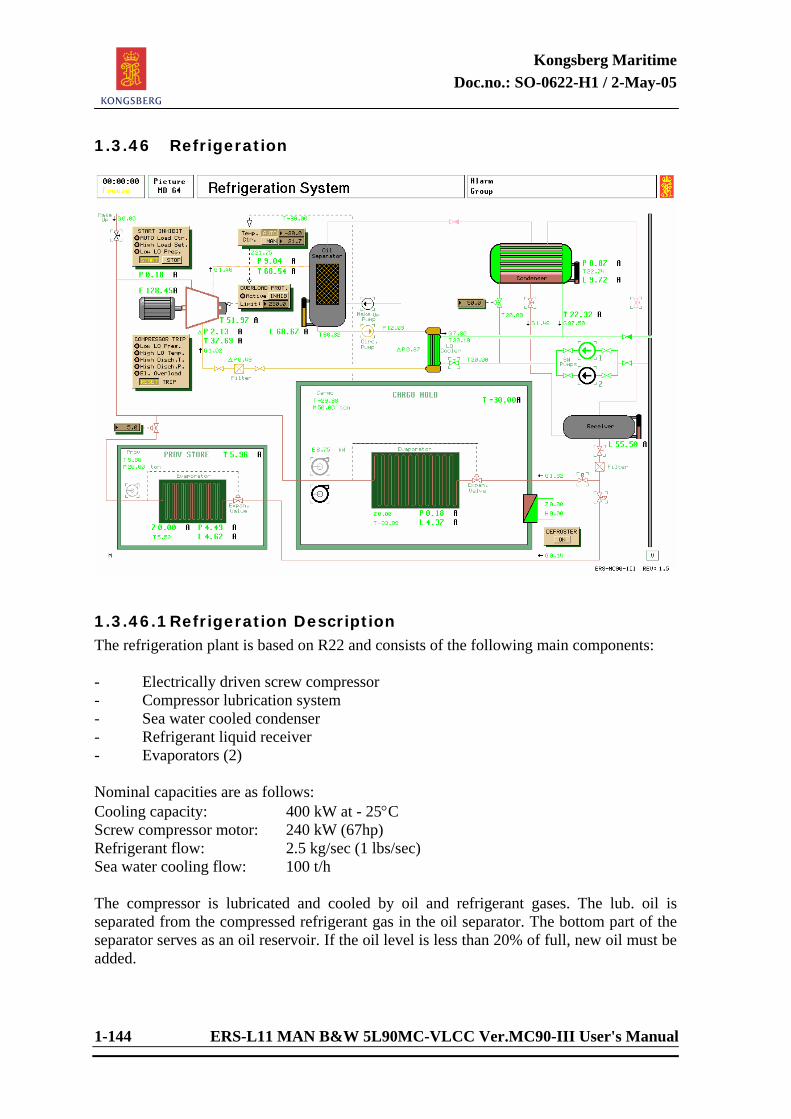
Kongsberg Maritime Doc.no.: SO-0622-H1 / 2-May-05
1-144 ERS-L11 MAN B&W 5L90MC-VLCC Ver.MC90-III User's Manual
1.3.46 Refrigeration
1.3.46.1 Refrigeration Description The refrigeration plant is based on R22 and consists of the following main components: - Electrically driven screw compressor - Compressor lubrication system - Sea water cooled condenser - Refrigerant liquid receiver - Evaporators (2) Nominal capacities are as follows: Cooling capacity: 400 kW at - 25°C Screw compressor motor: 240 kW (67hp) Refrigerant flow: 2.5 kg/sec (1 lbs/sec) Sea water cooling flow: 100 t/h The compressor is lubricated and cooled by oil and refrigerant gases. The lub. oil is separated from the compressed refrigerant gas in the oil separator. The bottom part of the separator serves as an oil reservoir. If the oil level is less than 20% of full, new oil must be added.
Kongsberg Maritime Doc.no.: SO-0622-H1 / 2-May-05
ERS-L11 MAN B&W 5L90MC-VLCC Ver.MC90-III User's Manual 1-145
A substantial part of the compressor heat is transferred to the cooling oil in the compressor screw, and the oil must be cooled. This is done by sea water in the LO cooler. The electric load on the compressor motor varies according to compressor condition, suction pressure, discharge pressure and gas flow. Electric overload will occur if the load is higher than a preset limit. The effective (internal) compression ratio of the screw compressor is adjustable by means of a suction slide valve. It is positioned by a PID controller, controlled by the refrigerated room temperature. The sea water flow to the condenser is supplied by two SW pumps. Normally just one is active, while the other is stand-by. The sea water flow can be adjusted by a throttle valve at the condenser inlet. Normally 50% valve setting is used, giving a flow of approx. 100 ton/h. The condensed refrigerate flows by gravity down to the liquid receiver. The valve called “vapor valve” is for pressure equalizing between condenser and the liquid receiver vessel. If it is closed, the draining of the condenser will be obstructed. Heat loss to surroundings is dependent on ambient temperature. At steady state condition this is the only heat load modelled, in addition to the air circulation power dissipation. To enable more versatile steady state operations, an extra heat load can be activated. This “extra load” can be interpreted as a secondary brine system cooled by the circulating air. The load setting represents the rate of flow circulation on the brine side. The additional heat flow is computed as being proportional to load setting and to the difference between the brine temperature (= 0¡C) and refrigerated air temperature. Start Inhibit: - AUTO selected : X06615 = 1 - High contrl. setting : Z06616 > 26% - Low LO Pressure : P06571 < 0.75 bar
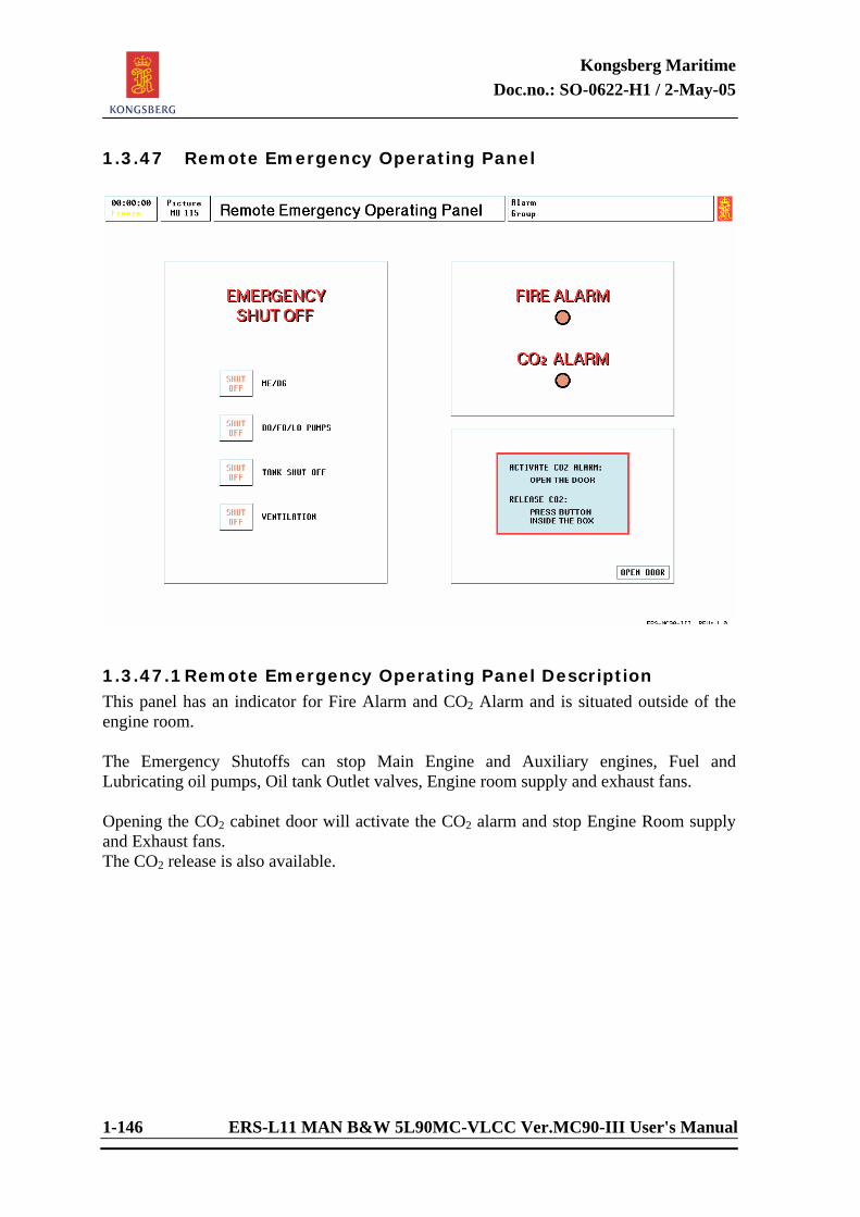
Kongsberg Maritime Doc.no.: SO-0622-H1 / 2-May-05
1-146 ERS-L11 MAN B&W 5L90MC-VLCC Ver.MC90-III User's Manual
1.3.47 Remote Emergency Operating Panel
1.3.47.1 Remote Emergency Operating Panel Description This panel has an indicator for Fire Alarm and CO2 Alarm and is situated outside of the engine room. The Emergency Shutoffs can stop Main Engine and Auxiliary engines, Fuel and Lubricating oil pumps, Oil tank Outlet valves, Engine room supply and exhaust fans. Opening the CO2 cabinet door will activate the CO2 alarm and stop Engine Room supply and Exhaust fans. The CO2 release is also available.
Kongsberg Maritime Doc.no.: SO-0622-H1 / 2-May-05
ERS-L11 MAN B&W 5L90MC-VLCC Ver.MC90-III User's Manual 1-147
1. Fire 1.1 For Engine Room fire ensure emergency generator is running. (It should start
automatically if main generators are stopped.) 1.2 Stop pumps. 1.3 Close tank outlet valves. 1.4 Engine room supply and exhaust fans may be required for smoke control if fire is
being fought by fire parties. 2. CO2 2.1 If Engine Room fire is serious it may be necessary to use the fixed installation. 2.2 Ensure all fire shut offs are operated. 2.3 Ensure engine room is battened down. 2.4 Ensure all personnel are accounted for. 2.5 Open CO2 cabinet and release CO2. 2.6 After release of CO2 the Engine Room must be allowed to cool until there is no
possibility of the fire re-igniting before re-entry.
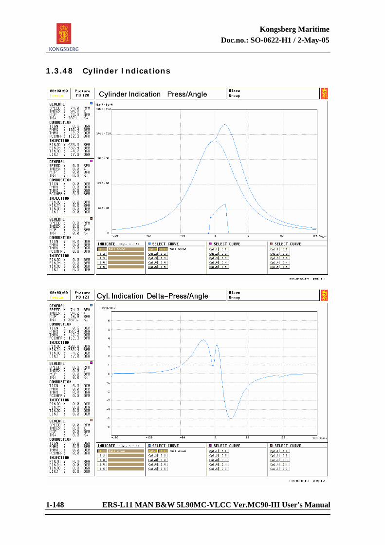
Kongsberg Maritime Doc.no.: SO-0622-H1 / 2-May-05
1-148 ERS-L11 MAN B&W 5L90MC-VLCC Ver.MC90-III User's Manual
1.3.48 Cylinder Indications
Kongsberg Maritime Doc.no.: SO-0622-H1 / 2-May-05
ERS-L11 MAN B&W 5L90MC-VLCC Ver.MC90-III User's Manual 1-149
1.3.48.1 Cylinder Indication Diagram Description Cylinder Indication Press/Angle (MD 120) This picture contains three diagrams; fuel injection, compression and combustion pressure/angle (p-a) which indicates the combustion in the cylinders during one revolution (two stroke engines). Injection diagram which is used to indicate the following parameters: Injector opening pressure (PINJO) Maximum pressure (PINJM) Injector opening time (TINJO) Lenght of injector opening time (LINJ) Compression diagram which is used to indicate the cylinder pressure (PCOMPR) without combustion (shut off fuel). Note that the PCOMPR is lower for a cylinder without combustion because this cylinder has a lower temperature. Press/angle diagram which is used to indicate compression pressures (PCOMPR) and maximum pressures (PMAX), and it illustrates clearly the pressure changes during fuel combustion. This diagram shows also the time of ignition (TIGN) and time of maximum combustion pressure (TMAX). Studies on injector faults, different fuel qualities and different injector time settings are recommended. The horizontal axis represents the crank angle. We define the top dead center (TDC) as zero, the value before TDC as minus, and the value after TDC as plus. The vertical axis represents the cylinder pressure and injection pressure. Information about Main Engine speed (SPEED), index of fuel pump (INDEX), mean indicated pressure (MIP) and indicated power (IKW) in the top left corner of picture. Information from p-a diagram: Diagram display (1): Pmax low, but Pcom normal. Deduction: Fuel injection too late. Possible causes: -- Fuel pressure too low. -- Defective fuel valve(s) or nozzles. -- Defective fuel pump suction valve or shock absorber. -- Exceptionally poor fuel (bad ignition properties). -- VIT index wrong. -- Fuel pump lead too little. Diagram display (2): Pmax high, but Pcom normal. Deduction: Fuel injection too early.
Kongsberg Maritime Doc.no.: SO-0622-H1 / 2-May-05
1-150 ERS-L11 MAN B&W 5L90MC-VLCC Ver.MC90-III User's Manual
Possible causes: -- VIT index wrong. -- Fuel pump lead too large. Diagram display (3): Both Pcom and Pmax are low. Deduction: Leakages, increased cyl.volume, or fouling. Possible causes: -- Piston ring blow-by. -- Exhaust valve leakage. -- Piston crown burnt. -- Low scavenge pressure, fouling of exhaust and/or air system. Three cylinder curves may be displayed at the same time. On the lower part of the picture, the soft button Zoom can be used to zoom the diagram 300% in horizontal direction. The soft button Spread is used to move overlaying curves apart. NOTE! When taking a cylinder indication by pressing the button I 1 to I 5, the indication represents the state of the cylinders at the time the button was pressed. Five states of the main engine can be recorded and stored. Cylinder Indication Delta-Press/Angle (MD 123) This is not a diagram normally found onboard, but is included in the simulator to illustrate the rate of pressure change related to crank angle (the numerical derivative to the Cylinder Indication Press/Angle curve). Mathematical Definition: dy/dx = lim/dx → 0 Calculate the derivative: We want to find the derivative of the curve between 60 and 90 bar for the cylinder 1 (See Cylinder Indication Press/Angle picture): By marking the curve at 60 and 90 bar (compression), and by drawing straight lines from these points to the horizontal axis we will find the corresponding angles (-30 dgr and - 20 dgr). We are now able to calculate the derivate for this part of the curve: dy/dx = 90-60/-20-(-30) = 30/10 = 3 Find the derivative by MD 123: Instead of calculating this value we can find the rate of pressure change at any crank angle by drawing a straight line from the horizontal axis to the curve. The numeric value is then read on the vertical axis. Three cylinder curves may be displayed at the same time.
Kongsberg Maritime Doc.no.: SO-0622-H1 / 2-May-05
ERS-L11 MAN B&W 5L90MC-VLCC Ver.MC90-III User's Manual 1-151
<This page is intentionally left blank>
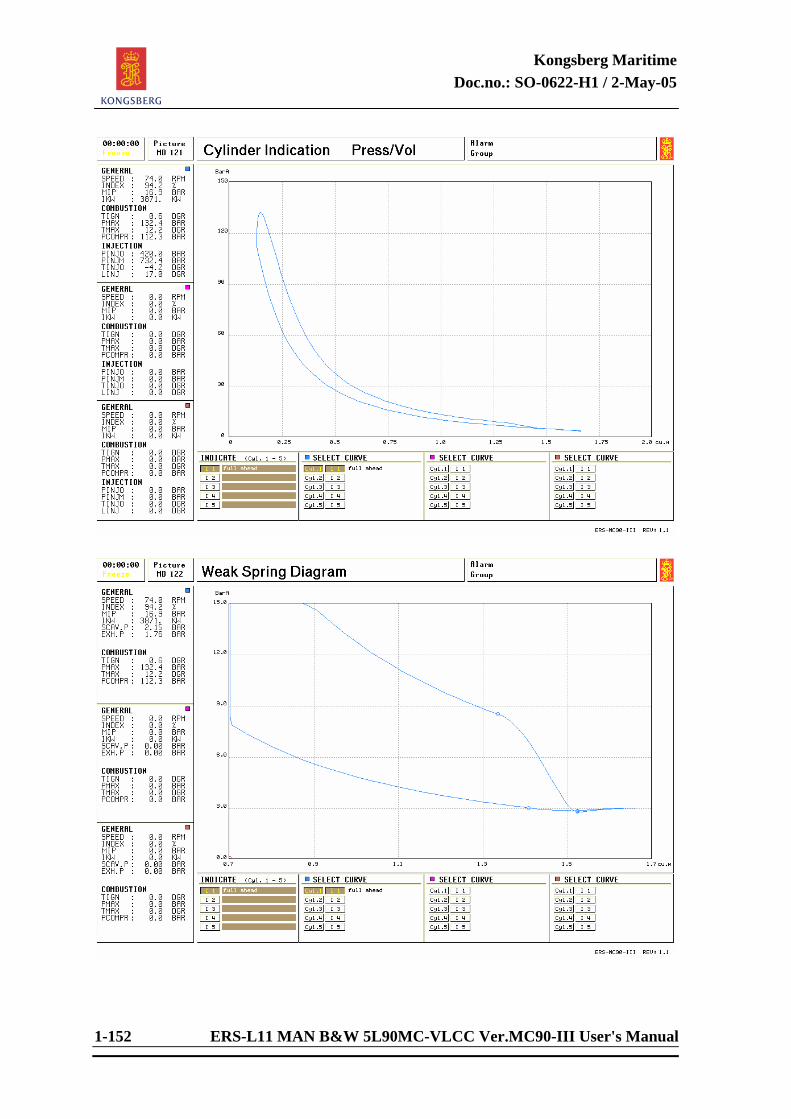
Kongsberg Maritime Doc.no.: SO-0622-H1 / 2-May-05
1-152 ERS-L11 MAN B&W 5L90MC-VLCC Ver.MC90-III User's Manual
Kongsberg Maritime Doc.no.: SO-0622-H1 / 2-May-05
ERS-L11 MAN B&W 5L90MC-VLCC Ver.MC90-III User's Manual 1-153
Cylinder Indication Press/Vol (MD 121) This diagram illustrates the pressure variations in the engine cylinder. The diagram area can be integrated and the mean indicated pressure calculated. The power developed in the particular cylinder can then be found by multiplying the engine speed with the cylinder constant. The horizontal axis represents the volume of the cylinder, and the vertical axis represents the cylinder pressure. Data Indication of cylinders: As for Cylinder Indication Press/Angle. Information from p-v diagram: As for Cylinder Indication Press/Angle. Three cylinder curves may be displayed at the same time. Weak Spring Diagram (MD 122) This is not a diagram normally found onboard vessels with 2 stroke engines but is included in the simulator as we consider it as a useful tool from a pedagogical point of view. By using the weak spring diagram, we are able to have a closer look at the lower pressures of the exhaust gas and the scavenging air and the moment of “gas change”. Data Indication of cylinders: In addition to the combustion data, there are readings for scavenging air and exhaust gas pressure. On the lower part of the picture, the soft button Zoom 1 can be used to zoom the diagram 300% in vertical position. Zoom 2 is used to zoom the diagram 600% in vertical position. Three cylinder curves may be displayed at the same time.

Kongsberg Maritime Doc.no.: SO-0622-H1 / 2-May-05
ERS-L11 MAN B&W 5L90MC-VLCC Ver.MC90-III User's Manual
OPERATION
of
ERS-L11 MAN B&W 5L90MC-VLCC Version MC90-III
ENGINE ROOM SYSTEMS

Kongsberg Maritime Doc.no.: SO-0622-H1 / 2-May-05
ERS-L11 MAN B&W 5L90MC-VLCC Ver.MC90-III User's Manual 2-1
2 GENERAL INFORMATION 2.1 Operation of the Propulsion Plant Trainer The main objective in the following sections, is to describe the start-up procedure for all
subsystems included in the Propulsion Plant Trainer. To describe all the subsystems, we feel it is an advantage to start with a dead ship condition, where all subsystems are shut down.
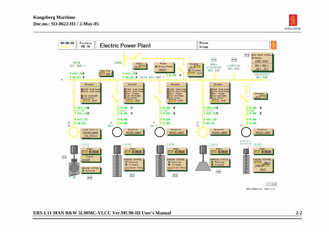
Kongsberg Maritime Doc.no.: SO-0622-H1 / 2-May-05
ERS-L11 MAN B&W 5L90MC-VLCC Ver.MC90-III User's Manual 2-2
Kongsberg Maritime Doc.no.: SO-0622-H1 / 2-May-05
ERS-L11 MAN B&W 5L90MC-VLCC Ver.MC90-III User's Manual 2-3
2.1.1 Shore Power Related systems required to be in operation:
None. Preparations before connecting "Shore Power": The shore power can also be operated from the main switchboard’s shore power section (if
main switchboard is installed). Select picture “Electric Power Plant”. Press IN button on the CABLE panel. If the phase is wrong (WRONG PHASE lamp on PHASE panel lit), press button TWIST. If
the breaker is tripped (TRIPPED lamp on shore BREAKER panel lit), press button RESET. Starting procedure: MANUAL mode: Press button IN on the shore BREAKER panel.
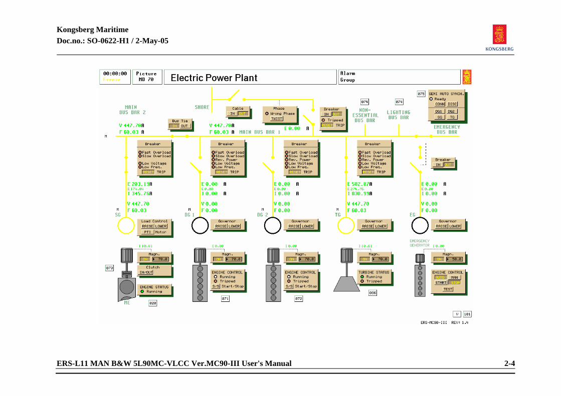
Kongsberg Maritime Doc.no.: SO-0622-H1 / 2-May-05
ERS-L11 MAN B&W 5L90MC-VLCC Ver.MC90-III User's Manual 2-4
Kongsberg Maritime Doc.no.: SO-0622-H1 / 2-May-05
ERS-L11 MAN B&W 5L90MC-VLCC Ver.MC90-III User's Manual 2-5
2.1.2 Emergency Generator Related systems required to be in operation: None. Preparations before connecting "Emergency generator": Select picture “Electric Power Plant”. The Emergency generator can also be started and connected on the main switchboard´s
“Emergency Gen.” section. Starting procedure: MANUAL mode: Press button START on ENGINE CONTROL panel. Press button IN on emergency generator BREAKER panel. If shore power is connected, disconnect it by pressing the OUT button on the shore
BREAKER panel. AUTO mode: Press button AUTO on the ENGINE CONTROL panel. When the emergency generator is connected, only the consumers connected to the
emergency bus bar can be started. Normally, the control of the emergency generator is set in AUTO mode, the engine will then start automatically in case of a “black out”.
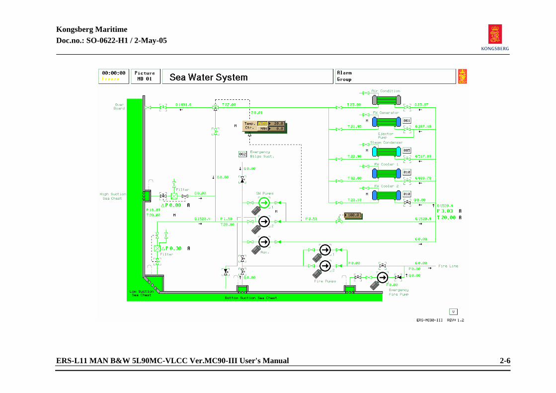
Kongsberg Maritime Doc.no.: SO-0622-H1 / 2-May-05
ERS-L11 MAN B&W 5L90MC-VLCC Ver.MC90-III User's Manual 2-6
Kongsberg Maritime Doc.no.: SO-0622-H1 / 2-May-05
ERS-L11 MAN B&W 5L90MC-VLCC Ver.MC90-III User's Manual 2-7
2.1.3 Sea Water System Related systems required to be in operation: Shore Power, Emergency generator or an auxiliary generator connected to the switchboard. Preparations before operating "Sea Water System": Select picture “Sea Water System”. The Sea water pumps can also be started from the “PowerChief” panel’s pump section (if
diesel generator(s) is running and connected). Open one of three sea water pump suction valves from sea chests. Open sea water discharge overboard valve. Open valves before and after coolers/condensers.
Open sea water recirculation valve. Open sea water inlet valve(s) to cooler(s). Air cond cooler, Fresh water generator, steam condenser and one Fresh Water Cooler.
Select MAN or AUTO position on the sea water temp controller, and set to a suitable
temperature. (Should be slightly above sea water ambient temperature.) Auxiliary sea water pump is connected to emergency bus bar.
Adjust outlet pressure controller to a desired flow (not valid for aux. SW pump).
Kongsberg Maritime Doc.no.: SO-0622-H1 / 2-May-05
ERS-L11 MAN B&W 5L90MC-VLCC Ver.MC90-III User's Manual 2-8
Starting procedure: MANUAL mode: Start SW pump(s). AUTO (STAND BY START) mode: NOTE! This mode is only available when diesel generator(s) is running and connected. Select the picture “Power Chief - Pump/Compr. Control”. Press the button AUTO on the SEA WATER PUMPS panel. If the pump in service stops,
the “stand by” pump will start only if the AUTO mode is selected. If in an emergency situation, emergency suction can be used to empty engine room bilges with sea water pump or fire pump. Emergency suction also from cargo holds and sludge tank. Open emergency suction and overboard from pumps, and start pump.

Kongsberg Maritime Doc.no.: SO-0622-H1 / 2-May-05
ERS-L11 MAN B&W 5L90MC-VLCC Ver.MC90-III User's Manual 2-9
<This page is intentionally left blank>
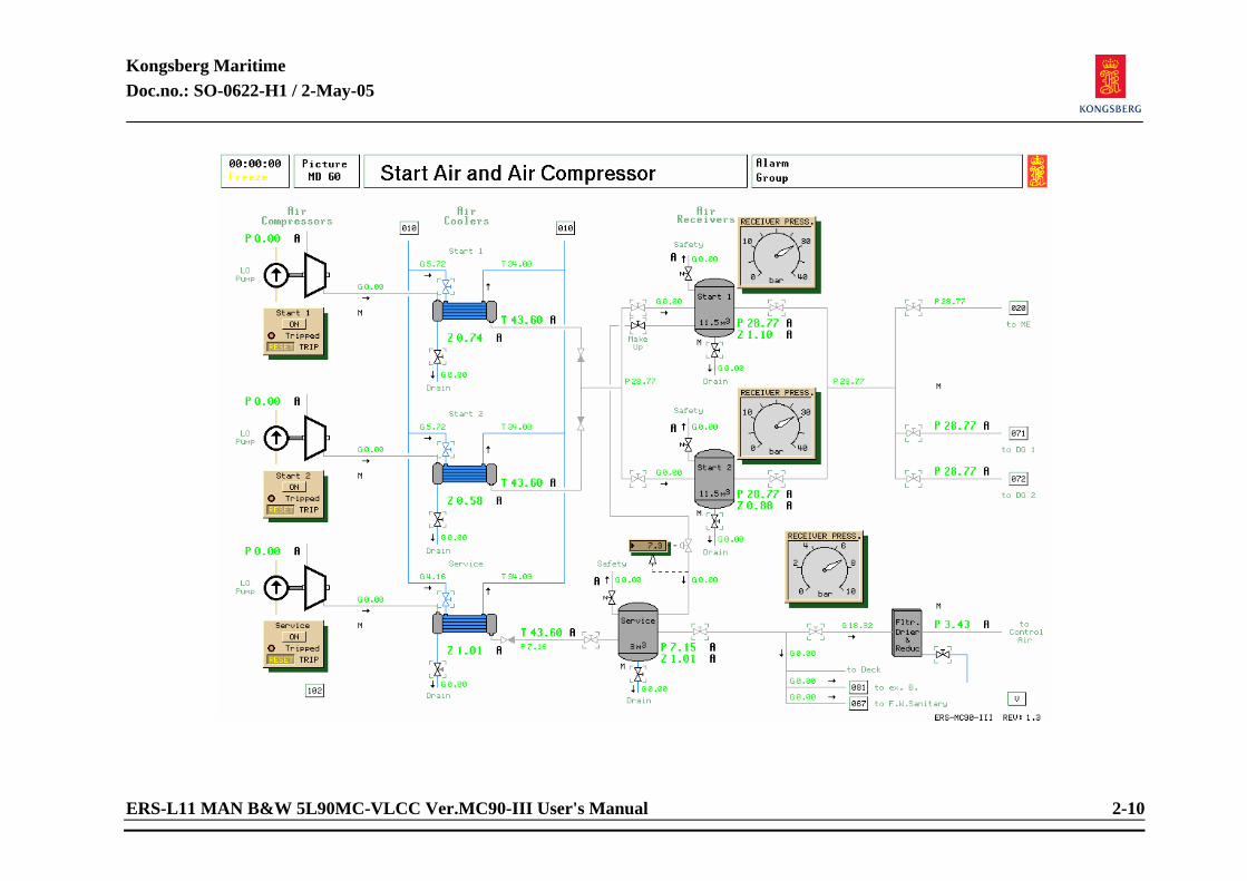
Kongsberg Maritime Doc.no.: SO-0622-H1 / 2-May-05
ERS-L11 MAN B&W 5L90MC-VLCC Ver.MC90-III User's Manual 2-10
Kongsberg Maritime Doc.no.: SO-0622-H1 / 2-May-05
ERS-L11 MAN B&W 5L90MC-VLCC Ver.MC90-III User's Manual 2-11
2.1.4 Start Air and Air Compressor Related systems required to be in operation:
Main Sea Water and FW system in operation. Operation as an isolated system is not available.
Preparations before starting "Starting air compressor":
Select picture Fresh Water System and open valve to Air compressor coolers. Select picture “Start Air and Air Compressor”. The Starting air compressor can also be started from the "PowerChief" panel’s compressor section (if diesel generator(s) is running and connected). When starting from shore power or emergency generator, only start air compressor 2 can be started. Open FW inlet valve(s) to start air cooler(s) Drain start air cooler(s) Open air inlet valve(s) to start air receiver(s) Open air outlet valve(s) from start air receiver(s) Drain start air receiver(s) When pressure is obtained, open air supply valve(s) to selected consumer(s)
Starting procedure: MANUAL mode:
If the selected compressor is tripped (TRIPPED lamp lit), press RESET button on the compressor panel. Start the compressor by pressing button ON. Close drain valves.
Kongsberg Maritime Doc.no.: SO-0622-H1 / 2-May-05
ERS-L11 MAN B&W 5L90MC-VLCC Ver.MC90-III User's Manual 2-12
AUTO mode: Close drain valves. Select picture “Power Chief Pump/Compressor Control”. Press AUTO on the selected START AIR COMPRESSOR panel.
Preparations before starting "Service air compressor":
Select picture “Start Air and Air Compressor”. Open FW inlet valve to service air cooler. Drain service air cooler. Open air inlet valve to service air receiver. Open air outlet valve from service air receiver. Open air inlet valve to service air filter and dryer. Drain service air dryer.
Starting procedure: MANUAL mode:
If the service air compressor is tripped (TRIPPED lamp lit), press RESET button on the compressor panel. Start the compressor by pressing button ON. Close service air make-up valve from start air receiver no.1(see note). Close drain valves.
AUTO mode: Close drain valves. Select picture “Power Chief Pump/Compressor Control”. Press button AUTO on the SERVICE AIR COMPRESSOR panel. The service air compressor in this system is normally called an “instrument air compressor” and is usually of the “oil free” type. In addition there is often a “working air compressor” supplying consumers not including delicate instrument systems.
Kongsberg Maritime Doc.no.: SO-0622-H1 / 2-May-05
ERS-L11 MAN B&W 5L90MC-VLCC Ver.MC90-III User's Manual 2-13
Under certain conditions starting air compressors “produce” a considerable amount of water. The starting air also contains a small amount of oil. This will gradually reduce the efficiency of the air dryer/cooler and is therefore not desirable. The air make-up valve is usually left open for safety reasons. If the service air compressor trips, service air pressure is not lost, but supplied through the starting air receivers. This may prevent a serious situation like a shutdown of the main engine. The valve is normally pressure controlled, with an opening setpoint set slightly lower than the auto start setpoint of the service air compressor. This prevents “dirty” air from the starting air compressors to enter the control air system during normal operating conditions. Carefully consider if or when to close the service air make-up valve.
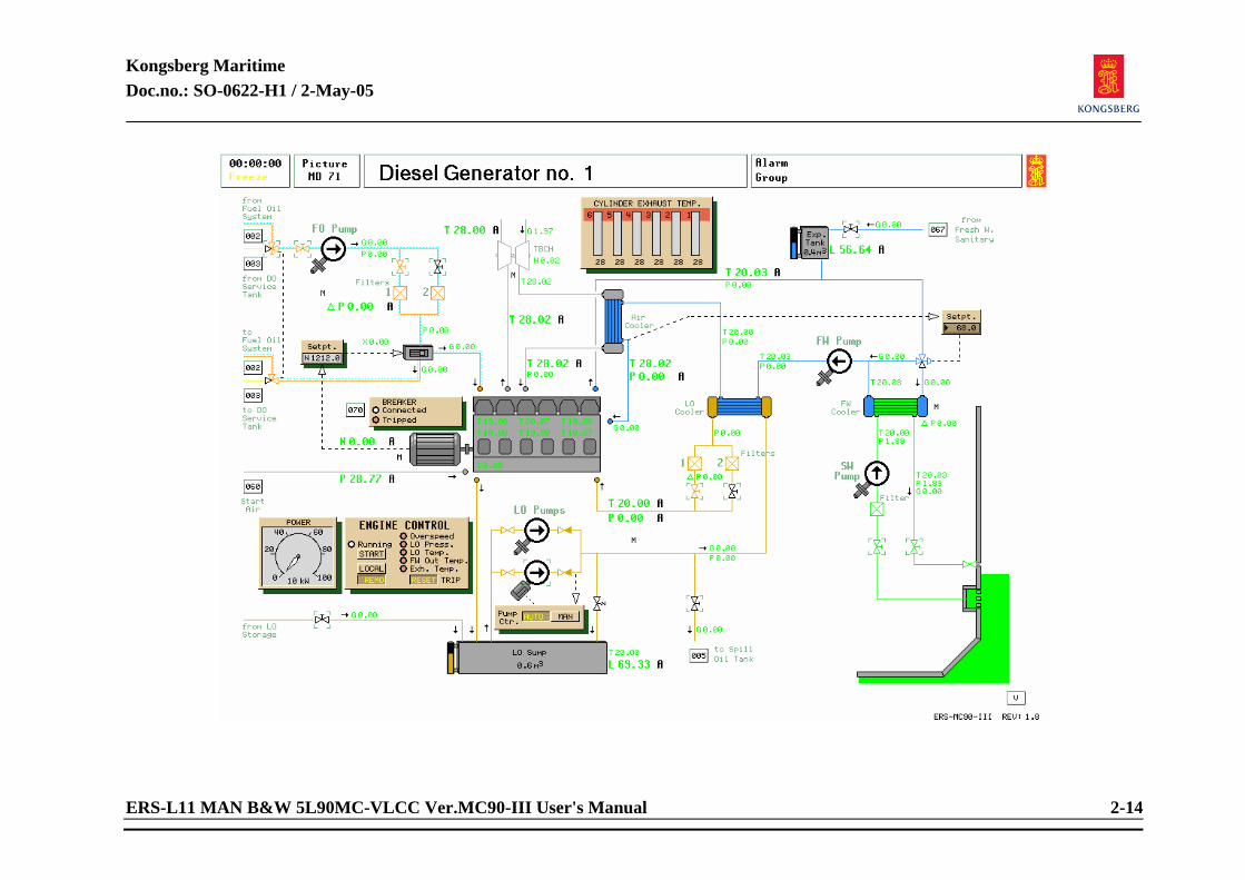
Kongsberg Maritime Doc.no.: SO-0622-H1 / 2-May-05
ERS-L11 MAN B&W 5L90MC-VLCC Ver.MC90-III User's Manual 2-14
Kongsberg Maritime Doc.no.: SO-0622-H1 / 2-May-05
ERS-L11 MAN B&W 5L90MC-VLCC Ver.MC90-III User's Manual 2-15
2.1.5 Diesel Generator no. 1 and 2 Related systems required to be in operation:
Emergency Bus Bar active. Start Air Compressors, with a minimum of 15 bar (218 psi) pressure on the starting air line and DG air supply valve open. Sufficient level in the fuel oil service tanks. Operation as an isolated system is not available.
Preparations before starting the first "Diesel generator":
Select picture “Fuel Oil Service Tanks”. All diesel generators can be started from the “PowerChief” panel’s generator section. Check water level in the fuel oil service tanks and drain if necessary (md03). Ensure that DO supply valve to generator engine(s) (md03) is open. Select picture “Diesel Generator no. 1 (or no. 2)”. Check level in LO sump tank, refill from storage tank if necessary. Ensure that lub. oil valve to spill oil tank is closed. Open lub. oil valve(s) after lub. oil filter(s). Check level in expansion tank and refill if necessary. Open SW pump suction valve from sea chest. Open sea water discharge valve (overboard after cooler). Open FO valve(s) before FO filter(s). Open FO inlet valve to FO pump. Check that three way valve is open for DO.
Kongsberg Maritime Doc.no.: SO-0622-H1 / 2-May-05
ERS-L11 MAN B&W 5L90MC-VLCC Ver.MC90-III User's Manual 2-16
Start the electrically driven LO pump (priming pump), and check that the lub. oil pressure is increasing. Set the electric LO pump in AUTO mode by pressing the AUTO button on the PUMP. CTR. panel. If the lamp TRIPPED on the BREAKER panel is lit, reset the breaker by pressing the button RESET. If any of the alarm lamps (red) are lit, press the RESET button. Press the button LOCAL on the ENGINE CONTROL panel.
Starting procedure for the first "Diesel Generator": MANUAL mode:
If the starting air pressure is above 15 bar (218 psi), the engine is ready to be started. Press START button on the ENGINE CONTROL panel. If start is carried out from the PowerChief Generator Panel, the engine control has to be set to Remote control.
The lub. oil priming pump may be set directly in AUTO mode. FW controller setpoint is normally set to 75-80°C, depending on the engine type.
Modern engines are normally operating on “blended” or heavy fuel oil. On the fuel/blended oil engines, diesel is only used to prepare the engine for repair (overhaul), or when steam is not available.
When steam is available and sufficient temperature on the HFO, changing to HFO is carried out by opening the HFO supply valves (MD03) and changing position on the three way valve (MD71-72).

Kongsberg Maritime Doc.no.: SO-0622-H1 / 2-May-05
ERS-L11 MAN B&W 5L90MC-VLCC Ver.MC90-III User's Manual 2-17
<This page is intentionally left blank>

Kongsberg Maritime Doc.no.: SO-0622-H1 / 2-May-05
ERS-L11 MAN B&W 5L90MC-VLCC Ver.MC90-III User's Manual 2-18
Kongsberg Maritime Doc.no.: SO-0622-H1 / 2-May-05
ERS-L11 MAN B&W 5L90MC-VLCC Ver.MC90-III User's Manual 2-19
Connecting the first Diesel Generator: Related systems required to be in operation: Corresponding diesel engine running. Connecting procedure for the first generator: MANUAL mode:
Select picture “Electric Power Plant” (The engines may also be started from this picture, if in REMOTE mode). Locate the panels of the running engine. Ensure that “magnetization” is ON. Adjust frequency by pressing the buttons RAISE/LOWER on the LOAD CONTRL panel until the reading of the network frequency is slightly above 60 Hz. If tripped, reset the BREAKER panel by pressing the button RESET on the BREAKER panel. Press the IN button on the BREAKER panel. Readjust the frequency, if necessary. If the shore connection is connected, disconnect it by pressing the button OUT on the shore BREAKER and the CABLE panels. The emergency generator is automatically disconnected in both AUTO and MAN mode.
AUTO/STAND BY mode: Is only permitted when at least one generator is connected.
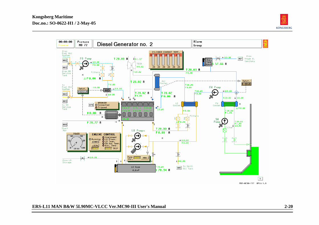
Kongsberg Maritime Doc.no.: SO-0622-H1 / 2-May-05
ERS-L11 MAN B&W 5L90MC-VLCC Ver.MC90-III User's Manual 2-20
Kongsberg Maritime Doc.no.: SO-0622-H1 / 2-May-05
ERS-L11 MAN B&W 5L90MC-VLCC Ver.MC90-III User's Manual 2-21
Starting the second Diesel Generator: Related systems required to be in operation:
Start Air Compressors, with a minimum of 15 bar (218 psi) pressure on the Starting air line and DG air supply valve open. Sufficient level in the FO oil service tanks.
Operation as an isolated system is not available.
Preparations before starting the second "Diesel generator":
Select picture “Diesel Generator no. 1 (or no. 2)”. Check level in LO sump tank, refill from storage tank if necessary. Close lub. oil valve to spill oil tank. Open lub. oil valve(s) after lub. oil filter(s). Check level in expansion tank and refill if necessary. Open SW pump suction valve from sea chest. Open sea water discharge valve (overboard after cooler). Open FO valve(s) before FO filter(s). Open FO inlet valve to FO pump. Start the electrically driven LO pump (priming pump), and check that the lub. oil pressure is increasing. Set the electric LO pump in auto mode by pressing the AUTO button on the PUMP. CTR. Panel. If the lamp TRIPPED on the Engine Control panel is lit, reset by pressing the button RESET.

Kongsberg Maritime Doc.no.: SO-0622-H1 / 2-May-05
ERS-L11 MAN B&W 5L90MC-VLCC Ver.MC90-III User's Manual 2-22
Kongsberg Maritime Doc.no.: SO-0622-H1 / 2-May-05
ERS-L11 MAN B&W 5L90MC-VLCC Ver.MC90-III User's Manual 2-23
Starting procedure for the second "Diesel Generator": MANUAL mode:
If the starting air pressure is above 15 bar(218 psi), the engine is ready to be started. Press START button on the ENGINE CONTROL panel if in Local mode. May be started both from MD70 and MD101 when in Remote mode.
AUTO mode:
Ref: Connecting the second diesel generator. Connecting the second Diesel Generator: Related systems required to be in operation:
Corresponding diesel engine running. Connecting procedure for the second generator: SEMI AUTO SYNCHRONIZING:
Select picture “Electric Power Plant” (The engines may also be started from this picture, if in REMOTE mode). Locate the panels of the started engine. Check if the button ON on the MAGN panel is active (ON). If not, press it now. Press the button RESET on the BREAKER panel, if necessary. Press button D62 on the SEMI AUTO SYNCH. Panel. Adjust voltage and frequency until Ready lamp is lit. Press connect button. If the breaker is not connecting, fine adjustment of frequency and voltage may be necessary until breaker connects.
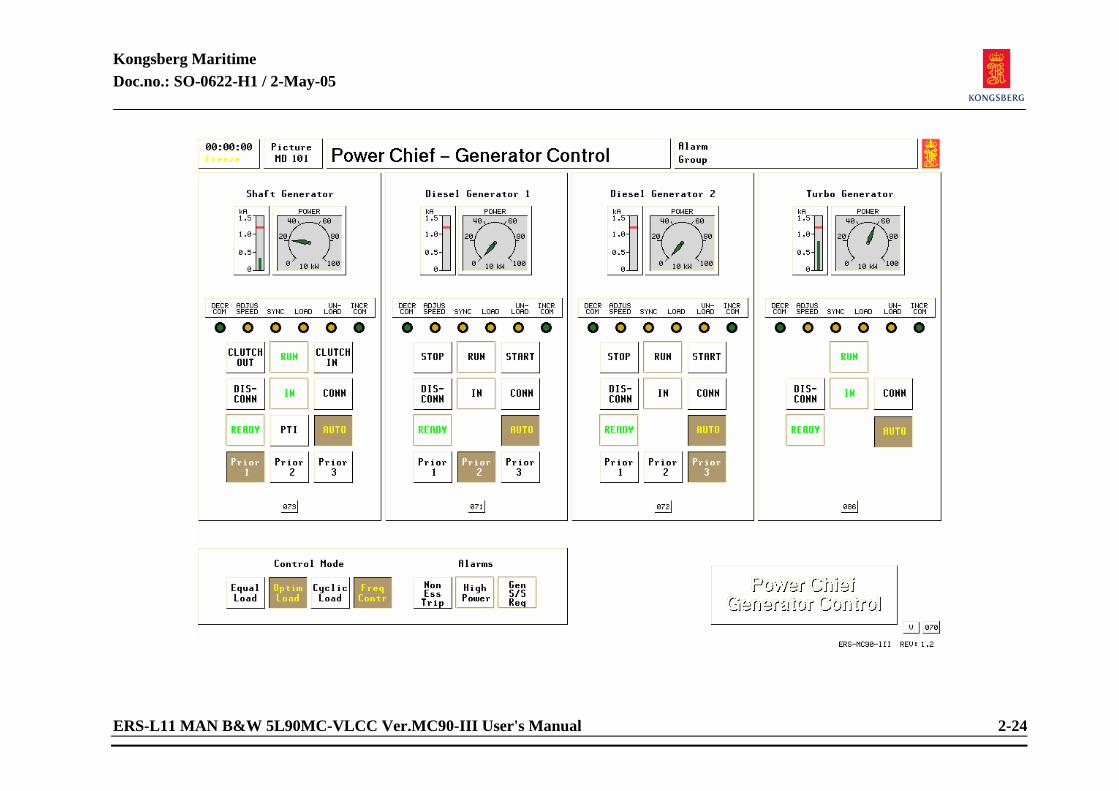
Kongsberg Maritime Doc.no.: SO-0622-H1 / 2-May-05
ERS-L11 MAN B&W 5L90MC-VLCC Ver.MC90-III User's Manual 2-24
Kongsberg Maritime Doc.no.: SO-0622-H1 / 2-May-05
ERS-L11 MAN B&W 5L90MC-VLCC Ver.MC90-III User's Manual 2-25
AUTO/STAND BY mode: Press button REMO on the ENGINE CONTROL panel. Select picture “Power Chief - Generator Control”. Locate DIESEL GENERATOR panels and check that the READY lamps on the running diesels are lit. Press buttons AUTO on the panels. To get READY indication, the diesel must be in remote mode and possible alarms must be acknowledged.
Priorities The PRIOR (priority) buttons determine the starting/stopping sequence of the diesel generators (in AUTO mode). Select the desired priority by pressing one button in each panel. Normal priority solution is: 1: Shaft Generator 2: Diesel Generator 1 3: Diesel Generator 2 The Turbo-generator should be started/connected whenever possible. It has formally always highest priority when in AUTO.
Control Mode Desired load sharing is selected by pressing the buttons on the CONTROL MODE panel.
Equal Load
Is normally selected when safety is the most important issue (during manoeuvring, loading, discharging etc.).
Optim Load (optimum load)
Is selected for economy, usually during sea voyages. Diesel(s) is running at max. Load. First priority takes “max load” while second priority takes the rest of the load. Refer to chapter 4.
Kongsberg Maritime Doc.no.: SO-0622-H1 / 2-May-05
ERS-L11 MAN B&W 5L90MC-VLCC Ver.MC90-III User's Manual 2-26
Cyclic Load (cycling load) Is selected when it is necessary to run more than one diesel on low power. This mode will cycle the load between the engines in such way that one of the diesels is running at max. load while the other diesel handles the remaining load and thereby prevents coxing of the cylinders, valves etc.
Freqr Contr (frequency control) Is selected to automatically perform network frequency control. This mode is normally always selected in addition to one of the above mentioned modes.

Kongsberg Maritime Doc.no.: SO-0622-H1 / 2-May-05
ERS-L11 MAN B&W 5L90MC-VLCC Ver.MC90-III User's Manual 2-27
<This page is intentionally left blank>
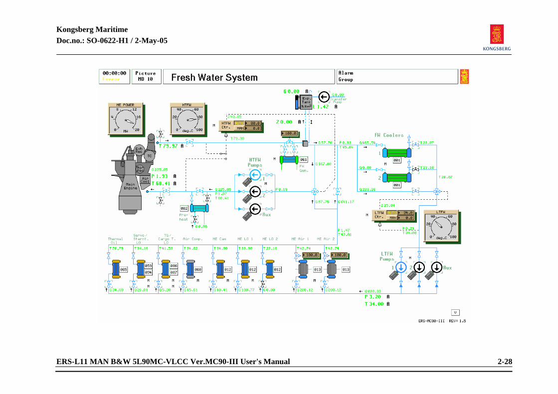
Kongsberg Maritime Doc.no.: SO-0622-H1 / 2-May-05
ERS-L11 MAN B&W 5L90MC-VLCC Ver.MC90-III User's Manual 2-28
Kongsberg Maritime Doc.no.: SO-0622-H1 / 2-May-05
ERS-L11 MAN B&W 5L90MC-VLCC Ver.MC90-III User's Manual 2-29
2.1.6 ME Freshwater System Related systems required to be in operation:
Main bus bar to be active.
Main sea water system. Preparations before starting "ME Freshwater System":
Select picture Sea Water System and ensure that valves are opened to one cooler. The Fresh water pumps can also be started from the “PowerChief” panel’s pump section.
Select ME fresh water system and open valves before and after high temperature fresh water
pumps. Open valves before and after low temperature fresh water pumps. Open valves before and
after desired coolers/condensers: - Thermal Oil (MD65)
- Stern tube LO cooler (MD54)/ Propeller servo oil cooler(MD53) - Turbogenerator/Cargo Turbines LO cooler (MD86/87) - Air compressor coolers (MD60) - Main engine LO coolers (MD12) and cam shaft LO cooler (MD12) - Main engine turbo-charger coolers (MD13)
Refill expansion tank if needed by starting FW transfer pump until sufficient level is
obtained. If fresh water coolant is cold when filling, risk of overflowing when water is heating, must be observed.
Kongsberg Maritime Doc.no.: SO-0622-H1 / 2-May-05
ERS-L11 MAN B&W 5L90MC-VLCC Ver.MC90-III User's Manual 2-30
NOTE! Only valves with drawn handles can be opened, generally coolers can be closed off with inlet valves. When inlet valves are closed, cooler is sealed off for cleaning attempt. Where two coolers are placed under one symbol, check with respective pictures to ensure that valves are actually opened.
Starting procedure: MANUAL mode:
HTFW controller and LTFW controller in MANUAL. Start selected fresh water pumps, one for high and one for low temperature systems. Set controllers to appropriate temperature. High temp: 80°C. (As guide only) Low temp: 35°C (As guide only). If starting circulation from “cold ship” status, heat water with steam heater by opening valve on heater. Circulate with aux pump until main engine is sufficiently hot to be started. Set flow controllers for Turbo-charger air coolers main engine to desired flow. Observe scavenging air temperature after main engine start to avoid condensation if temperature drops below dew point.
AUTO mode:
Preparation as in MANUAL. Select AUTO on controller after setting temperature setting to a suitable temperature. Select picture Power Chief/Pump-Compressor Control and press AUTO for HTFW pumps and LTFW pumps. Aux pumps are not part of stand by start panel. Close steam preheater after engine start. During stay in port, auxiliary pump is sufficient for cooling.
Kongsberg Maritime Doc.no.: SO-0622-H1 / 2-May-05
ERS-L11 MAN B&W 5L90MC-VLCC Ver.MC90-III User's Manual 2-31
<This page is intentionally left blank>

Kongsberg Maritime Doc.no.: SO-0622-H1 / 2-May-05
ERS-L11 MAN B&W 5L90MC-VLCC Ver.MC90-III User's Manual 2-32
Kongsberg Maritime Doc.no.: SO-0622-H1 / 2-May-05
ERS-L11 MAN B&W 5L90MC-VLCC Ver.MC90-III User's Manual 2-33
2.1.7 Electric Power Plant Related systems required to be in operation:
Aux. Engines are ready and in remote control. Preparations before starting:
All generator breakers can be connected from the main switchboard’s generator section. Magnetization must be ON and set to a value were output voltage is 440 volt. Load control must be operated RAISE or LOWER to obtain 60 Hertz. Breakers to be RESET if necessary.
Starting procedure: MANUAL mode:
Diesel engines can be started/stopped by pressing the S/S button if they are in Remote control. Turbo-generator, Diesel generators, shaft generator or emergency generator can be connected to bus bar by pressing the desired generator to be connected on the SEMI AUTO SYNCH. Panel. Adjust frequency and voltage until Ready lamp is lit. Press connect button. Readjust voltage and frequency until breaker connects. Synchronization is not modelled when connecting generators from Electric Power Plant picture. Bus Tie IN or OUT depending on load. Note! As a general rule, when manoeuvring or running heavy consumers on deck, shaft generator is separated from Main Switchboard to carry this load alone. See Emergency Generator and Shore Power for detailed instruction for these.
AUTO mode: See operation of PowerChief (MD101).
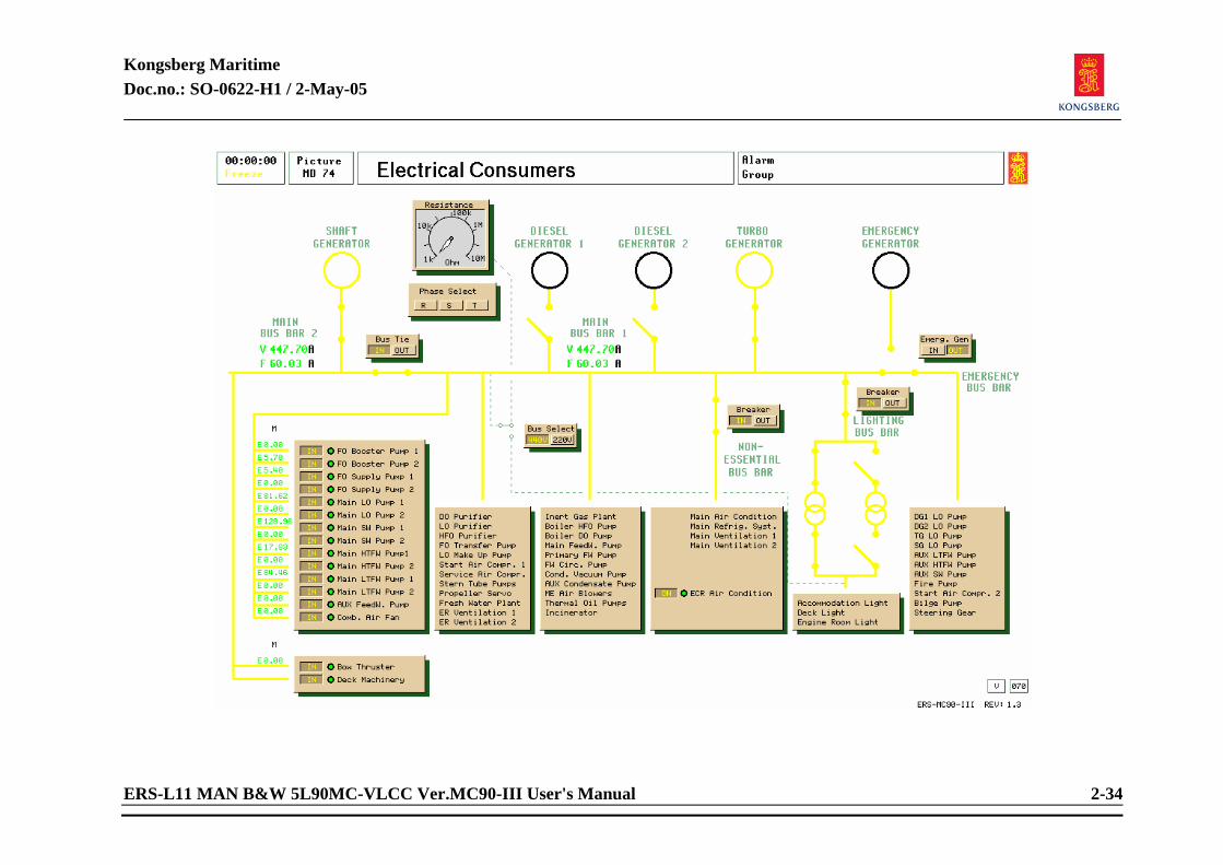
Kongsberg Maritime Doc.no.: SO-0622-H1 / 2-May-05
ERS-L11 MAN B&W 5L90MC-VLCC Ver.MC90-III User's Manual 2-34
Kongsberg Maritime Doc.no.: SO-0622-H1 / 2-May-05
ERS-L11 MAN B&W 5L90MC-VLCC Ver.MC90-III User's Manual 2-35
2.1.8 Electrical Consumers Related systems required to be in operation:
Main bus bar to be active. Operating procedure: MANUAL mode:
Selected consumers are represented with their main breakers. Pressing buttons IN will toggle breakers IN / OUT. If, in other system pictures, a pump will not start when activated, main breaker may be switched OFF. Select picture Electrical Consumers and toggle breaker ON on selected pump. Button will change colour when breaker is ON. Bus tie switch and emergency generator breaker can be operated from this picture. Main bus bar 2 can be separated from main bus bar 1 when conditions demand this. The Main Air con., Main Refrig. Syst., Main Ventilation 1 & 2 are available from the variable pages and are meant for simulating electric load. The ECR air condition is ready for connection when the green led is lit (SW pressure more than 0,5 BAR and valve to cooler is open). Lighting bus bar can be connected when breakers to transformers are connected (from variable page 7007). Testing of isolation impedance can be checked selecting 220/440 V plant and then each phase against earth by pressing the corresponding button.
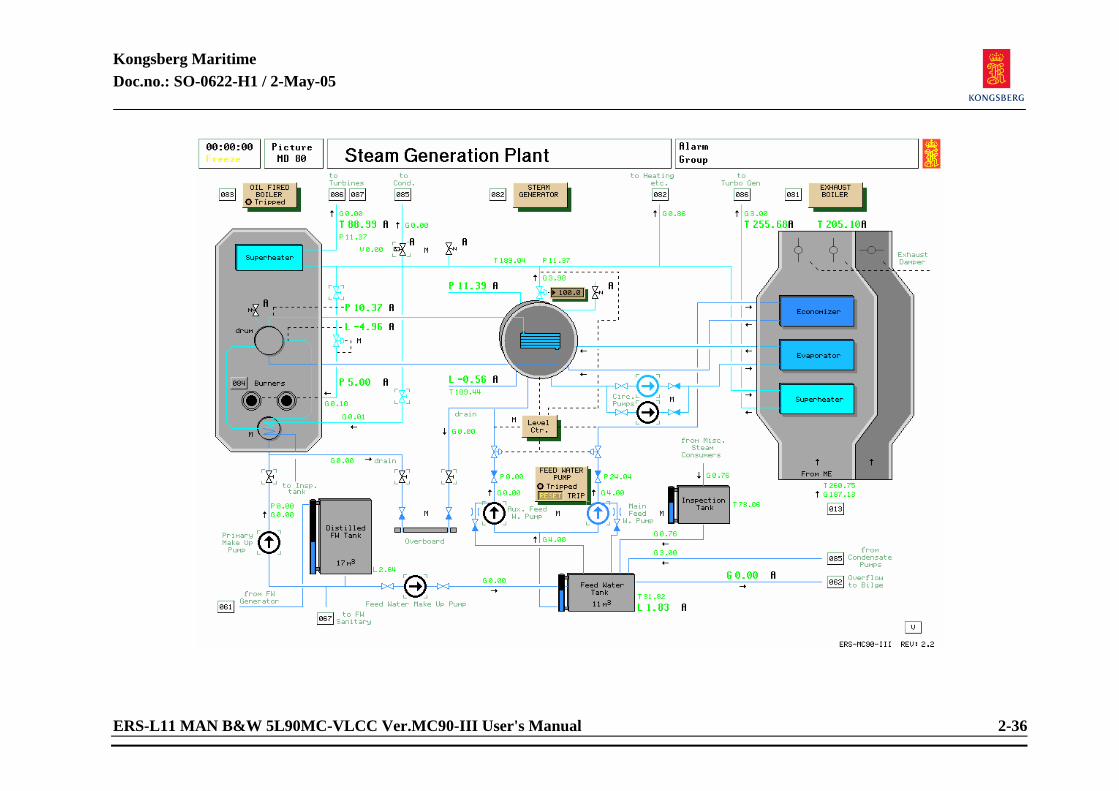
Kongsberg Maritime Doc.no.: SO-0622-H1 / 2-May-05
ERS-L11 MAN B&W 5L90MC-VLCC Ver.MC90-III User's Manual 2-36
Kongsberg Maritime Doc.no.: SO-0622-H1 / 2-May-05
ERS-L11 MAN B&W 5L90MC-VLCC Ver.MC90-III User's Manual 2-37
2.1.9 Steam Generation Plant Related systems required to be in operation:
Main bus bar to be active. Preparations before starting "Steam generation plant":
Select picture Sea Water system and ensure that there is sea water cooling opened to condenser. Flow controller adjusted to a suitable value. Select picture Steam Condenser. Start vacuum pump, and wait until alarm high pressure in condenser is off. Start one condensate pump. Select picture “Steam generation plant”. Ensure sufficient level in Feed Water Tank, if not refill by running feed water pump. Ensure sufficient level in primary drum, if not, run primary make-up pump and open valve after pump. When refilling a cold boiler, water will expand when heated. Do not overfill when boiler is cold. If primary or secondary drum has too high water level, water can be drained to feed water tank by opening drain valve(s). Start feed water pump, RESET if tripped, set level controller to AUTO.
Starting procedure: Start circulation pump to exhaust evaporator. Open steam outlet valve from secondary drum.
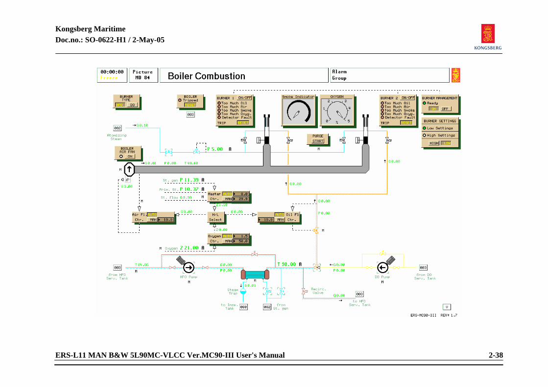
Kongsberg Maritime Doc.no.: SO-0622-H1 / 2-May-05
ERS-L11 MAN B&W 5L90MC-VLCC Ver.MC90-III User's Manual 2-38
Kongsberg Maritime Doc.no.: SO-0622-H1 / 2-May-05
ERS-L11 MAN B&W 5L90MC-VLCC Ver.MC90-III User's Manual 2-39
2.1.10 Boiler Combustion Related systems required to be in operation:
Main bus bar to be active. Sea water cooling system to be active. Air compressor system to be active. Note that there has to be sufficient control air to the operating of boiler fan flap.
Starting procedure:
The Boiler Combustion can also be controlled from the boiler control console. Select picture “Fuel oil service tanks”. Open supply valves from HFO and DO service tanks to boiler. Press Boiler Air Fan ON. Reset any tripping functions on boiler panel and burner panel. All controllers in MANUAL. Burner type on DO. Press purge START, open Air Flow controller to maximum, otherwise purging will not be done. When purging is finished, start DO pump and select DO on three way valve by clicking on diesel line with left tracker-ball button. Set desired values on Air Flow Controller and Oil Flow Controller. (Wait until flap has positioned to set value before starting of burner.) Start one burner by pressing burner ON. If for any number of reasons, burner fails to ignite, purge again and repeat procedure. Adjust air and oil to obtain burning with as little smoke as possible, and as little oxygen content as possible. When you have steam pressure, commence heating of fuel oil by heating tanks. See service tank instruction.
Kongsberg Maritime Doc.no.: SO-0622-H1 / 2-May-05
ERS-L11 MAN B&W 5L90MC-VLCC Ver.MC90-III User's Manual 2-40
When pressure rises, start second burner and adjust air/oil again. Keeping a boiler within limits when operating manually is a continuous task. When required steam pressure is achieved, switch controllers to AUTO.
Auto mode: When burner controls are switched to AUTO, adjust master controller, air flow controller, and oxygen controller to maintain correct readings.
Changing to heavy fuel oil:
Sufficient preheating of HFO is essential. Start HFO pump. Switch to HFO with three way valve.
Burner Management: Select the load setting that corresponds to mode of operation: “high setting” is required for cargo pump turbine operation, else “low setting”. In high setting the steam pressure will be controlled at 13 bar. The exhaust boiler and the TG are assumed inactive. In low setting the steam pressure will float according to TG load. The oil fired boiler will start if pressure drops less than 8 bar. Ensure that there is steam on steam atomization line. Press burner type to HFO. Set Burner management to AUTO. Burner management will now start and stop burners automatically when required.

Kongsberg Maritime Doc.no.: SO-0622-H1 / 2-May-05
ERS-L11 MAN B&W 5L90MC-VLCC Ver.MC90-III User's Manual 2-41
<This page is intentionally left blank>
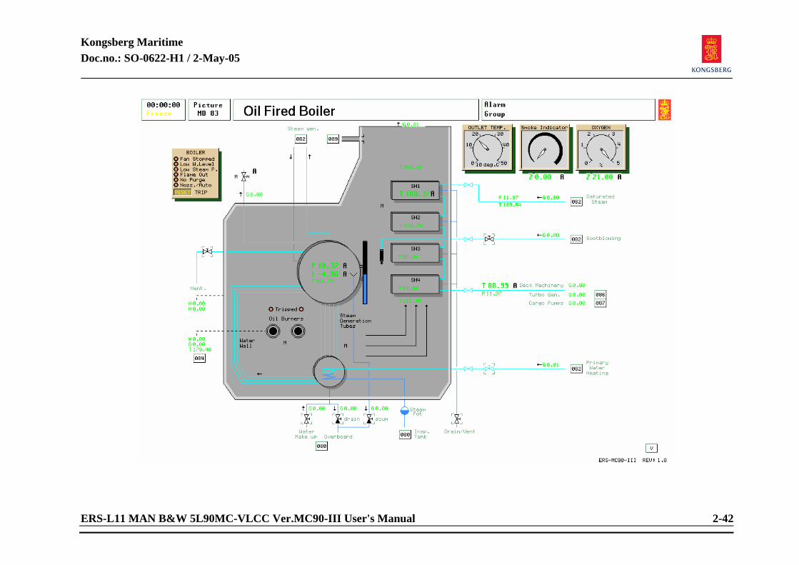
Kongsberg Maritime Doc.no.: SO-0622-H1 / 2-May-05
ERS-L11 MAN B&W 5L90MC-VLCC Ver.MC90-III User's Manual 2-42
Kongsberg Maritime Doc.no.: SO-0622-H1 / 2-May-05
ERS-L11 MAN B&W 5L90MC-VLCC Ver.MC90-III User's Manual 2-43
2.1.11 Oil Fired Boiler Related systems to be in operation:
Main bus bar to be active.
Boiler fan must have sufficient power, since start of fan generates a heavy load. DO tanks and HFO tanks to have sufficient level.
Preparations before start:
The oil fired boiler can be controlled from the boiler control console. See instruction “Steam generation plant” before operating “Steam generator Boiler combustion”.
Starting procedure:
For actual firing of boiler see Boiler Combustion.
Check water level and refill if necessary. Reset any tripping functions if any. Drain superheater until dry saturated steam after boiler start.
Sootblowing:
Once daily when in operation. Ensure that air is opened before sootblowing.
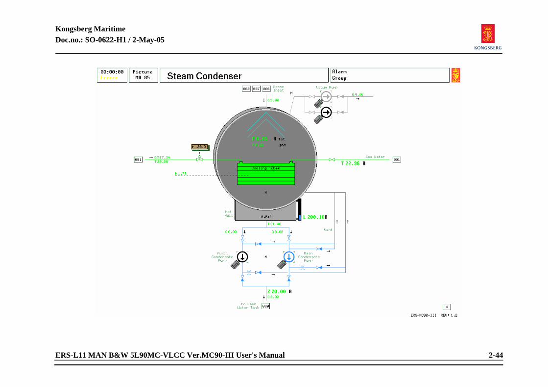
Kongsberg Maritime Doc.no.: SO-0622-H1 / 2-May-05
ERS-L11 MAN B&W 5L90MC-VLCC Ver.MC90-III User's Manual 2-44
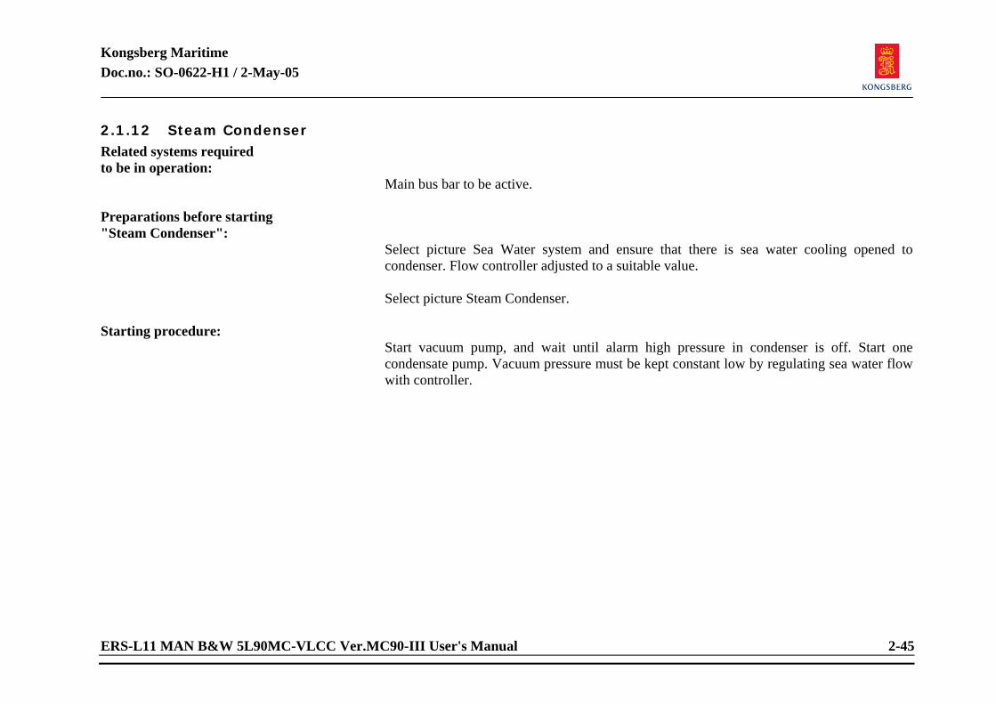
Kongsberg Maritime Doc.no.: SO-0622-H1 / 2-May-05
ERS-L11 MAN B&W 5L90MC-VLCC Ver.MC90-III User's Manual 2-45
2.1.12 Steam Condenser Related systems required to be in operation:
Main bus bar to be active. Preparations before starting "Steam Condenser":
Select picture Sea Water system and ensure that there is sea water cooling opened to condenser. Flow controller adjusted to a suitable value. Select picture Steam Condenser.
Starting procedure:
Start vacuum pump, and wait until alarm high pressure in condenser is off. Start one condensate pump. Vacuum pressure must be kept constant low by regulating sea water flow with controller.
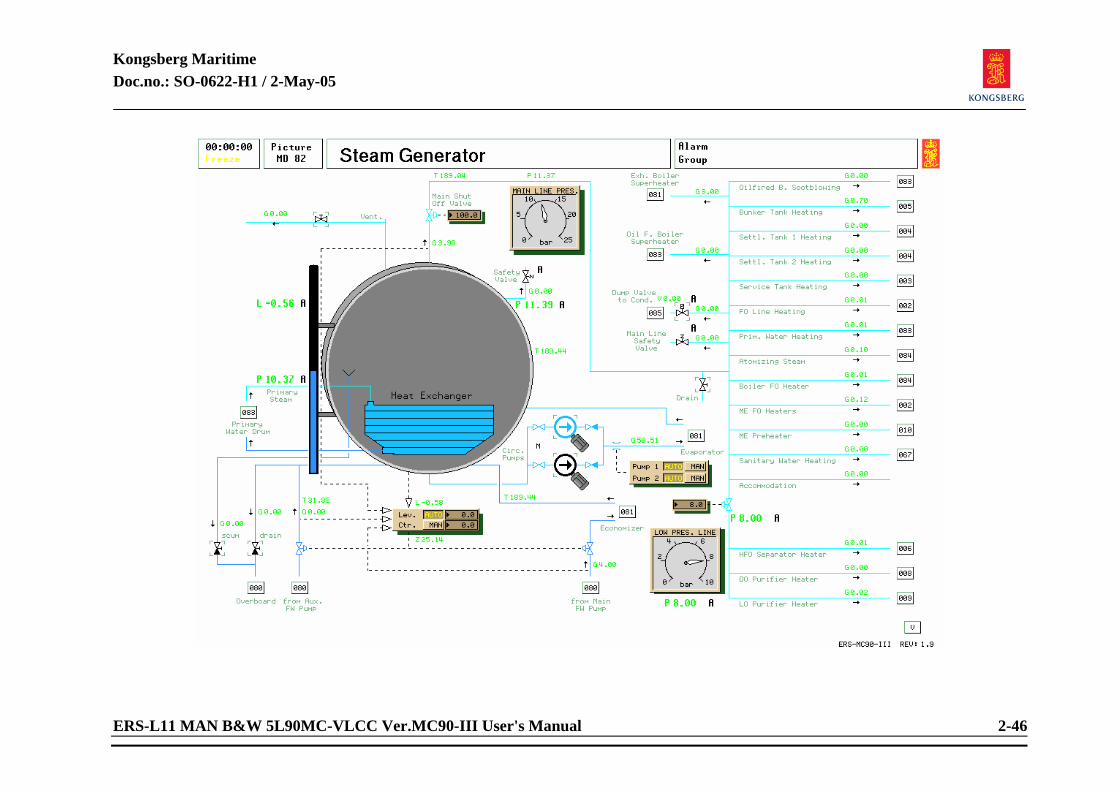
Kongsberg Maritime Doc.no.: SO-0622-H1 / 2-May-05
ERS-L11 MAN B&W 5L90MC-VLCC Ver.MC90-III User's Manual 2-46
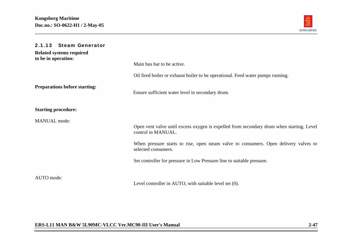
Kongsberg Maritime Doc.no.: SO-0622-H1 / 2-May-05
ERS-L11 MAN B&W 5L90MC-VLCC Ver.MC90-III User's Manual 2-47
2.1.13 Steam Generator Related systems required to be in operation:
Main bus bar to be active. Oil fired boiler or exhaust boiler to be operational. Feed water pumps running.
Preparations before starting:
Ensure sufficient water level in secondary drum. Starting procedure: MANUAL mode:
Open vent valve until excess oxygen is expelled from secondary drum when starting. Level control in MANUAL. When pressure starts to rise, open steam valve to consumers. Open delivery valves to selected consumers. Set controller for pressure in Low Pressure line to suitable pressure.
AUTO mode:
Level controller in AUTO, with suitable level set (0).
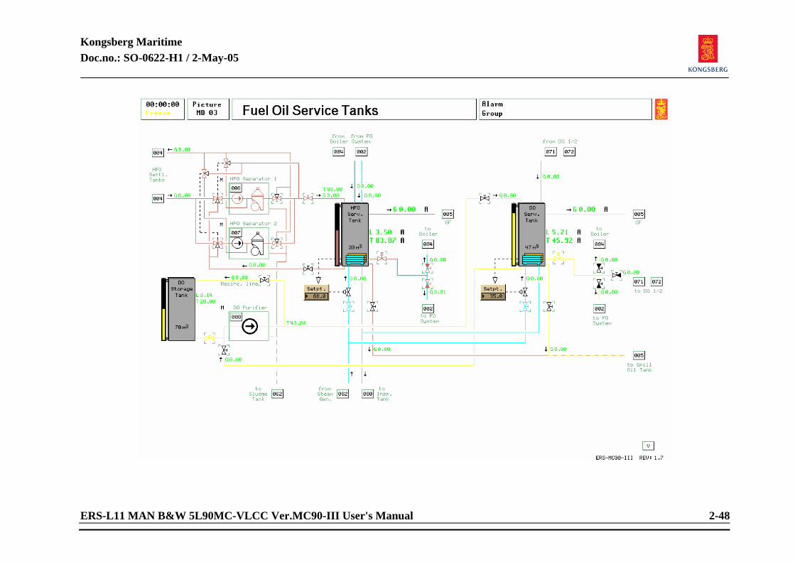
Kongsberg Maritime Doc.no.: SO-0622-H1 / 2-May-05
ERS-L11 MAN B&W 5L90MC-VLCC Ver.MC90-III User's Manual 2-48
Kongsberg Maritime Doc.no.: SO-0622-H1 / 2-May-05
ERS-L11 MAN B&W 5L90MC-VLCC Ver.MC90-III User's Manual 2-49
2.1.14 Fuel Oil Service Tanks Related systems required to be in operation:
Shore Power, Emergency generator or an auxiliary generator connected to the switchboard. Boiler system with sufficient steam pressure.
Preparations before operating "FO Service Tanks":
None Starting procedure: MANUAL mode:
Select picture “FO Service Tanks”. Picture contains HFO service tank, DO service tank and DO storage tank. Filling of each tank with either PURIFIER systems or purifier feed pumps in by-pass. When switching tanks, always open inlet/outlet valves to “new” tanks before closing respectively on “old” tank. To operate purifiers, see separate instructions in this chapter. To use or pump HFO, oil must have sufficient temperature. To obtain heating of tanks: Select picture STEAM GENERATOR MD 82. Open process steam valve. Select picture “FO Service Tanks”. Open steam valves to heating coils in tank bottom. Click with centre button on tracker ball on “SETPOINT” on chosen controller. Adjust setpoint and press enter. As a guide: HFO 65°C and DO 35°C.
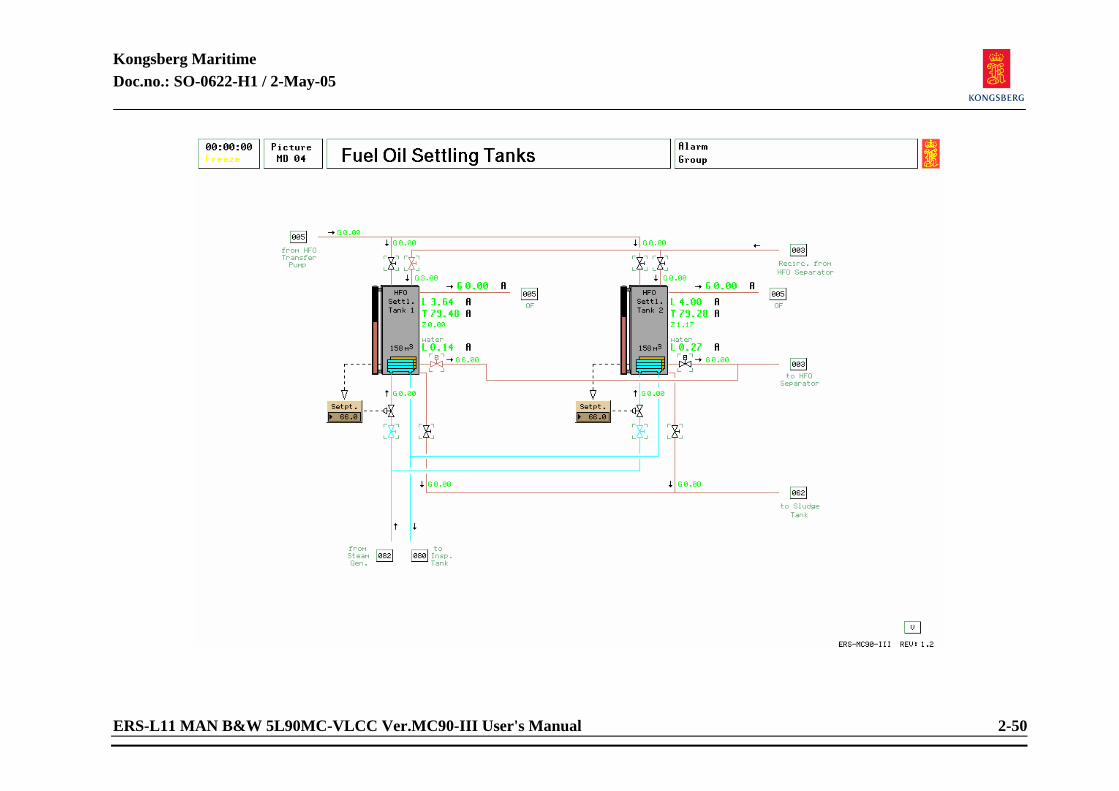
Kongsberg Maritime Doc.no.: SO-0622-H1 / 2-May-05
ERS-L11 MAN B&W 5L90MC-VLCC Ver.MC90-III User's Manual 2-50
Kongsberg Maritime Doc.no.: SO-0622-H1 / 2-May-05
ERS-L11 MAN B&W 5L90MC-VLCC Ver.MC90-III User's Manual 2-51
2.1.15 Fuel Oil Settling Tanks Related systems required to be in operation:
Steam system for heating of oil. Preparations before starting heating:
Sufficient oil level in tanks. Starting procedure: MANUAL mode:
Select one tank to be in service. From this tank open outlet valve to HFO Separator. Open recirculation into tank from HFO Separator. Open heating valves to and from heating coils and set desired temp on controller. HFO requires above 40°C to be pumped. Drain water from tanks periodically, or when alarms activate (at 0.80m). Water content can be read from picture.
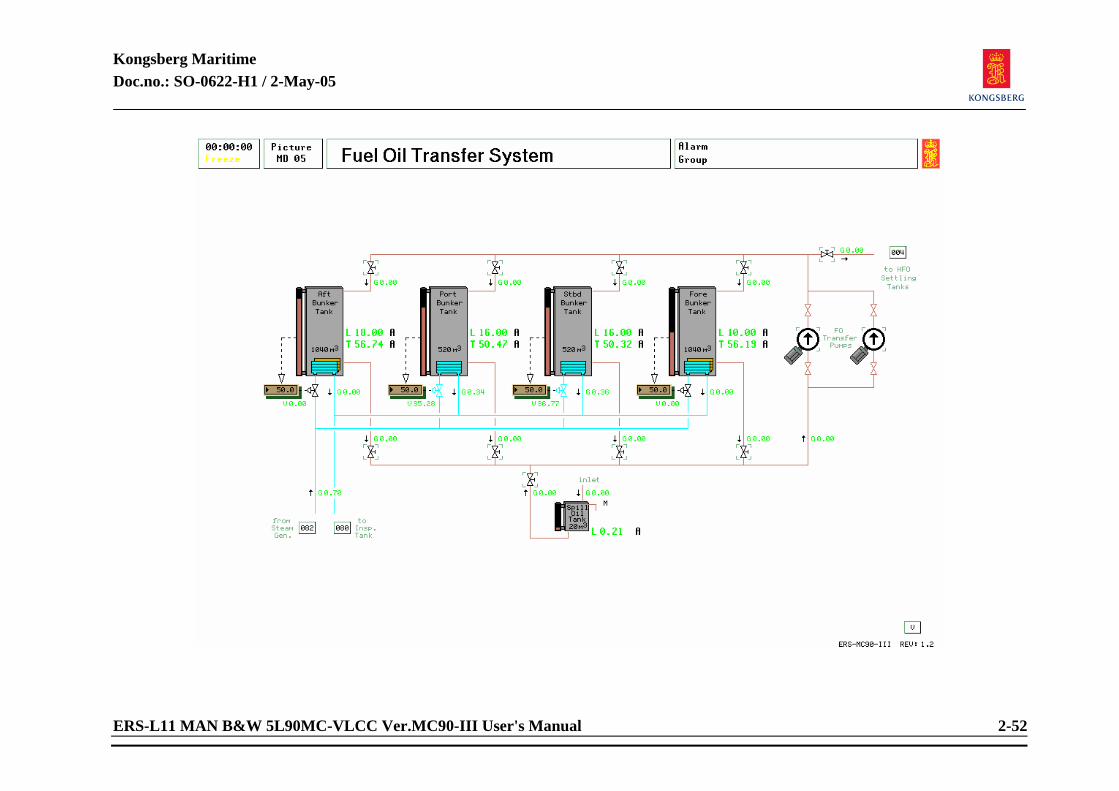
Kongsberg Maritime Doc.no.: SO-0622-H1 / 2-May-05
ERS-L11 MAN B&W 5L90MC-VLCC Ver.MC90-III User's Manual 2-52
Kongsberg Maritime Doc.no.: SO-0622-H1 / 2-May-05
ERS-L11 MAN B&W 5L90MC-VLCC Ver.MC90-III User's Manual 2-53
2.1.16 Fuel Oil Transfer System Related systems required to be in operation:
Main bus bar active. Steam system running. DO/HFO purifier running.
Diesel oil transferring from DO storage tank to DO service tank:
Select picture “Fuel Oil Service Tanks”. Open diesel oil suction valve from DO storage tank to DO purifier. Close diesel oil suction valve from DO service tank to DO purifier. Open diesel oil discharge valve to DO service tank from DO purifier. Close diesel oil discharge valve to DO storage tank from DO purifier. Always open diesel outlet valve on DO storage tank before closing outlet valve on DO service tank. NOTE! Transfer of diesel oil is done with DO purifier on separate instruction. Heating of DO service tank is normally set to 35°C.
Transferring of HFO Related systems required to be in operation:
Main bus bar active. Boiler running with normal steam pressure. HFO Separator running.
Kongsberg Maritime Doc.no.: SO-0622-H1 / 2-May-05
ERS-L11 MAN B&W 5L90MC-VLCC Ver.MC90-III User's Manual 2-54
Heavy fuel oil transferring from HFO settling tanks to HFO service tank:
Select picture “Fuel Oil Settling Tanks”. Open fuel oil outlet valve from HFO settling tank to HFO separator. Select picture “Fuel oil Service Tanks”. Open fuel oil separator suction valve from HFO settling tanks. Close fuel oil separator suction valve from HFO service tank. Open fuel oil discharge valve from separator to HFO service tank. Close fuel oil discharge valve to HFO settling tanks. Always open valves on HFO settling tank before closing valves on HFO service tank.
Heavy fuel oil transferring from bunker tanks to settling tanks:
Select picture “Fuel Oil Settling tanks” Open inlet to selected tank from HFO transfer pump. Open outlet from selected bunker tank. Start transfer pump after opening of outlet valve. Observe that transfer of oil between bunker tanks is possible. Ensure that valves going to bunker tanks are closed when transferring to settling tanks. NOTE! On actual ships, oil is preheated only on bunker tanks in present “use”. Prolonged
heating when oil is not consumed are both waste of energy and also opens possibility for polymerization of oil.
Kongsberg Maritime Doc.no.: SO-0622-H1 / 2-May-05
ERS-L11 MAN B&W 5L90MC-VLCC Ver.MC90-III User's Manual 2-55
<This page is intentionally left blank>
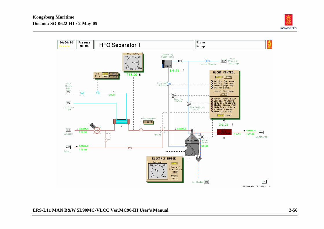
Kongsberg Maritime Doc.no.: SO-0622-H1 / 2-May-05
ERS-L11 MAN B&W 5L90MC-VLCC Ver.MC90-III User's Manual 2-56
Kongsberg Maritime Doc.no.: SO-0622-H1 / 2-May-05
ERS-L11 MAN B&W 5L90MC-VLCC Ver.MC90-III User's Manual 2-57
2.1.17 HFO Purifier System Related systems required to be in operation:
Main bus bar active and Boiler running with normal steam pressure.
Preparation before start:
Open outlet valve from selected HFO settling tank (MD04). Open HFO SEP oil inlet valve to separator (MD03). Open HFO SEP oil outlet valve to HFO service tank (MD03). Open HFO SEP HEATER STEAM shut off valve (MD06). Open valve for displacement water.
Starting procedure: Start HFO SEP feed pump. Adjust desired flow. Set temperature controller to AUTO and adjust setpoint to 98°C. Start electric motor (centrifuge). When the centrifuge speed has stabilized (observe “waiting for speed” indication on ALCAP control panel), put the ALCAP into operation by pressing the start button on the control panel. When correct oil temperature (observe indication on the ALCAP control panel), the three way valve will open for delivery to the separator. Observe flow after separator.
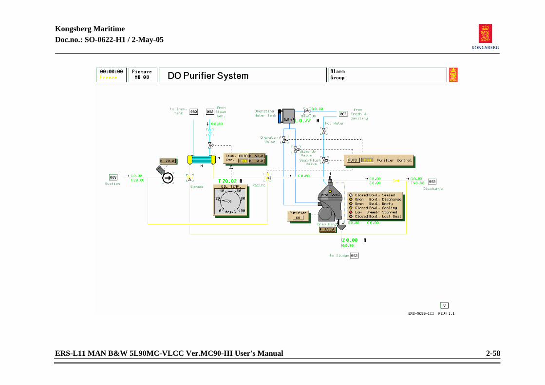
Kongsberg Maritime Doc.no.: SO-0622-H1 / 2-May-05
ERS-L11 MAN B&W 5L90MC-VLCC Ver.MC90-III User's Manual 2-58
Kongsberg Maritime Doc.no.: SO-0622-H1 / 2-May-05
ERS-L11 MAN B&W 5L90MC-VLCC Ver.MC90-III User's Manual 2-59
2.1.18 DO Purifier System Related systems required to be in operation:
Main bus bar active. Boiler running with normal steam pressure.
Preparations before start:
Select Fuel oil service tanks (MD 03). Open outlet valve from selected DO settling tank. Open inlet valve to DO service tanks. Select DO purifier system. Start purifier feed pump. Adjust desired flow. (When starting less than 10 %). Set temp. controller in auto and adjust setpoint to 60°C. Start purifier by pushing purifier button on. Fill operating water tank if necessary.
Starting procedure: MANUAL mode:
After purifier has reached full revolutions, and purifier controller is in manual. Open make-up valve and wait until mimic reads CLOSED BOWL SEALING. Open seal/flush valve for 15 seconds to ensure proper water seal in bowl after mimic reads CLOSED BOWL SEALING.
Kongsberg Maritime Doc.no.: SO-0622-H1 / 2-May-05
ERS-L11 MAN B&W 5L90MC-VLCC Ver.MC90-III User's Manual 2-60
When mimic reads CLOSED BOWL SEALED, open oil flow to purifier by clicking open on three way recirculation valve towards purifier. Oil must have sufficient temperature. Start purifying process with gravity ring less than 20 % of full scale. Adjust gravity ring to maximum value without loosing water seal and adjust oil flow gradually to 100 %.
Ejection cycle:
Close recirculation valve by pointing to valve flange facing purifier and click the close button. (Right tracker-ball button) After lost seal appears, open seal/flush valve for 5 seconds to empty bowl. Close make-up valve. Open operating valve for 5 seconds, mimic reads OPEN BOWL DISHARGE and OPEN BOWL EMPTY. Close operating valve. Wait 15 seconds. Open make-up valve, mimic reads CLOSED BOWL SEALING. When CLOSED BOWL SEALING appears, open seal/flush valve until mimic reads CLOSED BOWL SEALED. When CLOSED BOWL SEALED appears, open recirculation valve towards purifier. All the while operating valves, indicating lamps must be observed to prevent rushing the procedure of Starting Cycle/Ejection Cycle.
AUTO mode:
Preparation as in manual mode. When purifier has reached full speed, push AUTO button on purifier control.
Kongsberg Maritime Doc.no.: SO-0622-H1 / 2-May-05
ERS-L11 MAN B&W 5L90MC-VLCC Ver.MC90-III User's Manual 2-61
Repurification of DO service tank: Select picture “Fuel Oil Service Tanks”. Open fuel oil purifier suction valve from DO service tank. Close fuel oil purifier suction valve from DO settling tanks. Open fuel oil discharge valve from purifier to DO service tank. Close fuel oil discharge valve to DO settling tanks. Always open valves on DO service tank before closing valves on DO settling tanks.

Kongsberg Maritime Doc.no.: SO-0622-H1 / 2-May-05
ERS-L11 MAN B&W 5L90MC-VLCC Ver.MC90-III User's Manual 2-62
Kongsberg Maritime Doc.no.: SO-0622-H1 / 2-May-05
ERS-L11 MAN B&W 5L90MC-VLCC Ver.MC90-III User's Manual 2-63
2.1.19 Lub Oil Purifier System Related systems required to be in operation:
Main bus bar active. Boiler running with normal steam pressure.
Preparations before start:
Select one of main engine lub. oil systems. Open outlet valve from selected lub. oil drain tank. Open inlet valve to selected lub. oil drain tank. Select LO purifier system. Start purifier feed pump. Adjust desired flow. (Less than 10 % when starting). Set temp. controller in auto and adjust setpoint to 86°C. Start purifier by pushing purifier button on. Fill operating water tank if necessary.
Starting procedure: MANUAL mode:
After purifier has reached full revolutions, and purifier controller is in manual, open make-up valve and wait until mimic reads CLOSED BOWL SEALING. Open seal/flush valve for 15 seconds to ensure proper water seal in bowl after mimic reads CLOSED BOWL SEALING.
Kongsberg Maritime Doc.no.: SO-0622-H1 / 2-May-05
ERS-L11 MAN B&W 5L90MC-VLCC Ver.MC90-III User's Manual 2-64
When mimic reads CLOSED BOWL SEALED, open oil flow to purifier by clicking open on three way recirculation valve towards purifier. Oil must have sufficient temperature. Start purifying process with gravity ring less than 20% of full scale. Adjust gravity ring to maximum value without loosing water seal and adjust oil flow gradually to 100%.
Ejection cycle:
Close recirculation valve by pointing to valve flange facing purifier and click the close button. (Right tracker-ball button) After lost seal appears, open seal/flush valve for 5 seconds to empty bowl. Close make-up valve. Open operating valve for 5 seconds, mimic reads OPEN BOWL DISHARGE and OPEN BOWL EMPTY. Close operating valve. Wait 15 seconds. Open-make-up valve, mimic reads CLOSED BOWL SEALING. When indicator reads CLOSED BOWL SEALING, open seal/flush valve until mimic reads CLOSED BOWL SEALED. When CLOSED BOWL SEALED appears, open recirculation valve towards purifier. All the while operating valves, indicating lamps must be observed to prevent rushing the procedure of Starting Cycle/Ejection Cycle.
AUTO mode:
Preparation as in manual mode.
When purifier has reached full speed, push AUTO button on purifier control.

Kongsberg Maritime Doc.no.: SO-0622-H1 / 2-May-05
ERS-L11 MAN B&W 5L90MC-VLCC Ver.MC90-III User's Manual 2-65
<This page is intentionally left blank>
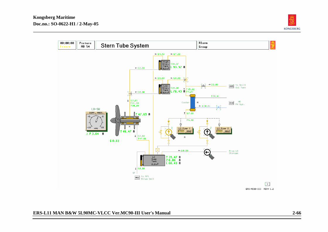
Kongsberg Maritime Doc.no.: SO-0622-H1 / 2-May-05
ERS-L11 MAN B&W 5L90MC-VLCC Ver.MC90-III User's Manual 2-66
Kongsberg Maritime Doc.no.: SO-0622-H1 / 2-May-05
ERS-L11 MAN B&W 5L90MC-VLCC Ver.MC90-III User's Manual 2-67
2.1.20 Stern Tube System Related systems required to be in operation:
Main bus bar to be active. Low temp fresh water cooling system to be active.
Preparations before starting: Ensure that LTFW system is opened to LO cooler. Refill circulation tank (sump tank) when needed by running make-up pump. Upper or Lower gravity tank must be selected depending on ship draught. Selection of tank based upon differential pressure between sea water (outside ship) and LO pressure. Remember to change both inlet and outlet three way valves.
Starting procedure: MANUAL mode:
Start one LO pump in MANUAL mode. AUTO mode:
After first pump is started, select other pump AUTO mode. The stand-by pump will start automatically if the running pump is not able to maintain the level in the gravity tank. Stopping of pump to be carried out manually.
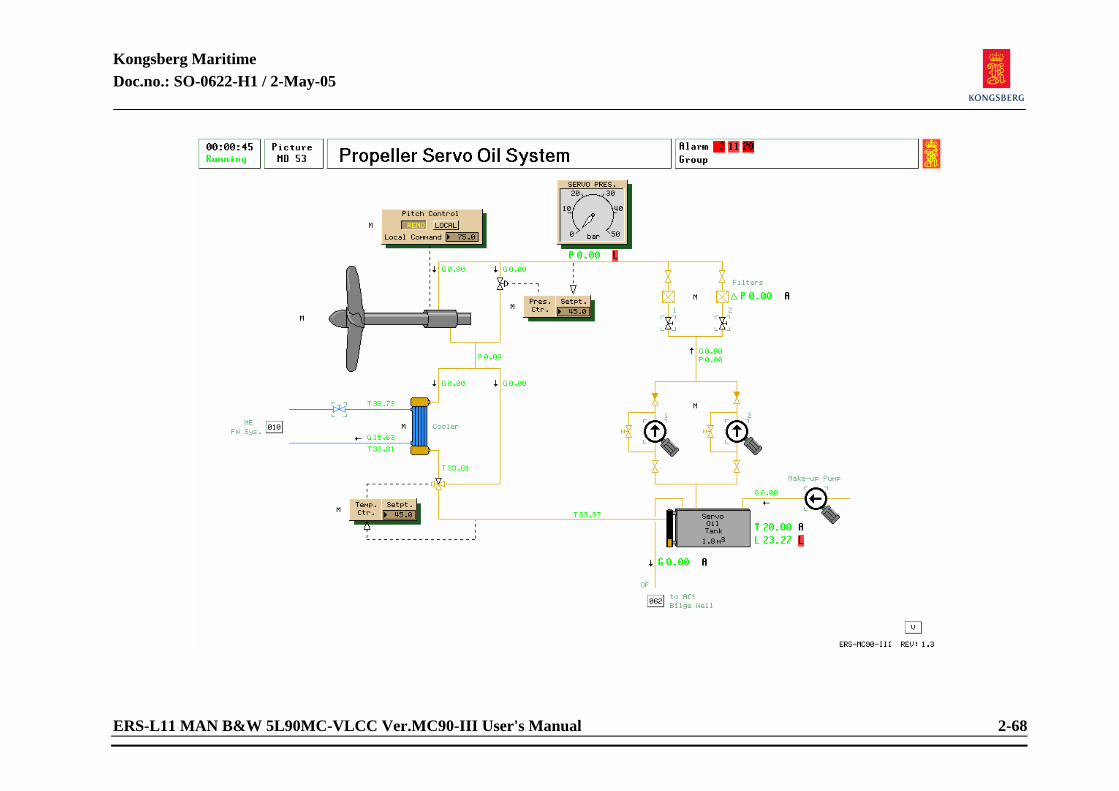
Kongsberg Maritime Doc.no.: SO-0622-H1 / 2-May-05
ERS-L11 MAN B&W 5L90MC-VLCC Ver.MC90-III User's Manual 2-68
Kongsberg Maritime Doc.no.: SO-0622-H1 / 2-May-05
ERS-L11 MAN B&W 5L90MC-VLCC Ver.MC90-III User's Manual 2-69
2.1.21 Propeller Servo LO System Related systems required to be in operation:
Main bus bar active. LTFW cooling system.
Preparation before start: Open valve before one LO filter. Ensure sufficient cooling water to cooler, and that valve is opened. Setting of temp controller to 45°C. Setting of pressure controller to wanted pressure. (45 bar). Refill Servo Oil Tank if needed by running make-up pump.
Starting procedure: MANUAL mode:
Pitch control in LOCAL. Start one servo oil pump.
AUTO mode: Select power chief pump control. After starting one pump, push AUTO button. Set pitch controller in REMOTE. NOTE! Most AutoChief plants (main engine remote controls) do not permit engine to be
started unless pitch is in zero position. NOTE! PowerChief: Propeller servo auto visible only if CPP mode is selected.
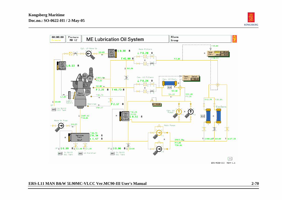
Kongsberg Maritime Doc.no.: SO-0622-H1 / 2-May-05
ERS-L11 MAN B&W 5L90MC-VLCC Ver.MC90-III User's Manual 2-70
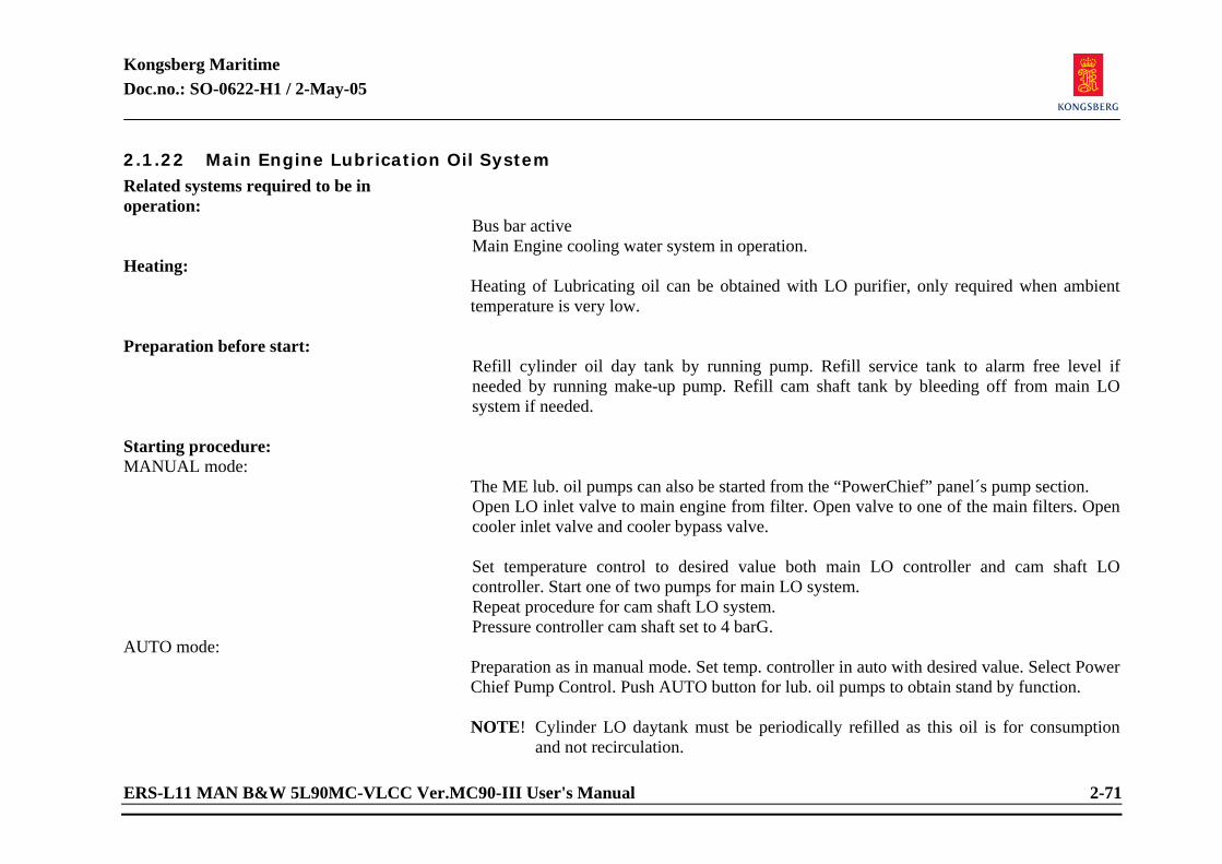
Kongsberg Maritime Doc.no.: SO-0622-H1 / 2-May-05
ERS-L11 MAN B&W 5L90MC-VLCC Ver.MC90-III User's Manual 2-71
2.1.22 Main Engine Lubrication Oil System Related systems required to be in operation:
Bus bar active Main Engine cooling water system in operation.
Heating: Heating of Lubricating oil can be obtained with LO purifier, only required when ambient temperature is very low.
Preparation before start:
Refill cylinder oil day tank by running pump. Refill service tank to alarm free level if needed by running make-up pump. Refill cam shaft tank by bleeding off from main LO system if needed.
Starting procedure: MANUAL mode:
The ME lub. oil pumps can also be started from the “PowerChief” panel´s pump section. Open LO inlet valve to main engine from filter. Open valve to one of the main filters. Open cooler inlet valve and cooler bypass valve. Set temperature control to desired value both main LO controller and cam shaft LO controller. Start one of two pumps for main LO system. Repeat procedure for cam shaft LO system. Pressure controller cam shaft set to 4 barG.
AUTO mode: Preparation as in manual mode. Set temp. controller in auto with desired value. Select Power Chief Pump Control. Push AUTO button for lub. oil pumps to obtain stand by function.
NOTE! Cylinder LO daytank must be periodically refilled as this oil is for consumption
and not recirculation.
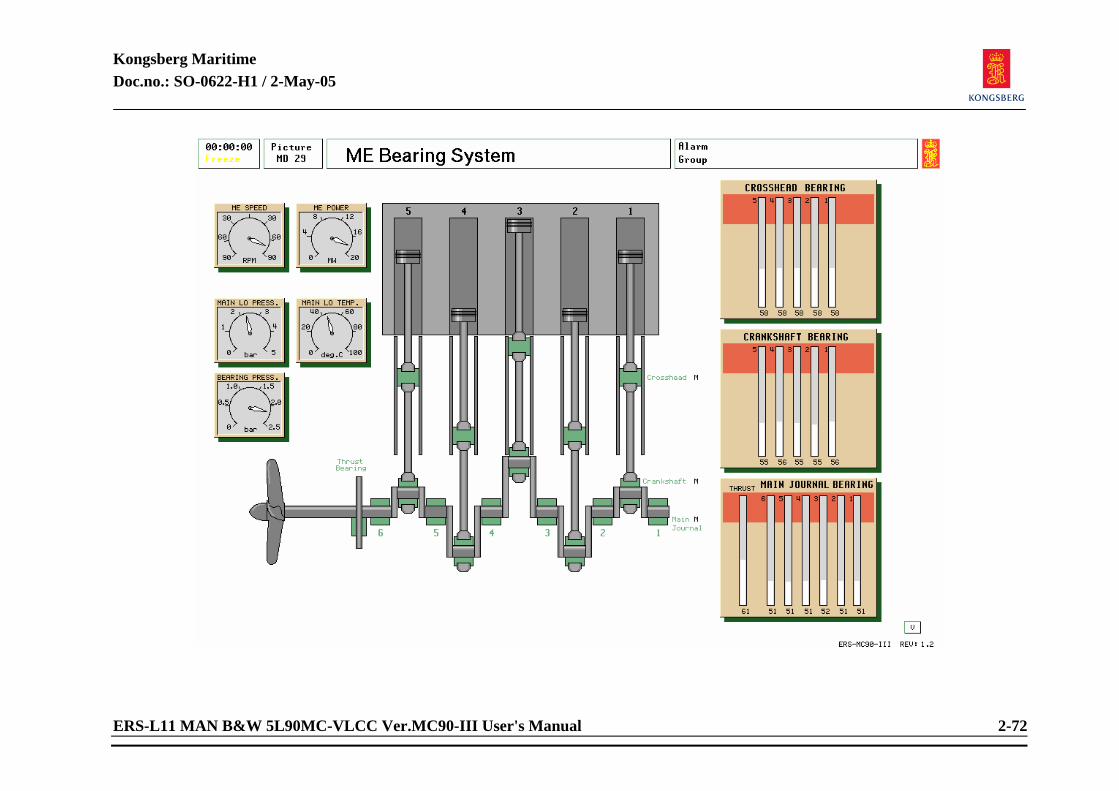
Kongsberg Maritime Doc.no.: SO-0622-H1 / 2-May-05
ERS-L11 MAN B&W 5L90MC-VLCC Ver.MC90-III User's Manual 2-72
Kongsberg Maritime Doc.no.: SO-0622-H1 / 2-May-05
ERS-L11 MAN B&W 5L90MC-VLCC Ver.MC90-III User's Manual 2-73
2.1.23 Main Engine Bearing System Related systems required to be in operation:
Bus bar active. Main Engine running. Read only. Used for readout of LO pressures and temperatures while main engine is running. Thrust bearing LO pressure readout. Main engine speed and power readout.
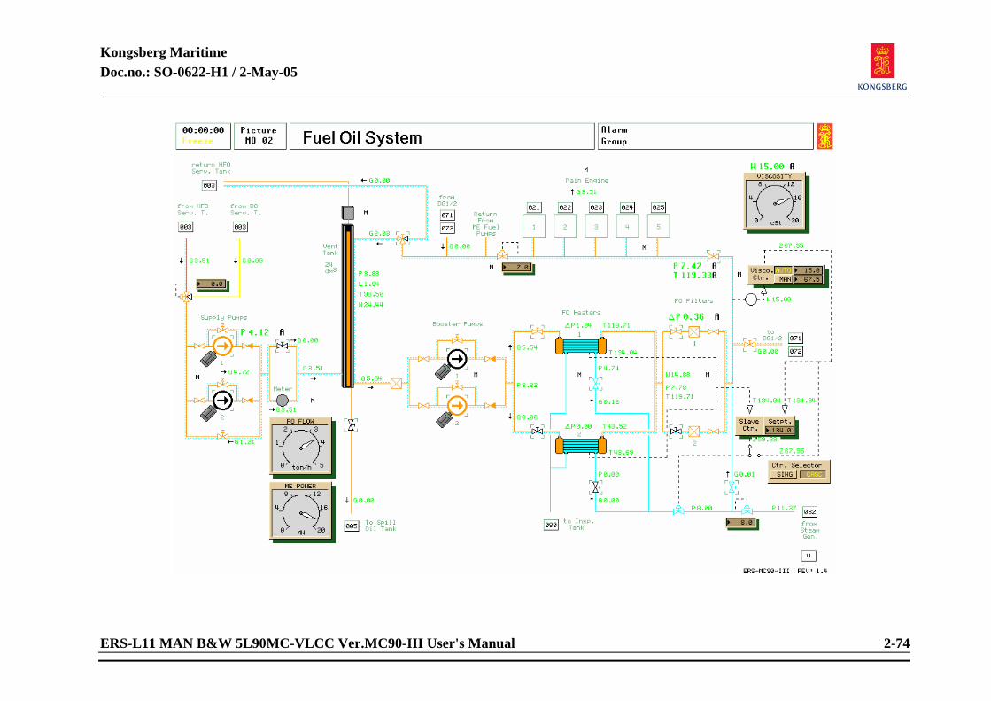
Kongsberg Maritime Doc.no.: SO-0622-H1 / 2-May-05
ERS-L11 MAN B&W 5L90MC-VLCC Ver.MC90-III User's Manual 2-74
Kongsberg Maritime Doc.no.: SO-0622-H1 / 2-May-05
ERS-L11 MAN B&W 5L90MC-VLCC Ver.MC90-III User's Manual 2-75
2.1.24 Main Engine Fuel Oil System Related systems required to be in operation:
Bus bar active.
Heating: Steam pressure for heating when using HFO. Oil can be circulated by opening three way valve return to service tank.
Preparation before start:
Select diesel oil operation on three way mixing valve. Click on window with centre tracker-ball button and enter 100% for pure diesel oil and 0% for pure heavy fuel oil operation. Make sure that valves are opened and oil is flowing to booster pumps from HFO and DO service tanks.
Starting procedure: MANUAL mode:
The ME fuel oil pumps can also be started from the “PowerChief” panel’s pump section. Close bypass valve on fuel oil flow meter. Close drain valve from ventilation tank. Open valves into one of FO heaters. Open valve to one filter. Open valve to main engine high pressure fuel pumps.
Kongsberg Maritime Doc.no.: SO-0622-H1 / 2-May-05
ERS-L11 MAN B&W 5L90MC-VLCC Ver.MC90-III User's Manual 2-76
Viscosity controller in MANUAL: Fuel oil back pressure controller set to less than 10 barG. (Above 10 barG prevents recirculation of oil in fuel injectors since they close above 12 barG.) Three way return valve set with return to ventilation tank. Click open on desired flow direction with left tracker-ball button. Start one fuel oil booster pump.
AUTO mode:
Select Power Chief pump control panel and set pumps in AUTO. Select AUTO on viscosity controller panel.
NOTE! Viscosity controller can be varied from SINGLE to CASCADE mode. Varying
flow/temperature conditions may need different settings. When using CASCADE control, remember to set slave controller setpoint to less temperature than viscosity settings would reflect. Depending largely on viscosity index chart, consult this for setting with emphasis on actual oil quality.
Changing to heavy fuel oil:
Open steam valves to FO heaters. Open steam valve to steam tracing lines. Steam line pressure controller to desired setting. (8 barG) Ensure steam consumer valve is opened. Gradually change value in three way mixing valve to pure HFO. Quicker change-over can be obtained with return to service tank opened. This, however, may cause needle valves to stick in fuel injectors.
Changing from HFO to DO: Lower temperature on HFO by setting on viscosity controller. When temperature drops, gradually mix in diesel oil. All the while observing that change-over is not too rapid. This can also cause needles in fuel injectors to stick.

Kongsberg Maritime Doc.no.: SO-0622-H1 / 2-May-05
ERS-L11 MAN B&W 5L90MC-VLCC Ver.MC90-III User's Manual 2-77
<This page is intentionally left blank>
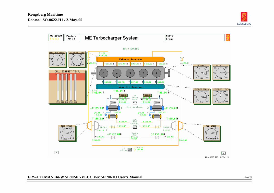
Kongsberg Maritime Doc.no.: SO-0622-H1 / 2-May-05
ERS-L11 MAN B&W 5L90MC-VLCC Ver.MC90-III User's Manual 2-78
Kongsberg Maritime Doc.no.: SO-0622-H1 / 2-May-05
ERS-L11 MAN B&W 5L90MC-VLCC Ver.MC90-III User's Manual 2-79
2.1.25 Main Engine Turbocharger System Related systems required to be in operation:
LTFW cooling system Starting procedure:
Valves from exhaust gas receiver to turbo-chargers must be opened before attempting to start engine, or when blowing through with starting air prior to start.
MANUAL mode:
Open LTFW to air coolers, with low setting of flow. While running engine, care must be taken not to cool air below dew point in order to avoid water droplets in scavenging air resulting in high cylinder wear. (Sulphuric corrosion and loss of cylinder lubrication.) Check that Slide valve controller is set to MANUAL. (Variable page 1301) Open slide valves. Close Waste Heat Recovery valves.
AUTO mode: After start of engine, set Slide Valve Controller to AUTO. (Variable page 1301) The slide valves will open/close depending on exhaust gas flow. NOTE! When running full power on main engine, fuel tanks can be heated by Waste Heat
Recovery system. Open valves and consult Waste Heat Recovery picture (MD 65) for operation.
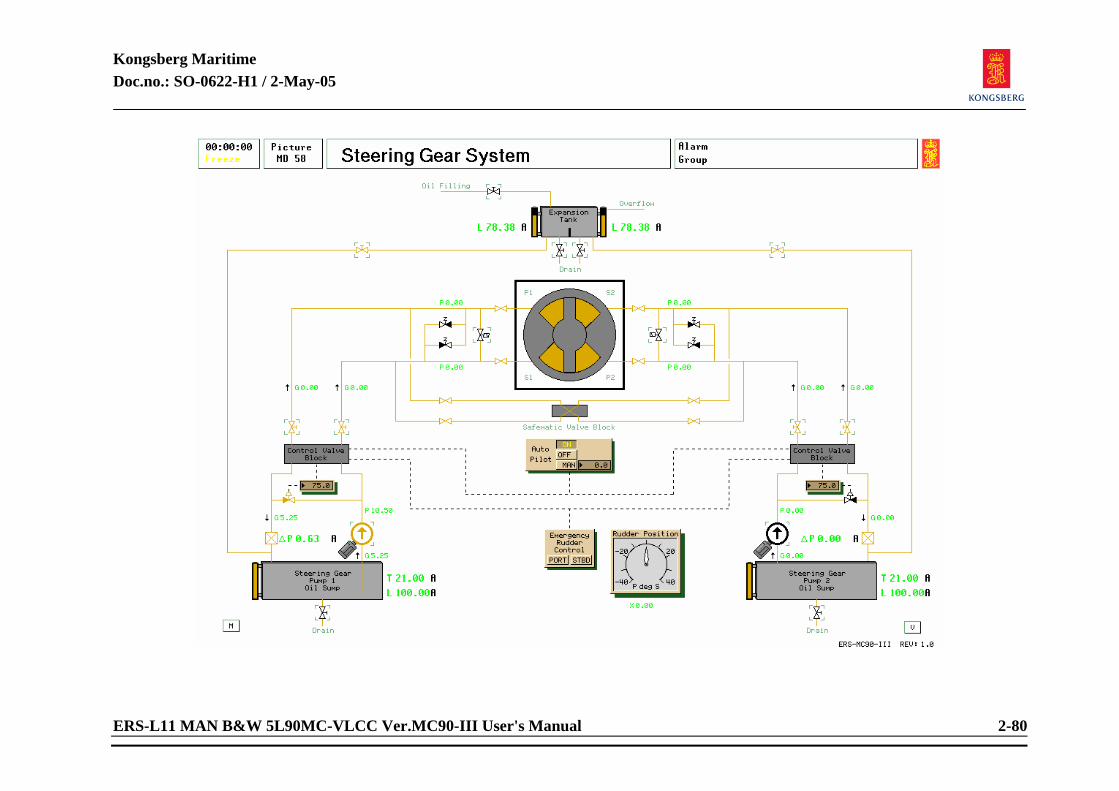
Kongsberg Maritime Doc.no.: SO-0622-H1 / 2-May-05
ERS-L11 MAN B&W 5L90MC-VLCC Ver.MC90-III User's Manual 2-80
Kongsberg Maritime Doc.no.: SO-0622-H1 / 2-May-05
ERS-L11 MAN B&W 5L90MC-VLCC Ver.MC90-III User's Manual 2-81
2.1.26 Steering Gear System Related systems required to be in operation:
Bus bar active.
Preparation before start:
Check content in hydraulic oil tanks, refill if necessary. Check that steering gear shut off valves are open. Check that Safematic valve block valve is open (position is change from VP5812)
Start procedure:
Start steering gear pump(s) locally (by point and click on pump symbol) or remotely from conrol room or bridge (by pressing the buttons).. Testing of steering gear should be carried out before leaving port. This is normally carried out from the bridge. Emergency steering to be carried out by pressing the port/stbd buttons, remotely from bridge or locally by manually control the control valve block position.
Note that if a failure of automatic control of by-pass and safematic valves should occur, these valves have to be operated locally and by hand.
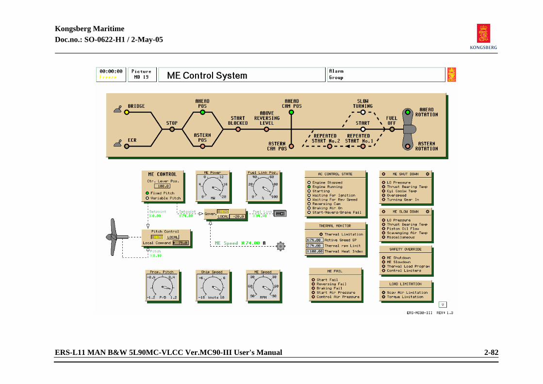
Kongsberg Maritime Doc.no.: SO-0622-H1 / 2-May-05
ERS-L11 MAN B&W 5L90MC-VLCC Ver.MC90-III User's Manual 2-82
Kongsberg Maritime Doc.no.: SO-0622-H1 / 2-May-05
ERS-L11 MAN B&W 5L90MC-VLCC Ver.MC90-III User's Manual 2-83
2.1.27 Main Engine Control System Related systems required to be in operation:
Bus bar active. Main Engine running with subsystems operational. Pitch Control system active. Steering gear system active. Sufficient starting air pressure and control air pressure.
Heating:
Heating of Lubricating oil can be obtained with LO purifier, only required when ambient temperature is very low. Heating of main engine can be done with steam heater. (Water side) If on HFO, oil must be of correct viscosity.
Kongsberg Maritime Doc.no.: SO-0622-H1 / 2-May-05
ERS-L11 MAN B&W 5L90MC-VLCC Ver.MC90-III User's Manual 2-84
Preparation before start: Starting procedure: Check if subsystems are operational. MANUAL mode:
Choose between FIXED PITCH or COMBINATOR CONTROL. Governor Control in LOCAL. Pitch Control in LOCAL. (Only to selected in combinator control.) Control lever can be set from this position, operation from AutoChief panel suggested.
AUTO mode:
Governor control in REMOTE. Pitch control in REMOTE. Run the ME from MD104 or MD105. NOTE! The control lever position is reading of the position of the lever in “AutoChief
Main Engin Control” MD04.

Kongsberg Maritime Doc.no.: SO-0622-H1 / 2-May-05
ERS-L11 MAN B&W 5L90MC-VLCC Ver.MC90-III User's Manual 2-85
<This page is intentionally left blank>
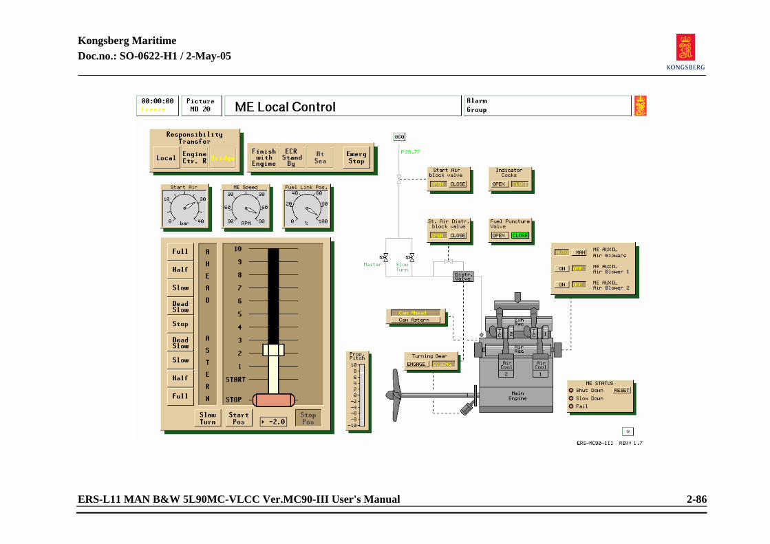
Kongsberg Maritime Doc.no.: SO-0622-H1 / 2-May-05
ERS-L11 MAN B&W 5L90MC-VLCC Ver.MC90-III User's Manual 2-86
Kongsberg Maritime Doc.no.: SO-0622-H1 / 2-May-05
ERS-L11 MAN B&W 5L90MC-VLCC Ver.MC90-III User's Manual 2-87
2.1.28 ME Local Control Related systems required to be in operation: Main bus bar to be active.
Main engine subsystems to be operational. Main engine to be READY with correct temperatures and alarm free condition.
Starting procedure main engine: NOTE! Before starting engine after prolonged stop, always “blow through” engine with
starting air with indicator cocks open. When stoppage exceeds 30 minutes while manoeuvring, it is recommended to perform a Slow Turning of engine before starting attempt is commenced. Slow turning is carried out by pressing the slow turning button. Observe that slow turning valve opens and that ME rotates slowly.
MANUAL mode: Turning gear OUT. Select cam position Fuel Puncture Valve OPEN. This valve will automatically close when lever is passing start and gives fuel index. Indicator cocks CLOSED. Main engine auxiliary blowers MANUAL. Main engine auxiliary blowers both ON. Open Start air block valve. Open start air distr. block valve. Autochief will determine when to close after a starting attempt. Set lever to start position by pressing the button START POS. When ME rotates on start air, type in lever position.
AUTO mode: Main engine auxiliary blowers AUTO. This position suggested at all times when manoeuvring is expected, or when engine is running steady. From Ahead to Astern and vice verca: Press stop position button, change cam position, press start button and type in handle command in numeric window. Note the “above reversing level” before supplying brake air. If Wrong Way alarm is activated, the camshaft direction does not correspond with command from bridge.
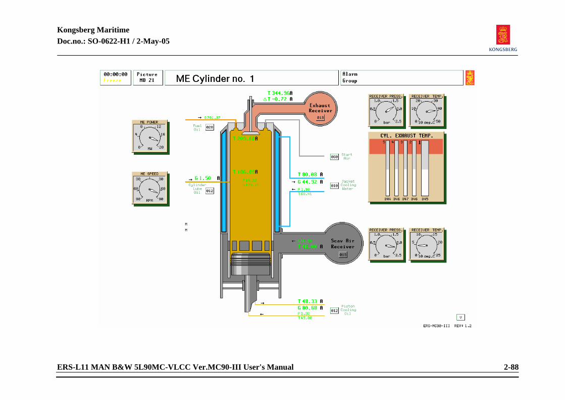
Kongsberg Maritime Doc.no.: SO-0622-H1 / 2-May-05
ERS-L11 MAN B&W 5L90MC-VLCC Ver.MC90-III User's Manual 2-88
Kongsberg Maritime Doc.no.: SO-0622-H1 / 2-May-05
ERS-L11 MAN B&W 5L90MC-VLCC Ver.MC90-III User's Manual 2-89
2.1.29 Main Engine Cylinder No 1-5 Related systems required to be in operation:
N/A. Read only of engine running parameters.
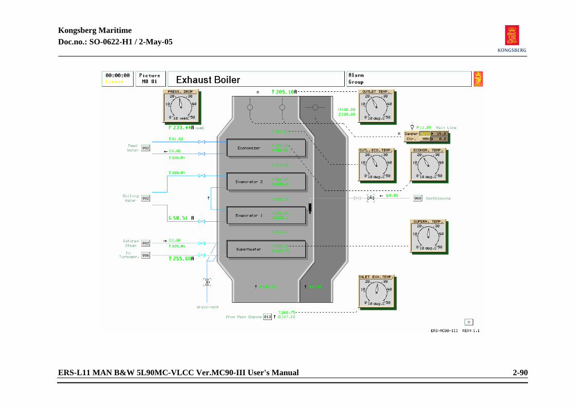
Kongsberg Maritime Doc.no.: SO-0622-H1 / 2-May-05
ERS-L11 MAN B&W 5L90MC-VLCC Ver.MC90-III User's Manual 2-90
Kongsberg Maritime Doc.no.: SO-0622-H1 / 2-May-05
ERS-L11 MAN B&W 5L90MC-VLCC Ver.MC90-III User's Manual 2-91
2.1.30 Exhaust Boiler Related systems required to be in operation:
Main engine to be running. Oil fired boiler to be operating.
Heating:
Running of circulating pumps with oil fired boiler running. Preparation before start:
Drain of water in superheater before opening steam pressure. Starting procedure: MANUAL mode:
Damper control in MANUAL, with by pass positioned open. When main engine is running and oil fired boiler to be stopped. Gradually open damper flap valves to exhaust boiler.
AUTO mode: When Oil fired boiler stops (in AUTO ), and pressure increases in secondary drum steam pressure, switch damper controller to AUTO, stop boiler fan and FO supply pump. Note, that the fan and FO pump will start automatically at decreased ME power (if burner management is active).
NOTE! When in operation, daily sootblowing of smoke uptake must be done. Ensure air
valves are opened before attempting to soot blow. Bleed off water from superheater until dry saturated steam is the only content in superheater.
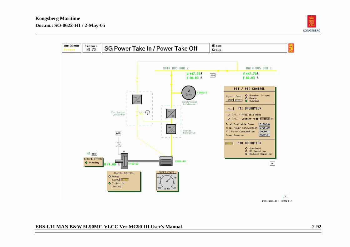
Kongsberg Maritime Doc.no.: SO-0622-H1 / 2-May-05
ERS-L11 MAN B&W 5L90MC-VLCC Ver.MC90-III User's Manual 2-92
Kongsberg Maritime Doc.no.: SO-0622-H1 / 2-May-05
ERS-L11 MAN B&W 5L90MC-VLCC Ver.MC90-III User's Manual 2-93
2.1.31 Shaft Generator/Motor PTO operation: Related systems required to be in operation:
Power available on bus bar 1. Main Engine running.
Preparation before start: Connect bus bar 2 to bus bar 1 (MD70). Open for control air to clutch (MD73).
Starting procedure: Manual:
Set clutch control to LOCAL on Clutch Control Panel (MD73). Connect clutch (press button IN/OUT). NOTE! When ME speed is more than 45% (34 rpm), the PTI/PTO panel will indicate
“READY”. If less than 30 rpm, “ME Speed Low” will be lit. Press Synch. Cond. start button (MD73). Select SG on the SEMI AUTO SYNCH. panel. When ready lamp on the panel is lit, the SG is ready for connection. NOTE! It may be necessary to adjust voltage and frequency to achieve the ready signal. Connect SG to bus bar by pressing the CONN. button. on the SEMI AUTO SYNCH. panel.
Kongsberg Maritime Doc.no.: SO-0622-H1 / 2-May-05
ERS-L11 MAN B&W 5L90MC-VLCC Ver.MC90-III User's Manual 2-94
NOTE! Since the Connect conditions are more restrictive than the Ready conditions, it may be necessary to adjust voltage and frequency even more before the SEMI AUTO connection is carried out.
AUTO:
Set clutch to remote control on the Clutch Control Panel (MD73). Observe that READY lamp on PowerChief panel is lit (MD101). Set SG to AUTO on PowerChief panel (MD101). Set priority.
PTI Operation: Preparation before start:
As for PTO operation.
Start procedure: Local start:
Set clutch control to Local on the Clutch Control Panel MD (73). Connect clutch by pressing the IN/OUT button. Observe that Ready lamp is lit. Select PTI operation by pressing PTI button. Connect the Shaft Motor to the main bus bar by pressing the START button on the PTI/PTO panel. NOTE Setting Mode is the default mode for the PTI operation. If available power
operation is required, press Available Mode button. In this mode the Shaft Motor will take all the available power up to a certain power margin which is set to 50 kW.
Kongsberg Maritime Doc.no.: SO-0622-H1 / 2-May-05
ERS-L11 MAN B&W 5L90MC-VLCC Ver.MC90-III User's Manual 2-95
Start from PowerChief: Set clutch control to REMOTE on the Clutch Control Panel. Press PTI button on the PowerChief Panel (MD101). Press CONNECT on the PowerChief Panel.
Stop of PTI/PTO operation: From PTI/PTO control panel:
Press Synch. Cond. STOP button.
From PowerChief: Press DISCONNECT button. NOTE! In PTO operation the SG will unload before disconnection.
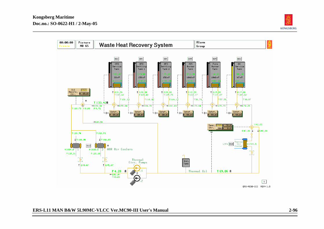
Kongsberg Maritime Doc.no.: SO-0622-H1 / 2-May-05
ERS-L11 MAN B&W 5L90MC-VLCC Ver.MC90-III User's Manual 2-96
Kongsberg Maritime Doc.no.: SO-0622-H1 / 2-May-05
ERS-L11 MAN B&W 5L90MC-VLCC Ver.MC90-III User's Manual 2-97
2.1.32 Waste Heat Recovery System Related systems required to be in operation:
Main bus bar to be active. Main engine running.
Preparation before start:
Main engine must have reached a load where sufficient temperature on turbo-charger is available.
Starting procedure:
Select picture ME Turbo-charger System and open valves for thermal oil on waste heat exchangers. Select FW system and open for cooling water to thermal oil cooler. Start one of two circulating pumps. When oil has reached sufficient temperature, controller will open for thermal oil to fuel tanks by the recirulation three way valve. Set desired temperature on the heating elements and the thermal oil cooler.
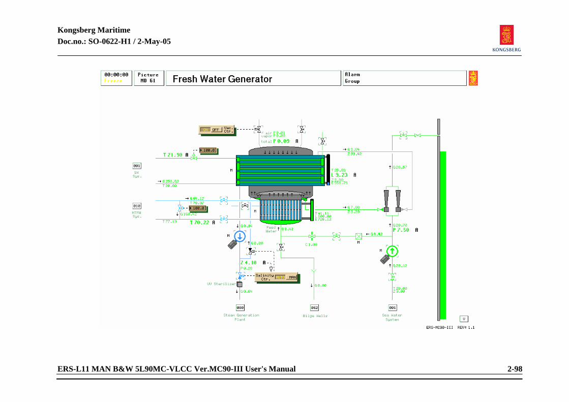
Kongsberg Maritime Doc.no.: SO-0622-H1 / 2-May-05
ERS-L11 MAN B&W 5L90MC-VLCC Ver.MC90-III User's Manual 2-98
Kongsberg Maritime Doc.no.: SO-0622-H1 / 2-May-05
ERS-L11 MAN B&W 5L90MC-VLCC Ver.MC90-III User's Manual 2-99
2.1.33 Fresh Water Generator Related systems required to be in operation:
Main engine running. Operation as an isolated system, see page 6107 on the variable list.
Preparations before starting the "Fresh Water Generator":
Select picture “Fresh Water Generator”. Set load controller to OFF. Set salinity controller to MAN. Set sea water flow adjustment valve set-point to 0. Set fresh water by-pass valve set-point to 100. Close fresh water inlet valve from main engine system to generator. Close fresh water outlet valve from generator to main engine system. Close sea water make-up inlet valve from ejector pump. Select picture “Sea Water System”. Open sea water inlet valve to FW generator cooler.
Starting procedure: MANUAL mode:
Select picture “Fresh Water Generator”. Open ejector pump suction valve from sea. Open sea water overboard valve from ejectors. Start ejector pump. Wait for the total pressure in the generator to drop to approx. 0.20 bar. (3.Psi). Open sea water feed valve to heater. Open sea water flow adjusting valve, gradually to 100. Open fresh water generator outlet shut of valve (to ME cooling system). Open fresh water generator inlet shut of valve (from ME cooling system). Close fresh water by-pass valve gradually to 0. Activate the automatic vacuum control valve by pressing ON on LOAD CTR. panel. Activate salinity control by pressing AUTO on SALINITY CTR. panel. Start distillate pump.
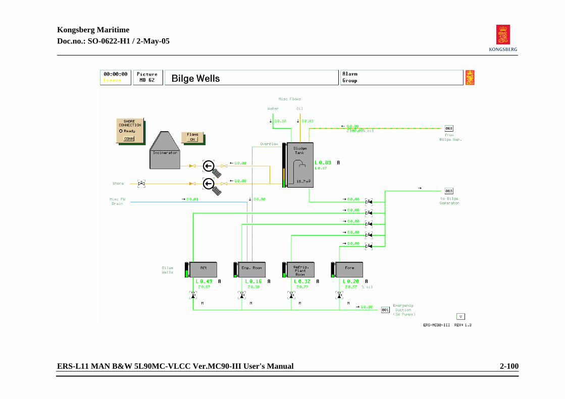
Kongsberg Maritime Doc.no.: SO-0622-H1 / 2-May-05
ERS-L11 MAN B&W 5L90MC-VLCC Ver.MC90-III User's Manual 2-100
Kongsberg Maritime Doc.no.: SO-0622-H1 / 2-May-05
ERS-L11 MAN B&W 5L90MC-VLCC Ver.MC90-III User's Manual 2-101
2.1.34 Bilge Wells Related systems required to be in operation:
Main bus bar to be active. Starting procedure: MANUAL mode:
There are 4 bilge wells and one sludge tank which can be emptied by bilge pump. From the sludge tank the oil can be pumped to the Incinerator. Select one of the bilge wells and start the bilge pump (MD63).
AUTO mode: As in manual. After start of bilge pump, set pump control in AUTO.
Incinerator operation:
Open valve from sludge tank to burner pump. Open valve to incinerator. Start incinerator by pushing flame ON. Incinerator will automatically stop at low level in sludge tank. When the ship is stopped and moored, the “shore connection” ready lamp will be lit, and we are able to pump the sludge to shore.
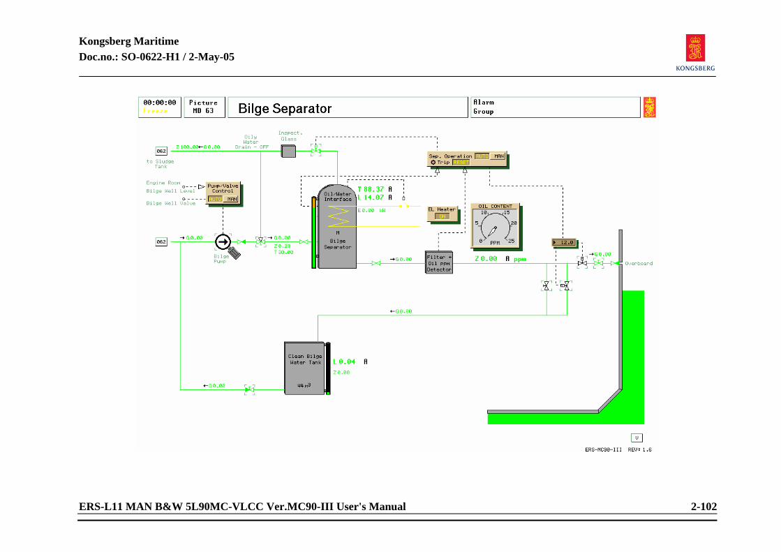
Kongsberg Maritime Doc.no.: SO-0622-H1 / 2-May-05
ERS-L11 MAN B&W 5L90MC-VLCC Ver.MC90-III User's Manual 2-102
Kongsberg Maritime Doc.no.: SO-0622-H1 / 2-May-05
ERS-L11 MAN B&W 5L90MC-VLCC Ver.MC90-III User's Manual 2-103
2.1.35 Bilge Separator Related systems required to be in operation:
Main bus bar to be active. Starting procedure: MANUAL mode:
Select picture open valves to bilge separator and overboard. START electric heating of bilge separator, set separator operation in MANUAL. When sufficient temperature, start bilge pump in manual. Observe PPM-meter to avoid pumping oil overboard.
AUTO mode: As in manual mode. After start of bilge pump, set pump control in AUTO. Set separator operation in AUTO to automatically discharge water overboard or return to sludge tank. When PPM-meter detects values above set limit, return will flow to suction side of bilge pump.
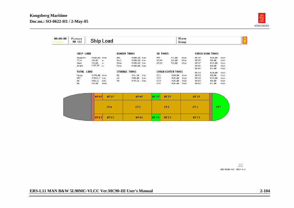
Kongsberg Maritime Doc.no.: SO-0622-H1 / 2-May-05
ERS-L11 MAN B&W 5L90MC-VLCC Ver.MC90-III User's Manual 2-104
Kongsberg Maritime Doc.no.: SO-0622-H1 / 2-May-05
ERS-L11 MAN B&W 5L90MC-VLCC Ver.MC90-III User's Manual 2-105
2.1.36 Ship Load Read only, no actions available. To change data, access to tank contents in instructor mode only through variable list pages 5700.
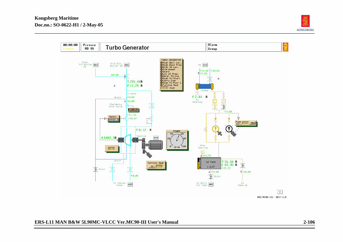
Kongsberg Maritime Doc.no.: SO-0622-H1 / 2-May-05
ERS-L11 MAN B&W 5L90MC-VLCC Ver.MC90-III User's Manual 2-106
Kongsberg Maritime Doc.no.: SO-0622-H1 / 2-May-05
ERS-L11 MAN B&W 5L90MC-VLCC Ver.MC90-III User's Manual 2-107
2.1.37 Turbo Generator Related systems to be in operations:
Steam generation plant. Steam condenser.
Preparations before starting:
Vacuum must be established and the condenser drained empty by starting the vacuum pump and main condensate pump. It is not possible to obtain sufficient vacuum if the sealing steam has not been opened, because of air leakage through shaft sealings. If the cargo turbines are out of operation, their exhaust valves should be closed to avoid extra air leakage into the condenser. The main steam line and turbine should be drained. The turbo-generator lub. oil. tank should be drained, and new oil added if necessary. Start the LO pump and set pump controller to AUTO.
Starting procedure Turbo-generator:
Press ON button (TG start/stop control oil). Open emergency stop valve slowly. Run the turbine at approximately 1200 RPM during a period of 2 minutes.
Kongsberg Maritime Doc.no.: SO-0622-H1 / 2-May-05
ERS-L11 MAN B&W 5L90MC-VLCC Ver.MC90-III User's Manual 2-108
Increase the speed to approximately 4000 RPM during a period of 2 minutes. Open emergency stop valve completely and the governor will control the RPM according to the setpoint. Check the lub oil temperature. If it is below 25°C (77°F) wait, otherwise proceed to next step. Open the emergency stop valve completely. The governor will take control as the speed approaches setpoint. Check temperature in lub. oil tank. Open up for water flow to the lub oil cooler when the temperature is above 40°C (104°F).
Stop procedure Turbo-generator:
Close the emergency stop valve. Close the sealing steam stop valve. Stop the electric lub. oil pump. Stop the vacuum pump and the condensate pump. Close the lub. oil cooler water supply valve. Close exhaust valves on the turbo-generator.

Kongsberg Maritime Doc.no.: SO-0622-H1 / 2-May-05
ERS-L11 MAN B&W 5L90MC-VLCC Ver.MC90-III User's Manual 2-109
<This page is intentionally left blank>
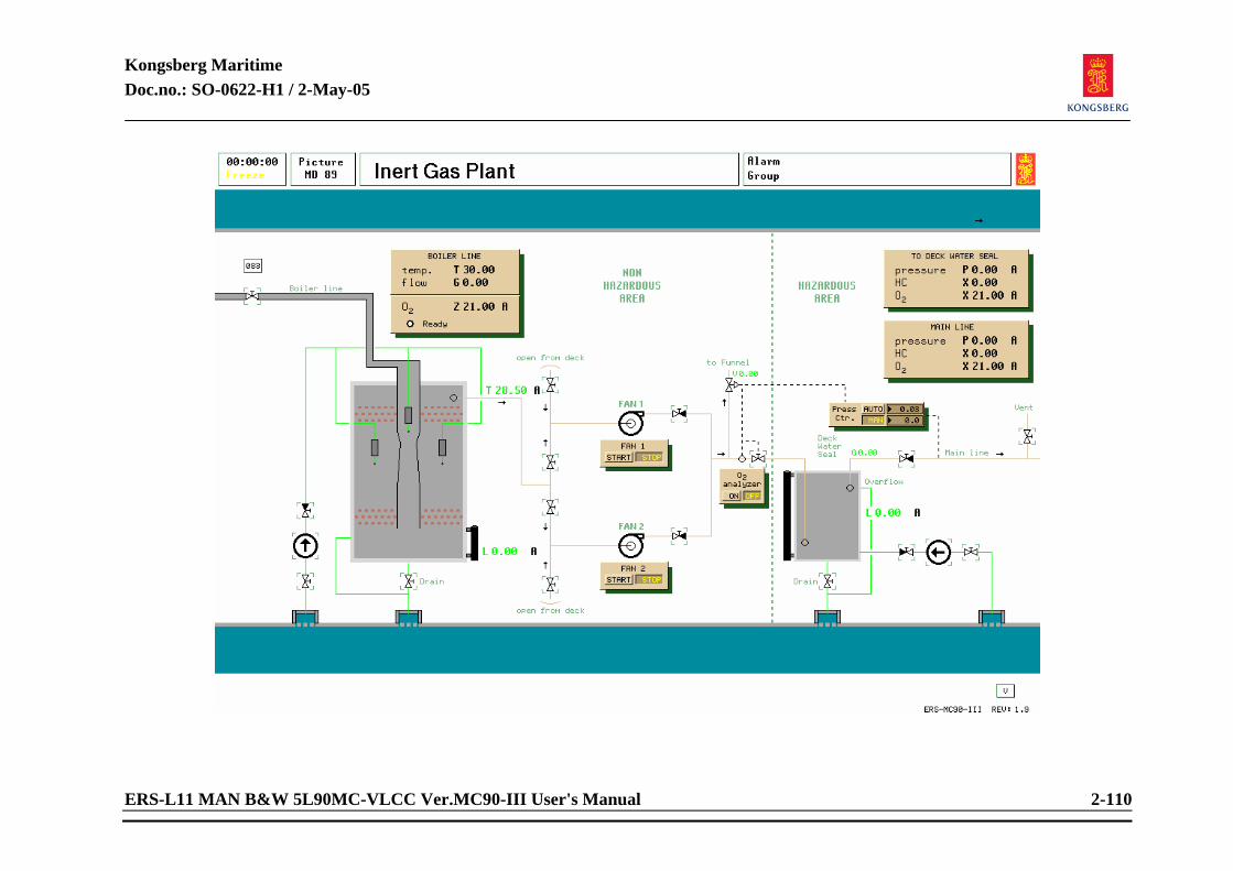
Kongsberg Maritime Doc.no.: SO-0622-H1 / 2-May-05
ERS-L11 MAN B&W 5L90MC-VLCC Ver.MC90-III User's Manual 2-110
Kongsberg Maritime Doc.no.: SO-0622-H1 / 2-May-05
ERS-L11 MAN B&W 5L90MC-VLCC Ver.MC90-III User's Manual 2-111
2.1.38 Inert Gas Plant Related system to be in operation:
Oil fired boiler.
Preparation before starting: Open SW valves to deck seal start pump. Stop pump and close valves when water level is reached in deck seal. Open Inert Gas scrubber pump sea chest valve and discharger valve.
Starting Procedure: Start scrubber pump. Line up for inert gas, start fan. Set pressure controller to AUTO. Set O2 controller ON. Inert Gas flow is dependent on Cargo flow.
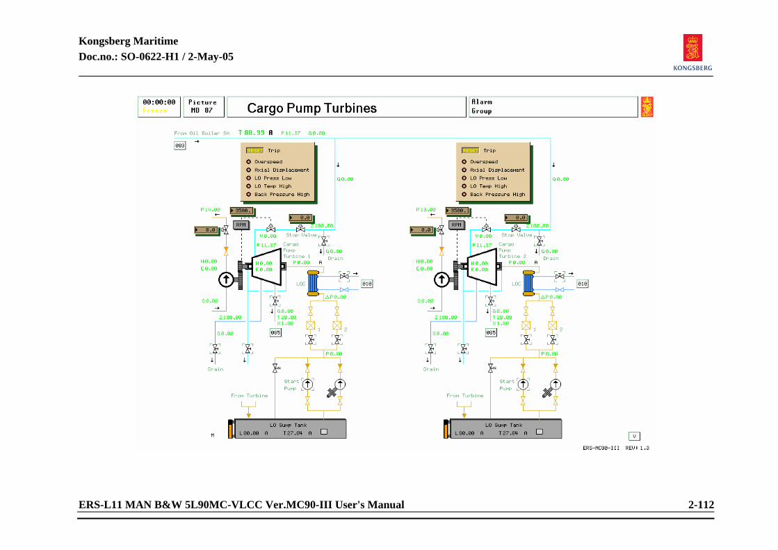
Kongsberg Maritime Doc.no.: SO-0622-H1 / 2-May-05
ERS-L11 MAN B&W 5L90MC-VLCC Ver.MC90-III User's Manual 2-112
Kongsberg Maritime Doc.no.: SO-0622-H1 / 2-May-05
ERS-L11 MAN B&W 5L90MC-VLCC Ver.MC90-III User's Manual 2-113
2.1.39 Cargo Turbines Starting procedure cargo turbine:
Open the exhaust stop valve. Open main steam valve inlet. Before opening, be sure that the throttle valve is closed. Open the throttle valve slowly. Run the turbine at approximately 800 RPM during a period of 2 minutes. Increase the speed to approximately 4000RPM during a period of 2 minutes. Open the throttle valve completely.
Stop procedure cargo turbine:
Close the throttle valve slowly. Run the turbine at approximately 800 RPM for about 5 minutes. Close the throttle valve. Close main inlet and exhaust valves. When one cargo turbine has been started, a small pause should be made before start of next turbine to permit the boiler system to recover from the shock caused by the sudden steam load increase. With all cargo turbines in operation, special attention should be paid to the boiler system which is then working at its ultimate capacity limits. The main condensate pump is sufficient for the turbo-generator load. At cargo discharging the auxiliary condensate pump must be started.
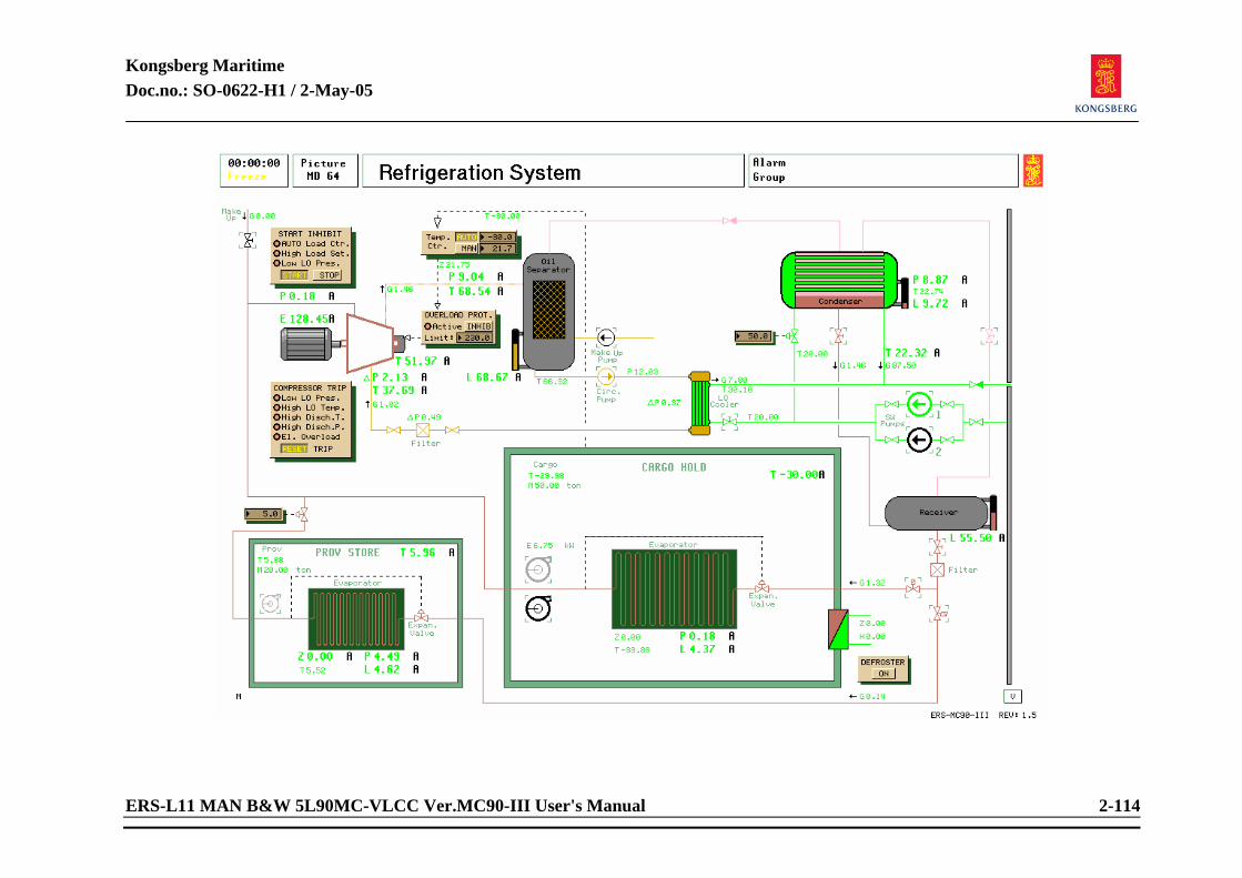
Kongsberg Maritime Doc.no.: SO-0622-H1 / 2-May-05
ERS-L11 MAN B&W 5L90MC-VLCC Ver.MC90-III User's Manual 2-114
Kongsberg Maritime Doc.no.: SO-0622-H1 / 2-May-05
ERS-L11 MAN B&W 5L90MC-VLCC Ver.MC90-III User's Manual 2-115
2.1.40 Refrigeration System Related systems required to be in operation: Main bus bar to be active.
Sea water cooling system to be active. Starting procedure: MANUAL mode:
Open valves in lub. oil system and start pump. Check and refill lub oil if necessary. Refilling of lub. oil by running make-up pump. Open vapour valve between compressor and condenser. Open vapour and liquid valves between condenser and receiver. Open sea water cooling valves to lub oil cooler and condenser. Condenser regulator must be set to a suitable level to maintain steady condensation pressure. As refrigerant is used R22, but R12 can be selected in variables list. Pressures to be set accordingly. Start compressor, reset tripping functions if necessary by pressing RESET on compressor panel. Start forced draft fans in compartment. Open liquid valve out from receiver. The supply valves to evaporators open automatically when the compressor is starting or stopping. Normal refrigeration pressure for R22 is appr. 4 to 5 barG. Refill refrigerant by opening make-up valve if necessary. Operational note: Pressure control must be set to less than 10% when starting, otherwise compressor will overload.
AUTO mode: Preparation as in manual mode. Set Pressure control to less than 10% before compressor start. (Compressor will overload also in auto mode unless the compressor is started with low load.) Set Temp. control in AUTO.
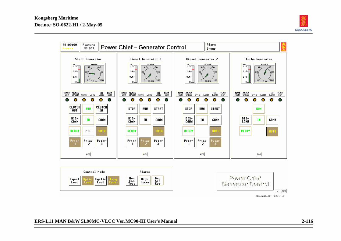
Kongsberg Maritime Doc.no.: SO-0622-H1 / 2-May-05
ERS-L11 MAN B&W 5L90MC-VLCC Ver.MC90-III User's Manual 2-116
Kongsberg Maritime Doc.no.: SO-0622-H1 / 2-May-05
ERS-L11 MAN B&W 5L90MC-VLCC Ver.MC90-III User's Manual 2-117
2.1.41 Power Chief/Gen. Control Related systems required to be in operation:
Main bus bar to be active. Sufficient starting air pressure.
Preparations before operating "Power Chief-Generator control":
Diesel generators to be ready in alarm free condition. Valves for fuel and lub. oil etc. must be opened and ready for use when starting diesel generators. (Ready lamp is lit.)
Starting procedure: MANUAL mode:
Push START button for respective generator engine. When running light appears, generator is ready for connection to main bus bar. Push button CONNECT to connect generator to main bus bar. Emergency generator will automatically disconnect and stop. Shore power must be manually disconnected. NOTE! On an actual plant, generators have to be synchronized before connecting to a live
switchboard. This feature is not modelled here, and therefore generators can be connected indiscriminately. When connecting a generator to shore power, proper frequency must be observed. More often than not, shore power frequency are 50 hertz, while ship power is 60 hertz.
Kongsberg Maritime Doc.no.: SO-0622-H1 / 2-May-05
ERS-L11 MAN B&W 5L90MC-VLCC Ver.MC90-III User's Manual 2-118
Starting and connecting second generator as described for the first one. Also without synchronization. After connection of generator(s), voltage and frequency must be checked. Select picture “ELECTRIC POWER PLANT”. Frequency is adjusted with buttons RAISE and LOWER while observing load sharing. Voltage is adjusted with MAGN. (magnetization). Click inside numeric values with centre button on tracker-ball, enter new values and press ENTER. Keep adjusting until frequency is slightly above 60 hertz and voltage slightly above 440 volt. NOTE! On an actual ship adjusting frequency and load sharing is a continuous task unless
switchboard is automated. When load changes, so does bus bar values. Ref. also DIESEL GENERATOR NO 1 and 2
Kongsberg Maritime Doc.no.: SO-0622-H1 / 2-May-05
ERS-L11 MAN B&W 5L90MC-VLCC Ver.MC90-III User's Manual 2-119
Automatic power management: There are 2 main Diesel Generators. After completion of starting preparations as described, first generator is started and connected. Press buttons AUTO and PRIORITY 1 for this generator set. Second generator set after preparing for start, READY signal will be lit on POWER CHIEF panel. Press buttons AUTO and PRIORITY 2 for this generator. CONTROL MODE selects various automated power management functions.
Shaft generator: The static converter permits flexible operation of the Shaft Generator. It can be connected when the ME speed is above 34 rpm. (45%) Full power is available when ME speed is higher than 56 rpm. (75%). It should be operated as a base generator with priority selection 1. Note that it will not act as a stand by generator in a black out situation. Therefore be sure always to have at least one diesel generator in AUTO (stand by) when operating only on the Shaft Generator.
When running, connects and disconnects as diesel generators. When READY, can be placed in AUTO as other generators.
Turbo generator:
When the steam pressure produced in the exhaust boiler is higher than 8 bar, start the turbo-generator locally. Connect the turbo-generator manually and adjust load from the main switch board. When steam conditions are stable, transfer to AUTO. The boiler combustion control should be prepared and in AUTO mode, ready for automatic start up of burners. The Burner Management load setting selection should be “LOW”. The essence of a turbo-generator is to utilize excess energy (waste heat) in main engine exhaust gases. Therefore T/G is mainly run when waste heat is to be recovered.
Kongsberg Maritime Doc.no.: SO-0622-H1 / 2-May-05
ERS-L11 MAN B&W 5L90MC-VLCC Ver.MC90-III User's Manual 2-120
Equal Load Balances load evenly between generator sets when 2 is running simultaneously.
Optimal Load
Provides maximum fuel economy. (Highest priority takes “max load” while lower priority takes the rest of the load.) Refer to chapter 4.
Cyclic Load (Asymmetric load sharing) Runs one generator maximum load alternately in preset intervals. This function prevents fouling of engine internal since engines are periodically run full load with full scavenging air pressure and flow.
Frequency Control
Controls frequency on both or one generator. Non Essential Load Trip
Flashes when alternators have been overloaded and non essentials are tripped. Reset function by clicking on button.
High Power
Flashes when generator set reaches upper limit (appr. 780 kW). To reset/acknowledge alarm click flashing button.
Generator Stand-by Start Request
Flashing button indicates upper load limit (appr. 600 kW) is near for running set. If in manual mode, start second generator set.

Kongsberg Maritime Doc.no.: SO-0622-H1 / 2-May-05
ERS-L11 MAN B&W 5L90MC-VLCC Ver.MC90-III User's Manual 2-121
<This page is intentionally left blank>
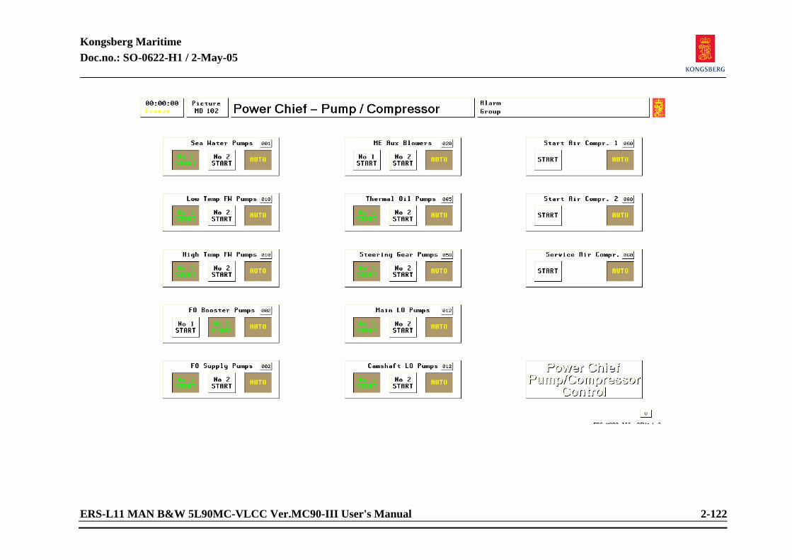
Kongsberg Maritime Doc.no.: SO-0622-H1 / 2-May-05
ERS-L11 MAN B&W 5L90MC-VLCC Ver.MC90-III User's Manual 2-122
Kongsberg Maritime Doc.no.: SO-0622-H1 / 2-May-05
ERS-L11 MAN B&W 5L90MC-VLCC Ver.MC90-III User's Manual 2-123
2.1.42 Power Chief/Pump/Comp. Control Related systems required to be in operation:
Main bus bar active. Preparations before starting:
Select respective system pictures for pumps and compressors and prepare for start of components. Valves and operating conditions must be within operating specifications.
Starting procedure: MANUAL mode:
Push START button. When steady light, pump/compressor is running. Pushing button on running pump/compressor will stop the pump/compressor, and light will extinguish.
AUTO mode: As in manual mode. When first pump/compressor is running push button AUTO. Changing pumps/compressors in AUTO, push AUTO. Start selected pump/compressor and stop running pump/compressor. Push button AUTO. NOTE! If an object has developed faults, or attempting to run object without f.ex. opening
valves, stand by pump/compressor will start. Indicated by flashing start button. To remedy condition, stop object. Locate problem and “repair”. After a repair attempt or rectifying of running condition, follow normal AUTO procedure.
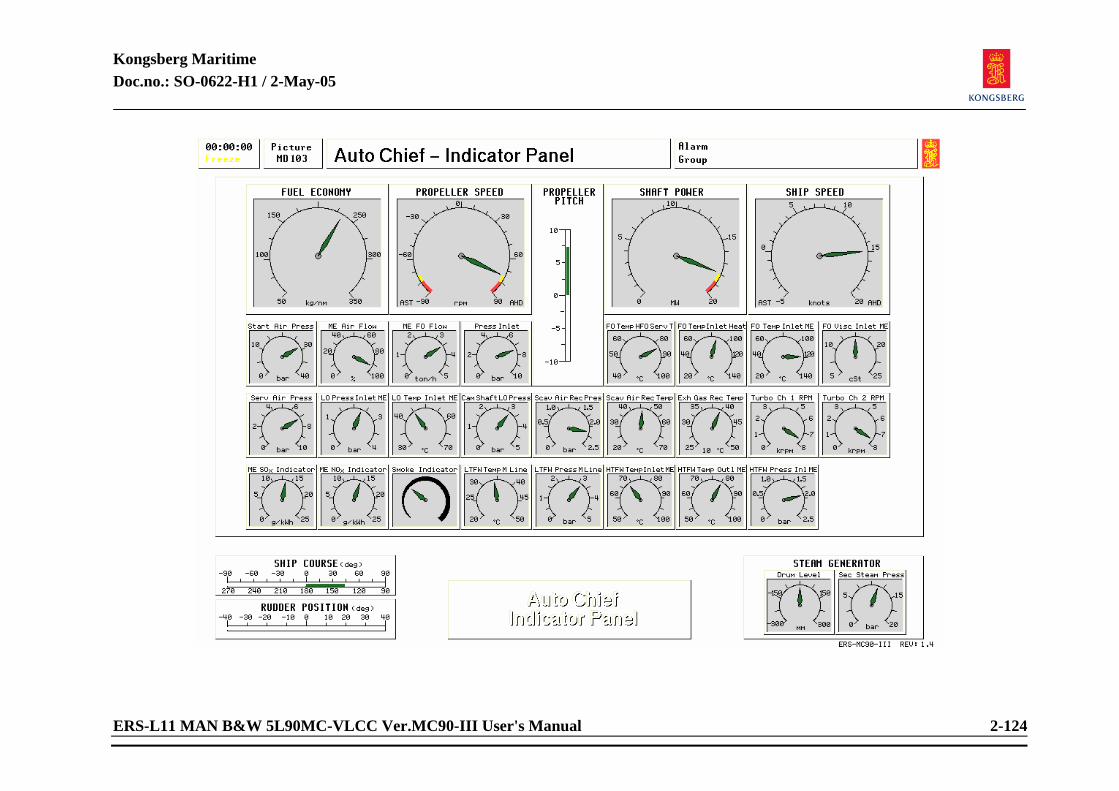
Kongsberg Maritime Doc.no.: SO-0622-H1 / 2-May-05
ERS-L11 MAN B&W 5L90MC-VLCC Ver.MC90-III User's Manual 2-124
Kongsberg Maritime Doc.no.: SO-0622-H1 / 2-May-05
ERS-L11 MAN B&W 5L90MC-VLCC Ver.MC90-III User's Manual 2-125
2.1.43 Auto Chief/Indicator Panel Read only, no actions.
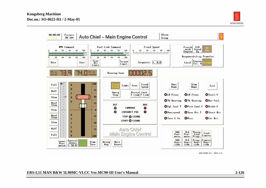
Kongsberg Maritime Doc.no.: SO-0622-H1 / 2-May-05
ERS-L11 MAN B&W 5L90MC-VLCC Ver.MC90-III User's Manual 2-126
Kongsberg Maritime Doc.no.: SO-0622-H1 / 2-May-05
ERS-L11 MAN B&W 5L90MC-VLCC Ver.MC90-III User's Manual 2-127
2.1.44 Auto Chief Control Panel Related systems required to be in operation:
Main bus bar active. Main engine with related subsystems.
Starting procedure:
Note that Slow turning should be performed if the ME has stand still for more than 30 minutes. ME Slow turning is carried out by pressing the Slow Turn. button. Check that start air block valve is open. Check that start air distributor block valve is open. Check that indicator cocks are closed. Check that turning gear is disengaged. Reset any slow down or shut down alarms. The speed lever must be set to stop position to be able to reset any shut downs. Check that no safety overrides are present.
Start in fixed pitch mode: Move handle to Slow by point and click on the interactive field or by typing in desired command in the numeric window.
Start in Combinator mode: Press the combi start/stop button. Move speed lever or type in desired command in the
numeric window.
Kongsberg Maritime Doc.no.: SO-0622-H1 / 2-May-05
ERS-L11 MAN B&W 5L90MC-VLCC Ver.MC90-III User's Manual 2-128
Speed Command Limiting graph shows any speed limiter active in the system. Actuator graph can not exceed limiting graph.
Fuel Link Command Actuator graph can not exceed limiting graph. Limiting graph is present when either torque limiter or scavenging air limiter is active.
Fixed Speed
Shows set speed from numeric window either as a graph or numeric values in percentage of load. To select FIXED SPEED: Enter new speed by clicking on numeric window and enter desired speed. Press FIXED SPEED button.
Responsibility Transfer Acknowledge either conditions from bridge by clicking flashing button. Either Engine control room, Bridge control or Local control related to manoeuvring positions or Engine control room stand by or Finished with engines as related to engine staff preparedness level.
Governor/regulator response -Fixed pitch
When this mode is chosen by clicking the button, propeller pitch will be fixed and the only variable by manoeuvring is propeller speed.
Kongsberg Maritime Doc.no.: SO-0622-H1 / 2-May-05
ERS-L11 MAN B&W 5L90MC-VLCC Ver.MC90-III User's Manual 2-129
-Combi
Meaning combinator mode. When chosen, a preset curve with both propeller speed and related propeller pitch will be chosen. This mode ensures lesser stress in propulsion engine during manoeuvring.
-Shaft generator
This mode is intended to be used only if the present plant has a directly driven Shaft Generator. When chosen, this means that shaft generator is active and connected to main bus bar. When a slow down occurs, slow down of engine is halted in order for PowerChief/Generator Control to start additional auxiliary engines and connect to Main Switchboard in order to prevent a blackout condition.
-Thermal limiter
Active when engine load is increasing too fast or when engine is overloaded. The thermal limiter can, if necessary due to an emergency situation, be overridden by pressing the “Program Override” button.
-Direct fuel link
To be activated when fault occurs in main engine governor unit. Acts as if engine control handle and fuel linkage are directly related to each others position. I.e. when ECR handle is 50%, fuel link responds with 50% output.
RPM WILL NOT BE CONTROLLED IN THIS MODE. CONTROL OF RPM IS OPERATOR’S ACTIONS WITH HANDLE.
Kongsberg Maritime Doc.no.: SO-0622-H1 / 2-May-05
ERS-L11 MAN B&W 5L90MC-VLCC Ver.MC90-III User's Manual 2-130
-Lock fuel link
Lock fuel linkage in present position when activated.
Manoeuvring of engine in ECR mode Acknowledge desired speed either direction or stop by clicking the flashing button. Button will then get steady light. Speed and direction of thrust are then carried out by point and click on the interactive fields along the speed lever or by typing in desired direction and speed in the numeric window. Minus in front of numeric value sets thrust in ASTERN. Mimic diodes to the right of handle will show position of cam shaft and direction of handle. Actuation of START/STOP switches internally in handle will also be mimicked with diodes. If Wrong Way alarm is activated, the camshaft direction does not correspond with command from bridge. In the same way the Lever Mismatch alarm will come.

Kongsberg Maritime Doc.no.: SO-0622-H1 / 2-May-05
ERS-L11 MAN B&W 5L90MC-VLCC Ver.MC90-III User's Manual 2-131
<This page is intentionally left blank>
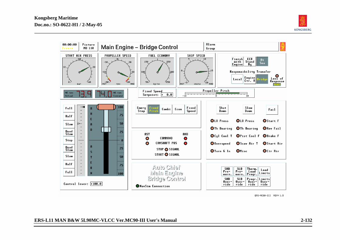
Kongsberg Maritime Doc.no.: SO-0622-H1 / 2-May-05
ERS-L11 MAN B&W 5L90MC-VLCC Ver.MC90-III User's Manual 2-132
Kongsberg Maritime Doc.no.: SO-0622-H1 / 2-May-05
ERS-L11 MAN B&W 5L90MC-VLCC Ver.MC90-III User's Manual 2-133
2.1.45 Main Engine Bridge Control Related systems required to be in operation:
Main bus bar active. Main engine related subsystems are running.
Starting procedure:
As for AutoChief Control Panel.
Transferring responsibility: As for AutoChief Control Panel
Ordering with emergency telegraph: The Bridge Telegraph Enable indication lamp has to be lit (green). This is set in the variable list, page 9010. Press selected button at emergency telegraph, the lamp is flashing until Engine Control room/Engine room answers.
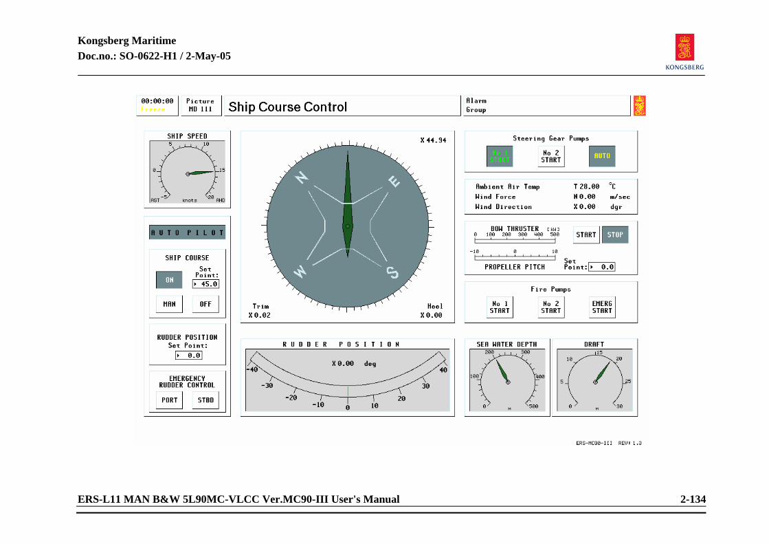
Kongsberg Maritime Doc.no.: SO-0622-H1 / 2-May-05
ERS-L11 MAN B&W 5L90MC-VLCC Ver.MC90-III User's Manual 2-134
Kongsberg Maritime Doc.no.: SO-0622-H1 / 2-May-05
ERS-L11 MAN B&W 5L90MC-VLCC Ver.MC90-III User's Manual 2-135
2.1.46 Ship Course Control Related systems required to be in operation:
Main bus bar active Propulsion machinery
Operating procedure: To set Autopilot, press button ON (can also be set from picture MD 56&58). Course can be set in numeric window either from MD 111 or MD 56 or MD58. To set Manual steering, press button MAN (can also be set from picture MD 56 and 58). Rudder position can be set or altered by clicking into numeric window (can also be set from MD 111). Rudder angle to port is set with prefixed MINUS. Emergency Steering is executed by pressing Emergency Rudder Control buttons PORT and STBD. Rudder positions can be read in the Rudder Position window. Emergency steering can also be executed from picture MD 56. Bow Thruster is started from this picture. Bow thruster propeller pitch is set in the numeric window. Bow thruster load and pitch are displayed in the bar-graphs. To start fire pumps, press desired button(s). Ambient temperature, Wind force and Wind direction are set from the variable page 9002.

Kongsberg Maritime Doc.no.: SO-0622-H1 / 2-May-05
ERS-L11 MAN B&W 5L90MC-VLCC Ver.MC90-III User's Manual 2-136

Kongsberg Maritime Doc.no.: SO-0622-H1 / 2-May-05
ERS-L11 MAN B&W 5L90MC-VLCC Ver.MC90-III User's Manual 2-137
2.1.47 Cylinder Indication Press/Angle Related systems to be in operation:
ME running Operation of recording:
In the column of INDICATE (cyl.1-5), press field button(s) (I 1 to I 5), write your comments to the indication in the field to the right of buttons I 1 to I 5.
Make your selection in the three columns of SELECT CURVE (blue, magenta, and brown), press the cylinder number to be indicated and one of the buttons I 1 to I 5 which has to correspond with the one selected in the column of INDICATE.
On the lower part of the diagram, the soft button Zoom can be used to zoom the diagram in horizontal direction to 300%. The soft button Spread is used to move overlaying curves apart.
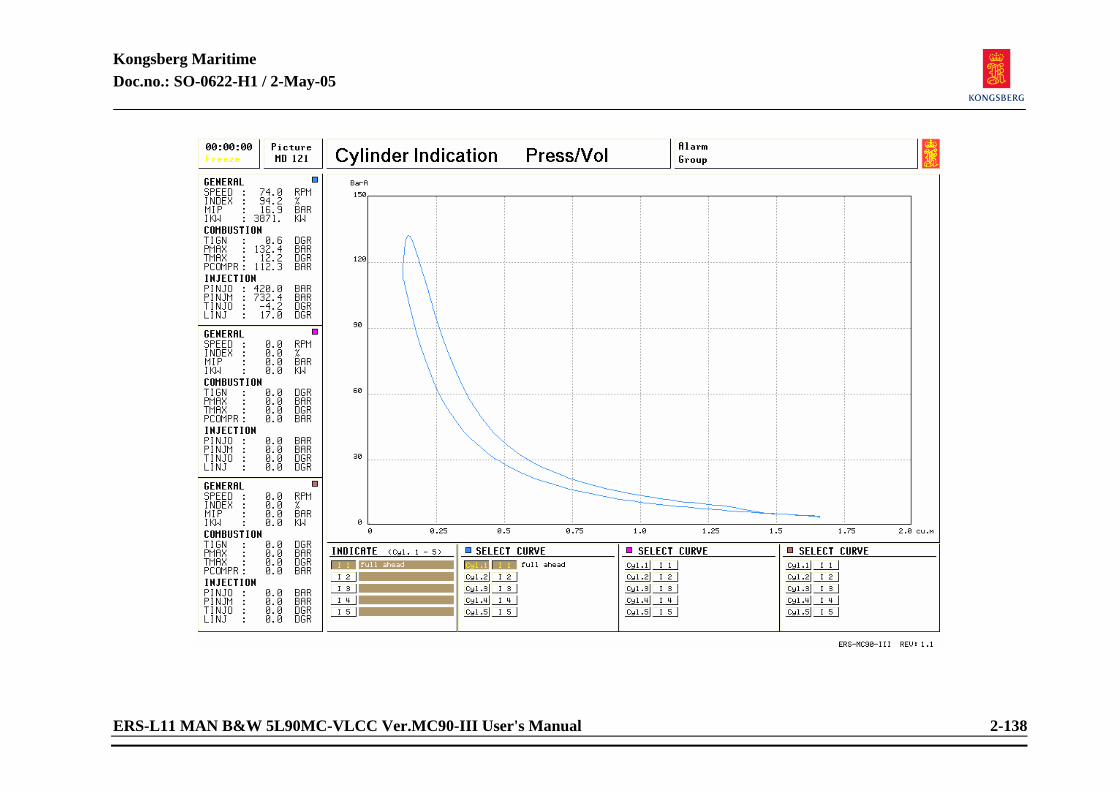
Kongsberg Maritime Doc.no.: SO-0622-H1 / 2-May-05
ERS-L11 MAN B&W 5L90MC-VLCC Ver.MC90-III User's Manual 2-138
Kongsberg Maritime Doc.no.: SO-0622-H1 / 2-May-05
ERS-L11 MAN B&W 5L90MC-VLCC Ver.MC90-III User's Manual 2-139
2.1.48 Cylinder Indication Press/Vol Related systems to be in operation:
ME running Operation of recording:
In the column of INDICATE (cyl.1-5), press field button(s) (I 1 to I 5), write your comments to the indication in the field to the right of buttons I 1 to I 5.
Make your selection in the three columns of SELECT CURVE (blue, magenta, and brown), press the cylinder number to be indicated and one of the buttons I 1 to I 5 which has to correspond with the one selected in the column of INDICATE.
On the lower part of the diagram, the soft button Zoom can be used to zoom the diagram in horizontal direction to 300%. The soft button Spread is used to move overlaying curves apart.
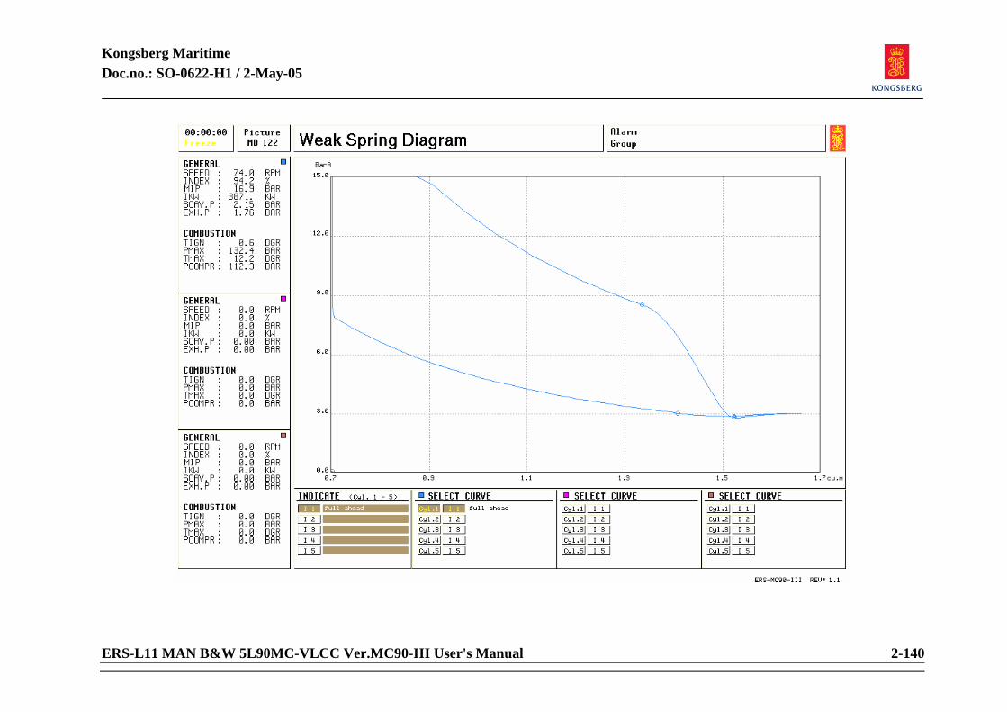
Kongsberg Maritime Doc.no.: SO-0622-H1 / 2-May-05
ERS-L11 MAN B&W 5L90MC-VLCC Ver.MC90-III User's Manual 2-140
Kongsberg Maritime Doc.no.: SO-0622-H1 / 2-May-05
ERS-L11 MAN B&W 5L90MC-VLCC Ver.MC90-III User's Manual 2-141
2.1.49 Weak Spring diagram Related systems to be in operation:
ME running Operation of recording:
In the column of INDICATE (cyl.1-5), press field button(s) (I 1 to I 5), write your comments to the indication in the field to the right of buttons I 1 to I 5.
Make your selection in the three columns of SELECT CURVE (blue, magenta, and brown), press the cylinder number to be indicated and one of I 1 to I 5 which has to correspond with the one selected in the column of INDICATE.
In the lower part of the picture, the soft button Zoom 1 can be used to zoom the diagram in vertical direction to 300%. The soft button Zoom 2 can be used to zoom the diagram in vertical direction to 600%.
NOTE: The operation of recording mentioned above is identical to the operation of
recording of Cylinder Indication Press/angle. If you have taken the diagrams of Cylinder Indication Press/angle, you can get the diagrams of High Resolution at the same time.
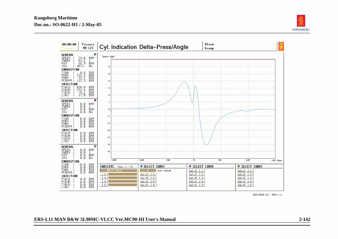
Kongsberg Maritime Doc.no.: SO-0622-H1 / 2-May-05
ERS-L11 MAN B&W 5L90MC-VLCC Ver.MC90-III User's Manual 2-142
Kongsberg Maritime Doc.no.: SO-0622-H1 / 2-May-05
ERS-L11 MAN B&W 5L90MC-VLCC Ver.MC90-III User's Manual 2-143
2.1.50 Cylinder Indication Delta-Press/Angle Related systems to be in operation:
ME running Operation of recording:
In the column of INDICATE (cyl.1-5), press field button(s) (I 1 to I 5), write your comments to the indication in the field to the right of buttons I 1 to I 5.
Make your selection in the three columns of SELECT CURVE (blue, magenta, and brown), press the cylinder number to be indicated and one of I 1 to I 5 which has to correspond with the one selected in the column of INDICATE.
NOTE: The operation of recording mentioned above is identical to the operation of
recording of Cylinder Indication Press/angle. If you have taken the diagrams of Cylinder Indication Press/angle, you can get the diagrams of Delta-Press/Angle at the same time.
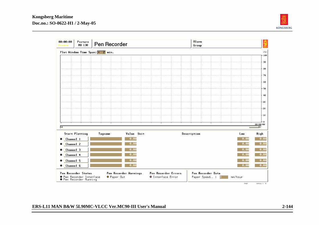
Kongsberg Maritime Doc.no.: SO-0622-H1 / 2-May-05
ERS-L11 MAN B&W 5L90MC-VLCC Ver.MC90-III User's Manual 2-144
Kongsberg Maritime Doc.no.: SO-0622-H1 / 2-May-05
ERS-L11 MAN B&W 5L90MC-VLCC Ver.MC90-III User's Manual 2-145
2.1.51 Pen Recorder Related systems required to be in operation:
The system(s) which tag(s) is to be recorded.
Preparations before recording: Select tag(s) for recording. The recorder may record six tags simultaneously. All tags in the
system may be recorded. Operation: Press button Channel 1.
Type tag no. in corresponding column (big letters). Type tag units (kg, degrees, tons, etc.). Type high limit. Type low limit. Press Start button. The graph is drawn in the same colour as the indicator lamp at the channel 1 button. Channel 2-6: As channel 1. NOTE! Paper speed can only be adjusted when an external pen recorder is connected.
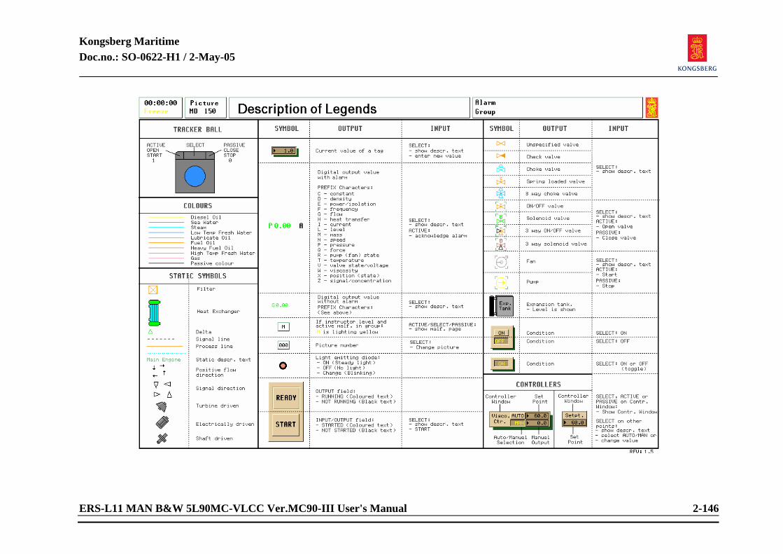
Kongsberg Maritime Doc.no.: SO-0622-H1 / 2-May-05
ERS-L11 MAN B&W 5L90MC-VLCC Ver.MC90-III User's Manual 2-146
Kongsberg Maritime Doc.no.: SO-0622-H1 / 2-May-05
ERS-L11 MAN B&W 5L90MC-VLCC Ver.MC90-III User's Manual 2-147
2.1.52 Description of Legends
This picture explains the symbols used in the different mimic pictures.

Kongsberg Maritime Doc.no.: SO-0622-H1 / 2-May-05
ERS-L11 MAN B&W 5L90MC-VLCC Ver.MC90-III User's Manual
Engine Room Simulator
ERS-L11 MAN B&W 5L90MC-VLCC Version MC90-III
USER'S MANUAL
Appendix A
Trip Codes

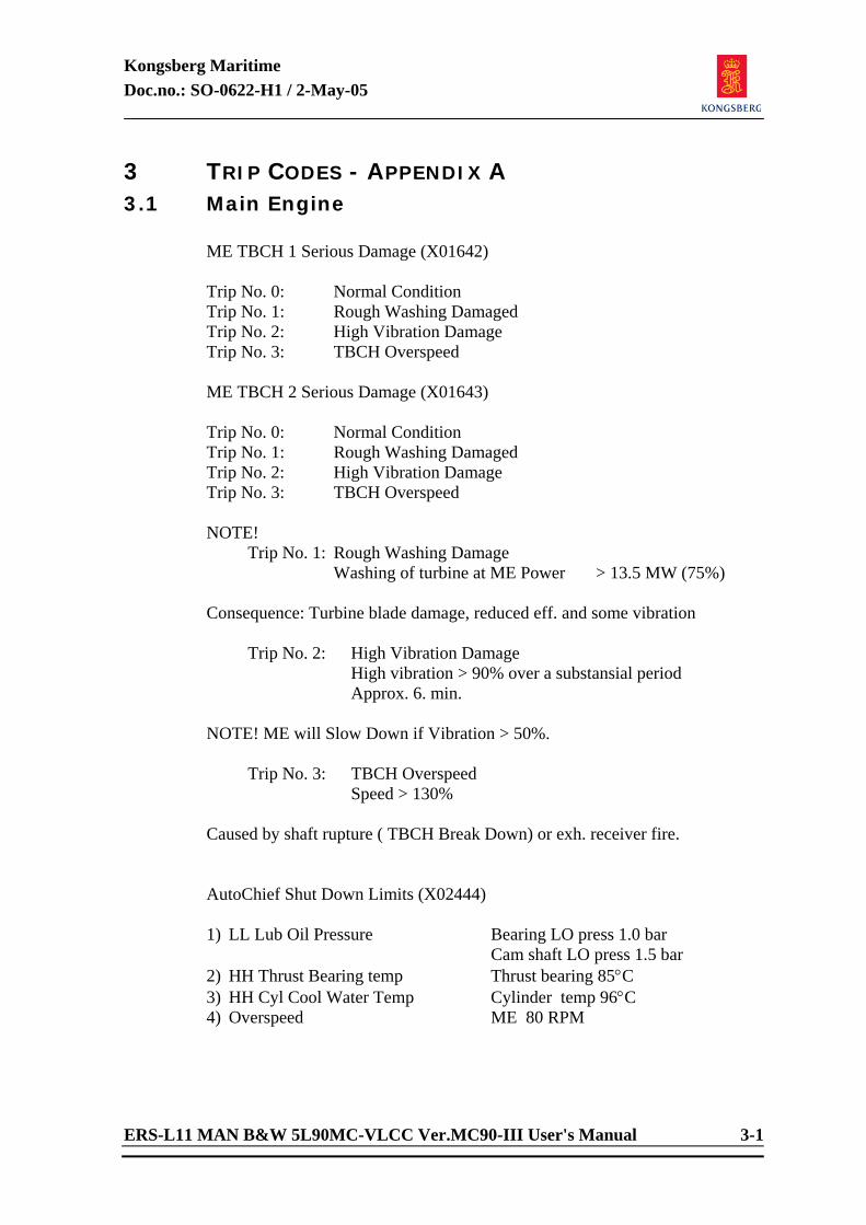
Kongsberg Maritime Doc.no.: SO-0622-H1 / 2-May-05
ERS-L11 MAN B&W 5L90MC-VLCC Ver.MC90-III User's Manual 3-1
3 TRIP CODES - APPENDIX A 3.1 Main Engine
ME TBCH 1 Serious Damage (X01642) Trip No. 0: Normal Condition Trip No. 1: Rough Washing Damaged Trip No. 2: High Vibration Damage Trip No. 3: TBCH Overspeed ME TBCH 2 Serious Damage (X01643) Trip No. 0: Normal Condition Trip No. 1: Rough Washing Damaged Trip No. 2: High Vibration Damage Trip No. 3: TBCH Overspeed NOTE! Trip No. 1: Rough Washing Damage Washing of turbine at ME Power > 13.5 MW (75%) Consequence: Turbine blade damage, reduced eff. and some vibration
Trip No. 2: High Vibration Damage High vibration > 90% over a substansial period Approx. 6. min.
NOTE! ME will Slow Down if Vibration > 50%.
Trip No. 3: TBCH Overspeed Speed > 130%
Caused by shaft rupture ( TBCH Break Down) or exh. receiver fire. AutoChief Shut Down Limits (X02444) 1) LL Lub Oil Pressure Bearing LO press 1.0 bar
Cam shaft LO press 1.5 bar 2) HH Thrust Bearing temp Thrust bearing 85°C 3) HH Cyl Cool Water Temp Cylinder temp 96°C 4) Overspeed ME 80 RPM
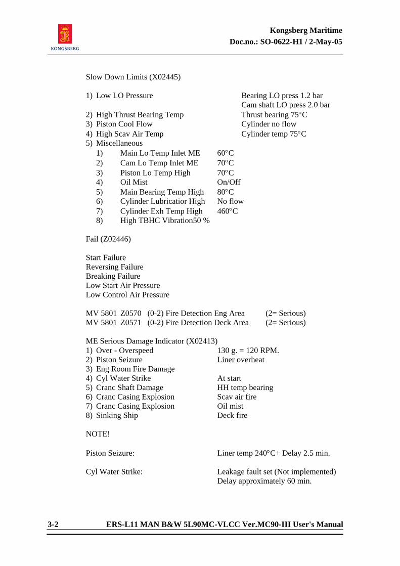
Kongsberg Maritime Doc.no.: SO-0622-H1 / 2-May-05
3-2 ERS-L11 MAN B&W 5L90MC-VLCC Ver.MC90-III User's Manual
Slow Down Limits (X02445) 1) Low LO Pressure Bearing LO press 1.2 bar
Cam shaft LO press 2.0 bar 2) High Thrust Bearing Temp Thrust bearing 75°C 3) Piston Cool Flow Cylinder no flow 4) High Scav Air Temp Cylinder temp 75°C 5) Miscellaneous 1) Main Lo Temp Inlet ME 60°C 2) Cam Lo Temp Inlet ME 70°C 3) Piston Lo Temp High 70°C 4) Oil Mist On/Off 5) Main Bearing Temp High 80°C 6) Cylinder Lubricatior High No flow 7) Cylinder Exh Temp High 460°C 8) High TBHC Vibration 50 % Fail (Z02446) Start Failure Reversing Failure Breaking Failure Low Start Air Pressure Low Control Air Pressure MV 5801 Z0570 (0-2) Fire Detection Eng Area (2= Serious) MV 5801 Z0571 (0-2) Fire Detection Deck Area (2= Serious) ME Serious Damage Indicator (X02413) 1) Over - Overspeed 130 g. = 120 RPM. 2) Piston Seizure Liner overheat 3) Eng Room Fire Damage 4) Cyl Water Strike At start 5) Cranc Shaft Damage HH temp bearing 6) Cranc Casing Explosion Scav air fire 7) Cranc Casing Explosion Oil mist 8) Sinking Ship Deck fire NOTE! Piston Seizure: Liner temp 240°C+ Delay 2.5 min. Cyl Water Strike: Leakage fault set (Not implemented)
Delay approximately 60 min.
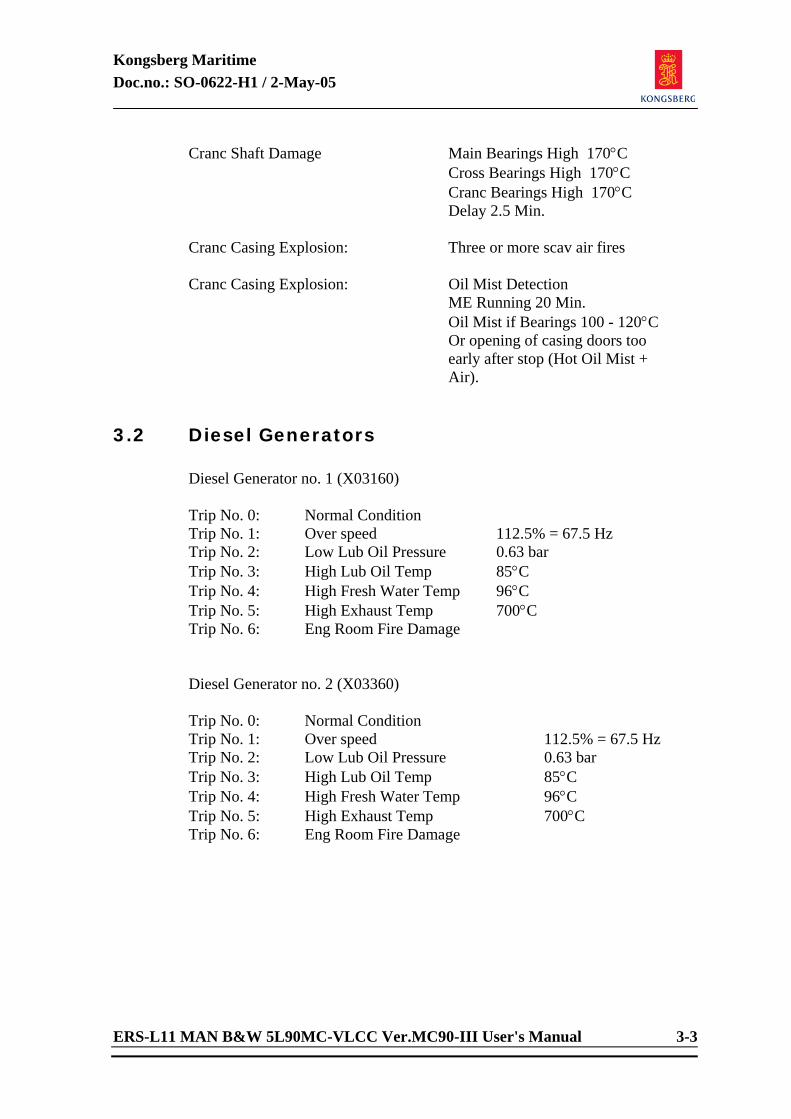
Kongsberg Maritime Doc.no.: SO-0622-H1 / 2-May-05
ERS-L11 MAN B&W 5L90MC-VLCC Ver.MC90-III User's Manual 3-3
Cranc Shaft Damage Main Bearings High 170°C Cross Bearings High 170°C Cranc Bearings High 170°C Delay 2.5 Min.
Cranc Casing Explosion: Three or more scav air fires Cranc Casing Explosion: Oil Mist Detection
ME Running 20 Min. Oil Mist if Bearings 100 - 120°C Or opening of casing doors too early after stop (Hot Oil Mist + Air).
3.2 Diesel Generators
Diesel Generator no. 1 (X03160) Trip No. 0: Normal Condition Trip No. 1: Over speed 112.5% = 67.5 Hz Trip No. 2: Low Lub Oil Pressure 0.63 bar Trip No. 3: High Lub Oil Temp 85°C Trip No. 4: High Fresh Water Temp 96°C Trip No. 5: High Exhaust Temp 700°C Trip No. 6: Eng Room Fire Damage Diesel Generator no. 2 (X03360) Trip No. 0: Normal Condition Trip No. 1: Over speed 112.5% = 67.5 Hz Trip No. 2: Low Lub Oil Pressure 0.63 bar Trip No. 3: High Lub Oil Temp 85°C Trip No. 4: High Fresh Water Temp 96°C Trip No. 5: High Exhaust Temp 700°C Trip No. 6: Eng Room Fire Damage
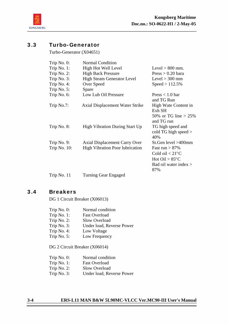
Kongsberg Maritime Doc.no.: SO-0622-H1 / 2-May-05
3-4 ERS-L11 MAN B&W 5L90MC-VLCC Ver.MC90-III User's Manual
3.3 Turbo-Generator Turbo-Generator (X04651) Trip No. 0: Normal Condition Trip No. 1: High Hot Well Level Level > 800 mm. Trip No. 2: High Back Pressure Press > 0.20 bara Trip No. 3: High Steam Generator Level Level > 300 mm Trip No. 4: Over Speed Speed > 112.5% Trip No. 5: Spare Trip No. 6: Low Lub Oil Pressure Press < 1.0 bar and TG Run Trip No.7: Axial Displacement Water Strike High Wate Content in Exh SH
50% or TG line > 25% and TG run
Trip No. 8: High Vibration During Start Up TG high speed and cold TG high speed > 40%
Trip No. 9: Axial Displacement Carry Over St.Gen level >400mm Trip No. 10: High Vibration Poor lubrication Fast run > 87%
Cold oil < 21°C Hot Oil > 85°C Bad oil water index >
87% Trip No. 11 Turning Gear Engaged
3.4 Breakers DG 1 Circuit Breaker (X06013) Trip No. 0: Normal condition Trip No. 1: Fast Overload Trip No. 2: Slow Overload Trip No. 3: Under load, Reverse Power Trip No. 4: Low Voltage Trip No. 5: Low Frequency DG 2 Circuit Breaker (X06014) Trip No. 0: Normal condition Trip No. 1: Fast Overload Trip No. 2: Slow Overload Trip No. 3: Under load, Reverse Power
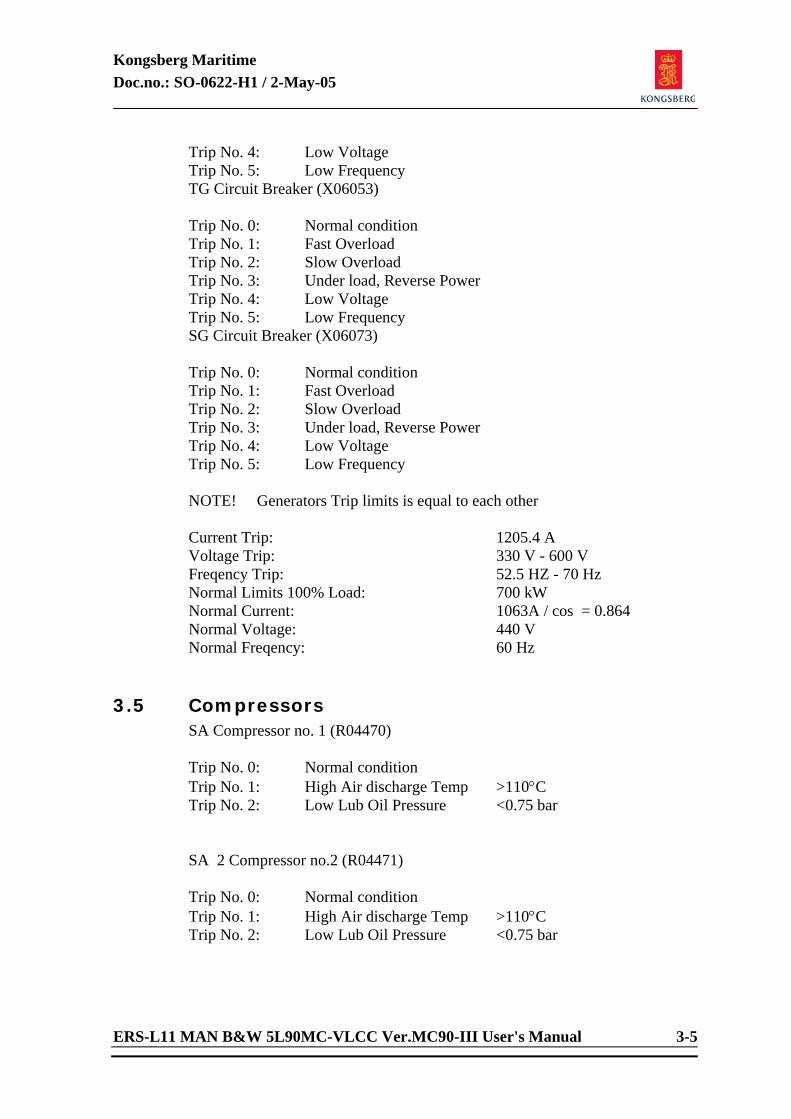
Kongsberg Maritime Doc.no.: SO-0622-H1 / 2-May-05
ERS-L11 MAN B&W 5L90MC-VLCC Ver.MC90-III User's Manual 3-5
Trip No. 4: Low Voltage Trip No. 5: Low Frequency TG Circuit Breaker (X06053) Trip No. 0: Normal condition Trip No. 1: Fast Overload Trip No. 2: Slow Overload Trip No. 3: Under load, Reverse Power Trip No. 4: Low Voltage Trip No. 5: Low Frequency SG Circuit Breaker (X06073) Trip No. 0: Normal condition Trip No. 1: Fast Overload Trip No. 2: Slow Overload Trip No. 3: Under load, Reverse Power Trip No. 4: Low Voltage Trip No. 5: Low Frequency NOTE! Generators Trip limits is equal to each other Current Trip: 1205.4 A Voltage Trip: 330 V - 600 V Freqency Trip: 52.5 HZ - 70 Hz Normal Limits 100% Load: 700 kW Normal Current: 1063A / cos = 0.864 Normal Voltage: 440 V Normal Freqency: 60 Hz
3.5 Compressors SA Compressor no. 1 (R04470) Trip No. 0: Normal condition Trip No. 1: High Air discharge Temp >110°C Trip No. 2: Low Lub Oil Pressure <0.75 bar SA 2 Compressor no.2 (R04471) Trip No. 0: Normal condition Trip No. 1: High Air discharge Temp >110°C Trip No. 2: Low Lub Oil Pressure <0.75 bar
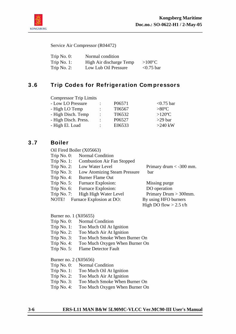
Kongsberg Maritime Doc.no.: SO-0622-H1 / 2-May-05
3-6 ERS-L11 MAN B&W 5L90MC-VLCC Ver.MC90-III User's Manual
Service Air Compressor (R04472) Trip No. 0: Normal condition Trip No. 1: High Air discharge Temp >100°C Trip No. 2: Low Lub Oil Pressure <0.75 bar
3.6 Trip Codes for Refrigeration Compressors
Compressor Trip Limits - Low LO Pressure : P06571 <0.75 bar - High LO Temp : T06567 >80ºC - High Disch. Temp : T06532 >120ºC - High Disch. Press. : P06527 >29 bar - High El. Load : E06533 >240 kW
3.7 Boiler
Oil Fired Boiler (X05663) Trip No. 0: Normal Condition Trip No. 1: Combustion Air Fan Stopped Trip No. 2: Low Water Level Primary drum < -300 mm. Trip No. 3: Low Atomizing Steam Pressure bar Trip No. 4: Burner Flame Out Trip No. 5: Furnace Explosion: Missing purge Trip No. 6: Furnace Explosion: DO operation Trip No. 7: High High Water Level Primary Drum > 300mm. NOTE! Furnace Explosion at DO: By using HFO burners High DO flow > 2.5 t/h Burner no. 1 (X05655) Trip No. 0: Normal Condition Trip No. 1: Too Much Oil At Ignition Trip No. 2: Too Much Air At Ignition Trip No. 3: Too Much Smoke When Burner On Trip No. 4: Too Much Oxygen When Burner On Trip No. 5: Flame Detector Fault Burner no. 2 (X05656) Trip No. 0: Normal Condition Trip No. 1: Too Much Oil At Ignition Trip No. 2: Too Much Air At Ignition Trip No. 3: Too Much Smoke When Burner On Trip No. 4: Too Much Oxygen When Burner On
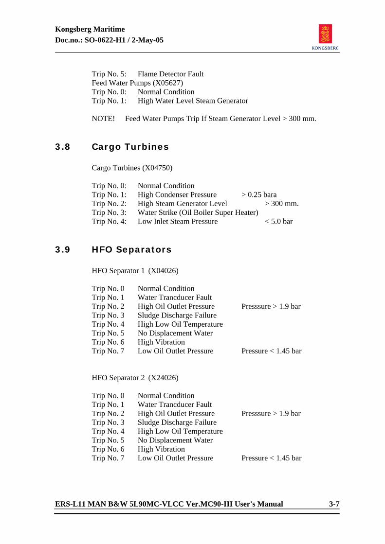
Kongsberg Maritime Doc.no.: SO-0622-H1 / 2-May-05
ERS-L11 MAN B&W 5L90MC-VLCC Ver.MC90-III User's Manual 3-7
Trip No. 5: Flame Detector Fault Feed Water Pumps (X05627) Trip No. 0: Normal Condition Trip No. 1: High Water Level Steam Generator NOTE! Feed Water Pumps Trip If Steam Generator Level > 300 mm.
3.8 Cargo Turbines
Cargo Turbines (X04750) Trip No. 0: Normal Condition Trip No. 1: High Condenser Pressure > 0.25 bara Trip No. 2: High Steam Generator Level > 300 mm. Trip No. 3: Water Strike (Oil Boiler Super Heater) Trip No. 4: Low Inlet Steam Pressure < 5.0 bar
3.9 HFO Separators HFO Separator 1 (X04026) Trip No. 0 Normal Condition Trip No. 1 Water Trancducer Fault Trip No. 2 High Oil Outlet Pressure Presssure > 1.9 bar Trip No. 3 Sludge Discharge Failure Trip No. 4 High Low Oil Temperature Trip No. 5 No Displacement Water Trip No. 6 High Vibration Trip No. 7 Low Oil Outlet Pressure Pressure < 1.45 bar HFO Separator 2 (X24026) Trip No. 0 Normal Condition Trip No. 1 Water Trancducer Fault Trip No. 2 High Oil Outlet Pressure Presssure > 1.9 bar Trip No. 3 Sludge Discharge Failure Trip No. 4 High Low Oil Temperature Trip No. 5 No Displacement Water Trip No. 6 High Vibration Trip No. 7 Low Oil Outlet Pressure Pressure < 1.45 bar

Kongsberg Maritime Doc.no.: SO-0622-H1 / 2-May-05
ERS-L11 MAN B&W 5L90MC-VLCC Ver.MC90-III User's Manual
Engine Room Simulator
ERS-L11 MAN B&W 5L90MC-VLCC Version MC90-III
USER'S MANUAL
Appendix B
Controllers and Actuators

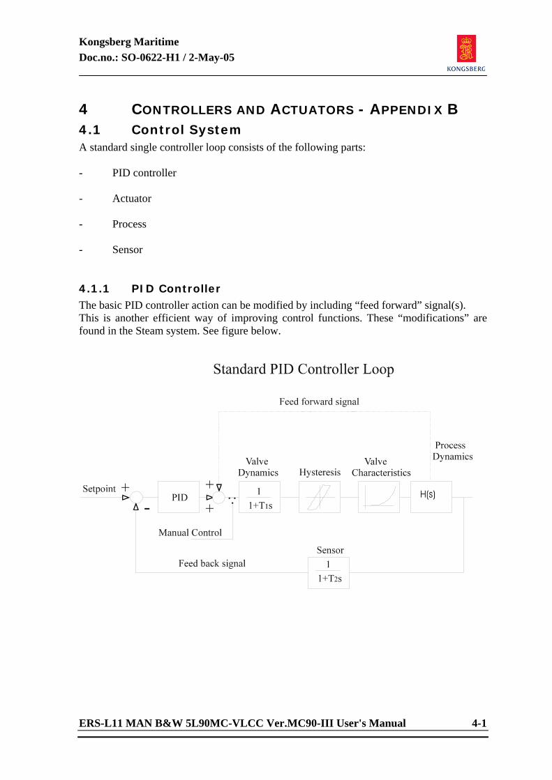
Kongsberg Maritime Doc.no.: SO-0622-H1 / 2-May-05
ERS-L11 MAN B&W 5L90MC-VLCC Ver.MC90-III User's Manual 4-1
4 CONTROLLERS AND ACTUATORS - APPENDIX B 4.1 Control System A standard single controller loop consists of the following parts: - PID controller - Actuator - Process - Sensor 4.1.1 PID Controller The basic PID controller action can be modified by including “feed forward” signal(s). This is another efficient way of improving control functions. These “modifications” are found in the Steam system. See figure below.
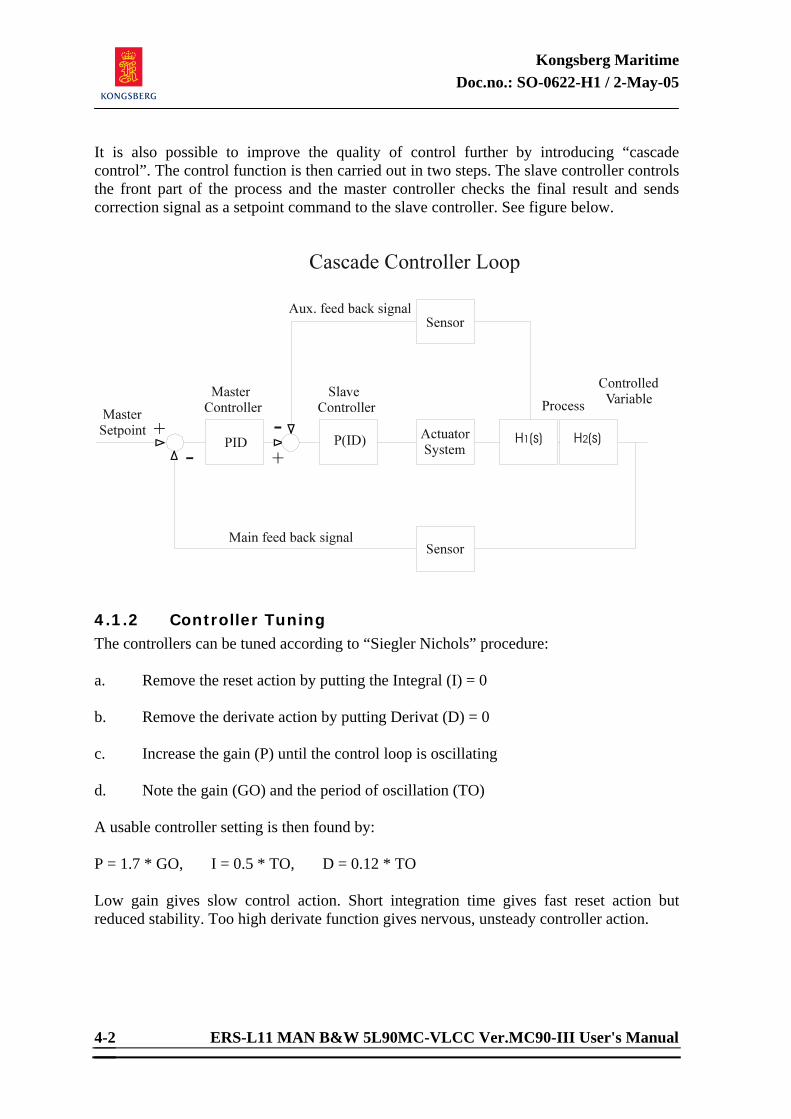
Kongsberg Maritime Doc.no.: SO-0622-H1 / 2-May-05
ERS-L11 MAN B&W 5L90MC-VLCC Ver.MC90-III User's Manual 4-2
It is also possible to improve the quality of control further by introducing “cascade control”. The control function is then carried out in two steps. The slave controller controls the front part of the process and the master controller checks the final result and sends correction signal as a setpoint command to the slave controller. See figure below.
4.1.2 Controller Tuning The controllers can be tuned according to “Siegler Nichols” procedure: a. Remove the reset action by putting the Integral (I) = 0 b. Remove the derivate action by putting Derivat (D) = 0 c. Increase the gain (P) until the control loop is oscillating d. Note the gain (GO) and the period of oscillation (TO) A usable controller setting is then found by: P = 1.7 * GO, I = 0.5 * TO, D = 0.12 * TO Low gain gives slow control action. Short integration time gives fast reset action but reduced stability. Too high derivate function gives nervous, unsteady controller action.
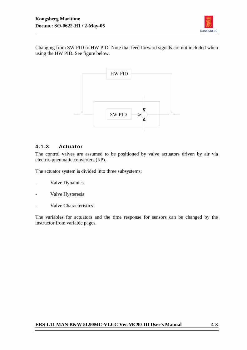
Kongsberg Maritime Doc.no.: SO-0622-H1 / 2-May-05
ERS-L11 MAN B&W 5L90MC-VLCC Ver.MC90-III User's Manual 4-3
Changing from SW PID to HW PID: Note that feed forward signals are not included when using the HW PID. See figure below.
4.1.3 Actuator The control valves are assumed to be positioned by valve actuators driven by air via electric-pneumatic converters (I/P). The actuator system is divided into three subsystems; - Valve Dynamics - Valve Hysteresis - Valve Characteristics The variables for actuators and the time response for sensors can be changed by the instructor from variable pages.
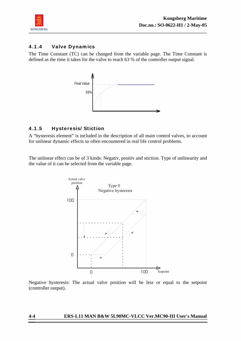
Kongsberg Maritime Doc.no.: SO-0622-H1 / 2-May-05
ERS-L11 MAN B&W 5L90MC-VLCC Ver.MC90-III User's Manual 4-4
4.1.4 Valve Dynamics The Time Constant (TC) can be changed from the variable page. The Time Constant is defined as the time it takes for the valve to reach 63 % of the controller output signal.
63%
Final Value
4.1.5 Hysteresis/Stiction A “hysteresis element” is included in the description of all main control valves, to account for unlinear dynamic effects so often encountered in real life control problems. The unlinear effect can be of 3 kinds: Negativ, positiv and stiction. Type of unlinearity and the value of it can be selected from the variable page.
Negative hysteresis: The actual valve position will be less or equal to the setpoint (controller output).
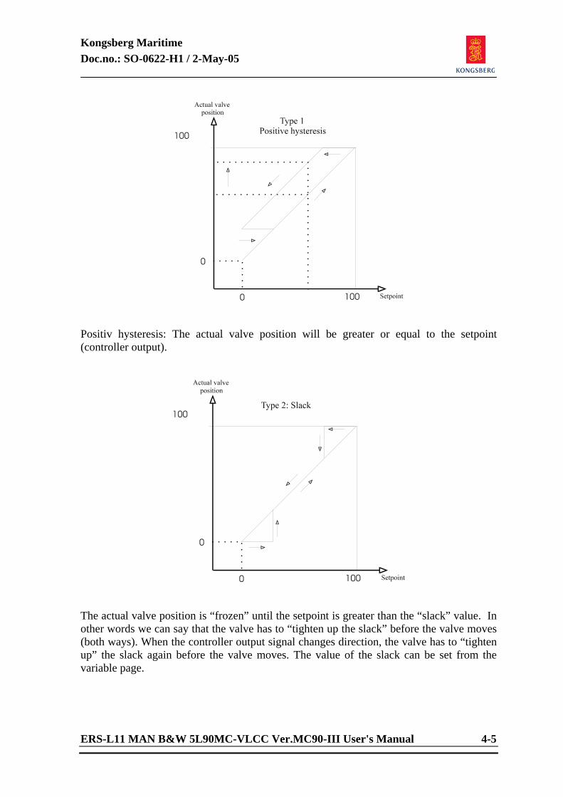
Kongsberg Maritime Doc.no.: SO-0622-H1 / 2-May-05
ERS-L11 MAN B&W 5L90MC-VLCC Ver.MC90-III User's Manual 4-5
Positiv hysteresis: The actual valve position will be greater or equal to the setpoint (controller output).
The actual valve position is “frozen” until the setpoint is greater than the “slack” value. In other words we can say that the valve has to “tighten up the slack” before the valve moves (both ways). When the controller output signal changes direction, the valve has to “tighten up” the slack again before the valve moves. The value of the slack can be set from the variable page.
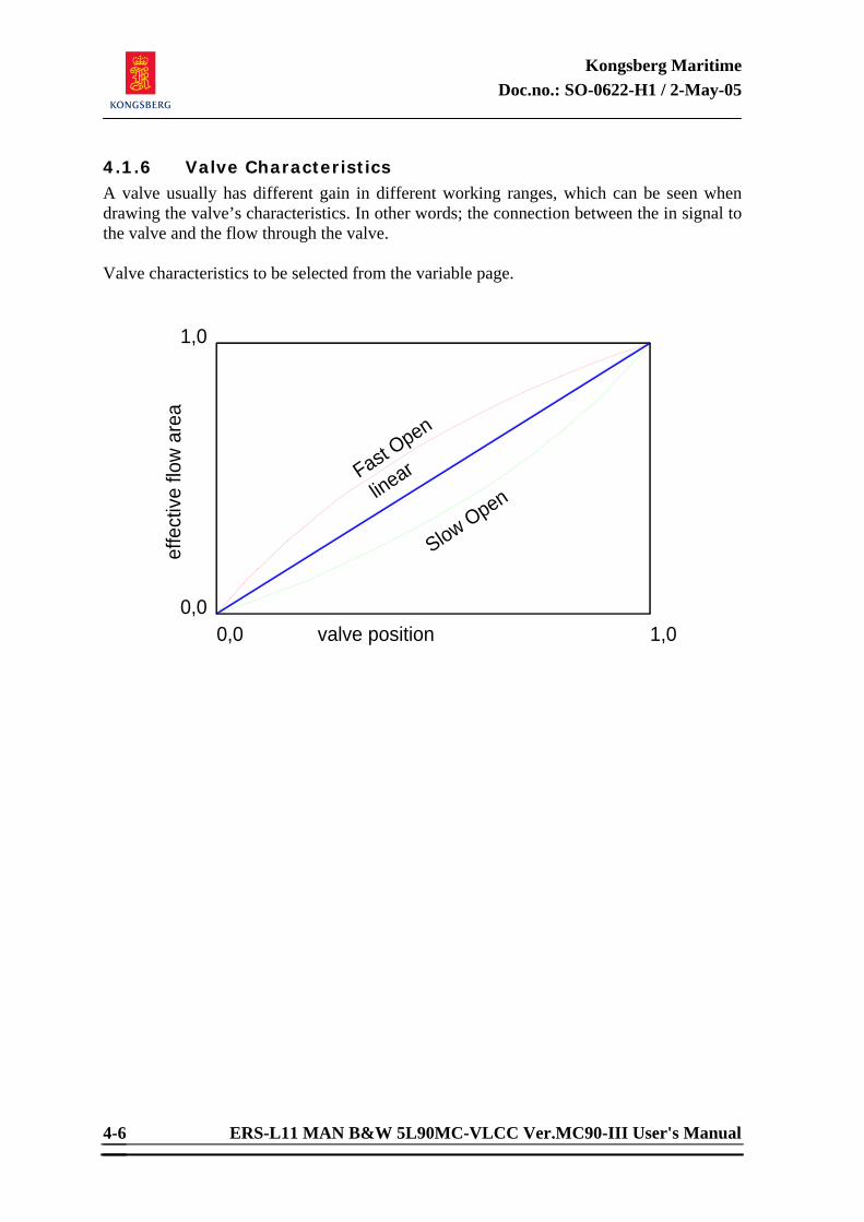
Kongsberg Maritime Doc.no.: SO-0622-H1 / 2-May-05
ERS-L11 MAN B&W 5L90MC-VLCC Ver.MC90-III User's Manual 4-6
4.1.6 Valve Characteristics A valve usually has different gain in different working ranges, which can be seen when drawing the valve’s characteristics. In other words; the connection between the in signal to the valve and the flow through the valve. Valve characteristics to be selected from the variable page.
0,0
1,0
effe
ctiv
e f lo
w a
r ea
valve position
Slow Open
0,0
linearFast Open
1,0
Kongsberg Maritime Doc.no.: SO-0622-H1 / 2-May-05
ERS-L11 MAN B&W 5L90MC-VLCC Ver.MC90-III User's Manual
Engine Room Simulator
ERS-L11 MAN B&W 5L90MC-VLCC Version MC90-III
USER'S MANUAL
Appendix C
Alarm List
Doc.no.: SO-0437

Kongsberg Maritime Doc.no.: SO-0437-I / 8-Oct-04
ERS-L11 MAN B&W 5L90MC-VLCC Ver. MC90-III Alarm List
Engine Room Simulator
ERS-L11 MAN B&W 5L90MC-VLCC Version MC90-III
ALARM LIST
Department/Author: Approved by: Berit Baggerud (s) Arild Hermansen (s)
© 2004 Kongsberg Maritime AS All rights reserved
No part of this work covered by the copyright hereon may be reproduced or otherwise copied
without prior permission from Kongsberg Maritime AS


Kongsberg Maritime Doc.no.: SO-0437-I / 8-Oct-04
ERS-L11 MAN B&W 5L90MC-VLCC Ver. MC90-III Alarm List i
DOCUMENT STATUS Issue No. Date/Year Inc. by Issue No. Date/Year Inc. by SO-0437-A 17.10.95 ASJ/td SO-0437-I 8-Oct-04 HD/beba SO-0437-B 08.07.96 ASJ/td SO-0437-C 21.03.97 ASJ/beba SO-0437-D 25.10.99 AHE/beba SO-0437-E 16.05.00 AHE/beba SO-0437-F 25-Sep-02 AHE/beba SO-0437-G 28-Jan-03 AHE/beba SO-0437-H 10-Jun-03 AHE/beba
CHANGES IN DOCUMENT Issue ECO Paragraph Paragraph Heading/ No. No. No. Description of Change A First issue. B MP36-96 All Upgrade Alarm list to last revision. C MP-1052 All Upgrade Alarm List to latest version. D MP-1301 All Upgrade Alarm List to latest version. E MP-1357 All Upgrade Alarm List to latest version. F MP-1431 All Upgrade Alarm List to latest version. G MP-1439 All Upgrade Alarm List to latest version. H MP-1452 All Upgrade Alarm List to latest version. I MP-1517 All Upgrade Alarm List to latest version
Kongsberg Maritime Doc.no.: SO-0437-I / 8-Oct-04
ii ERS-L11 MAN B&W 5L90MC-VLCC Ver. MC90-III Alarm List
<This page is intentionally left blank>
Kongsberg Maritime Doc.no.: SO-0437-I / 8-Oct-04
ERS-L11 MAN B&W 5L90MC-VLCC Ver. MC90-III Alarm List iii
TABLE OF CONTENTS
1 DIRECTORY LIST ....................................................................... 1
2 VARIABLE LIST PAGES................................................................ 2 2.1 Page:0101 AG01** FUEL OIL SUPPLY SYSTEM (1 - 4)................. 2 2.2 Page:0102 AG01** FO SERVICE TANKS (2 - 4).......................... 2 2.3 Page:0103 AG01** HFO SETTLING TANKS (3 - 4)....................... 3 2.4 Page:0104 AG01** SPILL OIL TANK / BUNKER TANKS ( 4 - 4) ...... 3 2.5 Page:0201 AG02** ME LO SYSTEM (1 - 2) ................................. 4 2.6 Page:0202 AG02** ME CYL OIL LUBRICATION (2 - 2).................. 4 2.7 Page:0301 AG03** ME CONTROL SYSTEM (1 - 1) ....................... 5 2.8 Page:0401 AG04** ME CYLINDER LINER COOLING (1 - 3) .......... 5 2.9 Page:0402 AG04** ME CYLINDER PISTON COOLING (2 - 3) ......... 6 2.10 Page:0403 AG04** ME CYLINDER METAL TEMPS (3 - 3) .............. 6 2.11 Page:0501 AG05** LTFW / HTFW SYSTEM (1 - 1) ....................... 7 2.12 Page:0601 AG06** START AIR SYSTEM (1 - 2)........................... 7 2.13 Page:0602 AG06** SERV AIR SYSTEM (2 - 2) ............................ 8 2.14 Page:0701 AG07** ME EXHAUST SYSTEM (1 - 1) ....................... 8 2.15 Page:0801 AG08** ME SCAVENGING AIR SYSTEM (1 - 2) ............ 9 2.16 Page:0802 AG08** ME TURBOCHARGERS (2 - 2)........................ 9 2.17 Page:0901 AG09** ME BEARING SYSTEM (crossh/cranc) (1 - 3) .10 2.18 Page:0902 AG09** ME BEARING SYSTEM (main/thrust) (2 - 3) ..10 2.19 Page:0903 AG09** ME CRANC CASING OIL MIST + MISC (3 - 3) .11 2.20 Page:1001 AG10** FIRE DETECTION SYSTEM (1 - 1) .................11 2.21 Page:1101 AG11** PROPELLER SERVO OIL SYSTEM (1 - 1).........12 2.22 Page:1201 AG12** STERN TUBE SYSTEM (1 - 1) .......................12 2.23 Page:1301 AG13** SEA WATER SYSTEM (1 - 1) ........................13 2.24 Page:1401 AG14** FRESH WATER GENERATOR (1 - 1)...............13 2.25 Page:1501 AG15** WASTE HEAT RECOVERY SYSTEM (1 - 1).......14 2.26 Page:1601 AG16** BILGE WELLS / SLUDGE TANK (1 - 1) ...........14 2.27 Page:1602 AG16** BILGE WATER SEPARATOR (1 - 1) ................15 2.28 Page:1701 AG17** PURIFIER SYSTEM (1 - 1)............................15 2.29 Page:1801 AG18** AIR CONDITION SYSTEM (1 - 1) .................16 2.30 Page:1901 AG19** ELECTRIC POWER SYSTEM 1 (1 - 3) .............16 2.31 Page:1902 AG19** ELECTRIC POWER SYSTEM 2 (2 - 3) .............17 2.32 Page:1903 AG19** ELECTRIC POWER SYSTEM 3 (3 - 3) .............17 2.33 Page:2001 AG20** DIESELGENERATOR 1.................................18 2.34 Page:2002 AG20** DIESELGENERATOR 1.................................18 2.35 Page:2003 AG20** DIESELGENERATOR 2.................................19 2.36 Page:2004 AG20** DIESELGENERATOR 2.................................19 2.37 Page:2005 AG20** SHAFTGENERATOR - PTI / PTO ....................20 2.38 Page:2101 AG21** TURBOGENERATOR (1 - 3) ..........................20 2.39 Page:2102 AG21** CARGO PUMP TURBINES (2 - 3) ...................21 2.40 Page:2103 AG21** STEAM CONDENSER (3 - 3).........................21 2.41 Page:2201 AG22** EXHAUST BOILER (1 - 1) ............................22 2.42 Page:2301 AG23** OIL FIRED BOILER (1 – 1)...........................22
Kongsberg Maritime Doc.no.: SO-0437-I / 8-Oct-04
iv ERS-L11 MAN B&W 5L90MC-VLCC Ver. MC90-III Alarm List
2.43 Page:2401 AG24** STEAM GENERATOR (1 - 1)......................... 23 2.44 Page:2501 AG25** REFRIGERATION SYSTEM (1 - 2) ................. 23 2.45 Page:2502 AG25** REFRIGERATION SYSTEM (2 - 2) ................. 24 2.46 Page:2601 AG26** INERT GAS SYSTEM (1 - 1 )......................... 24 2.47 Page:2701 AG27** STEERING GEAR SYSTEM (1 - 1) ................ 25 2.48 Page:2801 AG28** FRESH WATER SANITARY (1 - 1) ................. 25 2.49 Page:2802 AG28** REMOTE EMERGENCY PANEL (1 - 1)............. 26
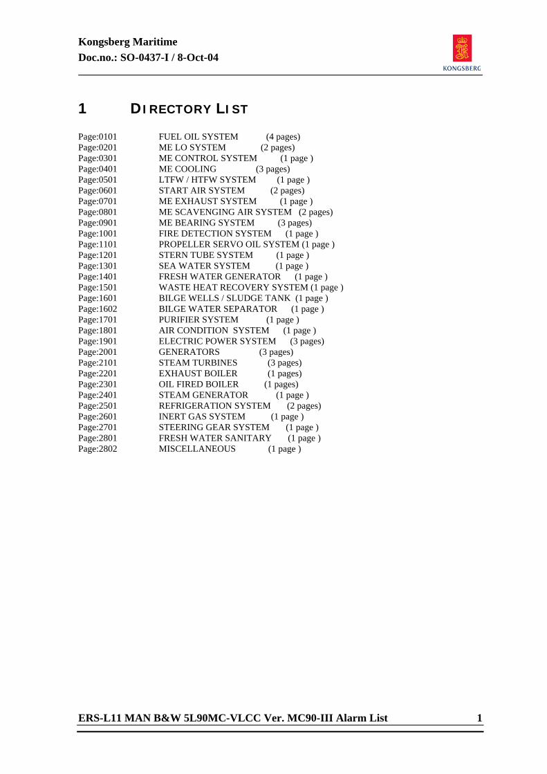
Kongsberg Maritime Doc.no.: SO-0437-I / 8-Oct-04
ERS-L11 MAN B&W 5L90MC-VLCC Ver. MC90-III Alarm List 1
1 DIRECTORY LIST Page:0101 FUEL OIL SYSTEM (4 pages) Page:0201 ME LO SYSTEM (2 pages) Page:0301 ME CONTROL SYSTEM (1 page ) Page:0401 ME COOLING (3 pages) Page:0501 LTFW / HTFW SYSTEM (1 page ) Page:0601 START AIR SYSTEM (2 pages) Page:0701 ME EXHAUST SYSTEM (1 page ) Page:0801 ME SCAVENGING AIR SYSTEM (2 pages) Page:0901 ME BEARING SYSTEM (3 pages) Page:1001 FIRE DETECTION SYSTEM (1 page ) Page:1101 PROPELLER SERVO OIL SYSTEM (1 page ) Page:1201 STERN TUBE SYSTEM (1 page ) Page:1301 SEA WATER SYSTEM (1 page ) Page:1401 FRESH WATER GENERATOR (1 page ) Page:1501 WASTE HEAT RECOVERY SYSTEM (1 page ) Page:1601 BILGE WELLS / SLUDGE TANK (1 page ) Page:1602 BILGE WATER SEPARATOR (1 page ) Page:1701 PURIFIER SYSTEM (1 page ) Page:1801 AIR CONDITION SYSTEM (1 page ) Page:1901 ELECTRIC POWER SYSTEM (3 pages) Page:2001 GENERATORS (3 pages) Page:2101 STEAM TURBINES (3 pages) Page:2201 EXHAUST BOILER (1 pages) Page:2301 OIL FIRED BOILER (1 pages) Page:2401 STEAM GENERATOR (1 page ) Page:2501 REFRIGERATION SYSTEM (2 pages) Page:2601 INERT GAS SYSTEM (1 page ) Page:2701 STEERING GEAR SYSTEM (1 page ) Page:2801 FRESH WATER SANITARY (1 page ) Page:2802 MISCELLANEOUS (1 page )
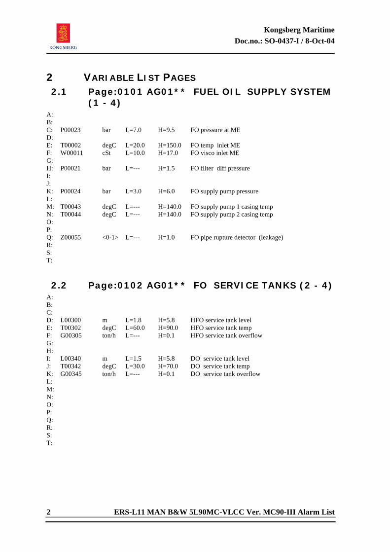
Kongsberg Maritime Doc.no.: SO-0437-I / 8-Oct-04
2 ERS-L11 MAN B&W 5L90MC-VLCC Ver. MC90-III Alarm List
2 VARIABLE LIST PAGES 2.1 Page:0101 AG01** FUEL OIL SUPPLY SYSTEM
(1 - 4) A: B: C: P00023 bar L=7.0 H=9.5 FO pressure at ME D: E: T00002 degC L=20.0 H=150.0 FO temp inlet ME F: W00011 cSt L=10.0 H=17.0 FO visco inlet ME G: H: P00021 bar L=--- H=1.5 FO filter diff pressure I: J: K: P00024 bar L=3.0 H=6.0 FO supply pump pressure L: M: T00043 degC L=--- H=140.0 FO supply pump 1 casing temp N: T00044 degC L=--- H=140.0 FO supply pump 2 casing temp O: P: Q: Z00055 <0-1> L=--- H=1.0 FO pipe rupture detector (leakage) R: S: T: 2.2 Page:0102 AG01** FO SERVICE TANKS (2 - 4)
A: B: C: D: L00300 m L=1.8 H=5.8 HFO service tank level E: T00302 degC L=60.0 H=90.0 HFO service tank temp F: G00305 ton/h L=--- H=0.1 HFO service tank overflow G: H: I: L00340 m L=1.5 H=5.8 DO service tank level J: T00342 degC L=30.0 H=70.0 DO service tank temp K: G00345 ton/h L=--- H=0.1 DO service tank overflow L: M: N: O: P: Q: R: S: T:
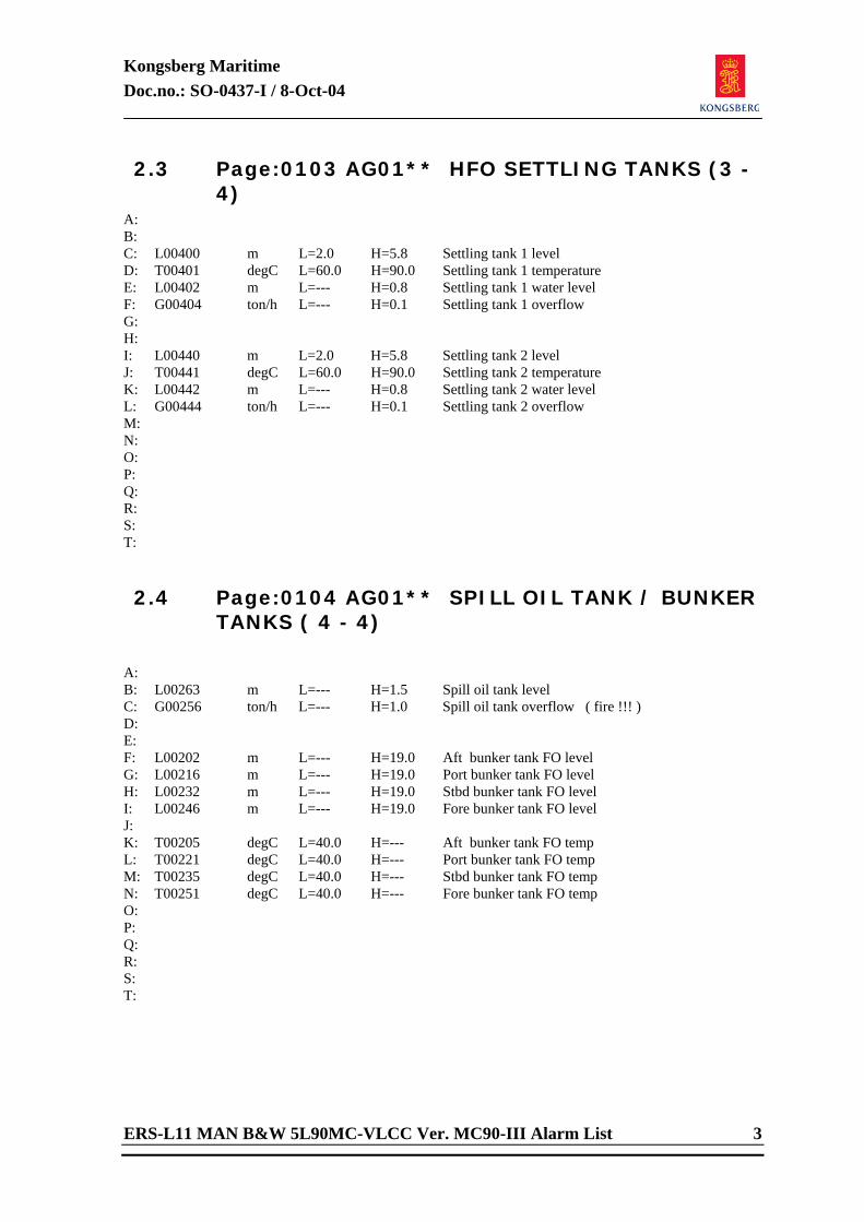
Kongsberg Maritime Doc.no.: SO-0437-I / 8-Oct-04
ERS-L11 MAN B&W 5L90MC-VLCC Ver. MC90-III Alarm List 3
2.3 Page:0103 AG01** HFO SETTLING TANKS (3 - 4)
A: B: C: L00400 m L=2.0 H=5.8 Settling tank 1 level D: T00401 degC L=60.0 H=90.0 Settling tank 1 temperature E: L00402 m L=--- H=0.8 Settling tank 1 water level F: G00404 ton/h L=--- H=0.1 Settling tank 1 overflow G: H: I: L00440 m L=2.0 H=5.8 Settling tank 2 level J: T00441 degC L=60.0 H=90.0 Settling tank 2 temperature K: L00442 m L=--- H=0.8 Settling tank 2 water level L: G00444 ton/h L=--- H=0.1 Settling tank 2 overflow M: N: O: P: Q: R: S: T: 2.4 Page:0104 AG01** SPILL OIL TANK / BUNKER
TANKS ( 4 - 4)
A: B: L00263 m L=--- H=1.5 Spill oil tank level C: G00256 ton/h L=--- H=1.0 Spill oil tank overflow ( fire !!! ) D: E: F: L00202 m L=--- H=19.0 Aft bunker tank FO level G: L00216 m L=--- H=19.0 Port bunker tank FO level H: L00232 m L=--- H=19.0 Stbd bunker tank FO level I: L00246 m L=--- H=19.0 Fore bunker tank FO level J: K: T00205 degC L=40.0 H=--- Aft bunker tank FO temp L: T00221 degC L=40.0 H=--- Port bunker tank FO temp M: T00235 degC L=40.0 H=--- Stbd bunker tank FO temp N: T00251 degC L=40.0 H=--- Fore bunker tank FO temp O: P: Q: R: S: T:
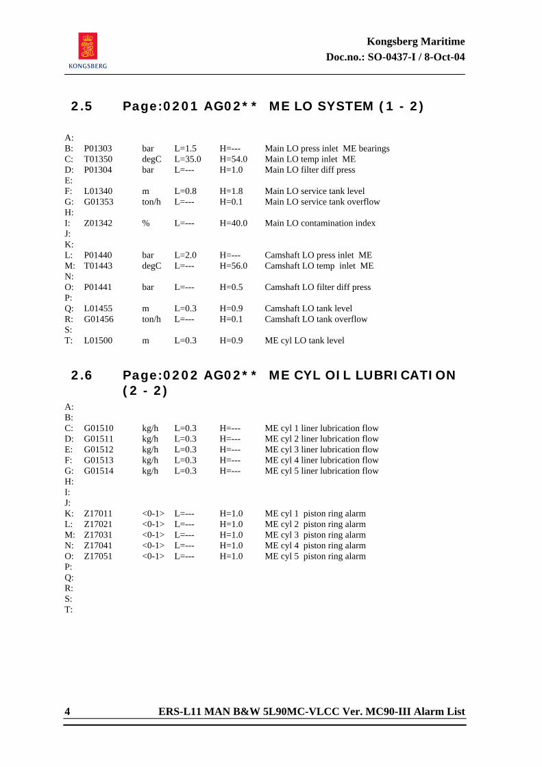
Kongsberg Maritime Doc.no.: SO-0437-I / 8-Oct-04
4 ERS-L11 MAN B&W 5L90MC-VLCC Ver. MC90-III Alarm List
2.5 Page:0201 AG02** ME LO SYSTEM (1 - 2)
A: B: P01303 bar L=1.5 H=--- Main LO press inlet ME bearings C: T01350 degC L=35.0 H=54.0 Main LO temp inlet ME D: P01304 bar L=--- H=1.0 Main LO filter diff press E: F: L01340 m L=0.8 H=1.8 Main LO service tank level G: G01353 ton/h L=--- H=0.1 Main LO service tank overflow H: I: Z01342 % L=--- H=40.0 Main LO contamination index J: K: L: P01440 bar L=2.0 H=--- Camshaft LO press inlet ME M: T01443 degC L=--- H=56.0 Camshaft LO temp inlet ME N: O: P01441 bar L=--- H=0.5 Camshaft LO filter diff press P: Q: L01455 m L=0.3 H=0.9 Camshaft LO tank level R: G01456 ton/h L=--- H=0.1 Camshaft LO tank overflow S: T: L01500 m L=0.3 H=0.9 ME cyl LO tank level 2.6 Page:0202 AG02** ME CYL OIL LUBRICATION
(2 - 2) A: B: C: G01510 kg/h L=0.3 H=--- ME cyl 1 liner lubrication flow D: G01511 kg/h L=0.3 H=--- ME cyl 2 liner lubrication flow E: G01512 kg/h L=0.3 H=--- ME cyl 3 liner lubrication flow F: G01513 kg/h L=0.3 H=--- ME cyl 4 liner lubrication flow G: G01514 kg/h L=0.3 H=--- ME cyl 5 liner lubrication flow H: I: J: K: Z17011 <0-1> L=--- H=1.0 ME cyl 1 piston ring alarm L: Z17021 <0-1> L=--- H=1.0 ME cyl 2 piston ring alarm M: Z17031 <0-1> L=--- H=1.0 ME cyl 3 piston ring alarm N: Z17041 <0-1> L=--- H=1.0 ME cyl 4 piston ring alarm O: Z17051 <0-1> L=--- H=1.0 ME cyl 5 piston ring alarm P: Q: R: S: T:
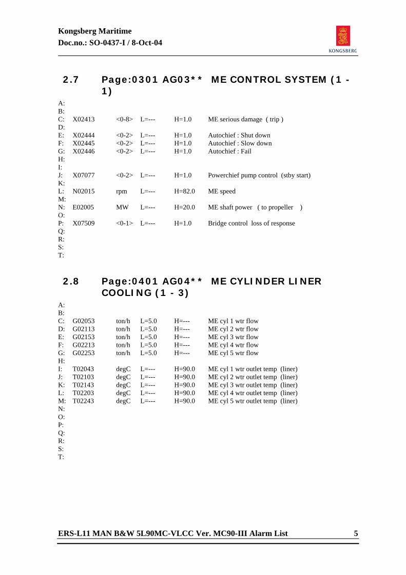
Kongsberg Maritime Doc.no.: SO-0437-I / 8-Oct-04
ERS-L11 MAN B&W 5L90MC-VLCC Ver. MC90-III Alarm List 5
2.7 Page:0301 AG03** ME CONTROL SYSTEM (1 - 1)
A: B: C: X02413 <0-8> L=--- H=1.0 ME serious damage ( trip ) D: E: X02444 <0-2> L=--- H=1.0 Autochief : Shut down F: X02445 <0-2> L=--- H=1.0 Autochief : Slow down G: X02446 <0-2> L=--- H=1.0 Autochief : Fail H: I: J: X07077 <0-2> L=--- H=1.0 Powerchief pump control (stby start) K: L: N02015 rpm L=--- H=82.0 ME speed M: N: E02005 MW L=--- H=20.0 ME shaft power ( to propeller ) O: P: X07509 <0-1> L=--- H=1.0 Bridge control loss of response Q: R: S: T: 2.8 Page:0401 AG04** ME CYLINDER LINER
COOLING (1 - 3) A: B: C: G02053 ton/h L=5.0 H=--- ME cyl 1 wtr flow D: G02113 ton/h L=5.0 H=--- ME cyl 2 wtr flow E: G02153 ton/h L=5.0 H=--- ME cyl 3 wtr flow F: G02213 ton/h L=5.0 H=--- ME cyl 4 wtr flow G: G02253 ton/h L=5.0 H=--- ME cyl 5 wtr flow H: I: T02043 degC L=--- H=90.0 ME cyl 1 wtr outlet temp (liner) J: T02103 degC L=--- H=90.0 ME cyl 2 wtr outlet temp (liner) K: T02143 degC L=--- H=90.0 ME cyl 3 wtr outlet temp (liner) L: T02203 degC L=--- H=90.0 ME cyl 4 wtr outlet temp (liner) M: T02243 degC L=--- H=90.0 ME cyl 5 wtr outlet temp (liner) N: O: P: Q: R: S: T:
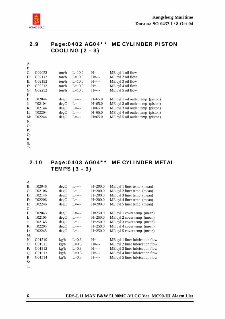
Kongsberg Maritime Doc.no.: SO-0437-I / 8-Oct-04
6 ERS-L11 MAN B&W 5L90MC-VLCC Ver. MC90-III Alarm List
2.9 Page:0402 AG04** ME CYLINDER PISTON COOLING (2 - 3)
A: B: C: G02052 ton/h L=10.0 H=--- ME cyl 1 oil flow D: G02112 ton/h L=10.0 H=--- ME cyl 2 oil flow E: G02152 ton/h L=10.0 H=--- ME cyl 3 oil flow F: G02212 ton/h L=10.0 H=--- ME cyl 4 oil flow G: G02252 ton/h L=10.0 H=--- ME cyl 5 oil flow H: I: T02044 degC L=--- H=65.0 ME cyl 1 oil outlet temp (piston) J: T02104 degC L=--- H=65.0 ME cyl 2 oil outlet temp (piston) K: T02144 degC L=--- H=65.0 ME cyl 3 oil outlet temp (piston) L: T02204 degC L=--- H=65.0 ME cyl 4 oil outlet temp (piston) M: T02244 degC L=--- H=65.0 ME cyl 5 oil outlet temp (piston) N: O: P: Q: R: S: T: 2.10 Page:0403 AG04** ME CYLINDER METAL
TEMPS (3 - 3)
A: B: T02046 degC L=--- H=200.0 ME cyl 1 liner temp (mean) C: T02106 degC L=--- H=200.0 ME cyl 2 liner temp (mean) D: T02146 degC L=--- H=200.0 ME cyl 3 liner temp (mean) E: T02206 degC L=--- H=200.0 ME cyl 4 liner temp (mean) F: T02246 degC L=--- H=200.0 ME cyl 5 liner temp (mean) G: H: T02045 degC L=--- H=250.0 ME cyl 1 cover temp (mean) I: T02105 degC L=--- H=250.0 ME cyl 2 cover temp (mean) J: T02145 degC L=--- H=250.0 ME cyl 3 cover temp (mean) K: T02205 degC L=--- H=250.0 ME cyl 4 cover temp (mean) L: T02245 degC L=--- H=250.0 ME cyl 5 cover temp (mean) M: N: G01510 kg/h L=0.3 H=--- ME cyl 1 liner lubrication flow O: G01511 kg/h L=0.3 H=--- ME cyl 2 liner lubrication flow P: G01512 kg/h L=0.3 H=--- ME cyl 3 liner lubrication flow Q: G01513 kg/h L=0.3 H=--- ME cyl 4 liner lubrication flow R: G01514 kg/h L=0.3 H=--- ME cyl 5 liner lubrication flow S: T:
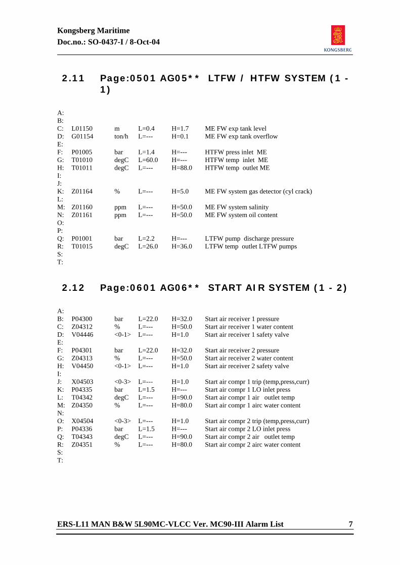
Kongsberg Maritime Doc.no.: SO-0437-I / 8-Oct-04
ERS-L11 MAN B&W 5L90MC-VLCC Ver. MC90-III Alarm List 7
2.11 Page:0501 AG05** LTFW / HTFW SYSTEM (1 - 1)
A: B: C: L01150 m L=0.4 H=1.7 ME FW exp tank level D: G01154 ton/h L=--- H=0.1 ME FW exp tank overflow E: F: P01005 bar L=1.4 H=--- HTFW press inlet ME G: T01010 degC L=60.0 H=--- HTFW temp inlet ME H: T01011 degC L=--- H=88.0 HTFW temp outlet ME I: J: K: Z01164 % L=--- H=5.0 ME FW system gas detector (cyl crack) L: M: Z01160 ppm L=--- H=50.0 ME FW system salinity N: Z01161 ppm L=--- H=50.0 ME FW system oil content O: P: Q: P01001 bar L=2.2 H=--- LTFW pump discharge pressure R: T01015 degC L=26.0 H=36.0 LTFW temp outlet LTFW pumps S: T: 2.12 Page:0601 AG06** START AIR SYSTEM (1 - 2)
A: B: P04300 bar L=22.0 H=32.0 Start air receiver 1 pressure C: Z04312 % L=--- H=50.0 Start air receiver 1 water content D: V04446 <0-1> L=--- H=1.0 Start air receiver 1 safety valve E: F: P04301 bar L=22.0 H=32.0 Start air receiver 2 pressure G: Z04313 % L=--- H=50.0 Start air receiver 2 water content H: V04450 <0-1> L=--- H=1.0 Start air receiver 2 safety valve I: J: X04503 <0-3> L=--- H=1.0 Start air compr 1 trip (temp,press,curr) K: P04335 bar L=1.5 H=--- Start air compr 1 LO inlet press L: T04342 degC L=--- H=90.0 Start air compr 1 air outlet temp M: Z04350 % L=--- H=80.0 Start air compr 1 airc water content N: O: X04504 <0-3> L=--- H=1.0 Start air compr 2 trip (temp,press,curr) P: P04336 bar L=1.5 H=--- Start air compr 2 LO inlet press Q: T04343 degC L=--- H=90.0 Start air compr 2 air outlet temp R: Z04351 % L=--- H=80.0 Start air compr 2 airc water content S: T:
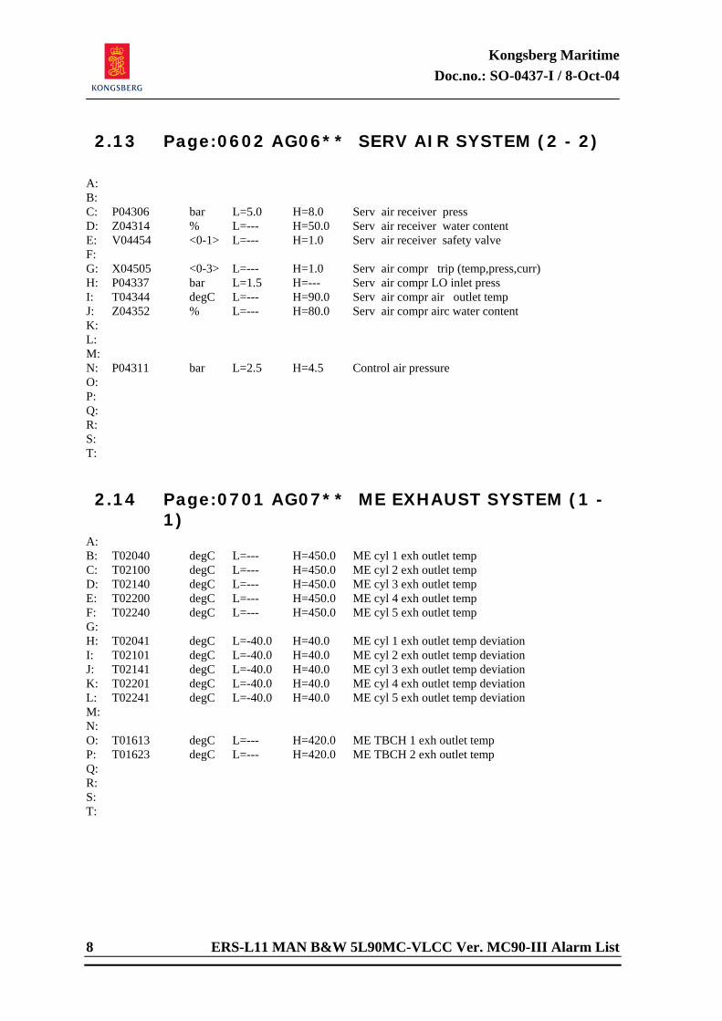
Kongsberg Maritime Doc.no.: SO-0437-I / 8-Oct-04
8 ERS-L11 MAN B&W 5L90MC-VLCC Ver. MC90-III Alarm List
2.13 Page:0602 AG06** SERV AIR SYSTEM (2 - 2)
A: B: C: P04306 bar L=5.0 H=8.0 Serv air receiver press D: Z04314 % L=--- H=50.0 Serv air receiver water content E: V04454 <0-1> L=--- H=1.0 Serv air receiver safety valve F: G: X04505 <0-3> L=--- H=1.0 Serv air compr trip (temp,press,curr) H: P04337 bar L=1.5 H=--- Serv air compr LO inlet press I: T04344 degC L=--- H=90.0 Serv air compr air outlet temp J: Z04352 % L=--- H=80.0 Serv air compr airc water content K: L: M: N: P04311 bar L=2.5 H=4.5 Control air pressure O: P: Q: R: S: T: 2.14 Page:0701 AG07** ME EXHAUST SYSTEM (1 -
1) A: B: T02040 degC L=--- H=450.0 ME cyl 1 exh outlet temp C: T02100 degC L=--- H=450.0 ME cyl 2 exh outlet temp D: T02140 degC L=--- H=450.0 ME cyl 3 exh outlet temp E: T02200 degC L=--- H=450.0 ME cyl 4 exh outlet temp F: T02240 degC L=--- H=450.0 ME cyl 5 exh outlet temp G: H: T02041 degC L=-40.0 H=40.0 ME cyl 1 exh outlet temp deviation I: T02101 degC L=-40.0 H=40.0 ME cyl 2 exh outlet temp deviation J: T02141 degC L=-40.0 H=40.0 ME cyl 3 exh outlet temp deviation K: T02201 degC L=-40.0 H=40.0 ME cyl 4 exh outlet temp deviation L: T02241 degC L=-40.0 H=40.0 ME cyl 5 exh outlet temp deviation M: N: O: T01613 degC L=--- H=420.0 ME TBCH 1 exh outlet temp P: T01623 degC L=--- H=420.0 ME TBCH 2 exh outlet temp Q: R: S: T:
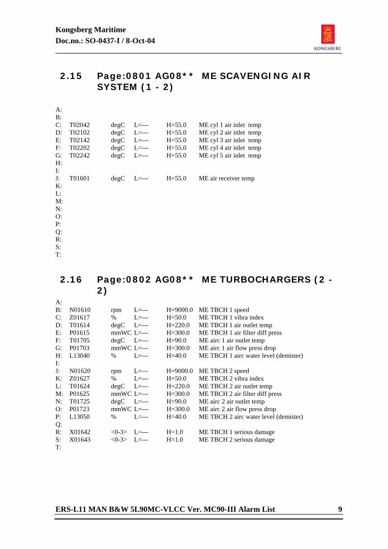
Kongsberg Maritime Doc.no.: SO-0437-I / 8-Oct-04
ERS-L11 MAN B&W 5L90MC-VLCC Ver. MC90-III Alarm List 9
2.15 Page:0801 AG08** ME SCAVENGING AIR SYSTEM (1 - 2)
A: B: C: T02042 degC L=--- H=55.0 ME cyl 1 air inlet temp D: T02102 degC L=--- H=55.0 ME cyl 2 air inlet temp E: T02142 degC L=--- H=55.0 ME cyl 3 air inlet temp F: T02202 degC L=--- H=55.0 ME cyl 4 air inlet temp G: T02242 degC L=--- H=55.0 ME cyl 5 air inlet temp H: I: J: T01601 degC L=--- H=55.0 ME air receiver temp K: L: M: N: O: P: Q: R: S: T: 2.16 Page:0802 AG08** ME TURBOCHARGERS (2 -
2) A: B: N01610 rpm L=--- H=9000.0 ME TBCH 1 speed C: Z01617 % L=--- H=50.0 ME TBCH 1 vibra index D: T01614 degC L=--- H=220.0 ME TBCH 1 air outlet temp E: P01615 mmWC L=--- H=300.0 ME TBCH 1 air filter diff press F: T01705 degC L=--- H=90.0 ME airc 1 air outlet temp G: P01703 mmWC L=--- H=300.0 ME airc 1 air flow press drop H: L13040 % L=--- H=40.0 ME TBCH 1 airc water level (demister) I: J: N01620 rpm L=--- H=9000.0 ME TBCH 2 speed K: Z01627 % L=--- H=50.0 ME TBCH 2 vibra index L: T01624 degC L=--- H=220.0 ME TBCH 2 air outlet temp M: P01625 mmWC L=--- H=300.0 ME TBCH 2 air filter diff press N: T01725 degC L=--- H=90.0 ME airc 2 air outlet temp O: P01723 mmWC L=--- H=300.0 ME airc 2 air flow press drop P: L13050 % L=--- H=40.0 ME TBCH 2 airc water level (demister) Q: R: X01642 <0-3> L=--- H=1.0 ME TBCH 1 serious damage S: X01643 <0-3> L=--- H=1.0 ME TBCH 2 serious damage T:
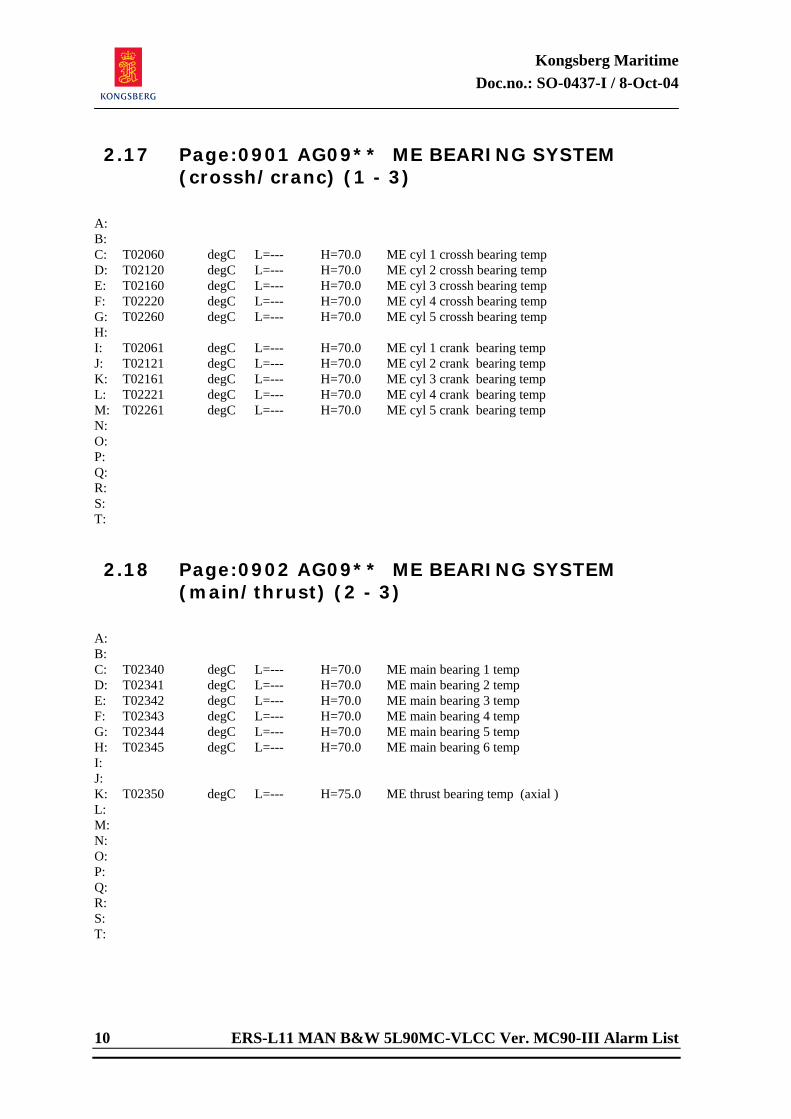
Kongsberg Maritime Doc.no.: SO-0437-I / 8-Oct-04
10 ERS-L11 MAN B&W 5L90MC-VLCC Ver. MC90-III Alarm List
2.17 Page:0901 AG09** ME BEARING SYSTEM (crossh/cranc) (1 - 3)
A: B: C: T02060 degC L=--- H=70.0 ME cyl 1 crossh bearing temp D: T02120 degC L=--- H=70.0 ME cyl 2 crossh bearing temp E: T02160 degC L=--- H=70.0 ME cyl 3 crossh bearing temp F: T02220 degC L=--- H=70.0 ME cyl 4 crossh bearing temp G: T02260 degC L=--- H=70.0 ME cyl 5 crossh bearing temp H: I: T02061 degC L=--- H=70.0 ME cyl 1 crank bearing temp J: T02121 degC L=--- H=70.0 ME cyl 2 crank bearing temp K: T02161 degC L=--- H=70.0 ME cyl 3 crank bearing temp L: T02221 degC L=--- H=70.0 ME cyl 4 crank bearing temp M: T02261 degC L=--- H=70.0 ME cyl 5 crank bearing temp N: O: P: Q: R: S: T: 2.18 Page:0902 AG09** ME BEARING SYSTEM
(main/thrust) (2 - 3)
A: B: C: T02340 degC L=--- H=70.0 ME main bearing 1 temp D: T02341 degC L=--- H=70.0 ME main bearing 2 temp E: T02342 degC L=--- H=70.0 ME main bearing 3 temp F: T02343 degC L=--- H=70.0 ME main bearing 4 temp G: T02344 degC L=--- H=70.0 ME main bearing 5 temp H: T02345 degC L=--- H=70.0 ME main bearing 6 temp I: J: K: T02350 degC L=--- H=75.0 ME thrust bearing temp (axial ) L: M: N: O: P: Q: R: S: T:
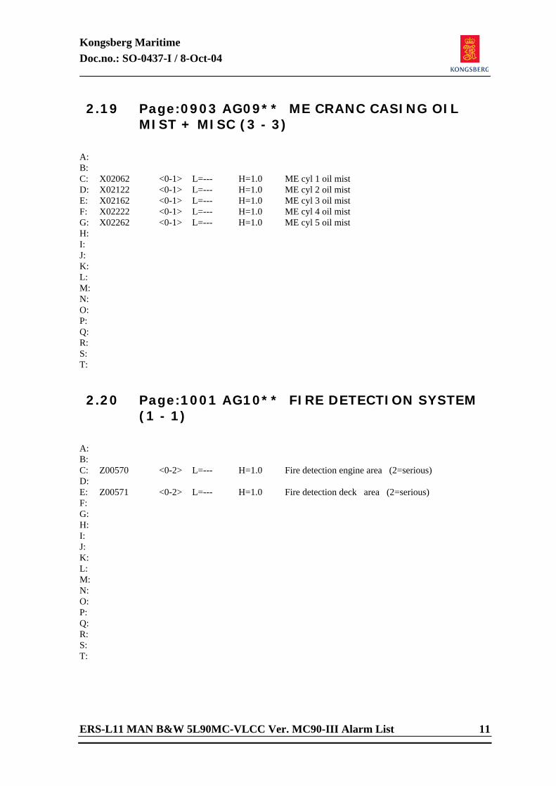
Kongsberg Maritime Doc.no.: SO-0437-I / 8-Oct-04
ERS-L11 MAN B&W 5L90MC-VLCC Ver. MC90-III Alarm List 11
2.19 Page:0903 AG09** ME CRANC CASING OIL MIST + MISC (3 - 3)
A: B: C: X02062 <0-1> L=--- H=1.0 ME cyl 1 oil mist D: X02122 <0-1> L=--- H=1.0 ME cyl 2 oil mist E: X02162 <0-1> L=--- H=1.0 ME cyl 3 oil mist F: X02222 <0-1> L=--- H=1.0 ME cyl 4 oil mist G: X02262 <0-1> L=--- H=1.0 ME cyl 5 oil mist H: I: J: K: L: M: N: O: P: Q: R: S: T: 2.20 Page:1001 AG10** FIRE DETECTION SYSTEM
(1 - 1)
A: B: C: Z00570 <0-2> L=--- H=1.0 Fire detection engine area (2=serious) D: E: Z00571 <0-2> L=--- H=1.0 Fire detection deck area (2=serious) F: G: H: I: J: K: L: M: N: O: P: Q: R: S: T:
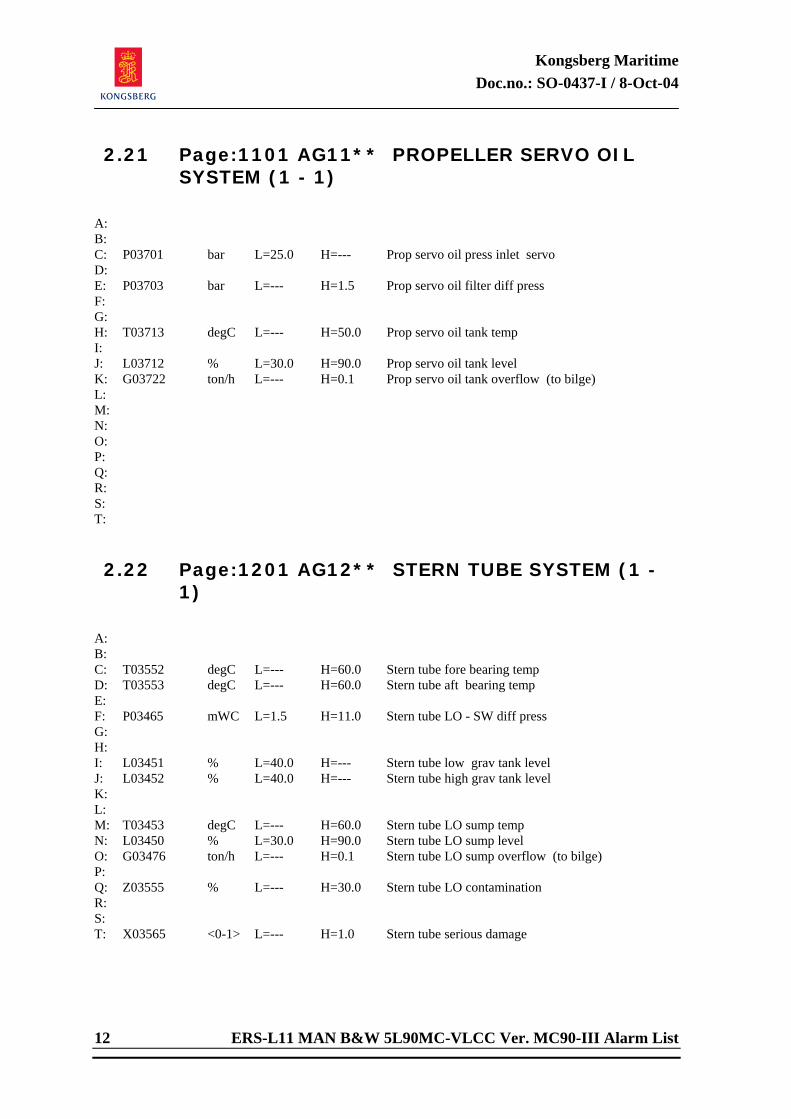
Kongsberg Maritime Doc.no.: SO-0437-I / 8-Oct-04
12 ERS-L11 MAN B&W 5L90MC-VLCC Ver. MC90-III Alarm List
2.21 Page:1101 AG11** PROPELLER SERVO OIL SYSTEM (1 - 1)
A: B: C: P03701 bar L=25.0 H=--- Prop servo oil press inlet servo D: E: P03703 bar L=--- H=1.5 Prop servo oil filter diff press F: G: H: T03713 degC L=--- H=50.0 Prop servo oil tank temp I: J: L03712 % L=30.0 H=90.0 Prop servo oil tank level K: G03722 ton/h L=--- H=0.1 Prop servo oil tank overflow (to bilge) L: M: N: O: P: Q: R: S: T: 2.22 Page:1201 AG12** STERN TUBE SYSTEM (1 -
1)
A: B: C: T03552 degC L=--- H=60.0 Stern tube fore bearing temp D: T03553 degC L=--- H=60.0 Stern tube aft bearing temp E: F: P03465 mWC L=1.5 H=11.0 Stern tube LO - SW diff press G: H: I: L03451 % L=40.0 H=--- Stern tube low grav tank level J: L03452 % L=40.0 H=--- Stern tube high grav tank level K: L: M: T03453 degC L=--- H=60.0 Stern tube LO sump temp N: L03450 % L=30.0 H=90.0 Stern tube LO sump level O: G03476 ton/h L=--- H=0.1 Stern tube LO sump overflow (to bilge) P: Q: Z03555 % L=--- H=30.0 Stern tube LO contamination R: S: T: X03565 <0-1> L=--- H=1.0 Stern tube serious damage
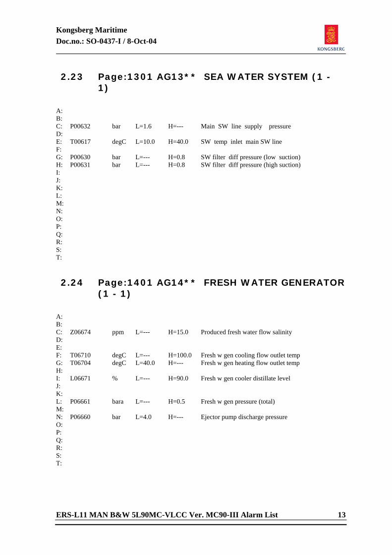
Kongsberg Maritime Doc.no.: SO-0437-I / 8-Oct-04
ERS-L11 MAN B&W 5L90MC-VLCC Ver. MC90-III Alarm List 13
2.23 Page:1301 AG13** SEA WATER SYSTEM (1 - 1)
A: B: C: P00632 bar L=1.6 H=--- Main SW line supply pressure D: E: T00617 degC L=10.0 H=40.0 SW temp inlet main SW line F: G: P00630 bar L=--- H=0.8 SW filter diff pressure (low suction) H: P00631 bar L=--- H=0.8 SW filter diff pressure (high suction) I: J: K: L: M: N: O: P: Q: R: S: T: 2.24 Page:1401 AG14** FRESH WATER GENERATOR
(1 - 1)
A: B: C: Z06674 ppm L=--- H=15.0 Produced fresh water flow salinity D: E: F: T06710 degC L=--- H=100.0 Fresh w gen cooling flow outlet temp G: T06704 degC L=40.0 H=--- Fresh w gen heating flow outlet temp H: I: L06671 % L=--- H=90.0 Fresh w gen cooler distillate level J: K: L: P06661 bara L=--- H=0.5 Fresh w gen pressure (total) M: N: P06660 bar L=4.0 H=--- Ejector pump discharge pressure O: P: Q: R: S: T:
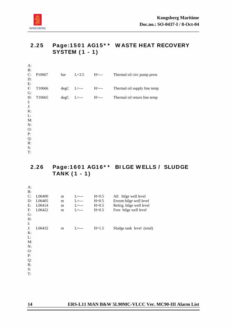
Kongsberg Maritime Doc.no.: SO-0437-I / 8-Oct-04
14 ERS-L11 MAN B&W 5L90MC-VLCC Ver. MC90-III Alarm List
2.25 Page:1501 AG15** WASTE HEAT RECOVERY SYSTEM (1 - 1)
A: B: C: P10667 bar L=3.5 H=--- Thermal oil circ pump press D: E: F: T10666 degC L=--- H=--- Thermal oil supply line temp G: H: T10665 degC L=--- H=--- Thermal oil return line temp I: J: K: L: M: N: O: P: Q: R: S: T: 2.26 Page:1601 AG16** BILGE WELLS / SLUDGE
TANK (1 - 1)
A: B: C: L06400 m L=--- H=0.5 Aft bilge well level D: L06405 m L=--- H=0.5 Eroom bilge well level E: L06414 m L=--- H=0.5 Refrig. bilge well level F: L06422 m L=--- H=0.5 Fore bilge well level G: H: I: J: L06432 m L=--- H=1.5 Sludge tank level (total) K: L: M: N: O: P: Q: R: S: T:
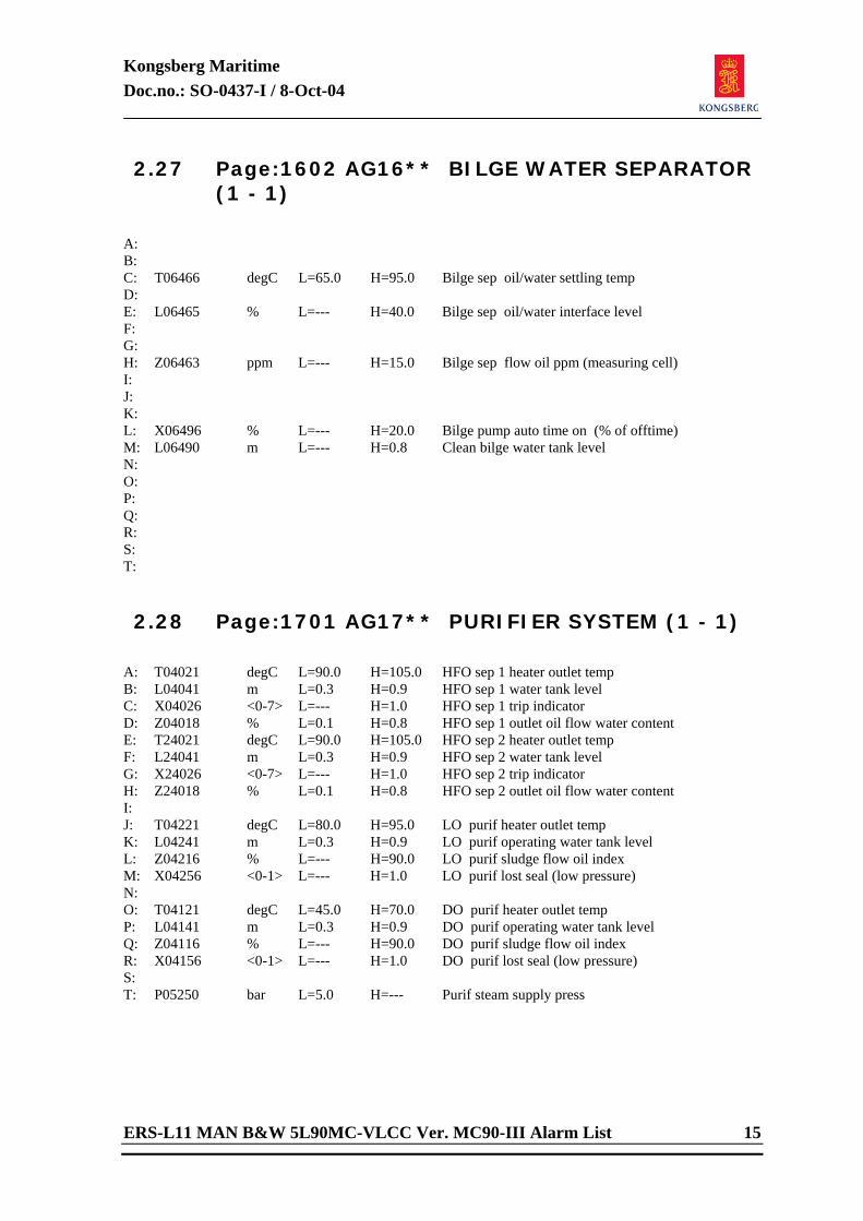
Kongsberg Maritime Doc.no.: SO-0437-I / 8-Oct-04
ERS-L11 MAN B&W 5L90MC-VLCC Ver. MC90-III Alarm List 15
2.27 Page:1602 AG16** BILGE WATER SEPARATOR (1 - 1)
A: B: C: T06466 degC L=65.0 H=95.0 Bilge sep oil/water settling temp D: E: L06465 % L=--- H=40.0 Bilge sep oil/water interface level F: G: H: Z06463 ppm L=--- H=15.0 Bilge sep flow oil ppm (measuring cell) I: J: K: L: X06496 % L=--- H=20.0 Bilge pump auto time on (% of offtime) M: L06490 m L=--- H=0.8 Clean bilge water tank level N: O: P: Q: R: S: T: 2.28 Page:1701 AG17** PURIFIER SYSTEM (1 - 1)
A: T04021 degC L=90.0 H=105.0 HFO sep 1 heater outlet temp B: L04041 m L=0.3 H=0.9 HFO sep 1 water tank level C: X04026 <0-7> L=--- H=1.0 HFO sep 1 trip indicator D: Z04018 % L=0.1 H=0.8 HFO sep 1 outlet oil flow water content E: T24021 degC L=90.0 H=105.0 HFO sep 2 heater outlet temp F: L24041 m L=0.3 H=0.9 HFO sep 2 water tank level G: X24026 <0-7> L=--- H=1.0 HFO sep 2 trip indicator H: Z24018 % L=0.1 H=0.8 HFO sep 2 outlet oil flow water content I: J: T04221 degC L=80.0 H=95.0 LO purif heater outlet temp K: L04241 m L=0.3 H=0.9 LO purif operating water tank level L: Z04216 % L=--- H=90.0 LO purif sludge flow oil index M: X04256 <0-1> L=--- H=1.0 LO purif lost seal (low pressure) N: O: T04121 degC L=45.0 H=70.0 DO purif heater outlet temp P: L04141 m L=0.3 H=0.9 DO purif operating water tank level Q: Z04116 % L=--- H=90.0 DO purif sludge flow oil index R: X04156 <0-1> L=--- H=1.0 DO purif lost seal (low pressure) S: T: P05250 bar L=5.0 H=--- Purif steam supply press
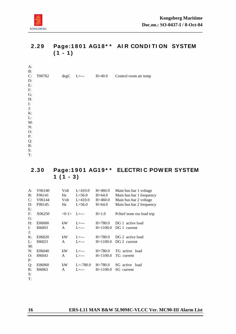
Kongsberg Maritime Doc.no.: SO-0437-I / 8-Oct-04
16 ERS-L11 MAN B&W 5L90MC-VLCC Ver. MC90-III Alarm List
2.29 Page:1801 AG18** AIR CONDITION SYSTEM (1 - 1)
A: B: C: T00762 degC L=--- H=40.0 Control room air temp D: E: F: G: H: I: J: K: L: M: N: O: P: Q: R: S: T: 2.30 Page:1901 AG19** ELECTRIC POWER SYSTEM
1 (1 - 3)
A: V06140 Volt L=410.0 H=460.0 Main bus bar 1 voltage B: F06141 Hz L=56.0 H=64.0 Main bus bar 1 frequency C: V06144 Volt L=410.0 H=460.0 Main bus bar 2 voltage D: F06145 Hz L=56.0 H=64.0 Main bus bar 2 frequency E: F: X06250 <0-1> L=--- H=1.0 Pchief none ess load trip G: H: E06000 kW L=--- H=780.0 DG 1 active load I: I06003 A L=--- H=1100.0 DG 1 current J: K: E06020 kW L=--- H=780.0 DG 2 active load L: I06023 A L=--- H=1100.0 DG 2 current M: N: E06040 kW L=--- H=780.0 TG active load O: I06043 A L=--- H=1100.0 TG current P: Q: E06060 kW L=-780.0 H=780.0 SG active load R: I06063 A L=--- H=1100.0 SG current S: T:
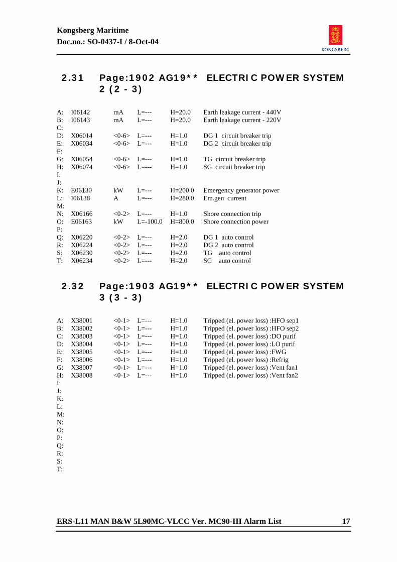
Kongsberg Maritime Doc.no.: SO-0437-I / 8-Oct-04
ERS-L11 MAN B&W 5L90MC-VLCC Ver. MC90-III Alarm List 17
2.31 Page:1902 AG19** ELECTRIC POWER SYSTEM 2 (2 - 3)
A: I06142 mA L=--- H=20.0 Earth leakage current - 440V B: I06143 mA L=--- H=20.0 Earth leakage current - 220V C: D: X06014 <0-6> L=--- H=1.0 DG 1 circuit breaker trip E: X06034 <0-6> L=--- H=1.0 DG 2 circuit breaker trip F: G: X06054 <0-6> L=--- H=1.0 TG circuit breaker trip H: X06074 <0-6> L=--- H=1.0 SG circuit breaker trip I: J: K: E06130 kW L=--- H=200.0 Emergency generator power L: I06138 A L=--- H=280.0 Em.gen current M: N: X06166 <0-2> L=--- H=1.0 Shore connection trip O: E06163 kW L=-100.0 H=800.0 Shore connection power P: Q: X06220 <0-2> L=--- H=2.0 DG 1 auto control R: X06224 <0-2> L=--- H=2.0 DG 2 auto control S: X06230 <0-2> L=--- H=2.0 TG auto control T: X06234 <0-2> L=--- H=2.0 SG auto control 2.32 Page:1903 AG19** ELECTRIC POWER SYSTEM
3 (3 - 3)
A: X38001 <0-1> L=--- H=1.0 Tripped (el. power loss) :HFO sep1 B: X38002 <0-1> L=--- H=1.0 Tripped (el. power loss) :HFO sep2 C: X38003 <0-1> L=--- H=1.0 Tripped (el. power loss) :DO purif D: X38004 <0-1> L=--- H=1.0 Tripped (el. power loss) :LO purif E: X38005 <0-1> L=--- H=1.0 Tripped (el. power loss) :FWG F: X38006 <0-1> L=--- H=1.0 Tripped (el. power loss) :Refrig G: X38007 <0-1> L=--- H=1.0 Tripped (el. power loss) :Vent fan1 H: X38008 <0-1> L=--- H=1.0 Tripped (el. power loss) :Vent fan2 I: J: K: L: M: N: O: P: Q: R: S: T:
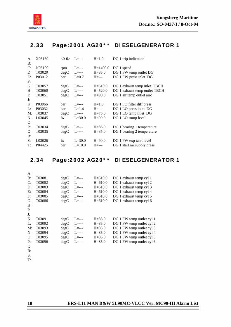
Kongsberg Maritime Doc.no.: SO-0437-I / 8-Oct-04
18 ERS-L11 MAN B&W 5L90MC-VLCC Ver. MC90-III Alarm List
2.33 Page:2001 AG20** DIESELGENERATOR 1
A: X03160 <0-6> L=--- H=1.0 DG 1 trip indication B: C: N03100 rpm L=--- H=1400.0 DG 1 speed D: T03020 degC L=--- H=85.0 DG 1 FW temp outlet DG E: P03012 bar L=0.7 H=--- DG 1 FW press inlet DG F: G: T03057 degC L=--- H=610.0 DG 1 exhaust temp inlet TBCH H: T03060 degC L=--- H=520.0 DG 1 exhaust temp outlet TBCH I: T03051 degC L=--- H=90.0 DG 1 air temp outlet airc J: K: P03066 bar L=--- H=1.0 DG 1 FO filter diff press L: P03032 bar L=1.4 H=--- DG 1 LO press inlet DG M: T03037 degC L=--- H=75.0 DG 1 LO temp inlet DG N: L03045 % L=30.0 H=90.0 DG 1 LO sump level O: P: T03034 degC L=--- H=85.0 DG 1 bearing 1 temperature Q: T03035 degC L=--- H=85.0 DG 1 bearing 2 temperature R: S: L03026 % L=30.0 H=90.0 DG 1 FW exp tank level T: P04425 bar L=10.0 H=--- DG 1 start air supply press 2.34 Page:2002 AG20** DIESELGENERATOR 1
A: B: T03081 degC L=--- H=610.0 DG 1 exhaust temp cyl 1 C: T03082 degC L=--- H=610.0 DG 1 exhaust temp cyl 2 D: T03083 degC L=--- H=610.0 DG 1 exhaust temp cyl 3 E: T03084 degC L=--- H=610.0 DG 1 exhaust temp cyl 4 F: T03085 degC L=--- H=610.0 DG 1 exhaust temp cyl 5 G: T03086 degC L=--- H=610.0 DG 1 exhaust temp cyl 6 H: I: J: K: T03091 degC L=--- H=85.0 DG 1 FW temp outlet cyl 1 L: T03092 degC L=--- H=85.0 DG 1 FW temp outlet cyl 2 M: T03093 degC L=--- H=85.0 DG 1 FW temp outlet cyl 3 N: T03094 degC L=--- H=85.0 DG 1 FW temp outlet cyl 4 O: T03095 degC L=--- H=85.0 DG 1 FW temp outlet cyl 5 P: T03096 degC L=--- H=85.0 DG 1 FW temp outlet cyl 6 Q: R: S: T:
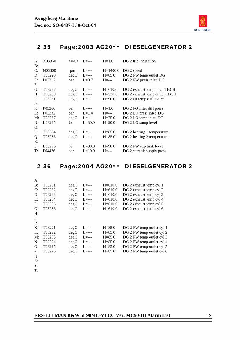
Kongsberg Maritime Doc.no.: SO-0437-I / 8-Oct-04
ERS-L11 MAN B&W 5L90MC-VLCC Ver. MC90-III Alarm List 19
2.35 Page:2003 AG20** DIESELGENERATOR 2
A: X03360 <0-6> L=--- H=1.0 DG 2 trip indication B: C: N03300 rpm L=--- H=1400.0 DG 2 speed D: T03220 degC L=--- H=85.0 DG 2 FW temp outlet DG E: P03212 bar L=0.7 H=--- DG 2 FW press inlet DG F: G: T03257 degC L=--- H=610.0 DG 2 exhaust temp inlet TBCH H: T03260 degC L=--- H=520.0 DG 2 exhaust temp outlet TBCH I: T03251 degC L=--- H=90.0 DG 2 air temp outlet airc J: K: P03266 bar L=--- H=1.0 DG 2 FO filter diff press L: P03232 bar L=1.4 H=--- DG 2 LO press inlet DG M: T03237 degC L=--- H=75.0 DG 2 LO temp inlet DG N: L03245 % L=30.0 H=90.0 DG 2 LO sump level O: P: T03234 degC L=--- H=85.0 DG 2 bearing 1 temperature Q: T03235 degC L=--- H=85.0 DG 2 bearing 2 temperature R: S: L03226 % L=30.0 H=90.0 DG 2 FW exp tank level T: P04426 bar L=10.0 H=--- DG 2 start air supply press 2.36 Page:2004 AG20** DIESELGENERATOR 2
A: B: T03281 degC L=--- H=610.0 DG 2 exhaust temp cyl 1 C: T03282 degC L=--- H=610.0 DG 2 exhaust temp cyl 2 D: T03283 degC L=--- H=610.0 DG 2 exhaust temp cyl 3 E: T03284 degC L=--- H=610.0 DG 2 exhaust temp cyl 4 F: T03285 degC L=--- H=610.0 DG 2 exhaust temp cyl 5 G: T03286 degC L=--- H=610.0 DG 2 exhaust temp cyl 6 H: I: J: K: T03291 degC L=--- H=85.0 DG 2 FW temp outlet cyl 1 L: T03292 degC L=--- H=85.0 DG 2 FW temp outlet cyl 2 M: T03293 degC L=--- H=85.0 DG 2 FW temp outlet cyl 3 N: T03294 degC L=--- H=85.0 DG 2 FW temp outlet cyl 4 O: T03295 degC L=--- H=85.0 DG 2 FW temp outlet cyl 5 P: T03296 degC L=--- H=85.0 DG 2 FW temp outlet cyl 6 Q: R: S: T:
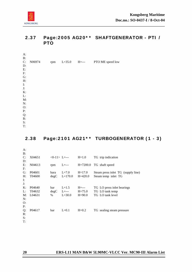
Kongsberg Maritime Doc.no.: SO-0437-I / 8-Oct-04
20 ERS-L11 MAN B&W 5L90MC-VLCC Ver. MC90-III Alarm List
2.37 Page:2005 AG20** SHAFTGENERATOR - PTI / PTO
A: B: C: N06974 rpm L=35.0 H=--- PTO ME speed low D: E: F: G: H: I: J: K: L: M: N: O: P: Q: R: S: T: 2.38 Page:2101 AG21** TURBOGENERATOR (1 - 3)
A: B: C: X04651 <0-11> L=--- H=1.0 TG trip indication D: E: N04613 rpm L=--- H=7200.0 TG shaft speed F: G: P04601 bara L=7.0 H=17.0 Steam press inlet TG (supply line) H: T04600 degC L=170.0 H=420.0 Steam temp inlet TG I: J: K: P04640 bar L=1.5 H=--- TG LO press inlet bearings L: T04632 degC L=--- H=75.0 TG LO tank temp M: L04631 % L=30.0 H=90.0 TG LO tank level N: O: P: Q: P04617 bar L=0.1 H=0.2 TG sealing steam pressure R: S: T:
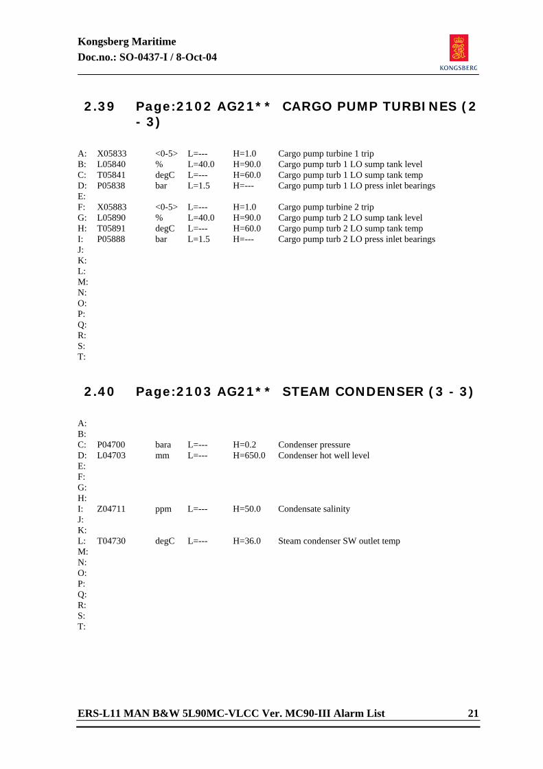
Kongsberg Maritime Doc.no.: SO-0437-I / 8-Oct-04
ERS-L11 MAN B&W 5L90MC-VLCC Ver. MC90-III Alarm List 21
2.39 Page:2102 AG21** CARGO PUMP TURBINES (2 - 3)
A: X05833 <0-5> L=--- H=1.0 Cargo pump turbine 1 trip B: L05840 % L=40.0 H=90.0 Cargo pump turb 1 LO sump tank level C: T05841 degC L=--- H=60.0 Cargo pump turb 1 LO sump tank temp D: P05838 bar L=1.5 H=--- Cargo pump turb 1 LO press inlet bearings E: F: X05883 <0-5> L=--- H=1.0 Cargo pump turbine 2 trip G: L05890 % L=40.0 H=90.0 Cargo pump turb 2 LO sump tank level H: T05891 degC L=--- H=60.0 Cargo pump turb 2 LO sump tank temp I: P05888 bar L=1.5 H=--- Cargo pump turb 2 LO press inlet bearings J: K: L: M: N: O: P: Q: R: S: T: 2.40 Page:2103 AG21** STEAM CONDENSER (3 - 3)
A: B: C: P04700 bara L=--- H=0.2 Condenser pressure D: L04703 mm L=--- H=650.0 Condenser hot well level E: F: G: H: I: Z04711 ppm L=--- H=50.0 Condensate salinity J: K: L: T04730 degC L=--- H=36.0 Steam condenser SW outlet temp M: N: O: P: Q: R: S: T:
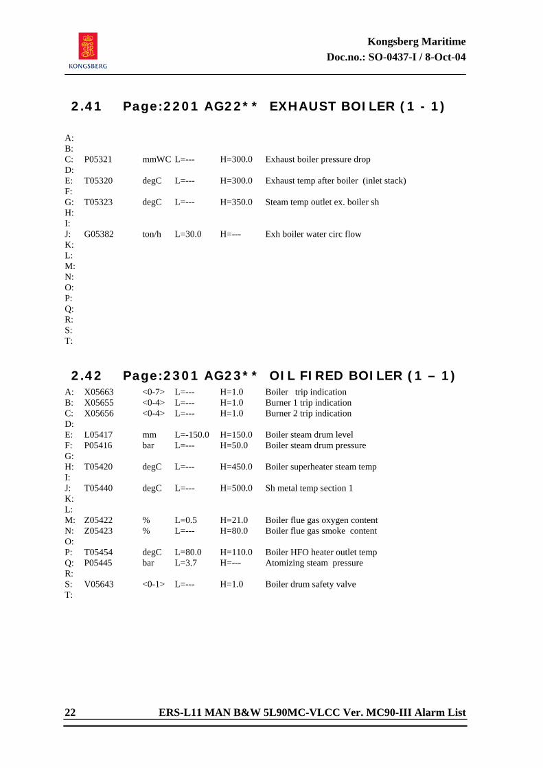
Kongsberg Maritime Doc.no.: SO-0437-I / 8-Oct-04
22 ERS-L11 MAN B&W 5L90MC-VLCC Ver. MC90-III Alarm List
2.41 Page:2201 AG22** EXHAUST BOILER (1 - 1)
A: B: C: P05321 mmWC L=--- H=300.0 Exhaust boiler pressure drop D: E: T05320 degC L=--- H=300.0 Exhaust temp after boiler (inlet stack) F: G: T05323 degC L=--- H=350.0 Steam temp outlet ex. boiler sh H: I: J: G05382 ton/h L=30.0 H=--- Exh boiler water circ flow K: L: M: N: O: P: Q: R: S: T: 2.42 Page:2301 AG23** OIL FIRED BOILER (1 – 1)
A: X05663 <0-7> L=--- H=1.0 Boiler trip indication B: X05655 <0-4> L=--- H=1.0 Burner 1 trip indication C: X05656 <0-4> L=--- H=1.0 Burner 2 trip indication D: E: L05417 mm L=-150.0 H=150.0 Boiler steam drum level F: P05416 bar L=--- H=50.0 Boiler steam drum pressure G: H: T05420 degC L=--- H=450.0 Boiler superheater steam temp I: J: T05440 degC L=--- H=500.0 Sh metal temp section 1 K: L: M: Z05422 % L=0.5 H=21.0 Boiler flue gas oxygen content N: Z05423 % L=--- H=80.0 Boiler flue gas smoke content O: P: T05454 degC L=80.0 H=110.0 Boiler HFO heater outlet temp Q: P05445 bar L=3.7 H=--- Atomizing steam pressure R: S: V05643 <0-1> L=--- H=1.0 Boiler drum safety valve T:

Kongsberg Maritime Doc.no.: SO-0437-I / 8-Oct-04
ERS-L11 MAN B&W 5L90MC-VLCC Ver. MC90-III Alarm List 23
2.43 Page:2401 AG24** STEAM GENERATOR (1 - 1)
A: B: X05627 <0-1> L=--- H=1.0 Feedw pump trip indication C: D: E: P05001 bar L=7.0 H=15.0 Stgen steam pressure F: L05003 mm L=-150.0 H=150.0 Stgen water level G: H: V05101 <0-1> L=--- H=1.0 Stgen safety valve I: V05102 <0-1> L=--- H=1.0 Main line safety valve J: V05106 <0-1> L=--- H=1.0 Steam dump valve K: L: M: L05150 m L=1.0 H=2.8 Feed water tank level N: G05152 ton/h L=--- H=0.1 Feed water tank overflow O: P: Q: R: S: T: 2.44 Page:2501 AG25** REFRIGERATION SYSTEM
(1 - 2)
A: B: T06554 degC L=-35.0 H=-25.0 Refrig cargo hold air temp C: T16554 degC L=2.0 H=8.0 Refrig prov store air temp D: E: F: X06524 <0-5> L=--- H=1.0 Refrig comp trip indication G: E06533 kW L=--- H=230.0 Refrig comp electric power H: I: P06530 bar L=-0.7 H=--- Refrig comp suction press J: P06527 bar L=--- H=15.0 Refrig comp discharge press K: T06532 degC L=--- H=90.0 Refrig comp discharge temp L: M: P06571 bar L=1.5 H=--- Refrig comp LO inlet diff press N: O: P: Q: R: S: T:
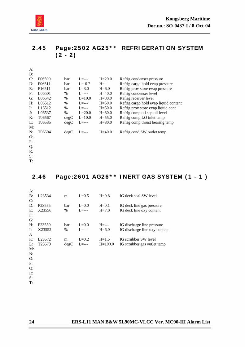
Kongsberg Maritime Doc.no.: SO-0437-I / 8-Oct-04
24 ERS-L11 MAN B&W 5L90MC-VLCC Ver. MC90-III Alarm List
2.45 Page:2502 AG25** REFRIGERATION SYSTEM (2 - 2)
A: B: C: P06500 bar L=--- H=29.0 Refrig condenser pressure D: P06511 bar L=-0.7 H=--- Refrig cargo hold evap pressure E: P16511 bar L=3.0 H=6.0 Refrig prov store evap pressure F: L06501 % L=--- H=40.0 Refrig condenser level G: L06542 % L=10.0 H=80.0 Refrig receiver level H: L06512 % L=--- H=50.0 Refrig cargo hold evap liquid content I: L16512 % L=--- H=50.0 Refrig prov store evap liquid cont J: L06537 % L=20.0 H=80.0 Refrig comp oil sep oil level K: T06567 degC L=10.0 H=55.0 Refrig comp LO inlet temp L: T06535 degC L=--- H=80.0 Refrig comp thrust bearing temp M: N: T06504 degC L=--- H=40.0 Refrig cond SW outlet temp O: P: Q: R: S: T: 2.46 Page:2601 AG26** INERT GAS SYSTEM (1 - 1 )
A: B: L23534 m L=0.5 H=0.8 IG deck seal SW level C: D: P23555 bar L=0.0 H=0.1 IG deck line gas pressure E: X23556 % L=--- H=7.0 IG deck line oxy content F: G: H: P23550 bar L=0.0 H=--- IG discharge line pressure I: X23552 % L=--- H=6.0 IG discharge line oxy content J: K: L23572 m L=0.2 H=1.5 IG scrubber SW level L: T23573 degC L=--- H=100.0 IG scrubber gas outlet temp M: N: O: P: Q: R: S: T:
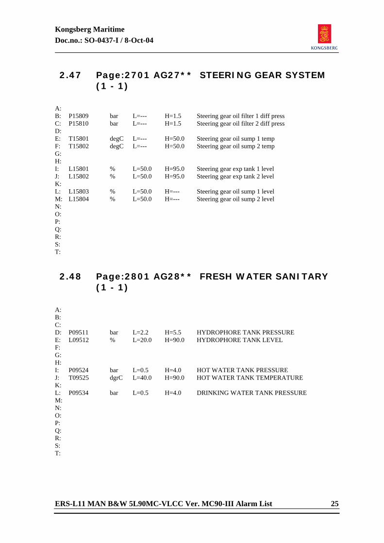
Kongsberg Maritime Doc.no.: SO-0437-I / 8-Oct-04
ERS-L11 MAN B&W 5L90MC-VLCC Ver. MC90-III Alarm List 25
2.47 Page:2701 AG27** STEERING GEAR SYSTEM (1 - 1)
A: B: P15809 bar L=--- H=1.5 Steering gear oil filter 1 diff press C: P15810 bar L=--- H=1.5 Steering gear oil filter 2 diff press D: E: T15801 degC L=--- H=50.0 Steering gear oil sump 1 temp F: T15802 degC L=--- H=50.0 Steering gear oil sump 2 temp G: H: I: L15801 % L=50.0 H=95.0 Steering gear exp tank 1 level J: L15802 % L=50.0 H=95.0 Steering gear exp tank 2 level K: L: L15803 % L=50.0 H=--- Steering gear oil sump 1 level M: L15804 % L=50.0 H=--- Steering gear oil sump 2 level N: O: P: Q: R: S: T: 2.48 Page:2801 AG28** FRESH WATER SANITARY
(1 - 1)
A: B: C: D: P09511 bar L=2.2 H=5.5 HYDROPHORE TANK PRESSURE E: L09512 % L=20.0 H=90.0 HYDROPHORE TANK LEVEL F: G: H: I: P09524 bar L=0.5 H=4.0 HOT WATER TANK PRESSURE J: T09525 dgrC L=40.0 H=90.0 HOT WATER TANK TEMPERATURE K: L: P09534 bar L=0.5 H=4.0 DRINKING WATER TANK PRESSURE M: N: O: P: Q: R: S: T:
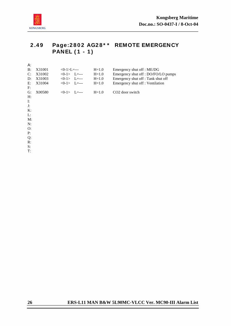
Kongsberg Maritime Doc.no.: SO-0437-I / 8-Oct-04
26 ERS-L11 MAN B&W 5L90MC-VLCC Ver. MC90-III Alarm List
2.49 Page:2802 AG28** REMOTE EMERGENCY PANEL (1 - 1)
A: B: X31001 <0-1>L=--- H=1.0 Emergency shut off : ME/DG C: X31002 <0-1> L=--- H=1.0 Emergency shut off : DO/FO/LO pumps D: X31003 <0-1> L=--- H=1.0 Emergency shut off : Tank shut off E: X31004 <0-1> L=--- H=1.0 Emergency shut off : Ventilation F: G: X00580 <0-1> L=--- H=1.0 CO2 door switch H: I: J: K: L: M: N: O: P: Q: R: S: T:
Kongsberg Maritime Doc.no.: SO-0622-H1 / 2-May-05
ERS-L11 MAN B&W 5L90MC-VLCC Ver.MC90-III User's Manual
Engine Room Simulator
ERS-L11 MAN B&W 5L90MC-VLCC Version MC90-III
USER'S MANUAL
Appendix D
Malfunction List
Doc.no.: SO-0438

Kongsberg Maritime Doc.no.: SO-0438-I / 8-Oct-04
ERS-L11 MAN B&W 5L90MC-VLCC Ver. MC90-III Malfunction List
Engine Room Simulator
ERS-L11 MAN B&W 5L90MC-VLCC Version MC90-III
MALFUNCTION LIST
Department/Author: Approved by: ___________________ ____________________ Berit Baggerud (s) Arild Hermansen (s)
© 2004 Kongsberg Maritime as All rights reserved
No part of this work covered by the copyright hereon may be reproduced or otherwise copied
without prior permission from Kongsberg Maritime as

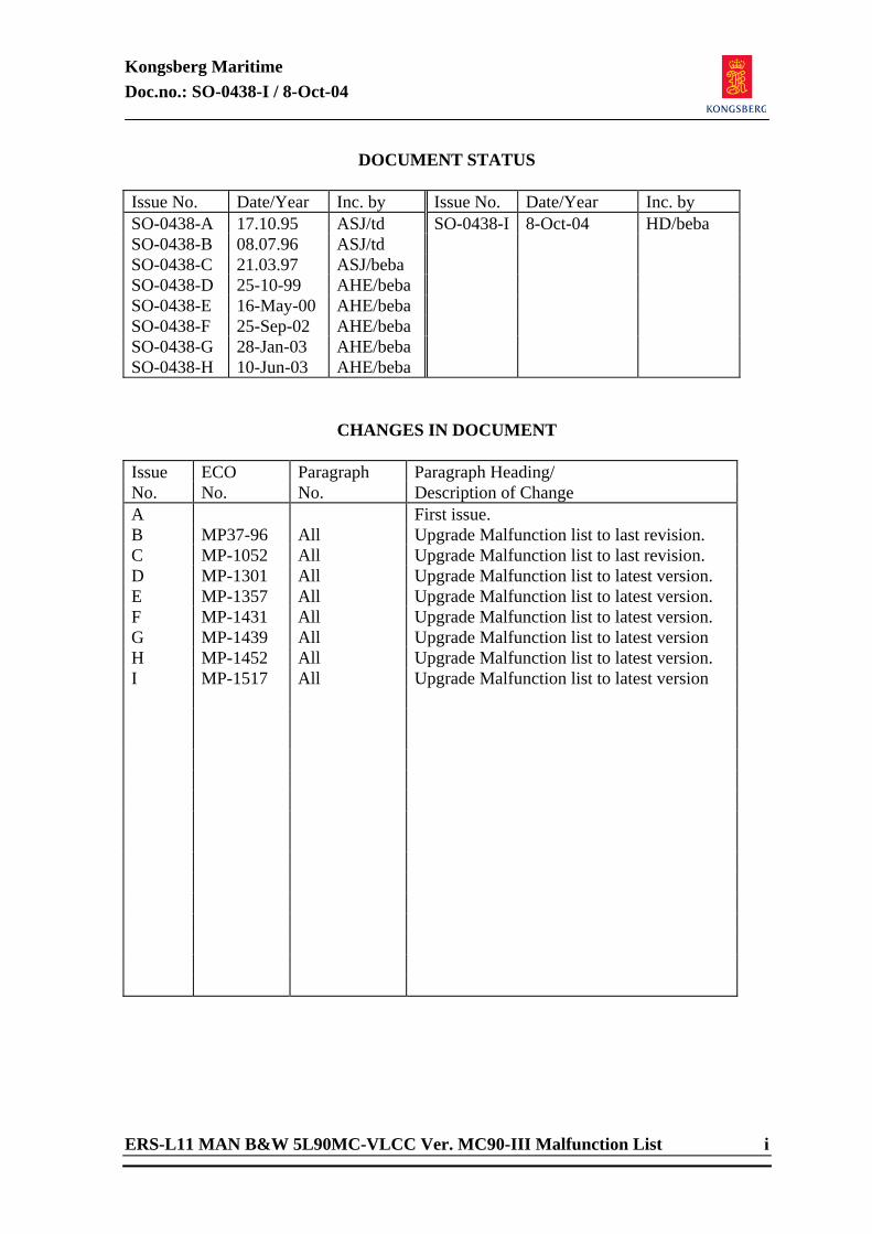
Kongsberg Maritime Doc.no.: SO-0438-I / 8-Oct-04
ERS-L11 MAN B&W 5L90MC-VLCC Ver. MC90-III Malfunction List i
DOCUMENT STATUS Issue No. Date/Year Inc. by Issue No. Date/Year Inc. by SO-0438-A 17.10.95 ASJ/td SO-0438-I 8-Oct-04 HD/beba SO-0438-B 08.07.96 ASJ/td SO-0438-C 21.03.97 ASJ/beba SO-0438-D 25-10-99 AHE/beba SO-0438-E 16-May-00 AHE/beba SO-0438-F 25-Sep-02 AHE/beba SO-0438-G 28-Jan-03 AHE/beba SO-0438-H 10-Jun-03 AHE/beba
CHANGES IN DOCUMENT Issue ECO Paragraph Paragraph Heading/ No. No. No. Description of Change A First issue. B MP37-96 All Upgrade Malfunction list to last revision. C MP-1052 All Upgrade Malfunction list to last revision. D MP-1301 All Upgrade Malfunction list to latest version. E MP-1357 All Upgrade Malfunction list to latest version. F MP-1431 All Upgrade Malfunction list to latest version. G MP-1439 All Upgrade Malfunction list to latest version H MP-1452 All Upgrade Malfunction list to latest version. I MP-1517 All Upgrade Malfunction list to latest version
Kongsberg Maritime Doc.no.: SO-0438-I / 8-Oct-04
ii ERS-L11 MAN B&W 5L90MC-VLCC Ver. MC90-III Malfunction List
TABLE OF CONTENTS 1 DIRECTORY LIST....................................................................... 1
2 VARIABLE LIST PAGES ............................................................... 2 2.1 Page:0100 MA01** SEA WATER SYSTEM....................................2 2.2 Page:0600 MA06** PURIFIER SYSTEM......................................2 2.3 Page:0700 MA07** FRESH WATER GENERATOR ..........................3 2.4 Page:0800 MA08** WASTE HEAT RECOVERY ..............................3 2.5 Page:1000 MA10** ME LTFW/HTFW SYSTEM ..............................4 2.6 Page:1100 MA11** ME FUEL OIL SYSTEM (1) .............................4 2.7 Page:1200 MA12** ME FUEL OIL SYSTEM (2) .............................5 2.8 Page:1300 MA13** ME LUB OIL SYSTEM (1)...............................5 2.9 Page:1400 MA14** ME LUB OIL SYSTEM (2)...............................6 2.10 Page:2000 MA20** ME TURBOCHARGERS (1/2) .........................6 2.11 Page:2001 MA20** ME TURBOCHARGERS (2/2) .........................7 2.12 Page:2100 MA21** ME CYLINDER 1 COMBUSTION SYSTEM ..........7 2.13 Page:2200 MA22** ME CYLINDER 2 COMBUSTION SYSTEM ..........8 2.14 Page:2300 MA23** ME CYLINDER 3 COMBUSTION SYSTEM ..........8 2.15 Page:2400 MA24** ME CYLINDER 4 COMBUSTION SYSTEM ..........9 2.16 Page:2500 MA25** ME CYLINDER 5 COMBUSTION SYSTEM ..........9 2.17 Page:3000 MA30** ME CYLINDER COOLING / LUBRICATION....... 10 2.18 Page:3100 MA31** ME BEARING LUBRICATION ........................ 10 2.19 Page:3200 MA32** STEERING GEAR SYSTEM ........................... 11 2.20 Page:3300 MA33** PROPELLER SERVO SYSTEM........................ 11 2.21 Page:3400 MA34** STERN TUBE / HULL SYSTEM ...................... 12 2.22 Page:3500 MA35** FIRE SYSTEM + MISCELLANEOUS................ 12 2.23 Page:3600 MA36** COMPRESSED AIR SYSTEM (1)................... 13 2.24 Page:3700 MA37** COMPRESSED AIR SYSTEM (2)................... 13 2.25 Page:3800 MA38** BILGE SYSTEM.......................................... 14 2.26 Page:3900 MA39** REFRIGERATION SYSTEM ........................... 14 2.27 Page:4000 MA40** DIESELGENERATOR 1 - TBCH/DO/LO ........... 15 2.28 Page:4100 MA41** DIESELGENERATOR 1 - FW/SW/MISC .......... 15 2.29 Page:4200 MA42** DIESELGENERATOR 2 - TBCH/DO/LO ........... 16 2.30 Page:4300 MA43** DIESELGENERATOR 2 - FW/SW/MISC .......... 16 2.31 Page:4400 MA44** SHAFT GENERATOR DRIVE ......................... 17 2.32 Page:4500 MA45** ELECTRIC SYSTEM (1) .............................. 17 2.33 Page:4600 MA46** ELECTRIC SYSTEM (2) .............................. 18 2.34 Page:4700 MA47** ELECTRIC SYSTEM (3) .............................. 18 2.35 Page:4800 MA48** ELECTRIC SYSTEM (4) .............................. 19 2.36 Page:5000 MA50** TURBOGENERATOR / STEAM CONDENSER .... 19 2.37 Page:5100 MA51** EXHAUST BOILER SYSTEM.......................... 20 2.38 Page:5200 MA52** STGEN / FEEDW SYSTEM........................... 20 2.39 Page:5300 MA53** OIL FIRED BOILER SYSTEM (1) ................... 21 2.40 Page:5400 MA54** OIL FIRED BOILER SYSTEM (2) ................... 21 2.41 Page:5500 MG21** CARGO PUMP TURBINES ........................ 22 2.42 Page:5600 MA56** FRESH WATER SANITARY ........................... 22
Kongsberg Maritime Doc.no.: SO-0438-I / 8-Oct-04
ERS-L11 MAN B&W 5L90MC-VLCC Ver. MC90-III Malfunction List 1
1 DIRECTORY LIST Page:0100 SEA WATER SYSTEM Page:0600 PURIFIER SYSTEM Page:0700 FRESH WATER GENERATOR Page:0800 WASTE HEAT RECOVERY Page:1000 ME LTFW/HTFW SYSTEM Page:1100 ME FUEL OIL SYSTEM (1) Page:1200 ME FUEL OIL SYSTEM (2) Page:1300 ME LUB OIL SYSTEM (1) Page:1400 ME LUB OIL SYSTEM (2) Page:2000 ME TURBOCHARGERS Page:2100 ME CYLINDER 1 COMBUSTION SYSTEM Page:2200 ME CYLINDER 2 COMBUSTION SYSTEM Page:2300 ME CYLINDER 3 COMBUSTION SYSTEM Page:2400 ME CYLINDER 4 COMBUSTION SYSTEM Page:2500 ME CYLINDER 5 COMBUSTION SYSTEM Page:3000 ME CYLINDER COOLING / LUBRICATION Page:3100 ME BEARING LUBRICATION Page:3200 STEERING GEAR SYSTEM Page:3300 PROPELLER SERVO SYSTEM Page:3400 STERN TUBE / HULL SYSTEM Page:3500 FIRE SYSTEM + MISCELLANEOUS Page:3600 COMPRESSED AIR SYSTEM (1) Page:3700 COMPRESSED AIR SYSTEM (2) Page:3800 BILGE SYSTEM Page:3900 REFRIGERATION SYSTEM Page:4000 DIESELGENERATOR 1 - TBCH/DO/LO Page:4100 DIESELGENERATOR 1 - FW/SW/MISC Page:4200 DIESELGENERATOR 2 - TBCH/DO/LO Page:4300 DIESELGENERATOR 2 - FW/SW/MISC Page:4400 SHAFT GENERATOR DRIVE Page:4500 ELECTRIC SYSTEM (1) Page:4600 ELECTRIC SYSTEM (2) Page:4700 ELECTRIC SYSTEM (3) Page:4800 ELECTRIC SYSTEM (4) Page:5000 TURBOGENERATOR / STEAM CONDENSER Page:5100 EXHAUST BOILER SYSTEM Page:5200 STGEN / FEEDW SYSTEM Page:5300 OIL FIRED BOILER SYSTEM (1) Page:5400 OIL FIRED BOILER SYSTEM (2) Page:5500 CARGO PUMP TURBINES Page:5600 FRESH WATER SANITARY
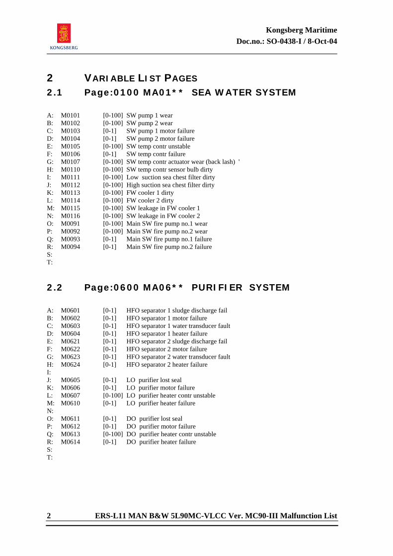
Kongsberg Maritime Doc.no.: SO-0438-I / 8-Oct-04
2 ERS-L11 MAN B&W 5L90MC-VLCC Ver. MC90-III Malfunction List
2 VARIABLE LIST PAGES 2.1 Page:0100 MA01** SEA WATER SYSTEM
A: M0101 [0-100] SW pump 1 wear B: M0102 [0-100] SW pump 2 wear C: M0103 [0-1] SW pump 1 motor failure D: M0104 [0-1] SW pump 2 motor failure E: M0105 [0-100] SW temp contr unstable F: M0106 [0-1] SW temp contr failure G: M0107 [0-100] SW temp contr actuator wear (back lash) ' H: M0110 [0-100] SW temp contr sensor bulb dirty I: M0111 [0-100] Low suction sea chest filter dirty J: M0112 [0-100] High suction sea chest filter dirty K: M0113 [0-100] FW cooler 1 dirty L: M0114 [0-100] FW cooler 2 dirty M: M0115 [0-100] SW leakage in FW cooler 1 N: M0116 [0-100] SW leakage in FW cooler 2 O: M0091 [0-100] Main SW fire pump no.1 wear P: M0092 [0-100] Main SW fire pump no.2 wear Q: M0093 [0-1] Main SW fire pump no.1 failure R: M0094 [0-1] Main SW fire pump no.2 failure S: T: 2.2 Page:0600 MA06** PURIFIER SYSTEM
A: M0601 [0-1] HFO separator 1 sludge discharge fail B: M0602 [0-1] HFO separator 1 motor failure C: M0603 [0-1] HFO separator 1 water transducer fault D: M0604 [0-1] HFO separator 1 heater failure E: M0621 [0-1] HFO separator 2 sludge discharge fail F: M0622 [0-1] HFO separator 2 motor failure G: M0623 [0-1] HFO separator 2 water transducer fault H: M0624 [0-1] HFO separator 2 heater failure I: J: M0605 [0-1] LO purifier lost seal K: M0606 [0-1] LO purifier motor failure L: M0607 [0-100] LO purifier heater contr unstable M: M0610 [0-1] LO purifier heater failure N: O: M0611 [0-1] DO purifier lost seal P: M0612 [0-1] DO purifier motor failure Q: M0613 [0-100] DO purifier heater contr unstable R: M0614 [0-1] DO purifier heater failure S: T:
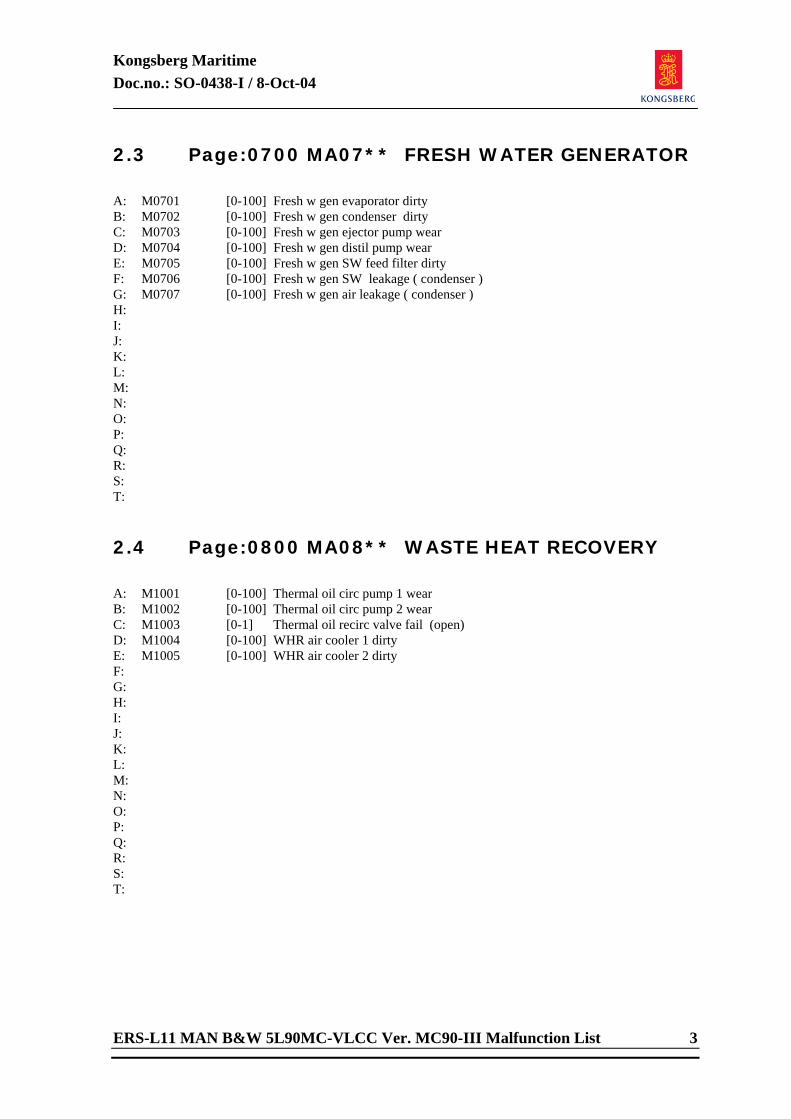
Kongsberg Maritime Doc.no.: SO-0438-I / 8-Oct-04
ERS-L11 MAN B&W 5L90MC-VLCC Ver. MC90-III Malfunction List 3
2.3 Page:0700 MA07** FRESH WATER GENERATOR
A: M0701 [0-100] Fresh w gen evaporator dirty B: M0702 [0-100] Fresh w gen condenser dirty C: M0703 [0-100] Fresh w gen ejector pump wear D: M0704 [0-100] Fresh w gen distil pump wear E: M0705 [0-100] Fresh w gen SW feed filter dirty F: M0706 [0-100] Fresh w gen SW leakage ( condenser ) G: M0707 [0-100] Fresh w gen air leakage ( condenser ) H: I: J: K: L: M: N: O: P: Q: R: S: T: 2.4 Page:0800 MA08** WASTE HEAT RECOVERY
A: M1001 [0-100] Thermal oil circ pump 1 wear B: M1002 [0-100] Thermal oil circ pump 2 wear C: M1003 [0-1] Thermal oil recirc valve fail (open) D: M1004 [0-100] WHR air cooler 1 dirty E: M1005 [0-100] WHR air cooler 2 dirty F: G: H: I: J: K: L: M: N: O: P: Q: R: S: T:
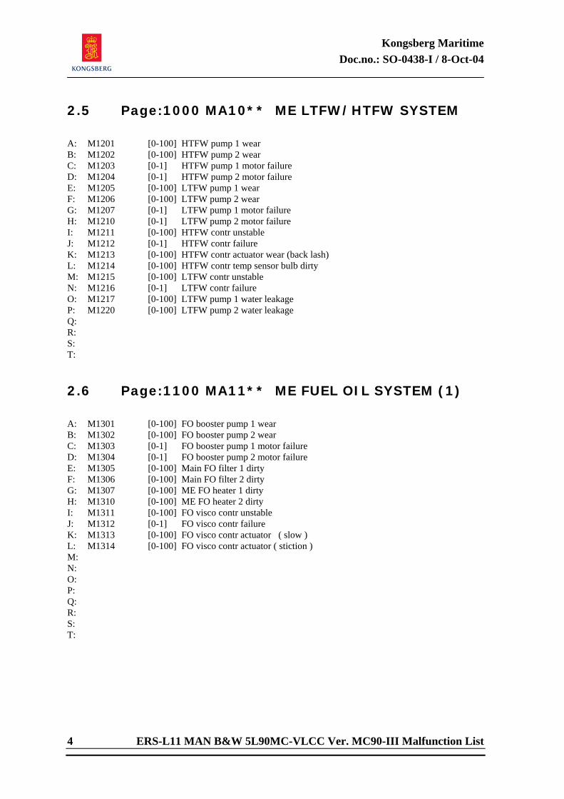
Kongsberg Maritime Doc.no.: SO-0438-I / 8-Oct-04
4 ERS-L11 MAN B&W 5L90MC-VLCC Ver. MC90-III Malfunction List
2.5 Page:1000 MA10** ME LTFW/HTFW SYSTEM
A: M1201 [0-100] HTFW pump 1 wear B: M1202 [0-100] HTFW pump 2 wear C: M1203 [0-1] HTFW pump 1 motor failure D: M1204 [0-1] HTFW pump 2 motor failure E: M1205 [0-100] LTFW pump 1 wear F: M1206 [0-100] LTFW pump 2 wear G: M1207 [0-1] LTFW pump 1 motor failure H: M1210 [0-1] LTFW pump 2 motor failure I: M1211 [0-100] HTFW contr unstable J: M1212 [0-1] HTFW contr failure K: M1213 [0-100] HTFW contr actuator wear (back lash) L: M1214 [0-100] HTFW contr temp sensor bulb dirty M: M1215 [0-100] LTFW contr unstable N: M1216 [0-1] LTFW contr failure O: M1217 [0-100] LTFW pump 1 water leakage P: M1220 [0-100] LTFW pump 2 water leakage Q: R: S: T: 2.6 Page:1100 MA11** ME FUEL OIL SYSTEM (1)
A: M1301 [0-100] FO booster pump 1 wear B: M1302 [0-100] FO booster pump 2 wear C: M1303 [0-1] FO booster pump 1 motor failure D: M1304 [0-1] FO booster pump 2 motor failure E: M1305 [0-100] Main FO filter 1 dirty F: M1306 [0-100] Main FO filter 2 dirty G: M1307 [0-100] ME FO heater 1 dirty H: M1310 [0-100] ME FO heater 2 dirty I: M1311 [0-100] FO visco contr unstable J: M1312 [0-1] FO visco contr failure K: M1313 [0-100] FO visco contr actuator ( slow ) L: M1314 [0-100] FO visco contr actuator ( stiction ) M: N: O: P: Q: R: S: T:
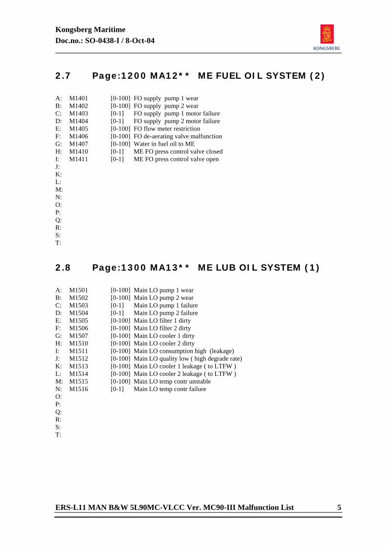
Kongsberg Maritime Doc.no.: SO-0438-I / 8-Oct-04
ERS-L11 MAN B&W 5L90MC-VLCC Ver. MC90-III Malfunction List 5
2.7 Page:1200 MA12** ME FUEL OIL SYSTEM (2)
A: M1401 [0-100] FO supply pump 1 wear B: M1402 [0-100] FO supply pump 2 wear C: M1403 [0-1] FO supply pump 1 motor failure D: M1404 [0-1] FO supply pump 2 motor failure E: M1405 [0-100] FO flow meter restriction F: M1406 [0-100] FO de-aerating valve malfunction G: M1407 [0-100] Water in fuel oil to ME H: M1410 [0-1] ME FO press control valve closed I: M1411 [0-1] ME FO press control valve open J: K: L: M: N: O: P: Q: R: S: T: 2.8 Page:1300 MA13** ME LUB OIL SYSTEM (1)
A: M1501 [0-100] Main LO pump 1 wear B: M1502 [0-100] Main LO pump 2 wear C: M1503 [0-1] Main LO pump 1 failure D: M1504 [0-1] Main LO pump 2 failure E: M1505 [0-100] Main LO filter 1 dirty F: M1506 [0-100] Main LO filter 2 dirty G: M1507 [0-100] Main LO cooler 1 dirty H: M1510 [0-100] Main LO cooler 2 dirty I: M1511 [0-100] Main LO consumption high (leakage) J: M1512 [0-100] Main LO quality low ( high degrade rate) K: M1513 [0-100] Main LO cooler 1 leakage ( to LTFW ) L: M1514 [0-100] Main LO cooler 2 leakage ( to LTFW ) M: M1515 [0-100] Main LO temp contr unstable N: M1516 [0-1] Main LO temp contr failure O: P: Q: R: S: T:
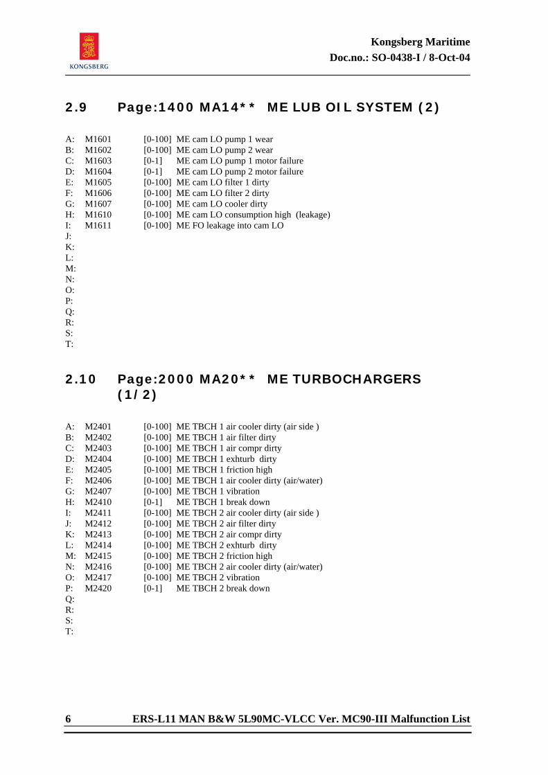
Kongsberg Maritime Doc.no.: SO-0438-I / 8-Oct-04
6 ERS-L11 MAN B&W 5L90MC-VLCC Ver. MC90-III Malfunction List
2.9 Page:1400 MA14** ME LUB OIL SYSTEM (2)
A: M1601 [0-100] ME cam LO pump 1 wear B: M1602 [0-100] ME cam LO pump 2 wear C: M1603 [0-1] ME cam LO pump 1 motor failure D: M1604 [0-1] ME cam LO pump 2 motor failure E: M1605 [0-100] ME cam LO filter 1 dirty F: M1606 [0-100] ME cam LO filter 2 dirty G: M1607 [0-100] ME cam LO cooler dirty H: M1610 [0-100] ME cam LO consumption high (leakage) I: M1611 [0-100] ME FO leakage into cam LO J: K: L: M: N: O: P: Q: R: S: T: 2.10 Page:2000 MA20** ME TURBOCHARGERS
(1/2)
A: M2401 [0-100] ME TBCH 1 air cooler dirty (air side ) B: M2402 [0-100] ME TBCH 1 air filter dirty C: M2403 [0-100] ME TBCH 1 air compr dirty D: M2404 [0-100] ME TBCH 1 exhturb dirty E: M2405 [0-100] ME TBCH 1 friction high F: M2406 [0-100] ME TBCH 1 air cooler dirty (air/water) G: M2407 [0-100] ME TBCH 1 vibration H: M2410 [0-1] ME TBCH 1 break down I: M2411 [0-100] ME TBCH 2 air cooler dirty (air side ) J: M2412 [0-100] ME TBCH 2 air filter dirty K: M2413 [0-100] ME TBCH 2 air compr dirty L: M2414 [0-100] ME TBCH 2 exhturb dirty M: M2415 [0-100] ME TBCH 2 friction high N: M2416 [0-100] ME TBCH 2 air cooler dirty (air/water) O: M2417 [0-100] ME TBCH 2 vibration P: M2420 [0-1] ME TBCH 2 break down Q: R: S: T:
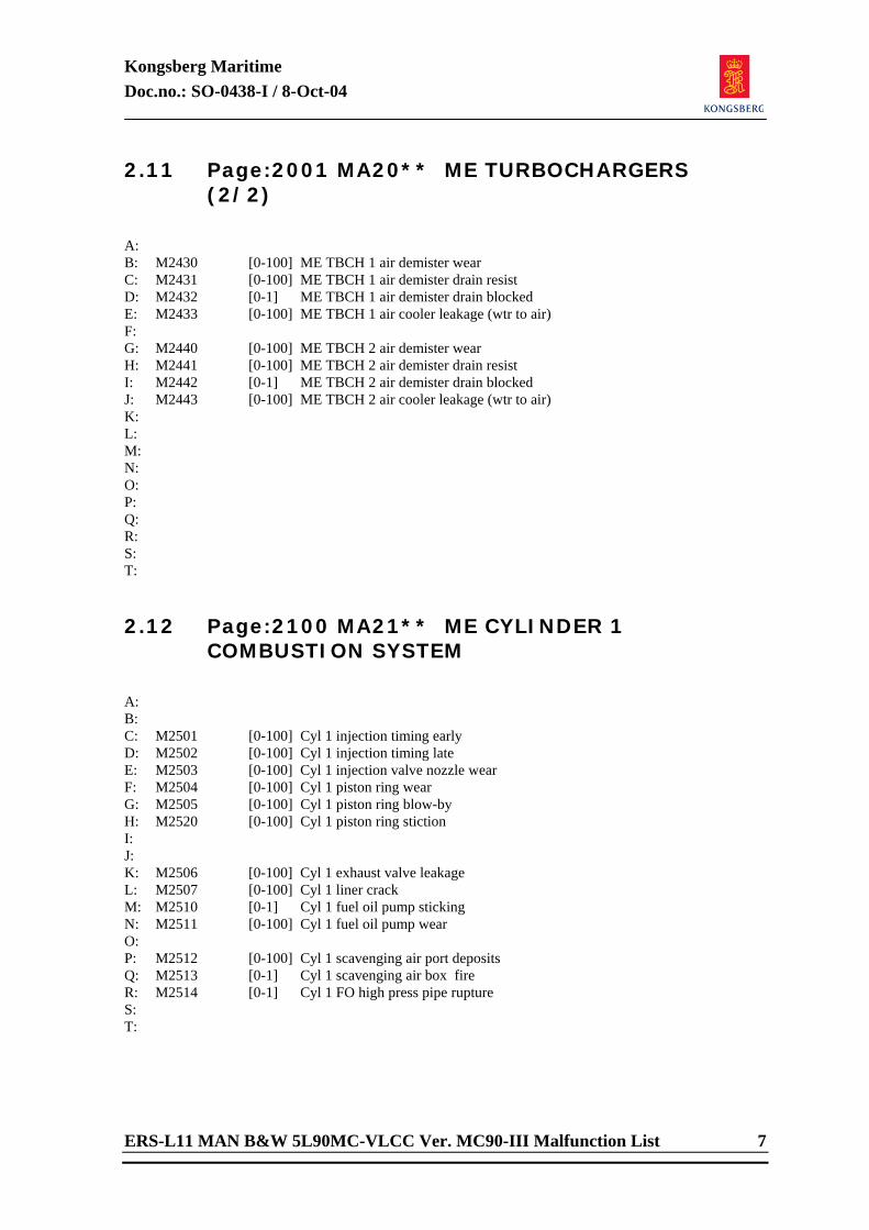
Kongsberg Maritime Doc.no.: SO-0438-I / 8-Oct-04
ERS-L11 MAN B&W 5L90MC-VLCC Ver. MC90-III Malfunction List 7
2.11 Page:2001 MA20** ME TURBOCHARGERS (2/2)
A: B: M2430 [0-100] ME TBCH 1 air demister wear C: M2431 [0-100] ME TBCH 1 air demister drain resist D: M2432 [0-1] ME TBCH 1 air demister drain blocked E: M2433 [0-100] ME TBCH 1 air cooler leakage (wtr to air) F: G: M2440 [0-100] ME TBCH 2 air demister wear H: M2441 [0-100] ME TBCH 2 air demister drain resist I: M2442 [0-1] ME TBCH 2 air demister drain blocked J: M2443 [0-100] ME TBCH 2 air cooler leakage (wtr to air) K: L: M: N: O: P: Q: R: S: T: 2.12 Page:2100 MA21** ME CYLINDER 1
COMBUSTION SYSTEM
A: B: C: M2501 [0-100] Cyl 1 injection timing early D: M2502 [0-100] Cyl 1 injection timing late E: M2503 [0-100] Cyl 1 injection valve nozzle wear F: M2504 [0-100] Cyl 1 piston ring wear G: M2505 [0-100] Cyl 1 piston ring blow-by H: M2520 [0-100] Cyl 1 piston ring stiction I: J: K: M2506 [0-100] Cyl 1 exhaust valve leakage L: M2507 [0-100] Cyl 1 liner crack M: M2510 [0-1] Cyl 1 fuel oil pump sticking N: M2511 [0-100] Cyl 1 fuel oil pump wear O: P: M2512 [0-100] Cyl 1 scavenging air port deposits Q: M2513 [0-1] Cyl 1 scavenging air box fire R: M2514 [0-1] Cyl 1 FO high press pipe rupture S: T:
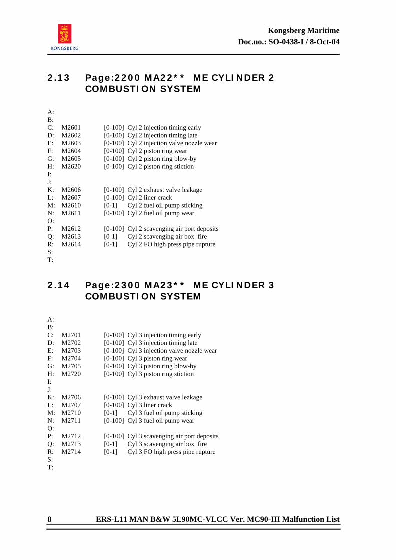
Kongsberg Maritime Doc.no.: SO-0438-I / 8-Oct-04
8 ERS-L11 MAN B&W 5L90MC-VLCC Ver. MC90-III Malfunction List
2.13 Page:2200 MA22** ME CYLINDER 2 COMBUSTION SYSTEM
A: B: C: M2601 [0-100] Cyl 2 injection timing early D: M2602 [0-100] Cyl 2 injection timing late E: M2603 [0-100] Cyl 2 injection valve nozzle wear F: M2604 [0-100] Cyl 2 piston ring wear G: M2605 [0-100] Cyl 2 piston ring blow-by H: M2620 [0-100] Cyl 2 piston ring stiction I: J: K: M2606 [0-100] Cyl 2 exhaust valve leakage L: M2607 [0-100] Cyl 2 liner crack M: M2610 [0-1] Cyl 2 fuel oil pump sticking N: M2611 [0-100] Cyl 2 fuel oil pump wear O: P: M2612 [0-100] Cyl 2 scavenging air port deposits Q: M2613 [0-1] Cyl 2 scavenging air box fire R: M2614 [0-1] Cyl 2 FO high press pipe rupture S: T: 2.14 Page:2300 MA23** ME CYLINDER 3
COMBUSTION SYSTEM
A: B: C: M2701 [0-100] Cyl 3 injection timing early D: M2702 [0-100] Cyl 3 injection timing late E: M2703 [0-100] Cyl 3 injection valve nozzle wear F: M2704 [0-100] Cyl 3 piston ring wear G: M2705 [0-100] Cyl 3 piston ring blow-by H: M2720 [0-100] Cyl 3 piston ring stiction I: J: K: M2706 [0-100] Cyl 3 exhaust valve leakage L: M2707 [0-100] Cyl 3 liner crack M: M2710 [0-1] Cyl 3 fuel oil pump sticking N: M2711 [0-100] Cyl 3 fuel oil pump wear O: P: M2712 [0-100] Cyl 3 scavenging air port deposits Q: M2713 [0-1] Cyl 3 scavenging air box fire R: M2714 [0-1] Cyl 3 FO high press pipe rupture S: T:
Kongsberg Maritime Doc.no.: SO-0438-I / 8-Oct-04
ERS-L11 MAN B&W 5L90MC-VLCC Ver. MC90-III Malfunction List 9
2.15 Page:2400 MA24** ME CYLINDER 4 COMBUSTION SYSTEM
A: B: C: M3001 [0-100] Cyl 4 injection timing early D: M3002 [0-100] Cyl 4 injection timing late E: M3003 [0-100] Cyl 4 injection valve nozzle wear F: M3004 [0-100] Cyl 4 piston ring wear G: M3005 [0-100] Cyl 4 piston ring blow-by H: M3020 [0-100] Cyl 4 piston ring stiction I: J: K: M3006 [0-100] Cyl 4 exhaust valve leakage L: M3007 [0-100] Cyl 4 liner crack M: M3010 [0-1] Cyl 4 fuel oil pump sticking N: M3011 [0-100] Cyl 4 fuel oil pump wear O: P: M3012 [0-100] Cyl 4 scavenging air port deposits Q: M3013 [0-1] Cyl 4 scavenging air box fire R: M3014 [0-1] Cyl 4 FO high press pipe rupture S: T: 2.16 Page:2500 MA25** ME CYLINDER 5
COMBUSTION SYSTEM
A: B: C: M3101 [0-100] Cyl 5 injection timing early D: M3102 [0-100] Cyl 5 injection timing late E: M3103 [0-100] Cyl 5 injection valve nozzle wear F: M3104 [0-100] Cyl 5 piston ring wear G: M3105 [0-100] Cyl 5 piston ring blow-by H: M3120 [0-100] Cyl 5 piston ring stiction I: J: K: M3106 [0-100] Cyl 5 exhaust valve leakage L: M3107 [0-100] Cyl 5 liner crack M: M3110 [0-1] Cyl 5 fuel oil pump sticking N: M3111 [0-100] Cyl 5 fuel oil pump wear O: P: M3112 [0-100] Cyl 5 scavenging air port deposits Q: M3113 [0-1] Cyl 5 scavenging air box fire R: M3114 [0-1] Cyl 5 FO high press pipe rupture S: T:
Kongsberg Maritime Doc.no.: SO-0438-I / 8-Oct-04
10 ERS-L11 MAN B&W 5L90MC-VLCC Ver. MC90-III Malfunction List
2.17 Page:3000 MA30** ME CYLINDER COOLING / LUBRICATION
A: M3601 [0-100] Cyl 1 piston cooling flow low B: M3602 [0-100] Cyl 2 piston cooling flow low C: M3603 [0-100] Cyl 3 piston cooling flow low D: M3604 [0-100] Cyl 4 piston cooling flow low E: M3605 [0-100] Cyl 5 piston cooling flow low F: M3606 [0-100] Cyl 1 liner cooling flow low G: M3607 [0-100] Cyl 2 liner cooling flow low H: M3610 [0-100] Cyl 3 liner cooling flow low I: M3611 [0-100] Cyl 4 liner cooling flow low J: M3612 [0-100] Cyl 5 liner cooling flow low K: M3613 [0-100] Cyl 1 liner lubric flow low L: M3614 [0-100] Cyl 2 liner lubric flow low M: M3615 [0-100] Cyl 3 liner lubric flow low N: M3616 [0-100] Cyl 4 liner lubric flow low O: M3617 [0-100] Cyl 5 liner lubric flow low P: Q: R: S: T: 2.18 Page:3100 MA31** ME BEARING LUBRICATION
A: M3701 [0-100] Cyl 1 crosshead lubrication low B: M3702 [0-100] Cyl 2 crosshead lubrication low C: M3703 [0-100] Cyl 3 crosshead lubrication low D: M3704 [0-100] Cyl 4 crosshead lubrication low E: M3705 [0-100] Cyl 5 crosshead lubrication low F: M3706 [0-100] Cyl 1 crank shaft lubrication low G: M3707 [0-100] Cyl 2 crank shaft lubrication low H: M3710 [0-100] Cyl 3 crank shaft lubrication low I: M3711 [0-100] Cyl 4 crank shaft lubrication low J: M3712 [0-100] Cyl 5 crank shaft lubrication low K: M3713 [0-100] Main bearing 1 lubrication low L: M3714 [0-100] Main bearing 2 lubrication low M: M3715 [0-100] Main bearing 3 lubrication low N: M3716 [0-100] Main bearing 4 lubrication low O: M3717 [0-100] Main bearing 5 lubrication low P: M3720 [0-100] Main bearing 6 lubrication low Q: M3721 [0-100] Thrust bearing lubrication low R: S: T:
Kongsberg Maritime Doc.no.: SO-0438-I / 8-Oct-04
ERS-L11 MAN B&W 5L90MC-VLCC Ver. MC90-III Malfunction List 11
2.19 Page:3200 MA32** STEERING GEAR SYSTEM
A: M4120 [0-1] Rudder command ( remote control) failure B: C: M1580 [0-1] Steering gear pump 1 motor failure D: M1581 [0-1] Steering gear pump 2 motor failure E: F: M1582 [0-100] Steering gear pump 1 wear G: M1583 [0-100] Steering gear pump 2 wear H: I: M1584 [0-100] Steering gear sump 1 leakage J: M1585 [0-100] Steering gear sump 2 leakage K: M1586 [0-100] Steering gear pump 1 leakage L: M1587 [0-100] Steering gear pump 2 leakage M: N: M1588 [0-100] Steering gear filter 1 dirty O: M1589 [0-100] Steering gear filter 2 dirty P: Q: M1590 [0-1] Steering gear safematic valve failure R: S: M1591 [0-1] Steering gear bypass valve 1 failure T: M1592 [0-1] Steering gear bypass valve 2 failure 2.20 Page:3300 MA33** PROPELLER SERVO SYSTEM
A: M4101 [0-100] Propeller servo LO pump 1 wear B: M4102 [0-100] Propeller servo LO pump 2 wear C: M4103 [0-1] Propeller servo LO pump 1 failure D: M4104 [0-1] Propeller servo LO pump 2 failure E: M4105 [0-100] Propeller servo LO filter 1 dirty F: M4106 [0-100] Propeller servo LO filter 2 dirty G: M4107 [0-100] Propeller servo LO cooler dirty H: M4110 [0-1] Propeller servo controller fail I: M4111 [0-100] Prop servo LO temp contr gain high J: M4112 [0-100] Prop servo LO press contr gain high K: M4113 [0-100] Propeller wear (low efficiency) L: M4114 [0-1] Propeller lost (shaft breakage) M: M4115 [0-100] Propeller seal (leaking hub seal) N: O: P: Q: R: S: T:
Kongsberg Maritime Doc.no.: SO-0438-I / 8-Oct-04
12 ERS-L11 MAN B&W 5L90MC-VLCC Ver. MC90-III Malfunction List
2.21 Page:3400 MA34** STERN TUBE / HULL SYSTEM
A: M4201 [0-1] Stern tube LO pump 1 failure B: M4202 [0-1] Stern tube LO pump 2 failure C: M4203 [0-100] Stern tube LO cooler dirty D: M4204 [0-100] Stern tube fore bearing lubri low E: M4205 [0-100] Stern tube aft bearing lubri low F: M4206 [0-100] Stern tube aft seal ring wear G: M4210 [0-100] Ship hull fouling H: I: J: K: L: M: N: O: P: Q: R: S: T: 2.22 Page:3500 MA35** FIRE SYSTEM +
MISCELLANEOUS
A: M4301 [0-1] Fire in engine room area B: M4302 [0-1] Fire in deck area C: D: E: F: G: H: I: J: K: L: M: N: O: P: Q: R: S: T:
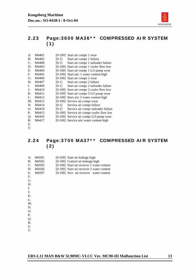
Kongsberg Maritime Doc.no.: SO-0438-I / 8-Oct-04
ERS-L11 MAN B&W 5L90MC-VLCC Ver. MC90-III Malfunction List 13
2.23 Page:3600 MA36** COMPRESSED AIR SYSTEM (1)
A: M4401 [0-100] Start air compr 1 wear B: M4402 [0-1] Start air compr 1 failure C: M4408 [0-1] Start air compr 1 unloader failure D: M4403 [0-100] Start air compr 1 coolw flow low E: M4404 [0-100] Start air compr 1 LO pump wear F: M4405 [0-100] Start airc 1 water content high G: M4406 [0-100] Start air compr 2 wear H: M4407 [0-1] Start air compr 2 failure I: M4409 [0-1] Start air compr 2 unloader failure J: M4410 [0-100] Start air compr 2 coolw flow low K: M4411 [0-100] Start air compr 2 LO pump wear L: M4412 [0-100] Start airc 2 water content high M: M4413 [0-100] Service air compr wear N: M4414 [0-1] Service air compr failure O: M4418 [0-1] Service air compr unloader failure P: M4415 [0-100] Service air compr coolw flow low Q: M4416 [0-100] Service air compr LO pump wear R: M4417 [0-100] Service airc water content high S: T: 2.24 Page:3700 MA37** COMPRESSED AIR SYSTEM
(2)
A: M4501 [0-100] Start air leakage high B: M4502 [0-100] Control air leakage high C: M4505 [0-100] Start air receiver 1 water content D: M4506 [0-100] Start air receiver 2 water content E: M4507 [0-100] Serv air receiver water content F: G: H: I: J: K: L: M: N: O: P: Q: R: S: T:
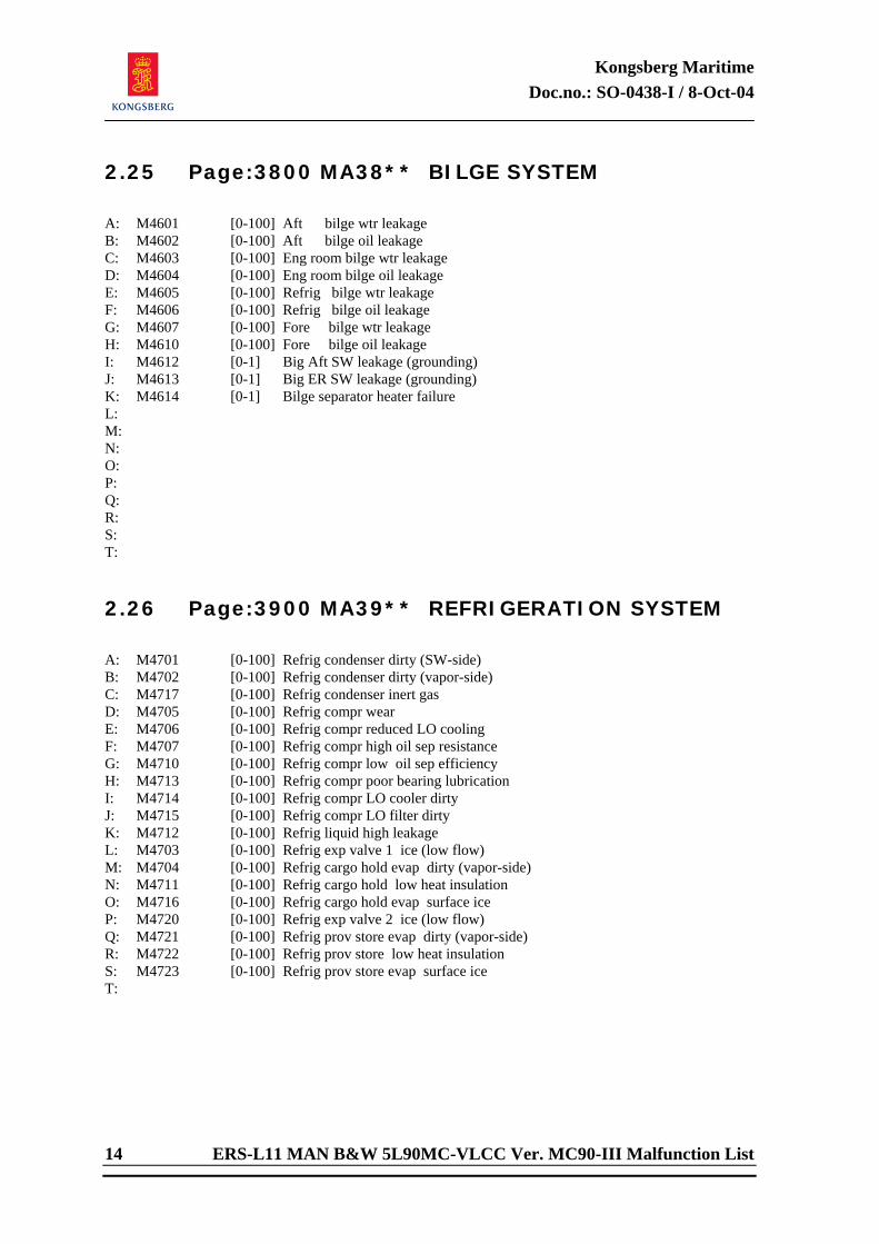
Kongsberg Maritime Doc.no.: SO-0438-I / 8-Oct-04
14 ERS-L11 MAN B&W 5L90MC-VLCC Ver. MC90-III Malfunction List
2.25 Page:3800 MA38** BILGE SYSTEM
A: M4601 [0-100] Aft bilge wtr leakage B: M4602 [0-100] Aft bilge oil leakage C: M4603 [0-100] Eng room bilge wtr leakage D: M4604 [0-100] Eng room bilge oil leakage E: M4605 [0-100] Refrig bilge wtr leakage F: M4606 [0-100] Refrig bilge oil leakage G: M4607 [0-100] Fore bilge wtr leakage H: M4610 [0-100] Fore bilge oil leakage I: M4612 [0-1] Big Aft SW leakage (grounding) J: M4613 [0-1] Big ER SW leakage (grounding) K: M4614 [0-1] Bilge separator heater failure L: M: N: O: P: Q: R: S: T: 2.26 Page:3900 MA39** REFRIGERATION SYSTEM
A: M4701 [0-100] Refrig condenser dirty (SW-side) B: M4702 [0-100] Refrig condenser dirty (vapor-side) C: M4717 [0-100] Refrig condenser inert gas D: M4705 [0-100] Refrig compr wear E: M4706 [0-100] Refrig compr reduced LO cooling F: M4707 [0-100] Refrig compr high oil sep resistance G: M4710 [0-100] Refrig compr low oil sep efficiency H: M4713 [0-100] Refrig compr poor bearing lubrication I: M4714 [0-100] Refrig compr LO cooler dirty J: M4715 [0-100] Refrig compr LO filter dirty K: M4712 [0-100] Refrig liquid high leakage L: M4703 [0-100] Refrig exp valve 1 ice (low flow) M: M4704 [0-100] Refrig cargo hold evap dirty (vapor-side) N: M4711 [0-100] Refrig cargo hold low heat insulation O: M4716 [0-100] Refrig cargo hold evap surface ice P: M4720 [0-100] Refrig exp valve 2 ice (low flow) Q: M4721 [0-100] Refrig prov store evap dirty (vapor-side) R: M4722 [0-100] Refrig prov store low heat insulation S: M4723 [0-100] Refrig prov store evap surface ice T:
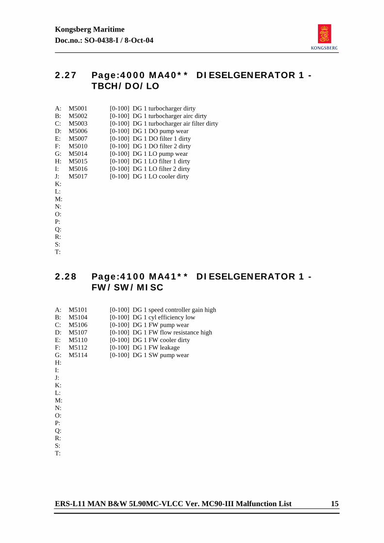
Kongsberg Maritime Doc.no.: SO-0438-I / 8-Oct-04
ERS-L11 MAN B&W 5L90MC-VLCC Ver. MC90-III Malfunction List 15
2.27 Page:4000 MA40** DIESELGENERATOR 1 - TBCH/DO/LO
A: M5001 [0-100] DG 1 turbocharger dirty B: M5002 [0-100] DG 1 turbocharger airc dirty C: M5003 [0-100] DG 1 turbocharger air filter dirty D: M5006 [0-100] DG 1 DO pump wear E: M5007 [0-100] DG 1 DO filter 1 dirty F: M5010 [0-100] DG 1 DO filter 2 dirty G: M5014 [0-100] DG 1 LO pump wear H: M5015 [0-100] DG 1 LO filter 1 dirty I: M5016 [0-100] DG 1 LO filter 2 dirty J: M5017 [0-100] DG 1 LO cooler dirty K: L: M: N: O: P: Q: R: S: T: 2.28 Page:4100 MA41** DIESELGENERATOR 1 -
FW/SW/MISC
A: M5101 [0-100] DG 1 speed controller gain high B: M5104 [0-100] DG 1 cyl efficiency low C: M5106 [0-100] DG 1 FW pump wear D: M5107 [0-100] DG 1 FW flow resistance high E: M5110 [0-100] DG 1 FW cooler dirty F: M5112 [0-100] DG 1 FW leakage G: M5114 [0-100] DG 1 SW pump wear H: I: J: K: L: M: N: O: P: Q: R: S: T:
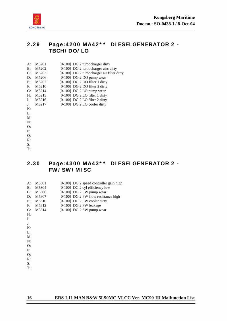
Kongsberg Maritime Doc.no.: SO-0438-I / 8-Oct-04
16 ERS-L11 MAN B&W 5L90MC-VLCC Ver. MC90-III Malfunction List
2.29 Page:4200 MA42** DIESELGENERATOR 2 - TBCH/DO/LO
A: M5201 [0-100] DG 2 turbocharger dirty B: M5202 [0-100] DG 2 turbocharger airc dirty C: M5203 [0-100] DG 2 turbocharger air filter dirty D: M5206 [0-100] DG 2 DO pump wear E: M5207 [0-100] DG 2 DO filter 1 dirty F: M5210 [0-100] DG 2 DO filter 2 dirty G: M5214 [0-100] DG 2 LO pump wear H: M5215 [0-100] DG 2 LO filter 1 dirty I: M5216 [0-100] DG 2 LO filter 2 dirty J: M5217 [0-100] DG 2 LO cooler dirty K: L: M: N: O: P: Q: R: S: T: 2.30 Page:4300 MA43** DIESELGENERATOR 2 -
FW/SW/MISC
A: M5301 [0-100] DG 2 speed controller gain high B: M5304 [0-100] DG 2 cyl efficiency low C: M5306 [0-100] DG 2 FW pump wear D: M5307 [0-100] DG 2 FW flow resistance high E: M5310 [0-100] DG 2 FW cooler dirty F: M5312 [0-100] DG 2 FW leakage G: M5314 [0-100] DG 2 SW pump wear H: I: J: K: L: M: N: O: P: Q: R: S: T:
Kongsberg Maritime Doc.no.: SO-0438-I / 8-Oct-04
ERS-L11 MAN B&W 5L90MC-VLCC Ver. MC90-III Malfunction List 17
2.31 Page:4400 MA44** SHAFT GENERATOR DRIVE
A: B: C: D: E: F: M5406 [0-1] SG clutch failure G: H: I: J: K: L: M: N: O: P: Q: R: S: T: 2.32 Page:4500 MA45** ELECTRIC SYSTEM (1)
A: M5501 [0-100] DG 1 volt controller gain high B: M5502 [0-100] DG 2 volt controller gain high C: M5503 [0-100] TG volt controller gain high D: M5504 [0-100] SG volt controller gain high E: F: M5511 [0-100] DG 1 magnetization unbalance G: M5512 [0-100] DG 2 magnetization unbalance H: M5513 [0-100] TG magnetization unbalance I: M5514 [0-100] SG magnetization unbalance J: K: M5520 [0-1] Electric earth leakage L: M5521 [0-1] Short circuit - Busbar 1 M: M5522 [0-1] Short circuit - Busbar 2 N: O: P: M5523 [0-1] Electric earth leakage (r - Accom light) Q: M5524 [0-1] Electric earth leakage (s - Deck light) R: M5525 [0-1] Electric earth leakage (t - ER light) S: T:
Kongsberg Maritime Doc.no.: SO-0438-I / 8-Oct-04
18 ERS-L11 MAN B&W 5L90MC-VLCC Ver. MC90-III Malfunction List
2.33 Page:4600 MA46** ELECTRIC SYSTEM (2)
A: M5601 [0-100] DG 1 misadjusted return power relay B: M5602 [0-100] DG 2 misadjusted return power relay C: M5603 [0-100] TG misadjusted return power relay D: M5604 [0-100] SG misadjusted return power relay E: F: M5606 [0-100] DG 1 misadjusted overload relay G: M5607 [0-100] DG 2 misadjusted overload relay H: M5610 [0-100] TG misadjusted overload relay I: M5611 [0-100] SG misadjusted overload relay J: K: M5613 [0-1] DG 1 exitation failure L: M5614 [0-1] DG 2 exitation failure M: M5615 [0-1] TG exitation failure N: M5616 [0-1] SG exitation failure O: P: Q: R: S: T: 2.34 Page:4700 MA47** ELECTRIC SYSTEM (3)
A: M5701 [0-1] Deck crane motor earth leakage B: M5702 [0-1] Bow thruster motor earth leakage C: M5703 [0-1] Main SW pump 1 motor earth leakage D: M5704 [0-1] Main SW pump 2 motor earth leakage E: M5705 [0-1] Main LO pump 1 motor earth leakage F: M5706 [0-1] Main LO pump 2 motor earth leakage G: M5707 [0-1] LTFW pump 1 motor earth leakage H: M5710 [0-1] LTFW pump 2 motor earth leakage I: M5711 [0-1] HTFW pump 1 motor earth leakage J: M5712 [0-1] HTFW pump 2 motor earth leakage K: M5713 [0-1] FO booster pump 1 motor earth leakage L: M5714 [0-1] FO booster pump 2 motor earth leakage M: M5715 [0-1] FO supply pump 1 motor earth leakage N: M5716 [0-1] FO supply pump 2 motor earth leakage O: M5717 [0-1] Aux feedw pump motor earth leakage P: M5720 [0-1] Comb air fan motor earth leakage Q: R: S: T:
Kongsberg Maritime Doc.no.: SO-0438-I / 8-Oct-04
ERS-L11 MAN B&W 5L90MC-VLCC Ver. MC90-III Malfunction List 19
2.35 Page:4800 MA48** ELECTRIC SYSTEM (4)
A: M6001 [0-1] Deck crane cable earth leakage B: M6002 [0-1] Bow thruster cable earth leakage C: M6003 [0-1] Main SW pump 1 cable earth leakage D: M6004 [0-1] Main SW pump 2 cable earth leakage E: M6005 [0-1] Main LO pump 1 cable earth leakage F: M6006 [0-1] Main LO pump 2 cable earth leakage G: M6007 [0-1] LTFW pump 1 cable earth leakage H: M6010 [0-1] LTFW pump 2 cable earth leakage I: M6011 [0-1] HTFW pump 1 cable earth leakage J: M6012 [0-1] HTFW pump 2 cable earth leakage K: M6013 [0-1] FO booster pump 1 cable earth leakage L: M6014 [0-1] FO booster pump 2 cable earth leakage M: M6015 [0-1] FO supply pump 1 cable earth leakage N: M6016 [0-1] FO supply pump 2 cable earth leakage O: M6017 [0-1] Aux feedw pump cable earth leakage P: M6020 [0-1] Comb air fan cable earth leakage Q: R: S: T: 2.36 Page:5000 MA50** TURBOGENERATOR /
STEAM CONDENSER
A: M6201 [0-100] TG speed contr gain high B: M6202 [0-100] Turbine efficiency low C: M6203 [0-100] TG mech LO pump wear D: M6204 [0-100] TG LO cooler dirty E: M6205 [0-100] TG LO filter 1 dirty F: M6208 [0-100] TG LO filter 2 dirty G: M6206 [0-100] TG LO system water inlet leak H: M6207 [0-1] TG gland steam contr fail I: M6210 [0-100] Main condensate pump wear J: M6211 [0-1] Main condensate pump motor failure K: M6212 [0-100] Auxil condensate pump wear L: M6213 [0-1] Auxil condensate pump motor failure M: M6214 [0-100] Vacuum pump 1 wear N: M6215 [0-1] Vacuum pump 1 motor failure O: M6218 [0-100] Vacuum pump 2 wear P: M6219 [0-1] Vacuum pump 2 motor failure Q: M6216 [0-100] Vacuum condenser air leakage R: M6217 [0-100] Vacuum condenser dirty (SW-side) S: M6220 [0-100] Vacuum condenser SW leakage T:
Kongsberg Maritime Doc.no.: SO-0438-I / 8-Oct-04
20 ERS-L11 MAN B&W 5L90MC-VLCC Ver. MC90-III Malfunction List
2.37 Page:5100 MA51** EXHAUST BOILER SYSTEM
A: M6301 [0-100] Ex damper contr gain high B: M6302 [0-1] Ex damper contr failure C: M6303 [0-100] Ex damper actuator stiction D: M6304 [0-1] Ex boiler water circ pump failure E: M6305 [0-100] Ex boiler dirty (eco/evap/sh) F: M6306 [0-100] Ex boiler economizer dirty G: M6307 [0-100] Ex boiler evaporator dirty H: M6310 [0-100] Ex boiler superheater dirty I: M6320 [0-100] Ex boiler circ pump 1 wear J: M6321 [0-100] Ex boiler circ pump 2 wear K: M6322 [0-1] Ex boiler circ pump 1 motor failure L: M6323 [0-1] Ex boiler circ pump 2 motor failure M: N: O: P: Q: R: S: T: 2.38 Page:5200 MA52** STGEN / FEEDW SYSTEM
A: M6401 [0-100] Stgen level contr gain high B: M6402 [0-1] Stgen level contr failure C: M6403 [0-100] Stgen level contr i/p converter fault D: M6404 [0-100] Main feedw pump wear E: M6405 [0-1] Main feedw pump failure F: M6406 [0-100] Aux feedw pump wear G: M6407 [0-1] Aux feedw pump failure H: M6410 [0-100] Prim/sec heat exchanger dirty I: M6411 [0-1] Stgen feedw drain valve open J: M6412 [0-100] Return condensate loss high K: M6413 [0-1] Stgen safety valve open L: M6414 [0-1] Main line safety valve open M: M6415 [0-1] Stgen dump valve open N: O: P: Q: R: S: T:
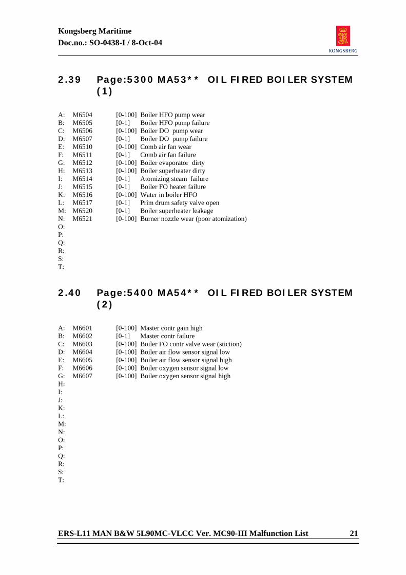
Kongsberg Maritime Doc.no.: SO-0438-I / 8-Oct-04
ERS-L11 MAN B&W 5L90MC-VLCC Ver. MC90-III Malfunction List 21
2.39 Page:5300 MA53** OIL FIRED BOILER SYSTEM (1)
A: M6504 [0-100] Boiler HFO pump wear B: M6505 [0-1] Boiler HFO pump failure C: M6506 [0-100] Boiler DO pump wear D: M6507 [0-1] Boiler DO pump failure E: M6510 [0-100] Comb air fan wear F: M6511 [0-1] Comb air fan failure G: M6512 [0-100] Boiler evaporator dirty H: M6513 [0-100] Boiler superheater dirty I: M6514 [0-1] Atomizing steam failure J: M6515 [0-1] Boiler FO heater failure K: M6516 [0-100] Water in boiler HFO L: M6517 [0-1] Prim drum safety valve open M: M6520 [0-1] Boiler superheater leakage N: M6521 [0-100] Burner nozzle wear (poor atomization) O: P: Q: R: S: T: 2.40 Page:5400 MA54** OIL FIRED BOILER SYSTEM
(2)
A: M6601 [0-100] Master contr gain high B: M6602 [0-1] Master contr failure C: M6603 [0-100] Boiler FO contr valve wear (stiction) D: M6604 [0-100] Boiler air flow sensor signal low E: M6605 [0-100] Boiler air flow sensor signal high F: M6606 [0-100] Boiler oxygen sensor signal low G: M6607 [0-100] Boiler oxygen sensor signal high H: I: J: K: L: M: N: O: P: Q: R: S: T:
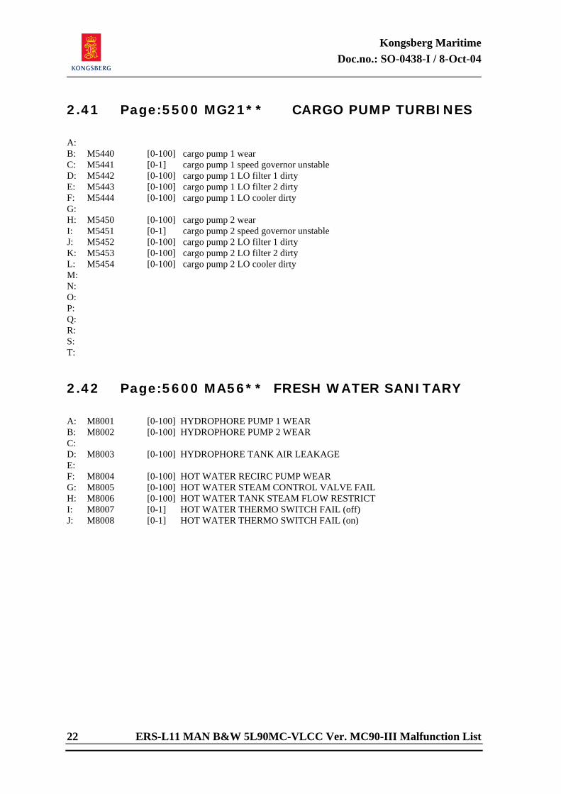
Kongsberg Maritime Doc.no.: SO-0438-I / 8-Oct-04
22 ERS-L11 MAN B&W 5L90MC-VLCC Ver. MC90-III Malfunction List
2.41 Page:5500 MG21** CARGO PUMP TURBINES
A: B: M5440 [0-100] cargo pump 1 wear C: M5441 [0-1] cargo pump 1 speed governor unstable D: M5442 [0-100] cargo pump 1 LO filter 1 dirty E: M5443 [0-100] cargo pump 1 LO filter 2 dirty F: M5444 [0-100] cargo pump 1 LO cooler dirty G: H: M5450 [0-100] cargo pump 2 wear I: M5451 [0-1] cargo pump 2 speed governor unstable J: M5452 [0-100] cargo pump 2 LO filter 1 dirty K: M5453 [0-100] cargo pump 2 LO filter 2 dirty L: M5454 [0-100] cargo pump 2 LO cooler dirty M: N: O: P: Q: R: S: T: 2.42 Page:5600 MA56** FRESH WATER SANITARY
A: M8001 [0-100] HYDROPHORE PUMP 1 WEAR B: M8002 [0-100] HYDROPHORE PUMP 2 WEAR C: D: M8003 [0-100] HYDROPHORE TANK AIR LEAKAGE E: F: M8004 [0-100] HOT WATER RECIRC PUMP WEAR G: M8005 [0-100] HOT WATER STEAM CONTROL VALVE FAIL H: M8006 [0-100] HOT WATER TANK STEAM FLOW RESTRICT I: M8007 [0-1] HOT WATER THERMO SWITCH FAIL (off) J: M8008 [0-1] HOT WATER THERMO SWITCH FAIL (on)
Kongsberg Maritime Doc.no.: SO-0622-H1 / 2-May-05
ERS-L11 MAN B&W 5L90MC-VLCC Ver.MC90-III User's Manual
Engine Room Simulator
ERS-L11 MAN B&W 5L90MC-VLCC Version MC90-III
USER'S MANUAL
Appendix E
Variable List
Doc.no.: SO-0439

Kongsberg Maritime Doc.no.: SO-0439-I / 8-Oct-04
ERS-L11 MAN B&W 5L90MC-VLCC Ver. MC90-III Variable List
Engine Room Simulator
ERS-L11 MAN B&W 5L90MC-VLCC Version MC90-III
VARIABLE LIST
Department/Author: Approved by: Berit Baggerud (s) Arild Hermansen (s)
© 2004 Kongsberg Maritime as All rights reserved
No part of this work covered by the copyright hereon may be reproduced or otherwise copied
without prior permission from Kongsberg Maritime as

Kongsberg Maritime Doc.no.: SO-0439-I / 8-Oct-04
ERS-L11 MAN B&W 5L90MC-VLCC Ver. MC90-III Variable List i
DOCUMENT STATUS Issue No. Date/Year Inc. by Issue No. Date/Year Inc. by SO-0439-A 17.10.95 ASJ/td SO-0439-I 8-Oct-04 HD/beba SO-0439-B 08.07.96 ASJ/td SO-0439-C 21.03.97 ASJ/beba SO-0439-D 25.10.99 AHE/beba SO-0439-E 16.05.00 AHE/beba SO-0439-F 25-Sep-02 AHE/beba SO-0439-G 28-Jan-03 AHE/beba SO-0439-H 10-Jun-03 AHE/beba
CHANGES IN DOCUMENT Issue ECO Paragraph Paragraph Heading/ No. No. No. Description of Change A First issue. B MP38-96 All. Upgrade Variable list to last revision. C MP-1052 All Upgrade Variable list to last revision D MP-1301 All Upgrade Variable list to latest revision E MP-1357 All Upgrade Variable list to latest revision F MP-1431 All Upgrade Variable list to latest revision G MP-1439 All Upgrade Variable list to latest version H MP-1452 All Upgrade Variable list to latest version. I MP-1517 All Upgrade Variable list to latest version
Kongsberg Maritime Doc.no.: SO-0439-I / 8-Oct-04
ii ERS-L11 MAN B&W 5L90MC-VLCC Ver. MC90-III Variable List
<This page is intentionally left blank>
Kongsberg Maritime Doc.no.: SO-0439-I / 8-Oct-04
ERS-L11 MAN B&W 5L90MC-VLCC Ver. MC90-III Variable List iii
TABLE OF CONTENTS
SECTION PAGE
1 DIRECTORY LIST ................................................................................. 1 2 VARIABLE LIST PAGES.......................................................................... 1 2.1 Page:0100 MD01** SEA WATER SYSTEM - PRESS/TEMP ....................... 1 2.2 Page:0101 MD01** SEA WATER SYSTEM - FLOWS ............................... 1 2.3 Page:0102 MD01** SEA WATER SYSTEM - VALVES/PUMPS.................... 1 2.4 Page:0103 MD01** SEA WATER SYSTEM - EMERGENCY / FIRE .............. 1 2.5 Page:0110 MD01** SEA WATER SYSTEM - TEMP CONTROL (1) .............. 1 2.6 Page:0111 MD01** SEA WATER SYSTEM - TEMP CONTROL (2) .............. 1 2.7 Page:0120 MD01** SEA WATER SYSTEM - PUMP POWER ...................... 1 2.8 Page:0190 MD01** CONFIGURABLE PAGE .......................................... 1 2.9 Page:0300 MD03** HFO SERVICE TANK - FLOW/LEVEL......................... 1 2.10 Page:0301 MD03** DFO SERVICE TANK - FLOW/LEVEL ........................ 1 2.11 Page:0302 MD03** FO SERVICE TANK - HEATING............................... 1 2.12 Page:0303 MD03** FO SERVICE TANK - PURIFIER ROUTING ................ 1 2.13 Page:0390 MD03** CONFIGURABLE PAGE .......................................... 1 2.14 Page:0400 MD04** HFO SETTLING TANK 1 ......................................... 1 2.15 Page:0401 MD04** HFO SETTLING TANK 2 ......................................... 1 2.16 Page:0402 MD04** HFO SETTLING TANK 1/2 HEATING ....................... 1 2.17 Page:0490 MD04** CONFIGURABLE PAGE .......................................... 1 2.18 Page:0500 MD05** HFO TRANSFER SYSTEM / SPILL OIL TANK ............. 1 2.19 Page:0501 MD05** BUNKER OIL TANK - AFT....................................... 1 2.20 Page:0502 MD05** BUNKER OIL TANK - PORT .................................... 1 2.21 Page:0503 MD05** BUNKER OIL TANK - STBD .................................... 1 2.22 Page:0504 MD05** BUNKER OIL TANK - FORE .................................... 1 2.23 Page:0590 MD05** CONFIGURABLE PAGE .......................................... 1 2.24 Page:0600 MD06** HFO SEPARATOR 1 - MAIN VARIABLES ................... 1 2.25 Page:0601 MD06** HFO SEPARATOR 1 - FLOW CONTROL ..................... 1 2.26 Page:0602 MD06** HFO SEPARATOR 1 - AUXIL SYSTEMS ..................... 1 2.27 Page:0610 MD06** HFO SEPARATOR 1 - TEMP CONTROL...................... 1 2.28 Page:0611 MD06** HFO SEPARATOR 1 - ALCAP CONTROL .................... 1 2.29 Page:0690 MD06** CONFIGURABLE PAGE .......................................... 1 2.30 Page:0700 MD07** HFO SEPARATOR 2 - MAIN VARIABLES ................... 1 2.31 Page:0701 MD07** HFO SEPARATOR 2 - FLOW CONTROL ..................... 1 2.32 Page:0702 MD07** HFO SEPARATOR 2 - AUXIL SYSTEMS ..................... 1 2.33 Page:0710 MD07** HFO SEPARATOR 2 - TEMP CONTROL...................... 1 2.34 Page:0711 MD07** HFO SEPARATOR 2 - ALCAP CONTROL .................... 1 2.35 Page:0790 MD07** CONFIGURABLE PAGE .......................................... 1 2.36 Page:0800 MD08** DO PURIFIER SYSTEM - MAIN VARIABLES .............. 1 2.37 Page:0801 MD08** DO PURIFIER SYSTEM - FLOW CONTROL................ 1 2.38 Page:0802 MD08** DO PURIFIER SYSTEM - AUXIL VALVES .................. 1 2.39 Page:0810 MD08** DO PURIFIER SYSTEM - TEMP CONTROL ................ 1 2.40 Page:0890 MD08** CONFIGURABLE PAGE .......................................... 1 2.41 Page:0900 MD09** LO PURIFIER SYSTEM - MAIN VARIABLES............... 1 2.42 Page:0901 MD09** LO PURIFIER SYSTEM - FLOW CONTROL ................ 1 2.43 Page:0902 MD09** LO PURIFIER SYSTEM - AUXIL VALVES................... 1 2.44 Page:0910 MD09** LO PURIFIER SYSTEM - TEMP CONTROL ................. 1
Kongsberg Maritime Doc.no.: SO-0439-I / 8-Oct-04
iv ERS-L11 MAN B&W 5L90MC-VLCC Ver. MC90-III Variable List
2.45 Page:0990 MD09** CONFIGURABLE PAGE .......................................... 1 2.46 Page:1000 MD10** ME FW SYSTEM - MAIN VARIABLES ....................... 1 2.47 Page:1001 MD10** ME FW SYSTEM - AUXIL VARIABLES....................... 1 2.48 Page:1002 MD10** ME FW SYSTEM - HTFW FLOWS ............................ 1 2.49 Page:1003 MD10** ME FW SYSTEM - HTFW VALVES / PUMPS................ 1 2.50 Page:1004 MD10** ME FW SYSTEM - LTFW FLOWS.............................. 1 2.51 Page:1005 MD10** ME FW SYSTEM - LTFW VALVES / PUMPS ................ 1 2.52 Page:1006 MD10** ME FW SYSTEM - EXPANSION TANK ....................... 1 2.53 Page:1007 MD10** ME FW SYSTEM - SW ISOLATION........................... 1 2.54 Page:1010 MD10** ME FW SYSTEM - HTFW CONTROL (1) .................... 1 2.55 Page:1011 MD10** ME FW SYSTEM - HTFW CONTROL (2) .................... 1 2.56 Page:1012 MD10** ME FW SYSTEM - LTFW CONTROL (1) ..................... 1 2.57 Page:1013 MD10** ME FW SYSTEM - LTFW CONTROL (2) ..................... 1 2.58 Page:1020 MD10** ME FW SYSTEM - HTFW PUMPS ............................. 1 2.59 Page:1021 MD10** ME FW SYSTEM - LTFW PUMPS .............................. 1 2.60 Page:1022 MD10** ME FW SYSTEM - FW COOLER 1/2.......................... 1 2.61 Page:1090 MD10** CONFIGURABLE PAGE .......................................... 1 2.62 Page:1100 MD11** ME FO SYSTEM - MAIN VARIABLES........................ 1 2.63 Page:1101 MD11** ME FO SYSTEM - HEATING.................................... 1 2.64 Page:1102 MD11** ME FO SYSTEM - BOOSTER PUMPS......................... 1 2.65 Page:1103 MD11** ME FO SYSTEM - SUPPLY PUMPS............................ 1 2.66 Page:1104 MD11** ME FO SYSTEM - VENTING TANK ........................... 1 2.67 Page:1107 MD11** ME FO SYSTEM - FO ISOLATION ............................ 1 2.68 Page:1110 MD11** ME FO SYSTEM - VISCO CONTROL (1) .................... 1 2.69 Page:1111 MD11** ME FO SYSTEM - VISCO CONTROL (2) .................... 1 2.70 Page:1120 MD11** ME FO SYSTEM - FO HEATERS ............................... 1 2.71 Page:1129 MD11** ME FO SYSTEM - FUEL OIL DATA ........................... 1 2.72 Page:1190 MD11** CONFIGURABLE PAGE .......................................... 1 2.73 Page:1200 MD12** ME LO SYSTEM - MAIN VARIABLES........................ 1 2.74 Page:1201 MD12** ME LO SYSTEM - VALVES/PUMPS ........................... 1 2.75 Page:1202 MD12** ME LO SYSTEM - LO SERVICE TANK ....................... 1 2.76 Page:1203 MD12** ME LO SYSTEM - CAM SHAFT LO (1)...................... 1 2.77 Page:1204 MD12** ME LO SYSTEM - CAM SHAFT LO (2)...................... 1 2.78 Page:1205 MD12** ME LO SYSTEM - CYL LUBRICATION ....................... 1 2.79 Page:1207 MD07** ME LO SYSTEM - LO ISOLATION ............................ 1 2.80 Page:1210 MD12** ME LO SYSTEM - LO TEMP CONTROL (1) ................. 1 2.81 Page:1211 MD12** ME LO SYSTEM - LO TEMP CONTROL (2) ................. 1 2.82 Page:1220 MD12** ME LO SYSTEM - MAIN LO PUMPS .......................... 1 2.83 Page:1221 MD12** ME LO SYSTEM - MAIN LO COOLERS ...................... 1 2.84 Page:1290 MD12** CONFIGURABLE PAGE .......................................... 1 2.85 Page:1300 MD13** ME TBCH SYSTEM - TURBOCHARGERS (1)............... 1 2.86 Page:1301 MD13** ME TBCH SYSTEM - TURBOCHARGERS (2)............... 1 2.87 Page:1303 MD13** ME TBCH SYSTEM - CLEANING .............................. 1 2.88 Page:1320 MD13** ME TBCH SYSTEM - AIR COOLER 1......................... 1 2.89 Page:1321 MD13** ME TBCH SYSTEM - AIR COOLER 2......................... 1 2.90 Page:1390 MD13** CONFIGURABLE PAGE .......................................... 1 2.91 Page:1900 MD19** ME CONTROL SYSTEM - LOCAL CONTROL (1) ......... 1 2.92 Page:1901 MD19** ME CONTROL SYSTEM - LOCAL CONTROL (2) ......... 1 2.93 Page:1910 MD19** ME CONTROL SYSTEM - REMOTE CONTROL (1)........ 1 2.94 Page:1911 MD19** ME CONTROL SYSTEM - REMOTE CONTROL (2)........ 1 2.95 Page:1912 MD19** ME CONTROL SYSTEM - REMOTE CONTROL (3)........ 1
Kongsberg Maritime Doc.no.: SO-0439-I / 8-Oct-04
ERS-L11 MAN B&W 5L90MC-VLCC Ver. MC90-III Variable List v
2.96 Page:1913 MD19** ME CONTROL SYSTEM - REMOTE CONTROL (4) ........ 1 2.97 Page:1914 MD19** ME CONTROL SYSTEM - REMOTE CONTROL (5) ........ 1 2.98 Page:1915 MD19** ME CONTROL SYSTEM - REMOTE CONTROL (6) ........ 1 2.99 Page:1920 MD19** ME CONTROL SYSTEM - EMERGENCY CONTROL ....... 1 2.100 Page:1990 MD19** CONFIGURABLE PAGE .......................................... 1 2.101 Page:2000 MD20** ME POWER SYSTEM - MAIN VARIABLES .................. 1 2.102 Page:2001 MD20** ME POWER SYSTEM - CYL EXHAUST TEMP............... 1 2.103 Page:2002 MD20** ME POWER SYSTEM - CYL COOLING ....................... 1 2.104 Page:2003 MD20** ME POWER SYSTEM - CYL METAL TEMP................... 1 2.105 Page:2020 MD20** ME POWER SYSTEM - CYL FUEL PUMPS................... 1 2.106 Page:2090 MD20** CONFIGURABLE PAGE .......................................... 1 2.107 Page:2100 MD21** ME POWER SYSTEM - CYL 1 CONDITION (1)............ 1 2.108 Page:2101 MD21** ME CYL 1 INDICATION RESULT.............................. 1 2.109 Page:2190 MD21** CONFIGURABLE PAGE .......................................... 1 2.110 Page:2200 MD22** ME POWER SYSTEM - CYL 2 CONDITION (1)............ 1 2.111 Page:2201 MD22** ME CYL 2 INDICATION RESULT.............................. 1 2.112 Page:2290 MD22** CONFIGURABLE PAGE .......................................... 1 2.113 Page:2300 MD23** ME POWER SYSTEM - CYL 3 CONDITION (1)............ 1 2.114 Page:2301 MD23** ME CYL 3 INDICATION RESULT.............................. 1 2.115 Page:2390 MD23** CONFIGURABLE PAGE .......................................... 1 2.116 Page:2400 MD24** ME POWER SYSTEM - CYL 4 CONDITION (1)............ 1 2.117 Page:2401 MD24** ME CYL 4 INDICATION RESULT.............................. 1 2.118 Page:2490 MD24** CONFIGURABLE PAGE .......................................... 1 2.119 Page:2500 MD25** ME POWER SYSTEM - CYL 5 CONDITION (1)............ 1 2.120 Page:2501 MD25** ME CYL 5 INDICATION RESULT.............................. 1 2.121 Page:2590 MD25** CONFIGURABLE PAGE .......................................... 1 2.122 Page:2700 MD27** ME PISTON RING MONITOR (1/2) ......................... 1 2.123 Page:2701 MD27** ME PISTON RING MONITOR (2/2) ......................... 1 2.124 Page:2790 MD27** CONFIGURABLE PAGE .......................................... 1 2.125 Page:2900 MD29** ME BEARING SYSTEM - CROSSH/CRANC ................. 1 2.126 Page:2901 MD29** ME BEARING SYSTEM - MAIN /THRUST................... 1 2.127 Page:2990 MD29** CONFIGURABLE PAGE .......................................... 1 2.128 Page:5300 MD53** PROPELLER SERVO OIL SYSTEM (1) ...................... 1 2.129 Page:5301 MD53** PROPELLER SERVO OIL SYSTEM (2) ...................... 1 2.130 Page:5302 MD53** PROPELLER SERVO OIL SYSTEM (3) ...................... 1 2.131 Page:5310 MD53** PROPELLER PITCH CONTROL ................................. 1 2.132 Page:5390 MD53** CONFIGURABLE PAGE .......................................... 1 2.133 Page:5400 MD54** STERN TUBE SYSTEM - GRAVITY TANKS ................. 1 2.134 Page:5401 MD54** STERN TUBE SYSTEM - BEARINGS ......................... 1 2.135 Page:5402 MD54** STERN TUBE SYSTEM - LO COOLER........................ 1 2.136 Page:5490 MD54** CONFIGURABLE PAGE .......................................... 1 2.137 Page:5600 MD56** SHIP PROPULSION SYSTEM - HULL FORCES ............ 1 2.138 Page:5601 MD56** SHIP PROPULSION SYSTEM - STEERING GEAR......... 1 2.139 Page:5610 MD56** SHIP COURSE CONTROL (1) ................................. 1 2.140 Page:5611 MD56** SHIP COURSE CONTROL (2) ................................. 1 2.141 Page:5690 MD56** CONFIGURABLE PAGE .......................................... 1 2.142 Page:5700 MD57** SHIP LOAD CONDITION (1).................................. 1 2.143 Page:5701 MD57** SHIP LOAD CONDITION (2).................................. 1 2.144 Page:5702 MD57** SHIP LOAD CONDITION (3).................................. 1 2.145 Page:5790 MD57** CONFIGURABLE PAGE .......................................... 1 2.146 Page:5800 MD58** SHIP VENTILATION SYSTEMS ETC......................... 1
Kongsberg Maritime Doc.no.: SO-0439-I / 8-Oct-04
vi ERS-L11 MAN B&W 5L90MC-VLCC Ver. MC90-III Variable List
2.147 Page:5801 MD58** SHIP FIRE EXTINGUISHING SYSTEM ...................... 1 2.148 Page:5810 MD58** STEERING GEAR SYSTEM...................................... 1 2.149 Page:5811 MD58** STEERING GEAR SYSTEM...................................... 1 2.150 Page:5812 MD58** STEERING GEAR SYSTEM...................................... 1 2.151 Page:5813 MD58** STEERING GEAR SYSTEM...................................... 1 2.152 Page:5890 MD58** CONFIGURABLE PAGE .......................................... 1 2.153 Page:6000 MD60** START AIR RECEIVER SYSTEM (1) ........................ 1 2.154 Page:6001 MD60** START AIR RECEIVER SYSTEM (2) ........................ 1 2.155 Page:6002 MD60** SERV AIR RECEIVER SYSTEM ............................... 1 2.156 Page:6003 MD60** START AIR COMPRESSOR 1................................... 1 2.157 Page:6004 MD60** START AIR COMPRESSOR 2................................... 1 2.158 Page:6005 MD60** SERVICE AIR COMPRESSOR .................................. 1 2.159 Page:6006 MD60** AIR RECEIVER SAFETY VALVE DATA ....................... 1 2.160 Page:6090 MD60** CONFIGURABLE PAGE .......................................... 1 2.161 Page:6100 MD61** FRESH WATER GENERATOR - EJECTOR SYSTEM....... 1 2.162 Page:6101 MD69** FRESH WATER GENERATOR - SW FEED................... 1 2.163 Page:6102 MD61** FRESH WATER GENERATOR - HEATING................... 1 2.164 Page:6103 MD61** FRESH WATER GENERATOR - COOLING .................. 1 2.165 Page:6104 MD61** FRESH WATER GENERATOR - DISTILLATE ............... 1 2.166 Page:6105 MD61** FRESH WATER GENERATOR - LOAD CONTROL ......... 1 2.167 Page:6107 MD61** FRESH WATER GENERATOR - ISOLATION................ 1 2.168 Page:6190 MD61** CONFIGURABLE PAGE .......................................... 1 2.169 Page:6200 MD62** SLUDGE TANK / INCINERATOR .............................. 1 2.170 Page:6201 MD62** BILGE WELL SYSTEM - LEVELS .............................. 1 2.171 Page:6290 MD62** CONFIGURABLE PAGE .......................................... 1 2.172 Page:6300 MD63** BILGE SEPARATOR (1) ........................................ 1 2.173 Page:6301 MD63** BILGE SEPARATOR (2) ........................................ 1 2.174 Page:6302 MD63** CLEAN BILGE WATER TANK................................... 1 2.175 Page:6390 MD63** CONFIGURABLE PAGE .......................................... 1 2.176 Page:6400 MD64** REFRIG SYSTEM - COMPRESSOR ........................... 1 2.177 Page:6401 MD64** REFRIG SYSTEM - CONDENSER ............................. 1 2.178 Page:6402 MD64** REFRIG SYS -EVAPORATOR CARGO H / PROV S ....... 1 2.179 Page:6403 MD64** REFRIG SYSTEM - LIQUID RECEIVER...................... 1 2.180 Page:6404 MD64** REFRIG SYSTEM - COMPR LO SYSTEM .................... 1 2.181 Page:6405 MD64** REFRIG SYSTEM - SW SUPPLY ............................... 1 2.182 Page:6406 MD64** REFRIG SYSTEM - MISCELLANEOUS ....................... 1 2.183 Page:6410 MD64** REFRIG SYSTEM - CAPACITY CONTROL................... 1 2.184 Page:6420 MD64** REFRIG SYSTEM -CARGO HOLD / HEAT FLUXES ....... 1 2.185 Page:6421 MD64** REFRIG SYSTEM -PROV STORE / HEAT FLUXES........ 1 2.186 Page:6422 MD64** REFRIG SYSTEM - PERFORMANCE .......................... 1 2.187 Page:6490 MD64** CONFIGURABLE PAGE .......................................... 1 2.188 Page:6500 MD65** WASTE HEAT RECOVERY - THERMAL OIL CIRC......... 1 2.189 Page:6501 MD65** WASTE HEAT RECOVERY - SERV TANK HEATING..... 1 2.190 Page:6502 MD65** WASTE HEAT RECOVERY - SETTL TANK HEATING..... 1 2.191 Page:6503 MD65** WASTE HEAT RECOVERY - BUNKER TANK HEATING.. 1 2.192 Page:6510 MD65** WASTE HEAT RECOVERY - TO COOLER ................... 1 2.193 Page:6511 MD65** WASTE HEAT RECOVERY - RECIRC CONTROL .......... 1 2.194 Page:6520 MD65** WASTE HEAT RECOVERY - AIR COOLERS ................ 1 2.195 Page:6521 MD65** WASTE HEAT RECOVERY - HEAT TRANSFER ............ 1 2.196 Page:6590 MD65** CONFIGURABLE PAGE .......................................... 1 2.197 Page:6700 MD67** FRESH W SANITARY - HYDROPHORE PUMPS............ 1
Kongsberg Maritime Doc.no.: SO-0439-I / 8-Oct-04
ERS-L11 MAN B&W 5L90MC-VLCC Ver. MC90-III Variable List vii
2.198 Page:6701 MD67** FRESH W SANITARY - HYDROPHORE TANK.............. 1 2.199 Page:6702 MD67** FRESH W SANITARY - HYDROPHORE TANK.............. 1 2.200 Page:6703 MD67** FRESH W SANITARY - HOT WATER TANK ................ 1 2.201 Page:6704 MD67** FRESH W SANITARY - HEAT CONTROL .................... 1 2.202 Page:6705 MD67** FRESH W SANITARY - CONSUME............................ 1 2.203 Page:6790 MD67** CONFIGURABLE PAGE .......................................... 1 2.204 Page:7000 MD70** ELECTRIC POWER PLANT - MAIN VARIABLES ........... 1 2.205 Page:7001 MD70** ELECTRIC POWER PLANT - DG 1 ............................ 1 2.206 Page:7002 MD70** ELECTRIC POWER PLANT - DG 2 ............................ 1 2.207 Page:7003 MD70** ELECTRIC POWER PLANT - TG ............................... 1 2.208 Page:7004 MD70** ELECTRIC POWER PLANT - SG ............................... 1 2.209 Page:7005 MD70** ELECTRIC POWER PLANT - SEMIAUTO SYNCH.......... 1 2.210 Page:7006 MD70** ELECTRIC POWER PLANT - EG / SHORE CONNECT.... 1 2.211 Page:7007 MD70** ELECTRIC POWER PLANT - MISCELLANEOUS ........... 1 2.212 Page:7008 MD70** ELECTRIC POWER PLANT - CIRCUIT BREAKERS........ 1 2.213 Page:7010 MD70** POWER CHIEF - GENERATOR LOGIC (1).................. 1 2.214 Page:7011 MD70** POWER CHIEF - GENERATOR LOGIC (2).................. 1 2.215 Page:7012 MD70** POWER CHIEF - GEN CONTROL DATA (1) ................ 1 2.216 Page:7013 MD70** POWER CHIEF - GEN CONTROL DATA (2) ................ 1 2.217 Page:7020 MD70** POWER CHIEF - PUMP CONTROL (1)....................... 1 2.218 Page:7021 MD70** POWER CHIEF - PUMP CONTROL (2)....................... 1 2.219 Page:7022 MD70** POWER CHIEF - PUMP CONTROL (3)....................... 1 2.220 Page:7023 MD70** POWER CHIEF - PUMP STBY DATA.......................... 1 2.221 Page:7024 MD70** POWER CHIEF - PUMP CONTROL DATA ................... 1 2.222 Page:7025 MD70** POWER CHIEF - PURIFIER CONTROL DATA .............. 1 2.223 Page:7090 MD70** CONFIGURABLE PAGE .......................................... 1 2.224 Page:7100 MD71** DIESELGENERATOR 1 - MAIN VARIABLES................ 1 2.225 Page:7101 MD71** DIESELGENERATOR 1 - FW SYSTEM ....................... 1 2.226 Page:7102 MD71** DIESELGENERATOR 1 - LO SYSTEM........................ 1 2.227 Page:7103 MD71** DIESELGENERATOR 1 - FO SYSTEM........................ 1 2.228 Page:7104 MD71** DIESELGENERATOR 1 - SW SYSTEM....................... 1 2.229 Page:7105 MD71** DIESELGENERATOR 1 - ENGINE PROTECTION.......... 1 2.230 Page:7110 MD71** DIESELGENERATOR 1 - SPEED CONTROLLER........... 1 2.231 Page:7111 MD71** DIESELGENERATOR 1 - TEMP CONTROLLER............ 1 2.232 Page:7190 MD71** CONFIGURABLE PAGE .......................................... 1 2.233 Page:7200 MD72** DIESELGENERATOR 2 - MAIN VARIABLES................ 1 2.234 Page:7201 MD72** DIESELGENERATOR 2 - FW SYSTEM ....................... 1 2.235 Page:7202 MD72** DIESELGENERATOR 2 - LO SYSTEM........................ 1 2.236 Page:7203 MD72** DIESELGENERATOR 2 - FO SYSTEM........................ 1 2.237 Page:7204 MD72** DIESELGENERATOR 2 - SW SYSTEM....................... 1 2.238 Page:7205 MD72** DIESELGENERATOR 2 - ENGINE PROTECTION.......... 1 2.239 Page:7210 MD72** DIESELGENERATOR 2 - SPEED CONTROLLER........... 1 2.240 Page:7211 MD72** DIESELGENERATOR 2 - TEMP CONTROLLER............ 1 2.241 Page:7290 MD72** CONFIGURABLE PAGE .......................................... 1 2.242 Page:7300 MD73** SHAFTGENERATOR - PTI / PTO (1) ........................ 1 2.243 Page:7301 MD73** SHAFTGENERATOR - PTI / PTO (2) ........................ 1 2.244 Page:7307 MD73** SHAFTGENERATOR - ISOLATION............................ 1 2.245 Page:7310 MD73** SHAFTGENERATOR - PTI CONTROL ........................ 1 2.246 Page:7330 MD73** SHAFTGENERATOR - MISC .................................... 1 2.247 Page:7390 MD73** CONFIGURABLE PAGE .......................................... 1 2.248 Page:8000 MD80** STEAM PLANT - MAIN VARIABLES ......................... 1
Kongsberg Maritime Doc.no.: SO-0439-I / 8-Oct-04
viii ERS-L11 MAN B&W 5L90MC-VLCC Ver. MC90-III Variable List
2.249 Page:8001 MD80** STEAM PLANT - FEEDW SUPPLY ........................... 1 2.250 Page:8002 MD80** STEAM PLANT - MISC VALVES .............................. 1 2.251 Page:8003 MD80** STEAM PLANT - DRAIN/VENTING .......................... 1 2.252 Page:8004 MD80** STEAM PLANT - FEED WATER TANK....................... 1 2.253 Page:8005 MD80** STEAM PLANT - DISTILLED FW TANK..................... 1 2.254 Page:8006 MD80** STEAM PLANT - SAFETY VALVES ........................... 1 2.255 Page:8007 MD80** STEAM PLANT - ISOLATION.................................. 1 2.256 Page:8010 MD80** STEAM PLANT - LEVEL CONTROL (1) ..................... 1 2.257 Page:8011 MD80** STEAM PLANT - LEVEL CONTROL (2) ..................... 1 2.258 Page:8090 MD80** CONFIGURABLE PAGE .......................................... 1 2.259 Page:8100 MD81** EXHAUST BOILER - MAIN VARIABLES ..................... 1 2.260 Page:8101 MD81** EXHAUST BOILER - CIRC PUMPS............................ 1 2.261 Page:8107 MD81** EXHAUST BOILER - ISOLATION ............................. 1 2.262 Page:8110 MD81** EXHAUST BOILER - PRESS CONTROL (1) ................ 1 2.263 Page:8111 MD81** EXHAUST BOILER - PRESS CONTROL (2) ................ 1 2.264 Page:8120 MD81** EXHAUST BOILER - HEAT TRANSFER ...................... 1 2.265 Page:8121 MD81** EXHAUST BOILER - SOOTBLOWING........................ 1 2.266 Page:8190 MD81** CONFIGURABLE PAGE .......................................... 1 2.267 Page:8200 MD82** STEAM GENERATOR - MAIN VARIABLES.................. 1 2.268 Page:8201 MD82** STEAM GENERATOR - STEAM FLOWS...................... 1 2.269 Page:8207 MD82** STEAM GENERATOR - STEAM ISOLATION................ 1 2.270 Page:8290 MD82** CONFIGURABLE PAGE .......................................... 1 2.271 Page:8300 MD83** OIL FIRED BOILER - MAIN VARIABLES.................... 1 2.272 Page:8301 MD83** OIL FIRED BOILER - AUXIL VARIABLES................... 1 2.273 Page:8320 MD83** OIL FIRED BOILER - HEAT TRANSFER..................... 1 2.274 Page:8390 MD83** CONFIGURABLE PAGE .......................................... 1 2.275 Page:8400 MD84** OIL FIRED BOILER - FUEL OIL SUPPLY.................... 1 2.276 Page:8401 MD84** OIL FIRED BOILER - COMBUSTION AIR SUPPLY ....... 1 2.277 Page:8402 MD84** OIL FIRED BOILER - BURNER MANAGEMENT (1) ...... 1 2.278 Page:8403 MD84** OIL FIRED BOILER - BURNER MANAGEMENT (2) ...... 1 2.279 Page:8410 MD84** OIL FIRED BOILER - MASTER CONTROL .................. 1 2.280 Page:8411 MD84** OIL FIRED BOILER - FO SLAVE CONTROL ............... 1 2.281 Page:8412 MD84** OIL FIRED BOILER - AIR SLAVE CONTROL............... 1 2.282 Page:8413 MD84** OIL FIRED BOILER - OXYGEN CONTROL.................. 1 2.283 Page:8414 MD84** OIL FIRED BOILER - MASTER CONTROL DATA.......... 1 2.284 Page:8415 MD84** OIL FIRED BOILER - LOW SETTINGS ...................... 1 2.285 Page:8416 MD84** OIL FIRED BOILER - HIGH SETTINGS ..................... 1 2.286 Page:8490 MD84** CONFIGURABLE PAGE .......................................... 1 2.287 Page:8500 MD85** STEAM CONDENSER - MAIN VARIABLES ................. 1 2.288 Page:8501 MD85** STEAM CONDENSER - HEAT TRANSFER .................. 1 2.289 Page:8590 MD85** CONFIGURABLE PAGE .......................................... 1 2.290 Page:8600 MD86** TURBO GENERATOR - STEAM SYSTEM (1)............... 1 2.291 Page:8601 MD86** TURBO GENERATOR - STEAM SYSTEM (2)............... 1 2.292 Page:8602 MD86** TURBO GENERATOR - LO SYSTEM.......................... 1 2.293 Page:8607 MD86** TURBO GENERATOR - ISOLATION .......................... 1 2.294 Page:8610 MD86** TURBO GENERATOR - SPEED CONTROL (1) ............. 1 2.295 Page:8611 MD86** TURBO GENERATOR - SPEED CONTROL (2) ............. 1 2.296 Page:8690 MD86** CONFIGURABLE PAGE .......................................... 1 2.297 Page:8700 MD87** CARGO PUMP TURBINE 1 (1 of 3)....................... 1 2.298 Page:8701 MD87** CARGO PUMP TURBINE 1 (2 of 3)....................... 1 2.299 Page:8702 MD87** CARGO PUMP TURBINE 1 (3 of 3)....................... 1
Kongsberg Maritime Doc.no.: SO-0439-I / 8-Oct-04
ERS-L11 MAN B&W 5L90MC-VLCC Ver. MC90-III Variable List ix
2.300 Page:8703 MD87** CARGO PUMP TURBINE 2 (1 of 3)....................... 1 2.301 Page:8704 MD87** CARGO PUMP TURBINE 2 (2 of 3)....................... 1 2.302 Page:8705 MD87** CARGO PUMP TURBINE 2 (3 of 3)....................... 1 2.303 Page:8710 MD87** CARGO PUMP TURBINE SPEED CONTROL ............ 1 2.304 Page:8790 MD87** CONFIGURABLE PAGE .......................................... 1 2.305 Page:8900 MD89** INERT GAS GENERATOR (1) ................................. 1 2.306 Page:8901 MD89** INERT GAS GENERATOR (2) ................................. 1 2.307 Page:8990 MD89** CONFIGURABLE PAGE .......................................... 1 2.308 Page:9000 MD90** SIM CONTROL : PROCESS DYNAMICS..................... 1 2.309 Page:9001 MD90** SIM CONTROL : ISOLATIONS ................................ 1 2.310 Page:9002 MD90** SIM CONTROL : EXTERNAL CONDITIONS ................ 1 2.311 Page:9003 MD90** SIM CONTROL : AIR / STEAM / EL LOADS ............... 1 2.312 Page:9004 MD90** SIM CONTROL : LOG SETTING............................... 1 2.313 Page:9005 MD90** SIM CONTROL : MISCELLANEOUS .......................... 1 2.314 Page:9006 MD90** SIM CONTROL : AUTO PULSAR SYSTEM .................. 1 2.315 Page:9007 MD90** SIM CONTROL : TRIP STATE SURVEY (1) ................ 1 2.316 Page:9008 MD90** SIM CONTROL : TRIP STATE SURVEY (2) ................ 1 2.317 Page:9010 MD90** SIM CONTROL : ME BRIDGE CONTROL (1) .............. 1 2.318 Page:9011 MD90** SIM CONTROL : ME BRIDGE CONTROL (2) .............. 1 2.319 Page:9020 MD90** SIM CONTROL : DIRECT LEVEL ADJUST .................. 1 2.320 Page:9090 MD90** CONFIGURABLE PAGE .......................................... 1 2.321 Page:9300 MD93** SCENARIO - FREE TAGS ....................................... 1 2.322 Page:9390 MD93** CONFIGURABLE PAGE .......................................... 1

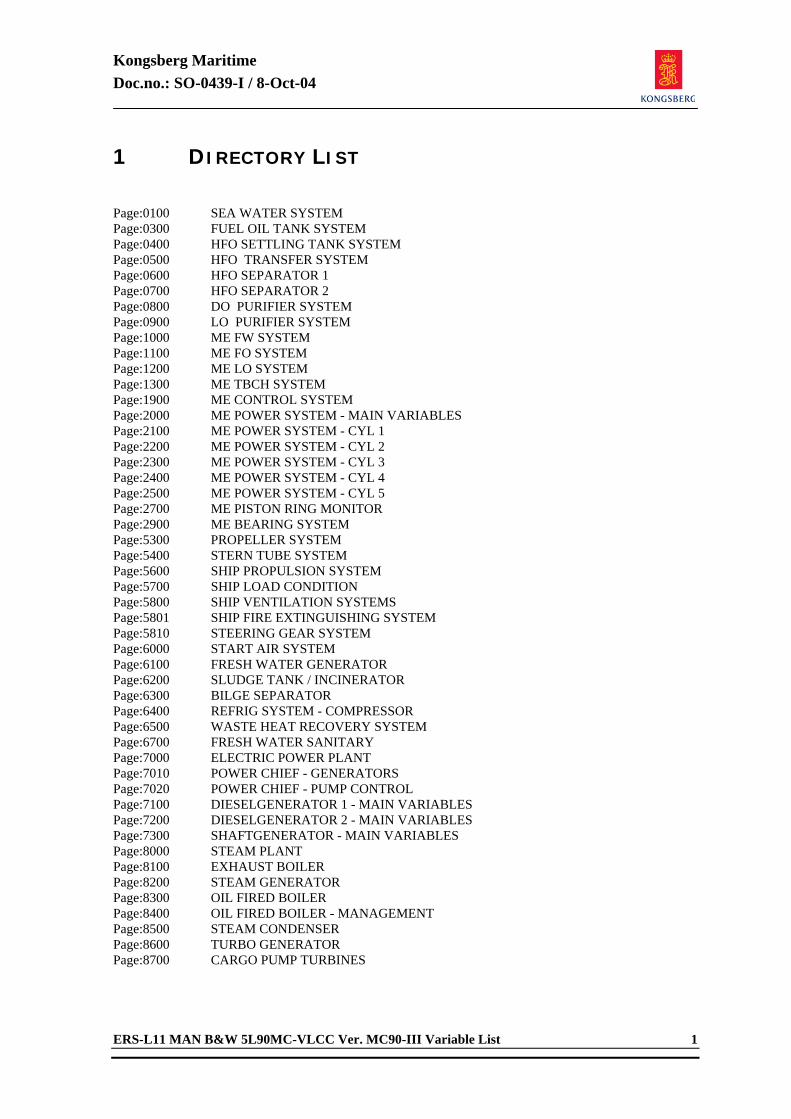
Kongsberg Maritime Doc.no.: SO-0439-I / 8-Oct-04
ERS-L11 MAN B&W 5L90MC-VLCC Ver. MC90-III Variable List 1
1 DIRECTORY LIST Page:0100 SEA WATER SYSTEM Page:0300 FUEL OIL TANK SYSTEM Page:0400 HFO SETTLING TANK SYSTEM Page:0500 HFO TRANSFER SYSTEM Page:0600 HFO SEPARATOR 1 Page:0700 HFO SEPARATOR 2 Page:0800 DO PURIFIER SYSTEM Page:0900 LO PURIFIER SYSTEM Page:1000 ME FW SYSTEM Page:1100 ME FO SYSTEM Page:1200 ME LO SYSTEM Page:1300 ME TBCH SYSTEM Page:1900 ME CONTROL SYSTEM Page:2000 ME POWER SYSTEM - MAIN VARIABLES Page:2100 ME POWER SYSTEM - CYL 1 Page:2200 ME POWER SYSTEM - CYL 2 Page:2300 ME POWER SYSTEM - CYL 3 Page:2400 ME POWER SYSTEM - CYL 4 Page:2500 ME POWER SYSTEM - CYL 5 Page:2700 ME PISTON RING MONITOR Page:2900 ME BEARING SYSTEM Page:5300 PROPELLER SYSTEM Page:5400 STERN TUBE SYSTEM Page:5600 SHIP PROPULSION SYSTEM Page:5700 SHIP LOAD CONDITION Page:5800 SHIP VENTILATION SYSTEMS Page:5801 SHIP FIRE EXTINGUISHING SYSTEM Page:5810 STEERING GEAR SYSTEM Page:6000 START AIR SYSTEM Page:6100 FRESH WATER GENERATOR Page:6200 SLUDGE TANK / INCINERATOR Page:6300 BILGE SEPARATOR Page:6400 REFRIG SYSTEM - COMPRESSOR Page:6500 WASTE HEAT RECOVERY SYSTEM Page:6700 FRESH WATER SANITARY Page:7000 ELECTRIC POWER PLANT Page:7010 POWER CHIEF - GENERATORS Page:7020 POWER CHIEF - PUMP CONTROL Page:7100 DIESELGENERATOR 1 - MAIN VARIABLES Page:7200 DIESELGENERATOR 2 - MAIN VARIABLES Page:7300 SHAFTGENERATOR - MAIN VARIABLES Page:8000 STEAM PLANT Page:8100 EXHAUST BOILER Page:8200 STEAM GENERATOR Page:8300 OIL FIRED BOILER Page:8400 OIL FIRED BOILER - MANAGEMENT Page:8500 STEAM CONDENSER Page:8600 TURBO GENERATOR Page:8700 CARGO PUMP TURBINES
Kongsberg Maritime Doc.no.: SO-0439-I / 8-Oct-04
2 ERS-L11 MAN B&W 5L90MC-VLCC Ver. MC90-III Variable List
Page:8900 INERT GAS GENERATOR Page:9000 SIM CONTROL Page:9300 SCENARIO - FREE TAGS
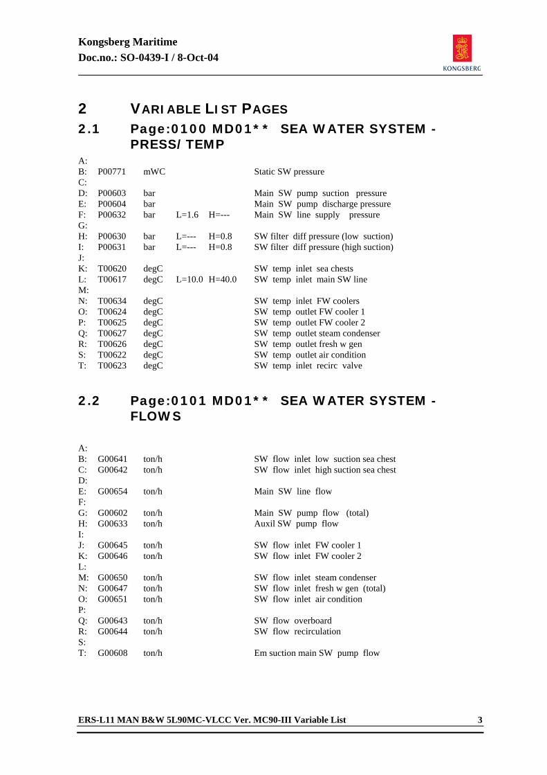
Kongsberg Maritime Doc.no.: SO-0439-I / 8-Oct-04
ERS-L11 MAN B&W 5L90MC-VLCC Ver. MC90-III Variable List 3
2 VARIABLE LIST PAGES 2.1 Page:0100 MD01** SEA WATER SYSTEM -
PRESS/TEMP A: B: P00771 mWC Static SW pressure C: D: P00603 bar Main SW pump suction pressure E: P00604 bar Main SW pump discharge pressure F: P00632 bar L=1.6 H=--- Main SW line supply pressure G: H: P00630 bar L=--- H=0.8 SW filter diff pressure (low suction) I: P00631 bar L=--- H=0.8 SW filter diff pressure (high suction) J: K: T00620 degC SW temp inlet sea chests L: T00617 degC L=10.0 H=40.0 SW temp inlet main SW line M: N: T00634 degC SW temp inlet FW coolers O: T00624 degC SW temp outlet FW cooler 1 P: T00625 degC SW temp outlet FW cooler 2 Q: T00627 degC SW temp outlet steam condenser R: T00626 degC SW temp outlet fresh w gen S: T00622 degC SW temp outlet air condition T: T00623 degC SW temp inlet recirc valve 2.2 Page:0101 MD01** SEA WATER SYSTEM -
FLOWS
A: B: G00641 ton/h SW flow inlet low suction sea chest C: G00642 ton/h SW flow inlet high suction sea chest D: E: G00654 ton/h Main SW line flow F: G: G00602 ton/h Main SW pump flow (total) H: G00633 ton/h Auxil SW pump flow I: J: G00645 ton/h SW flow inlet FW cooler 1 K: G00646 ton/h SW flow inlet FW cooler 2 L: M: G00650 ton/h SW flow inlet steam condenser N: G00647 ton/h SW flow inlet fresh w gen (total) O: G00651 ton/h SW flow inlet air condition P: Q: G00643 ton/h SW flow overboard R: G00644 ton/h SW flow recirculation S: T: G00608 ton/h Em suction main SW pump flow
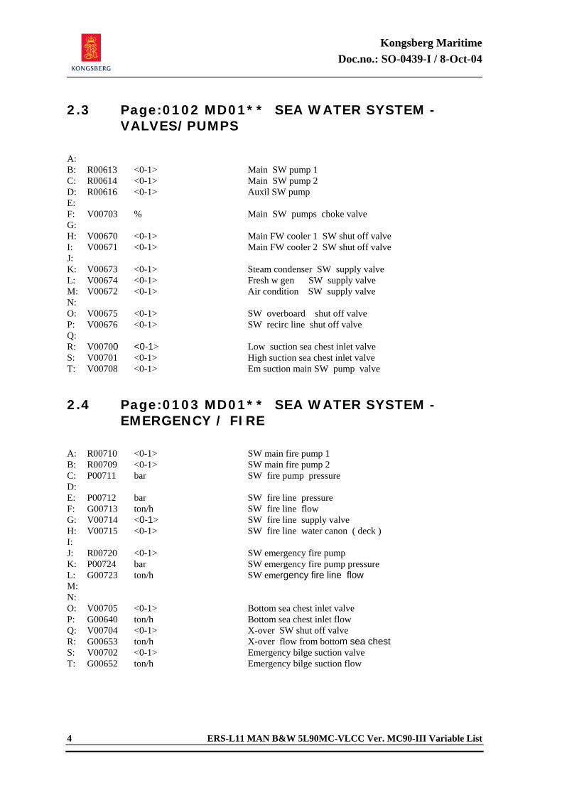
Kongsberg Maritime Doc.no.: SO-0439-I / 8-Oct-04
4 ERS-L11 MAN B&W 5L90MC-VLCC Ver. MC90-III Variable List
2.3 Page:0102 MD01** SEA WATER SYSTEM - VALVES/PUMPS
A: B: R00613 <0-1> Main SW pump 1 C: R00614 <0-1> Main SW pump 2 D: R00616 <0-1> Auxil SW pump E: F: V00703 % Main SW pumps choke valve G: H: V00670 <0-1> Main FW cooler 1 SW shut off valve I: V00671 <0-1> Main FW cooler 2 SW shut off valve J: K: V00673 <0-1> Steam condenser SW supply valve L: V00674 <0-1> Fresh w gen SW supply valve M: V00672 <0-1> Air condition SW supply valve N: O: V00675 <0-1> SW overboard shut off valve P: V00676 <0-1> SW recirc line shut off valve Q: R: V00700 <0-1> Low suction sea chest inlet valve S: V00701 <0-1> High suction sea chest inlet valve T: V00708 <0-1> Em suction main SW pump valve 2.4 Page:0103 MD01** SEA WATER SYSTEM -
EMERGENCY / FIRE
A: R00710 <0-1> SW main fire pump 1 B: R00709 <0-1> SW main fire pump 2 C: P00711 bar SW fire pump pressure D: E: P00712 bar SW fire line pressure F: G00713 ton/h SW fire line flow G: V00714 <0-1> SW fire line supply valve H: V00715 <0-1> SW fire line water canon ( deck ) I: J: R00720 <0-1> SW emergency fire pump K: P00724 bar SW emergency fire pump pressure L: G00723 ton/h SW emergency fire line flow M: N: O: V00705 <0-1> Bottom sea chest inlet valve P: G00640 ton/h Bottom sea chest inlet flow Q: V00704 <0-1> X-over SW shut off valve R: G00653 ton/h X-over flow from bottom sea chest S: V00702 <0-1> Emergency bilge suction valve T: G00652 ton/h Emergency bilge suction flow
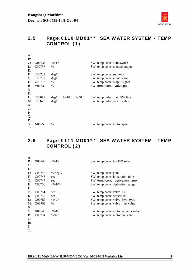
Kongsberg Maritime Doc.no.: SO-0439-I / 8-Oct-04
ERS-L11 MAN B&W 5L90MC-VLCC Ver. MC90-III Variable List 5
2.5 Page:0110 MD01** SEA WATER SYSTEM - TEMP CONTROL (1)
A: B: C: X00736 <0-1> SW temp contr auto switch D: Z00737 % SW temp contr manual output E: F: T00731 degC SW temp contr set point G: T00732 degC SW temp contr input signal H: Z00733 % SW temp contr output signal I: V00730 % SW temp contr valve pos J: K: L: T00617 degC L=10.0 H=40.0 SW temp inlet main SW line M: T00623 degC SW temp inlet recirc valve N: O: P: Q: R: S: N00755 % SW temp contr motor speed T: 2.6 Page:0111 MD01** SEA WATER SYSTEM - TEMP
CONTROL (2)
A: B: X00742 <0-1> SW temp contr hw PID select C: D: E: C00745 %/degC SW temp contr gain F: C00746 sec SW temp contr integration time G: C00747 sec SW temp contr derivation time H: C00750 <0-10> SW temp contr derivation range I: J: C00751 sec SW temp contr valve TC K: C00752 sec SW temp contr sensor TC L: X00753 <0-2> SW temp contr valve hyst type M: X00758 % SW temp contr valve hyst value N: O: X00743 <0-1> SW temp contr motor actuator select P: C00754 %/sec SW temp contr motor constant Q: R: S: T:
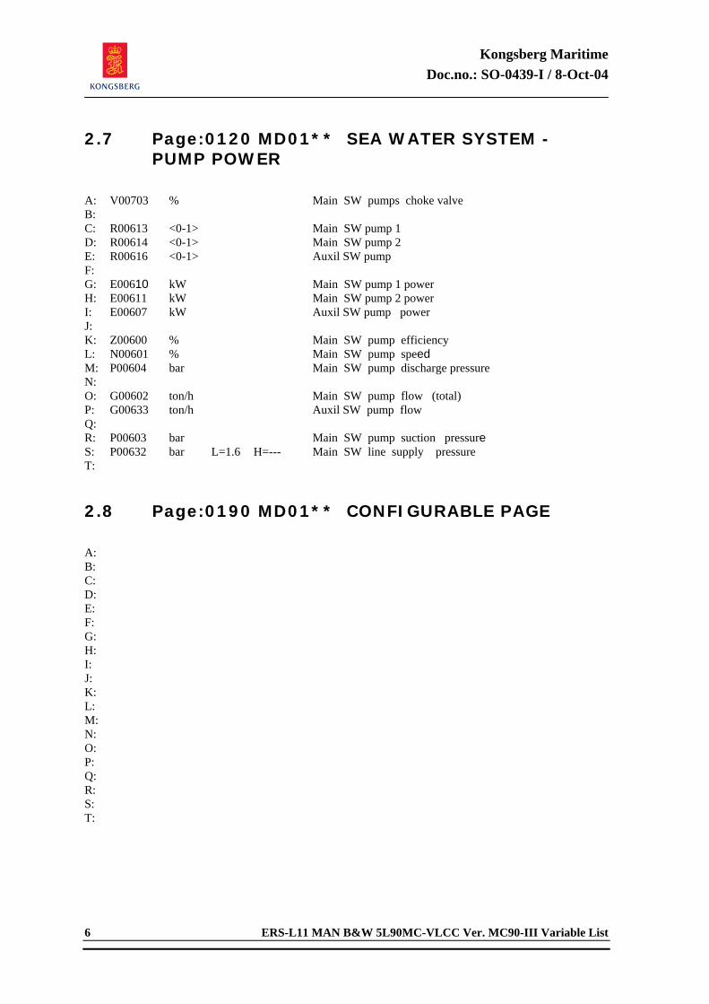
Kongsberg Maritime Doc.no.: SO-0439-I / 8-Oct-04
6 ERS-L11 MAN B&W 5L90MC-VLCC Ver. MC90-III Variable List
2.7 Page:0120 MD01** SEA WATER SYSTEM - PUMP POWER
A: V00703 % Main SW pumps choke valve B: C: R00613 <0-1> Main SW pump 1 D: R00614 <0-1> Main SW pump 2 E: R00616 <0-1> Auxil SW pump F: G: E00610 kW Main SW pump 1 power H: E00611 kW Main SW pump 2 power I: E00607 kW Auxil SW pump power J: K: Z00600 % Main SW pump efficiency L: N00601 % Main SW pump speed M: P00604 bar Main SW pump discharge pressure N: O: G00602 ton/h Main SW pump flow (total) P: G00633 ton/h Auxil SW pump flow Q: R: P00603 bar Main SW pump suction pressure S: P00632 bar L=1.6 H=--- Main SW line supply pressure T: 2.8 Page:0190 MD01** CONFIGURABLE PAGE
A: B: C: D: E: F: G: H: I: J: K: L: M: N: O: P: Q: R: S: T:
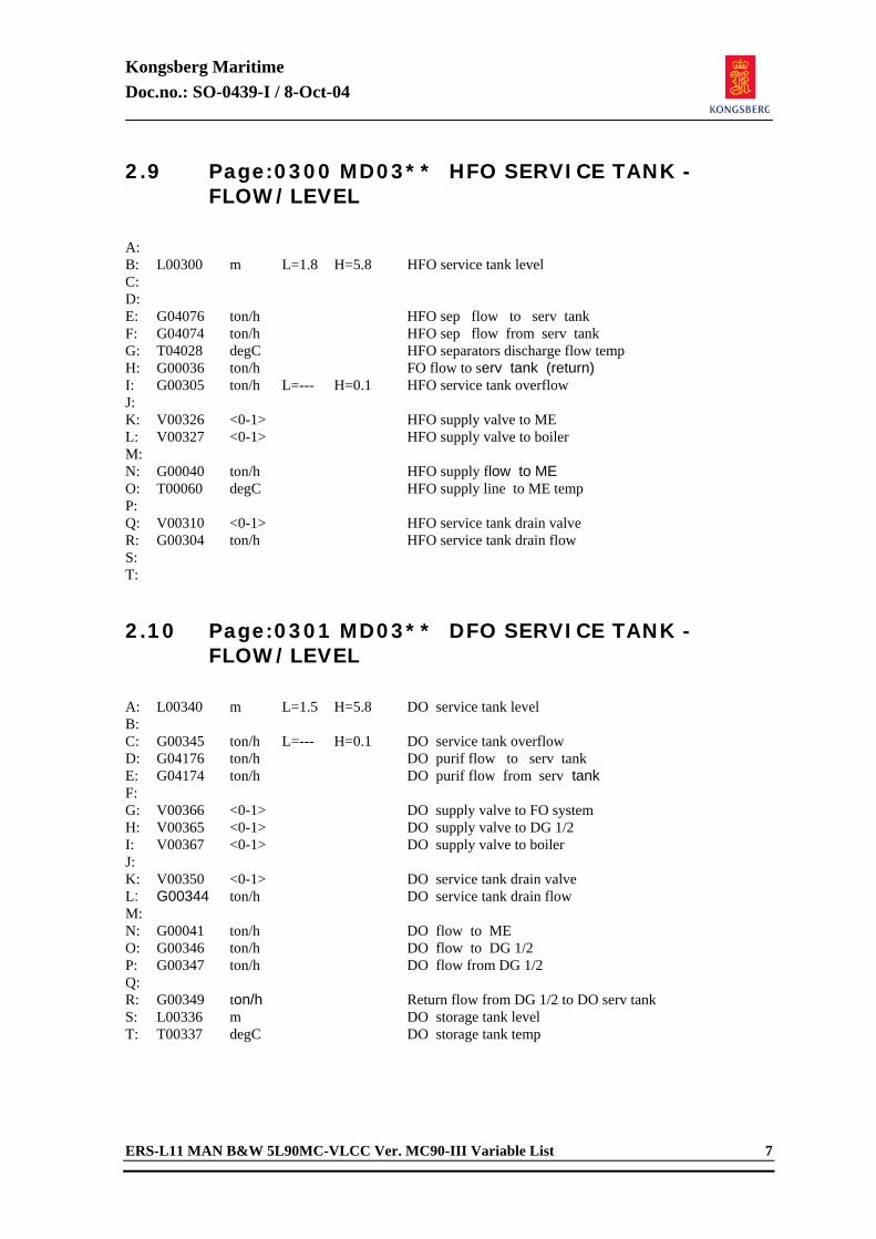
Kongsberg Maritime Doc.no.: SO-0439-I / 8-Oct-04
ERS-L11 MAN B&W 5L90MC-VLCC Ver. MC90-III Variable List 7
2.9 Page:0300 MD03** HFO SERVICE TANK - FLOW/LEVEL
A: B: L00300 m L=1.8 H=5.8 HFO service tank level C: D: E: G04076 ton/h HFO sep flow to serv tank F: G04074 ton/h HFO sep flow from serv tank G: T04028 degC HFO separators discharge flow temp H: G00036 ton/h FO flow to serv tank (return) I: G00305 ton/h L=--- H=0.1 HFO service tank overflow J: K: V00326 <0-1> HFO supply valve to ME L: V00327 <0-1> HFO supply valve to boiler M: N: G00040 ton/h HFO supply flow to ME O: T00060 degC HFO supply line to ME temp P: Q: V00310 <0-1> HFO service tank drain valve R: G00304 ton/h HFO service tank drain flow S: T: 2.10 Page:0301 MD03** DFO SERVICE TANK -
FLOW/LEVEL
A: L00340 m L=1.5 H=5.8 DO service tank level B: C: G00345 ton/h L=--- H=0.1 DO service tank overflow D: G04176 ton/h DO purif flow to serv tank E: G04174 ton/h DO purif flow from serv tank F: G: V00366 <0-1> DO supply valve to FO system H: V00365 <0-1> DO supply valve to DG 1/2 I: V00367 <0-1> DO supply valve to boiler J: K: V00350 <0-1> DO service tank drain valve L: G00344 ton/h DO service tank drain flow M: N: G00041 ton/h DO flow to ME O: G00346 ton/h DO flow to DG 1/2 P: G00347 ton/h DO flow from DG 1/2 Q: R: G00349 ton/h Return flow from DG 1/2 to DO serv tank S: L00336 m DO storage tank level T: T00337 degC DO storage tank temp
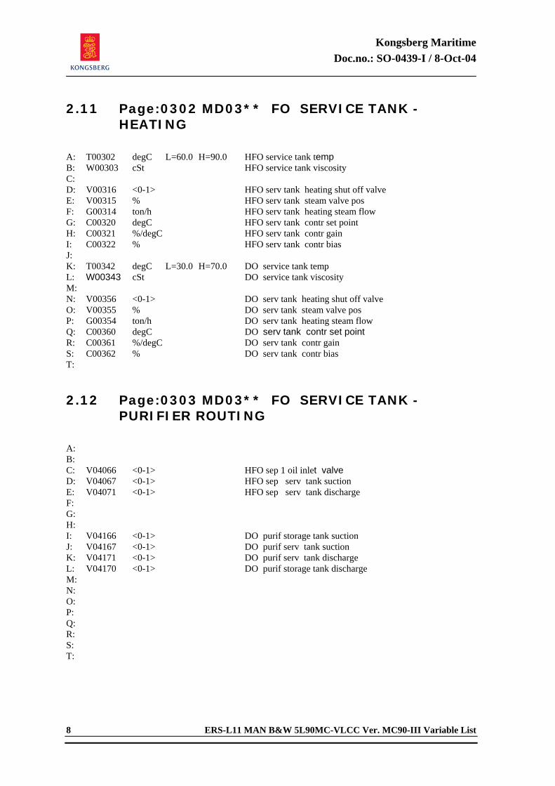
Kongsberg Maritime Doc.no.: SO-0439-I / 8-Oct-04
8 ERS-L11 MAN B&W 5L90MC-VLCC Ver. MC90-III Variable List
2.11 Page:0302 MD03** FO SERVICE TANK - HEATING
A: T00302 degC L=60.0 H=90.0 HFO service tank temp B: W00303 cSt HFO service tank viscosity C: D: V00316 <0-1> HFO serv tank heating shut off valve E: V00315 % HFO serv tank steam valve pos F: G00314 ton/h HFO serv tank heating steam flow G: C00320 degC HFO serv tank contr set point H: C00321 %/degC HFO serv tank contr gain I: C00322 % HFO serv tank contr bias J: K: T00342 degC L=30.0 H=70.0 DO service tank temp L: W00343 cSt DO service tank viscosity M: N: V00356 <0-1> DO serv tank heating shut off valve O: V00355 % DO serv tank steam valve pos P: G00354 ton/h DO serv tank heating steam flow Q: C00360 degC DO serv tank contr set point R: C00361 %/degC DO serv tank contr gain S: C00362 % DO serv tank contr bias T: 2.12 Page:0303 MD03** FO SERVICE TANK -
PURIFIER ROUTING
A: B: C: V04066 <0-1> HFO sep 1 oil inlet valve D: V04067 <0-1> HFO sep serv tank suction E: V04071 <0-1> HFO sep serv tank discharge F: G: H: I: V04166 <0-1> DO purif storage tank suction J: V04167 <0-1> DO purif serv tank suction K: V04171 <0-1> DO purif serv tank discharge L: V04170 <0-1> DO purif storage tank discharge M: N: O: P: Q: R: S: T:
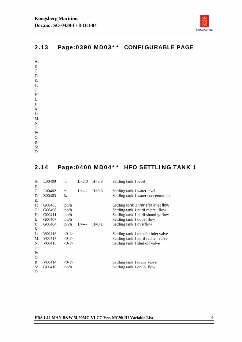
Kongsberg Maritime Doc.no.: SO-0439-I / 8-Oct-04
ERS-L11 MAN B&W 5L90MC-VLCC Ver. MC90-III Variable List 9
2.13 Page:0390 MD03** CONFIGURABLE PAGE
A: B: C: D: E: F: G: H: I: J: K: L: M: N: O: P: Q: R: S: T: 2.14 Page:0400 MD04** HFO SETTLING TANK 1
A: L00400 m L=2.0 H=5.8 Settling tank 1 level B: C: L00402 m L=--- H=0.8 Settling tank 1 water level D: Z00403 % Settling tank 1 water concentration E: F: G00405 ton/h Settling tank 1 transfer inlet flow G: G00406 ton/h Settling tank 1 purif recirc flow H: G00411 ton/h Settling tank 1 purif shooting flow I: G00407 ton/h Settling tank 1 outlet flow J: G00404 ton/h L=--- H=0.1 Settling tank 1 overflow K: L: V00416 <0-1> Settling tank 1 transfer inlet valve M: V00417 <0-1> Settling tank 1 purif recirc valve N: V00415 <0-1> Settling tank 1 shut off valve O: P: Q: R: V00414 <0-1> Settling tank 1 drain valve S: G00410 ton/h Settling tank 1 drain flow T:
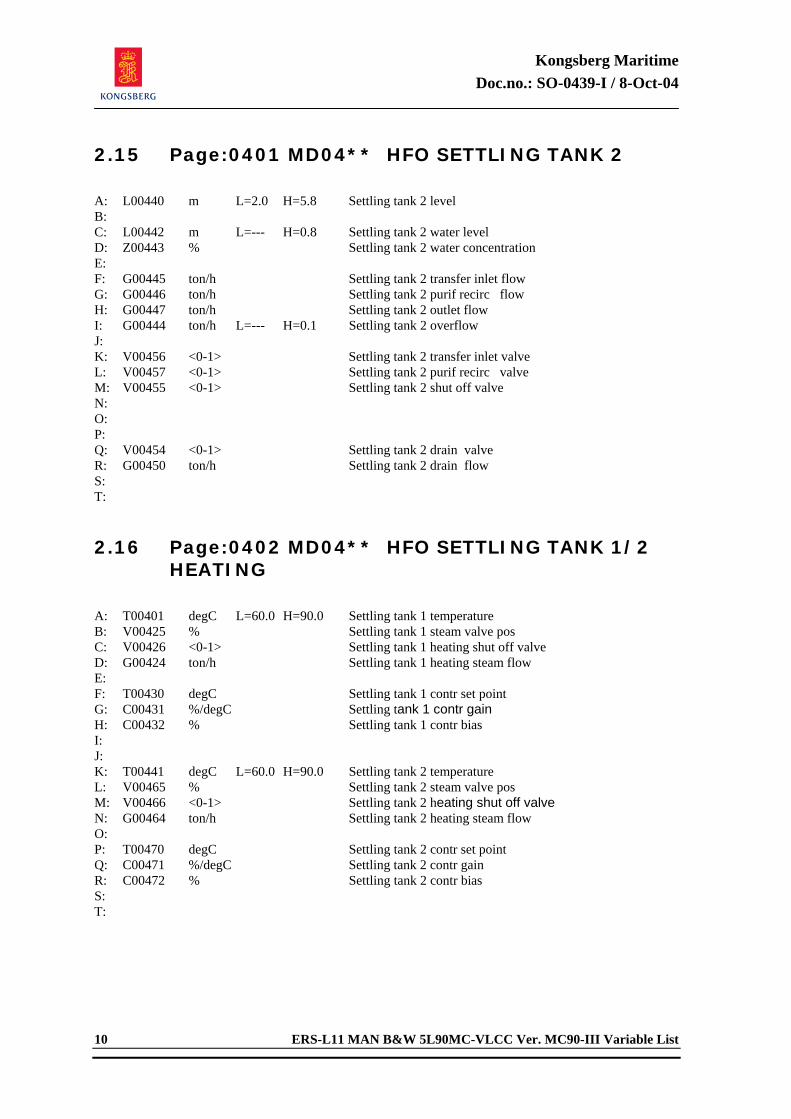
Kongsberg Maritime Doc.no.: SO-0439-I / 8-Oct-04
10 ERS-L11 MAN B&W 5L90MC-VLCC Ver. MC90-III Variable List
2.15 Page:0401 MD04** HFO SETTLING TANK 2
A: L00440 m L=2.0 H=5.8 Settling tank 2 level B: C: L00442 m L=--- H=0.8 Settling tank 2 water level D: Z00443 % Settling tank 2 water concentration E: F: G00445 ton/h Settling tank 2 transfer inlet flow G: G00446 ton/h Settling tank 2 purif recirc flow H: G00447 ton/h Settling tank 2 outlet flow I: G00444 ton/h L=--- H=0.1 Settling tank 2 overflow J: K: V00456 <0-1> Settling tank 2 transfer inlet valve L: V00457 <0-1> Settling tank 2 purif recirc valve M: V00455 <0-1> Settling tank 2 shut off valve N: O: P: Q: V00454 <0-1> Settling tank 2 drain valve R: G00450 ton/h Settling tank 2 drain flow S: T: 2.16 Page:0402 MD04** HFO SETTLING TANK 1/2
HEATING
A: T00401 degC L=60.0 H=90.0 Settling tank 1 temperature B: V00425 % Settling tank 1 steam valve pos C: V00426 <0-1> Settling tank 1 heating shut off valve D: G00424 ton/h Settling tank 1 heating steam flow E: F: T00430 degC Settling tank 1 contr set point G: C00431 %/degC Settling tank 1 contr gain H: C00432 % Settling tank 1 contr bias I: J: K: T00441 degC L=60.0 H=90.0 Settling tank 2 temperature L: V00465 % Settling tank 2 steam valve pos M: V00466 <0-1> Settling tank 2 heating shut off valve N: G00464 ton/h Settling tank 2 heating steam flow O: P: T00470 degC Settling tank 2 contr set point Q: C00471 %/degC Settling tank 2 contr gain R: C00472 % Settling tank 2 contr bias S: T:
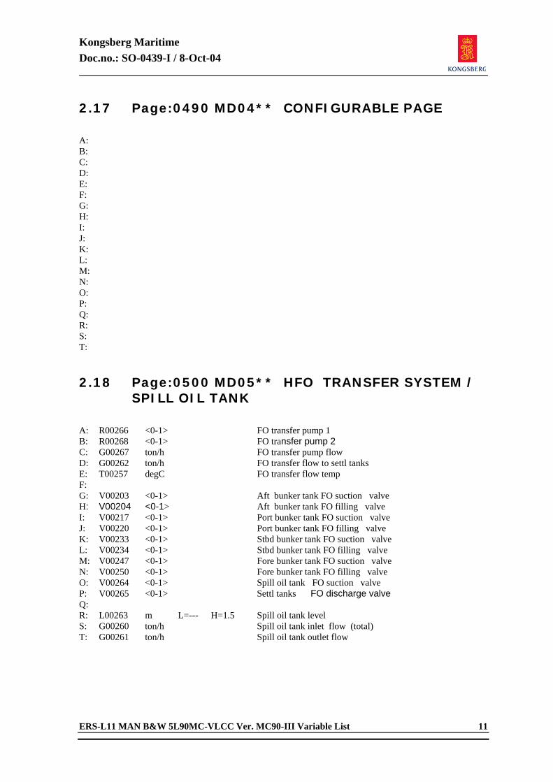
Kongsberg Maritime Doc.no.: SO-0439-I / 8-Oct-04
ERS-L11 MAN B&W 5L90MC-VLCC Ver. MC90-III Variable List 11
2.17 Page:0490 MD04** CONFIGURABLE PAGE
A: B: C: D: E: F: G: H: I: J: K: L: M: N: O: P: Q: R: S: T: 2.18 Page:0500 MD05** HFO TRANSFER SYSTEM /
SPILL OIL TANK
A: R00266 <0-1> FO transfer pump 1 B: R00268 <0-1> FO transfer pump 2 C: G00267 ton/h FO transfer pump flow D: G00262 ton/h FO transfer flow to settl tanks E: T00257 degC FO transfer flow temp F: G: V00203 <0-1> Aft bunker tank FO suction valve H: V00204 <0-1> Aft bunker tank FO filling valve I: V00217 <0-1> Port bunker tank FO suction valve J: V00220 <0-1> Port bunker tank FO filling valve K: V00233 <0-1> Stbd bunker tank FO suction valve L: V00234 <0-1> Stbd bunker tank FO filling valve M: V00247 <0-1> Fore bunker tank FO suction valve N: V00250 <0-1> Fore bunker tank FO filling valve O: V00264 <0-1> Spill oil tank FO suction valve P: V00265 <0-1> Settl tanks FO discharge valve Q: R: L00263 m L=--- H=1.5 Spill oil tank level S: G00260 ton/h Spill oil tank inlet flow (total) T: G00261 ton/h Spill oil tank outlet flow
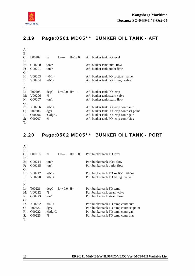
Kongsberg Maritime Doc.no.: SO-0439-I / 8-Oct-04
12 ERS-L11 MAN B&W 5L90MC-VLCC Ver. MC90-III Variable List
2.19 Page:0501 MD05** BUNKER OIL TANK - AFT
A: B: C: L00202 m L=--- H=19.0 Aft bunker tank FO level D: E: G00200 ton/h Aft bunker tank inlet flow F: G00201 ton/h Aft bunker tank outlet flow G: H: V00203 <0-1> Aft bunker tank FO suction valve I: V00204 <0-1> Aft bunker tank FO filling valve J: K: L: T00205 degC L=40.0 H=--- Aft bunker tank FO temp M: V00206 % Aft bunker tank steam valve N: G00207 ton/h Aft bunker tank steam flow O: P: X00206 <0-1> Aft bunker tank FO temp contr auto Q: T00206 dgrC Aft bunker tank FO temp contr set point R: C00206 %/dgrC Aft bunker tank FO temp contr gain S: C00207 % Aft bunker tank FO temp contr bias T: 2.20 Page:0502 MD05** BUNKER OIL TANK - PORT
A: B: C: L00216 m L=--- H=19.0 Port bunker tank FO level D: E: G00214 ton/h Port bunker tank inlet flow F: G00215 ton/h Port bunker tank outlet flow G: H: V00217 <0-1> Port bunker tank FO suction valve I: V00220 <0-1> Port bunker tank FO filling valve J: K: L: T00221 degC L=40.0 H=--- Port bunker tank FO temp M: V00222 % Port bunker tank steam valve N: G00223 ton/h Port bunker tank steam flow O: P: X00222 <0-1> Port bunker tank FO temp contr auto Q: T00222 dgrC Port bunker tank FO temp contr set point R: C00222 %/dgrC Port bunker tank FO temp contr gain S: C00223 % Port bunker tank FO temp contr bias T:
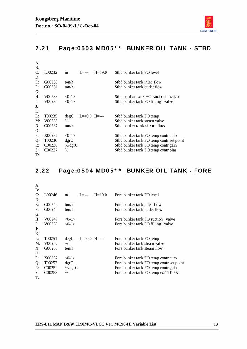
Kongsberg Maritime Doc.no.: SO-0439-I / 8-Oct-04
ERS-L11 MAN B&W 5L90MC-VLCC Ver. MC90-III Variable List 13
2.21 Page:0503 MD05** BUNKER OIL TANK - STBD
A: B: C: L00232 m L=--- H=19.0 Stbd bunker tank FO level D: E: G00230 ton/h Stbd bunker tank inlet flow F: G00231 ton/h Stbd bunker tank outlet flow G: H: V00233 <0-1> Stbd bunker tank FO suction valve I: V00234 <0-1> Stbd bunker tank FO filling valve J: K: L: T00235 degC L=40.0 H=--- Stbd bunker tank FO temp M: V00236 % Stbd bunker tank steam valve N: G00237 ton/h Stbd bunker tank steam flow O: P: X00236 <0-1> Stbd bunker tank FO temp contr auto Q: T00236 dgrC Stbd bunker tank FO temp contr set point R: C00236 %/dgrC Stbd bunker tank FO temp contr gain S: C00237 % Stbd bunker tank FO temp contr bias T: 2.22 Page:0504 MD05** BUNKER OIL TANK - FORE
A: B: C: L00246 m L=--- H=19.0 Fore bunker tank FO level D: E: G00244 ton/h Fore bunker tank inlet flow F: G00245 ton/h Fore bunker tank outlet flow G: H: V00247 <0-1> Fore bunker tank FO suction valve I: V00250 <0-1> Fore bunker tank FO filling valve J: K: L: T00251 degC L=40.0 H=--- Fore bunker tank FO temp M: V00252 % Fore bunker tank steam valve N: G00253 ton/h Fore bunker tank steam flow O: P: X00252 <0-1> Fore bunker tank FO temp contr auto Q: T00252 dgrC Fore bunker tank FO temp contr set point R: C00252 %/dgrC Fore bunker tank FO temp contr gain S: C00253 % Fore bunker tank FO temp contr bias T:
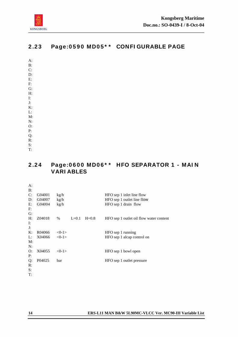
Kongsberg Maritime Doc.no.: SO-0439-I / 8-Oct-04
14 ERS-L11 MAN B&W 5L90MC-VLCC Ver. MC90-III Variable List
2.23 Page:0590 MD05** CONFIGURABLE PAGE
A: B: C: D: E: F: G: H: I: J: K: L: M: N: O: P: Q: R: S: T: 2.24 Page:0600 MD06** HFO SEPARATOR 1 - MAIN
VARIABLES
A: B: C: G04001 kg/h HFO sep 1 inlet line flow D: G04007 kg/h HFO sep 1 outlet line flow E: G04004 kg/h HFO sep 1 drain flow F: G: H: Z04018 % L=0.1 H=0.8 HFO sep 1 outlet oil flow water content I: J: K: R04066 <0-1> HFO sep 1 running L: X04066 <0-1> HFO sep 1 alcap control on M: N: O: X04055 <0-1> HFO sep 1 bowl open P: Q: P04025 bar HFO sep 1 outlet pressure R: S: T:
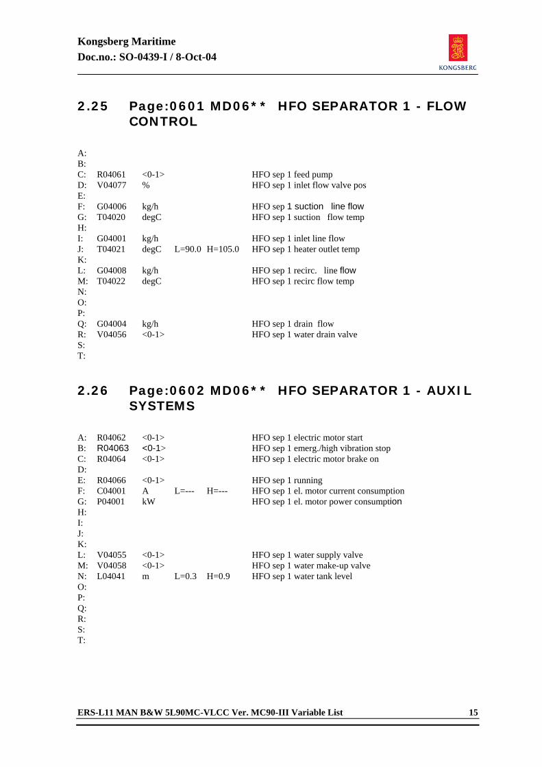
Kongsberg Maritime Doc.no.: SO-0439-I / 8-Oct-04
ERS-L11 MAN B&W 5L90MC-VLCC Ver. MC90-III Variable List 15
2.25 Page:0601 MD06** HFO SEPARATOR 1 - FLOW CONTROL
A: B: C: R04061 <0-1> HFO sep 1 feed pump D: V04077 % HFO sep 1 inlet flow valve pos E: F: G04006 kg/h HFO sep 1 suction line flow G: T04020 degC HFO sep 1 suction flow temp H: I: G04001 kg/h HFO sep 1 inlet line flow J: T04021 degC L=90.0 H=105.0 HFO sep 1 heater outlet temp K: L: G04008 kg/h HFO sep 1 recirc. line flow M: T04022 degC HFO sep 1 recirc flow temp N: O: P: Q: G04004 kg/h HFO sep 1 drain flow R: V04056 <0-1> HFO sep 1 water drain valve S: T: 2.26 Page:0602 MD06** HFO SEPARATOR 1 - AUXIL
SYSTEMS
A: R04062 <0-1> HFO sep 1 electric motor start B: R04063 <0-1> HFO sep 1 emerg./high vibration stop C: R04064 <0-1> HFO sep 1 electric motor brake on D: E: R04066 <0-1> HFO sep 1 running F: C04001 A L=--- H=--- HFO sep 1 el. motor current consumption G: P04001 kW HFO sep 1 el. motor power consumption H: I: J: K: L: V04055 <0-1> HFO sep 1 water supply valve M: V04058 <0-1> HFO sep 1 water make-up valve N: L04041 m L=0.3 H=0.9 HFO sep 1 water tank level O: P: Q: R: S: T:
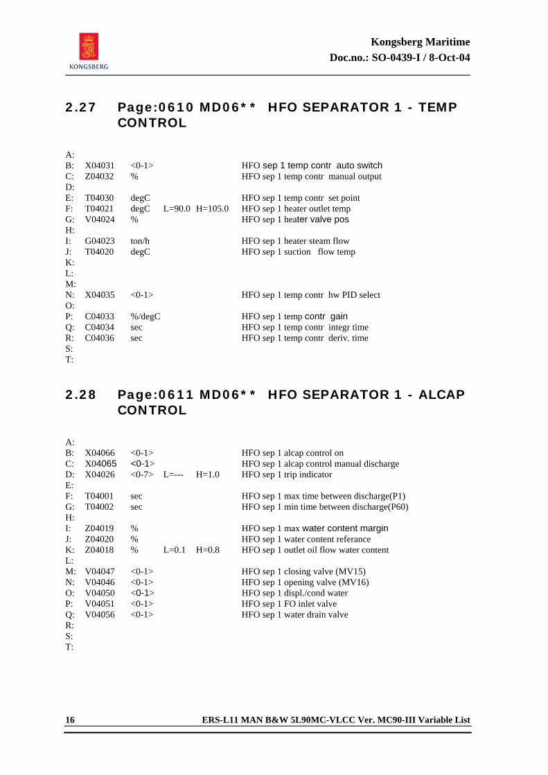
Kongsberg Maritime Doc.no.: SO-0439-I / 8-Oct-04
16 ERS-L11 MAN B&W 5L90MC-VLCC Ver. MC90-III Variable List
2.27 Page:0610 MD06** HFO SEPARATOR 1 - TEMP CONTROL
A: B: X04031 <0-1> HFO sep 1 temp contr auto switch C: Z04032 % HFO sep 1 temp contr manual output D: E: T04030 degC HFO sep 1 temp contr set point F: T04021 degC L=90.0 H=105.0 HFO sep 1 heater outlet temp G: V04024 % HFO sep 1 heater valve pos H: I: G04023 ton/h HFO sep 1 heater steam flow J: T04020 degC HFO sep 1 suction flow temp K: L: M: N: X04035 <0-1> HFO sep 1 temp contr hw PID select O: P: C04033 %/degC HFO sep 1 temp contr gain Q: C04034 sec HFO sep 1 temp contr integr time R: C04036 sec HFO sep 1 temp contr deriv. time S: T: 2.28 Page:0611 MD06** HFO SEPARATOR 1 - ALCAP
CONTROL
A: B: X04066 <0-1> HFO sep 1 alcap control on C: X04065 <0-1> HFO sep 1 alcap control manual discharge D: X04026 <0-7> L=--- H=1.0 HFO sep 1 trip indicator E: F: T04001 sec HFO sep 1 max time between discharge(P1) G: T04002 sec HFO sep 1 min time between discharge(P60) H: I: Z04019 % HFO sep 1 max water content margin J: Z04020 % HFO sep 1 water content referance K: Z04018 % L=0.1 H=0.8 HFO sep 1 outlet oil flow water content L: M: V04047 <0-1> HFO sep 1 closing valve (MV15) N: V04046 <0-1> HFO sep 1 opening valve (MV16) O: V04050 <0-1> HFO sep 1 displ./cond water P: V04051 <0-1> HFO sep 1 FO inlet valve Q: V04056 <0-1> HFO sep 1 water drain valve R: S: T:
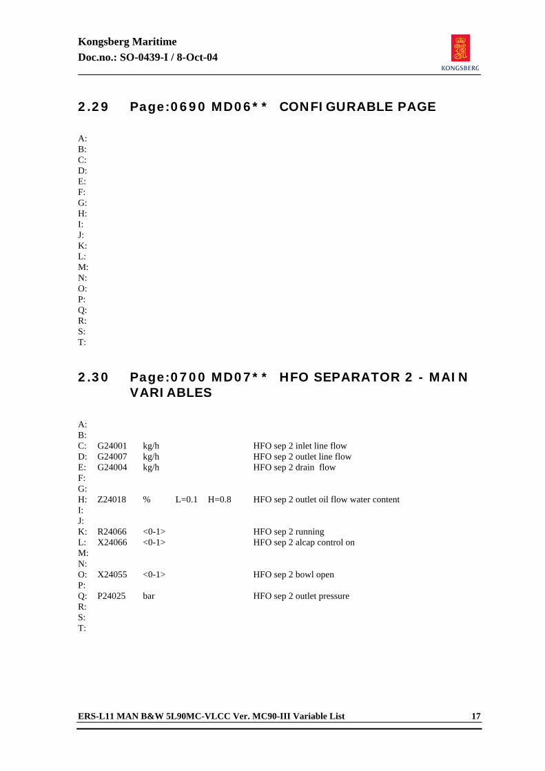
Kongsberg Maritime Doc.no.: SO-0439-I / 8-Oct-04
ERS-L11 MAN B&W 5L90MC-VLCC Ver. MC90-III Variable List 17
2.29 Page:0690 MD06** CONFIGURABLE PAGE
A: B: C: D: E: F: G: H: I: J: K: L: M: N: O: P: Q: R: S: T: 2.30 Page:0700 MD07** HFO SEPARATOR 2 - MAIN
VARIABLES
A: B: C: G24001 kg/h HFO sep 2 inlet line flow D: G24007 kg/h HFO sep 2 outlet line flow E: G24004 kg/h HFO sep 2 drain flow F: G: H: Z24018 % L=0.1 H=0.8 HFO sep 2 outlet oil flow water content I: J: K: R24066 <0-1> HFO sep 2 running L: X24066 <0-1> HFO sep 2 alcap control on M: N: O: X24055 <0-1> HFO sep 2 bowl open P: Q: P24025 bar HFO sep 2 outlet pressure R: S: T:
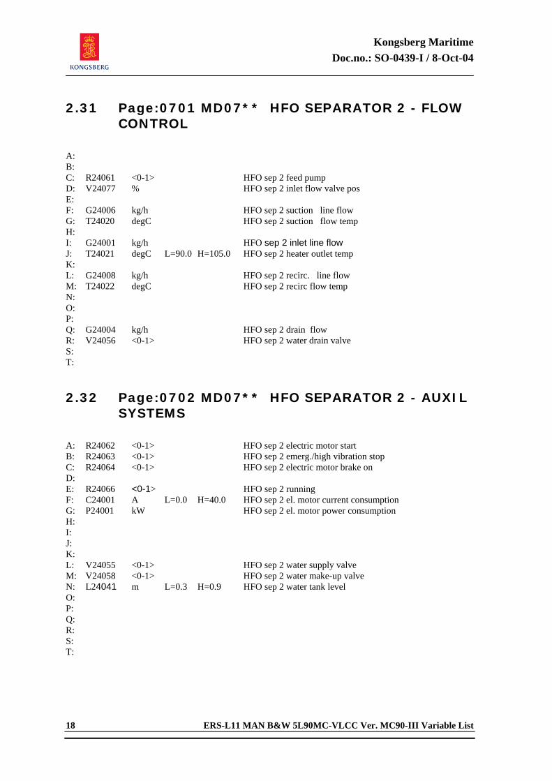
Kongsberg Maritime Doc.no.: SO-0439-I / 8-Oct-04
18 ERS-L11 MAN B&W 5L90MC-VLCC Ver. MC90-III Variable List
2.31 Page:0701 MD07** HFO SEPARATOR 2 - FLOW CONTROL
A: B: C: R24061 <0-1> HFO sep 2 feed pump D: V24077 % HFO sep 2 inlet flow valve pos E: F: G24006 kg/h HFO sep 2 suction line flow G: T24020 degC HFO sep 2 suction flow temp H: I: G24001 kg/h HFO sep 2 inlet line flow J: T24021 degC L=90.0 H=105.0 HFO sep 2 heater outlet temp K: L: G24008 kg/h HFO sep 2 recirc. line flow M: T24022 degC HFO sep 2 recirc flow temp N: O: P: Q: G24004 kg/h HFO sep 2 drain flow R: V24056 <0-1> HFO sep 2 water drain valve S: T: 2.32 Page:0702 MD07** HFO SEPARATOR 2 - AUXIL
SYSTEMS
A: R24062 <0-1> HFO sep 2 electric motor start B: R24063 <0-1> HFO sep 2 emerg./high vibration stop C: R24064 <0-1> HFO sep 2 electric motor brake on D: E: R24066 <0-1> HFO sep 2 running F: C24001 A L=0.0 H=40.0 HFO sep 2 el. motor current consumption G: P24001 kW HFO sep 2 el. motor power consumption H: I: J: K: L: V24055 <0-1> HFO sep 2 water supply valve M: V24058 <0-1> HFO sep 2 water make-up valve N: L24041 m L=0.3 H=0.9 HFO sep 2 water tank level O: P: Q: R: S: T:
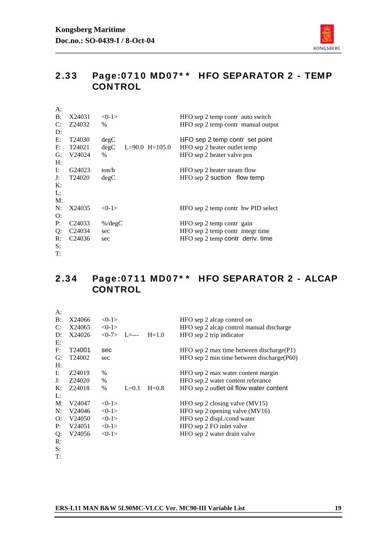
Kongsberg Maritime Doc.no.: SO-0439-I / 8-Oct-04
ERS-L11 MAN B&W 5L90MC-VLCC Ver. MC90-III Variable List 19
2.33 Page:0710 MD07** HFO SEPARATOR 2 - TEMP CONTROL
A: B: X24031 <0-1> HFO sep 2 temp contr auto switch C: Z24032 % HFO sep 2 temp contr manual output D: E: T24030 degC HFO sep 2 temp contr set point F: T24021 degC L=90.0 H=105.0 HFO sep 2 heater outlet temp G: V24024 % HFO sep 2 heater valve pos H: I: G24023 ton/h HFO sep 2 heater steam flow J: T24020 degC HFO sep 2 suction flow temp K: L: M: N: X24035 <0-1> HFO sep 2 temp contr hw PID select O: P: C24033 %/degC HFO sep 2 temp contr gain Q: C24034 sec HFO sep 2 temp contr integr time R: C24036 sec HFO sep 2 temp contr deriv. time S: T: 2.34 Page:0711 MD07** HFO SEPARATOR 2 - ALCAP
CONTROL
A: B: X24066 <0-1> HFO sep 2 alcap control on C: X24065 <0-1> HFO sep 2 alcap control manual discharge D: X24026 <0-7> L=--- H=1.0 HFO sep 2 trip indicator E: F: T24001 sec HFO sep 2 max time between discharge(P1) G: T24002 sec HFO sep 2 min time between discharge(P60) H: I: Z24019 % HFO sep 2 max water content margin J: Z24020 % HFO sep 2 water content referance K: Z24018 % L=0.1 H=0.8 HFO sep 2 outlet oil flow water content L: M: V24047 <0-1> HFO sep 2 closing valve (MV15) N: V24046 <0-1> HFO sep 2 opening valve (MV16) O: V24050 <0-1> HFO sep 2 displ./cond water P: V24051 <0-1> HFO sep 2 FO inlet valve Q: V24056 <0-1> HFO sep 2 water drain valve R: S: T:
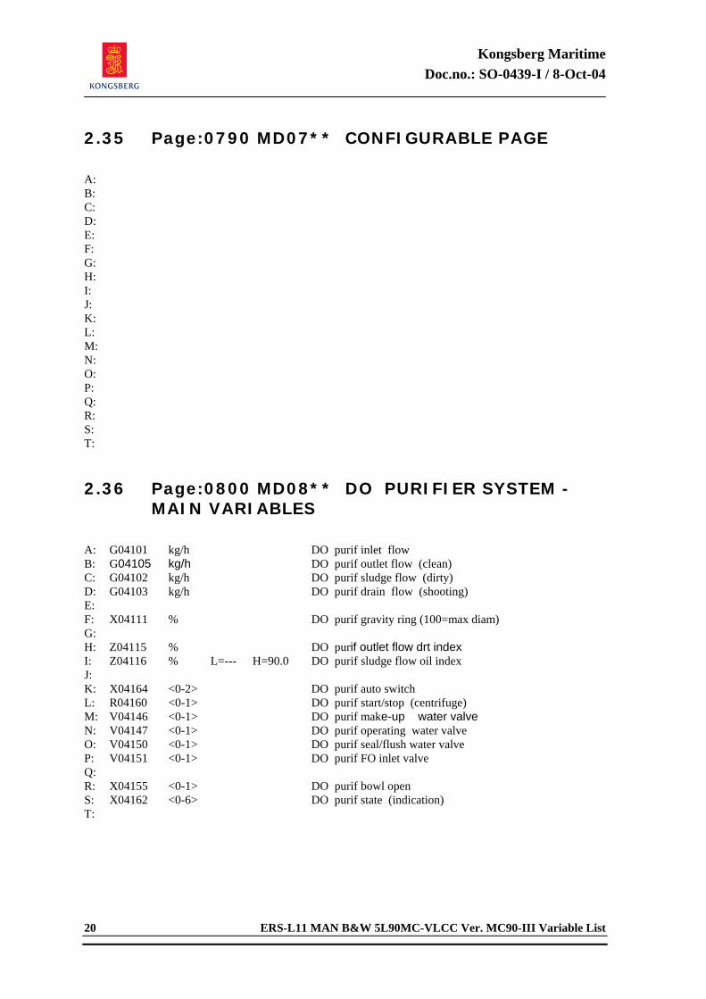
Kongsberg Maritime Doc.no.: SO-0439-I / 8-Oct-04
20 ERS-L11 MAN B&W 5L90MC-VLCC Ver. MC90-III Variable List
2.35 Page:0790 MD07** CONFIGURABLE PAGE
A: B: C: D: E: F: G: H: I: J: K: L: M: N: O: P: Q: R: S: T: 2.36 Page:0800 MD08** DO PURIFIER SYSTEM -
MAIN VARIABLES
A: G04101 kg/h DO purif inlet flow B: G04105 kg/h DO purif outlet flow (clean) C: G04102 kg/h DO purif sludge flow (dirty) D: G04103 kg/h DO purif drain flow (shooting) E: F: X04111 % DO purif gravity ring (100=max diam) G: H: Z04115 % DO purif outlet flow drt index I: Z04116 % L=--- H=90.0 DO purif sludge flow oil index J: K: X04164 <0-2> DO purif auto switch L: R04160 <0-1> DO purif start/stop (centrifuge) M: V04146 <0-1> DO purif make-up water valve N: V04147 <0-1> DO purif operating water valve O: V04150 <0-1> DO purif seal/flush water valve P: V04151 <0-1> DO purif FO inlet valve Q: R: X04155 <0-1> DO purif bowl open S: X04162 <0-6> DO purif state (indication) T:
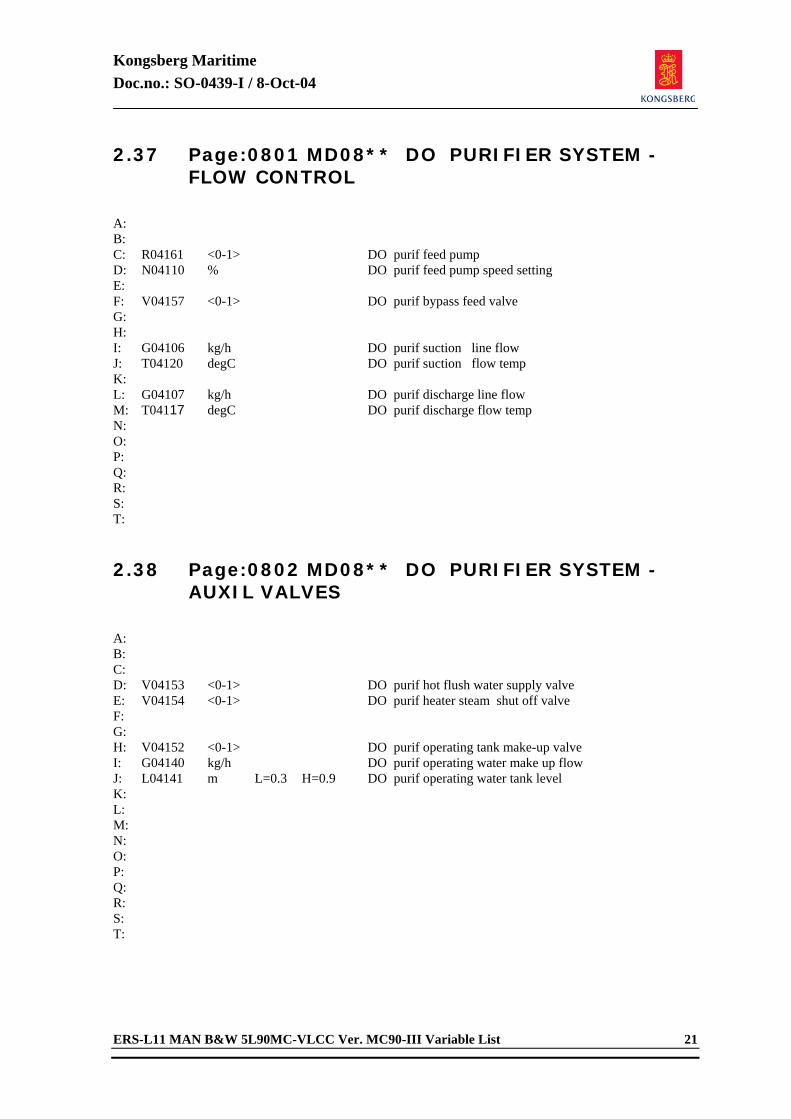
Kongsberg Maritime Doc.no.: SO-0439-I / 8-Oct-04
ERS-L11 MAN B&W 5L90MC-VLCC Ver. MC90-III Variable List 21
2.37 Page:0801 MD08** DO PURIFIER SYSTEM - FLOW CONTROL
A: B: C: R04161 <0-1> DO purif feed pump D: N04110 % DO purif feed pump speed setting E: F: V04157 <0-1> DO purif bypass feed valve G: H: I: G04106 kg/h DO purif suction line flow J: T04120 degC DO purif suction flow temp K: L: G04107 kg/h DO purif discharge line flow M: T04117 degC DO purif discharge flow temp N: O: P: Q: R: S: T: 2.38 Page:0802 MD08** DO PURIFIER SYSTEM -
AUXIL VALVES
A: B: C: D: V04153 <0-1> DO purif hot flush water supply valve E: V04154 <0-1> DO purif heater steam shut off valve F: G: H: V04152 <0-1> DO purif operating tank make-up valve I: G04140 kg/h DO purif operating water make up flow J: L04141 m L=0.3 H=0.9 DO purif operating water tank level K: L: M: N: O: P: Q: R: S: T:
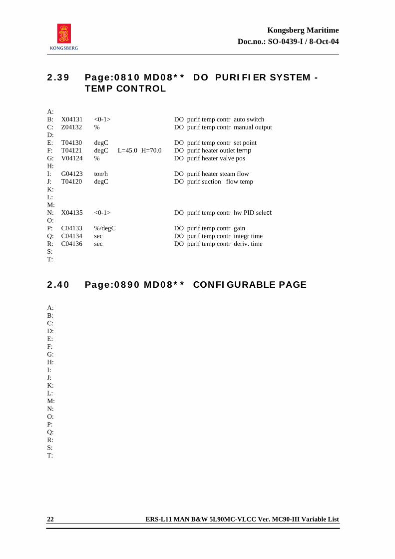
Kongsberg Maritime Doc.no.: SO-0439-I / 8-Oct-04
22 ERS-L11 MAN B&W 5L90MC-VLCC Ver. MC90-III Variable List
2.39 Page:0810 MD08** DO PURIFIER SYSTEM - TEMP CONTROL
A: B: X04131 <0-1> DO purif temp contr auto switch C: Z04132 % DO purif temp contr manual output D: E: T04130 degC DO purif temp contr set point F: T04121 degC L=45.0 H=70.0 DO purif heater outlet temp G: V04124 % DO purif heater valve pos H: I: G04123 ton/h DO purif heater steam flow J: T04120 degC DO purif suction flow temp K: L: M: N: X04135 <0-1> DO purif temp contr hw PID select O: P: C04133 %/degC DO purif temp contr gain Q: C04134 sec DO purif temp contr integr time R: C04136 sec DO purif temp contr deriv. time S: T: 2.40 Page:0890 MD08** CONFIGURABLE PAGE
A: B: C: D: E: F: G: H: I: J: K: L: M: N: O: P: Q: R: S: T:
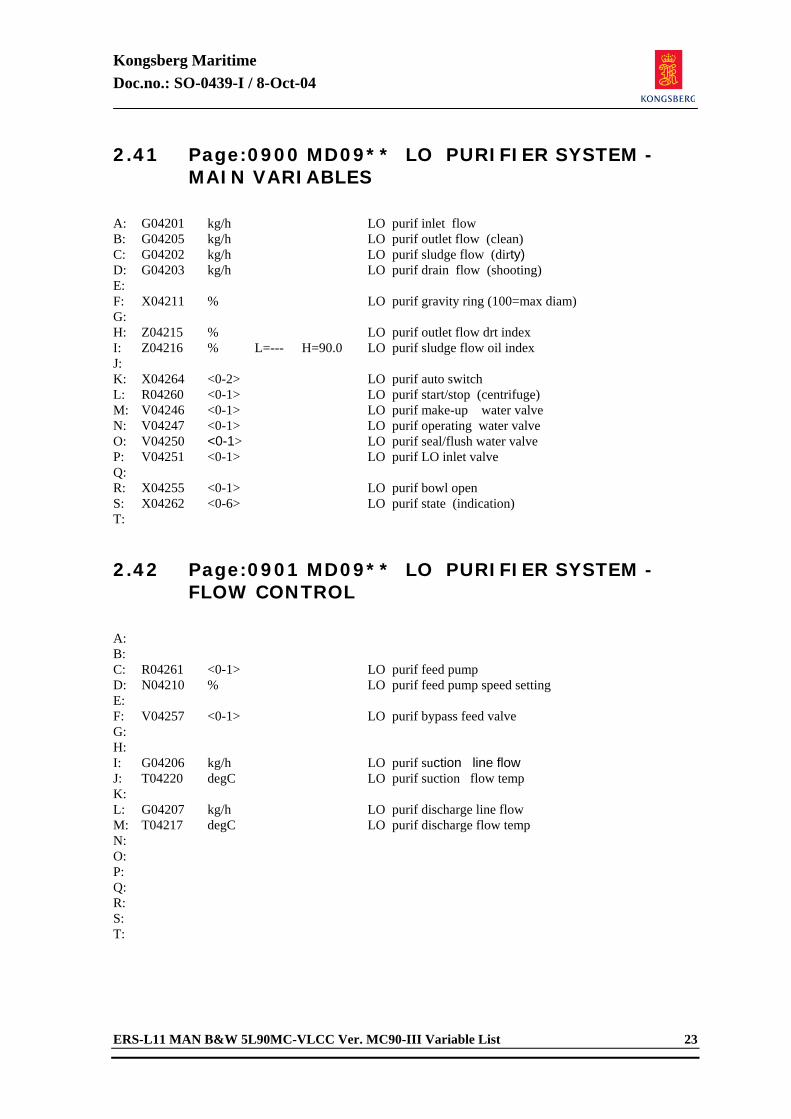
Kongsberg Maritime Doc.no.: SO-0439-I / 8-Oct-04
ERS-L11 MAN B&W 5L90MC-VLCC Ver. MC90-III Variable List 23
2.41 Page:0900 MD09** LO PURIFIER SYSTEM - MAIN VARIABLES
A: G04201 kg/h LO purif inlet flow B: G04205 kg/h LO purif outlet flow (clean) C: G04202 kg/h LO purif sludge flow (dirty) D: G04203 kg/h LO purif drain flow (shooting) E: F: X04211 % LO purif gravity ring (100=max diam) G: H: Z04215 % LO purif outlet flow drt index I: Z04216 % L=--- H=90.0 LO purif sludge flow oil index J: K: X04264 <0-2> LO purif auto switch L: R04260 <0-1> LO purif start/stop (centrifuge) M: V04246 <0-1> LO purif make-up water valve N: V04247 <0-1> LO purif operating water valve O: V04250 <0-1> LO purif seal/flush water valve P: V04251 <0-1> LO purif LO inlet valve Q: R: X04255 <0-1> LO purif bowl open S: X04262 <0-6> LO purif state (indication) T: 2.42 Page:0901 MD09** LO PURIFIER SYSTEM -
FLOW CONTROL
A: B: C: R04261 <0-1> LO purif feed pump D: N04210 % LO purif feed pump speed setting E: F: V04257 <0-1> LO purif bypass feed valve G: H: I: G04206 kg/h LO purif suction line flow J: T04220 degC LO purif suction flow temp K: L: G04207 kg/h LO purif discharge line flow M: T04217 degC LO purif discharge flow temp N: O: P: Q: R: S: T:
Kongsberg Maritime Doc.no.: SO-0439-I / 8-Oct-04
24 ERS-L11 MAN B&W 5L90MC-VLCC Ver. MC90-III Variable List
2.43 Page:0902 MD09** LO PURIFIER SYSTEM - AUXIL VALVES
A: B: C: D: V04253 <0-1> LO purif hot flush water supply valve E: V04254 <0-1> LO purif heater steam shut off valve F: G: H: V04252 <0-1> LO purif operating tank make-up valve I: G04240 kg/h LO purif operating water make up flow J: L04241 m L=0.3 H=0.9 LO purif operating water tank level K: L: M: N: O: P: Q: R: S: T: 2.44 Page:0910 MD09** LO PURIFIER SYSTEM -
TEMP CONTROL
A: B: X04231 <0-1> LO purif temp contr auto switch C: Z04232 % LO purif temp contr manual output D: E: T04230 degC LO purif temp contr set point F: T04221 degC L=80.0 H=95.0 LO purif heater outlet temp G: V04224 % LO purif heater valve pos H: I: G04223 ton/h LO purif heater steam flow J: T04220 degC LO purif suction flow temp K: L: M: N: X04235 <0-1> LO purif temp contr hw PID select O: P: C04233 %/degC LO purif temp contr gain Q: C04234 sec LO purif temp contr integr time R: C04236 sec LO purif temp contr deriv. time S: T:
Kongsberg Maritime Doc.no.: SO-0439-I / 8-Oct-04
ERS-L11 MAN B&W 5L90MC-VLCC Ver. MC90-III Variable List 25
2.45 Page:0990 MD09** CONFIGURABLE PAGE
A: B: C: D: E: F: G: H: I: J: K: L: M: N: O: P: Q: R: S: T: 2.46 Page:1000 MD10** ME FW SYSTEM - MAIN
VARIABLES
A: B: P01000 bar LTFW pump suction pressure C: P01001 bar L=2.2 H=--- LTFW pump discharge pressure D: P01002 bar LTFW / HTFW junction pressure E: F: P01003 bar HTFW pump suction pressure G: P01004 bar HTFW pump discharge pressure H: P01005 bar L=1.4 H=--- HTFW press inlet ME I: P01006 bar FW press inlet FWC 1/2 J: K: T01013 degC LTFW temp outlet FWC 1 L: T01014 degC LTFW temp outlet FWC 2 M: T01015 degC L=26.0 H=36.0 LTFW temp outlet LTFW pumps N: T01016 degC LTFW temp at LT/HT junction O: P: T01017 degC HTFW temp outlet HTFW pumps Q: T01010 degC L=60.0 H=--- HTFW temp inlet ME R: T01011 degC L=--- H=88.0 HTFW temp outlet ME S: T01012 degC FW temp inlet FWC 1/2 T:
Kongsberg Maritime Doc.no.: SO-0439-I / 8-Oct-04
26 ERS-L11 MAN B&W 5L90MC-VLCC Ver. MC90-III Variable List
2.47 Page:1001 MD10** ME FW SYSTEM - AUXIL VARIABLES
A: B: T01030 degC LTFW temp outlet ME airc 1 C: T01031 degC LTFW temp outlet ME airc 2 D: E: T01032 degC LTFW temp outlet ME oilc 1 F: T01033 degC LTFW temp outlet ME oilc 2 G: T01034 degC LTFW temp outlet ME cam LOC H: I: T01035 degC LTFW temp outlet air compr J: T01036 degC LTFW temp outlet TG / CT K: T01037 degC LTFW temp outlet servo / sternt L: T01038 degC LTFW temp outlet TO cooler M: N: T01020 degC HTFW temp outlet fresh w gen O: T01021 degC HTFW temp inlet ME preheater P: T01022 degC HTFW temp outlet ME preheater Q: R: S: T: 2.48 Page:1002 MD10** ME FW SYSTEM - HTFW
FLOWS
A: B: C: G01050 ton/h HTFW flow inlet ME D: G01051 ton/h HTFW flow inlet recirc valve E: G01052 ton/h LTFW flow inlet recirc valve F: G: G01054 ton/h HTFW flow to FWC 1/2 H: G01055 ton/h LTFW flow to FWC 1/2 I: J: G01056 ton/h LTFW flow inlet FWC 1 K: G01057 ton/h LTFW flow inlet FWC 2 L: G01060 ton/h LTFW flow bypass FWC 1/2 M: N: O: G01023 ton/h HTFW flow inlet fresh w gen P: G01024 ton/h HTFW flow inlet ME preheater Q: R: S: T:
Kongsberg Maritime Doc.no.: SO-0439-I / 8-Oct-04
ERS-L11 MAN B&W 5L90MC-VLCC Ver. MC90-III Variable List 27
2.49 Page:1003 MD10** ME FW SYSTEM - HTFW VALVES / PUMPS
A: R01110 <0-1> Main HTFW pump 1 B: R01111 <0-1> Main HTFW pump 2 C: R01112 <0-1> Auxil HTFW pump D: V01161 <0-1> HTFW inlet ME shut off valve E: V01162 <0-1> HTFW outlet ME shut off valve F: G: V06733 <0-1> Fresh w gen FW inlet shut off valve H: V06734 <0-1> Fresh w gen FW outlet shut off valve I: V06735 % Fresh w gen FW bypass valve J: K: L: V01140 <0-1> HTFW ME preheater inlet valve M: V01141 <0-1> HTFW ME preheater bypass valve N: V01142 <0-1> HTFW ME preheater steam valve O: G01143 ton/h HTFW ME preheater steam flow P: Q: V01163 <0-1> HTFW drain valve R: V01164 <0-1> HTFW vent valve S: T: V01113 <0-1> HTFW recirc bypass valve 2.50 Page:1004 MD10** ME FW SYSTEM - LTFW
FLOWS
A: B: C: G01061 ton/h LTFW pump flow (total) D: E: G01070 ton/h LTFW flow inlet ME airc 1 F: G01071 ton/h LTFW flow inlet ME airc 2 G: H: G01072 ton/h LTFW flow inlet ME LOC 1 I: G01073 ton/h LTFW flow inlet ME LOC 2 J: G01074 ton/h LTFW flow inlet ME cam LOC K: L: G01075 ton/h LTFW flow to air compr M: G01076 ton/h LTFW flow to TG / CT N: G01077 ton/h LTFW flow to servo / sternt O: G01078 ton/h LTFW flow to TO cooler P: Q: R: S: T:
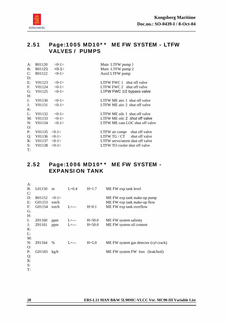
Kongsberg Maritime Doc.no.: SO-0439-I / 8-Oct-04
28 ERS-L11 MAN B&W 5L90MC-VLCC Ver. MC90-III Variable List
2.51 Page:1005 MD10** ME FW SYSTEM - LTFW VALVES / PUMPS
A: R01120 <0-1> Main LTFW pump 1 B: R01121 <0-1> Main LTFW pump 2 C: R01122 <0-1> Auxil LTFW pump D: E: V01123 <0-1> LTFW FWC 1 shut off valve F: V01124 <0-1> LTFW FWC 2 shut off valve G: V01125 <0-1> LTFW FWC 1/2 bypass valve H: I: V01130 <0-1> LTFW ME airc 1 shut off valve J: V01131 <0-1> LTFW ME airc 2 shut off valve K: L: V01132 <0-1> LTFW ME oilc 1 shut off valve M: V01133 <0-1> LTFW ME oilc 2 shut off valve N: V01134 <0-1> LTFW ME cam LOC shut off valve O: P: V01135 <0-1> LTFW air compr shut off valve Q: V01136 <0-1> LTFW TG / CT shut off valve R: V01137 <0-1> LTFW servo/sternt shut off valve S: V01138 <0-1> LTFW TO cooler shut off valve T: 2.52 Page:1006 MD10** ME FW SYSTEM -
EXPANSION TANK
A: B: L01150 m L=0.4 H=1.7 ME FW exp tank level C: D: R01152 <0-1> ME FW exp tank make-up pump E: G01153 ton/h ME FW exp tank make-up flow F: G01154 ton/h L=--- H=0.1 ME FW exp tank overflow G: H: I: Z01160 ppm L=--- H=50.0 ME FW system salinity J: Z01161 ppm L=--- H=50.0 ME FW system oil content K: L: M: N: Z01164 % L=--- H=5.0 ME FW system gas detector (cyl crack) O: P: G01165 kg/h ME FW system FW loss (leak/boil) Q: R: S: T:
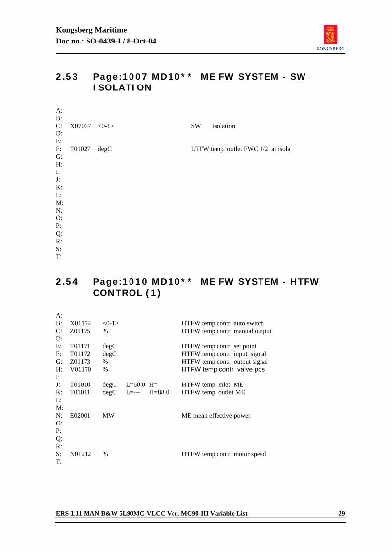
Kongsberg Maritime Doc.no.: SO-0439-I / 8-Oct-04
ERS-L11 MAN B&W 5L90MC-VLCC Ver. MC90-III Variable List 29
2.53 Page:1007 MD10** ME FW SYSTEM - SW ISOLATION
A: B: C: X07037 <0-1> SW isolation D: E: F: T01027 degC LTFW temp outlet FWC 1/2 at isola G: H: I: J: K: L: M: N: O: P: Q: R: S: T: 2.54 Page:1010 MD10** ME FW SYSTEM - HTFW
CONTROL (1)
A: B: X01174 <0-1> HTFW temp contr auto switch C: Z01175 % HTFW temp contr manual output D: E: T01171 degC HTFW temp contr set point F: T01172 degC HTFW temp contr input signal G: Z01173 % HTFW temp contr output signal H: V01170 % HTFW temp contr valve pos I: J: T01010 degC L=60.0 H=--- HTFW temp inlet ME K: T01011 degC L=--- H=88.0 HTFW temp outlet ME L: M: N: E02001 MW ME mean effective power O: P: Q: R: S: N01212 % HTFW temp contr motor speed T:
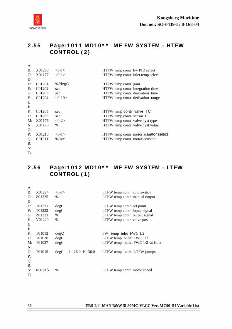
Kongsberg Maritime Doc.no.: SO-0439-I / 8-Oct-04
30 ERS-L11 MAN B&W 5L90MC-VLCC Ver. MC90-III Variable List
2.55 Page:1011 MD10** ME FW SYSTEM - HTFW CONTROL (2)
A: B: X01200 <0-1> HTFW temp contr hw PID select C: X01177 <0-1> HTFW temp contr inlet temp select D: E: C01201 %/degC HTFW temp contr gain F: C01202 sec HTFW temp contr integration time G: C01203 sec HTFW temp contr derivation time H: C01204 <0-10> HTFW temp contr derivation range I: J: K: C01205 sec HTFW temp contr valve TC L: C01206 sec HTFW temp contr sensor TC M: X01176 <0-2> HTFW temp contr valve hyst type N: X01178 % HTFW temp contr valve hyst value O: P: X01210 <0-1> HTFW temp contr motor actuator select Q: C01211 %/sec HTFW temp contr motor constant R: S: T: 2.56 Page:1012 MD10** ME FW SYSTEM - LTFW
CONTROL (1)
A: B: X01224 <0-1> LTFW temp contr auto switch C: Z01225 % LTFW temp contr manual output D: E: T01221 degC LTFW temp contr set point F: T01222 degC LTFW temp contr input signal G: Z01223 % LTFW temp contr output signal H: V01220 % LTFW temp contr valve pos I: J: K: T01012 degC FW temp inlet FWC 1/2 L: T01026 degC LTFW temp outlet FWC 1/2 M: T01027 degC LTFW temp outlet FWC 1/2 at isola N: O: T01015 degC L=26.0 H=36.0 LTFW temp outlet LTFW pumps P: Q: R: S: N01216 % LTFW temp contr motor speed T:
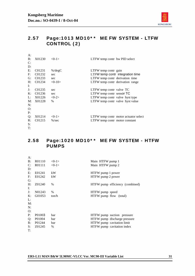
Kongsberg Maritime Doc.no.: SO-0439-I / 8-Oct-04
ERS-L11 MAN B&W 5L90MC-VLCC Ver. MC90-III Variable List 31
2.57 Page:1013 MD10** ME FW SYSTEM - LTFW CONTROL (2)
A: B: X01230 <0-1> LTFW temp contr hw PID select C: D: E: C01231 %/degC LTFW temp contr gain F: C01232 sec LTFW temp contr integration time G: C01233 sec LTFW temp contr derivation time H: C01234 <0-10> LTFW temp contr derivation range I: J: C01235 sec LTFW temp contr valve TC K: C01236 sec LTFW temp contr sensor TC L: X01226 <0-2> LTFW temp contr valve hyst type M: X01228 % LTFW temp contr valve hyst value N: O: P: Q: X01214 <0-1> LTFW temp contr motor actuator select R: C01215 %/sec LTFW temp contr motor constant S: T: 2.58 Page:1020 MD10** ME FW SYSTEM - HTFW
PUMPS
A: B: R01110 <0-1> Main HTFW pump 1 C: R01111 <0-1> Main HTFW pump 2 D: E: E01241 kW HTFW pump 1 power F: E01242 kW HTFW pump 2 power G: H: Z01240 % HTFW pump efficiency (combined) I: J: N01243 % HTFW pump speed K: G01053 ton/h HTFW pump flow (total) L: M: N: O: P: P01003 bar HTFW pump suction pressure Q: P01004 bar HTFW pump discharge pressure R: P01244 bar HTFW pump cavitation limit S: Z01245 % HTFW pump cavitation index T:
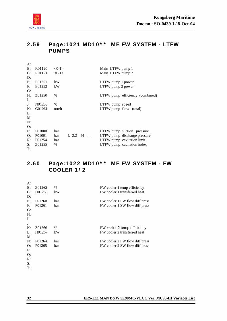
Kongsberg Maritime Doc.no.: SO-0439-I / 8-Oct-04
32 ERS-L11 MAN B&W 5L90MC-VLCC Ver. MC90-III Variable List
2.59 Page:1021 MD10** ME FW SYSTEM - LTFW PUMPS
A: B: R01120 <0-1> Main LTFW pump 1 C: R01121 <0-1> Main LTFW pump 2 D: E: E01251 kW LTFW pump 1 power F: E01252 kW LTFW pump 2 power G: H: Z01250 % LTFW pump efficiency (combined) I: J: N01253 % LTFW pump speed K: G01061 ton/h LTFW pump flow (total) L: M: N: O: P: P01000 bar LTFW pump suction pressure Q: P01001 bar L=2.2 H=--- LTFW pump discharge pressure R: P01254 bar LTFW pump cavitation limit S: Z01255 % LTFW pump cavitation index T: 2.60 Page:1022 MD10** ME FW SYSTEM - FW
COOLER 1/2
A: B: Z01262 % FW cooler 1 temp efficiency C: H01263 kW FW cooler 1 transferred heat D: E: P01260 bar FW cooler 1 FW flow diff press F: P01261 bar FW cooler 1 SW flow diff press G: H: I: J: K: Z01266 % FW cooler 2 temp efficiency L: H01267 kW FW cooler 2 transferred heat M: N: P01264 bar FW cooler 2 FW flow diff press O: P01265 bar FW cooler 2 SW flow diff press P: Q: R: S: T:
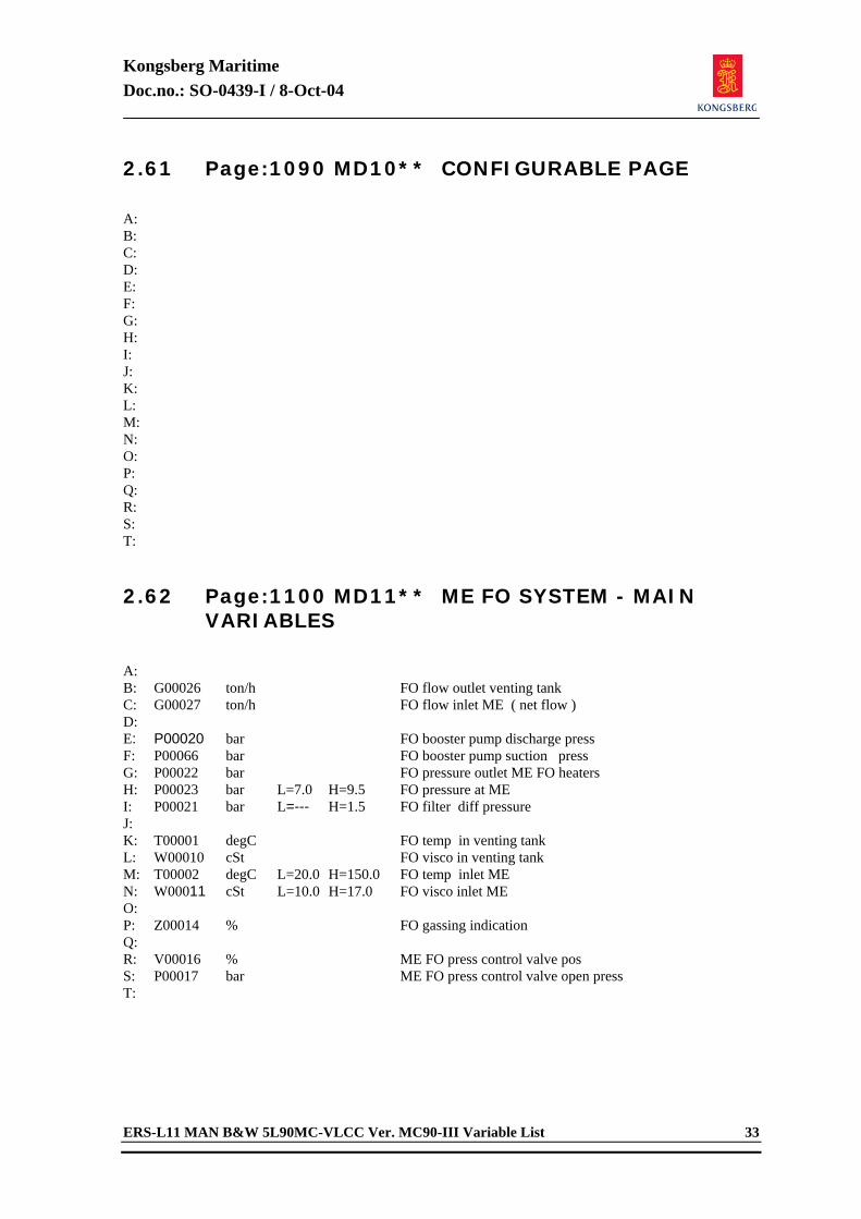
Kongsberg Maritime Doc.no.: SO-0439-I / 8-Oct-04
ERS-L11 MAN B&W 5L90MC-VLCC Ver. MC90-III Variable List 33
2.61 Page:1090 MD10** CONFIGURABLE PAGE
A: B: C: D: E: F: G: H: I: J: K: L: M: N: O: P: Q: R: S: T: 2.62 Page:1100 MD11** ME FO SYSTEM - MAIN
VARIABLES
A: B: G00026 ton/h FO flow outlet venting tank C: G00027 ton/h FO flow inlet ME ( net flow ) D: E: P00020 bar FO booster pump discharge press F: P00066 bar FO booster pump suction press G: P00022 bar FO pressure outlet ME FO heaters H: P00023 bar L=7.0 H=9.5 FO pressure at ME I: P00021 bar L=--- H=1.5 FO filter diff pressure J: K: T00001 degC FO temp in venting tank L: W00010 cSt FO visco in venting tank M: T00002 degC L=20.0 H=150.0 FO temp inlet ME N: W00011 cSt L=10.0 H=17.0 FO visco inlet ME O: P: Z00014 % FO gassing indication Q: R: V00016 % ME FO press control valve pos S: P00017 bar ME FO press control valve open press T:
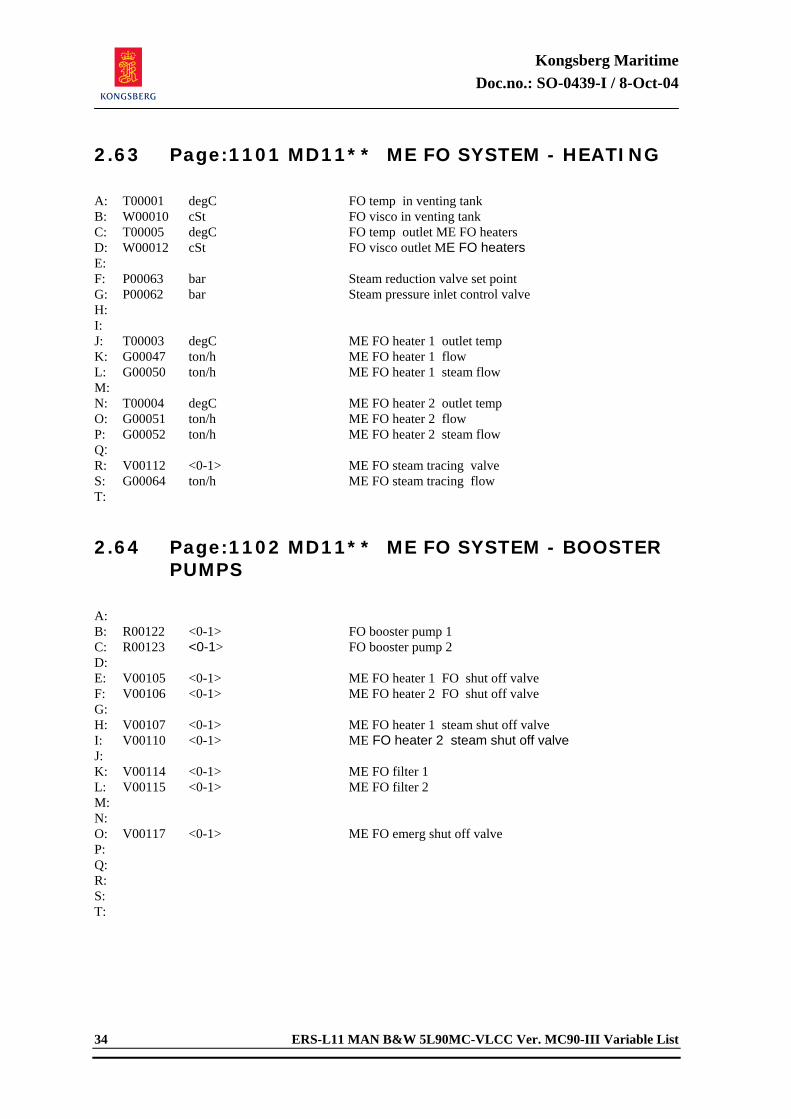
Kongsberg Maritime Doc.no.: SO-0439-I / 8-Oct-04
34 ERS-L11 MAN B&W 5L90MC-VLCC Ver. MC90-III Variable List
2.63 Page:1101 MD11** ME FO SYSTEM - HEATING
A: T00001 degC FO temp in venting tank B: W00010 cSt FO visco in venting tank C: T00005 degC FO temp outlet ME FO heaters D: W00012 cSt FO visco outlet ME FO heaters E: F: P00063 bar Steam reduction valve set point G: P00062 bar Steam pressure inlet control valve H: I: J: T00003 degC ME FO heater 1 outlet temp K: G00047 ton/h ME FO heater 1 flow L: G00050 ton/h ME FO heater 1 steam flow M: N: T00004 degC ME FO heater 2 outlet temp O: G00051 ton/h ME FO heater 2 flow P: G00052 ton/h ME FO heater 2 steam flow Q: R: V00112 <0-1> ME FO steam tracing valve S: G00064 ton/h ME FO steam tracing flow T: 2.64 Page:1102 MD11** ME FO SYSTEM - BOOSTER
PUMPS
A: B: R00122 <0-1> FO booster pump 1 C: R00123 <0-1> FO booster pump 2 D: E: V00105 <0-1> ME FO heater 1 FO shut off valve F: V00106 <0-1> ME FO heater 2 FO shut off valve G: H: V00107 <0-1> ME FO heater 1 steam shut off valve I: V00110 <0-1> ME FO heater 2 steam shut off valve J: K: V00114 <0-1> ME FO filter 1 L: V00115 <0-1> ME FO filter 2 M: N: O: V00117 <0-1> ME FO emerg shut off valve P: Q: R: S: T:
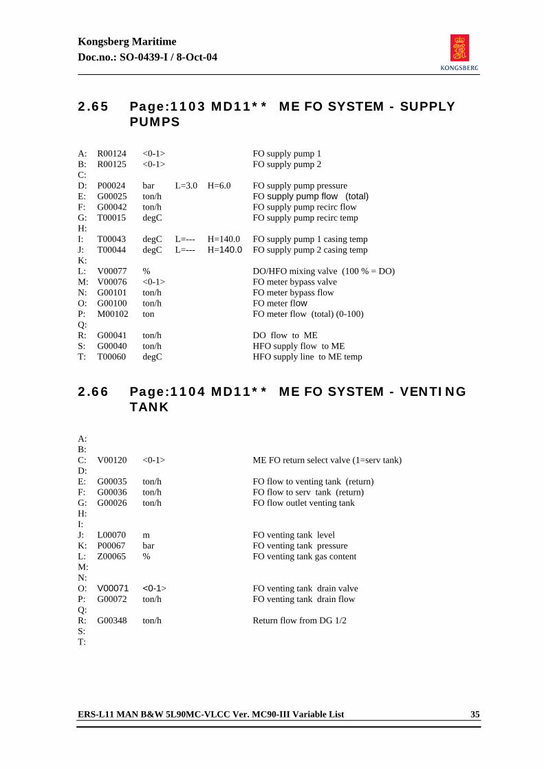
Kongsberg Maritime Doc.no.: SO-0439-I / 8-Oct-04
ERS-L11 MAN B&W 5L90MC-VLCC Ver. MC90-III Variable List 35
2.65 Page:1103 MD11** ME FO SYSTEM - SUPPLY PUMPS
A: R00124 <0-1> FO supply pump 1 B: R00125 <0-1> FO supply pump 2 C: D: P00024 bar L=3.0 H=6.0 FO supply pump pressure E: G00025 ton/h FO supply pump flow (total) F: G00042 ton/h FO supply pump recirc flow G: T00015 degC FO supply pump recirc temp H: I: T00043 degC L=--- H=140.0 FO supply pump 1 casing temp J: T00044 degC L=--- H=140.0 FO supply pump 2 casing temp K: L: V00077 % DO/HFO mixing valve (100 % = DO) M: V00076 <0-1> FO meter bypass valve N: G00101 ton/h FO meter bypass flow O: G00100 ton/h FO meter flow P: M00102 ton FO meter flow (total) (0-100) Q: R: G00041 ton/h DO flow to ME S: G00040 ton/h HFO supply flow to ME T: T00060 degC HFO supply line to ME temp 2.66 Page:1104 MD11** ME FO SYSTEM - VENTING
TANK
A: B: C: V00120 <0-1> ME FO return select valve (1=serv tank) D: E: G00035 ton/h FO flow to venting tank (return) F: G00036 ton/h FO flow to serv tank (return) G: G00026 ton/h FO flow outlet venting tank H: I: J: L00070 m FO venting tank level K: P00067 bar FO venting tank pressure L: Z00065 % FO venting tank gas content M: N: O: V00071 <0-1> FO venting tank drain valve P: G00072 ton/h FO venting tank drain flow Q: R: G00348 ton/h Return flow from DG 1/2 S: T:
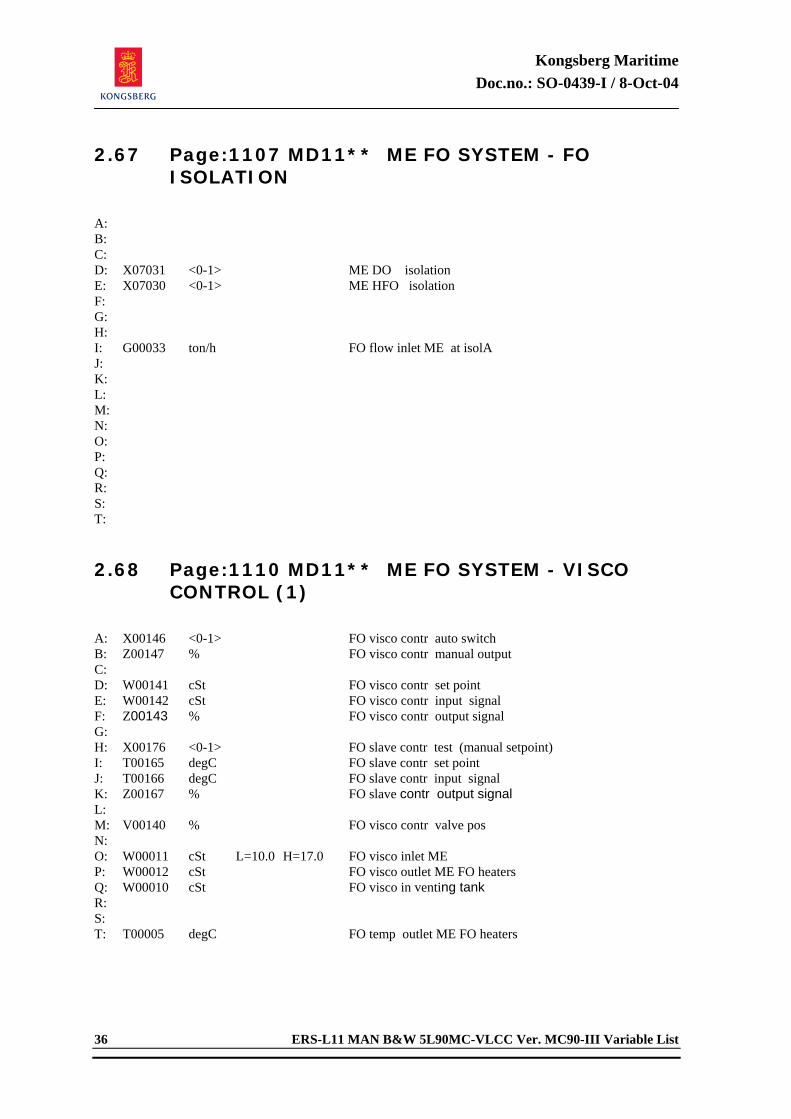
Kongsberg Maritime Doc.no.: SO-0439-I / 8-Oct-04
36 ERS-L11 MAN B&W 5L90MC-VLCC Ver. MC90-III Variable List
2.67 Page:1107 MD11** ME FO SYSTEM - FO ISOLATION
A: B: C: D: X07031 <0-1> ME DO isolation E: X07030 <0-1> ME HFO isolation F: G: H: I: G00033 ton/h FO flow inlet ME at isolA J: K: L: M: N: O: P: Q: R: S: T: 2.68 Page:1110 MD11** ME FO SYSTEM - VISCO
CONTROL (1)
A: X00146 <0-1> FO visco contr auto switch B: Z00147 % FO visco contr manual output C: D: W00141 cSt FO visco contr set point E: W00142 cSt FO visco contr input signal F: Z00143 % FO visco contr output signal G: H: X00176 <0-1> FO slave contr test (manual setpoint) I: T00165 degC FO slave contr set point J: T00166 degC FO slave contr input signal K: Z00167 % FO slave contr output signal L: M: V00140 % FO visco contr valve pos N: O: W00011 cSt L=10.0 H=17.0 FO visco inlet ME P: W00012 cSt FO visco outlet ME FO heaters Q: W00010 cSt FO visco in venting tank R: S: T: T00005 degC FO temp outlet ME FO heaters
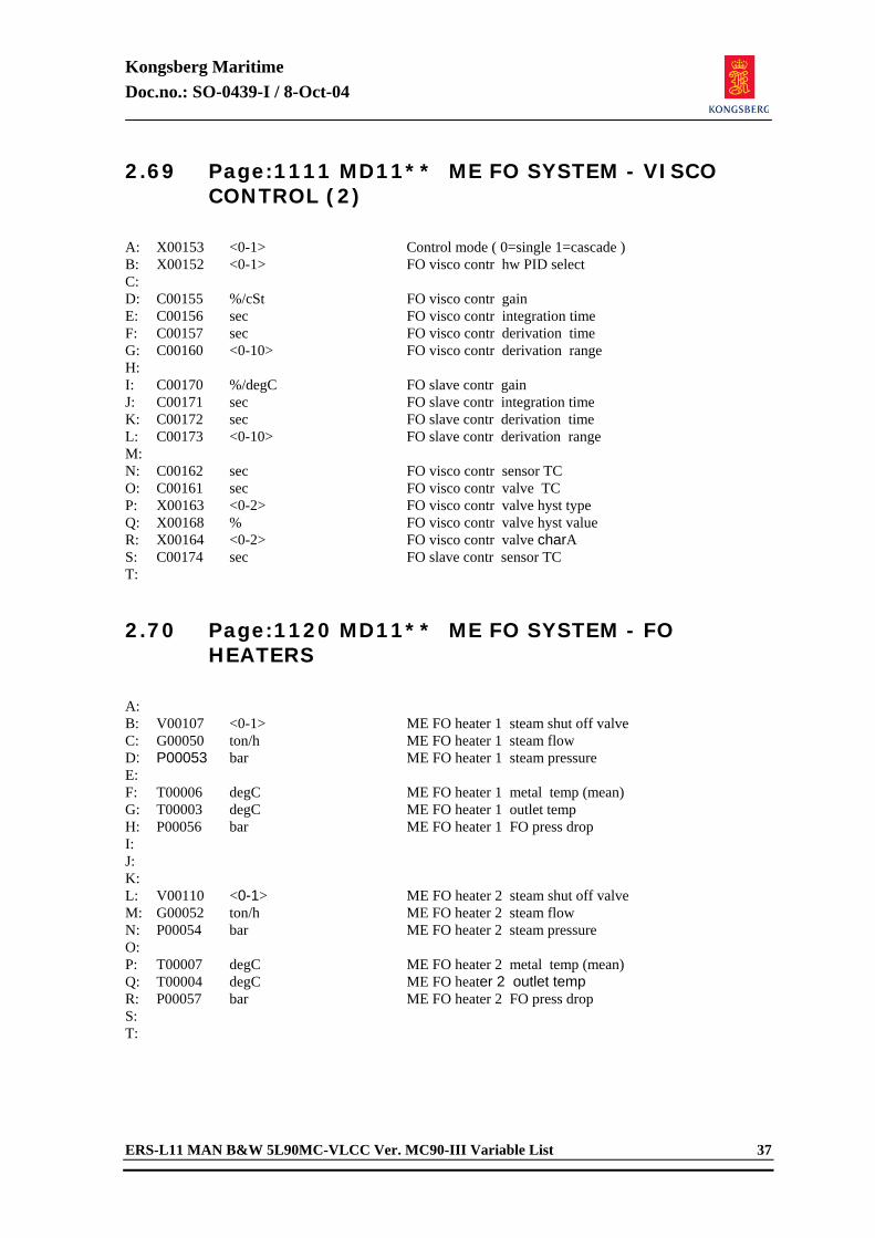
Kongsberg Maritime Doc.no.: SO-0439-I / 8-Oct-04
ERS-L11 MAN B&W 5L90MC-VLCC Ver. MC90-III Variable List 37
2.69 Page:1111 MD11** ME FO SYSTEM - VISCO CONTROL (2)
A: X00153 <0-1> Control mode ( 0=single 1=cascade ) B: X00152 <0-1> FO visco contr hw PID select C: D: C00155 %/cSt FO visco contr gain E: C00156 sec FO visco contr integration time F: C00157 sec FO visco contr derivation time G: C00160 <0-10> FO visco contr derivation range H: I: C00170 %/degC FO slave contr gain J: C00171 sec FO slave contr integration time K: C00172 sec FO slave contr derivation time L: C00173 <0-10> FO slave contr derivation range M: N: C00162 sec FO visco contr sensor TC O: C00161 sec FO visco contr valve TC P: X00163 <0-2> FO visco contr valve hyst type Q: X00168 % FO visco contr valve hyst value R: X00164 <0-2> FO visco contr valve charA S: C00174 sec FO slave contr sensor TC T: 2.70 Page:1120 MD11** ME FO SYSTEM - FO
HEATERS
A: B: V00107 <0-1> ME FO heater 1 steam shut off valve C: G00050 ton/h ME FO heater 1 steam flow D: P00053 bar ME FO heater 1 steam pressure E: F: T00006 degC ME FO heater 1 metal temp (mean) G: T00003 degC ME FO heater 1 outlet temp H: P00056 bar ME FO heater 1 FO press drop I: J: K: L: V00110 <0-1> ME FO heater 2 steam shut off valve M: G00052 ton/h ME FO heater 2 steam flow N: P00054 bar ME FO heater 2 steam pressure O: P: T00007 degC ME FO heater 2 metal temp (mean) Q: T00004 degC ME FO heater 2 outlet temp R: P00057 bar ME FO heater 2 FO press drop S: T:
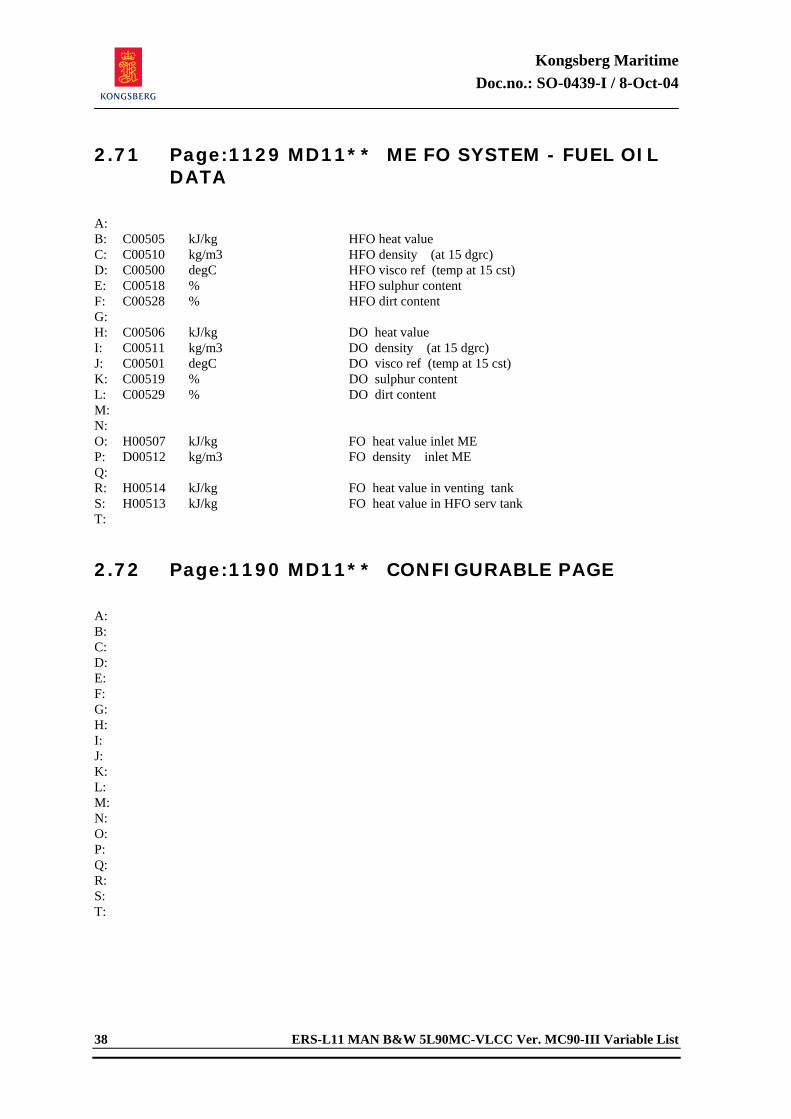
Kongsberg Maritime Doc.no.: SO-0439-I / 8-Oct-04
38 ERS-L11 MAN B&W 5L90MC-VLCC Ver. MC90-III Variable List
2.71 Page:1129 MD11** ME FO SYSTEM - FUEL OIL DATA
A: B: C00505 kJ/kg HFO heat value C: C00510 kg/m3 HFO density (at 15 dgrc) D: C00500 degC HFO visco ref (temp at 15 cst) E: C00518 % HFO sulphur content F: C00528 % HFO dirt content G: H: C00506 kJ/kg DO heat value I: C00511 kg/m3 DO density (at 15 dgrc) J: C00501 degC DO visco ref (temp at 15 cst) K: C00519 % DO sulphur content L: C00529 % DO dirt content M: N: O: H00507 kJ/kg FO heat value inlet ME P: D00512 kg/m3 FO density inlet ME Q: R: H00514 kJ/kg FO heat value in venting tank S: H00513 kJ/kg FO heat value in HFO serv tank T: 2.72 Page:1190 MD11** CONFIGURABLE PAGE
A: B: C: D: E: F: G: H: I: J: K: L: M: N: O: P: Q: R: S: T:
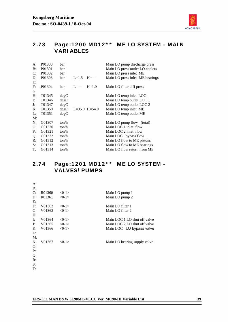
Kongsberg Maritime Doc.no.: SO-0439-I / 8-Oct-04
ERS-L11 MAN B&W 5L90MC-VLCC Ver. MC90-III Variable List 39
2.73 Page:1200 MD12** ME LO SYSTEM - MAIN VARIABLES
A: P01300 bar Main LO pump discharge press B: P01301 bar Main LO press outlet LO coolers C: P01302 bar Main LO press inlet ME D: P01303 bar L=1.5 H=--- Main LO press inlet ME bearings E: F: P01304 bar L=--- H=1.0 Main LO filter diff press G: H: T01345 degC Main LO temp inlet LOC I: T01346 degC Main LO temp outlet LOC 1 J: T01347 degC Main LO temp outlet LOC 2 K: T01350 degC L=35.0 H=54.0 Main LO temp inlet ME L: T01351 degC Main LO temp outlet ME M: N: G01307 ton/h Main LO pump flow (total) O: G01320 ton/h Main LOC 1 inlet flow P: G01321 ton/h Main LOC 2 inlet flow Q: G01322 ton/h Main LOC bypass flow R: G01312 ton/h Main LO flow to ME pistons S: G01313 ton/h Main LO flow to ME bearings T: G01314 ton/h Main LO flow return from ME 2.74 Page:1201 MD12** ME LO SYSTEM -
VALVES/PUMPS
A: B: C: R01360 <0-1> Main LO pump 1 D: R01361 <0-1> Main LO pump 2 E: F: V01362 <0-1> Main LO filter 1 G: V01363 <0-1> Main LO filter 2 H: I: V01364 <0-1> Main LOC 1 LO shut off valve J: V01365 <0-1> Main LOC 2 LO shut off valve K: V01366 <0-1> Main LOC LO bypass valve L: M: N: V01367 <0-1> Main LO bearing supply valve O: P: Q: R: S: T:
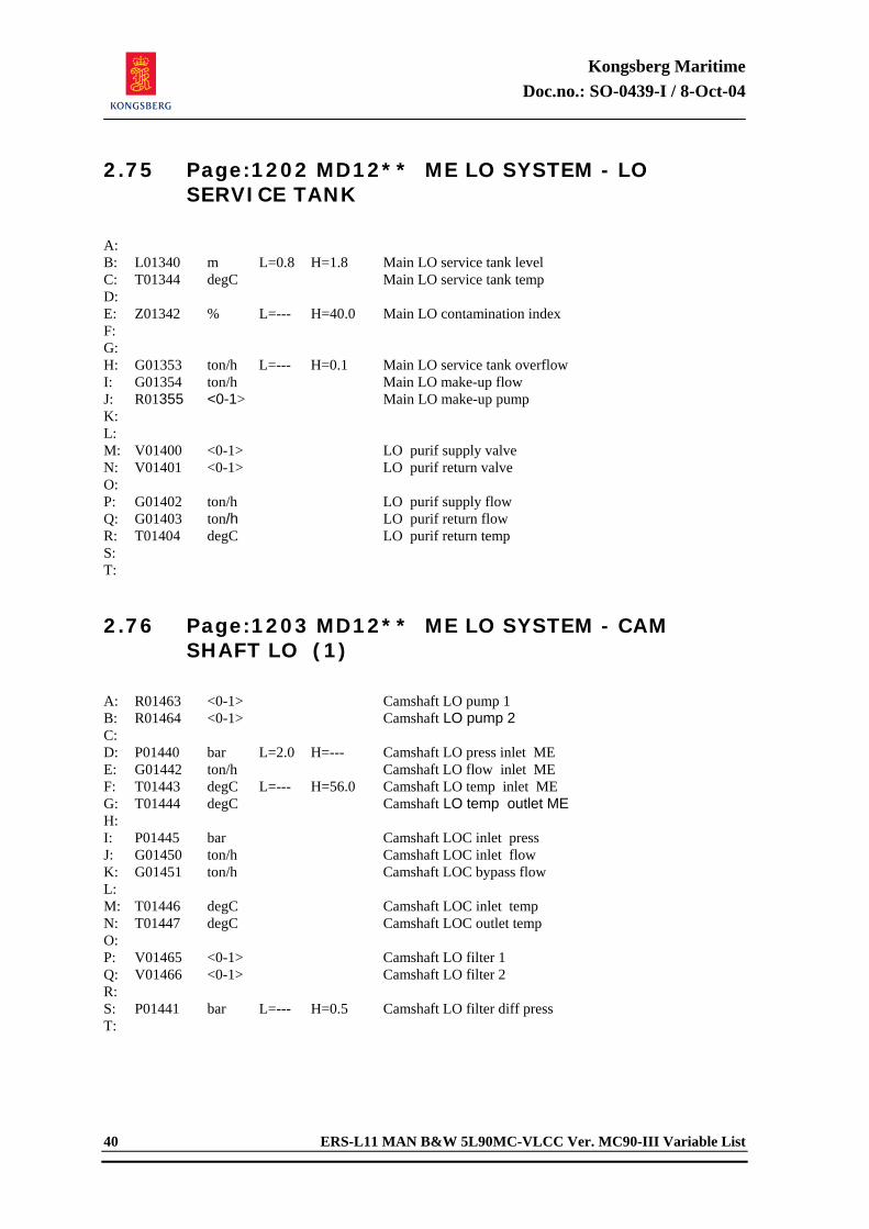
Kongsberg Maritime Doc.no.: SO-0439-I / 8-Oct-04
40 ERS-L11 MAN B&W 5L90MC-VLCC Ver. MC90-III Variable List
2.75 Page:1202 MD12** ME LO SYSTEM - LO SERVICE TANK
A: B: L01340 m L=0.8 H=1.8 Main LO service tank level C: T01344 degC Main LO service tank temp D: E: Z01342 % L=--- H=40.0 Main LO contamination index F: G: H: G01353 ton/h L=--- H=0.1 Main LO service tank overflow I: G01354 ton/h Main LO make-up flow J: R01355 <0-1> Main LO make-up pump K: L: M: V01400 <0-1> LO purif supply valve N: V01401 <0-1> LO purif return valve O: P: G01402 ton/h LO purif supply flow Q: G01403 ton/h LO purif return flow R: T01404 degC LO purif return temp S: T: 2.76 Page:1203 MD12** ME LO SYSTEM - CAM
SHAFT LO (1)
A: R01463 <0-1> Camshaft LO pump 1 B: R01464 <0-1> Camshaft LO pump 2 C: D: P01440 bar L=2.0 H=--- Camshaft LO press inlet ME E: G01442 ton/h Camshaft LO flow inlet ME F: T01443 degC L=--- H=56.0 Camshaft LO temp inlet ME G: T01444 degC Camshaft LO temp outlet ME H: I: P01445 bar Camshaft LOC inlet press J: G01450 ton/h Camshaft LOC inlet flow K: G01451 ton/h Camshaft LOC bypass flow L: M: T01446 degC Camshaft LOC inlet temp N: T01447 degC Camshaft LOC outlet temp O: P: V01465 <0-1> Camshaft LO filter 1 Q: V01466 <0-1> Camshaft LO filter 2 R: S: P01441 bar L=--- H=0.5 Camshaft LO filter diff press T:
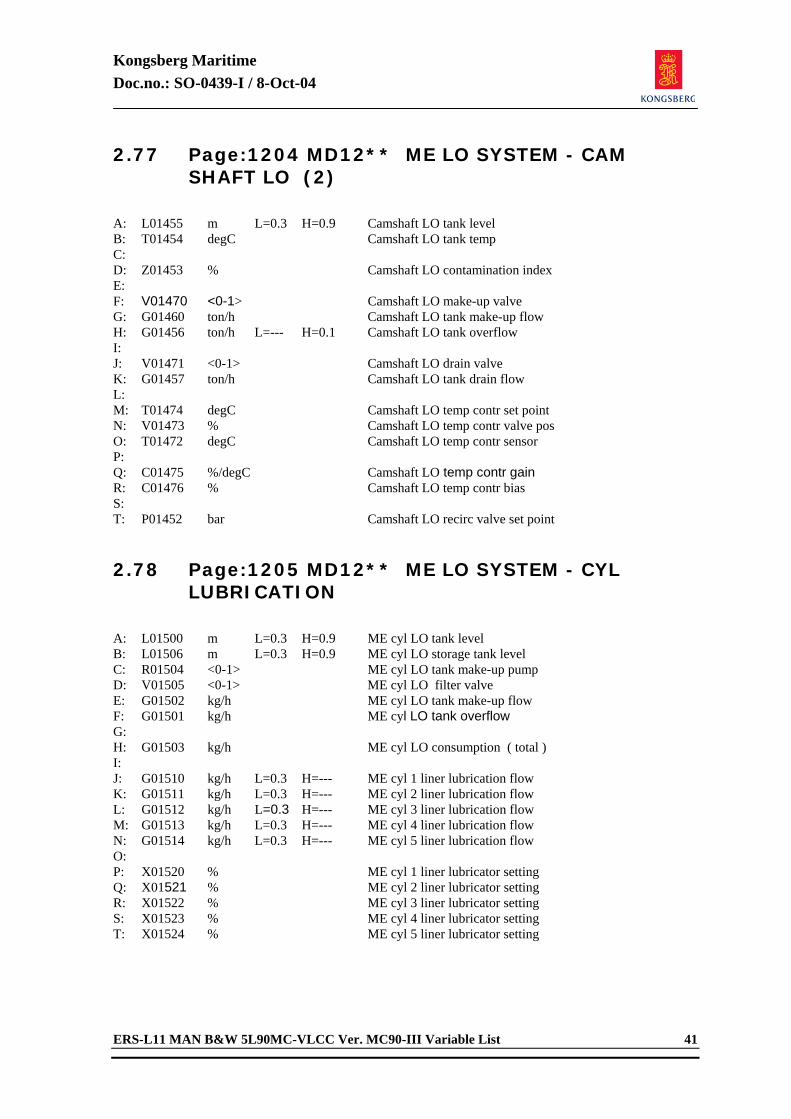
Kongsberg Maritime Doc.no.: SO-0439-I / 8-Oct-04
ERS-L11 MAN B&W 5L90MC-VLCC Ver. MC90-III Variable List 41
2.77 Page:1204 MD12** ME LO SYSTEM - CAM SHAFT LO (2)
A: L01455 m L=0.3 H=0.9 Camshaft LO tank level B: T01454 degC Camshaft LO tank temp C: D: Z01453 % Camshaft LO contamination index E: F: V01470 <0-1> Camshaft LO make-up valve G: G01460 ton/h Camshaft LO tank make-up flow H: G01456 ton/h L=--- H=0.1 Camshaft LO tank overflow I: J: V01471 <0-1> Camshaft LO drain valve K: G01457 ton/h Camshaft LO tank drain flow L: M: T01474 degC Camshaft LO temp contr set point N: V01473 % Camshaft LO temp contr valve pos O: T01472 degC Camshaft LO temp contr sensor P: Q: C01475 %/degC Camshaft LO temp contr gain R: C01476 % Camshaft LO temp contr bias S: T: P01452 bar Camshaft LO recirc valve set point 2.78 Page:1205 MD12** ME LO SYSTEM - CYL
LUBRICATION
A: L01500 m L=0.3 H=0.9 ME cyl LO tank level B: L01506 m L=0.3 H=0.9 ME cyl LO storage tank level C: R01504 <0-1> ME cyl LO tank make-up pump D: V01505 <0-1> ME cyl LO filter valve E: G01502 kg/h ME cyl LO tank make-up flow F: G01501 kg/h ME cyl LO tank overflow G: H: G01503 kg/h ME cyl LO consumption ( total ) I: J: G01510 kg/h L=0.3 H=--- ME cyl 1 liner lubrication flow K: G01511 kg/h L=0.3 H=--- ME cyl 2 liner lubrication flow L: G01512 kg/h L=0.3 H=--- ME cyl 3 liner lubrication flow M: G01513 kg/h L=0.3 H=--- ME cyl 4 liner lubrication flow N: G01514 kg/h L=0.3 H=--- ME cyl 5 liner lubrication flow O: P: X01520 % ME cyl 1 liner lubricator setting Q: X01521 % ME cyl 2 liner lubricator setting R: X01522 % ME cyl 3 liner lubricator setting S: X01523 % ME cyl 4 liner lubricator setting T: X01524 % ME cyl 5 liner lubricator setting
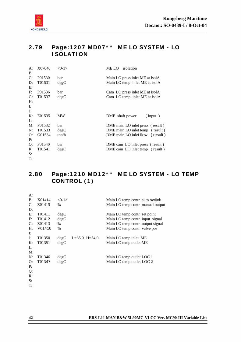
Kongsberg Maritime Doc.no.: SO-0439-I / 8-Oct-04
42 ERS-L11 MAN B&W 5L90MC-VLCC Ver. MC90-III Variable List
2.79 Page:1207 MD07** ME LO SYSTEM - LO ISOLATION
A: X07040 <0-1> ME LO isolation B: C: P01530 bar Main LO press inlet ME at isolA D: T01531 degC Main LO temp inlet ME at isolA E: F: P01536 bar Cam LO press inlet ME at isolA G: T01537 degC Cam LO temp inlet ME at isolA H: I: J: K: E01535 MW DME shaft power ( input ) L: M: P01532 bar DME main LO inlet press ( result ) N: T01533 degC DME main LO inlet temp ( result ) O: G01534 ton/h DME main LO inlet flow ( result ) P: Q: P01540 bar DME cam LO inlet press ( result ) R: T01541 degC DME cam LO inlet temp ( result ) S: T: 2.80 Page:1210 MD12** ME LO SYSTEM - LO TEMP
CONTROL (1)
A: B: X01414 <0-1> Main LO temp contr auto switch C: Z01415 % Main LO temp contr manual output D: E: T01411 degC Main LO temp contr set point F: T01412 degC Main LO temp contr input signal G: Z01413 % Main LO temp contr output signal H: V01410 % Main LO temp contr valve pos I: J: T01350 degC L=35.0 H=54.0 Main LO temp inlet ME K: T01351 degC Main LO temp outlet ME L: M: N: T01346 degC Main LO temp outlet LOC 1 O: T01347 degC Main LO temp outlet LOC 2 P: Q: R: S: T:
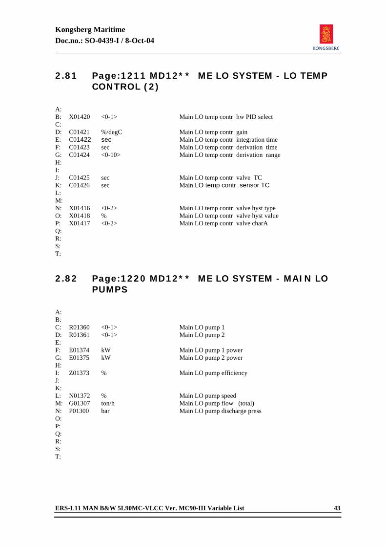
Kongsberg Maritime Doc.no.: SO-0439-I / 8-Oct-04
ERS-L11 MAN B&W 5L90MC-VLCC Ver. MC90-III Variable List 43
2.81 Page:1211 MD12** ME LO SYSTEM - LO TEMP CONTROL (2)
A: B: X01420 <0-1> Main LO temp contr hw PID select C: D: C01421 %/degC Main LO temp contr gain E: C01422 sec Main LO temp contr integration time F: C01423 sec Main LO temp contr derivation time G: C01424 <0-10> Main LO temp contr derivation range H: I: J: C01425 sec Main LO temp contr valve TC K: C01426 sec Main LO temp contr sensor TC L: M: N: X01416 <0-2> Main LO temp contr valve hyst type O: X01418 % Main LO temp contr valve hyst value P: X01417 <0-2> Main LO temp contr valve charA Q: R: S: T: 2.82 Page:1220 MD12** ME LO SYSTEM - MAIN LO
PUMPS
A: B: C: R01360 <0-1> Main LO pump 1 D: R01361 <0-1> Main LO pump 2 E: F: E01374 kW Main LO pump 1 power G: E01375 kW Main LO pump 2 power H: I: Z01373 % Main LO pump efficiency J: K: L: N01372 % Main LO pump speed M: G01307 ton/h Main LO pump flow (total) N: P01300 bar Main LO pump discharge press O: P: Q: R: S: T:
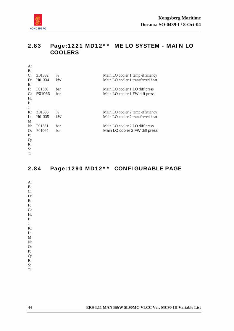
Kongsberg Maritime Doc.no.: SO-0439-I / 8-Oct-04
44 ERS-L11 MAN B&W 5L90MC-VLCC Ver. MC90-III Variable List
2.83 Page:1221 MD12** ME LO SYSTEM - MAIN LO COOLERS
A: B: C: Z01332 % Main LO cooler 1 temp efficiency D: H01334 kW Main LO cooler 1 transferred heat E: F: P01330 bar Main LO cooler 1 LO diff press G: P01063 bar Main LO cooler 1 FW diff press H: I: J: K: Z01333 % Main LO cooler 2 temp efficiency L: H01335 kW Main LO cooler 2 transferred heat M: N: P01331 bar Main LO cooler 2 LO diff press O: P01064 bar Main LO cooler 2 FW diff press P: Q: R: S: T: 2.84 Page:1290 MD12** CONFIGURABLE PAGE
A: B: C: D: E: F: G: H: I: J: K: L: M: N: O: P: Q: R: S: T:
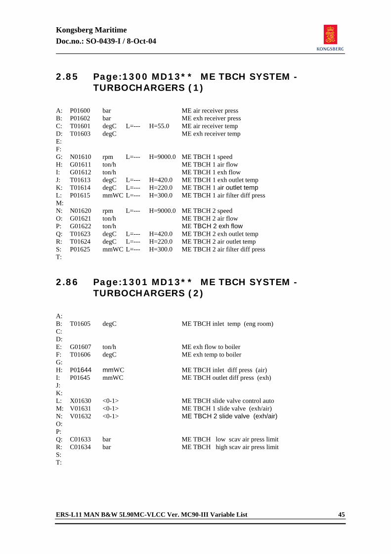
Kongsberg Maritime Doc.no.: SO-0439-I / 8-Oct-04
ERS-L11 MAN B&W 5L90MC-VLCC Ver. MC90-III Variable List 45
2.85 Page:1300 MD13** ME TBCH SYSTEM - TURBOCHARGERS (1)
A: P01600 bar ME air receiver press B: P01602 bar ME exh receiver press C: T01601 degC L=--- H=55.0 ME air receiver temp D: T01603 degC ME exh receiver temp E: F: G: N01610 rpm L=--- H=9000.0 ME TBCH 1 speed H: G01611 ton/h ME TBCH 1 air flow I: G01612 ton/h ME TBCH 1 exh flow J: T01613 degC L=--- H=420.0 ME TBCH 1 exh outlet temp K: T01614 degC L=--- H=220.0 ME TBCH 1 air outlet temp L: P01615 mmWC L=--- H=300.0 ME TBCH 1 air filter diff press M: N: N01620 rpm L=--- H=9000.0 ME TBCH 2 speed O: G01621 ton/h ME TBCH 2 air flow P: G01622 ton/h ME TBCH 2 exh flow Q: T01623 degC L=--- H=420.0 ME TBCH 2 exh outlet temp R: T01624 degC L=--- H=220.0 ME TBCH 2 air outlet temp S: P01625 mmWC L=--- H=300.0 ME TBCH 2 air filter diff press T: 2.86 Page:1301 MD13** ME TBCH SYSTEM -
TURBOCHARGERS (2)
A: B: T01605 degC ME TBCH inlet temp (eng room) C: D: E: G01607 ton/h ME exh flow to boiler F: T01606 degC ME exh temp to boiler G: H: P01644 mmWC ME TBCH inlet diff press (air) I: P01645 mmWC ME TBCH outlet diff press (exh) J: K: L: X01630 <0-1> ME TBCH slide valve control auto M: V01631 <0-1> ME TBCH 1 slide valve (exh/air) N: V01632 <0-1> ME TBCH 2 slide valve (exh/air) O: P: Q: C01633 bar ME TBCH low scav air press limit R: C01634 bar ME TBCH high scav air press limit S: T:
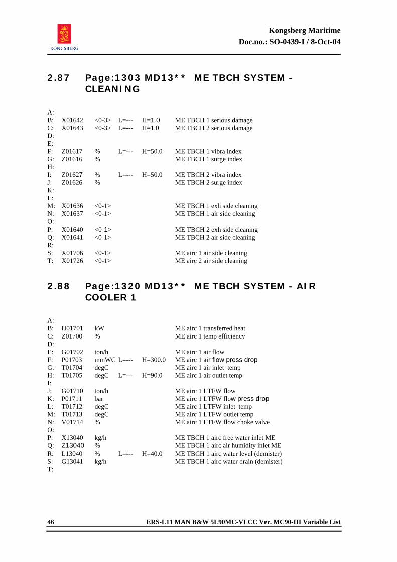
Kongsberg Maritime Doc.no.: SO-0439-I / 8-Oct-04
46 ERS-L11 MAN B&W 5L90MC-VLCC Ver. MC90-III Variable List
2.87 Page:1303 MD13** ME TBCH SYSTEM - CLEANING
A: B: X01642 <0-3> L=--- H=1.0 ME TBCH 1 serious damage C: X01643 <0-3> L=--- H=1.0 ME TBCH 2 serious damage D: E: F: Z01617 % L=--- H=50.0 ME TBCH 1 vibra index G: Z01616 % ME TBCH 1 surge index H: I: Z01627 % L=--- H=50.0 ME TBCH 2 vibra index J: Z01626 % ME TBCH 2 surge index K: L: M: X01636 <0-1> ME TBCH 1 exh side cleaning N: X01637 <0-1> ME TBCH 1 air side cleaning O: P: X01640 <0-1> ME TBCH 2 exh side cleaning Q: X01641 <0-1> ME TBCH 2 air side cleaning R: S: X01706 <0-1> ME airc 1 air side cleaning T: X01726 <0-1> ME airc 2 air side cleaning 2.88 Page:1320 MD13** ME TBCH SYSTEM - AIR
COOLER 1
A: B: H01701 kW ME airc 1 transferred heat C: Z01700 % ME airc 1 temp efficiency D: E: G01702 ton/h ME airc 1 air flow F: P01703 mmWC L=--- H=300.0 ME airc 1 air flow press drop G: T01704 degC ME airc 1 air inlet temp H: T01705 degC L=--- H=90.0 ME airc 1 air outlet temp I: J: G01710 ton/h ME airc 1 LTFW flow K: P01711 bar ME airc 1 LTFW flow press drop L: T01712 degC ME airc 1 LTFW inlet temp M: T01713 degC ME airc 1 LTFW outlet temp N: V01714 % ME airc 1 LTFW flow choke valve O: P: X13040 kg/h ME TBCH 1 airc free water inlet ME Q: Z13040 % ME TBCH 1 airc air humidity inlet ME R: L13040 % L=--- H=40.0 ME TBCH 1 airc water level (demister) S: G13041 kg/h ME TBCH 1 airc water drain (demister) T:
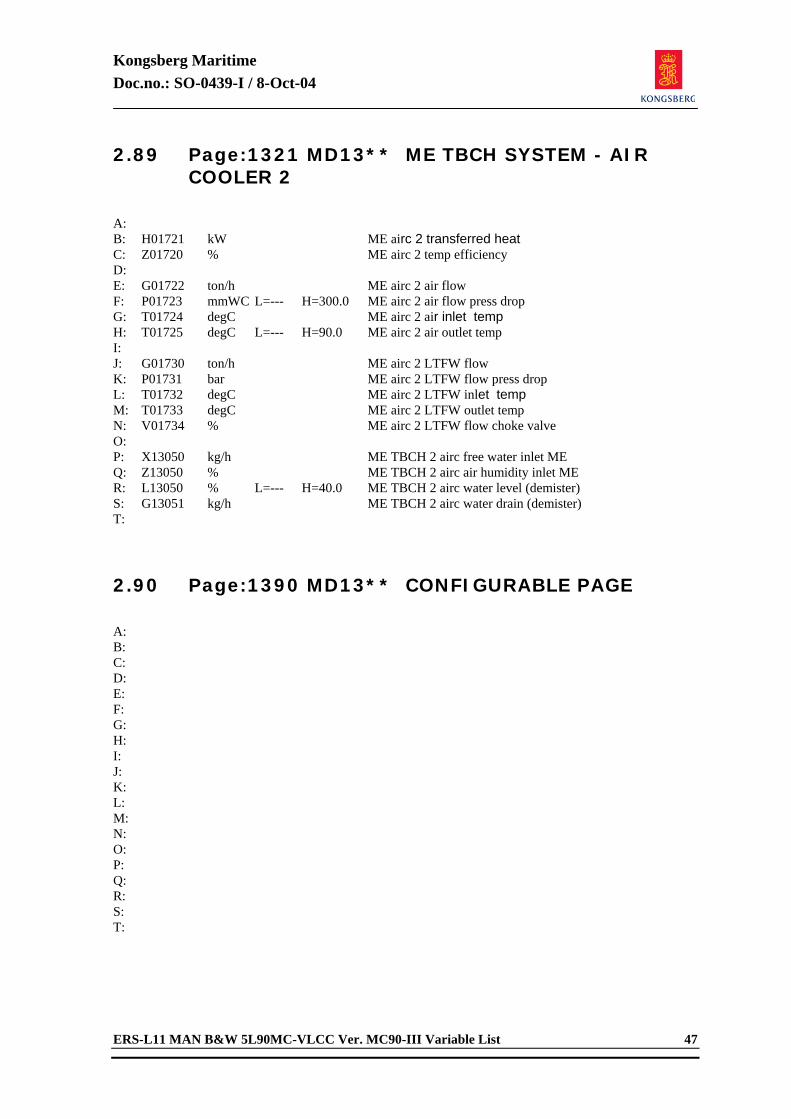
Kongsberg Maritime Doc.no.: SO-0439-I / 8-Oct-04
ERS-L11 MAN B&W 5L90MC-VLCC Ver. MC90-III Variable List 47
2.89 Page:1321 MD13** ME TBCH SYSTEM - AIR COOLER 2
A: B: H01721 kW ME airc 2 transferred heat C: Z01720 % ME airc 2 temp efficiency D: E: G01722 ton/h ME airc 2 air flow F: P01723 mmWC L=--- H=300.0 ME airc 2 air flow press drop G: T01724 degC ME airc 2 air inlet temp H: T01725 degC L=--- H=90.0 ME airc 2 air outlet temp I: J: G01730 ton/h ME airc 2 LTFW flow K: P01731 bar ME airc 2 LTFW flow press drop L: T01732 degC ME airc 2 LTFW inlet temp M: T01733 degC ME airc 2 LTFW outlet temp N: V01734 % ME airc 2 LTFW flow choke valve O: P: X13050 kg/h ME TBCH 2 airc free water inlet ME Q: Z13050 % ME TBCH 2 airc air humidity inlet ME R: L13050 % L=--- H=40.0 ME TBCH 2 airc water level (demister) S: G13051 kg/h ME TBCH 2 airc water drain (demister) T: 2.90 Page:1390 MD13** CONFIGURABLE PAGE
A: B: C: D: E: F: G: H: I: J: K: L: M: N: O: P: Q: R: S: T:
Kongsberg Maritime Doc.no.: SO-0439-I / 8-Oct-04
48 ERS-L11 MAN B&W 5L90MC-VLCC Ver. MC90-III Variable List
2.91 Page:1900 MD19** ME CONTROL SYSTEM - LOCAL CONTROL (1)
A: B: X02406 <0-1> Local fuel link control C: Z02405 % Local fuel link position command D: E: N02015 rpm L=--- H=82.0 ME speed F: X02010 % ME fuel link position G: P01600 bar ME air receiver press H: I: J: K: X02407 <0-1> ME cam position command (1=astern) L: M: X02417 <0-1> ME start air valve N: X02420 <0-1> ME start air slow turning O: P: Q: R: X02410 <0-1> ME start air block valve S: X02411 <0-1> ME start air distributor block valve T: 2.92 Page:1901 MD19** ME CONTROL SYSTEM -
LOCAL CONTROL (2)
A: B: C: X02413 <0-8> L=--- H=1.0 ME serious damage ( trip ) D: E: F: Z02414 <0-2> Crank case oil mist indication G: Z02415 <0-1> Crank case doors open (mist ventilate) H: I: V02416 <0-1> Scav air box fires extinguisher J: K: L: X02412 <0-1> ME turning gear M: N: V02063 <0-1> ME cyl 1 indicator cock O: V02123 <0-1> ME cyl 2 indicator cock P: V02163 <0-1> ME cyl 3 indicator cock Q: V02223 <0-1> ME cyl 4 indicator cock R: V02263 <0-1> ME cyl 5 indicator cock S: T:
Kongsberg Maritime Doc.no.: SO-0439-I / 8-Oct-04
ERS-L11 MAN B&W 5L90MC-VLCC Ver. MC90-III Variable List 49
2.93 Page:1910 MD19** ME CONTROL SYSTEM - REMOTE CONTROL (1)
A: Z02400 % Control lever pos (ec/br) B: C: N02401 rpm ME speed command (final) D: N02015 rpm L=--- H=82.0 ME speed E: F: X02402 P/D Propeller pitch command G: X03762 P/D Propeller pitch H: Z02403 % Propeller pitch reduction index I: J: K: X07521 <0-1> ME control mode : Fixed pitch L: X07522 <0-1> ME control mode : Combinator M: X07524 <0-1> ME control mode : Economy N: X07525 <0-1> ME control mode : Shaft gen O: X07523 <0-1> ME control mode : Fixed speed P: Q: Z02422 <0-1> Autochief command : Cam ahead R: Z02423 <0-1> Autochief command : Cam astern S: Z02424 <0-1> Autochief command : Fuel stop T: Z02425 <0-1> Autochief command : Start air on 2.94 Page:1911 MD19** ME CONTROL SYSTEM -
REMOTE CONTROL (2)
A: X07526 <0-1> ME operation : Start/stop (combi) B: C: X02430 % Autochief : Rpm/pitch com (actual) D: X02431 % Autochief : Rpm/pitch com (limit ) E: X02432 % Autochief : Fuel link com (actual) F: X02433 % Autochief : Fuel link com (limit ) G: X02434 % Autochief : Thermal index H: I: Z02436 <0-1> Autochief : Rpm decrease J: Z02437 <0-1> Autochief : Rpm increase K: L: Z02440 <0-1> Autochief : Scav air limit (load red) M: Z02441 <0-1> Autochief : Torque limit (load red) N: Z02435 <0-1> Autochief : Thermal limit (load red) O: P: X02428 % Autochief : Fuel link start value Q: R: N07110 rpm Autochief speed command adjust (max) S: T: X02421 <0-7> Autochief state indication
Kongsberg Maritime Doc.no.: SO-0439-I / 8-Oct-04
50 ERS-L11 MAN B&W 5L90MC-VLCC Ver. MC90-III Variable List
2.95 Page:1912 MD19** ME CONTROL SYSTEM - REMOTE CONTROL (3)
A: X02444 <0-2> L=--- H=1.0 Autochief : Shut down B: Z02454 <0-1> Shutd 1 : Low-low bearing LO press C: Z02455 <0-1> Shutd 2 : Hig-hig thrust bearing temp D: Z02456 <0-1> Shutd 3 : Hig-hig cyl coolw temp E: Z02457 <0-1> Shutd 4 : ME overspeed F: Z02460 <0-1> Shutd 5 : Turning gear engaged G: H: X02445 <0-2> L=--- H=1.0 Autochief : Slow down I: Z02461 <0-1> Slowd 1 : Low bearing LO press J: Z02462 <0-1> Slowd 2 : High thrust bearing temp K: Z02463 <0-1> Slowd 3 : Low piston cool oil flow L: Z02464 <0-1> Slowd 4 : High scavenging air temp M: Z02465 <0-8> Slowd 5 : Miscellaneous N: O: X02446 <0-2> L=--- H=1.0 Autochief : Fail P: Z02447 <0-1> Fail 1 : Starting fail Q: Z02450 <0-1> Fail 2 : Reversing fail R: Z02451 <0-1> Fail 3 : Braking fail S: Z02452 <0-1> Fail 4 : Low start air pressure T: Z02453 <0-1> Fail 5 : Low control air pressure 2.96 Page:1913 MD19** ME CONTROL SYSTEM -
REMOTE CONTROL (4)
A: B: C: X02470 <0-1> ME auxil air blower auto D: E: R02471 <0-1> ME auxil air blower 1 F: R02472 <0-1> ME auxil air blower 2 G: H: I: J: N02404 rpm Fixed speed set point K: L: M: N: X07527 <0-1> ME operation : Direct fl control O: X07530 <0-1> ME operation : Locked fl control P: Q: R: S: T:

Kongsberg Maritime Doc.no.: SO-0439-I / 8-Oct-04
ERS-L11 MAN B&W 5L90MC-VLCC Ver. MC90-III Variable List 51
2.97 Page:1914 MD19** ME CONTROL SYSTEM - REMOTE CONTROL (5)
A: B: X01951 <0-1> ME shut down prewarning C: X01952 <0-1> ME slow down prewarning D: X01953 <0-1> ME thermal load program active E: X01954 <0-1> ME scav air/torque limit active F: G: X01961 <0-1> ME shut down override H: X01962 <0-1> ME slow down override I: X01963 <0-1> ME thermal load program cancel J: X01964 <0-1> ME scav air/torque limit cancel K: L: Z01960 sec ME shut down count down time M: Z01961 sec ME slow down count down time N: O: C01960 sec ME shut down prewarning time limit P: C01961 sec ME slow down prewarning time limit Q: R: S: T: 2.98 Page:1915 MD19** ME CONTROL SYSTEM -
REMOTE CONTROL (6)
A: B: C: D: E: F: C11921 <0-3> AC SHD 1 spec : 1=no override,2=no delay G: C11922 <0-3> AC SHD 2 spec : (3=1+2) H: C11923 <0-3> AC SHD 3 spec : I: C11924 <0-3> AC SHD 4 spec : J: C11925 <0-3> AC SHD 5 spec : K: C11931 <0-3> AC SLD 1 spec : 1=no override,2=no delay L: C11932 <0-3> AC SLD 2 spec : (3=1+2) M: C11933 <0-3> AC SLD 3 spec : N: C11934 <0-3> AC SLD 4 spec : O: C11935 <0-3> AC SLD 5 spec : P: Q: R: S: T:
Kongsberg Maritime Doc.no.: SO-0439-I / 8-Oct-04
52 ERS-L11 MAN B&W 5L90MC-VLCC Ver. MC90-III Variable List
2.99 Page:1920 MD19** ME CONTROL SYSTEM - EMERGENCY CONTROL
A: B: X07500 <0-2> Responsibility transfer : Bridge C: X07501 <0-2> Responsibility transfer : ECR D: X07502 <0-2> Responsibility transfer : Local E: F: X07503 <0-2> Stand by telegraph : ECR stand by G: X07504 <0-2> Stand by telegraph : Finished w eng H: I: J: X07510 <0-2> Emergency telegraph : Full ahead K: X07511 <0-2> Emergency telegraph : Half ahead L: X07512 <0-2> Emergency telegraph : Slow ahead M: X07513 <0-2> Emergency telegraph : Deads ahead N: X07514 <0-2> Emergency telegraph : Stop O: X07515 <0-2> Emergency telegraph : Deads astern P: X07516 <0-2> Emergency telegraph : Slow astern Q: X07517 <0-2> Emergency telegraph : Half astern R: X07520 <0-2> Emergency telegraph : Full astern S: T: 2.100 Page:1990 MD19** CONFIGURABLE PAGE
A: B: C: D: E: F: G: H: I: J: K: L: M: N: O: P: Q: R: S: T:
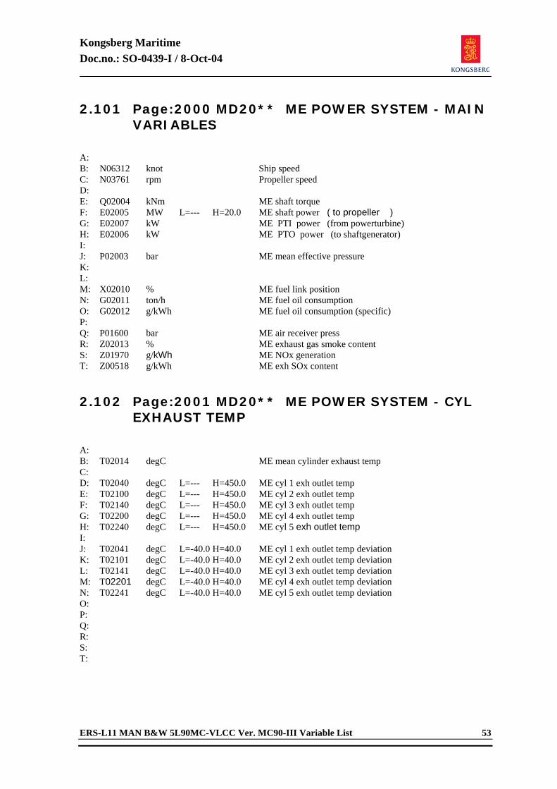
Kongsberg Maritime Doc.no.: SO-0439-I / 8-Oct-04
ERS-L11 MAN B&W 5L90MC-VLCC Ver. MC90-III Variable List 53
2.101 Page:2000 MD20** ME POWER SYSTEM - MAIN VARIABLES
A: B: N06312 knot Ship speed C: N03761 rpm Propeller speed D: E: Q02004 kNm ME shaft torque F: E02005 MW L=--- H=20.0 ME shaft power ( to propeller ) G: E02007 kW ME PTI power (from powerturbine) H: E02006 kW ME PTO power (to shaftgenerator) I: J: P02003 bar ME mean effective pressure K: L: M: X02010 % ME fuel link position N: G02011 ton/h ME fuel oil consumption O: G02012 g/kWh ME fuel oil consumption (specific) P: Q: P01600 bar ME air receiver press R: Z02013 % ME exhaust gas smoke content S: Z01970 g/kWh ME NOx generation T: Z00518 g/kWh ME exh SOx content 2.102 Page:2001 MD20** ME POWER SYSTEM - CYL
EXHAUST TEMP
A: B: T02014 degC ME mean cylinder exhaust temp C: D: T02040 degC L=--- H=450.0 ME cyl 1 exh outlet temp E: T02100 degC L=--- H=450.0 ME cyl 2 exh outlet temp F: T02140 degC L=--- H=450.0 ME cyl 3 exh outlet temp G: T02200 degC L=--- H=450.0 ME cyl 4 exh outlet temp H: T02240 degC L=--- H=450.0 ME cyl 5 exh outlet temp I: J: T02041 degC L=-40.0 H=40.0 ME cyl 1 exh outlet temp deviation K: T02101 degC L=-40.0 H=40.0 ME cyl 2 exh outlet temp deviation L: T02141 degC L=-40.0 H=40.0 ME cyl 3 exh outlet temp deviation M: T02201 degC L=-40.0 H=40.0 ME cyl 4 exh outlet temp deviation N: T02241 degC L=-40.0 H=40.0 ME cyl 5 exh outlet temp deviation O: P: Q: R: S: T:
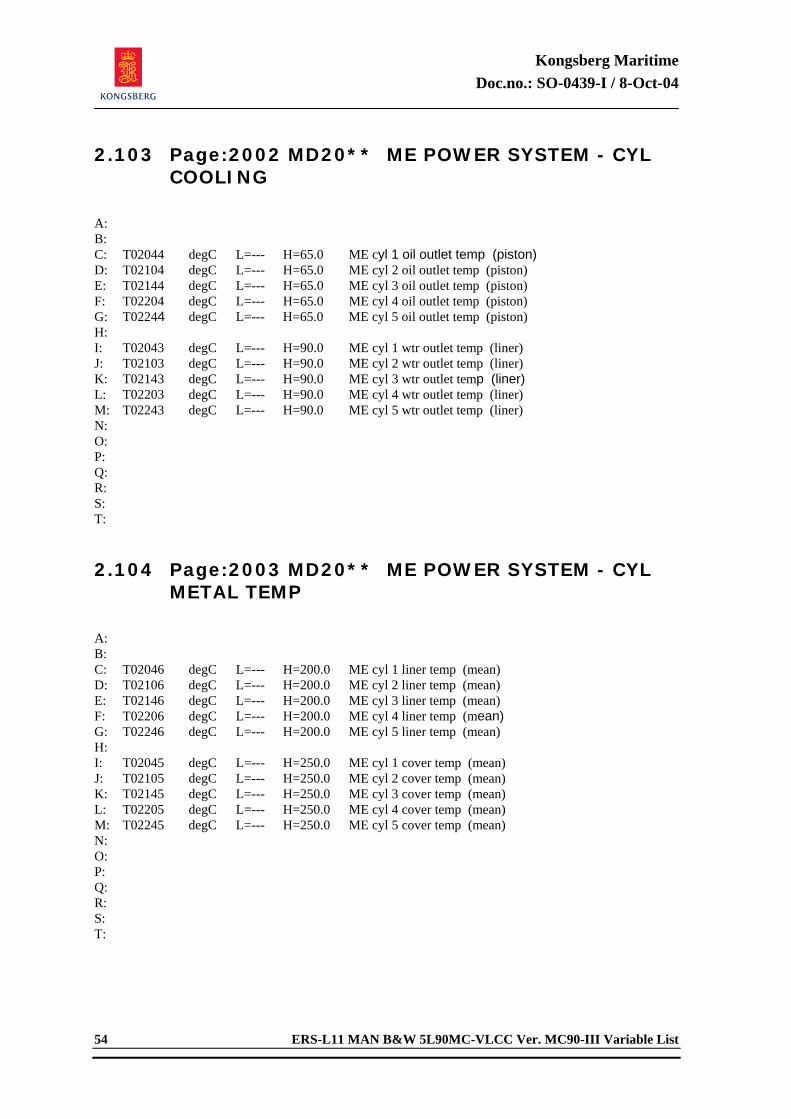
Kongsberg Maritime Doc.no.: SO-0439-I / 8-Oct-04
54 ERS-L11 MAN B&W 5L90MC-VLCC Ver. MC90-III Variable List
2.103 Page:2002 MD20** ME POWER SYSTEM - CYL COOLING
A: B: C: T02044 degC L=--- H=65.0 ME cyl 1 oil outlet temp (piston) D: T02104 degC L=--- H=65.0 ME cyl 2 oil outlet temp (piston) E: T02144 degC L=--- H=65.0 ME cyl 3 oil outlet temp (piston) F: T02204 degC L=--- H=65.0 ME cyl 4 oil outlet temp (piston) G: T02244 degC L=--- H=65.0 ME cyl 5 oil outlet temp (piston) H: I: T02043 degC L=--- H=90.0 ME cyl 1 wtr outlet temp (liner) J: T02103 degC L=--- H=90.0 ME cyl 2 wtr outlet temp (liner) K: T02143 degC L=--- H=90.0 ME cyl 3 wtr outlet temp (liner) L: T02203 degC L=--- H=90.0 ME cyl 4 wtr outlet temp (liner) M: T02243 degC L=--- H=90.0 ME cyl 5 wtr outlet temp (liner) N: O: P: Q: R: S: T: 2.104 Page:2003 MD20** ME POWER SYSTEM - CYL
METAL TEMP
A: B: C: T02046 degC L=--- H=200.0 ME cyl 1 liner temp (mean) D: T02106 degC L=--- H=200.0 ME cyl 2 liner temp (mean) E: T02146 degC L=--- H=200.0 ME cyl 3 liner temp (mean) F: T02206 degC L=--- H=200.0 ME cyl 4 liner temp (mean) G: T02246 degC L=--- H=200.0 ME cyl 5 liner temp (mean) H: I: T02045 degC L=--- H=250.0 ME cyl 1 cover temp (mean) J: T02105 degC L=--- H=250.0 ME cyl 2 cover temp (mean) K: T02145 degC L=--- H=250.0 ME cyl 3 cover temp (mean) L: T02205 degC L=--- H=250.0 ME cyl 4 cover temp (mean) M: T02245 degC L=--- H=250.0 ME cyl 5 cover temp (mean) N: O: P: Q: R: S: T:
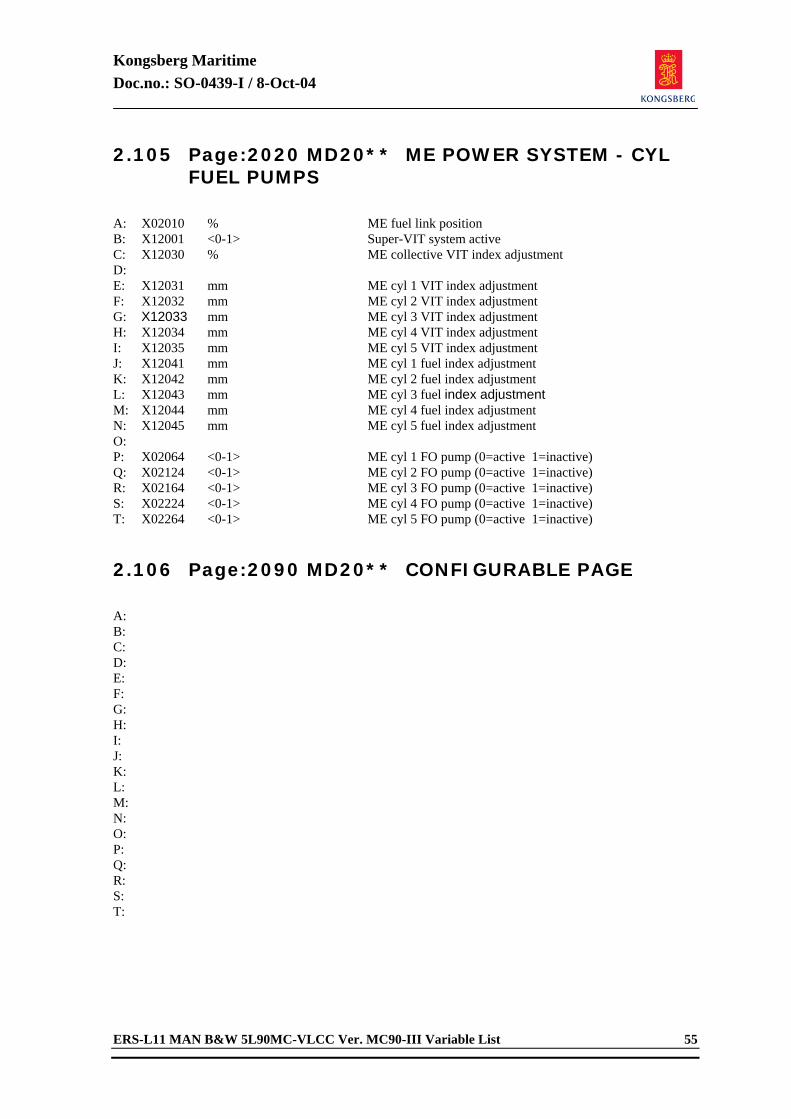
Kongsberg Maritime Doc.no.: SO-0439-I / 8-Oct-04
ERS-L11 MAN B&W 5L90MC-VLCC Ver. MC90-III Variable List 55
2.105 Page:2020 MD20** ME POWER SYSTEM - CYL FUEL PUMPS
A: X02010 % ME fuel link position B: X12001 <0-1> Super-VIT system active C: X12030 % ME collective VIT index adjustment D: E: X12031 mm ME cyl 1 VIT index adjustment F: X12032 mm ME cyl 2 VIT index adjustment G: X12033 mm ME cyl 3 VIT index adjustment H: X12034 mm ME cyl 4 VIT index adjustment I: X12035 mm ME cyl 5 VIT index adjustment J: X12041 mm ME cyl 1 fuel index adjustment K: X12042 mm ME cyl 2 fuel index adjustment L: X12043 mm ME cyl 3 fuel index adjustment M: X12044 mm ME cyl 4 fuel index adjustment N: X12045 mm ME cyl 5 fuel index adjustment O: P: X02064 <0-1> ME cyl 1 FO pump (0=active 1=inactive) Q: X02124 <0-1> ME cyl 2 FO pump (0=active 1=inactive) R: X02164 <0-1> ME cyl 3 FO pump (0=active 1=inactive) S: X02224 <0-1> ME cyl 4 FO pump (0=active 1=inactive) T: X02264 <0-1> ME cyl 5 FO pump (0=active 1=inactive) 2.106 Page:2090 MD20** CONFIGURABLE PAGE
A: B: C: D: E: F: G: H: I: J: K: L: M: N: O: P: Q: R: S: T:
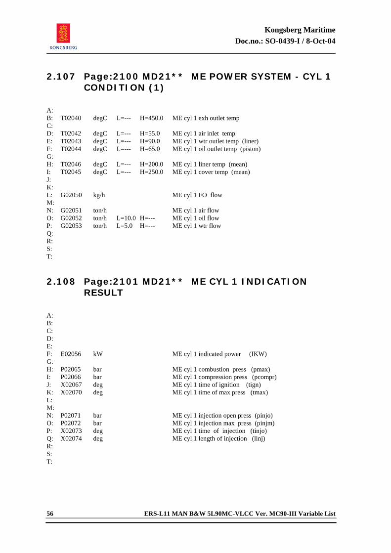
Kongsberg Maritime Doc.no.: SO-0439-I / 8-Oct-04
56 ERS-L11 MAN B&W 5L90MC-VLCC Ver. MC90-III Variable List
2.107 Page:2100 MD21** ME POWER SYSTEM - CYL 1 CONDITION (1)
A: B: T02040 degC L=--- H=450.0 ME cyl 1 exh outlet temp C: D: T02042 degC L=--- H=55.0 ME cyl 1 air inlet temp E: T02043 degC L=--- H=90.0 ME cyl 1 wtr outlet temp (liner) F: T02044 degC L=--- H=65.0 ME cyl 1 oil outlet temp (piston) G: H: T02046 degC L=--- H=200.0 ME cyl 1 liner temp (mean) I: T02045 degC L=--- H=250.0 ME cyl 1 cover temp (mean) J: K: L: G02050 kg/h ME cyl 1 FO flow M: N: G02051 ton/h ME cyl 1 air flow O: G02052 ton/h L=10.0 H=--- ME cyl 1 oil flow P: G02053 ton/h L=5.0 H=--- ME cyl 1 wtr flow Q: R: S: T: 2.108 Page:2101 MD21** ME CYL 1 INDICATION
RESULT
A: B: C: D: E: F: E02056 kW ME cyl 1 indicated power (IKW) G: H: P02065 bar ME cyl 1 combustion press (pmax) I: P02066 bar ME cyl 1 compression press (pcompr) J: X02067 deg ME cyl 1 time of ignition (tign) K: X02070 deg ME cyl 1 time of max press (tmax) L: M: N: P02071 bar ME cyl 1 injection open press (pinjo) O: P02072 bar ME cyl 1 injection max press (pinjm) P: X02073 deg ME cyl 1 time of injection (tinjo) Q: X02074 deg ME cyl 1 length of injection (linj) R: S: T:
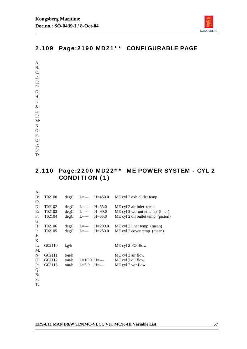
Kongsberg Maritime Doc.no.: SO-0439-I / 8-Oct-04
ERS-L11 MAN B&W 5L90MC-VLCC Ver. MC90-III Variable List 57
2.109 Page:2190 MD21** CONFIGURABLE PAGE
A: B: C: D: E: F: G: H: I: J: K: L: M: N: O: P: Q: R: S: T: 2.110 Page:2200 MD22** ME POWER SYSTEM - CYL 2
CONDITION (1)
A: B: T02100 degC L=--- H=450.0 ME cyl 2 exh outlet temp C: D: T02102 degC L=--- H=55.0 ME cyl 2 air inlet temp E: T02103 degC L=--- H=90.0 ME cyl 2 wtr outlet temp (liner) F: T02104 degC L=--- H=65.0 ME cyl 2 oil outlet temp (piston) G: H: T02106 degC L=--- H=200.0 ME cyl 2 liner temp (mean) I: T02105 degC L=--- H=250.0 ME cyl 2 cover temp (mean) J: K: L: G02110 kg/h ME cyl 2 FO flow M: N: G02111 ton/h ME cyl 2 air flow O: G02112 ton/h L=10.0 H=--- ME cyl 2 oil flow P: G02113 ton/h L=5.0 H=--- ME cyl 2 wtr flow Q: R: S: T:
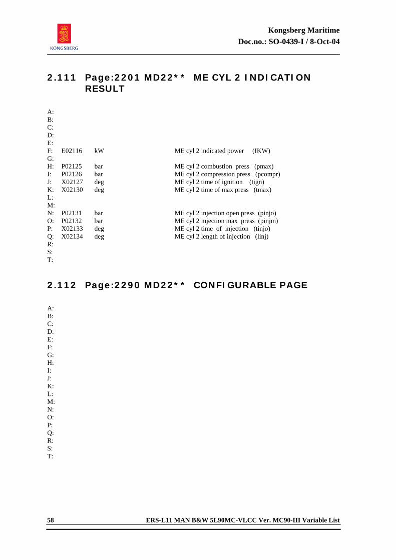
Kongsberg Maritime Doc.no.: SO-0439-I / 8-Oct-04
58 ERS-L11 MAN B&W 5L90MC-VLCC Ver. MC90-III Variable List
2.111 Page:2201 MD22** ME CYL 2 INDICATION RESULT
A: B: C: D: E: F: E02116 kW ME cyl 2 indicated power (IKW) G: H: P02125 bar ME cyl 2 combustion press (pmax) I: P02126 bar ME cyl 2 compression press (pcompr) J: X02127 deg ME cyl 2 time of ignition (tign) K: X02130 deg ME cyl 2 time of max press (tmax) L: M: N: P02131 bar ME cyl 2 injection open press (pinjo) O: P02132 bar ME cyl 2 injection max press (pinjm) P: X02133 deg ME cyl 2 time of injection (tinjo) Q: X02134 deg ME cyl 2 length of injection (linj) R: S: T: 2.112 Page:2290 MD22** CONFIGURABLE PAGE
A: B: C: D: E: F: G: H: I: J: K: L: M: N: O: P: Q: R: S: T:
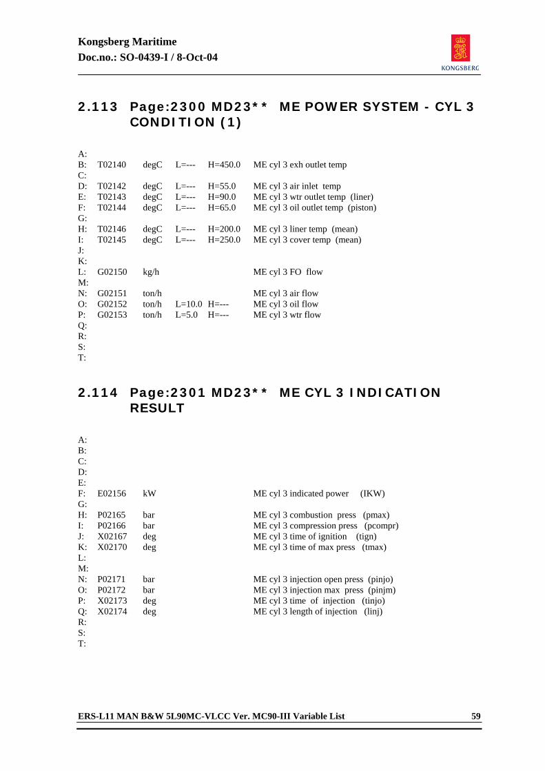
Kongsberg Maritime Doc.no.: SO-0439-I / 8-Oct-04
ERS-L11 MAN B&W 5L90MC-VLCC Ver. MC90-III Variable List 59
2.113 Page:2300 MD23** ME POWER SYSTEM - CYL 3 CONDITION (1)
A: B: T02140 degC L=--- H=450.0 ME cyl 3 exh outlet temp C: D: T02142 degC L=--- H=55.0 ME cyl 3 air inlet temp E: T02143 degC L=--- H=90.0 ME cyl 3 wtr outlet temp (liner) F: T02144 degC L=--- H=65.0 ME cyl 3 oil outlet temp (piston) G: H: T02146 degC L=--- H=200.0 ME cyl 3 liner temp (mean) I: T02145 degC L=--- H=250.0 ME cyl 3 cover temp (mean) J: K: L: G02150 kg/h ME cyl 3 FO flow M: N: G02151 ton/h ME cyl 3 air flow O: G02152 ton/h L=10.0 H=--- ME cyl 3 oil flow P: G02153 ton/h L=5.0 H=--- ME cyl 3 wtr flow Q: R: S: T: 2.114 Page:2301 MD23** ME CYL 3 INDICATION
RESULT
A: B: C: D: E: F: E02156 kW ME cyl 3 indicated power (IKW) G: H: P02165 bar ME cyl 3 combustion press (pmax) I: P02166 bar ME cyl 3 compression press (pcompr) J: X02167 deg ME cyl 3 time of ignition (tign) K: X02170 deg ME cyl 3 time of max press (tmax) L: M: N: P02171 bar ME cyl 3 injection open press (pinjo) O: P02172 bar ME cyl 3 injection max press (pinjm) P: X02173 deg ME cyl 3 time of injection (tinjo) Q: X02174 deg ME cyl 3 length of injection (linj) R: S: T:
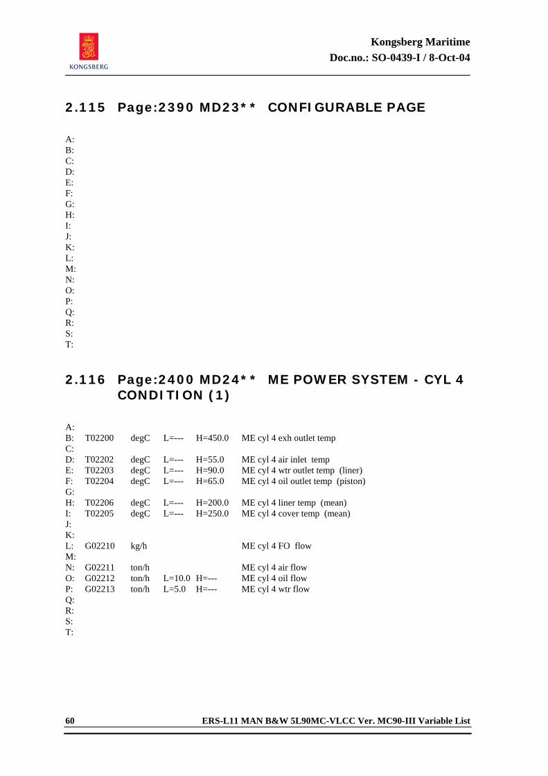
Kongsberg Maritime Doc.no.: SO-0439-I / 8-Oct-04
60 ERS-L11 MAN B&W 5L90MC-VLCC Ver. MC90-III Variable List
2.115 Page:2390 MD23** CONFIGURABLE PAGE
A: B: C: D: E: F: G: H: I: J: K: L: M: N: O: P: Q: R: S: T: 2.116 Page:2400 MD24** ME POWER SYSTEM - CYL 4
CONDITION (1)
A: B: T02200 degC L=--- H=450.0 ME cyl 4 exh outlet temp C: D: T02202 degC L=--- H=55.0 ME cyl 4 air inlet temp E: T02203 degC L=--- H=90.0 ME cyl 4 wtr outlet temp (liner) F: T02204 degC L=--- H=65.0 ME cyl 4 oil outlet temp (piston) G: H: T02206 degC L=--- H=200.0 ME cyl 4 liner temp (mean) I: T02205 degC L=--- H=250.0 ME cyl 4 cover temp (mean) J: K: L: G02210 kg/h ME cyl 4 FO flow M: N: G02211 ton/h ME cyl 4 air flow O: G02212 ton/h L=10.0 H=--- ME cyl 4 oil flow P: G02213 ton/h L=5.0 H=--- ME cyl 4 wtr flow Q: R: S: T:
Kongsberg Maritime Doc.no.: SO-0439-I / 8-Oct-04
ERS-L11 MAN B&W 5L90MC-VLCC Ver. MC90-III Variable List 61
2.117 Page:2401 MD24** ME CYL 4 INDICATION RESULT
A: B: C: D: E: F: E02216 kW ME cyl 4 indicated power (IKW) G: H: P02225 bar ME cyl 4 combustion press (pmax) I: P02226 bar ME cyl 4 compression press (pcompr) J: X02227 deg ME cyl 4 time of ignition (tign) K: X02230 deg ME cyl 4 time of max press (tmax) L: M: N: P02231 bar ME cyl 4 injection open press (pinjo) O: P02232 bar ME cyl 4 injection max press (pinjm) P: X02233 deg ME cyl 4 time of injection (tinjo) Q: X02234 deg ME cyl 4 length of injection (linj) R: S: T: 2.118 Page:2490 MD24** CONFIGURABLE PAGE
A: B: C: D: E: F: G: H: I: J: K: L: M: N: O: P: Q: R: S: T:
Kongsberg Maritime Doc.no.: SO-0439-I / 8-Oct-04
62 ERS-L11 MAN B&W 5L90MC-VLCC Ver. MC90-III Variable List
2.119 Page:2500 MD25** ME POWER SYSTEM - CYL 5 CONDITION (1)
A: B: T02240 degC L=--- H=450.0 ME cyl 5 exh outlet temp C: D: T02242 degC L=--- H=55.0 ME cyl 5 air inlet temp E: T02243 degC L=--- H=90.0 ME cyl 5 wtr outlet temp (liner) F: T02244 degC L=--- H=65.0 ME cyl 5 oil outlet temp (piston) G: H: T02246 degC L=--- H=200.0 ME cyl 5 liner temp (mean) I: T02245 degC L=--- H=250.0 ME cyl 5 cover temp (mean) J: K: L: G02250 kg/h ME cyl 5 FO flow M: N: G02251 ton/h ME cyl 5 air flow O: G02252 ton/h L=10.0 H=--- ME cyl 5 oil flow P: G02253 ton/h L=5.0 H=--- ME cyl 5 wtr flow Q: R: S: T: 2.120 Page:2501 MD25** ME CYL 5 INDICATION
RESULT
A: B: C: D: E: F: E02256 kW ME cyl 5 indicated power (IKW) G: H: P02265 bar ME cyl 5 combustion press (pmax) I: P02266 bar ME cyl 5 compression press (pcompr) J: X02267 deg ME cyl 5 time of ignition (tign) K: X02270 deg ME cyl 5 time of max press (tmax) L: M: N: P02271 bar ME cyl 5 injection open press (pinjo) O: P02272 bar ME cyl 5 injection max press (pinjm) P: X02273 deg ME cyl 5 time of injection (tinjo) Q: X02274 deg ME cyl 5 length of injection (linj) R: S: T:
Kongsberg Maritime Doc.no.: SO-0439-I / 8-Oct-04
ERS-L11 MAN B&W 5L90MC-VLCC Ver. MC90-III Variable List 63
2.121 Page:2590 MD25** CONFIGURABLE PAGE
A: B: C: D: E: F: G: H: I: J: K: L: M: N: O: P: Q: R: S: T: 2.122 Page:2700 MD27** ME PISTON RING MONITOR
(1/2)
A: B: C: D: X17100 <0-5> ME cylinder display selector E: F: X17001 % ME cyl piston ring 1 sealing G: X17002 % ME cyl piston ring 2 sealing H: X17003 % ME cyl piston ring 3 sealing I: X17004 % ME cyl piston ring 4 sealing J: K: N17001 % ME cyl piston ring 1 movement L: N17002 % ME cyl piston ring 2 movement M: N17003 % ME cyl piston ring 3 movement N: N17004 % ME cyl piston ring 4 movement O: P: T17001 degC ME cyl exhaust temperature Q: T17002 degC ME cyl cover metal temp (mean) R: T17003 degC ME cyl liner metal temp (mean) S: T:
Kongsberg Maritime Doc.no.: SO-0439-I / 8-Oct-04
64 ERS-L11 MAN B&W 5L90MC-VLCC Ver. MC90-III Variable List
2.123 Page:2701 MD27** ME PISTON RING MONITOR (2/2)
A: B: C: X17000 <0-1> ME piston ring auto wear D: C17000 <0-60> ME piston ring wear time factor E: F: G: C17001 % ME piston ring wear high (blowby start) H: C17002 % ME piston ring movement high (no wear) I: C17003 % ME piston ring movement low (alarm) J: K: C17005 % ME piston ring seal limit 1 (yellow) L: C17006 % ME piston ring seal limit 2 (red) M: N: O: P: Q: R: S: T: 2.124 Page:2790 MD27** CONFIGURABLE PAGE
A: B: C: D: E: F: G: H: I: J: K: L: M: N: O: P: Q: R: S: T:
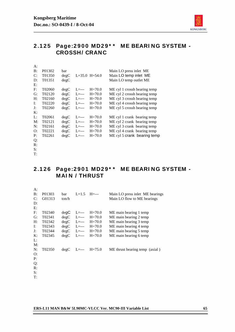
Kongsberg Maritime Doc.no.: SO-0439-I / 8-Oct-04
ERS-L11 MAN B&W 5L90MC-VLCC Ver. MC90-III Variable List 65
2.125 Page:2900 MD29** ME BEARING SYSTEM - CROSSH/CRANC
A: B: P01302 bar Main LO press inlet ME C: T01350 degC L=35.0 H=54.0 Main LO temp inlet ME D: T01351 degC Main LO temp outlet ME E: F: T02060 degC L=--- H=70.0 ME cyl 1 crossh bearing temp G: T02120 degC L=--- H=70.0 ME cyl 2 crossh bearing temp H: T02160 degC L=--- H=70.0 ME cyl 3 crossh bearing temp I: T02220 degC L=--- H=70.0 ME cyl 4 crossh bearing temp J: T02260 degC L=--- H=70.0 ME cyl 5 crossh bearing temp K: L: T02061 degC L=--- H=70.0 ME cyl 1 crank bearing temp M: T02121 degC L=--- H=70.0 ME cyl 2 crank bearing temp N: T02161 degC L=--- H=70.0 ME cyl 3 crank bearing temp O: T02221 degC L=--- H=70.0 ME cyl 4 crank bearing temp P: T02261 degC L=--- H=70.0 ME cyl 5 crank bearing temp Q: R: S: T: 2.126 Page:2901 MD29** ME BEARING SYSTEM -
MAIN /THRUST
A: B: P01303 bar L=1.5 H=--- Main LO press inlet ME bearings C: G01313 ton/h Main LO flow to ME bearings D: E: F: T02340 degC L=--- H=70.0 ME main bearing 1 temp G: T02341 degC L=--- H=70.0 ME main bearing 2 temp H: T02342 degC L=--- H=70.0 ME main bearing 3 temp I: T02343 degC L=--- H=70.0 ME main bearing 4 temp J: T02344 degC L=--- H=70.0 ME main bearing 5 temp K: T02345 degC L=--- H=70.0 ME main bearing 6 temp L: M: N: T02350 degC L=--- H=75.0 ME thrust bearing temp (axial ) O: P: Q: R: S: T:
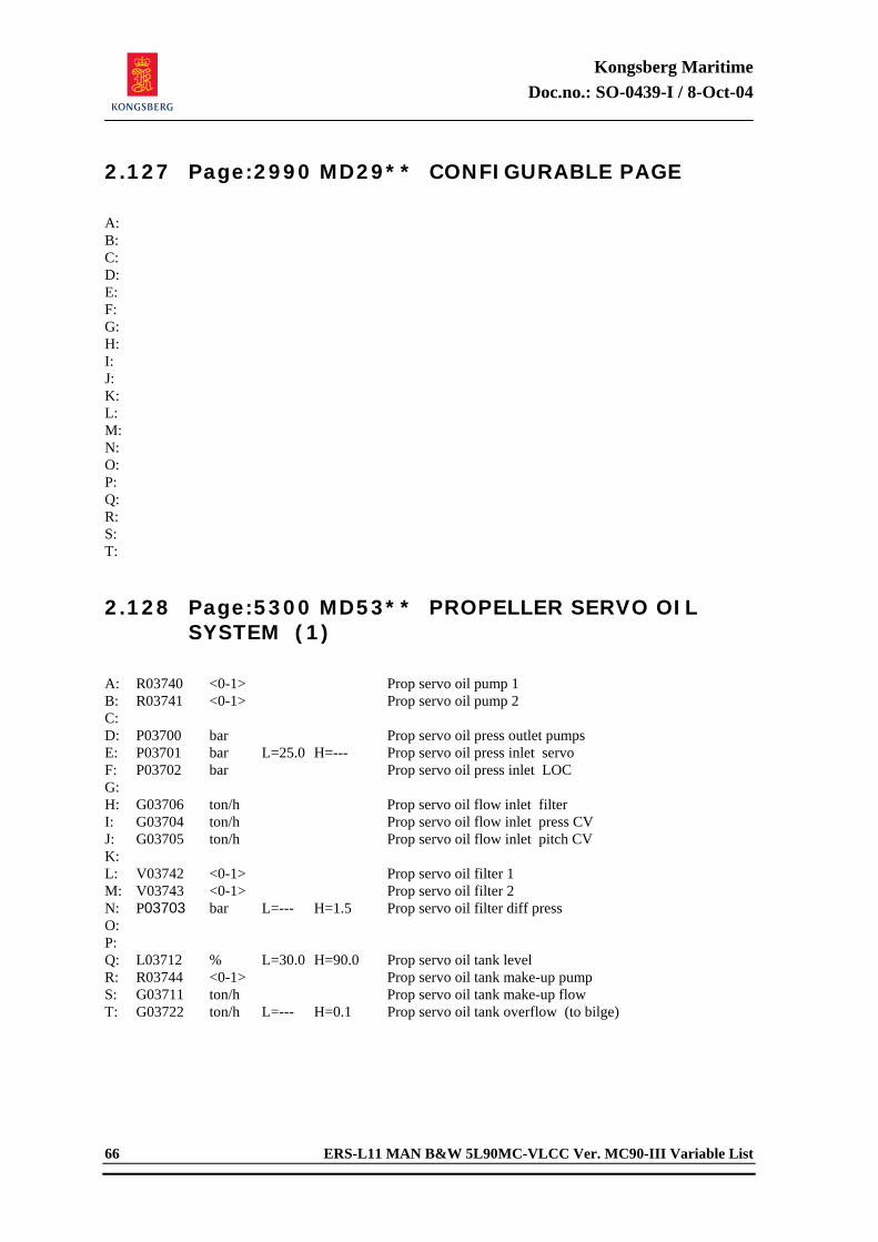
Kongsberg Maritime Doc.no.: SO-0439-I / 8-Oct-04
66 ERS-L11 MAN B&W 5L90MC-VLCC Ver. MC90-III Variable List
2.127 Page:2990 MD29** CONFIGURABLE PAGE
A: B: C: D: E: F: G: H: I: J: K: L: M: N: O: P: Q: R: S: T: 2.128 Page:5300 MD53** PROPELLER SERVO OIL
SYSTEM (1)
A: R03740 <0-1> Prop servo oil pump 1 B: R03741 <0-1> Prop servo oil pump 2 C: D: P03700 bar Prop servo oil press outlet pumps E: P03701 bar L=25.0 H=--- Prop servo oil press inlet servo F: P03702 bar Prop servo oil press inlet LOC G: H: G03706 ton/h Prop servo oil flow inlet filter I: G03704 ton/h Prop servo oil flow inlet press CV J: G03705 ton/h Prop servo oil flow inlet pitch CV K: L: V03742 <0-1> Prop servo oil filter 1 M: V03743 <0-1> Prop servo oil filter 2 N: P03703 bar L=--- H=1.5 Prop servo oil filter diff press O: P: Q: L03712 % L=30.0 H=90.0 Prop servo oil tank level R: R03744 <0-1> Prop servo oil tank make-up pump S: G03711 ton/h Prop servo oil tank make-up flow T: G03722 ton/h L=--- H=0.1 Prop servo oil tank overflow (to bilge)

Kongsberg Maritime Doc.no.: SO-0439-I / 8-Oct-04
ERS-L11 MAN B&W 5L90MC-VLCC Ver. MC90-III Variable List 67
2.129 Page:5301 MD53** PROPELLER SERVO OIL SYSTEM (2)
A: B: T03713 degC L=--- H=50.0 Prop servo oil tank temp C: T03734 degC Prop servo oil temp inlet LOC D: T03721 degC Prop servo oil temp outlet LOC E: F: T03715 degC Prop servo oil temp contr set point G: V03714 % Prop servo oil temp contr valve pos H: C03716 %/degC Prop servo oil temp contr gain I: C03717 % Prop servo oil temp contr bias J: K: G03707 ton/h Prop servo oil flow inlet LOC L: G03710 ton/h Prop servo oil flow bypass LOC M: N: O: P: V03733 <0-1> Prop servo CW flow shut off valve Q: G03730 ton/h Prop servo CW flow outlet LOC R: S: T03731 degC Prop servo CW temp inlet LOC T: T03732 degC Prop servo CW temp outlet LOC 2.130 Page:5302 MD53** PROPELLER SERVO OIL
SYSTEM (3)
A: B: C: D: P03701 bar L=25.0 H=--- Prop servo oil press inlet servo E: F: G: P03725 bar Prop servo oil press contr set point H: V03724 % Prop servo oil press contr valve pos I: J: C03726 %/bar Prop servo oil press contr gain K: C03727 % Prop servo oil press contr bias L: M: N: O: P: Q: R: S: T:
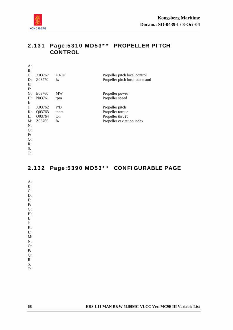
Kongsberg Maritime Doc.no.: SO-0439-I / 8-Oct-04
68 ERS-L11 MAN B&W 5L90MC-VLCC Ver. MC90-III Variable List
2.131 Page:5310 MD53** PROPELLER PITCH CONTROL
A: B: C: X03767 <0-1> Propeller pitch local control D: Z03770 % Propeller pitch local command E: F: G: E03760 MW Propeller power H: N03761 rpm Propeller speed I: J: X03762 P/D Propeller pitch K: Q03763 tonm Propeller torque L: Q03764 ton Propeller thrust M: Z03765 % Propeller cavitation index N: O: P: Q: R: S: T: 2.132 Page:5390 MD53** CONFIGURABLE PAGE
A: B: C: D: E: F: G: H: I: J: K: L: M: N: O: P: Q: R: S: T:
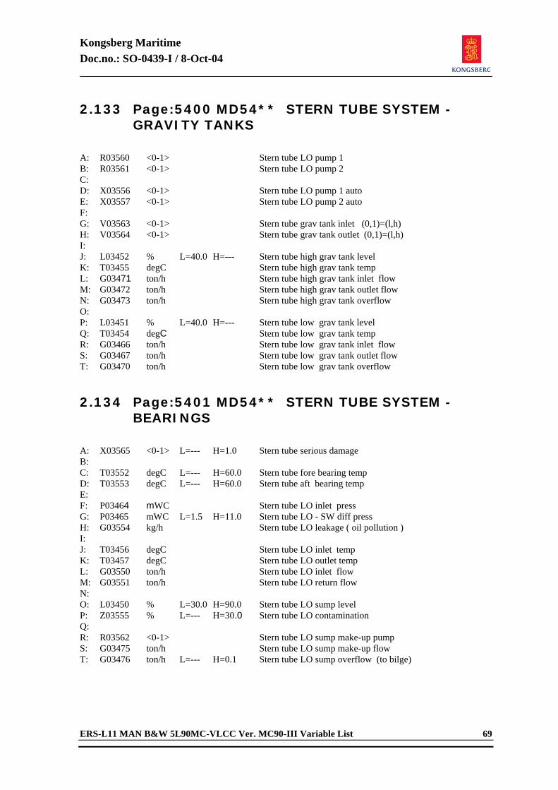
Kongsberg Maritime Doc.no.: SO-0439-I / 8-Oct-04
ERS-L11 MAN B&W 5L90MC-VLCC Ver. MC90-III Variable List 69
2.133 Page:5400 MD54** STERN TUBE SYSTEM - GRAVITY TANKS
A: R03560 <0-1> Stern tube LO pump 1 B: R03561 <0-1> Stern tube LO pump 2 C: D: X03556 <0-1> Stern tube LO pump 1 auto E: X03557 <0-1> Stern tube LO pump 2 auto F: G: V03563 <0-1> Stern tube grav tank inlet (0,1)=(l,h) H: V03564 <0-1> Stern tube grav tank outlet (0,1)=(l,h) I: J: L03452 % L=40.0 H=--- Stern tube high grav tank level K: T03455 degC Stern tube high grav tank temp L: G03471 ton/h Stern tube high grav tank inlet flow M: G03472 ton/h Stern tube high grav tank outlet flow N: G03473 ton/h Stern tube high grav tank overflow O: P: L03451 % L=40.0 H=--- Stern tube low grav tank level Q: T03454 degC Stern tube low grav tank temp R: G03466 ton/h Stern tube low grav tank inlet flow S: G03467 ton/h Stern tube low grav tank outlet flow T: G03470 ton/h Stern tube low grav tank overflow 2.134 Page:5401 MD54** STERN TUBE SYSTEM -
BEARINGS
A: X03565 <0-1> L=--- H=1.0 Stern tube serious damage B: C: T03552 degC L=--- H=60.0 Stern tube fore bearing temp D: T03553 degC L=--- H=60.0 Stern tube aft bearing temp E: F: P03464 mWC Stern tube LO inlet press G: P03465 mWC L=1.5 H=11.0 Stern tube LO - SW diff press H: G03554 kg/h Stern tube LO leakage ( oil pollution ) I: J: T03456 degC Stern tube LO inlet temp K: T03457 degC Stern tube LO outlet temp L: G03550 ton/h Stern tube LO inlet flow M: G03551 ton/h Stern tube LO return flow N: O: L03450 % L=30.0 H=90.0 Stern tube LO sump level P: Z03555 % L=--- H=30.0 Stern tube LO contamination Q: R: R03562 <0-1> Stern tube LO sump make-up pump S: G03475 ton/h Stern tube LO sump make-up flow T: G03476 ton/h L=--- H=0.1 Stern tube LO sump overflow (to bilge)
Kongsberg Maritime Doc.no.: SO-0439-I / 8-Oct-04
70 ERS-L11 MAN B&W 5L90MC-VLCC Ver. MC90-III Variable List
2.135 Page:5402 MD54** STERN TUBE SYSTEM - LO COOLER
A: B: T03453 degC L=--- H=60.0 Stern tube LO sump temp C: D: P03463 bar Stern tube LOC LO inlet press E: P03462 bar Stern tube LOC LO outlet press F: G: G03477 ton/h Stern tube LOC LO inlet flow H: T03460 degC Stern tube LOC LO outlet temp I: J: V03571 <0-1> Stern tube LOC CW inlet valve K: G03570 ton/h Stern tube LOC CW inlet flow L: T03461 degC Stern tube LOC CW outlet temp M: N: O: V03572 <0-1> Stern tube LO discharge valve P: G03474 ton/h Stern tube LO discharge flow (to spill) Q: R: S: T: C03566 degC Stern tube serious damage limit 2.136 Page:5490 MD54** CONFIGURABLE PAGE
A: B: C: D: E: F: G: H: I: J: K: L: M: N: O: P: Q: R: S: T:
Kongsberg Maritime Doc.no.: SO-0439-I / 8-Oct-04
ERS-L11 MAN B&W 5L90MC-VLCC Ver. MC90-III Variable List 71
2.137 Page:5600 MD56** SHIP PROPULSION SYSTEM - HULL FORCES
A: N06312 knot Ship speed B: X06314 nm Ship pos C: D: G06326 kg/h Total ME FO flow E: G06327 kg/h Total DG FO flow (net) F: G: X06334 % Ship load ( active ) H: X06335 m Trim ( active ) I: X06336 deg Heel ( active ) J: K: X03771 <0-1> Propeller type (0=small,1=big) L: M: N03761 rpm Propeller speed N: E03760 MW Propeller power O: Z03766 % Propeller efficiency P: Q03764 ton Propeller thrust Q: Q06331 ton Ship hull drag force (total) R: S: E06325 kg/Nm Overall propulsion efficiency T: 2.138 Page:5601 MD56** SHIP PROPULSION SYSTEM
- STEERING GEAR
A: B: R06276 <0-1> Steering gear servo pump 1 C: R06277 <0-1> Steering gear servo pump 2 D: E: F: G: H: I: J: K: L: R06270 <0-1> Bow thruster run (start/stop) M: X06278 P/D Bow thruster pitch N: O: E06272 kW Bow thruster power P: Q06273 ton Bow thruster force (lateral) Q: I06279 A Bow thruster current R: S: T:
Kongsberg Maritime Doc.no.: SO-0439-I / 8-Oct-04
72 ERS-L11 MAN B&W 5L90MC-VLCC Ver. MC90-III Variable List
2.139 Page:5610 MD56** SHIP COURSE CONTROL (1)
A: B: N06313 knot Ship speed (manual if isola) C: X06314 nm Ship pos D: E: X06300 <0-2> Auto pilot F: G: X06306 deg Ship course command H: X06307 deg Ship course (-180/180) I: X06310 deg Ship course (0-360) J: K: X06304 deg Rudder command L: X06305 deg Rudder pos M: R06311 - Turning rate (l/r) N: O: X06318 <0-1> Emergency rudder control - Stbd (local) P: X06319 <0-1> Emergency rudder control - Port (local) Q: R: C06301 - Autopilot course gain S: C06302 - Autopilot rate gain T: C06303 - Autopilot course deadband 2.140 Page:5611 MD56** SHIP COURSE CONTROL
(2)
A: B: X07041 <0-1> Ship speed isolation (autopilot) C: D: E: Q03764 ton Propeller thrust F: Q06331 ton Ship hull drag force (total) G: H: Q06332 ton Ice resistance force I: Q06333 ton Wind resistance force J: K: L: Z00770 Beauf Weather condition (waves) M: N00766 m/sec Wind force ( speed ) N: X00767 deg Wind direction (0-360 dgr) O: X06315 m Sea water depth P: Q: X06323 m Draft ( mean ) R: S: T:
Kongsberg Maritime Doc.no.: SO-0439-I / 8-Oct-04
ERS-L11 MAN B&W 5L90MC-VLCC Ver. MC90-III Variable List 73
2.141 Page:5690 MD56** CONFIGURABLE PAGE
A: B: C: D: E: F: G: H: I: J: K: L: M: N: O: P: Q: R: S: T: 2.142 Page:5700 MD57** SHIP LOAD CONDITION
(1)
A: B: M06316 kton Ship load (deadweigth) C: X06320 % Ship load (relative) D: E: F: X06321 m Trim (by stern) G: X06322 m Heel (by stbd) H: X06323 m Draft ( mean ) I: J: K: M06360 ton Spill oil tank content L: M06361 ton HFO service tank content M: M06362 ton DO service tank content N: M06363 ton HFO settl tank 1 content O: M06364 ton HFO settl tank 2 content P: Q: M06365 ton DO storage tank content R: S: M06367 ton Distilled FW tank content T:
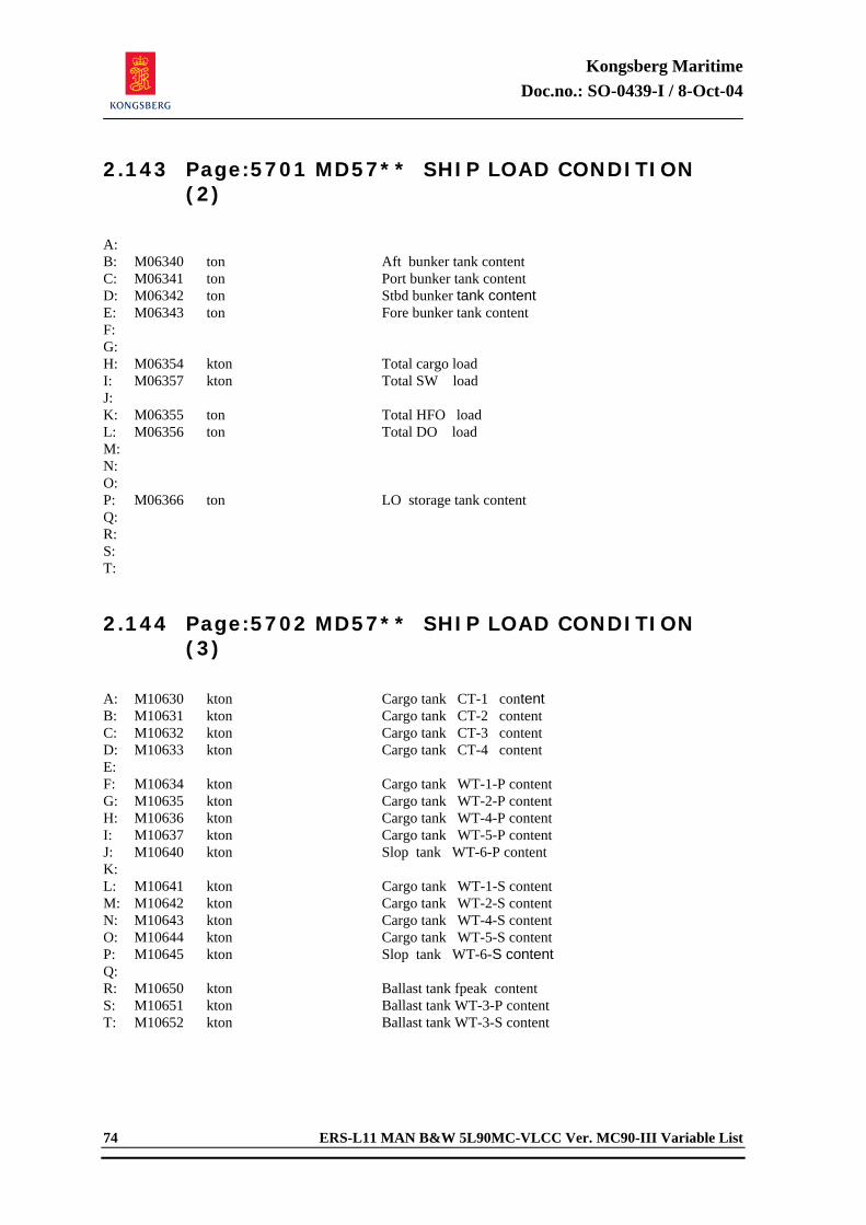
Kongsberg Maritime Doc.no.: SO-0439-I / 8-Oct-04
74 ERS-L11 MAN B&W 5L90MC-VLCC Ver. MC90-III Variable List
2.143 Page:5701 MD57** SHIP LOAD CONDITION (2)
A: B: M06340 ton Aft bunker tank content C: M06341 ton Port bunker tank content D: M06342 ton Stbd bunker tank content E: M06343 ton Fore bunker tank content F: G: H: M06354 kton Total cargo load I: M06357 kton Total SW load J: K: M06355 ton Total HFO load L: M06356 ton Total DO load M: N: O: P: M06366 ton LO storage tank content Q: R: S: T: 2.144 Page:5702 MD57** SHIP LOAD CONDITION
(3)
A: M10630 kton Cargo tank CT-1 content B: M10631 kton Cargo tank CT-2 content C: M10632 kton Cargo tank CT-3 content D: M10633 kton Cargo tank CT-4 content E: F: M10634 kton Cargo tank WT-1-P content G: M10635 kton Cargo tank WT-2-P content H: M10636 kton Cargo tank WT-4-P content I: M10637 kton Cargo tank WT-5-P content J: M10640 kton Slop tank WT-6-P content K: L: M10641 kton Cargo tank WT-1-S content M: M10642 kton Cargo tank WT-2-S content N: M10643 kton Cargo tank WT-4-S content O: M10644 kton Cargo tank WT-5-S content P: M10645 kton Slop tank WT-6-S content Q: R: M10650 kton Ballast tank fpeak content S: M10651 kton Ballast tank WT-3-P content T: M10652 kton Ballast tank WT-3-S content
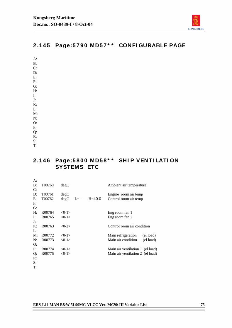
Kongsberg Maritime Doc.no.: SO-0439-I / 8-Oct-04
ERS-L11 MAN B&W 5L90MC-VLCC Ver. MC90-III Variable List 75
2.145 Page:5790 MD57** CONFIGURABLE PAGE
A: B: C: D: E: F: G: H: I: J: K: L: M: N: O: P: Q: R: S: T: 2.146 Page:5800 MD58** SHIP VENTILATION
SYSTEMS ETC
A: B: T00760 degC Ambient air temperature C: D: T00761 degC Engine room air temp E: T00762 degC L=--- H=40.0 Control room air temp F: G: H: R00764 <0-1> Eng room fan 1 I: R00765 <0-1> Eng room fan 2 J: K: R00763 <0-2> Control room air condition L: M: R00772 <0-1> Main refrigeration (el load) N: R00773 <0-1> Main air condition (el load) O: P: R00774 <0-1> Main air ventilation 1 (el load) Q: R00775 <0-1> Main air ventilation 2 (el load) R: S: T:
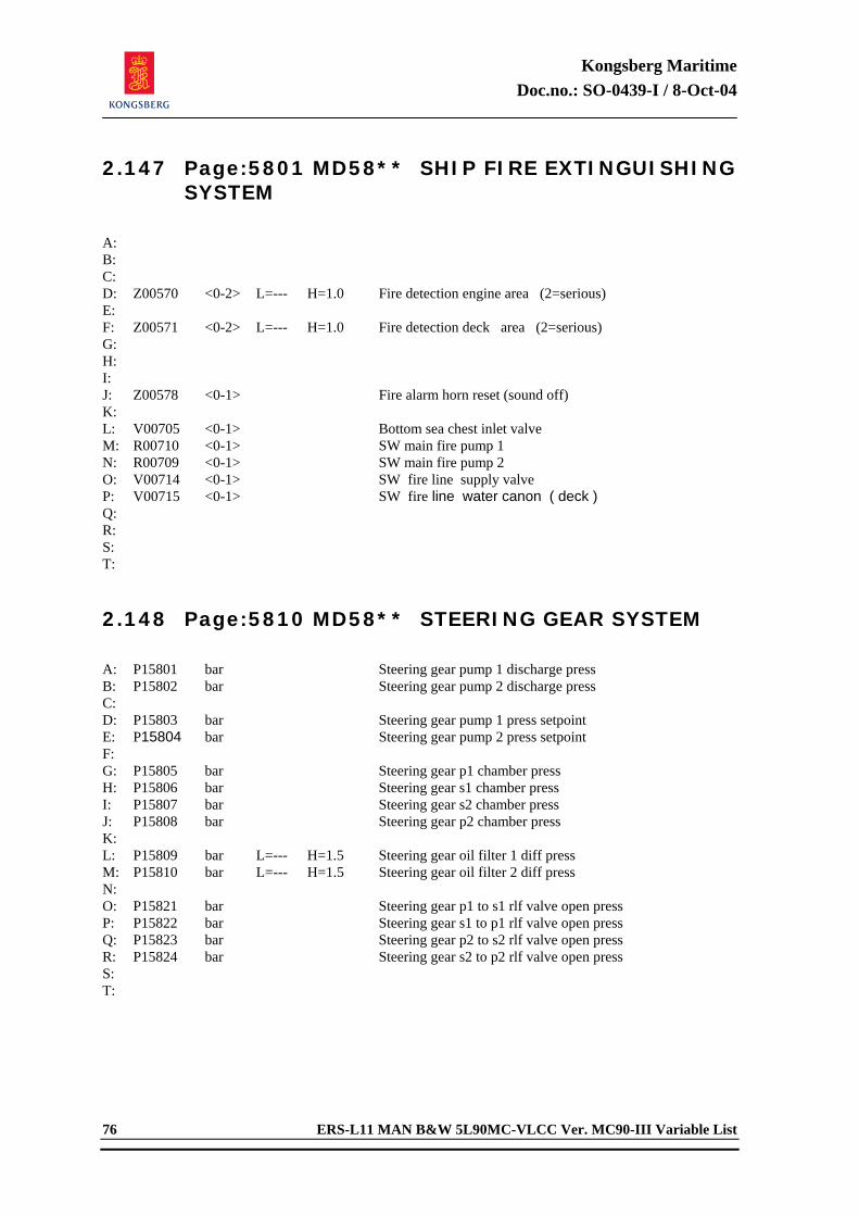
Kongsberg Maritime Doc.no.: SO-0439-I / 8-Oct-04
76 ERS-L11 MAN B&W 5L90MC-VLCC Ver. MC90-III Variable List
2.147 Page:5801 MD58** SHIP FIRE EXTINGUISHING SYSTEM
A: B: C: D: Z00570 <0-2> L=--- H=1.0 Fire detection engine area (2=serious) E: F: Z00571 <0-2> L=--- H=1.0 Fire detection deck area (2=serious) G: H: I: J: Z00578 <0-1> Fire alarm horn reset (sound off) K: L: V00705 <0-1> Bottom sea chest inlet valve M: R00710 <0-1> SW main fire pump 1 N: R00709 <0-1> SW main fire pump 2 O: V00714 <0-1> SW fire line supply valve P: V00715 <0-1> SW fire line water canon ( deck ) Q: R: S: T: 2.148 Page:5810 MD58** STEERING GEAR SYSTEM
A: P15801 bar Steering gear pump 1 discharge press B: P15802 bar Steering gear pump 2 discharge press C: D: P15803 bar Steering gear pump 1 press setpoint E: P15804 bar Steering gear pump 2 press setpoint F: G: P15805 bar Steering gear p1 chamber press H: P15806 bar Steering gear s1 chamber press I: P15807 bar Steering gear s2 chamber press J: P15808 bar Steering gear p2 chamber press K: L: P15809 bar L=--- H=1.5 Steering gear oil filter 1 diff press M: P15810 bar L=--- H=1.5 Steering gear oil filter 2 diff press N: O: P15821 bar Steering gear p1 to s1 rlf valve open press P: P15822 bar Steering gear s1 to p1 rlf valve open press Q: P15823 bar Steering gear p2 to s2 rlf valve open press R: P15824 bar Steering gear s2 to p2 rlf valve open press S: T:
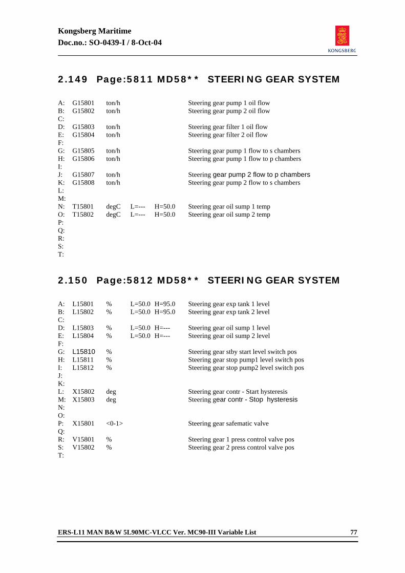
Kongsberg Maritime Doc.no.: SO-0439-I / 8-Oct-04
ERS-L11 MAN B&W 5L90MC-VLCC Ver. MC90-III Variable List 77
2.149 Page:5811 MD58** STEERING GEAR SYSTEM
A: G15801 ton/h Steering gear pump 1 oil flow B: G15802 ton/h Steering gear pump 2 oil flow C: D: G15803 ton/h Steering gear filter 1 oil flow E: G15804 ton/h Steering gear filter 2 oil flow F: G: G15805 ton/h Steering gear pump 1 flow to s chambers H: G15806 ton/h Steering gear pump 1 flow to p chambers I: J: G15807 ton/h Steering gear pump 2 flow to p chambers K: G15808 ton/h Steering gear pump 2 flow to s chambers L: M: N: T15801 degC L=--- H=50.0 Steering gear oil sump 1 temp O: T15802 degC L=--- H=50.0 Steering gear oil sump 2 temp P: Q: R: S: T: 2.150 Page:5812 MD58** STEERING GEAR SYSTEM
A: L15801 % L=50.0 H=95.0 Steering gear exp tank 1 level B: L15802 % L=50.0 H=95.0 Steering gear exp tank 2 level C: D: L15803 % L=50.0 H=--- Steering gear oil sump 1 level E: L15804 % L=50.0 H=--- Steering gear oil sump 2 level F: G: L15810 % Steering gear stby start level switch pos H: L15811 % Steering gear stop pump1 level switch pos I: L15812 % Steering gear stop pump2 level switch pos J: K: L: X15802 deg Steering gear contr - Start hysteresis M: X15803 deg Steering gear contr - Stop hysteresis N: O: P: X15801 <0-1> Steering gear safematic valve Q: R: V15801 % Steering gear 1 press control valve pos S: V15802 % Steering gear 2 press control valve pos T:
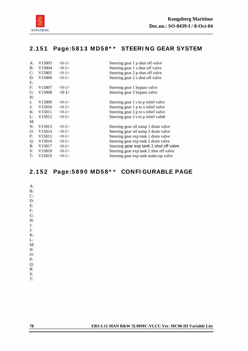
Kongsberg Maritime Doc.no.: SO-0439-I / 8-Oct-04
78 ERS-L11 MAN B&W 5L90MC-VLCC Ver. MC90-III Variable List
2.151 Page:5813 MD58** STEERING GEAR SYSTEM
A: V15803 <0-1> Steering gear 1 p shut off valve B: V15804 <0-1> Steering gear 1 s shut off valve C: V15805 <0-1> Steering gear 2 p shut off valve D: V15806 <0-1> Steering gear 2 s shut off valve E: F: V15807 <0-1> Steering gear 1 bypass valve G: V15808 <0-1> Steering gear 2 bypass valve H: I: V15809 <0-1> Steering gear 1 s to p relief valve J: V15810 <0-1> Steering gear 1 p to s relief valve K: V15811 <0-1> Steering gear 2 p to s relief valve L: V15812 <0-1> Steering gear 2 s to p relief valve M: N: V15813 <0-1> Steering gear oil sump 1 drain valve O: V15814 <0-1> Steering gear oil sump 2 drain valve P: V15815 <0-1> Steering gear exp tank 1 drain valve Q: V15816 <0-1> Steering gear exp tank 2 drain valve R: V15817 <0-1> Steering gear exp tank 1 shut off valve S: V15818 <0-1> Steering gear exp tank 2 shut off valve T: V15819 <0-1> Steering gear exp tank make-up valve 2.152 Page:5890 MD58** CONFIGURABLE PAGE
A: B: C: D: E: F: G: H: I: J: K: L: M: N: O: P: Q: R: S: T:
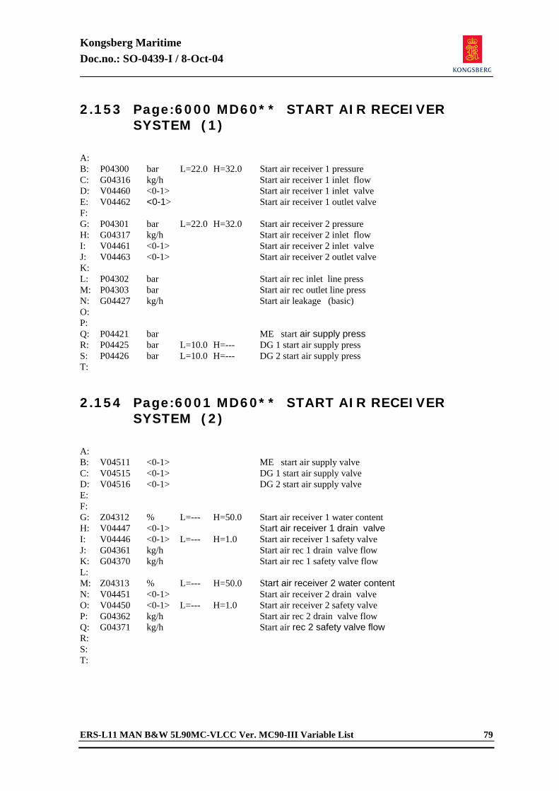
Kongsberg Maritime Doc.no.: SO-0439-I / 8-Oct-04
ERS-L11 MAN B&W 5L90MC-VLCC Ver. MC90-III Variable List 79
2.153 Page:6000 MD60** START AIR RECEIVER SYSTEM (1)
A: B: P04300 bar L=22.0 H=32.0 Start air receiver 1 pressure C: G04316 kg/h Start air receiver 1 inlet flow D: V04460 <0-1> Start air receiver 1 inlet valve E: V04462 <0-1> Start air receiver 1 outlet valve F: G: P04301 bar L=22.0 H=32.0 Start air receiver 2 pressure H: G04317 kg/h Start air receiver 2 inlet flow I: V04461 <0-1> Start air receiver 2 inlet valve J: V04463 <0-1> Start air receiver 2 outlet valve K: L: P04302 bar Start air rec inlet line press M: P04303 bar Start air rec outlet line press N: G04427 kg/h Start air leakage (basic) O: P: Q: P04421 bar ME start air supply press R: P04425 bar L=10.0 H=--- DG 1 start air supply press S: P04426 bar L=10.0 H=--- DG 2 start air supply press T: 2.154 Page:6001 MD60** START AIR RECEIVER
SYSTEM (2)
A: B: V04511 <0-1> ME start air supply valve C: V04515 <0-1> DG 1 start air supply valve D: V04516 <0-1> DG 2 start air supply valve E: F: G: Z04312 % L=--- H=50.0 Start air receiver 1 water content H: V04447 <0-1> Start air receiver 1 drain valve I: V04446 <0-1> L=--- H=1.0 Start air receiver 1 safety valve J: G04361 kg/h Start air rec 1 drain valve flow K: G04370 kg/h Start air rec 1 safety valve flow L: M: Z04313 % L=--- H=50.0 Start air receiver 2 water content N: V04451 <0-1> Start air receiver 2 drain valve O: V04450 <0-1> L=--- H=1.0 Start air receiver 2 safety valve P: G04362 kg/h Start air rec 2 drain valve flow Q: G04371 kg/h Start air rec 2 safety valve flow R: S: T:
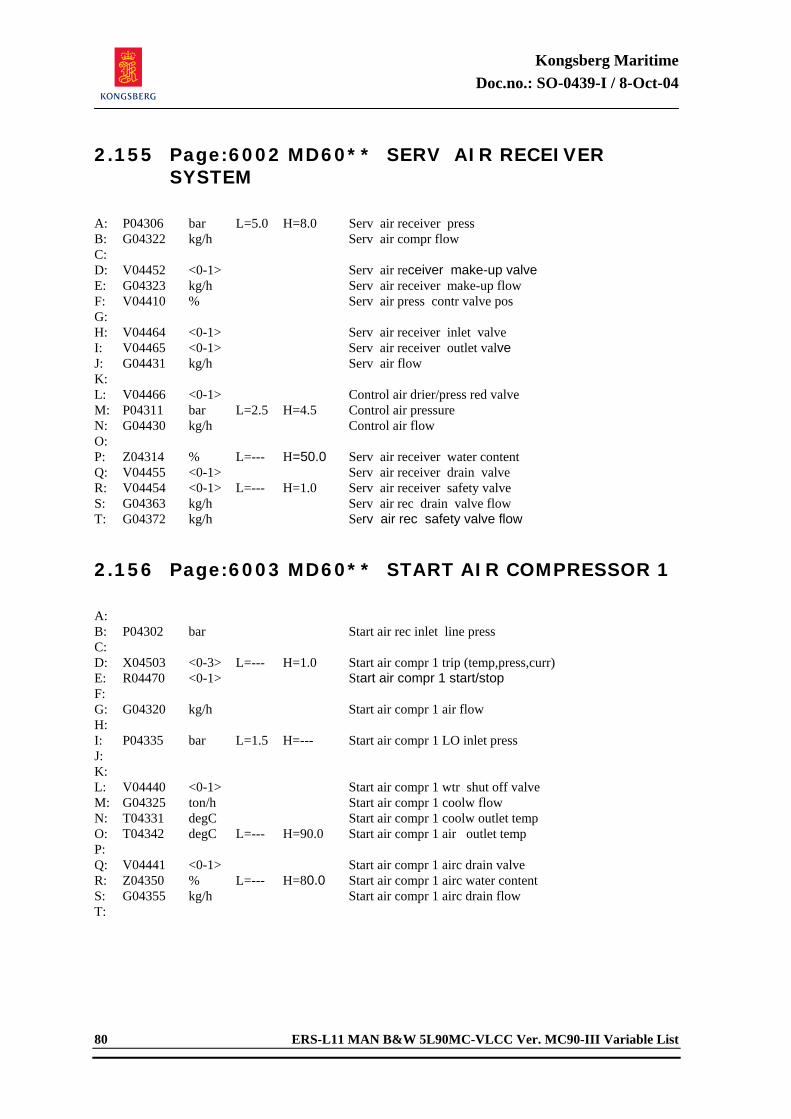
Kongsberg Maritime Doc.no.: SO-0439-I / 8-Oct-04
80 ERS-L11 MAN B&W 5L90MC-VLCC Ver. MC90-III Variable List
2.155 Page:6002 MD60** SERV AIR RECEIVER SYSTEM
A: P04306 bar L=5.0 H=8.0 Serv air receiver press B: G04322 kg/h Serv air compr flow C: D: V04452 <0-1> Serv air receiver make-up valve E: G04323 kg/h Serv air receiver make-up flow F: V04410 % Serv air press contr valve pos G: H: V04464 <0-1> Serv air receiver inlet valve I: V04465 <0-1> Serv air receiver outlet valve J: G04431 kg/h Serv air flow K: L: V04466 <0-1> Control air drier/press red valve M: P04311 bar L=2.5 H=4.5 Control air pressure N: G04430 kg/h Control air flow O: P: Z04314 % L=--- H=50.0 Serv air receiver water content Q: V04455 <0-1> Serv air receiver drain valve R: V04454 <0-1> L=--- H=1.0 Serv air receiver safety valve S: G04363 kg/h Serv air rec drain valve flow T: G04372 kg/h Serv air rec safety valve flow 2.156 Page:6003 MD60** START AIR COMPRESSOR 1
A: B: P04302 bar Start air rec inlet line press C: D: X04503 <0-3> L=--- H=1.0 Start air compr 1 trip (temp,press,curr) E: R04470 <0-1> Start air compr 1 start/stop F: G: G04320 kg/h Start air compr 1 air flow H: I: P04335 bar L=1.5 H=--- Start air compr 1 LO inlet press J: K: L: V04440 <0-1> Start air compr 1 wtr shut off valve M: G04325 ton/h Start air compr 1 coolw flow N: T04331 degC Start air compr 1 coolw outlet temp O: T04342 degC L=--- H=90.0 Start air compr 1 air outlet temp P: Q: V04441 <0-1> Start air compr 1 airc drain valve R: Z04350 % L=--- H=80.0 Start air compr 1 airc water content S: G04355 kg/h Start air compr 1 airc drain flow T:
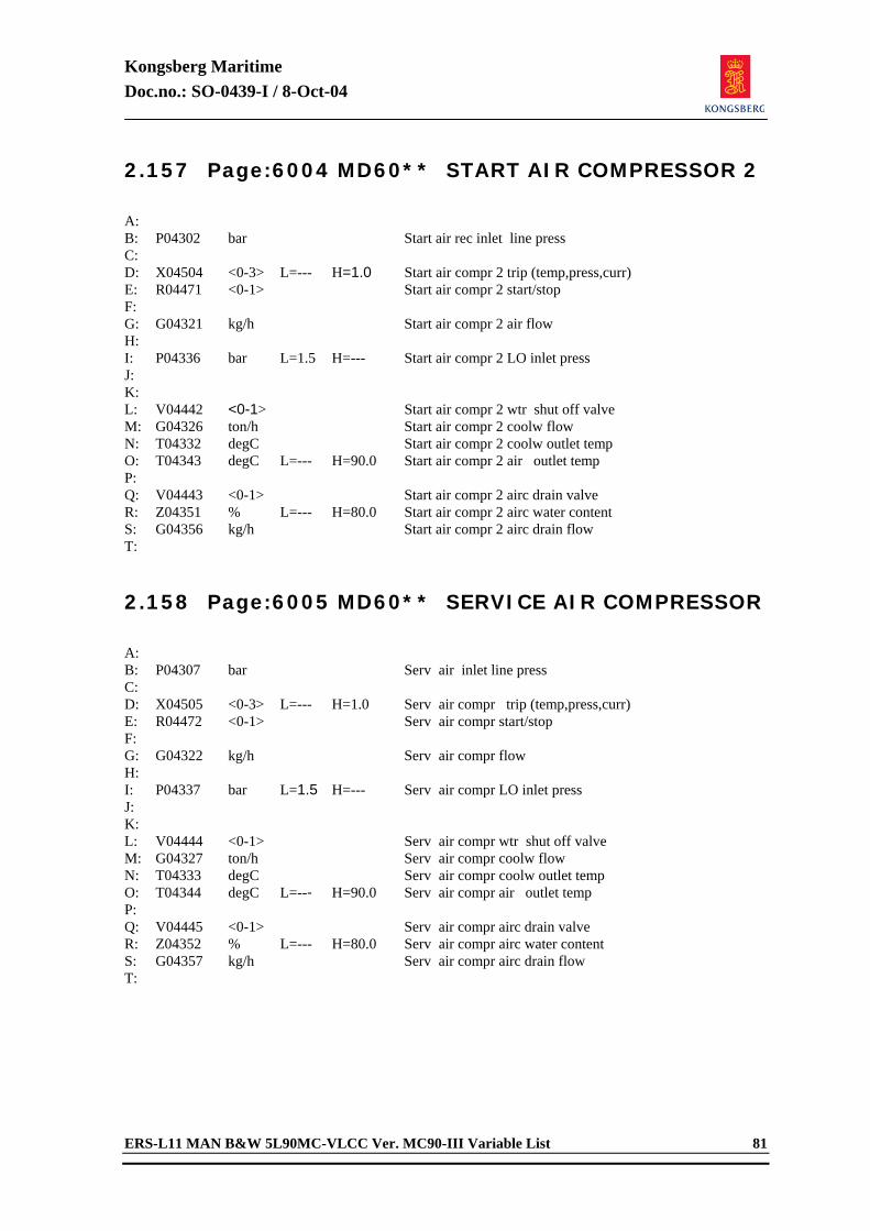
Kongsberg Maritime Doc.no.: SO-0439-I / 8-Oct-04
ERS-L11 MAN B&W 5L90MC-VLCC Ver. MC90-III Variable List 81
2.157 Page:6004 MD60** START AIR COMPRESSOR 2
A: B: P04302 bar Start air rec inlet line press C: D: X04504 <0-3> L=--- H=1.0 Start air compr 2 trip (temp,press,curr) E: R04471 <0-1> Start air compr 2 start/stop F: G: G04321 kg/h Start air compr 2 air flow H: I: P04336 bar L=1.5 H=--- Start air compr 2 LO inlet press J: K: L: V04442 <0-1> Start air compr 2 wtr shut off valve M: G04326 ton/h Start air compr 2 coolw flow N: T04332 degC Start air compr 2 coolw outlet temp O: T04343 degC L=--- H=90.0 Start air compr 2 air outlet temp P: Q: V04443 <0-1> Start air compr 2 airc drain valve R: Z04351 % L=--- H=80.0 Start air compr 2 airc water content S: G04356 kg/h Start air compr 2 airc drain flow T: 2.158 Page:6005 MD60** SERVICE AIR COMPRESSOR
A: B: P04307 bar Serv air inlet line press C: D: X04505 <0-3> L=--- H=1.0 Serv air compr trip (temp,press,curr) E: R04472 <0-1> Serv air compr start/stop F: G: G04322 kg/h Serv air compr flow H: I: P04337 bar L=1.5 H=--- Serv air compr LO inlet press J: K: L: V04444 <0-1> Serv air compr wtr shut off valve M: G04327 ton/h Serv air compr coolw flow N: T04333 degC Serv air compr coolw outlet temp O: T04344 degC L=--- H=90.0 Serv air compr air outlet temp P: Q: V04445 <0-1> Serv air compr airc drain valve R: Z04352 % L=--- H=80.0 Serv air compr airc water content S: G04357 kg/h Serv air compr airc drain flow T:
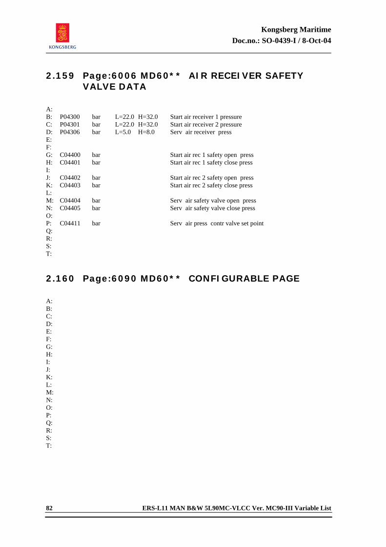
Kongsberg Maritime Doc.no.: SO-0439-I / 8-Oct-04
82 ERS-L11 MAN B&W 5L90MC-VLCC Ver. MC90-III Variable List
2.159 Page:6006 MD60** AIR RECEIVER SAFETY VALVE DATA
A: B: P04300 bar L=22.0 H=32.0 Start air receiver 1 pressure C: P04301 bar L=22.0 H=32.0 Start air receiver 2 pressure D: P04306 bar L=5.0 H=8.0 Serv air receiver press E: F: G: C04400 bar Start air rec 1 safety open press H: C04401 bar Start air rec 1 safety close press I: J: C04402 bar Start air rec 2 safety open press K: C04403 bar Start air rec 2 safety close press L: M: C04404 bar Serv air safety valve open press N: C04405 bar Serv air safety valve close press O: P: C04411 bar Serv air press contr valve set point Q: R: S: T: 2.160 Page:6090 MD60** CONFIGURABLE PAGE
A: B: C: D: E: F: G: H: I: J: K: L: M: N: O: P: Q: R: S: T:
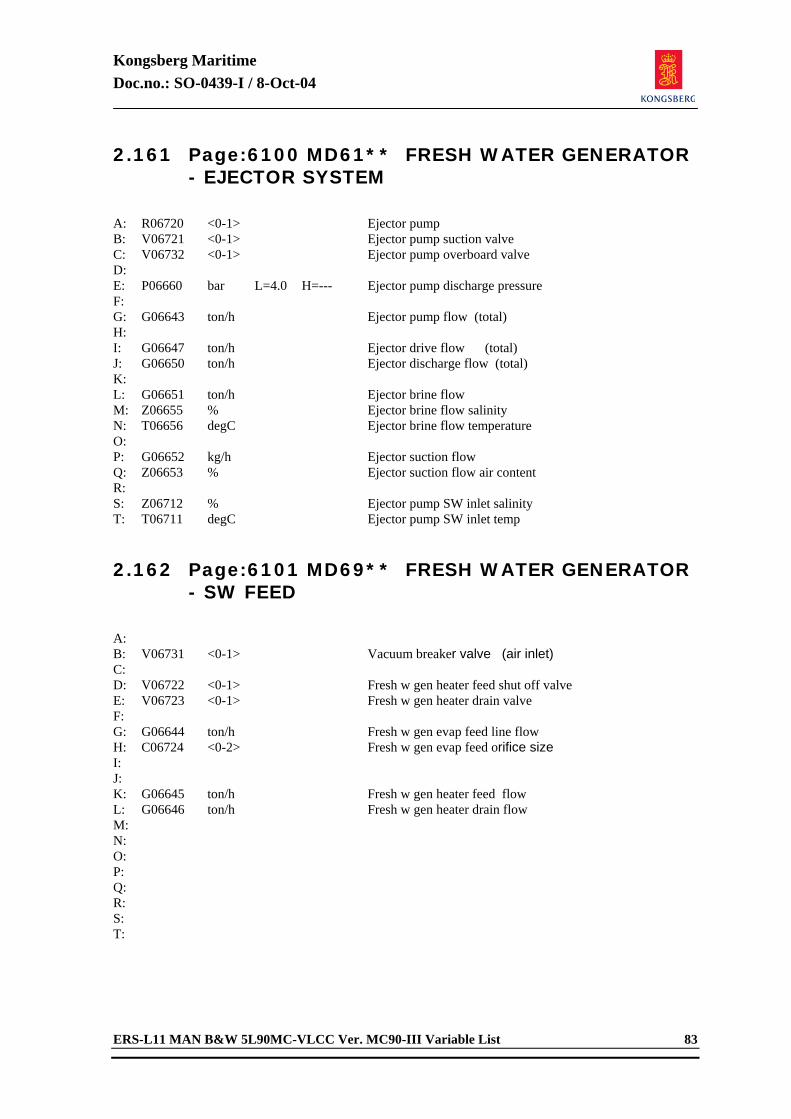
Kongsberg Maritime Doc.no.: SO-0439-I / 8-Oct-04
ERS-L11 MAN B&W 5L90MC-VLCC Ver. MC90-III Variable List 83
2.161 Page:6100 MD61** FRESH WATER GENERATOR - EJECTOR SYSTEM
A: R06720 <0-1> Ejector pump B: V06721 <0-1> Ejector pump suction valve C: V06732 <0-1> Ejector pump overboard valve D: E: P06660 bar L=4.0 H=--- Ejector pump discharge pressure F: G: G06643 ton/h Ejector pump flow (total) H: I: G06647 ton/h Ejector drive flow (total) J: G06650 ton/h Ejector discharge flow (total) K: L: G06651 ton/h Ejector brine flow M: Z06655 % Ejector brine flow salinity N: T06656 degC Ejector brine flow temperature O: P: G06652 kg/h Ejector suction flow Q: Z06653 % Ejector suction flow air content R: S: Z06712 % Ejector pump SW inlet salinity T: T06711 degC Ejector pump SW inlet temp 2.162 Page:6101 MD69** FRESH WATER GENERATOR
- SW FEED
A: B: V06731 <0-1> Vacuum breaker valve (air inlet) C: D: V06722 <0-1> Fresh w gen heater feed shut off valve E: V06723 <0-1> Fresh w gen heater drain valve F: G: G06644 ton/h Fresh w gen evap feed line flow H: C06724 <0-2> Fresh w gen evap feed orifice size I: J: K: G06645 ton/h Fresh w gen heater feed flow L: G06646 ton/h Fresh w gen heater drain flow M: N: O: P: Q: R: S: T:
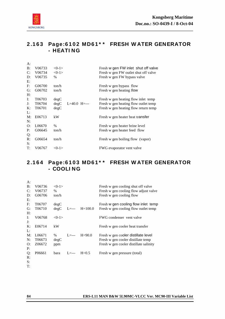
Kongsberg Maritime Doc.no.: SO-0439-I / 8-Oct-04
84 ERS-L11 MAN B&W 5L90MC-VLCC Ver. MC90-III Variable List
2.163 Page:6102 MD61** FRESH WATER GENERATOR - HEATING
A: B: V06733 <0-1> Fresh w gen FW inlet shut off valve C: V06734 <0-1> Fresh w gen FW outlet shut off valve D: V06735 % Fresh w gen FW bypass valve E: F: G06700 ton/h Fresh w gen bypass flow G: G06702 ton/h Fresh w gen heating flow H: I: T06703 degC Fresh w gen heating flow inlet temp J: T06704 degC L=40.0 H=--- Fresh w gen heating flow outlet temp K: T06701 degC Fresh w gen heating flow return temp L: M: E06713 kW Fresh w gen heater heat transfer N: O: L06670 % Fresh w gen heater brine level P: G06645 ton/h Fresh w gen heater feed flow Q: R: G06654 ton/h Fresh w gen boiling flow (vapor) S: T: V06767 <0-1> FWG evaporator vent valve 2.164 Page:6103 MD61** FRESH WATER GENERATOR
- COOLING
A: B: V06736 <0-1> Fresh w gen cooling shut off valve C: V06737 % Fresh w gen cooling flow adjust valve D: G06706 ton/h Fresh w gen cooling flow E: F: T06707 degC Fresh w gen cooling flow inlet temp G: T06710 degC L=--- H=100.0 Fresh w gen cooling flow outlet temp H: I: V06768 <0-1> FWG condenser vent valve J: K: E06714 kW Fresh w gen cooler heat transfer L: M: L06671 % L=--- H=90.0 Fresh w gen cooler distillate level N: T06673 degC Fresh w gen cooler distillate temp O: Z06672 ppm Fresh w gen cooler distillate salinity P: Q: P06661 bara L=--- H=0.5 Fresh w gen pressure (total) R: S: T:
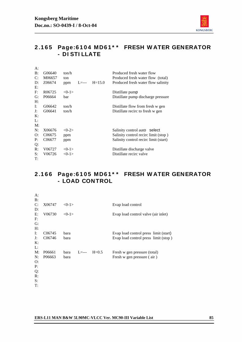
Kongsberg Maritime Doc.no.: SO-0439-I / 8-Oct-04
ERS-L11 MAN B&W 5L90MC-VLCC Ver. MC90-III Variable List 85
2.165 Page:6104 MD61** FRESH WATER GENERATOR - DISTILLATE
A: B: G06640 ton/h Produced fresh water flow C: M06657 ton Produced fresh water flow (total) D: Z06674 ppm L=--- H=15.0 Produced fresh water flow salinity E: F: R06725 <0-1> Distillate pump G: P06664 bar Distillate pump discharge pressure H: I: G06642 ton/h Distillate flow from fresh w gen J: G06641 ton/h Distillate recirc to fresh w gen K: L: M: N: X06676 <0-2> Salinity control auto select O: C06675 ppm Salinity control recirc limit (stop ) P: C06677 ppm Salinity control recirc limit (start) Q: R: V06727 <0-1> Distillate discharge valve S: V06726 <0-1> Distillate recirc valve T: 2.166 Page:6105 MD61** FRESH WATER GENERATOR
- LOAD CONTROL
A: B: C: X06747 <0-1> Evap load control D: E: V06730 <0-1> Evap load control valve (air inlet) F: G: H: I: C06745 bara Evap load control press limit (start) J: C06746 bara Evap load control press limit (stop ) K: L: M: P06661 bara L=--- H=0.5 Fresh w gen pressure (total) N: P06663 bara Fresh w gen pressure ( air ) O: P: Q: R: S: T:
Kongsberg Maritime Doc.no.: SO-0439-I / 8-Oct-04
86 ERS-L11 MAN B&W 5L90MC-VLCC Ver. MC90-III Variable List
2.167 Page:6107 MD61** FRESH WATER GENERATOR - ISOLATION
A: B: C: X06744 <0-1> Fresh w gen isolation D: E: F: G06740 ton/h Fresh w gen FW flow at isola (total) G: T06742 degC Fresh w gen FW temp at isola (inlet) H: I: G06741 ton/h Fresh w gen SW flow at isola (total) J: T06743 degC Fresh w gen SW temp at isola (inlet) K: L: M: N: O: P: Q: R: S: T: 2.168 Page:6190 MD61** CONFIGURABLE PAGE
A: B: C: D: E: F: G: H: I: J: K: L: M: N: O: P: Q: R: S: T:
Kongsberg Maritime Doc.no.: SO-0439-I / 8-Oct-04
ERS-L11 MAN B&W 5L90MC-VLCC Ver. MC90-III Variable List 87
2.169 Page:6200 MD62** SLUDGE TANK / INCINERATOR
A: L06432 m L=--- H=1.5 Sludge tank level (total) B: L06427 m Sludge tank level (oil only) C: L06433 m Sludge tank oil/wtr interface D: G06434 ton/h Sludge tank overflow E: F: G06435 ton/h Sludge tank influx (wtr) G: G06436 ton/h Sludge tank influx (oil) H: I: G06430 ton/h Sludge tank outlet flow J: V06431 <0-1> Sludge tank suction valve K: L: G06455 ton/h Bilge sep sludge flow M: Z06462 % Bilge sep sludge flow oil content N: R06441 <0-2> Incinerator pump O: X06442 <0-2> Incinerator flame P: G06440 ton/h Incinerator flow Q: V06448 <0-1> Sludge to shore valve R: X06449 <0-1> Sludge pipe shore connection S: R06443 <0-2> Sludge to shore pump T: G06444 ton/h Sludge to shore flow 2.170 Page:6201 MD62** BILGE WELL SYSTEM -
LEVELS
A: L06400 m L=--- H=0.5 Aft bilge well level B: Z06401 % Aft bilge well oil content C: G06402 ton/h Aft bilge well outlet flow D: V06403 <0-1> Aft bilge well suction valve E: F: L06422 m L=--- H=0.5 Fore bilge well level G: Z06423 % Fore bilge well oil content H: G06424 ton/h Fore bilge well outlet flow I: V06425 <0-1> Fore bilge well suction valve J: K: L06405 m L=--- H=0.5 Eroom bilge well level L: Z06407 % Eroom bilge well oil content M: G06410 ton/h Eroom bilge well outlet flow N: V06411 <0-1> Eroom bilge well suction valve O: P: Q: L06414 m L=--- H=0.5 Refrig. bilge well level R: Z06415 % Refrig. bilge well oil content S: G06416 ton/h Refrig. bilge well outlet flow T: V06417 <0-1> Refrig. bilge well suction valve
Kongsberg Maritime Doc.no.: SO-0439-I / 8-Oct-04
88 ERS-L11 MAN B&W 5L90MC-VLCC Ver. MC90-III Variable List
2.171 Page:6290 MD62** CONFIGURABLE PAGE
A: B: C: D: E: F: G: H: I: J: K: L: M: N: O: P: Q: R: S: T: 2.172 Page:6300 MD63** BILGE SEPARATOR (1)
A: R06470 <0-1> Bilge sep pump start/stop B: C: D: V06472 <0-1> Bilge sep overboard valve E: V06473 <0-1> Bilge sep recirc valve F: V06474 <0-1> Bilge sep sludge valve G: V06479 <0-1> Bilge sep by-pass valve H: V06494 <0-1> Bilge sep overboard stop valve I: V06495 <0-1> Bilge sep to clean water tank manual valve J: K: L: G06452 ton/h Bilge sep overboard flow M: G06451 ton/h Bilge sep clean bilge flow N: G06453 ton/h Bilge sep inlet flow O: G06454 ton/h Bilge sep outlet flow P: G06455 ton/h Bilge sep sludge flow Q: R: Z06463 ppm L=--- H=15.0 Bilge sep flow oil ppm (measuring cell) S: Z06460 % Bilge sep inlet flow oil content T: Z06462 % Bilge sep sludge flow oil content
Kongsberg Maritime Doc.no.: SO-0439-I / 8-Oct-04
ERS-L11 MAN B&W 5L90MC-VLCC Ver. MC90-III Variable List 89
2.173 Page:6301 MD63** BILGE SEPARATOR (2)
A: B: C: X06481 <0-1> Bilge sep auto switch D: X06482 <0-1> Bilge sep trip indication E: F: X06475 <0-1> Bilge sep heater switch G: E06467 kW Bilge sep heater power H: T06466 degC L=65.0 H=95.0 Bilge sep oil/water settling temp I: L06465 % L=--- H=40.0 Bilge sep oil/water interface level J: K: L: M: C06464 ppm Bilge sep recirc ppm limit N: O: X06496 % L=--- H=20.0 Bilge pump auto time on (% of offtime) P: Q: L06488 m Bilge sep pump start limit R: L06489 m Bilge sep pump stop limit S: T: 2.174 Page:6302 MD63** CLEAN BILGE WATER TANK
A: B: L06490 m L=--- H=0.8 Clean bilge water tank level C: D: Z06491 % Clean bilge water tank oil content E: F: G06451 ton/h Bilge sep clean bilge flow G: G06492 ton/h Clean bilge water tank outlet flow H: I: V06493 <0-1> Clean bilge water tank suction valve J: K: V06494 <0-1> Bilge sep overboard stop valve L: V06495 <0-1> Bilge sep to clean water tank manual valve M: N: O: P: Q: R: S: T:

Kongsberg Maritime Doc.no.: SO-0439-I / 8-Oct-04
90 ERS-L11 MAN B&W 5L90MC-VLCC Ver. MC90-III Variable List
2.175 Page:6390 MD63** CONFIGURABLE PAGE
A: B: C: D: E: F: G: H: I: J: K: L: M: N: O: P: Q: R: S: T: 2.176 Page:6400 MD64** REFRIG SYSTEM -
COMPRESSOR
A: X06524 <0-5> L=--- H=1.0 Refrig comp trip indication B: C: X06523 <0-3> Refrig comp start inhibit D: R06525 <0-1> Refrig comp start E: F: E06533 kW L=--- H=230.0 Refrig comp electric power G: Z06534 % Refrig comp efficiency (overall) H: I: P06527 bar L=--- H=15.0 Refrig comp discharge press J: P06530 bar L=-0.7 H=--- Refrig comp suction press K: Z06531 - Refrig comp pressure ratio L: M: T06532 degC L=--- H=90.0 Refrig comp discharge temp N: G06526 kg/s Refrig comp discharge flow O: P: Q: T06567 degC L=10.0 H=55.0 Refrig comp LO inlet temp R: P06571 bar L=1.5 H=--- Refrig comp LO inlet diff press S: T: T06535 degC L=--- H=80.0 Refrig comp thrust bearing temp
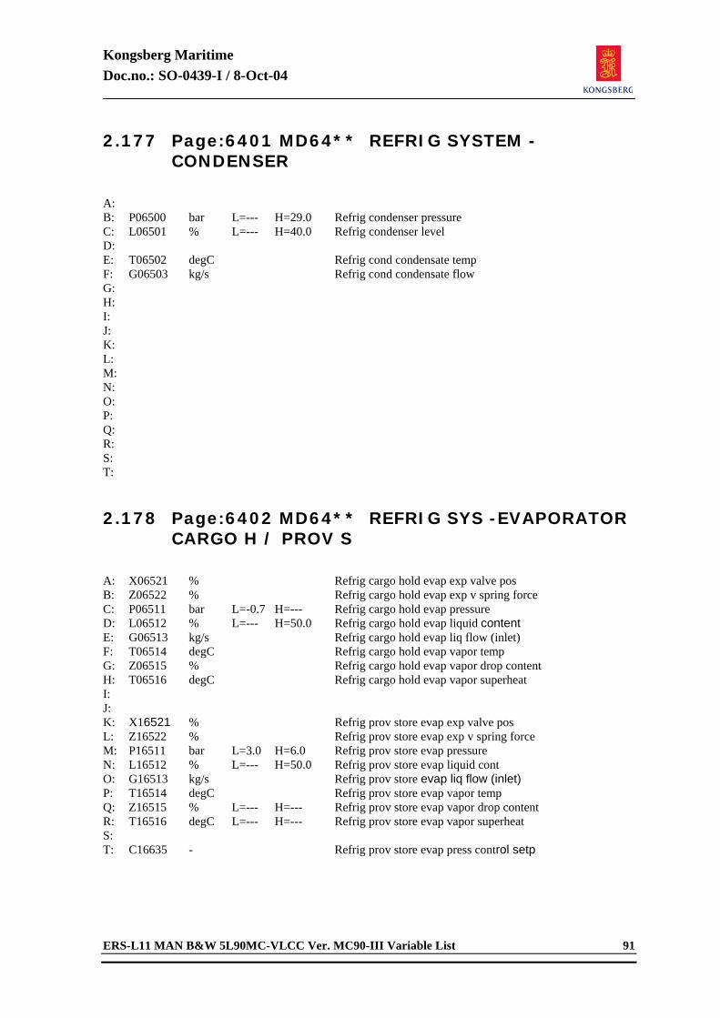
Kongsberg Maritime Doc.no.: SO-0439-I / 8-Oct-04
ERS-L11 MAN B&W 5L90MC-VLCC Ver. MC90-III Variable List 91
2.177 Page:6401 MD64** REFRIG SYSTEM - CONDENSER
A: B: P06500 bar L=--- H=29.0 Refrig condenser pressure C: L06501 % L=--- H=40.0 Refrig condenser level D: E: T06502 degC Refrig cond condensate temp F: G06503 kg/s Refrig cond condensate flow G: H: I: J: K: L: M: N: O: P: Q: R: S: T: 2.178 Page:6402 MD64** REFRIG SYS -EVAPORATOR
CARGO H / PROV S
A: X06521 % Refrig cargo hold evap exp valve pos B: Z06522 % Refrig cargo hold evap exp v spring force C: P06511 bar L=-0.7 H=--- Refrig cargo hold evap pressure D: L06512 % L=--- H=50.0 Refrig cargo hold evap liquid content E: G06513 kg/s Refrig cargo hold evap liq flow (inlet) F: T06514 degC Refrig cargo hold evap vapor temp G: Z06515 % Refrig cargo hold evap vapor drop content H: T06516 degC Refrig cargo hold evap vapor superheat I: J: K: X16521 % Refrig prov store evap exp valve pos L: Z16522 % Refrig prov store evap exp v spring force M: P16511 bar L=3.0 H=6.0 Refrig prov store evap pressure N: L16512 % L=--- H=50.0 Refrig prov store evap liquid cont O: G16513 kg/s Refrig prov store evap liq flow (inlet) P: T16514 degC Refrig prov store evap vapor temp Q: Z16515 % L=--- H=--- Refrig prov store evap vapor drop content R: T16516 degC L=--- H=--- Refrig prov store evap vapor superheat S: T: C16635 - Refrig prov store evap press control setp
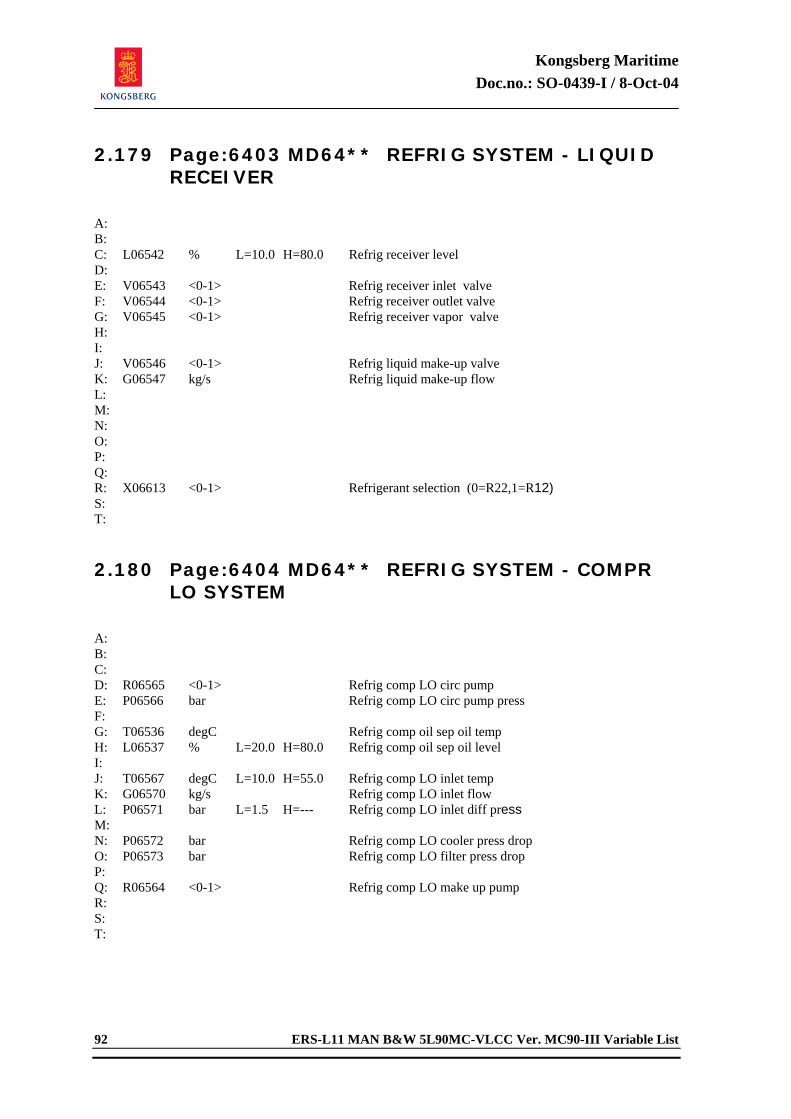
Kongsberg Maritime Doc.no.: SO-0439-I / 8-Oct-04
92 ERS-L11 MAN B&W 5L90MC-VLCC Ver. MC90-III Variable List
2.179 Page:6403 MD64** REFRIG SYSTEM - LIQUID RECEIVER
A: B: C: L06542 % L=10.0 H=80.0 Refrig receiver level D: E: V06543 <0-1> Refrig receiver inlet valve F: V06544 <0-1> Refrig receiver outlet valve G: V06545 <0-1> Refrig receiver vapor valve H: I: J: V06546 <0-1> Refrig liquid make-up valve K: G06547 kg/s Refrig liquid make-up flow L: M: N: O: P: Q: R: X06613 <0-1> Refrigerant selection (0=R22,1=R12) S: T: 2.180 Page:6404 MD64** REFRIG SYSTEM - COMPR
LO SYSTEM
A: B: C: D: R06565 <0-1> Refrig comp LO circ pump E: P06566 bar Refrig comp LO circ pump press F: G: T06536 degC Refrig comp oil sep oil temp H: L06537 % L=20.0 H=80.0 Refrig comp oil sep oil level I: J: T06567 degC L=10.0 H=55.0 Refrig comp LO inlet temp K: G06570 kg/s Refrig comp LO inlet flow L: P06571 bar L=1.5 H=--- Refrig comp LO inlet diff press M: N: P06572 bar Refrig comp LO cooler press drop O: P06573 bar Refrig comp LO filter press drop P: Q: R06564 <0-1> Refrig comp LO make up pump R: S: T:
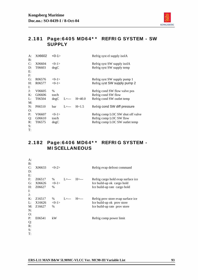
Kongsberg Maritime Doc.no.: SO-0439-I / 8-Oct-04
ERS-L11 MAN B&W 5L90MC-VLCC Ver. MC90-III Variable List 93
2.181 Page:6405 MD64** REFRIG SYSTEM - SW SUPPLY
A: X06602 <0-1> Refrig syst el supply isolA B: C: X06604 <0-1> Refrig syst SW supply isolA D: T06603 degC Refrig syst SW supply temp E: F: G: R06576 <0-1> Refrig syst SW supply pump 1 H: R06577 <0-1> Refrig syst SW supply pump 2 I: J: V06605 % Refrig cond SW flow valve pos K: G06606 ton/h Refrig cond SW flow L: T06504 degC L=--- H=40.0 Refrig cond SW outlet temp M: N: P06510 bar L=--- H=1.5 Refrig cond SW diff pressure O: P: V06607 <0-1> Refrig comp LOC SW shut off valve Q: G06610 ton/h Refrig comp LOC SW flow R: T06575 degC Refrig comp LOC SW outlet temp S: T: 2.182 Page:6406 MD64** REFRIG SYSTEM -
MISCELLANEOUS
A: B: C: X06633 <0-2> Refrig evap defrost command D: E: F: Z06517 % L=--- H=--- Refrig cargo hold evap surface ice G: X06626 <0-1> Ice build-up ok cargo hold H: Z06627 % Ice build-up rate cargo hold I: J: K: Z16517 % L=--- H=--- Refrig prov store evap surface ice L: X16626 <0-1> Ice build-up ok prov store M: Z16627 % Ice build-up rate prov store N: O: P: E06541 kW Refrig comp power limit Q: R: S: T:
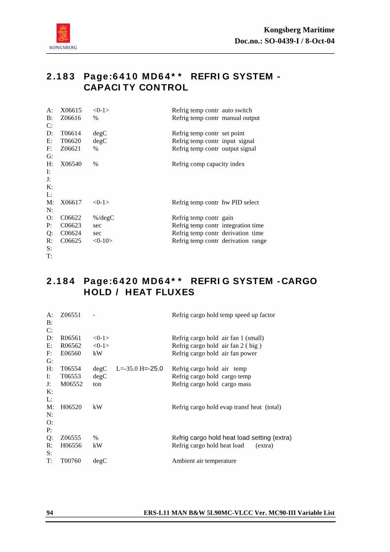
Kongsberg Maritime Doc.no.: SO-0439-I / 8-Oct-04
94 ERS-L11 MAN B&W 5L90MC-VLCC Ver. MC90-III Variable List
2.183 Page:6410 MD64** REFRIG SYSTEM - CAPACITY CONTROL
A: X06615 <0-1> Refrig temp contr auto switch B: Z06616 % Refrig temp contr manual output C: D: T06614 degC Refrig temp contr set point E: T06620 degC Refrig temp contr input signal F: Z06621 % Refrig temp contr output signal G: H: X06540 % Refrig comp capacity index I: J: K: L: M: X06617 <0-1> Refrig temp contr hw PID select N: O: C06622 %/degC Refrig temp contr gain P: C06623 sec Refrig temp contr integration time Q: C06624 sec Refrig temp contr derivation time R: C06625 <0-10> Refrig temp contr derivation range S: T: 2.184 Page:6420 MD64** REFRIG SYSTEM -CARGO
HOLD / HEAT FLUXES
A: Z06551 - Refrig cargo hold temp speed up factor B: C: D: R06561 <0-1> Refrig cargo hold air fan 1 (small) E: R06562 <0-1> Refrig cargo hold air fan 2 ( big ) F: E06560 kW Refrig cargo hold air fan power G: H: T06554 degC L=-35.0 H=-25.0 Refrig cargo hold air temp I: T06553 degC Refrig cargo hold cargo temp J: M06552 ton Refrig cargo hold cargo mass K: L: M: H06520 kW Refrig cargo hold evap transf heat (total) N: O: P: Q: Z06555 % Refrig cargo hold heat load setting (extra) R: H06556 kW Refrig cargo hold heat load (extra) S: T: T00760 degC Ambient air temperature
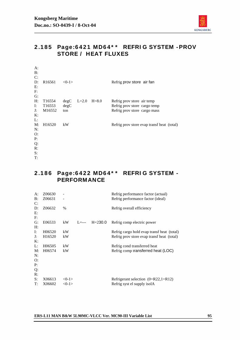
Kongsberg Maritime Doc.no.: SO-0439-I / 8-Oct-04
ERS-L11 MAN B&W 5L90MC-VLCC Ver. MC90-III Variable List 95
2.185 Page:6421 MD64** REFRIG SYSTEM -PROV STORE / HEAT FLUXES
A: B: C: D: R16561 <0-1> Refrig prov store air fan E: F: G: H: T16554 degC L=2.0 H=8.0 Refrig prov store air temp I: T16553 degC Refrig prov store cargo temp J: M16552 ton Refrig prov store cargo mass K: L: M: H16520 kW Refrig prov store evap transf heat (total) N: O: P: Q: R: S: T: 2.186 Page:6422 MD64** REFRIG SYSTEM -
PERFORMANCE
A: Z06630 - Refrig performance factor (actual) B: Z06631 - Refrig performance factor (ideal) C: D: Z06632 % Refrig overall efficiency E: F: G: E06533 kW L=--- H=230.0 Refrig comp electric power H: I: H06520 kW Refrig cargo hold evap transf heat (total) J: H16520 kW Refrig prov store evap transf heat (total) K: L: H06505 kW Refrig cond transferred heat M: H06574 kW Refrig comp transferred heat (LOC) N: O: P: Q: R: S: X06613 <0-1> Refrigerant selection (0=R22,1=R12) T: X06602 <0-1> Refrig syst el supply isolA
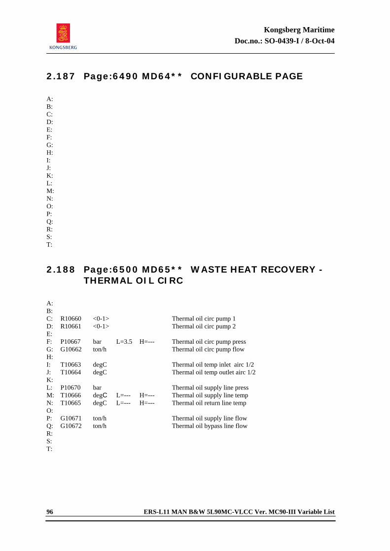
Kongsberg Maritime Doc.no.: SO-0439-I / 8-Oct-04
96 ERS-L11 MAN B&W 5L90MC-VLCC Ver. MC90-III Variable List
2.187 Page:6490 MD64** CONFIGURABLE PAGE
A: B: C: D: E: F: G: H: I: J: K: L: M: N: O: P: Q: R: S: T: 2.188 Page:6500 MD65** WASTE HEAT RECOVERY -
THERMAL OIL CIRC
A: B: C: R10660 <0-1> Thermal oil circ pump 1 D: R10661 <0-1> Thermal oil circ pump 2 E: F: P10667 bar L=3.5 H=--- Thermal oil circ pump press G: G10662 ton/h Thermal oil circ pump flow H: I: T10663 degC Thermal oil temp inlet airc 1/2 J: T10664 degC Thermal oil temp outlet airc 1/2 K: L: P10670 bar Thermal oil supply line press M: T10666 degC L=--- H=--- Thermal oil supply line temp N: T10665 degC L=--- H=--- Thermal oil return line temp O: P: G10671 ton/h Thermal oil supply line flow Q: G10672 ton/h Thermal oil bypass line flow R: S: T:
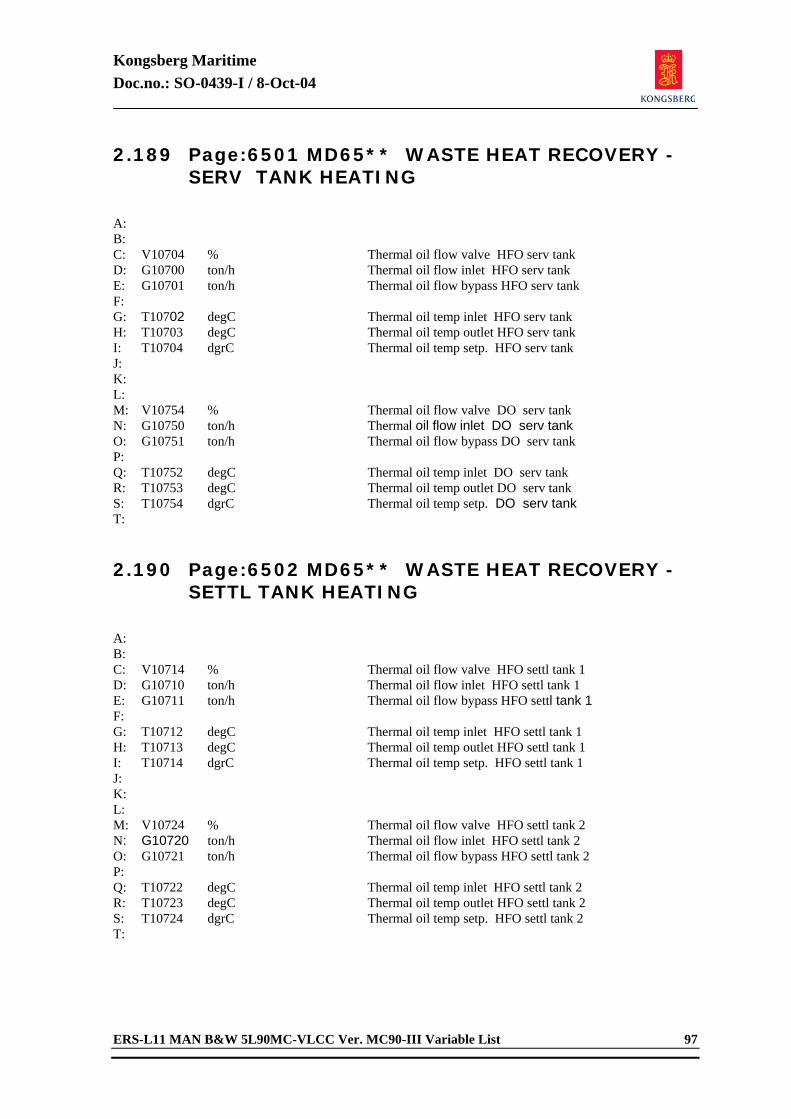
Kongsberg Maritime Doc.no.: SO-0439-I / 8-Oct-04
ERS-L11 MAN B&W 5L90MC-VLCC Ver. MC90-III Variable List 97
2.189 Page:6501 MD65** WASTE HEAT RECOVERY - SERV TANK HEATING
A: B: C: V10704 % Thermal oil flow valve HFO serv tank D: G10700 ton/h Thermal oil flow inlet HFO serv tank E: G10701 ton/h Thermal oil flow bypass HFO serv tank F: G: T10702 degC Thermal oil temp inlet HFO serv tank H: T10703 degC Thermal oil temp outlet HFO serv tank I: T10704 dgrC Thermal oil temp setp. HFO serv tank J: K: L: M: V10754 % Thermal oil flow valve DO serv tank N: G10750 ton/h Thermal oil flow inlet DO serv tank O: G10751 ton/h Thermal oil flow bypass DO serv tank P: Q: T10752 degC Thermal oil temp inlet DO serv tank R: T10753 degC Thermal oil temp outlet DO serv tank S: T10754 dgrC Thermal oil temp setp. DO serv tank T: 2.190 Page:6502 MD65** WASTE HEAT RECOVERY -
SETTL TANK HEATING
A: B: C: V10714 % Thermal oil flow valve HFO settl tank 1 D: G10710 ton/h Thermal oil flow inlet HFO settl tank 1 E: G10711 ton/h Thermal oil flow bypass HFO settl tank 1 F: G: T10712 degC Thermal oil temp inlet HFO settl tank 1 H: T10713 degC Thermal oil temp outlet HFO settl tank 1 I: T10714 dgrC Thermal oil temp setp. HFO settl tank 1 J: K: L: M: V10724 % Thermal oil flow valve HFO settl tank 2 N: G10720 ton/h Thermal oil flow inlet HFO settl tank 2 O: G10721 ton/h Thermal oil flow bypass HFO settl tank 2 P: Q: T10722 degC Thermal oil temp inlet HFO settl tank 2 R: T10723 degC Thermal oil temp outlet HFO settl tank 2 S: T10724 dgrC Thermal oil temp setp. HFO settl tank 2 T:
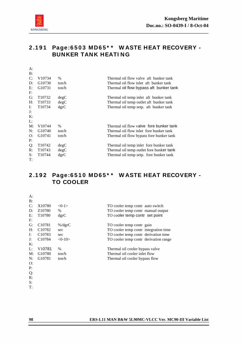
Kongsberg Maritime Doc.no.: SO-0439-I / 8-Oct-04
98 ERS-L11 MAN B&W 5L90MC-VLCC Ver. MC90-III Variable List
2.191 Page:6503 MD65** WASTE HEAT RECOVERY - BUNKER TANK HEATING
A: B: C: V10734 % Thermal oil flow valve aft bunker tank D: G10730 ton/h Thermal oil flow inlet aft bunker tank E: G10731 ton/h Thermal oil flow bypass aft bunker tank F: G: T10732 degC Thermal oil temp inlet aft bunker tank H: T10733 degC Thermal oil temp outlet aft bunker tank I: T10734 dgrC Thermal oil temp setp. aft bunker tank J: K: L: M: V10744 % Thermal oil flow valve fore bunker tank N: G10740 ton/h Thermal oil flow inlet fore bunker tank O: G10741 ton/h Thermal oil flow bypass fore bunker tank P: Q: T10742 degC Thermal oil temp inlet fore bunker tank R: T10743 degC Thermal oil temp outlet fore bunker tank S: T10744 dgrC Thermal oil temp setp. fore bunker tank T: 2.192 Page:6510 MD65** WASTE HEAT RECOVERY -
TO COOLER
A: B: C: X10780 <0-1> TO cooler temp contr auto switch D: Z10780 % TO cooler temp contr manual output E: T10780 dgrC TO cooler temp contr set point F: G: C10781 %/dgrC TO cooler temp contr gain H: C10782 sec TO cooler temp contr integration time I: C10783 sec TO cooler temp contr derivation time J: C10784 <0-10> TO cooler temp contr derivation range K: L: V10781 % Thermal oil cooler bypass valve M: G10780 ton/h Thermal oil cooler inlet flow N: G10781 ton/h Thermal oil cooler bypass flow O: P: Q: R: S: T:
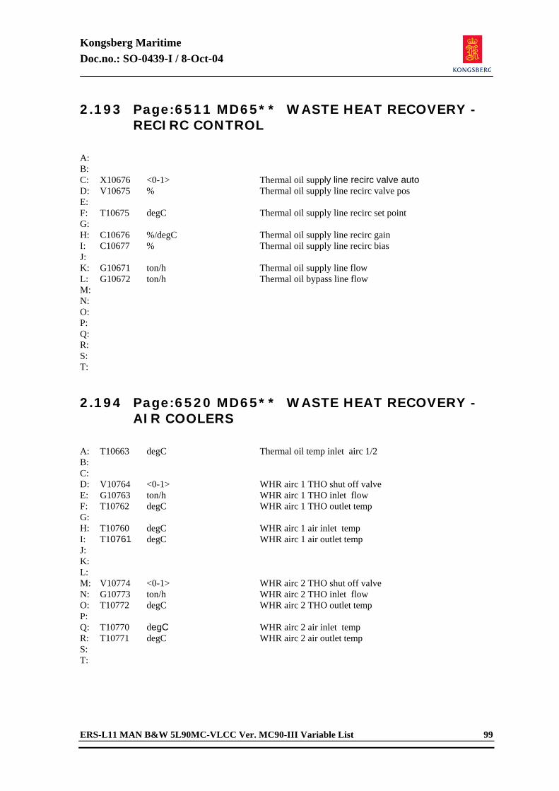
Kongsberg Maritime Doc.no.: SO-0439-I / 8-Oct-04
ERS-L11 MAN B&W 5L90MC-VLCC Ver. MC90-III Variable List 99
2.193 Page:6511 MD65** WASTE HEAT RECOVERY - RECIRC CONTROL
A: B: C: X10676 <0-1> Thermal oil supply line recirc valve auto D: V10675 % Thermal oil supply line recirc valve pos E: F: T10675 degC Thermal oil supply line recirc set point G: H: C10676 %/degC Thermal oil supply line recirc gain I: C10677 % Thermal oil supply line recirc bias J: K: G10671 ton/h Thermal oil supply line flow L: G10672 ton/h Thermal oil bypass line flow M: N: O: P: Q: R: S: T: 2.194 Page:6520 MD65** WASTE HEAT RECOVERY -
AIR COOLERS
A: T10663 degC Thermal oil temp inlet airc 1/2 B: C: D: V10764 <0-1> WHR airc 1 THO shut off valve E: G10763 ton/h WHR airc 1 THO inlet flow F: T10762 degC WHR airc 1 THO outlet temp G: H: T10760 degC WHR airc 1 air inlet temp I: T10761 degC WHR airc 1 air outlet temp J: K: L: M: V10774 <0-1> WHR airc 2 THO shut off valve N: G10773 ton/h WHR airc 2 THO inlet flow O: T10772 degC WHR airc 2 THO outlet temp P: Q: T10770 degC WHR airc 2 air inlet temp R: T10771 degC WHR airc 2 air outlet temp S: T:
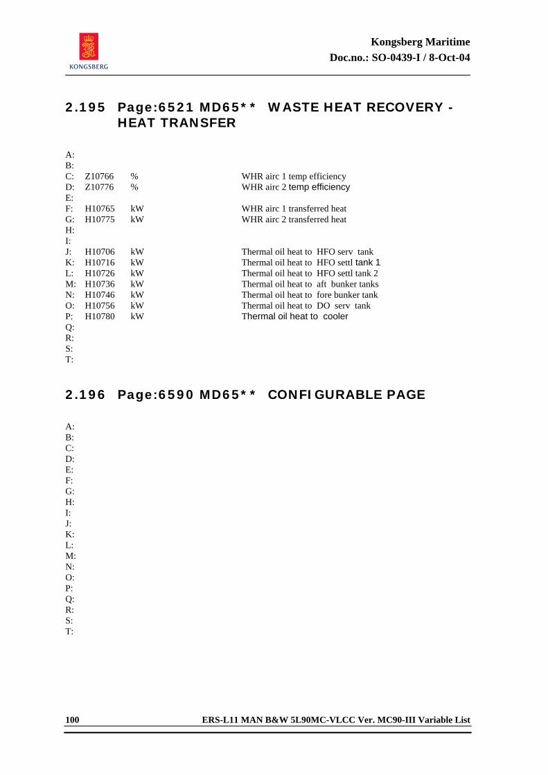
Kongsberg Maritime Doc.no.: SO-0439-I / 8-Oct-04
100 ERS-L11 MAN B&W 5L90MC-VLCC Ver. MC90-III Variable List
2.195 Page:6521 MD65** WASTE HEAT RECOVERY - HEAT TRANSFER
A: B: C: Z10766 % WHR airc 1 temp efficiency D: Z10776 % WHR airc 2 temp efficiency E: F: H10765 kW WHR airc 1 transferred heat G: H10775 kW WHR airc 2 transferred heat H: I: J: H10706 kW Thermal oil heat to HFO serv tank K: H10716 kW Thermal oil heat to HFO settl tank 1 L: H10726 kW Thermal oil heat to HFO settl tank 2 M: H10736 kW Thermal oil heat to aft bunker tanks N: H10746 kW Thermal oil heat to fore bunker tank O: H10756 kW Thermal oil heat to DO serv tank P: H10780 kW Thermal oil heat to cooler Q: R: S: T: 2.196 Page:6590 MD65** CONFIGURABLE PAGE
A: B: C: D: E: F: G: H: I: J: K: L: M: N: O: P: Q: R: S: T:
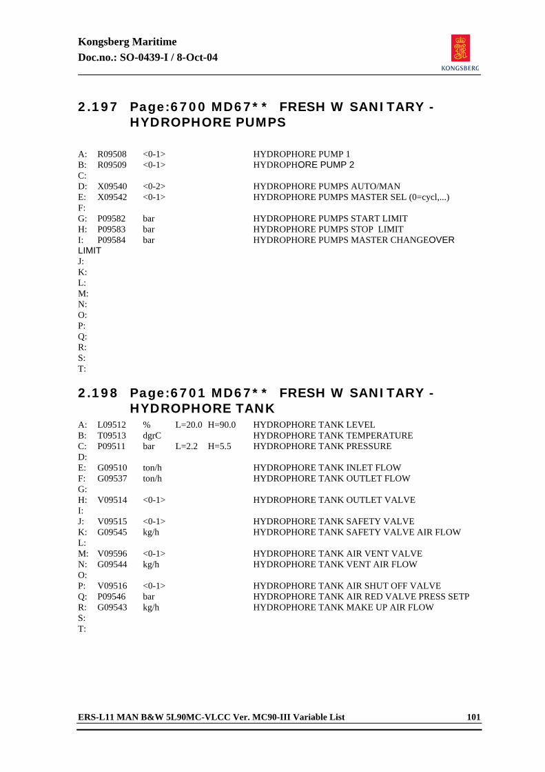
Kongsberg Maritime Doc.no.: SO-0439-I / 8-Oct-04
ERS-L11 MAN B&W 5L90MC-VLCC Ver. MC90-III Variable List 101
2.197 Page:6700 MD67** FRESH W SANITARY - HYDROPHORE PUMPS
A: R09508 <0-1> HYDROPHORE PUMP 1 B: R09509 <0-1> HYDROPHORE PUMP 2 C: D: X09540 <0-2> HYDROPHORE PUMPS AUTO/MAN E: X09542 <0-1> HYDROPHORE PUMPS MASTER SEL (0=cycl,...) F: G: P09582 bar HYDROPHORE PUMPS START LIMIT H: P09583 bar HYDROPHORE PUMPS STOP LIMIT I: P09584 bar HYDROPHORE PUMPS MASTER CHANGEOVER LIMIT J: K: L: M: N: O: P: Q: R: S: T: 2.198 Page:6701 MD67** FRESH W SANITARY -
HYDROPHORE TANK A: L09512 % L=20.0 H=90.0 HYDROPHORE TANK LEVEL B: T09513 dgrC HYDROPHORE TANK TEMPERATURE C: P09511 bar L=2.2 H=5.5 HYDROPHORE TANK PRESSURE D: E: G09510 ton/h HYDROPHORE TANK INLET FLOW F: G09537 ton/h HYDROPHORE TANK OUTLET FLOW G: H: V09514 <0-1> HYDROPHORE TANK OUTLET VALVE I: J: V09515 <0-1> HYDROPHORE TANK SAFETY VALVE K: G09545 kg/h HYDROPHORE TANK SAFETY VALVE AIR FLOW L: M: V09596 <0-1> HYDROPHORE TANK AIR VENT VALVE N: G09544 kg/h HYDROPHORE TANK VENT AIR FLOW O: P: V09516 <0-1> HYDROPHORE TANK AIR SHUT OFF VALVE Q: P09546 bar HYDROPHORE TANK AIR RED VALVE PRESS SETP R: G09543 kg/h HYDROPHORE TANK MAKE UP AIR FLOW S: T:
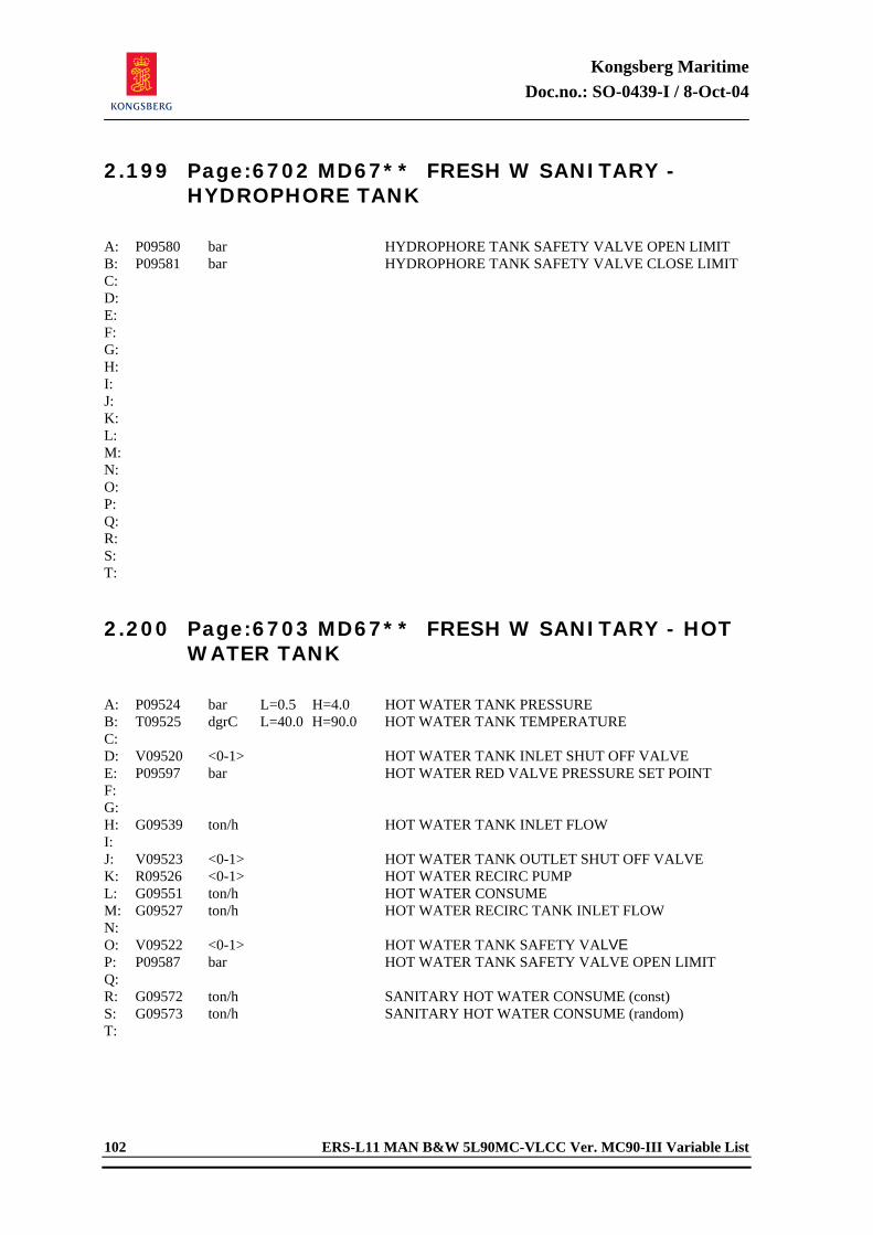
Kongsberg Maritime Doc.no.: SO-0439-I / 8-Oct-04
102 ERS-L11 MAN B&W 5L90MC-VLCC Ver. MC90-III Variable List
2.199 Page:6702 MD67** FRESH W SANITARY - HYDROPHORE TANK
A: P09580 bar HYDROPHORE TANK SAFETY VALVE OPEN LIMIT B: P09581 bar HYDROPHORE TANK SAFETY VALVE CLOSE LIMIT C: D: E: F: G: H: I: J: K: L: M: N: O: P: Q: R: S: T: 2.200 Page:6703 MD67** FRESH W SANITARY - HOT
WATER TANK
A: P09524 bar L=0.5 H=4.0 HOT WATER TANK PRESSURE B: T09525 dgrC L=40.0 H=90.0 HOT WATER TANK TEMPERATURE C: D: V09520 <0-1> HOT WATER TANK INLET SHUT OFF VALVE E: P09597 bar HOT WATER RED VALVE PRESSURE SET POINT F: G: H: G09539 ton/h HOT WATER TANK INLET FLOW I: J: V09523 <0-1> HOT WATER TANK OUTLET SHUT OFF VALVE K: R09526 <0-1> HOT WATER RECIRC PUMP L: G09551 ton/h HOT WATER CONSUME M: G09527 ton/h HOT WATER RECIRC TANK INLET FLOW N: O: V09522 <0-1> HOT WATER TANK SAFETY VALVE P: P09587 bar HOT WATER TANK SAFETY VALVE OPEN LIMIT Q: R: G09572 ton/h SANITARY HOT WATER CONSUME (const) S: G09573 ton/h SANITARY HOT WATER CONSUME (random) T:
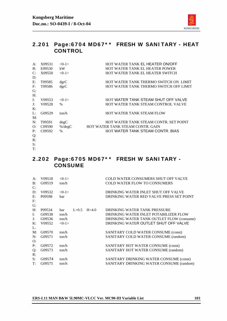
Kongsberg Maritime Doc.no.: SO-0439-I / 8-Oct-04
ERS-L11 MAN B&W 5L90MC-VLCC Ver. MC90-III Variable List 103
2.201 Page:6704 MD67** FRESH W SANITARY - HEAT CONTROL
A: X09531 <0-1> HOT WATER TANK EL HEATER ON/OFF B: E09530 kW HOT WATER TANK EL HEATER POWER C: X09550 <0-1> HOT WATER TANK EL HEATER SWITCH D: E: T09585 dgrC HOT WATER TANK THERMO SWITCH ON LIMIT F: T09586 dgrC HOT WATER TANK THERMO SWITCH OFF LIMIT G: H: I: V09553 <0-1> HOT WATER TANK STEAM SHUT OFF VALVE J: V09528 % HOT WATER TANK STEAM CONTROL VALVE K: L: G09529 ton/h HOT WATER TANK STEAM FLOW M: N: T09591 degC HOT WATER TANK STEAM CONTR. SET POINT O: C09590 %/degC HOT WATER TANK STEAM CONTR. GAIN P: C09592 % HOT WATER TANK STEAM CONTR. BIAS Q: R: S: T: 2.202 Page:6705 MD67** FRESH W SANITARY -
CONSUME
A: V09518 <0-1> COLD WATER CONSUMERS SHUT OFF VALVE B: G09519 ton/h COLD WATER FLOW TO CONSUMERS C: D: V09532 <0-1> DRINKING WATER INLET SHUT OFF VALVE E: P09598 bar DRINKING WATER RED VALVE PRESS SET POINT F: G: H: P09534 bar L=0.5 H=4.0 DRINKING WATER TANK PRESSURE I: G09538 ton/h DRINKING WATER INLET POTABILIZER FLOW J: G09536 ton/h DRINKING WATER TANK OUTLET FLOW (consume) K: V09552 <0-1> DRINKING WATER OUTLET SHUT OFF VALVE L: M: G09570 ton/h SANITARY COLD WATER CONSUME (const) N: G09571 ton/h SANITARY COLD WATER CONSUME (random) O: P: G09572 ton/h SANITARY HOT WATER CONSUME (const) Q: G09573 ton/h SANITARY HOT WATER CONSUME (random) R: S: G09574 ton/h SANITARY DRINKING WATER CONSUME (const) T: G09575 ton/h SANITARY DRINKING WATER CONSUME (random)
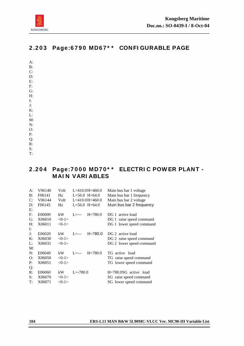
Kongsberg Maritime Doc.no.: SO-0439-I / 8-Oct-04
104 ERS-L11 MAN B&W 5L90MC-VLCC Ver. MC90-III Variable List
2.203 Page:6790 MD67** CONFIGURABLE PAGE
A: B: C: D: E: F: G: H: I: J: K: L: M: N: O: P: Q: R: S: T: 2.204 Page:7000 MD70** ELECTRIC POWER PLANT -
MAIN VARIABLES
A: V06140 Volt L=410.0 H=460.0 Main bus bar 1 voltage B: F06141 Hz L=56.0 H=64.0 Main bus bar 1 frequency C: V06144 Volt L=410.0 H=460.0 Main bus bar 2 voltage D: F06145 Hz L=56.0 H=64.0 Main bus bar 2 frequency E: F: E06000 kW L=--- H=780.0 DG 1 active load G: X06010 <0-1> DG 1 raise speed command H: X06011 <0-1> DG 1 lower speed command I: J: E06020 kW L=--- H=780.0 DG 2 active load K: X06030 <0-1> DG 2 raise speed command L: X06031 <0-1> DG 2 lower speed command M: N: E06040 kW L=--- H=780.0 TG active load O: X06050 <0-1> TG raise speed command P: X06051 <0-1> TG lower speed command Q: R: E06060 kW L=-780.0 H=780.0 SG active load S: X06070 <0-1> SG raise speed command T: X06071 <0-1> SG lower speed command
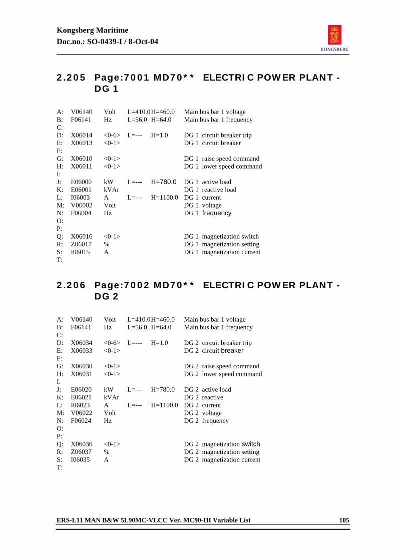
Kongsberg Maritime Doc.no.: SO-0439-I / 8-Oct-04
ERS-L11 MAN B&W 5L90MC-VLCC Ver. MC90-III Variable List 105
2.205 Page:7001 MD70** ELECTRIC POWER PLANT - DG 1
A: V06140 Volt L=410.0 H=460.0 Main bus bar 1 voltage B: F06141 Hz L=56.0 H=64.0 Main bus bar 1 frequency C: D: X06014 <0-6> L=--- H=1.0 DG 1 circuit breaker trip E: X06013 <0-1> DG 1 circuit breaker F: G: X06010 <0-1> DG 1 raise speed command H: X06011 <0-1> DG 1 lower speed command I: J: E06000 kW L=--- H=780.0 DG 1 active load K: E06001 kVAr DG 1 reactive load L: I06003 A L=--- H=1100.0 DG 1 current M: V06002 Volt DG 1 voltage N: F06004 Hz DG 1 frequency O: P: Q: X06016 <0-1> DG 1 magnetization switch R: Z06017 % DG 1 magnetization setting S: I06015 A DG 1 magnetization current T: 2.206 Page:7002 MD70** ELECTRIC POWER PLANT -
DG 2
A: V06140 Volt L=410.0 H=460.0 Main bus bar 1 voltage B: F06141 Hz L=56.0 H=64.0 Main bus bar 1 frequency C: D: X06034 <0-6> L=--- H=1.0 DG 2 circuit breaker trip E: X06033 <0-1> DG 2 circuit breaker F: G: X06030 <0-1> DG 2 raise speed command H: X06031 <0-1> DG 2 lower speed command I: J: E06020 kW L=--- H=780.0 DG 2 active load K: E06021 kVAr DG 2 reactive L: I06023 A L=--- H=1100.0 DG 2 current M: V06022 Volt DG 2 voltage N: F06024 Hz DG 2 frequency O: P: Q: X06036 <0-1> DG 2 magnetization switch R: Z06037 % DG 2 magnetization setting S: I06035 A DG 2 magnetization current T:
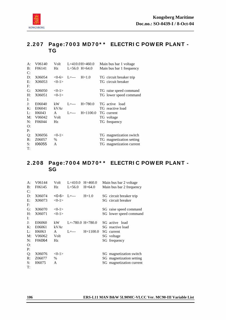
Kongsberg Maritime Doc.no.: SO-0439-I / 8-Oct-04
106 ERS-L11 MAN B&W 5L90MC-VLCC Ver. MC90-III Variable List
2.207 Page:7003 MD70** ELECTRIC POWER PLANT - TG
A: V06140 Volt L=410.0 H=460.0 Main bus bar 1 voltage B: F06141 Hz L=56.0 H=64.0 Main bus bar 1 frequency C: D: X06054 <0-6> L=--- H=1.0 TG circuit breaker trip E: X06053 <0-1> TG circuit breaker F: G: X06050 <0-1> TG raise speed command H: X06051 <0-1> TG lower speed command I: J: E06040 kW L=--- H=780.0 TG active load K: E06041 kVAr TG reactive load L: I06043 A L=--- H=1100.0 TG current M: V06042 Volt TG voltage N: F06044 Hz TG frequency O: P: Q: X06056 <0-1> TG magnetization switch R: Z06057 % TG magnetization setting S: I06055 A TG magnetization current T: 2.208 Page:7004 MD70** ELECTRIC POWER PLANT -
SG
A: V06144 Volt L=410.0 H=460.0 Main bus bar 2 voltage B: F06145 Hz L=56.0 H=64.0 Main bus bar 2 frequency C: D: X06074 <0-6> L=--- H=1.0 SG circuit breaker trip E: X06073 <0-1> SG circuit breaker F: G: X06070 <0-1> SG raise speed command H: X06071 <0-1> SG lower speed command I: J: E06060 kW L=-780.0 H=780.0 SG active load K: E06061 kVAr SG reactive load L: I06063 A L=--- H=1100.0 SG current M: V06062 Volt SG voltage N: F06064 Hz SG frequency O: P: Q: X06076 <0-1> SG magnetization switch R: Z06077 % SG magnetization setting S: I06075 A SG magnetization current T:
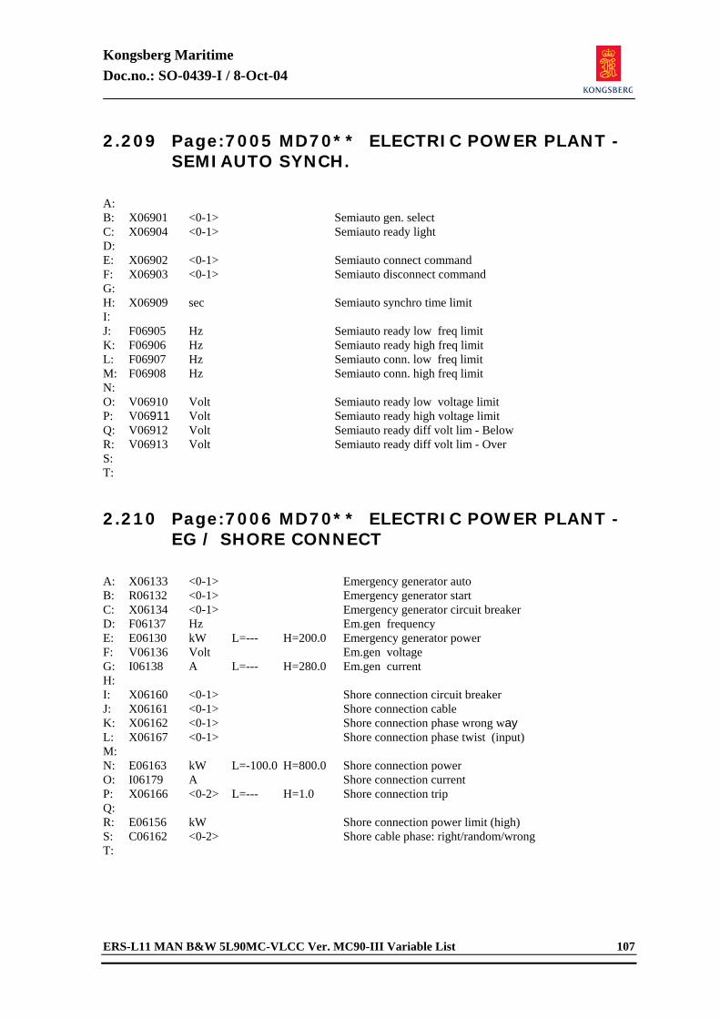
Kongsberg Maritime Doc.no.: SO-0439-I / 8-Oct-04
ERS-L11 MAN B&W 5L90MC-VLCC Ver. MC90-III Variable List 107
2.209 Page:7005 MD70** ELECTRIC POWER PLANT - SEMIAUTO SYNCH.
A: B: X06901 <0-1> Semiauto gen. select C: X06904 <0-1> Semiauto ready light D: E: X06902 <0-1> Semiauto connect command F: X06903 <0-1> Semiauto disconnect command G: H: X06909 sec Semiauto synchro time limit I: J: F06905 Hz Semiauto ready low freq limit K: F06906 Hz Semiauto ready high freq limit L: F06907 Hz Semiauto conn. low freq limit M: F06908 Hz Semiauto conn. high freq limit N: O: V06910 Volt Semiauto ready low voltage limit P: V06911 Volt Semiauto ready high voltage limit Q: V06912 Volt Semiauto ready diff volt lim - Below R: V06913 Volt Semiauto ready diff volt lim - Over S: T: 2.210 Page:7006 MD70** ELECTRIC POWER PLANT -
EG / SHORE CONNECT
A: X06133 <0-1> Emergency generator auto B: R06132 <0-1> Emergency generator start C: X06134 <0-1> Emergency generator circuit breaker D: F06137 Hz Em.gen frequency E: E06130 kW L=--- H=200.0 Emergency generator power F: V06136 Volt Em.gen voltage G: I06138 A L=--- H=280.0 Em.gen current H: I: X06160 <0-1> Shore connection circuit breaker J: X06161 <0-1> Shore connection cable K: X06162 <0-1> Shore connection phase wrong way L: X06167 <0-1> Shore connection phase twist (input) M: N: E06163 kW L=-100.0 H=800.0 Shore connection power O: I06179 A Shore connection current P: X06166 <0-2> L=--- H=1.0 Shore connection trip Q: R: E06156 kW Shore connection power limit (high) S: C06162 <0-2> Shore cable phase: right/random/wrong T:
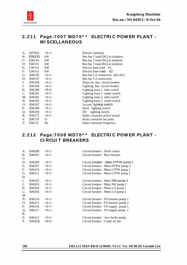
Kongsberg Maritime Doc.no.: SO-0439-I / 8-Oct-04
108 ERS-L11 MAN B&W 5L90MC-VLCC Ver. MC90-III Variable List
2.211 Page:7007 MD70** ELECTRIC POWER PLANT - MISCELLANEOUS
A: X07032 <0-1> Electric isolation B: E06153 kW Bus bar 1 load (DG) at isolation C: E06154 kW Bus bar 2 load (SG) at isolation D: E06155 kW Bus bar 3 load (EG) at isolation E: C06151 kW Electric base load - S1 F: C06152 kW Electric base load - S2 G: X06150 <0-1> Bus bar 1/2 connection (DG/SG) H: X06147 <0-1> Bus bar 1/3 connection I: X06168 <0-1> None ess. bus circuit breaker J: X06169 <0-1> Lighting bus circuit breaker K: X06180 <0-1> Lighting trans 1 inlet switch L: X06181 <0-1> Lighting trans 1 outlet switch M: X06182 <0-1> Lighting trans 2 inlet switch N: X06183 <0-1> Lighting trans 2 outlet switch O: X06187 <0-1> Accom lighting switch P: X06188 <0-1> Deck lighting switch Q: X06189 <0-1> ER lighting switch R: X06171 <0-1> Static converter active switch S: Z06170 % Static converter set point T: F06172 Hz Static converter frequency 2.212 Page:7008 MD70** ELECTRIC POWER PLANT -
CIRCUIT BREAKERS
A: X06200 <0-1> Circuit breaker - Deck cranes B: X06201 <0-1> Circuit breaker - Bow thruster C: D: X06206 <0-1> Circuit breaker - Main HTFW pump 1 E: X06207 <0-1> Circuit breaker - Main HTFW pump 2 F: X06210 <0-1> Circuit breaker - Main LTFW pump 1 G: X06211 <0-1> Circuit breaker - Main LTFW pump 2 H: I: X06202 <0-1> Circuit breaker - Main SW pump 1 J: X06203 <0-1> Circuit breaker - Main SW pump 2 K: X06204 <0-1> Circuit breaker - Main LO pump 1 L: X06205 <0-1> Circuit breaker - Main LO pump 2 M: N: X06214 <0-1> Circuit breaker - FO booster pump 1 O: X06215 <0-1> Circuit breaker - FO booster pump 2 P: X06216 <0-1> Circuit breaker - FO supply pump 1 Q: X06217 <0-1> Circuit breaker - FO supply pump 2 R: S: X06212 <0-1> Circuit breaker - Aux feedw pump T: X06213 <0-1> Circuit breaker - Comb air fan
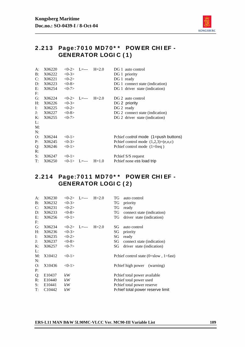
Kongsberg Maritime Doc.no.: SO-0439-I / 8-Oct-04
ERS-L11 MAN B&W 5L90MC-VLCC Ver. MC90-III Variable List 109
2.213 Page:7010 MD70** POWER CHIEF - GENERATOR LOGIC (1)
A: X06220 <0-2> L=--- H=2.0 DG 1 auto control B: X06222 <0-3> DG 1 priority C: X06221 <0-2> DG 1 ready D: X06223 <0-8> DG 1 connect state (indication) E: X06254 <0-7> DG 1 driver state (indication) F: G: X06224 <0-2> L=--- H=2.0 DG 2 auto control H: X06226 <0-3> DG 2 priority I: X06225 <0-2> DG 2 ready J: X06227 <0-8> DG 2 connect state (indication) K: X06255 <0-7> DG 2 driver state (indication) L: M: N: O: X06244 <0-1> Pchief control mode (1=push buttons) P: X06245 <0-3> Pchief control mode (1,2,3)=(e,o,c) Q: X06246 <0-1> Pchief control mode (1=freq ) R: S: X06247 <0-1> Pchief S/S request T: X06250 <0-1> L=--- H=1.0 Pchief none ess load trip 2.214 Page:7011 MD70** POWER CHIEF -
GENERATOR LOGIC (2)
A: X06230 <0-2> L=--- H=2.0 TG auto control B: X06232 <0-3> TG priority C: X06231 <0-2> TG ready D: X06233 <0-8> TG connect state (indication) E: X06256 <0-1> TG driver state (indication) F: G: X06234 <0-2> L=--- H=2.0 SG auto control H: X06236 <0-3> SG priority I: X06235 <0-2> SG ready J: X06237 <0-8> SG connect state (indication) K: X06257 <0-7> SG driver state (indication) L: M: X10412 <0-1> Pchief control state (0=slow , 1=fast) N: O: X10436 <0-1> Pchief high power (warning) P: Q: E10437 kW Pchief total power available R: E10440 kW Pchief total power used S: E10441 kW Pchief total power reserve T: C10442 kW Pchief total power reserve limit
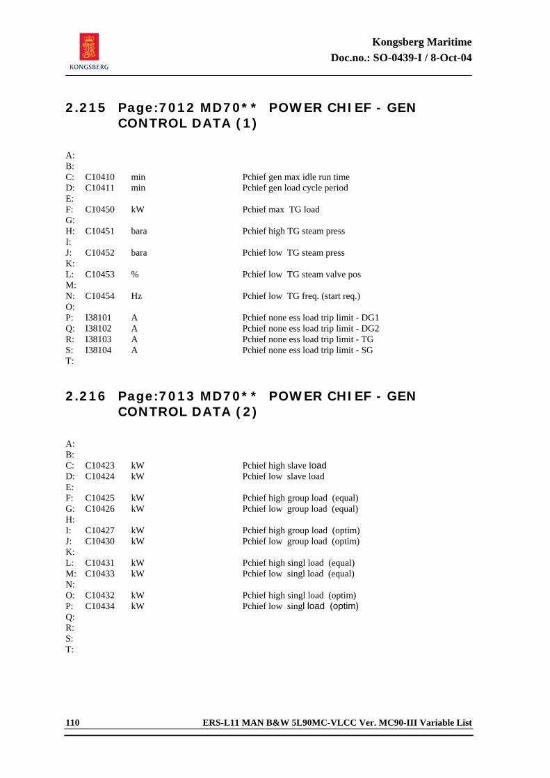
Kongsberg Maritime Doc.no.: SO-0439-I / 8-Oct-04
110 ERS-L11 MAN B&W 5L90MC-VLCC Ver. MC90-III Variable List
2.215 Page:7012 MD70** POWER CHIEF - GEN CONTROL DATA (1)
A: B: C: C10410 min Pchief gen max idle run time D: C10411 min Pchief gen load cycle period E: F: C10450 kW Pchief max TG load G: H: C10451 bara Pchief high TG steam press I: J: C10452 bara Pchief low TG steam press K: L: C10453 % Pchief low TG steam valve pos M: N: C10454 Hz Pchief low TG freq. (start req.) O: P: I38101 A Pchief none ess load trip limit - DG1 Q: I38102 A Pchief none ess load trip limit - DG2 R: I38103 A Pchief none ess load trip limit - TG S: I38104 A Pchief none ess load trip limit - SG T: 2.216 Page:7013 MD70** POWER CHIEF - GEN
CONTROL DATA (2)
A: B: C: C10423 kW Pchief high slave load D: C10424 kW Pchief low slave load E: F: C10425 kW Pchief high group load (equal) G: C10426 kW Pchief low group load (equal) H: I: C10427 kW Pchief high group load (optim) J: C10430 kW Pchief low group load (optim) K: L: C10431 kW Pchief high singl load (equal) M: C10433 kW Pchief low singl load (equal) N: O: C10432 kW Pchief high singl load (optim) P: C10434 kW Pchief low singl load (optim) Q: R: S: T:
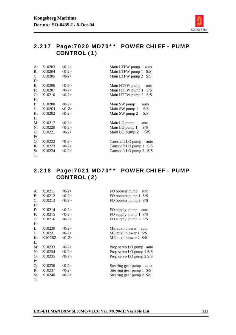
Kongsberg Maritime Doc.no.: SO-0439-I / 8-Oct-04
ERS-L11 MAN B&W 5L90MC-VLCC Ver. MC90-III Variable List 111
2.217 Page:7020 MD70** POWER CHIEF - PUMP CONTROL (1)
A: X10203 <0-2> Main LTFW pump auto B: X10204 <0-2> Main LTFW pump 1 S/S C: X10205 <0-2> Main LTFW pump 2 S/S D: E: X10206 <0-2> Main HTFW pump auto F: X10207 <0-2> Main HTFW pump 1 S/S G: X10210 <0-2> Main HTFW pump 2 S/S H: I: X10200 <0-2> Main SW pump auto J: X10201 <0-2> Main SW pump 1 S/S K: X10202 <0-2> Main SW pump 2 S/S L: M: X10217 <0-2> Main LO pump auto N: X10220 <0-2> Main LO pump 1 S/S O: X10221 <0-2> Main LO pump 2 S/S P: Q: X10222 <0-2> Camshaft LO pump auto R: X10223 <0-2> Camshaft LO pump 1 S/S S: X10224 <0-2> Camshaft LO pump 2 S/S T: 2.218 Page:7021 MD70** POWER CHIEF - PUMP
CONTROL (2)
A: X10211 <0-2> FO booster pump auto B: X10212 <0-2> FO booster pump 1 S/S C: X10213 <0-2> FO booster pump 2 S/S D: E: X10214 <0-2> FO supply pump auto F: X10215 <0-2> FO supply pump 1 S/S G: X10216 <0-2> FO supply pump 2 S/S H: I: X10230 <0-2> ME auxil blower auto J: X10231 <0-2> ME auxil blower 1 S/S K: X10232 <0-2> ME auxil blower 2 S/S L: M: X10233 <0-2> Prop servo LO pump auto N: X10234 <0-2> Prop servo LO pump 1 S/S O: X10235 <0-2> Prop servo LO pump 2 S/S P: Q: X10236 <0-2> Steering gear pump auto R: X10237 <0-2> Steering gear pump 1 S/S S: X10240 <0-2> Steering gear pump 2 S/S T:
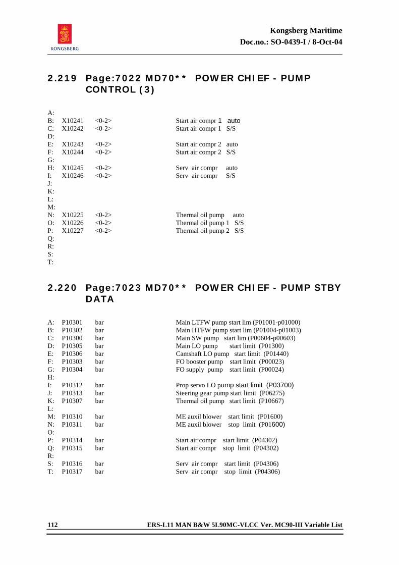
Kongsberg Maritime Doc.no.: SO-0439-I / 8-Oct-04
112 ERS-L11 MAN B&W 5L90MC-VLCC Ver. MC90-III Variable List
2.219 Page:7022 MD70** POWER CHIEF - PUMP CONTROL (3)
A: B: X10241 <0-2> Start air compr 1 auto C: X10242 <0-2> Start air compr 1 S/S D: E: X10243 <0-2> Start air compr 2 auto F: X10244 <0-2> Start air compr 2 S/S G: H: X10245 <0-2> Serv air compr auto I: X10246 <0-2> Serv air compr S/S J: K: L: M: N: X10225 <0-2> Thermal oil pump auto O: X10226 <0-2> Thermal oil pump 1 S/S P: X10227 <0-2> Thermal oil pump 2 S/S Q: R: S: T: 2.220 Page:7023 MD70** POWER CHIEF - PUMP STBY
DATA
A: P10301 bar Main LTFW pump start lim (P01001-p01000) B: P10302 bar Main HTFW pump start lim (P01004-p01003) C: P10300 bar Main SW pump start lim (P00604-p00603) D: P10305 bar Main LO pump start limit (P01300) E: P10306 bar Camshaft LO pump start limit (P01440) F: P10303 bar FO booster pump start limit (P00023) G: P10304 bar FO supply pump start limit (P00024) H: I: P10312 bar Prop servo LO pump start limit (P03700) J: P10313 bar Steering gear pump start limit (P06275) K: P10307 bar Thermal oil pump start limit (P10667) L: M: P10310 bar ME auxil blower start limit (P01600) N: P10311 bar ME auxil blower stop limit (P01600) O: P: P10314 bar Start air compr start limit (P04302) Q: P10315 bar Start air compr stop limit (P04302) R: S: P10316 bar Serv air compr start limit (P04306) T: P10317 bar Serv air compr stop limit (P04306)
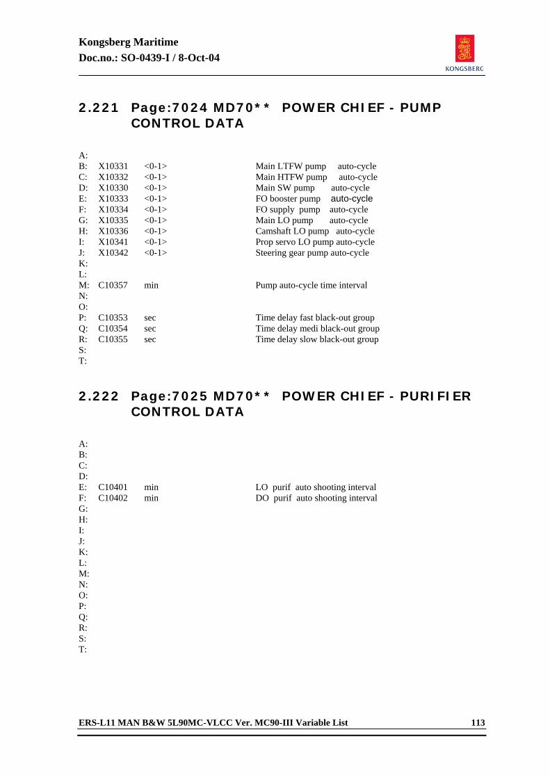
Kongsberg Maritime Doc.no.: SO-0439-I / 8-Oct-04
ERS-L11 MAN B&W 5L90MC-VLCC Ver. MC90-III Variable List 113
2.221 Page:7024 MD70** POWER CHIEF - PUMP CONTROL DATA
A: B: X10331 <0-1> Main LTFW pump auto-cycle C: X10332 <0-1> Main HTFW pump auto-cycle D: X10330 <0-1> Main SW pump auto-cycle E: X10333 <0-1> FO booster pump auto-cycle F: X10334 <0-1> FO supply pump auto-cycle G: X10335 <0-1> Main LO pump auto-cycle H: X10336 <0-1> Camshaft LO pump auto-cycle I: X10341 <0-1> Prop servo LO pump auto-cycle J: X10342 <0-1> Steering gear pump auto-cycle K: L: M: C10357 min Pump auto-cycle time interval N: O: P: C10353 sec Time delay fast black-out group Q: C10354 sec Time delay medi black-out group R: C10355 sec Time delay slow black-out group S: T: 2.222 Page:7025 MD70** POWER CHIEF - PURIFIER
CONTROL DATA
A: B: C: D: E: C10401 min LO purif auto shooting interval F: C10402 min DO purif auto shooting interval G: H: I: J: K: L: M: N: O: P: Q: R: S: T:
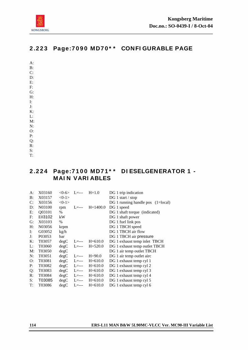
Kongsberg Maritime Doc.no.: SO-0439-I / 8-Oct-04
114 ERS-L11 MAN B&W 5L90MC-VLCC Ver. MC90-III Variable List
2.223 Page:7090 MD70** CONFIGURABLE PAGE
A: B: C: D: E: F: G: H: I: J: K: L: M: N: O: P: Q: R: S: T: 2.224 Page:7100 MD71** DIESELGENERATOR 1 -
MAIN VARIABLES
A: X03160 <0-6> L=--- H=1.0 DG 1 trip indication B: X03157 <0-1> DG 1 start / stop C: X03156 <0-1> DG 1 running handle pos (1=local) D: N03100 rpm L=--- H=1400.0 DG 1 speed E: Q03101 % DG 1 shaft torque (indicated) F: E03102 kW DG 1 shaft power G: X03103 % DG 1 fuel link pos H: N03056 krpm DG 1 TBCH speed I: G03052 kg/h DG 1 TBCH air flow J: P03053 bar DG 1 TBCH air pressure K: T03057 degC L=--- H=610.0 DG 1 exhaust temp inlet TBCH L: T03060 degC L=--- H=520.0 DG 1 exhaust temp outlet TBCH M: T03050 degC DG 1 air temp outlet TBCH N: T03051 degC L=--- H=90.0 DG 1 air temp outlet airc O: T03081 degC L=--- H=610.0 DG 1 exhaust temp cyl 1 P: T03082 degC L=--- H=610.0 DG 1 exhaust temp cyl 2 Q: T03083 degC L=--- H=610.0 DG 1 exhaust temp cyl 3 R: T03084 degC L=--- H=610.0 DG 1 exhaust temp cyl 4 S: T03085 degC L=--- H=610.0 DG 1 exhaust temp cyl 5 T: T03086 degC L=--- H=610.0 DG 1 exhaust temp cyl 6
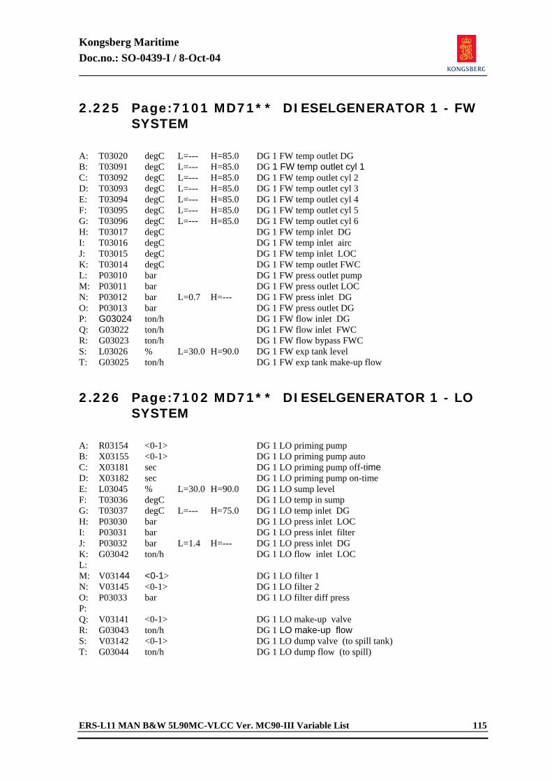
Kongsberg Maritime Doc.no.: SO-0439-I / 8-Oct-04
ERS-L11 MAN B&W 5L90MC-VLCC Ver. MC90-III Variable List 115
2.225 Page:7101 MD71** DIESELGENERATOR 1 - FW SYSTEM
A: T03020 degC L=--- H=85.0 DG 1 FW temp outlet DG B: T03091 degC L=--- H=85.0 DG 1 FW temp outlet cyl 1 C: T03092 degC L=--- H=85.0 DG 1 FW temp outlet cyl 2 D: T03093 degC L=--- H=85.0 DG 1 FW temp outlet cyl 3 E: T03094 degC L=--- H=85.0 DG 1 FW temp outlet cyl 4 F: T03095 degC L=--- H=85.0 DG 1 FW temp outlet cyl 5 G: T03096 degC L=--- H=85.0 DG 1 FW temp outlet cyl 6 H: T03017 degC DG 1 FW temp inlet DG I: T03016 degC DG 1 FW temp inlet airc J: T03015 degC DG 1 FW temp inlet LOC K: T03014 degC DG 1 FW temp outlet FWC L: P03010 bar DG 1 FW press outlet pump M: P03011 bar DG 1 FW press outlet LOC N: P03012 bar L=0.7 H=--- DG 1 FW press inlet DG O: P03013 bar DG 1 FW press outlet DG P: G03024 ton/h DG 1 FW flow inlet DG Q: G03022 ton/h DG 1 FW flow inlet FWC R: G03023 ton/h DG 1 FW flow bypass FWC S: L03026 % L=30.0 H=90.0 DG 1 FW exp tank level T: G03025 ton/h DG 1 FW exp tank make-up flow 2.226 Page:7102 MD71** DIESELGENERATOR 1 - LO
SYSTEM
A: R03154 <0-1> DG 1 LO priming pump B: X03155 <0-1> DG 1 LO priming pump auto C: X03181 sec DG 1 LO priming pump off-time D: X03182 sec DG 1 LO priming pump on-time E: L03045 % L=30.0 H=90.0 DG 1 LO sump level F: T03036 degC DG 1 LO temp in sump G: T03037 degC L=--- H=75.0 DG 1 LO temp inlet DG H: P03030 bar DG 1 LO press inlet LOC I: P03031 bar DG 1 LO press inlet filter J: P03032 bar L=1.4 H=--- DG 1 LO press inlet DG K: G03042 ton/h DG 1 LO flow inlet LOC L: M: V03144 <0-1> DG 1 LO filter 1 N: V03145 <0-1> DG 1 LO filter 2 O: P03033 bar DG 1 LO filter diff press P: Q: V03141 <0-1> DG 1 LO make-up valve R: G03043 ton/h DG 1 LO make-up flow S: V03142 <0-1> DG 1 LO dump valve (to spill tank) T: G03044 ton/h DG 1 LO dump flow (to spill)
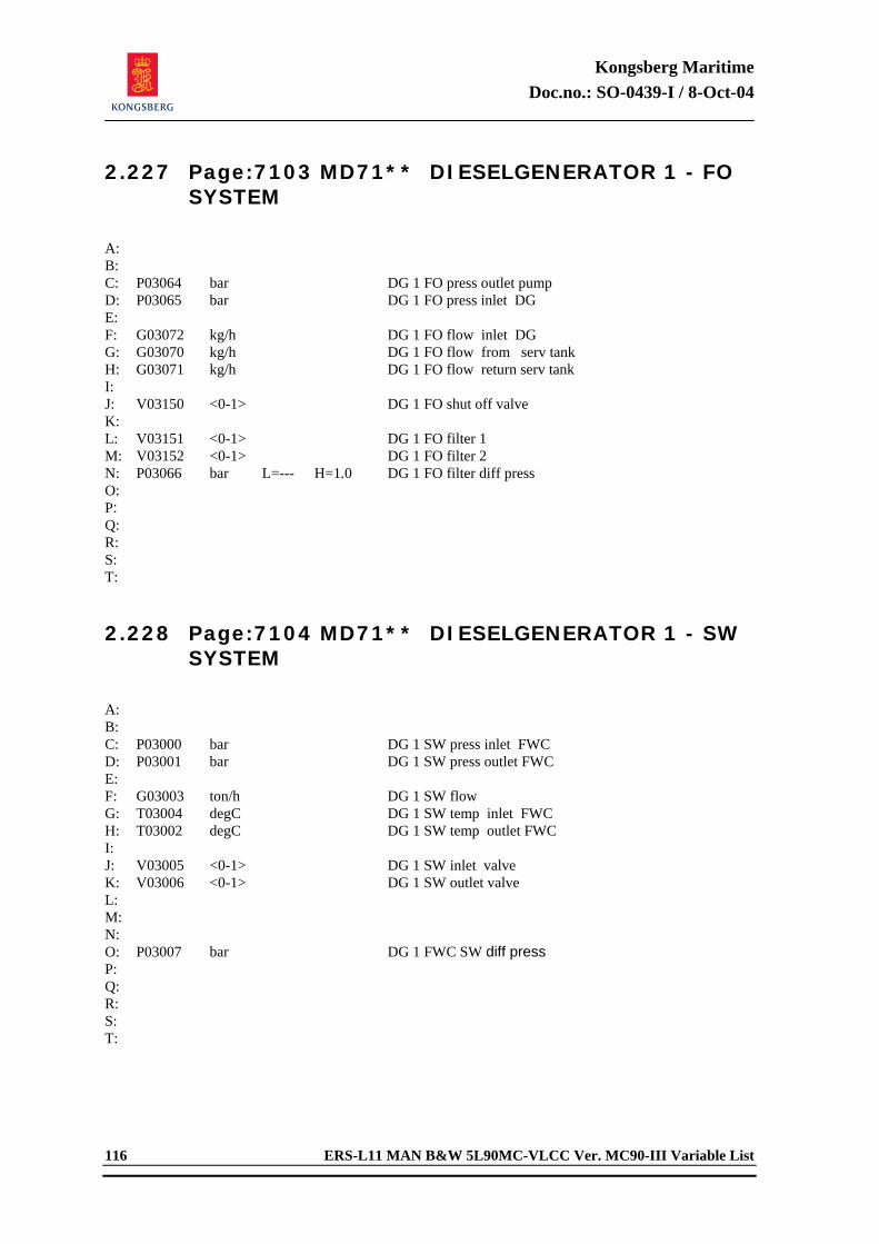
Kongsberg Maritime Doc.no.: SO-0439-I / 8-Oct-04
116 ERS-L11 MAN B&W 5L90MC-VLCC Ver. MC90-III Variable List
2.227 Page:7103 MD71** DIESELGENERATOR 1 - FO SYSTEM
A: B: C: P03064 bar DG 1 FO press outlet pump D: P03065 bar DG 1 FO press inlet DG E: F: G03072 kg/h DG 1 FO flow inlet DG G: G03070 kg/h DG 1 FO flow from serv tank H: G03071 kg/h DG 1 FO flow return serv tank I: J: V03150 <0-1> DG 1 FO shut off valve K: L: V03151 <0-1> DG 1 FO filter 1 M: V03152 <0-1> DG 1 FO filter 2 N: P03066 bar L=--- H=1.0 DG 1 FO filter diff press O: P: Q: R: S: T: 2.228 Page:7104 MD71** DIESELGENERATOR 1 - SW
SYSTEM
A: B: C: P03000 bar DG 1 SW press inlet FWC D: P03001 bar DG 1 SW press outlet FWC E: F: G03003 ton/h DG 1 SW flow G: T03004 degC DG 1 SW temp inlet FWC H: T03002 degC DG 1 SW temp outlet FWC I: J: V03005 <0-1> DG 1 SW inlet valve K: V03006 <0-1> DG 1 SW outlet valve L: M: N: O: P03007 bar DG 1 FWC SW diff press P: Q: R: S: T:
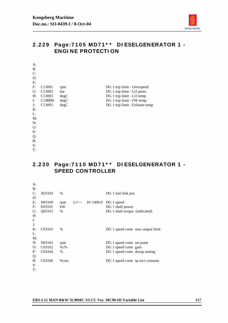
Kongsberg Maritime Doc.no.: SO-0439-I / 8-Oct-04
ERS-L11 MAN B&W 5L90MC-VLCC Ver. MC90-III Variable List 117
2.229 Page:7105 MD71** DIESELGENERATOR 1 - ENGINE PROTECTION
A: B: C: D: E: F: C13001 rpm DG 1 trip limit - Overspeed G: C13002 bar DG 1 trip limit - LO press H: C13003 degC DG 1 trip limit - LO temp I: C13004 degC DG 1 trip limit - FW temp J: C13005 degC DG 1 trip limit - Exhaust temp K: L: M: N: O: P: Q: R: S: T: 2.230 Page:7110 MD71** DIESELGENERATOR 1 -
SPEED CONTROLLER
A: B: C: X03103 % DG 1 fuel link pos D: E: N03100 rpm L=--- H=1400.0 DG 1 speed F: E03102 kW DG 1 shaft power G: Q03101 % DG 1 shaft torque (indicated) H: I: J: K: C03163 % DG 1 speed contr max output limit L: M: N: N03161 rpm DG 1 speed contr set point O: C03162 %/% DG 1 speed contr gain P: C03164 % DG 1 speed contr droop setting Q: R: C03166 %/sec DG 1 speed contr sp incr constant S: T:
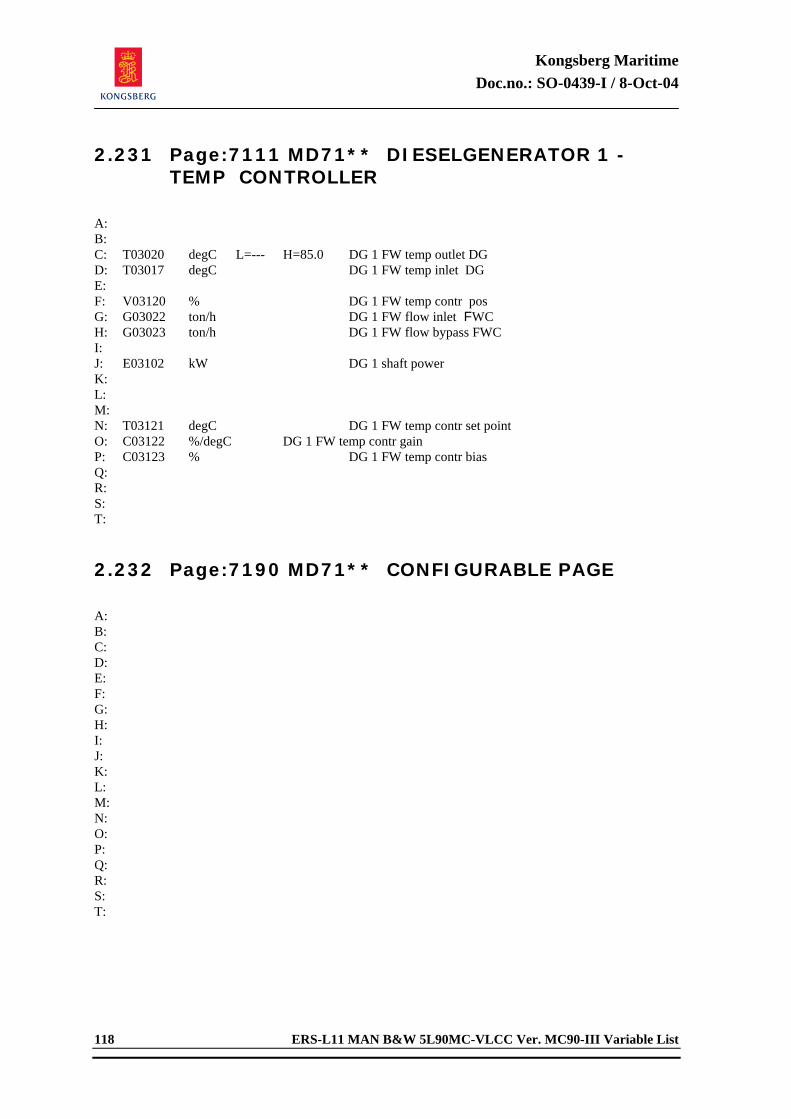
Kongsberg Maritime Doc.no.: SO-0439-I / 8-Oct-04
118 ERS-L11 MAN B&W 5L90MC-VLCC Ver. MC90-III Variable List
2.231 Page:7111 MD71** DIESELGENERATOR 1 - TEMP CONTROLLER
A: B: C: T03020 degC L=--- H=85.0 DG 1 FW temp outlet DG D: T03017 degC DG 1 FW temp inlet DG E: F: V03120 % DG 1 FW temp contr pos G: G03022 ton/h DG 1 FW flow inlet FWC H: G03023 ton/h DG 1 FW flow bypass FWC I: J: E03102 kW DG 1 shaft power K: L: M: N: T03121 degC DG 1 FW temp contr set point O: C03122 %/degC DG 1 FW temp contr gain P: C03123 % DG 1 FW temp contr bias Q: R: S: T: 2.232 Page:7190 MD71** CONFIGURABLE PAGE
A: B: C: D: E: F: G: H: I: J: K: L: M: N: O: P: Q: R: S: T:
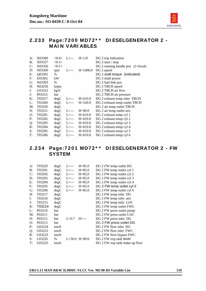
Kongsberg Maritime Doc.no.: SO-0439-I / 8-Oct-04
ERS-L11 MAN B&W 5L90MC-VLCC Ver. MC90-III Variable List 119
2.233 Page:7200 MD72** DIESELGENERATOR 2 - MAIN VARIABLES
A: X03360 <0-6> L=--- H=1.0 DG 2 trip indication B: X03357 <0-1> DG 2 start / stop C: X03356 <0-1> DG 2 running handle pos (1=local) D: N03300 rpm L=--- H=1400.0 DG 2 speed E: Q03301 % DG 2 shaft torque (indicated) F: E03302 kW DG 2 shaft power G: X03303 % DG 2 fuel link pos H: N03256 krpm DG 2 TBCH speed I: G03252 kg/h DG 2 TBCH air flow J: P03253 bar DG 2 TBCH air pressure K: T03257 degC L=--- H=610.0 DG 2 exhaust temp inlet TBCH L: T03260 degC L=--- H=520.0 DG 2 exhaust temp outlet TBCH M: T03250 degC DG 2 air temp outlet TBCH N: T03251 degC L=--- H=90.0 DG 2 air temp outlet airc O: T03281 degC L=--- H=610.0 DG 2 exhaust temp cyl 1 P: T03282 degC L=--- H=610.0 DG 2 exhaust temp cyl 2 Q: T03283 degC L=--- H=610.0 DG 2 exhaust temp cyl 3 R: T03284 degC L=--- H=610.0 DG 2 exhaust temp cyl 4 S: T03285 degC L=--- H=610.0 DG 2 exhaust temp cyl 5 T: T03286 degC L=--- H=610.0 DG 2 exhaust temp cyl 6 2.234 Page:7201 MD72** DIESELGENERATOR 2 - FW
SYSTEM
A: T03220 degC L=--- H=85.0 DG 2 FW temp outlet DG B: T03291 degC L=--- H=85.0 DG 2 FW temp outlet cyl 1 C: T03292 degC L=--- H=85.0 DG 2 FW temp outlet cyl 2 D: T03293 degC L=--- H=85.0 DG 2 FW temp outlet cyl 3 E: T03294 degC L=--- H=85.0 DG 2 FW temp outlet cyl 4 F: T03295 degC L=--- H=85.0 DG 2 FW temp outlet cyl 5 G: T03296 degC L=--- H=85.0 DG 2 FW temp outlet cyl 6 H: T03217 degC DG 2 FW temp inlet DG I: T03216 degC DG 2 FW temp inlet airc J: T03215 degC DG 2 FW temp inlet LOC K: T03214 degC DG 2 FW temp outlet FWC L: P03210 bar DG 2 FW press outlet pump M: P03211 bar DG 2 FW press outlet LOC N: P03212 bar L=0.7 H=--- DG 2 FW press inlet DG O: P03213 bar DG 2 FW press outlet DG P: G03224 ton/h DG 2 FW flow inlet DG Q: G03222 ton/h DG 2 FW flow inlet FWC R: G03223 ton/h DG 2 FW flow bypass FWC S: L03226 % L=30.0 H=90.0 DG 2 FW exp tank level T: G03225 ton/h DG 2 FW exp tank make-up flow
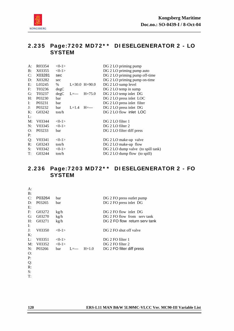
Kongsberg Maritime Doc.no.: SO-0439-I / 8-Oct-04
120 ERS-L11 MAN B&W 5L90MC-VLCC Ver. MC90-III Variable List
2.235 Page:7202 MD72** DIESELGENERATOR 2 - LO SYSTEM
A: R03354 <0-1> DG 2 LO priming pump B: X03355 <0-1> DG 2 LO priming pump auto C: X03281 sec DG 2 LO priming pump off-time D: X03282 sec DG 2 LO priming pump on-time E: L03245 % L=30.0 H=90.0 DG 2 LO sump level F: T03236 degC DG 2 LO temp in sump G: T03237 degC L=--- H=75.0 DG 2 LO temp inlet DG H: P03230 bar DG 2 LO press inlet LOC I: P03231 bar DG 2 LO press inlet filter J: P03232 bar L=1.4 H=--- DG 2 LO press inlet DG K: G03242 ton/h DG 2 LO flow inlet LOC L: M: V03344 <0-1> DG 2 LO filter 1 N: V03345 <0-1> DG 2 LO filter 2 O: P03233 bar DG 2 LO filter diff press P: Q: V03341 <0-1> DG 2 LO make-up valve R: G03243 ton/h DG 2 LO make-up flow S: V03342 <0-1> DG 2 LO dump valve (to spill tank) T: G03244 ton/h DG 2 LO dump flow (to spill) 2.236 Page:7203 MD72** DIESELGENERATOR 2 - FO
SYSTEM
A: B: C: P03264 bar DG 2 FO press outlet pump D: P03265 bar DG 2 FO press inlet DG E: F: G03272 kg/h DG 2 FO flow inlet DG G: G03270 kg/h DG 2 FO flow from serv tank H: G03271 kg/h DG 2 FO flow return serv tank I: J: V03350 <0-1> DG 2 FO shut off valve K: L: V03351 <0-1> DG 2 FO filter 1 M: V03352 <0-1> DG 2 FO filter 2 N: P03266 bar L=--- H=1.0 DG 2 FO filter diff press O: P: Q: R: S: T:
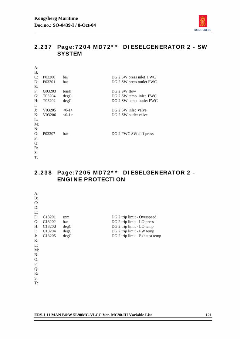
Kongsberg Maritime Doc.no.: SO-0439-I / 8-Oct-04
ERS-L11 MAN B&W 5L90MC-VLCC Ver. MC90-III Variable List 121
2.237 Page:7204 MD72** DIESELGENERATOR 2 - SW SYSTEM
A: B: C: P03200 bar DG 2 SW press inlet FWC D: P03201 bar DG 2 SW press outlet FWC E: F: G03203 ton/h DG 2 SW flow G: T03204 degC DG 2 SW temp inlet FWC H: T03202 degC DG 2 SW temp outlet FWC I: J: V03205 <0-1> DG 2 SW inlet valve K: V03206 <0-1> DG 2 SW outlet valve L: M: N: O: P03207 bar DG 2 FWC SW diff press P: Q: R: S: T: 2.238 Page:7205 MD72** DIESELGENERATOR 2 -
ENGINE PROTECTION
A: B: C: D: E: F: C13201 rpm DG 2 trip limit - Overspeed G: C13202 bar DG 2 trip limit - LO press H: C13203 degC DG 2 trip limit - LO temp I: C13204 degC DG 2 trip limit - FW temp J: C13205 degC DG 2 trip limit - Exhaust temp K: L: M: N: O: P: Q: R: S: T:
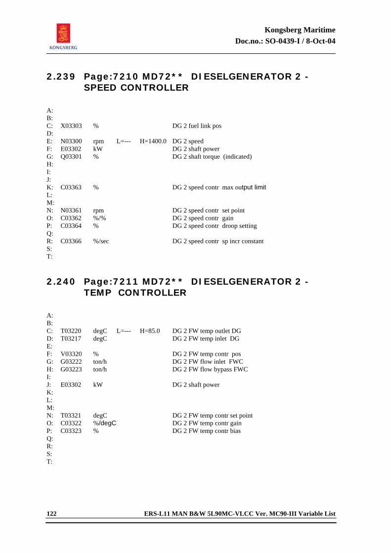
Kongsberg Maritime Doc.no.: SO-0439-I / 8-Oct-04
122 ERS-L11 MAN B&W 5L90MC-VLCC Ver. MC90-III Variable List
2.239 Page:7210 MD72** DIESELGENERATOR 2 - SPEED CONTROLLER
A: B: C: X03303 % DG 2 fuel link pos D: E: N03300 rpm L=--- H=1400.0 DG 2 speed F: E03302 kW DG 2 shaft power G: Q03301 % DG 2 shaft torque (indicated) H: I: J: K: C03363 % DG 2 speed contr max output limit L: M: N: N03361 rpm DG 2 speed contr set point O: C03362 %/% DG 2 speed contr gain P: C03364 % DG 2 speed contr droop setting Q: R: C03366 %/sec DG 2 speed contr sp incr constant S: T: 2.240 Page:7211 MD72** DIESELGENERATOR 2 -
TEMP CONTROLLER
A: B: C: T03220 degC L=--- H=85.0 DG 2 FW temp outlet DG D: T03217 degC DG 2 FW temp inlet DG E: F: V03320 % DG 2 FW temp contr pos G: G03222 ton/h DG 2 FW flow inlet FWC H: G03223 ton/h DG 2 FW flow bypass FWC I: J: E03302 kW DG 2 shaft power K: L: M: N: T03321 degC DG 2 FW temp contr set point O: C03322 %/degC DG 2 FW temp contr gain P: C03323 % DG 2 FW temp contr bias Q: R: S: T:
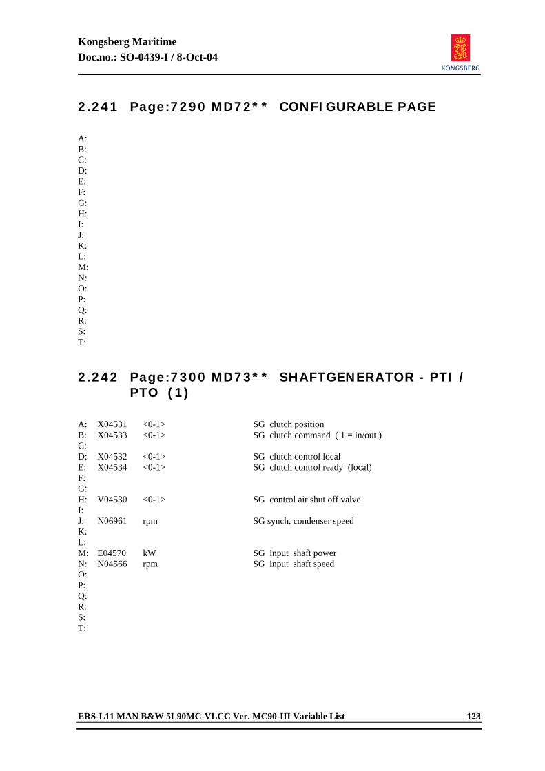
Kongsberg Maritime Doc.no.: SO-0439-I / 8-Oct-04
ERS-L11 MAN B&W 5L90MC-VLCC Ver. MC90-III Variable List 123
2.241 Page:7290 MD72** CONFIGURABLE PAGE
A: B: C: D: E: F: G: H: I: J: K: L: M: N: O: P: Q: R: S: T: 2.242 Page:7300 MD73** SHAFTGENERATOR - PTI /
PTO (1)
A: X04531 <0-1> SG clutch position B: X04533 <0-1> SG clutch command ( 1 = in/out ) C: D: X04532 <0-1> SG clutch control local E: X04534 <0-1> SG clutch control ready (local) F: G: H: V04530 <0-1> SG control air shut off valve I: J: N06961 rpm SG synch. condenser speed K: L: M: E04570 kW SG input shaft power N: N04566 rpm SG input shaft speed O: P: Q: R: S: T:
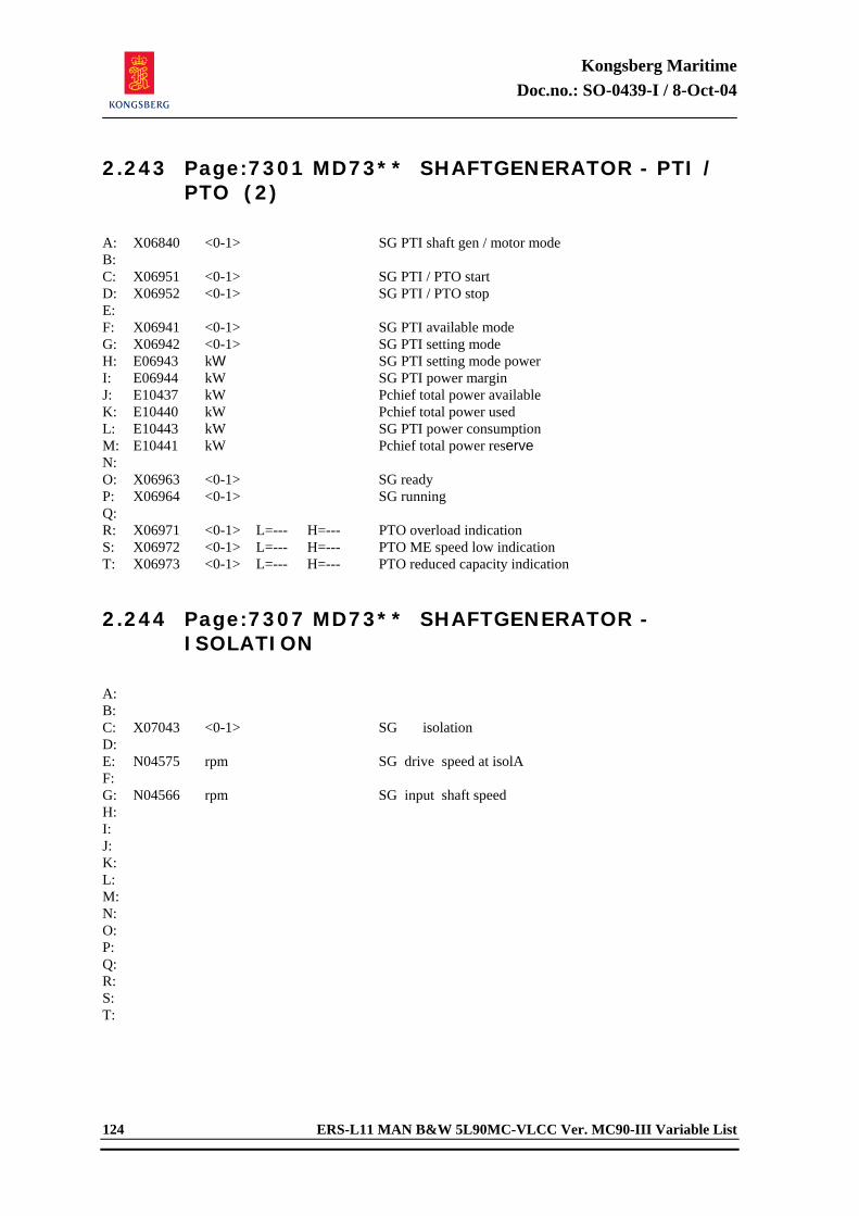
Kongsberg Maritime Doc.no.: SO-0439-I / 8-Oct-04
124 ERS-L11 MAN B&W 5L90MC-VLCC Ver. MC90-III Variable List
2.243 Page:7301 MD73** SHAFTGENERATOR - PTI / PTO (2)
A: X06840 <0-1> SG PTI shaft gen / motor mode B: C: X06951 <0-1> SG PTI / PTO start D: X06952 <0-1> SG PTI / PTO stop E: F: X06941 <0-1> SG PTI available mode G: X06942 <0-1> SG PTI setting mode H: E06943 kW SG PTI setting mode power I: E06944 kW SG PTI power margin J: E10437 kW Pchief total power available K: E10440 kW Pchief total power used L: E10443 kW SG PTI power consumption M: E10441 kW Pchief total power reserve N: O: X06963 <0-1> SG ready P: X06964 <0-1> SG running Q: R: X06971 <0-1> L=--- H=--- PTO overload indication S: X06972 <0-1> L=--- H=--- PTO ME speed low indication T: X06973 <0-1> L=--- H=--- PTO reduced capacity indication 2.244 Page:7307 MD73** SHAFTGENERATOR -
ISOLATION
A: B: C: X07043 <0-1> SG isolation D: E: N04575 rpm SG drive speed at isolA F: G: N04566 rpm SG input shaft speed H: I: J: K: L: M: N: O: P: Q: R: S: T:
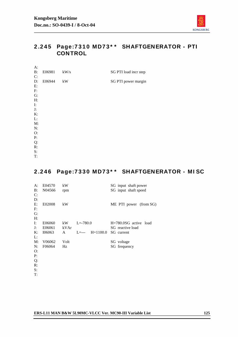
Kongsberg Maritime Doc.no.: SO-0439-I / 8-Oct-04
ERS-L11 MAN B&W 5L90MC-VLCC Ver. MC90-III Variable List 125
2.245 Page:7310 MD73** SHAFTGENERATOR - PTI CONTROL
A: B: E06981 kW/s SG PTI load incr step C: D: E06944 kW SG PTI power margin E: F: G: H: I: J: K: L: M: N: O: P: Q: R: S: T: 2.246 Page:7330 MD73** SHAFTGENERATOR - MISC
A: E04570 kW SG input shaft power B: N04566 rpm SG input shaft speed C: D: E: E02008 kW ME PTI power (from SG) F: G: H: I: E06060 kW L=-780.0 H=780.0 SG active load J: E06061 kVAr SG reactive load K: I06063 A L=--- H=1100.0 SG current L: M: V06062 Volt SG voltage N: F06064 Hz SG frequency O: P: Q: R: S: T:
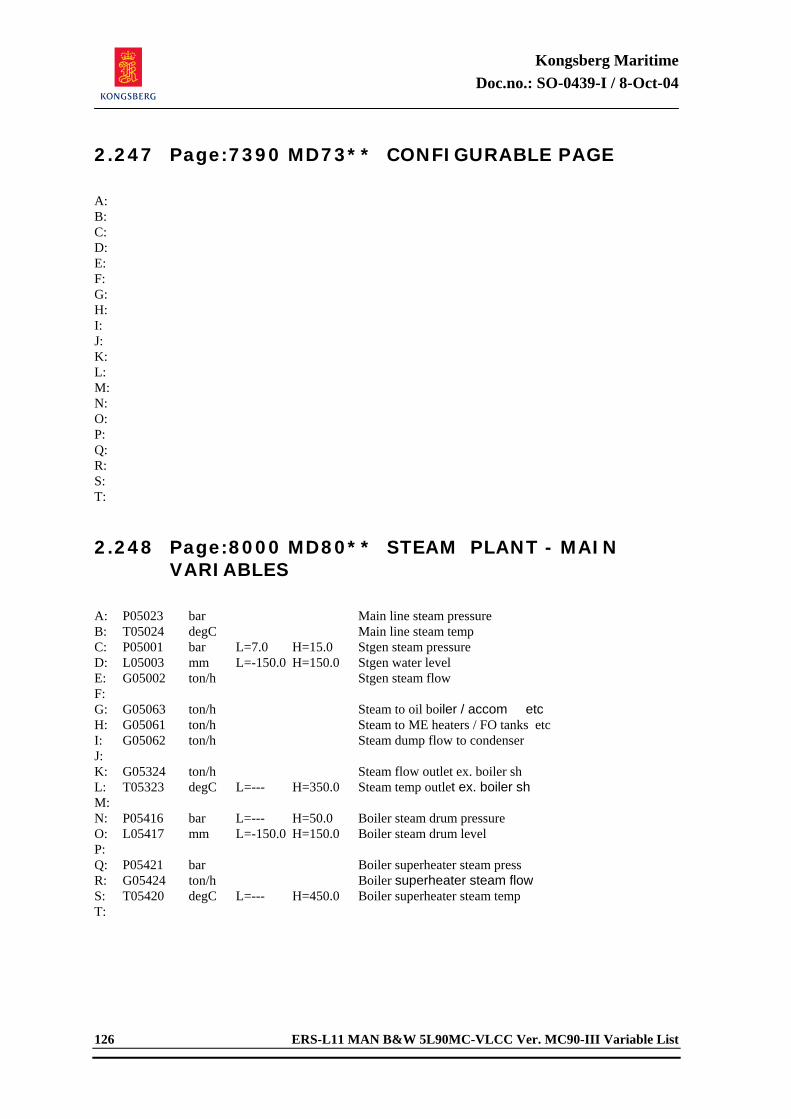
Kongsberg Maritime Doc.no.: SO-0439-I / 8-Oct-04
126 ERS-L11 MAN B&W 5L90MC-VLCC Ver. MC90-III Variable List
2.247 Page:7390 MD73** CONFIGURABLE PAGE
A: B: C: D: E: F: G: H: I: J: K: L: M: N: O: P: Q: R: S: T: 2.248 Page:8000 MD80** STEAM PLANT - MAIN
VARIABLES
A: P05023 bar Main line steam pressure B: T05024 degC Main line steam temp C: P05001 bar L=7.0 H=15.0 Stgen steam pressure D: L05003 mm L=-150.0 H=150.0 Stgen water level E: G05002 ton/h Stgen steam flow F: G: G05063 ton/h Steam to oil boiler / accom etc H: G05061 ton/h Steam to ME heaters / FO tanks etc I: G05062 ton/h Steam dump flow to condenser J: K: G05324 ton/h Steam flow outlet ex. boiler sh L: T05323 degC L=--- H=350.0 Steam temp outlet ex. boiler sh M: N: P05416 bar L=--- H=50.0 Boiler steam drum pressure O: L05417 mm L=-150.0 H=150.0 Boiler steam drum level P: Q: P05421 bar Boiler superheater steam press R: G05424 ton/h Boiler superheater steam flow S: T05420 degC L=--- H=450.0 Boiler superheater steam temp T:
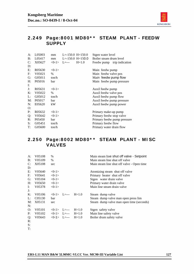
Kongsberg Maritime Doc.no.: SO-0439-I / 8-Oct-04
ERS-L11 MAN B&W 5L90MC-VLCC Ver. MC90-III Variable List 127
2.249 Page:8001 MD80** STEAM PLANT - FEEDW SUPPLY
A: L05003 mm L=-150.0 H=150.0 Stgen water level B: L05417 mm L=-150.0 H=150.0 Boiler steam drum level C: X05627 <0-1> L=--- H=1.0 Feedw pump trip indication D: E: R05630 <0-1> Main feedw pump F: V05021 % Main feedw valve pos G: G05011 ton/h Main feedw pump flow H: P05016 bar Main feedw pump pressure I: J: R05631 <0-1> Auxil feedw pump K: V05022 % Auxil feedw valve pos L: G05012 ton/h Auxil feedw pump flow M: P05017 bar Auxil feedw pump pressure N: E05620 kW Auxil feedw pump power O: P: R05632 <0-1> Primary make-up pump Q: V05642 <0-1> Primary feedw stop valve R: P05450 bar Primary feedw pump pressure S: G05451 ton/h Primary feedw flow T: G05600 ton/h Primary water drain flow 2.250 Page:8002 MD80** STEAM PLANT - MISC
VALVES
A: V05108 % Main steam line shut off valve - Setpoint B: V05109 % Main steam line shut off valve C: X05108 sec Main steam line shut off valve - Open time D: E: V05640 <0-1> Atomizing steam shut off valve F: V05641 <0-1> Primary heater shut off valve G: V05104 <0-1> Stgen water drain valve H: V05650 <0-1> Primary water drain valve I: V05378 <0-1> Main line steam drain valve J: K: V05106 <0-1> L=--- H=1.0 Steam dump valve L: C05130 bar Steam dump valve man open press lim M: X05131 sec Steam dump valve man open time (seconds) N: O: V05101 <0-1> L=--- H=1.0 Stgen safety valve P: V05102 <0-1> L=--- H=1.0 Main line safety valve Q: V05643 <0-1> L=--- H=1.0 Boiler drum safety valve R: S: T:
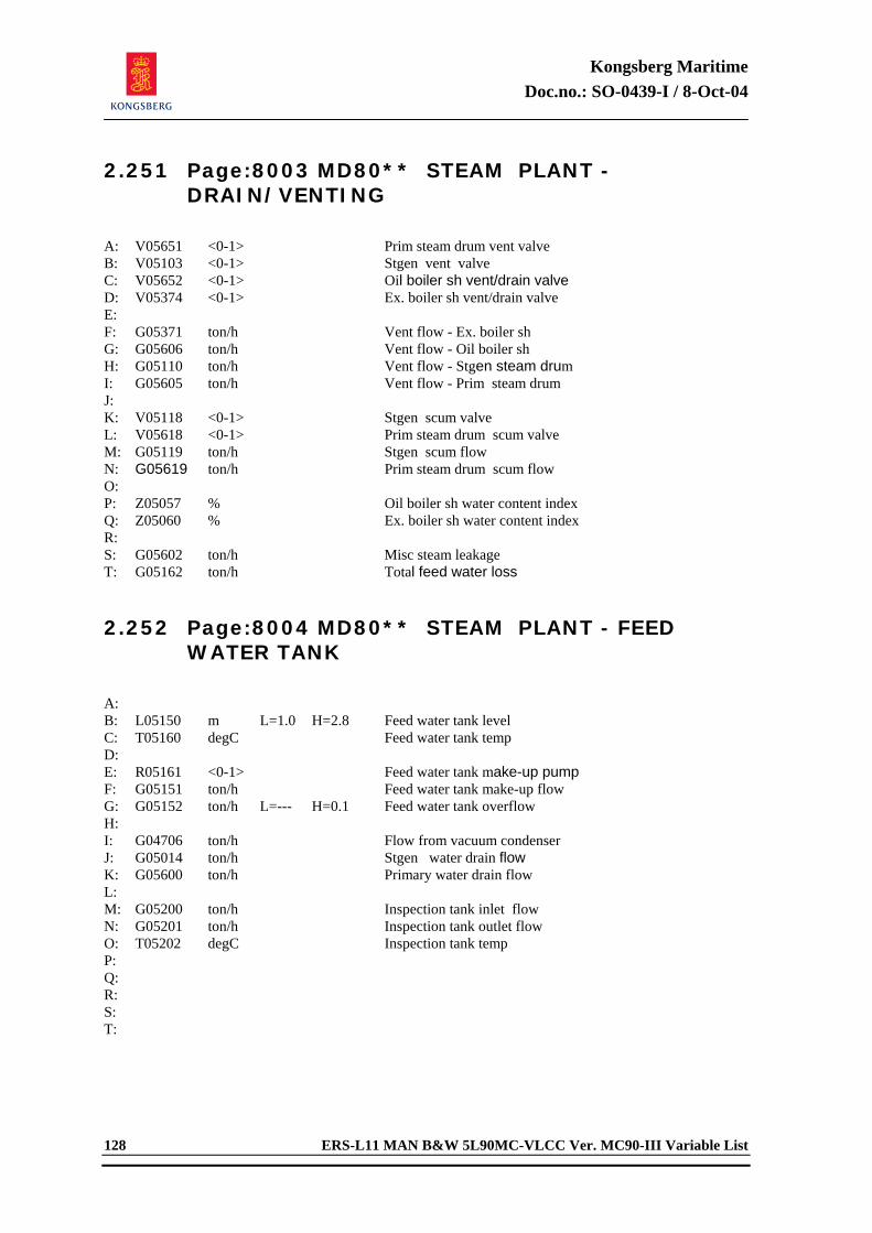
Kongsberg Maritime Doc.no.: SO-0439-I / 8-Oct-04
128 ERS-L11 MAN B&W 5L90MC-VLCC Ver. MC90-III Variable List
2.251 Page:8003 MD80** STEAM PLANT - DRAIN/VENTING
A: V05651 <0-1> Prim steam drum vent valve B: V05103 <0-1> Stgen vent valve C: V05652 <0-1> Oil boiler sh vent/drain valve D: V05374 <0-1> Ex. boiler sh vent/drain valve E: F: G05371 ton/h Vent flow - Ex. boiler sh G: G05606 ton/h Vent flow - Oil boiler sh H: G05110 ton/h Vent flow - Stgen steam drum I: G05605 ton/h Vent flow - Prim steam drum J: K: V05118 <0-1> Stgen scum valve L: V05618 <0-1> Prim steam drum scum valve M: G05119 ton/h Stgen scum flow N: G05619 ton/h Prim steam drum scum flow O: P: Z05057 % Oil boiler sh water content index Q: Z05060 % Ex. boiler sh water content index R: S: G05602 ton/h Misc steam leakage T: G05162 ton/h Total feed water loss 2.252 Page:8004 MD80** STEAM PLANT - FEED
WATER TANK
A: B: L05150 m L=1.0 H=2.8 Feed water tank level C: T05160 degC Feed water tank temp D: E: R05161 <0-1> Feed water tank make-up pump F: G05151 ton/h Feed water tank make-up flow G: G05152 ton/h L=--- H=0.1 Feed water tank overflow H: I: G04706 ton/h Flow from vacuum condenser J: G05014 ton/h Stgen water drain flow K: G05600 ton/h Primary water drain flow L: M: G05200 ton/h Inspection tank inlet flow N: G05201 ton/h Inspection tank outlet flow O: T05202 degC Inspection tank temp P: Q: R: S: T:
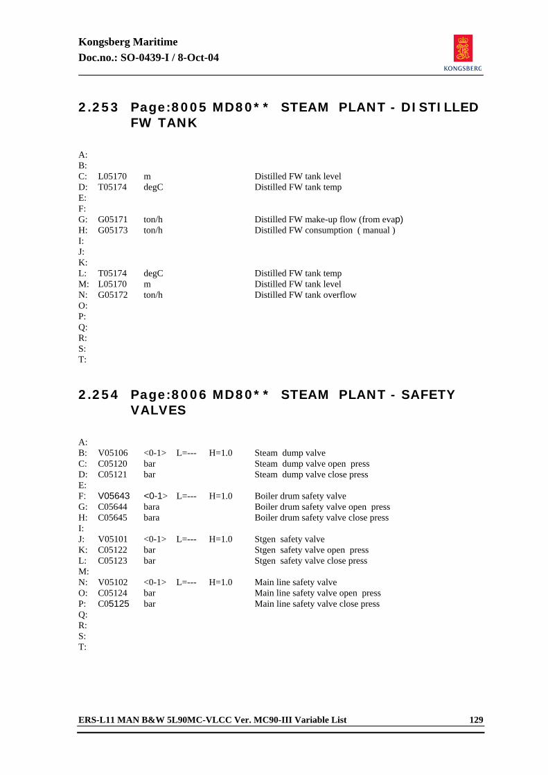
Kongsberg Maritime Doc.no.: SO-0439-I / 8-Oct-04
ERS-L11 MAN B&W 5L90MC-VLCC Ver. MC90-III Variable List 129
2.253 Page:8005 MD80** STEAM PLANT - DISTILLED FW TANK
A: B: C: L05170 m Distilled FW tank level D: T05174 degC Distilled FW tank temp E: F: G: G05171 ton/h Distilled FW make-up flow (from evap) H: G05173 ton/h Distilled FW consumption ( manual ) I: J: K: L: T05174 degC Distilled FW tank temp M: L05170 m Distilled FW tank level N: G05172 ton/h Distilled FW tank overflow O: P: Q: R: S: T: 2.254 Page:8006 MD80** STEAM PLANT - SAFETY
VALVES
A: B: V05106 <0-1> L=--- H=1.0 Steam dump valve C: C05120 bar Steam dump valve open press D: C05121 bar Steam dump valve close press E: F: V05643 <0-1> L=--- H=1.0 Boiler drum safety valve G: C05644 bara Boiler drum safety valve open press H: C05645 bara Boiler drum safety valve close press I: J: V05101 <0-1> L=--- H=1.0 Stgen safety valve K: C05122 bar Stgen safety valve open press L: C05123 bar Stgen safety valve close press M: N: V05102 <0-1> L=--- H=1.0 Main line safety valve O: C05124 bar Main line safety valve open press P: C05125 bar Main line safety valve close press Q: R: S: T:
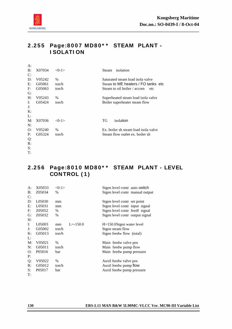
Kongsberg Maritime Doc.no.: SO-0439-I / 8-Oct-04
130 ERS-L11 MAN B&W 5L90MC-VLCC Ver. MC90-III Variable List
2.255 Page:8007 MD80** STEAM PLANT - ISOLATION
A: B: X07034 <0-1> Steam isolation C: D: V05242 % Saturated steam load isola valve E: G05061 ton/h Steam to ME heaters / FO tanks etc F: G05063 ton/h Steam to oil boiler / accom etc G: H: V05243 % Superheated steam load isola valve I: G05424 ton/h Boiler superheater steam flow J: K: L: M: X07036 <0-1> TG isolation N: O: V05240 % Ex. boiler sh steam load isola valve P: G05324 ton/h Steam flow outlet ex. boiler sh Q: R: S: T: 2.256 Page:8010 MD80** STEAM PLANT - LEVEL
CONTROL (1)
A: X05033 <0-1> Stgen level contr auto switch B: Z05034 % Stgen level contr manual output C: D: L05030 mm Stgen level contr set point E: L05031 mm Stgen level contr input signal F: Z05052 % Stgen level contr feedf signal G: Z05032 % Stgen level contr output signal H: I: L05003 mm L=-150.0 H=150.0 Stgen water level J: G05002 ton/h Stgen steam flow K: G05013 ton/h Stgen feedw flow (total) L: M: V05021 % Main feedw valve pos N: G05011 ton/h Main feedw pump flow O: P05016 bar Main feedw pump pressure P: Q: V05022 % Auxil feedw valve pos R: G05012 ton/h Auxil feedw pump flow S: P05017 bar Auxil feedw pump pressure T:
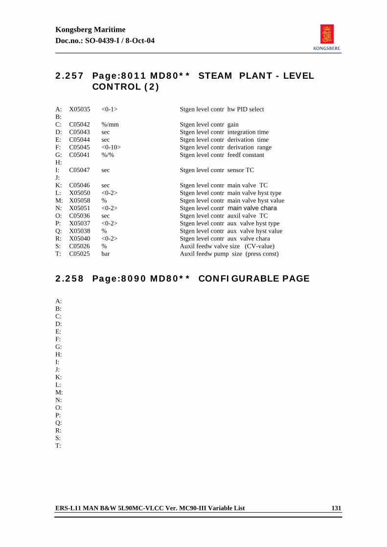
Kongsberg Maritime Doc.no.: SO-0439-I / 8-Oct-04
ERS-L11 MAN B&W 5L90MC-VLCC Ver. MC90-III Variable List 131
2.257 Page:8011 MD80** STEAM PLANT - LEVEL CONTROL (2)
A: X05035 <0-1> Stgen level contr hw PID select B: C: C05042 %/mm Stgen level contr gain D: C05043 sec Stgen level contr integration time E: C05044 sec Stgen level contr derivation time F: C05045 <0-10> Stgen level contr derivation range G: C05041 %/% Stgen level contr feedf constant H: I: C05047 sec Stgen level contr sensor TC J: K: C05046 sec Stgen level contr main valve TC L: X05050 <0-2> Stgen level contr main valve hyst type M: X05058 % Stgen level contr main valve hyst value N: X05051 <0-2> Stgen level contr main valve chara O: C05036 sec Stgen level contr auxil valve TC P: X05037 <0-2> Stgen level contr aux valve hyst type Q: X05038 % Stgen level contr aux valve hyst value R: X05040 <0-2> Stgen level contr aux valve chara S: C05026 % Auxil feedw valve size (CV-value) T: C05025 bar Auxil feedw pump size (press const) 2.258 Page:8090 MD80** CONFIGURABLE PAGE
A: B: C: D: E: F: G: H: I: J: K: L: M: N: O: P: Q: R: S: T:
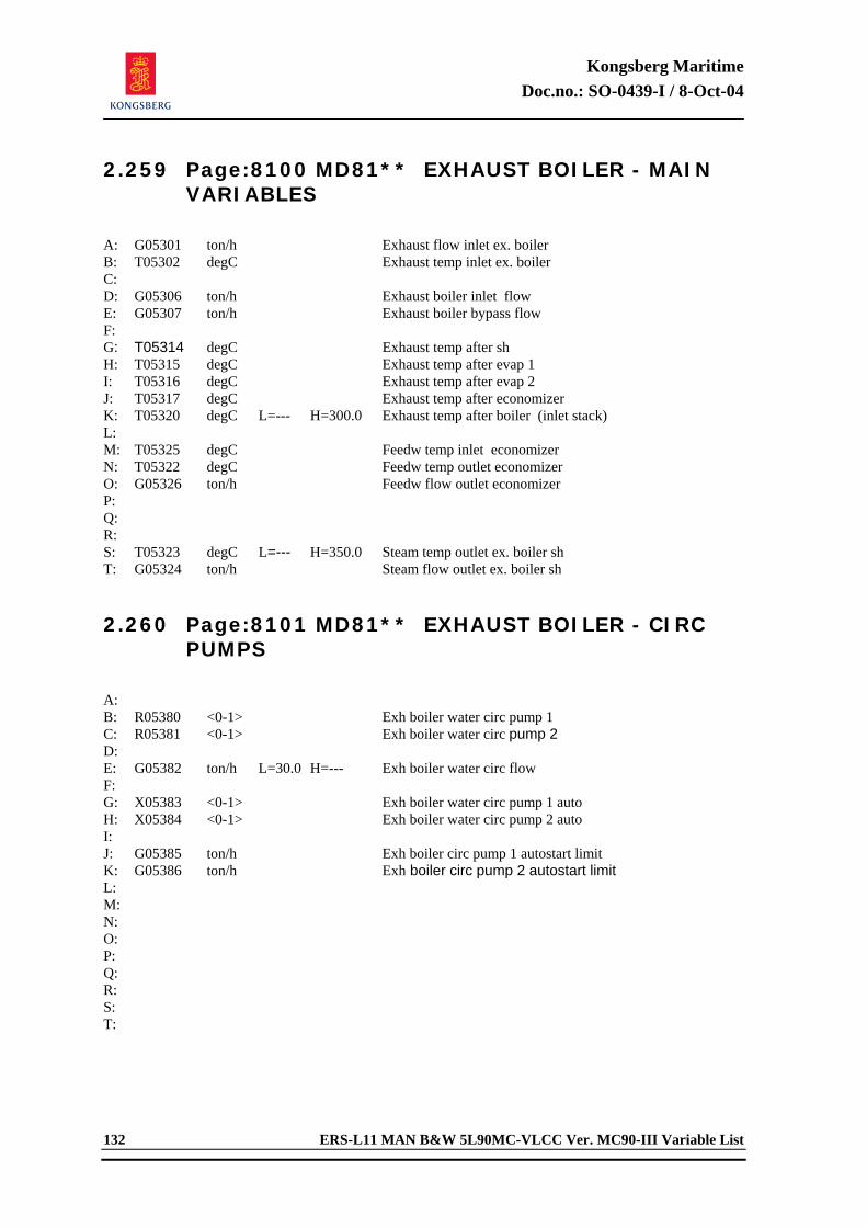
Kongsberg Maritime Doc.no.: SO-0439-I / 8-Oct-04
132 ERS-L11 MAN B&W 5L90MC-VLCC Ver. MC90-III Variable List
2.259 Page:8100 MD81** EXHAUST BOILER - MAIN VARIABLES
A: G05301 ton/h Exhaust flow inlet ex. boiler B: T05302 degC Exhaust temp inlet ex. boiler C: D: G05306 ton/h Exhaust boiler inlet flow E: G05307 ton/h Exhaust boiler bypass flow F: G: T05314 degC Exhaust temp after sh H: T05315 degC Exhaust temp after evap 1 I: T05316 degC Exhaust temp after evap 2 J: T05317 degC Exhaust temp after economizer K: T05320 degC L=--- H=300.0 Exhaust temp after boiler (inlet stack) L: M: T05325 degC Feedw temp inlet economizer N: T05322 degC Feedw temp outlet economizer O: G05326 ton/h Feedw flow outlet economizer P: Q: R: S: T05323 degC L=--- H=350.0 Steam temp outlet ex. boiler sh T: G05324 ton/h Steam flow outlet ex. boiler sh 2.260 Page:8101 MD81** EXHAUST BOILER - CIRC
PUMPS
A: B: R05380 <0-1> Exh boiler water circ pump 1 C: R05381 <0-1> Exh boiler water circ pump 2 D: E: G05382 ton/h L=30.0 H=--- Exh boiler water circ flow F: G: X05383 <0-1> Exh boiler water circ pump 1 auto H: X05384 <0-1> Exh boiler water circ pump 2 auto I: J: G05385 ton/h Exh boiler circ pump 1 autostart limit K: G05386 ton/h Exh boiler circ pump 2 autostart limit L: M: N: O: P: Q: R: S: T:
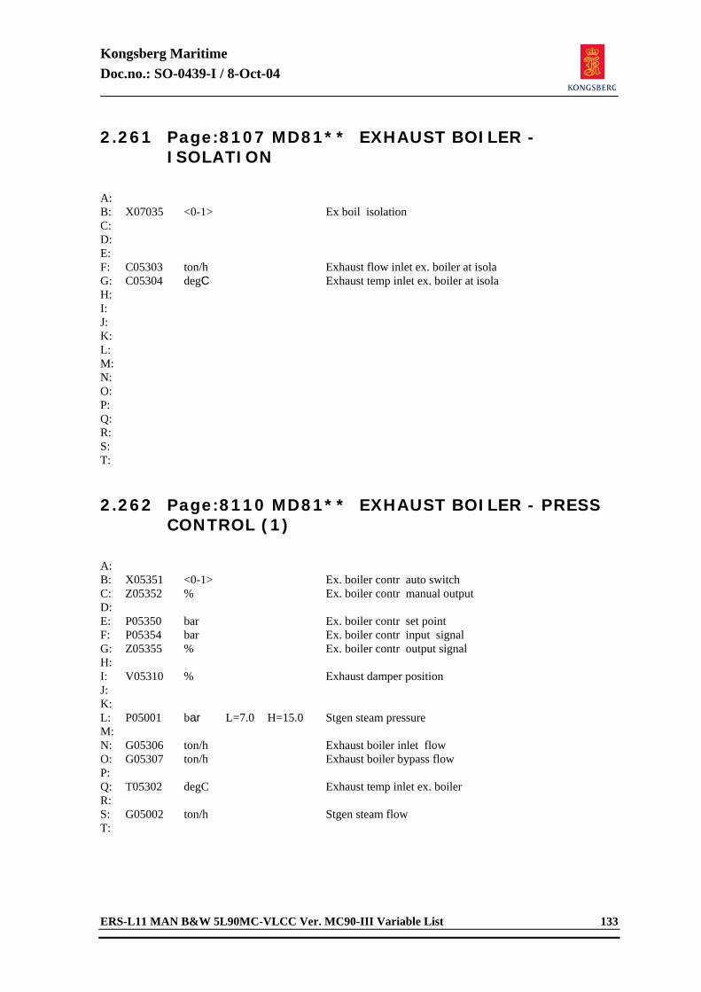
Kongsberg Maritime Doc.no.: SO-0439-I / 8-Oct-04
ERS-L11 MAN B&W 5L90MC-VLCC Ver. MC90-III Variable List 133
2.261 Page:8107 MD81** EXHAUST BOILER - ISOLATION
A: B: X07035 <0-1> Ex boil isolation C: D: E: F: C05303 ton/h Exhaust flow inlet ex. boiler at isola G: C05304 degC Exhaust temp inlet ex. boiler at isola H: I: J: K: L: M: N: O: P: Q: R: S: T: 2.262 Page:8110 MD81** EXHAUST BOILER - PRESS
CONTROL (1)
A: B: X05351 <0-1> Ex. boiler contr auto switch C: Z05352 % Ex. boiler contr manual output D: E: P05350 bar Ex. boiler contr set point F: P05354 bar Ex. boiler contr input signal G: Z05355 % Ex. boiler contr output signal H: I: V05310 % Exhaust damper position J: K: L: P05001 bar L=7.0 H=15.0 Stgen steam pressure M: N: G05306 ton/h Exhaust boiler inlet flow O: G05307 ton/h Exhaust boiler bypass flow P: Q: T05302 degC Exhaust temp inlet ex. boiler R: S: G05002 ton/h Stgen steam flow T:
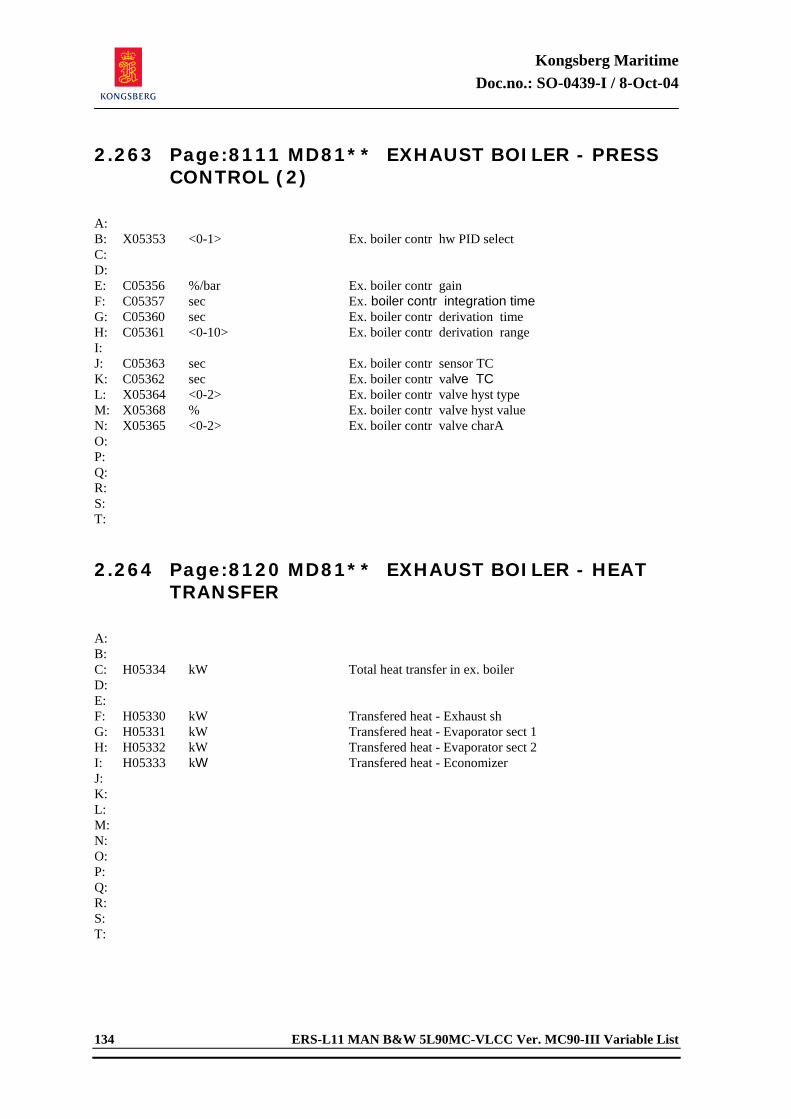
Kongsberg Maritime Doc.no.: SO-0439-I / 8-Oct-04
134 ERS-L11 MAN B&W 5L90MC-VLCC Ver. MC90-III Variable List
2.263 Page:8111 MD81** EXHAUST BOILER - PRESS CONTROL (2)
A: B: X05353 <0-1> Ex. boiler contr hw PID select C: D: E: C05356 %/bar Ex. boiler contr gain F: C05357 sec Ex. boiler contr integration time G: C05360 sec Ex. boiler contr derivation time H: C05361 <0-10> Ex. boiler contr derivation range I: J: C05363 sec Ex. boiler contr sensor TC K: C05362 sec Ex. boiler contr valve TC L: X05364 <0-2> Ex. boiler contr valve hyst type M: X05368 % Ex. boiler contr valve hyst value N: X05365 <0-2> Ex. boiler contr valve charA O: P: Q: R: S: T: 2.264 Page:8120 MD81** EXHAUST BOILER - HEAT
TRANSFER
A: B: C: H05334 kW Total heat transfer in ex. boiler D: E: F: H05330 kW Transfered heat - Exhaust sh G: H05331 kW Transfered heat - Evaporator sect 1 H: H05332 kW Transfered heat - Evaporator sect 2 I: H05333 kW Transfered heat - Economizer J: K: L: M: N: O: P: Q: R: S: T:
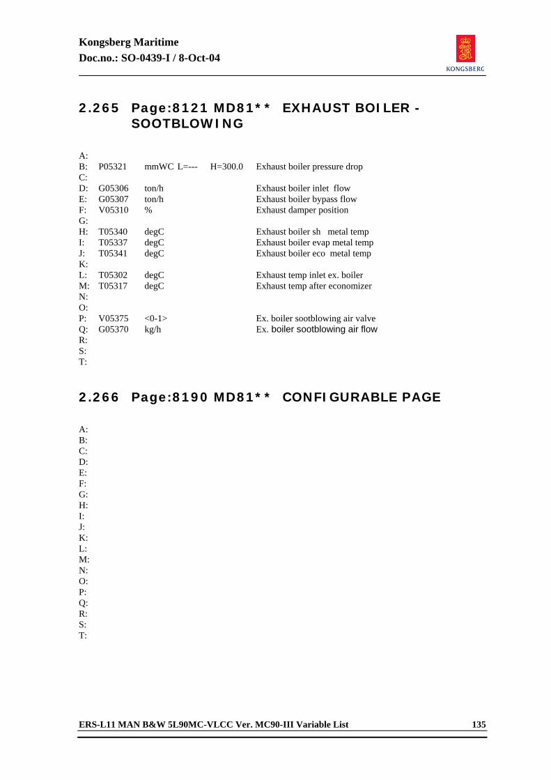
Kongsberg Maritime Doc.no.: SO-0439-I / 8-Oct-04
ERS-L11 MAN B&W 5L90MC-VLCC Ver. MC90-III Variable List 135
2.265 Page:8121 MD81** EXHAUST BOILER - SOOTBLOWING
A: B: P05321 mmWC L=--- H=300.0 Exhaust boiler pressure drop C: D: G05306 ton/h Exhaust boiler inlet flow E: G05307 ton/h Exhaust boiler bypass flow F: V05310 % Exhaust damper position G: H: T05340 degC Exhaust boiler sh metal temp I: T05337 degC Exhaust boiler evap metal temp J: T05341 degC Exhaust boiler eco metal temp K: L: T05302 degC Exhaust temp inlet ex. boiler M: T05317 degC Exhaust temp after economizer N: O: P: V05375 <0-1> Ex. boiler sootblowing air valve Q: G05370 kg/h Ex. boiler sootblowing air flow R: S: T: 2.266 Page:8190 MD81** CONFIGURABLE PAGE
A: B: C: D: E: F: G: H: I: J: K: L: M: N: O: P: Q: R: S: T:
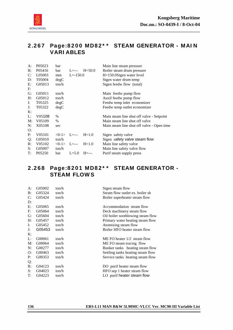
Kongsberg Maritime Doc.no.: SO-0439-I / 8-Oct-04
136 ERS-L11 MAN B&W 5L90MC-VLCC Ver. MC90-III Variable List
2.267 Page:8200 MD82** STEAM GENERATOR - MAIN VARIABLES
A: P05023 bar Main line steam pressure B: P05416 bar L=--- H=50.0 Boiler steam drum pressure C: L05003 mm L=-150.0 H=150.0 Stgen water level D: T05004 degC Stgen water drum temp E: G05013 ton/h Stgen feedw flow (total) F: G: G05011 ton/h Main feedw pump flow H: G05012 ton/h Auxil feedw pump flow I: T05325 degC Feedw temp inlet economizer J: T05322 degC Feedw temp outlet economizer K: L: V05108 % Main steam line shut off valve - Setpoint M: V05109 % Main steam line shut off valve N: X05108 sec Main steam line shut off valve - Open time O: P: V05101 <0-1> L=--- H=1.0 Stgen safety valve Q: G05010 ton/h Stgen safety valve steam flow R: V05102 <0-1> L=--- H=1.0 Main line safety valve S: G05007 ton/h Main line safety valve flow T: P05250 bar L=5.0 H=--- Purif steam supply press 2.268 Page:8201 MD82** STEAM GENERATOR -
STEAM FLOWS
A: G05002 ton/h Stgen steam flow B: G05324 ton/h Steam flow outlet ex. boiler sh C: G05424 ton/h Boiler superheater steam flow D: E: G05065 ton/h Accommodation steam flow F: G05064 ton/h Deck machinery steam flow G: G05604 ton/h Oil boiler sootblowing steam flow H: G05457 ton/h Primary water heating steam flow I: G05452 ton/h Atomizing steam flow J: G05453 ton/h Boiler HFO heater steam flow K: L: G00061 ton/h ME FO heater 1/2 steam flow M: G00064 ton/h ME FO steam tracing flow N: G00277 ton/h Bunker tanks heating steam flow O: G00463 ton/h Settling tanks heating steam flow P: G00353 ton/h Service tanks heating steam flow Q: R: G04123 ton/h DO purif heater steam flow S: G04023 ton/h HFO sep 1 heater steam flow T: G04223 ton/h LO purif heater steam flow
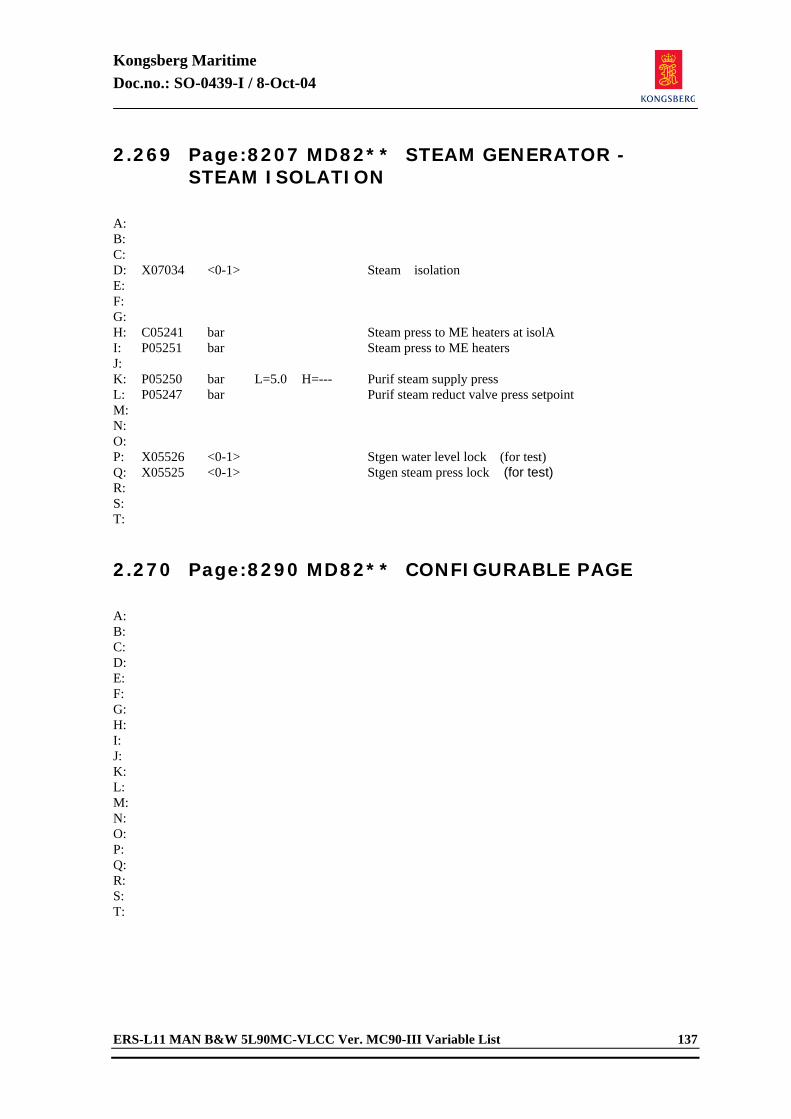
Kongsberg Maritime Doc.no.: SO-0439-I / 8-Oct-04
ERS-L11 MAN B&W 5L90MC-VLCC Ver. MC90-III Variable List 137
2.269 Page:8207 MD82** STEAM GENERATOR - STEAM ISOLATION
A: B: C: D: X07034 <0-1> Steam isolation E: F: G: H: C05241 bar Steam press to ME heaters at isolA I: P05251 bar Steam press to ME heaters J: K: P05250 bar L=5.0 H=--- Purif steam supply press L: P05247 bar Purif steam reduct valve press setpoint M: N: O: P: X05526 <0-1> Stgen water level lock (for test) Q: X05525 <0-1> Stgen steam press lock (for test) R: S: T: 2.270 Page:8290 MD82** CONFIGURABLE PAGE
A: B: C: D: E: F: G: H: I: J: K: L: M: N: O: P: Q: R: S: T:
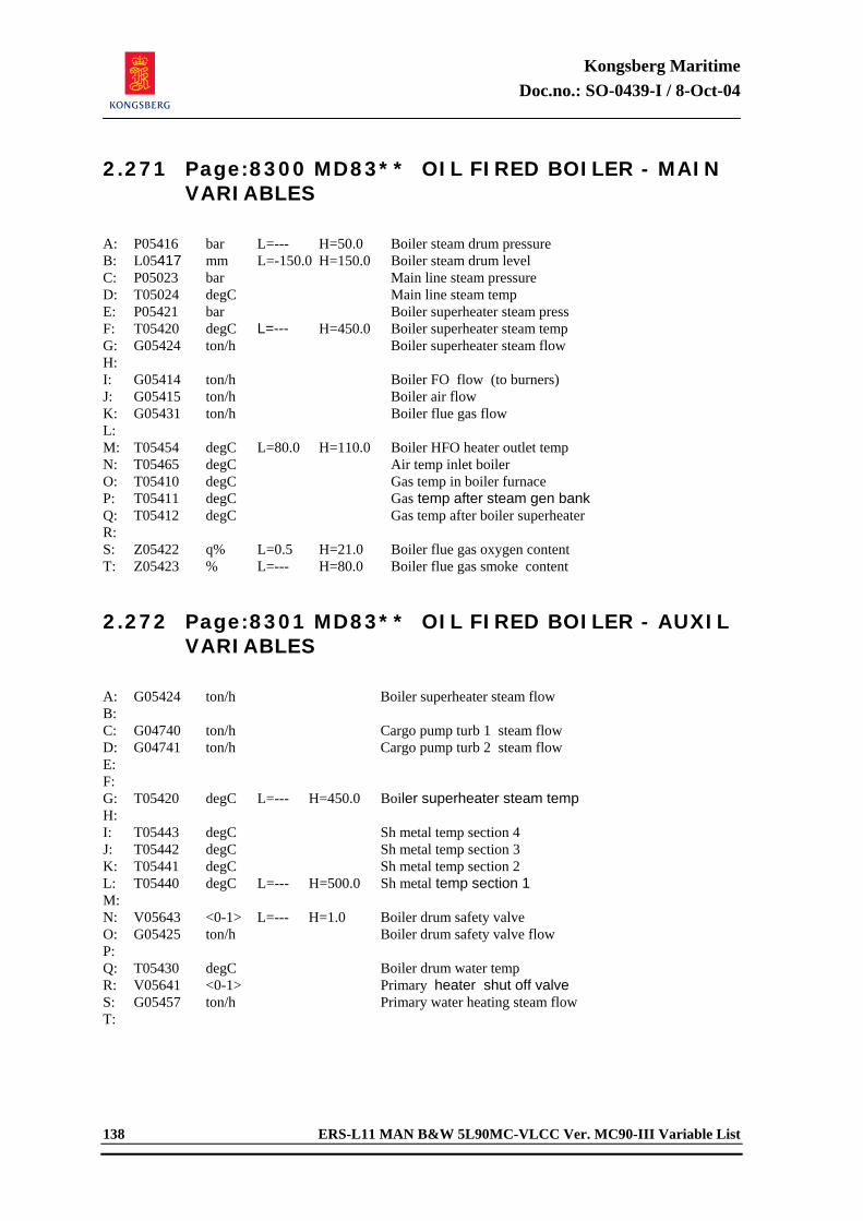
Kongsberg Maritime Doc.no.: SO-0439-I / 8-Oct-04
138 ERS-L11 MAN B&W 5L90MC-VLCC Ver. MC90-III Variable List
2.271 Page:8300 MD83** OIL FIRED BOILER - MAIN VARIABLES
A: P05416 bar L=--- H=50.0 Boiler steam drum pressure B: L05417 mm L=-150.0 H=150.0 Boiler steam drum level C: P05023 bar Main line steam pressure D: T05024 degC Main line steam temp E: P05421 bar Boiler superheater steam press F: T05420 degC L=--- H=450.0 Boiler superheater steam temp G: G05424 ton/h Boiler superheater steam flow H: I: G05414 ton/h Boiler FO flow (to burners) J: G05415 ton/h Boiler air flow K: G05431 ton/h Boiler flue gas flow L: M: T05454 degC L=80.0 H=110.0 Boiler HFO heater outlet temp N: T05465 degC Air temp inlet boiler O: T05410 degC Gas temp in boiler furnace P: T05411 degC Gas temp after steam gen bank Q: T05412 degC Gas temp after boiler superheater R: S: Z05422 q% L=0.5 H=21.0 Boiler flue gas oxygen content T: Z05423 % L=--- H=80.0 Boiler flue gas smoke content 2.272 Page:8301 MD83** OIL FIRED BOILER - AUXIL
VARIABLES
A: G05424 ton/h Boiler superheater steam flow B: C: G04740 ton/h Cargo pump turb 1 steam flow D: G04741 ton/h Cargo pump turb 2 steam flow E: F: G: T05420 degC L=--- H=450.0 Boiler superheater steam temp H: I: T05443 degC Sh metal temp section 4 J: T05442 degC Sh metal temp section 3 K: T05441 degC Sh metal temp section 2 L: T05440 degC L=--- H=500.0 Sh metal temp section 1 M: N: V05643 <0-1> L=--- H=1.0 Boiler drum safety valve O: G05425 ton/h Boiler drum safety valve flow P: Q: T05430 degC Boiler drum water temp R: V05641 <0-1> Primary heater shut off valve S: G05457 ton/h Primary water heating steam flow T:
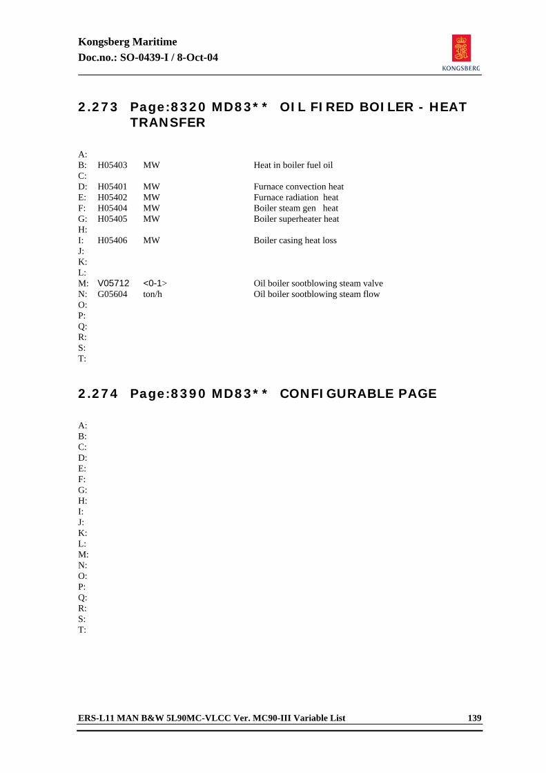
Kongsberg Maritime Doc.no.: SO-0439-I / 8-Oct-04
ERS-L11 MAN B&W 5L90MC-VLCC Ver. MC90-III Variable List 139
2.273 Page:8320 MD83** OIL FIRED BOILER - HEAT TRANSFER
A: B: H05403 MW Heat in boiler fuel oil C: D: H05401 MW Furnace convection heat E: H05402 MW Furnace radiation heat F: H05404 MW Boiler steam gen heat G: H05405 MW Boiler superheater heat H: I: H05406 MW Boiler casing heat loss J: K: L: M: V05712 <0-1> Oil boiler sootblowing steam valve N: G05604 ton/h Oil boiler sootblowing steam flow O: P: Q: R: S: T: 2.274 Page:8390 MD83** CONFIGURABLE PAGE
A: B: C: D: E: F: G: H: I: J: K: L: M: N: O: P: Q: R: S: T:
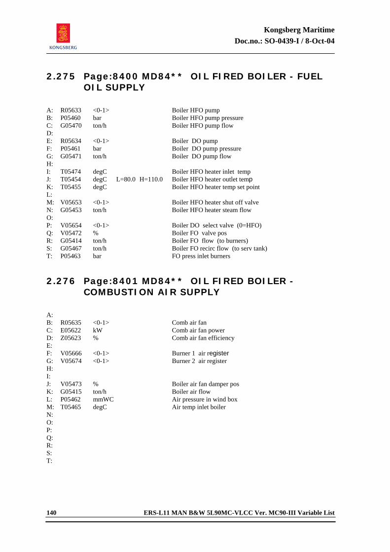
Kongsberg Maritime Doc.no.: SO-0439-I / 8-Oct-04
140 ERS-L11 MAN B&W 5L90MC-VLCC Ver. MC90-III Variable List
2.275 Page:8400 MD84** OIL FIRED BOILER - FUEL OIL SUPPLY
A: R05633 <0-1> Boiler HFO pump B: P05460 bar Boiler HFO pump pressure C: G05470 ton/h Boiler HFO pump flow D: E: R05634 <0-1> Boiler DO pump F: P05461 bar Boiler DO pump pressure G: G05471 ton/h Boiler DO pump flow H: I: T05474 degC Boiler HFO heater inlet temp J: T05454 degC L=80.0 H=110.0 Boiler HFO heater outlet temp K: T05455 degC Boiler HFO heater temp set point L: M: V05653 <0-1> Boiler HFO heater shut off valve N: G05453 ton/h Boiler HFO heater steam flow O: P: V05654 <0-1> Boiler DO select valve (0=HFO) Q: V05472 % Boiler FO valve pos R: G05414 ton/h Boiler FO flow (to burners) S: G05467 ton/h Boiler FO recirc flow (to serv tank) T: P05463 bar FO press inlet burners 2.276 Page:8401 MD84** OIL FIRED BOILER -
COMBUSTION AIR SUPPLY
A: B: R05635 <0-1> Comb air fan C: E05622 kW Comb air fan power D: Z05623 % Comb air fan efficiency E: F: V05666 <0-1> Burner 1 air register G: V05674 <0-1> Burner 2 air register H: I: J: V05473 % Boiler air fan damper pos K: G05415 ton/h Boiler air flow L: P05462 mmWC Air pressure in wind box M: T05465 degC Air temp inlet boiler N: O: P: Q: R: S: T:
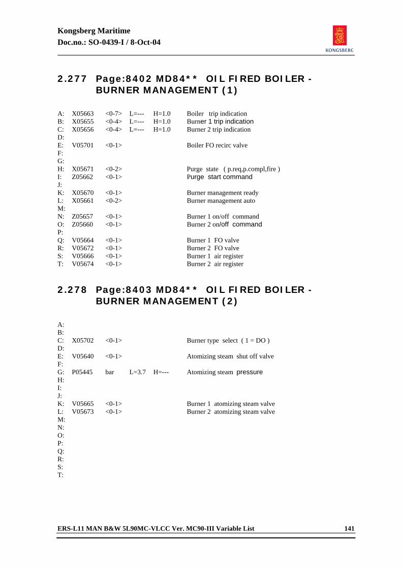
Kongsberg Maritime Doc.no.: SO-0439-I / 8-Oct-04
ERS-L11 MAN B&W 5L90MC-VLCC Ver. MC90-III Variable List 141
2.277 Page:8402 MD84** OIL FIRED BOILER - BURNER MANAGEMENT (1)
A: X05663 <0-7> L=--- H=1.0 Boiler trip indication B: X05655 <0-4> L=--- H=1.0 Burner 1 trip indication C: X05656 <0-4> L=--- H=1.0 Burner 2 trip indication D: E: V05701 <0-1> Boiler FO recirc valve F: G: H: X05671 <0-2> Purge state ( p.req,p.compl,fire ) I: Z05662 <0-1> Purge start command J: K: X05670 <0-1> Burner management ready L: X05661 <0-2> Burner management auto M: N: Z05657 <0-1> Burner 1 on/off command O: Z05660 <0-1> Burner 2 on/off command P: Q: V05664 <0-1> Burner 1 FO valve R: V05672 <0-1> Burner 2 FO valve S: V05666 <0-1> Burner 1 air register T: V05674 <0-1> Burner 2 air register 2.278 Page:8403 MD84** OIL FIRED BOILER -
BURNER MANAGEMENT (2)
A: B: C: X05702 <0-1> Burner type select ( 1 = DO ) D: E: V05640 <0-1> Atomizing steam shut off valve F: G: P05445 bar L=3.7 H=--- Atomizing steam pressure H: I: J: K: V05665 <0-1> Burner 1 atomizing steam valve L: V05673 <0-1> Burner 2 atomizing steam valve M: N: O: P: Q: R: S: T:
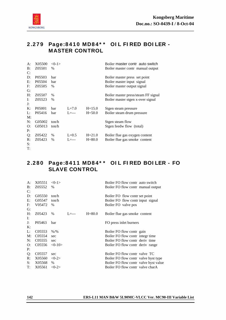
Kongsberg Maritime Doc.no.: SO-0439-I / 8-Oct-04
142 ERS-L11 MAN B&W 5L90MC-VLCC Ver. MC90-III Variable List
2.279 Page:8410 MD84** OIL FIRED BOILER - MASTER CONTROL
A: X05500 <0-1> Boiler master contr auto switch B: Z05501 % Boiler master contr manual output C: D: P05503 bar Boiler master press set point E: P05504 bar Boiler master input signal F: Z05505 % Boiler master output signal G: H: Z05507 % Boiler master press/steam FF signal I: Z05523 % Boiler master stgen x-over signal J: K: P05001 bar L=7.0 H=15.0 Stgen steam pressure L: P05416 bar L=--- H=50.0 Boiler steam drum pressure M: N: G05002 ton/h Stgen steam flow O: G05013 ton/h Stgen feedw flow (total) P: Q: Z05422 % L=0.5 H=21.0 Boiler flue gas oxygen content R: Z05423 % L=--- H=80.0 Boiler flue gas smoke content S: T: 2.280 Page:8411 MD84** OIL FIRED BOILER - FO
SLAVE CONTROL
A: X05551 <0-1> Boiler FO flow contr auto switch B: Z05552 % Boiler FO flow contr manual output C: D: G05550 ton/h Boiler FO flow contr set point E: G05547 ton/h Boiler FO flow contr input signal F: V05472 % Boiler FO valve pos G: H: Z05423 % L=--- H=80.0 Boiler flue gas smoke content I: J: P05463 bar FO press inlet burners K: L: C05553 %/% Boiler FO flow contr gain M: C05554 sec Boiler FO flow contr integr time N: C05555 sec Boiler FO flow contr deriv time O: C05556 <0-10> Boiler FO flow contr deriv range P: Q: C05557 sec Boiler FO flow contr valve TC R: X05560 <0-2> Boiler FO flow contr valve hyst type S: X05568 % Boiler FO flow contr valve hyst value T: X05561 <0-2> Boiler FO flow contr valve charA
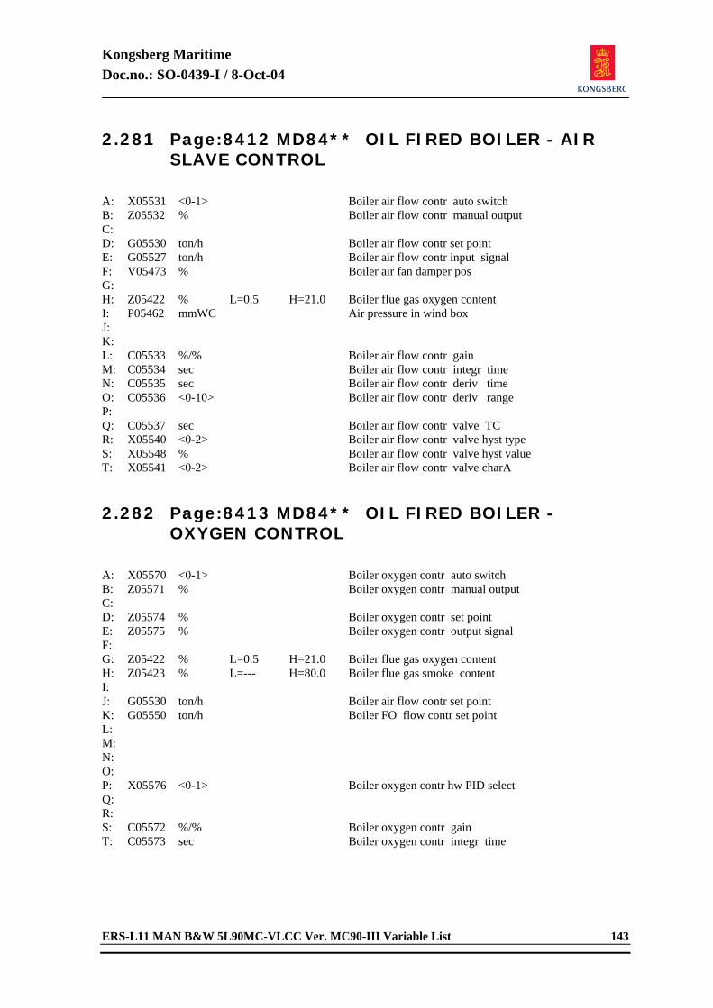
Kongsberg Maritime Doc.no.: SO-0439-I / 8-Oct-04
ERS-L11 MAN B&W 5L90MC-VLCC Ver. MC90-III Variable List 143
2.281 Page:8412 MD84** OIL FIRED BOILER - AIR SLAVE CONTROL
A: X05531 <0-1> Boiler air flow contr auto switch B: Z05532 % Boiler air flow contr manual output C: D: G05530 ton/h Boiler air flow contr set point E: G05527 ton/h Boiler air flow contr input signal F: V05473 % Boiler air fan damper pos G: H: Z05422 % L=0.5 H=21.0 Boiler flue gas oxygen content I: P05462 mmWC Air pressure in wind box J: K: L: C05533 %/% Boiler air flow contr gain M: C05534 sec Boiler air flow contr integr time N: C05535 sec Boiler air flow contr deriv time O: C05536 <0-10> Boiler air flow contr deriv range P: Q: C05537 sec Boiler air flow contr valve TC R: X05540 <0-2> Boiler air flow contr valve hyst type S: X05548 % Boiler air flow contr valve hyst value T: X05541 <0-2> Boiler air flow contr valve charA 2.282 Page:8413 MD84** OIL FIRED BOILER -
OXYGEN CONTROL
A: X05570 <0-1> Boiler oxygen contr auto switch B: Z05571 % Boiler oxygen contr manual output C: D: Z05574 % Boiler oxygen contr set point E: Z05575 % Boiler oxygen contr output signal F: G: Z05422 % L=0.5 H=21.0 Boiler flue gas oxygen content H: Z05423 % L=--- H=80.0 Boiler flue gas smoke content I: J: G05530 ton/h Boiler air flow contr set point K: G05550 ton/h Boiler FO flow contr set point L: M: N: O: P: X05576 <0-1> Boiler oxygen contr hw PID select Q: R: S: C05572 %/% Boiler oxygen contr gain T: C05573 sec Boiler oxygen contr integr time
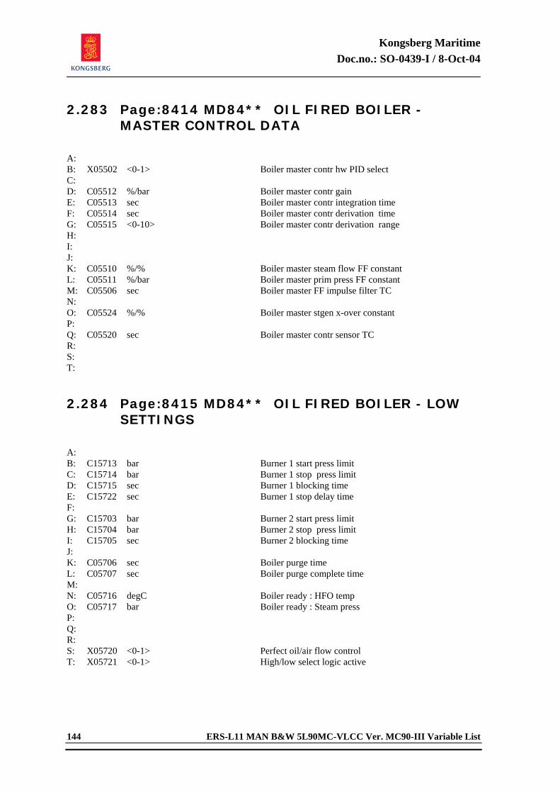
Kongsberg Maritime Doc.no.: SO-0439-I / 8-Oct-04
144 ERS-L11 MAN B&W 5L90MC-VLCC Ver. MC90-III Variable List
2.283 Page:8414 MD84** OIL FIRED BOILER - MASTER CONTROL DATA
A: B: X05502 <0-1> Boiler master contr hw PID select C: D: C05512 %/bar Boiler master contr gain E: C05513 sec Boiler master contr integration time F: C05514 sec Boiler master contr derivation time G: C05515 <0-10> Boiler master contr derivation range H: I: J: K: C05510 %/% Boiler master steam flow FF constant L: C05511 %/bar Boiler master prim press FF constant M: C05506 sec Boiler master FF impulse filter TC N: O: C05524 %/% Boiler master stgen x-over constant P: Q: C05520 sec Boiler master contr sensor TC R: S: T: 2.284 Page:8415 MD84** OIL FIRED BOILER - LOW
SETTINGS
A: B: C15713 bar Burner 1 start press limit C: C15714 bar Burner 1 stop press limit D: C15715 sec Burner 1 blocking time E: C15722 sec Burner 1 stop delay time F: G: C15703 bar Burner 2 start press limit H: C15704 bar Burner 2 stop press limit I: C15705 sec Burner 2 blocking time J: K: C05706 sec Boiler purge time L: C05707 sec Boiler purge complete time M: N: C05716 degC Boiler ready : HFO temp O: C05717 bar Boiler ready : Steam press P: Q: R: S: X05720 <0-1> Perfect oil/air flow control T: X05721 <0-1> High/low select logic active
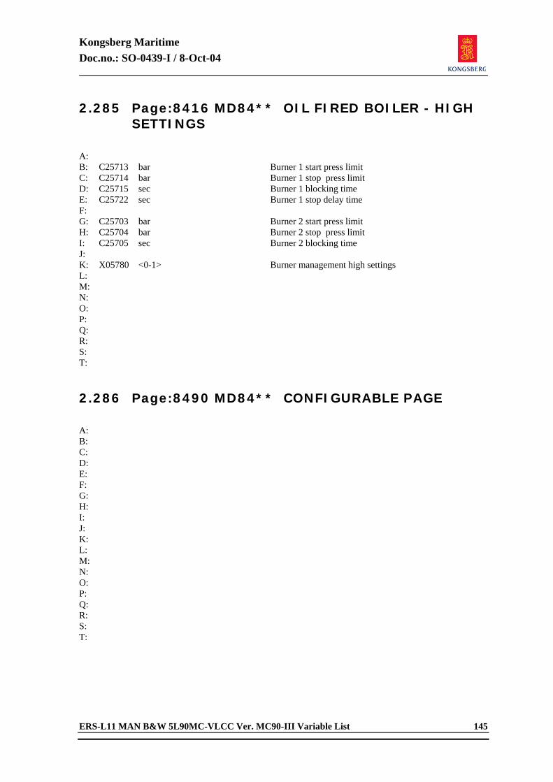
Kongsberg Maritime Doc.no.: SO-0439-I / 8-Oct-04
ERS-L11 MAN B&W 5L90MC-VLCC Ver. MC90-III Variable List 145
2.285 Page:8416 MD84** OIL FIRED BOILER - HIGH SETTINGS
A: B: C25713 bar Burner 1 start press limit C: C25714 bar Burner 1 stop press limit D: C25715 sec Burner 1 blocking time E: C25722 sec Burner 1 stop delay time F: G: C25703 bar Burner 2 start press limit H: C25704 bar Burner 2 stop press limit I: C25705 sec Burner 2 blocking time J: K: X05780 <0-1> Burner management high settings L: M: N: O: P: Q: R: S: T: 2.286 Page:8490 MD84** CONFIGURABLE PAGE
A: B: C: D: E: F: G: H: I: J: K: L: M: N: O: P: Q: R: S: T:
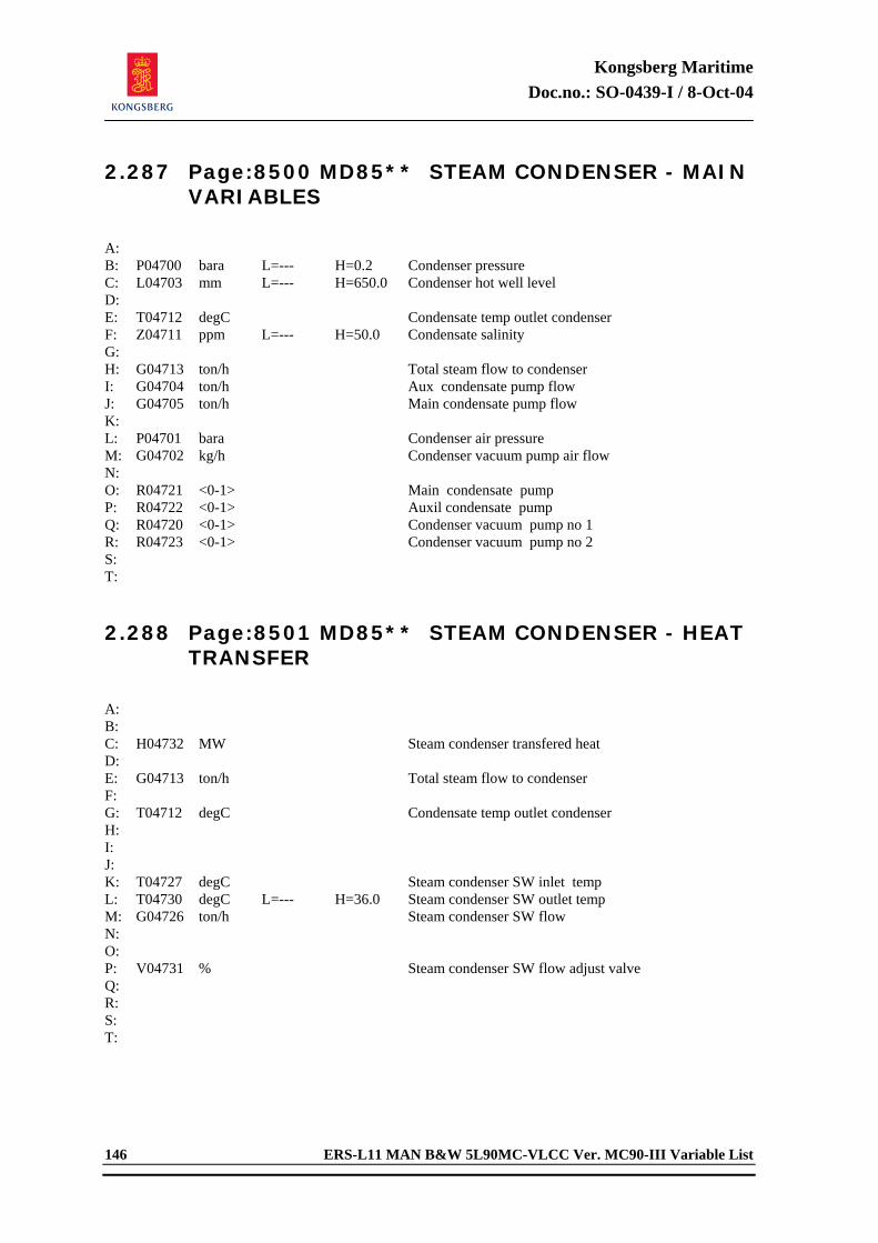
Kongsberg Maritime Doc.no.: SO-0439-I / 8-Oct-04
146 ERS-L11 MAN B&W 5L90MC-VLCC Ver. MC90-III Variable List
2.287 Page:8500 MD85** STEAM CONDENSER - MAIN VARIABLES
A: B: P04700 bara L=--- H=0.2 Condenser pressure C: L04703 mm L=--- H=650.0 Condenser hot well level D: E: T04712 degC Condensate temp outlet condenser F: Z04711 ppm L=--- H=50.0 Condensate salinity G: H: G04713 ton/h Total steam flow to condenser I: G04704 ton/h Aux condensate pump flow J: G04705 ton/h Main condensate pump flow K: L: P04701 bara Condenser air pressure M: G04702 kg/h Condenser vacuum pump air flow N: O: R04721 <0-1> Main condensate pump P: R04722 <0-1> Auxil condensate pump Q: R04720 <0-1> Condenser vacuum pump no 1 R: R04723 <0-1> Condenser vacuum pump no 2 S: T: 2.288 Page:8501 MD85** STEAM CONDENSER - HEAT
TRANSFER
A: B: C: H04732 MW Steam condenser transfered heat D: E: G04713 ton/h Total steam flow to condenser F: G: T04712 degC Condensate temp outlet condenser H: I: J: K: T04727 degC Steam condenser SW inlet temp L: T04730 degC L=--- H=36.0 Steam condenser SW outlet temp M: G04726 ton/h Steam condenser SW flow N: O: P: V04731 % Steam condenser SW flow adjust valve Q: R: S: T:
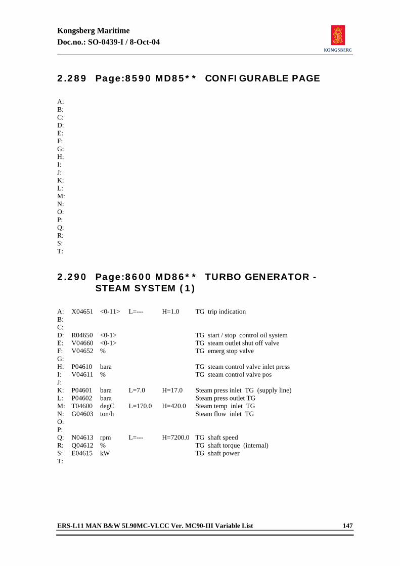
Kongsberg Maritime Doc.no.: SO-0439-I / 8-Oct-04
ERS-L11 MAN B&W 5L90MC-VLCC Ver. MC90-III Variable List 147
2.289 Page:8590 MD85** CONFIGURABLE PAGE
A: B: C: D: E: F: G: H: I: J: K: L: M: N: O: P: Q: R: S: T: 2.290 Page:8600 MD86** TURBO GENERATOR -
STEAM SYSTEM (1)
A: X04651 <0-11> L=--- H=1.0 TG trip indication B: C: D: R04650 <0-1> TG start / stop control oil system E: V04660 <0-1> TG steam outlet shut off valve F: V04652 % TG emerg stop valve G: H: P04610 bara TG steam control valve inlet press I: V04611 % TG steam control valve pos J: K: P04601 bara L=7.0 H=17.0 Steam press inlet TG (supply line) L: P04602 bara Steam press outlet TG M: T04600 degC L=170.0 H=420.0 Steam temp inlet TG N: G04603 ton/h Steam flow inlet TG O: P: Q: N04613 rpm L=--- H=7200.0 TG shaft speed R: Q04612 % TG shaft torque (internal) S: E04615 kW TG shaft power T:
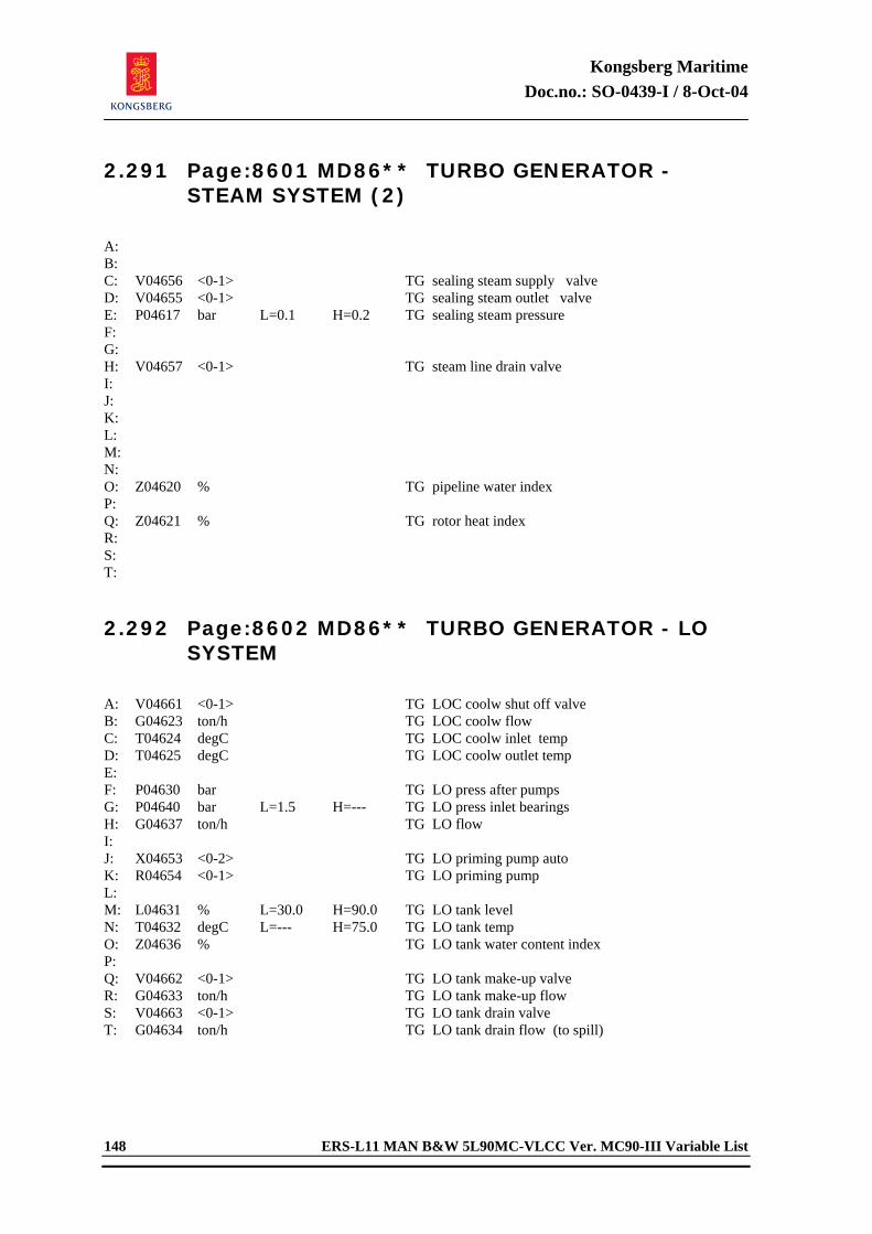
Kongsberg Maritime Doc.no.: SO-0439-I / 8-Oct-04
148 ERS-L11 MAN B&W 5L90MC-VLCC Ver. MC90-III Variable List
2.291 Page:8601 MD86** TURBO GENERATOR - STEAM SYSTEM (2)
A: B: C: V04656 <0-1> TG sealing steam supply valve D: V04655 <0-1> TG sealing steam outlet valve E: P04617 bar L=0.1 H=0.2 TG sealing steam pressure F: G: H: V04657 <0-1> TG steam line drain valve I: J: K: L: M: N: O: Z04620 % TG pipeline water index P: Q: Z04621 % TG rotor heat index R: S: T: 2.292 Page:8602 MD86** TURBO GENERATOR - LO
SYSTEM
A: V04661 <0-1> TG LOC coolw shut off valve B: G04623 ton/h TG LOC coolw flow C: T04624 degC TG LOC coolw inlet temp D: T04625 degC TG LOC coolw outlet temp E: F: P04630 bar TG LO press after pumps G: P04640 bar L=1.5 H=--- TG LO press inlet bearings H: G04637 ton/h TG LO flow I: J: X04653 <0-2> TG LO priming pump auto K: R04654 <0-1> TG LO priming pump L: M: L04631 % L=30.0 H=90.0 TG LO tank level N: T04632 degC L=--- H=75.0 TG LO tank temp O: Z04636 % TG LO tank water content index P: Q: V04662 <0-1> TG LO tank make-up valve R: G04633 ton/h TG LO tank make-up flow S: V04663 <0-1> TG LO tank drain valve T: G04634 ton/h TG LO tank drain flow (to spill)
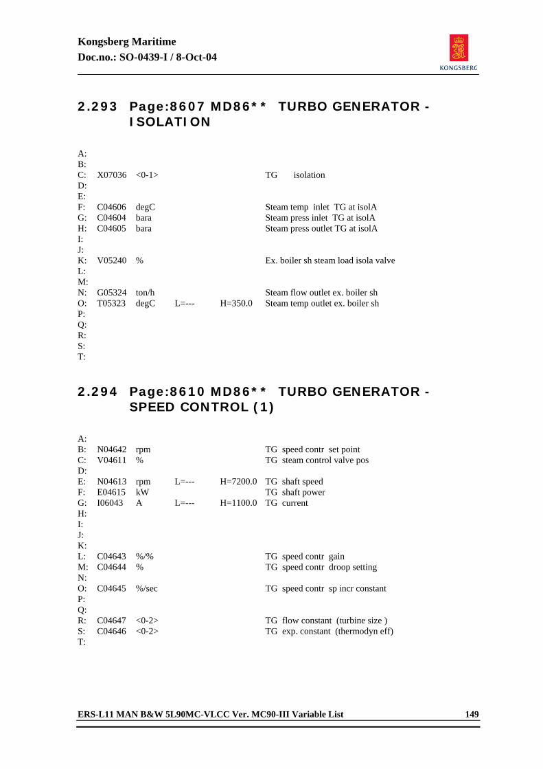
Kongsberg Maritime Doc.no.: SO-0439-I / 8-Oct-04
ERS-L11 MAN B&W 5L90MC-VLCC Ver. MC90-III Variable List 149
2.293 Page:8607 MD86** TURBO GENERATOR - ISOLATION
A: B: C: X07036 <0-1> TG isolation D: E: F: C04606 degC Steam temp inlet TG at isolA G: C04604 bara Steam press inlet TG at isolA H: C04605 bara Steam press outlet TG at isolA I: J: K: V05240 % Ex. boiler sh steam load isola valve L: M: N: G05324 ton/h Steam flow outlet ex. boiler sh O: T05323 degC L=--- H=350.0 Steam temp outlet ex. boiler sh P: Q: R: S: T: 2.294 Page:8610 MD86** TURBO GENERATOR -
SPEED CONTROL (1)
A: B: N04642 rpm TG speed contr set point C: V04611 % TG steam control valve pos D: E: N04613 rpm L=--- H=7200.0 TG shaft speed F: E04615 kW TG shaft power G: I06043 A L=--- H=1100.0 TG current H: I: J: K: L: C04643 %/% TG speed contr gain M: C04644 % TG speed contr droop setting N: O: C04645 %/sec TG speed contr sp incr constant P: Q: R: C04647 <0-2> TG flow constant (turbine size ) S: C04646 <0-2> TG exp. constant (thermodyn eff) T:
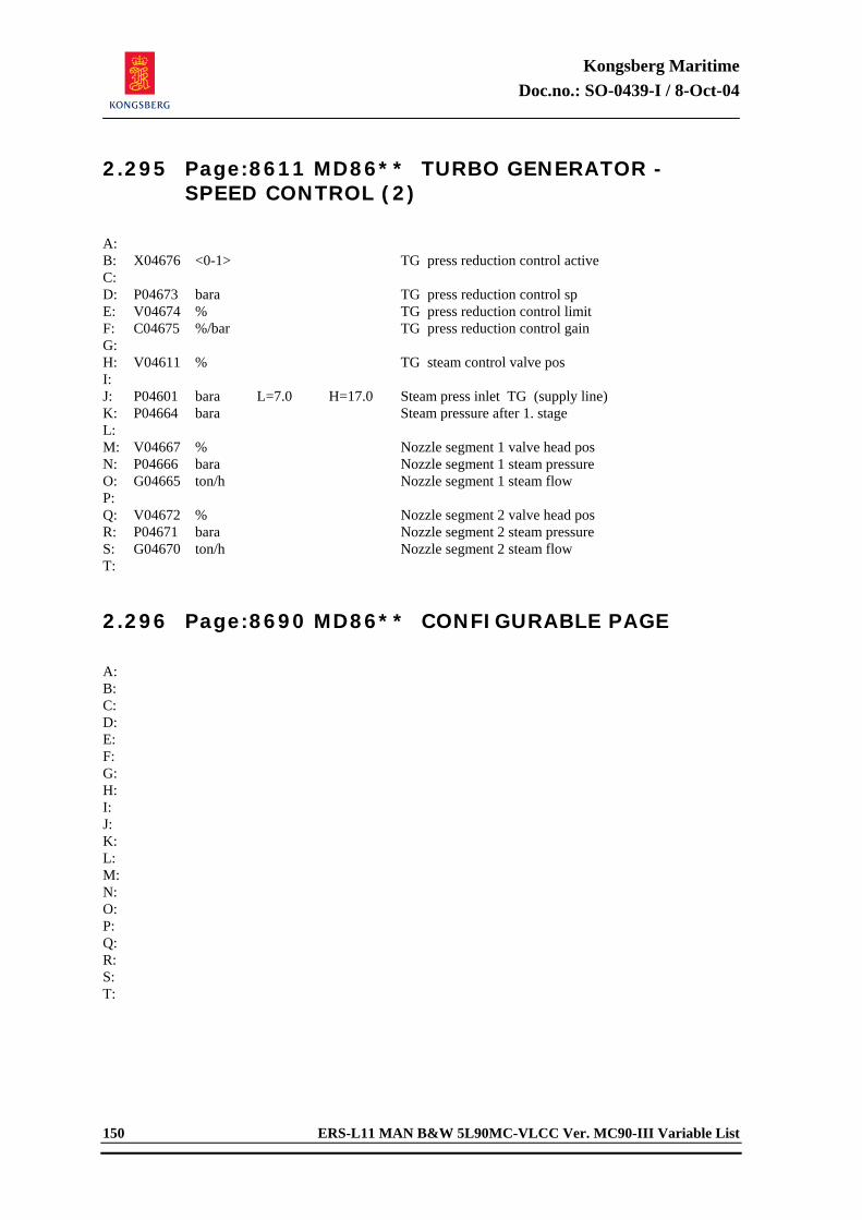
Kongsberg Maritime Doc.no.: SO-0439-I / 8-Oct-04
150 ERS-L11 MAN B&W 5L90MC-VLCC Ver. MC90-III Variable List
2.295 Page:8611 MD86** TURBO GENERATOR - SPEED CONTROL (2)
A: B: X04676 <0-1> TG press reduction control active C: D: P04673 bara TG press reduction control sp E: V04674 % TG press reduction control limit F: C04675 %/bar TG press reduction control gain G: H: V04611 % TG steam control valve pos I: J: P04601 bara L=7.0 H=17.0 Steam press inlet TG (supply line) K: P04664 bara Steam pressure after 1. stage L: M: V04667 % Nozzle segment 1 valve head pos N: P04666 bara Nozzle segment 1 steam pressure O: G04665 ton/h Nozzle segment 1 steam flow P: Q: V04672 % Nozzle segment 2 valve head pos R: P04671 bara Nozzle segment 2 steam pressure S: G04670 ton/h Nozzle segment 2 steam flow T: 2.296 Page:8690 MD86** CONFIGURABLE PAGE
A: B: C: D: E: F: G: H: I: J: K: L: M: N: O: P: Q: R: S: T:
Kongsberg Maritime Doc.no.: SO-0439-I / 8-Oct-04
ERS-L11 MAN B&W 5L90MC-VLCC Ver. MC90-III Variable List 151
2.297 Page:8700 MD87** CARGO PUMP TURBINE 1 (1 of 3)
A: B: V05800 % Cargo pump turbine 1 inlet stop valve C: E05801 kW Cargo pump turbine 1 power D: N05802 rpm Cargo pump turbine 1 speed E: F: N05804 rpm Cargo pump turbine 1 speed set point G: V05808 % Cargo pump turbine 1 control valve pos H: I: G05810 ton/h Cargo pump turbine 1 steam supply flow J: G05811 ton/h Cargo pump turbine 1 steam outlet flow K: T05812 degC Cargo pump turbine 1 steam outlet temp L: H05813 kcal/kg Cargo pump turbine 1 steam outlet enth M: X05814 <0-1> Cargo pump turbine 1 steam outlet qual N: O: G05816 ton/h Cargo pump turbine 1 steam to gland cond P: G05817 ton/h Cargo pump turbine 1 steam loss (to atm.) Q: R: P05810 bar Cargo pump turbine 1 steam inlet press S: T: 2.298 Page:8701 MD87** CARGO PUMP TURBINE 1
(2 of 3)
A: B: V05820 <0-1> Cargo pump turbine 1 exhaust shut off v C: V05821 <0-1> Cargo pump turbine 1 supply line drain v D: V05822 <0-1> Cargo pump turbine 1 casing drain valve E: V05823 <0-1> Cargo pump turbine 1 gland steam valve F: G: G05818 ton/h Cargo pump turbine 1 casing drain H: G05819 ton/h Cargo pump turbine 1 steam line drain I: J: Z05825 % Cargo pump turbine 1 line water index K: L: M: X05833 <0-5> L=--- H=1.0 Cargo pump turbine 1 trip N: R05834 <0-1> Cargo pump turbine 1 run O: P: Q: R: S: T:
Kongsberg Maritime Doc.no.: SO-0439-I / 8-Oct-04
152 ERS-L11 MAN B&W 5L90MC-VLCC Ver. MC90-III Variable List
2.299 Page:8702 MD87** CARGO PUMP TURBINE 1 (3 of 3)
A: B: V05828 <0-1> Cargo pump turbine 1 LO filter 1 C: V05829 <0-1> Cargo pump turbine 1 LO filter 2 D: V05830 <0-1> Cargo pump turbine 1 LO cooler SW valve E: F: R05835 <0-1> Cargo pump turb 1 electric starting pump G: P05836 bar Cargo pump turb 1 LO pump discharge press H: P05837 bar Cargo pump turb 1 LO filter diff pressure I: P05838 bar L=1.5 H=--- Cargo pump turb 1 LO press inlet bearings J: V05839 - Cargo pump turb 1 LO recirc valve pos K: L05840 % L=40.0 H=90.0 Cargo pump turb 1 LO sump tank level L: T05841 degC L=--- H=60.0 Cargo pump turb 1 LO sump tank temp M: N: O: P05844 bar Cargo pump 1 counter pressure P: V05845 % Cargo pump 1 discharge valve Q: G05846 ton/h Cargo pump 1 flow R: E05847 kW Cargo pump 1 power S: N05848 rpm Cargo pump 1 speed T: 2.300 Page:8703 MD87** CARGO PUMP TURBINE 2
(1 of 3)
A: B: V05850 % Cargo pump turbine 2 inlet stop valve C: E05851 kW Cargo pump turbine 2 power D: N05852 rpm Cargo pump turbine 2 speed E: F: N05854 rpm Cargo pump turbine 2 speed set point G: V05858 % Cargo pump turbine 2 control valve pos H: I: G05860 ton/h Cargo pump turbine 2 steam supply flow J: G05861 ton/h Cargo pump turbine 2 steam outlet flow K: T05862 degC Cargo pump turbine 2 steam outlet temp L: H05863 kcal/kg Cargo pump turbine 2 steam outlet enth M: X05864 <0-1> Cargo pump turbine 2 steam outlet qual N: O: G05866 ton/h Cargo pump turbine 2 steam to gland cond P: G05867 ton/h Cargo pump turbine 2 steam loss (to atm.) Q: R: P05860 bar Cargo pump turbine 2 steam inlet press S: T:
Kongsberg Maritime Doc.no.: SO-0439-I / 8-Oct-04
ERS-L11 MAN B&W 5L90MC-VLCC Ver. MC90-III Variable List 153
2.301 Page:8704 MD87** CARGO PUMP TURBINE 2 (2 of 3)
A: B: V05870 <0-1> Cargo pump turbine 2 exhaust shut off v C: V05871 <0-1> Cargo pump turbine 2 supply line drain v D: V05872 <0-1> Cargo pump turbine 2 casing drain valve E: V05873 <0-1> Cargo pump turbine 2 gland steam valve F: G: G05868 ton/h Cargo pump turbine 2 casing drain H: G05869 ton/h Cargo pump turbine 2 steam line drain I: J: Z05875 % Cargo pump turbine 2 line water index K: L: M: X05883 <0-5> L=--- H=1.0 Cargo pump turbine 2 trip N: R05884 <0-1> Cargo pump turbine 2 run O: P: Q: R: S: T: 2.302 Page:8705 MD87** CARGO PUMP TURBINE 2
(3 of 3)
A: B: V05878 <0-1> Cargo pump turbine 2 LO filter 1 C: V05879 <0-1> Cargo pump turbine 2 LO filter 2 D: V05880 <0-1> Cargo pump turbine 2 LO cooler SW valve E: F: R05885 <0-1> Cargo pump turb 2 electric starting pump G: P05886 bar Cargo pump turb 2 LO pump discharge press H: P05887 bar Cargo pump turb 2 LO filter diff pressure I: P05888 bar L=1.5 H=--- Cargo pump turb 2 LO press inlet bearings J: V05889 - Cargo pump turb 2 LO recirc valve pos K: L05890 % L=40.0 H=90.0 Cargo pump turb 2 LO sump tank level L: T05891 degC L=--- H=60.0 Cargo pump turb 2 LO sump tank temp M: N: O: P05894 bar Cargo pump 2 counter pressure P: V05895 % Cargo pump 2 discharge valve Q: G05896 ton/h Cargo pump 2 flow R: E05897 kW Cargo pump 2 power S: N05898 rpm Cargo pump 2 speed T:
Kongsberg Maritime Doc.no.: SO-0439-I / 8-Oct-04
154 ERS-L11 MAN B&W 5L90MC-VLCC Ver. MC90-III Variable List
2.303 Page:8710 MD87** CARGO PUMP TURBINE SPEED CONTROL
A: B: N05804 rpm Cargo pump turbine 1 speed set point C: C05805 %/rpm Cargo pump turbine 1 contr gain D: C05806 sec Cargo pump turbine 1 contr int. time E: V05808 % Cargo pump turbine 1 control valve pos F: G: N05854 rpm Cargo pump turbine 2 speed set point H: C05855 %/rpm Cargo pump turbine 2 contr gain I: C05856 sec Cargo pump turbine 2 contr int. time J: V05858 % Cargo pump turbine 2 control valve pos K: L: M: N: O: P: Q: R: S: T: 2.304 Page:8790 MD87** CONFIGURABLE PAGE
A: B: C: D: E: F: G: H: I: J: K: L: M: N: O: P: Q: R: S: T:
Kongsberg Maritime Doc.no.: SO-0439-I / 8-Oct-04
ERS-L11 MAN B&W 5L90MC-VLCC Ver. MC90-III Variable List 155
2.305 Page:8900 MD89** INERT GAS GENERATOR (1)
A: V23572 <0-1> IG scrubber pump sea chest valve B: V23573 <0-1> IG scrubber pump discharge valve C: V23577 <0-1> IG supply line shut off valve D: G23574 m3/h IG supply line gas flow E: T23575 degC IG supply line gas temp F: X23576 % IG supply line oxy content G: R23570 <0-1> IG scrubber pump H: V23571 <0-1> IG scrubber SW drain valve I: L23572 m L=0.2 H=1.5 IG scrubber SW level J: T23573 degC L=--- H=100.0 IG scrubber gas outlet temp K: L: R23540 <0-1> IG fan 1 start M: V23541 <0-1> IG fan 1 discharge valve N: V23542 <0-1> IG fan 1 air suction valve O: V23543 <0-1> IG fan 1 gas suction valve P: Q: R23544 <0-1> IG fan 2 start R: V23545 <0-1> IG fan 2 discharge valve S: V23546 <0-1> IG fan 2 air suction valve T: V23547 <0-1> IG fan 2 gas suction valve 2.306 Page:8901 MD89** INERT GAS GENERATOR
(2)
A: V23530 <0-1> Deck seal pump sea chest valve B: V23531 <0-1> Deck seal pump discharge valve C: V23533 % IG control valve D: V23538 <0-1> IG main control valve E: V23532 <0-1> IG vent valve F: V23554 <0-1> IG deck line supply valve G: P23555 bar L=0.0 H=0.1 IG deck line gas pressure H: X23556 % L=--- H=7.0 IG deck line oxy content I: X23557 % IG deck line hc content J: L23534 m L=0.5 H=0.8 IG deck seal SW level K: R23536 <0-1> IG deck seal SW pump no 1 L: V23535 <0-1> IG deck seal SW drain valve M: P23550 bar L=0.0 H=--- IG discharge line pressure N: G23551 m3/h IG discharge line flow O: X23552 % L=--- H=6.0 IG discharge line oxy content P: X23553 % IG discharge line hc content Q: R: V23563 <0-1> IG isolation S: X23564 % IG oxygen at isolation T: P23565 bar IG pressure at isolation
Kongsberg Maritime Doc.no.: SO-0439-I / 8-Oct-04
156 ERS-L11 MAN B&W 5L90MC-VLCC Ver. MC90-III Variable List
2.307 Page:8990 MD89** CONFIGURABLE PAGE
A: B: C: D: E: F: G: H: I: J: K: L: M: N: O: P: Q: R: S: T: 2.308 Page:9000 MD90** SIM CONTROL : PROCESS
DYNAMICS
A: X07010 <0-2> Preset condition (fix and tricks) B: X07007 <0-2> Preset input (potentiometer) C: D: X07020 <0-1> Emerg run 1 (ME/DG1/DG2) E: X07021 <0-1> Emerg run 2 (boiler/TG) F: X07022 <0-1> Emerg run 3 (el/misc) G: H: X07023 <0-1> Fixed process 1 (air) I: X07024 <0-1> Fixed process 2 (steam) J: X07025 <0-1> Fixed process 3 (level/temp) K: C07073 <0-1> Bunker tank speed-up (temp) L: C07075 <0-10> Bunker tank speed-up (level) M: N: X07004 <0-2> Level response (steady,slow,fast) O: X07006 <0-2> Process dynamics (norm,fast,v fast) P: X07003 <0-3> Ship dynamics (norm,fast,v fast) Q: X07013 <0-1> Fixed ship speed (constant speed) R: X07005 <0-1> Stop ship (mooring condition) S: T:
Kongsberg Maritime Doc.no.: SO-0439-I / 8-Oct-04
ERS-L11 MAN B&W 5L90MC-VLCC Ver. MC90-III Variable List 157
2.309 Page:9001 MD90** SIM CONTROL : ISOLATIONS
A: B: C: X07032 <0-1> Electric isolation D: X07031 <0-1> ME DO isolation E: X07030 <0-1> ME HFO isolation F: X07040 <0-1> ME LO isolation G: X07037 <0-1> SW isolation H: I: X07034 <0-1> Steam isolation J: X07035 <0-1> Ex boil isolation K: X07036 <0-1> TG isolation L: X07043 <0-1> SG isolation M: N: X07041 <0-1> Ship speed isolation (autopilot) O: X07042 <0-1> Fresh w gen isolation P: Q: R: S: T: 2.310 Page:9002 MD90** SIM CONTROL : EXTERNAL
CONDITIONS
A: B: C: X07015 <0-3> Ship load (0,1,2,3)=(m,p,f,e) D: X06317 % Ship load (pot meter input) E: X06334 % Ship load ( active ) F: G: Z00770 Beauf Weather condition (waves) H: N00766 m/sec Wind force ( speed ) I: X00767 deg Wind direction (0-360 dgr) J: K: T00757 degC Ambient SW temperature L: T00760 degC Ambient air temperature M: X00760 % Ambient air humidity N: O: P: X07014 <0-3> Ice condition ( hull load ) Q: X06315 m Sea water depth R: S: T:
Kongsberg Maritime Doc.no.: SO-0439-I / 8-Oct-04
158 ERS-L11 MAN B&W 5L90MC-VLCC Ver. MC90-III Variable List
2.311 Page:9003 MD90** SIM CONTROL : AIR / STEAM / EL LOADS
A: B: C: X07002 <0-3> Deck service air D: X07012 <0-3> Deck cranes (busbar 2 load) E: F: X07044 <0-3> Heavy el power 1 (busbar 1 load) G: X07045 <0-3> Heavy el power 2 (busbar 1 load) H: X07046 <0-3> Heavy el power 3 (busbar 2 load) I: J: X07001 <0-3> Deck steam K: X07000 <0-3> Accommodation steam L: X07033 <0-1> Steam system alarms ok M: N: O: P: Q: X07103 <0-1> ME FO injection pump seizure ok R: X07104 <0-1> ME scavenging air box fire ok S: T: 2.312 Page:9004 MD90** SIM CONTROL : LOG
SETTING
A: X07065 <0-1> Alarm horn inhibit B: X07066 <0-1> Achief horn inhibit C: X07067 <0-1> ECR TG bell inhibit D: E: F: G: H: I: J: K: L: M: N: O: P: Q: R: S: T:
Kongsberg Maritime Doc.no.: SO-0439-I / 8-Oct-04
ERS-L11 MAN B&W 5L90MC-VLCC Ver. MC90-III Variable List 159
2.313 Page:9005 MD90** SIM CONTROL : MISCELLANEOUS
A: B: Z10700 <0-1> Waste heat recovery system enable C: D: E: X07102 <0-1> SOUND ON/OFF F: G: Z00572 <0-1> Fire extinguisher (co-2 gas release) H: Z00579 <0-1> CO2 alarm horn reset (sound off) I: J: K: X02095 hour ME running hour L: M: N: O: P: Q: R: S: T: 2.314 Page:9006 MD90** SIM CONTROL : AUTO
PULSAR SYSTEM
A: X07600 <0-1> Pulsar system active B: C: D: X07601 <0-99> Include : ME speed command E: F: X07611 <0-99> Include : SW temp control G: X07603 <0-99> Include : LTFW temp control H: X07602 <0-99> Include : HTFW temp control I: X07604 <0-99> Include : LO temp control J: X07605 <0-99> Include : FO visco control K: X07606 <0-99> Include : HFO purif control L: X07607 <0-99> Include : LO purif control M: X07610 <0-99> Include : DO purif control N: X07615 <0-99> Include : Gen. dynamic system O: P: Q: X07612 <0-99> Include : Boiler load valve (isola) R: S: X07613 <0-99> Include : Boiler press control T: X07614 <0-99> Include : Boiler level control
Kongsberg Maritime Doc.no.: SO-0439-I / 8-Oct-04
160 ERS-L11 MAN B&W 5L90MC-VLCC Ver. MC90-III Variable List
2.315 Page:9007 MD90** SIM CONTROL : TRIP STATE SURVEY (1)
A: B: X02413 <0-8> L=--- H=1.0 ME serious damage ( trip ) C: D: X01642 <0-3> L=--- H=1.0 ME TBCH 1 serious damage E: X01643 <0-3> L=--- H=1.0 ME TBCH 2 serious damage F: G: X04503 <0-3> L=--- H=1.0 Start air compr 1 trip (temp,press,curr) H: X04504 <0-3> L=--- H=1.0 Start air compr 2 trip (temp,press,curr) I: X04505 <0-3> L=--- H=1.0 Serv air compr trip (temp,press,curr) J: K: L: X05663 <0-7> L=--- H=1.0 Boiler trip indication M: X05655 <0-4> L=--- H=1.0 Burner 1 trip indication N: X05656 <0-4> L=--- H=1.0 Burner 2 trip indication O: P: X05627 <0-1> L=--- H=1.0 Feedw pump trip indication Q: R: X04750 <0-4> L=--- H=1.0 Cargo turbine trip (common) S: T: 2.316 Page:9008 MD90** SIM CONTROL : TRIP STATE
SURVEY (2)
A: B: C: X06014 <0-6> L=--- H=1.0 DG 1 circuit breaker trip D: X06034 <0-6> L=--- H=1.0 DG 2 circuit breaker trip E: F: X06054 <0-6> L=--- H=1.0 TG circuit breaker trip G: X06074 <0-6> L=--- H=1.0 SG circuit breaker trip H: I: X03160 <0-6> L=--- H=1.0 DG 1 trip indication J: X03360 <0-6> L=--- H=1.0 DG 2 trip indication K: L: X04651 <0-11> L=--- H=1.0 TG trip indication M: N: O: P: Q: R: S: T:
Kongsberg Maritime Doc.no.: SO-0439-I / 8-Oct-04
ERS-L11 MAN B&W 5L90MC-VLCC Ver. MC90-III Variable List 161
2.317 Page:9010 MD90** SIM CONTROL : ME BRIDGE CONTROL (1)
A: B: X07540 <0-2> Responsibility transfer : Bridge C: X07541 <0-2> Responsibility transfer : ECR D: X07028 <0-1> Bridge telegraph enabled E: F: X07542 <0-2> Stand by telegraph : ECR stand by G: X07543 <0-2> Stand by telegraph : Finished w eng H: I: X07550 <0-2> Emergency telegraph : Full ahead J: X07551 <0-2> Emergency telegraph : Half ahead K: X07552 <0-2> Emergency telegraph : Slow ahead L: X07553 <0-2> Emergency telegraph : Deads ahead M: X07554 <0-2> Emergency telegraph : Stop N: X07555 <0-2> Emergency telegraph : Deads astern O: X07556 <0-2> Emergency telegraph : Slow astern P: X07557 <0-2> Emergency telegraph : Half astern Q: X07560 <0-2> Emergency telegraph : Full astern R: S: Y07029 <0-1> Watch calling system enabled T: 2.318 Page:9011 MD90** SIM CONTROL : ME BRIDGE
CONTROL (2)
A: B: Z02426 % Control lever pos (bridge/instr) C: D: N02401 rpm ME speed command (final) E: X02402 P/D Propeller pitch command F: G: H: X07561 <0-1> ME control mode : Fixed pitch I: X07562 <0-1> ME control mode : Combinator J: X07564 <0-1> ME control mode : Economy K: X07563 <0-1> ME control mode : Fixed speed L: X07565 <0-1> ME control mode : Shaft gen M: N: O: P: Q: R: S: T:
Kongsberg Maritime Doc.no.: SO-0439-I / 8-Oct-04
162 ERS-L11 MAN B&W 5L90MC-VLCC Ver. MC90-III Variable List
2.319 Page:9020 MD90** SIM CONTROL : DIRECT LEVEL ADJUST
A: B: L00301 m HFO service tank level (steady) C: L00341 m DO service tank level (steady) D: E: L01151 m ME FW exp tank level (steady) F: G: L01341 m Main LO service tank level (steady) H: I: L06406 m Eroom bilge well level (steady) J: K: L05418 mm Boiler steam drum level (steady) L: M: L03046 % DG 1 LO sump level (steady) N: L03246 % DG 2 LO sump level (steady) O: P: L03027 % DG 1 FW exp tank level (steady) Q: L03227 % DG 2 FW exp tank level (steady) R: S: T: 2.320 Page:9090 MD90** CONFIGURABLE PAGE
A: B: C: D: E: F: G: H: I: J: K: L: M: N: O: P: Q: R: S: T:
Kongsberg Maritime Doc.no.: SO-0439-I / 8-Oct-04
ERS-L11 MAN B&W 5L90MC-VLCC Ver. MC90-III Variable List 163
2.321 Page:9300 MD93** SCENARIO - FREE TAGS
A: X93001 --- FREE TAG B: X93002 --- FREE TAG C: X93003 --- FREE TAG D: X93004 --- FREE TAG E: X93005 --- FREE TAG F: X93006 --- FREE TAG G: X93007 --- FREE TAG H: X93008 --- FREE TAG I: X93009 --- FREE TAG J: X93010 --- FREE TAG K: X93011 --- FREE TAG L: X93012 --- FREE TAG M: X93013 --- FREE TAG N: X93014 --- FREE TAG O: X93015 --- FREE TAG P: X93016 --- FREE TAG Q: X93017 --- FREE TAG R: X93018 --- FREE TAG S: X93019 --- FREE TAG T: X93020 --- FREE TAG 2.322 Page:9390 MD93** CONFIGURABLE PAGE
A: B: C: D: E: F: G: H: I: J: K: L: M: N: O: P: Q: R: S: T:

Kongsberg Maritime Doc.no.: SO-0622-H1 / 2-May-05
ERS-L11 MAN B&W 5L90MC-VLCC Ver.MC90-III User's Manual
Engine Room Simulator
ERS-L11 MAN B&W 5L90MC-VLCC Version MC90-III
USER'S MANUAL
Appendix F
Observation Report

Kongsberg Maritime Doc.no.: SO-0622-H1 / 2-May-05
ERS-L11 MAN B&W 5L90MC-VLCC Ver.MC90-III User's Manual 8-1
8 APPENDIX F OBSERVATION REPORT 8.1 Introduction When the customers start using one or more of Kongsberg Maritime AS, there will often occur questions and comments regarding operation and functionality of the simulator. Within certain intervals, a group of experienced people meet and discuss all incoming observation reports. The meeting ends up with a conclusion on each individual report. The conclusion is conveyed to the person that issued the Observation Report, or to the contact person of the customer. Enclosed there is an Observation Report which Kongsberg Maritime AS ask the customer to use when reporting questions or problems related to the simulator(s) delivered. The Observation Report should comprise description of one item only. We ask the customer to fill in all fields and convey the report(s) to: Kongsberg Maritime AS Marine IT - Simulation Customer Support Department Attn.: Support Manager E-mail: [email protected] Fax no: (47) 85 02 80 28
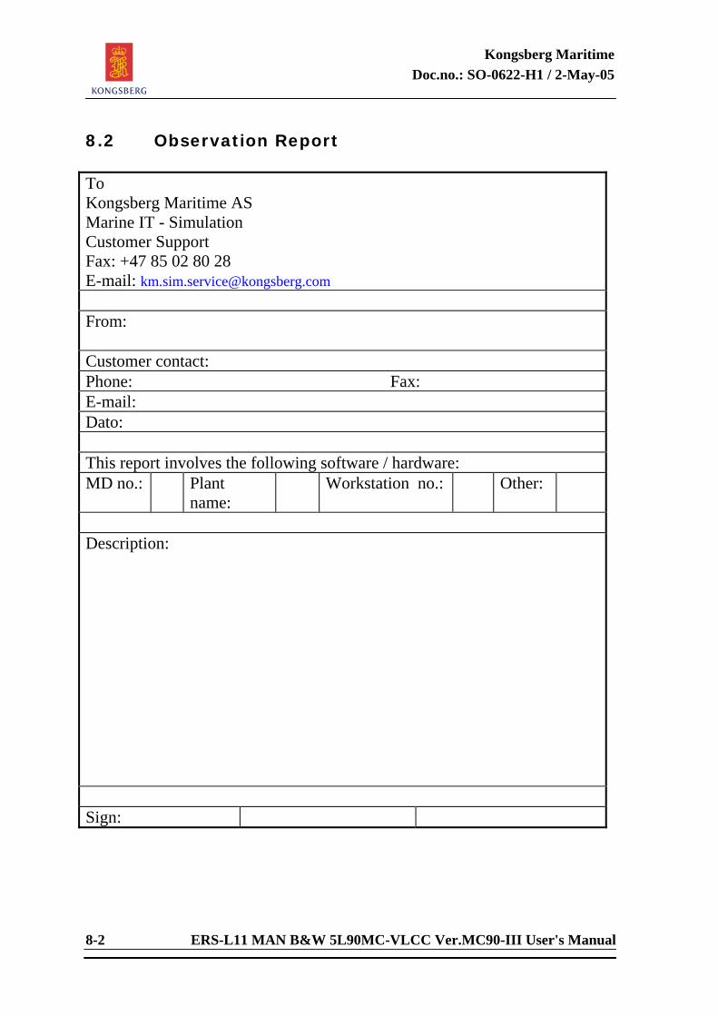
Kongsberg Maritime Doc.no.: SO-0622-H1 / 2-May-05
8-2 ERS-L11 MAN B&W 5L90MC-VLCC Ver.MC90-III User's Manual
8.2 Observation Report To Kongsberg Maritime AS Marine IT - Simulation Customer Support Fax: +47 85 02 80 28 E-mail: [email protected] From: Customer contact: Phone: Fax: E-mail: Dato: This report involves the following software / hardware: MD no.: Plant
name: Workstation no.: Other:
Description: Sign: