mca501: wireless and mobile technology
TRANSCRIPT

MCA501: Wireless and Mobile Technology
By:
Ms. Mrunal Bhogte
Asst.Prof., TIMSCDR

Syllabus
1. Wireless Technology Fundamentals
Introduction to Mobile and wireless communications, Overview of
radio transmission frequencies, Signal Antennas, Signal
Propagation, Multiplexing – SDM,FDM, TDM,CDM, Modulation –
ASK,FSK,PSK, Advanced FSK, Advanced PSK, OFDM, Spread
Spectrum – DSSS,FHSS, Wireless Transmission Impairments – Free
Space Loss, Fading, Multipath Propagation, Atmospheric
Absorption, Error Correction – Reed Solomon, BCH, Hamming
code, Convolution Code (Encoding and Decoding)
2 .Wireless Networks
Wireless network, Wireless network Architecture, Classification of
wireless networks – WBAN, WPAN, WLAN, WMAN, WWAN.
IEEE 802.11, IEEE 802.16, Bluetooth – Standards, Architecture and
Services
3. Cellular wireless Networks
Principles of cellular networks – cellular network organization,
operation of cellular systems, Handoff.
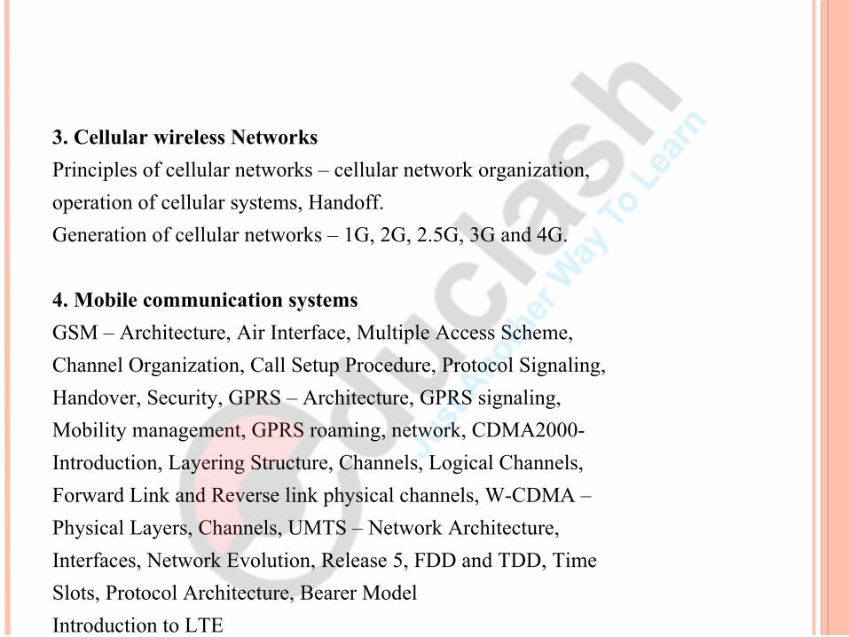
Generation of cellular networks – 1G, 2G, 2.5G, 3G and 4G.
4. Mobile communication systems
GSM – Architecture, Air Interface, Multiple Access Scheme,
Channel Organization, Call Setup Procedure, Protocol Signaling,
Handover, Security, GPRS – Architecture, GPRS signaling,
Mobility management, GPRS roaming, network, CDMA2000-
Introduction, Layering Structure, Channels, Logical Channels,
Forward Link and Reverse link physical channels, W-CDMA –
Physical Layers, Channels, UMTS – Network Architecture,
Interfaces, Network Evolution, Release 5, FDD and TDD, Time
Slots, Protocol Architecture, Bearer Model
Introduction to LTE

5 . Mobile Network Layer
Mobile IP – Dynamic Host Configuration Protocol, Mobile Ad Hoc
Routing Protocols– Multicast routing
6. Mobile Transport Layer
TCP over Wireless Networks – Indirect TCP – Snooping TCP –
Mobile TCP – Fast Retransmit / Fast Recovery
Transmission/Timeout Freezing-Selective Retransmission –
Transaction Oriented TCP , TCP over 2.5 / 3G wireless Networks
7. Application Layer
WAP Model- Mobile Location based services -WAP Gateway –
WAP protocols – WAP user agent profile, Caching model-wireless
bearers for WAP - WML – WMLScripts – WTA.

Module 1: Wireless Technology Fundamentals
1. Introduction to Mobile and wireless communications:
Network
Communication
Waveform: Changes in a recorded signal’s amplitude over the duration of time. Sine, square, triangle, sawtooth waveform.

Signals: Signals are the physical representation of data. Users of a communication system can only exchange data
through the transmission of signals.
Amplitude: Height/ Force/ Power of the wave.
Frequency: No. of cycles of waveforms per sec. Periodicity in some event.

Phase: Two or more waveforms not exactly aligned together with
same frequency and wavelength.
Wavelength: Distance travelled by an electromagnetic wave during the
time of one cycle.
Spectrum: Representation of a signal in frequency domain.
Electromagnetic waves: Travel a long distance through free space. Sinusoidal waves. Radio Frequency waves.

Electromagnetic Spectrum: Range of frequencies over which EM waves travel for
different applications.
Bandwidth: Portion of Electromagnetic Spectrum occupied by a signal.
International Telecommunications unit (ITU).

Typical Communication System: Input Signal Input Transducer Transmitter Communication channel: Wired/ Wireless Noise Receiver Output Transducer

Classification of Communication Systems: Simplex, Half duplex, Full duplex. Analog, Digital. Baseband Transmission, Transmission based on modulation.
Modulation: Modulating and carrier signal. carrier signal: High frequency sinusoidal signal.
Multiplexing: Combining several message signals together and send them
over the same communication channel. Possible only with Modulation.

Wireless Communication Systems: Uses free space. Uses EM waves. Antenna: Sender and Receiver side.
Types:Radio wave TransmissionMicrowave TransmissionMobile Cellular NetworksInfraredAirplane to Airplane NetworkUnderwater acoustic signal transmission
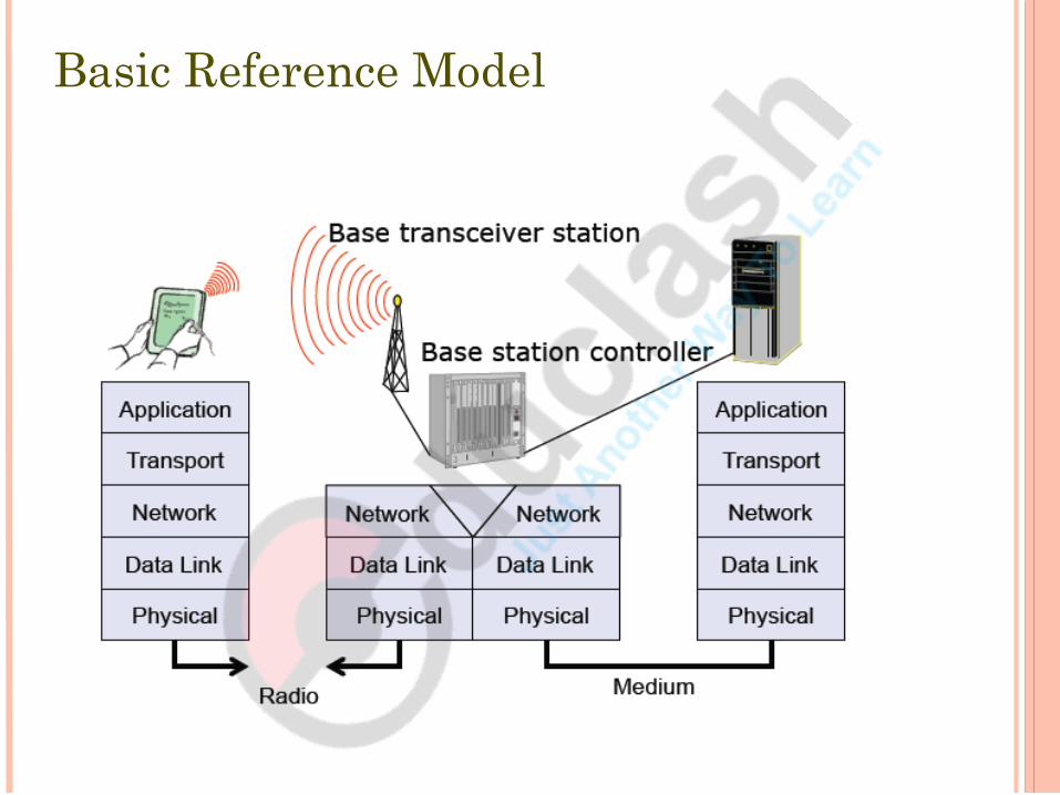
Basic Reference Model

Physical layer: conversion of stream of bits into signal, carrier generation,
frequency selection, signal detection, encryption
Data link layer: accessing the medium –multiplexing - error correction – synchronization
Network layer: routing packets – addressing -handover between networks
Transport layer: establish an end-to-endconnection – quality of service – flow andcongestion control
Application layer: service location – supportmultimedia – wireless access to www

Electromagnetic Waves
Electromagnetic radiation (EMR) takes the form of self propagating waves in a vacuum or in matter.
It consists of electric and magnetic field components which oscillate in phase perpendicular to each other and perpendicular to the direction of energy propagation.
A wave is a disturbance that propagates through space and time, usually with transference of energy.
The wavelength (denoted as λ) is the distance between two sequential crests.
The period T is the time for one complete cycle for an oscillation of a wave.
The frequency f is how many periods per unit time (for example one second) and is measured in hertz: f=1/T.
The velocity of a wave is the velocity at which variations in the shape of the wave's amplitude propagate through space: v = λ*f.

Wave propagation
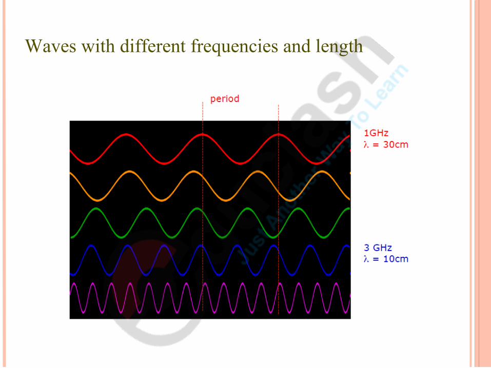
Waves with different frequencies and length

2. Frequencies for Radio Transmission

Frequency Spectrum


Signals
Signals are a function of time and location.
Physical representation of data.
Users can exchange data through the transmission of signals.
The Layer 1 is responsible for conversion of data, i. e., bits, into signals and vice-versa.
Signal parameters of periodic signals: period T, frequency f=1/T, amplitude A, phase shift ϕ.
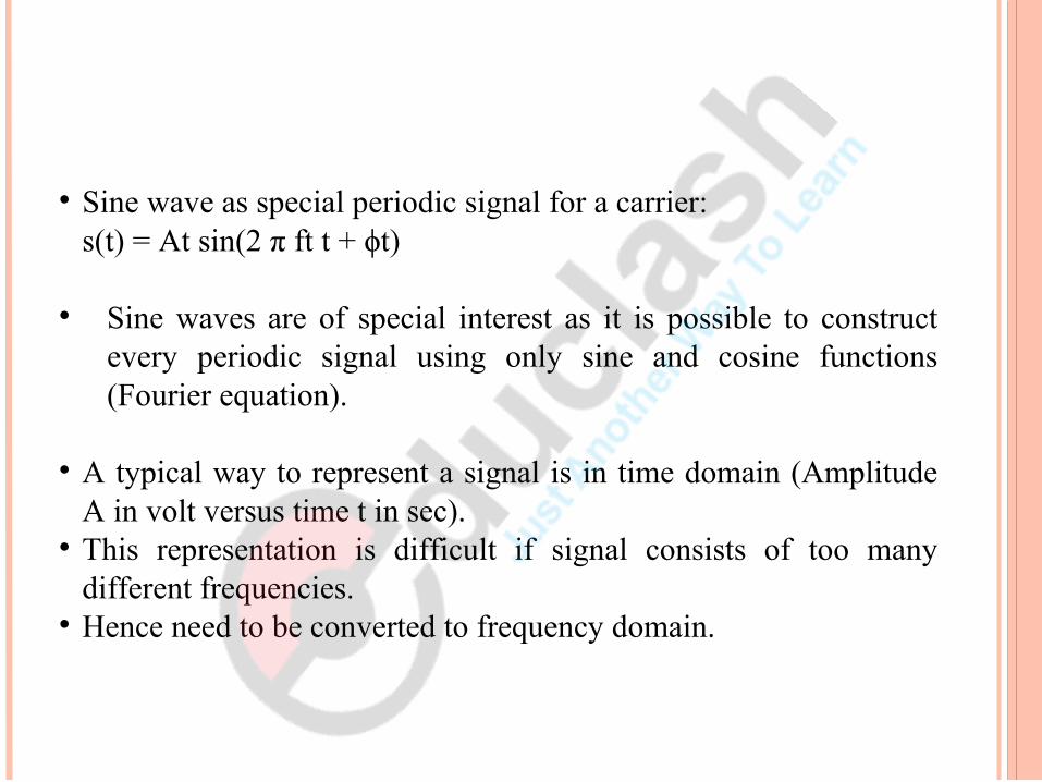
Sine wave as special periodic signal for a carrier:s(t) = At sin(2 π ft t + ϕt)
Sine waves are of special interest as it is possible to construct every periodic signal using only sine and cosine functions (Fourier equation).
A typical way to represent a signal is in time domain (Amplitude A in volt versus time t in sec).
This representation is difficult if signal consists of too many different frequencies.
Hence need to be converted to frequency domain.

3. Signal Antennas
An antenna is a transducer which converts electric power into electromagnetic waves. Transmission - radiates electromagnetic energy into
space. Reception - collects electromagnetic energy from space.
In two-way communication, the same antenna can be used for transmission and reception.
They couple electromagnetic energy to and from space.

Radiation pattern Graphical representation of radiation properties of an
antenna. Depicted as two-dimensional cross section.
Beam width (or half-power beam width) Measure of directivity of antenna. Beam width is the aperture angle from where most of the
power is radiated.
Reception pattern Receiving antenna’s equivalent to radiation pattern.

Isotropic antenna
Radiates power equally in all directions.- Omni-directional radiation
pattern.
Practically not possible.
Every antenna will have a directive effect.- intensity of radiation is
not same in all directions from the antenna.

Dipole antennas
Simplest realistic antenna.
Thin, center-fed dipole consisting of two collinear conductors of equal length, separated by a feeding gap.
Omni- directional radiation pattern in one plane and figure eight pattern in other two planes.
Half-wave dipole antenna (or Hertz antenna): If length of dipole is half the wavelength.
Quarter-wave vertical antenna (or Marconi antenna): Length of the dipole is quarter of the wavelength.

Directional antennas and sectorized antenna
Directional antennas:
With certain fixed preferential transmission and reception directions.
Useful when antenna is positioned in a valley or between the buildings.
Sectorized antennas:
Several directed antennas combined together on a single pole .
A cell can be sectorized into three or six sectors- frequency reuse.

Multi-element antenna arrays and Smart Antennas
Multi-element antenna arrays:
Two or more antennas combined together to improve reception by counteracting the negative effects of multi-path propagation.
Smart Antennas: Combine multiple antenna elements (antenna arrays) with
signal processing to optimize radiation pattern in response to the signal environment.
They can adapt to changes in reception power, transmission conditions and many signal propagation effects.

Antenna gain:Power output, in a particular direction, compared to that produced in any
direction by a perfect omni- directional antenna (isotropic antenna).
Effective area:
Related to physical size and shape of antenna.
Relationship between antenna gain and effective area:
Where, G = antenna gain
Ae = effective area
f = carrier frequency
c = speed of light (» 3 ´ 108 m/s)
= carrier wavelength
G=4 πAeλ2
=4 πf 2 Aec2

4. Signal Propagation
Transmission range : Within a certain radius of the sender, transmission is possible, i. e., a receiver receives the signals with an error rate low enough to be able to communicate and can also act as a sender.
Detection range: Within a second radius, detection of the transmission is possible, i. e., the transmitted power is large enough to differ from background noise. However, the error rate is too high to establish communication.
Interference range: Within a third even larger radius, the sender may interfere with other transmission by adding to the background noise. A receiver will not be able to detect the signals, but the signals may disturb other signals.
Propagation Modes (based on frequency):
Ground-wave propagation
Sky-wave propagation
Line-of-sight propagation

Antenna gain:Power output, in a particular direction, compared to that produced in any
direction by a perfect omni- directional antenna (isotropic antenna).
Effective area:
Related to physical size and shape of antenna.
Relationship between antenna gain and effective area:
Where, G = antenna gain
Ae = effective area
f = carrier frequency
c = speed of light (» 3 ´ 108 m/s)
= carrier wavelength
G=4 πAeλ2
=4 πf 2 Aec2

Ground Wave Propagation
Waves with low frequencies follow the earth’s surface and can propagate long distances.
Frequencies up to 2MHz. These waves are used for, e. g., submarine communication or AM
radio.

Sky Wave Propagation
Signal reflected from ionized layer of atmosphere back down to earth.
Signal can travel a number of hops, back and forth between ionosphere and earth’s surface.
Reflection effect caused by refraction. Frequencies between 2 MHz to 30MHz. Examples
Amateur radio CB radio

Line of Sight Propagation
Transmitting and receiving antennas must be within line of sight. Mobile phone systems, satellite systems, cordless telephones etc.
use even higher frequencies. The emitted waves follow a (more or less) straight line of sight.
Satellite communication – signal above 30 MHz not reflected by ionosphere.
Ground communication – antennas within effective line of site due to refraction.
Refraction – bending of microwaves by the atmosphere
Velocity of electromagnetic wave is a function of the density of the medium.
When wave changes medium, speed changes.
Wave bends at the boundary between mediums.

Optical line of sight
Effective, or radio, line of sight
d = distance between antenna and horizon (km)
h = antenna height (m)
K = adjustment factor to account for refraction, rule of thumb K = 4/3
Maximum distance between two antennas for LOS propagation:
h1 = height of antenna one
h2 = height of antenna two
d=3.57√h
d=3.57√Κh
3 .57 (√Κh1+√Κh2)

5. Wireless Transmission Impairments
Free Space loss
Blocking/Shadowing
Reflection, Refraction, Scattering, Diffraction
Multi-path Propagation.
Delay spread
Inter-symbol Interference (ISI)
Fading
Short term
Long term

Free Space loss:
Strength of signal falls off with distance over transmission medium.
Attenuation factors for unguided/wireless media: Received signal must have sufficient strength so that
circuitry in the receiver can interpret the signal. Signal must maintain a level sufficiently higher than noise
to be received without error. Attenuation is greater at higher frequencies, causing
distortion.

Free space loss, ideal isotropic antenna:
Where,Pt = signal power at transmitting antennaPr = signal power at receiving antenna
= carrier wavelengthd = propagation distance between antennasc = speed of light (» 3 ´ 10 8 m/s)where d and are in the same units (e .g., meters)
PtP r
=(4 πd )2
λ2=
(4 πfd )2
c2

Blocking/Shadowing
An extreme form of attenuation is blocking or shadowing of radio signals due to large obstacles.
Reflection:
If an object is large compared to the wavelength of the signal, e.g., huge buildings, mountains, or the surface of the earth, the signal is reflected. The reflected signal is not as strong as the original, as objects can absorb some of the signal’s power.
Refraction:
This effect occurs because the velocity of the electromagnetic waves depends on the density of the medium through which it travels.

Scattering:
If the size of an obstacle is in the order of the wavelength or less, then waves can be scattered An incoming signal is scattered into several weaker outgoing signals.
Diffraction:Radio waves will be deflected at an edge and propagate in different directions.
The result of scattering and diffraction are patterns with varying signal strengths depending on the location of the receiver.
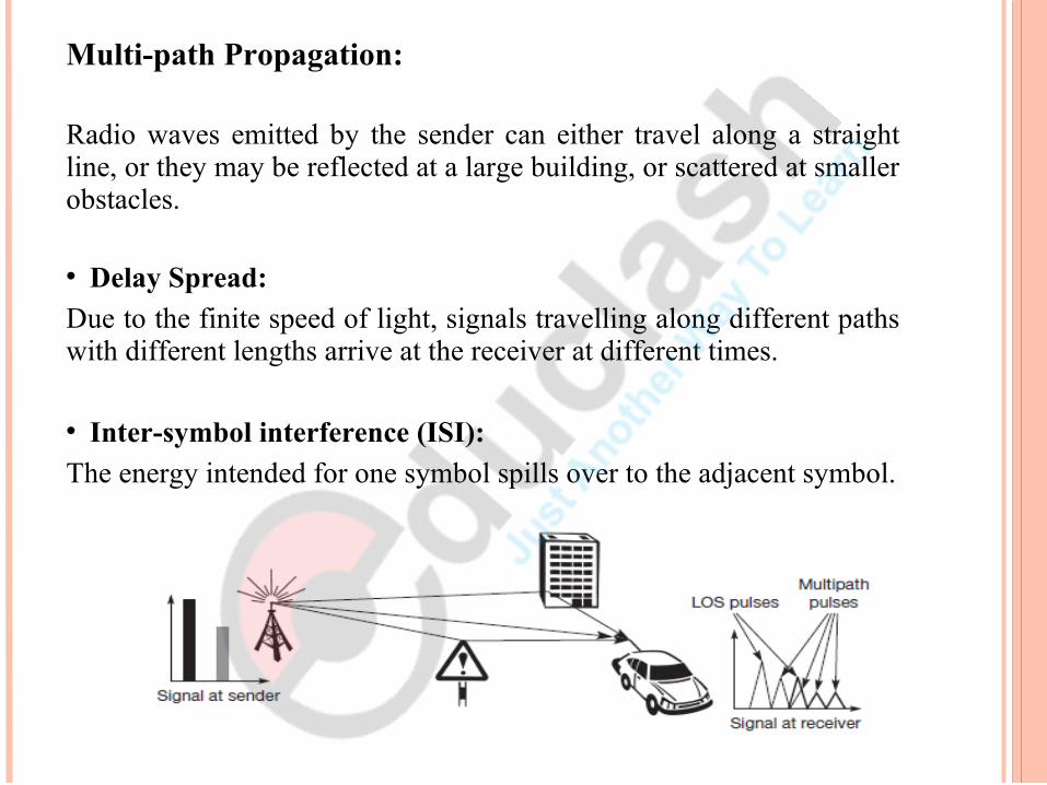
Multi-path Propagation:
Radio waves emitted by the sender can either travel along a straight line, or they may be reflected at a large building, or scattered at smaller obstacles.
Delay Spread:
Due to the finite speed of light, signals travelling along different paths with different lengths arrive at the receiver at different times.
Inter-symbol interference (ISI):
The energy intended for one symbol spills over to the adjacent symbol.

Fading:
If receivers, or senders, or both, move. Then the channel characteristics change over time, and the paths a signal can travel along vary.
The power of the received signal changes considerably over time. These quick changes in the received power are called as short-term fading.
Long term fading- average power over time, is caused by, for example, varying distance to the sender or more remote obstacles.

6. Multiplexing
Multiplexing describes how several users can share a medium with minimum or no interference.
For wireless communication, multiplexing can be carried out in four dimensions: space, time, frequency, and code.
In this field, the task of multiplexing is to assign space, time, frequency, and code to each communication channel with a minimum of interference and a maximum of medium utilization.
Types:
Space division multiplexing (SDM)
Frequency division multiplexing (FDM)
Time division multiplexing (TDM)
Code division multiplexing (CDM)

Space division multiplexing (SDM):
Each channel has its own space with the dimensions of code c, time t and frequency f. Each channel has its interference range.
The space between the interference ranges is sometimes called guard space.
SDM implies a separate sender for each communication channel with a wide enough distance between senders.
e.g. FM radio stations. Drawbacks:
Waste of space. If two or more channels are established within
the same space.

Frequency division multiplexing (FDM):
Subdivide the frequency dimension into several non-overlapping frequency bands.
Each channel is allotted its own frequency band. Guard spaces are needed to avoid frequency band overlapping (also called
adjacent channel interference). e.g. radio stations within the same region, where each radio station has its own
frequency. Does not need complex coordination between sender and receiver: the receiver
only has to tune in to the specific sender. Drawbacks:
tremendous waste of (scarce) frequency
resources. very inflexible. limits the number of senders.

Time division multiplexing (TDM):
A channel is given the whole bandwidth for a certain amount of time, i.e., all senders use the same frequency but at different points in time.
Guard spaces, which represent time gaps, have to separate the different periods when the senders use the medium.
If two transmissions overlap in time, this is called co-channel interference.
Precise synchronization between different senders is necessary.
Advantage: Scheme is quite flexible as one can assign more sending time to senders with a heavy load and less to those with a light load.
Disadvantage: All senders need precise clocks or, alternatively, a way has to be found to distribute a synchronization signal to all senders.

Combined Frequency and Time division multiplexing: A channel can use a certain frequency band for a certain amount of time.
Guard spaces are needed both in the Time and in the Frequency Dimension.
The mobile phone standard GSM uses this combination of frequency and time division multiplexing for transmission between a mobile phone and a base station.
More robust against frequency selective interference, i.e., interference in a certain small frequency band.
Provides some (weak) protection against tapping, as in this case the sequence of frequencies a sender uses has to be known to listen in to a channel.
Drawback: necessary coordination between different senders.

Code division multiplexing (CDM):
Channels use the same frequency at the same time for transmission. Separation is achieved by assigning each channel its own ‘code’, guard spaces are
realized by using codes with the necessary ‘distance’ in code space, e. g., orthogonal codes.
CDM has built-in security. By using a secret code a secure channel can be established in a ‘hostile’
environment. Advantages:
Gives good protection against interference and tapping. Different codes have to be assigned, but code space is huge compared to the
frequency space. Assigning individual codes to each sender does not usually cause problems.
Drawback: relatively high complexity of the receiver.• To apply CDM, precise power control is required.

References:
Mobile Communications, Second Edition, Jochen Schiller, Pearson Education- Chapter 2.

University Questions:
1.Write a short note on Antennas.- May 16- 5M
2. Discuss the following impairments in wireless environment.- Atmospheric Absorption, Multipath Propagation, Fading.- Nov 16- 7M