mccbs and trip-free switches x160
TRANSCRIPT

Description Rating In Catalogue No.
3P 4P
MCCBs x160 18kA
breaking capacity
Ics : 18 kA
(400/415 V AC)
fixed thermal
1x In
fixed magnetic
> 10 x In
adjustable thermal
0.63 - 0.8 - 1 x In
fixed magnetic
> 10 x In
16A
20A
25A
32A
40A
50A
63A
80A
100A
125A
160A
25A
40A
63A
80A
100A
125A
160A
HDA016Z
HDA020Z
HDA025Z
HDA032Z
HDA040Z
HDA050Z
HDA063Z
HDA080Z
HDA100Z
HDA125Z
HDA160Z
HDA025U
HDA040U
HDA063U
HDA080U
HDA100U
HDA125U
HDA160U
HDA017Z
HDA021Z
HDA026Z
HDA033Z
HDA041Z
HDA051Z
HDA064Z
HDA081Z
HDA101Z
HDA126Z
HDA161Z
HDA026U
HDA041U
HDA064U
HDA081U
HDA101U
HDA126U
HDA161U
MCCBs x160 25kA
breaking capacity
Ics : 20 kA
(400/415 V AC)
fixed thermal
1x In
fixed magnetic
> 10 x In
adjustable thermal
0.63 - 0.8 - 1 x In
fixed magnetic
> 10 x In
16A
20A
25A
32A
40A
50A
63A
80A
100A
125A
160A
25A
40A
63A
80A
100A
125A
160A
HHA016Z
HHA020Z
HHA025Z
HHA032Z
HHA040Z
HHA050Z
HHA063Z
HHA080Z
HHA100Z
HHA125Z
HHA160Z
HHA025U
HHA040U
HHA063U
HHA080U
HHA100U
HHA125U
HHA160U
HHA017Z
HHA021Z
HHA026Z
HHA033Z
HHA041Z
HHA051Z
HHA064Z
HHA081Z
HHA101Z
HHA126Z
HHA161Z
HHA026U
HHA041U
HHA064U
HHA081U
HHA101U
HHA126U
HHA161U
HDA125Z
HDA161U
Moulded case circuit breakers
x160
Available in 3P and 4P
Mechanical test button, lockable
settings,
integrated padlocking handle
Ø 4mm,
Thermal magnetic trip unit, 2
versions:
• Z version: fixed thermal and
fixed magnetic
• U version: adjustable thermal
and fixed magnetic
DIN rail adaptor available for DIN
rail mounting
Connection capacity
95 mm2 rigid cables
70 mm2 flexible cables collar
terminals
Comply with IEC 60947-2
Trip-free switches
Allows tripping at distance using
a voltmetrical trip unit (optional)
AC22/23A
Comply with IEC60947-3
MCCBs and trip-free switches x160

Description In Catalogue No.
3P 4P
MCCBs x160 40kA
adjustable thermal
0.63 - 0.8 - 1 x In
fixed magnetic
> 10 x In
25A
40A
63A
80A
100A
125A
160A
HNA025U
HNA040U
HNA063U
HNA080U
HNA100U
HNA125U
HNA160U
HNA026U
HNA041U
HNA064U
HNA081U
HNA101U
HNA126U
HNA161U
Trip-free switches x160
suitable for
AC22A / AC 23A
Ue: 415 V AC
Icw (1s): 2 kA
125A
160A
HCA125Z
HCA160Z
HCA126Z
HCA161Z
HNA125Z
Add-on blocks
lΔn 300 mA
fixed sensitivity
instantaneous tripping
sensitivity lΔn
adjustable: 0.03 - 0.1 - 0.3 - 1 -
3 - 6A
adjustable tripping:
- instantaneous
- time delay: 0.06 - 0.15 - 0.3 -
0.5 - 1s
125 A
125A
160A
HBA128H
HBA126H
HBA161H
HBA127H
HBA125H
HBA160H
HBA161H
MCCBs and trip-free switches x160
Add-on blocks for x160 devices
These devices are intended to be
fixed on the right side of the
devices.
Type A and HI
For fault component pulsating
current.
HI (High Immunity):
the products with “reinforced
immunity” reduce the
unexpected tripping when they
protect equipment generating
disturbances (micro-processing,
electronic ballast...)
Fixed version: 300 mA sensitivity
and instantaneous tripping
Adjustable version: adjustable
sensitivity and tripping.
Test button for differential
functioning check.
Mechanical test button
LED or at distance signal for
tripping or advance warning
(25-50% IΔn).
Assembly and disassembly
facilitated by the drawer
assembly system. The terminal
cover is dependent of the add-
on block.
Connection capacity
95 mm2 rigid cables
70 mm2 flexible cables
Comply with IEC 60947-2
annexe B.

Description Characteristics
Auxiliary contacts
AX
AL
1 changeover contact (ON/OFF)
250 V AC / 3A
125 V DC / 0,4A
1 NO + 1 NC
1 changeover alarm contact
250 V AC / 3A
125 V DC / 0,4A
1 NO + 1 NC
HXA021H
HXA024H
Shunt trips
SH
24 V DC HXA001H
Undervoltage releases
UV
24 V DC
200 - 240 V AC
380 - 450 V AC
HXA011H
HXA014H
HXA015H
Catalogue
No.
HXA024HHXA021H
HXA014H
Accessories for MCCBs and trip-free switches x160
Indication contacts
• 1 changeover switch (ON/OFF):
indicates the position of the
MCCB is “open” or “close”.
• 1 changeover alarm contact:
indicates MCCB tripping.
Coil connection
Connection capacity:
0,75 mm2 flexible or rigid cables
Optional connection cables.
The cable capacity of the
terminals is 0.5 to 1.25 mm2.
Shunt trip
Remotes tripping of MCCBs or
trip-free switches. Operating
voltage: 0.7 to 1.1 x Un
Under voltage release
Allows the tripping of MCCBs or
trip-free switches when voltage
level drop between 35 and 70% of
Un. Pick up voltage 0.85 x Un
Direct rotary handle
• padlockable
• equipped with front cover and
handle
• fixing without any additional
screw
Extended rotary handle
• IP 55
• supplied complete with shaft
and handle
200 - 240 V AC HXA004H
Locking kit HXA035H

Description Characteristics Catalogue No.
3P 4P
Extended connections set of 3 or 4 spreader
connections
HYA015HHYA014H
Interphase barriers set of 3,
height: 50 mm
set of 3,
height: 97 mm
HYA019H
HYB019H
HYA019H
HYB019H
Din rail adaptor HYA033HHYA033H
HYA015H
Direct rotary handle padlockable handle
max Ø 6 mm
HXA030H
Extended rotary handle padlockable handle
max Ø 8 mm
HXA031H
HXA030H
HXA030H
HXA031H
HXA031H
Accessories for MCCBs and trip-free switches x160
Description In Catalogue No.
3P 4P
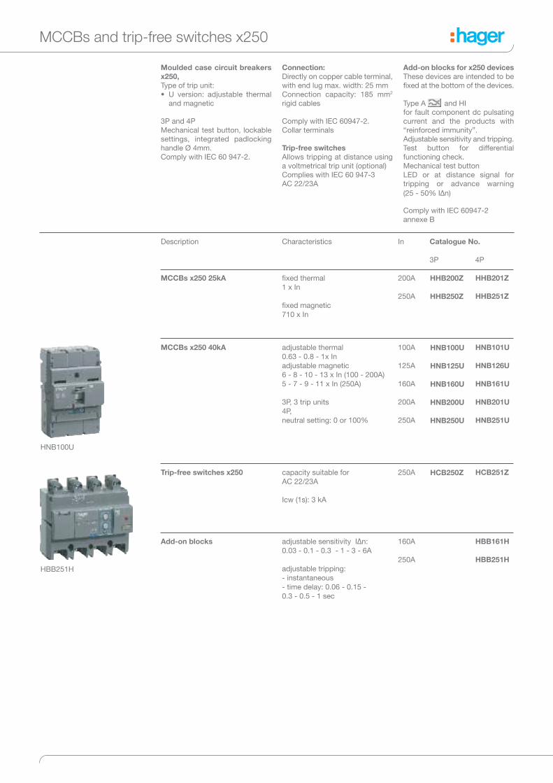
MCCBs x250 40kA 100A
125A
160A
200A
250A
HNB100U
HNB125U
HNB160U
HNB200U
HNB250U
HNB101U
HNB126U
HNB161U
HNB201U
HNB251U
Trip-free switches x250 250A HCB250Z HCB251Z
Characteristics
adjustable thermal
0.63 - 0.8 - 1x In
adjustable magnetic
6 - 8 - 10 - 13 x In (100 - 200A)
5 - 7 - 9 - 11 x In (250A)
3P, 3 trip units
4P,
neutral setting: 0 or 100%
capacity suitable for
AC 22/23A
Icw (1s): 3 kA
HNB100U
Add-on blocks 160A
250A
HBB161H
HBB251H
adjustable sensitivity IΔn:
0.03 - 0.1 - 0.3 - 1 - 3 - 6A
adjustable tripping:
- instantaneous
- time delay: 0.06 - 0.15 -
0.3 - 0.5 - 1 sec
HBB251H
MCCBs and trip-free switches x250
Moulded case circuit breakers
x250,
Type of trip unit:
• U version: adjustable thermal
and magnetic
3P and 4P
Mechanical test button, lockable
settings, integrated padlocking
handle Ø 4mm.
Comply with IEC 60 947-2.
Connection:
Directly on copper cable terminal,
with end lug max. width: 25 mm
Connection capacity: 185 mm2
rigid cables
Comply with IEC 60947-2.
Collar terminals
Trip-free switches
Allows tripping at distance using
a voltmetrical trip unit (optional)
Complies with IEC 60 947-3
AC 22/23A
Add-on blocks for x250 devices
These devices are intended to be
fixed at the bottom of the devices.
Type A and HI
for fault component dc pulsating
current and the products with
“reinforced immunity”.
Adjustable sensitivity and tripping.
Test button for differential
functioning check.
Mechanical test button
LED or at distance signal for
tripping or advance warning
(25 - 50% I∆n)
Comply with IEC 60947-2
annexe B
MCCBs x250 25kA 200A
250A
HHB201Z
HHB251Z
fixed thermal
1 x In
fixed magnetic
710 x In
HHB200Z
HHB250Z

Description Characteristics
Auxiliary contacts
AX
AL
1 changeover contact
250 V AC / 3A
125 V DC / 0,4A
1 NO + 1 NC
1 changeover alarm contact
250 V AC / 3A
125 V DC / 0,4A
1 NO + 1 NC
HXA021H
HXA024H
Shunt trips
SH
24 V DC HXA001H
Undervoltage releases UV 24 V DC
200 - 240 V AC
380 - 450 V AC
HXA011H
HXA014H
HXA015H
Direct rotary handles padlockable handle
max Ø 6 mm
HXB030H
Extended rotary handles padlockable handle
max Ø 8 mm
HXB031H
Catalogue
No.
Motor operators 230 - 240V AC HXB042H
HXA024HHXA021H
HXA014H
HXB042H
Indication contacts
• 1 changeover switch (ON/OFF):
indicates the position of the
MCCB is “open” or “closed”.
• 1 changeover alarm contact:
indicates MCCB tripping.
Coil connection
Connection capacity:
0.75 mm2 flexible or rigid cables
Optional connection cables.
The cable capacity of the
terminals is 0.5 to 1.25 mm2.
Shunt trip
Remotes tripping of MCCBs or
trip-free switches.
Operating voltage: 0.7 to 1.1 x Un
Under voltage release
Allows the tripping of MCCBs or
trip-free switches when voltage
level drop between 35 and 70% of
Un. Pick up voltage 0.85 x Un
Direct rotary handle
• padlockable
• equipped with front cover and
handle
• fixing without any additional
screw
Extended rotary handle
• IP 55
• supplied complete with shaft
and handle
Accessories for MCCBs and trip-free switches x250
200 - 240 V AC HXA004H
Extended
connections
spreaders HYB012HHYB011H
Interphase
barriers
set of 3
height: 97 mm
HYB019H
(3P) (4P)
Mechanical
Inter lock kit
HXB065H
Description In Catalogue No.
3P 4P
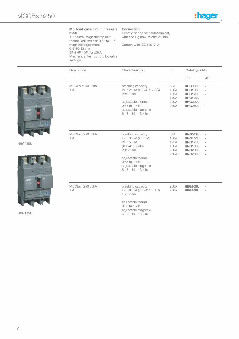
MCCBs h250 25kA
TM
63A
100A
125A
160A
200A
250A
HHG063U
HHG100U
HHG125U
HHG160U
HHG200U
HHG250U
Characteristics
breaking capacity
Icu : 25 kA (400/415 V AC)
Ics: 19 kA
adjustable thermal
0.63 to 1 x In
adjustable magnetic
6 - 8 - 10 - 13 x In
MCCBs h250 50kA
TM
63A
100A
125A
160A
200A
250A
HNG063U
HNG100U
HNG125U
HNG160U
HNG200U
HNG250U
breaking capacity
Icu : 30 kA (20-32A)
Icu : 50 kA
(400/415 V AC)
Ics: 25 kA
adjustable thermal
0.63 to 1 x In
adjustable magnetic
6 - 8 - 10 - 13 x In
MCCBs h250 65kA
TM
200A
250A
HEG200U
HEG250U
breaking capacity
Icu : 65 kA (400/415 V AC)
Ics: 36 kA
adjustable thermal
0.63 to 1 x In
adjustable magnetic
6 - 8 - 10 - 13 x In
HHG250U
-
-
-
-
-
-
-
-
-
-
-
-
-
-
MCCBs h250
Moulded case circuit breakers
h250
• Thermal magnetic trip unit:
thermal adjustment: 0.63 to 1 In
magnetic adjustment:
6-8-10-13 x In
3P & 4P / 3P (for 25kA)
Mechanical test button, lockable
settings,
Connection:
Directly on copper cable terminal,
with end lug max. width: 25 mm
Comply with IEC 60947-2
HNG125U

Description In Catalogue No.
3P 4P
Characteristics
MCCBs h250 70kA
LSI
40A
125A
250A
HEC040U
HEC125U
HEC250U
HEC041U
HEC126U
HEC251U
breaking capacity
Icu : 70 kA (400/415 V AC)
Ics: 70 kA
adjustable overload
Ir = 0.4 to 1 x In
adjustable short circuit
2.5 to 10 x Ir
3P, 3 trip units & 4P, 3 trip units
MCCBs h250 50kA
LSI
40A
125A
250A
HNC040U
HNC125U
HNC250U
HNC041U
HNC126U
HNC251U
breaking capacity
Icu : 50 kA (400/415 V AC)
Ics: 25 kA
adjustable overload
Ir = 0.4 to 1 x In
adjustable short circuit
2.5 to 10 x Ir
3P, 3 trip units & 4P, 3 trip units
HNC125U
Moulded case circuit breakers
h250
• Electronic trip unit LSI:
L - Long time delay - protection
against overloads:
adjustable: Ir from 0.4 to 1 x In
S - Short time delay - protection
against short-circuits: adjustable
Isd from 2.5 to 10 x Ir
time delay 0.1 or 0.2 s I
Instantaneous - definitive time
delay tripping maximum
threshold in case of short-circuit
(Ii max = 13 x In)
2 values setting:
• Ir setting
• predefined curve selection
(9 possibilities)
3P3d and 4P3d/4dN/2
(adjustable neutral
0 - 50 - 100%)
Mechanical button,
Sealable settings.
Not for use in TPN and panel
boards.
Connection:
Directly on copper cable
terminal, with end lug max.
width: 25 mm
Comply with IEC 60947-2.
MCCBs h250
HEC250U

Description Characteristics
Auxiliary contacts
AX
AL
1 changeover contact
250 V AC / 3A
125 V DC / 0,4A
1 NO + 1 NC
1 changeover alarm contact
250 V AC / 3A
125 V DC / 0,4A
1 NO + 1 NC
HXC021H
HXC024H
Shunt trips
SH
24 V DC
200 - 240 V AC
HXC001H
HXC004H
Undervoltage releases UV 24 V DC
200 - 240 V AC
380 - 450 V AC
HXC011H
HXC014H
HXC015H
Direct rotary handles padlockable handle
Ø 5 - 8 mm2 max
HXC030H
Extended rotary handles padlockable handle
Ø 5 - 8 mm2 max
HXC031H
Catalogue
No.
HXC004H
HXC021H HXC024H
HXC014H
HXC030H
Accessories for MCCBs h250
Indication contacts
• 1 changeover switch (ON/OFF):
indicates the position of the
MCCB is “open” or “close”.
• 1 changeover alarm contact:
indicates MCCB tripping.
Coil connection
Connection capacity:
0.75 mm2 flexible or rigid cables
Optional connection cables.
The cable capacity of the
terminals is 0.5 to 1.25 mm2.
Shunt trip
Remotes tripping of MCCBs or
trip-free switches.
Operating voltage: 0.7 to 1.1 x
Un
Under voltage release
Allows the tripping of MCCBs or
trip-free switches when voltage
level drop between 35 and 70%
of Un.
Pick up voltage 0.85 x Un
Direct rotary handle
• padlockable
• equipped with front cover and
handle
• fixing without any additional
screw
Extended rotary handle
• IP 55
• supplied complete with shaft
and handle
Motor operators 230-240 V AC HXC042H
Extended
connections
spreader connections HYB012H
HYC011H
HYC011H
Interphase barriers set of 3 pieces HYC019H
(3P) (4P)
Locking kit HXC035H
Mechanical
Inter lock kit
HXC065H

Description In Catalogue No.
3P 4P
MCCBs h400 25kA
TM
400A HHD400U
Characteristics
breaking capacity
Icu : 25 kA (400/415 V AC)
Ics: 25 kA
adjustable thermal: 0.63 to 1 x In
adjustable magnetic: 6 to 12 x In
3P
MCCBs h400 50kA
TM
250A
400A
-
HND400U
HND251U
HND401U
breaking capacity
Icu : 50 kA (400/415 V AC)
Ics: 50 kA
adjustable thermal: 0.63 to 1 x In
adjustable magnetic: 6 to 12 x In
-
HHD400U
MCCBs and trip-free switches h400-h630
Moulded case circuit breakers
h400, h630
Thermal magnetic trip unit TM:
• thermal adjustment:
from 0.63 to 1 x In
• magnetic adjustment:
from 6 to 12 x In
Connection:
Directly on copper cable
terminal, with end lug max.
width: 30 mm
Comply with IEC 60947-2
HND400U

Description In Catalogue No.
3P 4P
MCCBs h630 50kA
LSI
* delivered with spreader bars
400A
630A
HND400H
HND630U*
HND401H
HND631U*
Characteristics
breaking capacity
Icu : 50 kA (400/415 V AC)
Ics: 50 kA
adjustable overload: Ir = 0.4 to 1 x In
adjustable short circuit:
2.5 to 10 x Ir (250-400A)
2.5 to 8 x Ir (630A)
time delay: 0.1 - 0.2 s
MCCBs h630 70kA
LSI
* delivered with spreader bars
400A
630A
HED400U
HED630U*
HED401U
HED631U*
breaking capacity
Icu : 70 kA (400/415 V AC)
Ics: 50 kA
adjustable overload: Ir = 0.4 to 1 x In
adjustable short circuit:
2.5 to 10 x Ir (250-400A)
2.5 to 8 x Ir (630A)
time delay: 0.1 - 0.2 s
Trip-free switches
* delivered with spreader bars
400A
630A
HCD400U
HCD630U*
HCD401U
HCD631U*
suitable for AC 22A / AC 23A
Ue: 415 V AC
Icw (0.3s) = 5kA
HND630U
Add-on blocks
(only for h630)
400A
500A
-
-
HBD401H
HBD631H
adjustable sensitivity lΔn:
0.03 - 0.1 - 0.3 - 1 - 3 - 6A
adjustable tripping
instantaneous
time delay: 0.06s - 0.15s - 0.3s -
0.5 - 1s
HBD401H
Moulded case circuit breakers
h400, h630
- Electronic trip unit LSI:
L - Long time delay - protection
against overloads: adjustable: Ir
from 0,4 to 1 x In
S - Short time delay - protection
against short-circuits: adjustable
Isd from 2.5 to 10 x Ir (400A), 2.5
to 8 x Ir (630A) time delay 0.1 or
0.2 s
I - Instantaneous - definitive time
delay tripping maximum
threshold in case of short-circuit
(Ii max = 13 x In)
2 values setting:
• Ir setting
• predefined curve selection (7
possibilities)
3P3d and 4P3d/4dN/2
(adjustable neutral 0 - 50 -
100%)
Mechanical button,
Sealable settings
Connection:
Directly on copper cable
terminal, with end lug max.
width: 30 mm
Comply with IEC 60947-2
Trip-free switches
Allows tripping at distance using
a voltmetrical trip unit (optional)
Comply with IEC 60947-3
AC 23A / DC 22A
Add-on blocks
For h630 (LSI) devices
These devices are intended to be
fixed at the bottom of the
devices.
Fixed version: 300mA
sensitivity and instantaneous
tripping
Adjustable version: sensitivity
from 30mA to 6A, tripping from
instantaneous to 1s delay.
Test button for differential
functioning check.
Mechanical test button.
LED or remote signal for tripping
or advance warning (25-50%
lΔn).
Type A (for fault component DC
pulsating current) and HI
(reinforced immunity against
unexpected tripping).
Comply with IEC 60947-2
MCCBs and trip-free switches h400-h630

Description Characteristics Catalogue No.
3P 4P
Extended connections spreader connections HYD012H
HYD015H
HYD011H
HYD014H
In
250 - 400A
630A
Motor operators 100-240 V AC HXD042HHXD042H
HXD042H
Description Characteristics
Auxiliary contacts
AX
AL
1 changeover contact
250 V AC / 3A
125 V DC / 0,4A
1 NO + 1 NC
1 changeover alarm contact
250 V AC / 3A
125 V DC / 0,4A
1 NO + 1 NC
HXC021H
HXC024H
Shunt trips
SH
24 V DC
200 - 240 V AC
HXC001H
HXC004H
Undervoltage releases
UV
24 V DC
200 - 240 V AC
380 - 450 V AC
HXC011H
HXC014H
HXC015H
Catalogue
No.
HXC021H HXC024H
HXC004H
HXC014H
Direct rotary handle padlockable handle
max Ø 6 mm
HXD030H
Extended rotary handle padlockable handle
max Ø 8 mm
HXD031H
Accessories for MCCBs and trip-free switches h400-h630
Indication contacts
• 1 changeover switch (ON/OFF):
indicates the position of the
MCCB is “open” or “close”
• 1 changeover alarm contact:
indicates MCCB tripping
Coil connection
Connection capacity:
0.75 mm2 flexible or rigid cables
Optional connection cables.
The cable capacity of the
terminals is 0.5 to 1.25 mm2.
Shunt trip
Remotes tripping of MCCBs or
trip-free switches.
Operating voltage:
0.7 to 1.1 x Un
Under voltage release
Allows the tripping of MCCBs or
trip-free switches when voltage
level drop between 35 and 70%
of Un. Pick up voltage 0.85 x Un
Direct rotary handle
• padlockable
• equipped with front cover and
handle
• fixing without any additional
screw
Extended rotary handle
• IP 55
• supplied complete with shaft
and handle
Locking kit HXD039H
Mechanical Inter lock kit HXD065H

Description In Catalogue No.
3P 4P
MCCBs h1000 50kA
LSI
630A
800A
1000A
HNE630U*
HNE800U
HNE970U
HNE801U
HNE971U
MCCBs h1000 70kA
LSI
800A
1000A
HEE800U
HEE970U
HEE801U
HEE971U
Characteristics
breaking capacity
Icu : 50 kA (400/415 V AC)
Ics: 50 kA
adjustable overload
Ir = 0.4 to 1 x In
adjustable short circuit
2.5 to 10 x Ir (630 - 800A)
2.5 to 8 x Ir (1000A)
time delay: 0.1-0.2 s
neutral setting from 0-50 to
100%
* without straight extended
connection
breaking capacity
Icu : 70 kA (400/415 V AC)
Ics: 50 kA
adjustable overload
Ir = 0.4 to 1 x In
adjustable short circuit
2.5 to 10 x Ir (800A)
2.5 to 8 x Ir (1000A)
time delay: 0.1-0.2 s
neutral setting from
0-50 to 100%
Trip-free switches 800A
1000A
HCE800U
HCE970U
HCE801U
HCE971U
suitable for
AC 22A / AC 23A
Ue : 415 V AC
Icw (0.3 s) = 10 kA
HNE970U
Moulded case circuit breakers
h1000
• Electronic trip unit LSI:
L - Long time delay - protection
against overloads: adjustable: Ir
from 0,4 to 1 x In
S - Short time delay - protection
against short-circuits: adjustable
Isd from 2.5 to 10 x Ir (630-
800A), 2.5 to 8 x Ir (1000A)
time delay 0.1 or 0.2 s
I - Instantaneous - definitive time
delay tripping maximum
threshold in case of short-circuit
(Ii max = 12 x In)
2 values setting:
• Ir setting
• predefined curve selection
(7 possibilities)
3P3d and 4P3d/4dN/2
(adjustable neutral
0 - 50 - 100%)
Mechanical button,
Sealable settings
Connection
Directly on copper cable
terminal, with end lug max.
width: 50 mm
Comply with IEC 60947-2
Trip-free switches
Allows tripping at distance using
a voltmetrical trip unit (optional)
Comply with IEC 60 947-3
AC 23A / DC 22A
MCCBs and trip-free switches h1000
HEE970U

Description Characteristics
Auxiliary contacts
AX
AL
1 changeover contact
250 V AC / 3A
125 V DC / 0,4A
1 NO + 1 NC
1 changeover alarm contact
250 V AC / 3A
125 V DC / 0,4A
1 NO + 1 NC
HXC021H
HXC024H
Shunt trips
SH
24 V DC
200 - 240 V AC
HXC001H
HXC004H
Undervoltage releases UV 24 V DC
220 - 240 V AC
380 - 415 V AC
HXE011H
HXE014H
HXE015H
Catalogue
No.
HXC021H HXC024H
HXC004H
HXE014H
Indication contacts
• 1 changeover switch (ON/OFF):
indicates the position of the
MCCB is “open” or “close”
• 1 changeover alarm contact:
indicates MCCB tripping.
Coil connection
Connection capacity:
0.75 mm2 flexible or rigid cables
Optional connection cables.
The cable capacity of the
terminals is 0.5 to 1.25 mm2
Shunt trip
Remotes tripping of MCCBs or
trip-free switches.
Operating voltage:
0.7 to 1.1 x Un
Under voltage release
Allows the tripping of MCCBs or
trip-free switches when voltage
level drop between 35 and 70%
of Un. Pick up voltage 0.85 x Un
Accessories for MCCBs and trip-free switches h1000
Mechanical Inter lock kit HXE065H

Description Characteristics Catalogue No.
3P 4P
Direct rotary handles padlockable handle HXE030H
Extended rotary handles padlockable handle HXE031H
Motor operators 100 - 240V AC HXE042H
HXE030H
Interphase barriers HYE019HHYE019Hset of 3
Accessories for MCCBs and trip-free switches h1000
Direct rotary handle
• padlockable
• equipped with front cover and
handle
• fixing without any additional
screw
Extended rotary handle
• IP 55
• supplied complete with shaft
and handle

Description In Catalogue No.
3P 4P
MCCBs h1600 50kA
LSI
1250A
1600A
HNF980U
HNF990U
HNF981U
HNF991U
MCCBs h1600 70kA
LSI
1250A
1600A
HEF980U
HEF990U
HEF981U
HEF991U
Characteristics
breaking capacity
Icu : 50 kA (400/415 V AC)
Ics: 50 kA
adjustable overload
Ir = 0.4 to 1 x In
adjustable short circuit
2.5 to 10 x Ir
time delay: 0.1-0.2 s
neutral setting 0, 50, 100%
breaking capacity
Icu : 70 kA (400/415 V AC)
Ics: 50 kA
adjustable overload
Ir = 0.4 to 1 x In
adjustable short circuit
2.5 to 10 x Ir
time delay: 0.1-0.2 s
neutral setting from
0, 50, 100%
Trip-free switches 1250A
1600A
HCF980U
HCF990U
HCF981U
HCF991U
suitable for
AC 22A / AC 23A
Ue : 415 V AC
Icw (0.3 s) = 20 kA
HNF990U
Moulded case circuit breakers
h1600, selection and
protection
• Electronic trip unit LSI:
L - Long time delay - protection
against overloads: adjustable: Ir
from 0.4 to 1 x In
S - Short time delay - protection
against short-circuits: adjustable
Isd from 2.5 to 10 x Ir time delay
0.1 or 0.2 s
I - Instantaneous - definitive time
delay tripping maximum
threshold in case of short-circuit
(Ii max = 12 x In)
2 values setting:
• Ir setting
• predefined curve selection
(7 possibilities)
3P3d and 4P3d/4dN/2
(adjustable neutral
0 - 50 - 100%)
Mechanical button,
Sealable settings
Connection:
Directly on copper cable
terminal, with end lug max.
width: 60 mm
Comply with IEC 60947-2
Trip-free switches
Allows tripping at distance using
a voltmetrical trip unit (optional)
Comply with IEC 60947-3
AC 23A / DC 22A
MCCBs and trip-free switches h1600
HNF990U

Description Characteristics
Auxiliary contacts
AX
AL
1 changeover contact
250 V AC / 3A
125 V DC / 0.4A
1 NO + 1 NC
1 changeover alarm contact
250 V AC / 3A
125 V DC / 0.4A
1 NO + 1 NC
HXC021H
HXC024H
Shunt trips
SH
24 V DC
200 - 240 V AC
HXF001H
HXF004H
Undervoltage releases UV 24 V DC
220 - 240 V AC
380 - 415 V AC
HXE011H
HXE014H
HXE015H
Catalogue
No.
Direct rotary handle padlockable handle, max Ø 8 mm HXF030H
Extended rotary handle padlockable handle, max Ø 8 mm HXF031H
Motor operators 200 - 230 V AC HXF042H
HXC 021H HXC 024H
HXC 004H
HXC 014H
Interphase barriers 3/4 P, set of 3 HYF019H
Indication contacts
• 1 changeover switch (ON/OFF):
indicates the position of the
MCCB is “open” or “close”.
• 1 changeover alarm contact:
indicates MCCB tripping
Coil connection
Connection capacity:
0.75 mm2 flexible or rigid cables
Optional connection cables.
The cable capacity of the
terminals is 0.5 to 1.25 mm2
Shunt trip
Remotes tripping of MCCBs or
trip-free switches.
Operating voltage:
0.7 to 1.1 x Un
Under voltage release
Allows the tripping of MCCBs or
trip-free switches when voltage
level drop between 35 and 70%
of Un.
Pick up voltage 0.85 x Un
Direct rotary handle
• padlockable
• equipped with front cover and
handle
• fixing without any additional
screw
Extended rotary handle
• IP 55
• supplied complete with shaft
and handle
Rear connection: included
Accessories for MCCBs and trip-free switches h1600
Locking kit HXF039H


MCCBs technical characteristics
Frame x160 x250 h250 TM
Product Switch MCCB Switch MCCB MCCB
Reference HCA HDA HHA HNA HCB HHB HNB HHG HNG HEG
Number of poles [No.] 3-4 1-2-3-4 1-2-3-4 3-4 3-4 3-4
Electrical characteristics
Rated current In [A] 160 250 250
Current rated range [A] 125-160 16-125 (1P), 16-160 (2,3,4P) 250 100-250 12,5-250
Rated service voltage, (AC) Ue [V] 220-440 220-440 220-690
Frequency f [Hz] 50/60 50/60 50/60
Rated insulation voltage Ui [V] 690 800 800
Rated impulse withstand voltage Uimp [kV] 8 8 8
Rated ultimate short-circuit breaking capacity, (Icu)
(AC) 50-60 Hz 220/230 V Icu [kA] - 25 35 85 - 35 85 35 85 85
(AC) 50-60 Hz 380/415 V Icu [kA] - 18 25 40 - 25 40 25 50 65
(AC) 50-60 Hz 480/500/525 V Icu [kA] - 6 17.5 12.5 - - 10 10 25 25
(AC) 50-60 Hz 660/690 V Icu [kA] - - - 6 - - 4 - 7.5 7.5
(DC) 250 V - 2 poles in series Icu [kA] - 12.5 20 25 - 25 25 25 40 40
Rated service short-circuit breaking capacity, (Ics)
(AC) 50-60 Hz 220/230 V Ics [kA] - 25 25 40 - 25 40 27 65 85
(AC) 50-60 Hz 380/415 V Ics [kA] - 18 20 20 - 20 20 19 25 36
(AC) 50-60 Hz 480/500/525 V Ics [kA] - 3 4 7.5 - - 7.5 7.5 25 25
(AC) 50-60 Hz 660/690 V Ics [kA] - - - 3 - - 2 - 7.5 7.5
(DC) 250 V - 2 poles in series Ics [kA] - 7 10 13 - 13 13 19 40 40
Rated short-circuit making capacity Icm [kA] 2,8 - - - 9 - - -
Rated short-time withstand current for 1s Icw [kA] 2 - - - 3 - - -
Category of use (EN 60947-2) - A - A A
Calibration temperature - 50°C - 50°C 50°C
Derating 40°C - 100% - 100% 100%
50°C - 100% - 100% 100%
55°C - 95% - 94% 94%
60°C - 93% - 91% 91%
65°C - 90% - 88% 88%
Suitability for isolation ok ok ok
Electric endurance in number of cycles 10000 10000 10000
Mechanical endurance in number of operations 20000 20000 30000
Operating temperature -25 to +70°C -25 to +70°C -25 to +70°C
Storage temperature -35 to +70°C -35 to +70°C -35 to +70°C
Power loss (at In for 3P) [W] 39 60 65
Reference standard IEC 60947-3 IEC 60947-2 IEC 60947-3 IEC 60947-2 IEC 60947-2
Releases: switch ok - ok - -
Releases: TM (thermomagnetic) - ok - ok ok
T fixed, M fixed - ok - ok -
T adjustable, M fixed - ok - - -
T adjustable, M adjustable - - - ok ok
Thermal adjustment value - 0,63 to 1 x In - 0,63 to 1 x In 0,63 to 1 x In
Magnetic adjustment value - - - 6-8-10-13 x In (200A)
5-7-9-11 In (250A)
6-8-10-13 x In
Releases: LSI (electronic) - - - - -
Long delay - - - - -
Short delay - - - - -
Time delay - - - - -
Terminations
Standard terminal type cage lugs lugs
Maximum terminal capacity 95 mm2 185 mm2 (cage) 120 mm2 (cage)
Terminal width mm - 25 25
Terminal shields ok ok ok
Cage terminal integrated ok ok
Extended connections ok ok ok
Rear connections no ok ok
Dimensions
Height mm 130 165 165
Width 1P mm - 25 - - -
2P mm - 50 - - -
3P mm 75 105 105
4P mm 100 140 140
Depth mm 68 68 68
Weight 1P kg - 0,29 - - -
2P kg - 0,48 - - -
3P kg 0,715 1,3 1,5
4P kg 0,95 1,6 1,9

h250 LSI h400 TM h630 LSI h1000 LSI h1600 LSI
MCCB MCCB Switch MCCB Switch MCCB Switch MCCB
HNC HEC HHD HND HKD HCD HND HED HCE HNE HEE HCF HNF HEF
3-4 3-4 3-4 3-4 3-4
250 400 630 1000 1600
40-125-250 250-400 400-630 250-400-630 630-800-1000 1250-1600
220-690 220-690 220-690 220-690 220-690
50/60 50/60 50/60 50/60 50/60
800 800 800 800 800
8 8 8 8 8
85 100 35 85 85 - 85 100 - 85 (800A)
75 (1000A)
100 - 100 100
50 70 25 50 70 - 50 70 - 50 70 - 50 70
25 45 10 30 - 30 30 - 30 30 - 45 65
7,5 20 7,5 20 - 20 20 - 20 20 - 25 45
- - 25 40 - - - - - - -
85 100 35 85 - 85 85 - 85 (800A)
75 (1000A)
100 (800A)
75 (1000A)
- 75 75
25 70 25 50 50 - 50 50 - 50 50 - 50 50
10 45 10 30 - 30 30 - 30 30 - 45 50
7,5 15 7,5 15 - 15 15 - 20 20 - 25 34
- - 25 40 - - - - - - -
- - - 9 - - 20 - - 45 - -
- - - 5 (0,3s) - - 10 (0,3s) - - 20 (0,3s) - -
A A - B(250-400A) - A(630A) - B(800A) - A(1000A) - B
40°C 50°C - 40°C - 40°C - 40°C
100% 100% - 100% - 100% - 100%
95% 100% - 100% - 100% - 100%
90% 95% - 95% - 95% - 95%
80% 92% - 90% - 90% - 90%
80% 89% - 80% - 80% - 80%
ok ok ok ok ok
10000 4500 4500 4500 4500
30000 15000 15000 15000 15000
-25 to +70°C -25 to +70°C -25 to +70°C -25 to +70°C -25 to +70°C
-35 to +70°C -35 to +70°C -35 to +70°C -35 to +70°C -35 to +70°C
75 75 150 150 170
IEC 60947-2 IEC 60947-2 IEC 60947-3 IEC 60947-2 IEC 60947-3 IEC 60947-2 IEC 60947-3 IEC 60947-2
- - ok - ok - ok -
- ok - - -
- - - - -
- - - - -
- ok - - -
- 0,63 to 1 x In - - -
- 6-8-10-12 x In - - -
- - - ok - ok - ok
0,4 to 1 x Ir - - 0,4 to 1 x Ir - 0,4 to 1 x Ir - 0,4 to 1 x In
2,5 to 10 x Ir - - 2,5 to 10 x Ir (250-400A)
2,5 to 8 x Ir (630A)
- 2,5 to 10 x Ir (800A)
2,5 to 8 x Ir (1000A)
- 2,5 to 10 x Ir
0,1 - 0,2s - - 0,1 - 0,2s - 0,1 - 0,2s - 0,1 - 0,2s
lugs lugs lugs lugs lugs
120 mm2 (cage) 240 mm2 (cage) - - -
25 30 30 45 45
ok ok ok ok ok
ok ok - - -
ok ok integrated integrated integrated
ok ok ok ok ok
165 260 260 273/433 370/570
- - - - -
- - - - -
105 140 140 210 210
140 185 185 280 280
97 97 97 99,5 140
- - - - -
- - - - -
2,5 4,2 4,3 11 27
3,3 5,6 5,7 14,8 31

Number of poles
Tripping access
Standards CEI/EN 60947-2 appendix B
Electrical characteristics
Max rated current (40°) In A In
Rated service voltage Ue V AC (50/60Hz) Ue
Mechanical characteristics
Top and bottom supply
For tripping, no additional external electrical sources
Possible operating with 2 active phases
Settings
Sensitivity IΔn IΔn (A)
Time delay Δt Δt (s)
Max. opening time ms
Delay add-on block is not possible if IΔn = 30mA
Selective product
Mechanical test button
Isolating test without cable removal
Electrical test button
Reset button
Sealable setting button
Isolation level signaling by led 25 and 50%
In running signalisation by led
Residual default signaling contact
Signaling contact 50% Idn
Anti-transient type AC
Pulsating current type A
High immunity type HI
-25°C
Accessories and connection
Steel terminal cage (x3/x4)
Connection by lugs
Extended connections (x4)
Spreaders (x4)
Terminal covers (3P/4P)
Interphase barriers (x3)
Rigid cables connection capacity mm²
Flexible cables connection capacity mm² (with terminal)
Tightening torque Nm
Copper bar (width) in mm
Mounting
Clips on DIN rail
Fixed on mounting plate
Fixation type
Mounting by customer
Dimensions and weight
Dimensions (LxHxD) in mm L
Side mounted 4P H
D
Weight 3P
4P
Add-on blocks technical characteristics
Add-on blocks
x160 x160 x250 h630
Product
Frame
3, 4
mechanical
ok
125A
240-415V
ok
ok
ok
300mA
inst.
10
/
no
ok
ok
ok
ok
no
no
no
ok
no
ok
ok
yes
ok
ok (included)
no
ok
ok
no
ok
4 - 95
4 - 70
6
no
ok
no
side
ok
100
165
95
1,4
1,55
3, 4
mechanical
ok
125 - 160A
240-415V
ok
ok
ok
0.03, 0.1, 0.3, 1,
3, 6A
inst., 0.06, 0.15,
0.3, 0.5, 1
10
ok
ok
ok
ok
ok
ok
ok
ok
ok
ok
ok
ok
ok
yes
ok
ok (included)
no
ok
ok
no
ok
4 - 95
4 - 70
6
no
ok
no
side
ok
100
165
95
1,4
1,55
4
mechanical
ok
160 - 250A
240-415V
ok
ok
ok
0.03, 0.1, 0.3, 1,
3, 6A
inst., 0.06, 0.15,
0.3, 0.5, 1
10
ok
ok
ok
ok
ok
ok
ok
ok
ok
ok
ok
ok
ok
yes
ok
accessories
ok
ok
ok
ok
ok
35-185
35-150
12
25
no
ok
bottom
ok
140
107,5
85
/
1,2
4
mechanical
ok
400A - 500A
240-415V
ok
ok
ok
0.03, 0.1, 0.3, 1,
3, 6A
inst., 0.06, 0.15,
0.3, 0.5, 1
10
ok
ok
ok
ok
ok
ok
ok
ok
ok
ok
ok
ok
ok
yes
ok
accessories
ok
ok
ok
ok
ok
35-240
35-185
22
30
no
ok
bottom
ok
184
133
110
/
2,4

Serie HDx HHx HNx
Pole Trip unit In A 18kA 25kA 40kA
x160
3P
TM fix/fix
16 HDA016Z HHA016Z HNA016Z
20 HDA020Z HHA020Z HNA020Z
25 HDA025Z HHA025Z HNA025Z
32 HDA032Z HHA032Z HNA032Z
40 HDA040Z HHA040Z HNA040Z
50 HDA050Z HHA050Z HNA050Z
63 HDA063Z HHA063Z HNA063Z
80 HDA080Z HHA080Z HNA080Z
100 HDA100Z HHA100Z HNA100Z
125 HDA125Z HHA125Z HNA125Z
160 HDA160Z HHA160Z HNA160Z
TM adj/fix
16-20-25 HDA025U HHA025U HNA025U
25-32-40 HDA040U HHA040U HNA040U
40-50-63 HDA063U HHA063U HNA063U
50-63-80 HDA080U HHA080U HNA080U
63-80-100 HDA100U HHA100U HNA100U
80-100-125 HDA125U HHA125U HNA125U
100-125-160 HDA160U HHA160U HNA160U
4P
100%
TM fix/fix
16 HDA017Z HHA017Z HNA017Z
20 HDA021Z HHA021Z HNA021Z
25 HDA026Z HHA026Z HNA026Z
32 HDA033Z HHA033Z HNA033Z
40 HDA041Z HHA041Z HNA041Z
50 HDA051Z HHA051Z HNA051Z
63 HDA064Z HHA064Z HNA064Z
80 HDA081Z HHA081Z HNA081Z
100 HDA101Z HHA101Z HNA101Z
125 HDA126Z HHA126Z HNA126Z
160 HDA161Z HHA161Z HNA161Z
TM adj/fix
16-20-25 HDA026U HHA026U HNA026U
25-32-40 HDA041U HHA041U HNA041U
40-50-63 HDA064U HHA064U HNA064U
50-63-80 HDA081U HHA081U HNA081U
63-80-100 HDA101U HHA101U HNA101U
80-100-125 HDA126U HHA126U HNA126U
100-125-160 HDA161U HHA161U HNA161U
x250
3P
TM fix/fix
100 HHB100Z HNB100Z
125 HHB125Z HNB125Z
160 HHB160Z HNB160Z
200 HHB200Z HNB200Z
250 HHB250Z HNB250Z
TM adj/adj
63-80-100 HNB100U
80-100-125 HNB125U
100-125-160 HNB160U
125-160-200 HNB200U
160-200-250 HNB250U
4P 0% - 4P
100%
TM fix/fix
100 HHB101Z HNB101Z
125 HHB126Z HNB126Z
160 HHB161Z HNB161Z
200 HHB201Z HNB201Z
250 HHB251Z HNB251Z
TM adj/adj
63-80-100 HNB101U
80-100-125 HNB126U
100-125-160 HNB161U
125-160-200 HNB201U
160-200-250 HNB251U
MCCBs references guide
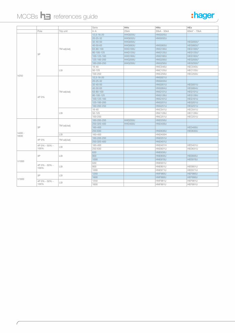
Serie HHx HNx HEx
Pole Trip unit In A 25kA 30kA - 50kA 65kA* - 70kA
h250
3P
TM adj/adj
12,5-16-20 HHG020U HNG020U
20-25-32 HHG032U HNG032U
32-40-50 HHG050U HEG050U*
40-50-63 HHG063U HNG063U HEG063U*
63-80-100 HHG100U HNG100U HEG100U*
80-100-125 HHG125U HNG125U HEG125U*
100-125-160 HHG160U HNG160U HEG160U*
125-160-200 HHG200U HNG200U HEG200U*
160-200-250 HHG250U HNG250U HEG250U*
LSI
16-40 HNC040U HEC040U
50-125 HNC125U HEC125U
100-250 HNC250U HEC250U
4P 0%
TM adj/adj
12,5-16-20 HNG021U
20-25-32 HNG033U
32-40-50 HNG051U HEG051U
40-50-63 HNG064U HEG064U
63-80-100 HNG101U HEG101U
80-100-125 HNG126U HEG126U
100-125-160 HNG161U HEG161U
125-160-200 HNG201U HEG201U
160-200-250 HNG251U HEG251U
LSI
16-40 HNC041U HEC041U
50-125 HNC126U HEC126U
100-250 HNC251U HEC251U
h400 -
h630
3PTM adj/adj
160-200-250 HHD250U HND250U
250-320-400 HHD400U HND400U
160-400 HED400U
250-630 HND630U HED630U
LSI 160-400 HND400H
4P 0% TM adj/adj160-200-250 HND251U
250-320-400 HND401U
4P 0% - 50% -
100%LSI
160-400 HND401H HED401U
250-630 HND631U HED631U
h1000
3P LSI
630 HNE630U
800 HNE800U HEE800U
1000 HNE970U HEE970U
4P 0% - 50% -
100%LSI
630 HNE631U
800 HNE801U HEE801U
1000 HNE971U HEE971U
h1600
3P LSI1250 HNF980U HEF980U
1600 HNF990U HEF990U
4P 0% - 50% -
100%LSI
1250 HNF981U HEF981U
1600 HNF991U HEF991U
MCCBs references guide

Serie x160 x250 h630 h1000 h1600
Product Version Poles In A
Trip-free switches
3 poles125 HCA125Z
160 HCA160Z
4 poles125 HCA126Z
160 HCA161Z
3 poles 250 HCB250Z
4 poles 250 HCB251Z
3 poles400 HCD400U
630 HCD630U
4 poles400 HCD401U
630 HCD631U
3 poles800 HCE800U
1000 HCE970U
4 poles800 HCE801U
1000 HCE971U
3 poles1250 HCF980U
1600 HCF990U
4 poles1250 HCF981U
1600 HCF991U
Add-on blocks
Side mounted
3 poles
125 fixed HBA127H
125 adjustable HBA125H
160 adjustable HBA160H
4 poles
125 fixed HBA128H
125 adjustable HBA126H
160 adjustable HBA161H
Bottom mounted 4 poles
160 adjustable HBB161H
250 adjustable HBB251H
400 adjustable HBD401H
500 adjustable HBD631H
Trip-free switches and add-on blocks forreferences guide
Switches and accessories forreferences guide
Switches and accessories
Products Version pole In A / Ue V x160 x250 h250 h400-h630 h1000 h1600
Auxiliaries
Shunt trip release 3/4P24V DC HXA001H HXC001H HXF001H
200-240V AC HXA004H HXC004H HXF004H
Undervoltage release 3/4P
24V DC HXA011H HXC011H HXE011H
200-240V AC HXA014H HXC014H HXE014H
380-450V AC HXA015H HXC015H HXE015H
Auxiliary contact 3/4P 1NO+1NC HXA021H HXC021H
Alarm contact 3/4P 1NO+1NC HXA024H HXC024H
Auxiliary contact - low level 3/4P 1NO+1NC HXA025H HXC025H
Alarm contact - low level 3/4P 1NO+1NC HXA026H HXC026H
Direct rotary handle HXA030H HXB030H HXC030H HXD030H HXE030H HXF030H
Extended rotary handle HXA031H HXB031H HXC031H HXD031H HXE031H HXF031H
Padlock HXA039H HXC039H HXD039H HXF039H
Motor operator 3/4P24-48V DC - HXB040H HXC040H HXD040H HXE040H HXF040H
200-240V AC - HXB042H HXC042H HXD042H HXE042H HXF042H
Connections
Extended spreader connection
3P HYA014H HYB011H HYC011H
HYD011H
(250-400A)
HYD014H
(630A)
- -
4P HYA015H HYB012H -
HYD012H
(250-400A)
HYD015H
(630A)
- -
Interphase barrier 3/4Pshort HYA019H - - - -
long HYB019H included included included included
DIN rail adaptor 3/4P HYA033H - - - - -

MCCBs, trip-free switchesx160
MCCBs
Magnetic and thermal settings
220/240V AC
IEC 60 947-2
380/415V AC
IEC 60 947-2
HDA Icu 25 kA 18 kA
Ics 25 kA 18 kA
HHA Icu 35 kA 25 kA
Ics 25 kA 20 kA
HNA Icu 85 kA 40 kA
Ics 30 kA 20 kA
HCA Icm - 2.8 kA
Icw - 2 kA - 1s
PUSH TO TRIP
TRIP
6
Thermal adjustment from 0,63 to 1 x In
¬In 15 - 50 A 63 - 80 A 100 - 125 A 160 A
Imag 600 A 1000 A 1500 A 1600 A
Magnetic adjustment fixed > 10 x In
For DIN rail mounting, use HYA033H.

MCCBs, trip-free switchesx160
Tripping curve
MCCB x160
Déclenchement à froid
Déclenchement à chaud(courant nominal)
25 A32
A63 A
100
A, 4
0 A
80 A
160
A12
5 A
, 50
A
0.01
0.1
1
10
100
1000
100101xIn (A)
Tem
ps
de
déc
lenc
hem
ent
(s)
0.001
10000
Thermal constraint curve at 400V (Let-through energy)
MCCB x160
25A
40A
63A80A
100A125A160A
I2 t (A
s)
2
101
102
103
104
101 10210,1Icc (kA)
Current limiting curve at 400V(Let-through pick current)
MCCB x160
125 A
0,8
0,5
0,3
0,25
0,7
0,9
25 A40 A63 A80 A
100 A
160 A
0.1
1
10
100
1001010,1Icc (kA)
Ip (k
A)
Hot start
(rated current)
Cold start
Trip
pin
g t
ime (s)

MCCBs, trip-free switchesx160
MCCB x160
Dimensions
11 97
68
15
45
130
25 25
25
114
111
(3 P) 75
(4 P) 100
A
(mm)
B
(mm)
C
(mm)
1P 24.8 25 111
2P 49.5 25 111
3P 74.5 25 111
4P 99.5 25 111
Terminal covers for extended straight connections
A
(mm)
B
(mm)
C
(mm)
1P 24.4 57.5 60.5
2P 49.5 57.5 60.5
3P 74.5 57.5 60.5
4P 99.5 57.5 60.5
230
(3P) 75(4P) 100
60,5
57,5
Terminal cover for extended spreader connections
A
(mm)
B
(mm)
C
(mm)
3P 106.5 50 60.5
4P 141.5 50 60.5
61
50
(3 P) 107(4 P) 142
A
A
A

MCCBs, trip-free switchesx160
min. 6 mm2 max. 70 mm2
min. 6 mm2 max. 95 mm2
6 Nm
Connection
Connection with end lugs
16maxi
55
L
Interphase barriers
L
(mm)
HYA019H 50
HYB019H 97
4
Terminals fo aluminium / copper conductors (accessory)
HYA005H, HYA006H
min. 35 mm2 max. 70 mm2
10 Nm5
Terminals fo copper conductors (standard)

MCCBs, trip-free switchesx160
Extended straight connections
35 3535
12,7
203
mm
54
17,6
Ø 8,3
122122
87
16,8 1026,8
3P
4P
35 3535
12,7
203
mm
54
17,6
Ø 8,3
122122
87
16,8 1026,8
3P
4P
17
Ø 8
6 Nm
6 Nm
Extended spreader connections
Direct rotary handle
49
127
54
45
102
(3 P) 75
(4 P) 100 121
12
112
45
102
9
200
(3 P) 75
(4 P) 100
Extended rotary handle
62 30 37
80
287m
m
12.8
140
210
58 65 58
80
287m
m
80
12.8
181

MCCBs, trip-free switchesx160
Auxiliaries
Auxiliaries for MCCBs and trip-free switches
PUSH TO TRIP
Mounting combination for auxiliaries and releases
AX
Auxiliary contact
AL
Alarm contact
SH
Shunt trip
UV
Undervoltage release
TRIP
DUVR
Delayed
undervoltage
release

Add-on blockx160
Characteristics
Reset button : Signals add-on block tripping and must be acknowledged before switching on the installation.
Test button for differential functioning : Allows to check the electrical operating of the MCCB / Add-on block association.
Mechanical test button : Allows to check the mechanical operating of the MCCB / Add-on blockassociation.
LED signaling default current level in the installation:25% (orange) and 50% (red) IΔn; green light to signal correct operating.
Remote tripping and advanced warning (50% IΔn) signaling thanks tothese contacts:
Add-on block operatingEarth leakage current (IΔn) and delay (Δt) setting
When associated with MCCB, the add-on block provides an earth faultprotection and protects against electrical shocks by direct or indirectcontacts.
The add-on blocks are protected against nuisance tripping caused bytransient voltages. Its able to detect sinusoidal alternating currents andresidual pulsating direct currents ( A type ). It also avoids miss tripping (HI type - High Immunity).
N L1 L2 L3
N L1 L2 L3
incom ing
outgoing
test button
CA
50%
electronic
O N
125A250A
V
1
V
2
63
10,30,1
0,03
I n (A)
10,5
0,30,150,06Inst.
t (s)
103
10,30,1
0,03
10,5
0,30,150,06
Inst.
I n (A)
t (s)
5
2
S (Δ
t)
A (IΔn)
0,03 0,1 0,3 1 3 6
Inst. OK OK OK OK OK OK
0.06 no OK OK OK OK OK
0.15 no OK OK OK OK OK
0.3 no OK OK OK OK OK
0.5 no OK OK OK OK OK
1 no OK OK OK OK OK

Add-on blockx160
Add-on block mounting
Dimensions
Exclusive drawer assembly system allows quick mounting and makesMCCB and add-on block association a complete monoblock unit.
Reinforced insulation connexion (class II)
System avoids the omission of terminal tightening
37
25 25
A
165
B
3P 4P
A (mm) 100 100
B (mm) 174.5 199.5
PUSH TO TRIP
4
3
6 Nm
PUSH TO TRIP
5
À Á

MCCBs, trip-free switchesx250
MCCBs
Magnetic and thermal settings
220/240V AC
IEC 60 947-2
380/415V AC
IEC 60 947-2
HHB Icu 35 kA 25 kA
Ics 25 kA 40 kA
HNB Icu 85 kA 40 kA
Ics 40 kA 20 kA
HCB Icm - 9 kA
Icw - 3 kA - 1s
Thermal adjustment from 0.63 to 1 x In
Magnetic adjustment from 6 to 13 x In (100 - 200A)
from 5 to 11 x In (250A)
58
1013l i (xIn)
6
l r (xIn)0,63
0,8
1
58
1013
%0
100%
l i (xIn)xIn / Ii
l r (xIn)0,63
0,8
1
6
6
100 - 200A 250A
Ir (x In) À 0.63 - 0.8 - 1 x In
Ii (x In) Á 6 - 8 - 10 - 13 x In 5 - 7 - 9 - 11 x In
x In/Ii Â0 - 100%
0 - 60%
 Á À

MCCBs, trip-free switchesx250
Tripping curve
MCCB x250
0.01
0.1
1
10
100
1000
100101xIn (A)
Tem
ps
de
déc
lenc
hem
ent
(s)
Déclenchement à froid
Déclenchement à chaud(courant nominal)
0.001
10000
Thermal constraint curve at 400V (Let-through energy)
MCCB x250
106
104
105
107
108
109
102 103 104 105
I2 t (x
10
A s
)6
2
100 A
250 A
Icc (kA)
Current limiting curve at 400V (Let-through pick current)
MCCB x250
0.1
1
10
100
Ip (k
A)
1001010,1Icc (kA)
0,8
0,5
0,3
0,25
0,7
0,9
Hot start
(rated current)
Cold start
Trip
pin
g t
ime (s)

MCCBs, trip-free switchesx250
Dimensions
MCCB x250
PUSH TO TRIP
96
6824
45165
35
35
35
(3 P) 105(4 P) 140
144
126
A
(mm)
B
(mm)
C
(mm)
3P 105 54.5 64
4P 140 54.5 64
PUSH TO TRIP
CA
B
Terminal covers for extended straight connections
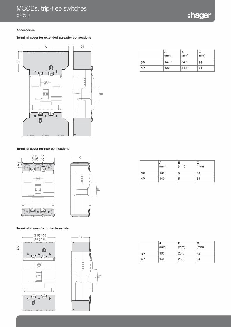
MCCBs, trip-free switchesx250
Accessories
Terminal cover for extended spreader connections
Terminal cover for rear connections
A
(mm)
B
(mm)
C
(mm)
3P 105 28.5 64
4P 140 28.5 64
Terminal covers for collar terminals
PUSH TO TRIP
C
5
(3 P) 105(4 P) 140
A
(mm)
B
(mm)
C
(mm)
3P 105 5 64
4P 140 5 64
C
55
(3 P) 105(4 P) 140
A
(mm)
B
(mm)
C
(mm)
3P 147.5 54.5 64
4P 196 54.5 64
PUSH TO TRIP
64
55
(3 P) 148(4 P) 196
A

MCCBs, trip-free switchesx250
Connection
Extended straight and spreader connections
PUSH TO TRIP
23Ø 11
PUSH TO TRIP
23
Rear connections
5
12 Nm6
5
12 Nm6
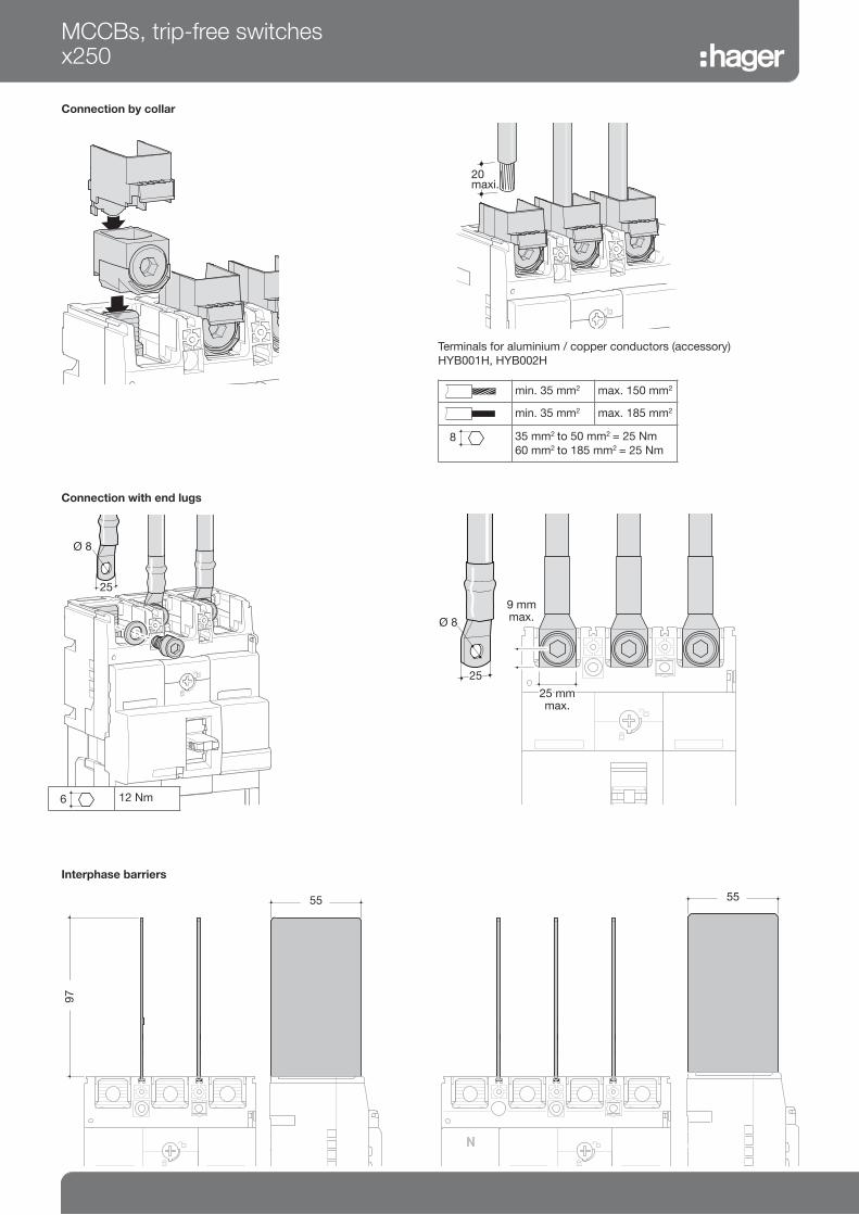
20 maxi.
MCCBs, trip-free switchesx250
Connection with end lugs
Ø 8
25
25 mmMax.
25 mmmax.
9 mmmax.Ø 8
25
min. 35 mm2 max. 150 mm2
min. 35 mm2 max. 185 mm2
5
35 mm2 to 50 mm2 = 25 Nm
60 mm2 to 185 mm2 = 25 Nm
Connection by collar
8
Interphase barriers
97
55
55
5
12 Nm6
Terminals for aluminium / copper conductors (accessory)
HYB001H, HYB002H

MCCBs, trip-free switchesx250
Accessories
Rotary handle
PUSH TO TRIPPUSH TO TRIP
12
108
45 102
9
200
(3 P) 105(4 P) 140
Motor operator
180 178
310
331,5
Extended rotary handle
PUSH TO TRIPPUSH TO TRIP
48,5
53,745
101,
8
A 116
90
155
165
90
HXB040H HXB042H
Operating voltage 24V DC 230-240V AC
Operating current / startingcurrent peak value (A)
24V DC 18/26 -
230-240V AC - 3.5/7
Operating time (s)
(ON) 0.1s
(OFF) 0.1s
(RESET) 0.1s
Power supply required 300VA min.
Dielectric properties (1 min) 1000V AC 1500V AC
(3P/4P) 105
(3P/4P) 105

DUVR
Delayed
undervoltage
release
MCCBs, trip-free switchesx250
Auxiliaries
Auxiliaries for MCCBs and trip-free switches
Mounting combination for auxiliaries and releases
AX
Auxiliary contact
AL
Alarm contact
SH
Shunt trip
UV
Undervoltage release

Add-on blocksx250
Add-on block operatingEarth leakage current (IΔn) and delay (Δt) setting
63
10,30,1
0,03
I n (A)
10,5
0,30,150,06Inst.
t (s)
103
10,30,1
0,03
10,5
0,30,150,06
Inst.
I n (A)
t (s)
5
2
N L1 L2 L3
N L1 L2 L3
incom ing
outgoing
test button
CA
50%
electronic
O N
125A250A
V
1
V
2
Characteristics
Reset button : Signals add-on block tripping and must be acknowledged before switching on the installation.
Test button for differential operating : Allows to check the electrical operating of the MCCB / Add-on block association.
Mechanical test button : Allows to check the mechanical operating of the MCCB / Add-on blockassociation.
LED signaling default current level in the installation:25% (orange) and 50% (red) IΔn; green light to signal correct operating.
Remote tripping and advanced warning (50% IΔn) signaling thanks tothese contacts:
When associated with MCCB, the add-on block provides an earth faultprotection and protects against electrical shocks by direct or indirectcontacts.
The add-on blocks are protected against nuisance tripping caused bytransient voltages. Its able to detect sinusoidal alternating currents andresidual pulsating direct currents ( A type ). It also avoids miss tripping (HI type - High Immunity).
S (Δ
t)
A (IΔn)
0.03 0.1 0.3 1 3 6
Inst. OK OK OK OK OK OK
0.06 no OK OK OK OK OK
0.15 no OK OK OK OK OK
0.3 no OK OK OK OK OK
0.5 no OK OK OK OK OK
1 no OK OK OK OK OK
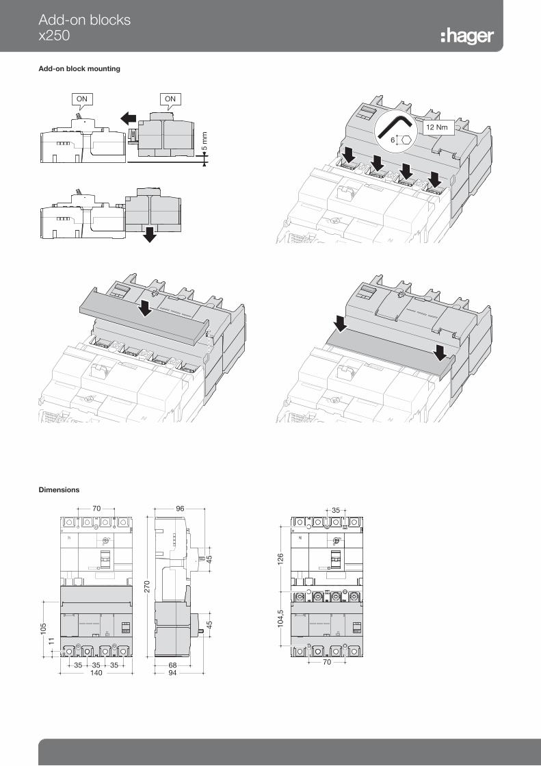
Add-on blocksx250
Add-on block mounting
Dimensions
68
45
105
35 35 3594
11
140
270
45
9670
70
104,
512
6
35
12 Nm
ON ON

MCCBs
Magnetic and thermal settings
10
6 8
1
0,630,8
Ir (x In) Ii (x In)
220/240 V
AC
(kA)
380/415 V
AC
(kA)
660/690 V
AC
(kA)
HHGIcu 35 25 -
Ics 27 19 -
HNGIcu 35 50 -
Ics 65 25 -
HEGIcu 85 65 -
Ics 85 36 -
HNCIcu 85 50 7.5
Icu 85 25 7.5
HECIcu 100 70 20
Icu 100 70 15
MCCBs h250
Thermal adjustment from 0.63 to 1 x In
Magnetic adjustment from 6 to 10 x In (250A)
from 6 to 13 x In (160 and 200A)
from 6 to 12 x In (32, 63, 100 and 125A)
Characteristics (*) Use
Electronic trip unit setting (LSI)
0,4
0,5
0,8
0,63 1
0,950,9
1
2
4
3
6
7
5
CharacteristicsIr (A)
PICK UP
1 2
xInIR (A)
8
9
L - Long delay - protection against overloads: Ir and tr settings
S - Short delay - protection against short circuits: Isd and tsd
settings
I - Instantaneous - max. instantaneous threshold (< 10 ms) in case of
short circuit: 2,5 to 10 x Ir.
3 P 4 P
pos. 1
pos. 2 and 3
pos. 4 and 5
pos. 1, 4 and 7
pos. 2, 5 and 8
pos. 3, 6 and 9
Generator protection
Standard protection
Motor protection
LSI
In A
3P 4P
Long Time Delay Short Time Delay Inst Long Time Delay Short Time Delay Inst Protection
Ir (x In) tr (s) isd (xlr) tsd (s) li (xlr) Ir (x In) tr (s) isd (xlr) tsd (s) li (xlr) Neutral
Ir (x In)
0.4 OK OK
0.5 OK OK
0.63 OK OK
0.8 OK OK
0.9 OK OK
0.95 OK OK
1 OK OK
Characteristics
1 11s at 2 xlr 2.5 0.1 14
(max
12 x In)
11 s at 2 xlr 2.5 0.1 14
(max
10 x In)
no
2 21s at 2 xlr 21 s at 2 xlr 5
3 5 7.5 s at 6 xlr 10 0.2
4 5 s at 6 xlr 10 11 s at 2 xlr 2.5 0.1 50%
5 7.5 s at 6 xlr 0,2 21 s at 2 xlr 10
6 7.5 s at 6 xlr 2.5 0.2
7 11 s at 6 xIr 2.5 0.1 100%
8 21 s at 2 xIr 5
9 21 s at 2 xIr 10 0.2
1
2
T
x Ir I
Ir ajustable

Tripping curve
MCCB h250 TM
MCCBs h250

MCCB h250 3P LSI
0.01
0.1
1
10
100
1000
10000
Tem
ps d
e dé
clen
chem
ent (
s)
100001000100%Ir
5
4
5
32
1
1, 2, 3, 4
LTD pick-up current
Characteristics
Standard
No. 1
LTD Tr (s) 11
STD Isd
tsd
li
x Ir
(s)
x Ir
200 % x Ir 600 % x Ir
INST
0.1
14 (max 13 x In)
2.5
2
21
0.1
2.5
3
21
0.1
5
4
5
0.1
10
5
7.5
0.2
10
Ir x In 10.950.90.80.630.50.4
MCCBs h250Trip
pin
g t
ime (s)

MCCBs h250
MCCB h250 4P LSI
0.01
0.1
1
10
100
1000
10000
Tem
ps d
e dé
clen
chem
ent (
s)
100001000100
1, 4, 7
2, 5, 83, 6, 9
%Ir
LTD pick-up current
Characteristics No. 987654321
Tr (s) 7.5 s
600% x Ir
21 s11 s7.5 s21 s11 s7.5 s21 s11 sLTD
Isd x Ir
(s)
x Ir
200 % x Ir600% x Ir200 % x Ir600% x Ir200 % x Ir
0.2
STD
INST
Neutral protection
0.10.20.10.20.1
14 (max 13 x In)
no 0.5 1
1052.51052.51052.5
Ir x In 10.950.90.80.630.50.4
Trip
pin
g t
ime (s)

Thermal constraint curve at 400V (Let-through energy)
MCCB h250
102 103 104 105
106
104
105
107
108
109
I2 t (A
s)
2
Icc (kA)
Current limiting curve at 400V (Let-through peak current)
MCCB h250
0.1
1
10
100
Ip (k
A)
1001010,1Icc (kA)
0,8
0,5
0,3
0,25
0,7
0,9
MCCBs h250
HNC... upto 50kAHEC... upto 70kA
HNC... upto 50kAHEC... upto 70kA

Dimensions
MCCBs
A
(mm)
3P 105
4P 140
MCCBs h250
A
(mm)
3P 105
4P 140
Accessories
Terminal covers for extended straight connections
Terminal cover for rear connections (LSI only)
A
(mm)
3P 105
4P 140
PUSH TO TRIP
A
35 35
165
144
55
89A
275
8 96
170
(3P) 105(4P) 140
89 (LSI)52 (TM)
A
103 (LSI)68 (TM)
45 102
126 (LSI)91 (TM)

MCCBs h250
Connection
Extended straight and spreader connections
2323
29,5
Ø 1
1
P
120
48,5 48,5
Connection with end lugs
Ø 8
25
Connection by collar
20max.
19 Nm
1 2
min. 35 mm2 max. 120 mm2
min. 35 mm2 max. 120 mm2
5
19 Nm
5
12.7 Nm6
5
12.7 Nm6
6
22
Terminals for copper conductors
HYC003H, HYC004H

MCCBs h250
Rear connections (LSI only)
612 Nm
Accessories
Direct rotary handle
15 56
10
10 91
11.8 Nm
72
193 (LSI)
158 (TM)

Extended rotary handle
155
204,589,5
Motor operator
MCCBs h250
171 (LSI)
136 (TM)
21,5
358
19,5x
44
12
590
205 (LSI)170 (TM)
HXC040H HXC042H
Operating voltage 24V DC 230-240V AC
Operating current / startingcurrent peak value (A)
24V DC 18/26 -
230-240V AC - 3.5/7
Operating time (s)
(ON) 0.1s
(OFF) 0.1s
(RESET) 0.1s
Power supply required 300VA min.
Dielectric properties (1 min) 1000V AC 1500V AC
90
120
(3 P) 105
(4 P) 140
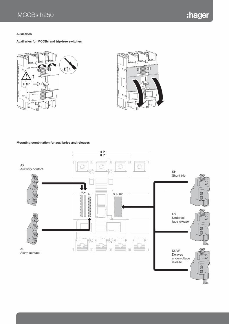
Auxiliaries
Auxiliaries for MCCBs and trip-free switches
TRIP
6
21
AX
Auxiliary contact
AL
Alarm contact
SH
Shunt trip
UV
Undervol-
tage release
MCCBs h250
DUVR
Delayed
undervoltage
release
Mounting combination for auxiliaries and releases

MCCBs
Settings
Magnetic and thermal settings
TM 400 A
126
8 10
10,63
0,8
Ir (x In) Ii (x In)
B
A
220/240 V
AC
(kA)
380/415 V
AC
(kA)
660/690 V
AC
(kA)
h400/h630
HND
Icu 85 50 20
Ics 85 50 15
h630
HED
Icu 100 70 20
Ics 85 50 15
h630
HCD
Icm _ 9 _
Icw _ 5 kA-0.3 s _
MCCBs, trip-free switchesh400 - h630
Thermal adjustment from 0.63 to 1 x In
Magnetic adjustment from 6 to 12 x In

LSI
In A
250 A / 400 A 630 A
Long Time
Delay
Short Time
Delay
Inst Long Time
Delay
Short Time
Delay
Inst
Ir (x In) tr (s) isd (xlr) tsd (s) li (xlr) Ir (x In) tr (s) isd (xlr) tsd (s) li (xlr)
➂
ÀIr (x In)
0.4 OK OK
0.5 OK OK
0.63 OK OK
0.8 OK OK
0.85 _ OK
0.9 OK OK
0.95 OK OK
1 OK OK
➂
ÁCharacteristics
1 11s at 2 xlr 2.5 0.1 14
(max
13 x
In)
11s at 2 xlr 2.5 0.1 14
(max
10 x
In)
2 21s at 2 xlr 21s at 2 xlr
3 5 5
4 5 s at 6 xlr 10 5 s at 6 xlr 8
5 10 s at 6 xlr 0.2 10 s at 6 xlr 0.2
6 19 s at 6 xlr 16 s at 6 xlr
7 29 s at 6 xlr _ _ _
Â➂Neutral
protection
0%
50%
100%
4
2.5 5 10 14
0.1S
0.2S
5,6,7
7
6
5
31,2
4
3
1
2
T
x Ir I
Ir ajustable
Electronic trip unit setting (LSI)
LSI250/400/630 A 1 B2
3
1
0,4
0,5
0,8
0,63 0,95
0,90,85
1
2
4
3
6
7
5
CharacteristicsIr (A)
TEST INPICK UP
ON 1xIR
OFF 0,5xIR
NP
Neutral settings:
À Long delay current Ir setting
Á Other curve characteristics setting (tr, Isd, tsd)
 Neutral protection against overloads setting
MCCBs, trip-free switchesh400 - h630
L - Long delay - protection against overloads: Ir and tr
settings
S - Short delay - protection against short circuits: Isd
and tsd settings
I - Instantaneous - max. instantaneous threshold (< 10
ms) in case of short circuit: 2.5 to 10 x Ir (250 - 400A)
and 2.5 to 8 x Ir (630A).
(*) Characteristic 1 : use for generators protection.
Characteristic 2 to 4 - standard protection : options allow coordination optimisation with other products.
Characteristic 5 to 7 - motor protection: use positions according to motor starting characteristics.
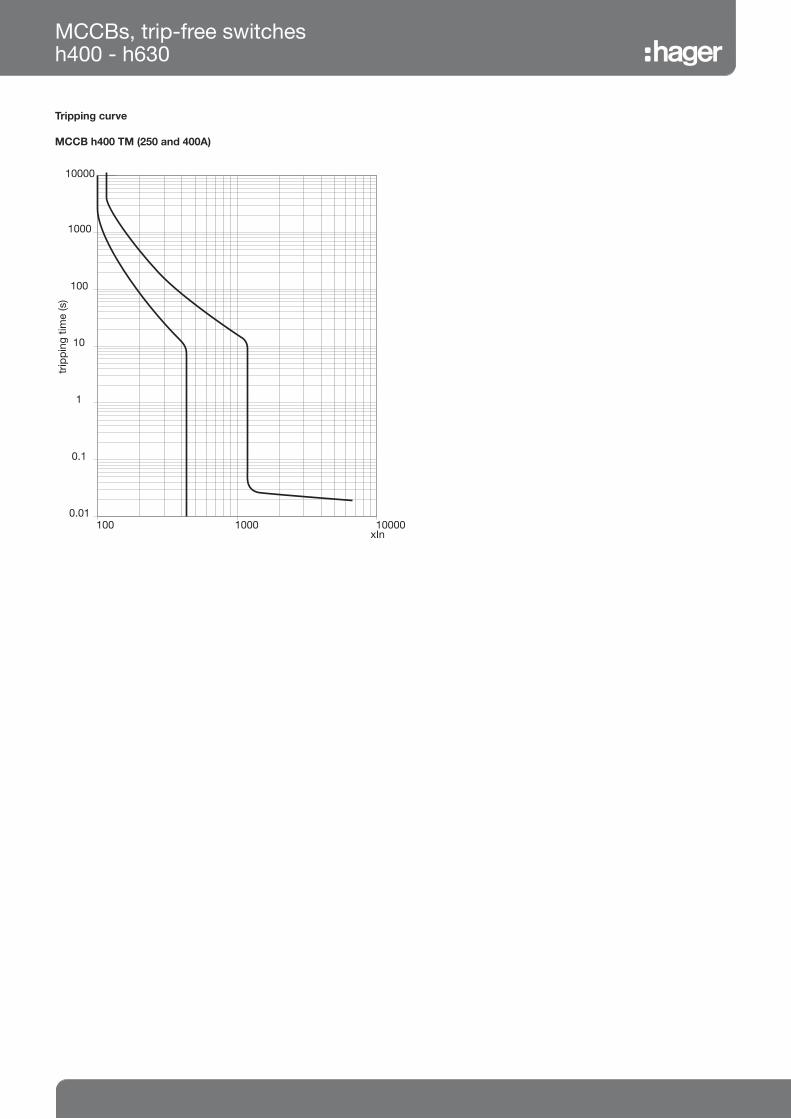
Tripping curve
MCCB h400 TM (250 and 400A)
MCCBs, trip-free switchesh400 - h630
0.01
0.1
1
10
100
1000
10000
100001000100xIn
trip
ping
tim
e (s
)

0.01
0.1
1
10
100
1000
10000
Tem
ps d
e dé
clen
chem
ent (
s)
100001000100%Ir
3
1, 2, 3, 4
5, 6
1 24
5 67
Electronic trip unit setting (LSI)
MCCB h630 LSI (250A and 400A)
IR (A)
LTD Pick-up current IR xIn 0.4 0.5 0.63 0.8 0.9 0.95 1
Characteristics No. 1 2 3 4 5 6 7
Standard LTD tR (s) 11 21 21 5 10 19 29
200% x I R 600% x I R
STD Isd xIR 2.5 5 10
tsd (s) 0.1 0.2
INST Ii xIR 14 (max : 13 x In)
Optional N IN xIn 0 - 0.5 - 1
tN (s) tN=tR
MCCBs, trip-free switchesh400 - h630
Trip
pin
g t
ime (s)
Tripping curve
MCCB h630 LSI (250A and 400A)

Electronic trip unit setting (LSI)
MCCB h630 LSI (630A electronic)
IR (A)
LTD Pick-up current IR xIn 0.4 0.5 0.63 0.8 0.85 0.9 0.95 1
Characteristics No. 1 2 3 4 5 6
Standard LTD tR (s) 11 21 21 5 10 16
200% x I R 600% x I R
STD Isd xIR 2.5 5 8
tsd (s) 0,1 0.2
INST Ii xIR 14 (max : 13 x In)
Optional N IN xIn 0 - 0.5 - 1
tN (s) tN=tR
0.01
0.1
1
10
100
1000
10000
Tem
ps
de
déc
lenc
hem
ent
(s)
100001000100
3
1, 2, 3, 4
5, 6
1 24 5
6
%Ir
MCCBs, trip-free switchesh400 - h630
Trip
pin
g t
ime (s)
Tripping curve
MCCB h630 LSI (630A electronic)

MCCBs, trip-free switchesh400 - h630
Thermal constraint curve at 400V (Let-through energy)
MCCB h400 TM (250A and 400A)
I2 t (x
A s
)2
107
106
105
104
103
108
104103102101 105
HHD... upto 25kAHND... upto 50kA
MCCB h630 LSI (250A and 400A)
I2 t (A
s)
2
0,1
1
101
102
101 10210,1 Icc (kA)
I2 t (x
10
A s
)6
2
0,1
1
101
102
101 10210,1Icc (kA)
MCCB h630 LSI (630A)
HND... upto 50kAHED... upto 70kA
HND... upto 50kAHED... upto 70kA
(kA)

Current limiting curve at 400V (Let-through peak current)
MCCB h630 LSI (250A and 400A)
MCCB h400 TM
0.1
1
10
100
Ip (k
A)
1001010,1Icc (kA)
0,8
0,5
0,3
0,25
0,7
0,9
0.1
1
10
100
Ip (k
A)
1001010,1Icc (kA)
0,8
0,5
0,3
0,25
0,7
0,9
MCCB h630 LSI (630A)
HHD... upto 25kAHND... upto 50kAHED... upto 70kA
HND... upto 50kAHED... upto 70kA
MCCBs, trip-free switchesh400 - h630
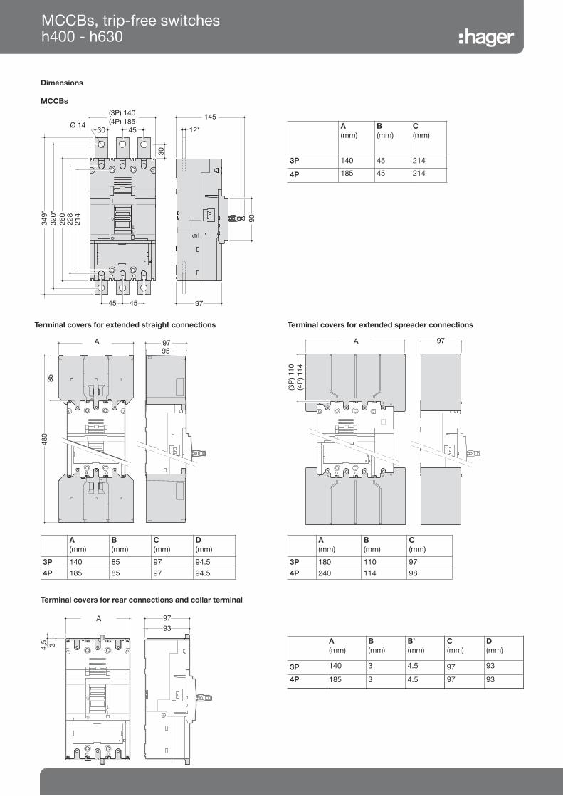
Dimensions
MCCBs
30
45Ø 14
30 12*
145
97
90260
320*
349*
45 45
228
(3P) 140(4P) 185
214
A
(mm)
B
(mm)
C
(mm)
3P 140 45 214
4P 185 45 214
MCCBs, trip-free switchesh400 - h630
Terminal covers for extended straight connections
8548
0
9795
(3P) 140(4P) 185
A
(mm)
B
(mm)
C
(mm)
D
(mm)
3P 140 85 97 94.5
4P 185 85 97 94.5
Terminal covers for extended spreader connections
97(3P) 180(4P) 240
(3P
) 110
(4P
) 114
A
(mm)
B
(mm)
C
(mm)
3P 180 110 97
4P 240 114 98
Terminal covers for rear connections and collar terminal
97
4,5 3
93
(3P) 140(4P) 185
A
(mm)
B
(mm)
B’
(mm)
C
(mm)
D
(mm)
3P 140 3 4.5 97 93
4P 185 3 4.5 97 93
A A
A

MCCBs, trip-free switchesh400 - h630
Connection
Connection for aluminium / copper conductors
(h400 TM, h630 LSI)
25 maxi.
Extended straight and spreader connections
3P
60
349
Ø14
148
4P
30
30
60 60
60 60
208
4P
163
30
30 45 Ø 14
30
Rear connections
4545 45
228
1515
3P
4P 55 (250-400A)
45 (630A)
15
115 (250-400 A)95 (630 A)
5
22.5 Nm8
max. 1x240 mm2
5
25 Nm10
HYD005 (3P) - HYD006H (4P)
HYD007 (3P) - HYD008H (4P)
max. 2x240 mm2
5
25 Nm10
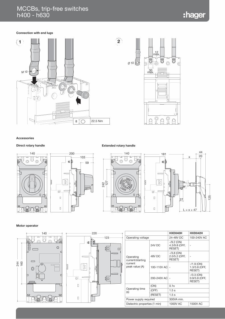
MCCBs, trip-free switchesh400 - h630
Connection with end lugs
M 10 30max.
12max.
Ø 10
1 2
5
22.5 Nm8
Accessories
Direct rotary handle
139 200103
59
242
139
127
181
L = x + 47
27
20x
44
125
Extended rotary handle
244
139,5
160
Motor operator
HXD040H HXD042H
Operating voltage 24-48V DC 100-240V AC
Operating current/startingcurrent peak value (A)
24V DC-/9.2 (ON)4.3/9.8 (OFF,RESET)
-
48V DC-/3,8 (ON)2.0/5.2 (OFF,RESET)
-
100-110V AC --/1.9 (ON)1.3/3.8 (OFF,RESET)
200-240V AC --/3.3 (ON)0.9/3.8 (OFF,RESET)
Operating time (s)
(ON) 0.1s
(OFF) 1.5 s
(RESET) 1.5 s
Power supply required 300VA min.
Dielectric properties (1 min) 1000V AC 1500V AC
220
123
140 140
140

Auxiliaries
Auxiliaries for MCCBs and free tripping switches
6
TRIP
6
AX
Auxiliary contact
AL
Alarm contact
SH
Shunt trip
UV
Undervol-
tage release
MCCBs, trip-free switchesh400 - h630
DUVR
Delayed
undervoltage
release
Mounting combination for auxiliaries and releases

Add-on block h630
63
10,30,1
0,03
I n (A)
10,5
0,30,150,06Inst.
t (s)
103
10,30,1
0,03
10,5
0,30,150,06
Inst.
I n (A)
t (s)
5
2
N L1 L2 L3
N L1 L2 L3
incom ing
outgoing
test button
CA
50%
electronic
O N
125A250A
V
1
V
2
Characteristics
Reset button : Signals add-on block tripping and must be acknowledged before switching on the installation.
Test button for differential functioning : Allows to check the electrical operating of the MCCB / Add-on block association.
Mechanical test button : Allows to check the mechanical operating of the MCCB / Add-on blockassociation.
LED signaling default current level in the installation:25% (orange) and 50% (red) IΔn; green light to signal correct operating.
Remote tripping and advanced warning (50% IΔn) signaling thanks tothese contacts:
Add-on block operatingEarth leakage current (IΔn) and delay (Δt) setting
When associated with MCCB, the add-on block provides an earth faultprotection and protects against electrical shocks by direct or indirectcontacts.
The add-on blocks are protected against nuisance tripping caused bytransient voltages. Its able to detect sinusoidal alternating currents andresidual pulsating direct currents ( A type ). It also avoids miss tripping (HI type - High Immunity).
S (Δ
t)
A (IΔn)
0.03 0.1 0.3 1 3 6
Inst. OK OK OK OK OK OK
0.06 no OK OK OK OK OK
0.15 no OK OK OK OK OK
0.3 no OK OK OK OK OK
0.5 no OK OK OK OK OK
1 no OK OK OK OK OK

Add-on block h630
Add-on block mounting
Dimensions
97
45
45 45 45121
16
185
119
22.5 Nm
À
Á Â
Association / Compatibility
250 - 400A 630A x 0.8
HBD401H
400A
HBD631H
500A
(Ie: 630A x 0.8)

Tripping curve
MCCB h1000 LSI (630-800A)
Electronic trip unit setting (LSI)
MCCBs 630-800A electronic
MCCBs, trip-free switchesh1000
IR (A)
LTD Pick-up current IR xIn 0.4 0.5 0.63 0.8 0.9 0.95 1
Characteristics No. 1 2 3 4 5 6 7
Standard LTD tR (s) 11 21 21 5 10 19 29
200% x I R 600% x I R
STD Isd xIR 2.5 5 10
tsd (s) 0.1 0.2
INST Ii xIR 14 (max : 12 x In)
Optional NP IN xIR 0.5 or 1 or NON (IN x 105% NT, IN x 120% T)
tN (s) IN=tR

Tripping curve
MCCB h1000 LSI (1000A)
Electronic trip unit setting (LSI)
MCCBs 1000A electronic
MCCBs, trip-free switchesh1000
IR (A)
LTD Pick-up current IR xIn 0.4 0.5 0.63 0.8 0.9 0.95 1
Characteristics No. 1 2 3 4 5 6
Standard LTD tR (s) 11 21 21 5 10 16
200% x I R 600% x I R
STD Isd xIR 2.5 5 8
tsd (s) 0.1 0.2
INST Ii xIR 14 (max : 10 x In)
Optional NP IN xIn 0.8
tN (s) IN=tR

Thermal constraint curve at 400V (Let-through energy)
MCCB h1000
Current limiting curve at 400V (Let-through peak current)
MCCB h1000
HNE…up to 50kAHEE…up to 70kA
MCCBs, trip-free switchesh1000

Dimensions
MCCBs
145
99,535 10
90433
40 70
273
403
331
B
A
243
MCCBs, trip-free switchesh1000
Terminal covers for extended straight connections
A
(mm)
B
(mm)
3P 210 180
4P 280 250
100
534
130
(3 P) 215 (4 P) 285
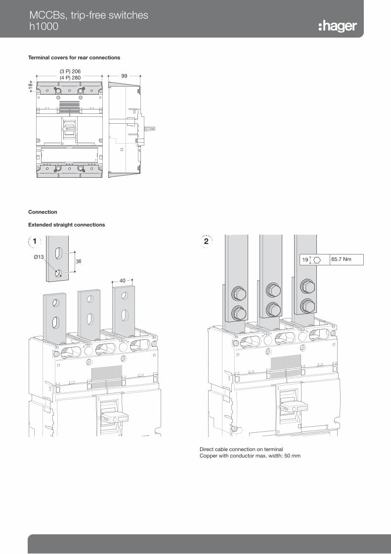
Connection
Extended straight connections
50
36 Ø13
1
Direct cable connection on terminal
Copper with conductor max. width: 50 mm
2
MCCBs, trip-free switchesh1000
99
18
(3 P) 206(4 P) 280
Terminal covers for rear connections
5
65.7 Nm19
40
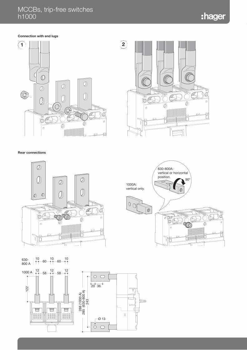
MCCBs, trip-free switchesh1000
Connection with end lugs
1 2
Rear connections
90°
58
122
121258
12
243
288
(100
0 A
)28
5 (6
30-8
00 A
)
20 36
Ø 13
601010
6010
1000 A
630-800 A
1000A:
vertical only.
630-800A:
vertical or horizontal
position.

120
127
115
120
127
Accessories
Direct rotary handle
115140
160
Motor operator
MCCBs, trip-free switchesh1000
213
113,5
200
103
59
125
181
L = x+47
20
45
HXE040H HXE042H
Operating voltage 24-48V DC 100-240V AC
Operating current/startingcurrent peak value (A)
24V DC-/12 (ON)6/11.5 (OFF,RESET)
-
48V DC-/7 (ON)3.2/6.5 (OFF,RESET)
-
100-110V AC --/2.2 (ON)1.7/3.5 (OFF,RESET)
200-240V AC --/2.2 (ON)1.3/3.5 (OFF,RESET)
Operating time (s)
(ON) 0.1s
(OFF) 1.5 s
(RESET) 1.5 s
Power supply required 300VA min.
Dielectric properties (1 min) 1000V AC 1500V AC
Extended rotary handle
Connection for aluminium / copper conductors (h1000)
max. 4x240 mm2
5
25 Nm
HYE007 (3P) - HYE008H (4P)
10
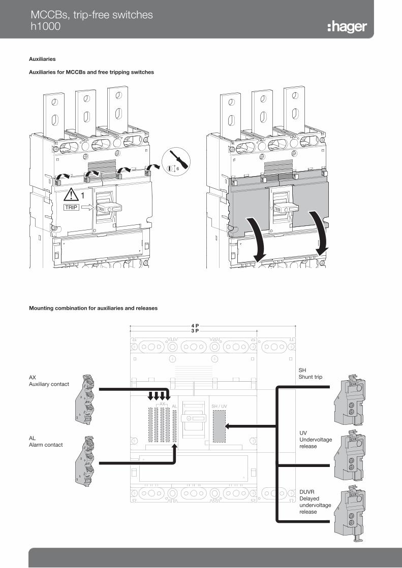
Auxiliaries
Auxiliaries for MCCBs and free tripping switches
TRIP
6
1
2
Mounting combination for auxiliaries and releases
AL SH / UVAX
HXC 024 HHXC 026 H
L
X
HXC 021 HHXC 025 H
SH
UV
DUVR
3 P4 P
AX
Auxiliary contact
AL
Alarm contact
SH
Shunt trip
UV
Undervoltage
release
MCCBs, trip-free switchesh1000
DUVR
Delayed
undervoltage
release

MCCBs
Electronic trip unit settings (LSI)
7
0,4
0,5
0,8
0,63 1
0,950,9
1
2
4
3
65
CharacteristicsIr (A)
TEST INPICK UPOFF
ON
220/240 V
AC
(kA)
380/415 V
AC
(kA)
660/690 V
AC
(kA)
HNFIcu 100 50 25
Ics 75 50 25
HEFIcu 100 70 45
Ics 75 50 34
HCFIcm 45 kA
Icw 20 kA-0.3 s
MCCBs, trip-free switchesh1600
L - Long delay - protection against overloads: Ir and tr settings
S - Short delay - protection against short circuits: Isd and tsd settings
I - Instantaneous - max. instantaneous threshold (< 10 ms) in case of short
circuit: 2,5 to 10 x Ir.
¿
Ir(A)
¡
Im
¬
N
LSI 0.4 - 1
In
2.5 -
10 Ir
0%
50%
100 %
¿ ¡
¬
LSI
In A
1250 - 1600 A
Long Time
Delay
Short Time Delay Inst
Ir (x In) tr (s) isd (xlr) tsd (s) li (xlr)
➂
À
Ir (x In)
0.4 OK
0.5 OK
0.63 OK
0.8 OK
0.9 OK
0.95 OK
1 OK
➂
Á
Characteristics*
1 11s at 2 xlr 2.5 0.1 14 (max 12 x
In)2 21s at 2 xlr
3 5
4 5 s at 6 xlr 10
5 10 s at 6 xlr 0.2
6 19 s at 6 xlr
7 29 s at 6 xlr
Â
Neutral
protection
0%
50%
100%
(*) Characteristic 1 : use for generators protection.
Characteristic 2 to 4 - standard protection : options allow coordination optimisation with other products.
Characteristic 5 to 7 - motor protection: use positions according to motor starting characteristics.

Tripping curve
MCCB h1600 LSI
Electronic trip unit setting (LSI)
MCCBs 1250A and 1600A electronic
MCCBs, trip-free switchesh1600
IR (A)
LTD Pick-up current IR xIn 0.4 0.5 0.63 0.8 0.9 0.95 1
Characteristics No. 1 2 3 4 5 6 7
Standard LTD tR (s) 11 21 21 5 10 19 29
200% x I R 600% x I R
STD Isd xIR 2.5 5 10
tsd (s) 0.1 0.2
INST Ii xIR 14 (max : 12 x In)
Optional NP IN xIR 0,5 or 1 or NON (IN x 105% NT, IN x 120% T)
tN (s) IN=tR

Thermal constraint curve at 400V (Let-through energy)
MCCB h1600
I2 t (A
s)
2
109
1010
104 105
108
107
103102Icc (kA)
Current limiting curve at 400V (Let-through peak current)
MCCB h1600
3φ
1000
100
10
1
0.1
MMaaxx
.. LLee tt
--tthhrr
oouugg hh
ppee aa
kk ccuu
rrrree nn
tt ((kk
AA))
001011 1000
PPrroossppeeccttiivvee sshhoorrtt--cciirrccuuiitt ccuurrrreenntt iinn RRMMSS ssyymm.. ((kkAA))
HNE…up to 50kAHEE…up to 70kA
MCCBs, trip-free switchesh1600
HNF... upto 50kAHEF... upto 70kA

Dimensions
MCCBs
191
140
95570
44,5 46 2070
370
541
476
338
11
BA
MCCBs, trip-free switchesh1600
A
(mm)
B
(mm)
3P 210 185
4P 280 255
Connection
Connection with end lugs
65 Nm
1 2
5
65.7 Nm19

Accessories
Direct rotary handle Extended rotary handle
257 45
125
115140
322
20
165
210
173,
5
Motor operator
MCCBs, trip-free switchesh1600
260,5
130
HXF040H HXF042H
Operating voltage 24V DC 200-230V AC
Operating current / startingcurrent peak value (A)
24V DC-/4.5 (ON)4.0/12.0 (OFF,RESET)
-
200-230V AC --/1.2 (ON)1.0/3.2 (OFF,RESET)
Operating time (s)
(ON) 0,06s
(OFF) 3s
(RESET) 3s
Power supply required 300VA min.
Dielectric properties (1 min) 500V AC 1500V AC

Auxiliaries
Auxiliaries for MCCBs and free tripping switches
TRIP
1
Mounting combination for auxiliaries and releases
AX
Auxiliary contact
AL
Alarm contact
SH
Shunt trip
UV
Undervol-
tage release
MCCBs, trip-free switchesh1600
DUVR
Delayed
undervoltage
release