mcdonald's hc932-934 manual - parts...
TRANSCRIPT
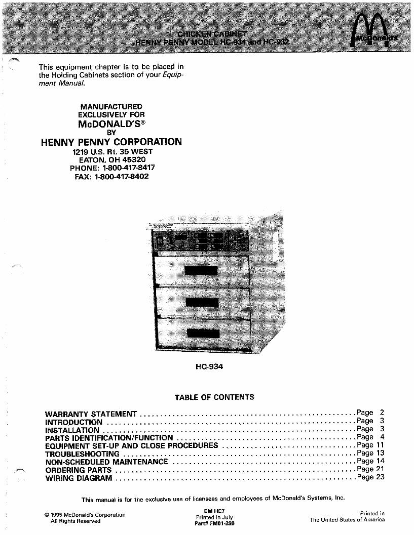
This equipment chapter is to be placed in the Holding Cabinets section of your Equip- men t Manual.
MANUFACTURE EXCLUS IVlcDO
ENNY ~~NN~~~~~~*~,~ 1219 U.S. Rt. 35 WEST
EATON, OH 45320 PHONE: I-800-417-8417
FAX: I-800-417-8402
TA
ARRANTY STATEME T.....................................................Page 2 . . . . . . ..*..*...*............................*...............* Page 3
'C'P;iidl;riFbiu'di'id6+i6 . . . Page 3
‘:::::::::::::::::::::::::::::::::::::::::...Page 4 EQUIPMENT SET-UP AND CLOSE PROCED RES . . . . . . . . . . . . . . . . . . . . . . . . . . . . . . . ..Page 11 TROUBLESHOOTING . . . . . . , . . . . . . . . . . . . . . . . . . . . . . . . . . . . . . . . . . . . . . . . . . . . . . . . . , Page 13 NON-SCHEDULED MAINTENANCE . . . . . . . . . . . . . . . . . . . . . . . . . . . . e . . . . . . . . . . . . . . . . Page 14
RINGPARTS . . . . . . . . . . . . . . . . . . . . . . . . . . . . . . . . . . . . . . . . . . . . . . . . . . . . . . . . . ..Page21 . . . . . . . . . . . . . . . . . . . . . . . . . . . . . . . . . . . . . . . . . . . . . . . . . . . . . . . . . ..Page23
This manual is for the exclusive use of licensees and employees of McDonald’s Systems, Inc.
0 1995 McDonald’s Corporation All Rights Reserved
EM HC7 Printed in July
Pati# FMOI-298
Printed in The United States of America

enny Penny Corporation makes the following limited warranties to the original purchaser only for Kenny Penny appliances and replacement parts:
New Equipment -Any part of a new appliance, except lamps and fuses, which proves to be defective in the material or workmanship within 1 year from date of original installation, will be repaired or replaced without charge F.O.B. factory, Eaton, Ohio, or F.O.B. authorized dis- tributor. To validate this warranty, the registra- tion card for the appliance must be mailed to Henny Penny within 10 days after installation.
Replacement Parts - Any appliance replace- ment part, except lamps and fuses, which proves to be defective in material or workman- ship within 90 days from date of orginal instal- lation will be repaired or replaced without charge F.O.B. factory, Eaton, Ohio, or F.O.B. authorized distributor.
This warranty covers only the repair or replace- ment of the defective part and does not include any labor charges for the removal and installa- tion of any parts, travel or other expenses incidental to the repair or replacement of a part.
THE ABOVE LIMITED WARRANTY SETS FORTH THE SOLE REMEDY AGAINST HENNY PENNY FOR ANY BREACH OF WARRANTY OR OTHER TERM. BUYER AGREES THAT NO OTHER REMEDY (INCLUDING CLAIMS FOR ANY INCIDENTAL OR CONSEQUENTIAL DAMAGES) SHALL BE AVAILABLE.
The above limited warranty does not apply (a) to damage resulting from accident, alteration, misuse, or abuse; (b) if the equipment’s serial number is removed or defaced; or (c) for lamps and fuses. THE ABOVE LIMITED WARRANTY IS EXPRESSLY IN LIEU OF ALL OTHER WAR- RANTIES, EXPRESS OR IMPLIED, INCLUDING MERCHANTABILITY AND FITNESS, AND ALL OTHER WARRANTIES ARE EXCLUDED. HENNY PENNY NEITHER ASSUMES NOR AUTHORIZES ANY PERSON TO ASSUME FOR IT ANY OTHER OBLIGATION OR LIABILITY.
Should outside assistance be required, call your local independent Henny Penny distributor. If additional help is required, contact Henny Penny Corporation direct in Eaton, Ohio.
Any claim must be presented to either Henny Penny or the distributor from whom the appli- ance was purchased. No allowance will be granted for repairs made by anyone else without Henny Penny’s written consent. If damage occurs during shipping, notify the carrier at once so that a claim may be filed.
2
~.,s?=-.,
,--
I CT
The staging cabinet is a 3 drawer, dry-air heat- ed cabinet. The cabinet is used to stage cooked product for a time period of 30 minutes, or 60 minutes.
Features:
Heat is uniformly circulated throughout the cabinet.
Removable drawers, baskets and crumb trays for easy cleaning.
Front panel temperature calibration.
4 or 6 independent programmable timers.
a. Set time from 1 to 99 minutes.
b. Capability to change timer during timing cycle.
c. Continuous timing through power inter- ruptions
Self-diagnostic program for temperature probe and hi-limit failures.
Ability to lock preset times and setpoint temperature.
Easy front panel programming for times and temperatures.
UL and NSF listed.
This piece of equipment is made in America and has American sizes on hardware. All metric con- versions are approximate and vary in size.
The Staging Cabinet should be placed on an ap- proved table or shelf to allow easy access for loading and unloading of product. For proper operation, the cabinet must be level.
lect~ica nect~o
The Staging Cabinet is available from the factory as a 120 VAC unit for domestic use, or as a 240 VAC unit for foreign use. The data plate on the side of the unit will specify the correct electri- cal supply. The unit requires a grounded recep- tacle with a separate electrical line protected by a fuse or circuit breaker of the proper rating.
Refer to the table below for electrical rating for the Staging Cabinet.
er 05319 05320 240v 742 3.5 05444 125v 842 7.3 05684 240V 742 3.5
When the cabinet is turned on for the first time, you may experience the following:
A. A burning odor.
B. Slight smell of smoke.
This indicates oils used on stainless steel and the new electrical connections are burning off residue.
It will take 3 to 4 hours of burn off to eliminate this inconvenience. The burning off procedure should be done the day before you intend to use the cabinet. It should be done in a ventilated area away from the kitchen and customers. After the burn off procedure is complete, thoroughly clean the staging cabinet following the daily cleaning procedures.
3
1,(4) A
2,(10) A
3
9
5
4
PART 932 934
ITEM NO DESCRIPTION QTY. QTY. FUNCTION
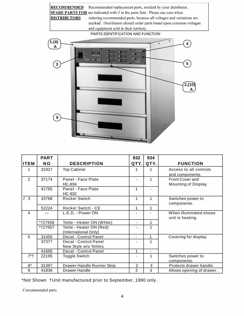
1 31927 Top Cabinet 1 1 Access to all controlsand components.
2 37174 Panel - Face Plate - 1 Front Cover andHC-934 Mounting of Display.
41765 Panel - Face Plate 1 -HC-932
3 43768 Rocker Switch 1 1 Switches power tocomponents.
52224 Rocker Switch - CE 1 14 --- L.E.D. - Power ON - - When Illuminated shows
unit is heating.*†27658 Telite - Heater ON (White) - 1*†27657 Telite - Heater ON (Red) - 1
(International Only)5 31455 Decal - Control Panel - 1 Covering for display.
37377 Decal - Control Panel - 1New Style w/o Telites
41695 Decal - Control Panel 1 -7*† 22195 Toggle Switch - 1 Switches power to
components.8* 31397 Drawer Handle Runner Strip 2 3 Protects drawer handle.9 41836 Drawer Handle 2 3 Allows opening of drawer.
*Not Shown †Unit manufactured prior to September, 1990 only.
4

*Not shown.
5

18 31483 Probe Bracket 1 1 Mounting for probe. 19 31421 Bearings 4 6 Keeps drawer in alignment to
cabinet side. 20 31357 Spacers 4 6 Spaces bearing from cabinet. 21* 49605 Power Cord Assy. - CE 1 1 Transfers electric power to
31993 Power Cord Assy. 1 1 units. (Pin + Sleeve)
31584 Power Cord Assy. - 240V 1 1 (Twist Lock)
48240 Power Cord Assy. 1 1 Right Angle - 932
22* EF02-044 Strain Relief 1 1 Attaches power cord to unit. 31562 Strain Relief (Int’l. Only) 1 1 EF02-076 Strain Relief 1 1
23* 53821 Cabinet Enclosure ws 1 Protective cover. 54056 Cabinet Enclosure (120/240 50 cycle) 1 -- 53961 Cabinet Enclosure (120/240 60 cycle) 1 --
*Not shown.
6
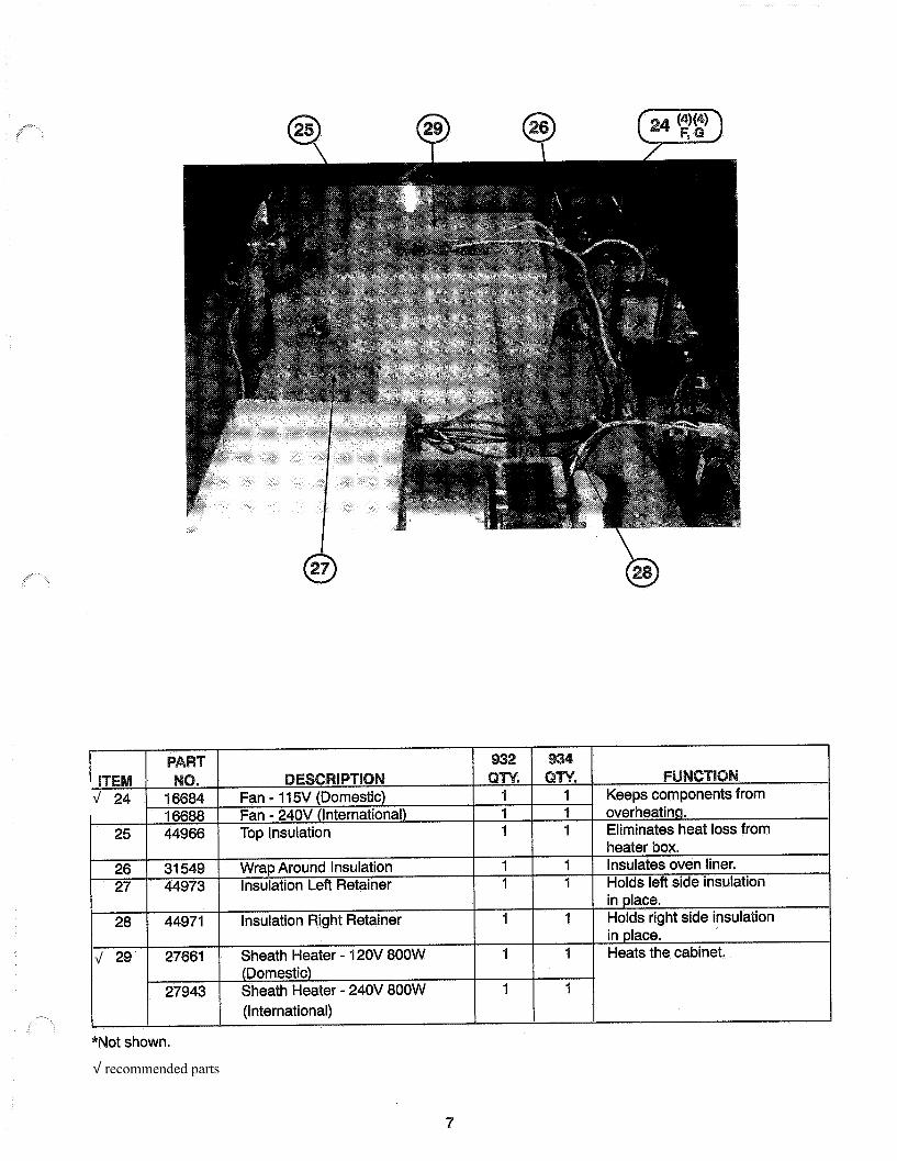
26 31549 27 44973
28 44971
29 27661
27943
*Not shown.
Wrap Around Insulation Insulation Left Retainer
Insulation Right Retainer
Sheath Heater - 12OV 800W (Domestic) Sheath Heater - 240V 800W (International)
1 I 1 1
1 1
1 1
1 1
Insulates oven liner. Holds let? side insulation in place. Holds right side insulation in place. Heats the cabinet.
7
*Not shown.

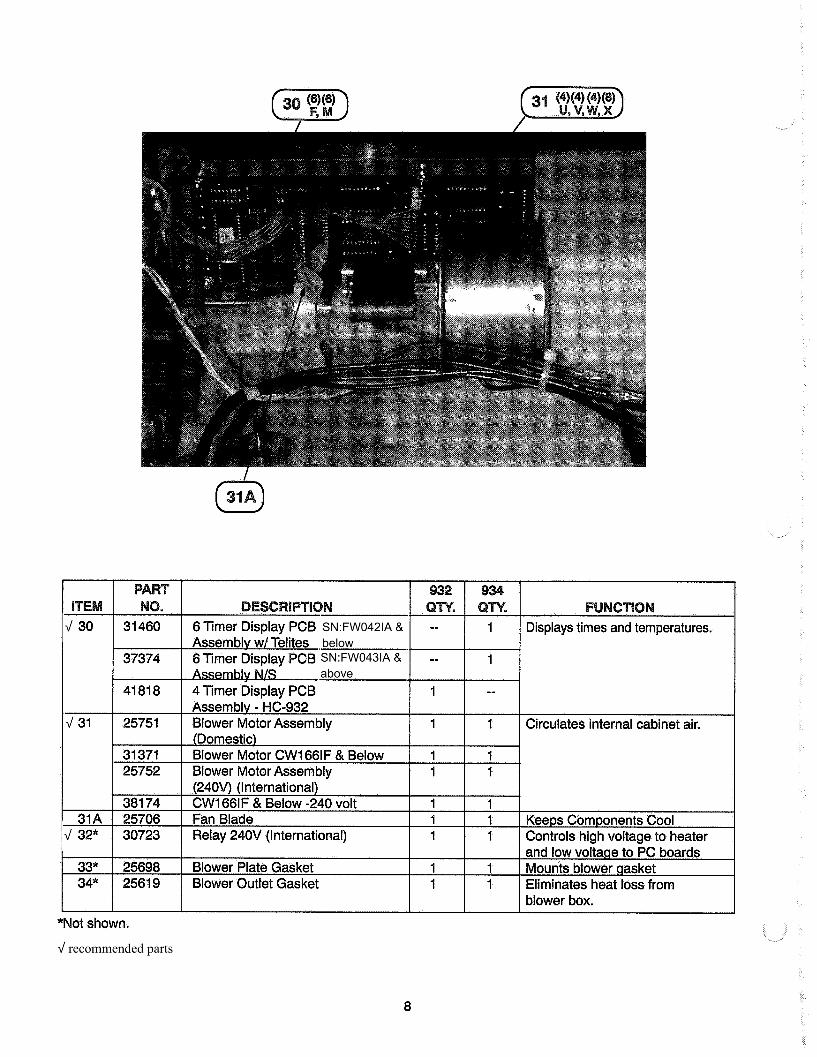
SN:HW050lJ and below 37367RB Control Assembly NS
w/o Telites SNFW042lA and above
41821 RB Control Assembly HC-932
31369 115 VI240 V Relay TS22-006 Transformer 115V
(Domestic) 28979 Transformer 240V
-- 1
1 --
1 1 Routes power to the heater. 1 1 Reduces voltage to 12 volt.
1 1
37 38
39
*40
*41
(International) 36210 Replaceable Beeper 1 1 Sounds a tone when a button
is pressed and at the end of a timing cycle.
48856 1 1 Reduces electrical disruptions -CE Part to the PC boards.
52080 Power Cord Filter - CE 1 1 Reduces electrical disruptions I to the PC boards.
*Not shown.
9

*Not Shown
10
The Introduction and Installation sections of this manual should be read before operating the cabinet.
This section contains an explanation of all con- trols and components and information on oper- ating procedures and daily maintenance.
Heated air inside the cabinet is circulated upward to the cabinet roof and over a heating coil. The heated air is then forced downward through a duct located in the rear of the cabi- net. The heated air is dispersed over and under the product from openings in the rear of the cabinet liner. These openings are varied in size to promote uniformity of heated air through- out the cabinet.
Place the power switch in the ON position and lect either A or B mode by de button for A or the DOWN
The display will increase in temperature, in- dicating that the cabinet is heating. When the operating preset temperature is reached, the display will read 165OF 2 5OF. (74OC + 3OC) in the A mode, or 185OF f 5OF (85OC k 3OC) in the B mode.
1. e the power switch to the OFF posi-
2. Disconnect the electrical supply to the cabinet.
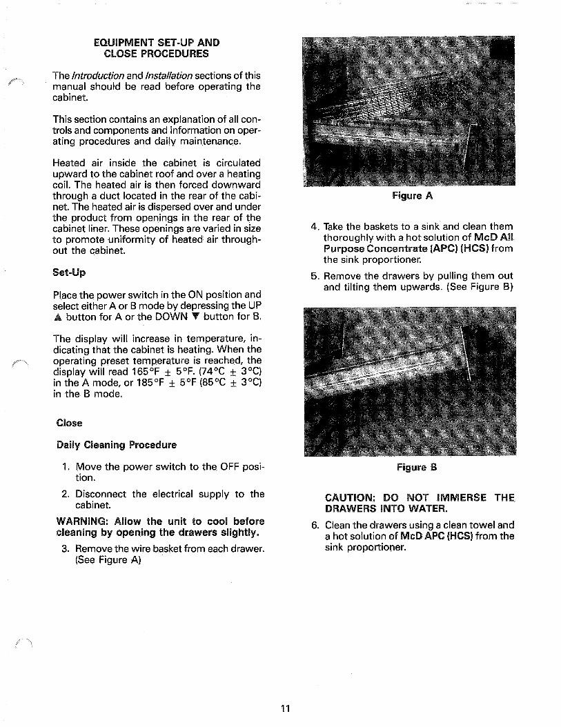
3. Remove the wire basket from each drawer. (See Figure A)
11
4. Take the baskets to a sink and clean them
5. Remove the drawers by pulling them and tilting them upwards. (See Figur
6. Clean the drawe a hot solution of sink proportioner.
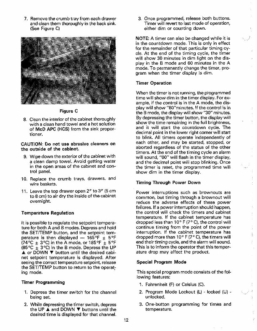
7. Remove the crumb tray from each drawer 3. Once programmed, release both buttons. and clean them thoroughly in the back sink. Timer will revert to last mode of operation, (See Figure C) either dim or counting down.
8. Clean the interior of the cabinet thoroughly owel and a hot solution ) from the sink propor-
9.
10.
11.
Wipe down the exterior of the cabinet with a clean damp towel. Avoid getting water in the open areas of the cabinet and con- trol panel.
Replace the crumb trays, drawers, and wire baskets.
Leave the top drawer open 2” to 3” (5 cm to 8 cm) to air dry the inside of the cabinet overnight.
da
It is possible to regulate the setpoint tempera- ture for both A and B modes. Depress and hold the SET/TEMP button, and the setpoint tem- perature is then displayed - 165OF f 5OF (74OC f 3OC) in the A mode, or 185OF + 5OF (85OC f 3OC) in the 6 mode. Depress the UP
or DOWN button until the desired cabi- net setpoint temperature is displayed. After seeing the correct temperature setpoint, release the SET/TEMP button to return to the operat; ing mode.
er ra
1. Depress the timer switch for the channel being set.
2. While depressing the timer switch, depress the UP and DOWN buttons until the desired time is displayed for that channel.
: A timer can also be changed while it is countdown mode. This is only in effect
,,
for the remainder of that particular timing cy- cle. At the end of the timing cycle, the timer will show 30 minutes in dim light on the dis- play in the B mode and 60 minutes in the A mode. To permanently change the timer, pro- gram when the timer display is dim.
When the timer is not running, the programmed time will show dim in the timer display. For ex- ample, if the control is in the A mode, the dis- play will show “60”minutes. If the control is in the B mode, the display will show “30” minutes. By depressing the timer button, the display will show the time remaining in the full brightness, and it will start the countdown cycle. The decimal point in the lower right corner will start to blink. All timers operate independently of each other, and may be started, stopped, or aborted regardless of the status of the other timers. At the end of the timing cycle an alarm will sound, “00” will flash in the timer display, and the decimal point will stop blinking. Once the timer is reset, the programmed time will show dim in the timer display.
er
Power interruptions such as brownouts are common, but timing through a brownout will reduce the adverse effects of these power failures. If a power interruption should happen, the control will check the timers and cabinet temperature. If the cabinet temperature has dropped less than 1 O” F (7 O C), the control will continue timing from the point of the power interruption. If the cabinet temperature has dropped more than 10 O F (7 O C), the timers will end their timing cycle, and the alarm will sound. This is to inform the operator that this temper- ature drop may affect the product.
Special e
This special program mode consists of the fol- lowing features:
1. Fahrenheit (F) or Celsius (C).
2. Program Mode Lockout (L) - locked (U) - unlocked.
3. One-button programming for times and temperature.
12
To enter the special program mode:
1. Turn the power switch to OFF
2. Depress and hold the SET/TEMP button while turning the power switch to ON.
3. Release the SET/TEMP button.
er witc
Upon entering the special program mode, the temperature display will be blank. Timer 1 switch will change from F for Fahrenheit to C for Celsius. This will be shown in the Timer 1 display.
er witc
If there is a programmed time and setpoint temperature for all three timers, you have the ability to lock these cycles in to avoid anyone from changing the times and temperature. Enter the special program mode. There will be a U shown in the timer 2 display. Depress the timer 2 switch and display will read L for lock. To change any preset times and temperature to U. You are now able to make changes as desired.
To turn OFF or ON the beeper or strobe light, enter the special program mode. By depress- ing the timer 3 or 4 button, the display will toggle from B, S, BS, or blank. B indicates the beeper will sound at the end of any timing cycle. S indicates no beeper, but the strobe light will come on at the end of a cycle (if applicable). BS indicates both beeper and strobe will come on, and a blank display
li -ii
To preset the holding cabinet to McDonald’s specifications, enter the special program mode. Depress timer 3 or 4 button. The temper- ature display will read “INI” briefly and return to normal special program mode. All timers will be set at 60 minutes in the A mode and 30 minutes in the B mode. The setpoint temperatures will be 165”F+5”F (74”Cr3”C) in the A mode, and 185”F+5”F (85”C-c3”C) in the B mode. To exit special program mode simply turn the power switch to OFF and then ON again.
ca
18”widex24-1/8”deepx21-1/16”high(46 x 61 x 53 cm). Model HC-934
18”widex24-1/8”deepx 16-‘l/16”high(46 x 61 x 41 cm). Model HC-932
Equipped with 3 channel II-3/8” wide x 18-7/8” long x ‘l-1/8” deep wire baskets (29 x 46 x 26 cm). Model HC-932 only has 2 baskets.
Shipping weight - 135 pounds (61 kg) Model WC-934
Shipping weight - 1 IO pounds (50 kg) Model HC-932
indicates no beeper and no strobe.
Heater not working. Check heater and replace if needed. 1 Blower not working. 1 Check blower and replace if needed. 1
13
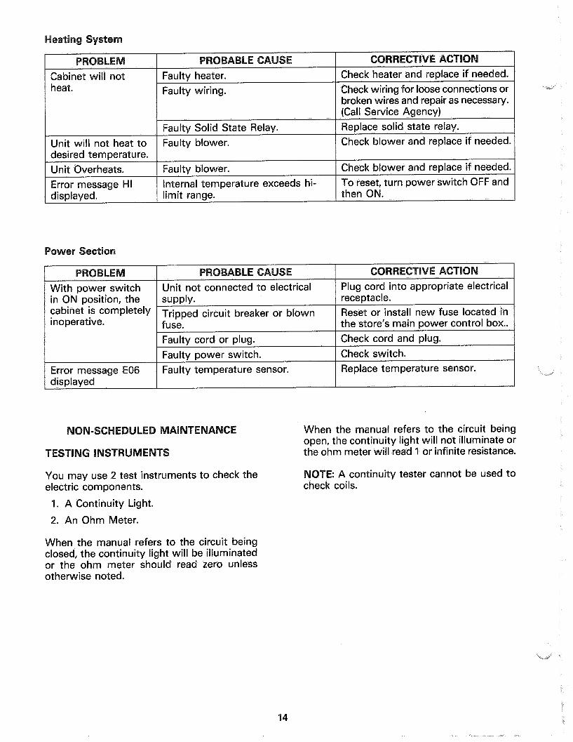
Cabinet will not heat.
Unit will not heat to desired temperature. Unit Overheats. Error message HI displayed.
Faulty wiring.
urn power swltc
cabinet is completely
temperature sensor.
When the manual refers to the circuit being open, the continuity light will not illuminate or the ohm meter will read 1 or infinite resistance.
You may use 2 test instruments to check the electric components.
1. A Continuity Light.
2. An Ohm Meter.
: A continuity tester cannot be used to check coils.
When the manual refers to the circuit being closed, the continuity light will be illuminated or the ohm meter should read zero unless otherwise noted.
14
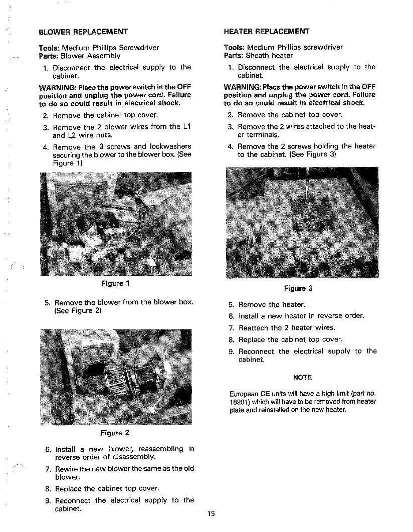
: Medium Phillips screwdriver Sheath heater
1. Disconnect the electrical supply to the cabinet.
2. Remove the cabinet top cover.
3. Remove the 2 wires attached to the heat- er terminals.
4. Remove the 2 screws holding the heater to the cabinet. (See Figure 3)
s: Medium Phillips Screwdriver : Blower Assembly
1. Disconnect the electrical supply to the cabinet.
2. Remove the cabinet top cover.
3. Remove the 2 blower wires from the Ll and L2 wire nuts.
4. Remove the 3 screws and lockwashers securing the blower to the blower box. (See Figure 1)
emove the blower from the blower box. (See Figure 2)
5. Remove the heater.
6. Install a new heater in reverse order.
7. Reattach the 2 heater wires.
8. Replace the cabinet top cover.
9. Reconnect the electrical supply to the cabinet.
European CE units will have a high limit (part no. 18201) which will have to be removed from heater plate and reinstalled on the new heater.
we
6. Install a new blower, reassembling in reverse order of disassembly.
7. Rewire the new blower the same as the old blower.
8. Replace the cabinet top cover.
9. Reconnect the electrical supply to the cabinet.
15
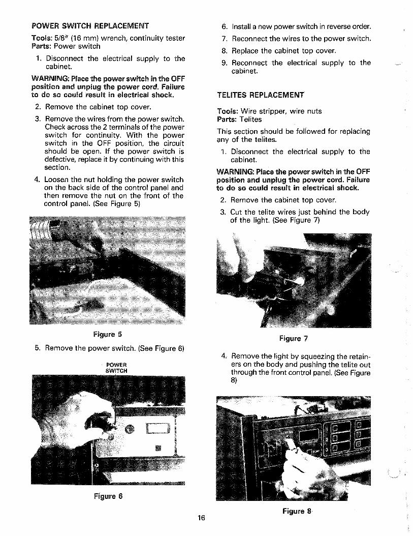
: 5/8” (16 mm) wrench, continuity tester : Power switch
1. Disconnect the electrical supply to the cabinet.
2. Remove the cabinet top cover.
3. Remove the wires from the power switch. Check across the 2 termi Is of the power switch for continuity. ith the power switch in the OFF position, the circuit should be open. If the power switch is defective, replace it by continuing with this section.
4. Loosen the nut holding the power switch on the back side of the control panel and then remove the nut on the front of the control panel. (See Figure 5)
5. Remove the power switch. (See Figure 6)
POWER SWITCH
6. Install a new power switch in reverse order.
7. Reconnect the wires to the power switch.
8. Replace the cabinet top cover.
9. Reconnect the electrical supply to the cabinet.
s: Wire stripper, wire nuts : Telites
This section should be followed for replacing any of the telites.
1. Disconnect the electrical supply to the cabinet.
2. Remove the cabinet top cover.
3. Cut the telite wires just behind the body of the light. (See Figure 7)
re
4. Remove the light by squeezing the retain- ers on the body and pushing the telite out through the front control panel. (See Figure 8)
16

5. Install the new telite by pushing it through the front of the control panel until it snaps securely into place.
6. Strip the ends of the cut wires and connect them to the new telite with wire nuts.
7. Replace the cabinet top cover.
8. Reconnect the electrical supply to the cabinet.
s: Wire stripper, wire nuts, Phillips screw- driver
s: Fan
1. Disconnect the electrical supply to the cabinet.
2. Remove the cabinet top cover.
3. Cut the fan wires 6” (15 cm) from the fan. (See Figure 9)
4. Remove the nuts from the 4 screws hold- ing the fan to the cabinet. (See Figure IO)
5. Remove the fan.
6. Install a new fan in reverse order.
7. Strip the ends of the cut wires and connect them to the wires of the new fan with wire nuts.
8. Replace the cabinet top cover.
9. Reconnect the electrical supply to the cabinet.
: 3/8” (10 mm) wrench or socket driver . Solid State Relay
1. Disconnect the electrical supply to the cabinet.
2. Remove 2 nuts holding mounting bracket and remove. (See Figure 11)
3. Disconnect wires from solid state relay. (See Figure 12)
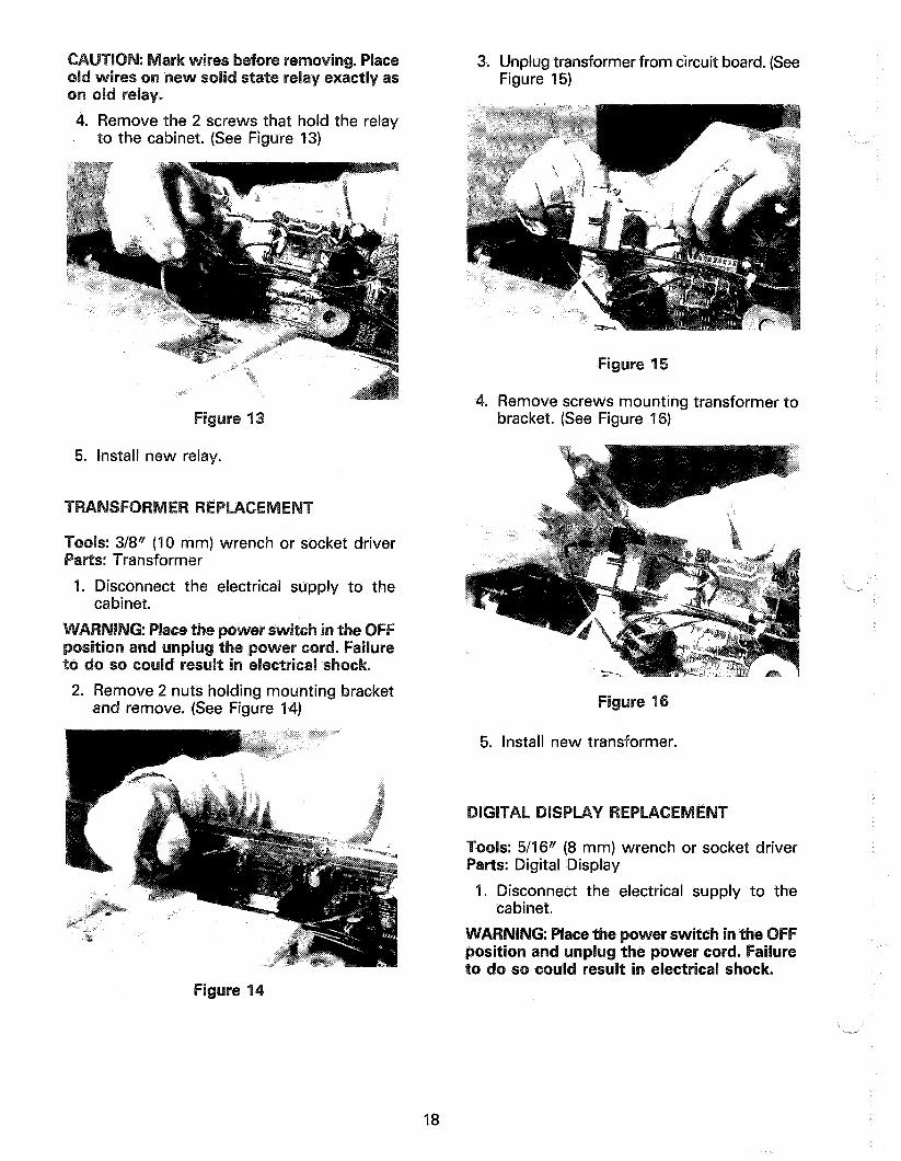
4. Remove the 2 screws that hold the relay to the cabinet. (See Figure 13)
3. Unplug transformer from circuit board. (See Figure 15)
4. Remove screws mounting transformer to bracket. (See Figure 16)
5. Install new relay.
: 3/8” (10 mm) wrench or socket driver Transformer
1. Disconnect the electrical supply to the cabinet.
2. Remove 2 nuts holding mounting bracket and remove. (See Figure 14) re
5. Install new transformer.
: 5/16” (8 mm) wrench or socket driver Digital Display
1. Disconnect the electrical supply to the cabinet.
: Place t tion and unplug t o so could result
re
18

2. Unplug circuit board from display. See Figure 17)
2. Remove the top drawer from unit. (See Figure 19)
3. Loosen the 6 nuts holding the display to the cabinet and remove.
. Install new digital display and carefully tighten nuts.
/ -
In the event the temperature sensor becomes faulty, an error message E06 will be displayed. Turn power switch OFF and then back ON. If the error message E06 is still displayed, the temperature sensor must be replaced.
river, 5/16N (8 mm)
: Temperature Sensor
3. Loosen 4 screws holding xcess panel and remove panel. (See Figure 20)
4. Loosen 2 nuts mounting temperature sen- sor to bracket and remove from bracket. (See Figure 21)
CRACKED
PROB
19

Unplug sensor from board and pull out 3. Remove 4 screws and spaces securing the from top of unit. (See Figure 22) circuit board to the cabinet. (See Figure 24)
6. Install new sensor in reverse order.
s: Phillips screwdriver : Circuit Board
1. Disconnect the electrical supply to the cabinet.
2. Unplug circuit board from digital display. (See Figure 23)
4. Install new circuit board and carefully tight- en screws.
5. Plug new circuit board into the digital display.
s: Continuity tester s: Power Switch (Rocker)
1. Disconnect power to unit,
2. Remove the cabinet top cover.
3. Remove the wires from the switch. Check across the terminals - top and bottom ter- minals on the left side of the switch, and top and bottom terminals on the right side. In the ON position the switch should show continuity. If switch is defective, replace it and proceed with procedures. (See Figure 25)
re
,--
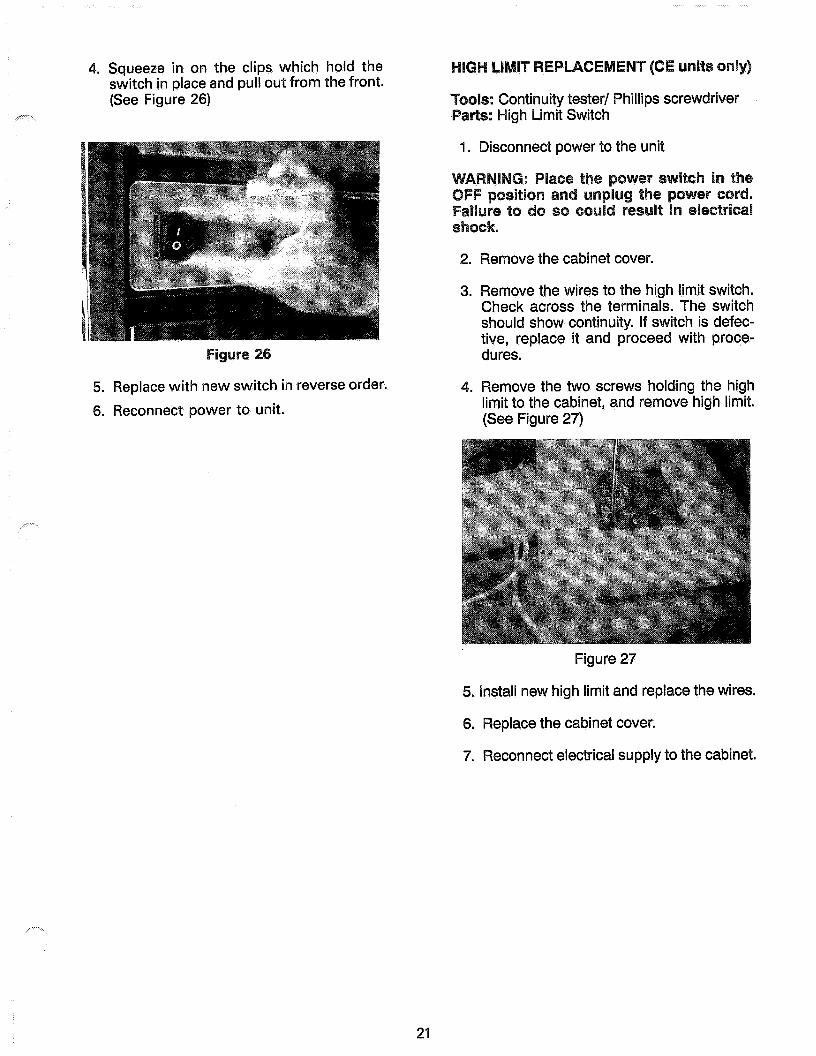
4. Squeeze in on the clips which hold the switch in place and pull out from the front. (See Figure 26)
5. Replace with new switch in reverse or 6. Reconnect power to unit.
21
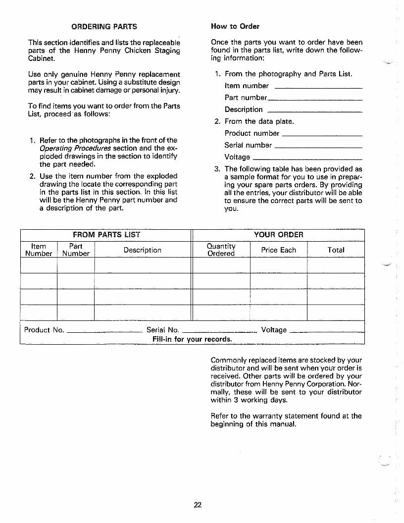
: Continuity tester/ Phillips screwdriver s: High Limit Switch
1. Disconnect power to the unit
2. Remove the cabinet cover.
3. Remove the wires to the high limit switch. Check across the terminals. The switch should show continuity. If switch is defec- tive, replace it and proceed with proce- dures.
. Remove the two screws holding the high limit to the cabinet, and remove high limit. (See Figure 27)
Figure 27
high limit and replace the wires.
6. Replace the cabinet cover.
7. Reconnect electrical supply to the cabinet.
This section identifies and lists the replaceable parts of the Henny Penny Chicken Staging
Once the parts you want to order have been found in the parts list, rite down the follow-
Cabinet.
Use only genuine enny Penny replacement parts in your cabinet. Using a substitute design may result in cabinet damage or personal injury.
ing
I,
information:
To fi items you to order from the Parts List, oceed.as f s:
I.
2.
2.
Refer to the photographs in the front of the Operating Procedures section and the ex- ploded drawings in the section to identify the part needed.
3. Use the item number from the exploded drawing the locate the corresponding part in the parts list in this section. In this list will be the Henny Penny part number and a description of the part.
From the photography and Parts List.
Item number
Part number
Description
From the data plate.
Product number
Serial number
Voltage
The following table has been provided as a sample format for you to use in prepar- ing your spare parts orders. By providing all the entries, your distributor will be able to ensure the correct parts will be sent to you.
Commonly replaced items are stocked by your distributor and will be sent when your order is received. Other parts will be ordered by your distributor from Henny Penny Corporation. Nor- mally, these will be sent to your distributor within 3 working days.
c,.,
Refer to the warranty statement found at the beginning of this manual.
22
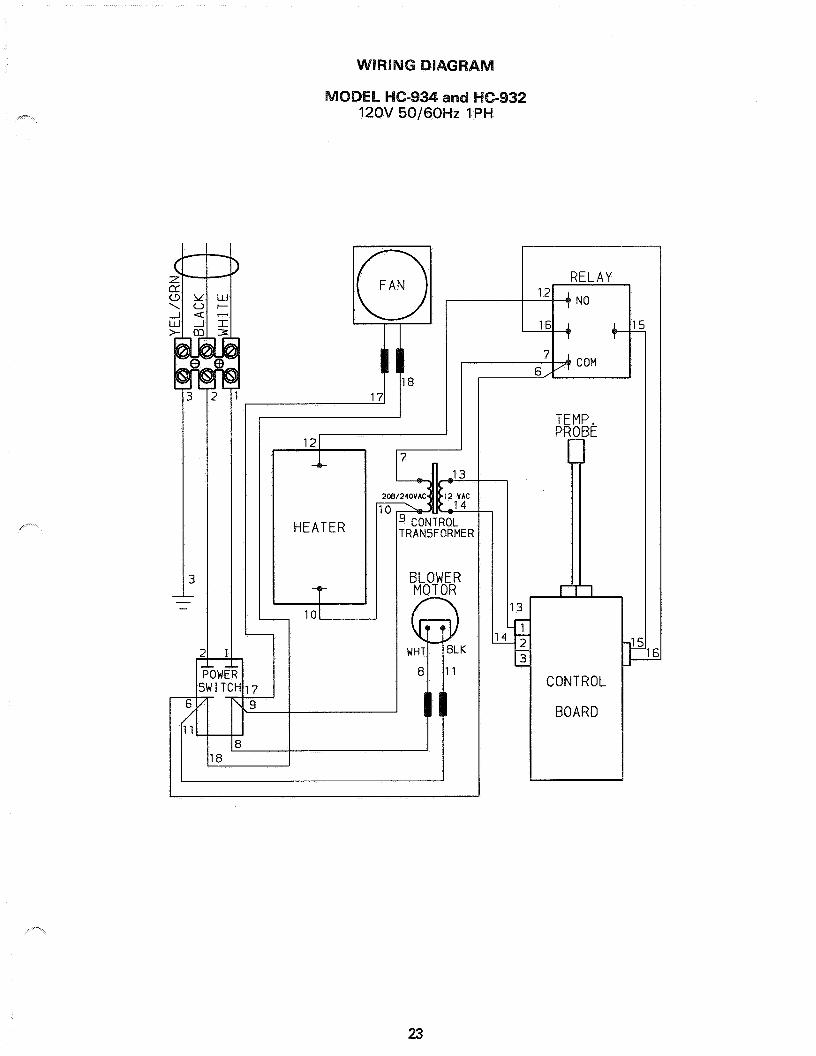
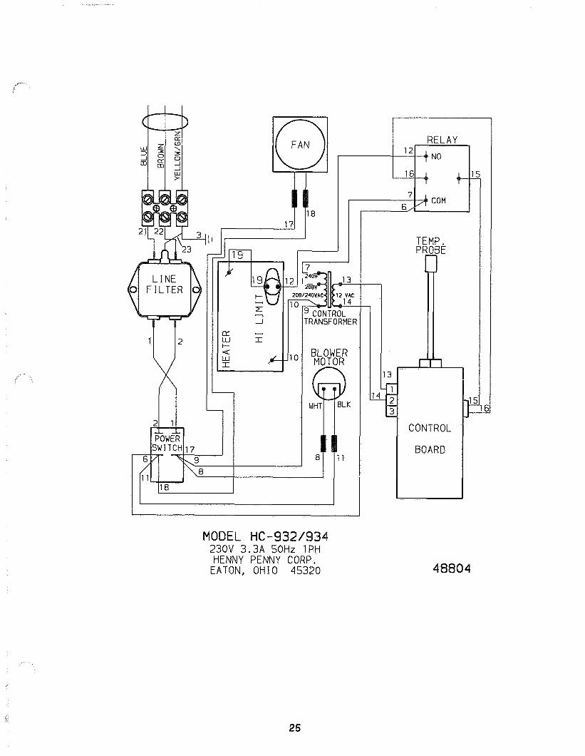
c- 12OV 50/60Hz 1 PH
HEATER
TEMP. PROBE
23
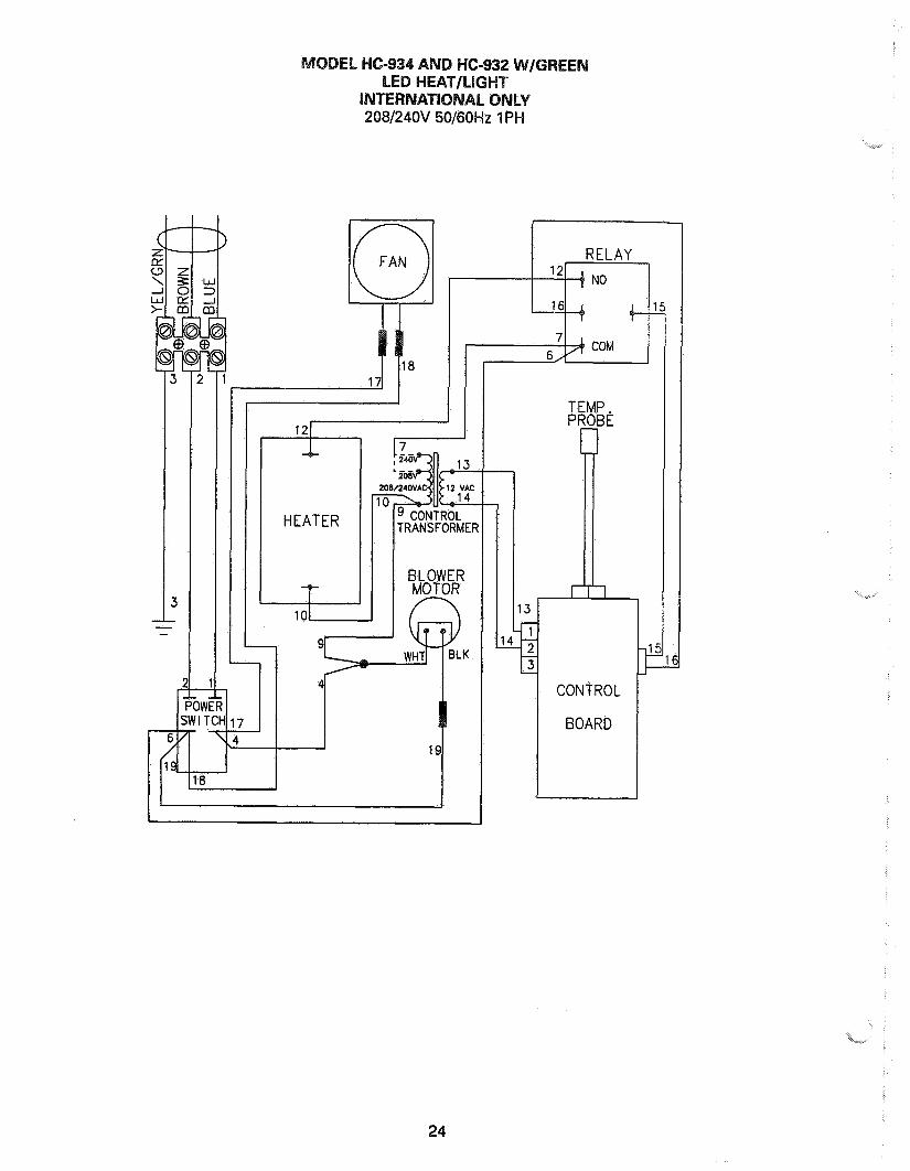
208/24OV 50/60Hz 1 PH
I -
1 ,l L
1 Y WliI ” ILK
1 I I -
)W I I SWITCH17
6 COM
TEMP. PROBE
rl
Ii 13
1
HEATER
101
TRANSFORMER
24
i”-“
,--
OOEL HC-932193 230V 3.3A 50Hz 1PH HENNY PENNY CORP.
EATON, OHIO 45320
TFMF ?OE
CONTROL
BOARD
25
�� ����������� �������������� �������� ��������������������
�� ����������� ��������������������� ����!��"!�� ��������#$��%&����������'�'�''
�� ������������������� �&'���� ����(����!���� �)��*�+�����,-�������'����'�%��'%�
�� �������������� ���$��.����*/�0���1!����/�!� ����,-�����'�2'��������&�'�&2��������&%��%��%
�� ����������������������������3���������*.+!/,��� ����*�����"��%%���'�&�� �%����%�
� �!"#��$%�����%$��&2����4�)���5�!��.�)�!�#�� 67�!�� 0����&��&����2%&��''�������2%2��''�
'� ()����*���� ��������)�����.� ���#�������&�1!��5��������"��2��'������'�������,8�9!����������&''�&�'2
+� �����!��,"#��$%���'2���:���)��������)�������(���������:��&&������%��%�2������������%'�&��'
-� ��������!��,&���%���� �������3!�����*��"�+/��.�!����;���������&��������%2
�.� )�� ���������� �)� ��������*.+!/��'�������!������,#���������2��2��������'�&��'������%������&�%����&
��� /������������������ �"�:��5�<�����=������"!������������&�&���%%�%���������������2�
��� 0�(�1�&���,���������������� �&��'�9����.����5���$!6(!��=3���%�2�������'���&�� �!6���2�&���&����&�8!�����������2�&��'���2��&=3�9!���������������'��
��� /���2������������������� �"�:��5�<�22&�5��6��*.!6��3������������%�������
������������������� ����������������������������� ���������������
��� /�������$$�&���2�-������ �6(.����$,�����&�2�����'���&&�,!�.������$,�%�����&��%&�� ���%���$$�&��%���.������� �.,!�.������$,��'����%�����&��%&��
��� ��������$$�&��%$��&����1!��� !���������1!�����:��&�����2�'��&�%�����������'%���2%�
� � ����"#��$%�����������"��������+/�"�:��5�<��&����>�(�&����3� ��������?-�&����������%�'�����=4� ������ %�'���''
�'� 3����,���4��������� ����''� 5������#� ��3����!�� �� &�����'�&�� �%������
�+� 5*(�����������������"!����+������5!/��9���&��&�2������2�2���
�-� !��,���� ������������ ��%���5!���!/�5���5 ��!����������3�%���2��&'��&�2���&���&'��&�2�'2&�
�.� �"������#!������0��=������� :�%���%���&'�%�%���&���%%&�������2'�����
��� ������$$�&������ ������9��)��������)��3������)�����)�'���&������%%&�&��%
��� ��6���$$�&&2��8 ��!�������5��*����8!������� ���2����%������&�����
��� /��������1�7������������ �����,���.�3 ������3!�!/������3�'���%���'�� ����2'��
��� �8�"����$�������������� ��@�A�1!������*�����$4�'%������'��%&��'222
��� /���4���,�������&&�����9�� �2�.� ���:��!.�6!�#��/�� :?� '���2�&����%���'���
� � /*�������22���9�� �%�������� ���� 0:�!�.��� ?�� %%�%��2���� '%������=4� 2���'%������
�'� )(5&���%��������*.+!/� �� �������,�+�5��*.����� ,�������%���� %�2���%�
�+� ��,�9�����4�1����������$$�&����&������9�77�)�!���!������!����,1�%������������&��'��
�-� 1�������0��,*��������9��#���������1�*��+�����#:������������'%������������������%�
�.� :(���$�������/
��� �)"�3�8�:�����9����0������9!/$�6(��� �B� ����&�&���� &2%�%22�
��� 9�������"#��$%������$��&��9�����%����� �.�!���3!���#��/��C$��&����������%%����&������2���2���
��� 5;�9� �<���������2��2�9���� ;!���/��+/� ���� ���?�����9� 2���������� &�%��2'��&���� %�%��2�'� =4
��� 5����������4���$$�&������1�� ���*�6��/��� �����(��!����9�22��%���2��2���������''�� ����&�%�
� � 0������)� �7� ������������� �� ��2&���#!7���5� ��!���!/+�����#�2&�&�������'�������
�'� ���0��������%$��&��������� �!��������� �����!��!��!��#�2�'�&�'�&��2'2���%�
�+� 5��&��!��,���� ��'�&�� ��!���)� ��� &���.�����,�&%��%���2����������
�-� 5������&()��� ���'�9����=� ��.����0!��(���������������2����������
�.� #���������#�66����!�� ������� D1E �(6���� �##�1�%����� ��� ����!�� ���*.���0���?��<������ $,� � �'2�2��%����&%��''�
��� ��<��������������� �� �"�:�� 5�<� &��&5�<���%?�)��� �&;������!�� $4� ''2����%��� �'��2'''
��� 5�$�8��������������������#����*������ ������$4�''����'����2&%�%���
��� �8�� ������,��&��������.���1�6��������7���!#!�!�!�$�3��%�&����&���'�����7���!��5�����.�#�� 67�!� !����7!���!��!��.�+!��- �����D�,�9��$�����������
��� 5�&���!���=������ �����6�.��(��)��5�!6(�����:��!���#!�!�!�3%$� &�2����'2�������:��!����� �����!���!�� !����6��"��������
��� /�=����5�&���8����&'���) ��5� �*;���������3! ����F �7����#!�!�!���$��8����&��'����%�'�F �7������/�
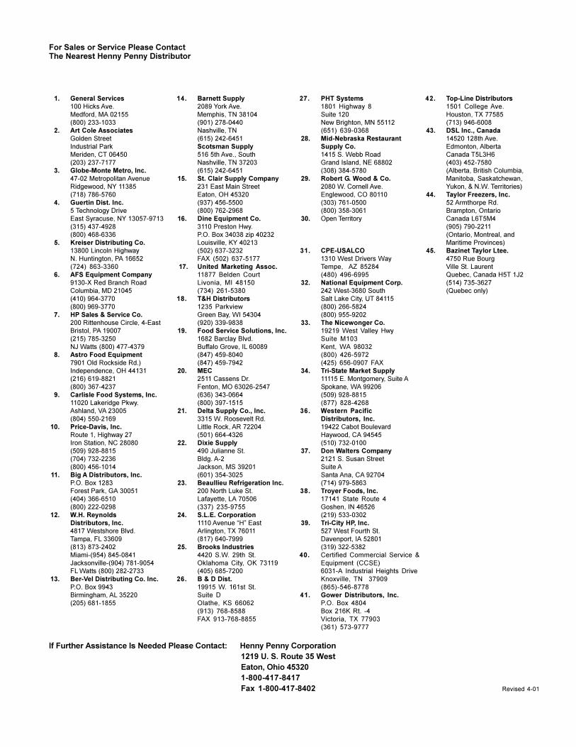
���������������������������� ������������� ������ ����������������� �!�"#��#�$�����%&�'��(����)�*����+&% ,�-.,,-+�/-.+�/��0��-.,,-+�/-.+, ����������


�������������� �� ���� ������������ ��������������������������� �!���������"#�$��%� �&���'��()��'*�+&���'��(�)(
����� ������������������ �� ���� ������������
������� ������� !,,�-����-��.� ������������/.���$� ����0����������$��� �������1��� ��#%�0��$������2�3 ��''�(��4�3 ������5�6������+ *�� -�#�$��%� �&����7�8�('�(*�+&����7�8�('��)�
������������������ �� *�-�� / ��� ���� �$���6�� �
��9���%��� �5�����:���� ��������� �5���� ��"��������"#�$��%� �&������)����*�+&������)��'�
�� ���������� � ���� ������������������7�+-$��� 3����������-�8#���$��;���6� ������$��������9�����������5��6� �*4����')#�$��%� �&���'�)���*�+&���'�)���
�� ������ �!5"<
=������5�%6����<���>����7!����8�"3�� �"$3����#�$&�����������?���*�+&����������(�
�� �������� !����-���"�
"�3��� �"$����@����)�(��*$�����<�� ���"���� �"�3� �� �#�$��%� �&�7���8�'�()�*�+&�7���8�'�(��
(� � ������A�4��4� ���������4�����'����2�-�������������������9���������� �� � �"�����$��#�$��%� �&�(�'��'��'��*�+&�(�'��'��'��
!�"����'� 5�%�66���A�$�$������� 3
!$����$�-��������!��<�+�����5� �6� ��������,�<�%��� #�$��%� �&��'�������*�+&��'������')
!�� ���� ")� ��,,� � / ��� ���� �$� 4���
�(��<��$��%� ������B��� 1�1���$�@���%�*$���:%�1�����:%�1� �<� 3$����%#�$��%� �&�))�)(���'*�+&�))�)('�(�
!�� ���� � 3�$� ������9�2�
/ �������$���1�#��0�1�%�,*���3��,��$�� ���<�(��" �B���� �7��$��>18#�$��%� �&����)����''*�+&����)���'�
������ ���������������������������������1��2
!��#���� ���� ��;���6� ��*���������-�
���!$����<�$�-��))?��)��������� ��:����$����<��@�$#�$��%� �&����'(���'*�+&�����'(���((
!� ������� ���������"/C
��"�����!0���-%����,����(� �<�$3����#�$��%� �&���������(��'�*�+&���������(�((�
�"������ /5"��
5� ��$�5� ���������������� -���� ���3� ��%�$�#�$&��(��������?�''*�+&��(��'�)�('
�"������ <� �� *��������-�� �����-��
*$���� �)?* �=�� 3�=����%� 3/ �������$�<$�3� �9������ 3��������D�B$�� �<�� �D�B$�� ��� 3�D� 3#�$��%� �&�)��'�(�(�(*�+&�)��'��)��
����������� / �������$�#��$���4����
#�� ������$��� �9�6����(���"��������"�������'�<�3����:��� ���$�60��#�$��%� �&��'�7�8�����(*�+&��'�����(��
��������� 9�B���1
!����>��5��#�����������!����>� ��������#�$��%�%�&��)���'����*�+&��)���'����
�$�� �(� "5*��%����,�����4���
��"�������6���������!��<�+����9�-���� � ������#�$��%� �&���'�����)*�+&���'����))
�#��"���������'� �����
"�3� �� �1����E���'�����3����'�E���� ����<4/�#�$��%� �&����(('��(�*�+&����(('���'
%�����&�)� / ���F������"���
5����3����)�(��<�� �0�:� 6��1��:D�(�#�$��%� �&���������*�+&����������
��������� �;�� ��-�������4����
����$��$��� ;��������F�� ���$�60���((���� -� ��-�����#�$��%� �&����')��'))*�+&����')�����
� $���� �� �#������� ���
�"���6����������5�����,�<��$�� 3�G)��H�G(������ � �3���#�$��%� �&���7�8�''(��?'(����*�+&���7�8�'�(��)
� �������� �������>��"�
#�% �1�����(���#�$$� ����� ��#�$��%� �&���'�(���*�+&���'�(����
'��������� 5� �$�����!�
��!��<�+��'��$��1�>��(�*���2� ��� �*� $� �#�$��%� �&���)�)''�*�+&���)�)''���
'�������� :�,,���� � / ��� ���� �$� ��
5������$�7:/58���-��.�-��������$�6� -����%�6� �����%�������.���<��������'��5��-;� <������$����+ �*�� -�#�$��%� �&�7��8��)�*�+&�7��8��'�'���
(�����$��� ���>�1�DF
��$$� ���*�$����:�)��������� F��6� �#�$��%� �&�������(�'''*�+&�������(�)���
("������ :�#�F%� �
�((���"0$��������D� �����������!��<�+���'�"--���� �� 6� �� �F%� �#�$��%� �&������������*�+&����������)
(������(� :�6����-�� ��"�
(������� ��������"�%� ������ �F���-�#�$��%� �&���������?��*�+&���������)
(���'� ��-�,�-�#�-% �-�$� �����-� � / -�
9�B���66��-��$�<��$�� 3G�'�������( �������<�<����3��� �F��6���(���#�$��%� �&�('�(���*�+&�('�(������
��������)� � 3$�$� ������<�2�
��������3�)� �����0���������:"���������6 ���$$� �#�$��%� �&��������''*�+&�����������
��� �)�� ��� <� �� *��������-�� �����-��
*$���� �)?* �=�� 3�=����%� 3/ �������$�<��$�� 3�G��� 3���������D�B$�� �<�� �D�B$�� �� 3�D� 3#�$��%� �&�)��'�(�(�(*�+&�)��'��)��
�� ��$�� ����+� �����-�
����� 9�3�1���-��D�����%�4�>���������� 3���#�$��%� �&��(�(��((��?)��(�*�+&��(�(�)��(�
���������� "��D��$��� ����*�
<������%�$����)������1>���1 ��!�<�+��('/-�$� �#�$��%� �&�����(�*�+&�����(��
�������� "/���"�="
#�������6�$�+ ���!2F���<����� �3���<� 3�$�����(� �/ ���#�$��%� �&���)((''�'(*�+&���)((''�'(
/ �.$����,��3������ �����'�9���>����0%��%�5��3:�����F� >9�B�:�$%����� �/ ���#�$��%� �&�������'�(��*�+&�����(���)�*
������ ����� ��#��F�6�
A4�� ����� <$��$������ ����<$�-1�/!"���9����'D�$����F��� 3����6��A�1��������� �/ �� ����#�$��%� �&�(�������''
���������(�����)��*�+&�(��������)(?���'''
���������� 5���� �*�����;���6� ��4���
F��1� �<��� �������1���������:� ��$1 �4���%���� ��/��$� �#�$��%� �&��������((*�+&��������'
����$��� "$$�3�����4
������5�������� ��������#��� � � /��$�#�$��%� �&���������(�*�+&���������''�
+�����(� #����D�3�������4���
�* � 9������ 9��%�F��� ��<��$�� 3����9��%�F��� ���'�%�6��%� �3�B�1� �#�1��������A��� #�$��%� �&�)���''��)�*�+&�)���''��(�)
+������'� "B���#���� 3����
�!�<�+��(���'"66� �����( �A���� #�$��%� �&��(�(����(�*�+&��(�(����(�
)�����)� !%>� �����������
����*$��� �����A� 3�<��$�� 3�(������-%��� 3���-%�1�����!��<�+���������$���'' �D����#�$��%� �&�)���)����*�+&�)���)'���'
),������ 5�0���1�����$�����$�������
�!�<�+���)�����B�$$������D�B���#�$��%� �&��(��)�)���
����������(��)��(�)*�+&��(��)�����
���� ���-./0

1�������� ����D��-%�
��%$,�� �<��$�� 3D��$�1��5�� ������!�<�+��((�A�� ��%4�0� � #�$��%� �&��(��(��''*�+&��(��(����
1��"������� 5������F�����<�$��-�5�����
:�������/��F��� ���'���)�2�$ ��� �4��%�� ��#�$��%� �&��'��(��)?���*�+&��'��(���
2���$ ����� ������������ ��<%��
�����A�$� ���>� #�6� �!��������� �� �)��D��$��4�6��� 5�$�����#�$��%� �&�(�'')�)�)�*�+&�(�'')�)�(�
5�$����� ��H���<����$��4���
����#%������ �F@����F@��� �5�$��#�$��%� �&����(����)�*�+&����(����(�
2����� � � ������� 75�������� ���� �� �/�$� �
���-%�$$��8�����6�5��������B����<���0� ���������!��<�+���������4���� �5���������/�$� �#�$��%� �&��(�7��8���)��*�+&��(���)��'
2�������� �� ���$�5�+�-��5�����5�+�-������
����6�+���"�������2�����$$�3�3����9���(����$��� ���5�+�-� �:�*���('5�+�-�#�$��%� �&���������*�+&�������'��
��-�,�-5�-����������:��!--��� �� ��"�������2�"���A�� ���$�6�����"����G)����$��A���� ���2�$$����E����� �A�$��-� �5�+�-��������#�$��%� �&����(�����*�+&����('�����
����%�����;�����������$�5��-�����"�������2��$$�����9�����<�����(���(�5����� �=�-��� 5�+�-��������'#�$��%� �&�������(�*�+&������)((��
2�������(� �$�-���
<��$������"�4�4�3%$�6<����(�)�����<�� �������"� ��0������0$� -���5���--�#�$��%� �&������'�����*�+&������'�����
3�,�4�������'� #��$����;���6� ��4�6����
���� �@��$�-�5�����$$� 3�� "�-1$� � �9�B�E��$� �#�$��%� �&�(��7�8��'���''*�+&�(��7�8��'�)��
3��,�$�)� F��$$,�36� � �"���
!��� �>����� ���9(('�!�$��( �9��B��#�$��%� �&��'�7�8�(����*�+&��'�7�8�'��'
������� 5�%�� ��������:��B��%�44�
��!��<�+�))��B� �����������4#"9"#��!*�!5"9#�$��%� �&��()'����*�+&�7�()8�')���'
5�&� ����� #%���;���6� ����6�� �
F��� ��*$��� �:���0%����� ����%�����*����� �D���-%��'�����1���� #�$��%� �&�����'')�'')?�'')*�+&������)'��(?'')�'''
5����� /6����������#�- �-�
��6��-��$������4����A���5��-������"��60����G���4�6���' �����#�$��%� �&������(����*�+&�����'��()�
5"�������� ��� �D���;���6� �������
� ��*$��� �#���<$�3���'(����6������������4����@ �5�1�������� ��%�$���� ��#�$��%� �&�(��)������*�+&�(��)������
5�������� /�� *����
����3����� ����'��������B ����$� �#�$��%� �&��)������'����������((��)�?�(�*�+&��)������'�
5��� ����� ����������$
"2�:������0$�-�)����������4��0�������3�$#�$��%� �&������'�('��(?'?)?�*"C& ����'����)�
5������������ ���3����������$���� �������-�
�!�<�+��)'(�����������3%��������� �� �A�� ����������-������)'(#�$��%� �&�')'')�'�'�*�+&��')''��(�'�
6�����(� #�������F����
�����9���('')��!��<�+��'�(:�%� �I����#�$��%� �&��'��((����*�+&��'���(��(�
��������'� :�$���#�-% �$�3������6� ����"�
��-����( ����� ����-����$���<$���<$�-���" ��-��<�'�%�*$���"����(�<�-%����� �:������6� ��#�$��%� �&��������(�*�+&�����������"������&����5�� ����5��%�B�1� �/ ����(���#�$��%� �&������(�')�*�+&������('��
������������)� ��66��-��$��� ���
:���$��6� �� H� �-� �6���!��<�+����A����%������ �������"��0��#�$��%� �&��((�7�8�(���)�'*�+&��((�7�8�(���)(
���� ����� <����� 3������6�����
�?�����-%� ����'�4�����$6������ #�$��%� �&������)����)(*�+&������)�'�(�
��� �����(� ��6�$�+������4���
<$�-1�� �4��� 3�)#�������%�/ �������$����1����)��� 3�����������#�$��%� �&�(����(���*�+&�(����))��
�%��,��� 7�8������4���<$1�(���"$>� ����/ �������$���6�$�+� ������� 3��������)�)��#�$��%� �&��(�'�����*�+&��(�'��)���
���"�������(�� *�������� J��K
�!�<�+����(�9���%$� ������( ����0$�-��,�����%�",��-�#�$��%� �&����'�7��8�(�(��)� *�+&��'�7��8�(�()�)'
�����(�� "����
#���� �)�)(���<��-�$� � ����� #�$��%� �&���������)*�+&�������)�')�
����1��&�(�� ����������66��-��$��;���6� �
�������$��6� ���������$�D����D����?��$�60� �����4� 1�#�$��%� �&���)'��(�*�+&����)(�)�(�
�������(�� #���-��9�2�
!�����%��$��0��3B�3�G�'����6���0������� �6�#�$��%� �&���'�'��((?�''�))*�+&���'�'��((
�,����(�� �������-��"<
<�+�����>��3��� �((��������1�$��� � ��B��� #�$��%� �&��(�7�(8����(*�+&��(�7�(8������
�,��#������((� ������ �*����*����F60�
!0�� ��%�,��������)��(���<��� ��B��@��$� �#�$��%� �&�����'(����*�+&������'(�'��
�$���('� 4�%%�6�#���� 3�H��� ���-�� 3
��6���������!6����<��$�� 3��!��<�+���(:�6��-��� �����#�$��%� �&��(����������*�+&��(����������
7��,��()� *�-������������
�� ����*�D��$� 3������-���������$��������#����� �#��B� ����0$�-��,��%� �#�$��%� �&))(��'�)��))*�+&�))(�7�8��'�)���'
7"������(�� *��-�� ��6�� �� 4���
��?�����(�"6��� ���>��" ���������4�1���%�%�$����%� �����<� 31�1����#%��$� �#�$��%� �&�((�����)��?�)')*�+&�((����)��
7�� ��'� ��6-�
�( �����"@�@�#�>����#� ����� �#� ����#�$��%� �&���(�������*�+&���(���(�)
7�&�$'�� D$�6���1
/ � ��������� �!�������$���'�?�)��F�6������/��� 0�$ � #��1��#�$��%� �&���������)���������')��*�+&�����������
������������������� '�� ��0�����/ ��� ���� �$
��!��<�+������:�0�� �� �����"��0��6������#�$��%� �&��'���'�����*�+&��'���'�����
�������)�� ���'�� �����;���������-���4���
�������$������F<������ ���!��CF �� 3$� �#�$��%� �&����)()())��*�+&����)()�'��
�� �$'�� #�- �$� ����"�
:���A��L��-�����M���'��������5� ������� ����3���#�$��%� �&���)�'���*�+&���)�'���
8���#���'�� ���,�� � ��"�
"�� ����������� ���5��� ����,�-������,�� �4�-�$�9������ ������$$����%�$�������3������0��4���"-�-�������-����� �2� �@��$�#�$��%� �&��)���(��(���?�)�*�+&��)���(��('��
8������'(� ������ %����
<$�-1�� �4��� 3�)#�������%�/ �������$�������G���)��� 3������������#�$��%� �&��(����(���*�+&��)����))��
9����''� 5�1���� ���� �.�
�!�<�+�)����� �.�=�6� #�$��%� �&���('���('�*�+&���('������
��������������������������������������� ���:./0


FM01-298 Revised 11/11/05