mcp photon detectors studies for the torch detector photon detectors studies for the torch detector...
TRANSCRIPT
MCP photon detectors studies for
the TORCH detector
Lucía Castillo García On behalf of the TORCH Collaboration (CERN, Bristol and Oxford Universities)
Ring Imaging Cherenkov Detectors session – 2nd July 2014

Layout
Introduction to TORCH
Photon detector characterization:
Commercial MCP devices performance with single-channel and custom
multi-channel front-end electronics
Custom MCP devices performance with single-channel electronics
Simulation and optical studies
Beam test preparation
Conclusions and perspectives
NDIP14 Conference - 2/07/2014 Lucía Castillo García 2

track
~1cm Quartz plate
θz
θz
θc
Focusing block
mirror
0.40 mrad
Photon detectors
total internal reflection of
photons
L=h/cos θz
Time Of internally Reflected Cherenkov light (TORCH)
a proposed precision Time-of-Flight (TOF) detector for particle identification (PID)
at low momentum
Motivation for TORCH development is LHCb upgrade
Measure the TOF of charged-particle tracks with 12.5ps precision/track
Path length reconstruction ~1mrad precision required for (𝜃𝑥, 𝜃𝑧)
Photon propagation time in quartz crossing time
TORCH detector
NDIP14 Conference - 2/07/2014 Lucía Castillo García 3
[M.J. Charles, R. Forty, Nucl. Instr. Meth. A 639 (2011) 173]
[CERN-LHCC-2011-001]
5m
6m
[R. Forty, 2014 JINST 9 C04024]

Photon detectors requirements
Single photon sensitivity MCPs best for fast timing of single photons
Development of photon detectors with finely segmented anode (8x128 channels) Propagation angle projected on the quartz plate (𝜽𝒙) coarse segmentation (~6mm)
sufficient
Propagation angle (𝜽𝒛) fine segmentation (~0.4mm) 50ps smearing of photon propagation time due to pixellization
Arrival time precision of ≤50ps for single photon signal at a gain of ~5𝑥105
𝜎𝑝𝑖𝑥𝑒𝑙𝑙𝑖𝑧𝑎𝑡𝑖𝑜𝑛2 + 𝜎𝑡𝑖𝑚𝑖𝑛𝑔2~70𝑝𝑠 / 𝑑𝑒𝑡𝑒𝑐𝑡𝑒𝑑 𝑝ℎ𝑜𝑡𝑜𝑛
Lifetime aspects: detected photon rate: 1-10MHz/cm²
Integrated anode charge per year: 1-10C/cm²
NDIP14 Conference - 2/07/2014 Lucía Castillo García 4

TORCH R&D project
4 year TORCH R&D project awarded by ERC,
started 2 years ago (collaboration between CERN,
Bristol and Oxford Universities)
Proof-of-principle with a prototype TORCH module
Development of suitable MCP photon detectors
with industrial partner: Photek (UK)
1st phase: Circular MCP with extended lifetime (~5C/cm²) Atomic layer deposition (ALD) coating
2nd phase: Circular MCP with fine granularity Modelling studies to achieve the required granularity
3rd phase: Final square MCP with extended lifetime and fine granularity High active area (>80%)
NDIP14 Conference - 2/07/2014 Lucía Castillo García 5
[ERC-2011-AdG, 291175-TORCH, http://cordis.europa.eu/projects/rcn/103813_en.html]

Commercial MCP devices (Photonis)
Initial tests with commercial devices
Poster @NDIP11 showed tests with single-channel electronics TTS≤ 40ps in single
photon regime and MCP gain 5x10⁵
Custom multi-channel electronics beam and laboratory tests (see later)
Photon detectors from Photonis:
8x8 array Planacon MCP (test tube)
Single-channel MCP (as time reference)
Using custom multi-channel front-end electronics:
fast amplifier and Time-Over-Threshold (TOT) discriminator (NINO8 ASIC)
time digitization converter (HPTDC ASIC)
NDIP14 Conference - 2/07/2014 Lucía Castillo García 6
[F. Anghinolfi et al., Nucl. Instr. and Meth. A 533 (2004) 183]
[M. Mota et al., IEEE Nucl. Sci. Symp. Conf. Rec. 2 (2000) 155]
MCP Planacon
[R.Gao et al., 2014 JINST 9 C02025]
Fast amplifier + CFD
NINO8+HPTDC electronics
Ligth-tight box Pulsed blue laser diode
ND filters Single-channel MCP
Monomode optical fiber
lens
ND filters Planacon MCP lens
Test input
[L. Castillo García, Nucl. Instr. Meth. A 695 (2012) 398]

Single photon regime: 0.5 photoelectrons on average per pulse
Modest Planacon gain (6x10⁵) for lifetime aspects
Planacon large input gap long back-scattering tail
1
10
100
1000
10000
0 1000 2000 3000
Co
un
ts
Time [ps]
Experimental data
Data fit
1st Gaussian
2nd Gaussian
1
10
100
1000
10000
0 1000 2000 3000
Co
un
ts
Time [ps]
Experimental data
Data fit
1st Gaussian
2nd Gaussian
MCP 8x8array Planacon
NDIP14 Conference - 2/07/2014 Lucía Castillo García 7
(𝑡𝑏−𝑠) 𝑀𝐴𝑋~1.5𝑛𝑠
Laser effect
Back-scattering effect
LOG scale!
𝝈𝒔𝒊𝒏𝒈𝒍𝒆−𝒄𝒉𝒂𝒏𝒏𝒆𝒍 𝒆𝒍𝒆𝒄𝒕𝒓𝒐𝒏𝒊𝒄𝒔 ~38ps
Single-channel electronics Custom front-end electronics (NINO8+HPTDC) START signal: time reference from single-channel MCP (<20ps) coupled to CFD and injected on a test channel of the NINO8+HPTDC electronics STOP signal: Planacon
𝝈𝑵𝑰𝑵𝑶+𝑯𝑷𝑻𝑫𝑪 ~77ps
LOG scale!
Without time walk correction and INL calibration of HPTDC chip 83% efficiency NINO8 threshold not optimal
(𝑡𝑏−𝑠) 𝑀𝐴𝑋~1.5𝑛𝑠
Laser effect
Back-scattering effect
START signal: time reference from laser sync. signal STOP signal: Planacon pad
[L. Castillo García, Nucl. Instr. Meth. A 695 (2012) 398]

Custom MCP devices (Photek) - 1st phase
5 single-channel MCP-PMT225 with extended lifetime
have been manufactured
Using ALD process coating on MCP
Some devices have already been successfully
characterized through accelerated ageing tests
Initial MCP gain set to 10⁶
Total accumulated anode
charge: 5.16C/cm²
30% reduction in MCP gain
No reduction in QE no
photocathode degradation
NDIP14 Conference - 2/07/2014 Lucía Castillo García 8
[T. M. Connely et al, Nucl. Instr. Meth. A 732 (2013) 388]
5C/cm²

Custom MCPs characterization
PMT225/SN G1130510
Dark count rate: 3.3kHz
Modest gain 3x10⁵ @-2200V
PHS µ ~ 0.35 photoelectrons
TTS σ ~ 23ps
NDIP14 Conference - 2/07/2014 Lucía Castillo García 9
1.E+00
1.E+01
1.E+02
1.E+03
1.E+04
1.E+05
0 500 1000 1500 2000
Co
un
ts
Channels
Experimental data
pedestal
data fit
1
10
100
1000
10000
0 200 400 600 800 1000 1200 1400C
ou
nts
Time [ps]
Experimental data
Exp. Modified Gaussian
2nd Gaussian
Data fit
Laser + back-scattering effects
[T. Gys, et al., Performance and lifetime of micro-channel plate tubes for the TORCH
detector, NIM A (2014) http://dx.doi.org/10.1016/j.nima.2014.04.020 ]
Excellent timing performance single-
channel MCP
Other 4 tubes show similar performance
𝝈𝒄𝒖𝒔𝒕𝒐𝒎 𝑴𝑪𝑷 ~ 23ps

QE and ageing tests at CERN
QE experimental setup
One custom MCP tube is currently
under ageing test High dark count rate tube
Regularly monitoring of QE, gain
and other parameters
After 0.5C/cm² no visible QE degradation,
gain drop of 20% in agreement with Photek tests
NDIP14 Conference - 2/07/2014 Lucía Castillo García 10
Xe lamp
Monochromator + filter wheel Light-tight box (MCP and reference photodiode)
Picoampmeter/voltage source
Optical power meter
0
5
10
15
20
25
30
0 200 400 600 800 1000
QE
[%]
Wavelength [nm]
QE curves before ageing
-5mm
-8mm
0
5
10
15
20
25
30
0 200 400 600 800 1000
QE
[%]
Wavelength [nm]
QE curves after 0.5C/cm2
-5mm
-8mm

Custom MCP devices (Photek) – 2nd phase
Modelling studies on-going to achieve required granularity
8x64 sufficient if charge-sharing between pads is used
Improve resolution and reduce number of channels
Simulated spatial resolution in the fine direction using charge-
sharing (NINO+HPTDC electronics) as function of MCP gain and
NINO threshold
Strong dependence on MCP
gain and NINO threshold
Resolution degradation at
higher thresholds
Operate at 10⁶ MCP gain to
achieve the required resolution
NDIP14 Conference - 2/07/2014 Lucía Castillo García 11
[J.S. Milnes et al., NIM A (2014), http://dx.doi.org/10.1016/j.nima.2014.05.035]

Simulation
Geant4 software framework
Idealised TORCH detector
All photons arriving at the photo-detector plane are
registered
Photon loss factors:
Rough surface
Rayleigh scattering
Quartz spectral cut off
EPO-TEK glue spectral cut off
Mirror in focusing block
Quantum efficiency
Collection efficiency
NDIP14 Conference - 2/07/2014 Lucía Castillo García 12
[M.Van Dijk et al, TORCH a Cherenkov based Time Of Flight detector,
NIM A (2014) http://dx.doi.org/10.1016/j.nima.2014.04.083 ]
Viewpoint angles: θ=270° φ=0°
Event display for a single 10 GeV K+ crossing
EPO-TEK 305
EPO-TEK 301-2 (BaBar)
Photon generation
QE

Aim: measure and optimize transmission in UV region for
radiator/optics coupled with UV epoxy glue
Transmission curves for Quartz windows:
Optical studies
NDIP14 Conference - 2/07/2014 Lucía Castillo García 13

Beam line
Focusing prism
Electronics assembly
Radiator plate
2MCPs
Beam test periods: SPS at CERN in October-November 2014
(high momentum beam: 𝑝𝑚𝑎𝑥 = 400𝐺𝑒𝑉/𝑐)
PS at CERN in December 2014
(low momentum beam)
TORCH prototype: Radiator plate (10x120x350mm³) and
focusing prism Fused Silica
2 photon detectors on focal plane
various MCPs to be used
Radiator glued to optics
Air gap between optics-photon detectors
Optics ordered final design ready, under
manufacturing
New electronics development on-going design new board NINO32+HPTDC
improve channel density
possible integration of INL calibration and time walk correction
Beam test preparation
NDIP14 Conference - 2/07/2014 Lucía Castillo García 14
350mm

Conclusions and perspectives
TORCH is an innovative detector proposed to achieve 𝜋 − 𝐾 separation in the momentum range below 10𝐺𝑒𝑉/𝑐
Development of suitable photon detectors over a 3-phases R&D programme 1st phase COMPLETED
2nd phase ON-GOING
3rd phase next year
Finally, demonstration of TORCH concept with a prototype module
Simulation studies on-going
Development of next-generation custom front-end electronics (NINO32) on-going
Beam tests foreseen end of 2014
Further information http://torch.physics.ox.ac.uk
NDIP14 Conference - 2/07/2014 Lucía Castillo García 15

Spare slides
NDIP14 Conference - 2/07/2014 Lucía Castillo García 16

It combines TOF and Ring Imaging Cherenkov (RICH) detection techniques
Δ𝑇𝑂𝐹 (𝜋 − 𝐾) = 37.5 𝑝𝑠 at 10 𝐺𝑒𝑉/𝑐 over a distance of ~10m
PID system to achieve positive 𝜋 𝐾 separation at a 3σ level in the momentum range below 10𝐺𝑒𝑉/𝑐
30 detected photons/track Overall
resolution per detected photon: ~70ps
Cherenkov light production is
prompt use quartz as source
of fast signal
Single photon sensitivity
TORCH detector
NDIP14 Conference - 2/07/2014 Lucía Castillo García 17
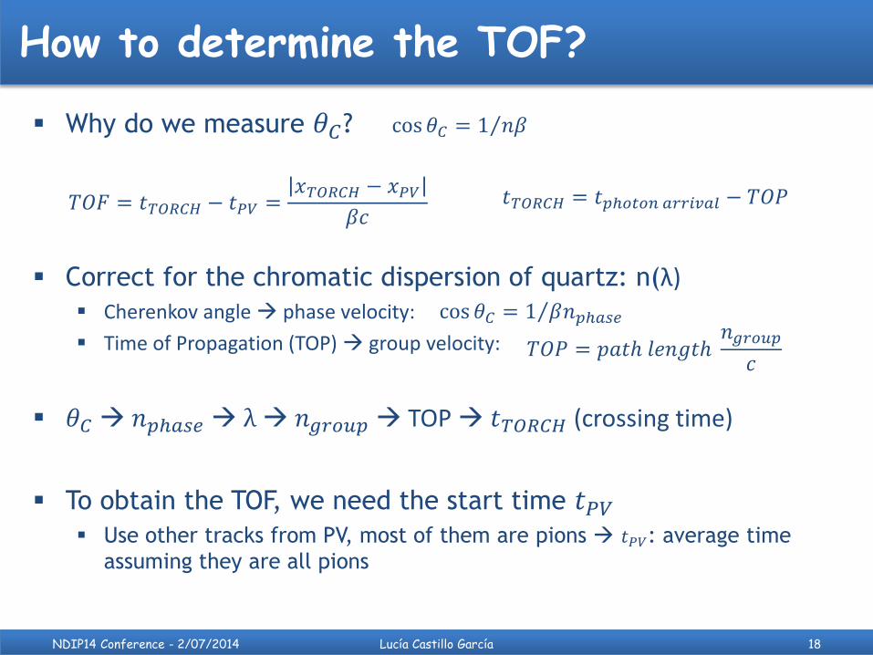
How to determine the TOF?
Why do we measure 𝜃𝐶?
Correct for the chromatic dispersion of quartz: n(λ) Cherenkov angle phase velocity:
Time of Propagation (TOP) group velocity:
𝜃𝐶 𝑛𝑝ℎ𝑎𝑠𝑒 λ 𝑛𝑔𝑟𝑜𝑢𝑝 TOP 𝑡𝑇𝑂𝑅𝐶𝐻 (crossing time)
To obtain the TOF, we need the start time 𝑡𝑃𝑉 Use other tracks from PV, most of them are pions 𝑡𝑃𝑉: average time
assuming they are all pions
NDIP14 Conference - 2/07/2014 Lucía Castillo García 18
𝑡𝑇𝑂𝑅𝐶𝐻 = 𝑡𝑝ℎ𝑜𝑡𝑜𝑛 𝑎𝑟𝑟𝑖𝑣𝑎𝑙 − 𝑇𝑂𝑃
𝑇𝑂𝑃 = 𝑝𝑎𝑡ℎ 𝑙𝑒𝑛𝑔𝑡ℎ 𝑛𝑔𝑟𝑜𝑢𝑝
𝑐
cos 𝜃𝐶 = 1 𝛽𝑛𝑝ℎ𝑎𝑠𝑒
𝑇𝑂𝐹 = 𝑡𝑇𝑂𝑅𝐶𝐻 − 𝑡𝑃𝑉 =𝑥𝑇𝑂𝑅𝐶𝐻 − 𝑥𝑃𝑉
𝛽𝑐
cos 𝜃𝐶 = 1 𝑛𝛽

TORCH detector
NDIP14 Conference - 2/07/2014 Lucía Castillo García 19
Unrealistic to cover with a single quartz plate evolve to modular layout
For LHCb, surface to be instrumented
is ~5x6m² at z=10m
18 identical modules, each 250661cm3 ~300 litres of quartz in total
Reflective lower edge photon detectors
only needed on upper edge
18 11 = 198 units, each with 1024 pads 200k channels in total

Application: LHCb experiment
Motivation for TORCH development is LHCb upgrade
Luminosity: 2 ∙ 1033𝑐𝑚−2𝑠−1
Event read out rate increased to 40𝑀𝐻𝑧
NDIP14 Conference - 2/07/2014 Lucía Castillo García 20
Currently, PID provided by two RICH
detectors with three radiators (Silica
aerogel, 𝐶4𝐹10, 𝐶𝐹4) covering a
momentum range from ~2𝐺𝑒𝑉/𝑐 up to
100𝐺𝑒𝑉/𝑐
PID Upgrade: Silica aerogel will not give a good
performance (low photon yield
<10 detected photons/saturated
track) To be removed and
possibly replaced later by TORCH
[CERN-LHCC-2011-001]

Photon detector:
8x8 channels MCP-PMTs (Burle/Photonis)
XP85012/A1 specifications:
MCP-PMT planacon
8x8 array, 5.9/6.5 mm size/pitch
25 μm pore diameter, chevron configuration (2), 55% open-area ratio
MCP gain up to 10⁶
Large gaps: PC-MCPin: ~ 4.5mm
MCPout-anode: ~ 3.5mm
53 mm x 53 mm active area, 59 mm x 59 mm total area 80% coverage ratio
Total input active surface ratio ≤ 44%
Bialkali photocathode
Rise time 600 ps, pulse width 1.8 ns
HV applied 2.6 kV (1.75 kV across the MCP)
MCP-PMT Planacon tube (Photonis)
NDIP14 Conference - 2/07/2014 Lucía Castillo García 21
Photonis
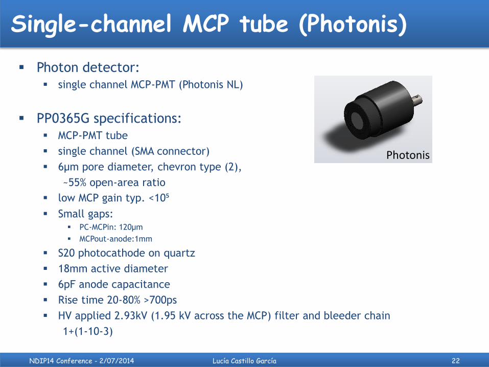
Single-channel MCP tube (Photonis)
Photon detector:
single channel MCP-PMT (Photonis NL)
PP0365G specifications:
MCP-PMT tube
single channel (SMA connector)
6µm pore diameter, chevron type (2),
~55% open-area ratio
low MCP gain typ. <10⁵
Small gaps: PC-MCPin: 120µm
MCPout-anode:1mm
S20 photocathode on quartz
18mm active diameter
6pF anode capacitance
Rise time 20-80% >700ps
HV applied 2.93kV (1.95 kV across the MCP) filter and bleeder chain
1+(1-10-3)
NDIP14 Conference - 2/07/2014 Lucía Castillo García 22
Photonis

Custom MCP device (Photek)
Photon detector:
single channel MCP-PMT225 (Photek Ltd)
PMT225 SN-G specifications:
MCP-PMT tube
single channel (SMA connector)
10µm pore diameter, chevron type (2), ALD coated
MCP gain typ. 10⁶
Small gaps: PC-MCPin: 200µm
S20 photocathode on quartz
25mm active diameter
Rise time 360 ps
HV applied 2.25 kV (1.2 kV across the MCP)
NDIP14 Conference - 2/07/2014 Lucía Castillo García 23

MCP photon detectors tests – Summary
NDIP14 Conference - 2/07/2014 Lucía Castillo García 24
8x8array
Planacon MCP
(Photonis)
Single-channel
MCP (Photonis)
Single-channel MCP
(Photek)
Pore diameter [μm] 25 6 10
PC-MCP/MCP-anode gaps large small small
Photocathode Bialkali on
borosilicate S20 on quartz S20 on quartz
Typical MCP gain 10⁶ 10⁵ 10⁶
Time resolution [ps]
Single-channel
electronics: <40 <40 <30
Multi-channel
electronics: <80
Photonis Photonis Photek

N: number of photoelectrons per pulse
N-photoelectron peak width scales as:
where 𝜎1𝑝ℎ𝑒 is the 1-photoelectron peak width
Experimental setup
Pulsed blue (405nm) laser diode @1KHz (20ps FWHM, sync<3ps)
Monomode fibers
ND filters: single photon regime
Single-channel ORTEC electronics
Light calibration setup: Pulse height spectra (PHS)
Standard Poisson distribution to fit data
Average number of photoelectrons per pulse (µ)
inferred from P(0)
NDIP14 Conference - 2/07/2014 Lucía Castillo García 25
Charge preamplifier
Pulsed blue laser diode
synch<3ps
Fan IN/ OUT
ADC
Shaping amplifier
Gate
scope
Ligth-tight box
ND filters
MCP
Monomode optical fiber
lens
(0.5µs)
surfacetotal
Ae
NNP NN
N
2
!)( Light source
fluctuation
𝜎𝑁𝑝ℎ𝑒 = 𝑁𝜎1𝑝ℎ𝑒 MCP gain fluctuations

Experimental setup
Pulsed blue (405nm) laser diode @1KHz (20ps FWHM, sync<3ps)
Monomode fibers
ND filters: single photon regime
Single-channel ORTEC electronics
Light calibration setup: Pulse height spectrum (PHS)
Standard Poisson distribution to fit data
Average number of photoelectrons per pulse (µ)
inferred from P(0)
Timing setup: Time jitter distribution
Exponentially-modified Gaussian distribution
to fit prompt peak time resolution (σ)
NDIP14 Conference - 2/07/2014 Lucía Castillo García 26
Fast amplifier + CFD
Pulsed blue laser diode
synch<3ps
START
ADC
TAC module
Ligth-tight box
ND filters
MCP
Monomode optical fiber
lens
STOP

Discriminator behaviour
For a given discriminator threshold: The noise induces a jitter signal is detected earlier or later in time
The signal height variation induces a walk: Large signals are detected earlier
Small signals are detected later
Constant Fraction discriminator: Based on zero-crossing techniques
Produce accurate timing information from analog signals of varying heights but the same rise time
Principle: splitting the input signal, attenuating half of it and delaying the other half, then feeding the two halves into a fast comparator with the delayed input inverted
Effect: to trigger a timing signal at a constant fraction of the input amplitude, usually around 20%
NDIP14 Conference - 2/07/2014 Lucía Castillo García 27
- Large amplitudes:
+walk earlier / -walk later
- Smaller amplitudes:
+walk later / -walk earlier
CFD
+ residual walk
- residual walk
t
Amplitude (mV)

Contributions to MCP timing response
Laser effect: Second relaxation pulse clearly seen after ~(150 ± 50)ps on laser timing profile visible on
MCPs time response resulting in a shoulder after the main peak
Back-scattered photoelectrons: Maximum back-scattered time (elastically at 90˚ with MCP input surface):
Maximum back-scattered spatial range (elastically at 45˚ with MCP input surface):
NDIP14 Conference - 2/07/2014 Lucía Castillo García 28
𝑑𝑚𝑎𝑥 𝑡𝑚𝑎𝑥
(𝑡𝑏𝑎𝑐𝑘−𝑠𝑐𝑎𝑡𝑡𝑒𝑟𝑒𝑑) 𝑀𝐴𝑋= 2 × 𝑡𝑡𝑟𝑎𝑛𝑠𝑖𝑡
(𝑑𝑏𝑎𝑐𝑘−𝑠𝑐𝑎𝑡𝑡𝑒𝑟𝑒𝑑) 𝑀𝐴𝑋= 2 ×MCP input gap
PiLas test ticket
60% (FWHM ~ 21ps) optimal

Single-channel timing fitting model
Single-channel MCP investigated at several light intensities and laser
tune setting
Main peak of timing distributions represents the MCP intrinsic time
response fitted with an exponentially-modified Gaussian
distribution
𝑡: time, 𝐴: amplitude, 𝑡𝑐: centroid at maximum height of the unmodified Gaussian, 𝜎𝑔: standard
deviation of the unmodified Gaussian, 𝜏: time constant of exponential decay used to modify the
Gaussian and 𝑒𝑟𝑓 𝑧 =2
𝜋 𝑒−𝑡
2𝑑𝑡
𝑧
0.
Model chosen given the asymmetry in the MCP time response for large values of 𝜇.
Time jitter value defined as the standard deviation 𝝈𝒈 of the Gaussian.
Use to extract the timing resolution for Planacon MCP
NDIP14 Conference - 2/07/2014 Lucía Castillo García 29
𝑓 𝑡, 𝐴, 𝑡𝑐 , 𝜎𝑔, 𝜏 =𝐴
𝜏exp
1
2
𝜎𝑔
𝜏
2
−𝑡 − 𝑡𝑐𝜏
1
2+1
2erf
𝑡 − 𝑡𝑐𝜎𝑔
−𝜎𝑔𝜏
2
[L. Castillo García, LHCb-INT-2013-042]
[I. G. McWilliam, H. C. Bolton, Analytical Chemistry, Vol. 41, No. 13, November (1969) 1755-1762]