mcp3421 weight scale demo board user's...
TRANSCRIPT

2010 Microchip Technology Inc. DS51918A
MCP3421Weight Scale Demo Board
User’s Guide

Note the following details of the code protection feature on Microchip devices:
• Microchip products meet the specification contained in their particular Microchip Data Sheet.
• Microchip believes that its family of products is one of the most secure families of its kind on the market today, when used in the intended manner and under normal conditions.
• There are dishonest and possibly illegal methods used to breach the code protection feature. All of these methods, to our knowledge, require using the Microchip products in a manner outside the operating specifications contained in Microchip’s Data Sheets. Most likely, the person doing so is engaged in theft of intellectual property.
• Microchip is willing to work with the customer who is concerned about the integrity of their code.
• Neither Microchip nor any other semiconductor manufacturer can guarantee the security of their code. Code protection does not mean that we are guaranteeing the product as “unbreakable.”
Code protection is constantly evolving. We at Microchip are committed to continuously improving the code protection features of ourproducts. Attempts to break Microchip’s code protection feature may be a violation of the Digital Millennium Copyright Act. If such actsallow unauthorized access to your software or other copyrighted work, you may have a right to sue for relief under that Act.
Information contained in this publication regarding deviceapplications and the like is provided only for your convenienceand may be superseded by updates. It is your responsibility toensure that your application meets with your specifications.MICROCHIP MAKES NO REPRESENTATIONS ORWARRANTIES OF ANY KIND WHETHER EXPRESS ORIMPLIED, WRITTEN OR ORAL, STATUTORY OROTHERWISE, RELATED TO THE INFORMATION,INCLUDING BUT NOT LIMITED TO ITS CONDITION,QUALITY, PERFORMANCE, MERCHANTABILITY ORFITNESS FOR PURPOSE. Microchip disclaims all liabilityarising from this information and its use. Use of Microchipdevices in life support and/or safety applications is entirely atthe buyer’s risk, and the buyer agrees to defend, indemnify andhold harmless Microchip from any and all damages, claims,suits, or expenses resulting from such use. No licenses areconveyed, implicitly or otherwise, under any Microchipintellectual property rights.
DS51918A-page 2
Trademarks
The Microchip name and logo, the Microchip logo, dsPIC, KEELOQ, KEELOQ logo, MPLAB, PIC, PICmicro, PICSTART, PIC32 logo, rfPIC and UNI/O are registered trademarks of Microchip Technology Incorporated in the U.S.A. and other countries.
FilterLab, Hampshire, HI-TECH C, Linear Active Thermistor, MXDEV, MXLAB, SEEVAL and The Embedded Control Solutions Company are registered trademarks of Microchip Technology Incorporated in the U.S.A.
Analog-for-the-Digital Age, Application Maestro, CodeGuard, dsPICDEM, dsPICDEM.net, dsPICworks, dsSPEAK, ECAN, ECONOMONITOR, FanSense, HI-TIDE, In-Circuit Serial Programming, ICSP, Mindi, MiWi, MPASM, MPLAB Certified logo, MPLIB, MPLINK, mTouch, Octopus, Omniscient Code Generation, PICC, PICC-18, PICDEM, PICDEM.net, PICkit, PICtail, REAL ICE, rfLAB, Select Mode, Total Endurance, TSHARC, UniWinDriver, WiperLock and ZENA are trademarks of Microchip Technology Incorporated in the U.S.A. and other countries.
SQTP is a service mark of Microchip Technology Incorporated in the U.S.A.
All other trademarks mentioned herein are property of their respective companies.
© 2010, Microchip Technology Incorporated, Printed in the U.S.A., All Rights Reserved.
Printed on recycled paper.
ISBN: 978-1-60932-687-6
Microchip received ISO/TS-16949:2002 certification for its worldwide
2010 Microchip Technology Inc.
headquarters, design and wafer fabrication facilities in Chandler and Tempe, Arizona; Gresham, Oregon and design centers in California and India. The Company’s quality system processes and procedures are for its PIC® MCUs and dsPIC® DSCs, KEELOQ® code hopping devices, Serial EEPROMs, microperipherals, nonvolatile memory and analog products. In addition, Microchip’s quality system for the design and manufacture of development systems is ISO 9001:2000 certified.
MCP3421 WEIGHT SCALEDEMO BOARD USER’S GUIDE
Table of Contents
Preface ........................................................................................................................... 5
Chapter 1. Product Overview1.1 Overview ........................................................................................................ 91.2 Analog Input Configuration Options ............................................................. 101.3 Load Cell ...................................................................................................... 111.4 Universal Serial Bus (USB) and PIC18F4550 Microcontroller ..................... 121.5 What the MCP3421 Weight Scale Kit Contains ........................................... 12
Chapter 2. Installation and Operation2.1 MCP3421 Configuration Bit Settings and Data Acquisition .......................... 132.2 USB Communication .................................................................................... 13
Chapter 3. Weight Scale PC Software Tool3.1 Software Installation ..................................................................................... 153.2 Software Overview ....................................................................................... 153.3 Weight Scale Calibration .............................................................................. 16
Appendix A. Schematics and LayoutsA.1 Introduction .................................................................................................. 17A.2 Board – Schematic ....................................................................................... 18A.3 Board – Top Copper and Pads .................................................................... 19A.4 Board – Top Pads and Silk .......................................................................... 20A.5 Board – Top Copper, Pads and Silk ............................................................ 21A.6 Board – Bottom Copper and Pads ............................................................... 22
Appendix B. Bill of Materials
Worldwide Sales and Service .................................................................................... 26
2010 Microchip Technology Inc. DS51918A-page 3

MCP3421 Weight Scale Demo Board User’s Guide
NOTES:
DS51918A-page 4 2010 Microchip Technology Inc.
MCP3421 WEIGHT SCALEDEMO BOARD USER’S GUIDE
Preface
INTRODUCTION
This chapter contains general information that will be useful to know before using the MCP3421 Weight Scale Demo Board. Items discussed in this chapter include:
• Document Layout
• Conventions Used in this Guide
• Recommended Reading
• The Microchip Web Site
• Customer Support
• Document Revision History
DOCUMENT LAYOUT
This document describes how to use the MCP3421 Weight Scale Demo Board as a development tool to emulate and debug firmware on a target board. The manual layout is as follows:
• Chapter 1. “Product Overview” – Provides important information about the MCP3421 Weight Scale Demo Board hardware.
• Chapter 2. “Installation and Operation” – Describes the MCP3421 Weight Scale Demo Board firmware.
• Chapter 3. “Weight Scale PC Software Tool” – Provides detailed information about the board’s PC software tool.
• Appendix A. “Schematics and Layouts” – Shows the schematic and board layouts for the MCP3421 Weight Scale Demo Board.
• Appendix B. “Bill of Materials” – Lists the parts used to build the MCP3421 Weight Scale Demo Board.
NOTICE TO CUSTOMERS
All documentation becomes dated, and this manual is no exception. Microchip tools and documentation are constantly evolving to meet customer needs, so some actual dialogs and/or tool descriptions may differ from those in this document. Please refer to our web site (www.microchip.com) to obtain the latest documentation available.
Documents are identified with a “DS” number. This number is located on the bottom of each page, in front of the page number. The numbering convention for the DS number is “DSXXXXXA”, where “XXXXX” is the document number and “A” is the revision level of the document.
For the most up-to-date information on development tools, see the MPLAB® IDE online help. Select the Help menu, and then Topics to open a list of available on-line help files.
2010 Microchip Technology Inc. DS51918A-page 5

MCP3421 Weight Scale Demo Board User’s Guide
CONVENTIONS USED IN THIS GUIDE
This manual uses the following documentation conventions:
DOCUMENTATION CONVENTIONS
Description Represents Examples
Arial font:
Italic characters Referenced books MPLAB® IDE User’s Guide
Emphasized text ...is the only compiler...
Initial caps A window the Output window
A dialog the Settings dialog
A menu selection select Enable Programmer
Quotes A field name in a window or dialog
“Save project before build”
Underlined, italic text with right angle bracket
A menu path File>Save
Bold characters A dialog button Click OK
A tab Click the Power tab
N‘Rnnnn A number in verilog format, where N is the total number of digits, R is the radix and n is a digit.
4‘b0010, 2‘hF1
Text in angle brackets < > A key on the keyboard Press <Enter>, <F1>
Courier New font:
Plain Courier New Sample source code #define START
Filenames autoexec.bat
File paths c:\mcc18\h
Keywords _asm, _endasm, static
Command-line options -Opa+, -Opa-
Bit values 0, 1
Constants 0xFF, ‘A’
Italic Courier New A variable argument file.o, where file can be any valid filename
Square brackets [ ] Optional arguments mcc18 [options] file [options]
Curly brackets and pipe character: { | }
Choice of mutually exclusive arguments; an OR selection
errorlevel {0|1}
Ellipses... Replaces repeated text var_name [, var_name...]
Represents code supplied by user
void main (void){ ...}
DS51918A-page 6 2010 Microchip Technology Inc.

Preface
RECOMMENDED READING
This user’s guide describes how to use MCP3421 Weight Scale Demo Board. Other useful documents are listed below. The following Microchip documents are available and recommended as supplemental reference resources:
• MCP3421 Data Sheet – 18-Bit Analog-to-Digital Converter with I2C™ Interface and On-Board Reference (DS22003)
• MCP3422/3/4 Data Sheet – 18-Bit, Multi-Channel ΔΣ Analog-to-Digital Converter with I2C™ Interface and On-Board Reference (DS22088)
• MCP6V07 Data Sheet – 300 µA, Auto-Zeroed Op Amps (DS22093)
• PIC18F4550 Data Sheet – 28/40/44-Pin, High-Performance, Enhanced Flash, USB Microcontrollers with nanoWatt Technology (DS39632)
• AN1030 – Weigh Scale Applications for the MCP3551 (DS01030)
THE MICROCHIP WEB SITE
Microchip provides online support via our web site at www.microchip.com. This web site is used as a means to make files and information easily available to customers. Accessible by using your favorite Internet browser, the web site contains the following information:
• Product Support – Data sheets and errata, application notes and sample programs, design resources, user’s guides and hardware support documents, latest software releases and archived software
• General Technical Support – Frequently Asked Questions (FAQs), technical support requests, online discussion groups, Microchip consultant program member listing
• Business of Microchip – Product selector and ordering guides, latest Microchip press releases, listing of seminars and events, listings of Microchip sales offices, distributors and factory representatives
CUSTOMER SUPPORT
Users of Microchip products can receive assistance through several channels:
• Distributor or Representative
• Local Sales Office
• Field Application Engineer (FAE)
• Technical Support
Customers should contact their distributor, representative or field application engineer (FAE) for support. Local sales offices are also available to help customers. A listing of sales offices and locations is included in the back of this document.
Technical support is available through the web site at: http://support.microchip.com.
DOCUMENT REVISION HISTORY
Revision A (November 2010)
• Initial Release of this Document.
2010 Microchip Technology Inc. DS51918A-page 7
MCP3421 Weight Scale Demo Board User’s Guide
NOTES:
DS51918A-page 8 2010 Microchip Technology Inc.

MCP3421 WEIGHT SCALEDEMO BOARD USER’S GUIDE
Chapter 1. Product Overview
1.1 OVERVIEW
The MCP3421 Weight Scale Demo Board works with the LabVIEW™ Graphical User Interface (GUI) PC Software. This demo board demonstrates how to use the MCP3421 18-bit Delta-Sigma ADC for weight scale applications. It uses the PIC18F4550 micro-controller for data processing and USB communication with PC. This board also dem-onstrates the changes in the system performance by adjusting the parameters of the sensor signal conditioning circuits using the MCP6V07 auto-zeroed op amp.
1.1.1 Feature Highlights
• The LCD displays the user’s selected option and the ADC output code or the calculated results.
• The user can select the signal averaging factor (1 or 4) by pressing the S3 button. The selected option is displayed on the LCD.
• System performance analysis using PC GUI: the interface allows various interactive post signal processing, such as standard deviations and histogram.
• Hardware PCB design examples: this demo board utilizes a robust grounding method of analog circuits in PCB design. It also demonstrates how to split analog and digital ground planes.
• Signal conditioning examples using MCP6V07: the low-noise op amp is used to boost input signal levels.
• 2 Kg load cell with 1 mV/V sensitivity.
FIGURE 1-1: MCP3421 Weight Scale Demo Board.
2010 Microchip Technology Inc. DS51918A-page 9
MCP3421 Weight Scale Demo Board User’s Guide
1.2 ANALOG INPUT CONFIGURATION OPTIONS
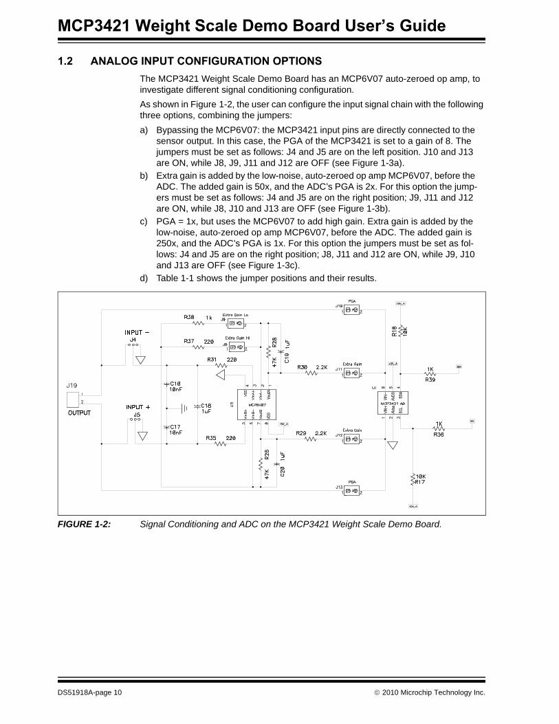
The MCP3421 Weight Scale Demo Board has an MCP6V07 auto-zeroed op amp, to investigate different signal conditioning configuration.
As shown in Figure 1-2, the user can configure the input signal chain with the following three options, combining the jumpers:
a) Bypassing the MCP6V07: the MCP3421 input pins are directly connected to the sensor output. In this case, the PGA of the MCP3421 is set to a gain of 8. The jumpers must be set as follows: J4 and J5 are on the left position. J10 and J13 are ON, while J8, J9, J11 and J12 are OFF (see Figure 1-3a).
b) Extra gain is added by the low-noise, auto-zeroed op amp MCP6V07, before the ADC. The added gain is 50x, and the ADC’s PGA is 2x. For this option the jump-ers must be set as follows: J4 and J5 are on the right position; J9, J11 and J12 are ON, while J8, J10 and J13 are OFF (see Figure 1-3b).
c) PGA = 1x, but uses the MCP6V07 to add high gain. Extra gain is added by the low-noise, auto-zeroed op amp MCP6V07, before the ADC. The added gain is 250x, and the ADC’s PGA is 1x. For this option the jumpers must be set as fol-lows: J4 and J5 are on the right position; J8, J11 and J12 are ON, while J9, J10 and J13 are OFF (see Figure 1-3c).
d) Table 1-1 shows the jumper positions and their results.
FIGURE 1-2: Signal Conditioning and ADC on the MCP3421 Weight Scale Demo Board.
DS51918A-page 10 2010 Microchip Technology Inc.
Product Overview
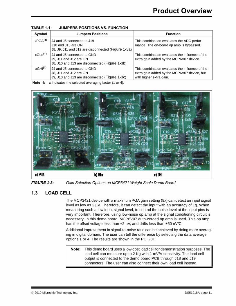
FIGURE 1-3: Gain Selection Options on MCP3421 Weight Scale Demo Board.
1.3 LOAD CELL
The MCP3421 device with a maximum PGA gain setting (8x) can detect an input signal level as low as 2 µV. Therefore, it can detect the input with an accuracy of 1g. When measuring such a low input signal level, to control the noise level at the input pins is very important. Therefore, using low-noise op amp at the signal conditioning circuit is necessary. In this demo board, MCP6V07 auto-zeroed op amp is used. This op amp has the offset voltage less than ±2 µV, and drifts less than ±50 nV/C.
Additional improvement in signal-to-noise ratio can be achieved by doing more averag-ing in digital domain. The user can tell the difference by selecting the data average options 1 or 4. The results are shown in the PC GUI.
TABLE 1-1: JUMPERS POSITIONS VS. FUNCTION
Symbol Jumpers Positions Function
xPGA(1) J4 and J5 connected to J19J10 and J13 are ONJ8, J9, J11 and J12 are disconnected (Figure 1-3a)
This combination evaluates the ADC perfor-mance. The on-board op amp is bypassed.
xGLo(1) J4 and J5 connected to GNDJ9, J11 and J12 are ONJ8, J10 and J13 are disconnected (Figure 1-3b)
This combination evaluates the influence of the extra gain added by the MCP6V07 device.
xGHi(1) J4 and J5 connected to GNDJ8, J11 and J12 are ONJ9, J10 and J13 are disconnected (Figure 1-3c)
This combination evaluates the influence of the extra gain added by the MCP6V07 device, but with higher extra gain.
Note 1: x indicates the selected averaging factor (1 or 4).
Note: This demo board uses a low-cost load cell for demonstration purposes. The load cell can measure up to 2 Kg with 1 mV/V sensitivity. The load cell output is connected to the demo board PCB through J18 and J19 connectors. The user can also connect their own load cell instead.
2010 Microchip Technology Inc. DS51918A-page 11

MCP3421 Weight Scale Demo Board User’s Guide
1.4 UNIVERSAL SERIAL BUS (USB) AND PIC18F4550 MICROCONTROLLER
The MCP3421 Weight Scale Demo Board has a USB connector to communicate with the PC GUI. The PC GUI allows various user options, such as calibrations and perfor-mance evaluation of the system.
The USB communication with the PC is done by the on-board microcontroller. PIC18F4550 is also communicating with the ADC, and controls the LCD.
The four button switches on the board have the following functions:
• S5 is the Reset pin
• S2 is used to change the LCD indication from “Weight” to “ADC code”, “ADC out-put”, or “Calibration”
• S3 is used in parallel with the configuration of the signal conditioning chain. By pressing this button, the LCD indication will change from 1PGA to 1GLo, 1GHi, 4PGA, 4GLo or 4GHi. PGA means that the ADCs PGA only is used at highest gain. GLo means that the external op amp is being used with low gain, GHi means that external op amp is used with high gain. The 1 and 4 before the letters indicate the numbers of averages – no averaging, or averaging on four samples
• S4 is doing the zero calibration. By pressing this button, the “Weight” indication will go to a value closer to 0g.
1.5 WHAT THE MCP3421 WEIGHT SCALE KIT CONTAINS
The MCP3421 Weight Scale Demo Board kit includes:
• MCP3421 Weight Scale Demo Board, 102-00250
• Important Information Sheet
DS51918A-page 12 2010 Microchip Technology Inc.
MCP3421 WEIGHT SCALEDEMO BOARD USER’S GUIDE
Chapter 2. Installation and Operation
2.1 MCP3421 CONFIGURATION BIT SETTINGS AND DATA ACQUISITION
The communication with the ADC is done through I2C, but the I2C peripheral port of the MCU is not being used. Instead, two pins (RA4, RA5) are being controlled from the firm-ware.
The MCU is changing the setup of the ADC each time S3 is pressed, to change the PGA gain: 8x for PGA, 2x for GLo and 1x for GHi. The ADC always operates in 18-bit mode.
The data received from the MCP3421 device is scaled to a value expressed in grams by the compute() function, in order to be displayed on the LCD.
There are two calibration steps: offset subtraction and gain scaling. The two values, the offset and the gain constants, are stored in EEPROM during the calibration, and read out at Reset, or when the S3 is pressed.
2.2 USB COMMUNICATION
The Microchip USB Firmware Framework is a software library developed by Microchip Technology Inc., that can be used to create new USB applications. It can be considered as a reference design project, containing the necessary firmware code for USB operation, also providing a placeholder for user’s code. The whole code project is contained within one single root project directory, with many subdirectories for source code organization.
Microchip provides a general purpose Windows® driver which can be used with Win-dows applications, to interface with a custom class USB device. The driver will not be used in all USB applications, one of the exceptions being the USB HID class devices, which would normally use built-in HID class drivers distributed with the OS.
For USB applications that do not easily fit within the constraints of these other device class options, Microchip’s general purpose driver may be used. Windows applications can access the USB devices either by directly interfacing with the driver (mchpusb.sys), or indirectly use the driver through a pre-compiled library.
A custom class Windows application using the Microchip general purpose USB driver may interface directly with the driver (mchpusb.sys). By doing so, it requires more effort and more learning time than using a pre-compiled library that exposes a simple to use API, including basic functions like open(), read(), write() and close().
The MPUSBAPI.DLL file is a library which provides a number of functions, including the basic ones needed for reading and writing to an USB device. A list of the functions available and the calling conventions for those functions is currently documented in the form of in-line comments in the source code for the DLL file. The DLL is compiled using Borland® C++ Builder™ 6 development environment, and the source code is provided in the <System Driver>:\MCHPFSUSB\Pc\Mpusbapi\Dll\Borland_C\Source directory.
2010 Microchip Technology Inc. DS51918A-page 13
MCP3421 Weight Scale Demo Board User’s Guide
A load time linking and a run time linking example, showing how to use the DLL, are included in the System Driver:\MCHPFSUSB\Pc\Mpusbapi\Example Applications directory.
The MCP3421 Weight Scale Demo Board firmware is mainly based on the USB stack example: “Device – MCHPUSB – Generic Driver Demo”. Most of the firmware changes of the MPLAB MCP3421 Weight Scale Demo Board project are done in the user v7 eeprom.c file. This project is downloadable from Microchip’s MCP3421 product page web site: http://www.microchip.com/wwwproducts/Devices.aspx?dDoc-Name=en520011.
The input offset error voltage is computed when S4 is being pressed. The gain constant is computed by the PC software and transmitted to the MCU via USB on the OUT-Packet._byte[2] to OUTPacket._byte[7].
The weight scale is sending to the PC software the following values: weight, ADC code, ADC output, zero calibration and gain calibration, represented by six characters using INPacket._byte[0] to INPacket._byte[31].
Note: For running this project, the USB Microchip Stack must be installed on the user’s machine.
DS51918A-page 14 2010 Microchip Technology Inc.

MCP3421 WEIGHT SCALEDEMO BOARD USER’S GUIDE
Chapter 3. Weight Scale PC Software Tool
3.1 SOFTWARE INSTALLATION
The Weight Scale PC software is an executable file that does not require installation. But, to enable running the software, the user must first install two additional programs, in the following order:
- NI LabVIEW Run-Time Engine
- NI-VISA Run-Time Engine
These programs can be downloaded from www.ni.com.
3.2 SOFTWARE OVERVIEW
The MCP3421 Weight Scale Demo Board includes a PC graphical user interface (GUI), that can be used to evaluate the weight scale accuracy and weight scale calibration.
This board is communicating with the software via USB port.
The following figure shows a sample of the software’s GUI in Measurement mode:
FIGURE 3-1: MCP3421 Weight Scale Demo Board Software – Measurement Mode.
The user can control the size of the X axis by writing the desired figure in buffer length. Several series of statistical analysis are performed on this buffer, the most important being displayed on the screen, under the Measurement Standard Deviation. This deviation is measured in grams and represents the RMS noise value of the weight scale. The actual accuracy of the weight scale can be defined in many ways, but most commonly it is 10 times the standard deviation.
2010 Microchip Technology Inc. DS51918A-page 15
MCP3421 Weight Scale Demo Board User’s Guide
3.3 WEIGHT SCALE CALIBRATION
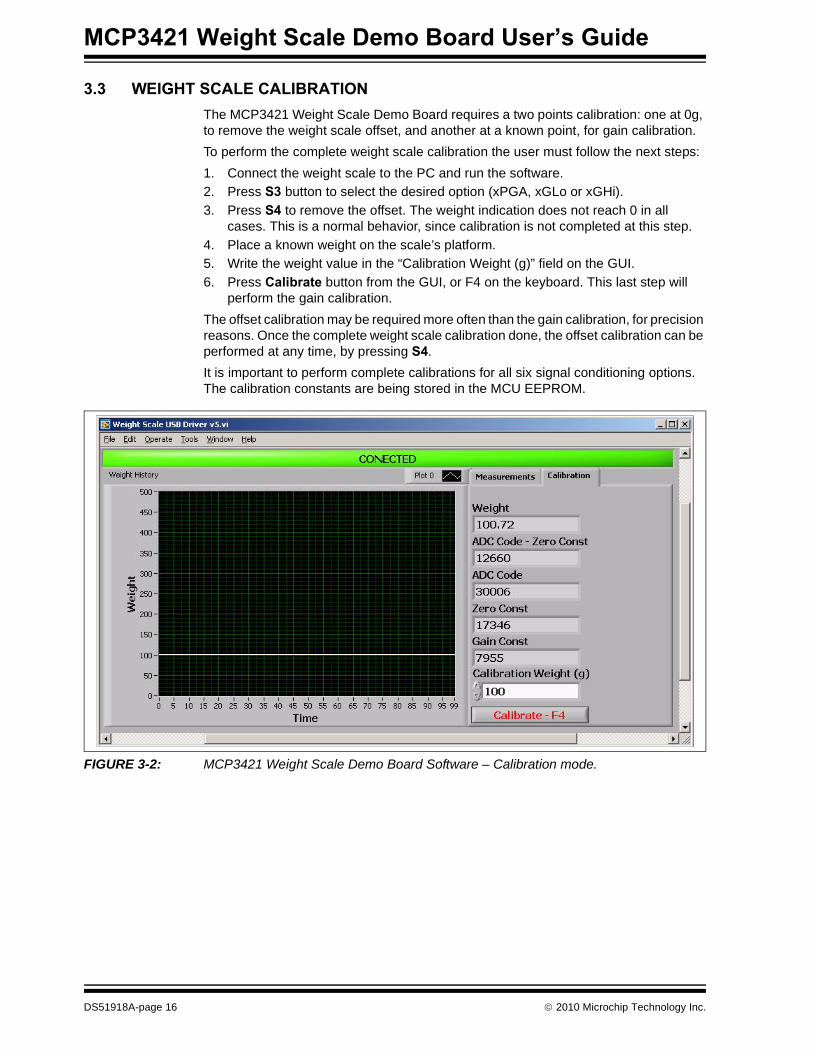
The MCP3421 Weight Scale Demo Board requires a two points calibration: one at 0g, to remove the weight scale offset, and another at a known point, for gain calibration.
To perform the complete weight scale calibration the user must follow the next steps:
1. Connect the weight scale to the PC and run the software.
2. Press S3 button to select the desired option (xPGA, xGLo or xGHi).
3. Press S4 to remove the offset. The weight indication does not reach 0 in all cases. This is a normal behavior, since calibration is not completed at this step.
4. Place a known weight on the scale’s platform.
5. Write the weight value in the “Calibration Weight (g)” field on the GUI.
6. Press Calibrate button from the GUI, or F4 on the keyboard. This last step will perform the gain calibration.
The offset calibration may be required more often than the gain calibration, for precision reasons. Once the complete weight scale calibration done, the offset calibration can be performed at any time, by pressing S4.
It is important to perform complete calibrations for all six signal conditioning options. The calibration constants are being stored in the MCU EEPROM.
FIGURE 3-2: MCP3421 Weight Scale Demo Board Software – Calibration mode.
DS51918A-page 16 2010 Microchip Technology Inc.

MCP3421 WEIGHT SCALEDEMO BOARD USER’S GUIDE
Appendix A. Schematics and Layouts
A.1 INTRODUCTION
This appendix contains the following schematics and layouts for the MCP3421 Weight Scale Demo Board:
• Board – Schematic
• Board – Top Copper and Pads
• Board – Top Pads and Silk
• Board – Top Copper, Pads and Silk
• Board – Bottom Copper and Pads
2010 Microchip Technology Inc. DS51918A-page 17
MCP3421 Weight Scale Demo Board User’s Guide
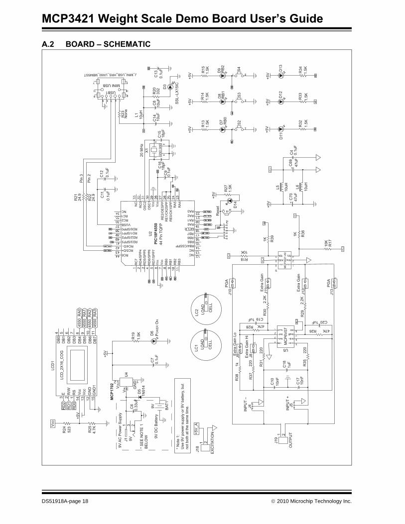
A.2 BOARD – SCHEMATIC
R24 523
+5V
R25
4.7K
VD
DLC
D1
LCD
_2X
16_C
OG
+5V
MCP1702
RD
2R
D1
RD
0
DB
0D
B1
DB
2D
B3
DB
4D
B5
DB
6D
B7
E R/W
RS
VE
E
Vcc
GN
DG
ND
1
3 2 1 14 13 12 15111098754 6
4550
_RA
045
50_R
A1
4550
_RA
245
50_R
A3
VO
UT
U4
VIN G
ND
D5
1N91
42
3
1
C7
0.1U
FP
OW
ER O
N
D6
R19
1.5K
BAT
1
9V9V
DC
Bat
tery
* S
EE
NO
TE 1
BE
LOW
C6
0.33
uF231
9VJ19V
AC
Pow
er S
uppl
y
* N
ote
1:U
se 9
V p
ower
sup
ply
or 9
V b
atte
ry, b
utno
t bot
h at
the
sam
e tim
e.
J18
1 2
+5V
_A
EX
CIT
ATIO
N
LC1
LOA
D
CE
LL
LC2
LOA
D
CE
LL
INP
UT
–J4
J19
1 2
OU
TPU
TIN
PU
T +
J5
R38
1kE
xtra
Gai
n Lo
J9
R37
220
J8Ext
ra G
ain
Hi
R31
220
PG
AJ1
0
C10
10nF
C18
1uF
C17
10nF
R35
220
MC
P6V
07
R30
2.2K
Ext
ra G
ain
J11 Ext
ra G
ain
J12
PG
AJ1
3
1K R39
1K R36
10K
R17
+5V
C70
47uF
L5 10uH
10uHL6
C69
47uF
D11
R27
1.5K
+5V
Res
et
PIC18F4550
U2
44 P
in T
QFP
20 M
Hz
X1
D12
D13
R32
R33
R34
1.5K
1.5K
1.5K
+5V
+5V
+5V
R21
24.9
R22
24.9
Pin
3
Pin
2
C4
0.1u
F
D14
C11
0.1u
F
C12
0.1u
F
U5
R29
2.2K
47KR28R26 47K
C191uF C201uF
MC
P34
21 A
0
R18
10K
+5V
+5V
+5V
D7
D8
D9
RB
0R
B1
RB
2
S2
S3
S4
1.5K
1.5K
1.5K
R13
R14
R15
SS
L–LX
15IC
D3
R20
332
C8
C14
10uF
10uF
C13
0.1u
F
L1 10uH
Non
eR
23
C15
18pF
GN
DG
ND
C16
18pF
C9
0.1u
F
J_MINI_USB_HRS_UX60_MBM5ST
USB1
MINI USB
NCNCRB4/CSSPP
RB6RB7MCLR
RA1RA2
RB5
RA3
RA0
RC6RC5/D+RC4/D–
RD3/SPP3RD2/SPP2RD1/SPP1RD0/SPP0
VUSBRC2RC1NC
RC
7R
D4/
SP
P4
RD
5/S
PP
5R
D6/
SP
P6
RD
7/S
PP
7V
SS
VD
D
RB
0R
B1
RB
2R
B3
NC
RC
0O
SC
2O
SC
1
VD
D
VS
S
RE
2/O
ES
PP
RE
1/C
K2S
PP
RE
0/C
K1S
PP
RA
5R
A4
DS51918A-page 18 2010 Microchip Technology Inc.

Schematics and Layouts
A.3 BOARD – TOP COPPER AND PADS
2010 Microchip Technology Inc. DS51918A-page 19

MCP3421 Weight Scale Demo Board User’s Guide
A.4 BOARD – TOP PADS AND SILK
BO
AR
D E
DG
E
DS51918A-page 20 2010 Microchip Technology Inc.
Schematics and Layouts
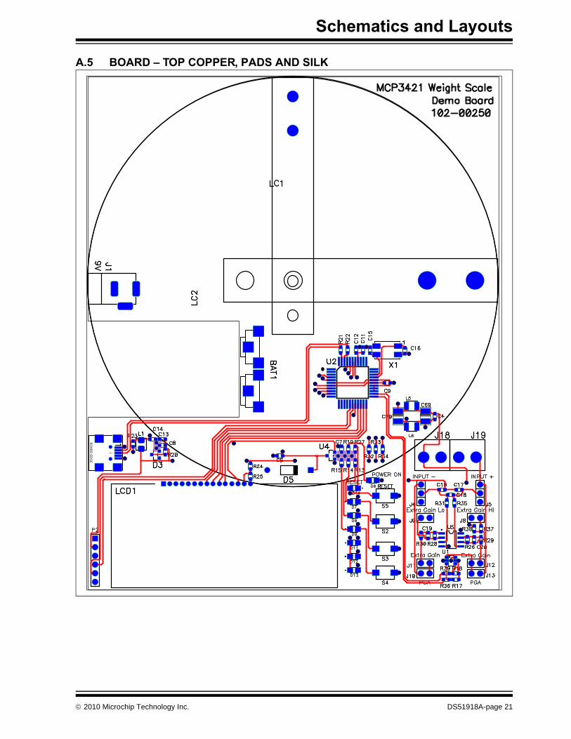
A.5 BOARD – TOP COPPER, PADS AND SILK
BO
AR
D E
DG
E
2010 Microchip Technology Inc. DS51918A-page 21

MCP3421 Weight Scale Demo Board User’s Guide
A.6 BOARD – BOTTOM COPPER AND PADS
DS51918A-page 22 2010 Microchip Technology Inc.

MCP3421 WEIGHT SCALEDEMO BOARD USER’S GUIDE
Appendix B. Bill of Materials
TABLE B-1: BILL OF MATERIALS (BOM)
Qty Reference Description Manufacturer Part Number
6 C4, C7, C9, C11, C12, C13
CAP X2Y CER .1UF X7R 6.3V 0603 Johanson Dielectrics Inc 6R3X14W104MV4T
1 C6 CAP .33UF 6.3V CERAMIC X5R 0603
Panasonic® – ECG ECJ-1VB0J334K
2 C8, C14 CAP CER 10UF 6.3V X5R 0603 Murata Manufacturing Co., Ltd.
GRM188R60J106ME47D
2 C10, C17 CAP CER 10000PF 50V 10% X7R 0603
Murata Manufacturing Co., Ltd.
GRM188R71H103KA01D
2 C15, C16 CAP CER 18PF 50V 5% C0G 0603 Murata Manufacturing Co., Ltd.
GRM1885C1H180JA01D
3 C18, C19, C20
CAP CER 1.0UF 6.3V 10% X5R 0603 Murata Manufacturing Co., Ltd.
GRM188R60J105KA01D
2 C69, C70 CAP TANTALUM 47UF 6.3V 10% SMD
Kemet B45196H1476K209
1 D3 DO NOT POPULATE — —
1 D5 DIODE SS HI COND100V 200MA DO-35
Fairchild Semiconductor Inc.
1N914BTR
4 D6, D7, D8, D9, D11, D12, D13, D14,
LED GREEN CLEAR THIN 0805 SMD
Lite-On®, Inc. LTST-C171GKT
1 J1 CONN POWERJACK MINI .08" R/A T/H
Switchcraft®, Inc. RAPC722X
2 J4, J5 CONN HEADER VERT 2POS .100 TIN
Tyco Electronics 3-644695-3
6 J8, J9, J10, J11, J12, J13
CONN HEADER VERT 2POS .100 TIN
Tyco Electronics 3-644695-2
2 J18, J19 CONN TERM BLOCK 2.54MM 2POS Phoenix Contact 1725656
2 L5, L6 INDUCTOR 10UH 450MA 1210 Murata Manufacturing Co., Ltd.
LQH32CN100K53L
1 LC1 DO NOT POPULATE — —
1 LC2 Load cell AMA–2kg Xiamen Kuanyi Electronic Technology Co., Ltd.
AMA-2
1 LCD1 16X2 LCD Character Display Fema Electronics Corporation
CG1626-SGR1
1 P2 6way pins MCU programming Tyco Electronics 3-644456-6
1 PCB RoHS Compliant Bare PCB, MCP3421 Weight Scale Demo Board
— 104-00250
Note 1: The components listed in this Bill of Materials are representative of the PCB assembly. The released BOM used in manufacturing uses all RoHS-compliant components.
2010 Microchip Technology Inc. DS51918A-page 23

MCP3421 Weight Scale Demo Board User’s Guide
8 R13, R14, R15, R19, R27, R32, R33, R34
RES 1.50K OHM 1/10W 1% 0603 SMD
Yageo Corporation RC0603FR-071K5L
2 R17, R18 RES 10.0K OHM 1/10W 1% 0603 SMD
Panasonic – ECG ERJ-3EKF1002V
1 R20 RES 332 OHM 1/10W 1% 0603 SMD Panasonic – ECG ERJ-3EKF3320V
2 R21, R22 RES 24.9 OHM 1/10W 1% 0603 SMD Panasonic – ECG ERJ-3EKF24R9V
1 R23 DO NOT POPULATE — —
1 R24 RES 523 OHM 1/10W 1% 0603 SMD Panasonic – ECG ERJ-3EKF5230V
1 R25 RES 4.70K OHM 1/10W 1% 0603 SMD
Panasonic – ECG ERJ-3EKF4701V
2 R26, R28 RES 47.0K OHM 1/10W 1% 0603 SMD
Panasonic – ECG ERJ-3EKF4702V
2 R29, R30 RES 2.20K OHM 1/10W 1% 0603 SMD
Panasonic – ECG ERJ-3EKF2201V
3 R31, R35, R37
RES 220 OHM 1/10W 1% 0603 SMD Panasonic – ECG ERJ-3EKF2200V
3 R36, R38, R39
RES 1.00K OHM 1/10W 1% 0603 SMD
Panasonic – ECG ERJ-3EKF1001V
4 S2, S3, S4, S5
SWITCH LT TOUCH 6X3.5 100GF SMD
Panasonic – ECG EVQ-PJS04K
1 U1 MCP3421 SOT-23_6L A0 Microchip Technology Inc.
MCP3421A0T-E/CH
1 U2 PIC18F4550 TQFP44 Microchip Technology Inc.
PIC18F4550-I/PT
1 U4 MCP1702 SOT23A 5V CMOS low dropout positive voltage regulator
Microchip Technology Inc.
MCP1701T-5002I/CB
1 U5 MCP6V02 SOIC8 Linear High Preci-sion Op Amps-Auto Zero
Microchip Technology Inc.
MCP6V07-E/SN
1 USB1 CONN RECEPT MINI USB2.0 5POS Hirose Electric Co., Ltd. UX60-MB-5ST
1 X1 CRYSTAL 20MHZ METAL CASE SMD
Connor-Winfield XM-1-20.0000
TABLE B-1: BILL OF MATERIALS (BOM) (CONTINUED)
Qty Reference Description Manufacturer Part Number
Note 1: The components listed in this Bill of Materials are representative of the PCB assembly. The released BOM used in manufacturing uses all RoHS-compliant components.
DS51918A-page 24 2010 Microchip Technology Inc.

2010 Microchip Technology Inc. DS51918A-page 25
MCP3421 Weight Scale Demo Board User’s Guide
NOTES:

DS51918A-page 26 2010 Microchip Technology Inc.
AMERICASCorporate Office2355 West Chandler Blvd.Chandler, AZ 85224-6199Tel: 480-792-7200 Fax: 480-792-7277Technical Support: http://support.microchip.comWeb Address: www.microchip.com
AtlantaDuluth, GA Tel: 678-957-9614 Fax: 678-957-1455
BostonWestborough, MA Tel: 774-760-0087 Fax: 774-760-0088
ChicagoItasca, IL Tel: 630-285-0071 Fax: 630-285-0075
ClevelandIndependence, OH Tel: 216-447-0464 Fax: 216-447-0643
DallasAddison, TX Tel: 972-818-7423 Fax: 972-818-2924
DetroitFarmington Hills, MI Tel: 248-538-2250Fax: 248-538-2260
KokomoKokomo, IN Tel: 765-864-8360Fax: 765-864-8387
Los AngelesMission Viejo, CA Tel: 949-462-9523 Fax: 949-462-9608
Santa ClaraSanta Clara, CA Tel: 408-961-6444Fax: 408-961-6445
TorontoMississauga, Ontario, CanadaTel: 905-673-0699 Fax: 905-673-6509
ASIA/PACIFICAsia Pacific OfficeSuites 3707-14, 37th FloorTower 6, The GatewayHarbour City, KowloonHong KongTel: 852-2401-1200Fax: 852-2401-3431
Australia - SydneyTel: 61-2-9868-6733Fax: 61-2-9868-6755
China - BeijingTel: 86-10-8528-2100 Fax: 86-10-8528-2104
China - ChengduTel: 86-28-8665-5511Fax: 86-28-8665-7889
China - ChongqingTel: 86-23-8980-9588Fax: 86-23-8980-9500
China - Hong Kong SARTel: 852-2401-1200 Fax: 852-2401-3431
China - NanjingTel: 86-25-8473-2460Fax: 86-25-8473-2470
China - QingdaoTel: 86-532-8502-7355Fax: 86-532-8502-7205
China - ShanghaiTel: 86-21-5407-5533 Fax: 86-21-5407-5066
China - ShenyangTel: 86-24-2334-2829Fax: 86-24-2334-2393
China - ShenzhenTel: 86-755-8203-2660 Fax: 86-755-8203-1760
China - WuhanTel: 86-27-5980-5300Fax: 86-27-5980-5118
China - XianTel: 86-29-8833-7252Fax: 86-29-8833-7256
China - XiamenTel: 86-592-2388138 Fax: 86-592-2388130
China - ZhuhaiTel: 86-756-3210040 Fax: 86-756-3210049
ASIA/PACIFICIndia - BangaloreTel: 91-80-3090-4444 Fax: 91-80-3090-4123
India - New DelhiTel: 91-11-4160-8631Fax: 91-11-4160-8632
India - PuneTel: 91-20-2566-1512Fax: 91-20-2566-1513
Japan - YokohamaTel: 81-45-471- 6166 Fax: 81-45-471-6122
Korea - DaeguTel: 82-53-744-4301Fax: 82-53-744-4302
Korea - SeoulTel: 82-2-554-7200Fax: 82-2-558-5932 or 82-2-558-5934
Malaysia - Kuala LumpurTel: 60-3-6201-9857Fax: 60-3-6201-9859
Malaysia - PenangTel: 60-4-227-8870Fax: 60-4-227-4068
Philippines - ManilaTel: 63-2-634-9065Fax: 63-2-634-9069
SingaporeTel: 65-6334-8870Fax: 65-6334-8850
Taiwan - Hsin ChuTel: 886-3-6578-300Fax: 886-3-6578-370
Taiwan - KaohsiungTel: 886-7-213-7830Fax: 886-7-330-9305
Taiwan - TaipeiTel: 886-2-2500-6610 Fax: 886-2-2508-0102
Thailand - BangkokTel: 66-2-694-1351Fax: 66-2-694-1350
EUROPEAustria - WelsTel: 43-7242-2244-39Fax: 43-7242-2244-393Denmark - CopenhagenTel: 45-4450-2828 Fax: 45-4485-2829
France - ParisTel: 33-1-69-53-63-20 Fax: 33-1-69-30-90-79
Germany - MunichTel: 49-89-627-144-0 Fax: 49-89-627-144-44
Italy - Milan Tel: 39-0331-742611 Fax: 39-0331-466781
Netherlands - DrunenTel: 31-416-690399 Fax: 31-416-690340
Spain - MadridTel: 34-91-708-08-90Fax: 34-91-708-08-91
UK - WokinghamTel: 44-118-921-5869Fax: 44-118-921-5820
Worldwide Sales and Service
08/04/10