mcr pasat - mercor...6/15 the mcr pasat roof smoke exhaust fan comprises an electrical motor with...
TRANSCRIPT
ul. Grzegorza z Sanoka 2 80-408 Gdańsk
tel. +48 58 341 42 45 tel./fax +48 58 341 39 85
TECHNICAL MANUAL
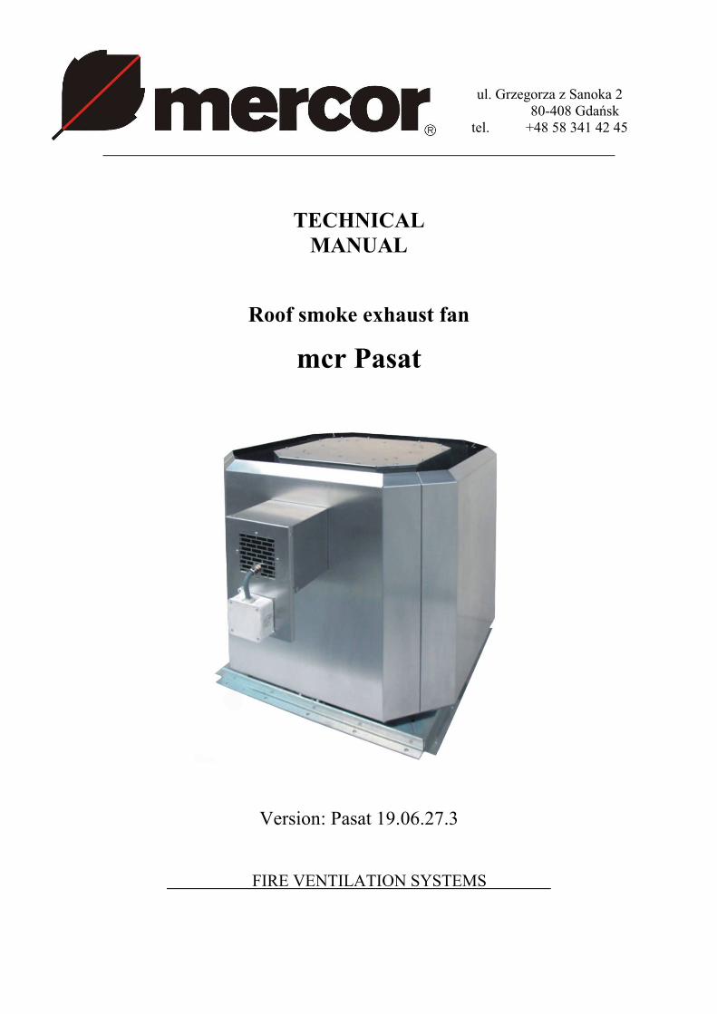
Roof smoke exhaust fan
mcr Pasat
Version: Pasat 19.06.27.3
FIRE VENTILATION SYSTEMS
2/15
CONTENTS:
1. FOREWORD ........................................................................................................................................ 3
2. MANUFACTURER'S DISCLAIMER ..................................................................................................... 3
3. SUBJECT ............................................................................................................................................. 4
4. INTENDED USE .................................................................................................................................. 4
4.1. Application ................................................................................................................................... 4
4.2. Fire resistance ............................................................................................................................. 5
4.3. Versions...................................................................................................................................... 5
5. DESIGN AND OPERATING PRINCIPLE .............................................................................................. 5
5.1. Design ......................................................................................................................................... 5
5.2. Function ....................................................................................................................................... 6
5.3. Dimensions .................................................................................................................................. 6
5.4. Accesories ................................................................................................................................. 7
6. IDENTIFICATION MARKING ............................................................................................................... 9
7. INSTALLATION .................................................................................................................................... 9
7.1. Pre-assembly inspection .............................................................................................................. 9
7.2. Location and assembly ................................................................................................................ 9
7.3. Electrical connections ................................................................................................................ 11
7.4. Commissioning .......................................................................................................................... 12
8. TRANSPORT & STORAGE CONDITIONS......................................................................................... 12
9. SAFETY MANUAL .............................................................................................................................. 12
10. MAINTENANCE & SERVICING ........................................................................................................ 13
11. WARRANTY TERMS & CONDITIONS ............................................................................................. 13
VENTILATOR MEASUREMENT REPORT ............................................................................................ 15
Technical Manual designations □ – available option □ – unavailable option
3/15
CAUTION All previous issues of this Technical Manual expire on the date of issue hereof.
This Technical Manual does not apply to any fans manufactured prior to this Manual's date of issue.
1. FOREWORD__________________________________________________
This Technical Manual is addressed to users/operators of type mcr Pasat roof smoke exhaust fans. This document is intended to provide guidelines on the application, design, commissioning and operation of the product.
Read this Technical Manual thoroughly before installing this equipment at its operating site and commissioning. If the equipment is found malfunctioning or defective, contact the manufacturer or their Authorised Representative.
Due to the continuous product improvement policy, we reserve the right to change the product design in order to improve its performance and safety.
This equipment has been designed and manufactured according to the following standards:
PN-EN 12101-3:2004 Smoke and heat control systems. Part 3: Specification for powered smoke and heat exhaust fans. PN-EN ISO 12100-1:2005 Safety of machinery. Basic concepts, general principles for design. Part 1: Basic terminology, methodology. PN-EN ISO 12100-2:2005 Safety of machinery. Basic concepts, general principles for design. Part 2: Technical principles. PN-EN 60204-1:2001 Safety of machinery. Electrical equipment of machines. Part 1: General requirements. The smoke exhaust fan design also meets the state of the art in technology, while assuring health and safety protection.
2. MANUFACTURER'S DISCLAIMER_______________________________
The manufacturer shall not be liable for any consequences of non-intended use or misuse of the equipment.
DO NOT install any components that are not included in the equipment composition or accessories.
Unauthorised modifications or alteration of this equipment is strictly prohibited. Protect the equipment enclosure (casing) from mechanical damage. Before attempting to install this equipment, verify the load bearing capacity of the structural
elements to which the equipment is to be fastened. Unreliable fastening may result in damage or failure of the equipment and/or be hazardous to all nearby personnel.
This fan is not intended for forcing air with viscous pollutants that may settle on the equipment, and especially on its rotor.
4/15
This fan is not intended for forcing air with corrosive pollutants that may be detrimental to the equipment.
The maximum actual rotor RPM must never exceed the nominal (rated) RPM speed in operation. The manufacturer shall not be liable for any injuries, trauma or other bodily harm caused by
misuse of this equipment.
3. SUBJECT______________________________________
The subject of this Technical Manual is: mcr Pasat F400 roof smoke exhaust radial fans □ mcr Pasat F300 roof smoke exhaust radial fans □ mcr Pasat F200 roof smoke exhaust radial fans □ mcr Pasat F600 roof smoke exhaust radial fans □
4. INTENDED USE___________________________________________________
4.1. Application_________________________________________________________________
The type mcr Pasat roof smoke exhaust fans are intended to remove smoke and heat generated in indoor rooms on fire. The equipment facilitates evacuation of persons from the area on fire, protect the building structure and its furnishing from high temperature, facilitate fire fighting, and inhibit spreading of fire to adjacent fire zones. The available versions include:
single-functional with single-speed motors; two-functional, i.e. for general and fire ventilation and with two-speed motors.
The fans can be installed outdoors: on suitable consoles/roof ventilator bases with the motor in the vertical orientation. The fan overall compression ratio makes them compatible with ventilation systems characterised by relatively high flow resistance.
The fan may force dry air only and with a maximum particulate content of 0.3 g/m³. This fan is not intended for forcing air with viscous pollutants that may settle on the equipment, and especially on its rotor. This fan is not intended for forcing air with corrosive pollutants that may be detrimental to the equipment. The maximum actual rotor RPM must never exceed the nominal (rated) RPM speed in operation.
Following operation in actual fire conditions, the ventilator will not be fit for further use.
5/15
4.2. Fire resistance__________________________________________________________
Class F400 – fire resistance at 400oC for 120 minutes □ Class F300 – fire resistance at 300oC for 60 minutes □ Class F200 – fire resistance at 200oC for 120 minutes □ Class F600 – fire resistance at 600oC for 60 minutes □
4.3. Versions
Single-speed single-functional fans Two-speed two-functional fans
5. DESIGN AND OPERATING PRINCIPLE
5.1. Design ______________________________________________________________________
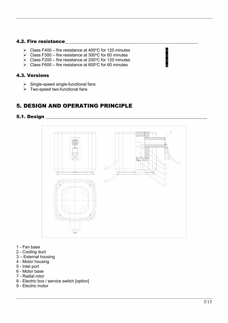
1 - Fan base 2 - Cooling duct 3 – External housing 4 - Motor housing 5 - Inlet port 6 - Motor base 7 - Radial rotor 8 - Electric box / service switch [option] 9 - Electric motor
6/15
The mcr Pasat roof smoke exhaust fan comprises an electrical motor with the insulation class F, a radial rotor and an external housing assembly. The insulated housing encloses the electric motor, on the shaft neck of which the steel rotor is installed. The air intake to the rotor is guided by the inlet port. The rotor is a single-sided suction rotor with swept-back blades. The rotor also features blades which generate vacuum in the motor chamber. This sucks ambient air through the cooling duct. The fan design facilitates draining of water out of the casing. The water to be drained may originate from ingress of rain, melting snow or condensed water vapour from the sucked in air.
5.2. Function ______________________________________________________________________
The single-functional fans do not run in standby. When 3-phase voltage is present on the electric box terminals, the fan is started and running. The two-functional fans run at low speed (RPM) to handle general ventilation under normal conditions. When the fan receives an alarm signal, it automatically starts running with the second speed, which is higher than the first one.
5.3. Dimensions ___________________________________________________________________
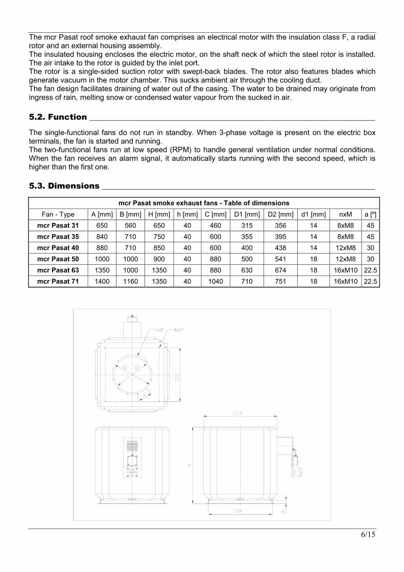
mcr Pasat smoke exhaust fans - Table of dimensions
Fan - Type A [mm] B [mm] H [mm] h [mm] C [mm] D1 [mm] D2 [mm] d1 [mm] nxM a [º]
mcr Pasat 31 650 560 650 40 460 315 356 14 8xM8 45
mcr Pasat 35 840 710 750 40 600 355 395 14 8xM8 45
mcr Pasat 40 880 710 850 40 600 400 438 14 12xM8 30
mcr Pasat 50 1000 1000 900 40 880 500 541 18 12xM8 30
mcr Pasat 63 1350 1000 1350 40 880 630 674 18 16xM10 22.5
mcr Pasat 71 1400 1160 1350 40 1040 710 751 18 16xM10 22.5
7/15
5.4. Accesories____________________________________________________________________
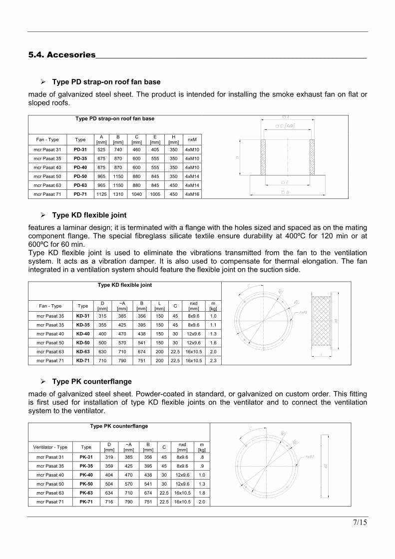
Type PD strap-on roof fan base
made of galvanized steel sheet. The product is intended for installing the smoke exhaust fan on flat or sloped roofs.
Type PD strap-on roof fan base
Fan - Type Type A
[mm] B
[mm] C
[mm] E
[mm] H
[mm] nxM
mcr Pasat 31 PD-31 525 740 460 405 350 4xM10
mcr Pasat 35 PD-35 675 870 600 555 350 4xM10
mcr Pasat 40 PD-40 675 870 600 555 350 4xM10
mcr Pasat 50 PD-50 965 1150 880 845 350 4xM14
mcr Pasat 63 PD-63 965 1150 880 845 450 4xM14
mcr Pasat 71 PD-71 1125 1310 1040 1005 450 4xM16
Type KD flexible joint
features a laminar design; it is terminated with a flange with the holes sized and spaced as on the mating component flange. The special fibreglass silicate textile ensure durability at 400ºC for 120 min or at 600ºC for 60 min. Type KD flexible joint is used to eliminate the vibrations transmitted from the fan to the ventilation system. It acts as a vibration damper. It is also used to compensate for thermal elongation. The fan integrated in a ventilation system should feature the flexible joint on the suction side.
Type KD flexible joint
Fan - Type Type D
[mm] ~A
[mm] B
[mm] L
[mm] C
nxd [mm]
m [kg]
mcr Pasat 35 KD-31 315 385 356 150 45 8x9.6 1.0
mcr Pasat 35 KD-35 355 425 395 150 45 8x9.6 1.1
mcr Pasat 40 KD-40 400 470 438 150 30 12x9.6 1.3
mcr Pasat 50 KD-50 500 570 541 150 30 12x9.6 1.6
mcr Pasat 63 KD-63 630 710 674 200 22.5 16x10.5 2.0
mcr Pasat 71 KD-71 710 790 751 200 22.5 16x10.5 2.3
Type PK counterflange
made of galvanized steel sheet. Powder-coated in standard, or galvanized on custom order. This fitting is first used for installation of type KD flexible joints on the ventilator and to connect the ventilation system to the ventilator.
Type PK counterflange
Ventilator - Type Type D
[mm] ~A
[mm] B
[mm] C
nxd [mm]
m [kg]
mcr Pasat 31 PK-31 319 385 356 45 8x9.6 .8
mcr Pasat 35 PK-35 359 425 395 45 8x9.6 .9
mcr Pasat 40 PK-40 404 470 438 30 12x9.6 1.0
mcr Pasat 50 PK-50 504 570 541 30 12x9.6 1.3
mcr Pasat 63 PK-63 634 710 674 22.5 16x10.5 1.8
mcr Pasat 71 PK-71 716 790 751 22.5 16x10.5 2.0
8/15
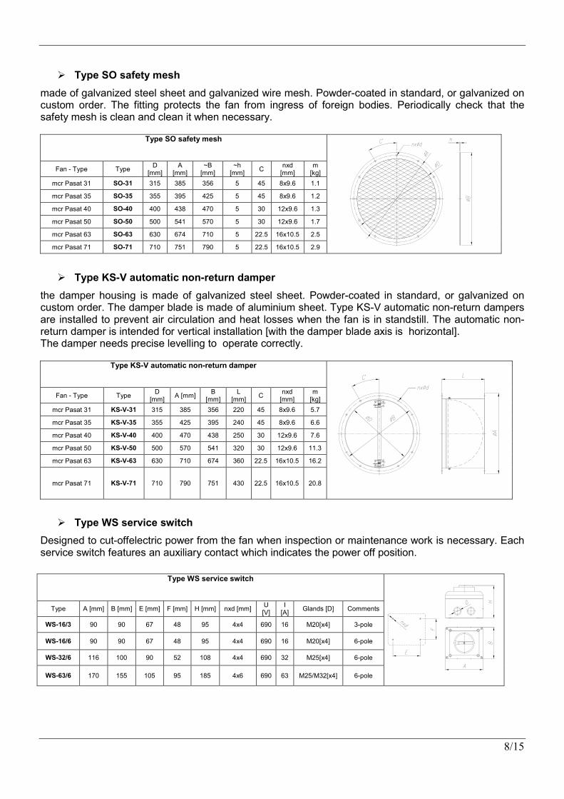
Type SO safety mesh
made of galvanized steel sheet and galvanized wire mesh. Powder-coated in standard, or galvanized on custom order. The fitting protects the fan from ingress of foreign bodies. Periodically check that the safety mesh is clean and clean it when necessary.
Type SO safety mesh
Fan - Type Type D
[mm] A
[mm] ~B
[mm] ~h
[mm] C
nxd [mm]
m [kg]
mcr Pasat 31 SO-31 315 385 356 5 45 8x9.6 1.1
mcr Pasat 35 SO-35 355 395 425 5 45 8x9.6 1.2
mcr Pasat 40 SO-40 400 438 470 5 30 12x9.6 1.3
mcr Pasat 50 SO-50 500 541 570 5 30 12x9.6 1.7
mcr Pasat 63 SO-63 630 674 710 5 22.5 16x10.5 2.5
mcr Pasat 71 SO-71 710 751 790 5 22.5 16x10.5 2.9
Type KS-V automatic non-return damper
the damper housing is made of galvanized steel sheet. Powder-coated in standard, or galvanized on custom order. The damper blade is made of aluminium sheet. Type KS-V automatic non-return dampers are installed to prevent air circulation and heat losses when the fan is in standstill. The automatic non-return damper is intended for vertical installation [with the damper blade axis is horizontal]. The damper needs precise levelling to operate correctly.
Type KS-V automatic non-return damper
Fan - Type Type D
[mm] A [mm]
B [mm]
L [mm]
C nxd
[mm] m
[kg]
mcr Pasat 31 KS-V-31 315 385 356 220 45 8x9.6 5.7
mcr Pasat 35 KS-V-35 355 425 395 240 45 8x9.6 6.6
mcr Pasat 40 KS-V-40 400 470 438 250 30 12x9.6 7.6
mcr Pasat 50 KS-V-50 500 570 541 320 30 12x9.6 11.3
mcr Pasat 63 KS-V-63 630 710 674 360 22.5 16x10.5 16.2
mcr Pasat 71 KS-V-71 710 790 751 430 22.5 16x10.5 20.8
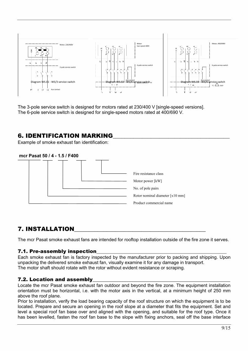
Type WS service switch
Designed to cut-offelectric power from the fan when inspection or maintenance work is necessary. Each service switch features an auxiliary contact which indicates the power off position.
Type WS service switch
Type A [mm] B [mm] E [mm] F [mm] H [mm] nxd [mm] U [V]
I [A]
Glands [D] Comments
WS-16/3 90 90 67 48 95 4x4 690 16 M20[x4] 3-pole
WS-16/6 90 90 67 48 95 4x4 690 16 M20[x4] 6-pole
WS-32/6 116 100 90 52 108 4x4 690 32 M25[x4] 6-pole
WS-63/6 170 155 105 95 185 4x6 690 63 M25/M32[x4] 6-pole
9/15
The 3-pole service switch is designed for motors rated at 230/400 V [single-speed versions]. The 6-pole service switch is designed for single-speed motors rated at 400/690 V.
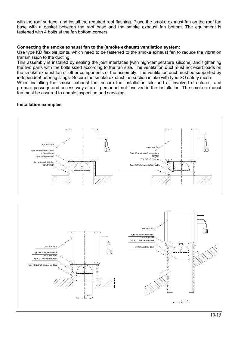
6. IDENTIFICATION MARKING________________________________________ Example of smoke exhaust fan identification:
mcr Pasat 50 / 4 - 1.5 / F400
7. INSTALLATION_____________________________________________
The mcr Pasat smoke exhaust fans are intended for rooftop installation outside of the fire zone it serves.
7.1. Pre-assembly inspection____________________________________________________ Each smoke exhaust fan is factory inspected by the manufacturer prior to packing and shipping. Upon unpacking the delivered smoke exhaust fan, visually examine it for any damage in transport. The motor shaft should rotate with the rotor without evident resistance or scraping.
7.2. Location and assembly_______________________________________________________ Locate the mcr Pasat smoke exhaust fan outdoor and beyond the fire zone. The equipment installation orientation must be horizontal, i.e. with the motor axis in the vertical, at a minimum height of 250 mm above the roof plane. Prior to installation, verify the load bearing capacity of the roof structure on which the equipment is to be located. Prepare and secure an opening in the roof slope at a diameter that fits the equipment. Set and level a special roof fan base over and aligned with the opening, and suitable for the roof type. Once it has been levelled, fasten the roof fan base to the slope with fixing anchors, seal off the base interface
Fire resistance class
Motor power [kW]
No. of pole pairs
Rotor nominal diameter [x10 mm]
Product commercial name
Diagram WS.01 - WS/3 service switch
Motor, 230/400V
3-pole service switch
Aux contact
Diagram WS.02 - WS/6 service switch
Motor two-speed 400V
6-pole service switch
Aux contact
Speed switch, Y - YY Diagram WS.03 - WS/6 service switch
Motor, 400/690V
6-pole service switch
Aux contact
Y / statr
10/15
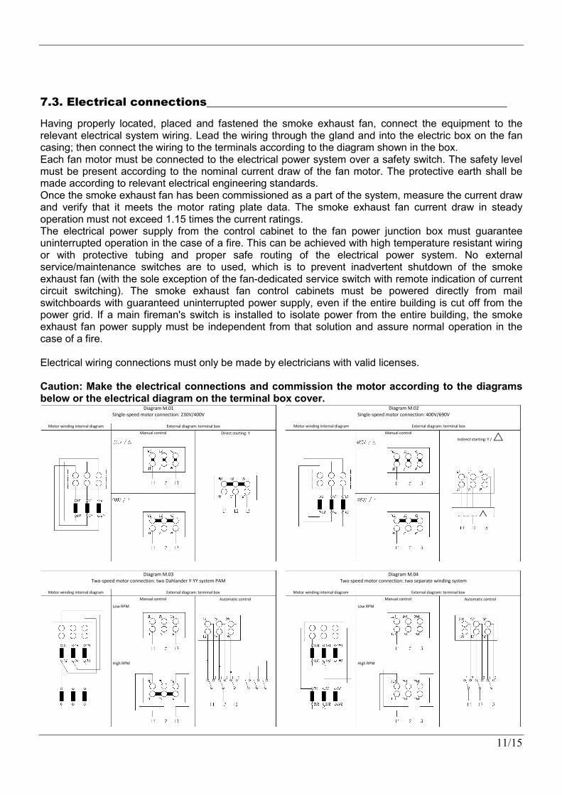
with the roof surface, and install the required roof flashing. Place the smoke exhaust fan on the roof fan base with a gasket between the roof base and the smoke exhaust fan bottom. The equipment is fastened with 4 bolts at the fan bottom corners. Connecting the smoke exhaust fan to the (smoke exhaust) ventilation system: Use type KD flexible joints, which need to be fastened to the smoke exhaust fan to reduce the vibration transmission to the ducting. This assembly is installed by sealing the joint interfaces [with high-temperature silicone] and tightening the two parts with the bolts sized according to the fan size. The ventilation duct must not exert loads on the smoke exhaust fan or other components of the assembly. The ventilation duct must be supported by independent bearing slings. Secure the smoke exhaust fan suction intake with type SO safety mesh. When installing the smoke exhaust fan, secure the installation site and all involved structures, and prepare passage and access ways for all personnel not involved in the installation. The smoke exhaust fan must be assured to enable inspection and servicing.
Installation examples
mcr Pasat fan
Type KS-V automatic non-return damper
Type SO safety mesh
Sockle, installed during construction
mcr Pasat fan
Type KS-V automatic non-return damper
Type SO safety mesh
Type PDN strap-on roof fan base
mcr Pasat fan
Type KS-V automatic non-return damper
Type KD vibration damper
Type PDN strap-on roof fan base
mcr Pasat fan
Type KS-V automatic non-return damper
Type KD vibration damper
Type PDS roof fan base
11/15
7.3. Electrical connections_____________________________________________________
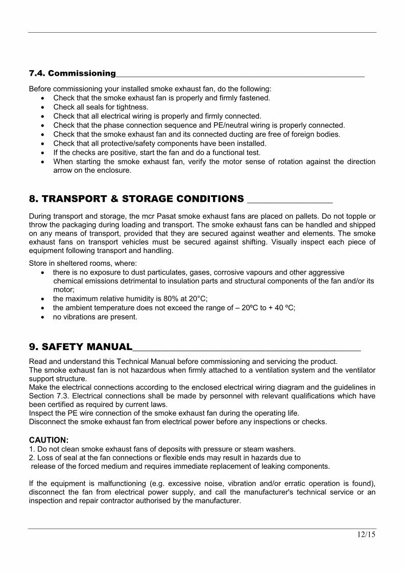
Having properly located, placed and fastened the smoke exhaust fan, connect the equipment to the relevant electrical system wiring. Lead the wiring through the gland and into the electric box on the fan casing; then connect the wiring to the terminals according to the diagram shown in the box. Each fan motor must be connected to the electrical power system over a safety switch. The safety level must be present according to the nominal current draw of the fan motor. The protective earth shall be made according to relevant electrical engineering standards. Once the smoke exhaust fan has been commissioned as a part of the system, measure the current draw and verify that it meets the motor rating plate data. The smoke exhaust fan current draw in steady operation must not exceed 1.15 times the current ratings. The electrical power supply from the control cabinet to the fan power junction box must guarantee uninterrupted operation in the case of a fire. This can be achieved with high temperature resistant wiring or with protective tubing and proper safe routing of the electrical power system. No external service/maintenance switches are to used, which is to prevent inadvertent shutdown of the smoke exhaust fan (with the sole exception of the fan-dedicated service switch with remote indication of current circuit switching). The smoke exhaust fan control cabinets must be powered directly from mail switchboards with guaranteed uninterrupted power supply, even if the entire building is cut off from the power grid. If a main fireman's switch is installed to isolate power from the entire building, the smoke exhaust fan power supply must be independent from that solution and assure normal operation in the case of a fire. Electrical wiring connections must only be made by electricians with valid licenses. Caution: Make the electrical connections and commission the motor according to the diagrams below or the electrical diagram on the terminal box cover.
Diagram M.01 Single-speed motor connection: 230V/400V
Motor winding internal diagram External diagram: terminal box
Manual control Direct starting: Y
Diagram M.02 Single-speed motor connection: 400V/690V
Motor winding internal diagram External diagram: terminal box
Manual control
Indirect starting: Y /
Switch: Y /
Diagram M.03 Two-speed motor connection: two Dahlander Y-YY system PAM
Motor winding internal diagram External diagram: terminal box
Manual control Automatic control
Low RPM
High RPM
Diagram M.04 Two-speed motor connection: two separate winding system
Motor winding internal diagram External diagram: terminal box
Manual control Automatic control
Low RPM
High RPM
12/15
7.4. Commissioning_____________________________________________________________
Before commissioning your installed smoke exhaust fan, do the following: Check that the smoke exhaust fan is properly and firmly fastened. Check all seals for tightness. Check that all electrical wiring is properly and firmly connected. Check that the phase connection sequence and PE/neutral wiring is properly connected. Check that the smoke exhaust fan and its connected ducting are free of foreign bodies. Check that all protective/safety components have been installed. If the checks are positive, start the fan and do a functional test. When starting the smoke exhaust fan, verify the motor sense of rotation against the direction
arrow on the enclosure.
8. TRANSPORT & STORAGE CONDITIONS __________________
During transport and storage, the mcr Pasat smoke exhaust fans are placed on pallets. Do not topple or throw the packaging during loading and transport. The smoke exhaust fans can be handled and shipped on any means of transport, provided that they are secured against weather and elements. The smoke exhaust fans on transport vehicles must be secured against shifting. Visually inspect each piece of equipment following transport and handling.
Store in sheltered rooms, where: there is no exposure to dust particulates, gases, corrosive vapours and other aggressive
chemical emissions detrimental to insulation parts and structural components of the fan and/or its motor;
the maximum relative humidity is 80% at 20°C; the ambient temperature does not exceed the range of – 20ºC to + 40 ºC; no vibrations are present.
9. SAFETY MANUAL________________________________________________
Read and understand this Technical Manual before commissioning and servicing the product. The smoke exhaust fan is not hazardous when firmly attached to a ventilation system and the ventilator support structure. Make the electrical connections according to the enclosed electrical wiring diagram and the guidelines in Section 7.3. Electrical connections shall be made by personnel with relevant qualifications which have been certified as required by current laws. Inspect the PE wire connection of the smoke exhaust fan during the operating life. Disconnect the smoke exhaust fan from electrical power before any inspections or checks. CAUTION: 1. Do not clean smoke exhaust fans of deposits with pressure or steam washers. 2. Loss of seal at the fan connections or flexible ends may result in hazards due to release of the forced medium and requires immediate replacement of leaking components. If the equipment is malfunctioning (e.g. excessive noise, vibration and/or erratic operation is found), disconnect the fan from electrical power supply, and call the manufacturer's technical service or an inspection and repair contractor authorised by the manufacturer.
13/15
10. MAINTENANCE & SERVICING____________________________________
The equipment from Mercor SA require periodic technical inspection and maintenance at least every 12 months throughout its operating life, i.e. during the warranty and post-warranty period. Inspection and maintenance may only be carried out by the manufacturer or contractors authorised by Mercor SA to service its products. Regular service inspections of fire protection equipment is mandatory in Poland according to § 3 Section 3 of the Polish Regulation of the Ministry of the Interior and Administration of 7 June 2010 on the fire protection of buildings, other structures and areas (Polish Journal of Laws, Year 2010, No. 109 Item 719). Do these recommended actions in the inspection intervals:
Check the electrical connections, especially for all mechanical damage. Check the equipment casing, especially for all mechanical damage. Check for any obstructions to proper performance of the equipment.
To facilitate the activities under service inspection, servicing and warranty claim response, e.g. visual inspection or repairs, the equipment user/operator shall provide physical access to the equipment by removing thermal insulation, suspended ceiling, and other installations, as required and applicable to warrant unobstructed access. In the case of roof mounted equipment, provide access to the area (via ladders or elevated platforms). If the equipment is only operated for smoke exhaust during fire, test run it for ca. 10 minutes every 3 months. Refer all matters related to technical inspection, maintenance and servicing of this equipment to the Mercor SA Service Department, [email protected], tel. +48 58 341 42 45 ext. 170, fax: +48 58 341 39 85, from 8 AM to 4 PM (Mo-Fri).
11. WARRANTY TERMS & CONDITIONS ___________________________
1. “MERCOR” SA grants 12 months of warranty for the equipment quality from the date of purchase, unless the sales contract states otherwise.
2. Submit each warranty claim to “MERCOR” SA in 7 days from the date of discovery of a warranty eligible defect
3. Submit warranty claims by calling at: tel. +48 58 341 42 45, by fax: +48 58 341 39 85, by e-mail: [email protected] or by traditional mail: “MERCOR” SA, ul. Grzegorza z Sanoka 2, 80-408 Gdańsk, Poland.
4. If physical defects of equipment are found during the warranty period, “MERCOR” SA warrants and represents to remove them in shortest possible time from serving the written warranty claim with the proof of purchase or sales contract, subject to Item 10.
5. “MERCOR” SA has the right to extend the time of repair if the defect removal is complicated or requires purchase of custom components or spare parts.
6. The warranty liability only covers all defects arising from causes present in the equipment at the date of sale.
7. Defects caused by improper operation or otherwise as listed in Item 10 herein, the buyer / warranty beneficiary will be charged with the costs of their removal.
8. Condition for rectifying defects is that the applicant makes the site/localisation where devices are installed available, in particular, ensuring: the lift in the case of devices mounted at a height above 3m, free access to the rooms where the devices were installed and necessary revisions, dismantling thermal insulation, disassembling suspended ceilings, disassembling other installations, if they prevent free access to the device.
9. If the device can not be repaired at the place of its installation, "MERCOR" SA reserves the necessity of its disassembly, possible delivery to the address indicated by "MERCOR" SA and re-assembly. The cost of this operation lies with the buyer / holder of the guarantee.
14/15
10. The warranty does not cover: Any damage or failure of the equipment caused by improper operation, tampering, failure to
conduct periodic technical inspection and/or maintenance established in the Operating and Maintenance Manual, section “SERVICING AND MAINTENANCE”.
Any damage beyond reasonable control of “MERCOR” SA, and specifically: caused by force majeure, such as torrential rainfall, flooding, hurricanes, inundation, lightning strike, power grid overvoltage, explosion, hail, collision with aircraft, fire, avalanche, landslide and indirect damage due to those causes. Torrential rainfall is understood as any rainfall with the effectiveness factor of 4 or higher in accordance with the definition of the Polish Institute of Meteorology and Water Management - National Research Institute (IMGW-PIB). If the effectiveness factor value specified in the preceding sentence cannot be reasonably established, the actual condition and extent of damage shall be considered at the site of their origin as the action of torrential rain. Hurricane is understood as any wind with a minimum speed of 17.5 m/s (and damage shall be recognised as caused by hurricanes if the effects of such weather phenomenon has been found in the direct vicinity of the damaged property).
Damage due to failure to immediately report any defect found. Deterioration in the quality of coatings due to natural weathering/ageing. Defects caused by abrasive or aggressive cleaning agents. Damage caused by aggressive external influence, specifically chemical or biological in
nature, or when the origin of which is related to the production processing or activity carried out within the facility protected by the equipment or in its direct vicinity.
Wearing parts and consumables (e.g. gaskets/seals), unless they have defects of workmanship and/or material.
Damage caused by improper transport, handling, unloading and/or storage of the equipment. Damage caused by installation of the equipment in violation of this Operating and
Maintenance Manual and/or good construction practice. The equipment and/or parts thereof with removed or damaged nameplate (rating plate)
and/or warranty seals. 11. The buyer/warranty rights holder is required to operate the equipment properly and carry out
technical inspection and maintenance in accordance with the section “MAINTENANCE AND SERVICING” in the following Operating and Maintenance Manual.
12. This warranty shall be made immediately void and null if: The buyer/warranty rights holder modifies the product design without prior authorisation from
“MERCOR” SA. Periodic technical inspection and/or maintenance is not carried out per schedule and/or is
carried out by unauthorised personnel or service providers not authorised to do so by “MERCOR” SA and/or the equipment has not been properly operated.
Unauthorised personnel attempts any intervention in the product outside of the normal operation and maintenance of this equipment.
13. Any circumstances listed in Item 10 will relieve “MERCOR” SA from the obligation of surety. The relevant provisions of the Polish Civil Code shall apply to all matters not regulated in these Warranty Terms & Conditions.
15/15
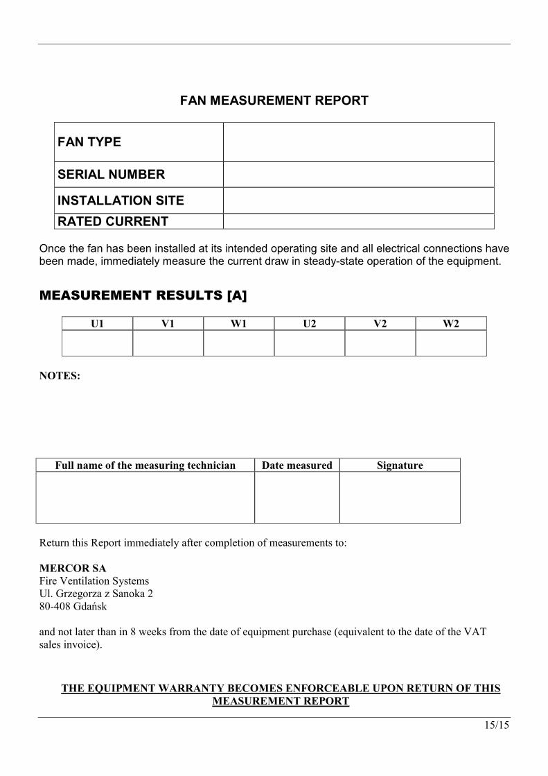
FAN MEASUREMENT REPORT
FAN TYPE
SERIAL NUMBER
INSTALLATION SITE
RATED CURRENT
Once the fan has been installed at its intended operating site and all electrical connections have been made, immediately measure the current draw in steady-state operation of the equipment.
MEASUREMENT RESULTS [A]
U1 V1 W1 U2 V2 W2
NOTES:
Full name of the measuring technician Date measured Signature
Return this Report immediately after completion of measurements to: MERCOR SA Fire Ventilation Systems Ul. Grzegorza z Sanoka 2 80-408 Gdańsk and not later than in 8 weeks from the date of equipment purchase (equivalent to the date of the VAT sales invoice).
THE EQUIPMENT WARRANTY BECOMES ENFORCEABLE UPON RETURN OF THIS MEASUREMENT REPORT