mcrp 2-25a reconaissance reports guide
TRANSCRIPT
MCRP 2-25A (formerly MCRP 2-15.3B)
Reconnaissance Reports Guide
U.S. Marine Corps
PCN 144 000053 00
To Our ReadersChanges: Readers of this publication are encouragedto submit suggestions and changes that will improveit. Recommendations may be sent directly toCommanding General, Doctrine Division (C42),Marine Corps Combat Development Command, 3300Russell Road, Suite 318A, Quantico, VA 22134-5021or by fax to (703) 784-2917 (DSN 278-2917) ore-mail to smb@doctrine [email protected] should include the followinginformation:
Location of change Publication number and title Current page number Paragraph number (if applicable) Line number Figure or table number (if applicable)
Nature of change Add, delete Proposed new text, preferably double-spaced and typewritten
Justification and/or source of information
Additional copies: A printed copy of this publicationmay be obtained from Marine Corps Logistics Base,Albany, GA 31704-5001, by following theinstructions in MCBul 5600, Marine Corps DoctrinalPublications Status. An electronic copy may beobtained from the Doctrine Division, MCCDC, WorldWide Web homepage, which is found at the followinguniform resource locator:http://138.156.107.3/docdiv.

MCCDC (C 42)
13 Jul 2004
E R R A T U M
to
MCRP 2-25A
RECONNAISSANCE REPORTS GUIDE
1. Change the publication short title to read “MCRP 2-25A” (vice MCRP 2-15.3B).
PCN 144 000053 80
DEPARTMENT OF THE NAVYHeadquarters United States Marine Corps
Washington, DC 20380-1775
9 May 2003
CHANGE 1 to MCRP 2-15.3B
1. Marine Corps Reference Publication (MCRP) 2-15.3B, Reconnais-sance Reports Guide, should be changed as follows:
a. On page 5, the table in paragraph b should be replaced withthe updated communications equipment table attached.
2. Reviewed and approved this date.
BY DIRECTION OF THE COMMANDANT OF THE MARINE CORPS
DISTRIBUTION: 144 000053 01
DEPARTMENT OF THE NAVYHeadquarters United States Marine Corps
Washington, DC 20380-177521 April 1998
FOREWORD
1. PURPOSE
Marine Corps Reference Publication (MCRP) 2-15.3B, ReconnaissanceReports Guide, provides tactical reference material on the content andformat of reconnaissance reports. It is intended as a reference aid fortactical field use and is based on information contained in numerousdoctrinal publications available to Marines. This publication is intended tobe used not as a replacement for those source publications, but as a handycompilation of important tactical information.
2. SCOPE
MCRP 2-15.3B contains reference material that is frequently used in thecollection and reporting of information resulting from Marine ground-reconnaissance operations. This publication was prepared primarily toassist reconnaissance patrol leaders and communicators functioning at theteam level and the parent organization or supported unit to which thereconnaissance element may report. Leaders and staffs of supportedorganizations should also have knowledge of the contents of this manualso that they may have compatible reporting formats and, thereby,increased accuracy and consistency of reported information. Thispublication is in a loose-leaf format to better facilitate its use.

3. SUPERSESSION
None. This is a new publication that is based on information contained inlocally produced publications and existing doctrinal manuals.
4. CERTIFICATION
Reviewed and approved this date.
BY DIRECTION OF THE COMMANDANT OF THE MARINECORPS
J.E. RHODESLieutenant General, U.S. Marine Corps
Commanding GeneralMarine Corps Combat Development Command
DISTRIBUTION: 144 000053 00
Unless otherwise specified, masculine nouns andpronouns used in this publication refer to both
men and women.
Record of Changes
Log completed change action as indicated.ChangeNumber
Date ofChange
DateEntered
Signature of PersonIncorporated Change
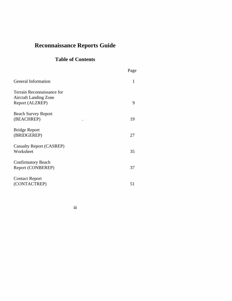
Reconnaissance Reports Guide
Table of Contents
Page
General Information 1
Terrain Reconnaissance for Aircraft Landing Zone Report (ALZREP) 9
Beach Survey Report (BEACHREP) . 19
Bridge Report (BRIDGEREP) 27
Casualty Report (CASREP) Worksheet 35
Confirmatory Beach Report (CONBEREP) 37
Contact Report (CONTACTREP) 51
iii

River/Estuary Report (DELTAREP) 55
Drop Zone Report (DZREP) 65
Flash/Action Report (FLASHREP) and Worksheet 77 Frequency Interference Report (FIRREP) and Worksheet 81
River/Ford Report (FORDREP) 83
Helicopter Landing Site Report (HELLSREP) 89
Meaconing, Intrusion, Jamming, Interference Report (MIJIREP) and Worksheet 103
Nuclear, Biological, and ChemicalReport (NBCREP) 105
Railroad Reconnaissance Report (RAILREP) 109
Route and Road Report (ROUTEREP) 117
iv
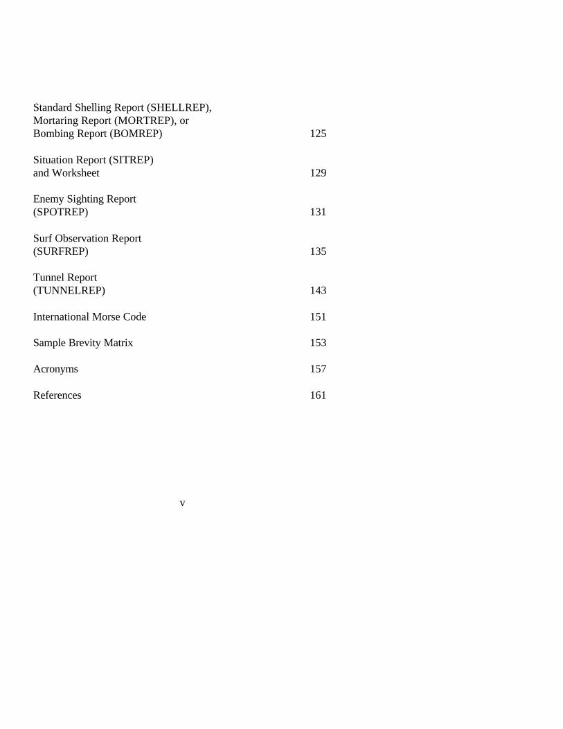
Standard Shelling Report (SHELLREP),Mortaring Report (MORTREP), or Bombing Report (BOMREP) 125
Situation Report (SITREP)and Worksheet 129
Enemy Sighting Report (SPOTREP) 131
Surf Observation Report (SURFREP) 135
Tunnel Report (TUNNELREP) 143
International Morse Code 151
Sample Brevity Matrix 153
Acronyms 157
References 161
v

General Information
1001. General. The purpose of report formats is to provide informationin a standardized format within or between units. Standardized formatssimplify and speed the accurate, timely flow of reports from informationcollectors to information analysts. Formats help to minimize confusionand assist the generation of tempo. In modern warfare, one can expect toconduct operations as part of a joint or allied/coalition force; this makesthe disciplined use of accepted formats a requirement.
1002. Organization. A common listing of units of measurement isfound in paragraph 1006. This paragraph lists codes for each unit ofmeasurement that may be used throughout a particular report; these codesare common to all succeeding formats. Each individual report format in-cluded within this publication (Appendices A through U) is internally or-ganized to provide a logical sequence for reporting the requiredinformation. The information comprising the report is organized to sup-port analysis and ensure completeness of data. The information is ar-ranged as a series of fields; each field contains adequate space forreporting in sufficient detail. The formats also support the use of brevitycodes, which minimize transmission time and thereby increase the prob-ability of survival for the reconnaissance patrol.
1003. Use. The formats in Appendices A through U are intended for useby the information collector for transmission of reports to the organizationrequiring that information. These reports may be used to provide initial in-formation on specific objectives or areas. They may also be used to con-firm or amplify information that is already known or reported.
MCRP 2-15.3B Reconnaissance ReportsGuide

1004. Training. Proper use of report formats requires training and prac-tice. The reconnaissance team leader is responsible for the proper collec-tion and reporting of information. That responsibility includes propertraining and rehearsal of message reporting using these formats. To savevaluable space in this field guide, completed examples of report formatshave not been included. Detailed information on how to properly acquire,record, and report the required information may be found at the residentbasic reconnaissance courses or within reconnaissance units. Proficiencyshould be developed through constant practice in collecting, formatting,sending, and receiving reports.
1005. Technological Advances. The acquisition and fielding of commu-nications devices such as the digital automated communications terminal(DACT) and other similar systems will greatly increase the speed of thedrafting and transmission of tactical reports. These devices will containpreformatted message menus and digital burst transmission features to in-crease accuracy, dependability, and team survivability, but they probablywill not eliminate the requirement to maintain voice or continuous wave(CW) transmission capability. Aside from backup capability in the eventof equipment failure, it may also be necessary to communicate nondigi-tally with allied or coalition partners.
1006. Units of Measurement
a. General. Line ALPHA of all of the appended reports indicates,through inclusion of relevant number codes, which units of measure-ment are referred to in the report text. Selections of units of measure-ment are made from the list below. Once designated in line ALPHA,the units of measurement are used consistently throughout that par-ticular report.
2 Reports FormatMCRP 2-15.3B Reconnaissance Reports
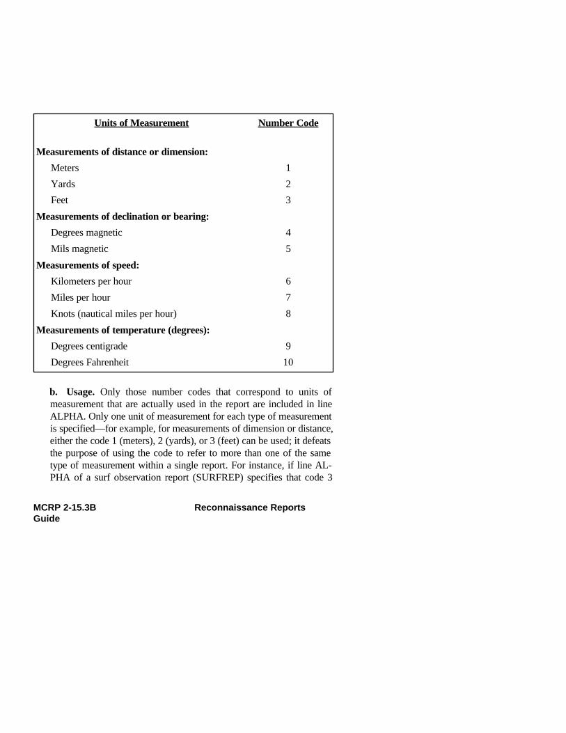
Units of Measurement Number Code
Measurements of distance or dimension:
Meters 1Yards 2Feet 3
Measurements of declination or bearing:
Degrees magnetic 4Mils magnetic 5
Measurements of speed:
Kilometers per hour 6Miles per hour 7Knots (nautical miles per hour) 8
Measurements of temperature (degrees):
Degrees centigrade 9Degrees Fahrenheit 10
b. Usage. Only those number codes that correspond to units ofmeasurement that are actually used in the report are included in lineALPHA. Only one unit of measurement for each type of measurementis specified—for example, for measurements of dimension or distance,either the code 1 (meters), 2 (yards), or 3 (feet) can be used; it defeatsthe purpose of using the code to refer to more than one of the sametype of measurement within a single report. For instance, if line AL-PHA of a surf observation report (SURFREP) specifies that code 3
MCRP 2-15.3B Reconnaissance ReportsGuide
(feet) is used as the unit of measurement, all measurements within thatreport are given in feet, not in meters or yards. This keepsmeasurement-unit use consistent throughout the report. If it is essen-tial to use units of measurement that are different from those speci-fied, these units of measurement must be stated specifically each timethey are used in the text.
1007. General Communications Information
a. Primary Means of Communication. Radio is the primary meansof communication for a reconnaissance patrol. Because reconnais-sance patrols may operate at great distances from friendly positions, itis important that reconnaissance patrol leaders know the planningrange of their radios and how to increase this range by using field-expedient antennas. Because of the electronic signature emitted bytransmitting radios, it is imperative that reconnaissance patrols main-tain the highest degree of communications security by shortening ra-dio transmission lengths, by properly using thecommunications-electronics operating instructions (CEOI) andauthorized brevity codes, by encrypting transmissions, and by usingdirectional antennas to minimize detection.
4 Reports FormatMCRP 2-15.3B Reconnaissance Reports
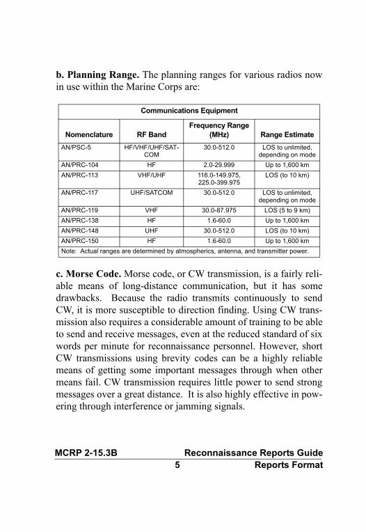
b. Planning Range. The planning ranges for various radios nowin use within the Marine Corps are:
c. Morse Code. Morse code, or CW transmission, is a fairly reli-able means of long-distance communication, but it has somedrawbacks. Because the radio transmits continuously to sendCW, it is more susceptible to direction finding. Using CW trans-mission also requires a considerable amount of training to be ableto send and receive messages, even at the reduced standard of sixwords per minute for reconnaissance personnel. However, shortCW transmissions using brevity codes can be a highly reliablemeans of getting some important messages through when othermeans fail. CW transmission requires little power to send strongmessages over a great distance. It is also highly effective in pow-ering through interference or jamming signals.
Communications Equipment
Nomenclature RF BandFrequency Range
(MHz) Range EstimateAN/PSC-5 HF/VHF/UHF/SAT-
COM30.0-512.0 LOS to unlimited,
depending on modeAN/PRC-104 HF 2.0-29.999 Up to 1,600 kmAN/PRC-113 VHF/UHF 116.0-149.975,
225.0-399.975LOS (to 10 km)
AN/PRC-117 UHF/SATCOM 30.0-512.0 LOS to unlimited, depending on mode
AN/PRC-119 VHF 30.0-87.975 LOS (5 to 9 km)AN/PRC-138 HF 1.6-60.0 Up to 1,600 kmAN/PRC-148 UHF 30.0-512.0 LOS (to 10 km)AN/PRC-150 HF 1.6-60.0 Up to 1,600 kmNote: Actual ranges are determined by atmospherics, antenna, and transmitter power.
MCRP 2-15.3B Reconnaissance Reports Guide5 Reports Format

Appendix V contains a Morse code chart to assist in refreshing thememory of the radio operator for those situations requiring CW capa-bility. For more information on CW transmissions, see Fleet MarineForce manual (FMFM) 3-30, Communications.
d. Brevity Codes. Use of brevity codes can help to reduce transmis-sion times and thereby increase the survivability of the reconnaissanceteam. The key to brevity-code use is strict control of codes. Control isexercised not only by clearly establishing procedures for use and ac-tual codes, but also by limiting distribution to those who have a clearneed. Codes should be rotated periodically to prevent unauthorizeduse or interception. An example of a locally produced brevity codematrix can be found in Appendix W.
e. Field-Expedient Antennas. Field-expedient antennas are tempo-rary antennas designed and constructed by the user to increase therange of tactical radio sets. Field-expedient antennas provide in-creased signal efficiency through the use of an antenna that is specifi-cally designed for the operating frequency in use, through elevation ofthe antenna above ground, or by concentrating the radiated signalalong a given direction. Field-expedient antennas are easily con-structed from MD-1-type communications wire (or a similar substi-tute, such as copper wire) by using poles or trees to provide support.The most important considerations are site location and physical loca-tion of the radio set within the site, whatever type of antenna is used.
6 Reports FormatMCRP 2-15.3B Reconnaissance Reports Guide
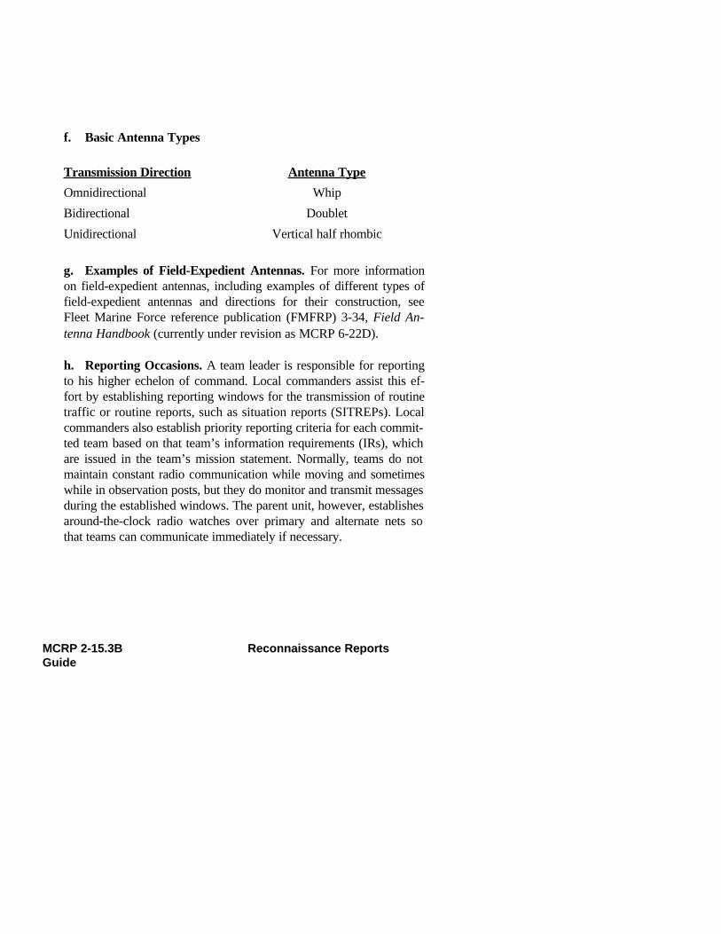
f. Basic Antenna Types
Transmission Direction Antenna Type
Omnidirectional WhipBidirectional DoubletUnidirectional Vertical half rhombic
g. Examples of Field-Expedient Antennas. For more informationon field-expedient antennas, including examples of different types offield-expedient antennas and directions for their construction, seeFleet Marine Force reference publication (FMFRP) 3-34, Field An-tenna Handbook (currently under revision as MCRP 6-22D).
h. Reporting Occasions. A team leader is responsible for reportingto his higher echelon of command. Local commanders assist this ef-fort by establishing reporting windows for the transmission of routinetraffic or routine reports, such as situation reports (SITREPs). Localcommanders also establish priority reporting criteria for each commit-ted team based on that team’s information requirements (IRs), whichare issued in the team’s mission statement. Normally, teams do notmaintain constant radio communication while moving and sometimeswhile in observation posts, but they do monitor and transmit messagesduring the established windows. The parent unit, however, establishesaround-the-clock radio watches over primary and alternate nets sothat teams can communicate immediately if necessary.
MCRP 2-15.3B Reconnaissance ReportsGuide
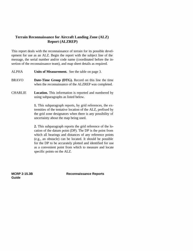
Terrain Reconnaissance for Aircraft Landing Zone (ALZ) Report (ALZREP)
This report deals with the reconnaissance of terrain for its possible devel-opment for use as an ALZ. Begin the report with the subject line of themessage, the serial number and/or code name (coordinated before the in-sertion of the reconnaissance team), and map sheet details as required.
ALPHA Units of Measurement. See the table on page 3.
BRAVO Date-Time Group (DTG). Record on this line the timewhen the reconnaissance of the ALZREP was completed.
CHARLIE Location. This information is reported and numbered byusing subparagraphs as listed below.
1. This subparagraph reports, by grid references, the ex-tremities of the tentative location of the ALZ, prefixed bythe grid zone designators when there is any possibility ofuncertainty about the map being used.
2. This subparagraph reports the grid reference of the lo-cation of the datum point (DP). The DP is the point fromwhich all bearings and distances of any reference points(e.g., an obstacle) can be located. It should be possiblefor the DP to be accurately plotted and identified for useas a convenient point from which to measure and locatespecific points on the ALZ.
MCRP 2-15.3B Reconnaissance ReportsGuide
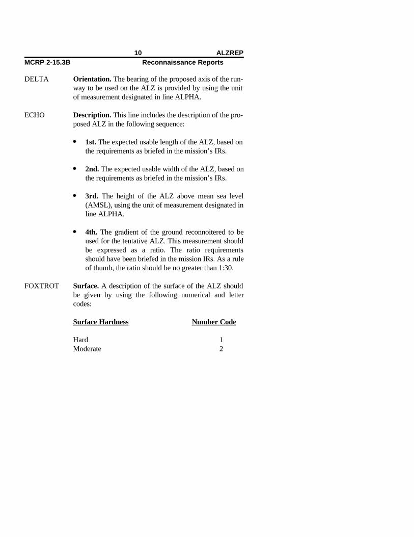
DELTA Orientation. The bearing of the proposed axis of the run-way to be used on the ALZ is provided by using the unitof measurement designated in line ALPHA.
ECHO Description. This line includes the description of the pro-posed ALZ in the following sequence:
1st. The expected usable length of the ALZ, based onthe requirements as briefed in the mission’s IRs.
2nd. The expected usable width of the ALZ, based onthe requirements as briefed in the mission’s IRs.
3rd. The height of the ALZ above mean sea level(AMSL), using the unit of measurement designated inline ALPHA.
4th. The gradient of the ground reconnoitered to beused for the tentative ALZ. This measurement shouldbe expressed as a ratio. The ratio requirementsshould have been briefed in the mission IRs. As a ruleof thumb, the ratio should be no greater than 1:30.
FOXTROT Surface. A description of the surface of the ALZ shouldbe given by using the following numerical and lettercodes:
Surface Hardness Number Code
Hard 1Moderate 2
10 ALZREPMCRP 2-15.3B Reconnaissance Reports

Soft 3
ALZ Surface Letter Code
Sand AGrass BScrub CSnow DIce ECoral FMarsh GOther (describe briefly) H
GOLF Drainage. A brief description of the drainage characteris-tics of the area should be reported in the followingsequence:
1st. The grid reference of any water sources thatcould contribute to flooding of the ALZ. A brief de-scription of the water source should follow the gridreference.
2nd. An indication of whether the ALZ has anysurface/standing water. Transmit a Y (yes) or an N(no).
3rd. The grid references of any streams,ditches, or other water exits that could be used to as-sist in draining the ALZ. The grid reference should befollowed by a brief description of the type ofdrainage.
MCRP 2-15.3B Reconnaissance ReportsGuide
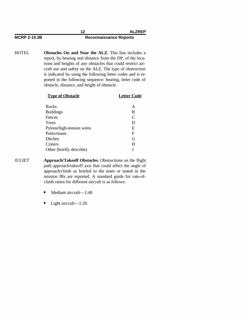
HOTEL Obstacles On and Near the ALZ. This line includes areport, by bearing and distance from the DP, of the loca-tions and heights of any obstacles that could restrict air-craft use and safety on the ALZ. The type of obstructionis indicated by using the following letter codes and is re-ported in the following sequence: bearing, letter code ofobstacle, distance, and height of obstacle.
Type of Obstacle Letter Code
Rocks ABuildings BFences CTrees DPylons/high-tension wires EPoles/masts FDitches GCraters HOther (briefly describe) J
JULIET Approach/Takeoff Obstacles. Obstructions on the flightpath approach/takeoff axis that could affect the angle ofapproach/climb as briefed to the team or stated in themission IRs are reported. A standard guide for rate-of-climb ratios for different aircraft is as follows:
Medium aircraft—1:40
Light aircraft—1:20.
12 ALZREPMCRP 2-15.3B Reconnaissance Reports
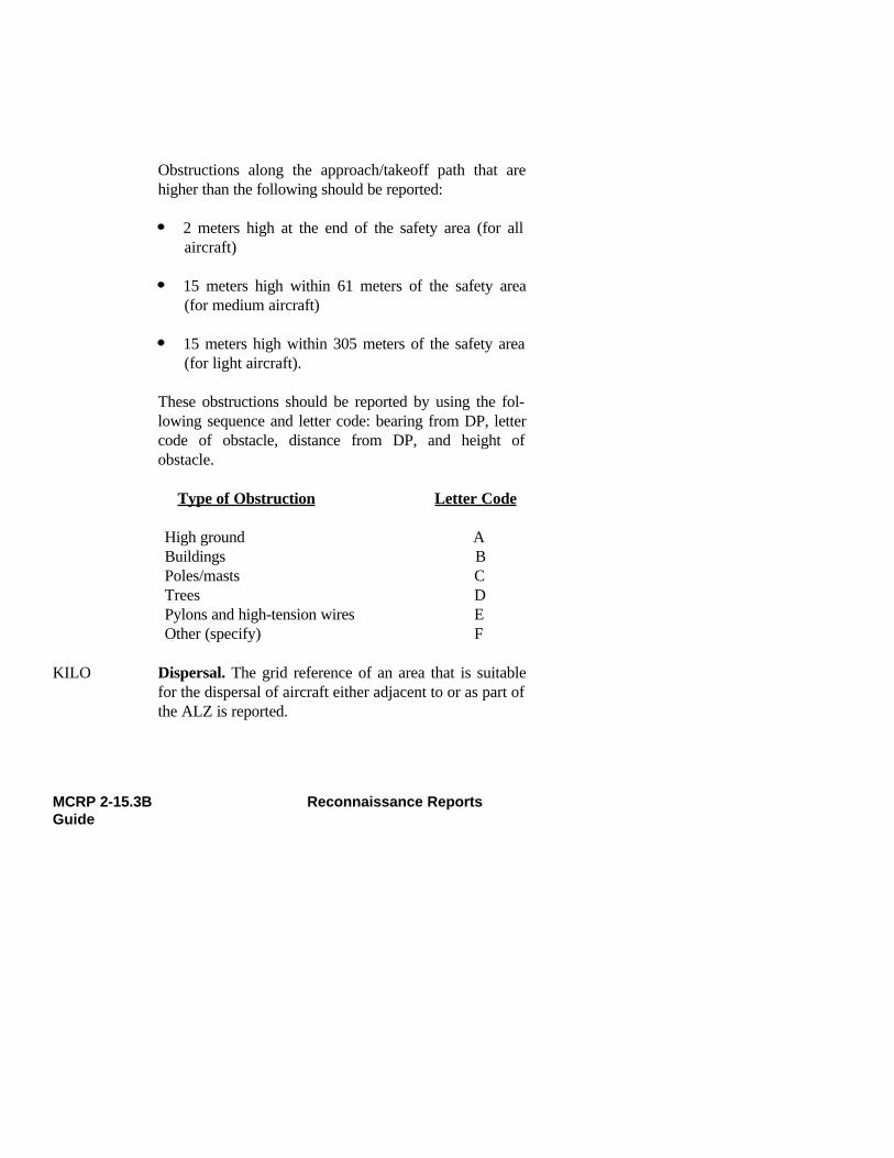
Obstructions along the approach/takeoff path that arehigher than the following should be reported:
2 meters high at the end of the safety area (for allaircraft)
15 meters high within 61 meters of the safety area(for medium aircraft)
15 meters high within 305 meters of the safety area(for light aircraft).
These obstructions should be reported by using the fol-lowing sequence and letter code: bearing from DP, lettercode of obstacle, distance from DP, and height ofobstacle.
Type of Obstruction Letter Code
High ground ABuildings BPoles/masts CTrees DPylons and high-tension wires EOther (specify) F
KILO Dispersal. The grid reference of an area that is suitablefor the dispersal of aircraft either adjacent to or as part ofthe ALZ is reported.
MCRP 2-15.3B Reconnaissance ReportsGuide

LIMA Exits. This includes a report of the grid reference(s) ofpossible road/trail exits from the ALZ to local lines ofcommunications.
MIKE Enemy. Known enemy positions, strengths, and weaponsare to be reported in the following sequence: sightingnumber, grid reference of sighting, strength, and weaponsobserved that could be critical to the accomplishment ofthe ALZ mission.
Note: An enemy sighting report (SPOTREP)/size, activ-ity, location, unit, time, and equipment (SALUTE) reportshould normally be provided in addition to this report toamplify these enemy sightings and further clarify the en-emy situation and possible intentions.
NOVEMBER Local Resources. This line describes resources that areavailable to engineers to use for airfield improvementsand further construction. These should be reported by us-ing the following codes:
Type of Material Number Code
Gravel 1Rock 2Sand 3Water 4Timber 5Other (specify and describe) 6
14 ALZREPMCRP 2-15.3B Reconnaissance Reports

Quantity of Material Letter Code
Large AMedium BSmall C
Note: Quantity estimation is to be related to the task to beachieved and should be prebriefed during patrol planningand published in the team’s IRs.
PAPA Remarks. Other information that is not covered in the re-port but that could prove vital to the accomplishment ofthe supported unit’s mission and scheme of maneuver isprovided. This information should be covered in the pa-trol’s IRs.
Notes:
1. Lines need not be transmitted if they are either notknown or not required. NC (no change) can be used toconfirm information given in the reconnaissance briefing.
2. In the event that ground reconnaissance of an existingairfield is necessary, the above format will be supple-mented with prebriefed IRs for reporting the usefulness ofexisting facilities and their vulnerability to destruction byoccupying enemy forces.
MCRP 2-15.3B Reconnaissance ReportsGuide

ALZREP Worksheet
__________________ this is _________________(receiver) (sender)
ALZREP - (serial number followed by code name and map sheet detailsas required)
ALPHA -
BRAVO -
CHARLIE - (C1)
(C2)
DELTA -
ECHO - (E1)
(E2)
(E3)
(E4)
FOXTROT -
16 ALZREPMCRP 2-15.3B Reconnaissance Reports

GOLF - (G1)
(G2)
(G3)
HOTEL -
JULIET -
KILO - LIMA -
MIKE -
NOVEMBER -
PAPA (remarks) -
DTG -
MCRP 2-15.3B Reconnaissance ReportsGuide

Beach Survey Report (BEACHREP)
Begin with the subject line of the message and the serial number, followedby the code name and map sheet details as required.
ALPHA Units of Measurement. See the table on page 3.
BRAVO Location. This line includes grid coordinates of left andright flanks of the beach being surveyed.
CHARLIE Shape of the Beach. The type of beach is reported by us-ing the following numerical code:
Beach Shape Number Code
Concave 1Convex 2Straight 3Other (specify and describe) 4
DELTA Beach Length. The distance between the two beachflanks is reported in the unit of measurement designatedin line ALPHA.
ECHO Beach Width. The distance from the high-water line tothe hinterland is provided.
MCRP 2-15.3B Reconnaissance ReportsGuide

FOXTROT Gradient. This line provides the gradient of the beachfrom the foreshore to the backshore. The gradient shouldbe estimated by using the following letter code:
Gradient Letter Code
Flat—flatter than 1:120 VMild—1:61 to 1:120 WGentle—1:31 to 1:60 XModerate—1:16 to 1:30 YSteep—steeper than 1:15 Z
GOLF Beach Exits. This line gives the description of all beachexit points. All beach exits are listed sequentially, begin-ning with one, and described individually. Beach exits aredescribed in the following sequence:
1. Grid reference of the beach exit.
2. Beach exit description using the following letter code:
Beach Exit Description Letter Code
Infantry. If the exit is usable Aby infantry only.
Tracked Vehicles. If the exit Bis usable by both trackedvehicles and infantry.
Wheeled Vehicles. If the exit Cis usable by infantry and wheeled traffic.
20 BEACHREPMCRP 2-15.3B Reconnaissance Reports

Unusable. If an area was Dpreviously determined to be abeach exit but as of this timeis unusable for any type of exitfrom the beach.
3. Width of the beach exit, using the unit of measurementdesignated in line ALPHA.
4. Trafficability of the beach exit if it can support vehicletraffic. Use the letter code from line HOTEL.
HOTEL Beach Trafficability. This line provides a general de-scription of the beach’s ability to support vehicle traffic.The following letter code will be used to report thisinformation.
Beach Trafficability Letter Code
Firm. The beach will support W2-wheel-drive vehicles or 4-wheel-drive vehicles withtrailers unless heavycontinuous use is intended.
Moderate. The beach can be used Xby 3- or 5-ton vehicles, which shouldbe able to start from rest by usingall-wheel drive. Recommendusing beach matting/roadway.
MCRP 2-15.3B Reconnaissance ReportsGuide

Soft. Four-wheel-drive vehicles Ycannot start from rest but mightbe able to cross the beach if alreadyon the move. Recommend usingbeach matting/roadway.
Very Soft. The beach is impassable Zto wheeled vehicles, and trackedvehicles may experience difficulty.Use of beach matting/roadway isrequired.
Note: If there is a marked difference in the trafficabilityalong the beach, this must be reported. Use the same let-ter code and any previously coordinated method of loca-tion to designate where the beach trafficability changes,followed by the present trafficability code.
JULIET Littoral Drift. Littoral drift is a current moving parallelto the beach. This information is reported in the unit ofmeasurement designated in line ALPHA. The velocity ofthe current is reported to the nearest one-tenth of a knot.Direction of the current is reported L (left) or R (right) asviewed from seaward, as if the recorder were a coxswainin a boat heading toward the beach. This information isreported in the following sequence:
1st. Velocity of current to the nearest one-tenth of aknot.
2nd. Direction of the current as viewed fromseaward L (left) or R (right).
22 BEACHREPMCRP 2-15.3B Reconnaissance Reports

3rd. DTG of when this information was recorded.
Note: One knot is equal to 100 feet (31 meters) of drift inone minute. This information can be calculated by meas-uring the distance that an object floating in the watertravels in one minute parallel to the beach. This methodwill also give the recorder the direction of the current.
KILO Enemy. If the enemy has been observed or contacted,state Y (yes) and submit a SPOTREP/SALUTE reportseparately. If no enemy has been observed, report NIL inthis line of the report.
LIMA Remarks. Any other information is provided that may becritical to the accomplishment of an amphibious landingon the beach being reconnoitered. Requirements for infor-mation should be covered in the patrol’s IRs.
MCRP 2-15.3B Reconnaissance ReportsGuide

BEACHREP Worksheet
_______________ this is _______________(receiver) (sender)
BEACHREP - (serial number followed by code name and map sheet details as required)
ALPHA -
BRAVO - CHARLIE - DELTA -
ECHO -
FOXTROT -
GOLF -
HOTEL -
JULIET -
KILO -
24 BEACHREPMCRP 2-15.3B Reconnaissance Reports

LIMA (remarks) -
DTG -
MCRP 2-15.3B Reconnaissance ReportsGuide
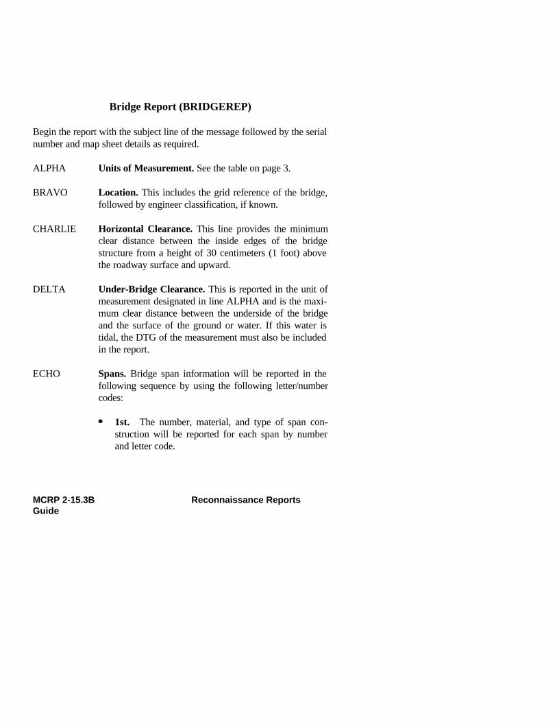
Bridge Report (BRIDGEREP)
Begin the report with the subject line of the message followed by the serialnumber and map sheet details as required.
ALPHA Units of Measurement. See the table on page 3.
BRAVO Location. This includes the grid reference of the bridge,followed by engineer classification, if known.
CHARLIE Horizontal Clearance. This line provides the minimumclear distance between the inside edges of the bridgestructure from a height of 30 centimeters (1 foot) abovethe roadway surface and upward.
DELTA Under-Bridge Clearance. This is reported in the unit ofmeasurement designated in line ALPHA and is the maxi-mum clear distance between the underside of the bridgeand the surface of the ground or water. If this water istidal, the DTG of the measurement must also be includedin the report.
ECHO Spans. Bridge span information will be reported in thefollowing sequence by using the following letter/numbercodes:
1st. The number, material, and type of span con-struction will be reported for each span by numberand letter code.
MCRP 2-15.3B Reconnaissance ReportsGuide

2nd. Spans will be listed in sequence starting fromthe west, or if a bridge is running close to a headingof north/south, the spans will be listed from the northto the south and the letter N will be inserted beforethe span information.
3rd. Material of the span construction will be re-ported by using the following letter codes:
Type of Material Letter Code
Steel or other metal AConcrete KReinforced concrete AKPrestressed concrete KKStone or brick PWood HOther material (specify or describe) M
4th. The type of span construction will be shownfor each span by using the following numerical code:
Type of Span Number Code
Truss 1Girders 2Beams 3Slab 4Arch (closed spandrel) 5Arch (open spandrel) 6Suspension 7Floating 8
28 BRIDGEREPMCRP 2-15.3B Reconnaissance Reports
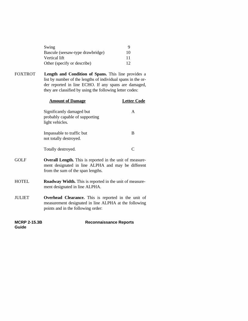
Swing 9Bascule (seesaw-type drawbridge) 10Vertical lift 11Other (specify or describe) 12
FOXTROT Length and Condition of Spans. This line provides alist by number of the lengths of individual spans in the or-der reported in line ECHO. If any spans are damaged,they are classified by using the following letter codes:
Amount of Damage Letter Code
Significantly damaged but Aprobably capable of supportinglight vehicles.
Impassable to traffic but Bnot totally destroyed.
Totally destroyed. C
GOLF Overall Length. This is reported in the unit of measure-ment designated in line ALPHA and may be differentfrom the sum of the span lengths.
HOTEL Roadway Width. This is reported in the unit of measure-ment designated in line ALPHA.
JULIET Overhead Clearance. This is reported in the unit ofmeasurement designated in line ALPHA at the followingpoints and in the following order:
MCRP 2-15.3B Reconnaissance ReportsGuide
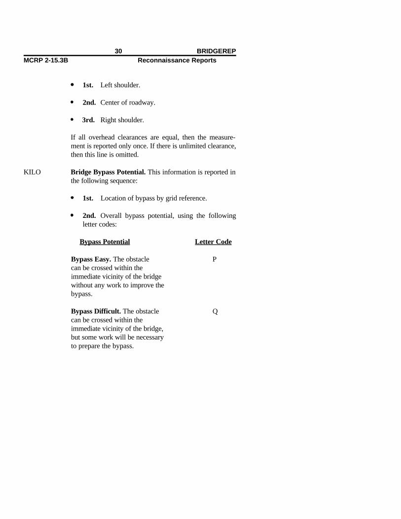
1st. Left shoulder.
2nd. Center of roadway.
3rd. Right shoulder.
If all overhead clearances are equal, then the measure-ment is reported only once. If there is unlimited clearance,then this line is omitted.
KILO Bridge Bypass Potential. This information is reported inthe following sequence:
1st. Location of bypass by grid reference.
2nd. Overall bypass potential, using the followingletter codes:
Bypass Potential Letter Code
Bypass Easy. The obstacle Pcan be crossed within theimmediate vicinity of the bridgewithout any work to improve thebypass.
Bypass Difficult. The obstacle Qcan be crossed within theimmediate vicinity of the bridge,but some work will be necessaryto prepare the bypass.
30 BRIDGEREPMCRP 2-15.3B Reconnaissance Reports
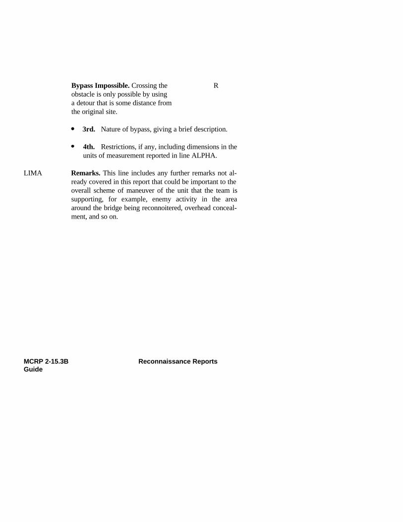
Bypass Impossible. Crossing the Robstacle is only possible by using a detour that is some distance from the original site.
3rd. Nature of bypass, giving a brief description.
4th. Restrictions, if any, including dimensions in theunits of measurement reported in line ALPHA.
LIMA Remarks. This line includes any further remarks not al-ready covered in this report that could be important to theoverall scheme of maneuver of the unit that the team issupporting, for example, enemy activity in the areaaround the bridge being reconnoitered, overhead conceal-ment, and so on.
MCRP 2-15.3B Reconnaissance ReportsGuide
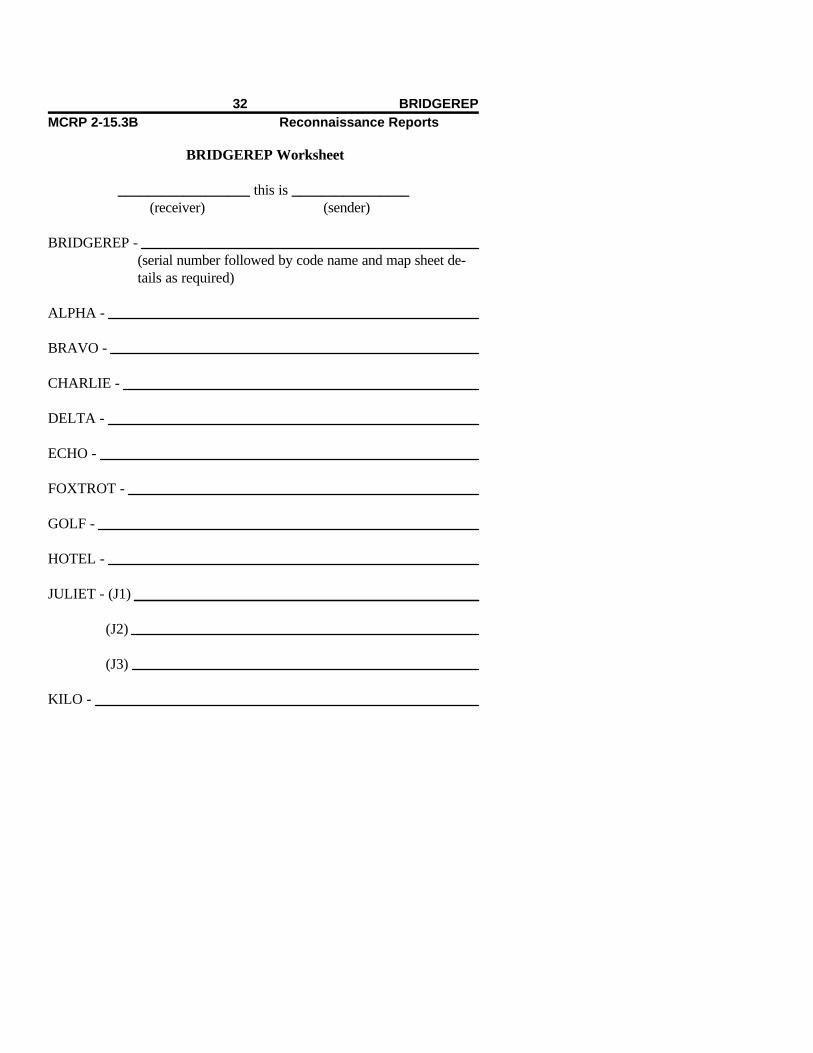
BRIDGEREP Worksheet
__________________ this is ________________(receiver) (sender)
BRIDGEREP - (serial number followed by code name and map sheet de-tails as required)
ALPHA -
BRAVO -
CHARLIE -
DELTA -
ECHO -
FOXTROT -
GOLF -
HOTEL -
JULIET - (J1)
(J2)
(J3)
KILO -
32 BRIDGEREPMCRP 2-15.3B Reconnaissance Reports

LIMA (remarks) -
DTG -
MCRP 2-15.3B Reconnaissance ReportsGuide
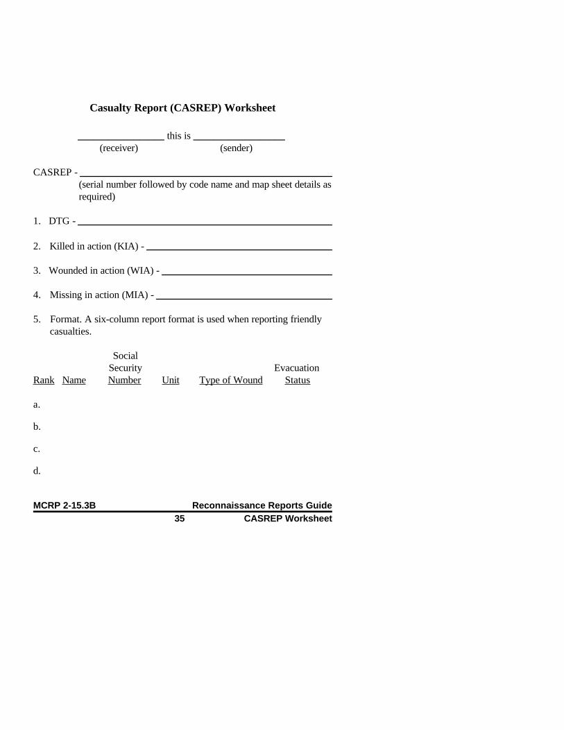
Casualty Report (CASREP) Worksheet
_________________ this is __________________ (receiver) (sender)
CASREP - (serial number followed by code name and map sheet details asrequired)
1. DTG -
2. Killed in action (KIA) -
3. Wounded in action (WIA) -
4. Missing in action (MIA) -
5. Format. A six-column report format is used when reporting friendlycasualties.
Social Security Evacuation
Rank Name Number Unit Type of Wound Status
a.
b.
c.
d.
MCRP 2-15.3B Reconnaissance Reports Guide35 CASREP Worksheet
e.
f.
6. Remarks -
Note: Operational reconnaissance patrols need only transmit kill numbersfrom patrol warning orders and kill sheets, which are turned in to thereconnaissance combat operations center before the team is inserted.
36 CASREP WorksheetMCRP 2-15.3B Reconnaissance Reports

Confirmatory Beach Report (CONBEREP)
Begin this report with the subject line of the message and the serial num-ber, followed by the code name and map sheet details as required.
ALPHA Units of Measurement. See the table on page 3.
BRAVO Offshore Obstructions. This line should include previ-ously unknown offshore obstructions that show above thewater at low tide. These are listed sequentially, and thefollowing information for each obstacle is transmitted in-dividually as shown here:
1st. Description of the obstacle.
2nd. Location of the obstacle, either by grid referenceor bearings and ranges from known landmarks thatcan be plotted on a map or chart.
CHARLIE Littoral Drift. Littoral drift is a current moving generallyparallel to and adjacent to the shoreline. When it differssignificantly in velocity or direction from earlier esti-mates, indicate the new velocity in knots to the nearesttenth of a knot. Direction of the current flow is expressedto the left or right. (See notes 1 and 2 later in this appen-dix.) This information is followed by the DTG of whenthis information was recorded.
DELTA DP(s). These are fixed positions to which the soundinglines are referenced. The existing situation will dictatewhether one or more DPs will be required. DPs should be
MCRP 2-15.3B Reconnaissance ReportsGuide

designated by letters, for example, DP A, DP B, DP C,and so on, as required. Each DP must be a “fixed”position/point and should be reported by a grid reference(eight digits if possible) or by bearing and range fromother known fixed positions/points that are represented onthe maps or charts. These fixed points should be precoor-dinated before the team is inserted and should be assignedsome sort of code designator.
ECHO Sounding Interval. This is the difference between eachsounding on the sounding line. The sounding interval mayvary by particular units, specific conditions, or com-mander, amphibious task force (CATF) require- ments.
FOXTROT Sounding Lines
1. All sounding lines are numbered—F1, F2, F3, and soon—and information relating to these sounding lines isprovided in five sections (A through E); each section re-ports different information that is pertinent to the individ-ual sounding lines.
2. The sounding line designation consists of three char-acters. The first character is the letter designating the DPto which the sounding line is being referenced. The sec-ond and third characters combine to form two-digit nu-merals that designate the sequential number of individualsounding lines; for example, A01-A/ALPHA designatesthe DP being referenced for this sounding line, and 01designates the sequential number of the sounding line be-ing reported from DP A/ALPHA.
38 CONBEREPMCRP 2-15.3B Reconnaissance Reports
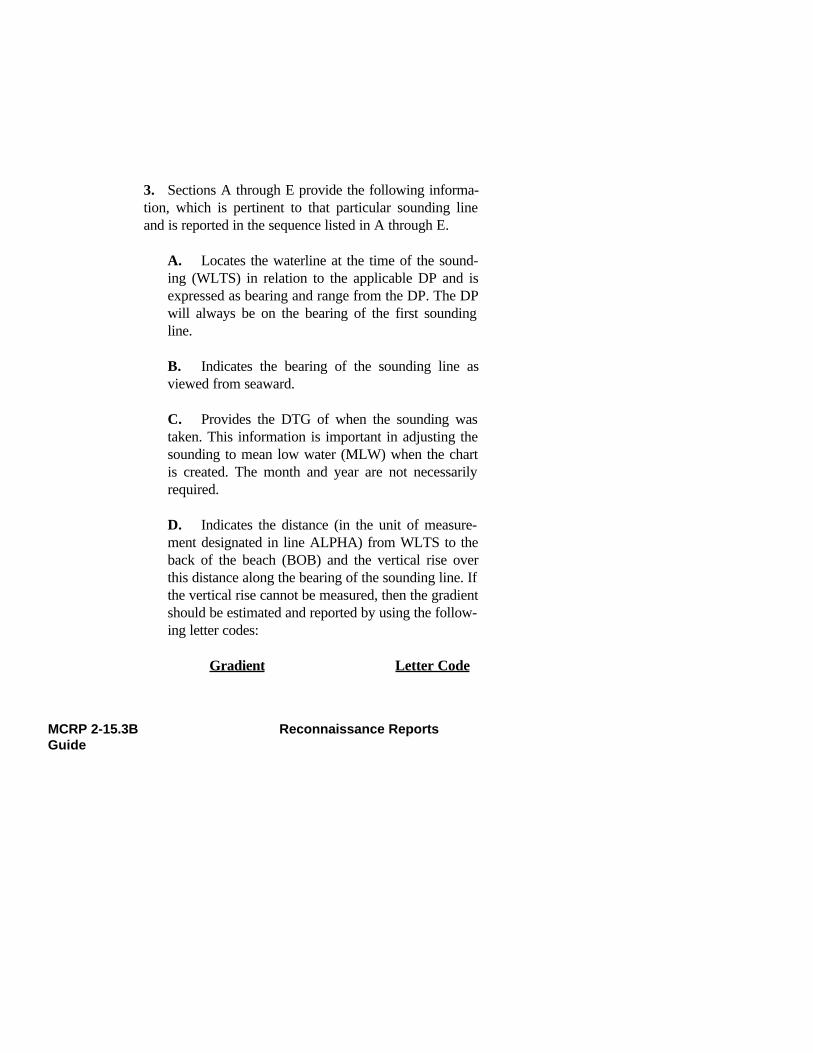
3. Sections A through E provide the following informa-tion, which is pertinent to that particular sounding lineand is reported in the sequence listed in A through E.
A. Locates the waterline at the time of the sound-ing (WLTS) in relation to the applicable DP and isexpressed as bearing and range from the DP. The DPwill always be on the bearing of the first soundingline.
B. Indicates the bearing of the sounding line asviewed from seaward.
C. Provides the DTG of when the sounding wastaken. This information is important in adjusting thesounding to mean low water (MLW) when the chartis created. The month and year are not necessarilyrequired.
D. Indicates the distance (in the unit of measure-ment designated in line ALPHA) from WLTS to theback of the beach (BOB) and the vertical rise overthis distance along the bearing of the sounding line. Ifthe vertical rise cannot be measured, then the gradientshould be estimated and reported by using the follow-ing letter codes:
Gradient Letter Code
MCRP 2-15.3B Reconnaissance ReportsGuide

Flat—flatter than 1:120 VMild—1:61 to 1:120 WGentle—1:31 to 1:60 XModerate—1:16 to 1:30 YSteep—steeper than 1:15 Z
E. Indicates each sounding to the nearest one-tenthmeter or one-half foot, followed by the bottom com-position, using the letter code in line HOTEL. Thesounding must be reported in linear sequence begin-ning from WLTS and working seaward.
4. For the second and subsequent lines, the report willshow similar data in the same sequence, except that underthe first subparagraph, WLTS A may beexpressed/plotted by using any of the following:
A. The bearing and distance from WLTS of the pre-vious sounding line.
-or-
B. The bearing and distance from the DP being usedfor that sounding line.
-or-
C. If any sounding line is to be based on a new DP,then the same procedure as in FOXTROT 1A is to beused.
40 CONBEREPMCRP 2-15.3B Reconnaissance Reports

GOLF Underwater Obstacles. This paragraph is used toindicate underwater obstacles relative to sounding linesby naming the type of obstacle, its location (use soundingline designation and distance from WLTS), depth of wa-ter over the obstacle, and its estimated size.
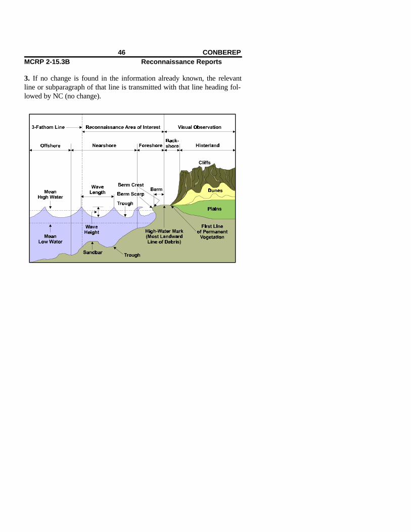
HOTEL Beach Composition. This is a general description relatedto the beach as a whole that is divided into two areas: theforeshore (from MLW to mean high water (MHW)) andthe backshore (MHW to BOB). An assessment of under-water composition is provided, as required. The followingletter codes should be used:
Beach Composition Letter Code
Mud AClay BSand (up to pinhead size) C Gravel/shingle (up to top-of-thumb size) DPebbles (up to clenched fist size) ECobbles (up to human head size) FBoulders (larger than human head size) GCoral HOther (describe briefly in this line) J
If there is a marked variation in composition along thebeach, this is to be reported, using code, by reference to designated sounding line numbers; for example, HOTEL1.A08 to B02 E means that the foreshore from soundingline A08 to sounding line B02 is now composed ofpebbles.
MCRP 2-15.3B Reconnaissance ReportsGuide
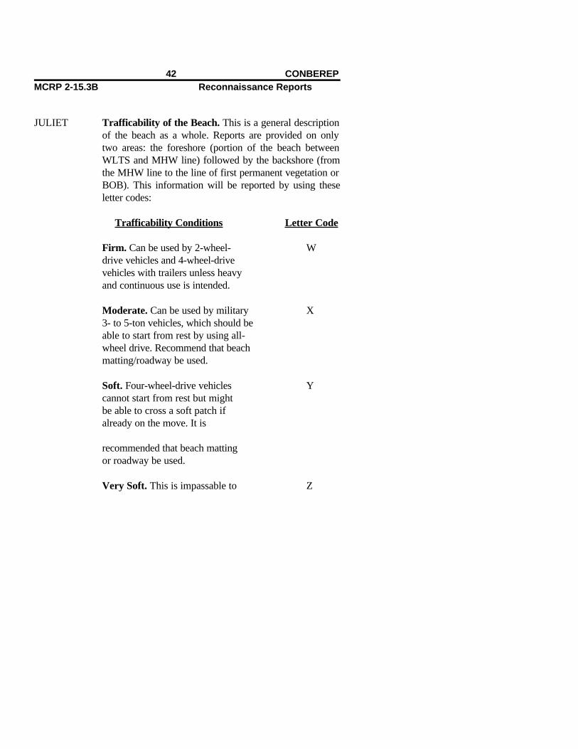
JULIET Trafficability of the Beach. This is a general descriptionof the beach as a whole. Reports are provided on onlytwo areas: the foreshore (portion of the beach betweenWLTS and MHW line) followed by the backshore (fromthe MHW line to the line of first permanent vegetation orBOB). This information will be reported by using theseletter codes:
Trafficability Conditions Letter Code
Firm. Can be used by 2-wheel- Wdrive vehicles and 4-wheel-drivevehicles with trailers unless heavyand continuous use is intended.
Moderate. Can be used by military X3- to 5-ton vehicles, which should beable to start from rest by using all-wheel drive. Recommend that beachmatting/roadway be used.
Soft. Four-wheel-drive vehicles Ycannot start from rest but mightbe able to cross a soft patch ifalready on the move. It is
recommended that beach mattingor roadway be used.
Very Soft. This is impassable to Z
42 CONBEREPMCRP 2-15.3B Reconnaissance Reports

wheeled vehicles. Tracked vehicles may experience difficulty. Beachmatting/roadway is required.
Note: If there is a marked difference in trafficability alongthe beach, this is to be reported in a similar manner toline HOTEL above. Foreshore trafficability can only beassessed above the WLTS. It must be clearly understoodthat a correct assessment of trafficability cannot be guar-anteed, bearing in mind the conditions under which theteam may be working. Allowances must be made for ahigh degree of error. The only way to get an accurate as-sessment of beach trafficability is to have the team returnwith soil samples that are properly cataloged andrecorded.
KILO Exits. This is a description of any new exits or exits thathave changed from the latest intelligence estimates. Eachbeach exit is listed and described individually. The exitsare described by reporting the grid reference where theexit meets the BOB, followed by a description using thefollowing letter codes:
Type of Beach Exit Letter Code
Infantry. If the exit is usable by Ainfantry only, then the width of the exit is reported following the lettercode.
Tracked Vehicles. If the exit is B
MCRP 2-15.3B Reconnaissance ReportsGuide

usable by both infantry and tracked vehicles, then the width is reported followed by the appropriate trafficabilitycode used in line JULIET of this reportand the width of the exit.
Wheeled Vehicles. If the exit is C usable by infantry and wheeled vehicles, then the information is reported in the same sequence as for tracked vehicles in this line.
Unusable. This denotes exits that were Dthought to be usable before theinsertion of the team and a properreconnaissance that determined such information to be incorrect.
LIMA Position of the Beach Reconnaissance Patrols. The po-sition of an amphibious reconnaissance team (ART) aftercompleting its reconnaissance is given as a six-digit refer-ence or by some other previously arranged system of ref-erence. This information needs to be transmitted only ifthe ART will be staying in the vicinity of the beach whilethe assault is taking place or in some other way may af-fect the scheme of maneuver or fire support plan of theunit being supported.
MIKE Enemy. If the enemy has been observed or contacted, thisinformation is reported sequentially by using the follow-ing format:
44 CONBEREPMCRP 2-15.3B Reconnaissance Reports
1st. Grid reference of the enemy position/contact.
2nd. Strength/number of the enemy observed.
3rd. Weapons, especially any weapons or weaponssystems that could jeopardize the accomplishment ofthe amphibious operation.
Note: A SPOTREP/SALUTE report should normally betransmitted separately to clarify and more accurately de-scribe all enemy sightings and possible intentions.
NOVEMBER Remarks. Any additional information relevant to this re-port can be included here. Any essential elements of in-formation (EEIs) or other information requirements(OIRs) should be stated in the patrol’s operation order(OPORD) and will come down from CATF and com-mander, landing force (CLF).
Notes:
1. The term right or left always refers to the beach area as viewed fromseaward, as if the reader of the report were a coxswain in a boat cominginto the beach.
2. One knot equals approximately 31 meters or 100 feet per minute ofmovement. If the recorder were to toss an object into the water and meas-ure how far it has moved in that current in one minute, he should be ableto approximate the speed and the direction of that current.
MCRP 2-15.3B Reconnaissance ReportsGuide
3. If no change is found in the information already known, the relevantline or subparagraph of that line is transmitted with that line heading fol-lowed by NC (no change).
46 CONBEREPMCRP 2-15.3B Reconnaissance Reports

CONBEREP Worksheet
_______________ this is _______________(receiver) (sender)
CONBEREP - (serial number followed by code name and map sheet detailsas required)
ALPHA -
BRAVO -
CHARLIE -
DELTA - DP A -
DP B -
DP C -
ECHO -
FOXTROT - (F1)
MCRP 2-15.3B Reconnaissance ReportsGuide

(F2)
(F3)
(F4)
(F5)
(F6)
(F7)
(F8)
(F9)
(F10)
GOLF -
HOTEL - (H1)
(H2)
(H3)
JULIET - (J1)
(J2)
KILO -
48 CONBEREPMCRP 2-15.3B Reconnaissance Reports
LIMA -
MIKE -
NOVEMBER (remarks) -
DTG -
MCRP 2-15.3B Reconnaissance ReportsGuide

Contact Report (CONTACREP)
The CONTACREP, although not a standard report, is very useful forbriefly and concisely reporting any enemy contact. It consolidates the mostimportant IRs of the SITREP and the CASREP without wasting largeamounts of transmission time in a rapidly evolving and tenuous situation.In such situations, the reconnaissance patrol leader must be able to con-centrate all of his attention on resolving his patrol’s present situation andcontinuing the mission, working out a plan to extract his patrol to a securearea, or effecting the evasion and escape (E&E) plan.
C—Call sign. “(Receiver’s call sign) this is (originator’s call sign).”
O—Occurrence. Describes the type of contact/what has happened.
N—Needs. States medical evacuation, emergency extraction, immedi-ate suppression, reinforcement, resupply, and other needs.
T—Time/Location. Indicates at what time the contact took place andwhere. These coordinates do not need to be encrypted/shackled.
A—Actions Taken. Describes what the patrol has done since the con-tact was made, for example, broken contact, E&E, or so on.
C—Casualties. Reports friendly KIAs/WIAs and transmits kill num-bers from the warning order/kill sheet to assist the medical evacuationwhen needed.
Note: The person transmitting the CONTACREP must be prepared toauthenticate if operating over an uncovered net. This is especially the
MCRP 2-15.3B Reconnaissance ReportsGuide

case if the patrol is requesting emergency extraction, immediate suppres-sion, medical evacuation, or reinforcement.
52 CONTACREPMCRP 2-15.3B Reconnaissance Reports Guide

CONTACREP Worksheet
Contact — Contact — Contact ___________ this is____________ (receiver) (sender)
Occurrence -
Needs -
Time/location -
Action taken -
MCRP 2-15.3B Reconnaissance ReportsGuide

Casualties -
Remarks -
DTG -
54 CONTACREPMCRP 2-15.3B Reconnaissance Reports Guide
River/Estuary Report (DELTAREP)
Begin the report with the subject line of the message and the serial numberor code name, followed by map sheet details as required.
ALPHA Units of Measurement. See the table on page 3.
BRAVO Location. This line provides grid references of the begin-ning and end of the section of the river/estuary actuallyreconnoitered by the team.
CHARLIE Main Channel. This information is reported in the fol-lowing numbered sequence:
1. Location. The grid reference of the entrance to themain channel is provided.
2. Seaward Approach. The bearing from seaward ofthe approaches to the main channel (using the angularunit of measurement designated in line ALPHA) is pro-vided. If this information is already known and has notchanged, report NC. If this information does not apply tothis mission, then report NIL. If the team was unable todetermine this information because of the enemy situationor other considerations, they will report NAR (not able torecord) and explain the reason in line KILO (remarks) ofthis report.
3. Reference Points. The entrance to the main channelmay be fixed by means of transits and/or bearings ofprominent features that can be observed from seaward.
MCRP 2-15.3B Reconnaissance ReportsGuide

These features must also be recognizable on a map orchart (these reference points may be precoordinated andassigned code names or other designations before theteam is inserted). This information is reported in the fol-lowing sequence.
A. Prominent Features. This includes the descrip-tion and location of the feature followed by its bear-ing from seaward at the entrance to the main channel.If more than one feature is being used to get a resec-tion for the channel entrance, then the features arenumbered sequentially and described individually.They are numbered 1, 2, 3, and so on.
- or -
B. Transits. Transits are two points that are recog-nizable when viewed from seaward and can be lo-cated on a map/chart. Transits will line up one behindthe other when the boat is on the correct azimuth tothe entrance to the main channel. Transits are re-ported by giving a brief description of each point andits location so that it can be plotted on a map/chart. Ifmore than one set of transits will be used to locate thechannel entrance, they will be reported individuallyand numbered sequentially 1, 2, 3, and so on.
DELTA Navigation Aids. A local system of buoys (if any) ormarkers placed by the teams is reported by using thefollowing code:
Type of Navigation Aid Number Code
56 DELTAREPMCRP 2-15.3B Reconnaissance Reports Guide

Starboard hand buoys (shape and 1color)
Port hand buoys (shape and color) 2Team-placed buoys/markers 3
(description and location)
ECHO Hazards. These are reported in numbered sequence fol-lowed by the letter code describing the type of hazardthen by the grid reference location of the hazard(s). Thefollowing letter codes are used to describe the type ofhazard being reported:
Type of Hazard Letter Code
Sandbars AWrecks BRocks CTidal races DNets (describe) EBridges (report overhead clearance) FOther (describe as required) G
FOXTROT Navigational Limits. This line provides the highest pointupstream in the main channel with the following depth atlow water; this is a six- or eight-digit reference followedby the following letter codes:
Navigational Limits Letter Code
MCRP 2-15.3B Reconnaissance ReportsGuide

2 meters A1 meter B1/2 meter C
GOLF Beaching/Landing Points and Exits. This information isreported sequentially and in the following format:
1st. Grid reference of the beaching/landing point.
2nd. Type of landing craft that can use the landingpoint, indicated by the following letter code:
Type of Landing Craft Letter Code
Landing craft, medium/utility ALanding craft, personnel BShallow boats with outboard engines COther craft as required D
3rd. Overall trafficability of the beaching point andexit, reported by using the following number code:
Trafficability Number Code
Firm. Can be used by 12-wheel-drive vehiclesor 4-wheel-drive vehicleswith trailers unless heavy,continuous use is intended.
Moderate. Can be used by 2
58 DELTAREPMCRP 2-15.3B Reconnaissance Reports Guide
3- or 5-ton vehicles, which should be able to start fromrest by using all-wheel drive.Recommend using beachmatting/roadway.
Soft. Four-wheel-drive vehicles 3cannot start from rest butmight be able to cross a softpatch if already on the move. Recommend using beachmatting/roadway.
Very Soft. Impassable to 4wheeled vehicles; trackedvehicles may experiencedifficulty. Use of beachmatting/roadway is required.
Notes:
1. If the landing point or its exits are unsuitable forany vehicles, the letter code NIL is reported.
2. If the team confirms that information on sus-pected beaching/landing points is correct, the teamwill report NC.
4th. Width of exit, reported in the unit of measure-ment designated in line ALPHA.
MCRP 2-15.3B Reconnaissance ReportsGuide
HOTEL Current. The speed of the current/tidal stream should beindicated in the unit of measurement designated in lineALPHA. The information is reported in the followingsequence:
1st. Velocity of the water.
2nd. Direction in which the current is flowing (usethe letter that would indicate the cardinal direction ofthe water flow at the time of sounding (e.g., N(north), NE (northeast), SW (southwest), etc.).
3rd. DTG and location (grid reference) of thesounding.
Note: Several of these soundings may be required atdifferent locations in the waterway to more accu-rately represent the current as the water flows towardits mouth. Also, several soundings may be required atthe entrance to the waterway if tidal conditions arepresent.
JULIET Texture of the River Bed. This information is reportedin the following sequence:
1st. Grid reference of where the bottom sample wastaken.
2nd. Letter code indicating the composition of theriver bottom:
River Bottom Composition Letter Code
60 DELTAREPMCRP 2-15.3B Reconnaissance Reports Guide

Mud ASand BRock CShingles DVegetation EOther (briefly describe) F
KILO Remarks. This line provides any other information thathas not been covered in the report and that could have animpact on the riverine operation to be conducted. Thistype of information should be covered in the IRs.
Note: If the patrol is to be extracted before the start of theoperation, they should bring back soil samples of the dif-ferent key portions of the area that the team reconnoi-tered. These need to be properly labeled and recorded. Inthis manner, the unit being supported can more accuratelyestimate the type of conditions under which it will beoperating.
MCRP 2-15.3B Reconnaissance ReportsGuide

DELTAREP Worksheet
_______________ this is _______________(receiver) (sender)
DELTAREP - (serial number followed by code name and map sheet de-tails as required)
ALPHA -
BRAVO -
CHARLIE - (C1)
(C2)
(C3)
DELTA -
ECHO -
FOXTROT - ALPHA
BRAVO
CHARLIE
GOLF -
HOTEL -
62 DELTAREPMCRP 2-15.3B Reconnaissance Reports Guide

JULIET -
KILO (remarks) -
DTG -
MCRP 2-15.3B Reconnaissance ReportsGuide

Drop Zone Report (DZREP)
Begin the report with the subject line of the message, the serial number,and/or the drop zone code name or code identification letter (determinedand coordinated before the team is inserted), followed by map sheet detailsas required.
ALPHA Units of Measurement. See the table on page 3.
BRAVO Time. This line provides the DTG that the reconnais-sance was completed.
CHARLIE Grid Reference of Point of Impact. The position of theintended point of impact is reported by grid reference.The point of impact is the selected point at which it is in-tended for the first parachute from the drop run to makeimpact with the ground.
DELTA Height. The height AMSL of the point of impact and theheight AMSL of the highest point of the drop zone are re-ported (in that sequence) by using the unit of measure-ment designated in line ALPHA.
ECHO Extremities of the Drop Zone. Grid references of the ex-tremities of the drop zone are provided.
FOXTROT Description. The drop zone is described in the followingsequence by using the units of measurement designated inline ALPHA.
MCRP 2-15.3B Reconnaissance ReportsGuide

1st. Usable length.
2nd. Usable width.
3rd. Drop zone gradient.
Notes:
1. The gradient of the ground is expressed as a ratio.
2. Slope within the drop zone should preferably be lessthan 1:10 and without surface irregularities.
3. Slopes steeper than 1:3 are unusable.
GOLF Surface. A description of the surface of the drop zoneshould be given in two parts by using the following codes:
1st
Surface Hardness of the Number CodeDrop Zone
Hard. Can be used by 2- 1wheel-drive vehiclesor 4-wheel-drive vehicleswith trailers unless heavyand continuous use is intended.
Moderate. Can be used by 3- 2and 4-ton vehicles, which shouldbe able to start from rest by using
66 DZREP

all-wheel drive.
Soft. Four-wheel-drive vehicles 3cannot start from rest but mightcross if already on the move.
2nd
Nature of the Ground in the Drop Zone Letter Code
Sand AGrass BScrub CSnow DIce EMarsh FOther (describe briefly) G
HOTEL Drop Zone Obstructions. This information is reported inthe following sequence by using the following code:
1st. Bearing of obstacle from the point of impact.
2nd. Type of obstacle, using the following letter code.
3rd. Distance of the obstacle from the point ofimpact.
MCRP 2-15.3B Reconnaissance ReportsGuide

Note: Use the units of measurement recorded in line AL-PHA of this report.
Type of Obstruction Letter Code
Rocks ABuildings BFences CHedges DTrees EPoles FPylons/high-tension wires GWater obstacles (be specific) HDitches JCraters KOther (specify in this line) L
JULIET Suitability and Type of Drop Zone. This line indicates,by the following numerical code, whether the drop zone issuitable for the following:
Type of Drop Number Code
Personnel drop 1Platform drop 2Supply drop 3Other (specify) 4
68 DZREP

Notes:
1. Characteristics of Personnel Drop Zones:
A. Surface. A flat, resilient surface without obstruc-tions is technically the most suitable for a troop dropzone.
B. Obstacles. Obstacles preventing the use of adrop zone are built-up areas; high-tension wires;cliffs; ravines; and normally rivers, ponds, and lakesnear the intended drop zone. However, jumps onlakes or in any large body of water can be carried outby specially equipped and trained personnel.
C. Other Areas. If considered operationally neces-sary, drops may be made in wooded or forested areas,mountains, or lakes by using specially equipped andtrained personnel.
2. Special Considerations for a Cargo Drop Zone.The required characteristics are similar to those for per-sonnel drop zones. In addition, they should be accessibleto vehicles or at least crossed by paths to simplify the col-lection of the equipment and supplies. Dropping suppliesover water should be considered only under specialcircumstances.
3. Special Drop Methods. Use of methods such asultra-low-level-approach (ULLA) will require specialist
MCRP 2-15.3B Reconnaissance ReportsGuide
representation on the team or at least special training inthe technique to be employed.
KILO Vehicle Exit Points. This line reports, by grid reference,possible vehicle exit points from the drop zone to prede-termined line(s) of communications.
LIMA Drop Zone Markings. All drop zone marking/locationaids are to be prebriefed, and only variations from thebrief need to be reported. When smoke is being used as adrop zone location aid, the team should indicate whensmoke is being released but not the color. The pilot of thelead aircraft should read back the color seen, and theteam should confirm that the correct color has been spot-ted. A no drop signal should also be prebriefed before theteam is inserted.
MIKE Recommended Direction of Run In/Run Out Tracks.This line reports recommended tracks for the aircraft runin/run out; these are expressed in the unit of measurementlisted in line ALPHA. This information is transmitted inthe following sequence:
1st. Primary run in/primary run out track.
2nd. Alternate run in/alternate run out track.
NOVEMBER Target Approach Point (TAP). The recommended TAPshould be reported only if one is observed that is
70 DZREP
more suitable than that previously selected and briefed. Ifapplicable, report in the following sequence:
1st. Primary TAP.
2nd. Alternate TAP.
PAPA Obstacles and Hazards on the Run In/Run OutTracks. This line reports major obstacles in the vicinityof the drop zone and along recommended run in/run outtracks. If unable to recommend run in/run out tracks, allmajor obstacles and hazards in the area are reported byusing the following letter codes and sequence:
Type of Obstacles/Hazards Letter Code
High-tension wires ABuilt-up areas BCliffs CRavines DWater obstacles (specify what type) EWooded areas FMasts, chimneys, or pylons (specify) GHigh ground HOther (describe briefly) J
MCRP 2-15.3B Reconnaissance ReportsGuide

The following is the sequence that will be used to reportthis information:
1st. Bearing from the impact point (IP).
2nd. Type of obstacle (using the letter code).
3rd. Distance from IP.
4th. Height of obstacle (using unit of measurementdesignated in line ALPHA).
Note: If it has not been possible to fully observe the areabetween the TAP and the drop zone, the suffix N (not ob-served) should be added to the end of this line.
QUEBEC Ground-Air Communications. This line includes pri-mary and alternate ground-air communications line num-bers if they are different from the precoordinatedfrequencies. The changes will be reported in the followingorder:
1st. Primary frequency.
2nd. Alternate frequency.
ROMEO Enemy. Known enemy positions, strengths, and weaponsare to be reported sequentially in the following format:
1st. Grid reference of the enemy position.
72 DZREP

2nd. Strength/number of enemy observed.
3rd. Weapons, especially any weapons systems thatcould jeopardize the accomplishment of the airborneoperation.
Note: A SPOTREP/SALUTE report should normally betransmitted to clarify and more accurately describe all en-emy sightings and intentions.
SIERRA Weather. The weather is reported at the time that the re-connaissance is completed and as required and briefed be-fore the team is inserted. This information will bereported in the following sequence:
1st. Wind direction (from which the wind is blowing)and estimated speed (using units of measurement des-ignated in line ALPHA of the report).
2nd. Cloud cover—the portion of the sky that is ob-scured, in eighths, and the estimated base above thedrop zone.
3rd. Visibility.
4th. Temperature.
TANGO Remarks. Other information that is not covered as partof the report but that could prove vital to the accom-plishment of the supported unit’s scheme of maneuver is
MCRP 2-15.3B Reconnaissance ReportsGuide
included. This information should be covered as part ofthe patrol’s IRs.
Notes:
1. Lines from the report need not be transmitted whenthe information is either already known or not required.NC (no change) can be used to confirm information al-ready prebriefed in the reconnaissance brief.
2. The following documents are relevant to determiningthe precise parameters for size and marking of the zone.
A. Standardization Agreement (STANAG) 3570,Drop Zones and Extraction Zones—Criteria andMarking.
B. The appropriate national standing orders, manu-als, or instructions on drop zones.
74 DZREP
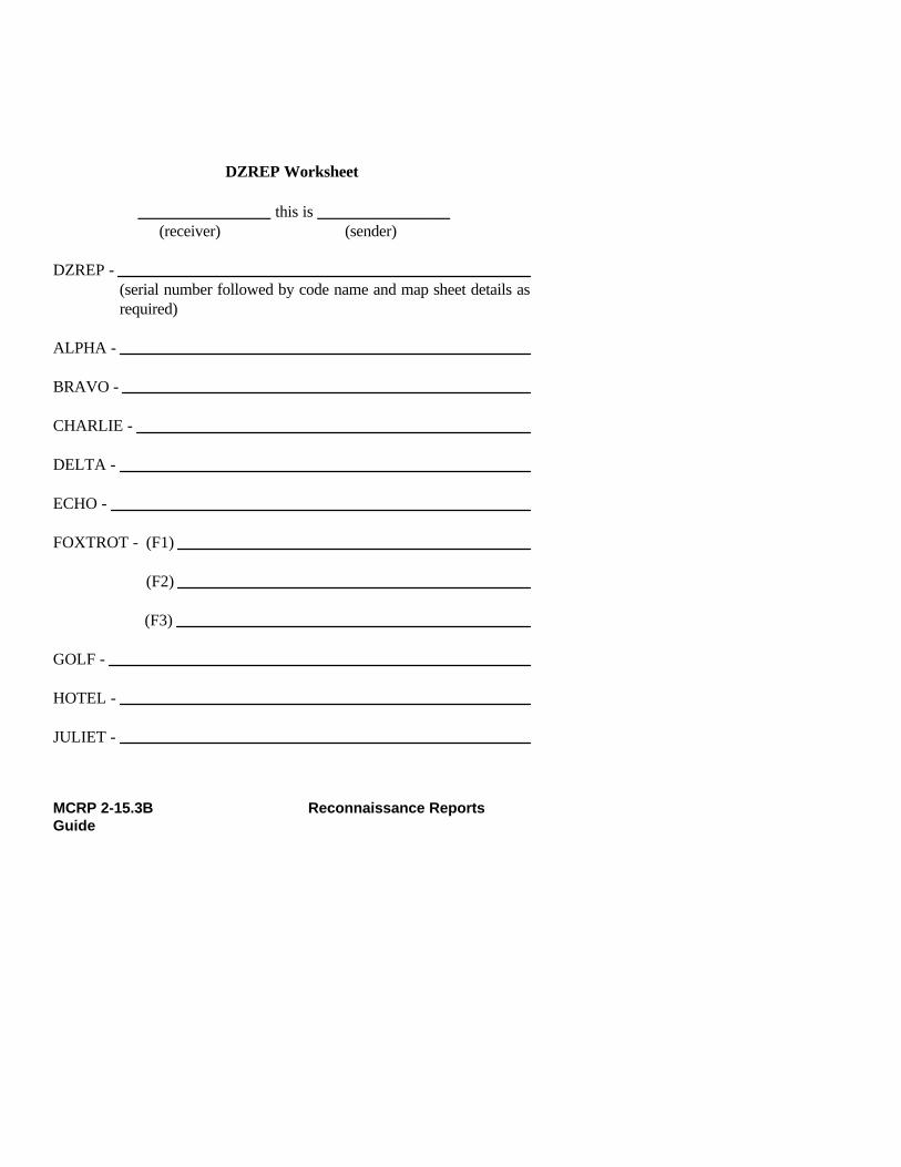
DZREP Worksheet
_______________ this is _______________(receiver) (sender)
DZREP - (serial number followed by code name and map sheet details asrequired)
ALPHA -
BRAVO -
CHARLIE -
DELTA -
ECHO -
FOXTROT - (F1)
(F2)
(F3)
GOLF -
HOTEL -
JULIET -
MCRP 2-15.3B Reconnaissance ReportsGuide

KILO -
LIMA -
MIKE - (M1)
(M2)
NOVEMBER - (N1)
(N2)
PAPA -
QUEBEC -
ROMEO -
SIERRA - (S1)
(S2)
(S3)
(S4)
TANGO (remarks) -
DTG -
76 DZREP
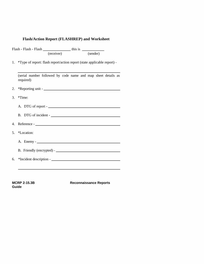
Flash/Action Report (FLASHREP) and Worksheet
Flash - Flash - Flash _______________ this is ____________ (receiver) (sender)
1. *Type of report: flash report/action report (state applicable report) -
(serial number followed by code name and map sheet details asrequired)
2. *Reporting unit -
3. *Time:
A. DTG of report -
B. DTG of incident -
4. Reference -
5. *Location:
A. Enemy -
B. Friendly (encrypted) -
6. *Incident description -
MCRP 2-15.3B Reconnaissance ReportsGuide

7. *Action taken/being taken by the unit initiating the report -
8. Friendly casualties (encrypted):
A. KIA -
B. WIA-
C. MIA-
9. Enemy casualties:
A. KIA -
B. KIA probable -
C. Prisoners of war (POWs) -
D. Suspects -
E. Other indigenous captives -
10. Captured enemy weapons, equipment, and documents -
78 FLASHREPMCRP 2-15.3B Reconnaissance Reports
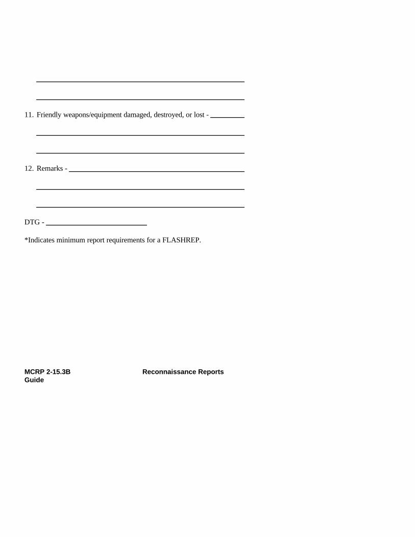
11. Friendly weapons/equipment damaged, destroyed, or lost -
12. Remarks -
DTG -
*Indicates minimum report requirements for a FLASHREP.
MCRP 2-15.3B Reconnaissance ReportsGuide
Frequency Interference Report (FIRREP) and Worksheet
All incidents will be reported via secure means as soon as possible.
_______________ this is _______________ (receiver) (sender)
FIRREP - (serial number followed by code name and map sheet details asrequired)
1. Time -
2. Unit -
3. Frequency -
4. Type (meaconing/intrusion/jamming/interference) -
5. Remarks -
DTG -
MCRP 2-15.3B Reconnaissance Reports Guide81

River Ford Report (FORDREP)
Begin the report with the subject line followed by the serial number andmap sheet details as required.
ALPHA Units of Measurement. See the table on page 3.
BRAVO DTG. This line reports the DTG of when the ford recon-naissance was completed.
CHARLIE Location. This line provides the grid reference of thefording site followed by engineer classification, if known.
DELTA Capabilities. The type of traffic that the ford is capableof supporting is reported by using the following numeri-cal code:
Type of Traffic Number Code
Light infantry 1Light military vehicles 2
(no snorkeling gear)Light military vehicles 3
(with snorkeling gear)Swimming vehicles 4Other 5
ECHO Length of Ford. A measurement of the distance from en-trance point to exit point is reported in the unit of meas-urement designated in line ALPHA.
MCRP 2-15.3B Reconnaissance ReportsGuide

FOXTROT Depth and Velocity of Running Water. These are re-ported in the unit of measurement designated in line AL-PHA. This information will be recorded and transmittedin the following sequence:
1st. Depth of the water at the ford site.
2nd. Velocity of the water at the ford site.
3rd. DTG of the sounding.
Climatic, tidal, or other considerations may dictate thatseveral soundings are required for the supported unit todetermine the suitability of the ford site to support theirscheme of maneuver. If more than one sounding is re-quired, then the soundings will be reported sequentiallyand individually.
Example: F1.3/2 042315HF2.6/7 050340H
GOLF Ford Bottom Composition. This information is reportedby using the following numerical code:
Bottom Composition Number Code
Mud 1Clay 2Sand 3Rock 4Gravel 5Artificial pavement 6
84 FORDREP

Other (followed by description) 7
HOTEL Gradient of the Ford’s Approach and Exit. This infor-mation is reported, using a ratio to represent the percent-age of slope, in the following sequence: the slope of theford approach followed by the percentage of slope for theford exit.
JULIET Composition of the Ford’s Approach and Exit. This in-formation is reported by using the same number codeused in line GOLF and in the same sequence as in lineHOTEL.
Example: J1.5J2.4
In this example, the ford approach is composed of gravel,and the ford exit is composed of rock.
KILO Usable Width of Approach and Exit. This informationis reported in the same sequence as lines HOTEL and JU-LIET, using the unit of measurement designated in lineALPHA.
LIMA Remarks. Any other information is reported that could bevital to the scheme of maneuver of the unit that the ARTis supporting and should be designated in the patrol’sIRs.
MCRP 2-15.3B Reconnaissance ReportsGuide

River FORDREP Worksheet
__________________ this is _________________(receiver) (sender)
FORDREP - (serial number followed by code name and map sheet details as required)
ALPHA -
BRAVO -
CHARLIE -
DELTA -
ECHO -
FOXTROT -
GOLF -
HOTEL - (H1)
(H2)
JULIET - (J1)
(J2)
KILO - (K1)
86 FORDREP

(K2)
LIMA (remarks) -
DTG -
MCRP 2-15.3B Reconnaissance ReportsGuide

Helicopter Landing Site Report (HELLSREP)
Begin the report with the subject line and the serial number, followed bythe helicopter landing site designation (coordinated before the insertion ofthe team) and map sheet details as required.
ALPHA Units of Measurement. See the table on page 3.
BRAVO DTG. This line provides the DTG of when the heli-copter landing zone reconnaissance was completed.
CHARLIE Location. Location is reported as grid references (orby another precoordinated method of position location)of the extremities of the landing site. It is prefixed bythe two-letter grid zone designator when there is anypossibility of uncertainty about the map sheet(s) onwhich the team is reporting.
DELTA Orientation of the Long Axis of the Landing Site.This is reported by using the unit of measurement des-ignated in line ALPHA of the report.
ECHO Number and Size of the Landing Points. Sizes of thelanding points are reported as L (large), M (medium),or S (small), as briefed in STANAG 3570. This infor-mation should be reported in the following sequence:
1st. The number of each size of landing points.
2nd. The code for the type of landing points beingreported.
MCRP 2-15.3B Reconnaissance ReportsGuide
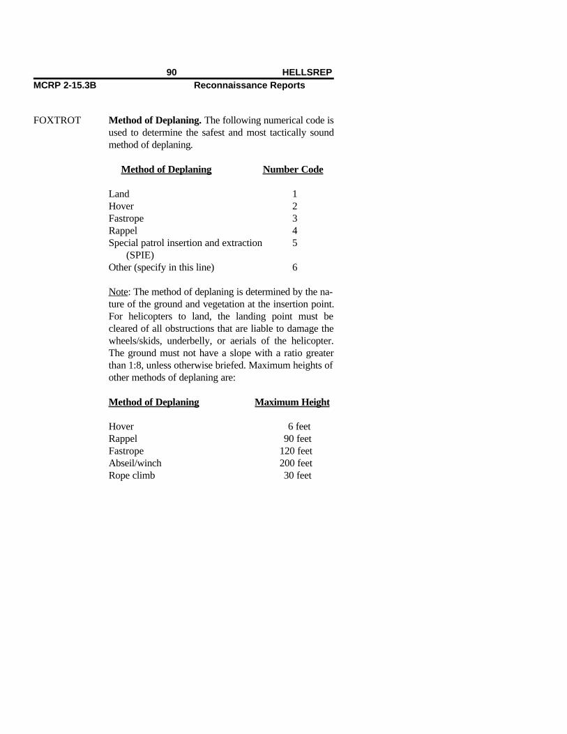
FOXTROT Method of Deplaning. The following numerical code isused to determine the safest and most tactically soundmethod of deplaning.
Method of Deplaning Number Code
Land 1Hover 2Fastrope 3Rappel 4Special patrol insertion and extraction 5
(SPIE)Other (specify in this line) 6
Note: The method of deplaning is determined by the na-ture of the ground and vegetation at the insertion point.For helicopters to land, the landing point must becleared of all obstructions that are liable to damage thewheels/skids, underbelly, or aerials of the helicopter.The ground must not have a slope with a ratio greaterthan 1:8, unless otherwise briefed. Maximum heights ofother methods of deplaning are:
Method of Deplaning Maximum Height
Hover 6 feetRappel 90 feetFastrope 120 feetAbseil/winch 200 feetRope climb 30 feet
90 HELLSREPMCRP 2-15.3B Reconnaissance Reports

GOLF Landing Site Surface. The information in this line isreported in three parts by using the following sequenceand letter/numerical codes:
1st. Trafficability of the landing site:
Trafficability of Number Codethe Landing Site
Hard. The surface can 1support the helicopter and be used by 2-wheel-drive vehicles or 4-wheel-drive vehicles withtrailers unless heavy andcontinuous use is intended.
Moderate. The surface can 2support the helicopter and beused by 3- or 5-ton vehicles,which should be able to startfrom rest when using all-wheel drive.
Soft. The helicopter can land, 3but if the surface is wet it couldcause suction to form on thewheels/skids of the helicopter.Four-wheel-drive vehicles cannotstart from rest but should beable to cross the landing site if
MCRP 2-15.3B Reconnaissance ReportsGuide

already on the move.
2nd. Type of landing surface:
Type of Landing Surface Letter Code
Sand AGrass BScrub CSnow DIce EMarsh FDust GPaddy HOther (specify and describe) J
Note: When the ground is covered with snow, alsoreport the subsurface of the landing site.
3rd. Ability of the surface of the landing site to re-circulate. Whether or not the surface will recircu-late is reported by marking Y (yes) or N (no).Recirculation is the effect of the downwash fromthe helicopter, which is liable to pick up sand, dust,or snow and blow it through the rotors, thereby se-verely reducing visibility for the pilot. This willhave an effect on the frequency at which the heli-copters can safely land and take off.
HOTEL 1. Direction of Approach
92 HELLSREPMCRP 2-15.3B Reconnaissance Reports
2. Direction of Egress
Notes:
1. The approach and egress azimuths are reported inthe unit of measurement designated in line ALPHA.Whenever possible, these directions are into the wind.Oftentimes, the enemy situation, orientation of the longaxis of the landing site, and obstacles surrounding thelanding site will dictate an alternate direction.
2. Direction of approach is not necessarily the sameas the direction of landing, which will normally be de-cided by the pilots.
JULIET Wind Direction and Speed. Wind direction is re-ported as the direction from which the wind is coming;this is the same bearing that a helicopter would use tofly into the wind. These measurements are reported byusing the units of measurement designated in lineALPHA.
KILO Approach Angle. This is dictated by the height andproximity of surrounding obstacles. The normal maxi-mum angle should be no steeper than 1:10. Other limitsmay be prebriefed depending on the squadron’s stand-ing operating procedures and other considerations, suchas height AMSL and weight restrictions on thehelicopters.
MCRP 2-15.3B Reconnaissance ReportsGuide

LIMA Locations and Types of Recognition Aids. The loca-tions and types of landing site recognition aids that areprovided for any particular team must be prebriefedand coordinated with the aviation combat element andthe ground combat element before the insertion. Therecognition signals must be assigned letter codes simi-lar to those listed below. These should be changed andupdated before each operation as the situation dictates.The information in this line is reported in the followingsequence by using letter codes that are coordinated be-fore the operation and insertion.
1st. Grid reference of the recognition aids.
2nd. Type of recognition aid employed of thoseprecoordinated, for example:
Type of Recognition Aid Letter Code
Green smoke AYellow air panel BSignal mirror CStrobe light DOther (specify) E
MIKE Landing Aids. Landing aids that are provided for theteam must be coordinated, before the team is inserted,in the same manner that recognition signals must bepreplanned. These must be changed and updated beforeeach operation as the situation dictates. If no landingaids are to be used, report NIL.
94 HELLSREPMCRP 2-15.3B Reconnaissance Reports
Type of Landing Aid Number Code
Glide slope indicator 1Torch “T” 2Inverted “Y” 3Other (specify) 4
NOVEMBER Cloud Cover and Estimated Height Above theLanding Site. This is reported in the followingsequence:
1st. The percentage of the sky that is obscured byclouds. This information is reported in eighths(e.g., half cloud cover would be reported as 4;small patches would be reported as 1).
2nd. Estimated height of clouds above the landingsite. This is reported as the lowest cloud above thelanding site. This height is estimated and reportedin the unit of measurement designated in lineALPHA.
PAPA Visibility and Temperature. This information is re-ported in the following sequence by using the units ofmeasurement designated in line ALPHA.
1st. Visibility on the landing site.
2nd. Temperature on the landing site.
MCRP 2-15.3B Reconnaissance ReportsGuide
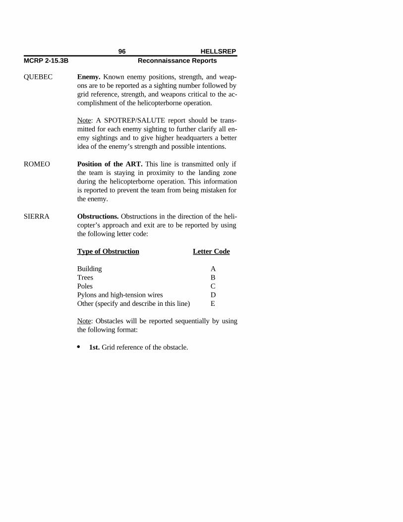
QUEBEC Enemy. Known enemy positions, strength, and weap-ons are to be reported as a sighting number followed bygrid reference, strength, and weapons critical to the ac-complishment of the helicopterborne operation.
Note: A SPOTREP/SALUTE report should be trans-mitted for each enemy sighting to further clarify all en-emy sightings and to give higher headquarters a betteridea of the enemy’s strength and possible intentions.
ROMEO Position of the ART. This line is transmitted only ifthe team is staying in proximity to the landing zoneduring the helicopterborne operation. This informationis reported to prevent the team from being mistaken forthe enemy.
SIERRA Obstructions. Obstructions in the direction of the heli-copter’s approach and exit are to be reported by usingthe following letter code:
Type of Obstruction Letter Code
Building ATrees BPoles CPylons and high-tension wires DOther (specify and describe in this line) E
Note: Obstacles will be reported sequentially by usingthe following format:
1st. Grid reference of the obstacle.
96 HELLSREPMCRP 2-15.3B Reconnaissance Reports
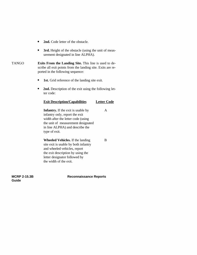
2nd. Code letter of the obstacle.
3rd. Height of the obstacle (using the unit of meas-urement designated in line ALPHA).
TANGO Exits From the Landing Site. This line is used to de-scribe all exit points from the landing site. Exits are re-ported in the following sequence:
1st. Grid reference of the landing site exit.
2nd. Description of the exit using the following let-ter code:
Exit Description/Capabilities Letter Code
Infantry. If the exit is usable by Ainfantry only, report the exitwidth after the letter code (usingthe unit of measurement designatedin line ALPHA) and describe the type of exit.
Wheeled Vehicles. If the landing Bsite exit is usable by both infantryand wheeled vehicles, reportthe exit description by using theletter designator followed bythe width of the exit.
MCRP 2-15.3B Reconnaissance ReportsGuide

Unusable. This letter code will Creport that the team was unableto locate any adequate exits fromthe landing site.
UNIFORM Restrictions to Troop Movement. Report the degreeof restriction of rapid troop deployment from the land-ing site. This information is reported by using the fol-lowing numerical code:
Degree of Troop Movement NumberRestrictions Code
Heavy restrictions to movement 1Moderate restrictions to movement 2Unrestricted movement 3
VICTOR Remarks. Other pertinent information, such as a land-mark to the landing zone, can be described in this para-graph, along with any other information as designatedin the patrol’s IRs.
Notes:
1. Any line from the report for which the information isnot known or not required should not be transmitted (toprevent the team from being located). NC (no change)is transmitted to confirm information given in the re-connaissance briefing.
98 HELLSREPMCRP 2-15.3B Reconnaissance Reports
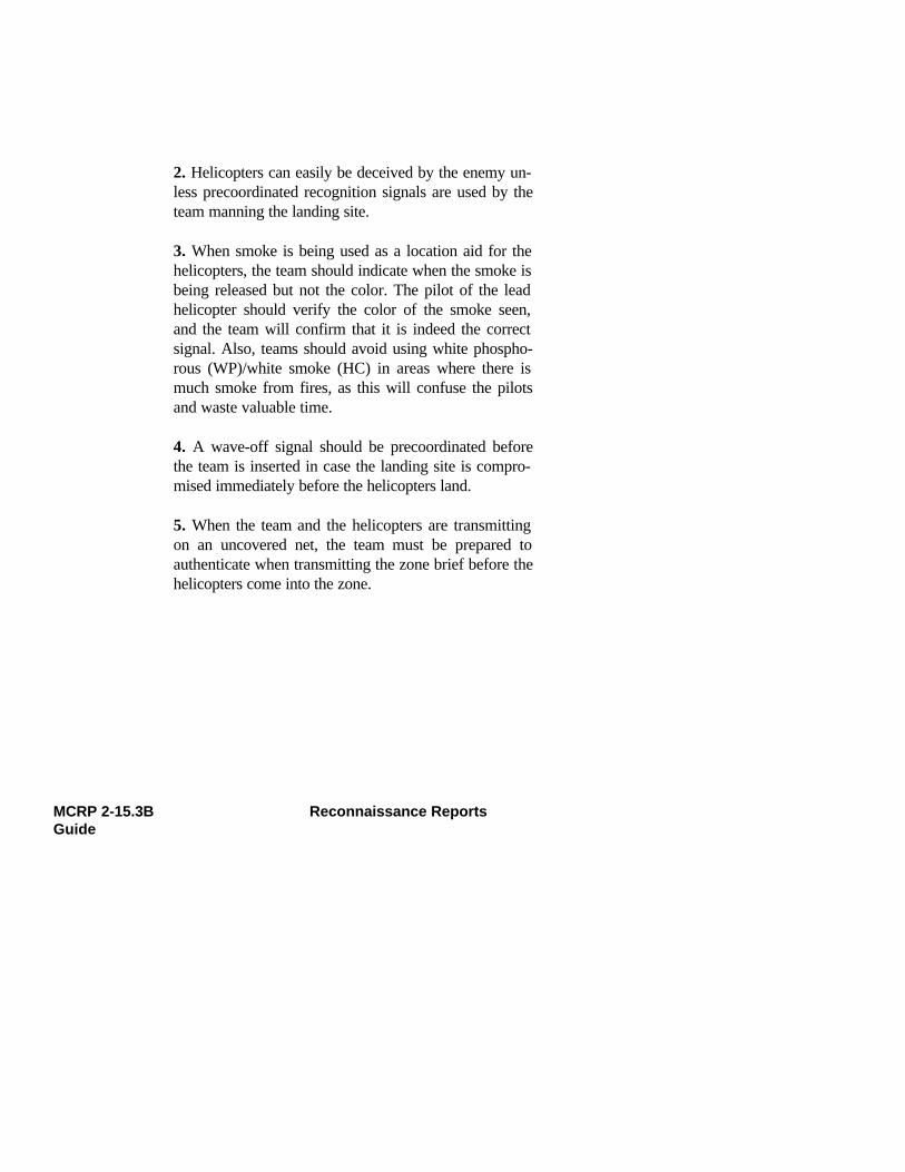
2. Helicopters can easily be deceived by the enemy un-less precoordinated recognition signals are used by theteam manning the landing site.
3. When smoke is being used as a location aid for thehelicopters, the team should indicate when the smoke isbeing released but not the color. The pilot of the leadhelicopter should verify the color of the smoke seen,and the team will confirm that it is indeed the correctsignal. Also, teams should avoid using white phospho-rous (WP)/white smoke (HC) in areas where there ismuch smoke from fires, as this will confuse the pilotsand waste valuable time. 4. A wave-off signal should be precoordinated beforethe team is inserted in case the landing site is compro-mised immediately before the helicopters land.
5. When the team and the helicopters are transmittingon an uncovered net, the team must be prepared toauthenticate when transmitting the zone brief before thehelicopters come into the zone.
MCRP 2-15.3B Reconnaissance ReportsGuide

HELLSREP Worksheet
_______________ this is _______________(receiver) (sender)
HELLSREP - (serial number followed by designation and map sheet details as required)
ALPHA -
BRAVO -
CHARLIE -
DELTA -
ECHO -
FOXTROT -
GOLF -
HOTEL - (H1)
(H2)
JULIET -
KILO -
LIMA -
100 HELLSREPMCRP 2-15.3B Reconnaissance Reports

MIKE -
NOVEMBER - (N1)
(N2)
PAPA -
QUEBEC -
ROMEO -
SIERRA -
TANGO -
UNIFORM -
VICTOR (remarks) -
DTG -
MCRP 2-15.3B Reconnaissance ReportsGuide

Meaconing, Intrusion, Jamming, and Interference Report (MIJIREP) and Worksheet
______________ this is _______________(receiver) (sender)
MIJIREP - (serial number followed by code name and map sheet details as required)
All incidents will be reported via secure means as soon as possible.
1. Type of report -
A. Meaconing. Transmission of false navigation signals.
B. Intrusion. Bogus stations, imitative deception.
C. Jamming. Deliberate disruption of friendly communications.
D. Interference. Natural or manmade obstructions that causedifficulty in receiving radio signals.
2. Effects on station -
3. Station location -
4. Frequency or channel affected -
5. Type of equipment affected -
MCRP 2-15.3B Reconnaissance ReportsGuide
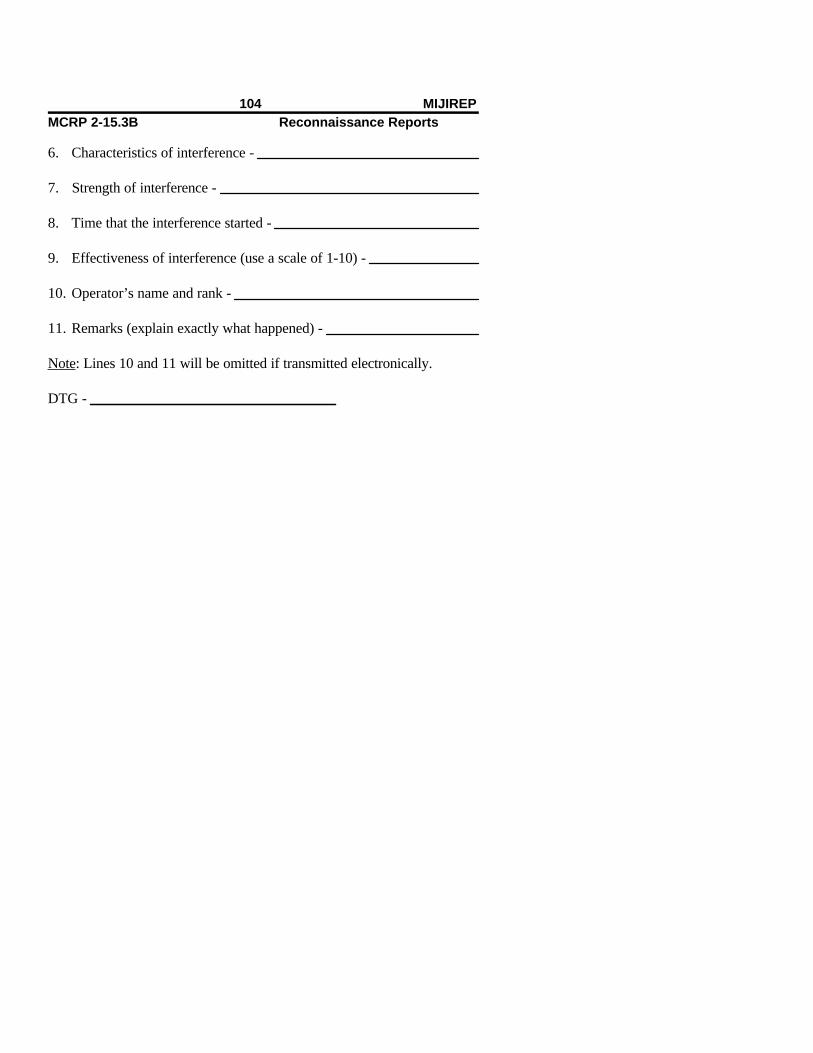
6. Characteristics of interference -
7. Strength of interference -
8. Time that the interference started -
9. Effectiveness of interference (use a scale of 1-10) -
10. Operator’s name and rank -
11. Remarks (explain exactly what happened) -
Note: Lines 10 and 11 will be omitted if transmitted electronically.
DTG -
104 MIJIREPMCRP 2-15.3B Reconnaissance Reports

Nuclear, Biological, and Chemical Report (NBCREP)
Begin the report with the subject line, including map sheet details asrequired.
ALPHA Units of Measurement. See the table on page 3.
BRAVO Location of Observer. This line describes the ob-server’s position by using a grid reference (encrypted) orsome other precoordinated method of position location.
CHARLIE Direction. This line indicates the direction of attackfrom the observer by using the unit of measurement des-ignated in line ALPHA.
DELTA Time Attack Started. This line reports the DTG thatthe attack started.
ECHO Time Attack Ended. This line reports the DTG that theattack ended.
FOXTROT Location of Area Being Attacked. This informationshould not be encrypted because the enemy alreadyknows the area that is being attacked.
GOLF Type of Attack. The type of delivery system being usedis stated: mortars, artillery, rockets, missiles, spray, or soon.
MCRP 2-15.3B Reconnaissance ReportsGuide
HOTEL Wind Direction and Velocity. The direction from whichthe wind is blowing is reported by using the unit of meas-urement designated in line ALPHA.
JULIET Type of Agent. If it can be determined, the type of agentis reported; if not, the observed effects are reported.
KILO Remarks. This line includes remarks as stated in the pa-trol’s IRs.
106 NBCREP

NBCREP Worksheet
_______________ this is _______________ (receiver) (sender)
NBCREP - (serial number followed by code name and map sheet details as required)
ALPHA -
BRAVO -
CHARLIE -
DELTA -
ECHO -
FOXTROT -
GOLF -
HOTEL -
JULIET -
KILO (remarks)-
DTG -
MCRP 2-15.3B Reconnaissance ReportsGuide

Railroad Reconnaissance Report (RAILREP)
Begin the report with the subject line, the serial number followed by rail-road designation (determined before the team is inserted), and map sheetdetails as required.
ALPHA Units of Measurement. See the table on page 3.
BRAVO DTG. This line reports the DTG of when the reconnais-sance was completed.
CHARLIE Location and Direction. This line provides the locationof the beginning and end of that part of the railroad that isactually reconnoitered. The cardinal direction of the axisis indicated with letters, for example, N (north), E (east),SW (southwest), and so on.
DELTA Military Classification. This assessment will only bemade by qualified personnel.
ECHO Length of Rails and Number of Ties. This informationis passed in two sections. The first section passes thelength of an individual section of rail, and the second sec-tion passes the number of ties per rail section. The lengthis reported using the unit of measurement reported in lineALPHA. Line ECHO information is transmitted in thefollowing manner:
E1.10
E2.8
MCRP 2-15.3B Reconnaissance ReportsGuide
In this example, ten represents the ten-meter length ofeach rail section, and eight represents the number of tiesper rail section.
FOXTROT Track Gauge. This is reported as directed in the team’sOPORD IRs, which must be fully understood beforeinsertion.
GOLF Track Width. This is reported in the following sequence:
1st. Outside width of track.
2nd. Inside width of track.
3rd. Width of railroad bed.
HOTEL Composition of Railroad Bed. A soil sample should bebrought back to be examined as part of the patrol report.Bed composition is reported by using the following nu-merical codes:
Railroad Bed Composition Number Code
Rock 1Gravel 2Cinders 3Timber 4Concrete 5Other (specify and briefly describe) 6
110 RAILREPMCRP 2-15.3B Reconnaissance Reports
JULIET Gradient. This is reported as a ratio. Critical gradientsshould be given in the team’s OPORD IRs.
KILO Railroad Conditions. If any portion of the track is dam-aged, the damage can be reported by using the followingnumerical code:
Track Condition Number Code
Undamaged 1
Boobytrapped But Not 2Damaged. The track is undamaged, but engineers will be required toclear all boobytraps to make thetrack safe so that it may be used byfriendly units.
Slightly Damaged. The track is damaged 3but probably capable of safely allowingtrains to pass at a reduced rate ofspeed and limited load capacity.Engineering work is required to allow the trains to travel at a sustained and safe rate.
Significantly Damaged. The track is not 4safe for passage of troops or cargo. Tracks will require a major engineeringeffort to make them safe for traffic but will not require starting a new track at anew location.
MCRP 2-15.3B Reconnaissance ReportsGuide

Destroyed 5
Concealment. The availability of concealment from theair should be reported by using the following code:
Concealment Along Tracks Number Code
Good concealment is available at 1regular intervals along the route.
Some concealment is available. 2
Little or no concealment is available. 3
MIKE Track Constrictions. Railroad constrictions will be re-ported in the following sequence:
1st. Nature of constriction.
2nd. Location of constriction.
3rd. Type of constriction, using the following lettercode and units of measurement designated in lineALPHA:
Type of Constriction Letter Code
Height AWidth BRadius of a curve CGradient D
112 RAILREPMCRP 2-15.3B Reconnaissance Reports
Other (specify and describe) E
NOVEMBER Location of Switching Stations. This line provides gridlocations of all switching stations along the section of therail line that has been reconnoitered.
PAPA Activity. All rail traffic along the route is reported, withemphasis on military traffic. Each sighting is numberedsequentially and includes the following information re-ported in the following sequence:
1. DTG of sighting.
2. Speed of the enemy train, reported by using the unitof measurement designated in line ALPHA followed bythe cardinal direction: N (north), SW (southwest), NE(northeast), and so on.
3. Location of the sighting, reported by grid reference.
4. Composition of the train in the following sequence: thenumber of each type of railroad car followed by the lettercode that designates that type of car.
Train Composition Letter Code
Engines APersonnel BFreight CFlat car DFuel car E
MCRP 2-15.3B Reconnaissance ReportsGuide
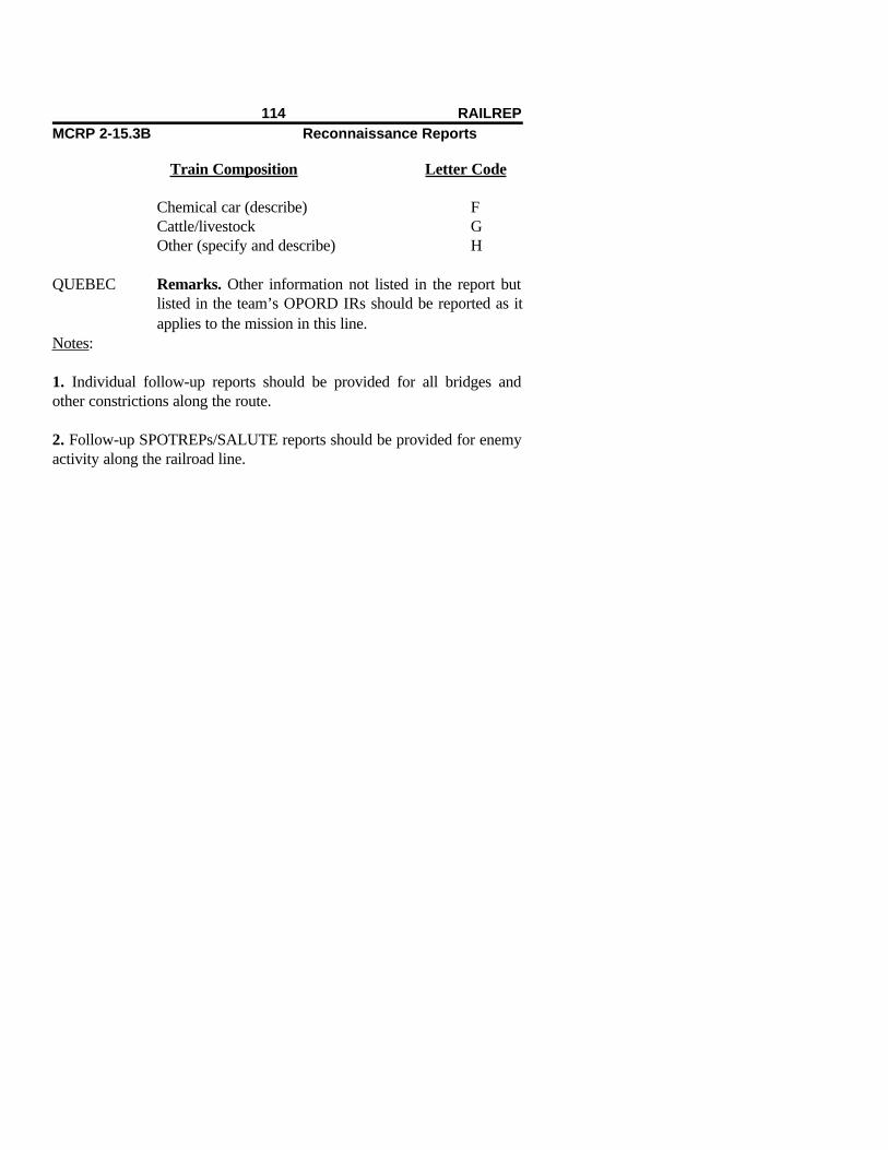
Train Composition Letter Code
Chemical car (describe) FCattle/livestock GOther (specify and describe) H
QUEBEC Remarks. Other information not listed in the report butlisted in the team’s OPORD IRs should be reported as itapplies to the mission in this line.
Notes:
1. Individual follow-up reports should be provided for all bridges andother constrictions along the route.
2. Follow-up SPOTREPs/SALUTE reports should be provided for enemyactivity along the railroad line.
114 RAILREPMCRP 2-15.3B Reconnaissance Reports
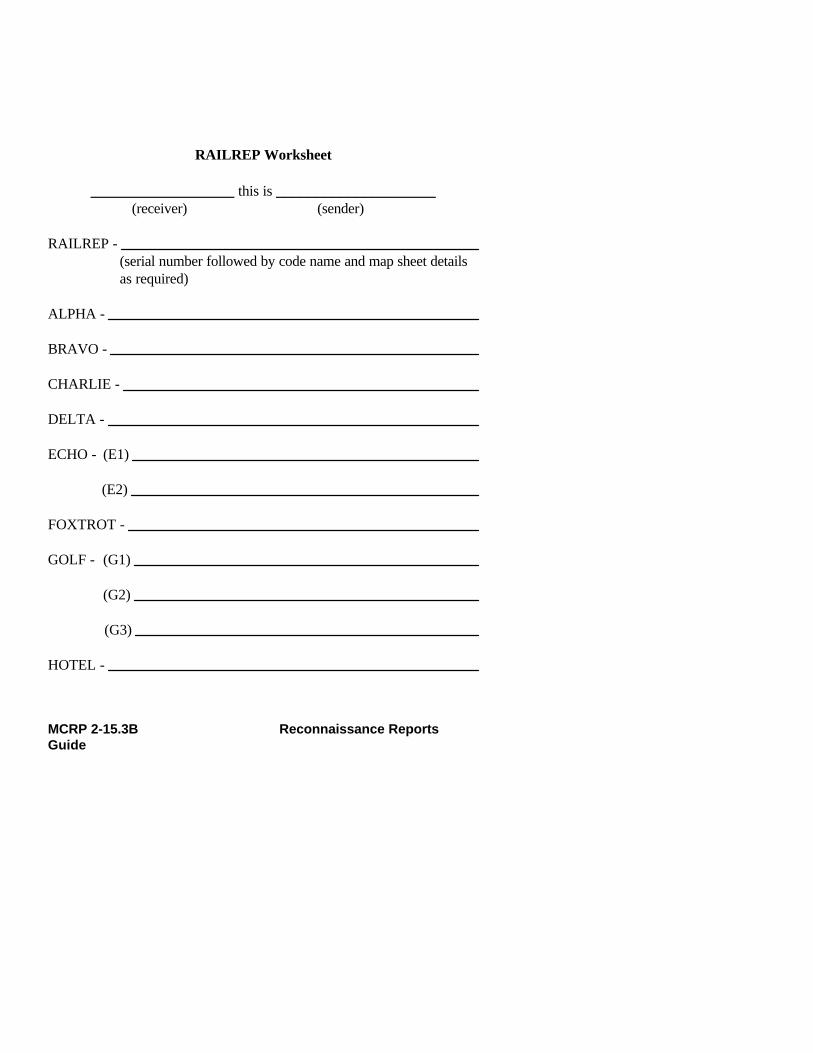
RAILREP Worksheet
__________________ this is ____________________(receiver) (sender)
RAILREP - (serial number followed by code name and map sheet details as required)
ALPHA -
BRAVO -
CHARLIE -
DELTA -
ECHO - (E1)
(E2)
FOXTROT -
GOLF - (G1)
(G2)
(G3)
HOTEL -
MCRP 2-15.3B Reconnaissance ReportsGuide
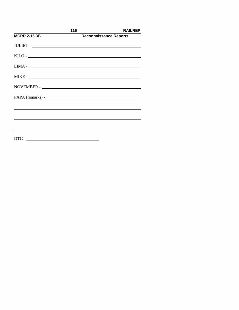
JULIET -
KILO -
LIMA -
MIKE -
NOVEMBER -
PAPA (remarks) -
DTG -
116 RAILREPMCRP 2-15.3B Reconnaissance Reports

Route and Road Report (ROUTEREP)
Begin the report with the subject line of the message followed by the serialnumber and map sheet details as required.
ALPHA Units of Measurement. See the table on page 3.
BRAVO Location. This line provides a grid reference of the startand finish of that part of the route that is actuallyreconnoitered.
CHARLIE Type of Route. The type of route is indicated by the fol-lowing letter code:
Type of Route Letter Code
All-weather route XLimited all-weather route YFair-weather route Z
Notes:
1. Route type X has the following characteristics:
A. The route is passable to all traffic in anyweather, except in deep snow or during flooding.
B. The route normally includes roads with water-proof surfaces only.
MCRP 2-15.3B Reconnaissance ReportsGuide

2. Route type Y has the following characteristics:
A. Volume of traffic may be limited by bad weather,for example, muddy verges or shoulders.
B. The route normally includes roads that do nothave waterproof surfaces and are considerably af-fected by rain, frost, thaw, or heat.
C. Roads may have to be closed for short periods.Heavy unrestricted use during adverse weather maycause a complete breakdown of the route surface.
3. Route type Z has the following characteristics:
A. Passage is possible only during fair weather.
B. The route quickly becomes impassable in badweather.
C. The route cannot be kept open by maintenanceshort of major construction.
DELTA Military Classification. This assessment will be madeonly by qualified personnel, for example, construction/combat engineers:
Class 50. Average traffic routes.
Class 80. Heavy traffic routes.
Class 100. Very heavy traffic routes.
118 ROUTEREP

ECHO Width. The width of the route is reported in two parts.The first is the average width of the traveled way. Thesecond is the average width of the entire route, includinggrading of the shoulder of the route. These measurementsare reported by using the units of measurement desig-nated in line ALPHA. The traveled way is the hard sur-face of the road/route; the width of grading is the width ofthe traveled way plus the width of the hard shoulders ofthe route.
FOXTROT Route Constrictions. These are listed individually anddescribed in the following sequence:
1st. Nature of constriction. This information is re-ported by using the following numerical code:
Type of Route Constriction Number Code
Height constriction 1Width constriction 2Radius-of-a-curve constriction 3Gradient constriction 4Other 5
2nd. Location of the constriction.
3rd. Dimension of the constriction, using the unit ofmeasurement designated in line ALPHA.
4th. Bypass potential of the constriction, using thefollowing letter code:
MCRP 2-15.3B Reconnaissance ReportsGuide

Bypass Potential Letter Code
Bypass easy—local detour Ppossible without engineeringeffort.
Bypass difficult—bypass possible Qonly after engineeringimprovements.
Bypass impossible. R
Note: The critical heights, widths, radius of a curve, andgradients will be reported by using the criteria set forth inthe IRs of the reconnaissance plan.
GOLF Concealment. The availability of concealment from theair will be categorized by using the following numericalcode:
Type of Concealment Number Code
Good Concealment. Available 1 at regular intervals along the reconnoitered section of the route.
Some Concealment. Available 2along the reconnoitered part of the route.
Little or No Concealment. Little 3to no concealment available along
120 ROUTEREP

the route actually reconnoitered.
HOTEL Special Considerations. This line of the report includesany other factors that may have to be considered by anylanding force that intends to use the reconnoitered route.The main meteorological obstacles are snow, flooding,and ice. Other considerations could include such prob-lems as refugees and local traffic. Hazards are listed byusing the following numerical codes:
Type of Hazard Number Code
Snow (refer to notes below) 1Flooding (refer to notes below) 2Ice (refer to notes below) 3Other (describe) 4
Note: The following letter codes are used as suffixes toclarify the seriousness of the snow, flooding, or ice condi-tion being reported.
Snow Conditions Letter Code
There is no hindrance to wheeled Pvehicles.
Movement is difficult for 4- Qwheel-drive vehicles. Somedigging or other routepreparation may be necessaryin places.
MCRP 2-15.3B Reconnaissance ReportsGuide
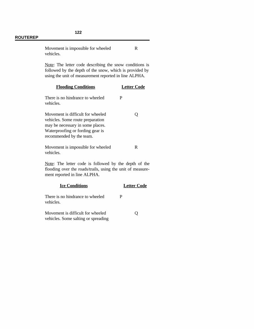
Movement is impossible for wheeled Rvehicles.
Note: The letter code describing the snow conditions isfollowed by the depth of the snow, which is provided byusing the unit of measurement reported in line ALPHA.
Flooding Conditions Letter Code
There is no hindrance to wheeled Pvehicles.
Movement is difficult for wheeled Qvehicles. Some route preparationmay be necessary in some places.Waterproofing or fording gear isrecommended by the team.
Movement is impossible for wheeled Rvehicles.
Note: The letter code is followed by the depth of theflooding over the roads/trails, using the unit of measure-ment reported in line ALPHA.
Ice Conditions Letter Code
There is no hindrance to wheeled Pvehicles.
Movement is difficult for wheeled Qvehicles. Some salting or spreading
122 ROUTEREP

of gravel/sand in places is required to make the route passable.
Movement is impossible for wheeled Rvehicles without route preparationbefore vehicle use of the route.
The condition is temporary; ice should Smelt off. The letter code is followedby the DTG of when the team expects the ice to melt.
Note: The letter code describing the ice condition shouldbe followed by the depth of the ice on the route. If thecondition is temporary and the time/DTG when the icecondition should clear can be estimated, then this estimateis sent.
JULIET Remarks. Any additional information that may be helpfulto operational planning and possible unit deployment, forexample, drifting conditions of snow, speed of water dur-ing flooding conditions, wind speed and wind chill infor-mation, and so on, is provided.
MCRP 2-15.3B Reconnaissance ReportsGuide

ROUTEREP Worksheet
_______________ this is ______________ (receiver) (sender)
ROUTEREP - (serial number followed by code name and map sheet details as required)
ALPHA -
BRAVO -
CHARLIE -
DELTA -
ECHO -
FOXTROT -
GOLF -
HOTEL -
JULIET (remarks) -
DTG -
124 ROUTEREP

Standard Shelling Report (SHELREP), Mortaring Report(MORTREP), or Bombing Report (BOMREP) (State Which)
ALPHA Units of Measurement. See the table on page 3.
BRAVO Unit of Origin. This line reports the current call sign, ad-dress, and group or code name.
CHARLIE Position of Observer. A grid reference is preferred. Thisshould be encoded if the station is operating on an uncov-ered net.
DELTA Bearing of Flash or Sound. A bearing or azimuth (asdesignated in line ALPHA) of flash, sound of impact,groove of impact, or original flight of missiles or rocketsis provided. This line is omitted for aircraft bombing.
ECHO Time From. The time shelling/bombing began.
FOXTROT Time To. The time shelling/bombing ended.
GOLF Area Shelled, Mortared, or Bombed. This may betransmitted either as:
1. Polar Plot. This includes the bearing/azimuth anddistance/range of impact from the observer. (This infor-mation should be encoded to prevent the observer frombeing bracketed as a result of the enemy getting a backazimuth and range to the observer. This is not the pre-ferred technique to locate the impact of the round.)
MCRP 2-15.3B Reconnaissance ReportsGuide

2. Grid Reference. This information should not be en-coded because the enemy already knows where he isshooting and this information will only assist the enemyin breaking the encryption. (This is the preferred tech-nique for transmitting this information.)
HOTEL Nature of Fire. The purpose for which the fire is beingused is reported: registration, bombardment, harassment,or so on (may be omitted for aircraft).
JULIET Caliber/Size of Ordnance Being Fired. The size of theweapon being fired or the size of the bomb being droppedis reported (if a determination can be made).
KILO Time From Flash to Bang. The time from observing theflash to hearing the sound of the explosion of the impactis reported (recorded in seconds).
LIMA Battle Damage Assessment
MIKE Remarks
126 SHELREP/MORTREP/BOMREPMCRP 2-15.3B Reconnaissance Reports

SHELREP Worksheet
_____________ this is _____________(receiver) (sender)
_______________ REP _______________(serial number and type of report (shell, mortar, bomb) followed by codename and map sheet details as required)
ALPHA -
BRAVO -
CHARLIE -
DELTA -
ECHO -
FOXTROT -
GOLF -
HOTEL -
JULIET -
KILO -
LIMA -
MCRP 2-15.3B Reconnaissance ReportsGuide

MIKE (remarks) -
DTG -
128 SHELREP/MORTREP/BOMREPMCRP 2-15.3B Reconnaissance Reports

Situation Report (SITREP) and Worksheet
_____________ this is ______________ (receiver) (sender)
SITREP - (serial number followed by code name and map sheet details as required)
1. DTG -
2. Friendly position (encrypted) -
3. Activities conducted (since last report) -
4. Actions planned (next 12-hour period) -
5. Logistical requirements (food, ammunition, pyrotechnics, water, andso on) -
MCRP 2-15.3B Reconnaissance ReportsGuide

6. Personnel casualties (since last CASREP) -
7. Remarks -
DTG -
130 SITREPMCRP 2-15.3B Reconnaissance Reports
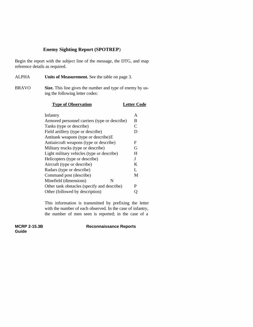
Enemy Sighting Report (SPOTREP)
Begin the report with the subject line of the message, the DTG, and mapreference details as required.
ALPHA Units of Measurement. See the table on page 3.
BRAVO Size. This line gives the number and type of enemy by us-ing the following letter codes:
Type of Observation Letter Code
Infantry AArmored personnel carriers (type or describe) BTanks (type or describe) CField artillery (type or describe) DAntitank weapons (type or describe)EAntiaircraft weapons (type or describe) FMilitary trucks (type or describe) GLight military vehicles (type or describe) HHelicopters (type or describe) JAircraft (type or describe) KRadars (type or describe) LCommand post (describe) MMinefield (dimensions) NOther tank obstacles (specify and describe) POther (followed by description) Q
This information is transmitted by prefixing the letterwith the number of each observed. In the case of infantry,the number of men seen is reported; in the case of a
MCRP 2-15.3B Reconnaissance ReportsGuide

minefield, the number of minefields is reported. The di-mensions of the minefields are reported by using the unitof measurement from line ALPHA for each mine- field.
CHARLIE Activity. This line describes the activity of the enemy byusing the following numerical code:
Type of Activity Number Code
On the move (followed by 1direction and speed)
Stationary, but not dug in 2In prepared positions 3Other (describe) 4
DELTA Location. The position of the enemy is provided by usingthe grid reference or another agreed-on system of positionreference.
ECHO Unit. An identification of the enemy unit is provided if itcan be determined. If not, a description is given thatmight be helpful to the tasking agency. If a positive iden-tification is made, indication is required as to how thiswas achieved.
FOXTROT Time. The DTG of the sighting is reported.
GOLF Equipment. The identity or description of any weaponsor equipment observed is provided.
132 SPOTREPMCRP 2-15.3B Reconnaissance Reports

HOTEL Remarks. Any additional details are included that mighthelp to clarify enemy activities, strengths, or intentionsfor an intelligence assessment.
MCRP 2-15.3B Reconnaissance ReportsGuide

SPOTREP Worksheet
_____________ this is ______________ (receiver) (sender)
SPOTREP - (serial number followed by code name and map sheet details as required)
ALPHA -
BRAVO -
CHARLIE -
DELTA -
ECHO -
FOXTROT -
GOLF -
HOTEL (remarks) -
DTG -
134 SPOTREPMCRP 2-15.3B Reconnaissance Reports Guide

Surf Obsevation Report (SURFREP)
Begin the report with the subject line of the message and the serial num-ber, followed by the code name and/or map sheet information as required.
ALPHA Units of Measurement. See the table on page 3.
BRAVO Time. This line provides the DTG of when the SUR-FREP was completed.
CHARLIE Significant Breaker Height. This includes the averageheight (in the unit of measurement designated in line AL-PHA) of the highest one-third of all breakers observed ina 10-minute period (expressed to the nearest one-half footor one-tenth meter).
DELTA Maximum Breaker Height. The largest breaker ob-served is reported in the unit of measurement designatedin line ALPHA.
ECHO Period. This line provides the time (in seconds) betweenbreakers to the nearest one-half second.
FOXTROT Breaker Types. The number of each type of wave is pro-vided, followed by the letter code of that type of wave, asindicated by using the following letter code:
Type of Wave Letter Code
MCRP 2-15.3B Reconnaissance Reports Guide135
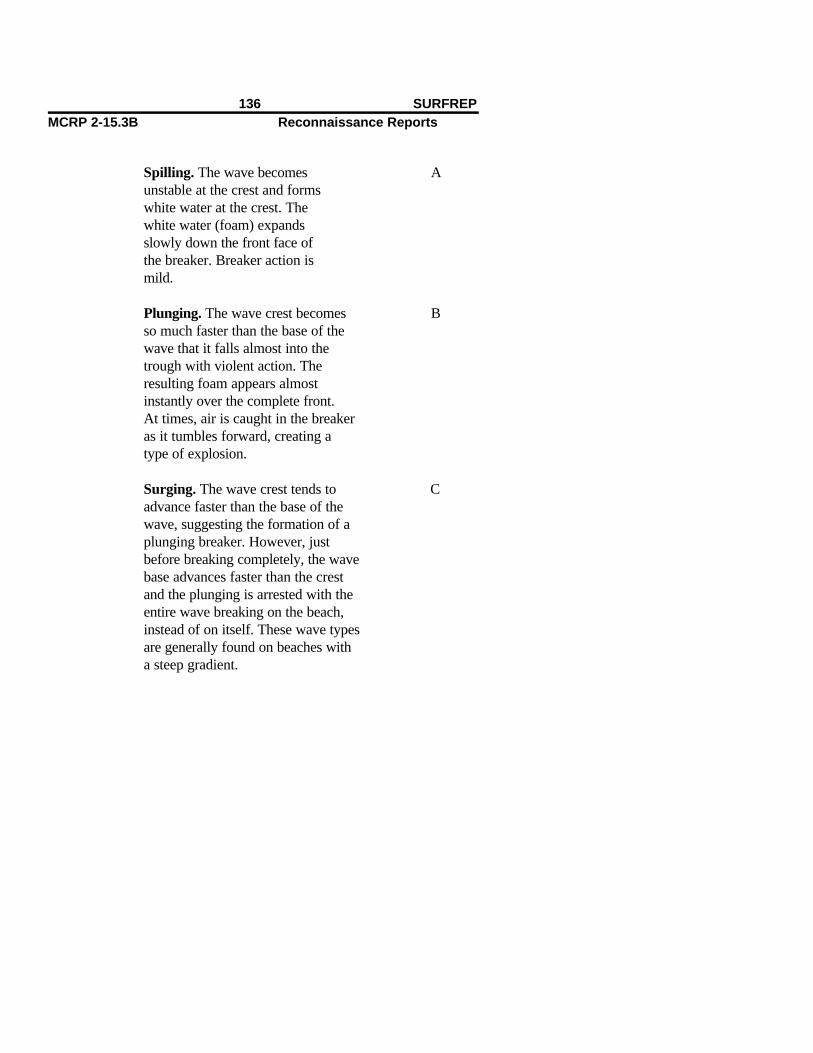
Spilling. The wave becomes Aunstable at the crest and formswhite water at the crest. Thewhite water (foam) expandsslowly down the front face ofthe breaker. Breaker action ismild.
Plunging. The wave crest becomes Bso much faster than the base of thewave that it falls almost into thetrough with violent action. The resulting foam appears almostinstantly over the complete front.At times, air is caught in the breakeras it tumbles forward, creating atype of explosion.
Surging. The wave crest tends to Cadvance faster than the base of thewave, suggesting the formation of aplunging breaker. However, justbefore breaking completely, the wavebase advances faster than the crest and the plunging is arrested with theentire wave breaking on the beach,instead of on itself. These wave typesare generally found on beaches witha steep gradient.
136 SURFREPMCRP 2-15.3B Reconnaissance Reports
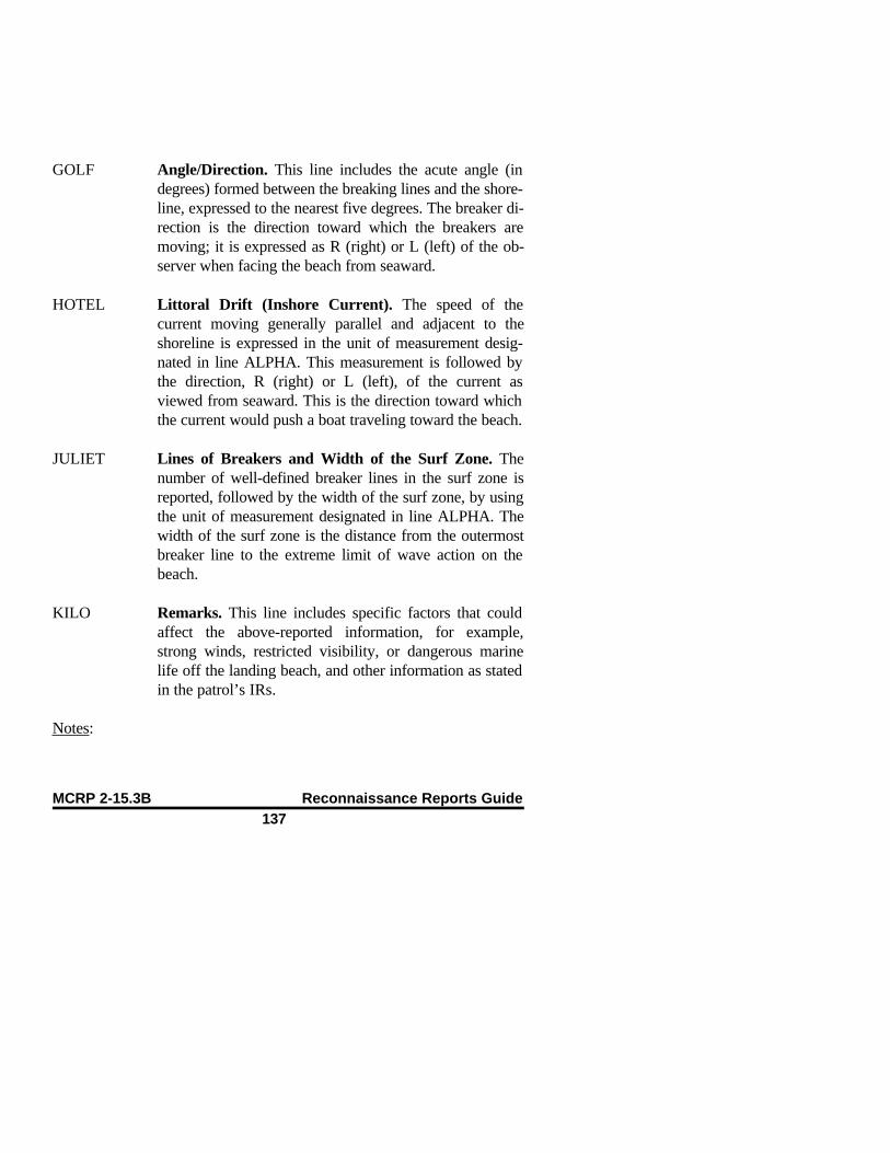
GOLF Angle/Direction. This line includes the acute angle (indegrees) formed between the breaking lines and the shore-line, expressed to the nearest five degrees. The breaker di-rection is the direction toward which the breakers aremoving; it is expressed as R (right) or L (left) of the ob-server when facing the beach from seaward.
HOTEL Littoral Drift (Inshore Current). The speed of thecurrent moving generally parallel and adjacent to theshoreline is expressed in the unit of measurement desig-nated in line ALPHA. This measurement is followed bythe direction, R (right) or L (left), of the current asviewed from seaward. This is the direction toward whichthe current would push a boat traveling toward the beach.
JULIET Lines of Breakers and Width of the Surf Zone. Thenumber of well-defined breaker lines in the surf zone isreported, followed by the width of the surf zone, by usingthe unit of measurement designated in line ALPHA. Thewidth of the surf zone is the distance from the outermostbreaker line to the extreme limit of wave action on thebeach.
KILO Remarks. This line includes specific factors that couldaffect the above-reported information, for example,strong winds, restricted visibility, or dangerous marinelife off the landing beach, and other information as statedin the patrol’s IRs.
Notes:
MCRP 2-15.3B Reconnaissance Reports Guide137

1. Spilling wave action can generally be considered the least violent anddangerous to small boats and landing craft.
2. Surging wave action is generally the most violent and dangerous tosmall boats and landing craft because of the breaking action directly ontothe beach.
3. Plunging wave action falls somewhere in between the two extremes, de-pending on storm action and other considerations.
138 SURFREPMCRP 2-15.3B Reconnaissance Reports

SURF OBERVATION WORKSHEET
Wave Height Observation ComputationsSpilling - A Plunging - B Wave Period ComputationSurging - C
Elapsed Time: Min. Sec.Time Begun _____ Total Seconds:
Total Seconds = (Breaker Period)ABC ABC ABC ABC ABC ABC No. of Waves (Line Echo)
Average Wave Height ComputationABC ABC ABC ABC ABC ABC
Height x Occurrence = Product
ABC ABC ABC ABC ABC ABC x =
x = ABC ABC ABC ABC ABC ABC
x =
ABC ABC ABC ABC ABC ABC x =
Total of Products = ABC ABC ABC ABC ABC ABC
Total of Products = Average Wave Heightof Highest 1/3 Breakers
ABC ABC ABC ABC ABC ABC (Line Charlie)
Percentage of Waves By Type:ABC ABC ABC ABC ABC ABC
No. of ANo. of B
ABC ABC ABC ABC ABC ABC No. of C (continued on next page)
MCRP 2-15.3B Reconnaissance Reports Guide139

No. of Type of Wave x 100 = % of WaveABC ABC ABC ABC ABC ABC Total No. of Waves Type
(Round tonearest 10)
ABC ABC ABC ABC ABC ABC
ABC ABC ABC ABC ABC ABC
ABC ABC ABC ABC ABC ABC
ABC ABC ABC ABC ABC ABC
ABC ABC ABC ABC ABC ABC
Time Ended
140 SURFREPMCRP 2-15.3B Reconnaissance Reports
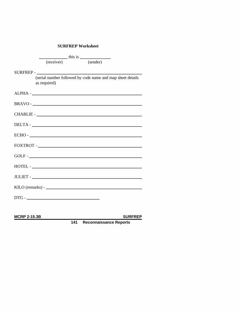
SURFREP Worksheet
____________ this is _____________(receiver) (sender)
SURFREP - (serial number followed by code name and map sheet details as required)
ALPHA -
BRAVO -
CHARLIE -
DELTA -
ECHO -
FOXTROT -
GOLF -
HOTEL -
JULIET -
KILO (remarks) -
DTG -
MCRP 2-15.3B SURFREP141 Reconnaissance Reports

Tunnel Report (TUNNELREP)
Begin the report with the subject line of the message followed by the re-port number/serial number, code name, and map sheet details as required.
ALPHA Units of Measurement. See the table on page 3.
BRAVO DTG. This line reports the time when reconnaissancewas completed.
CHARLIE Location and Classification. This line provides the gridreference of the tunnel location, followed by the engineer-ing classification, if known. If there is not a person in thepatrol who is qualified to classify the tunnel or if, becauseof the enemy situation, the patrol was unable to get thetunnel classification, then the letter code NIL will be re-ported in its place.
DELTA Length and Condition of Tunnel. This information isreported in the units of measurement designated in lineALPHA in the following sequence: the length of the tun-nel, followed by the condition of the tunnel. Tunnel dam-age will be classified by using the following letter code:
Condition of Tunnel Letter Code
Not Damaged. There are no restrictions Ato military traffic other than the dimensionsof the tunnel.
Boobytrapped, But Not Damaged. B
MCRP 2-15.3B Reconnaissance ReportsGuide
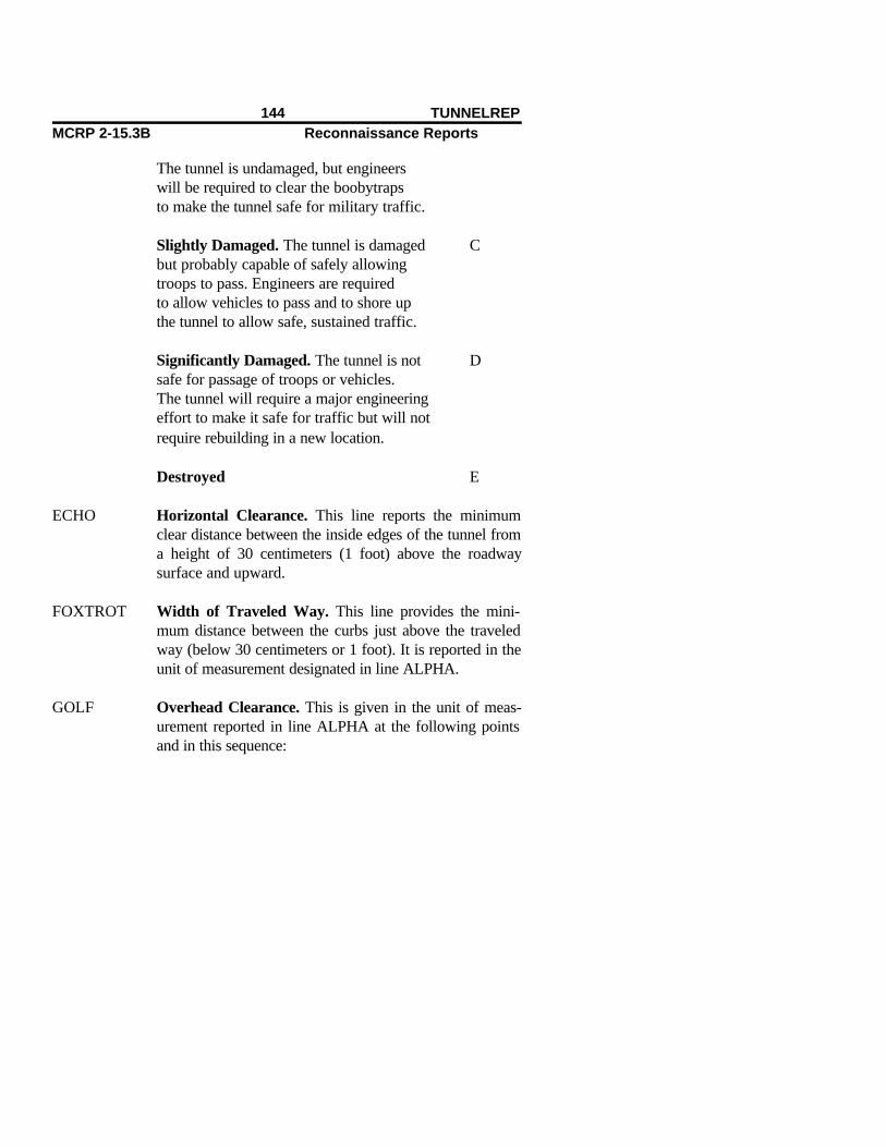
The tunnel is undamaged, but engineerswill be required to clear the boobytrapsto make the tunnel safe for military traffic.
Slightly Damaged. The tunnel is damaged Cbut probably capable of safely allowingtroops to pass. Engineers are requiredto allow vehicles to pass and to shore upthe tunnel to allow safe, sustained traffic.
Significantly Damaged. The tunnel is not Dsafe for passage of troops or vehicles.The tunnel will require a major engineering effort to make it safe for traffic but will notrequire rebuilding in a new location.
Destroyed E
ECHO Horizontal Clearance. This line reports the minimumclear distance between the inside edges of the tunnel froma height of 30 centimeters (1 foot) above the roadwaysurface and upward.
FOXTROT Width of Traveled Way. This line provides the mini-mum distance between the curbs just above the traveledway (below 30 centimeters or 1 foot). It is reported in theunit of measurement designated in line ALPHA.
GOLF Overhead Clearance. This is given in the unit of meas-urement reported in line ALPHA at the following pointsand in this sequence:
144 TUNNELREPMCRP 2-15.3B Reconnaissance Reports

1st. Left shoulder.
2nd. Center of roadway.
3rd. Right shoulder.
Note: If all overhead clearances are the same, report themeasurement just once; it is understood that the over-head clearances are all the same.
HOTEL Gradient. The gradient should be reported as a ratio.
INDIA Tunnel Use. The intended use of the tunnel will be re-ported by using the following numerical code:
Type of Tunnel Number Code
Highway/road tunnel 1Railroad tunnel 2Other (specify and describe briefly) 3
JULIET Tunnel Bypass. This information is reported in the fol-lowing sequence:
1st. Location of bypass.
2nd. Overall bypass potential, using the followingletter code:
Bypass Potential Letter Code
MCRP 2-15.3B Reconnaissance ReportsGuide
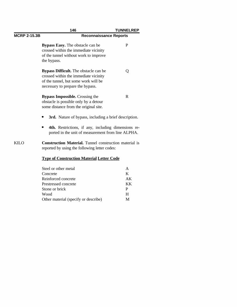
Bypass Easy. The obstacle can be Pcrossed within the immediate vicinityof the tunnel without work to improvethe bypass.
Bypass Difficult. The obstacle can be Q crossed within the immediate vicinity of the tunnel, but some work will be necessary to prepare the bypass.
Bypass Impossible. Crossing the Robstacle is possible only by a detoursome distance from the original site.
3rd. Nature of bypass, including a brief description.
4th. Restrictions, if any, including dimensions re-ported in the unit of measurement from line ALPHA.
KILO Construction Material. Tunnel construction material isreported by using the following letter codes:
Type of Construction Material Letter Code
Steel or other metal AConcrete KReinforced concrete AKPrestressed concrete KKStone or brick PWood HOther material (specify or describe) M
146 TUNNELREPMCRP 2-15.3B Reconnaissance Reports

LIMA Remarks. Any other important information is reported inthis line. Such information will be designated in theteam’s OPORD IRs.
MCRP 2-15.3B Reconnaissance ReportsGuide

TUNNELREP Worksheet
_______________ this is _______________ (receiver) (sender)
TUNNELREP - (serial number followed by code name and map sheet details as required)
ALPHA-
BRAVO -
CHARLIE -
DELTA -
ECHO -
FOXTROT -
GOLF -
HOTEL -
INDIA -
JULIET -
KILO -
148 TUNNELREPMCRP 2-15.3B Reconnaissance Reports
LIMA (remarks) -
DTG -
MCRP 2-15.3B Reconnaissance ReportsGuide

International Morse Code
MCRP 2-15.3B Reconnaissance Reports Guide151 International Morse

152 International Morse CodeMCRP 2-15.3B Reconnaissance Reports
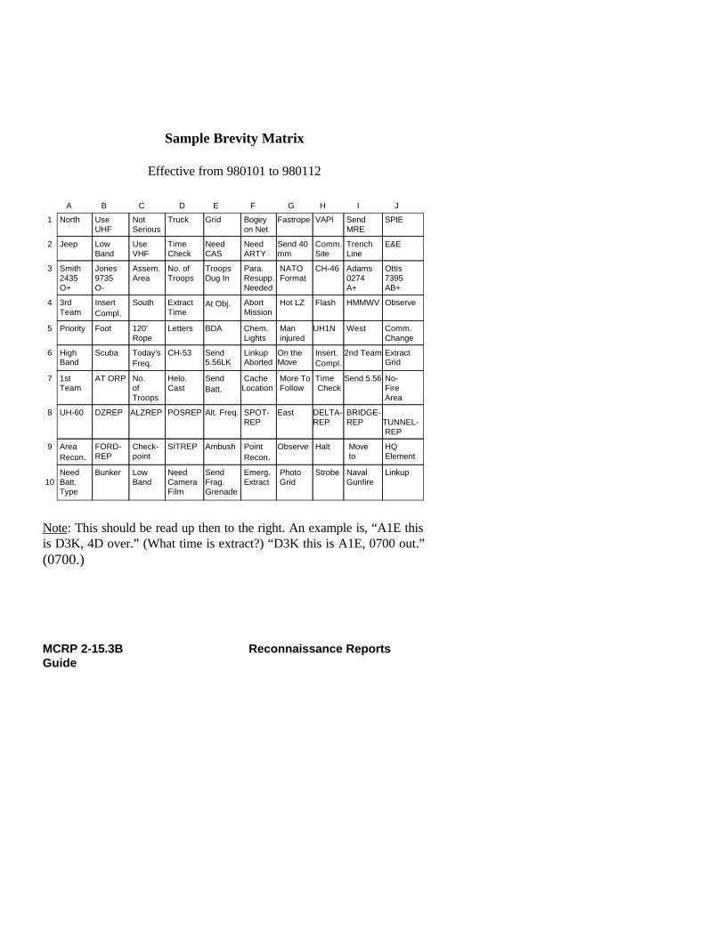
Sample Brevity Matrix
Effective from 980101 to 980112
A B C D E F G H I J
1 North UseUHF
Not Serious
Truck Grid Bogey on Net
Fastrope VAPI Send MRE
SPIE
2 Jeep LowBand
Use VHF
TimeCheck
NeedCAS
Need ARTY
Send 40mm
Comm. Site
Trench Line
E&E
3 Smith2435O+
Jones9735O-
Assem. Area
No. ofTroops
TroopsDug In
Para. Resupp. Needed
NATO Format
CH-46 Adams 0274 A+
Ottis 7395 AB+
4 3rdTeam
InsertCompl.
South ExtractTime
At Obj. Abort Mission
Hot LZ Flash HMMWV Observe
5 Priority Foot 120’ Rope
Letters BDA Chem. Lights
Man injured
UH1N West Comm. Change
6 HighBand
Scuba Today’s Freq.
CH-53 Send5.56LK
Linkup Aborted
On theMove
Insert. Compl.
2nd Team Extract Grid
7 1stTeam
AT ORP No. of Troops
Helo.Cast
SendBatt.
Cache Location
More To Follow
Time Check
Send 5.56 No- Fire Area
8 UH-60 DZREP ALZREP POSREP Alt. Freq. SPOT- REP
East DELTA-REP
BRIDGE- REP
TUNNEL- REP
9 AreaRecon.
FORD-REP
Check- point
SITREP Ambush Point Recon.
Observe Halt Move to
HQ Element
10
NeedBatt.Type
Bunker Low Band
NeedCameraFilm
SendFrag.Grenade
Emerg. Extract
Photo Grid
Strobe Naval Gunfire
Linkup
Note: This should be read up then to the right. An example is, “A1E thisis D3K, 4D over.” (What time is extract?) “D3K this is A1E, 0700 out.”(0700.)
MCRP 2-15.3B Reconnaissance ReportsGuide

Brevity Matrix Information
The following is a sampling of items of information or events that couldbe included in a brevity matrix. Use only those items that pertain to a par-ticular reconnaissance patrol to avoid filling the brevity matrix with infor-mation that is of no use.
Platoon 1st team 2nd team
3rd team Insertion complete Extraction complete
Mission Extraction time Extraction gridcompromised
Use VHF Use HF Use alternate frequency
Need emergency On the move More to followextraction
Numbers 0-9 North South
East West Abort mission
Mission complete All North Atlantic Cache locationTreaty Organization(NATO) formats
Conduct linkup Linkup aborted Flash
Priority Routine Need resupply
154 Sample Brevity MatrixMCRP 2-15.3B Reconnaissance Reports
At objective At objective Awaiting rally point (ORP)extraction
In harbor site In ambush site Have no secure
CH-46 CH-53 UH-60
Rappel Fastrope SPIE
High-mobility, Truck Jeepmultipurposewheeled vehicle(HMMWV)
E&E Restrictive fire area No-fire area
Conduct of fire net Troops in open Troops dug in
BDA Trench line Number of troops
120-foot rope Observer Parachute
Letters High band Low band
Moving to check- Need camera film Air panelspoint number
Chemiluminescent Scuba Helocastlights
MCRP 2-15.3B Reconnaissance ReportsGuide

Foot Need fuel Visual approach path indicator (VAPI)
Communications Assembly area Stand by to controlsite
Communications Zulu time Time checkchange
156 Sample Brevity MatrixMCRP 2-15.3B Reconnaissance Reports

Acronyms
ALZ . . . . . . . . . . . . . . . . . . . . . . . . . . . . . . . . . . . . . . . . . . . . . . . . aircraft landing zoneALZREP . . . . . . . . . . . . . . . . . . . . . . . . . . . . . . . . . . . . aircraft landing zone reportAMSL . . . . . . . . . . . . . . . . . . . . . . . . . . . . . . . . . . . . . . . . . . . . . above mean sea levelART . . . . . . . . . . . . . . . . . . . . . . . . . . . . . . . . . . . amphibious reconnaissance team
BEACHREP . . . . . . . . . . . . . . . . . . . . . . . . . . . . . . . . . . . . . . . . beach survey reportBOB . . . . . . . . . . . . . . . . . . . . . . . . . . . . . . . . . . . . . . . . . . . . . . . . . . . . . . back of beachBOMREP . . . . . . . . . . . . . . . . . . . . . . . . . . . . . . . . . . . . . . . . . . . . . . . bombing reportBRIDGEREP . . . . . . . . . . . . . . . . . . . . . . . . . . . . . . . . . . . . . . . . . . . . . . bridge report
CASREP . . . . . . . . . . . . . . . . . . . . . . . . . . . . . . . . . . . . . . . . . . . . . . . . . casualty reportCATF . . . . . . . . . . . . . . . . . . . . . . . . . . . . . . . commander, amphibious task forceCEOI . . . . . . . . . . . . . . . . . . comminications-electronics operating instructionsCLF . . . . . . . . . . . . . . . . . . . . . . . . . . . . . . . . . . . . . . . . . . . commander, landing forceCONBEREP . . . . . . . . . . . . . . . . . . confirmatory beach reconnaissance reportCONTACREP . . . . . . . . . . . . . . . . . . . . . . . . . . . . . . . . . . . . . . . . . . . . contact reportCW . . . . . . . . . . . . . . . . . . . . . . . . . . . . . . . . . . . . . . . . . . . . . . . . . . . . continuous wave
DACT . . . . . . . . . . . . . . . . . . . . . . . digital automated communications terminalDELTAREP . . . . . . . . . . . . . . . . . . . . . . . . . . . . . . . . . . . . . . . . river/estuary reportDP . . . . . . . . . . . . . . . . . . . . . . . . . . . . . . . . . . . . . . . . . . . . . . . . . . . . . . . . . . datum pointDTG . . . . . . . . . . . . . . . . . . . . . . . . . . . . . . . . . . . . . . . . . . . . . . . . . . . . date-time groupDZREP . . . . . . . . . . . . . . . . . . . . . . . . . . . . . . . . . . . . . . . . . . . . . . . . drop zone report
E&E . . . . . . . . . . . . . . . . . . . . . . . . . . . . . . . . . . . . . . . . . . . . . . . . . evasion and escapeEEI . . . . . . . . . . . . . . . . . . . . . . . . . . . . . . . . . . . . . . essential element of information
MCRP 2-15.3B Reconnaissance ReportsGuide

FIRREP . . . . . . . . . . . . . . . . . . . . . . . . . . . . . . . . . . . . frequency interference reportFLASHREP . . . . . . . . . . . . . . . . . . . . . . . . . . . . . . . . . . . . . . . . . . flash/action reportFMFM . . . . . . . . . . . . . . . . . . . . . . . . . . . . . . . . . . . . . . Fleet Marine Force manualFMFRP . . . . . . . . . . . . . . . . . . . . . . . . Fleet Marine Force reference publicationFORDREP . . . . . . . . . . . . . . . . . . . . . . . . . . . . . . . . . . . . . . . . . . . . . river ford report
HC . . . . . . . . . . . . . . . . . . . . . . . . . . . . . . . . . . . . . . . . . . . . . . . . . . . . . . . . . white smokeHELLSREP . . . . . . . . . . . . . . . . . . . . . . . . . . . . . . . . helicopter landing site reportHF . . . . . . . . . . . . . . . . . . . . . . . . . . . . . . . . . . . . . . . . . . . . . . . . . . . . . . . high frequencyHMMWV . . . . . . . . . . . . . . . . . . high-mobility, multipurpose wheeled vehicle
IP . . . . . . . . . . . . . . . . . . . . . . . . . . . . . . . . . . . . . . . . . . . . . . . . . . . . . . . . . . impact pointIR . . . . . . . . . . . . . . . . . . . . . . . . . . . . . . . . . . . . . . . . . . . . . . information requirement
KIA . . . . . . . . . . . . . . . . . . . . . . . . . . . . . . . . . . . . . . . . . . . . . . . . . . . . . . killed in action
MCRP . . . . . . . . . . . . . . . . . . . . . . . . . . . . . . Marine Corps reference publicationMHW . . . . . . . . . . . . . . . . . . . . . . . . . . . . . . . . . . . . . . . . . . . . . . . . . mean high waterMIA . . . . . . . . . . . . . . . . . . . . . . . . . . . . . . . . . . . . . . . . . . . . . . . . . . . . missing in actionMIJI . . . . . . . . . . . . . . . . . . . . meaconing, intrusion, jamming, and interferenceMIJIREP . . . . . . . . meaconing, intrusion, jamming, and interference reportMLW . . . . . . . . . . . . . . . . . . . . . . . . . . . . . . . . . . . . . . . . . . . . . . . . . . . mean low waterMORTREP . . . . . . . . . . . . . . . . . . . . . . . . . . . . . . . . . . . . . . . . . . . . mortaring report
NAR . . . . . . . . . . . . . . . . . . . . . . . . . . . . . . . . . . . . . . . . . . . . . . . . . . not able to recordNATO . . . . . . . . . . . . . . . . . . . . . . . . . . . . . . North Atlantic Treaty OrganizationNBC . . . . . . . . . . . . . . . . . . . . . . . . . . . . . . . . . . . nuclear, biological, and chemicalNBCREP . . . . . . . . . . . . . . . . . . . . . . . . nuclear, biological, and chemical reportNC . . . . . . . . . . . . . . . . . . . . . . . . . . . . . . . . . . . . . . . . . . . . . . . . . . . . . . . . . . . . no change
OIR . . . . . . . . . . . . . . . . . . . . . . . . . . . . . . . . . . . . . . . other information requirementOPORD . . . . . . . . . . . . . . . . . . . . . . . . . . . . . . . . . . . . . . . . . . . . . . . . . operation order
158 AcronymsMCRP 2-15.3B Reconnaissance Reports

ORP . . . . . . . . . . . . . . . . . . . . . . . . . . . . . . . . . . . . . . . . . . . . . . . . objective rally point
POW . . . . . . . . . . . . . . . . . . . . . . . . . . . . . . . . . . . . . . . . . . . . . . . . . . . . prisoner of warRAILREP . . . . . . . . . . . . . . . . . . . . . . . . . . . . . . . . railroad reconnaissance reportROUTEREP . . . . . . . . . . . . . . . . . . . . . . . . . . . . . . . . . . . . . . route and road report
SALUTE . . . . . . . . . . . . . . . . . . . size, activity, location, unit, time, equipmentSHELREP . . . . . . . . . . . . . . . . . . . . . . . . . . . . . . . . . . . . . . . . . . . . . . . shelling reportSITREP . . . . . . . . . . . . . . . . . . . . . . . . . . . . . . . . . . . . . . . . . . . . . . . . . situation reportSPIE . . . . . . . . . . . . . . . . . . . . . . . . . . . . . . special patrol insertion and extractionSPOTREP . . . . . . . . . . . . . . . . . . . . . . . . . . . . . . . . . . . . . . . . enemy sighting reportSTANAG . . . . . . . . . . . . . . . . . . . . . . . . . . . . . . . . . . . . standardization agreementSURFREP . . . . . . . . . . . . . . . . . . . . . . . . . . . . . . . . . . . . . . . surf observation report
TAP . . . . . . . . . . . . . . . . . . . . . . . . . . . . . . . . . . . . . . . . . . . . . . . target approach pointTUNNELREP . . . . . . . . . . . . . . . . . . . . . . . . . . . . . . . . . . . . . . . . . . . . . . tunnel report
UHF . . . . . . . . . . . . . . . . . . . . . . . . . . . . . . . . . . . . . . . . . . . . . . . . ultrahigh frequencyULLA . . . . . . . . . . . . . . . . . . . . . . . . . . . . . . . . . . . . . . . . . . ultra-low-level approach
VAPI . . . . . . . . . . . . . . . . . . . . . . . . . . . . . . . . . . . . . visual approach path indicatorVHF . . . . . . . . . . . . . . . . . . . . . . . . . . . . . . . . . . . . . . . . . . . . . . . . very high frequency
WIA . . . . . . . . . . . . . . . . . . . . . . . . . . . . . . . . . . . . . . . . . . . . . . . . . wounded in actionWLTS . . . . . . . . . . . . . . . . . . . . . . . . . . . . . . . . . waterline at the time of soundingWP . . . . . . . . . . . . . . . . . . . . . . . . . . . . . . . . . . . . . . . . . . . . . . . . . . . . white phosphorus
MCRP 2-15.3B Reconnaissance ReportsGuide

References
Fleet Marine Force Manual (FMFM) 3-30, Communications
Fleet Marine Force Reference Publication (FMFRP) 3-34, Field AntennaHandbook (under revision as MCRP 6-22D)
Standardization Agreement (STANAG) 3570, Drop Zones and Extrac-tion Zones—Criteria and Marking
MCRP 2-15.3B Reconnaissance ReportsGuide