mct1605-r7
DESCRIPTION
1TRANSCRIPT

1
Megger
User’s Guide For
MCT1605 Catalog No. 80513
Megger Multi-Tap Automatic Current Transformer Test Set
Megger 4271 Bronze Way
Dallas Tx-75237-1017, USA.
T+1 (800) 723 2861 (USA only) T+1 (214) 330 3203 (International) F +1 (214) 337 3038
P/N 80513 Rev7.0 Date 8-12-10
2
Table of Contents List of Figures ..................................................................................................................... 3 Safety Precautions............................................................................................................... 4 Input Power precautions ..................................................................................................... 5 Warning and Caution Notices............................................................................................. 5 Introduction......................................................................................................................... 6 Preparation for use .............................................................................................................. 8 Basic Theory ....................................................................................................................... 9
General........................................................................................................................... 9 Ratio Test ....................................................................................................................... 9 Polarity Test ................................................................................................................ 10 Excitation Test............................................................................................................. 11 Insulation Resistance Test .......................................................................................... 13 Winding Resistance Test ............................................................................................ 14 Burden Test ................................................................................................................. 14
Description of Controls and Indicators ............................................................................. 16 Operation and Controls ..................................................................................................... 19
Main menu:.................................................................................................................. 19 Nameplate Info: ........................................................................................................... 20 File Manager: .............................................................................................................. 23 System Default: ........................................................................................................... 26 Manual: ........................................................................................................................ 37 Test Configuration:..................................................................................................... 39 Saturation Test:........................................................................................................... 41 Ratio Test:.................................................................................................................... 43 Insulation Test:............................................................................................................ 45 Winding Resistance Test: ........................................................................................... 47 Burden Test: ................................................................................................................ 48
Operating Instructions....................................................................................................... 49 Ratio & Polarity Test: ................................................................................................ 49 Saturation Test:........................................................................................................... 53 How to run multiple saturation tests......................................................................... 59 Method I: ..................................................................................................................... 59 METHOD II: ............................................................................................................... 61 DC Insulation Resistance Test:.................................................................................. 62 Winding Resistance Test: ........................................................................................... 68 Manual Test:................................................................................................................ 71 Burden Test: ................................................................................................................ 75
Recalling and Saving of Results: ...................................................................................... 78 Power DB Lite .................................................................................................................. 88
Software Installation................................................................................................... 88 Viewing Test Results: ................................................................................................. 90 Sample PowerDB test form with results ................................................................... 92
Specifications.................................................................................................................... 94 CT Demagnetization ......................................................................................................... 96 Maintenance & Calibration............................................................................................... 96 Warranty & Repair............................................................................................................ 97
3
List of Figures Figure 1 Ratio Test.......................................................................................................... 9 Figure 2 Polarity Test...................................................................................................... 1 Figure 3 Excitation Curve............................................................................................. 12 Figure 4 Insulation Resistance Test .............................................................................. 13 Figure 5 Winding Resistance Test ................................................................................ 14 Figure 6 Saturation, Ratio, and Polarity Test................................................................ 80 Figure 7 Multi Ratio Current Transformer Test- A ...................................................... 80 Figure 8 Multi Ratio Current Transformer Test- B ...................................................... 81 Figure 9 Testing Bushing CT installed in a Circuit Breaker ........................................ 82 Figure 10 Testing bushing CT installed in a Power Transformer- A ........................... 83 Figure 11 Testing bushing CT installed in a Power Transformer- B............................ 84 Figure 12 Three terminal insulation test specimen: Primary, Secondary and Ground . 85 Figure 13 Primary to secondary Insulation measurement............................................. 85 Figure 14 Primary to ground Insulation measurement ................................................. 86 Figure 15 Secondary to ground Insulation measurement ............................................. 86 Figure 16 Typical arrangement of CT with burden ...................................................... 87 Figure 17 Burden Test on “burden of the CT” ............................................................. 87

4
Safety Precautions
Please read this user’s guide before operating the instrument. Read and understand all safety precautions and operation instructions before attempting to use this unit. The purpose of this equipment is limited to use as described in this user’s guide. Do not use the equipment or it’s accessories with any device other than specifically described. Should a situation arise that is not covered in the general or specific safety precaution please contact Megger regional representative or Megger, Dallas Texas. The equipment under test must be de-energized and totally isolated from the electrical system before test connections are made. The test set and specimen to which it is connected are a possible source of electric shock hazard. Persons actually engaged in the test must stand clear of all parts of the test circuit and connections, unless the test set is de-energized. Persons not directly involved with the work must be kept away from test activities by suitable barriers, barricades or warnings. Every effort has been made to point out the proper procedures and precautions to be followed by the user in operating this equipment. It is not possible to foresee every hazard which may occur in the various applications of this equipment. It is therefore essential that the user, in addition to following the safety rules, also carefully consider all safety aspects of the test before proceeding.
• Safety is the responsibility of the user. • Misuse of this equipment can be extremely dangerous. • Never connect the test set to energized equipment • Never touch test leads or connectors during the performance of a test. • Ground connection should be made first and removed last. Any interruption of the
grounding connection can create an electrical shock hazard. • Always disconnect test leads from the power equipment before attempting to
disconnect them at the test set. • Do not use the test set in an explosive atmosphere. • The instrument must only be used by suitably trained and competent persons. • Observe all safety warnings marked on the equipment. • Corrective maintenance must only be performed by qualified personnel who are
familiar with the construction and operation of the test set and hazards involved. • Refer to IEEE 510 “IEEE Recommended practices for safety in High-Voltage and
High-Power testing”, for information. Note: Make sure all connections are made properly to avoid accidental opening of the current transformer secondary which can lead to damage of the transformer under test.
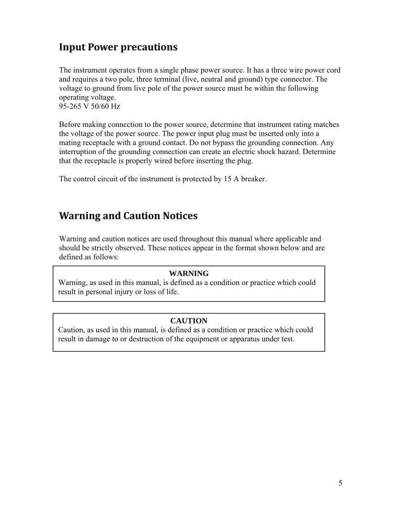
Input Power precautions The instrument operates from a single phase power source. It has a three wire power cord and requires a two pole, three terminal (live, neutral and ground) type connector. The voltage to ground from live pole of the power source must be within the following operating voltage. 95-265 V 50/60 Hz Before making connection to the power source, determine that instrument rating matches the voltage of the power source. The power input plug must be inserted only into a mating receptacle with a ground contact. Do not bypass the grounding connection. Any interruption of the grounding connection can create an electric shock hazard. Determine that the receptacle is properly wired before inserting the plug. The control circuit of the instrument is protected by 15 A breaker.
Warning and Caution Notices Warning and caution notices are used throughout this manual where applicable and should be strictly observed. These notices appear in the format shown below and are defined as follows:
WARNING Warning, as used in this manual, is defined as a condition or practice which could result in personal injury or loss of life.
Caution, as used in this manual, is result in damage to or destruction o
CAUTION defined as a condition or practice which couldf the equipment or apparatus under test.
5
6
Introduction
Megger MCT1605 test is a lightweight, portable unit for shop and field testing of current transformers using IEEE C57.13.1 method. The unit performs excitation, ratio and polarity test by providing a variable output voltage up to 1600 V AC. It will calculate the rated knee point in compliance with IEEE C57.13.1, IEC 60044-1, and IEC 60044-6. MCT1605 test set provides the flexibility of both automatic as well as manual testing. It utilizes the latest DSP technology for testing single and multi-ratio CT’s. The test set can also perform DC insulation resistance test on CT’s to verify the condition of winding to winding and winding to ground insulation. All three, excitation, ratio and polarity tests can be performed with same connection settings without changing any leads. Current Transformers can be tested in their equipment configuration, such as being mounted in transformers, oil circuit breakers or switchgear. This eliminates the need to remove CT’s from switchgear. It is necessary for the equipment to be denergized and totally isolated from the electrical system prior to testing. MCT1605 performs the tests on CT’s to assure that CT’s are of marked ratio and polarity and would perform satisfactorily as designed once put in service. Excitation and burden test ensures that CT’s are of correct accuracy rating and is capable of supplying the known current at stated accuracy. The results obtained from ratio, polarity and excitation tests can be compared with name plate data and manufacturer’s curve to verify the accuracy of the CT under test. The results of the test are displayed on 6.5 inch daylight readable color LCD screen. Ratio and polarity test results can be read right off the screen without any need for calculations. Multiple saturation curves with knee points are shown on the same display for comparison and analysis purpose. MCT1605 can be operated either stand alone or remotely through computer using Power DB lite software. All the test results can either be stored to unit’s internal memory or can be transferred to computer using a thumb drive, through one of the available USB port on the unit.

7
Key Features include:
• User friendly operation, simple connections • One button automated testing • CT ratio knee point saturation, polarity and phase deviation test • Displays multiple instantaneous saturation curves with knee point • Dual lead set, to minimize the effect of voltage drop in leads • Variable 1600 VAC saturation test voltage • Inbuilt 1000V DC Insulation tester • Winding Resistance measurement • Automatic and manual testing selectable • Emergency stop button • Automatically demagnetizes CT after testing • Large , easy to read, color LCD screen • Qwerty keypad for fast data entry • “Save and print later” with USB stick • Store up to 512 test results • Power DB lite software for remote operation

8
Preparation for use
Receiving Instructions Contents of MCT1605 kit Item (Qty.) Cat No. MCT1605 Current Transformer Saturation, Ratio and Polarity Test set MCT1605 Line cord, North America (1ea.) 620000 Line cord, International color coded wire (1ea.) 15065 Test Lead, H1 and H2 40ft. (1ea.) 620148 Test Lead, X red, 20ft., (1ea.) 2000-753 Test Lead, X green, 20ft., (1ea) 2000-747 Test Lead, X yellow, 20ft., (1ea) 2000-748 Test Lead, X blue, 20ft., (1ea) 2000-749 Test Lead, X white, 20ft., (1ea) 2000-746 Gnd lead, green with yellow, with large ground clip, 20ft., (1ea) 620151 Large Test clip, red, 40mm opening, (1ea.) 640266 Large Test clip, black, 40mm opening, (1ea.) 640267 Alligator clip, red, 4.1 mm, (1ea.) 684006 Alligator clip, black, 4.1 mm, (1ea.) 684007 Alligator clip, white, 4.1 mm, (1ea.) 90000-882 Alligator clip, green, 4.1 mm, (1ea.) 90000-883 Alligator clip, yellow, 4.1 mm, (1ea.) 90000-884 Alligator clip, blue, 4.1 mm, (1ea.) 90000-885 Soft side lead case 90000-165 USB memory stick 830029 Instruction book 80513 Power DB Lite DB0001 Check the equipment received against the packing list to ensure that all the materials are present. Notify Megger of any shortages. Telephone 1-800-723 2861 and ask for Dallas customer service department. Examine the instrument for damage received in transit. If damage is discovered, file a claim with the carrier at once and notify Megger or it’s nearest authorized sales representative, giving a detailed description of the damage. Assembly and Installation MCT1605 has been thoroughly tested and inspected to meet rigid specifications before being shipped. The unit is read for use without any need of assembly or any installation procedure. Follow the instructions in this manual to understand the controls and operations of the unit before setting it up for performing the tests. Supply Voltage Unit operates on a single phase AC power source .The input operating voltage should be between the following limits. 95-265 V 50-60 Hz 15A max. Please refer to Input power precautions in safety section for detailed description of input power requirements. Operating System Unit works on VX Work’s operating system.
9
Basic Theory General The purpose of this section is to explain the basic theory of the following tests and to guide the operator for making appropriate measurements with MCT1605. Following tests can be performed by MCT1605.
• Ratio test • Polarity Test • Excitation Test • DC Insulation Resistance Test • Winding Resistance Test • Burden Test
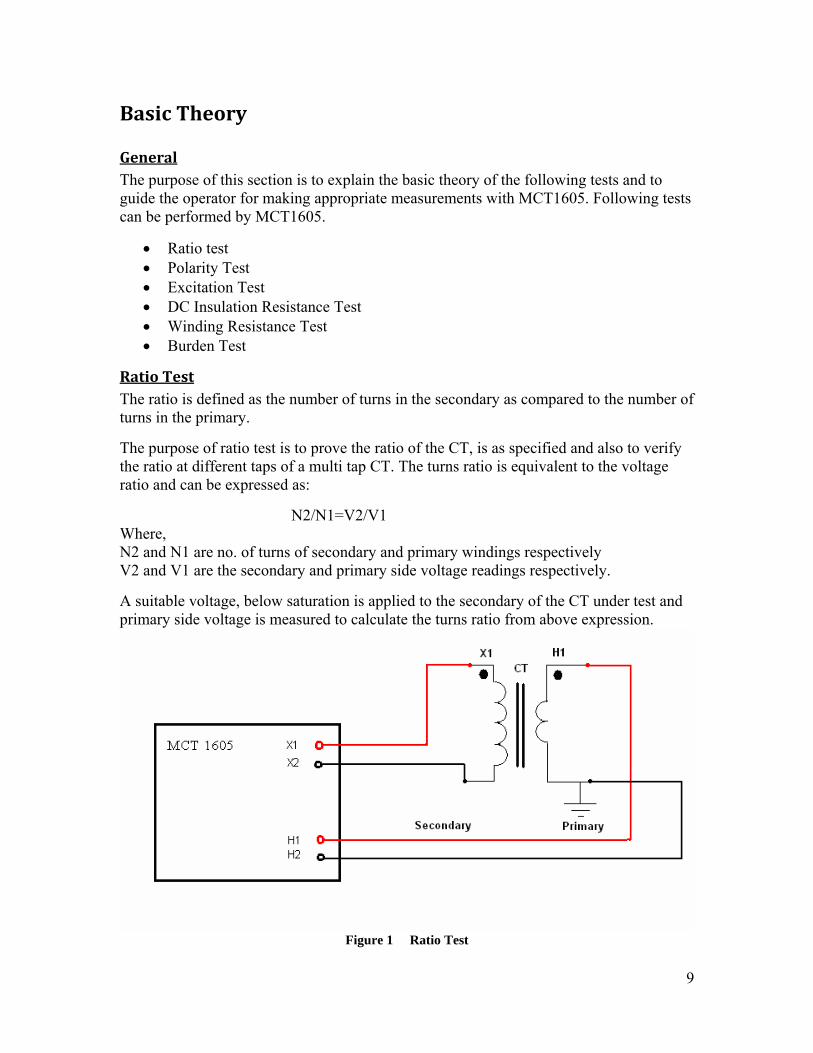
Ratio Test The ratio is defined as the number of turns in the secondary as compared to the number of turns in the primary. The purpose of ratio test is to prove the ratio of the CT, is as specified and also to verify the ratio at different taps of a multi tap CT. The turns ratio is equivalent to the voltage ratio and can be expressed as: N2/N1=V2/V1 Where, N2 and N1 are no. of turns of secondary and primary windings respectively V2 and V1 are the secondary and primary side voltage readings respectively. A suitable voltage, below saturation is applied to the secondary of the CT under test and primary side voltage is measured to calculate the turns ratio from above expression.
Figure 1 Ratio Test

10
MCT1605 performs the ratio test automatically by either selecting Saturation test or Ratio and polarity test. User can also select manual Ratio test by selecting manual option and controlling the secondary applied voltage.
CAUTION In the manual operation, do NOT apply the voltage high enough to the secondary of CT that would cause the CT to saturate; otherwise the readings won’t be accurate.
Polarity Test The Polarity test proves that the predicted direction of secondary CT current (leaving) is correct for a given direction of primary current (entering).
Polarity marks designate the relative instantaneous directions of the currents. At the same instant of time that the primary current is entering the primary terminal the corresponding secondary current is leaving the similarly marked secondary terminal. A CT under test is supposed to have correct polarity if instantaneous current direction for primary and secondary current is opposite to each other.

11
Figure 2 Polarity Test Same connection settings as for Ratio test can be used for performing Polarity test. The two non polarity marks are shorted together internally and potential is measured across the two polarity mark points. For correct polarity, primary winding voltage will be in-phase with secondary winding voltage, with a phase angle difference of zero or close to that. A CT with reverse polarity would read the sum of the two primary and secondary voltages indicating a phase difference of approximately 180 degrees. MCT1605 performs this test in automated fashion and display the result as either Polarity correct or incorrect. Excitation Test IEEE defines the saturation as “the point where the tangent is at 45 degrees to the secondary exciting amperes”. Also known as “knee” point. This test verifies that the CT is of correct accuracy rating, has no shorted turns in the CT and no short circuits are present in the primary or secondary windings of the CT under test. A typical excitation curve for C class current transformer is shown in figure below.

12
Figure 3 Excitation Curve
An Ac voltage is applied to the secondary winding of the CT. The voltage applied to the secondary winding of the CT is increased slowly automatically by the test set. Voltage and current readings for the secondary winding of CT are stored in the internal memory. Test set automatically determines the “Knee” point as per selected standard by observing a small voltage increase causing a large increase in current. The excitation curve around the points where current jumps up for a small increase of voltage; is very important for comparison of curves with published curves or similar CT curves. MCT1605 plots the saturation curve on the LCD display screen. Once a knee point is determined by the test set, it will also display the corresponding saturation voltage and saturation current on the display screen. Multiple CT saturation curves can be plotted on the same screen either for multi taps or for comparison of similar type CT’s. The excitation test results should be compared with published manufacturer’s data or previous recordings to determine any deviations from previously obtained curves. The unit automatically demagnetizes the CT after performing the saturation test by slowing ramping down the secondary voltage all the way back to Zero. It is advisable to demagnetize the CT before performing any test that requires accurate measurements. Please refer to the section of CT Demagnetization for details.

13
Insulation Resistance Test The insulation between the windings and winding to ground should be checked while performing a comprehensive CT test. The test set has inbuilt 1kV DC insulation tester that is used for measurement of insulation resistance. The following connection needs to be made before performing an Insulation test on CT. Short the primary winding of the CT under test by shorting H1 and H2. Short the secondary winding of the CT under test by shorting X1 and X2-X5 Note: MCT1605 does the above two steps automatically. User doesn’t have to perform the shorts externally as unit does that automatically internally. Remove the neutral ground and isolate the CT from any associated burden. After the shorts, it will be a three terminal specimen.
Figure 4 Insulation Resistance Test
Three tests are performed to determine the condition of the insulation of the CT under test.
• Primary to secondary: Checks the condition of insulation between high to low • Primary to ground: Checks the insulation between high to ground • Secondary to ground: Checks the insulation between low to ground.
The DC test voltage is automatically ramped up slowly and the insulation reading in (M) ohms is displayed on the LCD display screen in digital format. The measured values should be compared with similar readings obtained previously and a large deviation should call for further investigation. Any reading in M ohms is considered to be a good insulation. The minimum insulation resistance that is accepted is 1 M ohms. More than a no., it’s the trending of insulation test results that gives the true condition of CT insulation.
Insulation readings are greatly affected by the temperature. Should a reading be compared to previously taken readings, proper correction factors need to be applied, if taken under different temperature conditions before drawing any conclusion. Insulation resistance readings should remain fairly constant over a period of time. A sharp dip in trending of insulation resistance values, point towards insulation degradation and further investigation is warranted to diagnose the problem.
14
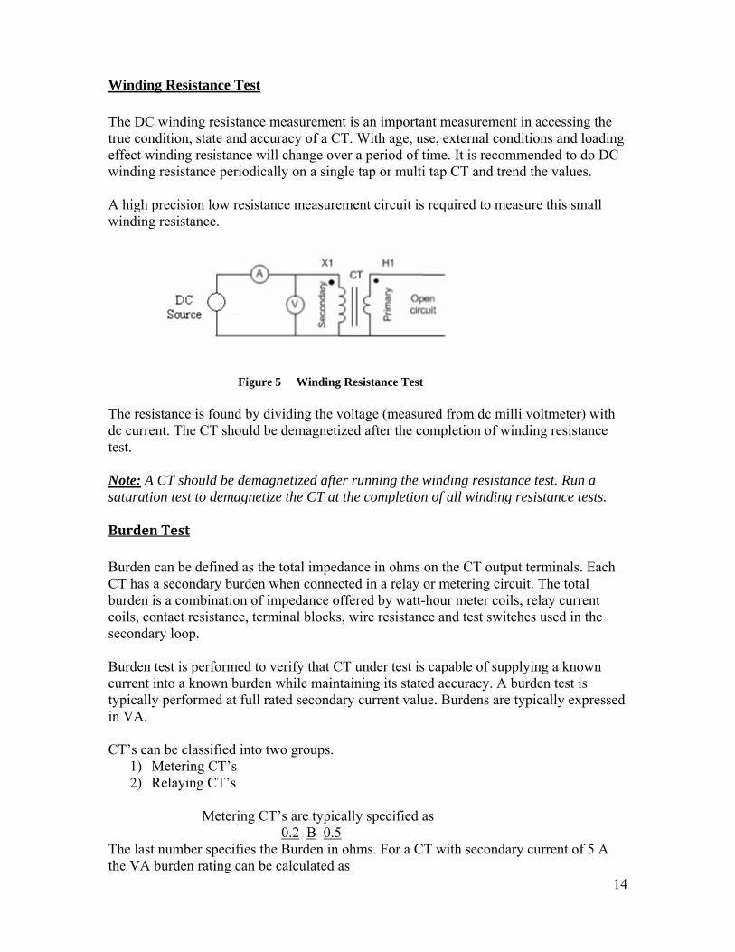
Winding Resistance Test The DC winding resistance measurement is an important measurement in accessing the true condition, state and accuracy of a CT. With age, use, external conditions and loading effect winding resistance will change over a period of time. It is recommended to do DC winding resistance periodically on a single tap or multi tap CT and trend the values. A high precision low resistance measurement circuit is required to measure this small winding resistance.
Figure 5 Winding Resistance Test
The resistance is found by dividing the voltage (measured from dc milli voltmeter) with dc current. The CT should be demagnetized after the completion of winding resistance test. Note: A CT should be demagnetized after running the winding resistance test. Run a saturation test to demagnetize the CT at the completion of all winding resistance tests. Burden Test Burden can be defined as the total impedance in ohms on the CT output terminals. Each CT has a secondary burden when connected in a relay or metering circuit. The total burden is a combination of impedance offered by watt-hour meter coils, relay current coils, contact resistance, terminal blocks, wire resistance and test switches used in the secondary loop. Burden test is performed to verify that CT under test is capable of supplying a known current into a known burden while maintaining its stated accuracy. A burden test is typically performed at full rated secondary current value. Burdens are typically expressed in VA. CT’s can be classified into two groups.
1) Metering CT’s 2) Relaying CT’s
Metering CT’s are typically specified as 0.2 B 0.5The last number specifies the Burden in ohms. For a CT with secondary current of 5 A the VA burden rating can be calculated as
15
VA= Voltage * Current = (Current) 2 * Burden = (5)2 * 0.5 =12.5 VA Relaying CT’s are typically specified as 10 C 400 The last number specifies the max. Secondary voltage at 20 times the rated secondary current without exceeding the 10 % ratio error. For a CT with secondary current rated at 5 A, 20 times rated current secondary current would give a burden of 4 ohms. Burden= 400/ (20*5) = 4 ohms Burden in VA can be specified as VA = Voltage * Current = (Current) 2 * Burden = (5)2 * 4 =100 VA CT’s are expected to provide the secondary output current based upon their accuracy class. If a CT is not properly sized based upon secondary loop burden, it may result in decrease in CT secondary current. Burden test is important to verify that CT is supplying current to a circuit with burden that does not exceed its burden rating. A detailed description of how to perform a burden test with MCT1605 is given in the test procedure

Description of Controls and Indicators
7
3
14
6
55
4
0 1 3
1 Input A2 ON/OF3 High vo4 Connec5 Connec6 Ground7 High vo8 Functio9 QWER
8
C PowF ltage Otions fotion for connecltage On contrTY key
9
er 1 1N indicator 1r X winding 1 H Winding 1tions 1N indicator 1
ols 1pad
12
10 Navigati1 Enter Bu2 TEST bu3 Manual v4 Emergen5 USB stor6 Ethernet 7 LCD dis
1
16
on/Scroll button tton tton oltage controls cy stop button age (2) port play screen
1
7
6
6
1
1
1
2
1

17
Connections: 1. Input power: Receptacle for connecting the test set to an AC power source. Rating
for voltage input is 95-265 V, 50/60 Hz. 2. ON/OFF: Two pole, magnetic main circuit breaker controls the power to the test set
and provide short circuit and overload protection.
CAUTION Caution symbols are appropriately marked on the unit for input and output terminals. Follow the symbols to prevent any accidental electric shock.
3. Insulation Tester: 1000V DC output for performing Insulation test. Outputs are marked as positive (red) and negative (blue).
4. X winding connection: Dual point connection to X winding of the current
transformer under test. A maximum of 1600V AC is available from this output. 5. H winding Connection: Connection to H winding of the current transformer. H1,
H2 connections are used to measure the voltage across the H winding during test operation.
WARNING Appropriate warning symbols are marked on the unit, indicative of possible source of electric shock. Follow the symbols while operating the unit.
6. Ground Connection: This wing nut is used to connect the test set to station ground. Indicators: 7. High Voltage indicators: Red color LED’s indicating the presence of high voltage at
the outputs of the unit.
WARNING High voltage is present at the X1, X2 output terminals of the unit whenever the two red color LED lights are flashing.
Controls: 8. Function controls: F1 to F6 function keys are used to select different options in
menu screen. F1- Back to test /Load test /Update software/Select voltage and current F2- Delete file/Range selection/Tap ratio F3- Rename the File F4- Copy the File to USB/Print F5- Save results F6- Main menu

18
9. QWERTY Keypad: It is used to enter alpha numeric data for test report. Function
buttons are used to access different control options in various test screens. 10. Navigation Button: These arrow keys are used to scroll sideways and up/down for
accessing different menu options. 11. Enter: This is used to activate a particular selection in the menu options. 12. Test: This is used to initiate and terminate the testing. 13. Manual voltage controls: The potentiometer knob is used for manual control of
output voltage from test set to the secondary of the CT. Press the knob for fast variation in voltage.
14. Emergency Stop Button: This red push button interrupts testing. When pressed, the
switch is locked in OFF position. To reset the switch, turn the button in the direction indicated by the arrows.
Communication & Storage: 15. USB storage: Two USB ports are available for transfer of data from internal
memory to any external memory device. User can connect optional printer to one of the USB port for printing of test results. 16. Ethernet port: Ethernet port is used for connection of unit to the computer for
remote operation. Display: 17. LCD display screen: The 6.5” large graphical display provides easy to read test
results and CT saturation curve plots.

19
Operation and Controls
The MCT1605 works on “VX Works” operating system. At the boot up of the test set, Main Menu screen will show up. Main menu:
Main menu is the home screen of the test set. All the tests and settings for the unit can be accessed from this screen. With the help of navigation button and enter key one can select the desired operation. Following are the nine user selectable operation. Nameplate Information Saturation Test File Manager Ratio Test System Defaults Insulation Test Manual Winding Resistance Test Configuration Refer to each menu item below for detailed description
20
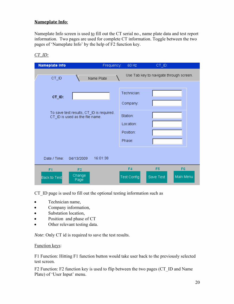
Nameplate Info: Nameplate Info screen is used to fill out the CT serial no., name plate data and test report information. Two pages are used for complete CT information. Toggle between the two pages of ‘Nameplate Info’ by the help of F2 function key. CT_ID:
CT_ID page is used to fill out the optional testing information such as
• Technician name, • Company information, • Substation location, • Position and phase of CT • Other relevant testing data.
Note: Only CT id is required to save the test results. Function keys: F1 Function: Hitting F1 function button would take user back to the previously selected test screen.
F2 Function: F2 function key is used to flip between the two pages (CT_ID and Name Plate) of ‘User Input’ menu.

21
F4 Function: This key is used to configure the saturation, ratio and insulation test on a CT. F5 Function: This key would save the test results to internal memory of the test set with file name as CT id.
F6 Function: It is used to return back to the main menu or home screen. Name Plate:
Nameplate page is used to fill out the Name plate data of CT under test.
• Manufacturer: By using the tab button, place the cursor in this column and enter the manufacturer of the CT.
• Serial No: Fill CT serial no. from the nameplate of the CT under test.
• Type: Select the appropriate type of CT from available selection. a) Bar Type b) Window Solid Type c) Window Split Core
• Style: The style of CT can be entered in this column.
• Voltage rating: Voltage rating can be obtained from CT nameplate.

22
• Accuracy Class Select the CT accuracy class from available options aa) C10 h) T10 b) C20 i) T20 c) C50 j) T50 d) C100 k) T100 e) C200 l) T200 f) C400 m) T400 g) C800 n) T800
• Ratio: For a multi- tap CT, different tap ratios can be obtained from nameplate and can be entered in nameplate screen.
• Temperature & Humidity: If known, environmental conditions such as temperature and humidity can be entered.
Note: All the information in Nameplate screen is optional. It is not required to perform a test on CT. Only CT ID is required for storage of results.
Function keys: F1 Function: Hitting F1 function button would take user back to the previously selected test screen.
F2 Function: F2 function key is used to flip between the two pages (CT_ID and Name Plate) of ‘User Input’ menu.
F4 Function: This key is used to configure the saturation, ratio and insulation test on a CT.
F5 Function: This key would save the test results to internal memory of the test set with file name as CT id.
F6 Function: It is used to return back to the main menu or home screen.

23
File Manager:
File manager screen is used to view and access the stored test results. All stored test results are displayed in alphabetical order along with date and time stampings. Test results are stored with the file name as CT ID and extension as “.tst”. MCT1605 test set can store up to 3000 or more test results in its internal memory. Function buttons are used to recall, delete or transfer the test results. Function keys:
F1 function: This key is used to load the test results on the MCT display screen.
• Select the desired test results by highlighting it. • Hit F1 function key. • A message will pop up indicating that a particular test result has been loaded.
• The screen will go back to the main menu or home screen. • Select the desired test to view the readings or curve.

24
F2 function: This key is used to delete the previously stored test results from internal memory of the unit.
• Select the desired test to be deleted. • Hit F2 function key. • A window will come up for confirmation to delete the test result.
• Hit ‘YES’. • Test result is now deleted.
F3 function: This key is used to rename the already stored file.
• Select the file to be renamed. • Hit F3 function key. • A window will come up with column to put a new file name. Enter the new file
name.
• Hit OK. • File name is now changed.
F4 function: This key is to copy the stored test results from internal memory to external memory device like USB stick.
• Select the file to be transferred. • Hit F4 function key. • The unit will try to detect the external memory device. If there is no memory stick,
following message will come up.

25
• If external memory device is present, following message will be displayed, indicating that data has been copied to the external memory device.
• Hit Ok. Note: Stored test results are copied NOT transferred to the external memory device. In order to free up the internal memory of the test set, user have to delete the test results.
F5 function: This key is used to print out the list of all stored test files inside the unit.
F6 function: This key is used to return back to main menu or home screen.
26
System Default:
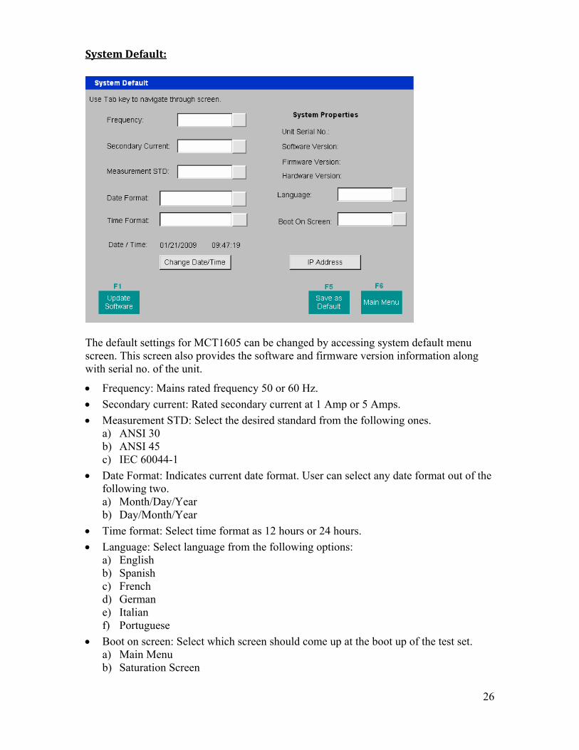
The default settings for MCT1605 can be changed by accessing system default menu screen. This screen also provides the software and firmware version information along with serial no. of the unit.
• Frequency: Mains rated frequency 50 or 60 Hz.
• Secondary current: Rated secondary current at 1 Amp or 5 Amps.
• Measurement STD: Select the desired standard from the following ones. a) ANSI 30 b) ANSI 45 c) IEC 60044-1
• Date Format: Indicates current date format. User can select any date format out of the following two. a) Month/Day/Year b) Day/Month/Year
• Time format: Select time format as 12 hours or 24 hours.
• Language: Select language from the following options: a) English b) Spanish c) French d) German e) Italian f) Portuguese
• Boot on screen: Select which screen should come up at the boot up of the test set. a) Main Menu b) Saturation Screen
27
Change Date/Time: This button would let user to change current date and time. Function keys System Defaults:
F1 Function: Hit F1 key to update the software. Unit look for the latest software files in the external memory device connected to the USB port.
F5 Function: Hit F5 function key to save the settings on this screen.
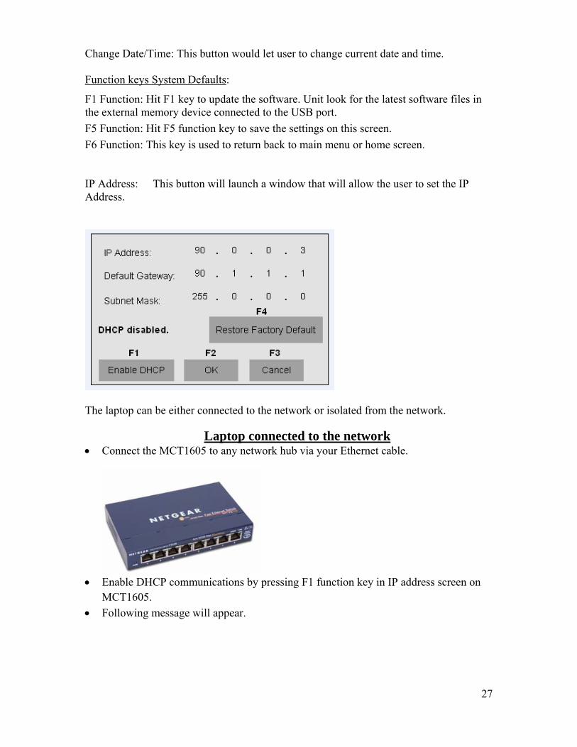
F6 Function: This key is used to return back to main menu or home screen. IP Address: This button will launch a window that will allow the user to set the IP Address.
The laptop can be either connected to the network or isolated from the network.
Laptop connected to the network • Connect the MCT1605 to any network hub via your Ethernet cable.
• Enable DHCP communications by pressing F1 function key in IP address screen on
MCT1605. • Following message will appear.

28
• Based upon server settings either of the following messages will appear.
Condition I
THIS WILL AUTOMATICALLY ASSIGN IP ADDRESS TO THE UNIT
• After enabling the DHCP, open the Power DB lite and select MCT-16xx instrument.

29
• Check Use Ethernet box and leave the Ethernet field blank.
• Hit OK. • Initialize the instrument by hitting the highlighted button below in Power DB.
• OK message would pop up in Power DB lite screen • This would establish the communication with the MCT1605 test set and now
it is ready for remote control operation. Condition II
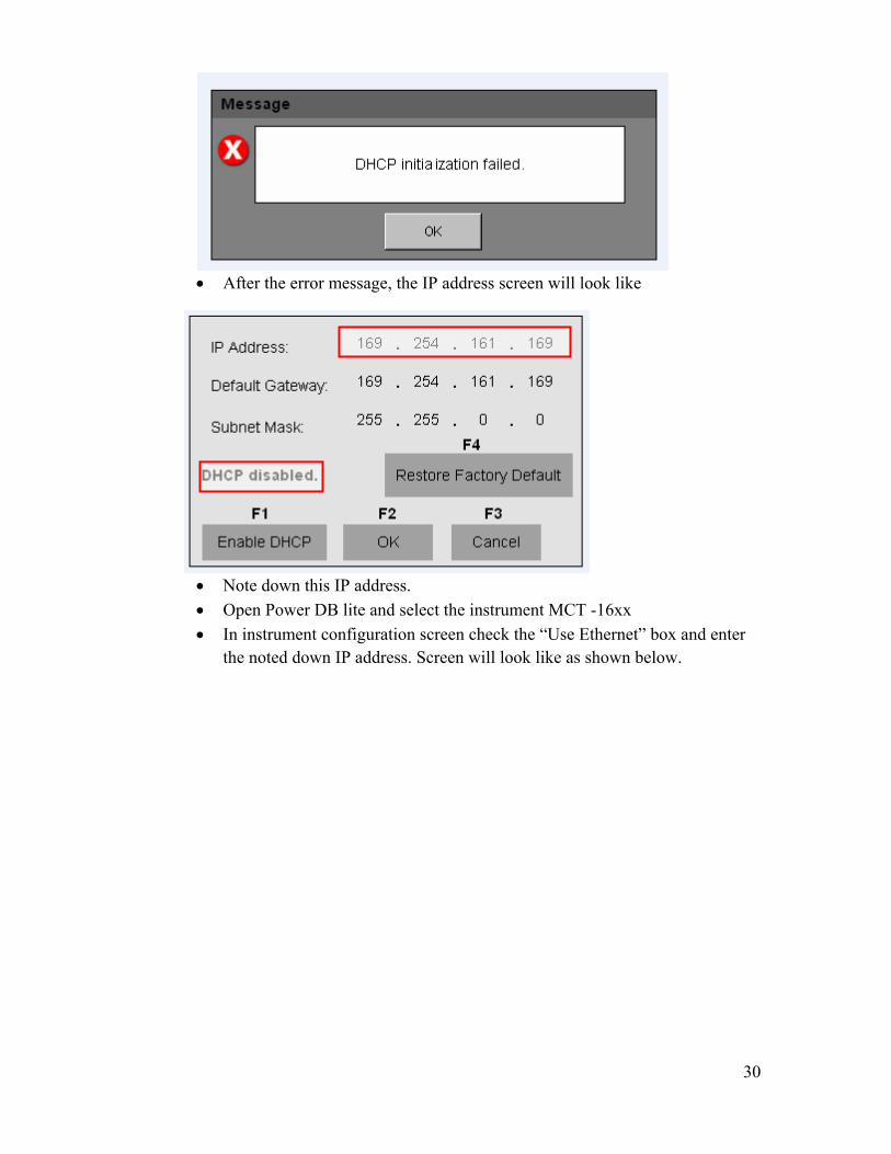
• IF DHCP initialization fails after pressing F1 function key then following message will appear.
30
• After the error message, the IP address screen will look like
• Note down this IP address. • Open Power DB lite and select the instrument MCT -16xx • In instrument configuration screen check the “Use Ethernet” box and enter
the noted down IP address. Screen will look like as shown below.

31
• Hit OK. • Initialize the instrument by hitting the highlighted button below in Power DB.
• OK message would pop up in Power DB lite screen
• This would establish the communication with the MCT1605 test set and now it is ready for remote control operation.
Laptop not connected to the network
If laptop is not connected to the network, user can establish communication using any one method shown below:

32
Method I:
• Hit F1 function key in IP address screen to initialize DHCP communications • Since, computer is not connected to the network, it will fail DHCP
initialization.
• After the error message, the IP address screen will look like
• Note down this IP address. • Open Power DB lite and select the instrument MCT -16xx • In instrument configuration screen check the “Use Ethernet” box and enter
the noted down IP address. Screen will look like as shown below.

33
• Hit OK. • Initialize the instrument by hitting the highlighted button below in Power DB.
• OK message would pop up in Power DB lite screen
• This would establish the communication with the MCT1605 test set and now it is ready for remote control operation.
Method II: • Click on IP address in system default screen . It will show the factory default IP
address.

34
• Go to control panel of your computer and click on Network Connections. • Double click on local area connection and hit on properties.
• Following window will open up. Scroll down and double click on Internet Protocol (TCP/IP)

35
• Internet protocol properties window will open up. • Select “Use the following IP address” radio button. • Enter the IP address and subnet mask as shown below.
Make a note that it is
• Hit OK. • Open Power DB lite and select the instrument MCT -16xx • In instrument configuration screen check the “Use Ethernet” box and enter
the noted down IP address. Screen will look like as shown below.

36
• Hit OK. • Initialize the instrument by hitting the highlighted button below in Power DB.
Make a note that it is
• OK message would pop up in Power DB lite screen
• This would establish the communication with the MCT1605 test set and now it is ready for remote control operation.

37
Manual:
MCT1605 gives user the option of manual testing on current transformers. Manual screen is used for performing a manual test. In manual mode, manual voltage controls knob is used for application of test voltage to the secondary of CT under test.
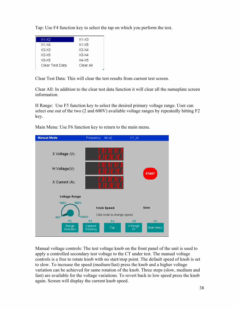
Range Selection: Use F2 function key to select the desired secondary voltage range. User can select any one out of the four (40,160,800 and 1600V) available voltage ranges by repeatedly hitting F2 key. Capture Reading: Use F3 function key to freeze the current reading and calculate the turns ratio. All control knobs and function keys will be frozen except the F3 or Release function key. The ratio and respective voltages will be displayed on the screen as shown below. Release: After a reading has been captured use F3 function key to release the control knobs and other function keys.
38
Tap: Use F4 function key to select the tap on which you perform the test.
Clear Test Data: This will clear the test results from current test screen. Clear All: In addition to the clear test data function it will clear all the nameplate screen information. H Range: Use F5 function key to select the desired primary voltage range. User can select one out of the two (2 and 600V) available voltage ranges by repeatedly hitting F2 key. Main Menu: Use F6 function key to return to the main menu.
Manual voltage controls: The test voltage knob on the front panel of the unit is used to apply a controlled secondary test voltage to the CT under test. The manual voltage controls is a free to rotate knob with no start/stop point. The default speed of knob is set to slow. To increase the speed (medium/fast) press the knob and a higher voltage variation can be achieved for same rotation of the knob. Three steps (slow, medium and fast) are available for the voltage variations. To revert back to low speed press the knob again. Screen will display the current knob speed.

39
Secondary (X) Voltage: The applied secondary test voltage is displayed on the screen in digital readout form. Primary (H) Voltage: The measured primary voltage is displayed on the screen in digital readout form. Secondary(X) Current: The secondary current is displayed for user reference to monitor while performing ratio and saturation tests. Test Configuration:
This screen is used to configure and select the tests to be performed on different taps of the CT. Tap Selection: Select different taps of CT on which you want to perform the tests using the check boxes. All Taps: Selecting all taps would check all the boxes in that column. For instance selecting all taps in saturation test column would select all taps and test set will perform saturation test on all the checked taps. Saturation: Checking box in this column in front of any tap would enable the saturation test for that particular tap.

40
Ratio: Checking box in this column in front of any tap would enable the ratio test for that particular tap. Winding resistance: Checking box in this column in front of any tap would enable the winding resistance test for that particular tap. Voltage range: Voltage range enables you to select the desired voltage range at which you want to run the test. For saturation test four available voltage ranges are: a) 40 V b) 160 V c) 800 V d) 1600 V For Insulation resistance test, two available voltage ranges are: a) 500 V b) 1000 V Insulation resistance: Three different tests can be selected for insulation resistance based upon between which two points you want to check the insulation.
• Primary to Secondary • Primary to Ground • Secondary to Ground
Once all the desired tests are selected in the test configuration screen, all the tests would run in sequential order automatically, when you hit ‘Run’ button (F1 key). After all the selected tests are finished, user can save the results by entering in the CT ID. Function keys: Function F1: Hit F1 to run the all the selected tests sequentially and automatically. Function F5: Hit F5 to go to nameplate screen and enter the CT nameplate information. Function F6: Hit 5 to go back to main menu.

41
Saturation Test: Saturation test menu screen is used to perform a saturation test on CT. At the end of test, saturation curve, measured ratio and polarity test results are displayed for the CT under test.
X Voltage (V): It displays the real time voltage readings of the secondary X winding while the test is in progress. X Current (A): It displays the real time current readings for the secondary X winding while the test is in progress. H Voltage (V): It displays the real time voltage readings of the primary H winding while the test is in progress. Saturation Curve: The excitation curve is Log-Log curve with secondary current on X coordinate and secondary voltage on Y coordinate. Ratio: At the completion of test, the measured ratio is compared with expected ratio (obtained based upon user input) and a percent error in Ratio is determined by following formula.
[(Expected ratio-Measured ratio)/ Expected ratio] * 100
Test voltage: It displays the selected test voltage. User can select any one out of four available test voltages (40,160,800 and 1600).

42
Polarity: Unit automatically determines the polarity connections and displays the result as either polarity Correct or Incorrect. The phase angle deviation between the secondary and primary voltage is also displayed along with polarity. Saturation points: The unit automatically determines the knee point based upon the user selected standard (ANSI 30, ANSI 45 or IEC 60044-1). Saturation voltage and saturation current corresponding to that knee point are displayed along with other results at the completion of the test. Max limit: Hit F1 function button to select the desired test voltage. Four test voltages available are 40V, 160V, 800V and 1600 V. For instance, on selecting a test voltage of 800V, the unit will automatically vary the voltage from 0 to 800V to determine the saturation curve and knee point. If the selected voltage is not sufficient enough to determine the required parameters, the unit will display the following error message.
Select a higher test voltage range and perform the test again. Note: Appropriate voltage range can be selected by knowing the accuracy class of CT under test. Tap ratio: Hit F2 function to put the expected tap ratio of the CT under test. Following pop up will come up on hitting the F2 button.
Select the desired Tap and a window will pop up to enter the tap ratio.

43
Use tab button and numeric keypad to enter the desired tap ratio. Hit the enter button to accept a value or on the OK button to finish. Note: To clear Nameplate data and all test data, use “clear all” option in Tap/Ratio screen. To save the Nameplate data, clear the test screens and clear off previous test results, use “clear Test Data” option in Tap/Ratio. Print result: Hit F4 function button to print out the saturation test results. Results will be printed on 8” by 11” paper through an external printer. Save result: Hit F5 function button to store the saturation test results in the internal memory of the unit. Only CT id is required to store the test results. Main menu: Hit F6 button to return to main menu or home screen of the unit. Ratio Test:

44
Ratio menu screen is used to perform the ratio and polarity test. Measured ratio, polarity, test voltage and current are displayed at the end of the test. Unit automatically selects the voltage range for the ratio test. X Voltage (V): It displays the real time applied voltage to the secondary X winding of the CT under test. H Voltage (V): It displays the real time measured voltage of the primary H winding of the CT under test. Tap: Displays the selected tap of the CT. Ratio: At the completion of test, the measured ratio is compared with expected ratio (obtained based upon user input) and a percent error in Ratio is determined by following formula.
[(Expected ratio-Measured ratio)/ Expected ratio] * 100
Test voltage: Unit automatically applies the required voltage for the ratio test. It displays secondary test voltage at the completion of test. Test current: Unit continuously monitors the secondary excitation current and displays test current at the end of the ratio test. Polarity: Unit automatically determines the polarity connections and displays the result as either polarity Correct or Incorrect. The phase angle deviation between the secondary and primary voltage is also displayed along with polarity. Tap ratio: Hit F2 function to put the expected tap ratio of the CT under test. Following pop up will come up on hitting the F2 button.
Select the desired Tap and a window will pop up to enter the tap ratio.

45
Use tab button and numeric keypad to enter the desired tap ratio. Hit the enter button to accept a value or on the OK button to finish. Note: To clear Nameplate data and all test data, use “clear all” option in Tap/Ratio screen. To save the Nameplate data, clear the test screens and clear off previous test results, use “clear Test Data” option in Tap/Ratio. Print result: Hit F4 function button to print out the ratio and polarity test results. Results will be printed on 8” by 11” paper through an external printer. Save result: Hit F5 function button to store the ratio and polarity test results in the internal memory of the unit. Only CT ID is required to store the test results. Main menu: Hit F6 button to return to main menu or home screen of the unit. Insulation Test:
Insulation test menu screen is used to perform an insulation test between the windings (or windings to ground) of the CT, by applying a 1000 VDC. Insulation resistance can be displayed in (M) ohms, (K) ohms, and ohms. Digital analog indicator: Displays the insulation resistance with a digital pointer on a log scale from 0.01 M ohms to 1000 M ohms.

46
Insulation resistance: Displays the insulation resistance in M ohms on digital read out. Test volt: Select either 500V or 1000V DC test voltage by using function key F1. Test configuration: Select desired test by repeatedly hitting function F2 key. User can select one of the three test mode. a) Primary to Secondary b) Primary to Ground c) Secondary to Ground Tap: Hit F3 function key to select the tap configuration of the CT. This would select if there are 2, 3, 4 or 5 taps on a CT.
Print result: Hit F4 function button to print out the insulation test results. Results will be printed on 8” by 11” paper through an external printer. Save result: Hit F5 function button to store the insulation test results in the internal memory of the unit. Only CT ID is required to store the test results. Main menu: Hit F6 button to return to main menu or home screen of the unit.

47
Winding Resistance Test:
Winding resistance menu screen is used to determine if the dc resistance of the CT secondary winding is within specification or not. A DC current is applied and voltage is measured to determine the winding resistance for the selected tap. After measurement winding resistance is displayed in digital and analog format on the screen. Digital analog indicator: Displays the winding resistance with a digital pointer on a log scale from 0.01 ohms to 100 ohms. Winding resistance: Displays the winding resistance in ohms on digital read out. Tap: Hit F2 function button repeatedly to select the desired tap. This will select the tap on which it will perform the winding resistance measurement. Print result: Hit F4 function button to print out the insulation test results. Results will be printed on 8” by 11” paper through an external printer. Save result: Hit F5 function button to store the insulation test results in the internal memory of the unit. Only CT ID is required to store the test results. Main menu: Hit F6 button to return to main menu or home screen of the unit. Note: A CT should be demagnetized after running the winding resistance test. Run a saturation test to demagnetize the CT at the completion of all winding resistance tests.

48
Burden Test:
Burden menu screen is used to perform a burden test on CT secondary burden. Results are displayed in VA and phase angle. X Voltage (V): It displays the real time measured voltage across the burden of the CT. X Current (A): It displays the applied current (user selected 1A or 5A) to the burden of the CT. Burden VA: Displays the burden on the CT in VA, after the completion of test. PF: Displays ratio of real power to apparent power. Rating: Based upon the CT rating, hit Function F1 to select the current as 1A or 5A. Print result: Hit F4 function button to print out the burden test results. Results will be printed on 8” by 11” paper through an external printer. Save result: Hit F5 function button to store the burden test results in the internal memory of the unit. Only CT id is required to store the test results. Main menu: Hit F6 button to return to main menu or home screen of the unit.

49
Operating Instructions Ratio & Polarity Test: The ratio is defined as the number of turns in the secondary as compared to the number of turns in the primary. N2/N1=V2/V1 Where, N2 and N1 are no. of turns of secondary and primary windings respectively V2 and V1 are the secondary and primary side voltage readings respectively. A suitable voltage, below saturation is applied to the secondary of the CT under test and primary side voltage is measured to calculate the turns ratio from above expression. Connections for the test set:
1. Refer to the safety instructions first before the use of equipment. 2. Verify the Power ON/OFF switch is OFF. Power the test set from a suitable source
of power (95-265 V 50/60 Hz). 3. Connect the ground wing nut to a suitable ground.
WARNING There is always a possibility of voltages being induced at the terminals of the test specimen because of proximity to high voltage energized lines. A residual static voltage charge may also be present at these terminals. Ground each terminal to be tested with a safety ground stick, before making connections.
4. Connect the test set secondary output binding posts X1 X2, X3, X4 and X5 to secondary of the current transformer X1, X2, X3, X4 and X5 (if all taps all are not available on the CT, then connect the ones that are available to the corresponding tap no. on the test set).Observe the polarity marks on the CT (X1 on test set is polarity terminal).
5. Connect the test set primary binding posts H1 and H2 to CT primary bushings H1 and H2.Observe the polarity marks on the CT (H1 on the test set is polarity terminal).
WARNING
The MCT produces high voltages and currents during the performance of tests. DO NOT TOUCH connector clips or test leads while the MCT is performing a test.

50
6. Turn Power ON/OFF switch to ON. 7. After the boot up, select the “Ratio Test” menu from the main screen by using scroll
button. 8. In the ratio screen, hit F2 function button to select the appropriate tap to be tested.
9. Enter the expected nameplate ratio for the desired tap. Toggle through different
columns by using scroll, “TAB” button, or “Enter” button.
Hit “Enter” button on the OK to finish.

51
10. Select the tap configuration before hitting the TEST button. If test button is pressed
before selecting the tap, following message will appear:
11. Hit the “TEST” button to start the test.
12. A dialog box appears for confirmation of the test. Hit TEST button again.
WARNING High Voltage is now present at the terminals of the specimen and in the test leads
13. This will start the test and a warning high voltage symbol will appear on the “test in progress” screen.
14. At any point of time Test can be terminated by hitting the Test button again. Following message will appear.
52
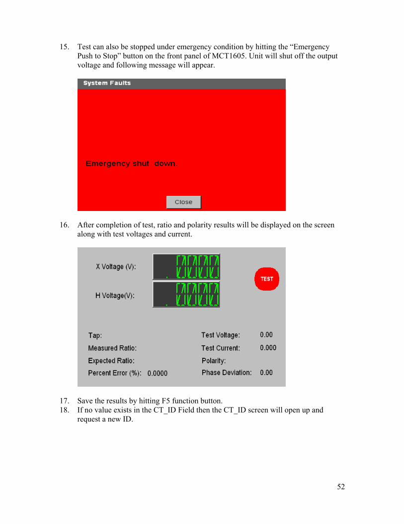
15. Test can also be stopped under emergency condition by hitting the “Emergency
Push to Stop” button on the front panel of MCT1605. Unit will shut off the output voltage and following message will appear.
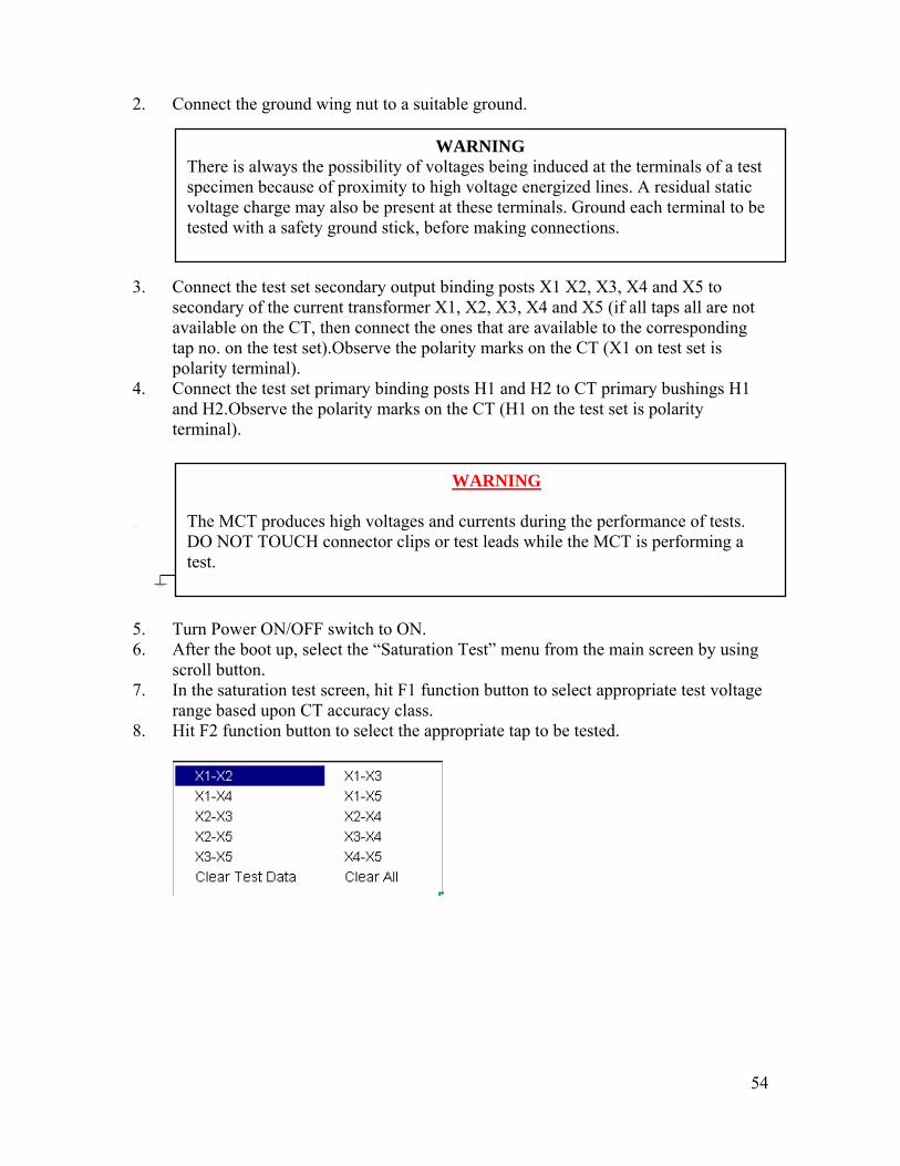
16. After completion of test, ratio and polarity results will be displayed on the screen along with test voltages and current.
17. Save the results by hitting F5 function button. 18. If no value exists in the CT_ID Field then the CT_ID screen will open up and
request a new ID.

53
19. Put in the CT ID information.
20. Hit F1 function button to save or the F2 function button to cancel.
21. If F1 is selected and the file does not already exist the following message will appear indicating that test has been saved. If F2 function button is selected then the user will be returned to previous menu.
22. If the file already exists the test results will be added to the existing file. Saturation Test: IEEE defines the saturation as “the point where the tangent is at 45 degrees to the secondary exciting amperes”. It is also known as “knee” point. This test verifies that the CT is of correct accuracy rating, has no shorted turns in the CT and no short circuits are present in the primary or secondary windings of the CT under test. Connections for the test set: Refer to the safety instructions first before use of the equipment. 1. Verify the Power ON/OFF switch is OFF. Power the test set from a suitable source
of power (95-265 V50/60 Hz).
54
2. Connect the ground wing nut to a suitable ground.
WARNING There is always the possibility of voltages being induced at the terminals of a test specimen because of proximity to high voltage energized lines. A residual static voltage charge may also be present at these terminals. Ground each terminal to be tested with a safety ground stick, before making connections.
3. Connect the test set secondary output binding posts X1 X2, X3, X4 and X5 to secondary of the current transformer X1, X2, X3, X4 and X5 (if all taps all are not available on the CT, then connect the ones that are available to the corresponding tap no. on the test set).Observe the polarity marks on the CT (X1 on test set is polarity terminal).
4. Connect the test set primary binding posts H1 and H2 to CT primary bushings H1 and H2.Observe the polarity marks on the CT (H1 on the test set is polarity terminal).
WARNING
The MCT produces high voltages and currents during the performance of tests. DO NOT TOUCH connector clips or test leads while the MCT is performing a test.
5. Turn Power ON/OFF switch to ON. 6. After the boot up, select the “Saturation Test” menu from the main screen by using
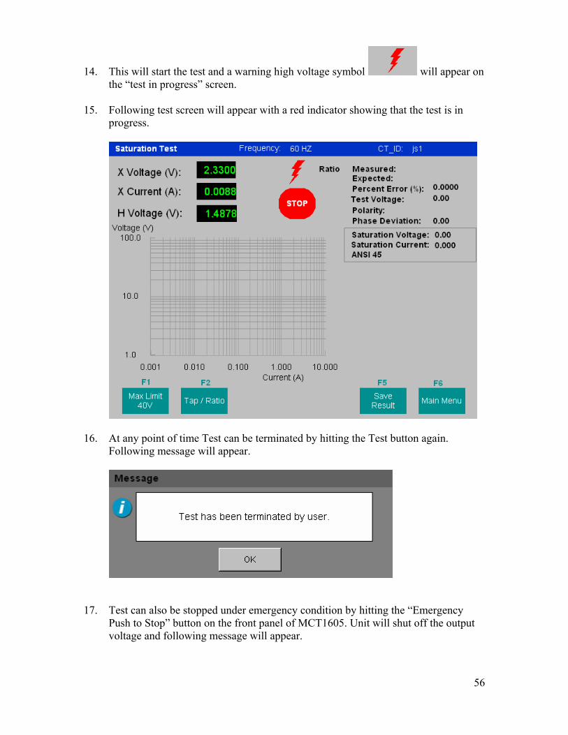
scroll button. 7. In the saturation test screen, hit F1 function button to select appropriate test voltage
range based upon CT accuracy class. 8. Hit F2 function button to select the appropriate tap to be tested.

55
9. Enter the expected nameplate ratio for the desired tap. Toggle through different
columns by using scroll and “TAB” button.
Hit OK to finish.
10. Select the tap configuration before hitting the TEST button. If test button is pressed before selecting the tap, following message will appear:
11. Hit the “TEST” button to start the test. 12. A dialog box appears for confirmation of the test.
13. Hit TEST button again.
WARNING High Voltage is now present at the terminals of the specimen and in the test leads
56
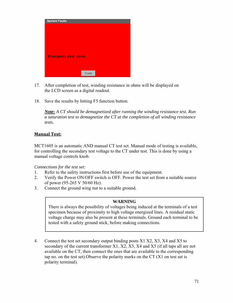
14. This will start the test and a warning high voltage symbol will appear on the “test in progress” screen.
15. Following test screen will appear with a red indicator showing that the test is in progress.
16. At any point of time Test can be terminated by hitting the Test button again.
Following message will appear.
17. Test can also be stopped under emergency condition by hitting the “Emergency Push to Stop” button on the front panel of MCT1605. Unit will shut off the output voltage and following message will appear.

57
18. After completion of test, saturation curve, ratio and polarity results will be displayed on the screen along with test voltages and current.
19. If the selected Test voltage range is not enough to perform the saturation test, following message will appear.

58
20. Select the higher voltage range and perform the Test again. 21. Save the results by hitting F5 function button. 22. If no value exists in the CT_ID Field then the CT_ID screen will open up and
request a new ID.
22 Put in the CT id information. All other information is optional.
23 Hit F1 function button to save or the F2 function button to cancel.
24 If F1 is selected and the file does not already exist the following message will appear indicating that test has been saved. If F2 function button is selected then the user will be returned to previous menu.
25 If the file already exists the test results will be added to the existing file.
Multiple saturation curves for different taps can be plotted on same chart by re running the test. As many as 10 curves can be displayed at one time. Please refer to “How to run multiple saturation tests” below.

59
How to run multiple saturation tests Method I:
• After finishing first saturation test, hit F2 function to select the next tap settings.
• Enter the expected nameplate ratio for the selected Tap.
` Hit OK. • Select the appropriate voltage range by hitting F1 (Max Limit) function button. • Select the tap configuration before hitting the TEST button. If test button is pressed
before selecting the tap, following message will appear:
• Hit the “TEST” button to start the test. • A dialog box appears for confirmation of the test.

60
• Hit TEST button again.
WARNING High Voltage is now present at the terminals of the specimen and in the test leads
• This will start the test and a warning high voltage symbol will appear on the “test in progress” screen.
• If the selected Test voltage range is not enough to perform the saturation test,
following message will appear.
• Select the higher voltage range and perform the Test again. • At the completion of test saturation curve will be displayed on the same graph along
with previous curve(s).
• All the results like ratio, polarity, saturation voltage and current will also be displayed for the current saturation test.

61
• As many as 10 different curves can be plotted on the same graph by repeating the same steps and selecting different CT taps.
• The ratios for different taps are displayed on right hand side of screen in different
colors. Use Tab button to scroll through different ratios and detailed results for that particular Tap.
METHOD II:
• Go to Main menu. • Select Test configuration
• Select the taps on which you want to run the saturation test by checking the boxes
in front of it in the saturation column • Select the desired voltage range at which you perform the test. • Hit F1 function key to run all the selected saturation tests sequentially. Note: Appropriate voltage range can be selected by knowing the accuracy class of CT under test. • The MCT1605 screen would automatically go to the saturation test screen. • Once all the saturation tests are done, it will show the saturation curves along with
ratio and polarity for different taps on the saturation screen. • Hit F5 function key to store the results.

62
DC Insulation Resistance Test: The insulation between the windings and winding to ground should be checked while performing a comprehensive CT test. The test set has inbuilt 1kV DC insulation tester that is used for measurement of insulation resistance. Connections for the test: 1. Refer to the safety instructions first before use of the equipment. 2. Verify the Power ON/OFF switch is OFF. Power the test set from a suitable source
of power (95-265 V 50/60 Hz). 3. Connect the ground wing nut to a suitable ground.
WARNING There is always the possibility of voltages being induced at the terminals of a test specimen because of proximity to high voltage energized lines. A residual static voltage charge may also be present at these terminals. Ground each terminal to be tested with a safety ground stick, before making connections.
4. Connect the test set secondary output binding posts X1 X2, X3, X4 and X5 to secondary of the current transformer X1, X2, X3, X4 and X5 (if all taps all are not available on the CT, then connect the ones that are available to the corresponding tap no. on the test set).Observe the polarity marks on the CT (X1 on test set is polarity terminal).
5. Connect the test set primary binding posts H1 and H2 to CT primary bushings H1 and H2.Observe the polarity marks on the CT (H1 on the test set is polarity terminal).
WARNING
The MCT produces high voltages and currents during the performance of tests. DO NOT TOUCH connector clips or test leads while the MCT is performing a test.

63
6. On any CT insulation tests are performed between three points.
a) Primary b) Secondary c) Ground A three point insulation looks like the diagram below.
Note: User does not have to short the primary or secondary sides of CT; the MCT1605
does that automatically internally. Note: User does not have to make any other connections except as described in step 3, 4
and 5.
7. Remove the neutral ground and isolate the CT from any associated burden. 8. Turn Power ON/OFF switch to ON. 9. After the boot up, select the “Insulation Test” menu from the main screen by using
scroll button. 10. Hit F3 function key to select the tap configuration of CT out of the following:
a)X1-X2 b)X1-X3 c)X1-X4 d)X1-X5 For instance you would select X1-X3 for a CT that has X1, X2 and X3 terminals.
11. Three DIFFERENT tests are performed to determine the condition of the insulation of CT under test. The three tests are:
• First- Primary to Secondary:
Select the primary to secondary test from the insulation test screen (using F2 function key) and also select the desired voltage (using F1 function key). Based upon test selection MCT1605 would automatically know between which two points the voltage needs to be applied.

64
In this test it will apply the voltage between primary and secondary.
• Second- Primary to Ground: Select the primary to ground test from the insulation test screen and also select the
desired voltage. Based upon test selection MCT1605 would automatically know between which two points the voltage needs to be applied.
In this test it will apply the voltage between primary and ground.

65
• Third- Secondary to Ground: Select the secondary to ground test from the insulation test screen and also select
the desired voltage. Based upon test selection MCT1605 would automatically know between which two points the voltage needs to be applied.
In this test it will apply the voltage between secondary and ground.
Note: Refer to the Insulation Test diagram (Figure 9, 10 & 11) in Appendix for more details.
12. Hit the “TEST” button to start the test. 13. A dialog box appears for confirmation of the test.

66
14. Hit TEST button again.
WARNING High Voltage is now present at the terminals of the specimen and in the test leads
15. This will start the test and a warning high voltage symbol will appear on the “test in progress” screen.
16. At any point of time Test can be terminated by hitting the Test button again. Following message will appear.
17. Test can also be stopped under emergency condition by hitting the “Emergency Push to Stop” button on the front panel of MCT1605. Unit will shut off the output voltage and following message will appear.

67
18. After completion of test, Insulation resistance in (M) ohms will be displayed on the LCD screen as a digital readout.
19. Save the results by hitting F5 function button.

68
Winding Resistance Test: The winding resistance on each tap of a multi-tap CT should be checked while performing a comprehensive CT test. The test set has inbuilt DC winding resistance tester that is used for measurement of winding resistance of a CT. Connections for the test: 1. Refer to the safety instructions first before use of the equipment. 2. Verify the Power ON/OFF switch is OFF. Power the test set from a suitable source
of power (95-265 V 50/60 Hz). 3. Connect the ground wing nut to a suitable ground.
WARNING There is always the possibility of voltages being induced at the terminals of a test specimen because of proximity to high voltage energized lines. A residual static voltage charge may also be present at these terminals. Ground each terminal to be tested with a safety ground stick, before making connections.
4. Connect the test set secondary output binding posts X1 X2, X3, X4 and X5 to secondary of the current transformer X1, X2, X3, X4 and X5 (if all taps all are not available on the CT, then connect the ones that are available to the corresponding tap no. on the test set).Observe the polarity marks on the CT (X1 on test set is polarity terminal).
5. Connect the test set primary binding posts H1 and H2 to CT primary bushings H1 and H2.Observe the polarity marks on the CT (H1 on the test set is polarity terminal).
WARNING
The MCT produces high voltages and currents during the performance of tests. DO NOT TOUCH connector clips or test leads while the MCT is performing a test.

69
\
6. Turn Power ON/OFF switch to ON. 7. After the boot up, select the “Winding Resistance Test” menu from the main screen
by using scroll button. 8. On a multi tap CT, following taps winding resistance can be measured.
a) X1-X2 b) X1-X3 c)X1-X4 d)X1-X5 e)X2-X3 f) X2-X4 g) X2-X5 h) X3-X4 i) X3-X5 j)X4-X5
9. Select the desired tap that you want to test by hitting F2 function key.

70
10. Select the tap configuration before hitting the TEST button. If test button is pressed
before selecting the tap, following message will appear:
11. Hit the “TEST” button to start the test. 12. A dialog box appears for confirmation of the test.
13. Hit TEST button again.
14. This will start the test and a warning high voltage symbol will appear on the “test in progress” screen.
15. At any point of time Test can be terminated by hitting the Test button again. Following message will appear.
16. Test can also be stopped under emergency condition by hitting the “Emergency
Push to Stop” button on the front panel of MCT1605. Unit will shut off the output voltage and following message will appear.
71
17. After completion of test, winding resistance in ohms will be displayed on the LCD screen as a digital readout. 18. Save the results by hitting F5 function button. Note: A CT should be demagnetized after running the winding resistance test. Run
a saturation test to demagnetize the CT at the completion of all winding resistance tests.
Manual Test: MCT1605 is an automatic AND manual CT test set. Manual mode of testing is available, for controlling the secondary test voltage to the CT under test. This is done by using a manual voltage controls knob. Connections for the test set: 1. Refer to the safety instructions first before use of the equipment. 2. Verify the Power ON/OFF switch is OFF. Power the test set from a suitable source
of power (95-265 V 50/60 Hz). 3. Connect the ground wing nut to a suitable ground.
WARNING There is always the possibility of voltages being induced at the terminals of a test specimen because of proximity to high voltage energized lines. A residual static voltage charge may also be present at these terminals. Ground each terminal to be tested with a safety ground stick, before making connections.
4. Connect the test set secondary output binding posts X1 X2, X3, X4 and X5 to secondary of the current transformer X1, X2, X3, X4 and X5 (if all taps all are not available on the CT, then connect the ones that are available to the corresponding tap no. on the test set).Observe the polarity marks on the CT (X1 on test set is polarity terminal).

72
5. Connect the test set primary binding posts H1 and H2 to CT primary bushings H1 and H2.Observe the polarity marks on the CT (H1 on the test set is polarity terminal).
WARNING
The MCT produces high voltages and currents during the performance of tests. DO NOT TOUCH connector clips or test leads while the MCT is performing a test.
6. Turn Power ON/OFF switch to ON. 7. After the boot up, select the “Manual Test” menu from the main screen by using
scroll button. 8. In the manual test screen, hit F2 function button for range selection. Multiple hit of
the F2 function key would select different voltage ranges (40, 160,800 and 1600).
9. Select the tap on which you want to run the test in manual mode.
10. Select the tap configuration before hitting the TEST button. If test button is pressed before selecting the tap, following message will appear:
11. Hit the “TEST” button to start the test. 12. A dialog box appears for confirmation of the test.

73
13. Hit TEST button again.
WARNING High Voltage is now present at the terminals of the specimen and in the test leads
14. This will start the test and a warning high voltage symbol will appear on the “test in progress” screen.
15. At any point of time Test can be terminated by hitting the Test button again. Following message will appear.
16. Test can also be stopped under emergency condition by hitting the “Emergency
Push to Stop” button on the front panel of MCT1605. Unit will shut off the output voltage and following message will appear.
74
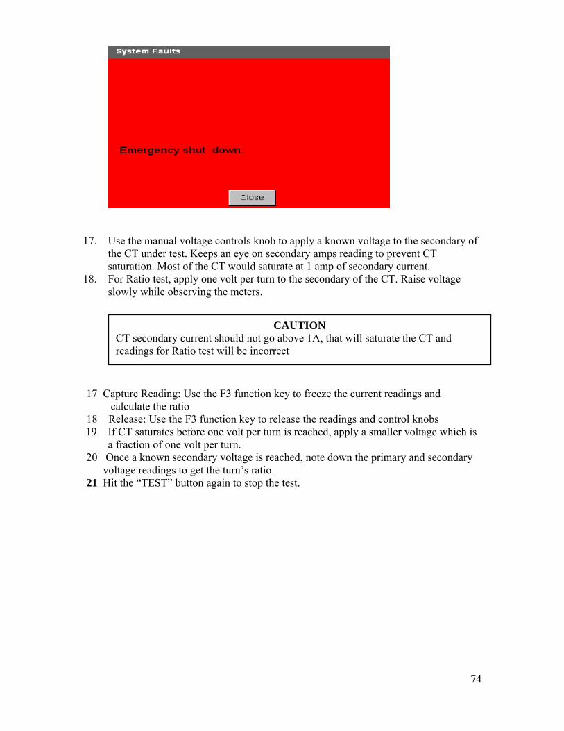
17. Use the manual voltage controls knob to apply a known voltage to the secondary of
the CT under test. Keeps an eye on secondary amps reading to prevent CT saturation. Most of the CT would saturate at 1 amp of secondary current.
18. For Ratio test, apply one volt per turn to the secondary of the CT. Raise voltage slowly while observing the meters.
CAUTION CT secondary current should not go above 1A, that will saturate the CT and readings for Ratio test will be incorrect
17 Capture Reading: Use the F3 function key to freeze the current readings and calculate the ratio 18 Release: Use the F3 function key to release the readings and control knobs
19 If CT saturates before one volt per turn is reached, apply a smaller voltage which is a fraction of one volt per turn. 20 Once a known secondary voltage is reached, note down the primary and secondary
voltage readings to get the turn’s ratio. 21 Hit the “TEST” button again to stop the test.

75
Burden Test: Burden test is performed to verify that CT under test is capable of supplying a known current into a know burden while maintaining its stated accuracy. A burden test is typically performed at full rated secondary current value. Burdens are typically expressed in VA.
Connections for the test: 1. Refer to the safety instructions first before use of the equipment. 2. Verify the Power ON/OFF switch is OFF. Power the test set from a suitable source
of power (95-265 V50/60 Hz). 3. Connect the ground wing nut to a suitable ground.
WARNING There is always the possibility of voltages being induced at the terminals of a test specimen because of proximity to high voltage energized lines. A residual static voltage charge may also be present at these terminals. Ground each terminal to be tested with a safety ground stick, before making connections.
4. Disconnect the burden on de-energized CT. Note: Refer to the Burden Test diagram (Figure7 & 8) in Appendix for more details.
5. Connect the test set secondary output binding posts X1 X2(Only), to the burden of the CT.
WARNING
The MCT produces high voltages and currents during the performance of tests. DO NOT TOUCH connector clips or test leads while the MCT is performing a test.
6. Turn Power ON/OFF switch to ON. 7. After the boot up, select the “Burden Test” menu from the main screen by using
scroll button. 8. In the burden test screen, hit F1 function button to select appropriate test amps
either 1 Amp or 5 Amp based upon secondary current rating of the CT under test.
9. Hit the “TEST” button to start the test.

76
10. A dialog box appears for confirmation of the test. Hit TEST button again.
WARNING High Voltage is now present at the terminals of the specimen and in the test leads
11. This will start the test and a warning high voltage symbol will appear on the “test in progress” screen.
12. At any point of time Test can be terminated by hitting the Test button again. Following message will appear.
13. Test can also be stopped under emergency condition by hitting the “Emergency
Push to Stop” button on the front panel of MCT 1600. Unit will shut off the output voltage and following message will appear.

77
14. After completion of test, Burden in VA and power factor results will be displayed
on the screen along with test voltages and current.
15. The measured burden should be less than or equal to the Burden (VA) rating of the
CT under test. 16. Save the results by hitting F5 function button.

78
Recalling and Saving of Results: Saving Results
1. After performing saturation, ratio, polarity, or insulation test hit F5 function key to
store the test results.
2. Enter the CT id to store the results. Test results are saved with CT id name.
Recalling Results
3. To recall a previous test result, select the “File Manager” option from the main
menu screen.
4. File manager screen will display all the test results stored into the internal memory of the unit.
5. Select the desired test and hit on F1 function key to load the test results. Following message will appear.

79
6. Screen will go to main menu from where different test results can be viewed.
Deleting Results 7. Hit F2 function key to delete any previously stored test results.
A confirmation box will come up; hit YES to delete a selected test.
Renaming File
8. Hit F3 function key to rename already stored file. Enter the new name in the dialog box and hit F1 function key to rename the file.
Transferring Results 9. Hit F4 function key to transfer the data from internal memory to USB stick. Either
of the two USB ports could be used for data transfer to USB stick.
Note: MCT1605 works on VX operating system. The recommended limit of USB
drive capacity is up to 1 GB. Home Screen 10. Hit F6 function key to return to main menu screen.

80
Appendix
Figure 6 Saturation, Ratio, and Polarity Test
Figure 7 Multi Ratio Current Transformer Test- A

81
Figure 8 Multi Ratio Current Transformer Test- B
• CT’s with no access to the primary side can be tested with connections to the secondary winding as shown above for multi-ratio CT’s.
• Voltage applied to the X1-X2 taps of the CT will induce a proportionate voltage on the remaining taps. By measuring voltage at different taps of CT, CT ratio can be verified.

82
Bushing CT’s can be tested in a de-energized circuit breaker which has been totally isolated from the power system. The breaker must be closed to perform ratio and polarity tests.
NOTE: The breaker does not have to be closed to perform the voltage test.
Figure 9 Testing Bushing CT installed in a Circuit Breaker

83
Bushing CT’s can be tested in a de-energized circuit breaker which has been totally isolated from the power system. CT secondary leads will normally terminate in the control cabinet. Refer to the chart on for connections.
Figure 10 Testing bushing CT installed in a Power Transformer- A
CT Locations
Tests Set Connections X1 X2 H1 H2
Jumpers
H1 Bushing
Secondary of H1 CT located in control cabinet
H1 Bushing
H2 Bushing
H2 - H3 X1 - X2 - X3
H2 Bushing
Secondary of H2 CT located in control cabinet
H2 Bushing
H3 Bushing
H3 - H1 X1 - X2 - X3
H3 Bushing
Secondary of H3 CT located in control cabinet
H3 Bushing
H1 Bushing
H1 - H2 X1 - X2 - X3

84
Bushing CT’s can be tested in a de-energized circuit breaker which has been totally isolated from the power system. CT secondary leads will normally terminate in the control cabinet. Refer to the chart on for connections.
Figure 11 Testing bushing CT installed in a Power Transformer- B
CT Locations
Tests Set Connections X1 X2 H1 H2
Jumpers
X1 Bushing
Secondary of X1 CT located in control cabinet
X1 Bushing
Neutral Bushing
H1 - H2 - H3
X2 Bushing
Secondary of X2 CT located in control cabinet
X2 Bushing
Neutral Bushing
H1 - H2 - H3
X3 Bushing
Secondary of X3 CT located in control cabinet
X3 Bushing
Neutral Bushing
H1 - H2 - H3

85
Insulation Testing
Figure 12 Three terminal insulation test specimen: Primary, Secondary and Ground
Figure 13 Primary to secondary Insulation measurement
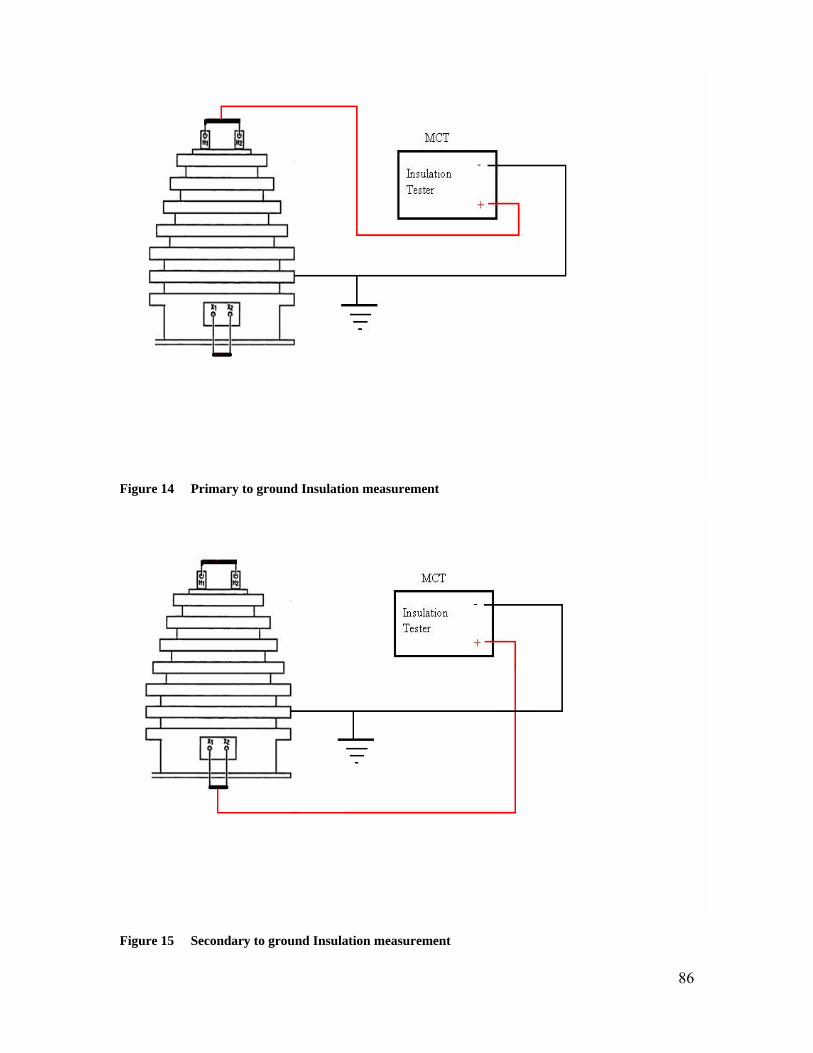
86
Figure 14 Primary to ground Insulation measurement
Figure 15 Secondary to ground Insulation measurement
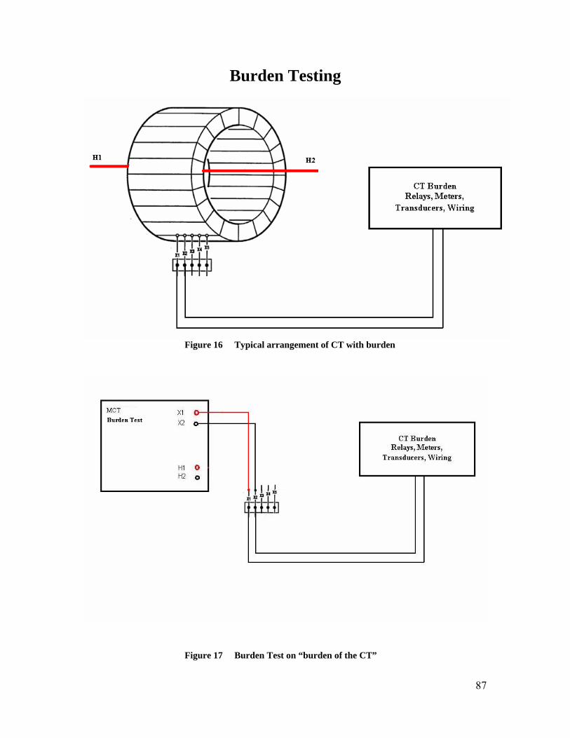
87
Burden Testing
Figure 16 Typical arrangement of CT with burden
Figure 17 Burden Test on “burden of the CT”

88
Power DB Lite Introduction PowerDB Lite provides you with professional looking data forms with minimal effort. Print your files to paper or .PDF and reduce the time it takes to complete your report generation. PowerDB Lite allows you to view the MCT test files and save the forms with test results onto your computer. Minimum Recommended System Operating System: Windows 2000 or later RAM: 64 MB RAM minimum, 512+ MB RAM recommended Processor: 300 MHz Pentium class processor minimum, 1 GHz or better recommended Software Installation To install PowerDB Lite: 1. Load the PowerDB Lite CD into your CD-Rom drive and follow the on-screen
instructions. 2. Double click on the PowerDB Lite exe file. Following messages will appear.
Hit OK.

89
3. Accept the terms of the license agreement by clicking ‘YES’.
4. Choose the destination location for the PowerDB Lite files.
Click Next.

90
5. Select default settings.
6. Install Shield Wizard will complete the installation of PowerDB Lite software. Click finish to close the installation program.
Viewing Test Results: Using PowerDB Lite
1. Open your Power DB Lite software. 2. Select your instrument from the Instrument Setup screen.

91
3. Click on File> Open to view the MCT test results.
4. Select the desired test file and hit Open. 5. Current Transformer Test file with date and time stamping will show up.
6. Select the file and hit Open to view the test results. To open a blank CT Test
Form, Hit ‘New’. 7. A Current transformer Test form will be opened displaying the test results.
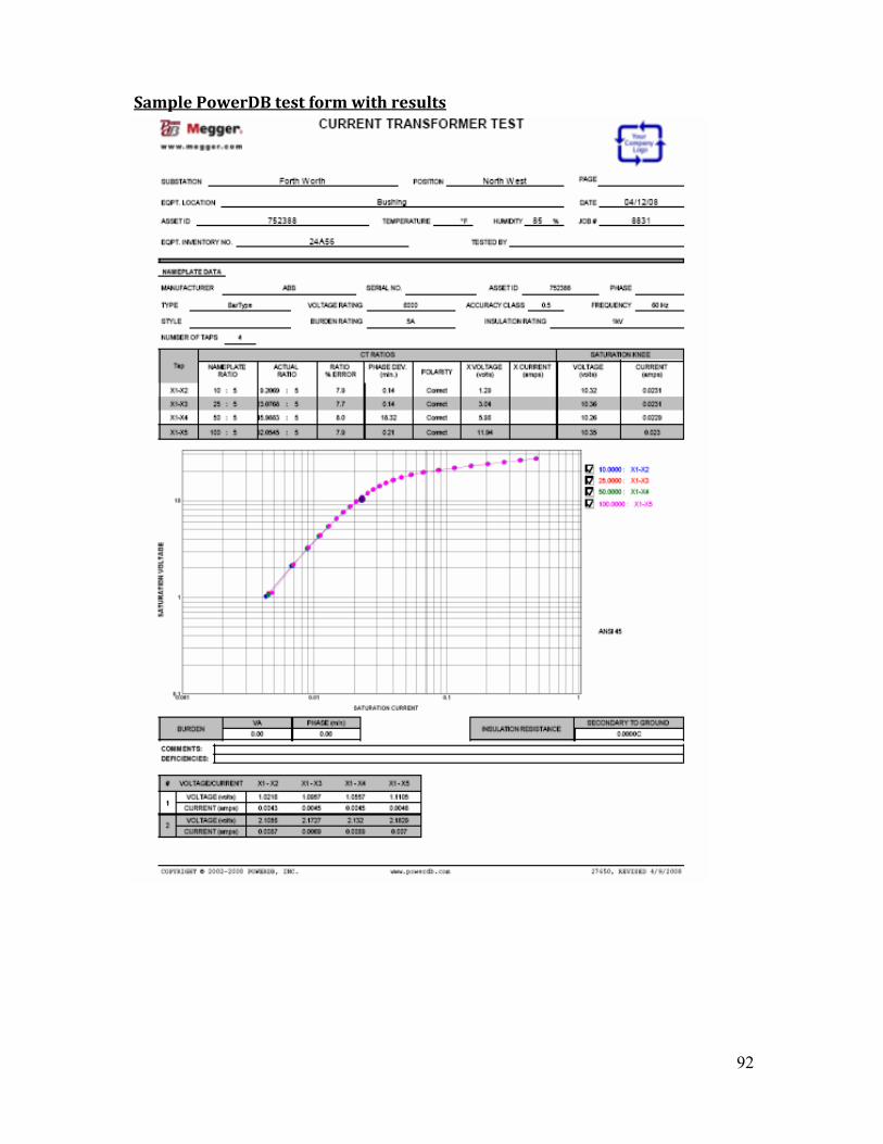
Sample PowerDB test form with results
92
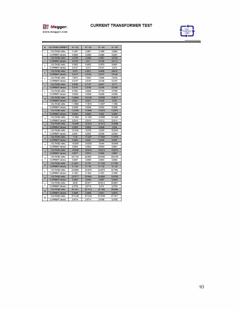
93

94
Specifications Input 95 to 265 V, 1ϕ, 50 or 60 Hz Output Continuously variable in six ranges: 0 to 40V at 5.0A max (15 minute on’ 15 minute off) 0 to 160 V at 5.0 A max (15 minute on’15 minute off) 0 to 800 V at 1.5 A max (5 min on, 15 min off)\ 0 to 1600 V at 1.0 A max (5 min on, 15 min off) Instrumentation Voltmeters Output 4 ½ digit, auto ranging Resolution: 0.0000 to 1.9999/19.999/199.99/1999.9 Ranges: 0 to 40/160/800/1600 Accuracy: +/- 0.5 % of reading and +/- 0.5% of range typical +- 1% of reading and +- 1 V maximum
Input 4 ½ digit, auto ranging Resolution: 0.0000 to 1.9999/19.999/199.99/600 V Ranges: 0 to 2/600V Accuracy: 2 V Range: +/- 0.5 % of reading and +/- 0.5% of range 600 V Range: +- 0.5% of reading and +-0.5% of range
Ammeter 4 ½ digit Range: 0.0000 to 1.0000A/10.000 Accuracy: +/- 0.85 % of reading and +/- LSD
Phase Angle 3 digits Range 0 to 360 degrees Accuracy: +/- 1 degree Ratio Range Accuracy 0.8 to 5000: +- 0.4% typical +-0.8% maximum

95
Insulation Test Test Voltage 1000 VDC, 500 VDC Measuring Range 10 KΩ – 999 MΩ Short circuit current 1.5 mA nominal Test current on load 1 mA at min. pass values of insulation (As specified in BS7671, HD 384 and IEC 364) Accuracy: +/- 3%, +/- 2 digits up to 10M +/- 5%, up to 100 M +/- 30% up to full scale Computer Interface USB Ethernet Environment Operating: -10ºC to 50ºC Storage: -30ºC to 70ºC Enclosure The unit is housed in a rugged enclosure suitable for use in outdoor substations Standards IEC 61010 CSA 22.2 CE Dimensions 7.5”H X 19.25” W X 15” D (190H X 489W X 940 D mm) Weight 47.6 lb (21.6 kg)

96
CT Demagnetization A magnetized CT with residual magnetism will give incorrect ratio and saturation results. It is very important to demagnetize the CT before/after every saturation test. MCT1605 automatically demagnetize the CT at the completion of the test. CT can have some residual magnetism if a large DC current was passed through it’s winding or high over currents were interrupted at it’s peak value. The effect of residual magnetism is when the CT is energized next time; it would result in CT ratio error and unpredictable early saturation. The MCT1605 demagnetizes the CT by applying a suitable AC voltage to CT secondary and taking it above saturation point. The unit then slowly decreases the secondary voltage back to zero thereby demagnetizing it and clearing any residual magnetism. The demagnetizing function is inbuilt to the unit and operator doesn’t have to do anything for CT demagnetization.
Maintenance & Calibration Maintenance Maintenance should be performed only by qualified persons familiar with the hazards involved with high voltage test equipment. Read and understand the safety section, before performing any service. Routine maintenance is all that is required for these test sets. The cables and connectors should be inspected frequently to be sure that all connections are tight and no damaged or loose connection has developed. The appearance of the test set can be maintained by occasional cleaning of the MCT case and assemblies. The front panel can be cleaned with a dry cloth or a cloth dampened with detergent and water. Do not allow water to penetrate through output terminals or any panel holes, because damage to components on the underside may result. Calibration A self calibration check can be done to verify the calibration of the unit. If there is any deviation in results from normal, please contact Megger for more information. A complete operation and calibration check is recommended at least once a year. Self Check:
1. Make sure test set is OFF 2. Connect the ground wing nut to a suitable ground. 3. Connect the H1 lead to X1 and H2 lead to X2. 4. Turn the test set ON. 5. From main screen, select the manual option. 6. Select the Voltage range as 40V by using F2 function button. 7. Apply a certain test voltage, for example 10V to the secondary X1 and X2. 8. Read the primary and secondary voltage readings from the screen. 9. Observe that both the readings should be same, or very close to each other. 10. Now increase the voltage to 20 V gradually. The change in secondary voltage will
reflect same and proportionate change in primary voltage.

97
Warranty & Repair Warranty Megger warrants to the original purchaser that the product is free from defects in material and workmanship for a period of one (1) year from the date of shipment. This warranty is limited and shall not apply to equipment which has damage, or cause of defect, due to accident, negligence, and improper operation, faulty installation by purchaser, or improper service or repair by any person, company or corporation not authorized by Megger. If examination by Megger discloses that the product is or has been defective, then our obligation is limited to repair or replacement of the defective units or its components, at our option. The foregoing warranty constitutes Megger’s sole liability and is in lieu of any other warranty of merchantability or fitness. Megger shall not be responsible for any incidental or consequential damages arising from any breach of warranty. Repair In the event that MCT1605 appears defective, call the Megger Dallas service department at 1-800-723 2861.The service and technical support department will determine the cause of apparent malfunction and provide the necessary support to correct the problem. At times, problems can be corrected by troubleshooting on phone. Therefore, before returning the equipment to the factory for repair/service discuss all problems with Megger. If factory service is required, request repair service department for return instructions. A Return Authorization (RA) number will be assigned for proper handling of the unit when it arrives at the factory. Provide relevant information like model number, serial number of the unit, nature of the problem, return address, your name and where you can be reached should the factory need to contact you.