md10c users manual
DESCRIPTION
CYTRONTRANSCRIPT
MD10C
Enhanced 10A DC Motor Driver
User’s Manual
V1.0
May 2012
Information contained in this publication regarding device applications and the like is intended through suggestion only and
may be superseded by updates. It is your responsibility to ensure that your application meets with your specifications. No
representation or warranty is given and no liability is assumed by Cytron Technologies Incorporated with respect to the
accuracy or use of such information or infringement of patents or other intellectual property rights arising from such use or
otherwise. Use of Cytron Technologies’s products as critical components in life support systems is not authorized except
with express written approval by Cytron Technologies. No licenses are conveyed, implicitly or otherwise, under any
intellectual property rights.
ROBOT . HEAD to TOE Product User’s Manual – MD10C
Index
1. Introduction and Overview 3
2. Packing List 4
3. Product Specification and Limitations 5
4. Dimension 6
5. Board Layout 7
6. Installation and Getting Started 9
6.1 Selecting board supply 9
6.2 Getting Started MD10C with SK40C 10
7. Warranty 12
Created by Cytron Technologies Sdn. Bhd. – All Rights Reserved
ROBOT . HEAD to TOE Product User’s Manual – MD10C
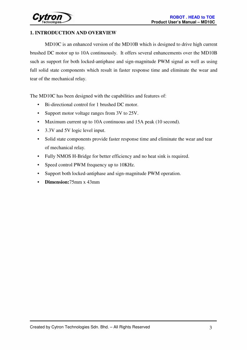
1. INTRODUCTION AND OVERVIEW
MD10C is an enhanced version of the MD10B which is designed to drive high current
brushed DC motor up to 10A continuously. It offers several enhancements over the MD10B
such as support for both locked-antiphase and sign-magnitude PWM signal as well as using
full solid state components which result in faster response time and eliminate the wear and
tear of the mechanical relay.
The MD10C has been designed with the capabilities and features of:
• Bi-directional control for 1 brushed DC motor.
• Support motor voltage ranges from 3V to 25V.
• Maximum current up to 10A continuous and 15A peak (10 second).
• 3.3V and 5V logic level input.
• Solid state components provide faster response time and eliminate the wear and tear
of mechanical relay.
• Fully NMOS H-Bridge for better efficiency and no heat sink is required.
• Speed control PWM frequency up to 10KHz.
• Support both locked-antiphase and sign-magnitude PWM operation.
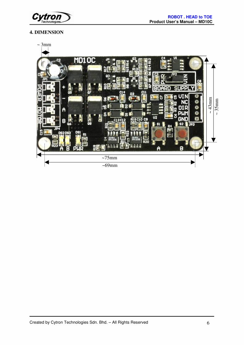
• Dimension:75mm x 43mm
Created by Cytron Technologies Sdn. Bhd. – All Rights Reserved 3
ROBOT . HEAD to TOE Product User’s Manual – MD10C
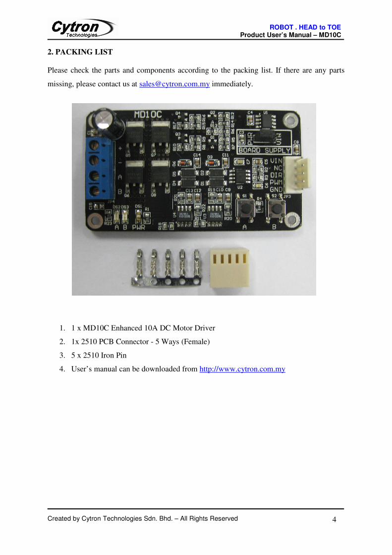
2. PACKING LIST
Please check the parts and components according to the packing list. If there are any parts
missing, please contact us at [email protected] immediately.
1. 1 x MD10C Enhanced 10A DC Motor Driver
2. 1x 2510 PCB Connector - 5 Ways (Female)
3. 5 x 2510 Iron Pin
4. User’s manual can be downloaded from http://www.cytron.com.my
Created by Cytron Technologies Sdn. Bhd. – All Rights Reserved 4

ROBOT . HEAD to TOE Product User’s Manual – MD10C
3. PRODUCT SPECIFICATION AND LIMITATIONS
Absolute Maximum Rating
No Parameters Min Typical Max Unit
1 Power Input Voltage (Motor Supply Voltage) 3 - 25 V
2 IMAX (Maximum Continuous Motor Current) - - 10 A
3 IPEAK – (Peak Motor Current) * - - 15 A
4 VIN (Board Supply Voltage) 11 12 14 V
5 VIOH (Logic Input – High Level) 3 - 5.5 V
6 VIOL (Logic Input – Low Level) 0 0 0.5 V
7 Maximum PWM Frequency - - 10 KHz
* Must not exceed 10 seconds.
Created by Cytron Technologies Sdn. Bhd. – All Rights Reserved 5
ROBOT . HEAD to TOE Product User’s Manual – MD10C
4. DIMENSION
Created by Cytron Technologies Sdn. Bhd. – All Rights Reserved 6
~75mm
~ 4
3m
m
~ 3mm
~69mm
~ 3
5m
m
ROBOT . HEAD to TOE Product User’s Manual – MD10C
5. BOARD LAYOUT
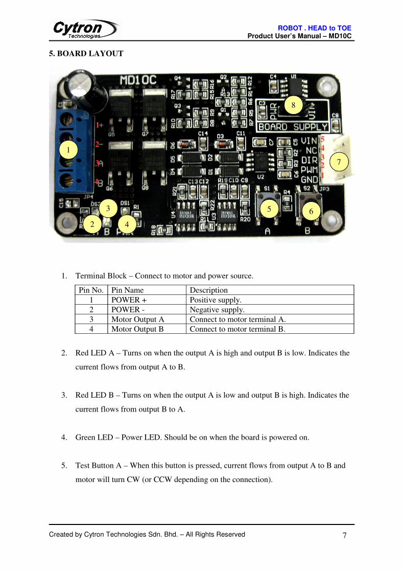
1. Terminal Block – Connect to motor and power source.
Pin No. Pin Name Description
1 POWER + Positive supply.
2 POWER - Negative supply.
3 Motor Output A Connect to motor terminal A.
4 Motor Output B Connect to motor terminal B.
2. Red LED A – Turns on when the output A is high and output B is low. Indicates the
current flows from output A to B.
3. Red LED B – Turns on when the output A is low and output B is high. Indicates the
current flows from output B to A.
4. Green LED – Power LED. Should be on when the board is powered on.
5. Test Button A – When this button is pressed, current flows from output A to B and
motor will turn CW (or CCW depending on the connection).
Created by Cytron Technologies Sdn. Bhd. – All Rights Reserved 7
1
6
7
8
2
53
4
1
4
2
3
1
23
45
ROBOT . HEAD to TOE Product User’s Manual – MD10C
6. Test Button B – When this button is pressed, current flows from output B to A and
motor will turn CCW (or CW depending on the connection).
7. Input
Pin No. Pin Name Description
1 GND Logic ground.
2 PWM PWM input for speed control.
3 DIR Direction control.
4 NC Not connected. This pin is not used.
5 VIN* Board power supply.
* This can be left unconnected if the board is powered by motor power input.
The truth table for the control logic is as follow:
Pin 2 (PWM) Pin 3 (DIR) Output A Output B
Low X (Don’t Care) Low Low
High Low High Low
High High Low High
8. Jumper – Board Supply Selector
PWR: Board is powered by motor power input. Only select this when the motor
power input is > 14V.
VIN: Board is powered by VIN. 12V must be supplied to the VIN pin and motor
power input can be 3V – 25V.
Created by Cytron Technologies Sdn. Bhd. – All Rights Reserved 8
ROBOT . HEAD to TOE Product User’s Manual – MD10C
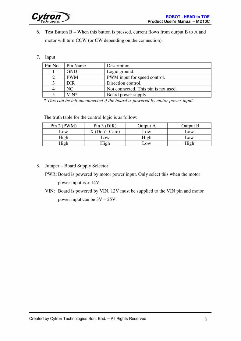
6. INSTALLATION AND GETTING STARTED
6.1 Selecting Board Supply
Before using the MD10C, user needs to determine the power source for the board by using
the onboard jumper. By default, VIN is selected as the board supply and this can be used in
all cases. In this mode, 12V must be supplied to the VIN pin at the input port.
VIN is selected as board power supply
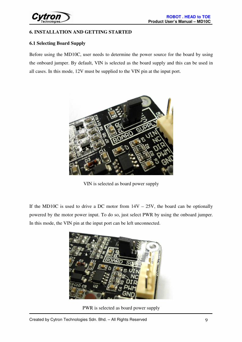
If the MD10C is used to drive a DC motor from 14V – 25V, the board can be optionally
powered by the motor power input. To do so, just select PWR by using the onboard jumper.
In this mode, the VIN pin at the input port can be left unconnected.
PWR is selected as board power supply
Created by Cytron Technologies Sdn. Bhd. – All Rights Reserved 9
ROBOT . HEAD to TOE Product User’s Manual – MD10C
6.2 Getting Started MD10C with SK40C
MD10C is compatible with 2 types of PWM operation, which are:
1. Sign-Magnitude PWM – For sign-magnitude PWM operation, 2 control signals are used
to control the speed and direction of the motor. PWM is feed to the PWM pin to control
the speed while DIR pin is used to control the direction of the motor.
2. Locked-Antiphase PWM – For locked-antiphase PWM operation, only 1 control signal is
needed to control the speed and direction of the motor. PWM pin is connected to logic
high while the DIR pin is being feed with the PWM signal. When the PWM signal has
50% duty cycle, the motor stops running. If the PWM has less than 50% duty cycle, the
motor will turn CW (or CCW depending on the connection). If the PWM signal has more
than 50% duty cycle, motor will turn CCW (or CW depending on the connection).
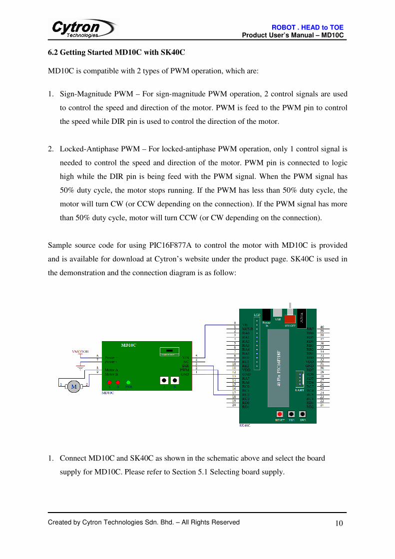
Sample source code for using PIC16F877A to control the motor with MD10C is provided
and is available for download at Cytron’s website under the product page. SK40C is used in
the demonstration and the connection diagram is as follow:
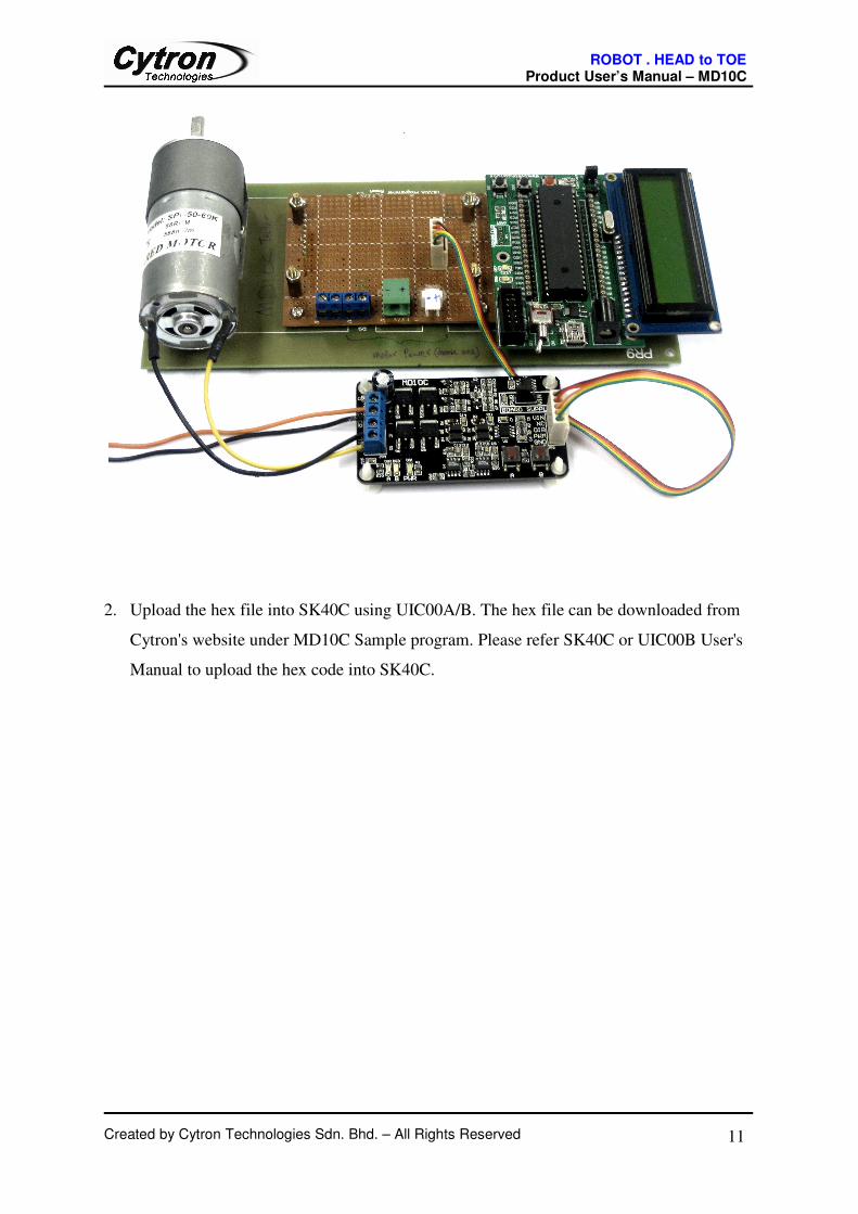
1. Connect MD10C and SK40C as shown in the schematic above and select the board
supply for MD10C. Please refer to Section 5.1 Selecting board supply.
Created by Cytron Technologies Sdn. Bhd. – All Rights Reserved 10
ROBOT . HEAD to TOE Product User’s Manual – MD10C
2. Upload the hex file into SK40C using UIC00A/B. The hex file can be downloaded from
Cytron's website under MD10C Sample program. Please refer SK40C or UIC00B User's
Manual to upload the hex code into SK40C.
Created by Cytron Technologies Sdn. Bhd. – All Rights Reserved 11
ROBOT . HEAD to TOE Product User’s Manual – MD10C
7. WARRANTY
� Product warranty is valid for 6 months.
� Warranty only applies to manufacturing defect.
� Damage caused by mis-use is not covered under warranty.
� Warranty does not cover freight cost for both ways.
Created by Cytron Technologies Sdn. Bhd. – All Rights Reserved 12
Prepared by
Cytron Technologies Sdn. Bhd.
19, Jalan Kebudayaan 1A,
Taman Universiti,
81300 Skudai,
Johor, Malaysia.
Tel: +607-521 3178
Fax: +607-521 1861
URL: www.cytron.com.my
Email: [email protected]