mds-c1-n series specifications and instruction manual
TRANSCRIPT


Introduction
Thank you for selecting the Mitsubishi numerical control unit. This instruction manual describes the handling and
caution points for using this AC servo/spindle.Incorrect handling may lead to unforeseen accidents, so always read
this instruction manual thoroughly to ensure correct usage.
Make sure that this instruction manual is delivered to the end user. Always store this manual in a safe place.
In order to confirm if all function specifications described in this manual are applicable, refer to the specifications for
each CNC.
Notes on Reading This Manual
(1) Since the description of this specification manual deals with NC in general, for the specifications of individual
machine tools, refer to the manuals issued by the respective machine tool builders. The "restrictions" and
"available functions" described in the manuals issued by the machine tool builders have precedence to those
in this manual.
(2) This manual describes as many special operations as possible, but it should be kept in mind that items not
mentioned in this manual cannot be performed.
In this manual, the following abbreviations might be used.
MTB: Machine tool builder


Precautions for Safety
Please read this manual and auxiliary documents before starting installation, operation, maintenance or inspection
to ensure correct usage. Thoroughly understand the device, safety information and precautions before starting
operation.
The safety precautions in this instruction manual are ranked as "WARNING" and "CAUTION".
Note that some items described as " CAUTION" may lead to major results depending on the situation. In any
case, important information that must be observed is described.
DANGER
When there is a potential risk of fatal or serious injuries if handling is mistaken.
WARNING
When a dangerous situation, or fatal or serious injuries may occur if handling is mistaken.
CAUTION
When a dangerous situation may occur if handling is mistaken leading to medium or minor injuries, or physical
damage.
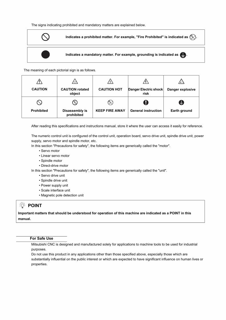
The signs indicating prohibited and mandatory matters are explained below.
The meaning of each pictorial sign is as follows.
After reading this specifications and instructions manual, store it where the user can access it easily for reference.
The numeric control unit is configured of the control unit, operation board, servo drive unit, spindle drive unit, power
supply, servo motor and spindle motor, etc.
In this section "Precautions for safety", the following items are generically called the "motor".
• Servo motor
• Linear servo motor
• Spindle motor
• Direct-drive motor
In this section "Precautions for safety", the following items are generically called the "unit".
• Servo drive unit
• Spindle drive unit
• Power supply unit
• Scale interface unit
• Magnetic pole detection unit
Mitsubishi CNC is designed and manufactured solely for applications to machine tools to be used for industrial
purposes.
Do not use this product in any applications other than those specified above, especially those which are
substantially influential on the public interest or which are expected to have significant influence on human lives or
properties.
Indicates a prohibited matter. For example, "Fire Prohibited" is indicated as .
Indicates a mandatory matter. For example, grounding is indicated as .
CAUTION
CAUTION rotated
object
CAUTION HOT
Danger Electric shock
risk
Danger explosive
Prohibited
Disassembly is
prohibited
KEEP FIRE AWAY
General instruction
Earth ground
POINT
Important matters that should be understood for operation of this machine are indicated as a POINT in this
manual.
For Safe Use

1. Electric shock prevention
Do not open the front cover while the power is ON or during operation. Failure to observe this could lead to
electric shocks.
Do not operate the unit with the front cover removed. The high voltage terminals and charged sections will
be exposed, and can cause electric shocks.
Do not remove the front cover and connector even when the power is OFF unless carrying out wiring work
or periodic inspections. The inside of the units is charged, and can cause electric shocks.
Since the high voltage is supplied to the main circuit connector while the power is ON or during operation,
do not touch the main circuit connector with an adjustment screwdriver or the pen tip. Failure to observe
this could lead to electric shocks.
Wait at least 15 minutes after turning the power OFF, confirm that the CHARGE lamp has gone out, and
check the voltage between P and N terminals with a tester, etc., before starting wiring, maintenance or
inspections. Failure to observe this could lead to electric shocks.
Ground the unit and motor. For the motor, ground it via the drive unit.
Wiring, maintenance and inspection work must be done by a qualified technician.
Wire the servo drive unit and servo motor after installation. Failure to observe this could lead to electric
shocks.
Do not touch the switches with wet hands. Failure to observe this could lead to electric shocks.
Do not damage, apply forcible stress, place heavy items on the cables or get them caught. Failure to
observe this could lead to electric shocks.
Always insulate the power terminal connection section. Failure to observe this could lead to electric
shocks.
After assembling the built-in IPM spindle motor, if the rotor is rotated by hand etc., voltage occurs between
the terminals of lead. Take care not to get electric shocks.
WARNING

2. Injury prevention
When handling a motor, perform operations in safe clothing.
In the system where the optical communication with CNC is executed, do not see directly the light
generated from CN1A/CN1B connector of drive unit or the end of cable. When the light gets into eye, you
may feel something is wrong for eye.
(The light source of optical communication corresponds to class1 defined in JISC6802 or IEC60825-1.)
The linear servo motor, direct-drive motor and built-in IPM spindle motor uses permanent magnets in the
rotor, so observe the following precautions.
(1)Handling
• The linear servo motor, direct-drive motor and built-in IPM spindle motor could adversely affect medical
electronics such as pacemakers, etc., therefore, do not approach the rotor.
• Do not place magnetic materials as iron.
• When a magnetic material as iron is placed, take safety measure not to pinch fingers or hands due to the
magnetic attraction force.
• Remove metal items such as watch, piercing jewelry, necklace, etc.
• Do not place portable items that could malfunction or fail due to the influence of the magnetic force.
• When the rotor is not securely fixed to the machine or device, do not leave it unattended but store it in the
package properly.
• When installing the motor to the machine, take it out from the package one by one, and then install it.
• It is highly dangerous to lay out the motor or magnetic plates together on the table or pallet, therefore never
do so.
(2)Transportation and storage
• Correctly store the rotor in the package to transport and store.
• During transportation and storage, draw people's attention by applying a notice saying "Strong magnet-
Handle with care" to the package or storage shelf.
• Do not use a damaged package.
(3)Installation
• Take special care not to pinch fingers, etc., when installing (and unpacking) the linear servo motor.
WARNING

1. Fire prevention
Install the units, motors and regenerative resistor on non-combustible material. Direct installation on
combustible material or near combustible materials could lead to fires.
Always install a circuit protector and contactor on the servo drive unit power input as explained in this
manual. Refer to this manual and select the correct circuit protector and contactor. An incorrect selection
could result in fire.
Shut off the power on the unit side if a fault occurs in the units. Fires could be caused if a large current
continues to flow.
When using a regenerative resistor, provide a sequence that shuts off the power with the regenerative
resistor's error signal. The regenerative resistor could abnormally overheat and cause a fire due to a fault
in the regenerative transistor, etc.
The battery unit could heat up, ignite or rupture if submerged in water, or if the poles are incorrectly wired.
Cut off the main circuit power with the contactor when an alarm or emergency stop occurs.
2. Injury prevention
Do not apply a voltage other than that specified in this manual, on each terminal. Failure to observe this
item could lead to ruptures or damage, etc.
Do not mistake the terminal connections. Failure to observe this item could lead to ruptures or damage,
etc.
Do not mistake the polarity (+,- ). Failure to observe this item could lead to ruptures or damage, etc.
Do not touch the radiation fin on unit back face, regenerative resistor or motor, etc., or place parts (cables,
etc.) while the power is turned ON or immediately after turning the power OFF. These parts may reach high
temperatures, and can cause burns or part damage.
Structure the cooling fan on the unit back face, etc., etc so that it cannot be touched after installation.
Touching the cooling fan during operation could lead to injuries.
Take care not to suck hair, clothes, etc. into the cooling fan.
CAUTION

3. Various precautions
Observe the following precautions. Incorrect handling of the unit could lead to faults, injuries and electric shocks, etc.
(1) Transportation and installation
Correctly transport the product according to its weight.
Use the motor's hanging bolts only when transporting the motor. Do not transport the machine when the
motor is installed on the machine.
Do not stack the products above the tolerable number.
Follow this manual and install the unit or motor in a place where the weight can be borne.
Do not get on top of or place heavy objects on the unit.
Do not hold the cables, axis or encoder when transporting the motor.
Do not hold the connected wires or cables when transporting the units.
Do not hold the front cover when transporting the unit. The unit could drop.
Always observe the installation directions of the units or motors.
Secure the specified distance between the units and control panel, or between the servo drive unit and
other devices.
Do not install or run a unit or motor that is damaged or missing parts.
Do not block the intake or exhaust ports of the motor provided with a cooling fan.
Do not let foreign objects enter the units or motors. In particular, if conductive objects such as screws or
metal chips, etc., or combustible materials such as oil enter, rupture or breakage could occur.
Provide adequate protection using a material such as connector for conduit to prevent screws, metallic
detritus, water and other conductive matter or oil and other combustible matter from entering the motor
through the power line lead-out port.
The units, motors and encoders are precision devices, so do not drop them or apply strong impacts to
them.
CAUTION

Store and use the units under the following environment conditions.
(Note 1) For details, confirm each unit or motor specifications in addition.
(Note 2) -15°C to +55°C for linear servo motor.
When disinfectants or insecticides must be used to treat wood packaging materials, always use methods
other than fumigation (for example, apply heat treatment at the minimum wood core temperature of 56 °C
for a minimum duration of 30 minutes (ISPM No. 15 (2009))).
If products such as units are directly fumigated or packed with fumigated wooden materials, halogen
substances (including fluorine, chlorine, bromine and iodine) contained in fumes may contribute to the
erosion of the capacitors.
When exporting the products, make sure to comply with the laws and regulations of each country.
Do not use the products in conjunction with any components that contain halogenated flame retardants
(bromine, etc). Failure to observe this may cause the erosion of the capacitors.
Securely fix the servo motor to the machine. Insufficient fixing could lead to the servo motor slipping off
during operation.
Always install the servo motor with reduction gear in the designated direction. Failure to do so could lead
to oil leaks.
Structure the rotary sections of the motor so that it can never be touched during operation. Install a cover,
etc., on the shaft.
When installing a coupling to a servo motor shaft end, do not apply an impact by hammering, etc. The
encoder could be damaged.
Do not apply a load exceeding the tolerable load onto the servo motor shaft. The shaft could break.
Store the motor in the package box.
When inserting the shaft into the built-in IPM spindle motor, do not heat the rotor higher than 130°C. The
magnet could be demagnetized, and the specifications characteristics will not be ensured.
Always use a nonmagnetic tool (explosion-proof beryllium copper alloy safety tool: NGK Insulators, etc.)
when installing the built-in IPM spindle motor, direct-drive motor and linear servo motor.
Always provide a mechanical stopper on the end of the linear servo motor's travel path.
If the unit has been stored for a long time, always check the operation before starting actual operation.
Please contact the Service Center, Service Station, Sales Office or delayer.
Install the heavy peripheral devices to the lower part in the panel and securely fix it not to be moved due to
vibration.
CAUTION
Environment Unit Servo motor Spindle motor
Ambient temperature
Operation: 0 to +55°C (with no freezing),
Storage / Transportation: -15°C to +70°C(with no freezing)
Operation: 0 to +40°C (with no freezing),
Storage: -15°C to +70°C (Note 2) (with no freezing)
Operation: 0 to +40°C (with no freezing),
Storage: -20°C to +65°C(with no freezing)
Ambient humidity
Operation: 90%RH or less (with no dew condensation)
Storage / Transportation: 90%RH or less (with no dew condensation)
Operation: 80%RH or less (with no dew condensation),
Storage: 90%RH or less (with no dew condensation)
Operation: 90%RH or less (with no dew condensation)
Storage: 90%RH or less (with no dew condensation)
AtmosphereIndoors (no direct sunlight)
With no corrosive gas, inflammable gas, oil mist, dust or conductive fine particles
Altitude
Operation/Storage: 1000 meters or less above sea level,
Transportation: 13000 meters or less above sea level
Operation/Storage:1000 meters or less above sea level,
Transportation: 10000 meters or less above sea level
Vibration/impact According to each unit or motor specification

(2) Wiring
Correctly and securely perform the wiring. Failure to do so could lead to abnormal operation of the motor.
Do not install a condensing capacitor, surge absorber or radio noise filter on the output side of the drive
unit.
Correctly connect the output side of the drive unit (terminals U, V, W). Failure to do so could lead to
abnormal operation of the motor.
When using a power regenerative power supply unit, always install an AC reactor for each power supply
unit.
In the main circuit power supply side of the unit, always install an appropriate circuit protector or contactor
for each unit. Circuit protector or contactor cannot be shared by several units.
Always connect the motor to the drive unit's output terminals (U, V, W).
Do not directly connect a commercial power supply to the servo motor. Failure to observe this could result
in a fault.
When using an inductive load such as a relay, always connect a diode as a noise measure parallel to the
load.
When using a capacitance load such as a lamp, always connect a protective resistor as a noise measure
serial to the load.
Do not reverse the direction of a diode which
connect to a DC relay for the control output
signals such as contractor and motor brake
output, etc. to suppress a surge. Connecting it
backwards could cause the drive unit to
malfunction so that signals are not output, and
emergency stop and other safety circuits are inoperable.
Do not connect/disconnect the cables connected between the units while the power is ON.
Securely tighten the cable connector fixing screw or fixing mechanism. An insecure fixing could cause the
cable to fall off while the power is ON.
When using a shielded cable instructed in the instruction manual, always ground the cable with a cable
clamp, etc. (Refer to "EMC Installation Guidelines")
Always separate the signals wires from the drive wire and power line.
Use wires and cables that have a wire diameter, heat resistance and flexibility that conforms to the system.
(3) Trial operation and adjustment
Check and adjust each program and parameter before starting operation. Failure to do so could lead to
unforeseen operation of the machine.
Do not make remarkable adjustments and changes of parameter as the operation could become unstable.
The usable motor and unit combination is predetermined. Always check the combinations and parameters
before starting trial operation.
The direct-drive motor and linear servo motor do not have a stopping device such as magnetic brakes.
Install a stopping device on the machine side.
When using the linear servo motor for an unbalance axis, adjust the unbalance weight to 0 by installing an
air cylinder, etc. on the machine side. The unbalance weight disables the initial magnetic pole adjustment.
CAUTION
RA
COM(24VDC)
COM(24VDC)
RA
Servo drive unit Servo drive unit
Control outputsignal
Control outputsignal

(4) Usage methods
In abnormal state, install an external emergency stop circuit so that the operation can be stopped and
power shut off immediately.
Turn the power OFF immediately if smoke, abnormal noise or odors are generated from the unit or motor.
Do not disassemble or repair this product.
Never make modifications.
When an alarm occurs, the machine will start suddenly if an alarm reset (RST) is carried out while an
operation start signal (ST) is being input. Always confirm that the operation signal is OFF before carrying
out an alarm reset. Failure to do so could lead to accidents or injuries.
Reduce magnetic damage by installing a noise filter. The electronic devices used near the unit could be
affected by magnetic noise. Install a line noise filter, etc., if there is a risk of magnetic noise.
Use the unit, motor and regenerative resistor with the designated combination. Failure to do so could lead
to fires or trouble.
The brake (magnetic brake) of the servo motor are for holding, and must not be used for normal braking.
There may be cases when holding is not possible due to the magnetic brake's life, the machine
construction (when ball screw and servo motor are coupled via a timing belt, etc.) or the magnetic brake's
failure. Install a stop device to ensure safety on the machine side.
After changing the programs/parameters or after maintenance and inspection, always test the operation
before starting actual operation.
Do not enter the movable range of the machine during automatic operation. Never place body parts near or
touch the spindle during rotation.
Follow the power supply specification conditions given in each specification for the power (input voltage,
input frequency, tolerable sudden power failure time, etc.).
Set all bits to "0" if they are indicated as not used or empty in the explanation on the bits.
Do not use the dynamic brakes except during the emergency stop. Continued use of the dynamic brakes
could result in brake damage.
If a circuit protector for the main circuit power supply is shared by several units, the circuit protector may
not activate when a short-circuit fault occurs in a small capacity unit. This is dangerous, so never share the
circuit protector.
Mitsubishi spindle motor is dedicated to machine tools. Do not use for other purposes.
(5) Troubleshooting
If a hazardous situation is predicted during power failure or product trouble, use a servo motor with
magnetic brakes or install an external brake mechanism.
Use a double circuit configuration that allows the
operation circuit for the magnetic brakes to be operated
even by the external emergency stop signal.
Always turn the main circuit power of the motor OFF
when an alarm occurs.
If an alarm occurs, remove the cause, and secure the
safety before resetting the alarm.
CAUTION
MBREMG
Servo motor
Magneticbrake
Shut off with the servo motorbrake control output.
Shut off with NC brake control PLC output.
24VDC

(6) Maintenance, inspection and part replacement
Always backup the programs and parameters before starting maintenance or inspections.
The capacity of the electrolytic capacitor will drop over time due to self-discharging, etc. To prevent
secondary disasters due to failures, replacing this part every five years when used under a normal
environment is recommended. Contact the Service Center, Service Station, Sales Office or delayer for
repairs or part replacement.
Do not perform a megger test (insulation resistance measurement) during inspections.
If the battery low warning is issued, immediately replace the battery. Replace the batteries while applying
the drive unit's control power.
Do not short circuit, charge, overheat, incinerate or disassemble the battery.
For after-purchase servicing of the built-in motor, only the servicing parts for MITSUBISHI encoder can be
supplied. For the motor body, prepare the spare parts at the machine tool builders.
For maintenance, part replacement, and services in case of failures in the built-in motor (including the
encoder), take necessary actions at the machine tool builders. For drive unit, Mitsubishi can offer the after-
purchase servicing as with the general drive unit.
(7) Disposal
Take the batteries and backlights for LCD, etc., off from the controller, drive unit and motor, and dispose of
them as general industrial wastes.
Do not disassemble the unit or motor.
Dispose of the battery according to local laws.
Always return the secondary side (magnet side) of the linear servo motor to the Service Center or Service
Station.
When incinerating optical communication cable, hydrogen fluoride gas or hydrogen chloride gas which is
corrosive and harmful may be generated. For disposal of optical communication cable, request for
specialized industrial waste disposal services that has incineration facility for disposing hydrogen fluoride
gas or hydrogen chloride gas.
(8) Transportation
The unit and motor are precision parts and must be handled carefully.
According to a United Nations Advisory, the battery unit and battery must be transported according to the
rules set forth by the International Civil Aviation Organization (ICAO), International Air Transportation
Association (IATA), International Maritime Organization (IMO), and United States Department of
Transportation (DOT), etc.
(9) General precautions
The drawings given in this manual show the covers and safety partitions, etc., removed to provide a clearer
explanation. Always return the covers or partitions to their respective places before starting operation, and
always follow the instructions given in this manual.
CAUTION

Treatment of waste
The following two laws will apply when disposing of this product. Considerations must be made to each law.
The following laws are in effect in Japan. Thus, when using this product overseas, the local laws will have a
priority. If necessary, indicate or notify these laws to the final user of the product.
(1) Requirements for "Law for Promotion of Effective Utilization of Resources"
(a) Recycle as much of this product as possible when finished with use.
(b) When recycling, often parts are sorted into steel scraps and electric parts, etc., and sold to scrap
contractors. Mitsubishi recommends sorting the product and selling the members to appropriate
contractors.
(2) Requirements for "Law for Treatment of Waste and Cleaning"
(a) Mitsubishi recommends recycling and selling the product when no longer needed according to item
(1) above. The user should make an effort to reduce waste in this manner.
(b) When disposing a product that cannot be resold, it shall be treated as a waste product.
(c) The treatment of industrial waste must be commissioned to a licensed industrial waste treatment
contractor, and appropriate measures, including a manifest control, must be taken.
(d) Batteries correspond to "primary batteries", and must be disposed of according to local disposal
laws.


Disposal
(Note) This symbol mark is for EU countries only.
This symbol mark is according to the directive 2006/66/EC Article 20 Information for end-
users and Annex II.
Your MITSUBISHI ELECTRIC product is designed and manufactured with high quality materials and
components which can be recycled and/or reused.
This symbol means that batteries and accumulators, at their end-of-life, should be disposed of
separately from your household waste.
If a chemical symbol is printed beneath the symbol shown above, this chemical symbol means that the
battery or accumulator contains a heavy metal at a certain concentration. This will be indicated as
follows:
Hg: mercury (0,0005%), Cd: cadmium (0,002%), Pb: lead (0,004%)
In the European Union there are separate collection systems for used batteries and accumulators.
Please, dispose of batteries and accumulators correctly at your local community waste collection/
recycling centre.
Please, help us to conserve the environment we live in!


Trademarks
MELDAS, MELSEC, EZSocket, EZMotion, iQ Platform, MELSOFT, GOT, CC-Link, CC-Link/LT and CC-Link
IE are either trademarks or registered trademarks of Mitsubishi Electric Corporation in Japan and/or other
countries.
Other company and product names that appear in this manual are trademarks or registered trademarks of the
respective companies.


本製品の取扱いについて
( 日本語 /Japanese)
本製品は工業用 ( クラス A) 電磁環境適合機器です。販売者あるいは使用者はこの点に注意し、住商業環境以外で
の使用をお願いいたします。
Handling of our product
(English)
This is a class A product. In a domestic environment this product may cause radio interference in which case the
user may be required to take adequate measures.
본 제품의 취급에 대해서
( 한국어 /Korean)
이 기기는 업무용 (A 급 ) 전자파적합기기로서 판매자 또는 사용자는 이 점을 주의하시기 바라며 가정외의 지역에
서 사용하는 것을 목적으로 합니다 .


WARRANTY Please confirm the following product warranty details before using MITSUBISHI CNC. 1. Warranty Period and Coverage
Should any fault or defect (hereafter called "failure") for which we are liable occur in this product during the warranty period, we shall provide repair services at no cost through the distributor from which the product was purchased or through a Mitsubishi Electric service provider. Note, however that this shall not apply if the customer was informed prior to purchase of the product that the product is not covered under warranty. Also note that we are not responsible for any on-site readjustment and/or trial run that may be required after a defective unit is replaced.
[Warranty Term] The term of warranty for this product shall be twenty-four (24) months from the date of delivery of product to the end user, provided the product purchased from us in Japan is installed in Japan (but in no event longer than thirty (30) months, Including the distribution time after shipment from Mitsubishi Electric or its distributor). Note that, for the case where the product purchased from us in or outside Japan is exported and installed in any country other than where it was purchased; please refer to "2. Service in overseas countries" as will be explained. [Limitations] (1) The customer is requested to conduct an initial failure diagnosis by him/herself, as a general rule. It can also be carried
out by us or our service provider upon the customer’s request and the actual cost will be charged. (2) This warranty applies only when the conditions, method, environment, etc., of use are in compliance with the terms and
conditions and instructions that are set forth in the instruction manual, user’s manual, and the caution label affixed to the product, etc.
(3) Even during the term of warranty, repair costs shall be charged to the customer in the following cases: (a) a failure caused by improper storage or handling, carelessness or negligence, etc., or a failure caused by the
customer’s hardware or software problem (b) a failure caused by any alteration, etc., to the product made by the customer without Mitsubishi Electric’s approval (c) a failure which may be regarded as avoidable, if the customer’s equipment in which this product is incorporated is
equipped with a safety device required by applicable laws or has any function or structure considered to be indispensable in the light of common sense in the industry
(d) a failure which may be regarded as avoidable if consumable parts designated in the instruction manual, etc. are duly maintained and replaced
(e) any replacement of consumable parts (including a battery, relay and fuse) (f) a failure caused by external factors such as inevitable accidents, including without limitation fire and abnormal
fluctuation of voltage, and acts of God, including without limitation earthquake, lightning, and natural disasters (g) a failure which is unforeseeable under technologies available at the time of shipment of this product from our company (h) any other failures which we are not responsible for or which the customer acknowledges we are not responsible for
2. Service in Overseas Countries
If the customer installs the product purchased from us in his/her machine or equipment, and export it to any country other than where he/she bought it, the customer may sign a paid warranty contract with our local FA center. This falls under the case where the product purchased from us in or outside Japan is exported and installed in any country other than where it was purchased. For details please contact the distributor from which the customer purchased the product. 3. Exclusion of Loss in Opportunity and Secondary Loss from Warranty Liability
Regardless of the gratis warranty term, Mitsubishi shall not be liable for compensation to: (1) Damages caused by any cause found not to be the responsibility of Mitsubishi. (2) Loss in opportunity, lost profits incurred to the user by Failures of Mitsubishi products. (3) Special damages and secondary damages whether foreseeable or not, compensation for accidents, and compensation
for damages to products other than Mitsubishi products. (4) Replacement by the user, maintenance of on-site equipment, start-up test run and other tasks.
4. Changes in Product Specifications
Specifications shown in our catalogs, manuals or technical documents are subject to change without notice. 5. Product Application
(1) For the use of this product, its applications should be those that may not result in a serious damage even if any failure or malfunction occurs in the product, and a backup or fail-safe function should operate on an external system to the product when any failure or malfunction occurs.
(2) Mitsubishi CNC is designed and manufactured solely for applications to machine tools to be used for industrial purposes. Do not use this product in any applications other than those specified above, especially those which are substantially influential on the public interest or which are expected to have significant influence on human lives or properties.


Contents
1 Introduction ................................................................................................................................................. 11.1 Outline.................................................................................................................................................... 2
1.1.1 Features......................................................................................................................................... 21.1.2 Caution .......................................................................................................................................... 21.1.3 Replacement Model List ................................................................................................................ 31.1.4 List of Encoder Compatibility ......................................................................................................... 61.1.5 List of Peripheral Device Compatibility .......................................................................................... 6
1.2 Servo/Spindle Drive System Configuration............................................................................................ 71.2.1 System Configuration..................................................................................................................... 71.2.2 Servo drive unit type ...................................................................................................................... 81.2.3 Spindle Drive Unit Type ............................................................................................................... 10
2 Specifications............................................................................................................................................ 112.1 Drive unit.............................................................................................................................................. 12
2.1.1 Installation environment conditions.............................................................................................. 122.1.2 Servo drive unit ............................................................................................................................ 122.1.3 Spindle Drive Unit ........................................................................................................................ 142.1.4 AC Reactor .................................................................................................................................. 152.1.5 Unit Outline Drawing.................................................................................................................... 162.1.6 Unit Outline Dimension Drawing.................................................................................................. 172.1.7 AC Reactor Outline Dimension Drawing...................................................................................... 282.1.8 Explanation of Each Part ............................................................................................................. 302.1.9 Setting DIP Switch ....................................................................................................................... 32
3 Characteristics .......................................................................................................................................... 353.1 Drive Unit ............................................................................................................................................. 36
3.1.1 Environmental Conditions ........................................................................................................... 363.1.2 Heating Value .............................................................................................................................. 37
4 Dedicated Options .................................................................................................................................... 394.1 Drive Unit ............................................................................................................................................. 40
4.1.1 Dynamic Brake Unit (MDS-B-DBU) ............................................................................................. 40
Appendix 1 EMC Installation Guidelines ................................................................................................... 43Appendix 1.1 Introduction .......................................................................................................................... 44Appendix 1.2 EMC Instructions.................................................................................................................. 44Appendix 1.3 EMC Measures .................................................................................................................... 45Appendix 1.4 Measures for Panel Structure .............................................................................................. 45
Appendix 1.4.1 Measures for Control Panel Unit.................................................................................. 45Appendix 1.4.2 Measures for Door ...................................................................................................... 46Appendix 1.4.3 Measures for Operation Board Panel .......................................................................... 46Appendix 1.4.4 Shielding of the Power Supply Input Section ............................................................... 46
Appendix 1.5 Measures for Various Cables............................................................................................... 47Appendix 1.5.1 Measures for Wiring in Panel....................................................................................... 47Appendix 1.5.2 Measures for Shield Treatment.................................................................................... 47Appendix 1.5.3 Servo/Spindle Motor Power Cable............................................................................... 48Appendix 1.5.4 Servo/Spindle Motor Encoder Cable............................................................................ 49
Appendix 1.6 EMC Countermeasure Parts................................................................................................ 50Appendix 1.6.1 Shield Clamp Fitting..................................................................................................... 50Appendix 1.6.2 Ferrite Core.................................................................................................................. 50Appendix 1.6.3 Power Line Filter .......................................................................................................... 52Appendix 1.6.4 Surge Absorber............................................................................................................ 53
Appendix 2 EC Declaration of Conformity................................................................................................. 55Appendix 2.1 EC Declaration of Conformity .............................................................................................. 56
Appendix 3 Instruction Manual for Compliance with UL/c-UL Standard ................................................ 57Appendix 3.1 Operation Surrounding Air Ambient Temperature ............................................................... 58Appendix 3.2 Notes for AC Servo/Spindle System .................................................................................... 58
Appendix 3.2.1 Warning........................................................................................................................ 58Appendix 3.2.2 Installation.................................................................................................................... 58

Appendix 3.2.3 Short-circuit Ratings (SCCR) ....................................................................................... 58Appendix 3.2.4 Over-temperature Protection for Motor ........................................................................ 58Appendix 3.2.5 Peripheral Devices....................................................................................................... 59Appendix 3.2.6 Field Wiring Reference Table for Input and Output (Power Wiring)............................. 60Appendix 3.2.7 Motor Over Load Protection ........................................................................................ 63Appendix 3.2.8 Installation of Servo Motor ........................................................................................... 63
Appendix 3.3 AC Servo/Spindle System Connection................................................................................. 64Appendix 3.3.1 MDS-C1-Vx/SP-N/NA Series ....................................................................................... 64

Outline for MDS-C1 Series Specifications Manual (BNP-C3040-E(ENG))
1 Introduction1-1 Servo/spindle drive system configuration
1-1-1 System configuration 1-1-2 Unit outline type
1-2 Explanation of type 1-2-1 Servomotor type1-2-2 Servo drive unit type 1-2-3 Spindle motor type1-2-4 Spindle drive unit type 1-2-5 Power supply unit type1-2-6 AC reactor type
2 Specifications2-1 Servomotor
2-1-1 Specifications list 2-1-2 Torque characteristics
2-2 Spindle motor2-2-1 Specifications2-2-2 Output characteristics
2-3 Drive unit2-3-1 Installation environment conditions2-3-2 Servo drive unit 2-3-3 Spindle drive unit 2-3-4 Power supply unit2-3-5 AC reactor2-3-6 D/A output specifications for servo drive unit 2-3-7 D/A output specifications for spindle drive unit2-3-8 Explanation of each part
2-4 Restrictions on servo control 2-4-1 Restrictions of electronic gear setting value 2-4-2 Restrictions on absolute position control
3 Characteristics3-1 Servomotor
3-1-1 Environmental conditions3-1-2 Quakeproof level3-1-3 Shaft characteristics3-1-4 Oil/water standards3-1-5 Magnetic brake 3-1-6 Dynamic brake characteristics
3-2 Spindle motor3-2-1 Environmental conditions3-2-2 Shaft characteristics
3-3 Drive unit characteristics3-3-1 Environmental conditions3-3-2 Heating value 3-3-3 Overload protection characteristics
4 Dedicated Options4-1 Servo options
4-1-1 Battery and terminator option (mandatory selection)
4-1-2 Dynamic brake unit (MDS-B-DBU) (manda-tory selection for large capacity)4-1-3 Ball screw side detector4-1-4 Machine side detector4-1-5 Detector conversion unit (MDS-B-HR)4-1-6 Signal divider unit (MDS-B-SD)
4-2 Spindle option4-2-1 Magnetic sensor4-2-2 Spindle side detector (OSE-1024-3-15-68, OSE-1024-3-15-68-8) 4-2-3 C-axis detector (OSE90K) 4-2-4 C-axis detector (MBE90K) 4-2-5 C-axis detector (MHE90K)4-2-6 Spindle side PLG (MXE128/180/256/512)4-2-7 Detector conversion unit (MDS-B-PJEX)
4-3 Cables and connectors4-3-1 Cable connection diagram 4-3-2 List of cables and connectors
5 Peripheral Devices5-1 Selection of wire
5-1-1 Example of wires by unit5-2 Selection the AC reactor, contactor and no-fuse breaker
5-2-1 Standard selection 5-2-2 Selection when a contactor is shared
5-3 Earth leakage breaker 5-4 Branch-circuit protection
5-4-1 Circuit protector5-4-2 Fuse protection
5-5 Noise filter5-6 Surge absorber 5-7 Speedometer and load meter 5-8 Cable for peripheral control
5-8-1 Cable for external emergency stop5-8-2 Cable for servomotor magnetic brake
Appendix 1 Outline Dimension DrawingsAppendix 1-1 Servomotor outline dimension draw-ings
Appendix 1-1-1 HC SeriesAppendix 1-1-2 HA Series
Appendix 1-2 Outline dimension drawings of spindle motor
Appendix 1-2-1 SJ SeriesAppendix 1-2-2 SJ-V SeriesAppendix 1-2-3 SJ-VS Series Appendix 1-2-4 SJ-PMF Series (IPM motor)
Appendix 1-3 Unit outline dimension drawingsAppendix 1-3-1 Servo/spindle drive unit Appendix 1-3-2 Power supply unit Appendix 1-3-3 AC rector
Appendix 2 Cable and Connector SpecificationsAppendix 2-1 Selection of cable
Appendix 2-1-1 Cable wire and assemblyAppendix 2-1-2 Flexible conduits
Appendix 2-2 Cable connection diagramAppendix 2-3 Connector outline dimension drawings

Appendix 3 SelectionAppendix 3-1 Selecting the servomotor series
Appendix 3-1-1 Motor series characteristicsAppendix 3-1-2 Servomotor precision
Appendix 3-2 Selection of servomotor capacityAppendix 3-2-1 Load inertia ratio Appendix 3-2-2 Short time characteristics Appendix 3-2-3 Continuous characteristics
Appendix 3-3 Example of servo selectionAppendix 3-3-1 Motor selection calculation Appendix 3-3-2 Servo selection resultsAppendix 3-3-3 Motor shaft conversion load torque Appendix 3-3-4 Expressions for load inertia calcu-lation
Appendix 3-4 Selecting the power supplyAppendix 3-4-1 Selecting according to the contin-uous rated capacity Appendix 3-4-2 Selection with maximum momen-tary capacityAppendix 3-4-3 Selection example
Appendix 4 Explanation of Large Capacity Spindle Unit Specifications
Appendix 4-1 Explanation of large capacity spindle unit specifications
Appendix 4-1-1 OutlineAppendix 4-1-2 List of unitsAppendix 4-1-3 Selection of AC reactor (B-AL), contactor and NFBAppendix 4-1-4 Outline dimension drawingsAppendix 4-1-5 Panel cut dimension drawingAppendix 4-1-6 Heating valueAppendix 4-1-7 Selecting the power capacityAppendix 4-1-8 Selecting the wire size Appendix 4-1-9 Drive unit connection screw size Appendix 4-1-10 Connecting each unit Appendix 4-1-11 Restrictions Appendix 4-1-12 Parameters Appendix 4-1-13 Precautions
Appendix 5 Transportation Restrictions for Lithium Batteries
Appendix 5-1 Transportation restrictions for lithium batteries
Appendix 5-1-1 Restriction for packing Appendix 5-1-2 Issuing domestic law of the Unit-ed State for primary lithium battery transportation
Appendix 6 Compliance to EU EC DirectivesAppendix 6-1 Compliance to EC Directives
Appendix 6-1-1 European EC Directives Appendix 6-1-2 Cautions for EC Directive compli-ance
Appendix 7 EMC Installation GuidelinesAppendix 7-1 Introduction Appendix 7-2 EMC instructions Appendix 7-3 EMC measures
Appendix 7-4 Measures for panel structureAppendix 7-4-1 Measures for control panel unit Appendix 7-4-2 Measures for doorAppendix 7-4-3 Measures for operation board panelAppendix 7-4-4 Shielding of the power supply in-put section
Appendix 7-5 Measures for various cablesAppendix 7-5-1 Measures for wiring in panelAppendix 7-5-2 Measures for shield treatment Appendix 7-5-3 Servomotor power cableAppendix 7-5-4 Servomotor feedback cableAppendix 7-5-5 Spindle motor power cable Appendix 7-5-6 Spindle motor feedback cable
Appendix 7-6 EMC countermeasure partsAppendix 7-6-1 Shield clamp fittingAppendix 7-6-2 Ferrite core Appendix 7-6-3 Power line filter Appendix 7-6-4 Surge protector
Appendix 8 EC Declaration of conformityAppendix 8-1 Compliance to EC Directives
Appendix 8-1-1 Low voltage equipmentAppendix 8-1-2 Electromagneic compatibility
Appendix 9 Instruction Manual for Compliance with UL/c-UL Standard
Appendix 9 Instruction Manual for Compliance with UL/c-UL Standard
Appendix 10 Compliance with China Compulsory Product Certification (CCC Certification) System
Appendix 10-1 Outline of China Compulsory Product Certification SystemAppendix 10-2 First Catalogue of Products subject to Compulsory Product Certification Appendix 10-3 Precautions for Shipping Products Appendix 10-4 Application for ExemptionAppendix 10-5 Mitsubishi NC Product Subject to/Not Subject to CCC Certification

Outline for MDS-C1 Series Instruction Manual (BNP-B2365-B(ENG))
1 Installation1-1 Installation of servomotor
1-1-1 Environmental conditions 1-1-2 Quakeproof level1-1-3 Cautions for mounting load (prevention of impact on shaft) 1-1-4 Installation direction1-1-5 Shaft characteristics 1-1-6 Oil/water standards1-1-7 Cable stress
1-2 Installation of spindle motor1-2-1 Environmental conditions 1-2-2 Shaft characteristics
1-3 Installation of the control unit 1-3-1 Environmental conditions 1-3-2 Installation direction and clearance1-3-3 Prevention of entering of foreign matter1-3-4 Panel installation hole work drawings (Pan-el cut drawings)1-3-5 Heating value1-3-6 Heat radiation countermeasures
1-4 Installing the spindle detector 1-4-1 Magnetic sensor 1-4-2 Spindle end detector1-4-3 Spindle end PLG1-5 Noise measures
2 Wiring and Connection2-1 Part system connection diagram
2-2 Main circuit terminal block/control circuit con-nector2-2-1 Names and applications of main circuit ter-minal block signals and control circuitconnectors 2-2-2 Connector pin assignment
2-3 NC and drive unit connection 2-4 Motor and detector connection
2-4-1 Connecting the servomotor 2-4-2 Connecting the full-closed loop system2-4-3 Connecting the synchronous control system2-4-4 Connection of the spindle motor
2-5 Connection of power supply 2-5-1 Power supply input connection 2-5-2 Connecting the grounding cable2-5-3 Main circuit control
2-6 Wiring of the motor brake 2-6-1 Wiring of the motor magnetic brake 2-6-2 Dynamic brake unit wiring
2-7 Peripheral control wiring2-7-1 Input/output circuit wiring 2-7-2 Spindle coil changeover 2-7-3 Wiring of an external emergency stop
3 Initial setup 3-1 Initial setup
3-1-1 Setting the rotary switch
3-1-2 Transition of LED display after power is turned ON3-1-3 Servo standard specifications and high-gain specifications
3-2 Setting the initial parameters for the servo drive unit (High-gain specifications)
3-2-1 Setting the standard parameters 3-2-2 List of standard parameters for each servo-motor 3-2-3 Servo parameter list
3-3 Setting the initial parameters for the servo drive unit (Standard specifications)
3-3-1 Setting the standard parameters 3-3-2 List of standard parameters for each servo-motor 3-3-3 Servo parameter list
3-4 Restrictions on servo control 3-4-1 Restrictions of electronic gear setting value3-4-2 Restrictions on absolute position control
3-5 Setting the initial parameters for the spindle drive unit
3-5-1 Spindle specification parameters 3-5-2 List of spindle parameters
3-6 Initial adjustment of the spindle PLG3-6-1 Adjusting the PLG installation3-6-2 Z phase automatic adjustment 3-6-3 Motor end PLG automatic adjustment3-6-4 Spindle end PLG automatic adjustment
4 Servo Adjustment4-1 D/A output specifications for servo drive unit
4-1-1 D/A output specifications 4-1-2 Output data settings4-1-3 Setting the output magnification
4-2 Gain adjustment4-2-1 Current loop gain 4-2-2 Speed loop gain4-2-3 Position loop gain
4-3 Characteristics improvement 4-3-1 Optimal adjustment of cycle time 4-3-2 Vibration suppression measures4-3-3 Improving the cutting surface precision4-3-4 Improvement of characteristics during ac-celeration/deceleration 4-3-5 Improvement of protrusion at quadrant changeover4-3-6 Improvement of overshooting4-3-7 Improvement of the interpolation control path
4-4 Adjustment during full closed loop control4-4-1 Outline4-4-2 Speed loop delay compensation 4-4-3 Dual feedback control (Optional function)
4-5 Settings for emergency stop4-5-1 Deceleration control4-5-2 Vertical axis drop prevention control
4-6 Protective functions4-6-1 Overload detection4-6-2 Excessive error detection 4-6-3 Collision detection
5 Spindle Adjustment5-1 D/A output specifications for spindle drive unit
5-1-1 D/A output specifications 5-1-2 Setting the output data 5-1-3 Setting the output magnification
5-2 Spindle control signal5-2-1 Spindle control input (NC to SP) 5-2-2 Spindle control output (SP to NC)
5-3 Adjustment procedures for each control 5-3-1 Basic adjustments5-3-2 Adjusting the acceleration/deceleration op-eration 5-3-3 Adjusting the orientation control 5-3-4 Adjusting the synchronous tap control 5-3-5 Adjusting the C-axis control5-3-6 Adjusting the spindle synchronous control
6 Troubleshooting6-1 Points of caution and confirmation
6-1-1 LED display when alarm or warning occurs6-2 Protective functions list of units
6-2-1 List of alarms6-2-2 List of warnings
6-3 Troubleshooting 6-3-1 Troubleshooting at power ON 6-3-2 Troubleshooting for each alarm No6-3-3 Troubleshooting for each warning No6-3-4 Parameter numbers during initial parameter error6-3-5 Troubleshooting the spindle system when there is no alarm or warning
7 Maintenance7-1 Inspections7-2 Service parts 7-3 Adding and replacing units and parts
7-3-1 Replacing the drive unit 7-3-2 Replacing the unit fan
Appendix 1 Cable and Connector SpecificationsAppendix 1-1 Selection of cable
Appendix 1-1-1 Cable wire and assembly Appendix 1-1-2 Flexible conduits
Appendix 1-2 Cable connection diagramAppendix 1-3 Connector outline dimension drawings
Appendix 2 Compliance to EC DirectivesAppendix 2-1 Compliance to EC Directives
Appendix 2-1-1 European EC DirectivesAppendix 2-1-2 Cautions for EC Directive compli-ance
Appendix 3 EMC Installation GuidelinesAppendix 3-1 IntroductionAppendix 3-2 EMC instructions Appendix 3-3 EMC measuresAppendix 3-4 Measures for panel structure
Appendix 3-4-1 Measures for control panel unitAppendix 3-4-2 Measures for door
Appendix 3-4-3 Measures for operation board panelAppendix 3-4-4 Shielding of the power supply in-put section
Appendix 3-5 Measures for various cables Appendix 3-5-1 Measures for wiring in panel Appendix 3-5-2 Measures for shield treatmentAppendix 3-5-3 Servo/spindle motor power cableAppendix 3-5-4 Servo motor feedback cable Appendix 3-5-5 Spindle motor feedback cable
Appendix 3-6 EMC countermeasure parts Appendix 3-6-1 Shield clamp fitting Appendix 3-6-2 Ferrite core Appendix 3-6-3 Power line filter Appendix 3-6-4 Surge protector
Appendix 4 Servo/spindle drive unit categories based on higher harmonic suppression counter-measure guidelines
Appendix 4-1 Servo/spindle drive unit circuit catego-ries based on higher harmonic suppression counter-measure guidelines

Outline for MDS-CH Series Specifications Manual (BNP-C3016-F(ENG))
1 Preface1-1 Inspection at purchase
1-1-1 Package contents 1-1-2 Rating nameplate1-1-3 Power supply unit model1-1-4 Servo drive unit model 1-1-5 Spindle drive unit model
1-2 Explanation of each part1-2-1 Explanation of each power supply unit part 1-2-2 Explanation of each servo drive unit part1-2-3 Explanation of each spindle drive unit part
2 Wiring and Connection2-1 Part system connection diagram 2-2 Main circuit terminal block/control circuit connec-tor
2-2-1 Connector pin assignment 2-2-2 Names and applications of main circuit ter-minal block signals and control circuit connectors 2-2-3 How to use the control circuit terminal block (MDS-CH-SP-750)
2-3 NC and drive unit connection 2-4 Motor and detector connection
2-4-1 Connection of HC-H Series 2-4-2 Connection of the spindle motor 2-4-3 Connection of the linear servomotor LM-NP Series
2-5 Connection of power supply 2-5-1 Standard connection 2-5-2 DC connection bar 2-5-3 Two-part system control of power supply unit2-5-4 Using multiple power supply units
2-6 Connection of AC reactor 2-6-1 Features of the AC reactor2-6-2 Wiring of AC reactor
2-7 Wiring of contactors 2-7-1 Contactor power ON sequences2-7-2 Contactor shutoff sequences 2-7-3 Contactor control signal (MC1) output cir-cuit
2-8 Wiring of the motor brake 2-8-1 Motor brake release sequence 2-8-2 Control during the servo OFF command 2-8-3 Operation sequences when an emergency stop occurs2-8-4 Motor brake control connector (CN20) out-put circuit
2-9 Wiring of an external emergency stop2-9-1 External emergency stop setting 2-9-2 Operation sequences of CN23 external emergency stop function 2-9-3 Example of emergency stop circuit
2-10 Connecting the Grounding Cable
2-10-1 Connecting the Frame Ground (FG)2-10-2 Grounding cable size
3 Installation3-1 Installation of the units
3-1-1 Environmental conditions3-1-2 Installation direction and clearance 3-1-3 Prevention of entering of foreign matter 3-1-4 Panel installation hole work drawings (Pan-el cut drawings)3-1-5 Heating value 3-1-6 Heat radiation countermeasures
3-2 Installation of servomotor/spindle motor3-2-1 Environmental conditions3-2-2 Cautions for mounting load (prevention of impact on shaft) 3-2-3 Installation direction 3-2-4 Tolerable load of axis 3-2-5 Oil and waterproofing measures3-2-6 Cable stress
3-3 Installing the linear servomotor3-3-1 Installation environment3-3-2 Installing the linear servomotor3-3-3 Cooling the linear servomotor
3-4 Noise measures
4 Setup4-1 Initial setup
4-1-1 Setting the rotary switch4-1-2 Transition of LED display after power is turned ON
4-2 Servo drive unit initial parameter settings4-2-1 List of servo parameters 4-2-2 Limitations to electronic gear setting value4-2-3 Setting excessive detection error width 4-2-4 Setting motor and detector model4-2-5 Setting servo specifications 4-2-6 Initial setup of the linear servo system4-2-7 Standard parameter list according to motor
4-3 Spindle drive unit initial parameter settings4-3-1 List of spindle parameters4-3-2 Details of bit-corresponding parameters4-3-3 Setting spindle drive unit and motor model 4-3-4 Spindle specification parameters screen 4-3-5 Spindle control signals
5 Adjustment5-1 Servo adjustment data output function (D/A out-put)
5-1-1 D/A output specifications 5-1-2 Setting the output data5-1-3 Setting the output magnification
5-2 Gain adjustment5-2-1 Current loop gain 5-2-2 Speed loop gain 5-2-3 Position loop gain
5-3 Characteristics improvement 5-3-1 Optimal adjustment of cycle time5-3-2 Vibration suppression measures 5-3-3 Improving the cutting surface precision

5-3-4 Improvement of protrusion at quadrant changeover5-3-5 Improvement of overshooting5-3-6 Improvement of characteristics during ac-celeration/deceleration
5-4 Settings for emergency stop5-4-1 Vertical axis drop prevention control5-4-2 Deceleration control 5-4-3 Dynamic braking stop
5-5 Collision detection function5-6 Spindle adjustment data output function (D/A out-put)
5-6-1 D/A output specifications 5-6-2 Parameter settings5-6-3 Output data settings5-6-4 Setting the output magnification
5-7 Spindle adjustment 5-7-1 Items to check during trial operation5-7-2 Adjusting the spindle rotation speed5-7-3 Adjusting the acceleration/deceleration5-7-4 Adjusting the orientation 5-7-5 Synchronous tap adjustment 5-7-6 Z-phase (magnetic) automatic adjustment (Only when using IPM spindle motor)5-7-7 PLG automatic adjustment 5-7-8 Calculating the theoretical acceleration/de-celeration
5-8 Spindle specifications 5-8-1 Spindle coil changeover
6 Dedicated Options6-1 Dynamic brake unit
6-1-2 Outline dimension drawings of dynamic brake unit
6-2 Battery option6-2-1 Battery unit6-2-2 Connection6-2-3 Dedicated battery cable drawing
6-3 Cables and connectors6-3-1 Cable option list 6-3-2 Connector outline dimension drawings6-3-3 Flexible conduits 6-3-4 Cable wire and assembly6-3-5 Option cable connection diagram 6-3-6 Main circuit cable connection drawing
6-4 Scale I/F unit6-4-1 Outline6-4-2 Model configuration6-4-3 List of specifications6-4-4 Unit outline dimension drawing6-4-5 Description of connector 6-4-6 Example of detector conversion unit con-nection 6-4-7 Cables
6-5 Magnetic pole detection unit6-5-1 Outline6-5-2 Model configuration6-5-3 List of specifications6-5-4 Outline dimensions 6-5-5 Assignment of connector pins
6-5-6 Installing onto the linear servomotor6-6 Detectors
6-6-1 List of detector specifications6-6-2 Outline dimension drawings6-6-3 Cable connection diagram 6-6-4 Maintenance
6-7 Spindle option specification parts 6-7-1 Magnetic sensor orientation (one-point ori-entation) 6-7-2 Multi-point orientation using encoder (4096-point orientation) 6-7-3 Multi-point orientation using motor built-in encoder (4096-point orientation) 6-7-4 Contour control (C axis control) encoder6-7-5 Integrated rotary encoder (Special order part)
6-8 AC reactor6-8-1 Combination with power supply unit 6-8-2 Outline dimension drawings
7 Peripheral Devices7-1 Selection of wire
7-1-1 Example of wires by unit7-2 Selection of main circuit breaker and contactor
7-2-1 Selection of earth leakage breaker 7-2-2 Selection of no-fuse breaker7-2-3 Selection of contactor
7-3 Control circuit related7-3-1 Circuit protector7-3-2 Fuse protection 7-3-3 Relays 7-3-4 Surge absorber
8 Troubleshooting8-1 Points of caution and confirmation 8-2 Troubleshooting at start up8-3 Protective functions list of units
8-3-1 List of alarms8-3-2 List of warnings 8-3-3 Protection functions and resetting methods 8-3-4 Parameter numbers during initial parameter error8-3-5 Troubleshooting
8-4 Spindle system troubleshooting8-4-1 Introduction 8-4-2 First step 8-4-3 Second step8-4-4 When there is no alarm or warning
9 Characteristics9-1 Overload protection characteristics
9-1-1 Servomotor (HC-H series) 9-1-2 Linear servomotor (LM-NP Series)
9-2 Duty characteristics 9-3 Magnetic brake characteristics 9-4 Dynamic brake characteristics
9-4-1 Deceleration torque9-4-2 Determining the coasting amount with emergency stop
9-5 Vibration class

10 Specifications10-1 Power supply unit/drive unit
10-1-1 Installation environment conditions10-1-2 Servo drive unit 10-1-3 Spindle drive unit10-1-4 Power supply unit10-1-5 Outline dimension drawings10-1-6 Terminal layout10-1-7 The combination of servo drive unit and a motor
10-2 Servomotor 10-2-1 Specifications list10-2-2 Torque characteristics10-2-3 Model configuration10-2-4 Outline dimension drawings
10-3 Linear servomotor10-3-1 List of specifications10-3-2 Outline dimension drawings
11 Selection11-1 Selection of servomotor
11-1-1 Servomotor11-1-2 Regeneration methods11-1-3 Motor series characteristics 11-1-4 Servomotor precision 11-1-5 Selection of servomotor capacity 11-1-6 Example of servo selection 11-1-7 Motor shaft conversion load torque11-1-8 Expressions for load inertia calculation11-1-9 Other precautions
11-2 Selection of linear servomotor 11-2-1 Maximum feedrate 11-2-2 Maximum thrust11-2-3 Continuous thrust
11-3 Selection of the power supply unit11-3-1 Selection of the power supply unit capacity 11-3-2 Selection with continuous rated capacity 11-3-3 Selection with maximum momentary rated capacity
12 Inspection12-1 Inspections12-2 Service parts12-3 Daily inspections
12-3-1 Maintenance tools12-3-2 Inspection positions
12-4 Replacement methods of units and parts12-4-1 Drive unit and power supply unit replace-ments12-4-2 Battery unit replacements12-4-3 Cooling fan replacements
Appendix 1 Compliance to EC Directives1. European EC Directives 2. Cautions for EC Directive compliance
Appendix 2 EMC Installation Guidelines1. Introduction2. EMC Instructions
3. EMC Measures4. Measures for panel structure
4.1 Measures for control box unit4.2 Measures for door 4.3 Measures for operation board panel 4.4 Shielding of the power supply input section
5. Measures for various cables 5.1 Measures for wiring in box 5.2 Measures for shield treatment5.3 Servomotor power cable 5.4 Servomotor feedback cable 5.5 Spindle motor power cable5.6 Cable between control box and operation board panel
6. EMC Countermeasure Parts 6.1 Shield clamp fitting 6.2 Ferrite core 6.3 Power line filter6.4 Surge protector
Appendix 3 EC Declaration of conformity1. Low voltage equipment2. Electromagnetic compatibility
Appendix 4 Instruction Manual for Compliance with UL/c-UL Standard
1. UL/c-UL listed products 2. Operation surrounding air ambient temperature 3. Notes for AC servo/spindle system
3.1 General Precaution 3.2 Installation 3.3 Short-circuit ratings 3.5 Field Wiring Reference Table for Input and Output3.6 Motor Over Load Protection 3.7 Flange of servomotor 3.8 Spindle Drive / Motor Combinations
4. AC Servo/Spindle System Connection
Appendix 5 Higher Harmonic Suppression Measure Guidelines
1. Calculating the equivalent capacity of the higher harmonic generator
1.1 Calculating the total equivalent capacity (Step 1) 1.2 Calculating the higher harmonic current flow (Step 2)
Appendix 6 Transportation Restrictions for Lithium Batteries
Appendix 6-1 Transportation restrictions for lithium batteries
Appendix 6-1-1 Restriction for packing Appendix 6-1-2 Issuing domestic law of the Unit-ed State for primary lithium battery transportation

Appendix 7 Compliance with China Compulsory Product Certification (CCC Certification) System
Appendix 7-1 Outline of China Compulsory Product Certification SystemAppendix 7-2 First Catalogue of Products subject to Compulsory Product Certification Appendix 7-3 Precautions for Shipping Products Appendix 7-4 Application for ExemptionAppendix 7-5 Mitsubishi NC Product Subject to/Not Subject to CCC Certification

1 IB-1501296-B
1
Introduction

MDS-C1-N Series Specifications and Instruction Manual
1 Introduction
2IB-1501296-B
1.1 OutlineMDS-C1-N Series is the drive unit for NC system that has been developed as a substitute product for MDS-A/B/C1 Series.
1.1.1 Features
(1) Integration
MDS-A/B/C1 Series were integrated into MDS-C1-N Series.
(2) Compatibility
The main wiring, encoder and function specifications are compatible with MDS-A/B/C1 Series. (Some parts are not
compatible.)
(3) Supporting OHE/OHA encoder (the motor end)
OHE/OHA encoder (the motor end) which was not supported by MDS-C1 Series is available.
1.1.2 Caution
(1) Selection
The selection methods are the same as the current MDS-A/B/C1 Series.
(2) Unsupported function
Select the current model to drive a linear or direct-drive motor, because these motors are not supported by MDS-
C1-N Series.
(3) Incompatible model
Model FunctionMDS-B-V14L/V24L High gain mode (For linear)

MDS-C1-N Series Specifications and Instruction Manual
1 Introduction
3 IB-1501296-B
1.1.3 Replacement Model List
(1) Servo drive unit
MDS-C1- -N Series MDS-C1 Series MDS-B Series MDS-A Series
MDS-C1-V1-01-N/NA MDS-C1-V1-01 MDS-B-V1-01 MDS-A-V1-01
MDS-C1-V1-03-N/NA MDS-C1-V1-03 MDS-B-V1-03 MDS-A-V1-03
MDS-C1-V1-05-N/NA MDS-C1-V1-05 MDS-B-V1-05 MDS-A-V1-05
MDS-C1-V1-10-N/NAMDS-C1-V1-10 MDS-B-V1-10 MDS-A-V1-10
- MDS-B-V1-10F -
MDS-C1-V1-20-N/NA MDS-C1-V1-20 MDS-B-V1-20 MDS-A-V1-20
MDS-C1-V1-35-N/NA MDS-C1-V1-35 MDS-B-V1-35 MDS-A-V1-35
MDS-C1-V1-45-N/NA MDS-C1-V1-45 MDS-B-V1-45 MDS-A-V1-45
MDS-C1-V1-45S-N/NA MDS-C1-V1-45S - -
MDS-C1-V1-70-N/NA MDS-C1-V1-70 MDS-B-V1-70 MDS-A-V1-70
MDS-C1-V1-70S-N/NA MDS-C1-V1-70S - -
MDS-C1-V1-90-N/NA MDS-C1-V1-90 MDS-B-V1-90 MDS-A-V1-90
MDS-C1-V1-110-N/NA MDS-C1-V1-110 MDS-B-V1-110 -
MDS-C1-V1-150-N/NA MDS-C1-V1-150 MDS-B-V1-150 -
MDS-C1-V2-0101-N/NA MDS-C1-V2-0101 MDS-B-V2-0101 MDS-A-V2-0101
MDS-C1-V2-0301-N/NA MDS-C1-V2-0301 MDS-B-V2-0301 MDS-A-V2-0301
MDS-C1-V2-0303-N/NA MDS-C1-V2-0303 MDS-B-V2-0303 MDS-A-V2-0303
MDS-C1-V2-0501-N/NA MDS-C1-V2-0501 MDS-B-V2-0501 MDS-A-V2-0501
MDS-C1-V2-0503-N/NA MDS-C1-V2-0503 MDS-B-V2-0503 MDS-A-V2-0503
MDS-C1-V2-0505-N/NA MDS-C1-V2-0505 MDS-B-V2-0505 MDS-A-V2-0505
MDS-C1-V2-1003-N/NA MDS-C1-V2-1003 MDS-B-V2-1003 -
MDS-C1-V2-1005-N/NA MDS-C1-V2-1005 MDS-B-V2-1005 MDS-A-V2-1005
MDS-C1-V2-1010-N/NA
- MDS-B-V2-1005F -
MDS-C1-V2-1010 MDS-B-V2-1010 MDS-A-V2-1010
- MDS-B-V2-1010F -
MDS-C1-V2-2003-N/NA MDS-C1-V2-2003 - -
MDS-C1-V2-2010-N/NA MDS-C1-V2-2010 MDS-B-V2-2010 MDS-A-V2-2010
MDS-C1-V2-2020-N/NA MDS-C1-V2-2020 MDS-B-V2-2020 MDS-A-V2-2020
MDS-C1-V2-3510-N/NA MDS-C1-V2-3510 MDS-B-V2-3510 MDS-A-V2-3510
MDS-C1-V2-3510S-N/NA MDS-C1-V2-3510S - -
MDS-C1-V2-3520-N/NA MDS-C1-V2-3520 MDS-B-V2-3520 MDS-A-V2-3520
MDS-C1-V2-3520S-N/NA MDS-C1-V2-3520S - -
MDS-C1-V2-3535-N/NA MDS-C1-V2-3535 MDS-B-V2-3535 MDS-A-V2-3535
MDS-C1-V2-4520-N/NA MDS-C1-V2-4520 MDS-B-V2-4520 -
MDS-C1-V2-4535-N/NA MDS-C1-V2-4535 MDS-B-V2-4535 -
MDS-C1-V2-4545-N/NA MDS-C1-V2-4545 - -
MDS-C1-V2-4545S-N/NA MDS-C1-V2-4545S - -
MDS-C1-V2-7035-N/NA MDS-C1-V2-7035 - -
MDS-C1-V2-7045-N/NA MDS-C1-V2-7045 - -
MDS-C1-V2-7070-N/NA MDS-C1-V2-7070 - -
MDS-C1-V2-7070S-N/NA MDS-C1-V2-7070S - -
MDS-C1-V2-9090S-N/NA MDS-C1-V2-9090S - -

MDS-C1-N Series Specifications and Instruction Manual
1 Introduction
4IB-1501296-B
(2) Spindle drive unit
MDS-C1- -N Series MDS-C1 Series MDS-B Series MDS-A Series
MDS-C1-SP-04-N/NA
MDS-C1-SP-04 MDS-B-SP-04 MDS-A-SP-04
MDS-C1-SPH-04 MDS-B-SPH-04 MDS-A-SPH-04
MDS-C1-SPX-04 - -
MDS-C1-SPHX-04 - -
MDS-C1-SP-075-N/NA
MDS-C1-SP-075 MDS-B-SP-075 MDS-A-SP-075
MDS-C1-SPH-075 MDS-B-SPH-075 MDS-A-SPH-075
MDS-C1-SPX-075 - -
MDS-C1-SPHX-075 - -
MDS-C1-SP-15-N/NA
MDS-C1-SP-15 MDS-B-SP-15 MDS-A-SP-15
MDS-C1-SPH-15 MDS-B-SPH-15 MDS-A-SPH-15
MDS-C1-SPX-15 MDS-B-SPX-15 -
MDS-C1-SPHX-15 - -
MDS-C1-SP-22-N/NA
MDS-C1-SP-22 MDS-B-SP-22 MDS-A-SP-22
MDS-C1-SPH-22 MDS-B-SPH-22 MDS-A-SPH-22
MDS-C1-SPX-22 MDS-B-SPX-22 -
MDS-C1-SPHX-22 - -
MDS-C1-SP-37-N/NA
MDS-C1-SP-37 MDS-B-SP-37 MDS-A-SP-37
MDS-C1-SPH-37 MDS-B-SPH-37 MDS-A-SPH-37
MDS-C1-SPX-37 MDS-B-SPX-37 -
MDS-C1-SPHX-37 - -
MDS-C1-SP-55-N/NA
MDS-C1-SP-55 MDS-B-SP-55 MDS-A-SP-55
MDS-C1-SPH-55 MDS-B-SPH-55 MDS-A-SPH-55
MDS-C1-SPX-55 - -
MDS-C1-SPHX-55 MDS-B-SPHX-55 -
MDS-C1-SP-75-N/NA
MDS-C1-SP-75 MDS-B-SP-75 MDS-A-SP-75
MDS-C1-SPH-75 MDS-B-SPH-75 MDS-A-SPH-75
MDS-C1-SPX-75 MDS-B-SPX-75 -
MDS-C1-SPHX-75 - -
MDS-C1-SP-110-N/NA
MDS-C1-SP-110 MDS-B-SP-110 MDS-A-SP-110
MDS-C1-SPH-110 MDS-B-SPH-110 MDS-A-SPH-110
MDS-C1-SPM-110 MDS-B-SPM-110 -
MDS-C1-SPX-110 - -
MDS-C1-SPHX-110 - -
MDS-C1-SP-150S-N/NA
MDS-C1-SP-150S - -
MDS-C1-SPH-150S - -
MDS-C1-SPX-150S - -
MDS-C1-SP-150-N/NA
MDS-C1-SP-150 MDS-B-SP-150 MDS-A-SP-150
MDS-C1-SPH-150 MDS-B-SPH-150 MDS-A-SPH-150
MDS-C1-SPM-150 MDS-B-SPM-150 -
MDS-C1-SPX-150 - -
MDS-C1-SPHX-150 - -
MDS-C1-SP-150-N/NA
MDS-C1-SP-150 MDS-B-SP-150 MDS-A-SP-150
MDS-C1-SPH-150 MDS-B-SPH-150 MDS-A-SPH-150
MDS-C1-SPM-150 MDS-B-SPM-150 -
MDS-C1-SPX-150 - -
MDS-C1-SPHX-150 - -
MDS-C1-SP-185-N/NA
MDS-C1-SP-185 MDS-B-SP-185 MDS-A-SP-185
MDS-C1-SPH-185 MDS-B-SPH-185 MDS-A-SPH-185
MDS-C1-SPM-185 MDS-B-SPM-185 -
MDS-C1-SPX-185 MDS-B-SPX-185 -
MDS-C1-SPHX-185 - -

MDS-C1-N Series Specifications and Instruction Manual
1 Introduction
5 IB-1501296-B
MDS-C1- -N Series MDS-C1 Series MDS-B Series MDS-A Series
MDS-C1-SP-220-N/NA
MDS-C1-SP-220 MDS-B-SP-220 MDS-A-SP-220
MDS-C1-SPH-220 MDS-B-SPH-220 MDS-A-SPH-220
MDS-C1-SPM-220 - -
MDS-C1-SPX-220 MDS-B-SPX-220 -
MDS-C1-SPHX-220 - -
MDS-C1-SP-260-N/NA
MDS-C1-SP-260 MDS-B-SP-260 MDS-A-SP-260
MDS-C1-SPH-260 MDS-B-SPH-260 MDS-A-SPH-260
MDS-C1-SPM-260 - -
MDS-C1-SPX-260 MDS-B-SPX-260 -
MDS-C1-SPHX-260 - -
MDS-C1-SP-260U-N/NAMDS-C1-SP-260U - -
MDS-C1-SPH-260U - -
MDS-C1-SP-300-N/NA
MDS-C1-SP-300 MDS-B-SP-300 MDS-A-SP-300
MDS-C1-SPH-300 MDS-B-SPH-300 MDS-A-SPH-300
MDS-C1-SPM-300 - -
MDS-C1-SPX-300 MDS-B-SPX-300 -
MDS-C1-SPHX-300 - -
MDS-C1-SP-300U-N/NAMDS-C1-SP-300U - -
MDS-C1-SPH-300U - -
MDS-C1-SP-370-N/NA
- MDS-B-SP-370 -
- MDS-B-SPH-370 -
- MDS-B-SPM-370 -
- MDS-B-SPX-370 -
MDS-C1-SP-450-N/NA
- MDS-B-SP-450 -
- MDS-B-SPH-450 -
- MDS-B-SPM-450 -
MDS-C1-SP-550-N/NA- MDS-B-SP-550 -
- MDS-B-SPH-550 -

MDS-C1-N Series Specifications and Instruction Manual
1 Introduction
6IB-1501296-B
1.1.4 List of Encoder Compatibility
1.1.5 List of Peripheral Device Compatibility
(1) NC
(2) Encoder conversion unit
*1 When driving a linear or direct-drive motor, the unit is not available with MDS-C1-N Series.
(3) Battery
Encoder type MDS-C1-N MDS-C1MDS-B-V14/V24
MDS-A/B
Motor end encoder
ABZ+UVWOHE25K-6
OHE25K-85 × ×
ABZ(+Low-speed serial)
OHA25K-6OHA25K-85 × ×
High-speed serial
OSE104/104SOSA104/104S
OSA105OSE105SOBA17/18
OSA18
Ball screw end encoder
ABZ+UVW OHE25K-ET ABZ
(+Low-speed serial)OHA25K-ET
High-speed serial
OSE104-ETOSA104-ETOSE105-ETOSA105-ET
Machine end encoder
ABZ(+Low-speed serial)
Optical scaleMagnescaleMPI scale
Low-speed serial
AT41 (Mitutoyo)FME typeFLE type
(Futaba corporation)
High-speed serial
AT342 (Mitutoyo)LC191M
(HEIDENHAIN)MDS-B-HR
Model MDS-C1-N MDS-C1 MDS-A/B
M500M/L
M600M/L
M64
C5/C6/C64
COS NC(HDLC)
Model MDS-C1-N MDS-C1 MDS-A/B
MDS-B-HR *1
MDS-B-SD
MDS-B-PJEX
MDS-B-MD ×*1
Model MDS-C1-N MDS-C1 MDS-A/B
MDS-A-BT-
FCU6-BTBOX-36

MDS-C1-N Series Specifications and Instruction Manual
1 Introduction
7 IB-1501296-B
1.2 Servo/Spindle Drive System Configuration1.2.1 System Configuration
L+L-
(MDS-C1-V1--N/NA) (MDS-C1-V2--N/NA) (MDS-C1-CV)
(B-AL/D-AL)
MDS-A-BT(MDS-C1-SP--N/NA)1-axis servo drive unit 2-axis servo drive unit Power supply unit Battery unit
Circuit protector orprotection fuse(Note) Prepared by user.
Contactor(Note) Prepared by user.
From NC
Servo motor
To 2nd and 3rd axis servo
Terminator
AC reactor
Linear scale(for full closed loop control)(Note) Prepared by user.
Connect a terminator when a battery unit is not used.
3-phase 200VAC power supply
Circuit protector(Note) Prepared by user.
Spindle drive unit
Spindle motor
Magnetic sensor or spindle side encoder

MDS-C1-N Series Specifications and Instruction Manual
1 Introduction
8IB-1501296-B
1.2.2 Servo drive unit type
(1) 1-axis servo drive unit
CAUTION
The dynamic brake unit (MDS-B-DBU) is required for the MDS-C1-V1-110/150-NA.
Type
Input/output conditions
Software No.
Output
Applicable standard
Serial No.
Manual No.
Rating nameplate
Date of manufacture(Year-Month)
MDS-C1-
053 13 23 33 52 53 102 103 152 153 202 203 352 353 452 453 702 703 902 103 153 203 353 503 11K2 15K2
V1-01 0.1
V1-03 0.3
V1-05 0.5
V1-10 1.0
V1-20 2.0
V1-35 3.5
V1-45S 4.5
V1-45 4.5
V1-70S 7.0
V1-70 7.0
V1-90 9.0
V1-110 11.0
V1-150 15.0
or indicates the compatible motor for each servo drive unit.
Note continuous operation of (V1-45S, V1-70S) is limited.
150mm
120mm
90mm
HAN
Compatible motor
HCUnit w idth
60mm
60mm
1-axis servo drive unit
HCR HA-LF(1) Motor typeMDS-C1-
Capacity(kW)
(1) -N/NA

MDS-C1-N Series Specifications and Instruction Manual
1 Introduction
9 IB-1501296-B
(2) 2-axis servo drive unit
CAUTION
1. The MDS-C1-V2-3510/3520-NA shape is compatible with the MDS-B Series. When newly incorporating the MDS-C1
Series, use the MDS-C1-V2-3510S/3520S-NA.
2. Limits apply to continuous operation of the MDS-C1-V2-4545S/9090S-NA.
053 13 23 33 52 53 102 103 152 153 202 203 352 353 452 453 702 703 902 103 153 203 353 503
V2-0101 0.1+0.1 LM
L
M
V2-0303 0.3+0.3 LM
L
M
L
M
V2-0505 0.5+0.5 LM
L
M
L
M
V2-1010 1.0+1.0 LM
L
M
V2-2020 2.0+2.0 LM
L
M
L
M
L
M
L
M
V2-3535 3.5+3.5 LM
L
M
L
M
V2-4545S 4.5+4.5 LM
V2-7070S 7.0+7.0 LM
V2-4545 4.5+4.5 LM
L
M
L
M
V2-7070 7.0+7.0 LM
V2-9090S 9.0+9.0 LM
or indicates the compatible motor for each servo drive unit.
Note continuous operation of (V2-4545S, V2-7070S, V2-9090S) is limited.
2-axis servo drive unit Compatible motor
Axis
HAN HC HCR
V2-0301 0.3+0.1
V2-0501 0.5+0.1
V2-0503 0.5+0.3
V2-1005 1.0+0.5
V2-2010 2.0+1.0
V2-3510S 3.5+1.0
V2-4535 4.5+3.5
V2-7035 7.0+3.5
V2-3520S 3.5+2.0
V2-3510 3.5+1.0
V2-3520 3.5+2.0
150mm
V2-7045 7.0+4.5
(1) Motor typeMDS-C1-
Capacity(kW)
Unit w idth
60mm
60mm
90mm
120mm
V2-1003 1.0+0.3
V2-2003 2.0+0.3
V2-4520 4.5+2.0
MDS-C1-N Series Specifications and Instruction Manual
1 Introduction
10IB-1501296-B
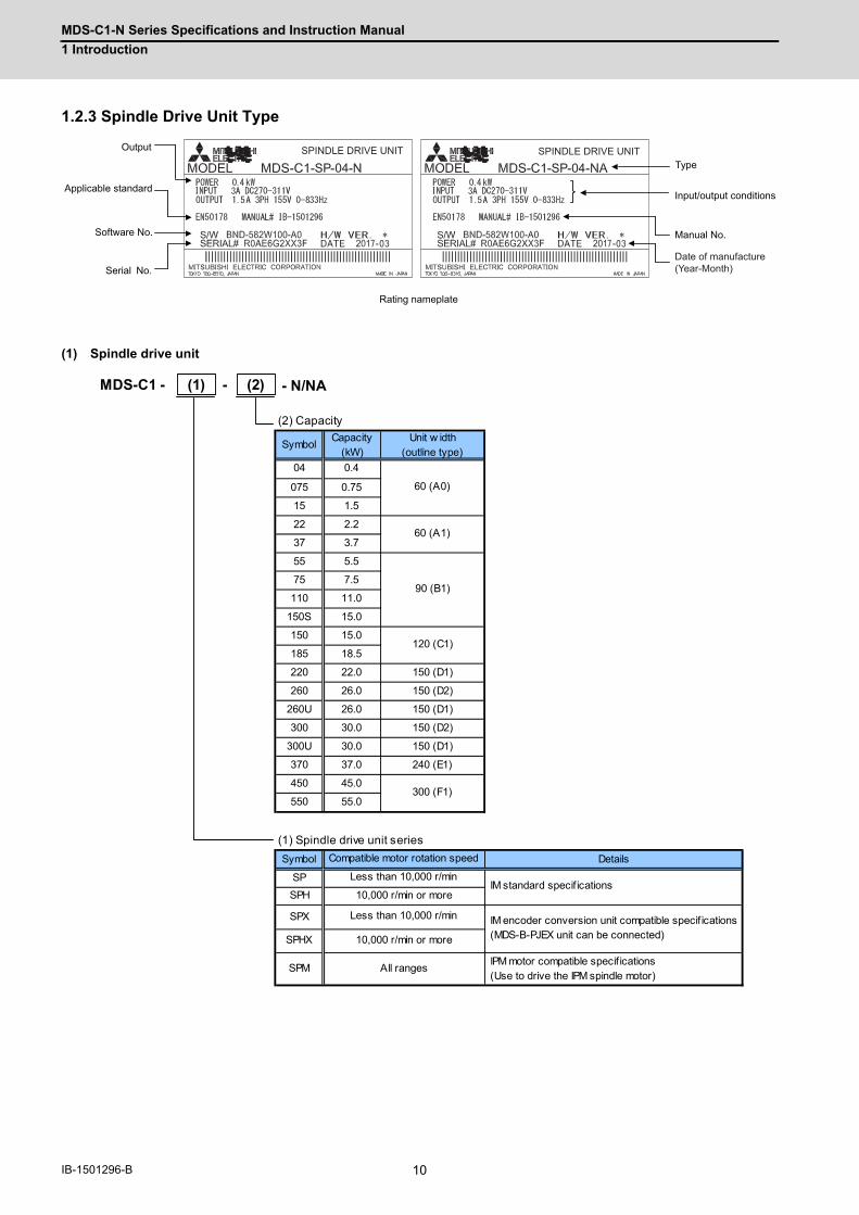
1.2.3 Spindle Drive Unit Type
(1) Spindle drive unit
SP 04 SP 04SPINDLE DRIVE UNIT SPINDLE DRIVE UNIT
Type
Input/output conditions
Software No.
Output
Applicable standard
Serial No.
Manual No.
Rating nameplate
Date of manufacture(Year-Month)
MDS-C1 -
(2) Capacity
SymbolCapacity
(kW)Unit w idth
(outline type)
04 0.4
075 0.75
15 1.5
22 2.2
37 3.7
55 5.5
75 7.5
110 11.0
150S 15.0
150 15.0
185 18.5
220 22.0 150 (D1)
260 26.0 150 (D2)
260U 26.0 150 (D1)
300 30.0 150 (D2)
300U 30.0 150 (D1)
370 37.0 240 (E1)
450 45.0
550 55.0
(1) Spindle drive unit series
Symbol Details
SP
SPH
SPX
SPHX
SPM IPM motor compatible specif ications (Use to drive the IPM spindle motor)
120 (C1)
-
60 (A0)
60 (A1)
90 (B1)
All ranges
300 (F1)
Compatible motor rotation speed
Less than 10,000 r/min IM standard specif ications
10,000 r/min or more
Less than 10,000 r/min IM encoder conversion unit compatible specif ications (MDS-B-PJEX unit can be connected)10,000 r/min or more
(1) - N/NA(2)

11 IB-1501296-B
2
Specifications

MDS-C1-N Series Specifications and Instruction Manual
2 Specifications
12IB-1501296-B
2.1 Drive unit2.1.1 Installation environment conditions
Common installation environment conditions for servo, spindle and power supply unit are shown below.
2.1.2 Servo drive unit
(1) 1-axis servo drive unit
Environ-ment
Ambient temperature Operation: 0 to 55°C (with no freezing), Storage / Transportation: -15°C to 70°C (with no freezing)
Ambient humidityOperation: 90%RH or less (with no dew condensation)
Storage / Transportation: 90%RH or less (with no dew condensation)
AtmosphereIndoors (no direct sunlight)
With no corrosive gas, inflammable gas, oil mist, dust or conductive fine particles
Altitude Operation/Storage: 1000 meters or less above sea level, Transportation: 10000 meters or less above sea level
Vibration/impact 4.9m/s2 (0.5G) / 49m/s2 (5G)
1-axis servo drive unit MDS-C1-V1- -N/NA Series
Servo drive unit type
MDS-C1-V1- -N/NA01 03 05 10 20 35 45S 45 70S 70 90 110 150
Rated output [kW] 0.1 0.3 0.5 1.0 2.0 3.5 4.5 4.5 7.0 7.0 9.0 11.0 15.0
OutputRated voltage [V] 155AC
Rated current [A] 0.95 2.9 3.4 6.8 13.0 19.0 28.0 28.0 33.5 33.5 42.0 68.0 87.0
InputRated voltage [V] 270 to 311DC
Rated current [A] 1 3 4 7 14 17 30 30 35 35 45 55 75
Control power
Voltage [V] 200AC / 200 to 230AC
Frequency [Hz] 50/60
Maximum current [A] 0.2
Maximum rush current [A] 35
Maximum rush conductivity time [ms]
6
Earth leakage current [mA] 1 (Max. 2)
Control method Sine wave PWM control method
BrakingRegenerative braking and dynamic brakes
Dynamic brakes Built-in External
External analog output 0 to +5V, 2ch (data for various adjustments)
Degree of protection IP20
Cooling method Natural-cooling Forced air cooling (fin)
Mass [kg] 2.8 3.5 4.3 5.0 5.9 6.7
Heat radiated at rated output [W] 21 27 37 53 91 132 158 185 189 284 331 465 641
Noise Less than 55dB
Unit outline dimension drawing A0 A1 B1 C1 D2

MDS-C1-N Series Specifications and Instruction Manual
2 Specifications
13 IB-1501296-B
(2) 2-axis servo drive unit
2-axis servo drive unit MDS-C1-V2- -N/NA Series
Servo drive unit type
MDS-C1-V2- -N/NA0101 0301 0303 0501 0503 0505 1003 1005 1010 2003 2010 2020 3510S 3510
Rated output [kW]0.1+
0.1
0.3+
0.1
0.3+
0.3
0.5+
0.1
0.5+
0.3
0.5+
0.5
1.0+
0.3
1.0+
0.5
1.0+
1.0
2.0+
0.3
2.0+
1.0
2.0+
2.0
3.5+
1.0
3.5+
1.0
Output
Rated voltage [V] 155AC
Rated current [A]0.95
+0.95
2.9+
0.95
2.9+
2.9
3.4+
0.95
3.4+
2.9
3.4+
3.4
6.8+
2.9
6.8+
3.4
6.8+
6.8
13.0+
2.9
13.0+
6.8
13.0+
13.0
16.0+
6.8
16.0+
6.8
InputRated voltage [V] 270 to 311AC
Rated current [A] 2 4 6 5 7 8 10 11 14 17 21 28 24 24
Control power
Voltage [V] 200AC / 200 to 230AC
Frequency [Hz] 50/60
Maximum current [A] 0.2
Maximum rush current [A] 35
Maximum rush conductivity time [ms]
6
Earth leakage current [mA] 1 (Max. 4 For two axes)
Control method Sine wave PWM control method
BrakingRegenerative braking and dynamic brakes
Dynamic brakes Built-in
External analog output 0 to +5V, 2ch (data for various adjustments)
Degree of protection IP20
Cooling method Natural-cooling Forced air cooling (fin)
Mass [kg] 3.5 4.3 5.2
Heat radiated at rated output [W] 38 41 43 46 52 62 68 78 96 127 155 178 190 190
Noise Less than 55dB
Unit outline dimension drawing A0 A1 B1
2-axis servo drive unit MDS-C1-V2- -N/NA Series
Servo drive unit type
MDS-C1-V2- -N/NA3520S 3520 3535 4520 4535 4545S 4545 7035 7045 7070S 7070 9090S
Rated output [kW]3.5+
2.0
3.5+
2.0
3.5+
3.5
4.5+
2.0
4.5+
3.5
4.5+
4.5
4.5+
4.5
7.0+
3.5
7.0+
4.5
7.0+
7.0
7.0+
7.0
9.0+
9.0
Output
Rated voltage [V] 155AC
Rated current [A]16.0
+13.0
16.0+
13.0
16.0+
16.0
28.0+
16.0
28.0+
16.0
28.0+
28.0
28.0+
28.0
33.5+
16.0
33.5+28
33.5+
33.5
33.5+
33.5
40.8+
40.8
InputRated voltage [V] 270 to 311AC
Rated current [A] 31 31 34 44 47 60 60 52 64 70 70 90
Control power
Voltage [V] 200AC / 200 to 230AC
Frequency [Hz] 50/60
Maximum current [A] 0.2
Maximum rush current [A] 35
Maximum rush conductivity time [ms]
6
Earth leakage current [mA] 1 (Max. 4 For two axes)
Control method Sine wave PWM control method
BrakingRegenerative braking and dynamic brakes
Dynamic brakes Built-in
External analog output 0 to +5V, 2ch (data for various adjustments)
Degree of protection IP20
Cooling method Forced air cooling (fin)
Mass [kg] 4.3 5.2 5.2 5.2 5.2 5.2 5.9 6.6 6.6 5.9 7.5 7.5
Heat radiated at rated output [W] 213 213 260 266 307 280 359 406 459 365 558 558
Noise Less than 55dB
Unit outline dimension drawing A1 B1 C1 B1 D2

MDS-C1-N Series Specifications and Instruction Manual
2 Specifications
14IB-1501296-B
2.1.3 Spindle Drive Unit
(1) 1-axis spindle drive unit
1-axis spindle drive unit MDS-C1-SP- -N/NA Series
Spindle drive unit type
MDS-C1-SP- -N/NA04 075 15 22 37 55 75 110 150S 150 185
Rated output [kW] 0.4 0.75 1.5 2.2 3.7 5.5 7.5 11.0 15.0 15.0 18.5
OutputRated voltage [V] AC155V
Rated current [A] 1.5 2.6 4.5 10.0 15.0 18.0 26.0 37.0 49.0 49.0 63.0
InputRated voltage [V] DC270 to 311V
Rated current [A] 3.0 4.0 7.0 13.0 17.0 20.0 30.0 41.0 58.0 58.0 76.0
Control power
Voltage [V] AC200/200 to 230V
Frequency [Hz] 50/60
Maximum current [A] 0.2
Maximum rush current [A] 35
Maximum rush conductivity time [ms]
6
Earth leakage current [mA] 6 (Max. 15)
Control method Sine wave PWM control method
Braking Regenerative braking
External analog output 0 to +10V, 2ch (data for various adjustments)
Degree of protection IP20
Cooling method Natural-cooling Forced air cooling (fin)
Mass [kg] 2.8 3.5 4.3 4.9 5.9
Heat radiated at rated output [W] 30 40 49 69 79 108 137 181 188 235 342
Noise Less than 55dB
Unit outline dimension drawing A0 A1 B1 C1
1-axis spindle drive unit MDS-C1-SP- -N/NA Series
Spindle drive unit type
MDS-C1-SP- -N/NA220 260 260U 300 300U 370 450 550
Rated output [kW] 22.0 26.0 26.0 30.0 30.0 37.0 45.0 55.0
OutputRated voltage [V] AC155V
Rated current [A] 79.0 97.0 97.0 130 130 146 173 205
InputRated voltage [V] DC270 to 311V
Rated current [A] 95.0 115 115 144 144 164 198 238
Control power
Voltage [V] AC200/200 to 230V
Frequency [Hz] 50/60
Maximum current [A] 0.2
Maximum rush current [A] 35
Maximum rush conductivity time [ms]
6
Earth leakage current [mA] 6 (Max. 15)
Control method Sine wave PWM control method
Braking Regenerative braking
External analog output 0 to +10V, 2ch (data for various adjustments)
Degree of protection IP20
Cooling method Forced air cooling (fin)
Mass [kg] 6.5 6.8 8.8 6.8 8.8 16.0 18.8
Heat radiated at rated output [W] 366 483 483 620 620 850 1000 1200
Noise Less than 55dB
Unit outline dimension drawing D1 D2 D1 D2 D1 E1 F1

MDS-C1-N Series Specifications and Instruction Manual
2 Specifications
15 IB-1501296-B
2.1.4 AC Reactor
An AC reactor must be installed for each power supply unit.
(1) 200V series
< MDS-C1-N Series >
AC reactor
AC reactor modelD-AL-
7.5K 11K 18.5K 30K 37K 45K 55K
Compatible power supply unit typeMDS-C1-CV-
37, 55, 75 110 150, 185 220, 260, 300 370 450 550
Rated capacity [kW] 7.5 11 18.5 30 37 45 55
Rated voltage [V] 200AC / 200 to 230AC
Rated current [A] 27 40 66 110 133 162 198
Frequency [Hz] 50/60 Tolerable fluctuation : between +5% and -5%
Environment
Ambient temperature Operation: -10°C to 60°C (with no freezing), Storage/Transportation: -10°C to 60°C (with no freezing)
Ambient humidityOperation: 80%RH or less (with no dew condensation),
Storage/Transportation: 80%RH or less (with no dew condensation)
AtmosphereIndoors (no direct sunlight)
With no corrosive gas, inflammable gas, oil mist or dust
AltitudeOperation/Storage: 1000 meters or less above sea level,
Transportation: 10000 meters or less above sea level
Vibration / impact 9.8m/s2 (1G) / 98m/s2 (10G)
Mass [kg] 4.2 3.7 5.3 6.1 8.6 9.7 11.5
CAUTION
B-AL or D-AL is used for MDS-C1-N Series.
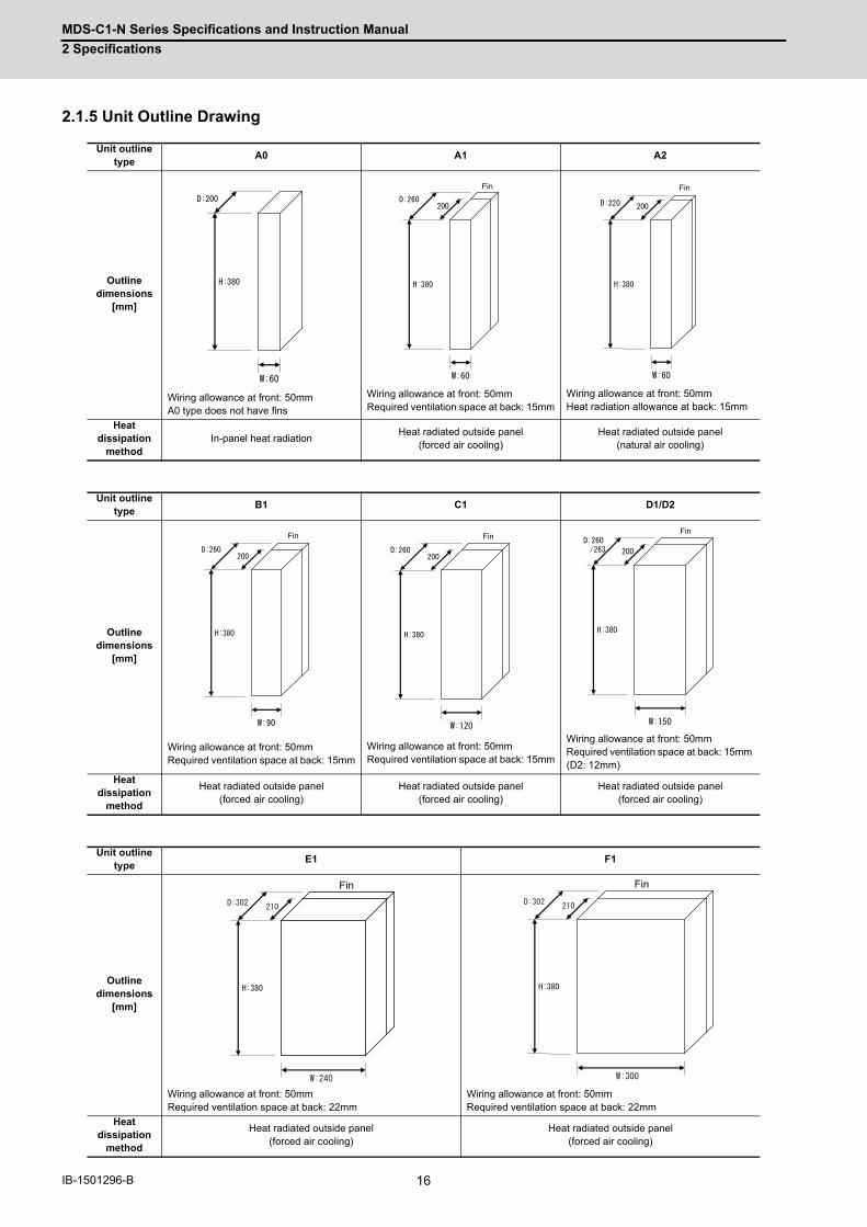
MDS-C1-N Series Specifications and Instruction Manual
2 Specifications
16IB-1501296-B
2.1.5 Unit Outline Drawing
Unit outlinetype
A0 A1 A2
Outlinedimensions
[mm]
Wiring allowance at front: 50mmA0 type does not have fins
Wiring allowance at front: 50mmRequired ventilation space at back: 15mm
Wiring allowance at front: 50mmHeat radiation allowance at back: 15mm
Heat dissipation
methodIn-panel heat radiation
Heat radiated outside panel(forced air cooling)
Heat radiated outside panel(natural air cooling)
Unit outlinetype
B1 C1 D1/D2
Outlinedimensions
[mm]
Wiring allowance at front: 50mmRequired ventilation space at back: 15mm
Wiring allowance at front: 50mmRequired ventilation space at back: 15mm
Wiring allowance at front: 50mmRequired ventilation space at back: 15mm (D2: 12mm)
Heat dissipation
method
Heat radiated outside panel(forced air cooling)
Heat radiated outside panel(forced air cooling)
Heat radiated outside panel(forced air cooling)
Unit outlinetype
E1 F1
Outlinedimensions
[mm]
Wiring allowance at front: 50mmRequired ventilation space at back: 22mm
Wiring allowance at front: 50mmRequired ventilation space at back: 22mm
Heat dissipation
method
Heat radiated outside panel(forced air cooling)
Heat radiated outside panel(forced air cooling)
Fin Fin
Fin Fin Fin
Fin Fin

MDS-C1-N Series Specifications and Instruction Manual
2 Specifications
17 IB-1501296-B
2.1.6 Unit Outline Dimension Drawing
MDS-C1-Vx--N/NA Series
(1) 60 width Without fin
20 180
200
195
380
350
1515
24
22
11
124.
5
92
16
360
6
60
10
30
70
360
MDS-C1-V1-01-N/NAMDS-C1-V1-03-N/NAMDS-C1-V1-05-N/NAMDS-C1-V1-10-N/NA
MDS-C1-V2-0101-N/NAMDS-C1-V2-0301-N/NAMDS-C1-V2-0303-N/NAMDS-C1-V2-0501-N/NAMDS-C1-V2-0503-N/NAMDS-C1-V2-0505-N/NAMDS-C1-V2-1003-N/NAMDS-C1-V2-1005-N/NAMDS-C1-V2-1010-N/NA
MDS-C1-SP-04-N/NAMDS-C1-SP-075-N/NAMDS-C1-SP-15-N/NA
Φ6 hole
(Note 1) The square hole does not need to be machined.
(Note 1)
Panel mounting hole machining drawing
(State with terminal block cover removed)
2-M5 screw hole
3-M4 screw
2-M4 screw
- For MDS-C1-V1--N/NA
- For MDS-C1-V2--N/NA
6-M4 screw 3-M4 screw
[Unit: mm]
Terminal block cover
2-M6 screw
2-M4 screw
(Wiring allowance)

MDS-C1-N Series Specifications and Instruction Manual
2 Specifications
18IB-1501296-B
(2) 60 width
15
342
360
52
70
18020
260
10
6
30
60
360
24
11
124.
5
16
22
92
15
60
195
380
350
15
MDS-C1-V1-20-N/NAMDS-C1-V1-35-N/NAMDS-C1-V1-45S-N/NA
MDS-C1-V2-2010-N/NAMDS-C1-V2-2020-N/NAMDS-C1-V2-3510S-N/NAMDS-C1-V2-3520S-N/NA
MDS-C1-SP-22-N/NAMDS-C1-SP-37-N/NA
(Note 1) Attach packing around the square hole for sealing.(Note 2) The MDS-C1-V1-20-N does not have a fan at the top.
Note that the MDS-C1-V1-45S-N uses an 3-M5 screw
2-M4 screw
6-M4 screw
3-M4 screw
Panel mounting hole machining drawing
Square hole
(Note 1)
2-M5 screw hole
- For MDS-C1-V2--N/NA
- For MDS-C1-V1--N/NA
(State with terminal block cover removed) Required wind
passage space
Terminal block cover
2-M6 screw
2-M4 screw
(Note 2)
Intake
Φ6 hole
Intake
3-M4 screw
[Unit: mm]
(Wiring allowance)

MDS-C1-N Series Specifications and Instruction Manual
2 Specifications
19 IB-1501296-B
(3) 90 width
15
342
360
82
1036
0
6
45
90
24
1192
16
22
124.
5
70
60
260
20 180 15
195
1535
0
380
MDS-C1-V1-45-N/NA MDS-C1-V1-70S-N/NA
Panel mounting hole machining drawing
(State with terminal block cover removed)
(Note 1) Attach packing around the square hole for sealing.
3-M5 screw
Square hole
(Note 1)
2-M5 screw hole
Terminal block cover
Required wind passage space
Intake
2-M6 screw
Φ6 hole
2-M4 screw
Intake
2-M5 screw
[Unit: mm](Wiring
allowance)

MDS-C1-N Series Specifications and Instruction Manual
2 Specifications
20IB-1501296-B
342
360
82
15
10
6
45
90
360
16
24
11
22
124.
5
92
70
195
380
350
60
260
1518020
15
MDS-C1-V2-3510-N/NAMDS-C1-V2-3520-N/NAMDS-C1-V2-3535-N/NAMDS-C1-V2-4520-N/NAMDS-C1-V2-4535-N/NAMDS-C1-V2-4545S-N/NA MDS-C1-V2-7070S-N/NA
(Note 1) Attach packing around the square hole for sealing.
6-M4 screw
Panel mounting hole machining drawing
Square hole
(Note 1)
2-M5 screw hole
Required wind passage space
Terminal block cover
2-M6 screw
Intake
(State with terminal block cover removed)
Φ6 hole
Intake
2-M4 screw
3-M4 screw
[Unit: mm]
(Wiring allowance)

MDS-C1-N Series Specifications and Instruction Manual
2 Specifications
21 IB-1501296-B
15
342
360
82
1036
0
645
90
2411
92
1622
124.
5
70
60260
20 180 15
195
1535
038
0
MDS-C1-SP-55-N/NAMDS-C1-SP-75-N/NAMDS-C1-SP-110-N/NA
Φ6
2-M6
2-M4
MDS-C1-SP-150S-N/NA
3-M5
2-M5
(Note 1) Attach packing around the square hole for sealing.
screw
Panel mounting hole machining drawing
Square hole
(Note 1)
2-M5 screw hole
Required wind passage space
Terminal block cover
screw
Intake
(State with terminal block cover removed)
hole
Intake
screw
screw
[Unit: mm]
(Wiring allowance)

MDS-C1-N Series Specifications and Instruction Manual
2 Specifications
22IB-1501296-B
(4) 120 width
15
342
360
112
24
11
52
46
6
60
120
60
360
10
124.
5
92
70
195
20 180
260
1515
350
380
MDS-C1-V1-70-N/NAMDS-C1-V1-90-N/NA
MDS-C1-SP-150-N/NAMDS-C1-SP-185-N/NA
(Note 1) Attach packing around the square hole for sealing.
3-M5 screw
Panel mounting hole machining drawing
Square hole
(Note 1)
2-M5 screw hole
Terminal block cover Required wind
passage space
Intake
2-M6 screw
(State with terminal block cover removed)
Φ6 hole
2-M4 screw
Intake
2-M5 screw
[Unit: mm]
(Wiring allowance)

MDS-C1-N Series Specifications and Instruction Manual
2 Specifications
23 IB-1501296-B
MDS-C1-V2-4545-N/NAMDS-C1-V2-7035-N/NAMDS-C1-V2-7045-N/NA
380
15
1036
0
6
60
120
24
11
124.
5
92
52
46
70
15
195
350
20 180 60 15
260
342
360
112(Note 1) Attach packing around the square hole for sealing.
6-M4 screw
Panel mounting hole machining drawing
Square hole
(Note 1)
2-M5 screw hole
Terminal block cover
Required wind passage space
Intake
2-M6 screw
Φ6 hole
(State with terminal block cover removed)
2-M4 screw
Intake
3-M4 screw
[Unit: mm]
(Wiring allowance)

MDS-C1-N Series Specifications and Instruction Manual
2 Specifications
24IB-1501296-B
(5) 150 width
60
360
342
142
6 6
45 60
150
10
24
11
52
46
360
124.
5
92
70
15
380
1535
0
195
60 1518020
260
MDS-C1-V2-7070-N/NAMDS-C1-V2-9090S-N/NA
MDS-C1-SP-260U-N/NAMDS-C1-SP-300U-N/NA
MDS-C1-SP-220-N/NA
(Note 1) Attach packing around the square hole for sealing.
6-M4 screw
Panel mounting hole machining drawing
Square hole
(Note 1)
4-M5 screw hole
Required wind passage space
Terminal block cover
Intake
2-M6 screw
(State with terminal block cover removed)
2-Φ6 hole
2-M4 screw
Intake
3-M4 screw
[Unit: mm](Wiring
allowance)

MDS-C1-N Series Specifications and Instruction Manual
2 Specifications
25 IB-1501296-B
6 6
45 60
150
1192
24
52
46
124.
5
1036
0
70
18020 12
15
195
1935
0
384
263
63
60
360
342
142
MDS-C1-V1-110-N/NAMDS-C1-V1-150-N/NA
MDS-C1-SP-260-N/NAMDS-C1-SP-300-N/NA
Panel mounting hole machining drawing
(Note 1) Attach packing around the square hole for sealing.
3-M8 screw
Square hole
(Note 1)
4-M5 screw hole
Terminal block cover
2-M6 screw
Heat dissipation allowance
Intake
Exhaust
(State with terminal block cover removed)
2-Φ6 hole
2-M4 screw
2-M8 screw
[Unit: mm]
(Wiring allowance)

MDS-C1-N Series Specifications and Instruction Manual
2 Specifications
26IB-1501296-B
(6) 240 width
341
222
180
210 92
80
22
60 120 60
6
240
4-M5120
360
118
3726.5
1036
010
200 11
30.5
MDS-C1-SP-370-N/NA
2-M4
Panel mounting hole machining drawing
3-M8 screwSquare hole
screw hole
2-M10 screw Intake
(State with terminal block cover removed)
2-Φ6 hole
screw
2-M8 screw
(Required wind passage space)
[Unit: mm]
(Wiring allowance)

MDS-C1-N Series Specifications and Instruction Manual
2 Specifications
27 IB-1501296-B
(7) 300 width
180
210
178.5 92
80
22
118
37
1036
010
30.5
11
26.5
260
60 180 60
6
300
2-M10
2-M10
3-M10341
282
4-M5180
360
MDS-C1-SP-450-N/NAMDS-C1-SP-550-N/NA
Panel mounting hole machining drawing
screwSquare
hole
screw hole
(State with terminal block cover removed)
2-Φ6 hole
2-M4 screw
screw
(Required wind passage space)
Intake
[Unit: mm]
(Wiring allowance)
screw

MDS-C1-N Series Specifications and Instruction Manual
2 Specifications
28IB-1501296-B
2.1.7 AC Reactor Outline Dimension Drawing[Unit: mm]
D-AL-7.5K D-AL-11K
D-AL-18.5K D-AL-30K
D-AL-37K
N.P
55 1.5165
155
82 1.5
130175
20
L11 L21 L31
L12 L22 L32
FG2-M4M5 12
(Tightening torque: 2.0Nm)
Terminal screw 6-M5 12
(with cover)Nameplate
4-M6 hole
Terminal plate
Groundingposition
Terminalassignment seal Cover
Bar code
of manufactureSerial number
N.P
55 1.5165
155
75 1.5
130175
20
L11 L21 L31
L12 L22 L32
FG 2-M4M5 12
Terminal screw 6-M5 12
Terminal plate(with cover)
position
Nameplate
4-M6 holeGrounding
Terminalassignment seal Cover
Bar code
Serial numberof manufacture
(Tightening torque: 2.0Nm)
N.P
55 1.5165
155
105 1.5
175 130
20
L11 L21 L31
L12 L22 L32
FG 2-M4M5 12
4-M6 hole
Terminal screw 6-M6 16
(with cover)
position
Nameplate
Terminal plate
Grounding
assignment sealTerminal Cover
of manufacture
Bar code
Serial number
(Tightening torque: 4.0Nm)
N.P
55 1.5165
155
110 1.5140
175 130
20
L11 L21 L31
L12 L22 L32
FG 2-M4M5 12
4-M6 holeTerminal screw 6-M6 16
Nameplate
positionGrounding
(with cover)Terminal plate
Terminalassignment seal
Cover
Bar code
of manufactureSerial number
(Tightening torque: 4.0Nm)
N.P
70 1.5215 2.5
175
110 1.5150
130
20
L11 L21 L31
L12 L22 L32
FG 2-M4M5 12
4-M6 holeTerminal screw 6-M6 16
Nameplate
positionGrounding
(with cover)Terminal plate
Cover
Bar code
Terminalassignment seal
of manufactureSerial number
(Tightening torque: 4.0Nm)

MDS-C1-N Series Specifications and Instruction Manual
2 Specifications
29 IB-1501296-B
[Unit: mm]
D-AL-45K D-AL-55K
N.P
70 1.5215 2.5
175
120 1.5160
13020
L11 L21 L31
L12 L22 L32
FG 2-M4M5 12
4-M6 holeTerminal screw 6-M6 16
Cover
Bar code
Nameplate(with cover)Terminal plate
positionGrounding Terminal
assignment seal
of manufactureSerial number
(Tightening torque: 4.0Nm)
200 1.5220 2.5
195
2.5
120 1.5
230
L11 L21 L31
L12 L22 L32
FG 2-M4M5 12
Terminal screw 6-M10 20
4-M8 hole
Nameplate
positionGrounding
(with cover)Terminal plate
of manufactureSerial number
Terminalassignment seal
Cover
Bar code
(Tightening torque: 11.0Nm)

MDS-C1-N Series Specifications and Instruction Manual
2 Specifications
30IB-1501296-B
2.1.8 Explanation of Each Part
(1) 200V series
(a) Explanation of each servo drive unit part
The connector and terminal block layout may differ according to the unit being used. Refer to each unit outline
drawing for details.
< Each part name >
(Note) The connector names differ for the V1 drive unit. The CN2L/CN3L are named CN2/CN3, and LU, LV and LW
terminals are named U, V and W.
< Screw size >
(Note) The V1-45S UVW terminal screw size is M5, the same as V1-45.
Name Description
(1)
Controlcircuit
LED --- Unit status indication LED
(2) SW1 --- Axis No. setting switch (Left: L axis, Right: M axis)
(3) CN1A --- NC or upward axis communication connector
(4) CN1B --- Battery unit/Terminator/Lower axis communication connector
(5) CN9 --- Analog output connector
(6) CN4 --- Power supply communication connector
(7) CN2L --- Motor side encoder connection connector (L axis)
(8) CN3L --- Machine side encoder connection connector (L axis)
(9) CN2M --- Motor side encoder connection connector (M axis)
(10) CN3M --- Machine side encoder connection connector (M axis)
(11) CN20 --- Motor brake/dynamic brake control connector (for V1-110/150)
(12)
Main circuit
TE2L+L-
Converter voltage input terminal (DC input)
(13) TE3L11L21
Control power input terminal (single-phase AC input)
(14)TE1
LU, LV, LWMotor power output terminal (3-phase AC output)
(15) MU, MV, MW
(16) PE Grounding terminal
1-axis servo drive unit MDS-C1-V1- 2-axis servo drive unit MDS-C1-V2-
Type 01 to 35, 45S 45, 70S 70 to 90 110 to 1500101 to 20203510S, 3520S
3510 to 4545S,7070S
4545 to 7045 7070
Unit width (mm) 60 90 120 150 60 90 120 150
(12) L+, L- M6×14
(13) L11, L21 M4×10
(14) LU, LV, LW(15) MU, MV, MW
M4×12(Note)
M5×12 M8×14 M4×12
(16) M4×8 M5×12 M8×14 M4×8
(1)
(3)
(5)
(7)
(12)
(13)
(16)
(14)
(2)
(4)
(6)
(11)
(8)
MDS-C1-V1--N/NA
(1) (2)
(3)
(5)
(7)
(9)
(12)
(15)
(14)
(4)
(6)
(11)
(8)
(10)
(13)
(16)
MDS-C1-V2--N/NA

MDS-C1-N Series Specifications and Instruction Manual
2 Specifications
31 IB-1501296-B
(b) Explanation of each spindle drive unit part
The connector and terminal block layout may differ according to the unit being used. Refer to each unit outline
drawing for details.
< Each part name >
< Screw size >
Name Description
(1)
Controlcircuit
LED --- Unit status indication LED
(2) SW1 --- Axis No. setting switch
(3) SW2 --- Model selection setting switch
(4) CN1A --- NC or upward axis communication connector
(5) CN1B --- Battery unit/Terminator/Lower axis communication connector
(6) CN9 --- Analog output connector
(7) CN4 --- Power supply communication connector
(8) CN5 --- Internal PLG encoder connection connector
(9) CN6 --- Magnetic sensor connection connector
(10) CN7 --- C axis control encoder connection connector (Motor side encoder connection connector)
(11) CN8 --- CNC connection connector
(12)
Main circuit
TE2L+L-
Converter voltage input terminal (DC input)
(13) TE3L11L21
Control power input terminal (single-phase AC input)
(14) TE1 LU, LV, LW Motor power output terminal (3-phase AC output)
(15) PE Grounding terminal
Spindle drive unit MDS-C1-SP-
Type04, 075, 15
22, 3755, 75, 110 150S 150, 185
220, 260U,300U
260, 300 370 450, 550
Unit width (mm) 60 90 90 120 150 150 240 300
(12) L+, L- M6×16 M10×20
(13) L11, L21 M4×12 M4×10
(14) LU, LV, LW M4×12 M5×12 M8×16 M8×15 M10×20
(15) M4×8 M5×8 M8×14 M8×16 M10×20
(1)(2)
(4)
(6)
(8)
(10)
(12)
(14)
(5)
(7)
(9)
(11)
(13)
(15)
MDS-C1-SP--N/NA
(3) (1) (3)
(4)
(6)
(8)
(10)
(5)
(7)
(9)
(11)
(12)
(13)
(2)
(15)(14)

MDS-C1-N Series Specifications and Instruction Manual
2 Specifications
32IB-1501296-B
2.1.9 Setting DIP Switch
As for spindle drive unit, setting the DIP switches is necessary prior to turning ON the power depending on the target
model. Setting of the DIP switches at the time of turning ON the power is validated. Set the model to be used before
turning ON the power. All the switches of the DIP switches are OFF at the initial setting.
< Set list >
(Note) All the other settings lead to Alarm 7F (Power reboot request).
SW1 SW2 SW3 SW4 Replacement target model
ON OFF OFF OFF MDS-A/B/C1-SP-
OFF ON OFF OFF MDS-A/B/C1-SPH-
OFF OFF ON OFF MDS-B/C1-SPX
OFF OFF OFF ON MDS-B/C1-SPM-
MDS-B/C1-SPM-MDS-B/C1-SPX-MDS-A/B/C1-SPH-MDS-A/B/C1-SP-
SW1 SW2 SW3 SW4
Set Set
Set Set
The switches are OFF when facing bottom as illustrated.

MDS-C1-N Series Specifications and Instruction Manual
2 Specifications
33 IB-1501296-B
< Combination of the replacement target model >
Setting of the DIP switches differs depending on the replacement target model.
Set them according to the target model and the operation conditions.
(Note 1) Do not set the switches of the unit for which PJEX is not used.
(Note 2) The alarm differs depending on the SP037 (SFNC5) setting.
SP037: bit0=1 (Encoder orientation valid) … Alarm No.: 89
SP037: bit2=1 (PLG orientation valid)… Alarm No.: 37
< Details of alarm No. >
Investigation details for the DIP switch setting are added to the following alarms.
Replacement target
Spindle motorApplication
SW1 (C1-SP- -N/NA) SW2 (C1-SPH- -N/NA) SW3 (C1-SPX- -N/NA) SW4 (C1-SPM- -N/NA)
SP IM motor Usable Not usable
Not usable(Alarm No.: 37)
(Alarm No.: 89)Note 2
Not usable(Alarm No.: 7F)
SPH IM motor Not usable Usable
Not usable(Alarm No.: 37)
(Alarm No.: 89)Note 2
Not usable(Alarm No.: 7F)
SPX(SPHX)
IM motor
(PJEX is connected)Note 1Not usable
(Alarm No.: 21)Not usable
(Alarm No.: 21)Usable
Not usable(Alarm No.: 7F)
SPM IPM motorNot usable
(Alarm No.: 7F)Not usable
(Alarm No.: 7F)Not usable
(Alarm No.: 7F)Usable
Alarm No.21
Machine side encoder: No signal 2:
Spindle: The encoder no-signal was detected.
Alarm No.37
Initial parameter error:
An incorrect parameter was detected among the parameters received from the CNC at the power ON."S02 Initial parameter error ####" appears on the NC screen. (####: Error parameter No.)
Alarm No.7F
Power reboot request:
A mismatch in the program mode selection was detected. Turn the drive unit power ON again.
Alarm No.89
Encoder converter unit 2 connection error:
Initial communication with the MDS-B-PJEX was not possible.
Investigation details Investigation results Remedies SV SP
Check the used model setting of the DIP switches.The used model setting of the DIP switches and the parameter are mismatched.
Check the used model setting of the DIP switches.

MDS-C1-N Series Specifications and Instruction Manual
2 Specifications
34IB-1501296-B

35 IB-1501296-B
3
Characteristics
MDS-C1-N Series Specifications and Instruction Manual
3 Characteristics
36IB-1501296-B
3.1 Drive Unit3.1.1 Environmental Conditions
(Note) When installing the machine at 1,000m or more above sea level, the heat dissipation characteristics
will drop as the altitude increases in proportion to the air density. The ambient temperature drops 1%
with every 100m increase in altitude.
When installing the machine at 1,800m altitude, the heating value of the drive unit must be reduced
to 92% or less. The heating value is proportional to the square of the current, and required current
decreasing rate follows the expression below.
Therefore, use the unit with the reduced effective load rate to 95% or less.
Environment Conditions
Ambient temperature 0°C to +55°C (with no freezing)
Ambient humidity 90% RH or less (with no dew condensation)
Storage temperature -15°C to +70°C (with no freezing)
Storage humidity 90% RH or less (with no dew condensation)
AtmosphereIndoors (no direct sunlight);
no corrosive gas, inflammable gas, oil mist, dust or conductive fine particles
AltitudeOperation/storage: 1000m or less above sea levelTransportation: 10000m or less above sea level
Vibration Operation/storage: 4.9m/s2 (0.5G) or less Transportation: 49m/s2(5G) or less
0.92 = 0.95Required current decreasing rate =

MDS-C1-N Series Specifications and Instruction Manual
3 Characteristics
37 IB-1501296-B
3.1.2 Heating Value
Each heating value is calculated with the following values.
The values for the servo drive unit apply at the stall output. The values for the spindle drive unit apply for the continuous rated
output.
(Note 1) The values for the spindle drive unit are the heating value at the continuous rated output, and the values for the
servo drive unit are the heating values at the stall output when operating in the high-gain mode. The heating value
when operating the servo drive unit in the standard mode (MDS-B compatible mode) is lower than the MDS-B
Series heating value. However, with the new design, the standard operation mode will not presumably be used, so
the data has been eliminated.
(Note 2) The total heating value for the unit is the total sum of the heating values for the above corresponding units which
are mounted in the actual machine.
(Note 3) When designing the panel for sealed mounting, take the actual load rate into consideration, and calculate the
heating value inside the servo drive unit panel with the following expression:
If the load rate is clearly larger than 0.5, substitute that load rate for (× 0.5) in the above expression.
Example) When the V1-35 servo drive unit is mounted
Heating value in panel (at rated output) = 30(W)
Thus, the heating value in the panel (considering the load rate) is 30 × 0.5 = 15(W)
Servo drive unit Spindle drive unit
Type
MDS-C1- -N/NA
Heating value [W]Type
MDS-C1- -N/NA
Heating value [W]Type
MDS-C1- -N/NA
Heating value [W]
Inside panel
Outside panel
Inside panel
Outside panel
Inside panel
Outside panel
V1-01 21 0 V2-0101 38 0 SP-04 30 0
V1-03 27 0 V2-0301 41 0 SP-075 40 0
V1-05 37 0 V2-0303 43 0 SP-15 49 0
V1-10 53 0 V2-0501 46 0 SP-22 26 42
V1-20 25 66 V2-0503 52 0 SP-37 28 51
V1-35 30 102 V2-0505 62 0 SP-55 31 76
V1-45S 34 124 V2-1005 78 0 SP-75 35 102
V1-45 37 148 V2-1010 96 0 SP-110 41 140
V1-70S 38 151 V2-2010 37 117 SP-150S 48 140
V1-70 50 234 V2-2020 41 137 SP-150 48 187
V1-90 56 275 V2-3510S 44 146 SP-185 62 280
V1-110 74 392 V2-3510 42 148 SP-220 65 301
V1-150 96 545 V2-3520S 48 165 SP-260 80 403
V2-3520 45 168 SP-260U 80 403
V2-3535 51 209 SP-300 98 522
V2-4520 52 214 SP-300U 98 522
V2-4535 57 249 SP-370 243 607
V2-4545S 55 225 SP-450 280 720
V2-4545 64 295 SP-550 330 870
V2-7035 70 336
V2-7045 77 382
V2-7070S 65 300
V2-7070 90 468
V2-9090S 65 300
Heating value inside servo drive unit panel (considering load rate) =
Heating value in panel obtained from above table × 0.5

MDS-C1-N Series Specifications and Instruction Manual
3 Characteristics
38IB-1501296-B

39 IB-1501296-B
4
Dedicated Options

MDS-C1-N Series Specifications and Instruction Manual
4 Dedicated Options
40IB-1501296-B
4.1 Drive Unit4.1.1 Dynamic Brake Unit (MDS-B-DBU)
The MDS-C1-V1-110 and MDS-C1-V1-150 units do not have dynamic brakes built in, so install an external dynamic
brake unit.
(1) Specifications
(2) Outline dimension drawings
MDS-B-DBU-150[Unit:mm]
Type Coil specifications Compatible drive unit Weight
MDS-B-DBU-150
DC24V 160mA
MDS-C1-V1-110/150
2kg
U V W
FG a b 13 14
10
200
20
20
5
190
200
5 5
20
140

MDS-C1-N Series Specifications and Instruction Manual
4 Dedicated Options
41 IB-1501296-B
(3) Connecting with the servo drive unit
CAUTION
Correctly wire the dynamic brake unit to the servo drive unit.
Do not use for applications other than emergencies (normal braking, etc.). The internal resistor could heat up, and lead to
fires or faults.
POINT
When you use a motor with a brake, please wire (between 1pin and 3pin) for the CN20 connector.
V
W
U
14
13
b
a
C SK
R (0.2 )
VW
21
3
U
U V W a b
23
NCab1314
56
21
34
DC24V GND
CNU20S(AWG14)(CN20)
23
M
(MDS-B-DBU-150)
DBUDC24V
MBR11
Brake connector
Externalpower supply
Twist wire
Control terminal block (M3)
Dynamic brake unit
Power terminalblock (M3)
Internal circuit diagram
Servomotor
Pin Name
Terminal Name
Terminal Name
Term
inal
blo
ck
To a motor brake

MDS-C1-N Series Specifications and Instruction Manual
4 Dedicated Options
42IB-1501296-B

43
付録 Ap1 章
43 IB-1501296-B
Appendix 1
EMC Installation Guidelines

MDS-C1-N Series Specifications and Instruction Manual
Appendix 1 EMC Installation Guidelines
44IB-1501296-B
Appendix 1.1 IntroductionAs the NC unit is a component designed to control machine tools, it is believed to be out of the direct EMC Instruction subject.
However, we would like to introduce the following measure plans to backup EMC Instruction compliance of the machine tool
as the NC unit is a major component of the machine tools.
[1] Methods for installation in control/operation panel
[2] Methods of wiring cable outside of panel
[3] Introduction of countermeasure parts
Mitsubishi is carrying out tests to confirm the compliance to the EMC Standards under the environment described in this
manual. However, the level of the noise will differ according to the equipment type and layout, control panel structure and
wiring lead-in, etc. Thus, we ask that the final noise level be confirmed by the machine tool builder.
For measures for CNC, refer to "EMC INSTALLATION GUIDELINES" of each NC Connection Manual.
Appendix 1.2 EMC InstructionsThe EMC Instructions regulate mainly the following two withstand levels.
Emission ..... Capacity to prevent output of obstructive noise that adversely affects external sources.
Immunity ..... Capacity not to malfunction due to obstructive noise from external sources.
The details of each level are classified in the table below. It is assumed that the Standards and test details required for a
machine tool are about the same as these.
Class Name DetailsGeneric
Standard
Standards for determining test
and measurement
Emission
Radiated noise Electromagnetic noise radiated through the air EN61000-6-4(General industrial machine)EN61800-3(Motor control unit)
-----Conductive noise
Electromagnetic noise discharged from power line
Immunity
Static electricity electrical discharge immunity test
(Example) Withstand level of discharge of electricity charged in a human body.
EN61000-6-2(General industrial machine)EN61800-3(Motor control unit)
EN61000-4-2
Radiated radio-frequency magnetic field immunity test
(Example) Simulation of immunity from digital wireless transmitters
EN61000-4-3
Electrical fast transient/burst immunity test
(Example) Withstand level of noise from relays or connecting/disconnecting live wires
EN61000-4-4
Immunity to conducted disturbance induced by radio-frequency magnetic field
(Example) Withstand level of noise entering through power line, etc.
EN61000-4-6
Power supply frequency field immunity test
(Example) 50/60Hz power frequency noise EN61000-4-8
Immunity test for voltage dip, short-time power failure and voltage fluctuation
(Example) Power voltage drop withstand level EN61000-4-11
Surge immunity test(Example) Withstand level of noise caused by lightning
EN61000-4-5

MDS-C1-N Series Specifications and Instruction Manual
Appendix 1 EMC Installation Guidelines
45 IB-1501296-B
Appendix 1.3 EMC MeasuresThe main items relating to EMC measures include the following.
[1] Store the device in an electrically sealed metal panel.
[2] Earth all conductors that are floating electrically. (Lower the impedance.)
[3] Wire the power line separated from the signal wire as far as possible.
[4] Use shielded wires for the cables wired outside of the panel.
[5] Install a noise filter.
Ensure the following items to suppress noise radiated outside of the panel.
[1] Accurately ground the devices.
[2] Clamp shielded wires in the control panel.
[3] Increase the panel's electrical seal. Reduce the gap and hole size.
Note that the electromagnetic noise radiated in the air is greatly affected by the clearance of the panel and the
quality of the cable shield.
Appendix 1.4 Measures for Panel StructureThe design of the panel is a very important factor for the EMC measures, so take the following measures into consideration.
Appendix 1.4.1 Measures for Control Panel Unit
[1] Use metal for all materials configuring the panel.
[2] For the joining of the top plate and side plates, etc., mask the contact surface with paint, and fix with welding or
screws so that the impedance is reduced. In either case, keep the joining clearance to a max. of 20cm for a better
effect.
Note that if the plate warps due to the screw fixing, etc., creating a clearance, noise could leak from that place.
[3] Plate the earth plate (with nickel, tin), and connect the connections with a low impedance.
[4] If there is a opening on the panel surface, such as the ventilation holes, cover it with a metal plate or expanded
metal.
Make sure not to connect using metal or a conductor without peeling off the surface, which results in an insufficient
electrical connection. (ex. connection by putting painted surfaces together)
Painting mask
Max. joining clearance 20cm or less
)
3cm~5cm
Metal plate or expanded metal
Painting maskExample
* Provide electrical conductance
Opening

MDS-C1-N Series Specifications and Instruction Manual
Appendix 1 EMC Installation Guidelines
46IB-1501296-B
Appendix 1.4.2 Measures for Door
[1] Use metal for all materials configuring the door.
[2] Use an EMI gasket or conductive packing for the contact between the door and control panel unit.
[3] The EMI gasket or conductive packing must contact at a uniform and correct position of the metal surface of the
control panel unit.
[4] The surface of the control panel unit contacted with the EMI gasket or conductive packing must have conductance
treatment.
(Example) Weld (or screw) a plate that is plated (with nickel, tin).
[5] As a method other than the above, the control panel unit and door can be connected with a plain braided wire. In
this case, the panel and door should be contacted at as many points as possible.
Appendix 1.4.3 Measures for Operation Board Panel
[1] Always connect the operation board and indicator with an earthing wire.
[2] If the operation board panel has a door, use an EMI gasket or conductive packing between the door and panel to
provide electrical conductance in the same manner as the control panel.
[3] Connect the operation board panel and control panel with a sufficiently thick and short earthing wire.
Appendix 1.4.4 Shielding of the Power Supply Input Section
[1] Separate the input power supply section from other parts in the control panel so that the input power supply cable
will not be contaminated by radiated noise.
[2] Do not lead the power line through the panel without passing it through a filter.
EMI gasket
Packing
Control panel
Door
Carry out conductance treatment on sections that the EMI gasket contacts.
Control panel Control panel
Drive unit Drive unit
Radiated noise
Radiated noise
AC input AC inputBreaker BreakerPower line filter
Power line filter
Shielding plate
The power supply line noise is eliminatedby the filter, but cable contains noiseagain because of the noise radiated in thecontrol panel.
Use a metal plate, etc., for the shieldingpartition. Make sure not to create aclearance.

MDS-C1-N Series Specifications and Instruction Manual
Appendix 1 EMC Installation Guidelines
47 IB-1501296-B
Appendix 1.5 Measures for Various CablesThe various cables act as antennas for the noise and discharge the noise externally. Thus appropriate treatment is required to
avoid the noise.
The wiring between the drive unit and motor act as an extremely powerful noise source, so apply the following measures.
Appendix 1.5.1 Measures for Wiring in Panel
[1] If the cables are led unnecessarily in the panel, they will easily pick up the radiated noise. Thus, keep the wiring
length as short as possible.
[2] The noise from other devices will enter the cable and be discharged externally, so avoid internal wiring near the
openings.
[3] Connect the control device earthing terminal and earthing plate with a thick wire. Take care to the leading of the
wire.
Appendix 1.5.2 Measures for Shield Treatment
Common items
Use of shield clamp fittings is recommended for treating the shields. The fittings are available as options, so order as
required. (Refer to the section "Shield Clamp Fitting" in this chapter.)
Clamp the shield at a position within 10cm from the panel lead out port.
POINT
1. When leading the cables, including the grounding wire (FG), outside of the panel, clamp the cables near the panel outlet
(recommendation: within 10cm).
2. When using a metal duct or conduit, the cables do not need to be clamped near the panel outlet.
3. When leading cables not having shields outside the panel, follow the instructions given for each cable. (Installation of a
ferrite core, etc., may be required.)
Device Device Device Device Device Device
Noise Noise
Noise
Device Device Device Device
Control panel Control panel

MDS-C1-N Series Specifications and Instruction Manual
Appendix 1 EMC Installation Guidelines
48IB-1501296-B
Appendix 1.5.3 Servo/Spindle Motor Power Cable
Power cable for servo motor
Power cable for spindle motor
[1] Use four wires (3-phase + earthing) for the power cable that are completely shielded and free from breaks.
[2] Earth the shield on both the control panel side and motor chassis side. The shield earth position on the drive unit
side must be 10cm or less from the control panel.
[3] Earth the shield with a metal P clip or U clip.
(A cable clamp fitting can be used depending on the wire size.)
[4] Directly earth the shield. Do not solder the braided shield onto a wire and earth the end of the wire.
[5] When not using a shield cable for the power cable, use a conventional cabtyre cable. Use a metal conduit outside
the cable.
[6] Earth the power cable on the control panel side at the contact surface of the conduit connector and control panel.
(Mask the side wall of the control panel with paint.)
[7] Follow the treatment shown in the example for the conduit connector to earth the power cable on the motor side.
(Example: Use a clamp fitting, etc.)
To drive unit
Earth with P or U clip
Cannon connector
Shield cableServo motor
Control panel Earth with paint mask
Conduit connector
Servo motorCabtyre cable
Conduit
Using shield cable Using conduit
Control panel
To drive unit Cannon connector
10cm or lessAs close as possible
Control panel
Terminal box
Spindle motor
Earth with paint mask
Conduit connector
Control panel
To drive unit To drive unit
Using shield cable
Shield cable
Earth with P or U clip
Using conduit
Cabtyre cable
Spindle motorConduit
Terminal box10cm or lessAs close as possible
Solder
Earth example with P clip Earth example with U clip Earth example with wire soldering
Earth (Wire it as short and thick as possible.)
Conduit connector Connector
Clamp fitting
Conduit

MDS-C1-N Series Specifications and Instruction Manual
Appendix 1 EMC Installation Guidelines
49 IB-1501296-B
Appendix 1.5.4 Servo/Spindle Motor Encoder Cable
Use a shield pair cable for encoder cable of the servo motor to earth on NC side (inside the control panel.) Mounting a ferrite
core directly behind the unit connector is also effective in suppressing noise.
Encoder cable for servo motor
< Installation example >
Connector
Batch shield pair cable
Control panel
To drive unit10cm or less
As close as possible
ACL
Control panel
Drive unit Power supply unit
Magnetic contactor
Power supplyEMC filter
Shield earth
Ferrite core
Ferrite core
Optical cable
Operation panel
Control unit
To motor encoder
To motor power

MDS-C1-N Series Specifications and Instruction Manual
Appendix 1 EMC Installation Guidelines
50IB-1501296-B
Appendix 1.6 EMC Countermeasure PartsAppendix 1.6.1 Shield Clamp Fitting
The effect can be enhanced by connecting the cable directly to the earthing plate. Install an earthing plate near each panel's
outlet (within 10cm), and press the cable against the earthing plate with the clamp fitting. If the cables are thin, several can be
bundled and clamped together. Securely earth the earthing plate with the frame ground. Install directly on the cabinet or
connect with an earthing wire.
Appendix 1.6.2 Ferrite Core
Noise can be suppressed by installing a ferrite core to the cable if the power cable and encoder cable, which are led from
outside of the control panel, are the noise sources.
Specify the frequency of radiated noise and select the ferrite with high impedance corresponding to the frequency.
By wrapping the cable around the ferrite core according to the cable diameter as shown in the example, the impedance rises,
obtaining a better effect.
< Example of use >
A B C Enclosed fittings
Ground Plate #D 100 86 30 Clamp fitting A x 2
Ground Plate #E 70 56 - Clamp fitting B x 1
L1(maximum dimension when it is open)
L2(reference dimension)
Clamp fitting A 25 (77)
Clamp fitting B 12 (54)
40
356 22
17.5
AC35
24-0
.20
11
73 6
B±
0.3
L1
30
L2
+0.3 0
24
2-
[Unit: mm]
(Note 1) Screw hole for wiring to earthing plate in cabinet.(Note 2) The earthing plate thickness is 1.6mm.
hole
(Fitting A, B)
Installation hole
Clamp fittingEarthing plate
Outline drawing
5
M4 screw
Shield sheath
Cable
Cable
Earthing plate
Peel the cable sheath at the clamp section.
View of clamp section
Clamp fitting
Lead through one time (one turn)
Lead through two times (two turns)
Lead through three times (three turns)
The clearance between the ferrite core and cable must be as narrow as possible when winding a cable.

MDS-C1-N Series Specifications and Instruction Manual
Appendix 1 EMC Installation Guidelines
51 IB-1501296-B
< Recommended ferrite core >
A ferrite core is integrated and mounted on the plastic case. Quick installation is possible without cutting the
interface cable or power cable. This ferrite core is effective against common mode noise, allowing measures
against noise to be taken without affecting the signal quality.
TDK ZCAT Series
[Unit: mm]
*1 A fixing band is enclosed when shipped.
Contact:
TDK Corporation
http://www.global.tdk.com/
Kitagawa Industries GRFC Series
[Unit: mm]
Contact:
KITAGAWA INDUSTRIES CO.,LTD.
http://www.kitagawa-ind.com/eng/
Part name Fig A B C D EApplicable
cable outlineMass
ZCAT3035-1330(-BK)*1 1 39±1 34±1 13 30 - 13max. 63
ZCAT2035-0930-M(-BK) 2 35±1 28±1 9±1 19.5±1 17.4±1 6 to 9 22
Part number A B C D Applicable bundle diameter Impedance *Ω/100MHz (1 turn)
RFC-H13 31.7 29.4 41.0 - Φ12.5 to 13.5 ≥170
RFC-20 40.0 40.0 47.0 - Max.Φ20 ≥180
A
B C
D A
B
D
E
C
Fig.2 Fig.1
ZCAT type ZCAT-A type
MDS-C1-N Series Specifications and Instruction Manual
Appendix 1 EMC Installation Guidelines
52IB-1501296-B
Appendix 1.6.3 Power Line Filter
HF3000C-SZA Series for 200V/400V
Features
(a) 3-phase 3-wire type (500V series)
(b) Compatible with 200V/400V
(c) Compliant with EU Standards EN55011 (Group 1 Class A)
(d) Downsized for the space-saving book type
Application
(a) Applications such as large machine tool, inverter, servo, etc.
Specifications
Outline dimensions
Part nameHF3000C-SZA Series
HF3010C-SZA
HF3020C-SZA
HF3030C-SZA
HF3040C-SZA
HF3050C-SZA
HF3060C-SZA
HF3080C-SZA
HF3100C-SZA
HF3150C-SZA
HF3200C-SZA
HF3250C-SZA
HF3300C-SZA
Rated voltage 3-phase 3-wire type 500VAC (530VAC max 50/60Hz)
Rated current 10A 20A 30A 40A 50A 60A 80A 100A 150A 200A 250A 300A
Leakagecurrent
7mA max 400VAC 50Hz(by UL1283)
Ambient temp -20 to 50°C
Safetystandards
CSA, UL1283/EN60939-2
VibrationResistance Frequency: 10Hz to 55Hz Acceleration rate: 9.8m/s2
< Circuit diagram > < Attenuation > Typical example: HF3150C-SZA
ModelRated
currentMass(typ.)
Dimension [Unit:mm]W D H
HF3010C-SZA 10A 0.9kg
220 66 78HF3020C-SZA 20A 1.3kg
HF3030C-SZA 30A 1.3kg
HF3040C-SZA 40A 2.0kg
270 80 84HF3050C-SZA 50A 2.0kg
HF3060C-SZA 60A 2.1kg
HF3080C-SZA 80A 5.4kg310 100 210
HF3100C-SZA 100A 5.8kg
HF3150C-SZA 150A 9.0kg 395 110 230
HF3200C-SZA 200A 11kg
400 120 260HF3250C-SZA 250A 12kg
HF3300C-SZA 300A 13kg

MDS-C1-N Series Specifications and Instruction Manual
Appendix 1 EMC Installation Guidelines
53 IB-1501296-B
Appendix 1.6.4 Surge Absorber
Insert a surge absorber in the power input section to prevent damage to the control panel or power supply unit, etc. caused by
the surge (lightning or sparks, etc.) applied on the AC power line.
Use a surge absorber that satisfies the following electrical specifications.
< Surge absorber for 200V >
RSPD Series for 200V (for both between phases and between phase and earth)
< Surge absorber for 400V >
RSPD Series for 400V (for both between phases and between phase and earth)
Contact: Okaya Electric Industries Co., Ltd. http://www.okayaelec.co.jp/english/index.html
Part nameRated
voltage50/60Hz
Voltageprotection
level
Surge withstand
level8/20 µs
Service temperature
RSPD-250-U4 3AC 250V 1300V 2500A -40 to 70°C
Part nameRated
voltage50/60Hz
Voltageprotection
level
Surge withstand
level8/20µs
Service temperature
RSPD-500-U4 3AC 500V 2000V 2500A -40 to 70°C
Outline dimension drawings Circuit diagram
Resin
Connection cable
Case
[Unit: mm]
MDS-C1-N Series Specifications and Instruction Manual
Appendix 1 EMC Installation Guidelines
54IB-1501296-B
< Example of surge absorber installation >
An example of installing the surge absorber in the machine control panel is shown below.
A short-circuit fault will occur in the surge absorber if a surge exceeding the tolerance is applied. Thus, install a circuit
protector in the stage before the surge absorber. Note that almost no current flows to the surge absorber during normal
use, so a circuit protector installed as the circuit protection for another device can be used for the surge absorber.
Installing the surge absorber
CAUTION
1. The wires from the surge absorber should be connected without extensions.
2. If the surge absorber cannot be installed just with the enclosed wires, keep the wiring length of A to 2m or less. If the
wires are long, the surge absorber's performance may drop and inhibit protection of the devices in the panel.
3. Surge absorber to be selected varies depending on input power voltage.
A
MC Circuitprotector
NC unit
Control panel
(relay panel, etc.)
Other device (panel power supply, etc.)
Other device (panel power supply, etc.)
Panel earthleakage breaker
Input power
Circuitprotector
AC reactor
Transformer
GroundingGrounding plate
Factory power
Contactor
Circuitprotector
Power supply unit and
drive unit
Surge absorber(Protection across phases/Protection across each phase’s grounding)

55
付録 Ap2 章
55 IB-1501296-B
Appendix 2
EC Declaration of Conformity

MDS-C1-N Series Specifications and Instruction Manual
Appendix 2 EC Declaration of Conformity
56IB-1501296-B
Appendix 2.1 EC Declaration of ConformityEach series can respond to LVD and EMC directive. Approval from a third party certification organization has been also
acquired for the Low Voltage Directive.
The declaration of conformity of each unit is shown below.

57 IB-1501296-B
Appendix 3
Instruction Manual for Compliance with UL/c-ULStandard

MDS-C1-N Series Specifications and Instruction Manual
Appendix 3 Instruction Manual for Compliance with UL/c-UL Standard
58IB-1501296-B
The instructions of UL/c-UL listed products are described in this manual.
The descriptions of this manual are conditions to meet the UL/c-UL standard for the UL/c-UL listed products. To obtain the
best performance, be sure to read this manual carefully before use.
To ensure proper use, be sure to read specification manual, connection manual and maintenance manual carefully for each
product before use.
Appendix 3.1 Operation Surrounding Air Ambient TemperatureThe recognized operation ambient temperature of each unit are as shown in the table below. The recognized operation
ambient temperatures are the same as an original product specification for all of the units.
Appendix 3.2 Notes for AC Servo/Spindle SystemAppendix 3.2.1 Warning
It takes 10 minutes maximum to discharge the bus capacitor.
When starting wiring or inspection, shut the power off and wait for more than 15 minutes to avoid a hazard of electrical
shock.
Appendix 3.2.2 Installation
MDS-C1-N/NA Series are UL/c-UL listed "open type" drives and must be installed into an end-use electrical enclosure.
The minimum enclosure size is based on 150 percent of each MDS-C1-N/NA Series are installed a pollution degree 2
environment.
And also, design the enclosure so that the ambient temperature in the enclosure is 55°C (131°F) or less, refer to the
specifications manual.
Appendix 3.2.3 Short-circuit Ratings (SCCR)
Suitable for use in a circuit capable of delivering not more than 100kA rms symmetrical amperes, 500 volts maximum.
Appendix 3.2.4 Over-temperature Protection for Motor
Motor Over temperature sensing is not provided by the drive.
Classification Unit nameOperation ambient
temperature
AC servo/spindle system
Power supply unit, AC Reactor 0 to 55°C
Servo, Spindle drive unit 0 to 55°C
Option unit, Battery unit 0 to 55°C
Servo motor, Spindle motor 0 to 40°C

MDS-C1-N Series Specifications and Instruction Manual
Appendix 3 Instruction Manual for Compliance with UL/c-UL Standard
59 IB-1501296-B
Appendix 3.2.5 Peripheral Devices
To comply with UL/c-UL Standard, use the peripheral devices which conform to the corresponding standard.
Circuit Protector, Fuses, Magnetic contactor and AC Reactor
Circuit Protector for spindle motor Fan
Select the Circuit Protector by doubling the spindle motor fan rated.
A rush current that is approximately double the rated current will flow, when the fan is started
<Notice>
Applicable power supply unit
UL489 Circuit Protector
UL FuseClass T
AC Reactor
MDS-C1-CV-37 40A 70A B/D-AL-7.5K
MDS-C1-CV-55 40A 100A B/D-AL-7.5K
MDS-C1-CV-75 40A 100A B/D-AL-7.5K
MDS-C1-CV-110 50A 100A B/D-AL-11K
MDS-C1-CV-150 100A 200A B/D-AL-18.5K
MDS-C1-CV-185 100A 200A B/D-AL-18.5K
MDS-C1-CV-220 150A 200A B/D-AL-30K
MDS-C1-CV-260 150A 300A B/D-AL-30K
MDS-C1-CV-300 150A 300A B/D-AL-30K
MDS-C1-CV-370 175A 300A B/D-AL-37K
MDS-B-CVE-450 200A 400A B/D-AL-45K
MDS-B-CVE-550 300A 600A B/D-AL-55K
- For installation in United States, branch circuit protection must be provided, in accordance with the National Electrical
Code and any applicable local codes.
- For installation in Canada, branch circuit protection must be provided, in accordance with the Canadian Electrical Code
and any applicable provincial codes.

MDS-C1-N Series Specifications and Instruction Manual
Appendix 3 Instruction Manual for Compliance with UL/c-UL Standard
60IB-1501296-B
Appendix 3.2.6 Field Wiring Reference Table for Input and Output (Power Wiring)
Use the UL-approved round crimping terminals to wire the input and output terminals of each unit. Crimp the terminals
with the crimping tool recommended by the terminal manufacturer. Please protect terminal ring by the insulation cover.
Following described crimping terminals and tools type are examples of Japan Solderless Terminal Mfg. Co., Ltd.
This wire size is each unit maximum rating. The selection method is indicated in each specification manual.
(See Manual: IB-1501296, BNP-C3040, BNP-B2365, BNP-C3016)
(1) Power Supply Unit (MDS-C1-CV)
TE2 (L+, L-)
TE3 (L11, L21, MC1)
TE1 (L1, L2, L3, )
(Note 1) 60°C: Polyvinyl chloride insulated wires (IV).
75°C: Grade heat-resistant polyvinyl chloride insulated wires (HIV).
Use copper wire only.
Above listed wire are for use in the electric cabinet on machine or equipment.
(Note 2) Select the wire size according to the motor's rated current.
Unit Type MDS-C1-CV- 37 to 75 110 to 185 220 to 370
Terminal Screw Size
TE2 (L+, L-)Torque [lb in/ N m]
M6 M6 M635.4/4.0 35.4/4.0 35.4/4.0
TE3 (L11, L21, MC1)Torque [lb in/ N m]
M4 M4 M410.6/1.2 10.6/1.2 10.6/1.2
TE1 (L1, L2, L3, )Torque [lb in/ N m]
M4 M5 M810.6/1.2 17.7/2.0 53.1/6.0
Unit Type MDS-C1-CV- 37, 55 75 110 150 185Wire Size (AWG)
/Temp Rating Note 1#12/60°C#12/75°C
#10/60°C#10/75°C
#6/60°C#8/75°C
#4/60°C#6/75°C
#2/60°C#4/75°C
Crimping Terminals TypeR3.5-6R3.5-6
R5.5-6R5.5-6
#6: R14-6#8: R8-6
#4: R22-6#6: R14-6
#2: R38-S6#4: R22-6
Crimping Tools Type YHT-2210 YHT-2210 YPT-60N YPT-60N YPT-60N
Unit Type MDS-C1-CV- 220 260 300 370Wire Size (AWG)
/Temp Rating Note 1#2/60°C#2/75°C
#2/75°C #1/75°C #1/0/75°C
Crimping Terminals Type R38-S6 R38-S6 R38-S6 60-S8Crimping Tools Type YPT-60N YPT-60N YPT-60N YPT-60N
Unit Type MDS-C1-CV- 37 to 370
Wire Size (AWG)/Temp Rating Note 1 #14/60°C#14/75°C
Crimping Terminals Type R2-4Crimping Tools Type YHT-2210
Unit Type MDS-C1-CV- 37, 55 75 110 150 185
Wire Size (AWG)/Temp Rating Note 1 #12/60°C#12/75°C
#10/60°C#10/75°C
#6/60°C#8/75°C
#4/60°C#6/75°C
#4/75°C
Crimping Terminals Type R5.5-4 R5.5-4#6: R14-5#8: R8-5
#4: R22-S5#6: R14-5
R22-S5
Crimping Tools Type YHT-2210 YHT-2210 YPT-60N YPT-60N YPT-60N
Unit Type MDS-C1-CV- 220, 260 300 370
Wire Size (AWG)/Temp Rating Note 1 #2/75°C #1/75°C
Crimping Terminals Type R38-S8 R38-S8 R60-S8 R60-S8Crimping Tools Type YPT-60N YPT-60N YPT-60N YPT-60N

MDS-C1-N Series Specifications and Instruction Manual
Appendix 3 Instruction Manual for Compliance with UL/c-UL Standard
61 IB-1501296-B
(2) Spindle Drive Unit (MDS-C1-SP-N/NA)
TE2 (L+, L-)
Wire size depends on the Power Supply Unit (MDS-C1-CV Series).
TE3 (L11, L21)
TE1 (U, V, W, )
(Note 1) 60°C: Polyvinyl chloride insulated wires (IV).
75°C: Grade heat-resistant polyvinyl chloride insulated wires (HIV).
Use copper wire only.
Above listed wire are for use in the electric cabinet on machine or equipment.
(Note 2) Select the wire size according to the motor's rated current.
Unit TypeNumber of AxesMDS-C1-SP-
04 to 37-N/NA55 to 185-N/NA,
150S-N/NA220 to 300-N/NA,260U, 300U-N/NA
370-N/NA 450, 550-N/NA
Terminal Screw Size
TE2 (L+, L-)Torque [lb in/ N m]
M6 M6 M6 M10 M1035.4/4.0 35.4/4.0 35.4/4.0 97.3/11.0 97.3/11.0
TE3 (L11, L21)Torque [lb in/ N m]
M4 M4 M4 M4 M410.6/1.2 10.6/1.2 10.6/1.2 10.6/1.2 10.6/1.2
TE1 (L1, L2, L3, )Torque [lb in/ N m]
M4 M5 M8 M8 M1010.6/1.2 17.7/2.0 53.1/6.0 53.1/6.0 97.3/11.0
Unit Type MDS-C1-SP- 04 to 550-N/NA
Wire Size (AWG)/Temp Rating Note 1 #14/60°C#14/75°C
Crimping Terminals Type R2-4Crimping Tools Type YHT-2210
Unit Type MDS-C1-SP- 04 to 37-N/NA 55-N/NA 75-N/NA 110-N/NA
Wire Size (AWG)/Temp Rating Note 1 #14/60°C#14/75°C
#12/60°C#12/75°C
#10/60°C#10/75°C
#6/60°C#8/75°C
Crimping Terminals Type R2-4 R3.5-4 R5.5-5#6: R14-5#8: R8-5
Crimping Tools Type YHT-2210 YHT-2210 YHT-2210 YPT-60N
Unit Type MDS-C1-SP-150-N/NA,150S-N/NA
185-N/NA 220-N/NA260-N/NA,260U-N/NA
Wire Size (AWG)/Temp Rating Note 1 #6/60°C#6/75°C
#4/60°C#6/75°C
#2/60°C#4/75°C
#1/0/60°C#2/75°C
Crimping Terminals Type R14-5#4: R22-5#6: R14-5
#2: R38-S8#4: R22-8
#1/0: R60-8#2: R38-8
Crimping Tools Type YPT-60N YPT-60N YPT-60N YPT-60N
Unit Type MDS-C1-SP-300-N/NA,
300U-N/NA,370-N/NA
450-N/NA 550-N/NA
Wire Size (AWG)/Temp Rating Note 1 #1/0/75°C #3/0/75°C #4/0/75°C
Crimping Terminals Type R60-S8 R80-10 R100-10Crimping Tools Type YPT-60N YPT-150-1 YPT-150-1

MDS-C1-N Series Specifications and Instruction Manual
Appendix 3 Instruction Manual for Compliance with UL/c-UL Standard
62IB-1501296-B
(3) Servo Drive Unit (MDS-C1-V1/V2-N/NA)
TE2 (L+, L-)
Wire size depends on the Power Supply Unit (MDS-C1-CV Series).
TE3 (L11, L21)
TE1 (U, V, W, )
(Note 1) 60°C: Polyvinyl chloride insulated wires (IV).
75°C: Grade heat-resistant polyvinyl chloride insulated wires (HIV).
Use copper wire only.
Above listed wire are for use in the electric cabinet on machine or equipment.
(Note 2) Select the wire size according to the motor's rated current.
Unit TypeNumber of Axes 1 axes (V1) 2 axes (V2)MDS-C1- 01 to 45S-N/NA 45 to 90-N/NA 110, 150-N/NA 0101 to 9090S-N/NA
Terminal Screw Size
TE2 (L+, L-)Torque [lb in/ N m]
M6 M6 M6 M635.4/4.0 35.4/4.0 35.4/4.0 35.4/4.0
TE3 (L11, L21)Torque [lb in/ N m]
M4 M4 M4 M410.6/1.2 10.6/1.2 10.6/1.2 10.6/1.2
TE1 (L1, L2, L3, )Torque [lb in/ N m]
M4 M5 M8 M410.6/1.2 17.7/2.0 70.8/8.0 10.6/1.2
Unit Type MDS-C1-V1/V2- V1-01 to 150-N/NA, V2-0101 to 9090S-N/NA
Wire Size (AWG)/Temp Rating Note 1 #14/60°C#14/75°C
Crimping Terminals Type R2-4Crimping Tools Type YHT-2210
Unit Type MDS-C1-V1- 01 to 20-N/NA 35-N/NA 45S-N/NA 45-N/NA
Wire Size (AWG)/Temp Rating Note 1 #14/60°C#14/75°C
#12/60°C#12/75°C
#10/60°C#10/75°C
#10/60°C#10/75°C
Crimping Terminals Type R2-4 R3.5-4 R5.5-4 R5.5-5Crimping Tools Type YHT-2210 YHT-2210 YHT-2210 YHT-2210
Unit Type MDS-C1-V1- 70S/70-N/NA 90-N/NA 110-N/NA 150-N/NA
Wire Size (AWG)/Temp Rating Note 1 #8/60°C#8/75°C
#6/60°C#8/75°C
#4/60°C#4/75°C
#2/60°C#2/75°C
Crimping Terminals Type R8-5#6: R14-5#8: R8-5
R22-8 R38-S8
Crimping Tools Type YPT-60N YPT-60N YPT-60N YPT-60N
Unit Type MDS-C1-V2-0101 to 2020
-N/NA
3510S-N/NA3520S-N/NA3510-N/NA3520-N/NA
3535-N/NA4520-N/NA4535-N/NA
4545S-N/NA
Wire Size (AWG)/Temp Rating Note 1 #14/60°C#14/75°C
#12/60°C(L)#14/60°C(M)#12/75°C(L)#14/75°C(M)
#12/60°C#12/75°C
#10/60°C(L)#12/60°C(M)#10/75°C(L)#12/75°C(M)
#10/60°C#10/75°C
Crimping Terminals Type R2-4R3.5-4(L)R2-4(M)
R3.5-4R5.5-5(L)R3.5-4(M)
R5.5-4
Crimping Tools Type YHT-2210 YHT-2210 YHT-2210 YHT-2210 YHT-2210
Unit Type MDS-C1-V2- 7035-N/NA 7045-N/NA 7070S-N/NA 7070-N/NA 9090S-N/NA
Wire Size (AWG)/Temp Rating Note 1
#8/60°C(L)#12/60°C(M)#8/75°C(L)
#12/75°C(M)
#8/60°C(L)#10/60°C(M)#8/75°C(L)
#10/75°C(M)
#8/60°C#8/75°C
#8/60°C#8/75°C
#6/60°C#8/75°C
Crimping Terminals TypeR8-4(L)
R3.5-4(M)R8-4(L)
R5.5-4(M)R8-4 R8-4
#6: R14-4#8: R8-4
Crimping Tools TypeYPT-60NYHT-2210
YPT-60NYHT-2210
YPT-60N YPT-60N YPT-60N

MDS-C1-N Series Specifications and Instruction Manual
Appendix 3 Instruction Manual for Compliance with UL/c-UL Standard
63 IB-1501296-B
(4) AC Reactor (B-AL, D-AL)
Input/Output (L11, L12, L13, L21, L22, L23)
The wire connected with AC Reactor becomes same size as TE1 of the selected Power supply unit.
(5) Notes of Round Crimping Terminals and Terminal Block
The non-insulation ring tongue must have the insulated sleeving described below to prevent electric shock.
The insulated sleeve must be provided with SUMITOMO ELECTRIC FINE POLYMER INC. (File No.: E48762,
Catalogue No.: SUMITUBE F(Z) or 939) per the illustration below.
Appendix 3.2.7 Motor Over Load Protection
Servo drive unit MDS-C1-V1/V2 series have each solid-state motor over load protection. (The motor full load current is
the same as rated current.)
When adjusting the level of motor over load, set the parameter as follows.
(1) MDS-C1-SP-N/NA (Spindle drive unit)
(1) MDS-C1-V1/V2-N/NA (Servo drive unit)
Appendix 3.2.8 Installation of Servo Motor
Mount the servo motor on a flange which has the following size or produces an equivalent or higher heat dissipation
effect:
Type B-AL, D-AL 7.5K, 11K 18.5K to 37KTerminal
Screw Size
L11, L12, L13, L21, L22, L23Torque [lb in/ N m]
M5 M6
17.7/2.0 35.4/4.0
ParameterNo.
Parameterabbr.
ParameterName
Setting ProcedureStandard
Setting ValueSettingRange
SP063 OLTOverload
time constantSet the time constant for overload detection. (Unit: 1 second.)
60s 0 to 1000s
SP064 OLLOverload
detection levelSet the overload current detection level with a percentage (%) of the stall rating.
150% 1 to 200%
ParameterNo.
Parameterabbr.
ParameterName
Setting ProcedureStandard
Setting ValueSettingRange
SV021 OLTOverload
time constantSet the time constant for overload detection. (Unit: 1 second.)
60s 1 to 300s
SV022 OLLOverload
detection levelSet the overload current detection level with a percentage (%) of the stall rating.
150% 1 to 500%
Flange Size [mm] HC, HC-H HC-RF HC-MF HC-FF HC-FF
150×150×6 --- --- Under 100W Under 100W ---
250×250×6 --- --- 200W 200W, 300W ---
250×250×12 0.5 to 1.5 kW 1.0 to 2.0 kW 400W 400W, 600W 0.5 to 1.5 kW
300×300×12 --- --- 750W --- ---
300×300×20 2.0 to 7.0 kW --- --- --- 2.0 to 7.0 kW
Insulated sleeve
Non-insulated terminalInsulation distance
Non-insulated terminal

MDS-C1-N Series Specifications and Instruction Manual
Appendix 3 Instruction Manual for Compliance with UL/c-UL Standard
64IB-1501296-B
Appendix 3.3 AC Servo/Spindle System ConnectionAppendix 3.3.1 MDS-C1-Vx/SP-N/NA Series
MC MC
CN1B CN1A
CN4 CN9
CN3L CN2L
CN3M CN2M
CN1B CN1A
CN4 CN9
L+/L- L11/L21
CN4
CB
L1/L2/L3 U/V/W LU/LV/LW
CN9
CB
CN6 CN5
CN8 CN7
MDS-C1-Vx-N/NA MDS-C1-SPx-N/NA MDS-C1-CV
MU/MV/MW(TE1)
(TE1)
(TE3) (TE3) (TE3)
(TE1)(TE1)CN23
MC1
(MCCB)
Series Series Series
Battery Unit
Servo Motor Spindle Motor
Encoder FAN
Servo Motor
AC Reactor
Encoder and Thermal Protection
From NC
Regarding the connection of NC, see the CNC manual book.
Enclosure Side
Machine Side
Encoder
3 phaseC1-N/NA Series: 200 to 230VAC
Fuse or Circuit Breaker
External Emergency StopRefer to specification manual
Contactor

Revision History
Date of revision Manual No. Revision details
Aug. 2015 IB(NA)1501296-A First edition created.
Jul. 2017 IB(NA)1501296-B - "Introduction" was revised.
- "Replacement Model List" was revised.
- "System Configuration" was revised.
- "Spindle Drive Unit Type" was added.
- "Drive unit" was revised.
- "Unit Outline Drawing" was revised.
- "Unit Outline Dimension Drawing" was revised.
- "AC Reactor Outline Dimension Drawing" was revised.
- "Explanation of Each Part" was revised.
- "Setting DIP Switch" was added.
- "Heating Value" was revised.
- "EMC Installation Guidelines" was revised.
- "EC Declaration of Conformity" was revised.
- "Instruction Manual for Compliance with UL/c-UL Standard" was revised.
- "Global Service Network" was revised.
- Miswrite is corrected.

Global Service Network
AMERICA EUROPE
MITSUBISHI ELECTRIC AUTOMATION INC. (AMERICA FA CENTER) MITSUBISHI ELECTRIC EUROPE B.V. Central Region Service Center (Chicago) European Service Headquarter (Dusseldorf, GERMANY) 500 CORPORATE WOODS PARKWAY, VERNON HILLS, ILLINOIS 60061, U.S.A. Mitsubishi-Electric-Platz 1 40882 RATINGEN, GERMANY TEL: +1-847-478-2500 / FAX: +1-847-478-2650 TEL: +49-2102-486-1850 / FAX: +49-2102-486-5910 Minneapolis, MN Service Satellite Detroit, MI Service Satellite South Germany Service Center (Stuttgart) Grand Rapids, MI Service Satellite KURZE STRASSE. 40, 70794 FILDERSTADT-BONLANDEN, GERMANY Lima, OH Service Satellite TEL: + 49-711-770598-123 / FAX: +49-711-770598-141 Cleveland, OH Service Satellite Indianapolis, IN Service Satellite France Service Center (Paris) St. Louis, MO Service Satellite 25, BOULEVARD DES BOUVETS, 92741 NANTERRE CEDEX FRANCE
TEL: +33-1-41-02-83-13 / FAX: +33-1-49-01-07-25South/East Region Service Center (Georgia) 1845 SATTELITE BOULEVARD STE. 450, DULUTH, GEORGIA 30097, U.S.A. France Service Satellite (Lyon) TEL +1-678-258-4529 / FAX +1-678-258-4519 120, ALLEE JACQUES MONOD 69800 SAINT PRIEST FRANCE Charleston, SC Service Satellite TEL: +33-1-41-02-83-13 / FAX: +33-1-49-01-07-25 Charlotte, NC Service Satellite Raleigh, NC Service Satellite Italy Service Center (Milan) Dallas, TX Service Satellite VIALE COLLEONI, 7 - CENTRO DIREZIONALE COLLEONI PALAZZO SIRIO INGRESSO 1, Houston, TX Service Satellite 20864 AGRATE BRIANZA (MB), ITALY Hartford, CT Service Satellite TEL: +39-039-6053-342 / FAX: +39-039-6053-206 Knoxville, TN Service Satellite Nashville, TN Service Satellite Italy Service Satellite (Padova) Baltimore, MD Service Satellite VIA G. SAVELLI, 24 - 35129 PADOVA, ITALY Pittsburg, PA Service Satellite TEL: +39-039-6053-342 / FAX: +39-039-6053-206 Allentown, PA Service Satellite Syracuse, NY Service Satellite U.K. Service Center Tampa, FL Service Satellite TRAVELLERS LANE, HATFIELD, HERTFORDSHIRE, AL10 8XB, U.K. Lafayette, LA Service Satellite TEL: +49-2102-486-1850 / FAX: +49-2102-486-5910
Western Region Service Center (California) Spain Service Center 5900-B KATELLA AVE. - 5900-A KATELLA AVE. CYPRESS, CALIFORNIA 90630, U.S.A. CTRA. DE RUBI, 76-80-APDO. 420, 08173 SAINT CUGAT DEL VALLES, BARCELONA SPAIN TEL: +1-714-699-2625 / FAX: +1-847-478-2650 TEL: +34-935-65-2236 / FAX: +34-935-89-1579 San Francisco, CA Service Satellite Seattle, WA Service Satellite Poland Service Center
UL.KRAKOWSKA 50, 32-083 BALICE, POLANDCanada Region Service Center (Tronto) TEL: +48-12-347-6500 / FAX: +48-12-630-4701 4299 14TH AVENUE MARKHAM, ONTARIO L3R OJ2, CANADA TEL: +1-905-754-3805 / FAX: +1-905-475-7935 Hungary Service Center Edmonton, AB Service Satellite MADARASZ VIKTOR 47-49 , BUDAPEST XIII; HUNGARY Montreal, QC Service Satellite TEL: +48-12-347-6500 / FAX: +48-12-630-4701
Mexico Region Service Center (Queretaro) MITSUBISHI ELECTRIC TURKEY A.Ş Parque Tecnológico Innovación Querétaro, Lateral Carretera Estatal 431, Km 2+200, Lote 91 Modulos 1 y 2 Turkey Service Center Hacienda la Machorra, CP 76246, El Marqués, Querétaro, México SERIFALI MAHALLESI NUTUK SOKAK. NO.5 34775 TEL: +52-442-153 4250 UMRANIYE, ISTANBUL, TURKEY Monterrey, NL Service Satellite TEL: +90-216-526-3990 / FAX: +90-216-526-3995 Mexico City, DF Service Satellite
Czech Republic Service Center AutoCont Control Systems s.r.o (Service Partner) KAFKOVA 1853/3, 702 00 OSTRAVA 2, CZECH REPUBLIC
BRAZIL TEL: +420-59-5691-185 / FAX: +420-59-5691-199
Mitsubishi Electric do Brasil Comércio e Serviços Ltda. Russia Service CenterVotorantim Office NC-TECH (Service Partner) AV. GISELE CONSTANTINO,1578, PARQUE BELA VISTA, VOTORANTIM-SP, BRAZIL CEP:18.110-650 213, B.NOVODMITROVSKAYA STR., 14/2, 127015 MOSCOW, RUSSIA TEL: +55-15-3023-9000 TEL: +7-495-748-0191 / FAX: +7-495-748-0192 JOVIMAQ – Joinville, SC Service Satellite MAQSERVICE – Canoas, RS Service Satellite Sweden Service Center
HAMMARBACKEN 14, P.O.BOX 750 SE-19127, SOLLENTUNA, SWEDEN TEL: +46-8-6251000 / FAX: +46-8-966877
Bulgaria Service Center AKHNATON Ltd. (Service Partner) 4 ANDREJ LJAPCHEV BLVD. POB 21, BG-1756 SOFIA, BULGARIA TEL: +359-2-8176009 / FAX: +359-2-9744061
Ukraine Service Center (Kharkov) CSC Automation Ltd. (Service Partner) APTEKARSKIY PEREULOK 9-A, OFFICE 3, 61001 KHARKOV, UKRAINE TEL: +380-57-732-7774 / FAX: +380-57-731-8721
Belarus Service Center TECHNIKON Ltd. (Service Partner) NEZAVISIMOSTI PR.177, 220125 MINSK, BELARUS TEL: +375-17-393-1177 / FAX: +375-17-393-0081
South Africa Service Center MOTIONTRONIX (Service Partner) P.O. BOX 9234, EDLEEN, KEMPTON PARK GAUTENG, 1625, SOUTH AFRICA TEL: +27-11-394-8512 / FAX: +27-11-394-8513

ASEAN CHINA
MITSUBISHI ELECTRIC ASIA PTE. LTD. (ASEAN FA CENTER) MITSUBISHI ELECTRIC AUTOMATION (CHINA) LTD. (CHINA FA CENTER)Singapore Service Center China Shanghai Service Center 307 ALEXANDRA ROAD #05-01/02 MITSUBISHI ELECTRIC BUILDING SINGAPORE 159943 1-3,5-10,18-23/F, NO.1386 HONG QIAO ROAD, CHANG NING QU, TEL: +65-6473-2308 / FAX: +65-6476-7439 SHANGHAI 200336, CHINA
TEL: +86-21-2322-3030 / FAX: +86-21-2322-3000*8422Philippines Service Center China Ningbo Service Partner Flexible (Service Partner) China Wuxi Service Partner UNIT NO.411, ALABAMG CORPORATE CENTER KM 25. WEST SERVICE ROAD China Jinan Service Partner SOUTH SUPERHIGHWAY, ALABAMG MUNTINLUPA METRO MANILA, PHILIPPINES 1771 China Hangzhou Service Partner TEL: +63-2-807-2416 / FAX: +63-2-807-2417
China Beijing Service Center 9/F, OFFICE TOWER 1, HENDERSON CENTER, 18 JIANGUOMENNEI DAJIE,
VIETNAM DONGCHENG DISTRICT, BEIJING 100005, CHINA TEL: +86-10-6518-8830 / FAX: +86-10-6518-8030
MITSUBISHI ELECTRIC VIETNAM CO.,LTD China Beijing Service PartnerVietnam Ho Chi Minh Service Center UNIT 01-04, 10TH FLOOR, VINCOM CENTER 72 LE THANH TON STREET, DISTRICT 1, China Tianjin Service Center HO CHI MINH CITY, VIETNAM UNIT 2003, TIANJIN CITY TOWER, NO 35 YOUYI ROAD, HEXI DISTRICT, TEL: +84-8-3910 5945 / FAX: +84-8-3910 5946 TIANJIN 300061, CHINA
TEL: +86-22-2813-1015 / FAX: +86-22-2813-1017Vietnam Hanoi Service Center 6TH FLOOR, DETECH TOWER, 8 TON THAT THUYET STREET, MY DINH 2 WARD, China Chengdu Service Center NAM TU LIEM DISTRICT, HA NOI CITY, VIETNAM 1501-1503,15F,GUANG-HUA CENTRE BUILDING-C,NO.98 NORTH GUANG HUA 3th RD, TEL: +84-4-3937-8075 / FAX: +84-4-3937-8076 CHENGDU,610000,CHINA
TEL: +86-28-8446-8030 / FAX: +86-28-8446-8630
INDONESIA China Shenzhen Service Center ROOM 2512-2516, 25/F., GREAT CHINA INTERNATIONAL EXCHANGE SQUARE, JINTIAN RD.S.,
PT. MITSUBISHI ELECTRIC INDONESIA FUTIAN DISTRICT, SHENZHEN 518034, CHINAIndonesia Service Center (Cikarang) TEL: +86-755-2399-8272 / FAX: +86-755-8229-3686 JL. KENARI RAYA BLOK G2-07A, DELTA SILICON 5, LIPPO CIKARANG - BEKASI 17550, INDONESIA China Xiamen Service Partner TEL: +62-21-2961-7797 / FAX: +62-21-2961-7794 China DongGuang Service Partner
China Dalian Service Center MALAYSIA DONGBEI 3-5, DALIAN ECONOMIC & TECHNICAL DEVELOPMENTZONE, LIAONING PROVINCE,
116600, CHINAMITSUBISHI ELECTRIC SALES MALAYSIA SDN. BHD. TEL: +86-411-8765-5951 / FAX: +86-411-8765-5952Malaysia Service Center (Kuala Lumpur Service Center) LOT 11, JALAN 219, P.O BOX 1036, 46860 PETALING JAYA, SELANGOR DARUL EHSAN. MALAYSIA TEL: +60-3-7960-2628 / FAX: +60-3-7960-2629 KOREA Johor Bahru Service satellite
MITSUBISHI ELECTRIC AUTOMATION KOREA CO., LTD. (KOREA FA CENTER)Korea Service Center
THAILAND 8F GANGSEO HANGANG XI-TOWER A, 401 YANGCHEON-RO, GANGSEO-GU, SEOUL 07528 KOREA
MITSUBISHI ELECTRIC FACTORY AUTOMATION (THAILAND) CO.,LTD TEL: +82-2-3660-9609 / FAX: +82-2-3664-8668Thailand Service Center Korea Daegu Service Satellite 12TH FLOOR, SV.CITY BUILDING, OFFICE TOWER 1, NO. 896/19 AND 20 RAMA 3 ROAD, KWAENG BANGPONGPANG, KHET YANNAWA, BANGKOK 10120,THAILAND TEL: +66-2-682-6522 / FAX: +66-2-682-6020 TAIWAN
MITSUBISHI ELECTRIC TAIWAN CO., LTD. (TAIWAN FA CENTER) INDIA Taiwan Taichung Service Center
NO.8-1, INDUSTRIAL 16TH RD., TAICHUNG INDUSTRIAL PARK, SITUN DIST., MITSUBISHI ELECTRIC INDIA PVT., LTD. TAICHUNG CITY 40768, TAIWANCNC Technical Center (Bangalore) TEL: +886-4-2359-0688 / FAX: +886-4-2359-0689 PLOT NO. 56, 4TH MAIN ROAD, PEENYA PHASE 3, PEENYA INDUSTRIAL AREA, BANGALORE 560058, KARNATAKA, INDIA Taiwan Taipei Service Center TEL : +91-80-4655-2121 FAX : +91-80-4655-2147 10F, NO.88, SEC.6, CHUNG-SHAN N. RD., SHI LIN DIST., TAIPEI CITY 11155, TAIWAN Chennai Service Satellite TEL: +886-2-2833-5430 / FAX: +886-2-2833-5433 Coimbatore Service Satellite Hyderabad Service Satellite Taiwan Tainan Service Center
11F-1., NO.30, ZHONGZHENG S. ROAD, YONGKANG DISTRICT, TAINAN CITY 71067, TAIWANNorth India Service Center (Gurgaon) TEL: +886-6-252-5030 / FAX: +886-6-252-5031 2ND FLOOR, TOWER A&B, DLF CYBER GREENS, DLF CYBER CITY, DLF PHASE-III, GURGAON- 122 002, HARYANA, INDIA TEL : +91-124-4630 300 FAX : +91-124-4630 399 OCEANIA Ludhiana Satellite Panth Nagar Service Satellite MITSUBISHI ELECTRIC AUSTRALIA PTY. LTD. Delhi Service Satellite Oceania Service Center Jamshedpur Service Satellite 348 VICTORIA ROAD, RYDALMERE, N.S.W. 2116 AUSTRALIA
TEL: +61-2-9684-7269/ FAX: +61-2-9684-7245West India Service Center (Pune) EMERALD HOUSE, EL-3, J BLOCK, M.I.D.C., BHOSARI, PUNE - 411026, MAHARASHTRA, INDIA TEL : +91-20-2710 2000 FAX : +91-20-2710 2100 Kolhapur Service Satellite Aurangabad Service Satellite Mumbai Service Satellite
West India Service Center (Ahmedabad) UNIT NO: B/4, 3RD FLOOR, SAFAL PROFITAIRE, PRAHALADNAGAR CORPORATE ROAD, PRAHALADNAGAR SATELLITE, AHMEDABAD – 380015, GUJRAT, INDIA TEL : +91-265-2314699 Rajkot Service Satellite

Notice
Every effort has been made to keep up with software and hardware revisions in thecontents described in this manual. However, please understand that in someunavoidable cases simultaneous revision is not possible. Please contact your Mitsubishi Electric dealer with any questions or commentsregarding the use of this product.
Duplication Prohibited
This manual may not be reproduced in any form, in part or in whole, without writtenpermission from Mitsubishi Electric Corporation.
© 2015-2017 Mitsubishi Electric CorporationALL RIGHTS RESERVED
