me 2013 Ð models and evolution workshop proceedingsceur-ws.org/vol-1090/proceedings.pdf · bran...
TRANSCRIPT

ACM/IEEE 16th International Conference on Model Driven Engineering Languages and Systems September 30, 2013 – Miami, Florida (USA)
ME 2013 – Models and Evolution Workshop Proceedings Alfonso Pierantonio, Bernhard Schätz (Eds.)
Published on Nov 2013 v1.0

© 2013 for the individual papers by the papers’ authors. Copying permitted for private and academic purposes. Re-publication of material from this volume requires permission by the copyright owners.
Editors’ addresses:
Alfonso Pierantonio Dipartimento di Ingegneria e Scienze dell’Informazione e Matematica Università degli Studi dell’Aquila (Italy)
Bernhard Schätz fortiss Gmbh (Germany)
Organizers
Alfonso Pierantonio (co-chair) Universita degli Studi dell’Aquila (Italy)Bernhard Schatz (co-chair) fortiss Gmbh (Germany)
Steering Committee
Alfonso Pierantonio Universita degli Studi dell’Aquila (Italy)Bernhard Schatz fortiss Gmbh (Germany)Jonathan Sprinkle University of Arizona (USA)Dalila Tamzalit University of Nantes (France)
Program Committee
Arnaud Albinet Continental Automotive (France)Abdelkrim Amirat LINA Laboratory (France)Vasilios Andrikopoulos University of Stuttgart (Germany)Salima Benbernou Universite Paris Descartes (France)Mireille Blay-Fornarino Universite de Nice-Sophia Antipolis (France)Jean-Michel Bruel IRIT (France)Antonio Cicchetti Malardalen University (Sweden)Davide Di Ruscio Universita degli Studi dell’Aquila (Italy)Anne Etien LIFL - University of Lille 1 (France)Jesus Garcia-Molina Universidad de Murcia (Spain)Ludovico Iovino Universita degli Studi dell’Aquila (Italy)Ethan K. Jackson Microsoft Research (USA)Gerti Kappel Vienna University of Technology (Austria)Udo Kelter University of Siegen (Germany)Jochen Kuester IBM Research (Switzerland)Olivier Le Goaer Universite de Pau et des Pays de l’Adour (France)Tom Mens University of Mons (Belgium)Richard Paige University of York (UK)Bernhard Rumpe RWTH Aachen University (Germany)Martina Seidl Vienna University of Technology (Austria)Jonathan Sprinkle University of Arizona (USA)Dalila Tamzalit University of Nantes (France)Hans Vangheluwe University of Antwerp (Belgium)Stefan Wagner University of Stuttgart (Germany)Manuel Wimmer Vienna University of Technology (Austria)

Additional Reviewers
Asim AbdulkhaleqPetra BroschArne HaberErica JankeTimo KehrerAchim LindtPedram Mir Seyed NazariJan-Peter Ostberg
Table of Contents
Preface . . . . . . . . . . . . . . . . . . . . . . . . . . . . . . . . . . . . . . . . . . . . . . . . . . . . . . . . . . . . . . . . . . . . . . . . 1
Learning on the Job: Supporting the Evolution of Designs . . . . . . . . . . . . . . . . . . . . . 3Bran Selic
A Survey on Incremental Model Transformation Approaches . . . . . . . . . . . . . . . . . . . 4Juergen Etzlstorfer, Angelika Kusel, Elisabeth Kapsammer, Philip Langer,Werner Retschitzegger, Johannes Schoenboeck, Wieland Schwinger, ManuelWimmer
Co-evolution of Metamodels and Models through Consistent Change Propagation 14Andreas Demuth, Roberto E. Lopez-Herrejon, Alexander Egyed
Automating Instance Migration in Response to Ontology Evolution . . . . . . . . . . . . 22Mark Fischer, Juergen Dingel, Maged Elaasar, Steven Shaw
Generating Edit Operations for Profiled UML Models . . . . . . . . . . . . . . . . . . . . . . . . . . 30Timo Kehrer, Michaela Rindt, Pit Pietsch, Udo Kelter
Evolution of Model Clones in Simulink. . . . . . . . . . . . . . . . . . . . . . . . . . . . . . . . . . . . . . . . . 40Matthew Stephan, Manar Alalfi, James R. Cordy, Andrew Stevenson
Proactive Quality Guidance for Model Evolution in Model Libraries. . . . . . . . . . . . 50Andreas Ganser, Horst Lichter, Alexander Roth, Bernhard Rumpe
Towards a Novel Model Versioning Approach based on the Separation betweenLinguistic and Ontological Aspects . . . . . . . . . . . . . . . . . . . . . . . . . . . . . . . . . . . . . . . . . . . .
60
Antonio Cicchetti, Federico Ciccozzi
Analyzing Behavioral Refactoring of Class Models . . . . . . . . . . . . . . . . . . . . . . . . . . . . . 70Wuliang Sun, Robert France, Indrakshi Ray
Specification of a Legacy Tool by means of a Dependency Graph to improve itsReusability . . . . . . . . . . . . . . . . . . . . . . . . . . . . . . . . . . . . . . . . . . . . . . . . . . . . . . . . . . . . . . . . . . . .
80
Paola Vallejo, Mickael Kerboeuf, Jean-Philippe Babau


Preface
The Models and Evolution (ME) 2013 workshop is about the evolution of artefacts of themodelling process, as inspired by analogous evolution required by software artefacts, withinput from academic as well as industrial practice. As Model-Based Development growsin popularity, the models used throughout a systems lifecycle are now core artefacts ofmodern software engineering processes.
With the increasing use of Model-Based Development in many domains (e.g., Automo-tive Software Engineering, Business Process Engineering), models are starting to be comecore artefacts of modern software engineering processes. By raising the level of abstractionand using concepts closer to the problem and application domain rather than the solutionand technical domain, models become core assets and reusable intellectual property, beingworth the effort of maintaining and evolving them. Therefore, increasingly models experi-ence the same issues as traditional software artefacts, i.e., being subject to many kinds ofchanges, which range from rapidly evolving platforms to the evolution of the functionalityprovided by the applications developed. These modifications include changes at all levels,from requirements through architecture and design, to executable models, documentationand test suites. They typically affect various kinds of models including data models, be-havioural models, domain models, source code models, goal models, etc. Coping withand managing the changes that accompany the evolution of software assets is therefore anessential aspect of Software Engineering as a discipline.
The workshop on Models and Evolution has been co-located with ACM/IEEE 16thInternational Conference on Model Driven Engineering Languages & Systems and repre-sented a forum for practitioners and researchers. We received nineteen papers out of whichnine papers (including a short one) have been selected for inclusion in the proceedings.The accepted papers covers many different forms of evolution in modeling including, butnot limited to
– automated migration of models in presence of metamodel evolution
– incrementality and versioning
– supporting and analyzing model evolution
The workshop is existing in different forms since 2007 (before was known as MoDSE andMCCM). Each edition received high attention and enough submissions for concluding thatthis is and remain a current and relevant topic in the practice and theory of model-drivendevelopment. Thus, we would like to thank the authors - without them the workshopsimply would not exist - and the program committee for their hard work
November 2013 Alfonso Pierantonio and Bernhard Schatz
1

Keynote
Learning on the Job:Supporting the Evolution of Designs
Bran Selic
Malina Software Corp., Canada
System design is the process of finding a suitable solution in the abstractspace of possible design variants. As design progresses, we identify and evaluatepotential design alternatives, learning in the process not only about possiblesolutions but, if we are doing it right, about the problem on hand. (A wise manonce noted: If you think about a problem long enough, you will always find abetter way of solving it.) Engineering models can and should play a fundamentalrole in this process, supporting both understanding and invention.
In this talk, we first present a view of design as a search problem (whichclearly distinguishes it from the closely related project management process withwhich it is often confused). From this perspective, we identify and categorize theissues involved in design and focus in particular on where and how models andmodel-based technologies can help overcome them. The talk concludes with alist of related research challenges for the modeling community.
Bran Selic is President and Founder of Malina Software Corp., a Canadian consulting
and research enterprise, focused on model-based software and systems engineering. Bran
has over 40 years of industrial experience in the design and development of complex
software-intensive systems in various technical domains (robotics, aerospace, telecom,
and industrial control). He was one of the primary contributors to the Unified Modeling
Language (UML) and other modeling language standards. He is formally affiliated as
an adjunct with several academic and research institutions.
3

A Survey on Incremental Model TransformationApproaches
Angelika Kusel1, Juergen Etzlstorfer1, Elisabeth Kapsammer1, Philip Langer2,Werner Retschitzegger1, Johannes Schoenboeck3, Wieland Schwinger1, and
Manuel Wimmer2
1 Johannes Kepler University Linz, Austria[firstname].[lastname]@jku.at
2 Vienna University of Technology, Austria[lastname]@big.tuwien.ac.at
3 University of Applied Sciences Upper Austria, Campus Hagenberg, Austria[firstname.lastname]@fh-hagenberg.at
Abstract. Steadily evolving models are the heart and soul of Model-Driven Engineering. Consequently, all dependent model transformationshave to be re-executed to reflect changes in related models, accordingly.In case of frequent, but only marginal changes, the re-execution of com-plete transformations induces an unnecessary high overhead. To over-come this drawback, incremental model transformation approaches havebeen proposed in recent years. Since these approaches differ substantiallyin language coverage, execution, and the imposed overhead, an evaluationand comparison is essential to investigate their strengths and limitations.The contribution of this paper is a dedicated evaluation framework forincremental model transformation approaches and its application to arepresentative subset of recent approaches. Finally, we report on lessonslearned to highlight past achievements and future challenges.
1 Introduction
In Model-Driven Engineering (MDE), models are first-class artifacts throughoutthe software life-cycle [3]. Transformations of these models are comparable, inrole and importance, to compilers for high-level programming languages, sincethey allow, e. g., to bridge the gap between design and implementation [14]. Likeany other software artifact, models are subject to constant change, i. e., theyevolve, caused by, e. g., changing requirements. Therefore, dependent models,which have been derived from the original models by means of transformations,have to be updated appropriately. A straight-forward way is to re-execute thetransformations entirely, i. e., in batch mode. In case of minor changes on largemodels consisting of several thousand elements [21], however, re-execution of acomplete transformation is not efficient [12,13,18]. Consequently, it is of utmostimportance, to transform those elements that have been changed, only, which iscommonly referred to as incremental transformation [8, 17].
Several incremental model transformation approaches focusing on differenttransformation languages have been proposed recently. Although all of them
4

aim at the efficient propagation of changes, they differ substantially, not onlysince basing on different transformation languages. However, no dedicated surveyhas been brought forward so far, which would be essential to highlight pastachievements as well as future challenges. To alleviate this situation, in thispaper, first, a dedicated evaluation framework is proposed (cf. Section 2), whosecriteria are not only inspired by the MDE domain (cf., e. g., [8]), but also byrelated engineering domains like data engineering, e. g., in terms of incrementalmaintenance of materialized views (cf., e. g., [10]), where incremental approachesare used since decades. Second, this framework is applied to a carefully selectedset of incremental transformation approaches to achieve an in-depth comparison(cf. Section 3). Third, lessons learned are derived from this comparison andpresented in Section 4 to highlight past achievements and future challenges.Finally, Section 5 concludes the paper.
2 Evaluation Framework
In this section, the proposed criteria for the evaluation of incremental modeltransformation approaches are presented. The set of criteria for evaluating theincremental transformation approaches has been derived in a bottom-up mannerby examining dedicated approaches as well as in a top-down manner by review-ing surveys in related engineering domains (cf., e. g., [10]) – methodologicallyadhering to some of our previous surveys, e. g., [24]. This process resulted inan evaluation framework (cf. Fig. 1), comprising the three categories of (i) lan-guage coverage for explicating those parts of a transformation language that areconsidered for incremental execution (cf. Section 2.1), (ii) execution phases forhighlighting how incrementality is achieved at run-time (cf. Section 2.2), and (iii)overhead for pointing out the additional efforts needed to achieve incrementality(cf. Section 2.3).
Change Detection •Type •Granularity •Change Log Optimization •Source Minimality
Dependency Detection •Time •Generated Information •Trace Minimality?
Change Propagation •Time •Coverage •Granularity •Directionality •Strategies
Incremental Model Transformations
Language Coverage Execution Phases Overhead Change Detection
• Source Minimality • Type & Number
- Atomic Changes - Composite Changes
• Granularity • Change Log
Optimization
Impact Analysis • Required Knowledge of
Transformation Specification - Black Box - White Box
• Trace - Model2Model - Model2Transformation
• Auxiliary Information
Change Propagation • Time • Coverage • Granularity • Direction • Strategies
Declarative Parts • Number of Input Elements • Number of Output Elements • Conditions
- Negative Application Conditions - Positive Application Conditions
• Assignments • Rule Inheritance Imperative Parts
Specification Run-time Memory
Fig. 1. Evaluation Criteria for Incremental Model Transformation Approaches
2.1 Language Coverage
The first set of criteria reveals the language coverage, i. e., which parts of a trans-formation language may be executed incrementally. In general, model trans-formations are specified by a set of rules that comprise input patterns with
5
conditions that match source model elements, and output patterns that pro-duce elements of the target model. Thereby, source and target models have toconform to their corresponding metamodels. Furthermore, transformation rulesmay be inherited for reuse (cf. [23] for an overview). Such transformation spec-ifications may comprise declarative and imperative transformation parts. Sincecurrent incremental transformation approaches mostly focus on the support ofincremental execution of declarative language parts [15], this category has beenfurther broken down into the criteria number of input and output elements, condi-tions, assignments, and rule inheritance. Among those, conditions play a specialrole in incremental model transformations, since negative application conditions(NACs) may lead to non-monotonicity, e. g., insertion of elements in the sourcemodel entails a deletion of elements in the target model [11, 20], and positiveapplication conditions (PACs) may cause non-continuity, i. e., a non-uniformtreatment of model elements, e. g., new elements in a container may be trans-formed differently than previously added elements to the same container [20].
2.2 Execution Phases
Any incremental approach may be characterized by three dedicated executionphases, comprising (i) change detection, i. e., detection of changes in the sourcemodel, (ii) impact analysis, i. e., detection of parts of the transformation thatmust be executed to reflect the changes, and (iii) change propagation, i. e., theactual execution of the affected transformation parts as well as the update ofthe target model.Criteria for Change Detection. For detecting changes, basically two ap-proaches may be followed, comprising (i) state-based comparison of the changedsource model to its previous version, and (ii) operation-based detection of changesby directly recording each change [7]. Although (i) may allow for tool indepen-dence, run-time performance depends on the size of the source model. Thus, withregard to run-time performance, (ii) is preferable and is referred to as sourceminimality [8], representing the first criterion. Change detection may be furthercharacterized by the type of the detected changes, including atomic operations,i. e., insert and delete, and composite operations, e. g., update and move, whichmay be composed by combining atomic operations and may allow for reducingthe number of change propagation operations to be executed, by substitutinginsert and delete operations. Another criterion is the granularity of the detectedchanged elements, ranging from coarse granularity, i. e., on the level of objects,only, to fine granularity, i. e., on the level of values and links, which is preferable,since it allows for a more precise detection. Finally, change detection may be ca-pable of detecting single or multiple changes at once, whereby the latter utilizesa change log and may allow to reason on inter-dependencies between changes,thereby facilitating change log optimization. In this context, for instance, changeoperations that cancel others may be detected and optimized, e. g., a renameoperation for an element that is subsequently deleted may be removed.Criteria for Impact Analysis. For impact analysis, the impact of changes ontarget models must be detected by (i) utilizing knowledge from the transforma-
6
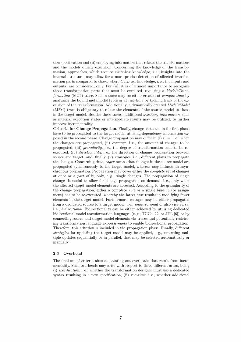
tion specification and (ii) employing information that relates the transformationsand the models during execution. Concerning the knowledge of the transfor-mation, approaches, which require white-box knowledge, i. e., insights into theinternal structure, may allow for a more precise detection of affected transfor-mation parts compared to those, where black-box knowledge, i. e., the inputs andoutputs, are considered, only. For (ii), it is of utmost importance to recognizethose transformation parts that must be executed, requiring a Model2Trans-formation (M2T) trace. Such a trace may be either created at compile-time byanalyzing the bound metamodel types or at run-time by keeping track of the ex-ecution of the transformation. Additionally, a dynamically created Model2Model(M2M) trace is obligatory to relate the elements of the source model to thosein the target model. Besides these traces, additional auxiliary information, suchas internal execution states or intermediate results may be utilized, to furtherimprove incrementality.Criteria for Change Propagation. Finally, changes detected in the first phasehave to be propagated to the target model utilizing dependency information ex-posed in the second phase. Change propagation may differ in (i) time, i. e., whenthe changes are propagated, (ii) coverage, i. e., the amount of changes to bepropagated, (iii) granularity, i. e., the degree of transformation code to be re-executed, (iv) directionality, i. e., the direction of change propagation betweensource and target, and, finally, (v) strategies, i. e., different plans to propagatethe changes. Concerning time, eager means that changes in the source model arepropagated synchronously to the target model, whereas lazy induces an asyn-chronous propagation. Propagation may cover either the complete set of changesat once or a part of it, only, e. g., single changes. The propagation of singlechanges is useful to allow for change propagation on demand, i. e., only whenthe affected target model elements are accessed. According to the granularity ofthe change propagation, either a complete rule or a single binding (or assign-ment) has to be re-executed, whereby the latter case results in modifying fewerelements in the target model. Furthermore, changes may be either propagatedfrom a dedicated source to a target model, i. e., unidirectional or also vice versa,i. e., bidirectional. Bidirectionality can be either achieved by utilizing dedicatedbidirectional model transformation languages (e. g., TGGs [22] or JTL [6]) or byconnecting source and target model elements via traces and potentially restrict-ing transformation language expressiveness to enable bidirectional propagation.Therefore, this criterion is included in the propagation phase. Finally, differentstrategies for updating the target model may be applied, e. g., executing mul-tiple updates sequentially or in parallel, that may be selected automatically ormanually.
2.3 Overhead
The final set of criteria aims at pointing out overheads that result from incre-mentality. Such overheads may arise with respect to three different areas, being(i) specification, i. e., whether the transformation designer must use a dedicatedsyntax resulting in a new specification, (ii) run-time, i. e., whether additional
7
run-time is consumed in contrast to batch transformations, and (iii) memory,i. e., whether additional memory is consumed compared to batch transforma-tions.
3 Comparison of Approaches
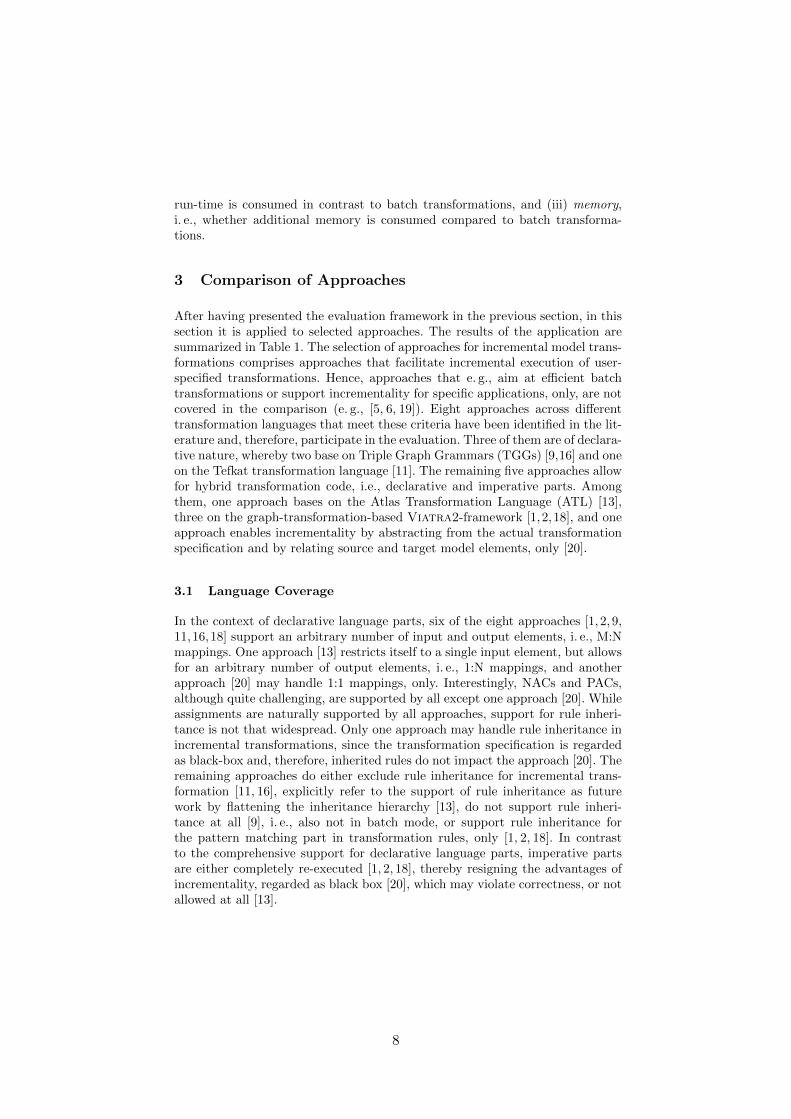
After having presented the evaluation framework in the previous section, in thissection it is applied to selected approaches. The results of the application aresummarized in Table 1. The selection of approaches for incremental model trans-formations comprises approaches that facilitate incremental execution of user-specified transformations. Hence, approaches that e. g., aim at efficient batchtransformations or support incrementality for specific applications, only, are notcovered in the comparison (e. g., [5, 6, 19]). Eight approaches across differenttransformation languages that meet these criteria have been identified in the lit-erature and, therefore, participate in the evaluation. Three of them are of declara-tive nature, whereby two base on Triple Graph Grammars (TGGs) [9,16] and oneon the Tefkat transformation language [11]. The remaining five approaches allowfor hybrid transformation code, i.e., declarative and imperative parts. Amongthem, one approach bases on the Atlas Transformation Language (ATL) [13],three on the graph-transformation-based Viatra2-framework [1,2,18], and oneapproach enables incrementality by abstracting from the actual transformationspecification and by relating source and target model elements, only [20].
3.1 Language Coverage
In the context of declarative language parts, six of the eight approaches [1, 2, 9,11,16,18] support an arbitrary number of input and output elements, i. e., M:Nmappings. One approach [13] restricts itself to a single input element, but allowsfor an arbitrary number of output elements, i. e., 1:N mappings, and anotherapproach [20] may handle 1:1 mappings, only. Interestingly, NACs and PACs,although quite challenging, are supported by all except one approach [20]. Whileassignments are naturally supported by all approaches, support for rule inheri-tance is not that widespread. Only one approach may handle rule inheritance inincremental transformations, since the transformation specification is regardedas black-box and, therefore, inherited rules do not impact the approach [20]. Theremaining approaches do either exclude rule inheritance for incremental trans-formation [11, 16], explicitly refer to the support of rule inheritance as futurework by flattening the inheritance hierarchy [13], do not support rule inheri-tance at all [9], i. e., also not in batch mode, or support rule inheritance forthe pattern matching part in transformation rules, only [1, 2, 18]. In contrastto the comprehensive support for declarative language parts, imperative partsare either completely re-executed [1, 2, 18], thereby resigning the advantages ofincrementality, regarded as black box [20], which may violate correctness, or notallowed at all [13].
8

In summary, one may see that incremental model transformation approachessuffer from restricted language coverage in terms of rule inheritance and imper-ative parts, and thus, not all potential for incremental execution is exploited sofar.
3.2 Execution Phases
Change Detection. Regarding change detection, all approaches detect changesoperation-based and, therefore, comply with source minimality. Atomic changesare supported by all approaches. Concerning composite changes, six approachessupport update operations [1,2,9,13,18,20]. Move operations are explicitly sup-ported by two approaches [2, 9]. Four approaches are able to detect multiplechange operations [2, 9, 16, 18]. However, only one of them actually supports anoptimization of the change log [18]. One approach, although being able to de-tect multiple changes, considers the model difference instead of a change log,and, therefore, eludes the need for change log optimization [16], while for an-other approach the optimization effort is usually higher than the actual propa-gation effort, and, therefore, change log optimization is omitted [9]. Consideringthe granularity of changes, all approaches enable the detection of fine-grainedchanges.
Summing up, current approaches mostly lack the detection of multiple, com-posite change operations and a change log optimization. Support for those cri-teria would favor an optimized change propagation resulting in fewer operationson the target model.
Impact Analysis. Seven of the eight approaches require white-box knowl-edge of the transformation for analyzing rules and generating trace informa-tion [1, 2, 9, 11, 13, 16, 18], while one approach considers the specification of thebatch transformation as a black box [20]. The M2T trace is generated by sevenapproaches [1, 2, 9, 11, 13, 16, 18] at run-time, while two of them generate partsof this trace at compile-time [1, 13]. One approach does not generate any M2Ttrace at all [20], but lacks comprehensive language coverage. All approaches dy-namically generate M2M traces. Concerning auxiliary information, one approachstores the complete transformation context in terms of an SLDNF-tree (SelectiveLinear Definite clause with Negation as Failure) [11], one generates dedicatedrules for change propagation at compile-time [13], and in [2] so-called ChangeHistory Models are used as input for the change propagation. One approach [1]creates database tables for each match pattern in a transformation specificationand employs triggers for change detection, while in [20] a so-called Concept Poolis utilized, which holds similar concepts between source and target models toenable bidirectional change propagation.
In summary, one may see that all approaches require trace information andmost approaches rely on auxiliary information to further leverage incrementality.
Change Propagation. Three approaches propagate changes in an eager man-ner [1, 11, 18]. Four approaches allow for lazy propagation by letting the userdecide when to apply the changes on the target model [2, 9, 13, 16]. Finally,
9

one approach allows for both, synchronous and asynchronous, change propa-gation [20]. The same approach also supports partial propagation. Five of theeight approaches re-execute a complete rule [1,2,9,16,18], while two approachesare capable of re-executing a single binding, only [11, 13]. Those two rely onauxiliary information, being the complete execution context [11] or fine-grainedcompiler-generated rules [13]. One approach does not consider rules or bindingsof the batch transformation specification to be re-executed, since the transfor-mation is regarded as a black-box [20]. Concerning directionality, TGGs supportbidirectionality [9, 16], while other approaches allow for unidirectional changepropagation, only [1,2,11,13,18]. One approach aims at deriving a bidirectionalmodel transformation from a unidirectional transformation specification, but islimited in terms of language coverage [20]. Solely the approaches that build onthe Viatra2-framework offer manual selection of strategies in terms of sequen-tial or parallel execution of change propagation [1, 2, 18].
Summing up, current incremental model transformation approaches mostlypropagate changes synchronously with a predefined strategy. Thereby, situationsthat may require different execution strategies for efficient incremental executionmay not be handled satisfactorily.
3.3 Overhead
Regarding the induced overheads, two of the eight approaches require a new spec-ification by the transformation designer to allow for incremental execution [2,18].Concerning run-time overheads, three approaches state, that even in the worstcase (i. e., the complete source model has been changed) incremental execution isas fast as batch transformation, i. e., no run-time overhead occurs [2,9,16], whilethe remaining approaches lack any statement on this fact. Finally, all approachesaccept memory overheads in terms of traces and auxiliary information.
In summary, one may see that most approaches introduce incrementality bychanges to the execution engine instead of requiring a new syntax for transforma-tion specifications, which is favorable, since then incrementality is transparentto the transformation designer. All approaches induce memory overheads dueto the generation of traces and auxiliary information, which are, nevertheless,essential for incremental execution [12].
4 Lessons Learned
In this section, lessons learned gained from the evaluation and comparison ofapproaches are discussed along the different evaluation categories.Insufficient Support for Imperative Parts. While all examined approachessupport declarative language parts, they lack sufficient support for imperativeparts, which are either disregarded at all or treated as black box, i. e., executedcompletely, instead of breaking them down into fine-grained parts. Consequently,extensive support for imperative parts, e. g., by exploiting incremental evaluationof conditions and bindings [4], may further leverage incrementality.
10

Inse
rt
Del
ete
Upd
ate
Mov
e
Blac
k Bo
x
Whi
te B
ox
Com
pile
-tim
e
Run
-tim
e
dete
rmin
istic
r
example used for evaluation[9] TGG 1..* 1..* n.a. n.a. 1..* 1..* 1..* 1..* - - - - - - - - 1 - - - - - -[16] TGG 1..* 1..* - n.a. 1..* 1..* - - n.a. - - - - - - - 1 - -
[11] Tefkat 1..* 1..* - n.a. 1 1 - - n.a. - - SLDNFtree - - - - 1 - u. - - - - - class2relational
[13] ATL 1 1..* - - 1 1 1 - n.a. - Compiler
Generated Rules
- - - - 1 - u. -- - - - class2relational
[18] VIATRA2 1..* 1..* ~ 1..* 1..* 1..* - - - - - - - - 2 m. - u. - - - ~ -
[2] VIATRA2 1..* 1..* ~ 1..* 1..* 1..* 1..* - - - Change History Models
- - - - 2 m. - -- - -
[1] VIATRA2 1..* 1..* ~ 1 1 1 - n.a. - Database Tables - - - - 2 m. u. -
[20] Arbi-trary 1 1 - - ~ 1 1 1 - n.a. - - - Concept
Pool n.a. n.a. - 1 - u. - - - - - java2wsdl axis trafo
Tratt PMT 1..* 1..* ? 1..* 1..* 1..* - - - - - - - - 2 m. - ? -Hass QVT 1 1 - - n.a. n.a. (1) 1 1 n.a. - KB - - n.a. n.a. - 1 - - -
3
Giese2009 TGG, Fuj ?
-
1 1 1 - - - - - - - - - - - - sld blocks to class diagram
8 Varr graph trafo ? ? ? ? ? ? - - - - - incr. graph transformations
7 RazaQVT-OM - - - - - - - books2libr efficient batch trafos, not incr.
8 Tisi2ATL *-
- - - - - - class2relat lazy transformations
9 Song
QVT-Relational, mediniQVT - spec. incr. engine for runtime models
10 VogeTGG, runtime monitoring? based on Giese2006/2009
11
Johann2004
IBM Rational Rose framework for incr. transformations of models
12 Cicc hybrid multi-view modelling hybrid multi-view modelling13 Emo future work
Model 2
Trans-form.
Req. Know-
ledge of Transfor-mation Specifi-cation
No
Mem
ory
Ove
rhea
d
Over-head
Assi
gnm
ent
Rul
e In
herit
ance
Cha
nge
Log
Opt
imiz
atio
n
Auxi
liary
Info
rmat
ion
Live
Tra
nsfo
rmat
ion
Revi
sions
of T
arge
t Mod
el
Diff
eren
t Exe
cutio
n St
rate
giesDirec-
tion
Conf
lict R
esol
utio
n
Change Propagation
Time Granu-larity
Parti
alC
ompl
ete
Num
ber
Sele
ctio
n
Uni
dire
ctio
nal
No
Spec
ifica
tion
Ove
rhea
dN
o R
un-ti
me
Ove
rhea
d
Impact AnalysisExecution Phases
Change DetectionStrat-egy
Bind
ing
Eage
r (Sy
nchr
onou
s)
Cover-age
Lazy
(Asy
nchr
onou
s)
Rul
e
Bidi
rect
iona
l
Link
Granu-larity
Obj
ect
Valu
e
Mod
el2M
odel
Trace
Hybr
id (D
ecl.
+ Im
p.)
Type & Number
Atomic Com-posite
Decl
arat
ive
Lang
uage
/ Fr
amew
ork
Sour
ce M
inim
ality
Appr
oach
Condi-tions
Language CoverageDeclarative Parts
Impe
rativ
e Pa
rts
Num
ber o
f Inp
ut E
lem
ents
Num
ber o
f Out
put E
lem
ents
NAC
sPA
Cs
propagation granularity: + filter, + imperative teile wie unterscheiden sich ansätze? was können sie NICHT? (siehe outlook und conclusion von versch. paper) einschränkungen der ansätze in tabelle aufnehmen
Legend: ... supported - ... not supported ~ ... partially supported * ... multiple n.a. ... not applicable m. ... manual u. ... unknown
Table 1. Comparison Table of Incremental Model Transformation Approaches
Focus on Basic Change Operations. Atomic change operations are sup-ported by all approaches. However, support for composite change operations,such as update and move, is not that widespread, but would allow for a moreefficient change propagation by utilizing according change propagation opera-tions.
Trace Information is Mandatory. All approaches rely on trace information.Furthermore, the more trace information is generated to relate elements of sourceand target models as well as model elements and the transformation specification,the more accurateness in change propagation may be achieved. Of course, thisis the general trade-off between space and time in computing.
Lack of Appropriate Propagation Strategies. Current incremental modeltransformation approaches do not provide different propagation strategies ac-cording to a given change situation. In case of many changes, re-execution of abatch transformation may outperform the run-time performance of incrementalexecution in certain cases. An automatic selection of an appropriate propaga-tion strategy could be achieved by analyzing the changes, the transformationspecification, and the traces.
Lack of Proof of Correctness. Apart from one approach [16], correctnessof the incremental model transformation approaches is not proven. Thus, for-mal proofs for correctness would be highly beneficial for the confidence of theincremental transformations.
11

5 Conclusion
In this paper, we presented a survey on incremental model transformation ap-proaches. Therefore, criteria for evaluating and comparing incremental modeltransformation approaches have been proposed. Eight recent approaches havebeen compared according to the criteria and lessons learned have been presented.
Summing up, although several approaches for incremental model transfor-mations exist, there is still space for improvements including (i) better supportfor imperative language parts, (ii) more efficient change propagation with ded-icated change operators, (iii) provision and automatic selection of appropriatepropagation strategies, and (iv) proving correctness of incremental model trans-formations.
Acknowledgements
We would like to thank Stephan Hildebrandt, Marius Lauder, Anthony Anjorin,Ali Razavi, Istvan Rath, Gabor Bergmann, Salvador Martınez Perez, and Mas-simo Tisi for their helpful comments on the paper.
This work has been funded by the Austrian Federal Ministry for Transport,Innovation and Technology (bmvit) under grant ffg bridge 832160 and ffgfit-it 825070 and 829598, ffg Basisprogramm 838181, and by oad under grantAR18/2013 and UA07/2013.
References
1. Bergmann, G., Horvath, D., Horvath, A.: Applying Incremental Graph Transfor-mation to Existing Models in Relational Databases. In: 6th Int. Conf. on GraphTransformations. Springer (2012)
2. Bergmann, G., Rath, I., Varro, G., Varro, D.: Change-driven model transforma-tions. SoSym 11(3) (Jul 2012)
3. Bezivin, J.: On the Unification Power of Models. SoSym 4(2) (May 2005)4. Cabot, J., Teniente, E.: Incremental Evaluation of OCL Constraints. In: 18th Int.
Conf. on Advanced Information Systems Engineering. Springer (2006)5. Cicchetti, A., Ciccozzi, F., Leveque, T.: Supporting Incremental Synchronization
in Hybrid Multi-view Modelling. In: Int. Conf. on Models in SE. Springer (2012)6. Cicchetti, A., Di Ruscio, D., Eramo, R., Pierantonio, A.: JTL: A Bidirectional
and Change Propagating Transformation Language. In: Int. Conf. on SoftwareLanguage Engineering. Springer (2011)
7. Conradi, R., Westfechtel, B.: Version Models for Software Configuration Manage-ment. ACM Comp. Surv. 30(2) (Jun 1998)
8. Czarnecki, K., Helsen, S.: Feature-Based Survey of Model Transformation Ap-proaches. IBM Systems Journal 45(3) (Jul 2006)
9. Giese, H., Hildebrandt, S., Neumann, S.: Model Synchronization at Work: KeepingSysML and AUTOSAR Models Consistent. In: Graph Transformations and Model-Driven Engineering. LNCS, vol. 5765. Springer (2010)
10. Gupta, A., Mumick, I.S.: Maintenance of Materialized Views: Problems, Tech-niques, and Applications. IEEE Data Eng. Bull. 18(2) (1995)
12

11. Hearnden, D., Lawley, M., Raymond, K.: Incremental Model Transformation forthe Evolution of Model-Driven Systems. In: 9th Int. Conf. on Model Driven Engi-neering Languages and Systems. Springer (2006)
12. Johann, S., Egyed, A.: Instant and Incremental Transformation of Models. In: 19thInt. Conf. on Automated Software Engineering. IEEE (2004)
13. Jouault, F., Tisi, M.: Towards Incremental Execution of ATL Transformations. In:3rd Int. Conf. on Theory and Practice of Model Transformations. Springer (2010)
14. Kappel, G., Langer, P., Retschitzegger, W., Schwinger, W., Wimmer, M.: ModelTransformation By-Example: A Survey of the First Wave. In: Conceptual Mod-elling and Its Theoretical Foundations. Springer (2012)
15. Kolovos, D., Paige, R.F., Polack, F.A.: The Grand Challenge of Scalability forModel Driven Engineering. In: Models in SE. Springer (2009)
16. Lauder, M., Anjorin, A., Varro, G., Schurr, A.: Efficient Model Synchronizationwith Precedence Triple Graph Grammars. In: 6th Int. Conf. on Graph Transfor-mations. Springer (2012)
17. Mens, T., Van Gorp, P.: A Taxonomy of Model Transformation. ENTCS 152 (Mar2006)
18. Rath, I., Bergmann, G., Okros, A., Varro, D.: Live Model Transformations Drivenby Incremental Pattern Matching. In: 1st Int. Conf. on Theory and Practice ofModel Transformations. Springer (2008)
19. Razavi, A., Kontogiannis, K.: Partial Evaluation of Model Transformations. In:Proc. of the 2012 Int. Conf. on Software Engineering. IEEE Press (2012)
20. Razavi, A., Kontogiannis, K., Brealey, C., Nigul, L.: Incremental Model Synchro-nization in Model Driven Development Environments. In: Conf. of the Center f.Adv. Studies on Collab. Research. IBM (2009)
21. Scheidgen, M., Zubow, A., Fischer, J., Kolbe, T.H.: Automated and TransparentModel Fragmentation for Persisting Large Models. In: 15th Int. Conf. on ModelDriven Engineering Languages and Systems. Springer (2012)
22. Schurr, A.: Specification of Graph Translators with Triple Graph Grammars. In:Graph-Theoretic Concepts in Computer Science. Springer Berlin Heidelberg (1995)
23. Wimmer, M., Kappel, G., Kusel, A., Retschitzegger, W., Schonbock, J., Schwinger,W., Kolovos, D., Paige, R., Lauder, M., Schurr, A., Wagelaar, D.: Surveying RuleInheritance in Model-to-Model Transformation Languages. Journal of Obj. Techn.11(2) (Aug 2012)
24. Wimmer, M., Schauerhuber, A., Kappel, G., Retschitzegger, W., Schwinger, W.,Kapsammer, E.: A Survey on UML-Based Aspect-Oriented Design Modeling. ACMComp. Surv. 43(4) (Oct 2011)
13

Co-evolution of Metamodels and Modelsthrough Consistent Change Propagation
Andreas Demuth, Roberto E. Lopez-Herrejon, and Alexander Egyed
Institute for Systems Engineering and AutomationJohannes Kepler University (JKU)
Linz, Austria{andreas.demuth|roberto.lopez|alexander.egyed}@jku.at
Abstract. In Model-Driven Engineering (MDE), metamodels anddomain-specific languages are key artifacts as they are used to define syn-tax and semantics of domain models. However, metamodels are evolvingover time, requiring existing domain models to be co-evolved. Thoughapproaches have been proposed for performing such co-evolution auto-matically, those approaches typically support only specific metamodelchanges. In this paper, we present a vision of co-evolution betweenmetamodels and models through consistent change propagation. The ap-proach addressed co-evolution issues without being limited to specificmetamodels or evolution scenarios. It relies on incremental managementof metamodel-based constraints that are used to detect co-evolution fail-ures (i.e., inconsistencies between metamodel and model). After failuredetection, the approach automatically generates suggestions for correc-tion (i.e., repairs for inconsistencies). Preliminary validation results arepromising as they indicate that the approach computes correct sugges-tions for model adaptations, and that it scales and can be applied livewithout interrupting tool users.
1 Introduction
In Model-Driven Development (MDD) [1], metamodels are key artifacts that rep-resent real-world domains. Therefore, they define the language of models; that is,the different elements available for modeling along with their interdependencies.Metamodels thus impose structural and semantical constraints on models [2].Although metamodels are often perceived as static artifacts that do not change,it has been shown that the opposite is the case: metamodels do evolve over timefor various reasons. For instance, there is a trend for flexible design tools withadaptable metamodels that can be tailored to different domains (e.g., [3]). An-other common source for metamodel evolution are refactorings that focus onimproving a metamodel’s structure and usability.
Co-evolution of models denotes the process of adapting models as a conse-quence of metamodel evolution [4, 5]. This is a non trivial process, and incor-rect co-evolution may cause models to no longer comply with their metamod-els. Several incremental approaches have been proposed to support this pro-cess (e.g., [6]). Unfortunately, proposed solutions are typically limited to specific
14
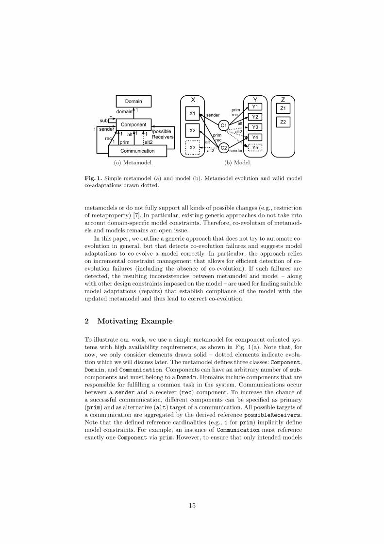
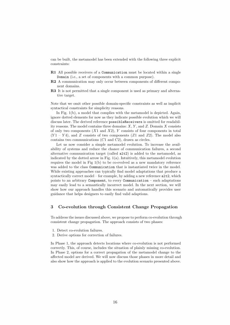
(a) Metamodel. (b) Model.
Fig. 1. Simple metamodel (a) and model (b). Metamodel evolution and valid modelco-adaptations drawn dotted.
metamodels or do not fully support all kinds of possible changes (e.g., restrictionof metaproperty) [7]. In particular, existing generic approaches do not take intoaccount domain-specific model constraints. Therefore, co-evolution of metamod-els and models remains an open issue.
In this paper, we outline a generic approach that does not try to automate co-evolution in general, but that detects co-evolution failures and suggests modeladaptations to co-evolve a model correctly. In particular, the approach relieson incremental constraint management that allows for efficient detection of co-evolution failures (including the absence of co-evolution). If such failures aredetected, the resulting inconsistencies between metamodel and model – alongwith other design constraints imposed on the model – are used for finding suitablemodel adaptations (repairs) that establish compliance of the model with theupdated metamodel and thus lead to correct co-evolution.
2 Motivating Example
To illustrate our work, we use a simple metamodel for component-oriented sys-tems with high availability requirements, as shown in Fig. 1(a). Note that, fornow, we only consider elements drawn solid – dotted elements indicate evolu-tion which we will discuss later. The metamodel defines three classes: Component,Domain, and Communication. Components can have an arbitrary number of sub-components and must belong to a Domain. Domains include components that areresponsible for fulfilling a common task in the system. Communications occurbetween a sender and a receiver (rec) component. To increase the chance ofa successful communication, different components can be specified as primary(prim) and as alternative (alt) target of a communication. All possible targets ofa communication are aggregated by the derived reference possibleReceivers.Note that the defined reference cardinalities (e.g., 1 for prim) implicitly definemodel constraints. For example, an instance of Communication must referenceexactly one Component via prim. However, to ensure that only intended models
15
can be built, the metamodel has been extended with the following three explicitconstraints:
R1 All possible receivers of a Communication must be located within a singleDomain (i.e., a set of components with a common purpose).
R2 A communication may only occur between components of different compo-nent domains.
R3 It is not permitted that a single component is used as primary and alterna-tive target.
Note that we omit other possible domain-specific constraints as well as implicitsyntactical constraints for simplicity reasons.
In Fig. 1(b), a model that complies with the metamodel is depicted. Again,ignore dotted elements for now as they indicate possible evolution which we willdiscuss later. The derived reference possibleReceivers is omitted for readabil-ity reasons. The model contains three domains: X, Y , and Z. Domain X consistsof only two components (X1 and X2), Y consists of four components in total(Y 1 – Y 4), and Z consists of two components (Z1 and Z2). The model alsocontains two communications (C1 and C2), drawn as circles.
Let us now consider a simple metamodel evolution. To increase the avail-ability of systems and reduce the chance of communication failures, a secondalternative communication target (called alt2) is added to the metamodel, asindicated by the dotted arrow in Fig. 1(a). Intuitively, this metamodel evolutionrequires the model in Fig 1(b) to be co-evolved as a new mandatory referencewas added to the class Communication that is instantiated twice in the model.While existing approaches can typically find model adaptations that produce asyntactically correct model – for example, by adding a new reference alt2, whichpoints to an arbitrary Component, to every Communication – such adaptationsmay easily lead to a semantically incorrect model. In the next section, we willshow how our approach handles this scenario and automatically provides userguidance that helps designers to easily find valid adaptions.
3 Co-evolution through Consistent Change Propagation
To address the issues discussed above, we propose to perform co-evolution throughconsistent change propagation. The approach consists of two phases:
1. Detect co-evolution failures.
2. Derive options for correction of failures.
In Phase 1, the approach detects locations where co-evolution is not performedcorrectly. This, of course, includes the situation of plainly missing co-evolution.In Phase 2, options for a correct propagation of the metamodel change to theaffected model are derived. We will now discuss those phases in more detail andalso show how the approach is applied to the evolution scenario presented above.
16
3.1 Phase 1: Co-evolution Failure Detection
Although metamodel evolution is likely to require model adaptations, this isnot a necessity – a metamodel may also change in ways that do not affect thevalidity of existing models. For example, when an optional reference is added.Additionally, models may be changed manually by designers or automaticallyby tools after a metamodel evolution occurred, trying to co-evolve the model.Therefore, it is necessary after a metamodel change – and subsequent modeladaptations – to determine whether an affected model is consistent with theupdated metamodel. If it is, co-evolution was performed correctly and no furtherintervention is required. If, however, the model is inconsistent with the updatedmetamodel, co-evolution failed and additional model adaptations are necessary.
Constraint Management As we have shown in the running example, con-straints can be used for ensuring both syntax and semantics. Therefore, whenthe metamodel evolves, constraints of both kinds may be affected. By usingan incremental constraint management approach, it is possible to update con-straints after metamodel changes – ensuring that models are always validatedwith constraints that are up-to-date.
In our example, the addition of alt2 in Fig. 1(a) requires a new syntacticalconstraint to be enforced on models:
R4 Each Communication must reference a Component via alt2.
Consistency Checking After updating the set of constraints imposed by themetamodel, standard consistency checkings mechanisms (e.g., [8, 9]) can be usedto detect inconsistencies. While the typical scenario is that an unchanged modelbecomes inconsistent after metamodel evolution, it is also possible that a pre-viously inconsistent model becomes consistent without any adaptations. Addi-tionally, model adaptations that are performed for the purpose of co-evolutionmay be incorrect and actually introduce new inconsistencies. If a consistencychecker that uses an up-to-date set of constraints detects inconsistencies after ametamodel evolution, model adaptations are required and co-evolution was notdone correctly.
After adding the new syntactical constraint defined above, any standardconsistency checker will find that the model in Fig. 1(b) contains two incon-sistencies: neither C1 nor C2 provide a second alternative target. Thus, ourintuitive assumption that additional model adaptations are necessary for correctco-evolution has been confirmed.
3.2 Phase 2: Co-evolution Correction
Once co-evolution failures have been detected, our approach reaches Phase 2 inwhich those failures are corrected.
17

Repair Options To correct co-evolution failures and propagate the metamodelchange correctly, it is necessary to find model adaptations (i.e., repair options)that transform the inconsistent model into a consistent one. Unfortunately, find-ing suitable adaptations is non trivial as every change to a model may not onlyeliminate the violation of a constraint, but it may also cause other constraintsto be violated. However, single changes can of course also remove several in-consistencies at once. Due to those side effects, finding suitable corrections is acomplex task that should not be performed in an ad-hoc manner. Our approachemploys a reasoning mechanism that takes into consideration all design con-straints present in a model to find suitable adaptations [10]. Note that using notonly those constraints that are actually based on the metamodel but all designconstraints, repairs can be computed with higher precision as more informationis available for the reasoning engine and side effects can be computed.
Let us come back to our example. During Phase 1, two inconsistencies causedby the elements C1 and C2 were detected in the model. First, we consider theinconsistency involving C1. To correct the syntax and remove the violation ofconstraint R4, a reference alt2 to any component is sufficient. Moreover, in eachdomain a new component could be created and used as second alternative targetfor C1. Of course, it would also be possible to create a new component in anentirely new domain. Therefore, there are 12 options available in total: one foreach of the eight existing (i.e., solid drawn) components in Fig. 1(b), one foreach of the three domains, and one for a new domain with a new component.However, by also taking into account the domain-specific constraints R1 – R3from Section 2, our approach computes side effects for each of those options. Dueto constraint R2, adding either X1 or X2 as second alternative target to C1 is nota valid adaptation as this would violate R2. Additionally, the existing referencesprim and alt from C1 to components of domain Y disallow the use of anycomponents that belong to a domain other than Y , according to constraint R1.This rules out any remaining options that involve a second alternative receiver indomain Z or in a newly created domain. Finally, constraint R3 disallows Y 1 andY 2 as options because they are already possible receivers. Note that this means areduction from 12 options – from which 9 are actually semantically incorrect – toonly 3 options that co-evolve C1 correctly. Those are drawn dotted in Fig. 1(b).
For the communication C2, the constraints R1 – R4 can only be satisfiedby adding a new component to domain X that is used as second alternativereceiver, as indicated by the dotted drawn component X3 in Fig. 1(b).
Change Execution Although each derived repair option fixes a model, someof them may seem more intuitive and more logical to stakeholders than others.Therefore, stakeholders should choose manually which of the available repairoptions should be executed. However, repair options could of course be selectedand executed automatically if model characteristics such as readability are oflow importance.
In our example, the co-evolution of C2 can be done automatically as there isonly one repair option. To repair the inconsistency of C1, a user has to decide
18
between only three options that propagate the metamodel change correctly tothe model.
4 Discussion
Let us now briefly discuss the planned implementation of our approach andpreliminary validation results.
4.1 Prototype Implementation
The individual parts of the approach have been implemented in previous work.For the constraint management part, we have implemented a template-basedtransformation engine that generates and updates metamodel-based model con-straints [11]. For the consistency checking, we rely on the Model/Analyzer con-sistency checking framework [12] that allows for efficient incremental additionand removal of models constraints. Finally, for the repair option generation, wehave implemented a generic inconsistency repair mechanism that builds uponthe Model/Analyzer framework [10].
4.2 Preliminary Performance Results
We have demonstrated in [13] that constraint management through transfor-mation is efficient and that constraints are updated within milliseconds after ametamodel change. In [12] and [9], we have shown that the Model/Analyzer is ca-pable of validating constraints instantly, even for large industrial models of over100,000 model elements. Moreover, it was demonstrated that adding constraints(or removing them) is handled efficiently. For repairing detected inconsistencies,we have observed that for typical UML models less than 10 suggestions were de-rived, also within milliseconds [10]. Moreover, we have previously found that byconsidering side-effects between different constraints, the number of suggestionscan be reduced even further [14].
4.3 Applicability
We have illustrated how our approach updates constraints and derives options forcorrecting co-evolution failures. Although we have used the proposed solution inisolation to keep the example simple and focused, it is compatible with existingautomatic co-evolution techniques. When used in isolation, our approach detectsthe absence of necessary model adaptations as co-evolution failures. When com-bined with other approaches, it also detects co-evolution failures that are basedon incorrect model adaptations. Therefore, our solution is not a substitute buta complement to existing technologies.
19

5 Related Work
Let us now discuss how the presented approach relates to other work that hasbeen done in the field of co-evolving metamodels and models. The necessityof support for efficient and automatic co-evolution of metamodel and modelswas identified as a major challenge in software evolution by Mens et al. [4],and various approaches have been published to address it. Instead of seeing ametamodel evolution step as a single, complex, and manually performed changethat is performed in an ad-hoc manner, Wachsmuth [15] describes metamodelevolution as a series of transformational adaptations performed stepwise. Meta-model changes are traced and qualified based on properties such as semantics-or instance-preservation. Co-transformations for models can be generated basedon transformation patterns that are instantiated with the performed metamodeltransformations. Cicchetti et al. [16] similarly classify metamodel and modelchanges. They identified dependencies between different kinds of modificationsand propose an automated approach that leverages these dependencies for per-forming co-evolution automatically. Herrmannsdoerfer et al. [17] investigated towhich degree different metamodel adaptations can be handled automatically.Note that those approaches focus on decomposing metamodel adaptations intoatomic steps that are used for finding suitable co-adaptations of models. Whileour approach also relies on atomic metamodel modifications, we use those mod-ifications for updating the conditions that must hold in a valid model. Ourapproach in general does not try to automate co-evolution of metamodels andmodels. Instead, the fully automated co-evolution of metamodels and constraintsallows our reasoning engine to provide tool users with specific guidance on howco-evolution can be performed. Note, however, that in some cases models mayalso be adapted automatically (e.g., if only a single repair option exists).
Wimmer et al. [18] merge different metamodel versions to a unified meta-model and then apply co-evolution rules to models. New metaclasses are instan-tiated and existing model elements that are no longer required are removed. Dueto issues regarding typecasts and instantiation, their co-evolution rules had tobe adapted. The components used in our prototype implementation are capableof handling arbitrary metamodel adaptations, including type changes.
6 Conclusion and Future Work
In this vision paper, we have presented the outline of a novel approach for sup-porting the co-evolution of metamodels and models. Our approach is generic andrelies on the detection of inconsistencies that occur after metamodel evolution.Those inconsistencies serve as input for a reasoning mechanism that provides asoutput a set of possible model adaptations for repairing – that is, co-evolving –an affected model.
The preliminary validation results are promising and suggest that the pre-sented approach is feasible and that it can be implemented efficiently. However,these were observed in tests that were performed with prototype implementa-tions for the individual components involved in the approach. For a complete
20
validation, we have yet to conduct case studies with industrial models and acomplete implementation that fully integrates the prototypes of individual com-ponents.
References
1. D. C. Schmidt, “Guest editor’s introduction: Model-driven engineering,” IEEEComputer, vol. 39, no. 2, pp. 25–31, 2006.
2. R. B. France and B. Rumpe, “Model-driven development of complex software: Aresearch roadmap,” in FOSE, pp. 37–54, 2007.
3. E.-J. Manders, G. Biswas, N. Mahadevan, and G. Karsai, “Component-orientedmodeling of hybrid dynamic systems using the generic modeling environment,” inMBD/MOMPES, pp. 159–168, 2006.
4. T. Mens, M. Wermelinger, S. Ducasse, S. Demeyer, R. Hirschfeld, and M. Jazayeri,“Challenges in software evolution,” in IWPSE, pp. 13–22, 2005.
5. L. M. Rose, D. S. Kolovos, R. F. Paige, and F. A. C. Polack, “Enhanced automationfor managing model and metamodel inconsistency,” in ASE, pp. 545–549, 2009.
6. M. Herrmannsdoerfer, S. Benz, and E. Jurgens, “COPE - automating coupledevolution of metamodels and models,” in ECOOP, pp. 52–76, 2009.
7. A. Cicchetti, D. Di Ruscio, R. Eramo, and A. Pierantonio, “Automating co-evolution in model-driven engineering,” in EDOC, pp. 222–231, 2008.
8. C. Nentwich, L. Capra, W. Emmerich, and A. Finkelstein, “xlinkit: a consistencychecking and smart link generation service,” ACM Trans. Internet Techn., vol. 2,no. 2, pp. 151–185, 2002.
9. I. Groher, A. Reder, and A. Egyed, “Incremental consistency checking of dynamicconstraints,” in FASE, pp. 203–217, 2010.
10. A. Reder and A. Egyed, “Computing repair trees for resolving inconsistencies indesign models,” in ASE, pp. 220–229, 2012.
11. A. Demuth, R. E. Lopez-Herrejon, and A. Egyed, “Supporting the co-evolutionof metamodels and constraints through incremental constraint management,” inMoDELS, 2013. Accepted for publication.
12. A. Reder and A. Egyed, “Model/analyzer: a tool for detecting, visualizing andfixing design errors in UML,” in ASE, pp. 347–348, 2010.
13. A. Demuth, R. E. Lopez-Herrejon, and A. Egyed, “Constraint-driven mod-eling through transformation,” Software and System Modeling, 2013. DOI:10.1007/s10270-013-0363-3.
14. A. Nohrer, A. Reder, and A. Egyed, “Positive effects of utilizing relationshipsbetween inconsistencies for more effective inconsistency resolution: NIER track,”in ICSE, pp. 864–867, 2011.
15. G. Wachsmuth, “Metamodel adaptation and model co-adaptation,” in ECOOP,pp. 600–624, 2007.
16. A. Cicchetti, D. D. Ruscio, and A. Pierantonio, “Managing dependent changes incoupled evolution,” in ICMT, pp. 35–51, 2009.
17. M. Herrmannsdoerfer, S. Benz, and E. Jurgens, “Automatability of coupled evo-lution of metamodels and models in practice,” in MoDELS, pp. 645–659, 2008.
18. M. Wimmer, A. Kusel, J. Schonbock, W. Retschitzegger, W. Schwinger, andG. Kappel, “On using inplace transformations for model co-evolution,” in MtATL,INRIA & Ecole des Mines de Nantes, 2010.
21
Automating Instance Migration in Response toOntology Evolution
Mark Fischer1, Juergen Dingel1, Maged Elaasar2, Steven Shaw3
1Queen’s University, {fischer,dingel}@cs.queensu.ca2Carleton University, [email protected]
3IBM, [email protected]
Abstract
Of great importance to the efficient use of an ontology is the abilityto easily effect change [9]. This paper presents an approach toward au-tomating a method for instance data to be kept up to date as an ontologyevolves.
1 Introduction and MotivationAs computers become more ubiquitous and the information they attain andstore becomes vast, the benefit gained from formally representing that infor-mation grows. Ontologies are one of the key technologies which strive to giveinformation well-defined meaning. This, in turn, allows computers and peopleto work more cooperatively [10].
While there are many applications which help develop and create ontologies,there are still very few which aid or facilitate the evolution of an ontology [7].Changes in domain understanding and changes in application requirements oftennecessitate a change in the underlying ontology [11]. It may be impracticalor impossible to predict how or even if an ontology may change after beingdeployed. Changes to an ontology may generate inconsistencies in dependentontologies. As ontologies evolve and grow, it becomes increasingly attractive tofind efficient ways of keeping dependent information up to date.
A change in an ontology requiring dependent ontologies to be updated is acommon problem. IBM’s Design Manager is a collaborative design managementsoftware. It works with domains which are specified using ontologies to store,share, search and manage designs and models. The work presented in this paperwas inspired, in part, by work IBM has done and problems IBM has encounteredwhile developing Design Manager. Figure 1 helps describe the problem beingaddressed.
In Figure 1, there exists an original ontology (O), an evolved or updatedontology (O′) and a set of dependent ontologies (I1, I2, ..., In). For all j, Ij
1
22
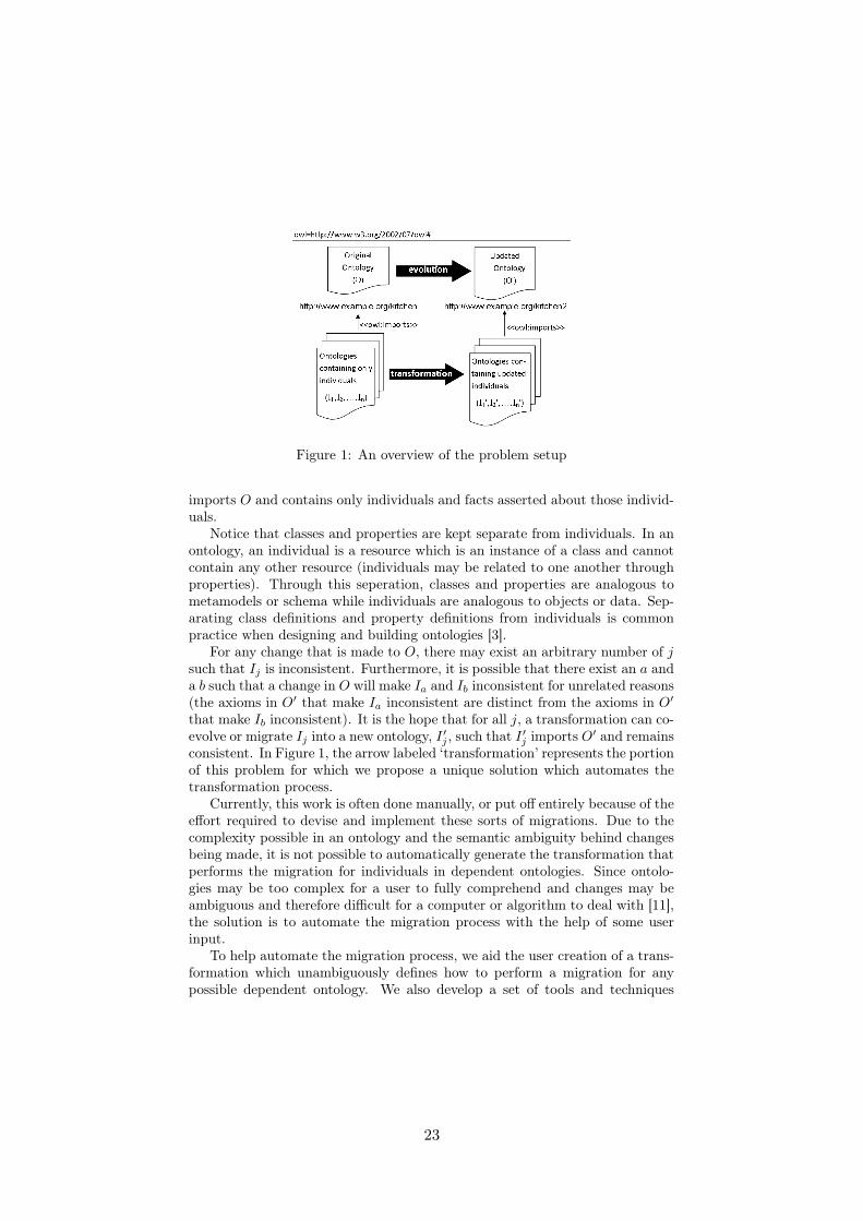
Figure 1: An overview of the problem setup
imports O and contains only individuals and facts asserted about those individ-uals.
Notice that classes and properties are kept separate from individuals. In anontology, an individual is a resource which is an instance of a class and cannotcontain any other resource (individuals may be related to one another throughproperties). Through this seperation, classes and properties are analogous tometamodels or schema while individuals are analogous to objects or data. Sep-arating class definitions and property definitions from individuals is commonpractice when designing and building ontologies [3].
For any change that is made to O, there may exist an arbitrary number of jsuch that Ij is inconsistent. Furthermore, it is possible that there exist an a anda b such that a change in O will make Ia and Ib inconsistent for unrelated reasons(the axioms in O′ that make Ia inconsistent are distinct from the axioms in O′
that make Ib inconsistent). It is the hope that for all j, a transformation can co-evolve or migrate Ij into a new ontology, I ′j , such that I ′j imports O′ and remainsconsistent. In Figure 1, the arrow labeled ‘transformation’ represents the portionof this problem for which we propose a unique solution which automates thetransformation process.
Currently, this work is often done manually, or put off entirely because of theeffort required to devise and implement these sorts of migrations. Due to thecomplexity possible in an ontology and the semantic ambiguity behind changesbeing made, it is not possible to automatically generate the transformation thatperforms the migration for individuals in dependent ontologies. Since ontolo-gies may be too complex for a user to fully comprehend and changes may beambiguous and therefore difficult for a computer or algorithm to deal with [11],the solution is to automate the migration process with the help of some userinput.
To help automate the migration process, we aid the user creation of a trans-formation which unambiguously defines how to perform a migration for anypossible dependent ontology. We also develop a set of tools and techniques
2
23
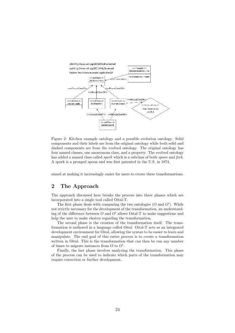
Figure 2: Kitchen example ontology and a possible evolution ontology. Solidcomponents and their labels are from the original ontology while both solid anddashed components are from the evolved ontology. The original ontology hasfour named classes, one anonymous class, and a property. The evolved ontologyhas added a named class called spork which is a subclass of both spoon and fork.A spork is a pronged spoon and was first patented in the U.S. in 1874.
aimed at making it increasingly easier for users to create these transformations.
2 The ApproachThe approach discussed here breaks the process into three phases which areincorporated into a single tool called Oital-T.
The first phase deals with comparing the two ontologies (O and O′). Whilenot strictly necessary for the development of the transformation, an understand-ing of the difference between O and O′ allows Oital-T to make suggestions andhelp the user to make choices regarding the transformation.
The second phase is the creation of the transformation itself. The trans-formation is authored in a language called Oital. Oital-T acts as an integrateddevelopment environment for Oital, allowing the syntax to be easier to learn andmanipulate. The end goal of this entire process is to create a transformationwritten in Oital. This is the transformation that can then be run any numberof times to migrate instances from O to O′.
Finally, the last phase involves analyzing the transformation. This phaseof the process can be used to indicate which parts of the transformation mayrequire correction or further development.
3
24

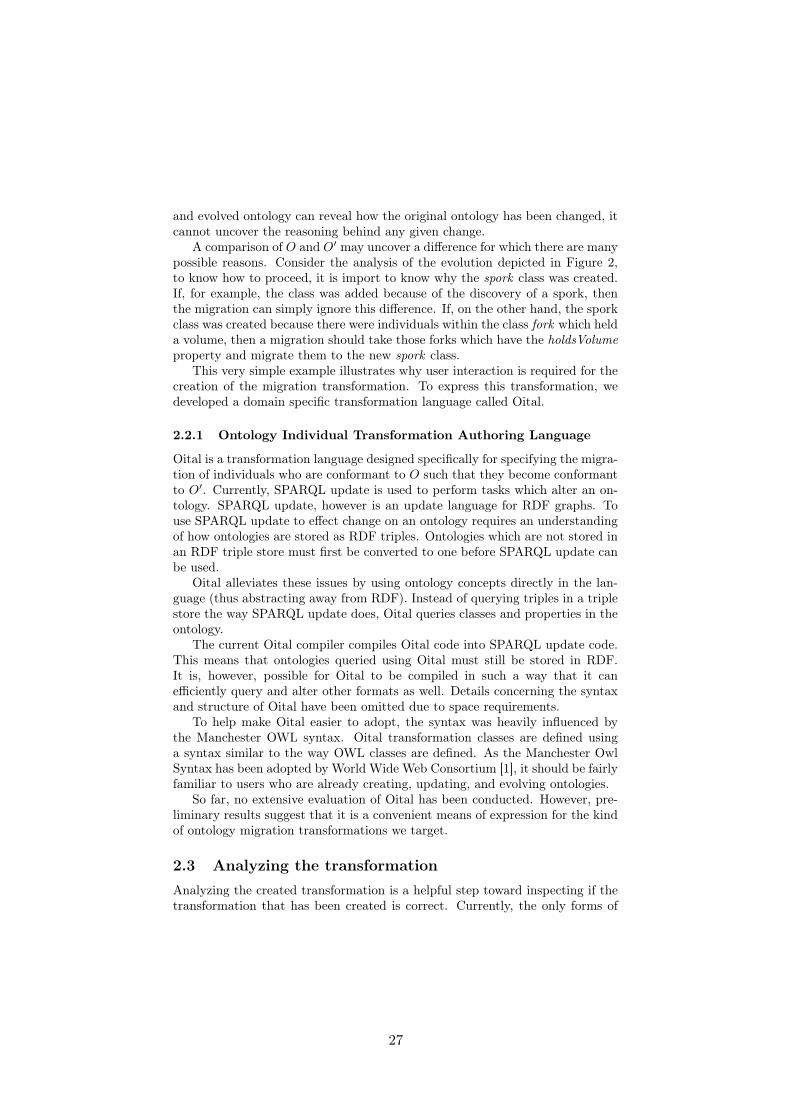
Figure 3: Venn Diagram showing regions where an axiom may be found
2.1 Analyzing the ontologiesIn OWL, the separation of class and properties from individuals is expressedusing axioms and facts. In relation to Figure 1, I1 through In are all a series offacts with an inclusion reference to O while O and O′ both consist of a series ofaxioms (possibly with inclusion references to other ontologies).
Axioms may either restrict or add to an ontology. Restrictive axioms addfurther clarification to the information encoded in an ontology (such as holdsVol-ume exactly 1 in Figure 2) while additive axioms broaden the scope of theinformation (such as the creation of a new class).
Figure 3 depicts three regions in which an axiom may exist. Region 1 de-scribes axioms which can be found in O and not in O′ (deleted axioms), region2 describes those axioms which can be found in both O and O′ (unchangedaxioms), and region 3 describes axioms which can not be found in O but can befound in O′ (new or added axioms).
Axioms may influence one another. In Figure 2, the kitchen ontology has anaxiom (A) stating that cutlery is the domain of the property holdsVolume. Italso has the axiom (B) that there is a specific anonymous restriction class whichcontains only individuals that hold exactly one amount of volume. Axiom B isinfluenced by axiom A because a change in A is axiomatically a change in B aswell. For any axiom, C, the axiom and all other axioms it is influenced by isdenoted as C∗ and called that axiom’s context.
Table 1 gives an overview of how axioms are labeled while analyzing O andO′. If there exists axiom A such that its context, A∗, is entirely in Region 3, thenA cannot be the cause of any inconsistencies. Specifically, if Ij is consistent withrespect to O, then any inconsistencies Ij has with respect to O′ cannot be dueto axiom A. This means that aspects of the updated or evolved ontology whichare entirely unique to the updated ontology are not of concern for the creationof a transformation. Similarly, for any A such that A∗ is entirely in region 2, Acannot cause inconsistencies. This means that those parts of the original andupdated ontologies which remain unchanged are not of concern either.
Axioms found in Region 1 may not, by default, be ignored. If the axiomis restrictive, such as the restriction class in Figure 2, then its removal cannotcreate an inconsistency and is considered OK. If, however, the axiom is additive,then its removal may create inconsistencies. For example, removing the fork isa subclass of cutlery axiom from the kitchen ontology in Figure 2 would result in
4
25

Restrictive Axiom (andits context)
Additive Axiom (andits context)
Region 1 OK Must InvestigateRegion 2 OK OKRegion 3 OK OK
Region 1 & 2 Should Investigate Must InvestigateRegion 2 & 3 Must Investigate Should Investigate
Table 1: Overview of which axioms require further investigation with respectto specific regions as outlined in Figure 3. OK means the axiom may be safelyignored as it is very unlikely to hinder a migration. Should Investigate meansthis axiom is unlikely to hinder migration, but it is probably semantically im-portant. Must Investigate means this axiom needs to be considered carefullyduring migration as it may cause inconsistencies.
any facts which state that an individual fork holds a specific volume becominginconsistent.
If, for a given axiom, A, the context, A∗, straddles two regions, then A isvery likely to be semantically important. This means that even if the axiommay not cause inconsistencies, it may still be of interest to a user creating thetransformation. Generally A∗ having elements in region 1 and 2 suggests that apart of the ontology was removed but in such a way that the updated ontologyhad to be restructured to accommodate the removal (such as the removal of aclass from a hierarchy). Similarly, A∗ having elements in both region 2 and 3suggests that a part of the ontology that has been added affects parts of thealready existent ontology (Such as the creation of a new restriction class ina class hierarchy). Some of these changes may cause inconsistencies and aretreated as more important, but all instances of these are shown to the user.
The following example illustrates how this analysis in performed. Considerthe kitchen ontologies from Figure 2. The following is information that can begathered from an analysis of these two ontologies. The spork class is new andtherefore part of Region 3 from Figure 3. Its context includes the fork and spoonclasses because of the subclass property. Because of the spoon, its context alsoinvolves the anonymous restriction class as well as the property holdsVolume.Because of holdsVolume, its context involves the cutlery class. Since spork isfrom Region 3, and it has a context which encompasses Region 2, this changestraddles Region 2 & 3. The creation of a named class is additive, so (as shown inTable 1) this is unlikely to create an inconsistency during migration, but shouldstill be brought to the user’s attention as it may be important semantically.
2.2 Creating the transformationA transformation that facilitates a migration of individuals from one ontology toanother must, in some way, encode all the information that is still lacking afterthe two ontologies have been fully analyzed. While an analysis of the original
5
26
and evolved ontology can reveal how the original ontology has been changed, itcannot uncover the reasoning behind any given change.
A comparison of O and O′ may uncover a difference for which there are manypossible reasons. Consider the analysis of the evolution depicted in Figure 2,to know how to proceed, it is import to know why the spork class was created.If, for example, the class was added because of the discovery of a spork, thenthe migration can simply ignore this difference. If, on the other hand, the sporkclass was created because there were individuals within the class fork which helda volume, then a migration should take those forks which have the holdsVolumeproperty and migrate them to the new spork class.
This very simple example illustrates why user interaction is required for thecreation of the migration transformation. To express this transformation, wedeveloped a domain specific transformation language called Oital.
2.2.1 Ontology Individual Transformation Authoring Language
Oital is a transformation language designed specifically for specifying the migra-tion of individuals who are conformant to O such that they become conformantto O′. Currently, SPARQL update is used to perform tasks which alter an on-tology. SPARQL update, however is an update language for RDF graphs. Touse SPARQL update to effect change on an ontology requires an understandingof how ontologies are stored as RDF triples. Ontologies which are not stored inan RDF triple store must first be converted to one before SPARQL update canbe used.
Oital alleviates these issues by using ontology concepts directly in the lan-guage (thus abstracting away from RDF). Instead of querying triples in a triplestore the way SPARQL update does, Oital queries classes and properties in theontology.
The current Oital compiler compiles Oital code into SPARQL update code.This means that ontologies queried using Oital must still be stored in RDF.It is, however, possible for Oital to be compiled in such a way that it canefficiently query and alter other formats as well. Details concerning the syntaxand structure of Oital have been omitted due to space requirements.
To help make Oital easier to adopt, the syntax was heavily influenced bythe Manchester OWL syntax. Oital transformation classes are defined usinga syntax similar to the way OWL classes are defined. As the Manchester OwlSyntax has been adopted by World Wide Web Consortium [1], it should be fairlyfamiliar to users who are already creating, updating, and evolving ontologies.
So far, no extensive evaluation of Oital has been conducted. However, pre-liminary results suggest that it is a convenient means of expression for the kindof ontology migration transformations we target.
2.3 Analyzing the transformationAnalyzing the created transformation is a helpful step toward inspecting if thetransformation that has been created is correct. Currently, the only forms of
6
27

analysis supported by Oital’s IDE (Oital-T) are traditional testing and a formof abstract interpretation which executes the transformation in some abstractfashion while collecting specific information [5][5].
We have developed and implements an abstract interpretation of Oital totrack class membership. For instance, if after running an abstract interpretationof the transformation, the result shows that a specific class – such as spoon – isempty, then there exists no possible input such that any individuals from thatinput will have rdf:type spoon. Depending on the intent of the transformation,this may or may not be a desired result.
Traditional testing, abstract interpretation, and – in future – other forms ofanalysis may be used throughout the transformation authoring process in orderto ease the development of complex transformations with fewer errors.
3 Related WorkThe migration problem, as presented here, closely resembles the data migrationproblem found in database work [4] as well as the co-evolution problem foundin model driven development (MDE) work [2].
Using a transformation language is an approach currently being used to solvethe co-evolution problem. Languages such as ATL [6] (a QVT [8] compliantlanguage) can be used to facilitate the automation of co-evolution in model-driven engineering [2]. When considering instance migration in ontologies, Oitalis used in a similar capacity (in the domain of ontologies).
Not much work has been done on the migration problem for ontologies ashas presented here, but similar work can be found concerning ontology evolutionmanagement. Much of the work done in this field, such as [11] relies on beingable to access dependent ontologies (I1, I2, ..., In in Figure 1). They also dependon user involvement at the time of evolution or migration, which our approachdoes not require.
4 Conclusions and Future WorkIn this paper, we have described an approach to facilitate the developmentof transformations that migrate individuals from the original ontology to anupdated one. The approach is based on 1) differencing the ontologies, 2) trans-formation development using a novel, domain-specific language, and 3) analysis.
There is, however, still much outstanding work to be done. Along withcontinued development on Oital’s IDE (Oital-T), we will attempt to identifytransformation patterns and additional analysis that are scalable, yet still pro-vide developers with useful information.
Aiding the development process will be sufficiently complex case-studieswhich shall help show the usability and capability of the approach presentedin this paper. IBM has given us multiple versions of an ontology encoding ofthe UML specification along with a series of UML models stored as ontologies.
7
28
IBM has also offered access to a domain with IBM’s Design Manager which maybenefit from this approach.
References[1] S. Bechhofer, F. van Harmelen, J. Hendler, I. Horrocks, D. L. McGuin-
ness, P. F. Patel-Schneider, and L. A. Stein. Owl web ontology languagereference. February 2004.
[2] A. Cicchetti, D. Di Ruscio, R. Eramo, and A. Pierantonio. Automatingco-evolution in model-driven engineering. In Enterprise Distributed ObjectComputing Conference, 2008. EDOC ’08. 12th International IEEE, pages222–231, 2008.
[3] A. Gangemi and V. Presutti. Ontology design patterns. Handbook onOntologies, pages 221–243, 2009.
[4] J. Hall, J. Hartline, R. A. Karlin, J. Saia, and J. Wilkes. On algorithmsfor efficient data migration. In Proceedings of the Twelfth Annual ACM-SIAM Symposium on Discrete Algorithms. Society for Industrial and Ap-plied Mathematics, 2001.
[5] N. Jones and F. Nielson. Abstract interpretation: A semantics-based toolfor program analysis. Semantic Modeling, Clarendon Press, Handbook ofLogic in Computer Science, 4:527–635.
[6] F. Jouault, F. Allilaire, J. Bezivin, I. Kurtev, and P. Valduriez. Atl: a qvt-like transformation language. In Object-oriented Programming Systems,Languages, and Applications. 21st ACM SIGPLAN Symposium, 2006.
[7] A. M. Khattak, Z. Pervez, S. Lee, and Y. Lee. After effects of ontologyevolution. In Future Information Technology. IEEE 5th International Con-ference, 2010.
[8] I. Kurtev. State of the art of qvt: A model transformation language stan-dard. Applications of Graph Transformations with Industrial Relevance.Springer Berlin Heidelberg, pages 377–393, 2008.
[9] N. F. Noy and M. Klein. Ontology evolution: Not the same as schemaevolution. Knowledge and Information Systems, 6(4):428–440.
[10] P. Plessers, O. De Troyer, and S. Casteleyn. Understanding ontology evo-lution: A change detection approach. Web Semantics: Science, Servicesand Agents on the World Wide Web, 5(1):39–49, 2007.
[11] L. Stojanovic, A. Maedche, B. Motik, and N. Stojanovic. User-driven ontol-ogy evolution management. Knowledge Engineering and Knowledge Man-agement: Ontologies and the Semantic Web, pages 285–300, 2002.
8
29
Generating Edit Operationsfor Profiled UML Models
Timo Kehrer, Michaela Rindt, Pit Pietsch, Udo Kelter
Software Engineering GroupUniversity of Siegen
{kehrer,mrindt,pietsch,kelter}@informatik.uni-siegen.de
Abstract. Since many tools for model-driven engineering (MDE) canonly process consistent models, the consistency must be guaranteed by alltools which modify models, such as model editors, transformers, mergetools, etc. This is a recurring challenge for tool developers.
An obvious solution of this challenge is to use a common library ofconsistency-preserving edit operations for modifying models. Typicalmeta-models lead to several 1000 edit operations, i.e. it is hardly pos-sible to manually specify and implement so many edit operations. Thisproblem is aggravated by UML profiles: Stereotyped model elements areimplemented as complex data structures. This paper discusses severalapproaches to implementing edit operations on profiled models. Further-more, it canvasses how to generate complete sets of specifications andimplementations of edit operations.
1 Introduction
In model-driven engineering (MDE) models are the primary development ar-tifacts. Models are modified by many different tools, including model editors,transformers, patch and merge tools [7], test data generators [11] etc. Manytools can only process consistent models; tool constructors are thus faced withthe challenge that all tools must preserve the consistency of the models.
A general solution to the challenge described above is to use a library of editoperations, but many of the existing libraries do not guarantee the consistency ofthe models. In this paper we present a novel approach to specify and implementa library of consistency-preserving edit operations (Section 2).
Consistency-preserving edit operations (CPEOs) depend on the meta-model,i.e. they are not generic. The set of CPEOs available for a given meta-modelmust be complete in the following sense: It must be possible to construct anyconsistent model and to edit each consistent model to become another consistentmodel. Complete sets of CPEOs are quite large; their creation should thereforebe supported by (meta-) tools. Section 2 introduces SERGE, our own tool togenerate CPEOs, and discusses the limitations of automatically generating setsof CPEOs.
30
The challenge of defining CPEOs is aggravated in case of domain-specificmodeling languages (DSMLs) which are defined using the UML profile mecha-nism, e.g. SysML [9] and MARTE [10]: Stereotyped model elements are imple-mented as complex data structures which create new consistency requirements(See Section 4).
The main contribution of this paper is an analysis of how profiles affect (setsof) CPEOs of the underlying non-extended meta-model. This is discussed inSection 5.
Several approaches are available for implementing CPEOs for profiled meta-models and for semi-automatically generating complete sets of CPEOs. Section6 presents these approaches and discusses their respective advantages and dis-advantages.
Section 7 summarizes the contributions of this paper.
2 Consistency-preserving Edit Operations
Meta-Models. A model is conceptually considered as a typed, attributed graphwhich is known as the abstract syntax graph (ASG). Meta-models, e.g. the UMLmeta-model, define the types of nodes and edges allowed in an ASG. Followingthe common practice in MDE, we assume that there is an object-oriented im-plementation of meta-models. Thus, nodes and edges of an ASG are representedby (runtime) objects and references between them.
Consistency of Models. An ASG is considered consistent if it complies tothe definitions and constraints specified by its meta-model, notably constraintsconcerning hierarchies, relationships and multiplicities.
Standards such as the UML typically define strict, “ideal” consistency con-straints; ASGs complying with them represent models which can be translatedto source code and other platform-specific documents. Many model editors (e.g.the Eclipse UML Model Editor) use de facto less strict meta-models. For exam-ple, they enforce only multiplicity constraints which are required to produce agraphical representation of a model.
Edit Operations vs. Basic Graph Operations. Meta-models are just datamodels of models, they do not directly specify editing behavior. One obvious ap-proach to modify models is to use ’basic graph operations’ on the ASG includingdeleting, creating, moving and changing elements, attributes or references.
Executing a single basic graph operation on an ASG can lead to a new statewhich violates the syntactic consistency. For example, a basic operation whichcreates a single UML StateMachine object leads to an inconsistent ASG: AStateMachine must always contain at least one Region. In contrast to this, aCPEO will create a StateMachine and create a contained Region at the sametime. Thus, the model is transformed from one consistent state into another.This CPEO is minimal in the sense that it cannot be splitted into smaller partswhich preserve the consistency of the model.
31

In general, an edit operation has an interface specifying input and outputparameters. For example, the edit operation createStateMachine must be suppliedwith a container element in which the StateMachine is to be created, along withlocal attribute values for the new StateMachine. Objects created by an edit op-eration are handled as output arguments. Additionally, pre- and postconditionsmay precisely specify application conditions of an edit operation.
Basically, minimal CPEOs can be categorized into the same kinds of oper-ations as basic graph operations, namely creation, deletion, move and changeoperations. However, minimal CPEOs usually comprise a set of basic ASG op-erations. An example for such an ’atomic compositions’ of ASG elements is thecreation of a StateMachine with at least one nested Region in a single transac-tion.
3 Generating Executable Specifications of EditOperations
Comprehensive languages, such as the UML require large sets of edit operations.The manual specification of such sets of CPEOs for a given modeling languageis very tedious and prone to errors.
This problem is addressed by our SiDiff Edit Rules Generator (SERGe) [12].SERGe derives sets of minimal CPEOs from a given meta-model with multi-plicity constraints. These sets are complete in the sense that all kinds of editoperations, i.e. create, delete, move and change operations, are contained forevery model element, reference and attribute. Respectively, edit operations gen-erated by SERGe cover multiplicity constraints and maintain the consistency ofa model.
According to our knowledge, there are no other approaches for constructingCPEOs. There are approaches to create certain kinds of edit operations or gram-mars which can construct or modify models [1, 3, 6, 13]. However, they either donot support all types of modifications (e.g. setting attribute values or movingelements) or they lead to consistency violations. In sum, they were unusable forour own practical work.
SERGe uses the Eclipse Modeling Framework (EMF) [4]. Generated edit op-erations are realized as in-place transformation rules in the model transformationlanguage Henshin [2, 5]. A Henshin transformation rule can specify model pat-terns to be found and preserved, to be deleted, to be created and to be forbidden.We will refer to these implementations of edit operations as edit rules.
Figure 1 shows the edit rule createStateMachine. This edit rule is generated bySERGe when processing the implementation of the UML2 meta-model in EMFEcore. For the sake of readability, the rule shown in Figure 1 is a simplifiedversion of the rule.
This example illustrates that a Henshin rule can define variables servingas input or output parameters. The input parameter Selected determines thecontext object to which an edit rule shall be applied. In our example, the con-text object will be the Model in which the StateMachine shall be created. The
32

Fig. 1. Edit rule createStateMachine generated by SERGe
StateMachine object and its mandatory Region will be returned as output pa-rameters New and Child when the rule is applied. Additionally, the name andthe property isReentrant of the StateMachine to be created must be providedby the input value parameters Name and IsReentrant, respectively.
Manual Adaptions of Generated Operations. SERGe is not capable of in-terpreting arbitrary well-formedness constraints (OCL ?? Constraints) attachedto a meta-model element. Hence, some of the generated edit rules have to becomplemented by additional application conditions.
For example, the UML meta-model specifies that all the members of a Name-space (which includes the packaged elements of a Model) are distinguishable bytheir names. Thus, a StateMachine can only be created in a Model if there is noNamedElement with the same name. This precondition can be implemented inHenshin by a negative application condition (NAC) as shown in Figure 2.
Fig. 2. Manually adapted edit rule createStateMachine
Conclusion. We can conclude that the most important innovation of SERGeis that the generated edit operations comply to multiplicity constraints andpreserve the consistency of a model in this respect. If required, the generatededit operations can be extended manually additional well-formedness constraints;this usually requires only a limited effort.
However, SERGe currently does not address the generation of edit operationsfor UML profiles. Several design variants to extend a generator such as SERGeto profile definitions will be discussed in the remainder of this paper.
33
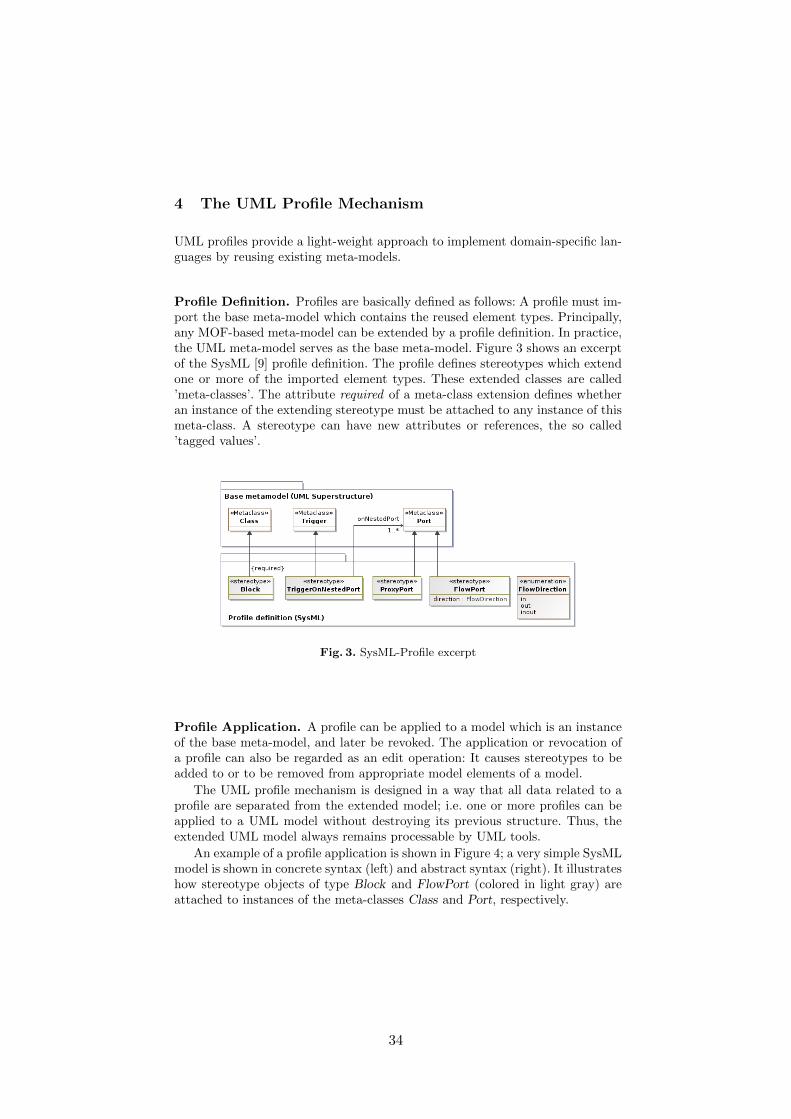
4 The UML Profile Mechanism
UML profiles provide a light-weight approach to implement domain-specific lan-guages by reusing existing meta-models.
Profile Definition. Profiles are basically defined as follows: A profile must im-port the base meta-model which contains the reused element types. Principally,any MOF-based meta-model can be extended by a profile definition. In practice,the UML meta-model serves as the base meta-model. Figure 3 shows an excerptof the SysML [9] profile definition. The profile defines stereotypes which extendone or more of the imported element types. These extended classes are called’meta-classes’. The attribute required of a meta-class extension defines whetheran instance of the extending stereotype must be attached to any instance of thismeta-class. A stereotype can have new attributes or references, the so called’tagged values’.
Fig. 3. SysML-Profile excerpt
Profile Application. A profile can be applied to a model which is an instanceof the base meta-model, and later be revoked. The application or revocation ofa profile can also be regarded as an edit operation: It causes stereotypes to beadded to or to be removed from appropriate model elements of a model.
The UML profile mechanism is designed in a way that all data related to aprofile are separated from the extended model; i.e. one or more profiles can beapplied to a UML model without destroying its previous structure. Thus, theextended UML model always remains processable by UML tools.
An example of a profile application is shown in Figure 4; a very simple SysMLmodel is shown in concrete syntax (left) and abstract syntax (right). It illustrateshow stereotype objects of type Block and FlowPort (colored in light gray) areattached to instances of the meta-classes Class and Port, respectively.
34
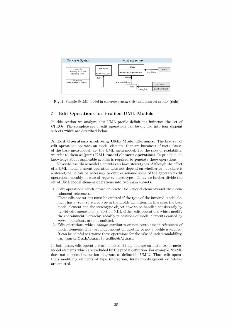
Fig. 4. Sample SysML model in concrete syntax (left) and abstract syntax (right)
5 Edit Operations for Profiled UML Models
In this section we analyze how UML profile definitions influence the set ofCPEOs. The complete set of edit operations can be divided into four disjointsubsets which are described below.
A. Edit Operations modifying UML Model Elements. The first set ofedit operations operates on model elements that are instances of meta-classesof the base meta-model, i.e. the UML meta-model. For the sake of readability,we refer to them as (pure) UML model element operations. In principle, noknowledge about applicable profiles is required to generate these operations.
Nevertheless, these model elements can have stereotypes. Although the effectof a UML model element operation does not depend on whether or not there isa stereotype, it can be necessary to omit or rename some of the generated editoperations, notably in case of required stereotypes. Thus, we further divide theset of UML model element operations into two main subsets:
1. Edit operations which create or delete UML model elements and their con-tainment references.These edit operations must be omitted if the type of the involved model ele-ment has a required stereotype in the profile definition. In this case, the basemodel element and the stereotype object have to be handled consistently byhybrid edit operations (s. Section 5.D). Other edit operations which modifythe containment hierarchy, notably relocations of model elements caused bymove operations, are not omitted.
2. Edit operations which change attributes or non-containment references ofmodel elements. They are independent on whether or not a profile is applied.It can be helpful to rename these operations for the sake of understandability,e.g. from setClassIsAbstract to setBlockIsAbstract.
In both cases, edit operations are omitted if they operate on instances of meta-model elements which are excluded by the profile definition. For example, SysMLdoes not support interaction diagrams as defined in UML2. Thus, edit opera-tions modifying elements of type Interaction, InteractionFragment or Lifelineare omitted.
35
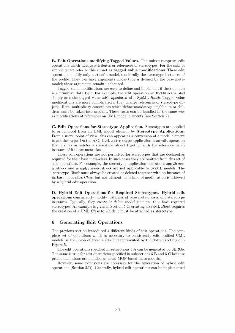
B. Edit Operations modifying Tagged Values. This subset comprises editoperations which change attributes or references of stereotypes. For the sake ofsimplicity, we refer to this subset as tagged value modifications. These editoperations modify only parts of a model, specifically the stereotype instances ofthe profile. They can have arguments whose type is defined by the base meta-model; these arguments remain unchanged.
Tagged value modifications are easy to define and implement if their domainis a primitive data type. For example, the edit operation setBlockIsEncapsulated
simply sets the tagged value isEncapsulated of a SysML Block. Tagged valuemodifications are more complicated if they change references of stereotype ob-jects. Here, multiplicity constraints which define mandatory neighbours or chil-dren must be taken into account. These cases can be handled in the same wayas modifications of references on UML model elements (see Section 2).
C. Edit Operations for Stereotype Application. Stereotypes are appliedto or removed from an UML model element by Stereotype Applications.From a users’ point of view, this can appear as a conversion of a model elementto another type. On the ASG level, a stereotype application is an edit operationthat creates or deletes a stereotype object together with the reference to aninstance of its base meta-class.
These edit operations are not permitted for stereotypes that are declared asrequired for their base meta-class. In such cases they are omitted from this set ofedit operations. For example, the stereotype application operations applyStereo-
typeBlock and unapplyStereotypeBlock are not applicable to SysML models. Thestereotype Block must always be created or deleted together with an instance ofits base meta-class Class, but not without. This kind of modification is achievedby a hybrid edit operation.
D. Hybrid Edit Operations for Required Stereotypes. Hybrid editoperations concurrently modify instances of base meta-classes and stereotypeinstances. Typically, they create or delete model elements that have requiredstereotypes. An example is given in Section 5.C; creating a SysML Block requiresthe creation of a UML Class to which it must be attached as stereotype.
6 Generating Edit Operations
The previous section introduced 4 different kinds of edit operations. The com-plete set of operations which is necessary to consistently edit profiled UMLmodels, is the union of these 4 sets and represented by the dotted rectangle inFigure 5.
The edit operations specified in subsections 5.A can be generated by SERGe.The same is true for edit operations specified in subsections 5.B and 5.C becauseprofile definitions are handled as usual MOF-based meta-models.
However, some extensions are necessary for the generation of hybrid editoperations (Section 5.D). Generally, hybrid edit operations can be implemented
36

using two different approaches: A higher-order transformation approach and ameta-model driven approach.
Fig. 5. Generation of different types of edit operations
A. Higher-order Transformation Approach. This approach uses a set ofexisting UML edit operations as primary input (see arrow 1 in Figure 5). It doesnot matter whether the edit operations have been generated and/or constructedmanually. The basic idea is to modify them by adding appropriate stereotypes.
We assume that edit operations are defined as executable specifications in theform of Henshin transformation rules as explained in Section 2. Henshin rulesare technically represented as models and can be transformed automatically, i.e.their modification can be considered as a higher-order transformation (HOT).
We have implemented this HOT in Henshin as follows: Basically, stereotypesas defined by the profile are applied to all instances of a UML base meta-classwhich occur in the given set of UML edit rules. A parametrized HOT rule isprovided in order to attach an instance of a stereotype. The necessary parametersare the stereotype and the UML meta-class. We have implemented three variantsof this HOT rule: They attach stereotype objects to UML model elements whichare (1) to be created, (2) to be deleted and (3) to be preserved by an edit rule.A working example of a HOT rule can be found at [12].
Since a UML meta-class can be extended by several stereotypes, differentvariants for every stereotype will be created. Such variants can also consist ofcombinations of multiple stereotypes, if more than one meta-class is containedin the given UML edit rule. Thus, the scheduling algorithm which applies theHOT rules with appropriate invocation arguments is responsible for generatingall possible combinations of stereotype attachments.
A big advantage of this approach is that efforts of manual adjustments onUML edit operations are not lost. A disadvantage is that it supports only simpleprofiles: It cannot handle stereotypes which have mandatory references to other
37
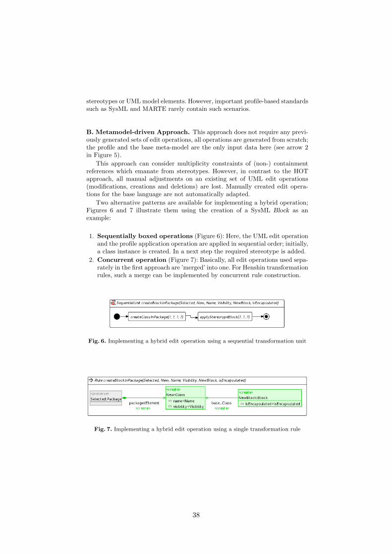
stereotypes or UML model elements. However, important profile-based standardssuch as SysML and MARTE rarely contain such scenarios.
B. Metamodel-driven Approach. This approach does not require any previ-ously generated sets of edit operations, all operations are generated from scratch;the profile and the base meta-model are the only input data here (see arrow 2in Figure 5).
This approach can consider multiplicity constraints of (non-) containmentreferences which emanate from stereotypes. However, in contrast to the HOTapproach, all manual adjustments on an existing set of UML edit operations(modifications, creations and deletions) are lost. Manually created edit opera-tions for the base language are not automatically adapted.
Two alternative patterns are available for implementing a hybrid operation;Figures 6 and 7 illustrate them using the creation of a SysML Block as anexample:
1. Sequentially boxed operations (Figure 6): Here, the UML edit operationand the profile application operation are applied in sequential order; initially,a class instance is created. In a next step the required stereotype is added.
2. Concurrent operation (Figure 7): Basically, all edit operations used sepa-rately in the first approach are ’merged’ into one. For Henshin transformationrules, such a merge can be implemented by concurrent rule construction.
Fig. 6. Implementing a hybrid edit operation using a sequential transformation unit
Fig. 7. Implementing a hybrid edit operation using a single transformation rule
38

7 Conclusion
This paper has presented our approach to construct complete sets of consistency-preserving edit operations on models. In contrast, existing approaches for gener-ating edit operations do not support consistency preservation and DSMLs usingUML Profiles such as SysML or MARTE.
We addressed an important practical requirement: How to consistently main-tain operation sets for the base language without profiles and for the profiledlanguage. Our solution is based on a clear separation of all edit operations in 4categories. The most complex type of edit operations are hybrid ones; we showedthat they can be implemented in such a way that manual optimizations of thebase edit operations can be preserved.
Acknowledgement. This work was partially supported by the DFG (GermanResearch Foundation) under the Priority Programme SPP1593: Design For Fu-ture - Managed Software Evolution.
References
1. Alanen, M.; Porres, I.: A relation between context-free grammars and meta objectfacility metamodels; Technical Report 606, TUCS Turku Center for ComputerScience; 2003;
2. Arendt, T.; Biermann, E.; Jurack, S.; Krause, C.; Taentzer, G.: Henshin: AdvancedConcepts and Tools for In-Place EMF Model Transformations; in: Proc. MoDELS2010, Oslo; LNCS 6394, Springer; 2010
3. Ehrig, K.; Kuster, J.M.; Taentzer, G.; Generating instance models from meta mod-els; SoSym Volume 8:4, p.479-500; 2009
4. EMF: Eclipse Modeling Framework; http://www.eclipse.org/emf; 20125. EMF Henshin Project; http://www.eclipse.org/modeling/emft/henshin6. Hoffmann, B.; Minas, M.: Generating instance graphs from class diagrams with
adaptive star grammars. Intl. Workshop on Graph Computation Models, 20117. Kehrer, T.; Kelter, U.; Taentzer, G.: Consistency-Preserving Edit Scripts in Model
Versioning; in: Proc. 28th IEEE/ACM Intl. Conf. on Automated Software Engi-neering (ASE 2013); ACM; 2013
8. Object Constraint Language: Version 2.0; OMG, Doc. formal/2006-05-01; 20069. Systems Modeling Language: Version 1.3; OMG, Doc. formal/2012-06-01; 2012
10. UML Profile For Marte - Modeling And Analysis Of Real-time Embedded System:Version 1.1; OMG, Doc. formal/2011-06-02; 2011
11. Pietsch, P.; Shariat Yazdi, H.; Kelter, U.: Generating Realistic Test Models forModel Processing Tools; p.620-623 in: Proc. 26th IEEE/ACM International Con-ference on Automated Software Engineering (ASE’11); ACM; 2011
12. The SiDiff EditRule Generator - A tool to automatically derive consistency-preserving edit operations of any ecore meta model; http://pi.informatik.uni-siegen.de/Mitarbeiter/mrindt/SERGe.php; 2012
13. Taentzer, G.: Instance Generation from Type Graphs with Arbitrary Multiplicities;in: Electronic Communication of the EASST 47; 2012
39
Evolution of Model Clones in Simulink
Matthew Stephan, Manar H. Alalfi, James R. Cordy, and Andrew Stevenson
Queen’s University,Kingston, Ontario, Canada
{stephan,alalfi,cordy,andrews}@cs.queensu.ca
Abstract. A growing and important area of Model-Based Development(MBD) is model evolution. Despite this, very little research on the evo-lution of Simulink models has been conducted. This is in contrast to thenotable amount of research on UML models, which di↵er significantlyfrom Simulink. Code clones and their evolution across system versionshave been used to learn about source-code evolution. We postulate thatthe same idea can be applied to model clones and model evolution. Inthis paper, we explore this notion and apply it to Simulink models. Wedetect model clones in successive versions of MBD projects and, witha new tool, track the evolution of model clones with respect to theircontaining clone classes. When there is a change in classification of amodel-clone, we investigate what specifically evolved in the model tocause this classification change.
Keywords: model evolution, model clone detection, model clone evolu-tion, Simulink
1 Introduction
Understanding software model evolution in Model-Based Development(MBD) is important as it can improve our ability to adapt to change, allows usto refactor more e�ciently, and increases the quality and amount of analysis wecan do on MBD projects. While still a relatively young area, there is a notableamount of work that discusses the evolution of UML models [5, 8, 10]. In contrast,there is very little research related to the evolution of Simulink models, a data-flow modeling language that is widely used in the automotive and communicationindustries, as well as other embedded areas. Simulink models di↵er significantlyfrom anything in UML, with the most analogous diagram being a UML activitydiagram, which is still quite di↵erent.
As noted in [13], there are a number of instances where code clones are used inorder to perform source-code evolution analysis. Specifically, once a relationshipcan be established between two versions of a system, it can be employed as ameans to understand the evolution of the system. Such a relationship can berealized by extracting code clones from di↵erent versions and then identifyingand analyzing similar groups and how they have changed. We believe the sameholds true for models. Thus, as a first step towards understanding Simulink
40
2 Matthew Stephan, Manar H. Alalfi, James R. Cordy, Andrew Stevenson
model evolution, we introduce the notion and use of Simulink model cloneevolution (MCE). We focus on Simulink because there is sparse research on itsevolution, it is of interest to our industrial partners, and Simulink model clonedetection (MCD) is the most mature form of MCD.
In this paper, we use our near-miss MCD tool, SIMONE [1], to detect clonesfrom successive versions of both industrial and publicly available models. Usinga new tool we develop, we are able to track the evolution of a model-clone class’clone instances throughout multiple versions. When there is a change in theclassification of the model-clone instance, we then delve deeper into the modelitself to see and illustrate what exactly has evolved that caused this changeand then explain it. The paper begins by providing background in Sect. 2 anddefining key terms in Sect. 3. We then present the tool we developed for thiswork in Sect. 4 and our experiments with it, along with examples of models andtheir evolution, in Sect. 5. We present related and future work in Sect. 6 andconclude in Sect. 7.
2 Background
2.1 Simulink
Simulink models consist of 3 levels of granularity: whole models, (sub) systems,and blocks. Models contain systems, and systems contain other (sub) systemsand blocks. This is similar to source files: models are like programs; systemsare like methods, functions, and classes; and blocks are like statements in tradi-tional programming languages. An important characteristic of Simulink modelsis “All block names in a model must be unique and must contain at least onecharacter.” 1
2.2 Clone Genealogies
Kim et al. [9] define the notion of genealogy for code clone groups as the way inwhich a collection of clones evolves over multiple versions of a system. The clonegroup evolution they describe is in terms of code snippets, which are comprisedof both text and location. For Kim et al.’s genealogies, each code clone groupcontains identical (exact) code clones which are matched to other clone groupsbased on textual similarity. Saha et al. [14] later consider clone groups contain-ing non-identical (near-miss) code clones and match them to other groups bymatching functions (code blocks) containing the code clones. We extend andmodify the concepts and approaches from these works in order to apply them toSimulink models.
2.3 Model Clone Detection
Much like its counterpart, code clone detection, model clone detection entailsdiscovering identical or similar fragments of model elements [4]. We recently
1 http://www.mathworks.com/help/simulink/ug/changing-a-blocks-appearance.html
41
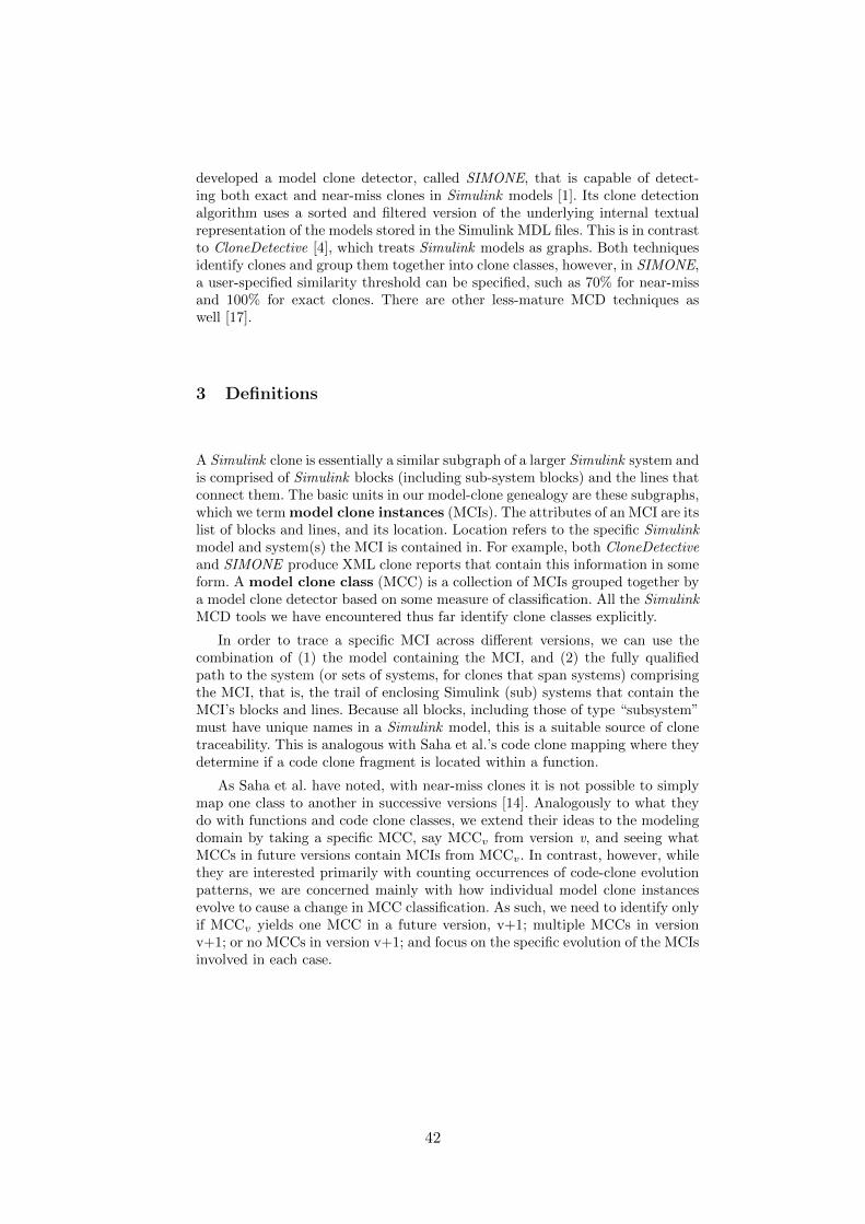
Evolution of Model Clones in Simulink 3
developed a model clone detector, called SIMONE, that is capable of detect-ing both exact and near-miss clones in Simulink models [1]. Its clone detectionalgorithm uses a sorted and filtered version of the underlying internal textualrepresentation of the models stored in the Simulink MDL files. This is in contrastto CloneDetective [4], which treats Simulink models as graphs. Both techniquesidentify clones and group them together into clone classes, however, in SIMONE,a user-specified similarity threshold can be specified, such as 70% for near-missand 100% for exact clones. There are other less-mature MCD techniques aswell [17].
3 Definitions
A Simulink clone is essentially a similar subgraph of a larger Simulink system andis comprised of Simulink blocks (including sub-system blocks) and the lines thatconnect them. The basic units in our model-clone genealogy are these subgraphs,which we term model clone instances (MCIs). The attributes of an MCI are itslist of blocks and lines, and its location. Location refers to the specific Simulinkmodel and system(s) the MCI is contained in. For example, both CloneDetectiveand SIMONE produce XML clone reports that contain this information in someform. A model clone class (MCC) is a collection of MCIs grouped together bya model clone detector based on some measure of classification. All the SimulinkMCD tools we have encountered thus far identify clone classes explicitly.
In order to trace a specific MCI across di↵erent versions, we can use thecombination of (1) the model containing the MCI, and (2) the fully qualifiedpath to the system (or sets of systems, for clones that span systems) comprisingthe MCI, that is, the trail of enclosing Simulink (sub) systems that contain theMCI’s blocks and lines. Because all blocks, including those of type “subsystem”must have unique names in a Simulink model, this is a suitable source of clonetraceability. This is analogous with Saha et al.’s code clone mapping where theydetermine if a code clone fragment is located within a function.
As Saha et al. have noted, with near-miss clones it is not possible to simplymap one class to another in successive versions [14]. Analogously to what theydo with functions and code clone classes, we extend their ideas to the modelingdomain by taking a specific MCC, say MCCv from version v, and seeing whatMCCs in future versions contain MCIs from MCCv. In contrast, however, whilethey are interested primarily with counting occurrences of code-clone evolutionpatterns, we are concerned mainly with how individual model clone instancesevolve to cause a change in MCC classification. As such, we need to identify onlyif MCCv yields one MCC in a future version, v+1; multiple MCCs in versionv+1; or no MCCs in version v+1; and focus on the specific evolution of the MCIsinvolved in each case.
42
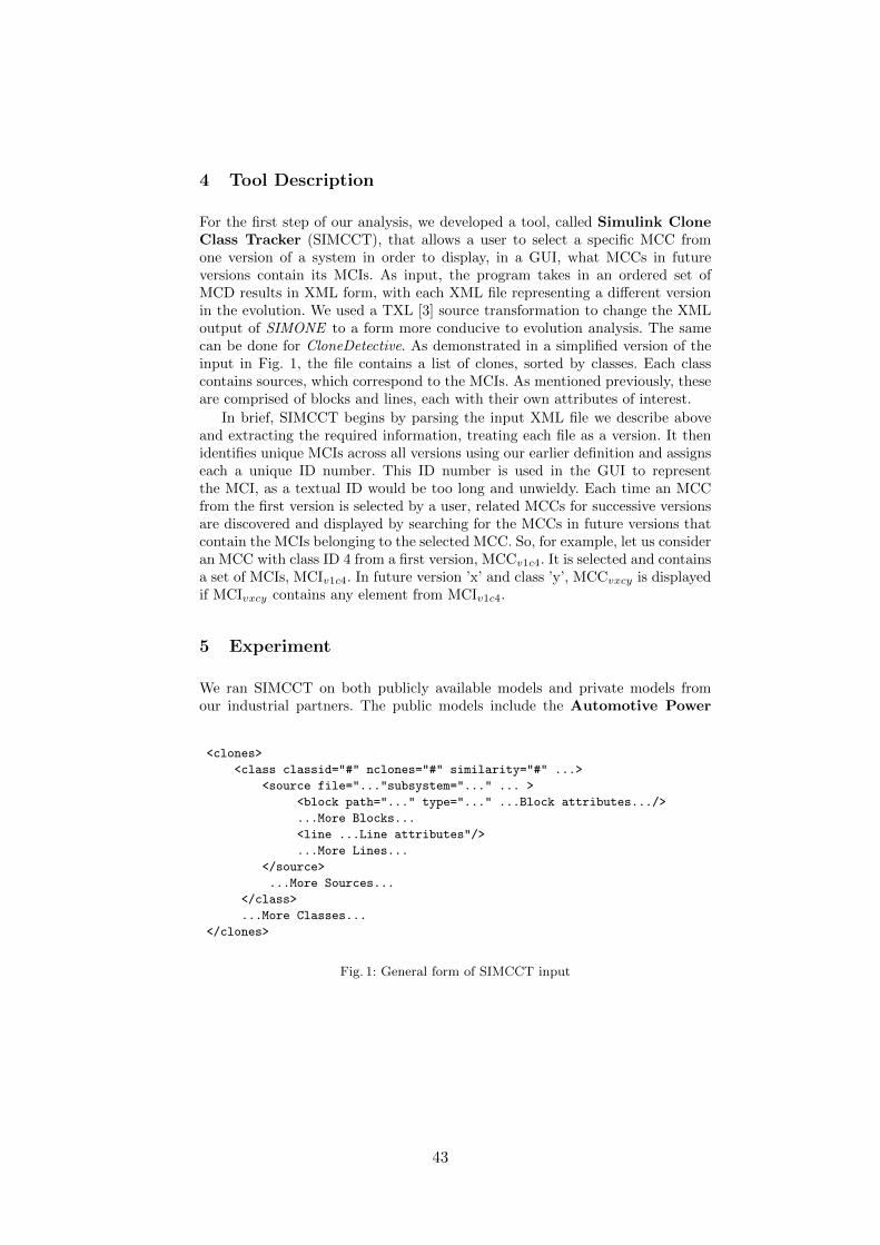
4 Matthew Stephan, Manar H. Alalfi, James R. Cordy, Andrew Stevenson
4 Tool Description
For the first step of our analysis, we developed a tool, called Simulink CloneClass Tracker (SIMCCT), that allows a user to select a specific MCC fromone version of a system in order to display, in a GUI, what MCCs in futureversions contain its MCIs. As input, the program takes in an ordered set ofMCD results in XML form, with each XML file representing a di↵erent versionin the evolution. We used a TXL [3] source transformation to change the XMLoutput of SIMONE to a form more conducive to evolution analysis. The samecan be done for CloneDetective. As demonstrated in a simplified version of theinput in Fig. 1, the file contains a list of clones, sorted by classes. Each classcontains sources, which correspond to the MCIs. As mentioned previously, theseare comprised of blocks and lines, each with their own attributes of interest.
In brief, SIMCCT begins by parsing the input XML file we describe aboveand extracting the required information, treating each file as a version. It thenidentifies unique MCIs across all versions using our earlier definition and assignseach a unique ID number. This ID number is used in the GUI to representthe MCI, as a textual ID would be too long and unwieldy. Each time an MCCfrom the first version is selected by a user, related MCCs for successive versionsare discovered and displayed by searching for the MCCs in future versions thatcontain the MCIs belonging to the selected MCC. So, for example, let us consideran MCC with class ID 4 from a first version, MCCv1c4. It is selected and containsa set of MCIs, MCIv1c4. In future version ’x’ and class ’y’, MCCvxcy is displayedif MCIvxcy contains any element from MCIv1c4.
5 Experiment
We ran SIMCCT on both publicly available models and private models fromour industrial partners. The public models include the Automotive Power
<clones>
<class classid="#" nclones="#" similarity="#" ...>
<source file="..."subsystem="..." ... >
<block path="..." type="..." ...Block attributes.../>
...More Blocks...
<line ...Line attributes"/>
...More Lines...
</source>
...More Sources...
</class>
...More Classes...
</clones>
Fig. 1: General form of SIMCCT input
43
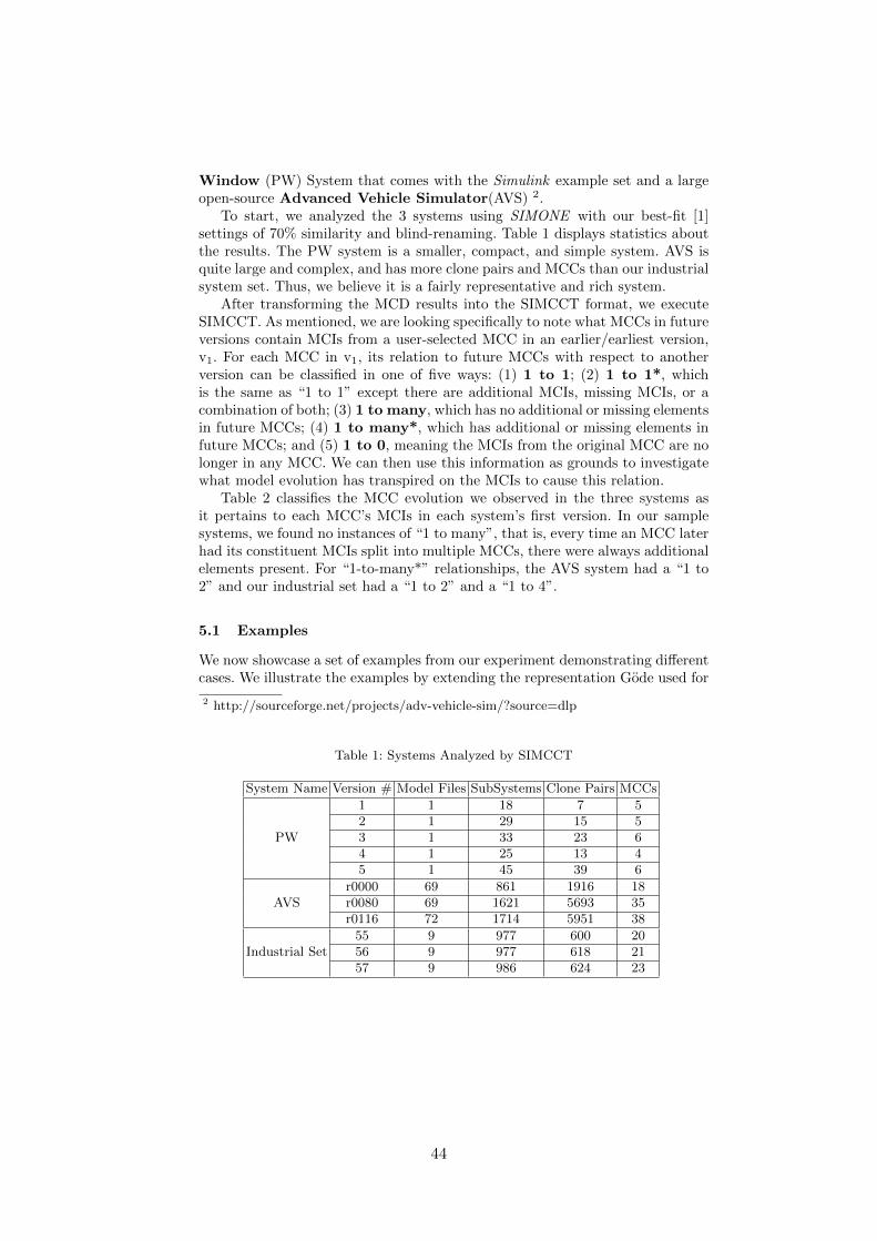
Evolution of Model Clones in Simulink 5
Window (PW) System that comes with the Simulink example set and a largeopen-source Advanced Vehicle Simulator(AVS) 2.
To start, we analyzed the 3 systems using SIMONE with our best-fit [1]settings of 70% similarity and blind-renaming. Table 1 displays statistics aboutthe results. The PW system is a smaller, compact, and simple system. AVS isquite large and complex, and has more clone pairs and MCCs than our industrialsystem set. Thus, we believe it is a fairly representative and rich system.
After transforming the MCD results into the SIMCCT format, we executeSIMCCT. As mentioned, we are looking specifically to note what MCCs in futureversions contain MCIs from a user-selected MCC in an earlier/earliest version,v1. For each MCC in v1, its relation to future MCCs with respect to anotherversion can be classified in one of five ways: (1) 1 to 1; (2) 1 to 1*, whichis the same as “1 to 1” except there are additional MCIs, missing MCIs, or acombination of both; (3) 1 to many, which has no additional or missing elementsin future MCCs; (4) 1 to many*, which has additional or missing elements infuture MCCs; and (5) 1 to 0, meaning the MCIs from the original MCC are nolonger in any MCC. We can then use this information as grounds to investigatewhat model evolution has transpired on the MCIs to cause this relation.
Table 2 classifies the MCC evolution we observed in the three systems asit pertains to each MCC’s MCIs in each system’s first version. In our samplesystems, we found no instances of “1 to many”, that is, every time an MCC laterhad its constituent MCIs split into multiple MCCs, there were always additionalelements present. For “1-to-many*” relationships, the AVS system had a “1 to2” and our industrial set had a “1 to 2” and a “1 to 4”.
5.1 Examples
We now showcase a set of examples from our experiment demonstrating di↵erentcases. We illustrate the examples by extending the representation Gode used for
2 http://sourceforge.net/projects/adv-vehicle-sim/?source=dlp
Table 1: Systems Analyzed by SIMCCT
System Name Version # Model Files SubSystems Clone Pairs MCCs
PW
1 1 18 7 52 1 29 15 53 1 33 23 64 1 25 13 45 1 45 39 6
AVSr0000 69 861 1916 18r0080 69 1621 5693 35r0116 72 1714 5951 38
Industrial Set55 9 977 600 2056 9 977 618 2157 9 986 624 23
44

6 Matthew Stephan, Manar H. Alalfi, James R. Cordy, Andrew Stevenson
Table 2: Relationship Classifications of MCCs w.r.t. Earliest Versions
System Name Version 1 to 1 1 to 1* 1 to many 1 to many* 1 to 0
PW
2 1 4 0 0 03 1 4 0 0 04 1 3 0 0 15 1 2 0 0 2
AVSr0080 12 5 0 1 0r0116 9 8 0 1 0
Industrial Set56 14 4 0 2 057 14 4 0 2 0
the evolution of type-1 code clones [6], with MCCs being rectangles and MCIsbeing circles. In addition, we provide figures of some of the examples showcasingthe specific evolution that has transpired. This is in order to highlight samplesof changes that form various evolutionary MCC relationships.
We choose examples from public models as they adequately exhibit the casesand are available to all. We then investigate what evolution has taken place onthe models themselves that caused the observed MCE. A reminder, each numberwithin a circle refers to a uniquely identified key that corresponds to a uniqueMCI across all versions.
Power Window - Model Clone Class 3: This example is presented in Figs. 2and 3. It contains MCC3, which begins with two MCIs, 5 and 6, that are 81%similar. In version 2, represented by the part underneath the dashed line in Fig. 3,MCI6 has 2 additional blocks and no longer belongs to any MCC. Conversely,MCI5 is simplified by replacing three blocks with one and is now 71% similar toMCI7 and other MCIs, causing a reclassification with them. Starting in version 4,MCI5 is simplified even further by removing more blocks and no longer belongsto any MCC. As such, MCC3 has a “1-to-0” relation to versions 4 and 5.
Fig. 2: PW MCC3 SIMCCT Trace
45
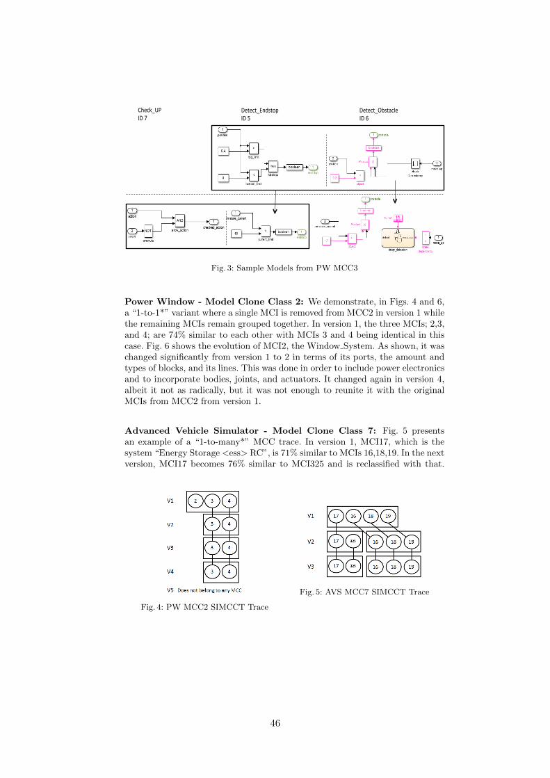
Evolution of Model Clones in Simulink 7
!"#"$#%&'()#*+,-!,.,
!"#"$#%/0)#1$2",-!,3,
45"$6%78,-!,9,
Fig. 3: Sample Models from PW MCC3
Power Window - Model Clone Class 2: We demonstrate, in Figs. 4 and 6,a “1-to-1*” variant where a single MCI is removed from MCC2 in version 1 whilethe remaining MCIs remain grouped together. In version 1, the three MCIs; 2,3,and 4; are 74% similar to each other with MCIs 3 and 4 being identical in thiscase. Fig. 6 shows the evolution of MCI2, the Window System. As shown, it waschanged significantly from version 1 to 2 in terms of its ports, the amount andtypes of blocks, and its lines. This was done in order to include power electronicsand to incorporate bodies, joints, and actuators. It changed again in version 4,albeit it not as radically, but it was not enough to reunite it with the originalMCIs from MCC2 from version 1.
Advanced Vehicle Simulator - Model Clone Class 7: Fig. 5 presentsan example of a “1-to-many*” MCC trace. In version 1, MCI17, which is thesystem “Energy Storage <ess> RC”, is 71% similar to MCIs 16,18,19. In the nextversion, MCI17 becomes 76% similar to MCI325 and is reclassified with that.
Fig. 4: PW MCC2 SIMCCT Trace
Fig. 5: AVS MCC7 SIMCCT Trace
46

8 Matthew Stephan, Manar H. Alalfi, James R. Cordy, Andrew Stevenson
Fig. 6: Evolution of the PW Window System
MCI17’s evolution involved many low-level structural changes, and as such, isnot worth showing a diagram of. So, while the model remained the same interms of layout, there were some key non-visual changes including modificationof block types, the addition or explication of ports, and changing a block’s keyparameters, for example, changing a Gain block’s multiplication mode.
6 Related and Future Work
6.1 Related Work
As mentioned already, Saha et al. [14] are focused on counting the occurrencesof code clone genealogies. In contrast, we are more interested in reasoning aboutthe changes to models that cause MCE and use the genealogy of the MCCs asthe starting point only.
There are some language-agnostic model and metamodel evolutionapproaches [7, 12] that can track both evolution and co-evolution. However, inorder to use techniques like this for MCE, we would essentially have to createa system containing only the clones of interest. As such, we developed a toolexplicitly intended to perform model clone class evolution analysis.
There are some model comparison approaches [16, 17] that can find simi-larities and di↵erences among models for versioning and other purposes, butthere are no attempts to explicate the structural evolution of Simulink models.That is, to define what are the potential structural changes that can occur toa Simulink model and their prevalence. Model evolution and MCE are stronglyrelated to model comparison and versioning, but can be viewed as a longer-termanalysis over multiple versions with a focus on how a specific artifact or clonehas changed. None of the model comparison techniques we surveyed previouslywere ideal for tracking MCE.
47

Evolution of Model Clones in Simulink 9
The only work that deals with any form of Simulink evolution is from Tranand Kreuz, who focus on refactoring Simulink [11]. Specifically, they look atforms of antipatterns in Simulink and discuss tool support for correcting them.
6.2 Future Work
One area of future work is providing better di↵erencing and visualization of dif-ferences for Simulink models. So far, we’ve been doing it relatively manually.While there are many model comparison tools [16, 17] that provide visualiza-tion functionality, there are none well-suited for our purposes and the providedSimulink XML comparison functionality is inadequate as it does not capturethe information we desire. As such, devising and automating the di↵erencingand visualization for MCE purposes and incorporating it into SIMCCT wouldbe ideal.
In addition, we are currently working on MCD for other model types, includ-ing Stateflow and behavioral UML models [2]. We believe our work on MCE canbe applied to other model types; Specifically, as long as an MCD tool identifiesboth MCCs and MCIs, these concepts can be extended and an appropriate cloneclass tracker can be developed. This is something that we will investigate onceour MCD techniques for these other model types are more mature.
In the long term, we plan on enumerating a set of Simulink model evolutionsas they relate to model clone evolution. The purpose in doing this is to finda su�cient set for performing MCD evaluation in a mutation-based frameworkas discussed in [15]. So, in addition to all the previously mentioned benefits ofobserving model evolution, we plan on using this work to help with mutationresearch intended to realize model-clone tool evaluation.
7 Conclusions
We believe MCE research is quite valuable as it can be a useful tool for betterunderstanding how Simulink and other data-flow models evolve. In this paper,we took some first steps towards understanding Simulink MCE. We began bydefining key terms, including model clone classes and instances. SIMCCT is atool we introduced that is capable of tracking an MCI’s evolution with respectto its containing MCCs across di↵erent system versions. We used this tool onthree systems, share our findings, and go into details for a few examples. Theseexamples included looking at the model evolution that transpired causing thespecific MCE observed. In the future, we plan on automating the di↵erencingand visualization of the model evolution for a given MCE trace as well as enu-merating the Simulink model evolution steps that cause MCC changes. Thisand other Simulink and data-flow MCE work can go a long way towards im-proving our relatively underdeveloped understanding of the model evolution ofthese technologies.
48
10 Matthew Stephan, Manar H. Alalfi, James R. Cordy, Andrew Stevenson
Acknowledgments
This work is supported by NSERC, the Natural Sciences and Engineering Re-search Council of Canada, as part of the NECSIS Automotive Partnership withGeneral Motors, IBM Canada and Malina Software Corp.
References
1. Alalfi, M.H., Cordy, J.R., Dean, T.R., Stephan, M., Stevenson, A.: Models are codetoo: Near-miss clone detection for Simulink models. In: ICSM. pp. 295–304 (2012)
2. Antony, E., Alalfi, M., Cordy, J.: An approach to clone detection in behaviouralmodels. In: WCRE. p. 5 (2013), (to appear)
3. Cordy, J.: The TXL source transformation language. Science of Computer Pro-gramming 61(3), 190–210 (2006)
4. Deissenboeck, F., Hummel, B., Juergens, E., Schaetz, B., Wagner, S., Girard, J.F.,Teuchart, S.: Clone detection in automotive model-based development. In: ICSE.pp. 603–612 (2009)
5. France, R., Bieman, J.M.: Multi-view software evolution: a uml-based frameworkfor evolving object-oriented software. In: ICSM. pp. 386–395 (2001)
6. Gode, N.: Evolution of type-1 clones. In: SCAM. pp. 77–86 (2009)7. Herrmannsdoerfer, M., Benz, S., Juergens, E.: Cope-automating coupled evolution
of metamodels and models. In: ECOOP 2009, pp. 52–76 (2009)8. Keienburg, F., Rausch, A.: Using XML/XMI for tool supported evolution of UML
models. In: HICSS. vol. 9, p. 9064 (2001)9. Kim, M., Sazawal, V., Notkin, D., Murphy, G.: An empirical study of code clone
genealogies. ESEC/FSE-13 30(5), 187–196 (2005)10. Mens, T., Lucas, C., Steyaert, P.: Supporting disciplined reuse and evolution of
UML models. UML98: Beyond the Notation pp. 378–392 (1999)11. Minh Tran, Q., Kreuz, I.: Refactoring of simulink models. In: MathWorks Auto-
motive Conference, Stuttgart (2012)12. Rose, L.M., Kolovos, D.S., Paige, R.F., Polack, F.A.: Model migration with epsilon
flock. In: Theory and Practice of Model Transformations, pp. 184–198. Springer(2010)
13. Roy, C.K., Cordy, J.R.: A survey on software clone detection research. Tech. Rep.2007-541, Queen’s University (2007)
14. Saha, R.K., Roy, C.K., Schneider, K.A.: An automatic framework for extractingand classifying near-miss clone genealogies. In: ICSM. pp. 293–302 (2011)
15. Stephan, M., Alafi, M., Stevenson, A., Cordy, J.: Using mutation analysis for amodel-clone detector comparison framework. In: ICSE. pp. 1277–1280 (2013)
16. Stephan, M., Cordy, J.R.: A survey of methods and applications of model compar-ison. Tech. Rep. 2011-582 Rev. 3, Queen’s University (2012)
17. Stephan, M., Cordy, J.R.: A survey of model comparison approaches and applica-tions. In: MODELSWARD (2013)
49
Proactive Quality Guidancefor Model Evolution in Model Libraries
Andreas Ganser1, Horst Lichter1, Alexander Roth2, and Berhard Rumpe2
1 RWTH Aachen University, Ahornstr. 55, 52074 Aachen, Germany{ganser, lichter}@swc.rwth-aachen.de,
home page: http://www.swc.rwth-aachen.de2 RWTH Aachen University, Ahornstr. 55, 52074 Aachen, Germany
{roth, rumpe}@se.rwth-aachen.de,home page: http://www.se.rwth-aachen.de
Abstract. Model evolution in model libraries di↵ers from general modelevolution. It limits the scope to the manageable and allows to developclear concepts, approaches, solutions, and methodologies. Looking atmodel quality in evolving model libraries, we focus on quality concernsrelated to reusability.In this paper, we put forward our proactive quality guidance approachfor model evolution in model libraries. It uses an editing-time assessmentlinked to a lightweight quality model, corresponding metrics, and sim-plified reviews. All of which help to guide model evolution by means ofquality gates fostering model reusability.
Keywords: Model Evolution, Model Quality, Model Libraries
1 The Need for Proactive Quality Guidance
Modeling is one of the traditional disciplines in computer sciences and other sci-ences. Therefore, computer scientists have been creating models for decades andhave seen models incarnate in a lots of di↵erent forms. Interestingly enough thatthe general modeling theory was not developed by a computer scientist but byHerbert Stachowiak in the seventies [Stachowiak, 1973]. His work found impactin a lot of domains in computer sciences, e.g. databases, resulting in researchlike generic model management [Melnik, 2004]. This transforms Stachowiak’srather abstract theories to an applicable approach o↵ering concepts and algo-rithms, e.g., diff, merge, similarity, and match operations. As a result, pureoperations on models did not seem to be challenging any more and a broaderperspective was investigated.
A similar development took place in object oriented modeling which broughtup UML as a suitable modeling language. Today, the success of UML is of-ten accredited for two reasons. First, UML is believed to be an e↵ective lan-guage, because “for larger and distributed projects, UML modeling is believedto contribute to shared understanding of the system and more e↵ective commu-nication” [Chaudron et al., 2012]. Second, UML is considered as the de facto
50

II
standard in modeling. Due to that, a lot of tools were developed around UMLincluding code generators. They bolster approaches like rapid prototyping ormodel driven development (MDD) and allow modelers to deal with complexityon an appropriate level of abstraction.
Consequently, UML models are widely used and can be regarded as projectassets that should be reused. Moreover, it is believed that model reuse coulddecrease development time while increasing software quality [Mens et al., 1999,Lange and Chaudron, 2005], because best practices and experience would beleveraged. But the question is how to store models in a way that their qual-ity is maintained or even improved over time. Certainly, model reuse requires aninfrastructure enabling to persist models in a library or knowledge base. Further-more, it needs a means to control model evolution and quality in the long run.Unfortunately, quality is a matter of subjectivity, often relative to requirementsand sometimes hard to measure [Moody, 2005]. Moreover, all-at-once quality as-sessments result in endless quality reports that are hard to work through. Oneway out is edit-time quality assessment and guidance for assuring a certain levelof quality in model libraries, we call proactive quality guidance. To the best ofour knowledge we could not find such an approach for model libraries.
Hence, we looked into recent research (section 2) and found that model evolu-tion is often considered as a goal. That would be self-defeating in model libraries.So, we adopted the meaning of model evolution to fit model libraries and devel-oped an approach (section 3) that explains how models should evolve in modellibraries. This enables us to discuss model evolution in model libraries on a moreformal and qualitative level. In detail, we introduce our understanding of modelquality and quality gates. After that we explain our proactive approach includ-ing tool support by defining a mapping between a lightweight quality model andmetrics (section 4). This mostly deals with syntactic aspects, so we introducedsimple reviews (section 5) for the mostly semantic and pragmatic aspects.
2 Related Work
Model evolution, as we will present, can be discussed closely related to model li-braries and model quality. In the following, we present the current understandingof model evolution, model repositories, and model quality.
Model evolution is often investigated as a goal to be achieve automaticallyby tool support; as it is for software. There are several tools and research proto-types available. First, COPE supports evolution and co-evolution by monitoringchanges in an operation based way. These can be applied as editing traces toother models, i.e., forwarded [Herrmannsdoerfer and Ratiu, 2010]. Our approachdi↵ers in a regard that we do not trace changes but focus on edit-time changesand their impact on quality aspects. Second, MoDisco [Eclipse, 2012] (hostedwith AM3 [Allilaire et al., 2006]) tries to provide means to support evolution oflegacy systems applying model-driven ideas. That means, MoDisco is a tool forre-engineering legacy software by means of models and starting a model drivendevelopment from gleaned models. Moreover, co-evolution is discussed. We keep
51
III
to plain model evolution, but the main distinction to our approach is that wewant evolution to be guided and directed instead of being aimlessly.
Regarding model repositories one needs to bare in mind their functional-ity. Often, they allow for querying, conflict resolution, and version managementbut no more. This means, evolution and co-evolution are not considered. Exam-ples are, first, MOOGLE, a user friendly model search engine o↵ering enhancedquerying [Lucredio et al., 2010]. Second, ReMoDD which focuses on comunitybuilding by o↵ering models in a documentary sense to the community [Franceet al., 2007]. Mind that all of these model libraries do not consider model evo-lution. Consequently, we have implemented an enhanced model library [Ganserand Lichter, 2013], o↵ering model evolution as presented below.
This evolution support was enhanced by ideas regarding quality in modelingby Moody [Moody, 2005], because we wanted to establish a common under-standing of model quality in our library avoiding that “quality is seen as a sub-jective and rather social than a formally definable property lacking a commonunderstanding and standards” [Moody, 2005]. This is why we took the qualitydimensions by Lindland et al. [Lindland et al., 1994] and applied them in ourenvironment. They comprise syntactic, semantic, and pragmatic quality bearingin mind that these quality dimensions can influence each other as presented byBansiya et al. [Bansiya and Davis, 2002]. Looking at UML models, there ex-ist manifold model qualities. We chose the work of Lange et al [Lange, 2006]to be most suitable and linked it with metrics. There we employed the workof Genero et al. [Genero et al., 2003], Wedemeijer et al. [Wedemeijer, 2001],and Mohagheghi et al. [Mohagheghi and Dehlen, 2009]. Furthermore, we neededmeans to assess some semantical and pragmatical aspects. Here we root ourideas on reviews but found Fagans approach to heavyweight [Fagan, 1976]. Sowe subdivided review tasks using an adoption of the thinking hats as proposedby De Bono [De Bono, 2010].
3 Quality Staged Evolution
General model evolution is to be distinguished from model evolution in modellibraries [Roth et al., 2013] since the purpose di↵ers. While general model evo-lution is considered aimless, evolution in model libraries does not make sense ifit is undirected. This is due to the reuse focus of model libraries and the factthat these models mostly represent a starting point for modeling. Consequently,models in model libraries do not strive for perfection in every possible deploy-ment scenario but rather an eighty percent solution that will need adaption.Still, evolution in model library needs a sound foundation and tool support.
We developed an approach for quality assured model evolution in a gated andstaged manner [Roth et al., 2013]. It defines our approach to model evolution inmodel libraries and how it can be guided. In the remainder of this section, wewill shortly describe the quality staged model evolution approach.
52

IV
3.1 Quality and Evolution in Model Libraries
During modeling some parts of a model might seem so generic or generallyreusable that a modeler decides to put them in a model library. This means,some parts of the model are extracted, prepared for reuse, and stored in a modellibrary. At the same time, the modeler annotates the extracted model with asimplified specification, we call model purpose. It is supposed to grasp the mainintention of the model and reflect the general idea in a few words so this modelis explained in a complementary way. As all of this is done, we consider this themoment model evolution of this particular model starts.
JukeboxDAOrecords[]: Vinyl
Jukeboxplay()
Medium Credit
Snapshot 1 Snapshot 2 Snapshot 3
coins[]: Coin
pay()
play()
Jukeboxdiscs: MediaSetcredits[]: Credit
play() pay()
titles[]: String processPay()convertInput()
discs credits
costs[]: Credit
Fig. 1. Model Evolution Example
Reasons for model evolution in model libraries can be best explained con-sidering figure 1 as an example. Certainly, the first snapshot of this model isreusable, but some modeling decisions might be questionable. Furthermore, themodel is not free from technological details. The “DAO” su�x in the class nameis a clumsy leftover that should be removed quickly. Due to that, we o↵er editingsupport so models can be overwritten in a versioning style and call a version ofa model in our approach a model snapshot.
A few snapshots might be necessary to get a well designed and reusablemodel. Since all of them are persisted, one can order these snapshots as shownin figure 1 and assign numbers to each snapshot forming an evolution sequence.
This evolution sequence can be subdivided into subsequences annotated withstages that make a statement regarding reusability. We conducted a field studyabout the number and the names and found that “vague”, “decent”, and “fine”are the best representatives and assigned the colors “red”, “yellow”, and “green”respectively (cf. figure 2(b)). This is meant to provide an intuitive representationof the model’s reusability and the underlying formalities [Roth et al., 2013], sincewe do not want to bother modelers with the state machine formalizing the states.
The modeler just needs to know the semantics behind each stage. First, a“vague” model might contain some awkward design or leftovers from the origi-nating environment saying: “Be careful reusing this!”. Second, a “decent” modelis considered reusable in general, but might contain some pragmatic or semanticmismatch between the given purpose and the actual model. This stage is best
53
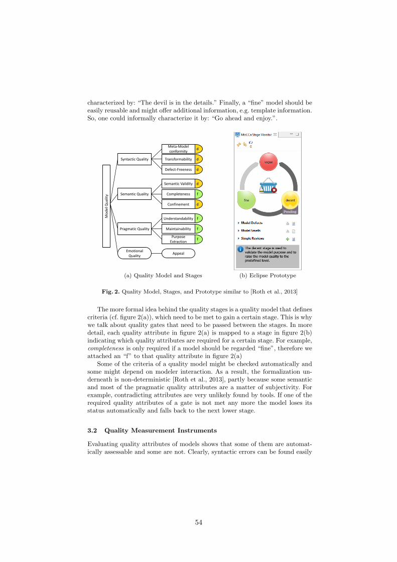
V
characterized by: “The devil is in the details.” Finally, a “fine” model should beeasily reusable and might o↵er additional information, e.g. template information.So, one could informally characterize it by: “Go ahead and enjoy.”.
f
f
f
d
f
d
d
d
d
Mod
el Q
ualit
y
Syntactic Quality
Semantic Quality
Pragmatic Quality
Emotional Quality
Meta-Model conformity
Transformability
Defect-Freeness
Semantic Validity
Completeness
Confinement
Understandability
Maintainability
PurposeExtraction
Appeal
(a) Quality Model and Stages (b) Eclipse Prototype
Fig. 2. Quality Model, Stages, and Prototype similar to [Roth et al., 2013]
The more formal idea behind the quality stages is a quality model that definescriteria (cf. figure 2(a)), which need to be met to gain a certain stage. This is whywe talk about quality gates that need to be passed between the stages. In moredetail, each quality attribute in figure 2(a) is mapped to a stage in figure 2(b)indicating which quality attributes are required for a certain stage. For example,completeness is only required if a model should be regarded “fine”, therefore weattached an “f” to that quality attribute in figure 2(a)
Some of the criteria of a quality model might be checked automatically andsome might depend on modeler interaction. As a result, the formalization un-derneath is non-deterministic [Roth et al., 2013], partly because some semanticand most of the pragmatic quality attributes are a matter of subjectivity. Forexample, contradicting attributes are very unlikely found by tools. If one of therequired quality attributes of a gate is not met any more the model loses itsstatus automatically and falls back to the next lower stage.
3.2 Quality Measurement Instruments
Evaluating quality attributes of models shows that some of them are automat-ically assessable and some are not. Clearly, syntactic errors can be found easily
54

VI
by parsers, but completeness is in the eye of the beholder. Consequently, wemake a distinction regarding model quality measurement instruments in threecategories: strong, medium, and weak characteristics. This classification enablesa mapping from model qualities (cf. figure 2(a)) to quality measurement instru-ments, where each attribute is used to derive a feedback with respect to theattribute name.
Strong characteristics form the strictest type. They can be measured pre-cisely using model metrics. A model metric is formulated with respect to modelsand provides clear feedback including the reason for the improvement and thesuggested solution. For example, a model including a class without a name. Be-sides, model metrics strong characteristics can be measured with external tools,e.g. EMF validator and EMF generator [Steinberg et al., 2009]. With respect toour quality model in figure 2(a), strong characteristics can be used to derive feed-back of the following model quality characteristics: defect-freeness, meta-modelconformity, and transformability.
Medium characteristics are based on Fowler’s idea of smells [Fowler, 1999].A smell is something that does not seem to be right and can be measured insome way. For example, a model with hundreds of classes is harder to understandthan one with only a few. Such characteristics can be measured with metrics,which define a clear threshold. However, this threshold can be overridden, if themodeler does not agree. Medium characteristics can be used to derive informationfor confinement, understandability, and maintainability.
Finally, weak characteristics can be compared to hunches. A hunch is some-thing that does not seem to be right because of gut feelings, experience, orintuition. Clearly, it is hard to measure such weak characteristics using metrics.We present simplified reviews in section 5 that enable assessing weak character-istics in a quick and precise way. Such model reviews allow to derive qualitativefeedback on semantic validity, completeness, purpose extraction, and appeal.
4 Proactive Quality Assessment
Quality measurement instruments and a quality model are used to assess thequality of a model. Such an assessment is, generally, triggered manually at acertain point in time. At this point, the model is analyzed and a report is created,which identifies improvements of the model. Clearly, such improvements canbe very vague making the cause for an improvement or a suggested solutionhard to understand. Additionally, such events that trigger model assessment aremostly of manual nature, i.e., triggered by someone. Consequently, to preventlong assessment reports with dozens improvement suggestions, such assessmentevents should be triggered automatically and more importantly periodically.
Proactive quality guidance is an approach that triggers assessment eventsautomatically and regards the iterative nature of model creation, i.e., the finalmodel is created in multiple iterations. During model creation the assessmentis triggered whenever the model has been changed. The model is analyzed andfeedback is presented to the modeler. Because the assessment is triggered when
55

VII
a model is changed, the resulting assessment iterations are kept small avoidinglarge reports and improvement suggestions. Due to constant and precise feedbackduring model creation the model evolution is guided and such detected violationswith respect to the quality model in section 3.1.
The main parts of proactive quality guidance are (a) automatic and constantassessment of the model, which is currently created, and (b) clear instructionson where the improvements have to be made and why. Automatic assessmentis executed when the model is changed but clear and instructive feedback ischallenging, because it identifies areas of improvement and their cause and mustalways be correct. Otherwise, modelers will be annoyed by false feedback. How-ever, the subjective nature of model quality makes it hard to always derivecorrect feedback without manual interaction.
As the underlying source of information for feedback are quality measurementinstruments, we applied the classification of quality measurement instruments,as presented in section 3.2, to structure feedback and, thereby, to loosen up therestriction of always correct feedback. Always correct feedback relies on strongcharacteristics, which can be measured precisely by using metrics, e.g. if a classhas duplicate methods. Furthermore, feedback relies on medium characteristics,which are less precise than strong characteristics, are only suggestions and canbe ignored by the modeler. For instance, methods with long parameter listsshould be avoided to not pass everything as a parameter. A list of all strong andmedium characteristics metrics is listed in [Roth, 2013]. Finally, weak character-istics regard the subjective nature of model quality and, consequently, are hardto measure. In consequence, we present an approach to simplify reviews andto enable measurement of weak characteristics. Such weak quality measurementinstruments can then be used to provide feedback.
5 Simplified Reviews
Metrics enable proactive quality assessment for strong and medium character-istics but for some weak characteristics proactive quality assessment is di�cult.At best heuristics can support modelers but they are unlikely to overrule expe-rience or gut feeling. For example, purpose extraction can be checked partiallyby keyword comparison but the modeler must have the last word. This is whywe researched on simplifying reviews as a means to quickly quality check theseand weaker characteristics.
Our result is an approach, we call simplified reviews, that separates di↵erentaspects of reviews by altering a technique used in parallel thinking [De Bono,2010]. These “Six Thinking Hats” provide a separation of concerns for each rolewhich is behind each hat directing tasks clearly. In our simplified reviews thisleads to reviews that take no longer than absolutely necessary:
In total five review roles remained because a role for controlling is not nec-essary for this approach. The hats are designed as follows: A Yellow Hat Review(Good points judgment) considers positive aspects of a model and a high numberindicates better quality. For example, a review might emphasize that a model is
56

VIII
of high benefit in maintenance. The Black Hat Review (Bad points judgment)can be regarded as the most known type of reviews. It is used to criticize point-ing out di�culties, dangers, defects, or bad design. A black hat review indicatesthat the corresponding model needs to be patched immediately. A White Hat Re-view (Information) is used to provide information or ask for information, whichcannot be gleaned from the model. For example, if a modeler has expertise onlimitations of the model, this should be documented by a white hat review. TheGreen Hat Reviews (Creativity) are a means to provide information about possi-ble improvements or new ideas. For a model library this review type is an integralpart to foster evolution and to keep modelers satisfied in the long run. Finally,in a Red Hat Review (Emotions) a reviewer can express a general attitude interms of like and dislike. For example, this can be a dislike based on experiencethat might help improving a model in future.
All of the simple reviews need no more than very simple tool support. A lookat figure 2(b) shows an entry that reads “Simple Reviews” with a plus buttonright next to it. Clicking this button opens a small window that allows to selectthe type of the simple review and entering additional text. Moreover, the treeeditor can be unfolded if there are simple reviews related to this model. Thenevery review can be inspected and checked “done” or “reopened”. This is a bitsimilar to a very lightweight issue tracking system.
6 Proactive Quality Guidance in a Nutshell
General model evolution is to be distinguished from model evolution in modellibraries as we briefly discussed above. This is due to unguided evolution beingself-defeating for model libraries. Due to that guidance is required to keep modelsreusable. Moreover, a model library with a focus on reuse puts constraints on aquality model for models that makes it manageable.
All in all, we have shown how models should evolve in model libraries withproactive quality guidance. Therefore, we illustrated how a quality model formodel library can be used to guide and stage model evolution in model libraries.To achieve this, we broke down the stages “vague”, “decent”, and “fine” toquality characteristics which are assured in di↵erent ways. While strong charac-teristics are checked automatically, medium and weak characteristics require userinteraction. But this interaction is supported in two ways. On the one hand, formedium characteristics some metrics provide assessments that only need to bejudged by a user because certain constraints like thresholds might not hold truefor a particular case. On the other hand, for weak characteristics, we introducedsimple reviews that allow quick and guided evaluations.
Since all this takes place during editing time, we call this approach proactivequality guidance. But there is more, because a lot of metrics allow to deriverecommendations how to fix certain issues. We use other published experienceto do so and implemented a prototype that realizes the entire approach. It lookssimple and clean, because we tried to avoid as much noise for modelers as possibleso the modeler does not get distracted while modeling.
57

IX
Acknowledgements
We would like to thank all our anonymous reviewers for their comments ande↵ort. We would also like to thank all our participants in our surveys and studies.
References
[Allilaire et al., 2006] Allilaire, F., Bezivin, J., Bruneliere, H., and Jouault, F. (2006).Global Model Management in Eclipse GMT/AM3. In Proceedings of the EclipseTechnology eXchange workshop (eTX) at the ECOOP 2006 Conference.
[Bansiya and Davis, 2002] Bansiya, J. and Davis, C. (2002). A hierarchical model forobject-oriented design quality assessment. IEEE Transactions on SE.
[Chaudron et al., 2012] Chaudron, M., Heijstek, W., and Nugroho, A. (2012). Howe↵ective is UML modeling? Software and Systems Modeling, pages 1–10.
[De Bono, 2010] De Bono, E. (2010). Six Thinking Hats. Penguin Group.
[Eclipse, 2012] Eclipse (2012). MoDisco. http://www.eclipse.org/MoDisco/.
[Fagan, 1976] Fagan, M. E. (1976). Design and code inspections to reduce errors inprogram development. IBM Systems Journal, 15(3):182–211.
[Fowler, 1999] Fowler, M. (1999). Refactoring: Improving the Design of Existing Code(Object Technology Series). Addison-Wesley Longman, Amsterdam.
[France et al., 2007] France, R., Bieman, J., and Cheng, B. (2007). Repository forModel Driven Development (ReMoDD). In Kuehne, T., editor, Models in SoftwareEngineering, volume 4364 of LNCS, pages 311–317. Springer Berlin / Heidelberg.
[Ganser and Lichter, 2013] Ganser, A. and Lichter, H. (2013). Engineering Model Rec-ommender Foundations. In Modelsward 2013, Proceedings of the 1st InternationalConference on Model-Driven Engineering and Software Development, Barcelona,Spain,19.-21- February 2013, pages 135–142. SCITEPRESS.
[Genero et al., 2003] Genero, M., Piattini, M., Manso, M. E., and Cantone, G. (2003).Building uml class diagram maintainability prediction models based on early metrics.In IEEE METRICS, pages 263–. IEEE Computer Society.
[Herrmannsdoerfer and Ratiu, 2010] Herrmannsdoerfer, M. and Ratiu, D. (2010).Limitations of automating model migration in response to metamodel adaptation.In Ghosh, S., editor, Models in Software Engineering, volume 6002 of Lecture Notesin Computer Science, pages 205–219. Springer Berlin Heidelberg.
[Lange and Chaudron, 2005] Lange, C. F. and Chaudron, M. R. (2005). Managingmodel quality in uml-based software development. Software Technology and Engi-neering Practice, International Workshop on, 0:7–16.
[Lange, 2006] Lange, C. F. J. (2006). Improving the quality of uml models in practice.In Proceedings of the 28th international conference on Software engineering, ICSE’06, pages 993–996, New York, NY, USA. ACM.
[Lindland et al., 1994] Lindland, O., Sindre, G., and Solvberg, A. (1994). Understand-ing quality in conceptual modeling. Software, IEEE, 11(2):42 –49.
[Lucredio et al., 2010] Lucredio, D., de M. Fortes, R., and Whittle, J. (2010).MOOGLE: a metamodel-based model search engine. Software and Systems Mod-eling, 11:183–208.
[Melnik, 2004] Melnik, S. (2004). Generic Model Management: Concepts and Algo-rithms. Lecture Notes in Computer Science. Springer.
58
X
[Mens et al., 1999] Mens, T., Lucas, C., and Steyaert, P. (1999). Supporting disciplinedreuse and evolution of UML models. In Bezivin, J. and Muller, P.-A., editors, Proc.UML’98 - Beyond The Notation, volume 1618 of Lecture Notes in Computer Science,pages 378–392. Springer-Verlag. Mulhouse, France.
[Mohagheghi and Dehlen, 2009] Mohagheghi, P. and Dehlen, V. (2009). Existingmodel metrics and relations to model quality. In Proceedings of the Seventh ICSE con-ference on Software quality, WOSQ’09, pages 39–45, Washington, DC, USA. IEEE.
[Moody, 2005] Moody, D. L. (2005). Theoretical and practical issues in evaluating thequality of conceptual models: current state and future directions. Data Knowl. Eng.,55(3):243–276.
[Roth, 2013] Roth, A. (2013). A Metrics Mapping and Sources. http://goo.gl/ruqFpi.[Roth et al., 2013] Roth, A., Ganser, A., Lichter, H., and Rumpe, B. (2013). Staged
evolution with quality gates for model libraries. In 1st International Workshopon:(Document) Changes: modeling, detection, storage and visualization, September10th, 2013, Florence, Italy.
[Stachowiak, 1973] Stachowiak, H. (1973). Allgemeine Modelltheorie. Springer-Verlag.[Steinberg et al., 2009] Steinberg, D., Budinsky, F., Paternostro, M., and Merks, E.
(2009). EMF: Eclipse Modeling Framework 2.0. Addison-Wesley, 2nd edition.[Wedemeijer, 2001] Wedemeijer, L. (2001). Defining metrics for conceptual schema
evolution. In Selected papers from the 9th International Workshop on Foundations ofModels and Languages for Data and Objects, Database Schema Evolution and Meta-Modeling, FoMLaDO/DEMM 2000, pages 220–244, London, UK. Springer.
59

Towards a Novel Model Versioning Approachbased on the Separation between
Linguistic and Ontological Aspects
Antonio Cicchetti and Federico Ciccozzi
School of Innovation, Design and EngineeringMalardalen University, SE-721 23, Vasteras, Sweden
[email protected], [email protected]
Abstract. With the increasing adoption of Model-Driven Engineering (MDE)the support of distributed development and hence model versioning has become anecessity. MDE research investigations targeting (meta-)model versioning, con-flict management, and model co-evolution have progressively recognized the im-portance of tackling the problem at higher abstraction level and a number of solv-ing techniques have been proposed. However, in general existing mechanisms hitthe wall of semantics, i.e. when not only syntax is involved in the manipulationsthe chances for providing precision and automation are remarkably reduced.In this paper we illustrate a novel version management proposal that leverageson the separation between linguistic and ontological aspects involved in a (meta-)modelling activity. In particular, we revisit the main versioning tasks in termsof the mentioned separation. The aim is to maximize the amount of versioningproblems that can be automatically addressed while leaving the ones intertwinedwith domain-specific semantics to be solved separately, possibly by means ofsemi-automatic techniques and additional precision.
1 Introduction
Model-Driven Engineering (MDE) promises to reduce software development complex-ity by shifting the focus from coding to modelling. Models become first-class citizensand they represent abstractions of real-phenomena tailored to a specific purpose. Inthis respect they are an appropriate composition of concepts, whose well-formedness isspecified by means of a metamodel. Moreover, model transformations are exploited tomanipulate models to perform analysis and generate code. Given the relevance gainedby models, they are expected to be affected by the same evolutionary pressure sourcecode experienced in the past. Therefore, if MDE approaches are not able to provideevolution support at least comparable with the one existing for text-based software de-velopment, MDE adoption would be remarkably hindered.
In the latest years the need for appropriate support of model evolution has beenlargely recognized and addressed by a number of research works, including differenc-ing, storing versions, managing merges and possible conflicts, supporting metamodelevolution and corresponding model migrations. In particular, model differencing cov-ered both language-specific and agnostic cases, model changes have been tackled both
60
2
in a state-based and operation-based manner, mechanisms have been introduced to de-tect divergences between concurrent manipulations of the same model and providepossible reconciliation strategies. Moreover, techniques have been developed to detectmetamodel changes, classify them in terms of effects on existing model instances, andprovide corresponding migration countermeasures ranging from manual to automatic.
Given the high abstraction level of modelling activities, mixing syntax and seman-tics is unavoidable; unfortunately, when semantics comes into play, versioning prob-lems become more complex to manage and very often they cannot be dealt with au-tomatically. In other words, automation support has typically to be reduced and userintervention is required to keep the desired degree of precision.
In this paper we propose to enhance automation opportunities by defining a novelmethodology for all activities involved in model versioning. The main idea is to exploitthe separation between linguistic and ontological aspects of a model [1] and addressthem separately. In particular, linguistic aspects are those related to the structural cor-rectness of a model, while ontological aspects pertain to the specific domain taken intoaccount (please, see Section 2 for a more precise definition of these aspects). In thisway the evolution of the linguistic part, that is expected to be mainly syntactic andhence easier to manage, can be supported by automated mechanisms, whereas the onto-logical part can be provided with more precise domain-specific versioning support andpossibly offer semi-automatic management. Based on the separation mentioned so far,this work revisits the current techniques developed for model version management andoutlines a research agenda to cover all the aspects of model versioning.
The structure of the paper is as follows. Section 2 depicts the motivations underneaththe proposed methodology as well as the related works in the area. In Section 3 wepropose a research agenda to cover the different aspects of model versioning with ournovel methodology and we conclude the paper with an outlook in Section 4.
2 Background and Related Work
In MDE, models are commonly defined as abstractions of real phenomena, by means ofa given modelling purpose in mind, pursuing a simplification of the reality [2]. In thisrespect, (meta-)modelling activities carry along not only the syntax by which conceptsare expressed (either textual, graphical, or a combination of both), but also the underly-ing semantics of the application domain taken into account. In general these two aspectsare not clearly distinguishable, since part of the semantics can be intertwined with theadopted syntax and structural constraints.
Kuhne proposed an alternative separation between those two aspects by introducinglinguistic and ontological matters of (meta-)modelling [1]. In particular, the linguis-tic can be referred to constraints and rules that define the structural correctness of amodel. For instance, a class must have a unique name within a model, or a relationshipshall have a source and a target model element. On the contrary, ontological aspects arethose pertaining to the domain taken into account, and exploit structural compositionsto prescribe domain-specific well-formedness. In other words, they create a new logicalabstraction level by specializing (groups of) concepts at lower levels of abstraction. No-tably, the class person must have a name, a surname, and an age greater than 0 to be
61
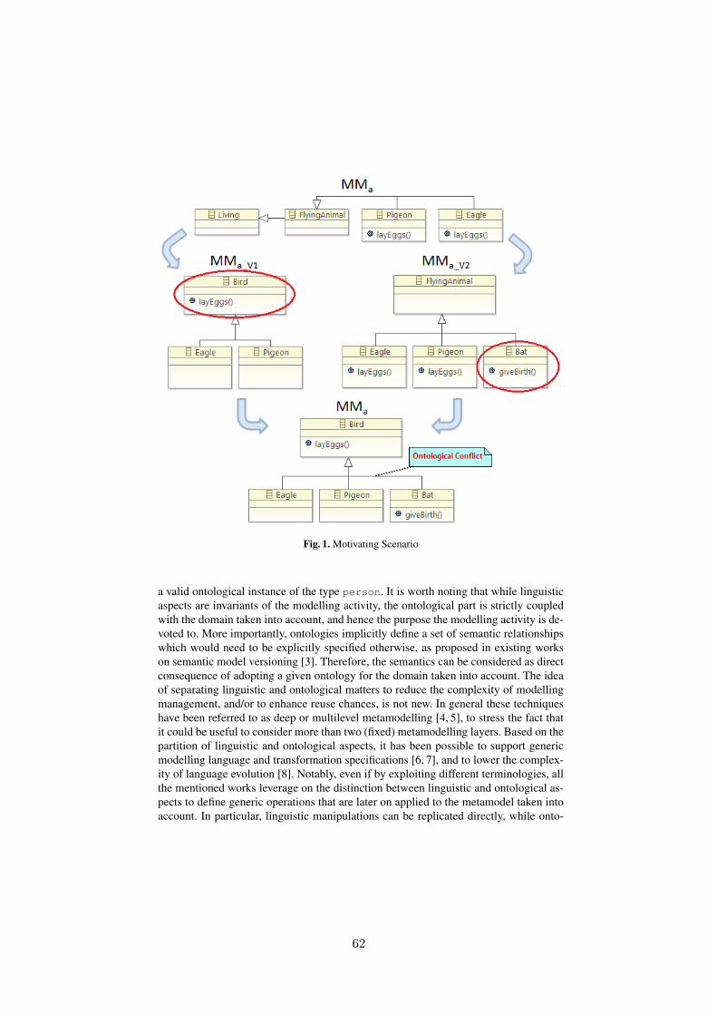
3
Fig. 1. Motivating Scenario
a valid ontological instance of the type person. It is worth noting that while linguisticaspects are invariants of the modelling activity, the ontological part is strictly coupledwith the domain taken into account, and hence the purpose the modelling activity is de-voted to. More importantly, ontologies implicitly define a set of semantic relationshipswhich would need to be explicitly specified otherwise, as proposed in existing workson semantic model versioning [3]. Therefore, the semantics can be considered as directconsequence of adopting a given ontology for the domain taken into account. The ideaof separating linguistic and ontological matters to reduce the complexity of modellingmanagement, and/or to enhance reuse chances, is not new. In general these techniqueshave been referred to as deep or multilevel metamodelling [4, 5], to stress the fact thatit could be useful to consider more than two (fixed) metamodelling layers. Based on thepartition of linguistic and ontological aspects, it has been possible to support genericmodelling language and transformation specifications [6, 7], and to lower the complex-ity of language evolution [8]. Notably, even if by exploiting different terminologies, allthe mentioned works leverage on the distinction between linguistic and ontological as-pects to define generic operations that are later on applied to the metamodel taken intoaccount. In particular, linguistic manipulations can be replicated directly, while onto-
62

4
logical ones have to be bound to the concepts pertaining to the considered applicativedomain. This allows to create operators over models, define constraints, model trans-formations, and manage the need for language evolution. In [9] this methodologicalapproach is the foundation for a framework supporting generic model management op-erators, which have been implemented within the Epsilon family of (meta-)modellinglanguages [10]. A similar solution is developed by means of the Melanie tool [11]; alsoin this case the modelling environment uses a multilevel modelling approach. More-over, the ATLAS Transformation Language has been extended to encompass predicatesdistinguishing between the various modelling levels.
Despite the growing research interest and effort in this area, so far there has beenlittle effort in the definition of evolution management support based on the separationbetween linguistic and ontological aspects. In this respect, with this paper we proposeto revisit the main model versioning features in terms of such a separation to improvetheir efficacy. In order to better grasp the potentials of this idea, in Fig. 1 a sample evo-lutionary scenario is depicted. Metamodel MMa defines a language for the definition ofliving creatures with focus on flying animals. As it can be noticed in its original formthe metaclass FlyingAnimal is specialised by the sub-types Eagle and Pigeon, bothcontaining a layEggs operation. Let us now suppose that MMa is exposed, and concur-rently evolves, in two different views, resulting in two versions of MMa, namely MMa V 1
and MMa V 2. Both view-specific metamodels undergo modifications. In case of MMa V 1,the metaclass FlyingAnimal is renamed to Bird and the operation layEggs is movedfrom the sub-types to the super-type. In MMa V 2, the new sub-type Bat is added togetherwith its operation giveBirth as specialisation of FlyingAnimal. These modifica-tions result in an ontological conflict from the perspective of MMa, since a bat is botha living creature and a flying animal giving birth to live young but NOT a bird layingeggs.
3 A Research Agenda
In the latest years a considerable research work has been devoted to all the activitiesinvolved in evolution management, notably model differencing, conflict management,as well as metamodel evolution and model co-evolution. Providing a survey on all thoseinvestigations goes far beyond the scope of this work, however in the next sections weoutline some common principles and problems characterizing the current available so-lutions. In general current approaches for model versioning that can be found in theliterature have to fight intrinsic semantics issues entailed by the modelling level of ab-straction.
This paper aims at providing the guidelines for a novel version management method-ology that takes into consideration the separation between linguistic and ontological as-pects involved in modelling activities. Our belief is that, by means of such a separation,domain-specific issues can be better managed thus improving degree of automation andaccuracy of current version management. In this respect, the next sections also illus-trate a research agenda to revisit current versioning solutions based on the separationbetween linguistic and ontological aspects, discussing foreseeable benefits and needs.
63

5
At this point, it is worth noting that this proposal is not excluding the current avail-able techniques, whereas it provides additional means to better exploit those solutions.By embracing the MDE principles, versioning artefacts are models conforming to cor-responding metamodels and are manipulated by means of model transformations [2]. Inthis respect, this work relies on a model-based representation of differences as the onesproposed in [12, 13]. In particular, we exploit the difference representation proposalin [12] because of its generative approach that allows to adapt the already existing so-lutions to our separation in a smooth way.
The general approach we pursue is composed by two main constituents, a genericmechanism tackling the structural part and its evolution, and a domain-specific spe-cialization that is bound to the ontology taken into account. As a consequence, generalevolution patterns are described in linguistic terms, while ontological information isexploited to refine their management.
3.1 Model Differencing
Model differencing has been firstly addressed by means of language-specific solutionsand then generalized to language-agnostic cases. Typically, difference detection, repre-sentation, and visualisation are performed at model level of abstraction for being ableto grasp user’s intentions [14, 15]. State-based techniques deduce modification opera-tions based on the old and new state of a model [16]. The element matching can resultvery complex and hard to make arbitrarily precise, since it is reduced to the graphhomomorphism problem [17]. A way to reduce such an inherent intricacy is to adoptoperation-based approaches which keep track of the operations performed by the usersto modify the model [18]. The drawback of such approaches is that the differences de-tection is tightly coupled to the tool, since anything happening outside the tool cannotbe tracked in terms of evolution information.
Regardless being state- or operation-based, differencing approaches rely on struc-tural similarities to determine evolution operations, thus requiring user interventionwhenever the semantics involved in the changes is misinterpreted or cannot be graspedat all. Notably, if we consider the example shown in Fig. 1, a differencing engine woulddetect a rename of the FlyingAnimal class towards Bird since their subgraphs arematching from a structural perspective. However, this information does not provide anyadditional detail about the domain-specific consequences of such a modification.
In our vision, we propose to exploit ontological information as part of the differenc-ing detection and result. By adopting a model-based mechanism like the one proposedin [12], each metaclass of the structural part involved in the modelling activity can beextended with corresponding evolution means as shown in part Figure 2.A. In this way,we are able to express the generic concepts for model evolution without coupling this in-formation with domain-specific details. In relation to the scenario depicted in Fig. 1, thestructural differencing would detect the addition of a class named Bat together with itsoperation giveBirth (see Figure 2.B). Analogously, the renaming of FlyingAnimalto Bird would be detected as shown in the upper part of Figure 2.C. On the contrary, themoving of the layEggs operation would be represented as a simple deletion in Pigeonand Eagle classes and as an addition in the Bird class (central and bottom parts of Fig-
64
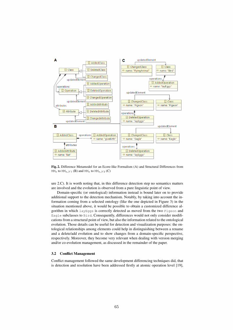
6
Fig. 2. Difference Metamodel for an Ecore-like Formalism (A) and Structural Differences fromMMa to MMa V 1 (B) and MMa to MMa V 2 (C)
ure 2.C). It is worth noting that, in this difference detection step no semantics mattersare involved and the evolution is observed from a pure linguistic point of view.
Domain-specific (or ontological) information instead is bound later on to provideadditional support to the detection mechanism. Notably, by taking into account the in-formation coming from a selected ontology (like the one depicted in Figure 3) in thesituation mentioned above, it would be possible to obtain a customized difference al-gorithm in which layEggs is correctly detected as moved from the two Pigeon andEagle subclasses to Bird. Consequently, differences would not only consider modifi-cations from a structural point of view, but also the information related to the ontologicalevolution. Those details can be useful for detection and visualization purposes: the on-tological relationships among elements could help in distinguishing between a renameand a delete/add evolution and to show changes from a domain-specific perspective,respectively. Moreover, they become very relevant when dealing with version mergingand/or co-evolution management, as discussed in the remainder of the paper.
3.2 Conflict Management
Conflict management followed the same development differencing techniques did, thatis detection and resolution have been addressed firstly at atomic operation level [19],
65
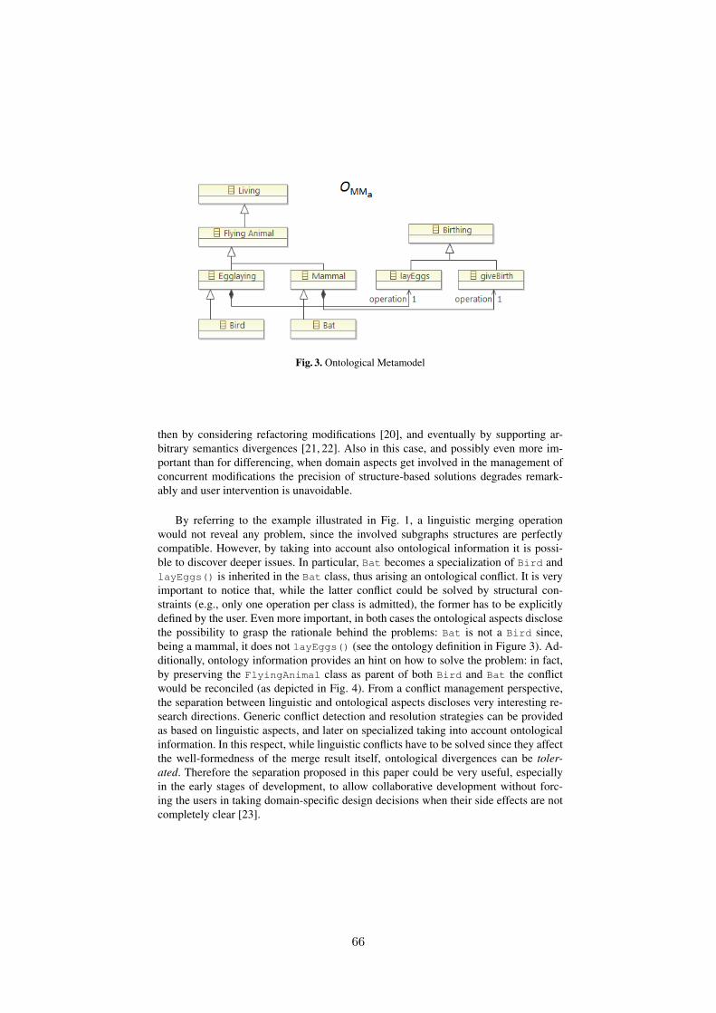
7
Fig. 3. Ontological Metamodel
then by considering refactoring modifications [20], and eventually by supporting ar-bitrary semantics divergences [21, 22]. Also in this case, and possibly even more im-portant than for differencing, when domain aspects get involved in the management ofconcurrent modifications the precision of structure-based solutions degrades remark-ably and user intervention is unavoidable.
By referring to the example illustrated in Fig. 1, a linguistic merging operationwould not reveal any problem, since the involved subgraphs structures are perfectlycompatible. However, by taking into account also ontological information it is possi-ble to discover deeper issues. In particular, Bat becomes a specialization of Bird andlayEggs() is inherited in the Bat class, thus arising an ontological conflict. It is veryimportant to notice that, while the latter conflict could be solved by structural con-straints (e.g., only one operation per class is admitted), the former has to be explicitlydefined by the user. Even more important, in both cases the ontological aspects disclosethe possibility to grasp the rationale behind the problems: Bat is not a Bird since,being a mammal, it does not layEggs() (see the ontology definition in Figure 3). Ad-ditionally, ontology information provides an hint on how to solve the problem: in fact,by preserving the FlyingAnimal class as parent of both Bird and Bat the conflictwould be reconciled (as depicted in Fig. 4). From a conflict management perspective,the separation between linguistic and ontological aspects discloses very interesting re-search directions. Generic conflict detection and resolution strategies can be providedas based on linguistic aspects, and later on specialized taking into account ontologicalinformation. In this respect, while linguistic conflicts have to be solved since they affectthe well-formedness of the merge result itself, ontological divergences can be toler-ated. Therefore the separation proposed in this paper could be very useful, especiallyin the early stages of development, to allow collaborative development without forc-ing the users in taking domain-specific design decisions when their side effects are notcompletely clear [23].
66
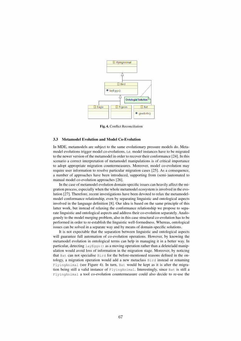
8
Fig. 4. Conflict Reconciliation
3.3 Metamodel Evolution and Model Co-Evolution
In MDE, metamodels are subject to the same evolutionary pressure models do. Meta-model evolutions trigger model co-evolutions, i.e. model instances have to be migratedto the newer version of the metamodel in order to recover their conformance [24]. In thisscenario a correct interpretation of metamodel manipulations is of critical importanceto adopt appropriate migration countermeasures. Moreover, model co-evolution mayrequire user information to resolve particular migration cases [25]. As a consequence,a number of approaches have been introduced, supporting from (semi-)automated tomanual model co-evolution approaches [26].
In the case of metamodel evolution domain-specific issues can heavily affect the mi-gration process, especially when the whole metamodel ecosystem is involved in the evo-lution [27]. Therefore, recent investigations have been devoted to relax the metamodel-model conformance relationship, even by separating linguistic and ontological aspectsinvolved in the language definition [8]. Our idea is based on the same principle of thislatter work, but instead of relaxing the conformance relationship we propose to sepa-rate linguistic and ontological aspects and address their co-evolution separately. Analo-gously to the model merging problem, also in this case structural co-evolution has to beperformed in order to re-establish the linguistic well-formedness. Whereas, ontologicalissues can be solved in a separate way and by means of domain-specific solutions.
It is not expectable that the separation between linguistic and ontological aspectswill guarantee full automation of co-evolution operations. However, by knowing themetamodel evolution in ontological terms can help in managing it in a better way. Inparticular, detecting layEggs() as a moving operation rather than a delete/add manip-ulation would avoid loss of information in the migration stage. Moreover, by noticingthat Bat can not specialise Bird for the before-mentioned reasons defined in the on-tology, a migration operation would add a new metaclass Bird instead or renamingFlyingAnimal (see Figure 4). In turn, Bat would be kept as it is after the migra-tion being still a valid instance of FlyingAnimal. Interestingly, since Bat is still aFlyingAnimal a tool co-evolution countermeasure could also decide to re-use the
67
9
same icon, or ask for a new one specific for bats. In the same way, it could be pos-sible to notice that using the Bird icon would be erroneous from a domain semanticsperspective.
4 Outlook
This paper proposed the guidelines for a novel model versioning methodology basedon the separation between linguistic and ontological aspects of (meta-)modelling. Theidea is not ignoring what already existing and developed in the latest years for modelevolution investigations; rather, it aims at enriching current solutions by adding onto-logical details to the manipulation information. In this respect, we remark once againthat current semantics aware versioning solutions do not aim at the clear separationbetween structural and ontological aspects, which typically get intertwined in the meta-model definition. Moreover, we consider the ontological part as domain information tobe plugged-in in the generic version management mechanism. Such approach allowsto build-up generic differencing, merging, and co-evolution techniques, taking into ac-count ontological information as a refinement step.
Up to now, it has been possible to conduct small experiments by means of alreadyavailable techniques (notably [12] and the Melanie tool [11]) and the results are en-couraging. However, the methodology has to be validated against real-life systems toprove its efficacy. Moreover, it is not possible to exclude future needs for addressingontological-specific evolutions, both for the detection, representation, and management,beyond the general additions, deletions, and changes.
References
1. Kuhne, T.: Matters of (meta-)modeling. SoSym 5 (2006) 369–3852. Bezivin, J.: On the Unification Power of Models. SoSym 4 (2005) 171–1883. Kappel, G., Kapsammer, E., Kargl, H., Kramler, G., Reiter, T., Retschitzegger, W.,
Schwinger, W., Wimmer, M.: Lifting metamodels to ontologies: A step to the semanticintegration of modeling languages. In: Procs. of MoDELS, Genova (Italy). LNCS, Springer(2006) 528–542
4. de Lara, J., Guerra, E.: Deep Meta-modelling with MetaDepth. In: Proc. of TOOLS, Malaga(Spain). LNCS (2010) 1–20
5. Atkinson, C., Gutheil, M., Kennel, B.: A Flexible Infrastructure for Multilevel LanguageEngineering. IEEE TSE 35 (2009) 742–755
6. de Lara, J., Guerra, E., Cuadrado, J.S.: Abstracting Modelling Languages: A ReutilizationApproach. In: Proc. of CAiSE, Gdansk (Poland). LNCS, Springer (2012) 127–143
7. Cuadrado, J.S., Guerra, E., de Lara, J.: Generic Model Transformations: Write Once, ReuseEverywhere. In: Procs. ICMT, Zurich (Switzerland), 2011. LNCS, Springer (2011) 62–77
8. Gomez, P., Sanchez, M., Florez, H., Villalobos, J.: Co-creation of models and metamodelsfor enterprise architecture projects. In: Procs. of XM, ACM (2012) 21–26
9. Rose, L.M., Guerra, E., de Lara, J., Etien, A., Kolovos, D.S., Paige, R.F.: Genericity formodel management operations. SoSym 12 (2013) 201–219
10. : Epsilon. http://www.eclipse.org/epsilon/ (2013)11. : Melanie - multi-level modeling and ontology engineering environment.
http://code.google.com/a/eclipselabs.org/p/melanie/ (2013)
68
10
12. Cicchetti, A., Di Ruscio, D., Pierantonio, A.: A Metamodel Independent Approach to Dif-ference Representation. JOT 6 (2007) 165–185
13. Rivera, J., Vallecillo, A.: Representing and Operating with Model Differences. In: Procs.TOOLS EUROPE. (2008)
14. Kolovos, D., Paige, R., Polack, F.: Model comparison: a foundation for model compositionand model transformation testing. In: Procs. GaMMa, Shanghai (China). (2006) 13–20
15. Brun, C., Pierantonio, A.: Model Differences in the Eclipse Modeling Framework. UP-GRADE, The European Journal for the Informatics Professional (2008)
16. Conradi, R., Westfechtel, B.: Version Models for Software Configuration Management.ACM Computing Surveys 30 (1998) 232–282
17. Kolovos, D.S., Di Ruscio, D., Paige, R.F., Pierantonio, A.: Different models for modelmatching: An analysis of approaches to support model differencing. In: Proc. 2nd CVSM’09,ICSE09 Workshop, Vancouver, Canada (2009)
18. Mens, T.: A State-of-the-Art Survey on Software Merging. IEEE Trans. Softw. Eng. 28(2002) 449–462
19. Alanen, M., Porres, I.: Difference and Union of Models. In: UML 2003 - The UnifiedModeling Language. Volume 2863 of LNCS., Springer-Verlag (2003) 2–17
20. Mens, T., Taentzer, G., Runge, O.: Detecting Structural Refactoring Conflicts Using CriticalPair Analysis. Electr. Notes Theor. Comput. Sci 127 (2005) 113–128
21. Altmanninger, K., Seidl, M., Wimmer, M.: A survey on model versioning approaches. In-ternational Journal of Web Information Systems (IJWIS) 5 (2009) 271 – 304
22. Cicchetti, A., Di Ruscio, D., Pierantonio, A.: Managing Model Conflicts in DistributedDevelopment. In: Procs. MoDELS. (2008) 311–325
23. Wieland, K., Langer, P., Seidl, M., Wimmer, M., Kappel, G.: Turning conflicts into collabo-ration. Computer Supported Cooperative Work 22 (2013) 181–240
24. Sendall, S., Kozaczynski, W.: Model Transformation: The Heart and Soul of Model-DrivenSoftware Development. IEEE Software 20 (2003) 42–45
25. Gruschko, B., Kolovos, D., Paige., R.: Towards Synchronizing Models with Evolving Meta-models. In: Procs of the Work. MODSE. (2007)
26. Rose, L.M., Herrmannsdoerfer, M., Williams, J.R., Kolovos, D.S., Garces, K., Paige, R.F.,Polack, F.A.C.: A Comparison of Model Migration Tools. In: Procs. MoDELS. LNCS,Springer (2010) 61–75
27. Iovino, L., Pierantonio, A., Malavolta, I.: On the impact significance of metamodel evolutionin mde. Journal of Object Technology 11 (2012) 3: 1–33
69

Analyzing Behavioral Refactoring of ClassModels
Wuliang Sun, Robert B. France, Indrakshi Ray
Colorado State University, Fort Collins, USA
Abstract. Software modelers refactor their design models to improvedesign quality while preserving essential functional properties. Tools thatallow modelers to check whether their refactorings preserve specified es-sential behaviors are needed to support rigorous model evolution. In thispaper we describe a rigorous approach to analyzing design model refac-torings that involve changes to operation specifications expressed in theObject Constraint Language (OCL). The analysis checks whether therefactored model preserves the essential behavior of changed operationsin a source design model. A refactoring example involving the AbstractFactory design pattern is used in the paper to illustrate the approach.Keywords:Behavioral refactoring, UML/OCL, Alloy
1 Introduction
In Model-Driven Development (MDD) projects, one can expect design modelsto evolve as developers explore design spaces for high quality solutions. Classmodels are among the most popular models used in practice and given theirpivotal roles, there is a need to manage their evolution. Software refactoring[4][14] is an important class of changes that is applicable to class models. Thegoal of a refactoring is to improve software qualities such as maintainabilityand extensibility, while preserving essential structural and behavioral proper-ties. A number of model refactoring mechanisms have been proposed (e.g., see[2][5][12][19][20][21]), and many (e.g., see [19][21]) provide support for checkingwhether structural properties are preserved in refactored models. However, weare not aware of any approach that supports rigorous analysis of behavioralproperties when operation specifications in class models are added, removed, ormodified. In this paper we describe a rigorous approach to analyzing the refac-toring of design class models that involve changes to operation specificationsexpressed in the Object Constraint Language (OCL) [15].
The model on which a refactoring is performed is called the source model,and the model produced by the refactoring is called the refactored model. Arefactoring that involves making changes to operation specifications is calleda behavioral refactoring. In this paper, we present an approach to analyzingbehavioral refactorings to check that changes to operation specifications preservethe net effect of the operation (i.e., its essential behavior) as specified in thesource model. The net effect of an operation can be expressed using the OCLpre-/post-conditions.
70
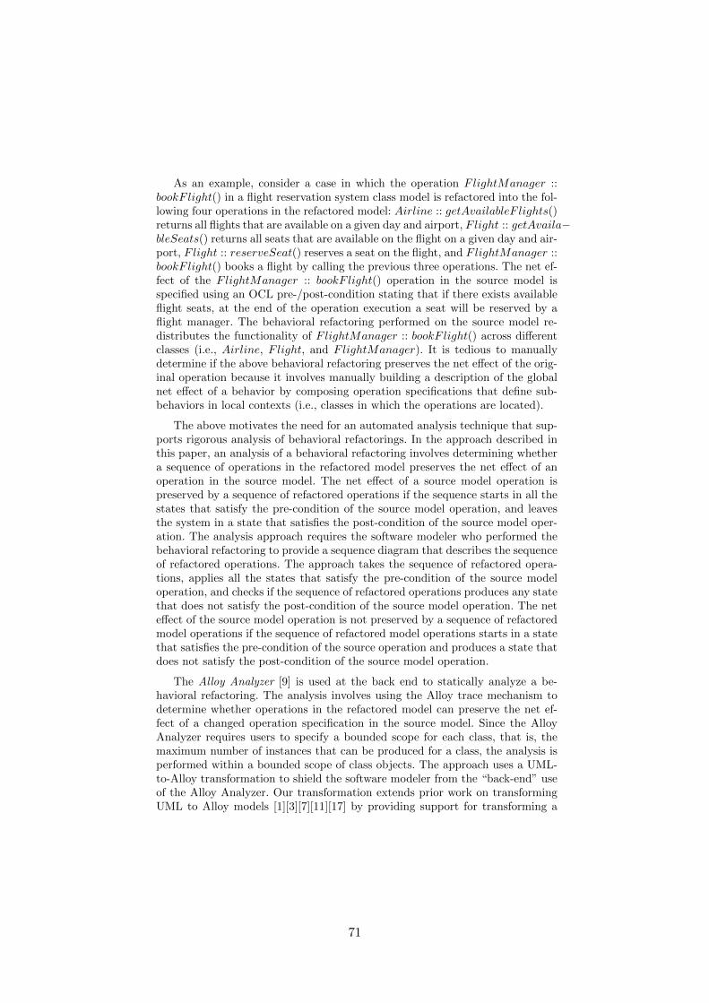
As an example, consider a case in which the operation FlightManager ::bookF light() in a flight reservation system class model is refactored into the fol-lowing four operations in the refactored model: Airline :: getAvailableF lights()returns all flights that are available on a given day and airport, Flight :: getAvaila−bleSeats() returns all seats that are available on the flight on a given day and air-port, Flight :: reserveSeat() reserves a seat on the flight, and FlightManager ::bookF light() books a flight by calling the previous three operations. The net ef-fect of the FlightManager :: bookF light() operation in the source model isspecified using an OCL pre-/post-condition stating that if there exists availableflight seats, at the end of the operation execution a seat will be reserved by aflight manager. The behavioral refactoring performed on the source model re-distributes the functionality of FlightManager :: bookF light() across differentclasses (i.e., Airline, Flight, and FlightManager). It is tedious to manuallydetermine if the above behavioral refactoring preserves the net effect of the orig-inal operation because it involves manually building a description of the globalnet effect of a behavior by composing operation specifications that define sub-behaviors in local contexts (i.e., classes in which the operations are located).
The above motivates the need for an automated analysis technique that sup-ports rigorous analysis of behavioral refactorings. In the approach described inthis paper, an analysis of a behavioral refactoring involves determining whethera sequence of operations in the refactored model preserves the net effect of anoperation in the source model. The net effect of a source model operation ispreserved by a sequence of refactored operations if the sequence starts in all thestates that satisfy the pre-condition of the source model operation, and leavesthe system in a state that satisfies the post-condition of the source model oper-ation. The analysis approach requires the software modeler who performed thebehavioral refactoring to provide a sequence diagram that describes the sequenceof refactored operations. The approach takes the sequence of refactored opera-tions, applies all the states that satisfy the pre-condition of the source modeloperation, and checks if the sequence of refactored operations produces any statethat does not satisfy the post-condition of the source model operation. The neteffect of the source model operation is not preserved by a sequence of refactoredmodel operations if the sequence of refactored model operations starts in a statethat satisfies the pre-condition of the source operation and produces a state thatdoes not satisfy the post-condition of the source model operation.
The Alloy Analyzer [9] is used at the back end to statically analyze a be-havioral refactoring. The analysis involves using the Alloy trace mechanism todetermine whether operations in the refactored model can preserve the net ef-fect of a changed operation specification in the source model. Since the AlloyAnalyzer requires users to specify a bounded scope for each class, that is, themaximum number of instances that can be produced for a class, the analysis isperformed within a bounded scope of class objects. The approach uses a UML-to-Alloy transformation to shield the software modeler from the “back-end” useof the Alloy Analyzer. Our transformation extends prior work on transformingUML to Alloy models [1][3][7][11][17] by providing support for transforming a
71
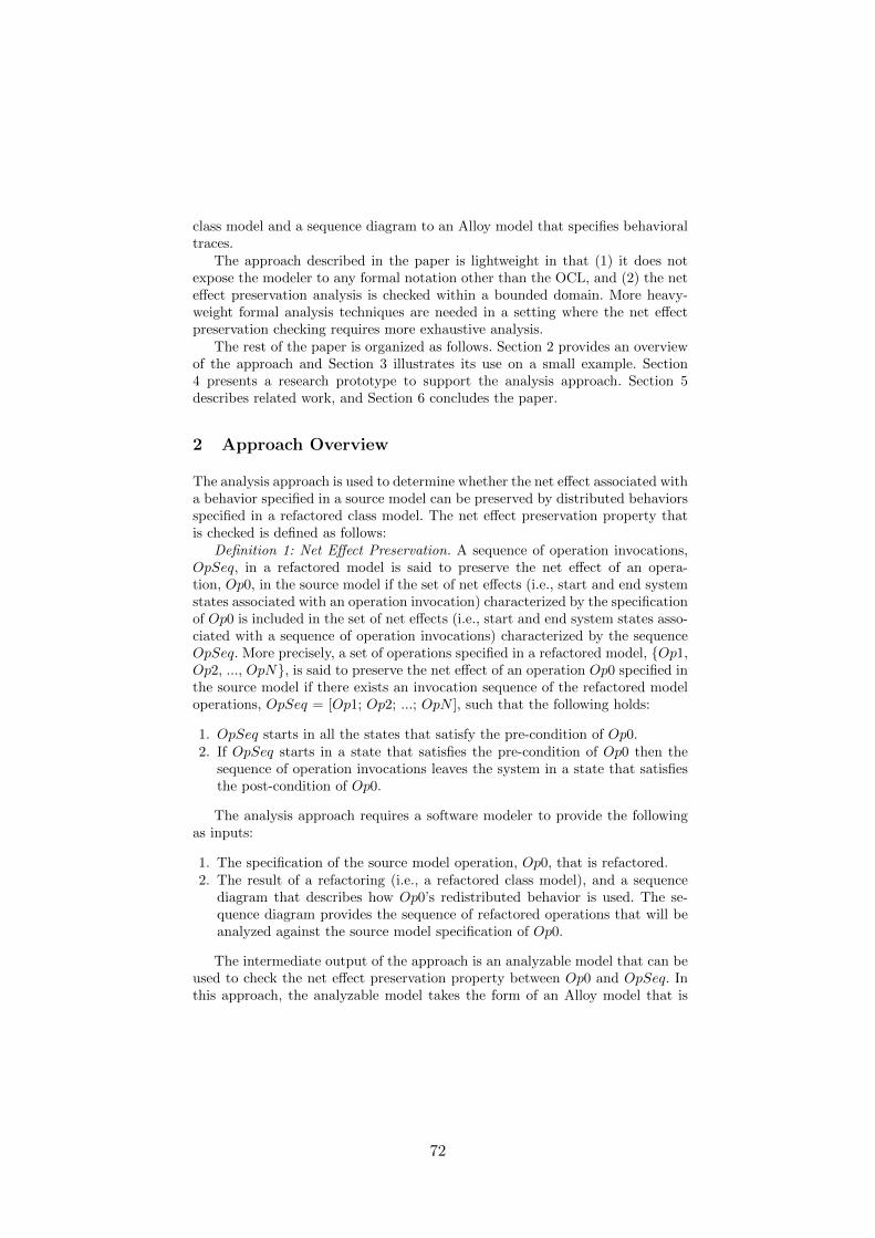
class model and a sequence diagram to an Alloy model that specifies behavioraltraces.
The approach described in the paper is lightweight in that (1) it does notexpose the modeler to any formal notation other than the OCL, and (2) the neteffect preservation analysis is checked within a bounded domain. More heavy-weight formal analysis techniques are needed in a setting where the net effectpreservation checking requires more exhaustive analysis.
The rest of the paper is organized as follows. Section 2 provides an overviewof the approach and Section 3 illustrates its use on a small example. Section4 presents a research prototype to support the analysis approach. Section 5describes related work, and Section 6 concludes the paper.
2 Approach Overview
The analysis approach is used to determine whether the net effect associated witha behavior specified in a source model can be preserved by distributed behaviorsspecified in a refactored class model. The net effect preservation property thatis checked is defined as follows:
Definition 1: Net Effect Preservation. A sequence of operation invocations,OpSeq, in a refactored model is said to preserve the net effect of an opera-tion, Op0, in the source model if the set of net effects (i.e., start and end systemstates associated with an operation invocation) characterized by the specificationof Op0 is included in the set of net effects (i.e., start and end system states asso-ciated with a sequence of operation invocations) characterized by the sequenceOpSeq. More precisely, a set of operations specified in a refactored model, {Op1,Op2, ..., OpN}, is said to preserve the net effect of an operation Op0 specified inthe source model if there exists an invocation sequence of the refactored modeloperations, OpSeq = [Op1; Op2; ...; OpN ], such that the following holds:
1. OpSeq starts in all the states that satisfy the pre-condition of Op0.2. If OpSeq starts in a state that satisfies the pre-condition of Op0 then the
sequence of operation invocations leaves the system in a state that satisfiesthe post-condition of Op0.
The analysis approach requires a software modeler to provide the followingas inputs:
1. The specification of the source model operation, Op0, that is refactored.2. The result of a refactoring (i.e., a refactored class model), and a sequence
diagram that describes how Op0’s redistributed behavior is used. The se-quence diagram provides the sequence of refactored operations that will beanalyzed against the source model specification of Op0.
The intermediate output of the approach is an analyzable model that can beused to check the net effect preservation property between Op0 and OpSeq. Inthis approach, the analyzable model takes the form of an Alloy model that is
72

produced from (1) the refactored class model, and (2) a sequence diagram thatdescribes OpSeq.
The specifications for Op0 and the operations involved in OpSeq are alsoincluded in the Alloy model. The inclusion of Op0 in an Alloy model producedfrom the refactored class model can be problematic when Op0 refers to elementsnot included in the refactored model. For this reason the first step of the ap-proach checks that the elements referenced in the Op0 operation specificationalso appear in the refactored model.
The second step of the approach generates the base Alloy model that isextended in following steps to check the preservation property. We use a UML-to-Alloy transformation that builds upon our previous work on rigorous analysisof UML class models [17].
The third step of the approach takes as input the specification of Op0 anda sequence diagram, and produces an Alloy assertion (or predicate) that is usedto determine whether the sequence described in the sequence diagram (OpSeq)preserves the net effect of Op0. The assertion (or predicate) is added to the Alloymodel generated in the second step of the approach. If a check of the assertion(or predicate) by the Alloy Analyzer produces an Alloy instance then the neteffect specified by Op0 cannot be preserved by the operation sequence.
More details on the major steps of the approach can be found in [18].
3 An Illustrating Example
A maze game class model from [6] (see Figure 1) is used in this paper to illustratethe analysis approach. The MazeGame class is responsible for creating differenttypes of mazes (e.g., BombedMaze and EnchantedMaze) and their parts (e.g.,RoomWithBomb and EnchantedRoom). A maze room consists of four sidesthat can be doors, walls, or other rooms.
The operation createBombedMaze() in class MazeGame is used to create abombed maze that consists of four walls. Its net effect in the form of OCL spec-ification is given below:
Context MazeGame::createBombedMaze() : BombedMaze// Pre-condition: no maze has been createdPre: self.maze→isEmpty()// Post-condition: a bombed maze has been created, and it includes a room// with four wallsPost: result.oclIsNew() and self.maze.bRooms→size() = 1 andself.maze.bRooms→forAll(r : RoomWithBomb | r.bwalls→size() = 4)
If a new type of maze, maze room, door or wall were added, the structure of theclass model would need to be changed significantly. Incorporating the AbstractFactory pattern [6] into the class model results in a more flexible design in whichthe maze creation responsibilities are localized in factories that the MazeGameclass can access.
73
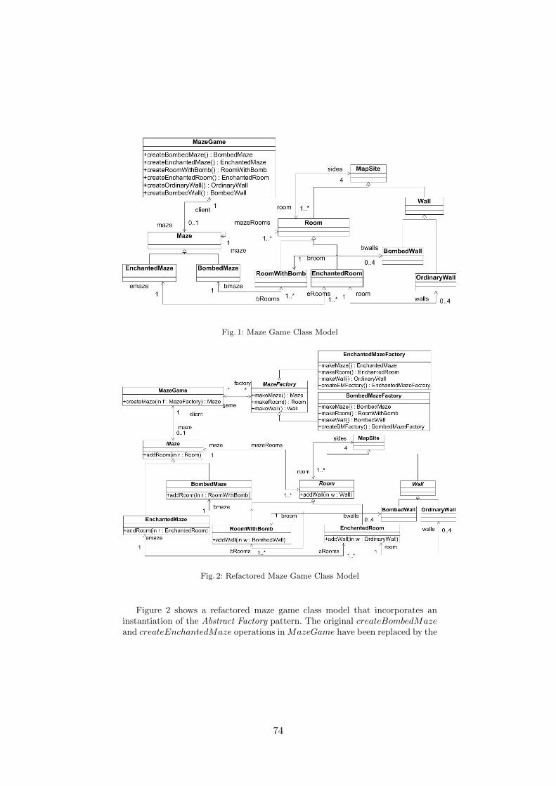
Fig. 1: Maze Game Class Model
Fig. 2: Refactored Maze Game Class Model
Figure 2 shows a refactored maze game class model that incorporates aninstantiation of the Abstract Factory pattern. The original createBombedMazeand createEnchantedMaze operations inMazeGame have been replaced by the
74

createMaze(f : MazeFactory) : Maze operation, that uses a factory to createa specific type of maze. The net effects of the original operations in MazeGameneed to be preserved by the behavioral refactoring. The analysis approach de-scribed in this paper can be used to check if the net effect of createBombedMazeis preserved by relevant operations in the refactored model.
The OCL specifications for createMaze and addRoom are given below:
Context MazeGame::createMaze(f:MazeFactory) : Maze// Pre-condition: a maze factory has been associated with a maze gamePre: self.factory→includes(f)Post: true
Context Maze::addRoom(r:Room)// Pre-condition: a room has not been associated with a mazePre: self.mazeRooms→excludes(r)// Post-condition: a room has been associated with a mazePost: self.mazeRooms→includes(r)
Unlike the createBombedMaze operation, the createMaze operation dele-gates its responsibility to other operations (i.e.,makeMaze,makeRoom, addRo-om, makeWall, and addWall) in the refactored class model. Due to space lim-itations, only the specifications of createMaze and addRoom are given in thepaper (see above). More operation specifications can be found in [18]. A sequencediagram (see Figure 3) is used to describe the result of the behavioral refactor-ing. It describes an invocation sequence of the refactored model operations thatis intended to preserve the net effect of the createBombedMaze operation in thesource model.
The analysis showed that if we removed an operation (e.g., addRoom) fromthe operation sequence in Fig. 3, the net effect of createBombedMaze cannot bepreserved by the rest of operations in Fig. 3. We also used the same analysis ap-proach to check if the net effects of other source model operations are preservedby refactored model operations. Our analysis results showed that all the opera-tions in the source model (e.g., createEnchantedMaze, createRoomWithBomb,createEnchantedRoom, createOrdinaryWall and createBombedWall) can bepreserved by relevant operations in the refactored model.
4 Tool Support
We developed a research prototype to investigate the feasibility of developing toolsupport for the approach. The prototype consists of an Eclipse OCL parser, anEcore/OCL transformer and an Alloy Analyzer. The Ecore/OCL transformer isdeveloped using Kermeta [13], an aspect-oriented metamodeling tool. The inputsof the prototype are (1) an EMF Ecore [16] file that specifies a refactored classmodel, (2) a textual OCL file that specifies the pre-/post-conditions of Op0 and
75
Fig. 3: A Sequence Diagram that Describes an Invocation Sequence of the RefactoredModel Operations
operations involved in OpSeq, and (3) a textual file that describes a sequencediagram.
The inputs are automatically transformed to an Alloy model consisting ofsignatures and predicates. The prototype then uses the APIs provided by theAlloy Analyzer to pass the Alloy model to the Alloy SAT solver. The resultreturned by the Alloy SAT solver is interpreted by the prototype. The interpretedresult provides the net effect preservation property between Op0 and OpSeq.
The prototype implementation uses a visitor pattern to transform a classmodel with operation specifications into an Alloy model. The traditional vis-itor design pattern keeps the separation of the structure (i.e., the metamodelelements) and the behavior (i.e., the visitor) by using a specific class for thevisitor, and thus results in ping-pong calls between the objects of the structureand the objects of the visitor. The Kermeta [10] language provides an aspectweaving mechanism to simplify the visitor pattern by allowing a user to definea visit method for each model element being visited in an aspect class that is
76

woven into an existing base class at runtime. There is thus no need to keep avisitor class that is used to traverse each model element of a metamodel.
5 Related Work
Two broad categories of related work are discussed in the section: work on modelrefactoring and work on UML-to-Alloy transformation.
5.1 Model Refactoring
Refactoring has attracted much attention from the MDE community since itwas first introduced by Opdyke in his PhD dissertation [14]. Boger et al. [2]applied the idea of refactoring to UML class diagrams, statechart diagrams,and activity diagrams. Their approach, however, does not provide support forrigorously reasoning about a behavioral refactoring.
Both Sunye et al. [19] and Van Gorp et al. [21] used OCL to formally specifythe refactoring for UML models. An operation is defined for each type of therefactoring and its OCL pre-/post-condition specifies the model structure thatmust be satisfied before and after the refactoring associated with the operation.Their approach, however, can only be used to verify the refactoring involvingthe changes to model structures.
France et al. [5] described a metamodeling approach to pattern-based modelrefactoring in which refactorings are used to introduce a new design pattern in-stance to the model. Mens and Tourwe [12] used logic reasoning to detect if adesign pattern instance that is introduced to a class model, limits the applica-bility of certain refactorings.
Straeten et al. [20] proposed a behavior preserving refactoring approach forUML class models. Unlike our approach, the behavior of a class model in theirapproach is expressed using state machines and sequence diagrams. Gheyi et al.[8] described a rigorous approach to verifying the refactoring for Alloy models.
However, based on our knowledge, none of the above approaches can be usedto analyze operation-based model refactoring that involves changes to operationspecifications.
5.2 UML to Alloy Transformation
Georg et al. [7] used both Alloy and UML/OCL to specify the runtime config-uration management of a distributed system. An ad-hoc comparison betweenAlloy and UML/OCL is discussed in their paper.
Dennis et al. [3] used the Alloy Analyzer to uncover the errors in a UMLmodel of a radiation therapy machine. The operations in the design model arespecified using OCL. An informal description of OCL-to-Alloy transformation isdescribed in their approach. Their approach, however, does not provide supportfor automated transformation between UML/OCL and Alloy.
77
Anastasakis et al. [1] described a tool, namely UML2Alloy, that automati-cally transforms a UML class model with OCL invariants into an Alloy model.Their tool builds upon a formal mapping between UML/OCL metamodel andAlloy metamodel. Unlike their approach, our approach leverages Alloy’s tracemechanism to generate an Alloy model with trace features from a UML/OCLmodel.
Maoz et al. [11] developed a tool that implements the transformation betweenUML class models and Alloy models. Unlike the approach described in [1], Maoz’stool produces a single Alloy module from two class models. Maoz’s approach,however, does not provide support for class models with OCL invariants andoperation specifications.
6 Conclusion
We presented an approach to rigorously analyzing a behavioral refactoring thatinvolves making changes to operation specifications expressed in the OCL. Thebehavioral refactoring analysis involves checking whether relevant operations inthe refactored model can preserve the net effects of the operations targeted bythe refactoring in the source model. The net effect preservation checking tech-nique described in the paper builds upon the Alloy Analyzer and thus requiresa translation from UML class models and OCL operation specifications to Alloymodels. We developed a prototype for transforming UML+OCL models to Al-loy models with traces to support the net effect preservation check. We appliedthe approach to a pattern-based model refactoring to demonstrate how softwaremodelers can use the approach to analyze a behavioral refactoring.
We plan to extend the behavioral refactoring analysis approach by providingsupport for more complex OCL operators. Specifically we are currently inves-tigating how we can use SMT solvers (e.g., Microsoft Z3) at the back-end toanalyze the OCL specifications. Our future work will also explore how mappingsbetween equivalent source and refactored forms can be used to support the neteffect preservation checking.
ACKNOWLEDGMENT
The work described in this report was supported by the National Science Foun-dation grant CCF-1018711.
References
1. K. Anastasakis, B. Bordbar, G. Georg, and I. Ray. On challenges of model trans-formation from UML to Alloy. Software and Systems Modeling, 9(1):69–86, 2010.
2. M. Boger, T. Sturm, and P. Fragemann. Refactoring browser for UML. Objects,Components, Architectures, Services, and Applications for a Networked World,pages 366–377, 2003.
78

3. G. Dennis, R. Seater, D. Rayside, and D. Jackson. Automating commutativityanalysis at the design level. In ACM SIGSOFT Software Engineering Notes, vol-ume 29, pages 165–174. ACM, 2004.
4. M. Fowler and K. Beck. Refactoring: improving the design of existing code.Addison-Wesley Professional, 1999.
5. R. France, S. Chosh, E. Song, and D.K. Kim. A metamodeling approach to pattern-based model refactoring. Software, IEEE, 20(5):52–58, 2003.
6. E. Gamma, H. Richard, J. Ralph, and V. John. Design patterns: elements ofreusable object-oriented software. Reading: Addison Wesley Publishing Company,1995.
7. G. Georg, J. Bieman, and R. France. Using Alloy and UML/OCL to specifyrun-time configuration management: a case study. Practical UML-Based RigorousDevelopment Methods-Countering or Integrating the eXtremists, 7:128–141, 2001.
8. R. Gheyi, T. Massoni, and P. Borba. A rigorous approach for proving modelrefactorings. In Proceedings of the 20th IEEE/ACM international Conference onAutomated software engineering, pages 372–375. ACM, 2005.
9. D. Jackson. Alloy: a lightweight object modelling notation. ACM Transactions onSoftware Engineering and Methodology (TOSEM), 11(2):256–290, 2002.
10. J.M. Jezequel, O. Barais, and F. Fleurey. Model driven language engineering withkermeta. Generative and Transformational Techniques in Software EngineeringIII, pages 201–221, 2011.
11. S. Maoz, J. Ringert, and B. Rumpe. Cddiff: Semantic differencing for class dia-grams. ECOOP 2011–Object-Oriented Programming, pages 230–254, 2011.
12. T. Mens and T. Tourwe. A declarative evolution framework for object-orienteddesign patterns. In Software Maintenance, 2001. Proceedings. IEEE InternationalConference on, pages 570–579. IEEE, 2001.
13. P.A. Muller, F. Fleurey, and J.M. Jezequel. Weaving executability into object-oriented meta-languages. Model Driven Engineering Languages and Systems, pages264–278, 2005.
14. W.F. Opdyke. Refactoring: A program restructuring aid in designing object-oriented application frameworks. PhD thesis, PhD thesis, University of Illinoisat Urbana-Champaign, 1992.
15. O.M.G.A. Specification. Object constraint language, 2007.16. D. Steinberg, F. Budinsky, E. Merks, and M. Paternostro. EMF: Eclipse Modeling
Framework. Addison-Wesley Professional, 2008.17. W. Sun, R. France, and I. Ray. Rigorous analysis of UML access control policy
models. In Policies for Distributed Systems and Networks (POLICY), 2011 IEEEInternational Symposium on, pages 9–16. IEEE, 2011.
18. W. Sun, R. France, and I. Ray. Analyzing Behavioral Refactoring ofClass Models. Technical Report CS-13-104, Colorado State University,http://www.cs.colostate.edu/TechReports/, 2013.
19. G. Sunye, D. Pollet, Y. Le Traon, and J.M. Jezequel. Refactoring UML models.UML 2001The Unified Modeling Language. Modeling Languages, Concepts, andTools, pages 134–148, 2001.
20. R. Van Der Straeten, V. Jonckers, and T. Mens. A formal approach to modelrefactoring and model refinement. Software and Systems Modeling, 6(2):139–162,2007.
21. P. Van Gorp, H. Stenten, T. Mens, and S. Demeyer. Towards automating source-consistent UML refactorings. UML 2003-The Unified Modeling Language. ModelingLanguages and Applications, pages 144–158, 2003.
79
Specification of a Legacy Tool by Means of aDependency Graph to Improve its Reusability
Paola Vallejo, Mickael Kerboeuf, and Jean-Philippe Babau
University of Brest (France), Lab-STICC, MOCS Team{vallejoco,kerboeuf,babau}@univ-brest.fr
Abstract. This position paper, investigates a way to improve the reusabil-ity of legacy tools in specific contexts (defined by specific metamodels).The approach is based on a dedicated language for co-evolution, calledModif. Its associated process involves two model migrations. The firstone (Migration), allows to put data under the scope of a legacy tool.The second one (Reverse Migration), allows to put the legacy tool’s out-put back into the original specific context. The approach is generalizedby introducing the notion of dependency graph. It specifies the relationsbetween the legacy tool’s input and the legacy tool’s output. The depen-dency graph is then used to address some complexities of the ReverseMigration. The improvement is illustrated by the reuse of a flattener tooldefined on a specific metamodel of FSM (finite state machines).
Keywords: Legacy tool’s reusability, DSML, metamodel transformation, modelmigration, code generation
1 Introduction
Reuse is the act of using an asset in different systems [2]. In DSML (Domain-Specific Modeling Languages), the reuse of legacy tools reduces the cost of pro-ducing the entire tool support of a DSML. The reuse is also employed in othercontexts such as model transformations, [6] proposes reusing transformationsinstead of rewrite them.
The reuse brings up some difficulties with it; for example, when a designer isdefining specific functions for the DSML, he frequently notices that the functionsare already provided by a legacy tool. Nevertheless, they were developed for avariant of his metamodel.
In this regard, the aim of reusing, raises two questions: how the DSML modelcan be adapted to be conform to the legacy tool’s metamodel? And how theoutput of the legacy tool can be adapted in return to the DSML context?
Modif [1] [5] addresses those two questions. Figure 1 shows the operationsperformed by Modif to handle the interactions between the elements of the twocontexts (DSML and legacy tool). The DSML context’s metamodel MM, itsconforming model M1, the legacy tool context’s metamodel MM’ and the legacytool Tool are those we aim at reusing. Then, from M1, the objective is to obtainM2, M3 and M4 automatically.
80
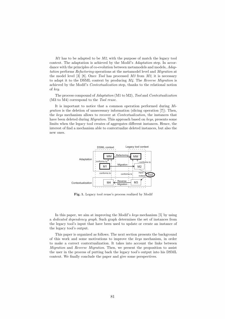
M1 has to be adapted to be M2, with the purpose of match the legacy toolcontext. The adaptation is achieved by the Modif’s Adaptation step. In accor-dance with the principles of co-evolution between metamodels and models, Adap-tation performs Refactoring operations at the metamodel level and Migration atthe model level [3] [8]. Once Tool has processed M3 from M2, it is necessaryto adapt it to the DSML context by producing M4. The Reverse Migration isachieved by the Modif’s Contextualization step, thanks to the relational notionof key.
The process compound of Adaptation (M1 to M2), Tool and Contextualization(M3 to M4) correspond to the Tool reuse.
It is important to notice that a common operation performed during Mi-gration is the deletion of unnecessary information (slicing operation [7]). Then,the keys mechanism allows to recover at Contextualization, the instances thathave been deleted during Migration. This approach based on keys, presents somelimits when the legacy tool creates of aggregates different instances. Hence, theinterest of find a mechanism able to contextualize deleted instances, but also thenew ones.
MM MM ’
M1 M2
M4 M3
Tool
Refactoring
Migration
Reverse
Migration
conforms to
conforms to conforms to
conforms to
input
output
DSML context Legacy tool context
Adaptation
Contextualization
Fig. 1. Legacy tool reuse’s process realized by Modif
In this paper, we aim at improving the Modif’s keys mechanism [5] by usinga dedicated dependency graph. Such graph determines the set of instances fromthe legacy tool’s input that have been used to update or create an instance ofthe legacy tool’s output.
This paper is organized as follows. The next section presents the backgroundof this work and some motivations to improve the keys mechanism, in orderto make a correct contextualization. It takes into account the links betweenMigration and Reverse Migration. Then, we present the proposition to assistthe user in the process of putting back the legacy tool’s output into his DSMLcontext. We finally conclude the paper and give some perspectives.
81
2 Background and Motivation
In a simple example we show the tool reuse process and why Reverse Migrationis a key problem.
Adaptation Modif’s Adaptation is based on co-evolution operators (e.g. up-date, delete) like classically proposed by [4]. A legacy tool is defined for a spe-cific usage, and its metamodel includes less concepts than a DSML metamodelproposes. Then, the most used operators for adaptation are rename and delete.
Tool The input and the output of the legacy tool Tool conform to the samemetamodel. Tool executes creation, update and deletion.
Contextualization Modif [5] proposes a keys mechanism. A key is an attributeassociated to each instance of M1 that uniquely identifies it. The keys allow tokeep a relationship between instances of M1 and those still exist in M2 and M3after Migration and Tool application. Then, M4 is built by adding M3 instancesand instances that have been deleted during Adaptation.
This is possible by applying the concept of relational natural join of rela-tional databases. The relationships between instances are also built reusing thekeys information. Thus, instances of the legacy tool’s output are reconnected tothe instances that have been recovered. New instances cannot be reconnected toother instances, and an instance of M3 can be reconnected to only one existinginstance of M1.
To illustrate the approach and its limits, a case study of simple FSM ispresented:
– MM defines the concepts of State, Transition, Action (associated to states)and Event (associated to transition). A state can contain other states insideit (hierarchical finite state machine);
– MM’ is the metamodel of input data expected by a flattener legacy tool, itis similar to MM, except that it does not contain actions;
– M1 (Figure 2) is a state-machine model conforms to MM. It is composed of asuper-state with two actions, a substate with one action, a substate withoutactions, and two transitions;
– M2 (Figure 2) is an adaptation of M1, in which actions are deleted;
– Tool is a flattener legacy tool that removes hierarchy by producing atomicstates (aggregation of super-states and states). For each super-state, all sub-states are renamed and itself is removed. The renaming is done by concate-nating the super-state’s name and the substate’s name;
– M3 (Figure 2) depicts the legacy tool’s output. Actions have to be reinte-grated to it;
82

– M4 (Figure 2) illustrates the result of the Reverse Migration by using thekeys mechanism. The action run1 is recovered and reconnected to runningnominal. The actions start and stop are lost because they are associated tothe super-state running that does not exist after tool application.
Figure 2 illustrates the way in which the states evolve and the keys arepropagated. Only Ki by characterizing a state concept are shown. This exam-ple underlines the limits of the approach by only using keys mechanism. Theactions associated to a super-state cannot be recovered automatically. And, ifTool performs creation of new instances instead of updating the existing ones, itis not possible to recover any deleted action. In this case, either instances thathave been deleted in Migration are lost, or specific user code has to be added toimprove the Reverse Migration.
running
entry/startexit/stop
nominal
entry/run1
degraded
nok ok
running
nominal
degraded
nok ok
MigrationM1 M2
k2
k3
Tool
running nominal
running degraded
nokok
M3
running nominal
running degraded
nok
ok
M4
entry/run1
R. Migration
k2
k3
k1
k2
k3
Fig. 2. States’ evolution in a tool’s reuse process
The major difficulties in the context of tool reuse are:
– Reverse Migration is not limited to be an inverse Migration, because of Con-textualization, for example by using keys;
– Contextualization is not limited on adaptation, because it depends also onthe legacy tool’s behavior impact.
When Tool creates new instances, information about the relation between thenew instances and the existing ones is missing. We propose to add informationabout the tool behavior impact on Reverse Migration.
3 Approach
3.1 Proposition
We present a proposition to enhance Modif and its keys mechanism, by intro-ducing the notion of dependency graph. A dependency graph is considered aspecification of the legacy tool. It specifies the dependencies between each in-stance of the legacy tool’s output and a set of instances of the legacy tool’sinput. The set is compound of the instances that are involved in the creation
83

or modification of the legacy tool’s input instance. All types of instances canparticipate in the creation or update of other instances.
In this paper, the dependency graph is obtained by instrumenting the legacytool. We log each concept of the legacy tool’s output and the set of concepts ofthe legacy tool’s input that participates in its creation or modification.
For the case study of FSM, Reverse Migration is applied to M3 using thekeys mechanism, in order to recover deleted actions. Moreover, we also use theinformation given by the dependency graph to reconnect more actions. For thisexample, the relations between input and output of the legacy tool are shown inFigure 3. Now, the challenge is how to use this information to keep the recoveredinstances and to reconnect them.
nominal
running
degraged
nok
input
ok
running nominal
running degraged
output
state
transitionnominal degraded
degraded nominal
event
runningnominal
runningdegraded
runningdegraded
runningnominal
nok
ok
Fig. 3. Relation between the flattener’s input and output
Reverse Migration is parameterized by Adaptation (initial model and keys),dependency graph (tool behavior) and legacy tool’s output. From those param-eters, the generated code can be executed to get a contextualized final model.
The process performed by the generated code to produce the final model is:
– to make an identical copy of each instance of the tool’s output, taking intoaccount its attributes and its references;
– to use the keys to identify the deleted instances;– to recover the links to deleted instances and filter them by type, using the
information provided by the dependency graph. The filter allows to recoverinstances of the appropriate type. We consider that an instance may becreated from only instances of the same type (e.g. states are created fromstates);
– to offer an extension point in which the user can specialize the by defaultbehavior by defining its customized behavior. If there is not customized be-havior, only by default behavior is executed.
84

3.2 Experimentation
The approach is experimented with the case study of flattening finite state ma-chines.
The following is the by default behavior proposed to reconnect each recoveredaction:
R1 If its related state in M1 still exists in M3; the action is automatically con-nected to it;
R2 If the state no longer exists in M3, but another states of M1 are related toit and they still exist; then, the action is connected to all of them;
R3 If the state no longer exists in M3 neither the state related to it; then, theaction is not connected to any state.
An excerpt of the code generated by Modif is shown in Listing 1.1. functionis the main function, it takes as parameters the legacy tool output M3model,the dependency graph dicoKeys (it contains also the keys) and the initial modelM1model).
Listing 1.1. Generated main class for the state machine example
public c lass ReverseMigrat ion {migrat ion (new DefaultBehavior ( ) ) ;migrat ion (new CustomizedBehavior ( ) ) ;
// Reverse Migrationf ina l void f unc t i on (M3 M3model , Key dicoKeys , M1 M1model ){
for (M3. State s t a t e : M3StatesList ){
// re l a t ed entry act ions of an s t a t er e la tedEntryAct ions=getRelatedEntryAct ions ( s tate , dicoKeys , M1model ) ;
// re l a t ed e x i t act ions of an s t a t er e l a t edEx i tAc t i on s=getRelatedEntryAct ions ( s tate , dicoKeys , M1model ) ;
for (M1. State r e l a t e d : r e l a t e dS t a t e s ){
// by de f au l t behaviorbyDefault . connectEntryAction ( s tate , r e la tedEntryAct ions ) ;byDefault . connectExitAct ion ( s tate , r e l a t edEx i tAc t i on s ) ;
// customized behaviorcustomized . connectEntryAction ( s tate , r e la tedEntryAct ions ) ;
}}
. . .
Listing 1.2 shows the functions connectEntryAction and connectExitAction.They are responsible for reconnect entry and exit actions to the states, tak-ing into account the information gathered from the dependency graph. Thesefunctions execute the behavior defined in R1, R2 and R3.
If the designer does not agree the by default behavior, he can specialize thecode by integrating his requirements. An example of the customized behaviordefined by an user is (Listing 1.3):
D1 If the recovered action is an entry one, it is reconnected to only initial states(the attribute initial is set to true): it is an adaptation of R1;
85
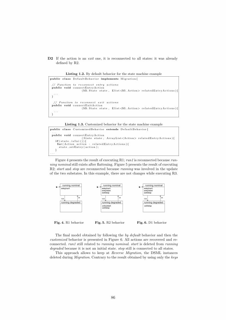
D2 If the action is an exit one, it is reconnected to all states: it was alreadydefined by R2.
Listing 1.2. By default behavior for the state machine example
public c lass DefaultBehavior implements Migrat ion{
// Function to reconnect entry act ionspublic void connectEntryAction
(M3. State s tate , E l i s t<M1. Action> r e la tedEntryAct ions ){. . .
}
// Function to reconnect e x i t ac t ionspublic void connectExitAct ion
(M3. State s tate , E l i s t<M1. Action> r e la tedEntryAct ions ){. . .
}
Listing 1.3. Customized behavior for the state machine example
public c lass CustomizedBehavior extends DefaultBehavior {. . .public void connectEntryAction
( State s tate , ArrayList<Action> r e la tedEntryAct ions ){i f ( s t a t e . i s I n i ( ) ){for ( Action ac t i on : r e la tedEntryAct ions ){s t a t e . setEntry ( ac t i on ) ;
}. . .
Figure 4 presents the result of executing R1; run1 is reconnected because run-ning nominal still exists after flattening. Figure 5 presents the result of executingR2; start and stop are reconnected because running was involved in the updateof the two substates. In this example, there are not changes while executing R3.
running nominal
running degraded
nokok
entry/run1
Fig. 4. R1 behavior
running nominal
running degraded
nokok
entry/run1
entry/start
exit/stop
entry/startexit/stop
Fig. 5. R2 behavior
running nominal
running degraded
nokok
entry/run1
entry/start
exit/stop
exit/stop
Fig. 6. D1 behavior
The final model obtained by following the by default behavior and then thecustomized behavior is presented in Figure 6. All actions are recovered and re-connected. run1 still related to running nominal. start is deleted from runningdegraded because it is not an initial state. stop still is connected to all states.
This approach allows to keep at Reverse Migration, the DSML instancesdeleted during Migration. Contrary to the result obtained by using only the keys
86

mechanism, the dependency graph allows to reconnect all actions without lost.Even if the legacy tool performs creation.
4 Conclusion and Future Works
In this paper, we present an approach to facilitate the legacy tool’s reuse process.In particular, it improves the Reverse Migration for legacy tool’s reuse by meansof a dependency graph. The dependency graph provides a specification of thelegacy tool to be reused. It enables to recover DSML instances deleted beforeusing the legacy tool and to reintegrate them to its original DSML context.
Migration is metamodel dependent only; Reverse Migration is metamodeldependent, tool’s behavior dependent, Migration dependent and original modeldependent.
We are now working on the formalization of Migration and Reverese Migra-tion. The approach will be experimented by reusing some legacy tools in thecontext of video transmission and coding in MPSoC.
References
1. J.-P. Babau and M. Kerboeuf. Domain Specific Language Modeling Facilities. Inproceedings of the 5th MoDELS workshop on Models and Evolution, 2011.
2. J. L. Cybulski. Reuse introduction cybulski abstract introduction to software reuse,1995.
3. K. Garces, F. Jouault, P. Cointe, and J. Bezivin. Managing model adaptation byprecise detection of metamodel changes. In Proceedings of ECMDA-FA, 2009.
4. M. Herrmannsdoerfer, S. Vermolen, and G. Wachsmuth. An extensive catalog ofoperators for the coupled evolution of metamodels and models. In SLE, 2010.
5. M. Kerboeuf and J.-P. Babau. A DSML for reversible transformations. In proceed-ings of the 11th OOPSLA workshop on Domain-Specific Modeling, 2011.
6. D. Mendez, A. Etien, A. Muller, and R. Casallas. Towards Transformation MigrationAfter Metamodel Evolution. In Model and Evolution Wokshop, 2010.
7. S. Sen, N. Moha, B. Baudry, and J.-M. Jezequel. Meta-model Pruning. InACM/IEEE 12th International Conference on Model Driven Engineering Languagesand Systems (MODELS’09), Denver, Colorado, USA, Oct 2009.
8. G. Wachsmuth. Metamodel adaptation and model co-adaptation. In Proceedings ofECOOP, 2007.
87