me 282 – copyright prentice-hall metal and non-metal use in automobiles figure i.1 some of the...
TRANSCRIPT

ME 282 – Copyright Prentice-Hall
Metal and Non-metal Use in Automobiles
Figure I.1 Some of the metallic and nonmetallic materials used in a typical automobile
Principles: 1)Parts and systems do not have to be made of the same material (but material compatibility must be considered when mixing materials).2)Mix improved strength to weight materials as possible to reduce weight (increase mpg), without sacrificing strength, protection, maintainability, and functionality.3)Choose lower cost materials when practical to reduce costs (but be careful because delayed costs and other problems may arise if immediate costs are the only reason behind the decision).

ME 282 – Copyright Prentice-Hall
Permanent Deformation
Figure 1.5 Permanent deformation (also called plastic deformation) of a single crystal subjected to a shear stress: (a) structure before deformation; and (b) permanent deformation by slip. The b/a ratio influences the magnitude of the shear stress required to cause slip.
Principle: Many materials, particularly metals, experience permanent distortion (plasticity) by shear stresses that deform the material through slip plane relative motion. (smaller forces required to shear)

ME 282 – Copyright Prentice-Hall
Defects in a Single-Crystal Lattice
Figure 1.8 Schematic illustration of types of defects in a single-crystal lattice: self-interstitial, vacancy, interstitial, and substitutional
Principles: 1)Materials are not perfect and may have impurity material atoms integrated into the crystalline lattice. 2)It is difficult to make materials pure with few defects. 3)Interstitial atoms, substitutional atoms, and vacancies caused by the impurity materials that relocate atoms can modify the material properties from the pure material.

ME 282 – Copyright Prentice-Hall
Edge Dislocation Movement
Figure 1.10 Movement of an edge dislocation across the crystal lattice under a shear stress. Dislocations help explain why the actual strength of metals is much lower than that predicted by theory.
Principle: The actual strength of materials is much less than that predicted by the pure crystalline structure, because of impurity atoms and vacancies, and anisotropic grain structures and boundaries.

ME 282 – Copyright Prentice-Hall
Solidification of Molten Metal
Figure 1.11 Schematic illustration of the stages during solidification of molten metal; each small square represents a unit cell. (a) Nucleation of crystals at random sites in the molten metal; note that the crystallographic orientation of each site is different. (b) and (c) Growth of crystals as solidification continues. (d) Solidified metal, showing individual grains and grain boundaries; note the different angles at which neighboring grains meet each other.
Principles: 1)It is difficult to get even volumetric cooling of a molten material or heated component, leading to unevenly distributed grains, grain boundaries, or strength properties. The result is distributed and reduced mechanical properties.2)This problem (uneven cooling) is manifested in many manufacturing processes (casting, extrusion, rolling, forging, etc.)

ME 282 – Copyright Prentice-Hall
Recovery, Recrystallization, and Grain Growth Effects
Figure 1.14 Schematic illustration of the effects of recovery, recrystallization, and grain growth on mechanical properties and on the shape and size of grains. Note the formation of small new grains during recrystallization.
Principles: 1)Materials can be heated above a crystallization temperature and then cooled (recrystallized) to generate more uniform material properties.2)Mechanical properties change measurably as the grain structure (and the temperature) changes.

ME 282 – Copyright Prentice-Hall
Physical Properties at
Room Temperature
Principles: 1)Physical properties vary widely among different materials.2)Materials much be chosen carefully to match the environmental demands of the application.3)Physical properties are not sufficient to make a material decision for an application.

Physical Properties in Descending Order
Principle: 1)It is important to understand basic physical property differences between the primary materials used in manufacturing.

ME 282 – Copyright Prentice-Hall
Relative Mechanical Properties of Materials
Principle: 1)It is important to understand basic physical property differences between the primary materials used in manufacturing, but it is equally important to understand mechanical property differences.2)An important related principle is that you must understand both the manufacturing and functioning environment for a material or its product shape, before you build a product and choose its materials.

ME 282 – Copyright Prentice-Hall
Loading and Unloading of Tensile-test Specimen
Figure 2.3 Schematic illustration of the loading and the unloading of a tensile-test specimen. Note that, during unloading, the curve follows a path parallel to the original elastic slope.
Principle: 1)Elastic shape recovery will occur even in plastic deformation for manufacturing processes when load released. (Is the effect less prevalent at higher material temperatures?)

ME 282 – Copyright Prentice-Hall
Power Law Constitutive Model
Kn
where
K = strength coefficient
n = strain hardening exponent
Principles: 1)Stress versus strain is related by an exponential equation as the material is plastically deformed.2)Stress versus strain in the plastic region plots as straight line on a log-log diagram.3)K and n vary significantly among the different metals.4)For many metals the exponent n is a direct measure of the upper end of the strain range for practical manufacturing shape forming processes.5)The area under the stress versus strain curve is a measure of a material’s toughness.

ME 282 – Copyright Prentice-Hall
Temperature Effects on Stress-strain Curves
Figure 2.7 Typical effects of temperature on stress-strain curves. Note that temperature affects the modulus of elasticity, the yield stress, the ultimate tensile strength, and the toughness (area under the curve) of materials.
Principles: 1)Increasing material temperature lowers the forces required to plastically deform the material.2)Many manufacturing processes heat the material to be processed to reduce the operating forces.3)Toughness generally increases as the material temperature increases.

ME 282 – Copyright Prentice-Hall
Effect of Strain Rate on Tensile Strength of Al
Figure 2.8 The effect of strain rate on the ultimate tensile strength for aluminum. Note that, as the temperature increases, the slopes of the curves increase; thus, strength becomes more and more sensitive to strain rate as temperature increases. Source: After J.H. Holloman
Principles: 1.For some materials there is a practical limit to the strain rate, regardless of the elevated temperature for the material being processed. 2.This limits productivity for fast strain rate plastic deformation processes.

Cooling of Metals
Figure 4.4 (a) Cooling curve for the solidification of pure metals. Note that freezing takes place at a constant temperature; during freezing, the latent heat of solidification is given off. (b) Change in density during the cooling of pure metals.
Principles: 1.During metal solidification the temperature in the metal stays constant as the material experiences a phase change from liquid to solid.2.Substantial volume (density) change may occur over a short period of time during the phase change.3.MOST IMPORTANT: Manufacturing shape change processes must account for density changes and thus volume change when using elevated temperatures in the process.
Iron-iron Carbide Phase Diagram
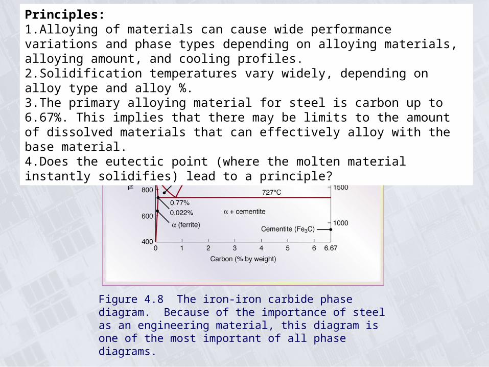
Figure 4.8 The iron-iron carbide phase diagram. Because of the importance of steel as an engineering material, this diagram is one of the most important of all phase diagrams.
Principles: 1.Alloying of materials can cause wide performance variations and phase types depending on alloying materials, alloying amount, and cooling profiles.2.Solidification temperatures vary widely, depending on alloy type and alloy %.3.The primary alloying material for steel is carbon up to 6.67%. This implies that there may be limits to the amount of dissolved materials that can effectively alloy with the base material. 4.Does the eutectic point (where the molten material instantly solidifies) lead to a principle?
Effect of Time and Temperature on Yield Stress
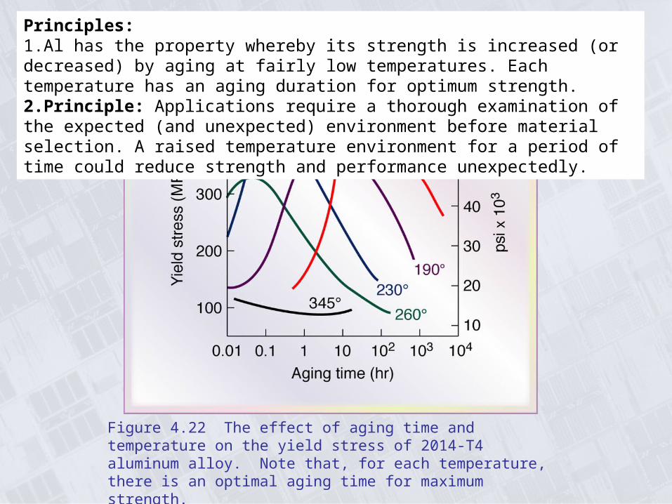
Figure 4.22 The effect of aging time and temperature on the yield stress of 2014-T4 aluminum alloy. Note that, for each temperature, there is an optimal aging time for maximum strength.
Principles: 1.Al has the property whereby its strength is increased (or decreased) by aging at fairly low temperatures. Each temperature has an aging duration for optimum strength.2.Principle: Applications require a thorough examination of the expected (and unexpected) environment before material selection. A raised temperature environment for a period of time could reduce strength and performance unexpectedly.

Outline of Heat Treatment Processes for Surface HardeningPrinciples: 1.Manufactured parts may be designed to vary the properties over the volume of the part depending on the application and interaction with other parts or part components. (e.g., surface hardening)2.The varying properties may be designed or developed into the part, with the applicable manufacturing processes chosen to generate the property variations.

Mechanical Properties of Steel as a Function of Tempering Temperature
Figure 4.25 Mechanical properties of oil-quenched 4340 steel as a function of tempering temperature.
Principle: Heat treatment methods can change the mechanical properties of alloyed materials drastically. (annealing, quenching, tempering…)

Cost of Wrought Metals and Plastics vs. Carbon Steel
Principles: Because a certain material exhibits the best properties for an application does not always make it the best choice, when alternative materials may meet the requirements, and are less costly. Cost can be a factor, but just one of many.
Polymer Chains
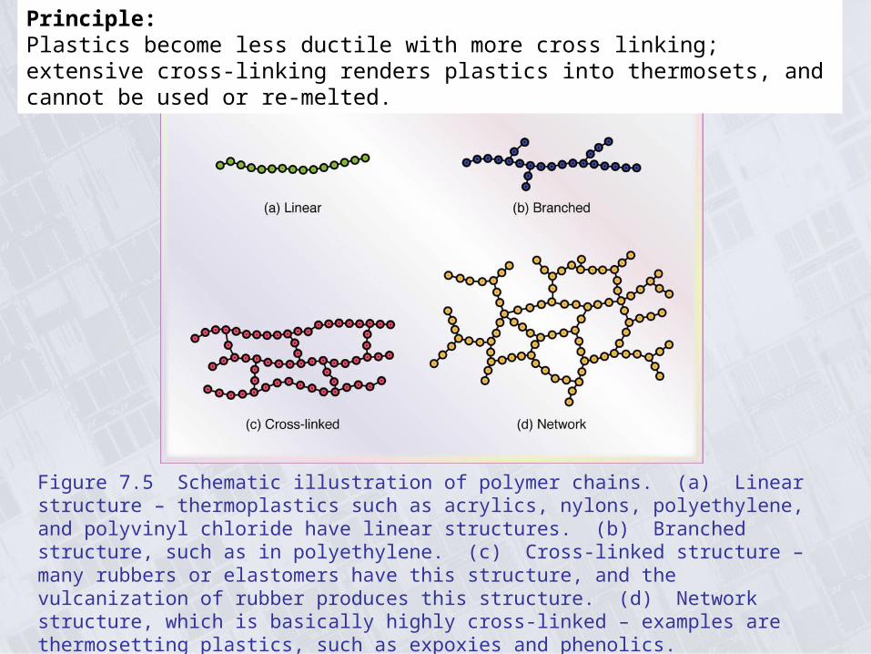
Figure 7.5 Schematic illustration of polymer chains. (a) Linear structure – thermoplastics such as acrylics, nylons, polyethylene, and polyvinyl chloride have linear structures. (b) Branched structure, such as in polyethylene. (c) Cross-linked structure – many rubbers or elastomers have this structure, and the vulcanization of rubber produces this structure. (d) Network structure, which is basically highly cross-linked – examples are thermosetting plastics, such as expoxies and phenolics.
Principle: Plastics become less ductile with more cross linking; extensive cross-linking renders plastics into thermosets, and cannot be used or re-melted.

Ceramic Types and CharacteristicsPrinciple: Hardness and ductility seem to be two properties that are not compatible in a single material. Thus, if you need both in an application then you often combine materials with these differing properties (layer, coat, integrate components, etc.) or locally (spatially) modify properties in a single material (e.g., surface hardening).
Boeing 757-200
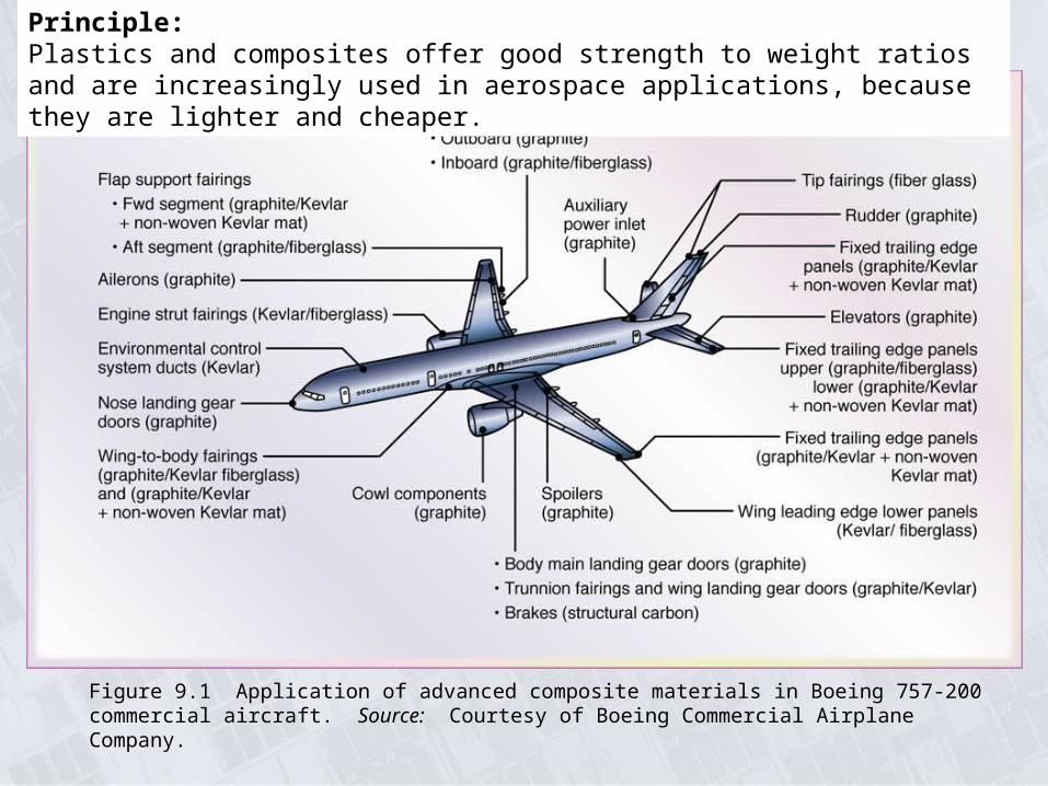
Figure 9.1 Application of advanced composite materials in Boeing 757-200 commercial aircraft. Source: Courtesy of Boeing Commercial Airplane Company.
Principle: Plastics and composites offer good strength to weight ratios and are increasingly used in aerospace applications, because they are lighter and cheaper.

Metal-Matrix Composite Materials and Applications
Principle: Another material combination principle where metals are blended (powder mix, casting, deposition, plating) with other materials which may be another metal or a non-metal. Mixing metal with very strong fibers such as carbon can combine strength with other desirable properties, such as lighter weight (aluminum).

Casting Design and Fluidity Test
Figure 10.8 Schematic illustration of a typical riser-gated casting. Risers serve as reservoirs, supplying molten metal to the casting as it shrinks during solidification.
Figure 10.9 A test method for fluidity using a spiral mold. The fluidity index is the length of the solidified metal in the spiral passage. The greater the length of the solidified metal, the greater is its fluidity.
Principle: Materials can be cast into preferred shapes by melting the material and then pouring the molten material into a preformed shape. More complex shapes that require a 3-D cavity have a number of challenges that make the process difficult:1.Casting shape design must consider cooling shrinkage and internal stresses caused by shape interaction with the retaining material.2.Consider designs, such as risers and air tubes, to ensure proper material flow and the filling of cavities.3.Consider more symmetrical part designs to balance the cooling.4.Casting is not a near shape process and often requires secondary processes to remove flash, risers, etc., or to machine to desired tolerances.

Alloy Solidification
Figure 10.4 Schematic illustration of alloy solidification and temperature distribution in the solidifying metal. Note the formation of dendrites in the mushy zone.
Principles: 1.Different materials have different melting temperatures.2.Material alloying cooling is complicated by the different solidification temperatures, causing nucleation (distributed solidification) over a range of temperatures, often leading to different phases and composition gradients.3.Solidification begins at the cooler exterior boundaries (cooling walls) and slowly progresses inward. Both expendable (lost-foam) and investment (lost-wax) methods provide a more uniform cooling wall thickness.

Solidification Contraction or ExpansionPrinciple: Any process or application that involves substantial temperature change in materials, particularly metals, must account for contraction or expansion, which can be substantial.

Expendable-Pattern Casting Process
Figure 11.11 Schematic illustration of the expendable-pattern casting process, also known as lost-foam or evaporative casting.
Principle: Lost-foam and lost-wax processes provide improved throughput casting and improved grain structures because the cooling boundaries have nearly the same thickness at the outside boundaries of the casting shape. Any process design that can promote more even cooling throughout the shape will generate more uniform internal structures and prevent internal defects (e.g., porosity).

Investment Casting Process
Figure 11.13 Schematic illustration of investment casting (lost-wax) process. Castings by this method can be made with very fine detail and from a variety of metals. Source: Courtesy of Steel Founder’s Society of America.
Additional Principle: 1.Avoid polluting the environment by recovering, as possible, the materials used in the manufacturing process.
Observation: Lost-foam is a more serious pollution process than lost wax.
Effects of Hot Rolling
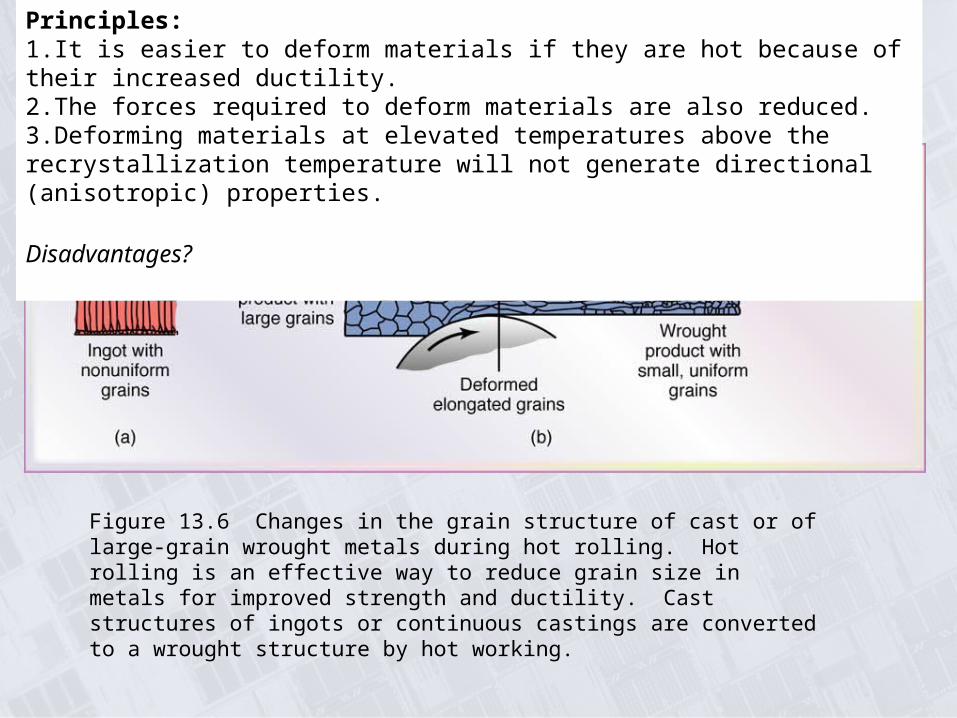
Figure 13.6 Changes in the grain structure of cast or of large-grain wrought metals during hot rolling. Hot rolling is an effective way to reduce grain size in metals for improved strength and ductility. Cast structures of ingots or continuous castings are converted to a wrought structure by hot working.
Principles: 1.It is easier to deform materials if they are hot because of their increased ductility.2.The forces required to deform materials are also reduced.3.Deforming materials at elevated temperatures above the recrystallization temperature will not generate directional (anisotropic) properties.
Disadvantages?

Shape Rolling of an H-section part
Figure 13.12 Steps in the shape rolling of an H-section part. Various other structural sections, such as channels and I-beams, also are rolled by this kind of process.
Principle: Large shaped structural elements are generally rolled. Rollers can use a variety of shape profiles to accomplish the shape transformation.

Forged Components
Figure 14.1 (a) Schematic illustration of the steps involved in forging a knife. (b) Landing-gear components for the C5A and C5B transport aircraft, made by forging. (c) General view of a 445 MN (50,000 ton) hydraulic press. Source: (a) Courtesy of the Mundial LLC. (b and c) Courtesy of Wyman-Gordon Company.
Principle: In combination with a shaped die, high impact punch pressures can shape/forge a component into a desired shape. Generally, the component is at elevated temperatures. The final component will have embedded compressive stresses that make it resistant to fatigue and to crack propagation.

Microstructure as a Function of Manufacturing Method
Figure 14.2 Schematic illustration of a part made by three different processes showing grain flow. (a) Casting by the processes described in Chapter 11. (b) Machining from a blank, described in Part IV of this book, and (c) forging. Each process has its own advantages and limitations regarding external and internal characteristics, material properties, dimensional accuracy, surface finish, and the economics of production. Source: Courtesy of Forging Industry Association.
Principle: Shaping processes can affect the material properties (internal and surface micro-structure/grain properties) of a shaped component by process type, and the properties can vary significantly.
Extrusions and Products Made from Extrusions
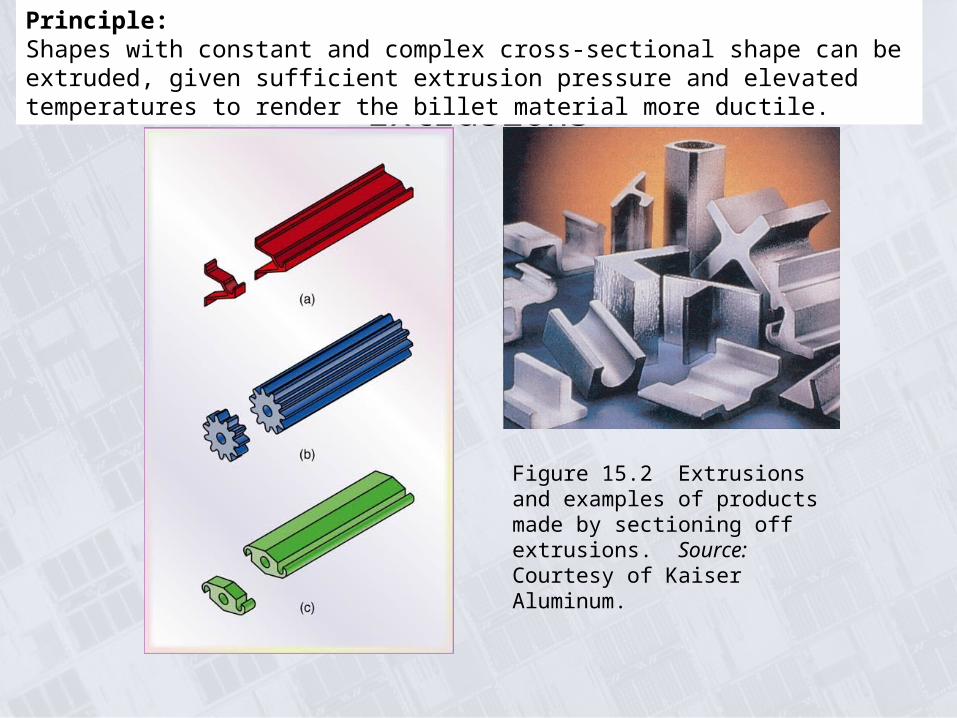
Figure 15.2 Extrusions and examples of products made by sectioning off extrusions. Source: Courtesy of Kaiser Aluminum.
Principle: Shapes with constant and complex cross-sectional shape can be extruded, given sufficient extrusion pressure and elevated temperatures to render the billet material more ductile.

Extrusion Temperature Ranges

Process Variables in Wire Drawing
Figure 15.18 Process variables in wire drawing. The die angle, the reduction in cross-sectional area per pass, the speed of drawing, the temperature, and the lubrication all affect the drawing force, F.
Principle: Many manufacturing processes use shape drawing through smaller diameter dies to reduce the cross-sectional shape and lengthen the product, e.g., wire drawing.

Characteristics of Sheet-Metal Forming ProcessesPrinciple: Shape processes can often be of the same intent but varied in their methods of working the materials, leading to wide variance in material properties and shapes. Sheet metal forming has many different processes to shape products.

Deformation and Tearing in Sheet Metal During Forming
Figure 16.15 The deformation of the grid pattern and the tearing of sheet metal during forming. The major and minor axes of the circles are used to determine the coordinates on the forming-limit diagram in Fig. 16.14b. Source: After S. P. Keeler.
Principle: Sheet metal forming is particularly challenging because modern shape design uses large curvature variations in all directions. The tendency of sheet metal to have some anisotropy makes die forming more difficult.
Springback in Bending
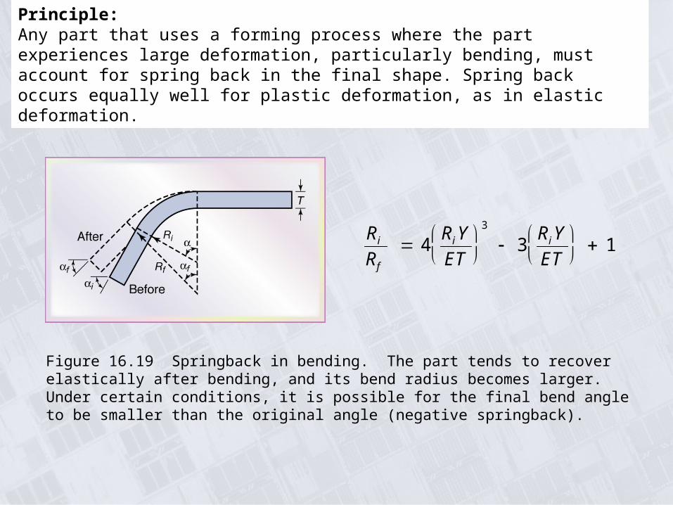
Figure 16.19 Springback in bending. The part tends to recover elastically after bending, and its bend radius becomes larger. Under certain conditions, it is possible for the final bend angle to be smaller than the original angle (negative springback).
Ri
Rf
4RiYET
3
3RiYET
1
Principle: Any part that uses a forming process where the part experiences large deformation, particularly bending, must account for spring back in the final shape. Spring back occurs equally well for plastic deformation, as in elastic deformation.

Parts Made by Powder-Metallurgy
Figure 17.1 (a) Examples of typical parts made by powder-metallurgy processes. (b) Upper trip lever for a commercial sprinkler made by P/M. This part is made of an unleaded brass alloy; it replaces a die-cast part with a 60% savings. (c) Main-bearing metal-powder caps for 3.8 and 3.1 liter General Motors automotive engines. Source: (a) and (b) Reproduced with permission from Success Stories on P/M Parts, 1998. Metal Powder Industries Federation, Princeton, New Jersey, 1998. (c) Courtesy of Zenith Sintered Products, Inc., Milwaukee, Wisconsin.
(a)
(b)
(c)
Principle: Another material combination principle where metals are blended (powder mix) with other materials which may be another metal or a non-metal, to combine strength or other desirable properties. This method produces near shape complex parts, but with reduced strengths and related properties (see next slide), smaller physical volumes, but with higher throughput.

Density as a Function of Pressure and the Effects of Density on Other Properties
Figure 17.10 (a) Density of copper- and iron-powder compacts as a function of compacting pressure. Density greatly influences the mechanical and physical properties of P/M parts. (b) Effect of density on tensile strength, elongation, and electrical conductivity of copper powder. Source: (a) After F. V. Lenel, (b) IACS: International Annealed Copper Standard (for electrical conductivity).

Sintering Time and Temperature for Metals
Principle: Process time is an important parameter when it comes to process economics. If the process takes longer time, then the components must be collected in batches/sets to make their production economical. Smaller part sizes makes this feasible, but more difficult as part size increases.
Sintering temperature for powder metals is in the minutes or hours.

Extruder Schematic
Figure 19.2 (a) Schematic illustration of a typical screw extruder. (b) Geometry of an extruder screw. Complex shapes can be extruded with relatively simple and inexpensive dies.
Principle: Plastics can be easily shaped using melting and extrusion into dies, which are not expensive. The extrusion machines are expensive but justifiable because extrusion usually involves a large number of produced parts. Temperatures are much lower than used to shape metals.

Production of Plastic Film and Bags
Figure 19.5 (a) Schematic illustration of the production of thin film and plastic bags from tube – first produced by an extruder and then blown by air. (b) A blown-film operation. This process is well developed, producing inexpensive and very large quantities of plastic film and shopping bags. Source: Courtesy of Windmoeller & Hoelscher.
(b)
Principle: Mandrels are used in many processes to generate products with internal holes or cavities. Note that this process uses mandrel, die, and air pressure extrusion/drawing to produce thin film and plastic bags. Also note that many processes draw upon previous successful techniques to synthesize new methods for processing new materials.

Parts Made by Rapid-Prototyping
(a)
(b)
(c)
Figure 20.1 Examples of parts made by rapid-prototyping processes: (a) selection of parts from fused-deposition modeling; (b) stereolithography model of cellular phone; and (c) selection of parts form three-dimensional printing. Source: Courtesy of Stratasys, Inc., (b) and (c) Courtesy of 3D Systems, Inc.
Principle: Rapid prototyping methods are processes to generate product or component representations that can be physically touched and viewed. Rapid prototypes represent another use of our senses, without requiring real prototypes, and perhaps better than limited virtual representation. Because they can be created cross-sectional layer by layer they can incorporate cavities within the shape volume.
Principle: New products/components usually demand a physical prototype before making the product.

Common Machining Operations
Figure 21.1 Some examples of common machining operations.
Principle: Machining is a common metal shape forming process wherein raw material is removed by a cutter. For ductile metals the removal process is one of shearing the raw material by an edged cutter. The cutting tool profiles are as varied as the shape they produce. To reduce the cutting forces, the material is removed layer by layer, which means that machining processes take longer time and are expensive.

Two-Dimensional Cutting Process
Figure 21.3 Schematic illustration of a two-dimensional cutting process, also called orthogonal cutting: (a) Orthogonal cutting with a well-defined shear plane, also known as the Merchant Model. Note that the tool shape, depth of cut, to, and the cutting speed, V, are all independent variables, (b) Orthogonal cutting without a well-defined shear plane.
Principle: The simplified 2-D model of metal cutting is used to estimate cutting forces (and hp). Simplified models can provide reasonable estimates for the key design parameters, and then safety factors used to cover the design uncertainties when it comes to loads and power.

Tool-life Curves
Figure 21.17 Tool-life curves for a variety of cutting-tool materials. The negative inverse of the slope of these curves is the exponent n in the Taylor tool-life equation and C is the cutting speed at T = 1 min, ranging from about 200 to 10,000 ft./min in this figure.
Principle: Many of the equations used to estimate performance in manufacturing processes are exponential in form, which will plot as a straight line on log-log diagrams. Cutting tools will lose their cutting effectiveness quicker (exponentially deteriorate) as the cutting speeds increase. Although harder materials last longer at higher cutting speeds they are more fracture sensitive to tensile stresses caused by dynamic load variations.

Feed Marks on a Turned Surface
Figure 21.23 Schematic illustration of feed marks on a surface being turned (exaggerated).
Ra f 2
8Rwhere
f feed
R tool - nose radius
Surface roughness:
Principle: Surface roughness in turning is directly proportional to the square of the feed and inversely proportional to the cutting tool radius. Note that increasing feed will give you a worse surface finish. It is not always easy to increase throughput without sacrificing quality.

Hardness of Cutting Tool Materials as a
Function of Temperature
Figure 22.1 The hardness of various cutting-tool materials as a function of temperature (hot hardness). The wide range in each group of materials is due to the variety of tool compositions and treatments available for that group.
Principle: Materials which retain high temperature hardness are good for machining at higher temperatures and thus at higher speeds. High speed steels lose their hardness at higher speeds and thus are limited to lower cutting speeds. The challenge is that higher speeds leads to a more dynamic loading environment which can degrade of break harder cutting tool materials.

Inserts and Toolholders
Figure 22.2 Typical carbide inserts with various shapes and chip-breaker features: Round inserts are also available, as can be seen in Figs. 22.3c and 22.4. The holes in the inserts are standardized for interchangeability in toolholders. Source: Courtesy of Kyocera Engineered Ceramics, Inc.
Figure 22.3 Methods of mounting inserts on toolholders: (a) clamping and (b) wing lockpins. (c) Examples of inserts mounted with threadless lockpins, which are secured with side screws. Source: Courtesy of Valenite.
Principle: Class videos showed that insert tool manufacturing is complex and expensive, involving powder metallurgy, layer deposition, localized heat treatment, and surface finishing. Modern manufacturing is highly complex, as matched to the complexity of our modern products. Costs do not always equate to appearance or size of parts and generally many process steps are required.
Range of Surface Roughnesses in
Machining Processes
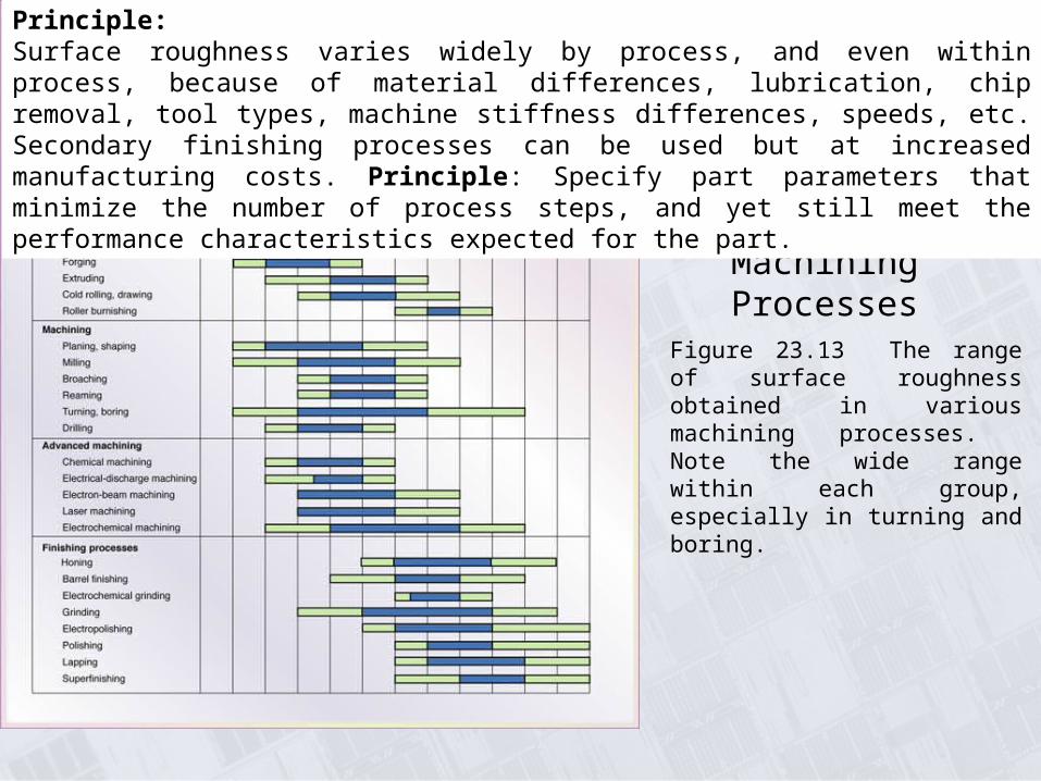
Figure 23.13 The range of surface roughness obtained in various machining processes. Note the wide range within each group, especially in turning and boring.
Principle: Surface roughness varies widely by process, and even within process, because of material differences, lubrication, chip removal, tool types, machine stiffness differences, speeds, etc. Secondary finishing processes can be used but at increased manufacturing costs. Principle: Specify part parameters that minimize the number of process steps, and yet still meet the performance characteristics expected for the part.

Range of Dimensional Tolerances in
Machining as a Function of
Workpiece Size
Figure 23.14 Range of dimensional tolerances obtained in various machining processes as a function of workpiece size. Note that there is an order of magnitude difference between small and large workpieces.
Principle: Dimensional tolerances degrade with part size for all machining and finishing processes. Note from the curve (straight line on log-log diagram) that the tolerance degradation is again exponential (nonlinear). Thus, it is difficult to hold tolerances on large machined parts.

Milling Cutters and Milling Operations
Figure 24.2 Some basic types of milling cutters and milling operations. (a) Peripheral milling. (b) Face milling. (c) End milling. (d) Ball-end mill with indexable coated-carbide inserts machining a cavity in a die block. (e) Milling a sculptured surface with an end mill, using a five-axis numerical control machine. Source: (d) Courtesy of Iscar. (e) Courtesy of The Ingersoll Milling Machine Co.
Principle: Cutter types are as varied as the machining profile or contour required to machine the part features. Likewise the more complex the part features the more complex the machine, leading to 5-axis machines.

Summary of Peripheral Milling Parameters and Formulas
Principle: MRR is an important parameter because it measure the volume removal rate which is an indicator of machining productivity. Mills demand more attention to removal rates because the tool may have a discrete number of cutting edges which limits the feedrate, depending on the spindle rpm (feed per tooth).
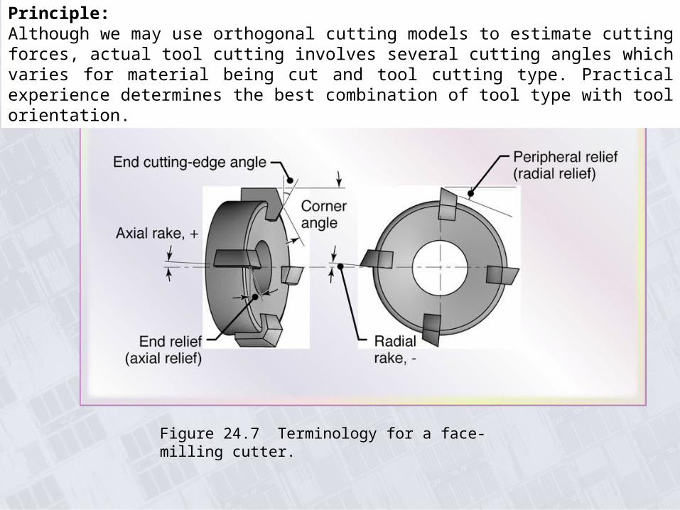
Face-Milling Cutter
Figure 24.7 Terminology for a face-milling cutter.
Principle: Although we may use orthogonal cutting models to estimate cutting forces, actual tool cutting involves several cutting angles which varies for material being cut and tool cutting type. Practical experience determines the best combination of tool type with tool orientation.

Horizontal-Spindle Machining Center
Figure 25.2 A horizontal-spindle machining center equipped with an automatic tool changer. Tool magazines can store up to 200 cutting tools of various functions and sizes. Source: Courtesy of Cincinnati Milacron, Inc.
Principle: Machining is a low productivity forming/shaping process, often requiring some part movement between different machines, or refixturing, etc. This has given rise to more flexible machines which often combine previous single machine functionality into multi-purpose machines called machining centers. These flexible machines may combine the functions of milling with turning, have flexible tool changers or multiple turrets, part handling equipment, and more advanced controls, and interfaces.

Machining Centers
Figure 25.4 (a) Schematic illustration of the top view of a horizontal-spindle machining center showing the pallet pool, set-up station for a pallet, pallet carrier, and an active pallet in operation (shown directly below the spindle of the machine). (b) Schematic illustration of two machining centers with a common pallet pool. Various other pallet arrangements are possible in such systems. Source: Courtesy of Hitachi Seiki Co., Ltd.

Chatter Marks on Surface of Turned Part
Figure 25.13 Chatter marks (right of center of photograph) on surface of a turned part. Source: Courtesy of General Electric Company.
Principle: Vibration is always a problem when you have cyclic energy sources and a dynamic response environment like a tool cutting a rotating part. Chatter represents tool vibration instability while cutting a part and leads to surface imperfections. How do you avoid chatter?

Bonded Abrasives Used in Abrasive-Machining Processes
Figure 25.1 A variety of bonded abrasives used in abrasive-machining processes. Source: Courtesy of Norton Company.
Principle: Another material combination technology where very hard particles (silica, alumina, diamond, titanium carbide, etc.) are combined in a base matrix to provide a grinding surface or tool used to shape parts. The tool can be formed into a variety of grinding edges or profiles as matched to the desired features on the part to be ground. The principle is that harder materials can be used to shape softer materials.

Chemical Milling
Figure 27.2 (a) Missile skin-panel section contoured by chemical milling to improve the stiffness-to-weight ratio of the part. (b) Weight reduction of space-launch vehicles by the chemical milling of aluminum-alloy plates. These panels are chemically milled after the plates first have been formed into shape by a process such as roll forming or stretch forming. The design of the chemically machined rib patterns can be modified readily at minimal cost.
Principle: Chemical milling/machining of aerospace structures is just one application of material removal using chemicals. The general process used is that areas not to be removed are covered by non-reactive materials (masks) and the exposed areas are then removed according to chemical concentration and exposure time. The exposure time and reaction rate can be used to generate good finished tolerances. The principle is that materials will react with certain chemicals and the reaction can be used to remove material over time of exposure.

Stepped Cavities Produced by EDM Process
Figure 27.11 Stepped cavities produced with a square electrode by the EDM process. The workpiece moves in the two principle horizontal directions (x – y), and its motion is synchronized with the downward movement of the electrode to produce these cavities. Also shown is a round electrode capable of producing round or elliptical cavities. Source: Courtesy of AGIE USA Ltd.
Principle:Electrical discharge can be used to remove materials from a workpiece, when the workpiece and tool form two electrodes (+,-). Wire EDM and plunge EDM are two processes that use this principle (plunge shown in the figure). The plunge shape can be varied by shaping the tool appropriately.

Nonmetallic Parts Made by Water-Jet Cutting
Enlargement of Fig. 27.16c. Examples of various nonmetallic parts produced by the water-jet cutting process. Source: Courtesy of Possis Corporation
Principle: Parts can be shaped by removing material using high velocity air or water with hard abrasive materials mixed within the high velocity stream. In effect this is a stream directed grinding process that generate reasonable tolerances, but not as good as other material removal processes.

Fabrication of Integrated Circuits
Figure 28.2 Outline of the general fabrication sequence for integrated circuits.
Principle: One of the most important chemical removal processes is the fabrication sequence used to produce integrated circuits, in combination with the doping of silicon layers using dopants such as arsenic and boron to generate electrical conductivity used in the transistor gating. Note that material properties of materials can be desirably changed with small addition of impurity materials.

Circuit Board Structures and Features
Figure 28.29 Printed circuit board structures and design features.
Principle: Most circuit boards today use surface mounted components and are multi-layered when the board is complex and compact. Multi-layering is needed to provide all the conducting highways between the numerous electrical components. Via holes connect the highways and components between the various layers.

Example: Surface Micromachining of a Hinge
Figure 29.6 (a) SEM image of a deployed micromirror. (b) Detail of the micromirror hinge. Source: Courtesy of Sandia National Laboratories.
(a)(b)
Principle: The chemical removal processes used to produce integrated circuits can be extended to produce micro-electro-mechanical (MEMS) components (hinges, mirrors, gears, actuators, etc.). Additional layering materials are used to constitute the mechanical behavior needed to form the small mechanical components.

Fusion Welding Processes
Principle: Two materials in close proximity can be joined by melting them and then allowing them to coalesce, sometimes mixing in a filler material that is also melted. The energy source for melting is often a large voltage discharge (V= I2R) over two oppositely charged electrodes, one being the part itself, but also note the electron beam energy in the table.

Weld Bead Comparison
Figure 30.14 Comparison of the size of weld beads: (a) laser-beam or electron-beam welding, and (b) tungsten-arc welding. Source: American Welding Society, Welding Handbook (8th ed.), 1991.
(a) (b)
Principle: The weld bead depends on the welding process, with electron beam welding able to reduce the bead size, whereas electrical discharge welding increases bead size.
Figure 30.5 The effect of polarity and current type on weld beads: (a) dc current straight polarity; (b) dc current reverse polarity; (c) ac current.

Ultrasonic Welding
Figure 31.2 (a) Components of an ultrasonic welding machine for making lap welds. The lateral vibrations of the tool tip cause plastic deformation and bonding at the interface of the workpieces. (b) Ultrasonic seam welding using a roller as the sonotrode.
Principle: Workpieces can be joined by adding energy due to vibration or rubbing. Increased energy can either melt the material for local coalescing or increase temperature such that local pressure can cause joining. Ultrasonic vibration excites relative motion and localized temperature increase and may be used in conjunction with pressure to join materials, particularly plastics.

Friction Stir Welding
Figure 31.5 The principle of the friction stir welding process. Alluminum-alloy plates up to 75 mm (3 in.) thick have been welded by this process.
Principle: FSW stir joining elevates the temperature of the material to be joined but below melting temperatures, and uses a hardened rotating tool to stir and blend the materials together. The joined material and mechanical properties are near native values, whereas in arc welding the joined materials only retain about 65% of their native strengths.