me 331 thermo ii lecture 5 - thammasat universitychainarong.me.engr.tu.ac.th/documents/me331...
TRANSCRIPT
7. Refrigeration cycles
Refrigerators and heat pumps; Reversed Carnot cycle; Ideal vapor –
compression refrigeration cycle; Actual vapor compression refrigeration cycle
22 – 24
6. Vapor and combined power cycles
Carnot vapor cycle; Rankine cycle; Deviation of actual vapor power cycles;
Cogeneration; Combined gas – vapor power cycles
19 – 21
5. Gas power cycles
Basic considerations in the analysis of power cycle; Carnot cycle; Air standard
cycle; Reciprocating engines; Otto cycle; Diesel cycle; Stirling cycle; Brayton
cycle; Second – law analysis of gas power cycles
*15 – 18
TopicsSession
Teaching schedule

Objectives
• Evaluate the performance of gas power cycles for which the working fluid
remains a gas throughout the entire cycle.
• Develop simplifying assumptions applicable to gas power cycles.
• Analyze both closed and open gas power cycles.
• Solve problems based on the Otto, Diesel, Stirling, and Ericsson cycles.
• Solve problems based on the Brayton cycle; the Brayton cycle with
regeneration; and the Brayton cycle with intercooling, reheating, and
regeneration.
• Perform second-law analysis of gas power cycles.

Gas power cycle
• Carnot cycle• Otto cycle: ideal cycle for spark-ignition engines• Diesel cycle: ideal cycle for compression-ignition engines• Stirling and Ericsson cycles• Brayton cycle: ideal cycle for gas turbine engine
Analysis of power cycles
• Neglect friction• Neglect the required time for establishing the equilibrium state
If the Carnot cycle is the best possible cycle, why do we not use it as the model cycle for all the heat engine?

The Carnot cycle gives the most efficient heat engine that can operate between two fixed temperatures TH and TL; it is independent of the type of working fluid and can be closed or steady flow.
Carnot CycleProcess Description 1-2 Isothermal heat addition 2-3 Isentropic expansion 3-4 Isothermal heat rejection 4-1 Isentropic compression
Carnot Cycle
Area, which is enclosed by cyclic curve presents net work or heat transfer during the cycle.
η th CarnotL
H
TT, = −1( )2 1in Hq T s s= −
netth
in
wq
η =
in outth
in
q qq−η =
( )3 4out Lq T s s= −

Reciprocating engine
• TDC = Top Dead Center• BDC = Bottom Dead Center• Clearance volume = minimum volume formed in cylinder
Compression ratio, r = Max. volumeMin. volume
BDC
TDC
VV
=

Reciprocating engine
netW MEP Piston area Stroke= × ×
Work F s= ⋅
• MEP = Mean Effective Pressure
netW MEP Displacement volume= ×
minmax
MEP netWV V
=−
Larger value of MEP gives more net work per cycle, thus perform better

Analysis of power cycles• The working fluid remains a gas throughout the entire cycle. • Neglect friction• Neglect the required time for establishing the equilibrium state
• The working fluid is air, which continuously circulates in a closed loop and always behaves as an ideal gas.
• All the processes that make up the cycle are internally reversible.• The combustion process is replaced by a heat-addition process
from an external source.• The exhaust process is replaced by a heat-rejection process that
restores the working fluid to its initial state.
Air-standard assumptions
Gas power cycles

Otto cycle• An ideal cycle for spark-ignition engines• Nikolaus A. Otto (1876) built a 4-stoke engine
Ideal Otto cycle
Actual 4-stoke ignition engine


Spark plug

The air-standard Otto cycle is the ideal cycle that approximates the spark-ignition combustion engine.
Process Description 1-2 Isentropic compression 2-3 Constant volume heat addition 3-4 Isentropic expansion 4-1 Constant volume heat rejection
The T-s and P-v diagrams are
The air-standard Otto cycle

Thermal Efficiency of the Otto cycle:
netth
in
WQ
η =
Apply 1st law closed system to process 2-3, constant volume heat addition
Thus, for constant specific heats,
, 23 23netQ U= Δ
, 23 3 2( )net in vQ Q mC T T= = −
net
in
= 1in out out
in in
Q Q QQ Q−
= = −
,23 ,23 23net netQ W U− = Δ
,23 ,23 ,23net other bW W W= +3
2
0 0PdV= + =∫
,23 ,23 23in outE E E− = Δ

Apply 1st law closed system to process 4-1, constant volume heat rejection
Thus, for constant specific heats,
1 4 4 1( ) ( )out v vQ mC T T mC T T= − − = −
The thermal efficiency becomes
η th Ottoout
in
v
v
QQmC T TmC T T
,
( )( )
= −
= −−−
1
1 4 1
3 2
, 41 41netQ U= Δ
, 41 1 4( )net out vQ Q mC T T= − = −
η th OttoT TT T
T T TT T T
,( )( )
( / )( / )
= −−−
= −−−
1
1 11
4 1
3 2
1 4 1
2 3 2
,41 ,41 41in outE E E− = Δ
,41 ,41 41net netQ W U− = Δ4
,41 ,41 ,411
0 0net other bW W W PdV= + = + =∫

Processes 1-2 and 3-4 are isentropic, so
Since V3 = V2 and V4 = V1,
3 32 4
1 4 1 2
T TT TorT T T T
= =
The Otto cycle efficiency becomes
η th OttoTT, = −1 1
2η th Otto
T TT T
T T TT T T
,( )( )
( / )( / )
= −−−
= −−−
1
1 11
4 1
3 2
1 4 1
2 3 2
3 2
4 1
V VT T
=
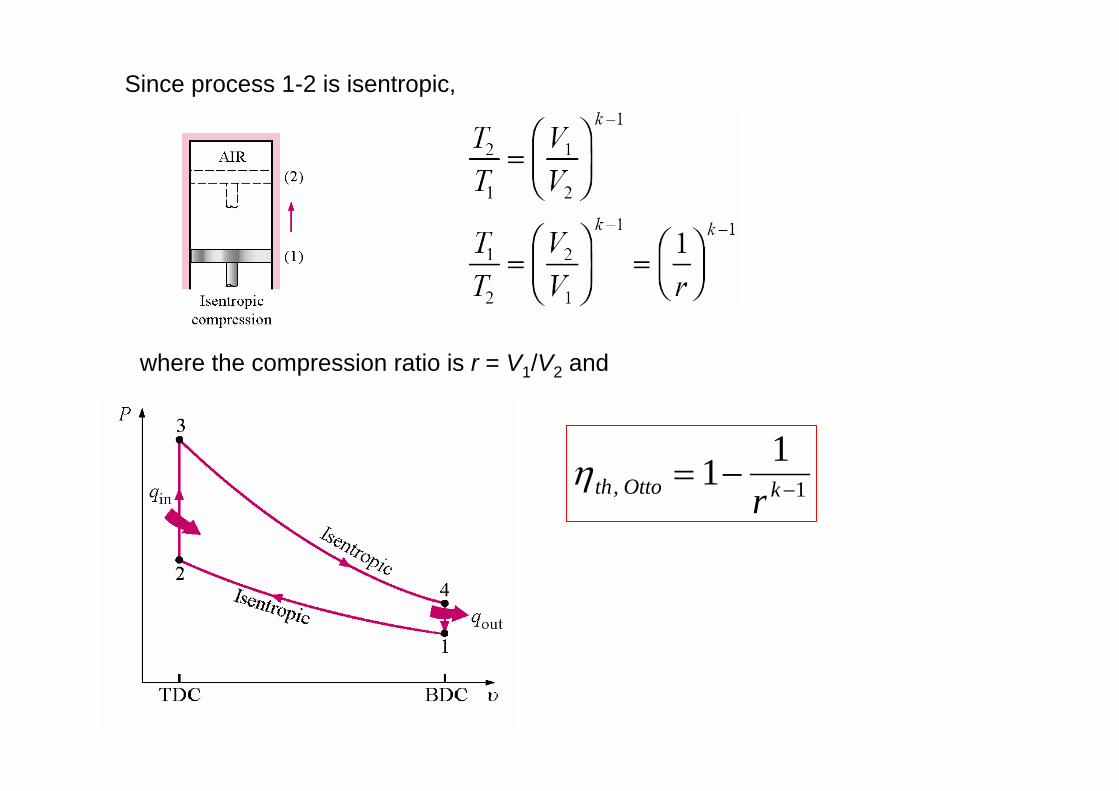
Since process 1-2 is isentropic,
where the compression ratio is r = V1/V2 and
η th Otto kr, = − −1 11

- Increasing the compression ratio increases the thermal efficiency. - But there is a limit on r depending upon the fuel. Fuels under high
temperature resulting from high compression ratios will prematurely ignite, causing knock (auto ignition).
Thermal efficiency of the ideal Otto cycle
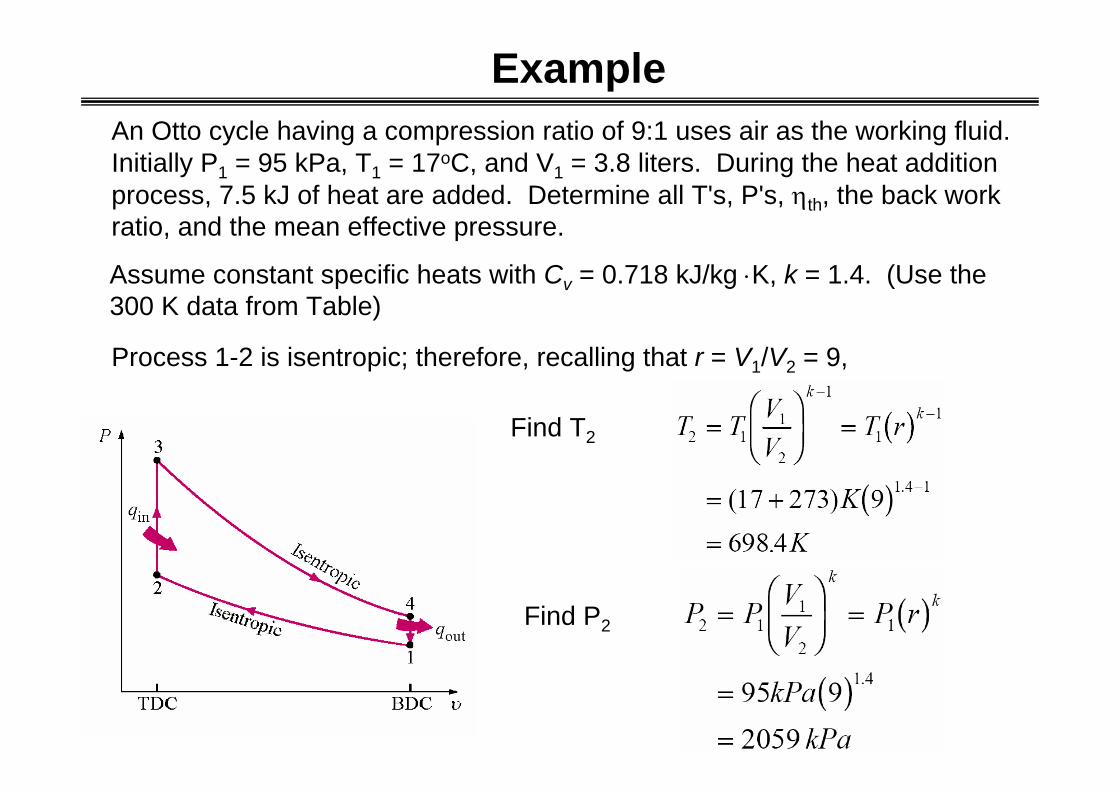
An Otto cycle having a compression ratio of 9:1 uses air as the working fluid. Initially P1 = 95 kPa, T1 = 17oC, and V1 = 3.8 liters. During the heat addition process, 7.5 kJ of heat are added. Determine all T's, P's, ηth, the back work ratio, and the mean effective pressure.
Process 1-2 is isentropic; therefore, recalling that r = V1/V2 = 9,
Example
Assume constant specific heats with Cv = 0.718 kJ/kg ⋅K, k = 1.4. (Use the 300 K data from Table)
Find T2
Find P2

Q mC T Tin v= −( )3 2
Let qin = Qin / m and m = V1/v1
v RTP
kJkg K
K
kPam kPa
kJmkg
11
1
3
3
0 287 290
95
0875
=
= ⋅
=
. ( )
.
q Qm
Q vV
kJ
mkgm
kJkg
inin
in= =
=⋅
=
−
1
13
3 37 50875
38 10
1727
..
.
T T qC
K
kJkgkJ
kg KK
in
v3 2
698 41727
0 718
31037
= +
= +
⋅=
..
.
3 2in
v
qT TC
= +Find T3

Using the combined gas law (V3 = V2)
P P TT
MPa3 23
2
9 15= = .
Process 3-4 is isentropic; therefore,
1 1 1.4 13
4 3 34
1 1(3103.7)9
1288.8
k kVT T T KV r
K
− − −⎛ ⎞ ⎛ ⎞ ⎛ ⎞= = =⎜ ⎟ ⎜ ⎟ ⎜ ⎟⎝ ⎠ ⎝ ⎠⎝ ⎠
=
• Find P3
• Find T4
• Find P4

Process 4-1 is constant volume. So the first law for the closed system gives, on a mass basis,
4 1
4 1
( )
( )
out v
outout v
Q mC T TQq C T Tm
= −
= = −
The first law applied to the cycle gives (Recall Δucycle = 0)
net net in outw q q q= = −
0.718 (1288.8 290)
717.1
kJ Kkg KkJkg
= −⋅
=
(1727 717.4)
1009.6
kJkg
kJkg
= −
=
Find qout
net net in outw q q q= = −In order to find ηth , we must know net work first

The thermal efficiency is
η th Ottonet
in
wq
kJkg
kJkg
or
,
.
. .
= =
=
1009 6
1727
0 585 58 5%
The mean effective pressure is
max min max min
net netW wMEPV V v v
= =− −
1
3
3
(1 1/ )
1009.61298
10.875 (1 )9
netwv r
kJm kPakg kPa
m kJkg
=−
= =−
1 2
netwv v
=−
1 2 1(1 / )netw
v v v=
−

The back work ratio is
2 112 2 1
34 3 4 3 4
( ) ( )( ) ( )
v
v
C T Tu T Tu C T T T T
−Δ −= = =−Δ − −
exp
compwBWR
w=
0.225 22.5%or=

Diesel Cycle

Process Description 1-2 Isentropic compression 2-3 Constant pressure heat addition 3-4 Isentropic expansion 4-1 Constant volume heat rejection
The P-v and T-s diagrams are
Air-Standard Diesel CycleThe air-standard Diesel cycle is the ideal cycle that approximates the
Diesel combustion engine

Thermal efficiency of the Diesel cycle
η th Dieselnet
in
out
in
WQ
QQ, = = −1
Apply the first law closed system to process 2-3, P = constant.
Thus, for constant specific heats
, 23 23 2 3 2( )netQ U P V V= Δ + −
,23 ,23net netQ W U− = Δ
in outE E E− = Δ
3
,23 ,23 ,232
0net other bW W W PdV= + = + ∫( )2 3 2P V V= −
, 23 3 2 3 2( ) ( )net in vQ Q mC T T mR T T= = − + −
3 2( )in pQ mC T T= −
Find Qin

Apply the first law closed system to process 4-1, V = constant
Thus, for constant specific heats
, 41 1 4
1 4 4 1
( )
( ) ( )net out v
out v v
Q Q mC T T
Q mC T T mC T T
= − = −
= − − = −
The thermal efficiency becomes , 1 outth Diesel
in
η = −
in outE E E− = Δ
Find Qout
,41 ,41 41net netQ W U− = Δ1
,41 ,41 ,414
0net other bW W W PdV= + = + ∫
, 41 41netQ U= Δ
4 1
3 2
( )1( )
v
p
mC T TmC T T
−= −
−

4 1,
3 2
( )1( )
vth Diesel
p
C T TC T T
−η = −
−
PVT
PVT
P P
TT
VV
rc
3 3
3
2 2
23 2
3
2
3
2
= =
= =
where
where rc is called the cutoff ratio, defined as V3 /V2, and is a measure of the duration of the heat addition at constant pressure. Since the fuel is injected directly into the cylinder, the cutoff ratio can be related to the number of degrees that the crank rotated during the fuel injection into the cylinder.
1 4 1
2 3 2
( / 1)11( / 1)
T T Tk T T T
−= −
−

η th Diesel
ck
c
kck
c
kT T TT T T
kTT
rr
rr
k r
,( / )( / )
( )
( )
= −−−
= −−−
= −−−−
1 1 11
1 1 11
1 1 11
1 4 1
2 3 2
1
2
1
3 3
2 2c
T V rT V
= =
When rc > 1 for a fixed r, ηth,Diesel < ηth,Otto
But, since rDiesel > rOtto , ηth,Diesel > ηth,Otto .
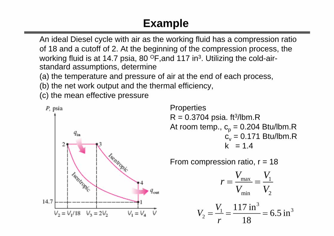
An ideal Diesel cycle with air as the working fluid has a compression ratio of 18 and a cutoff of 2. At the beginning of the compression process, the working fluid is at 14.7 psia, 80 OF,and 117 in3. Utilizing the cold-air-standard assumptions, determine (a) the temperature and pressure of air at the end of each process,(b) the net work output and the thermal efficiency,(c) the mean effective pressure
Example
PropertiesR = 0.3704 psia. ft3/lbm.RAt room temp., cp = 0.204 Btu/lbm.R
cv = 0.171 Btu/lbm.Rk = 1.4
From compression ratio, r = 18
max 1
min 2
V VrV V
= =
331
2117 in 6.5 in
18VVr
= = =

From cutoff ratio, rc= 2
3
2c
VrV
=
( )( )3 33 2 6.5 in 13 inV = =
34 1 117 inV V= =
Process 1-2 (isentropic compression of an ideal gas, constant specific heat)1
12 1
2
kVT TV
−⎛ ⎞
= ⎜ ⎟⎝ ⎠
12 1
2
kVP PV⎛ ⎞
= ⎜ ⎟⎝ ⎠
( )( )1.4 1540 R 18 1716 R−= =
( )( )1.414.7 18 841psia psia= =
T2 and P2

Process 2-3 (constant pressure heat addition to an ideal gas)
T3 and P3
3 2 841P P psia= =
3 32 2
2 3
PVPVT T
= → ( )( )33 2
2
1716 R 2 3432 RVT TV⎛ ⎞
= = =⎜ ⎟⎝ ⎠
Process 3-4 (isentropic expansion of an ideal gas, constant specific heats)
T4 and P4
1
34 3
4
kVT TV
−⎛ ⎞
= ⎜ ⎟⎝ ⎠
34 3
4
kVP PV⎛ ⎞
= ⎜ ⎟⎝ ⎠
( )1.4 1133432 R 1425 R
117
−⎛ ⎞= =⎜ ⎟⎝ ⎠
( )1.413841 38.8
117psia psia⎛ ⎞= =⎜ ⎟
⎝ ⎠

(b) Net work net in outW Q Q= −
( ) ( )3 2 3 2in pQ m h h mc T T= − = −
( )( )( )( )
31 1
331
14.7 psia 117 1 ft 0.00498 lbm1728 in0.3704 psia.ft /lbm.R 540 R
PVmRT
⎛ ⎞= = =⎜ ⎟
⎝ ⎠
( )( )( )0.00498 0.24 3432 1716 2.051 BtuinQ = − =
( ) ( )4 1 4 1out vQ m u u mc T T= − = −
( )( )( )0.00498 0.171 1425 540 0.754 BtuoutQ = − =
2.051 0.754 1.297 BtunetW = − =

(c) Mean effective pressure
max min 1 2
net netW WMEPV V V V
= =− −
( ) 3
1297 Btu 778.17 lbf.ft 12 in= 110 psia117-6.5 in 1 Btu 1 ft
⎛ ⎞⎛ ⎞ =⎜ ⎟⎜ ⎟⎝ ⎠⎝ ⎠
Thermal efficiency
,1.297 0.6322.051
netth Diesel
in
WQ
η = = =

Summary of Diesel cycle
, 1
111( 1)
kc
th Diesel kc
rr k r−
−η = −
−
Thermal efficiency
Cutoff ratio, rc
Defined as V3 /V2, and is a measure of the duration of the heat addition at constant pressure.

Robert Stirling patented his Heat Economiser in 1816
The power piston compresses the enclosed air in the cold end of the displacercylinder. The displacer then shifts the air from cold to hot chambers. The pistonis driven back, the power stroke, by the air expanding in the hot end.
Stirling engine

Stirling engine

Ericsson Engine

Stirling and Ericsson cycles-Involve an isothermal heat addition process at TH and isothermal heat rejection process at TL
- Both cycles utilize regeneration- a process during which heat is transferred to a thermal energy
storage device (called a regenerator) during one part of the cycle and is transferred back to the working back to the working fluid during the other part of the cycle.

1-2 T = constant expansion (heat addition from the external source)
2-3 v = constant regeneration (internal heat transfer from the working fluid to the regenerator
3-4 T = constant compression (heat rejection to the external sink)
4-1 v = constant regeneration (internal heat transfer from the regenerator back to the working fluid)
Ideal stirling cycle

Stirling and Ericsson cycles differ from the Carnot cycle in that two isentropic processes are replaced by two constant volume regeneration processes in Stirlingcycle and by two constant pressure regeneration processes in Ericsson cycle.
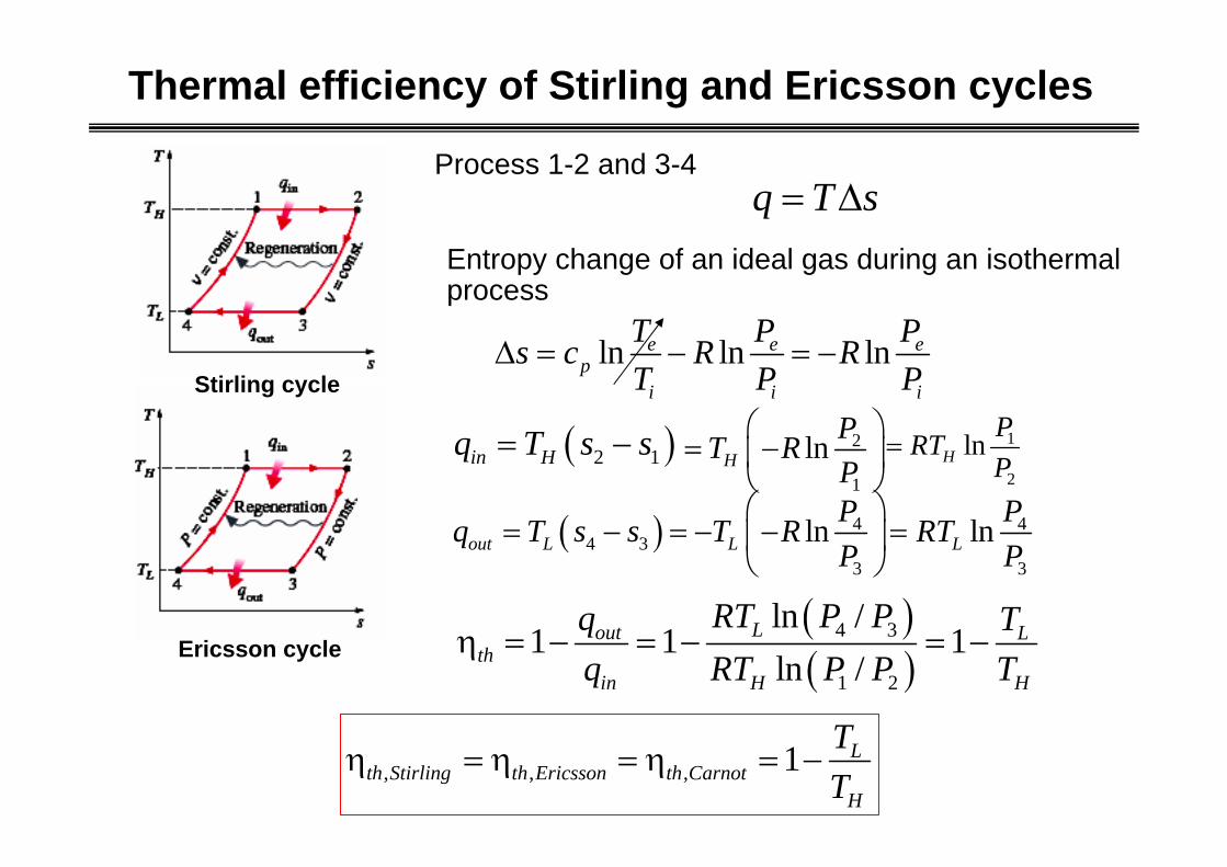
Thermal efficiency of Stirling and Ericsson cycles
, , , 1 Lth Stirling th Ericsson th Carnot
H
TT
η = η = η = −
q T s= ΔProcess 1-2 and 3-4
Stirling cycle
Ericsson cycle
Entropy change of an ideal gas during an isothermal process
ln ln lne e ep
i i i
T P Ps c R RT P P
Δ = − = −
( )2 1in Hq T s s= − 2
1
lnHPT RP
⎛ ⎞= −⎜ ⎟
⎝ ⎠1
2
lnHPRTP
=
( ) 4 44 3
3 3
ln lnout L L LP Pq T s s T R RTP P
⎛ ⎞= − = − − =⎜ ⎟
⎝ ⎠
( )( )
4 3
1 2
ln /1 1 1
ln /Lout L
thin H H
RT P Pq Tq RT P P T
η = − = − = −

Merit and demerit of Stirling and Ericsson engines
Difficult to achieve in practice• They involve heat transfer through a differential temperature
difference in all components including regenerator.• Need large surface for allowing heat transfer or need long time for
the process.Pressure losses in the generator are considerable.
MeritDue to external combustion in both cycles
- A variety of fuel can be used.- There are more time for combustion, resulting in more
complete combustion (less pollution)Because these cycles operate on closed cycles,
- A working fluid (e.g.,H and He) that has most desirable characteristics (stable, chemically inert, high thermal conductivity) can be used.
Demerit

• The Brayton cycle is the air-standard ideal cycle approximation for the gas turbine engine.
Brayton Cycle
A closed cycle gas turbine engine with air standard assumptions
A open cycle gas turbine engine
• The Brayton cycle was first proposed by George Brayton around 1870.
• This cycle differs from the Otto and Diesel cycles - Processes making the cycle occur in open systems or control volumes.

Brayton Cycle
1-2 Isentropic compression (in a compressor)2-3 Constant pressure heat addition 3-4 Isentropic expansion (in a turbine)4-1 Constant pressure heat rejection

Thermal efficiency of the Brayton cycle
η th Braytonnet
in
out
in
WQ
QQ, = = −1
Process 2-3 for P = constant (no work), steady-flow, and neglect changes in kinetic and potential energies.
The conservation of mass gives m mm m m
in out== =2 3
For constant specific heats, the heat added per unit mass flow is
3 2
3 2
( )
( )in
in p
Q m h h
Q mC T T
= −
= −3 2( )in
in pQq C T Tm
= = −
E Em h Q m h
in out
in
=
+ =2 2 3 3

Process 4-1; constant specific heats
( )( )
( )
Q m h hQ mC T T
q Qm
C T T
out
out p
outout
p
= −
= −
= = −
4 1
4 1
4 1
The thermal efficiency becomes
η th Braytonout
in
out
in
p
p
C T TC T T
,
( )( )
= − = −
= −−
−
1 1
1 4 1
3 2
η th BraytonT TT T
T T TT T T
,( )( )
( / )( / )
= −−−
= −−−
1
1 11
4 1
3 2
1 4 1
2 3 2

Processes 1-2 and 3-4 are isentropic
Since P3 = P2 and P4 = P1,
3 32 4
1 4 1 2
orT TT TT T T T
= =
The Brayton cycle efficiency becomes
η th BraytonTT, = −1 1
2
Process 1-2 is isentropic,
where the pressure ratio is rp = P2/P1
ηth Braytonp
k kr, ( )/= − −1 11

ηth Braytonp
k kr, ( )/= − −1 11
Brayton cycle

The ideal air-standard Brayton cycle operates with air entering the compressor at 95 kPa, 22oC. The pressure ratio rp is 6:1 and the air leaves the heat addition process at 1100 K. Determine the compressor work and the turbine work per unit mass flow, the cycle efficiency, the back work ratio, and compare the compressor exit temperature to the turbine exit temperature. Assume constant properties.
E Em h W m h
in out
comp
=
+ =1 1 2 2
The conservation of mass gives
m mm m m
in out== =1 2
Example
For steady-flow and neglect changes in kinetic and potential energies to process 1-2 for the compressor. Note that the compressor is isentropic.

For constant specific heats, the compressor work per unit mass flow is
( )
( )
( )
W m h h
W mC T T
wW
mC T T
comp
comp p
compcomp
p
= −
= −
= = −
2 1
2 1
2 1
Since the compressor is isentropicw C T T
kJkg K
K
kJkg
comp p= −
=⋅
−
=
( )
. ( . )
.
2 1
1005 492 5 295
19815

Process 3-4; constant specific heats
( )( )
( )
W m h hW mC T T
w Wm
C T T
turb
turb p
turbturb
p
= −
= −
= = −
3 4
3 4
3 4
Since process 3-4 is isentropic
Since P3 = P2 and P4 = P1,
( 1) /
4
3
( 1) / (1.4 1) /1.4
4 3
1
1 11100 659.16
k k
p
k k
p
TT r
T T K Kr
−
− −
⎛ ⎞= ⎜ ⎟⎜ ⎟⎝ ⎠
⎛ ⎞ ⎛ ⎞= = =⎜ ⎟ ⎜ ⎟⎜ ⎟ ⎝ ⎠⎝ ⎠

Process 2-3
3 2in
inQq h hm
= = −
The net work done by the cycle is w w wkJkg
kJkg
net turb comp= −
= −
=
( . . )
.
442 5 19815
244 3
2 3
2 2 3 3in
m m m
m h Q m h
= =
+ =
3 2( ) 1.005 (1100 492.5) 609.6pkJ kJC T T K
kg K kg= − = − =
⋅
w C T T kJkg K
K
kJkg
turb p= − =⋅
−
=
( ) . ( . )
.
3 4 1005 1100 659 1
442 5

The cycle efficiency becomes
,net
th Braytonin
wq
η =
The back work ratio is defined as
198.150.448
442.5
kJkgkJkg
= =
compin
out turb
wwBWRw w
= =
Note that T4 = 659.1 K > T2 = 492.5 K, or the turbine outlet temperature is greater than the compressor exit temperature.
244.30.40 40%
609.6
kJkg orkJkg
= =

What happens to ηth, win /wout, and wnet as the pressure ratio rp is increased?
, ( 1) /
11netth Brayton k k
in p
wq r −η = = −
Efficiency of Brayton cycle depends on
• Pressure ratio, P2/P1 or rp
• Specific heat ratio, k
Limitation in an actual gas turbine cycle• Max. temp. is at the outlet of combustor(T3)
- Limitation temp. in materials
Same Tmax and plot wnet in various rp
(combustor)

3 4 2 1( ) ( )p pC T T C T T= − − −
The effect of the pressure ratio on the net work done.
net turb compw w w= −
Net work is zero when/( 1)
3
1
1k k
p pTr and rT
−⎛ ⎞
= = ⎜ ⎟⎝ ⎠
What happens to ηth, win /wout, and wnet as the pressure ratio rp is increased?
3 4 3 1 2 1(1 / ) ( / 1)p pC T T T C T T T= − − −
( 1) /3 1( 1) /
1(1 ) ( 1)k kp p pk k
p
C T C T rr
−−= − − −
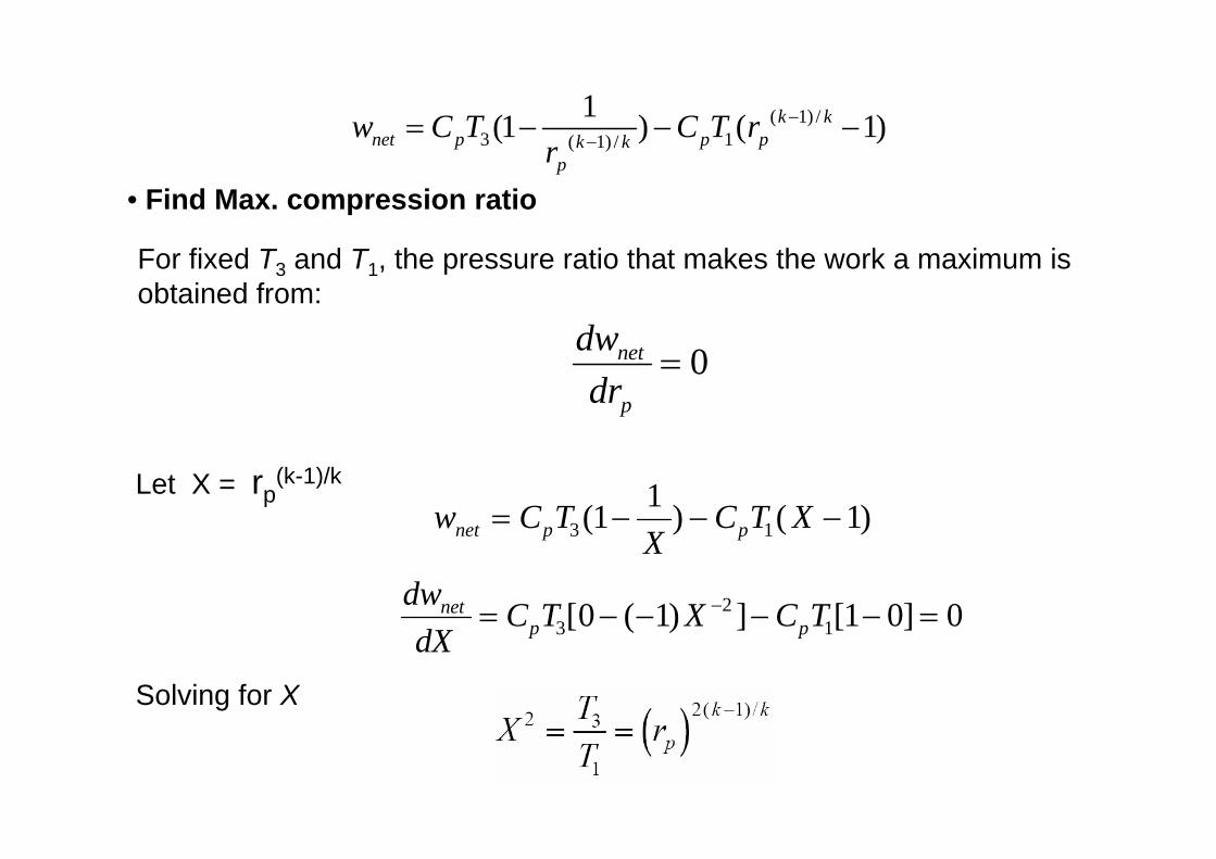
For fixed T3 and T1, the pressure ratio that makes the work a maximum is obtained from:
dwdr
net
p
= 0
w C TX
C T Xnet p p= − − −3 11 1 1( ) ( )
dwdX
C T X C Tnetp p= − − − − =−
32
10 1 1 0 0[ ( ) ] [ ]
Solving for X
Let X = rp(k-1)/k
( 1) /3 1( 1) /
1(1 ) ( 1)k knet p p pk k
p
w C T C T rr
−−= − − −
• Find Max. compression ratio

• When rp = rp, max work, T4 = T2• When rp < rp, max work, T4 > T2• When rp > rp, max work, T4 < T2
For the ideal Brayton cycle
Then, the rp that makes the work a maximum for the constant property case and fixed T3 and T1 is
3 32 4
1 4 1 2
orT TT TT T T T
= =
And show that the following results are true.2”
2’
4’
4”

Example: ideal gas turbine
• The cycles does not involve any friction. Therefore, the working fluid does not experience any pressure drop as it flow in pipe or devices such as heat exchanger.
• All expansion and compression processes take place in a quasi-equilibrium manner.
• The pipe connecting the various components of a system are well insulated, and heat transfer through them is negligible.
Air standard assumptions

From Table A-17
From table and s1 = s2
Information
Pressure ratio,rp = 8
Temperature at the inlet compressor = 300 K
Temperature at the inlet turbine = 1300 K
Ideal Brayton cycle

From Table A-17
(b) Back work ratio
From table and s3 = s4
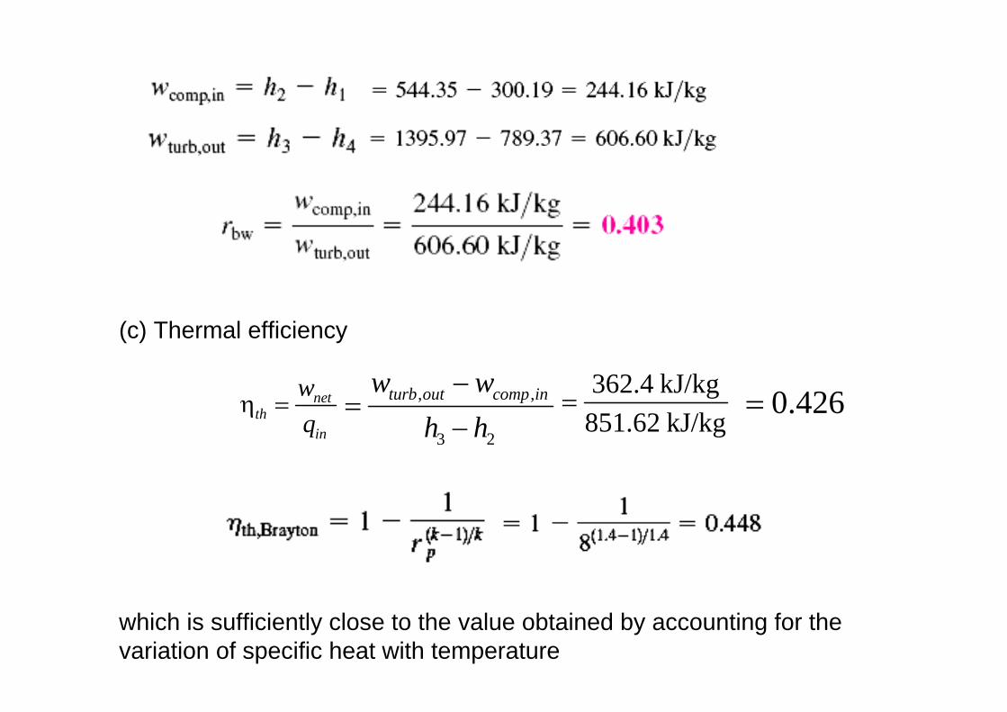
(c) Thermal efficiency
which is sufficiently close to the value obtained by accounting for the variation of specific heat with temperature
netth
in
wq
η = , ,
3 2
turb out comp inw wh h−
=−
362.4 kJ/kg851.62 kJ/kg
= 0.426=

Deviation of actual gas turbine cycles from idealized ones
Pressure drop during the heat-addition and heat rejection
Due to irreversiblility, actual work input to the compressor is more and the actual work output from the turbine is less
2 1
2 1
s sc
a a
w h hw h h
−η = ≅
−
3 4
3 4
a aT
s s
w h hw h h
−η = ≅
−
Compressor
Turbine
Isentropic efficiency
Pressure & Entropy generation in actual processes

Example: actual gas turbine
Assuming a compressor efficiency of 80 percent and a turbine efficiency of 85 percent, determine (a) the back work ratio, (b) the thermal efficiency, and (c) the turbine exit temperature of the gas turbine cycle discussed in the previous example (ideal gas turbine)
From previous example (ideal gas turbine)
, 244.16 kJ/kgs compw =
, 606.6 kJ/kgs turbw =
For actual gas turbine
,,
s compcomp in
c
ww =
η
Compressor
turbine
, ,turb out T s turbw w= η
244.16 kJ/kg 305.2 kJ/kg0.8
= =
( )( )0.85 606.6 kJ/kg 515.61 kJ/kg= =
, 0.403s bwr =0.426thη =

Back work ratio
,
,
comp inbw
turb out
wr
w= 305.2 0.592
515.61= =
back work ratio in actual case is larger than that in ideal case, where rs,bw = 0.403
(b) Thermal efficiency
netth
in
wq
η = , ,
3 2
turb out comp in
a
w wh h
−=
−
, 2 1comp in aw h h= − 2 1 ,a comp inh h w→ = +
300.19 305.2 605.36 /kJ kg= + =
515.61 605.39 0.2661395.97 605.36
−= =
−
Thermal efficiency in actual case is lower than that in ideal case, where ηth = 0.426

(c) Air temperature at the turbine exit
Apply energy balance on turbine
, 3 4 4 3 ,turb out a a turb outw h h h h w= − → = −
4 1395.97 515.61 880.36 /ah kJ kg= − =
Find T4a from Table
T4a = 853 K
The temperature at turbine exit is considerably higher than that at the compressor exit (T2a = 598 K), which suggests the use of regeneration to reduce fuel cost

The Brayton cycle with regeneration
• Temperature of the exhaust gas from turbine is higher than the temperature of the air leaving the compressor.
• Use regenerator or recuperator as an heat exchanger

• Actual heat transfer from exhaust gas to the air
• Max. heat transfer from exhaust gas to the air
, 5 2regen actq h h= −
,max 5 2 4 2regenq h h h h′= − = −
• Extent to which a regenerator approaches an ideal regenerator is called the effectiveness ε,
, 5 2
,max 4 2
regen act
regen
q h hq h h
−ε = =
−
T4 is temp from exhaust turbine gas

• For the cold-air-standard assumptions are utilized, it reduces to
5 2
4 2
T TT T−
ε ≈−
• Higher effectiveness requires the use of larger regenerator
• Due to higher price of components and larger pressure drop, the use of larger regenerator with very high effectiveness does not justify saving money
• Thermal efficiency of an ideal Braytoncycle with regenerator
( )1
1,
3
1kk
th regen pT rT
−⎛ ⎞η = − ⎜ ⎟
⎝ ⎠
• T3 is Tmax, and T1 is Tmin
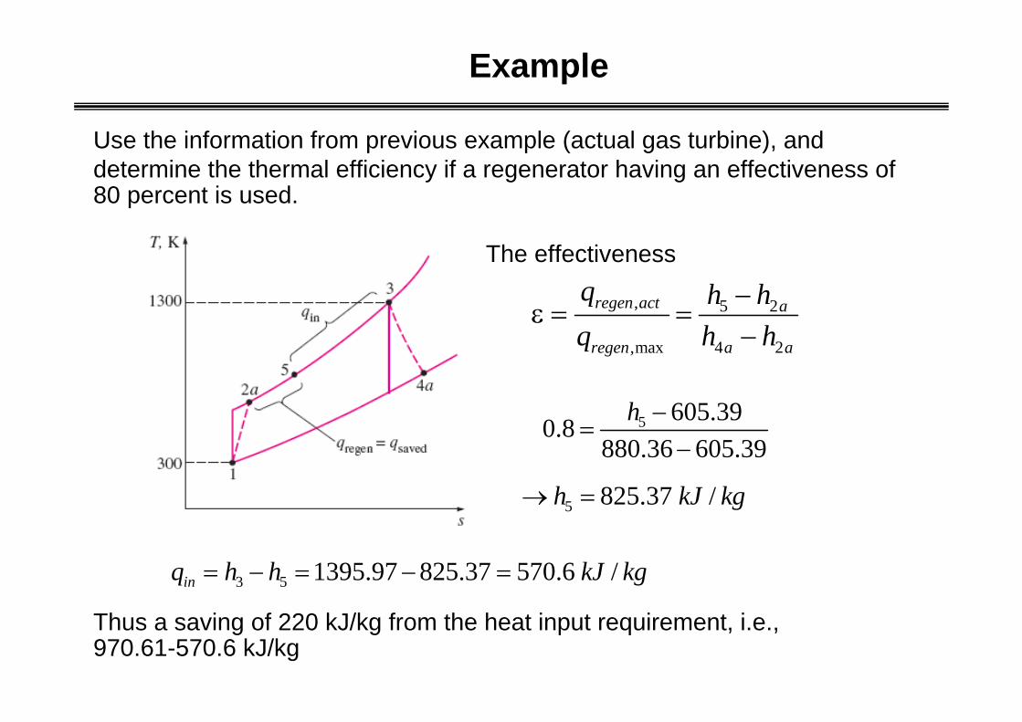
Example
Use the information from previous example (actual gas turbine), and determine the thermal efficiency if a regenerator having an effectiveness of 80 percent is used.
, 5 2
,max 4 2
regen act a
regen a a
q h hq h h
−ε = =
−
The effectiveness
5 605.390.8880.36 605.39
h −=
−
5 825.37 /h kJ kg→ =
3 5 1395.97 825.37 570.6 /inq h h kJ kg= − = − =
Thus a saving of 220 kJ/kg from the heat input requirement, i.e., 970.61-570.6 kJ/kg

,210.41 0.369570.6
netth regen
in
wq
η = = =
0.266netth
in
wq
η = =
With regenerator
Without regenerator

Brayton cycle with intercooling, reheating, and regeneration
Comparison of work inputs to a single-stage compressor (1AC) and a two-stage compressor with intercooling (1ABD)
, ,net turb out comp inw w w= −
• Work required to compress a gas between two specified pressure can be decreased by carrying out the compression process in stages and cooling gas, i.e., multi-stage compression with intercooling.

To determine the intermediate pressure at which intercooling should take place to minimize the compressor work
04 3
2 4
1 31 2
= = compw v dP v dP v dP v dP+ +∫ ∫ ∫ ∫
IntercoolingWhen using multistage compression, cooling the working fluid between the stages will reduce the amount of compressor work required. The compressor work is reduced because cooling the working fluid reduces the average specific volume of the fluid and thus reduces the amount of work on the fluid to achieve the given pressure rise.
For the adiabatic, steady-flow compression process, the work input to the compressor per unit mass is
vdP∫

For the isentropic compression process
[ ]
2 2 1 1 4 4 3 3
2 1 4 3
1 2 1 3 4 3
( 1) /( 1) /
2 41 3
1 3
= ( ) ( )-1 -1
( ) ( )-1 -1
( / 1) ( / 1)-1
1 1-1
comp
k kk k
k kw P v Pv P v Pvk kk kRR T T T T
k kk R T T T T T T
k
k P PR T Tk P P
−−
− + −
= − + −
= − + −
⎡ ⎤⎛ ⎞⎛ ⎞ ⎛ ⎞⎛ ⎞⎢ ⎥⎜ ⎟⎜ ⎟= − + −⎜ ⎟⎜ ⎟⎜ ⎟ ⎜ ⎟⎢ ⎥⎝ ⎠ ⎝ ⎠⎝ ⎠ ⎝ ⎠⎣ ⎦
Notice that the fraction kR/(k-1) = Cp.

For two-stage compression, let’s assume that intercooling takes place at constant pressure and the gases can be cooled to the inlet temperature for the compressor, such that P3 = P2 and T3 = T1.
The total work supplied to the compressor becomes
To find the unknown pressure P2 that gives the minimum work input for fixed compressor inlet conditions T1, P1, and exit pressure P4, we set
dw PdP
comp ( )2
2
0=
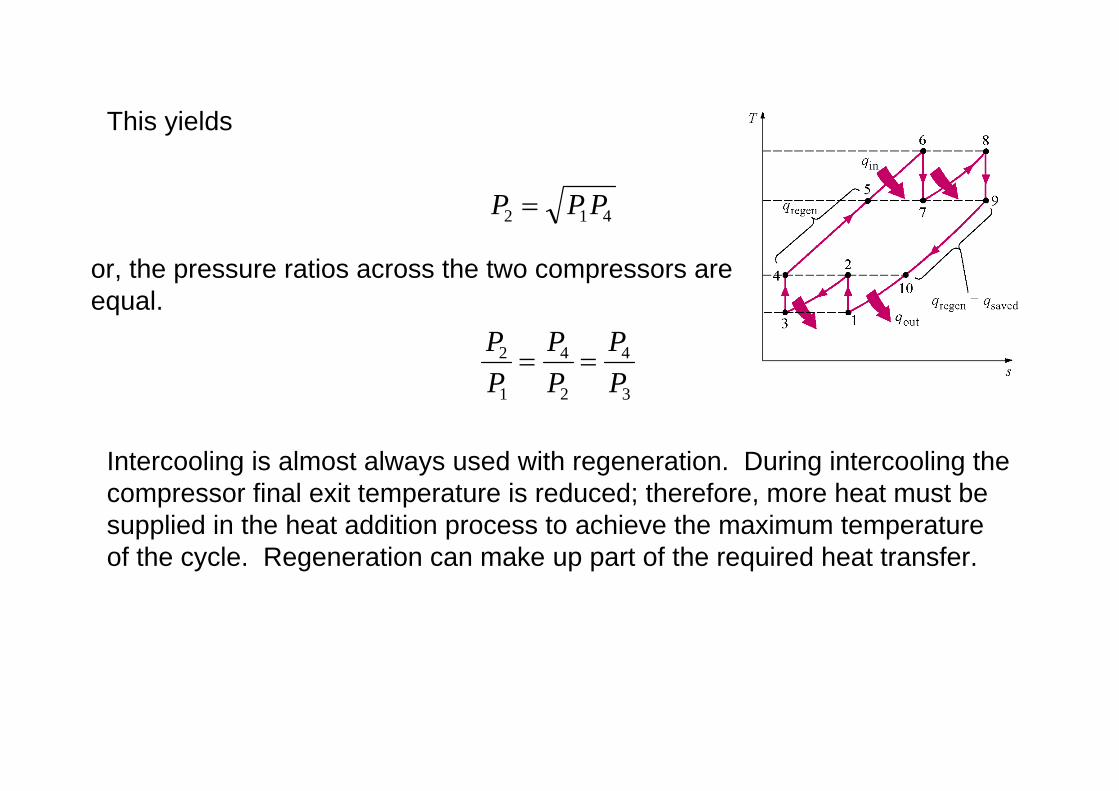
This yields
P P P2 1 4=
or, the pressure ratios across the two compressors are equal.
PP
PP
PP
2
1
4
2
4
3
= =
Intercooling is almost always used with regeneration. During intercooling the compressor final exit temperature is reduced; therefore, more heat must be supplied in the heat addition process to achieve the maximum temperature of the cycle. Regeneration can make up part of the required heat transfer.

A gas-turbine engine with two-stage compression with intercooling, two-stage expansion with reheating, and regeneration
• Work output from turbine can be increased by multi-stage expansion with reheating.
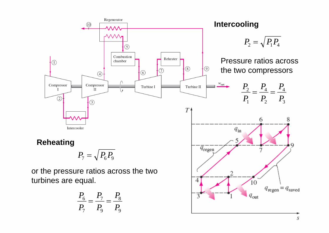
P P P7 6 9=
or the pressure ratios across the two turbines are equal.
PP
PP
PP
6
7
7
9
8
9
= =
Reheating
P P P2 1 4=
PP
PP
PP
2
1
4
2
4
3
= =
Intercooling
Pressure ratios across the two compressors

An ideal gas-turbine cycle with two stages of compression and two stages of expansion has an overall pressure ratio of 8. Air enters each stages of the compressor at 300 K and each stage of the turbine at 1300 K. Determine the back work ratio and the thermal efficiency of this gas-turbine cycle, assuming (a) no regenerators and (b) an ideal regenerator with 100 percent effectiveness.
Example
Assumptions- Assume steady operating
conditions- Use air-standard assumptions- Neglect KE & PE
Overall pressure ratio of 8- each stage of compressor and
each stage of turbine have same pressure ratio
Information

At turbine
Under these conditions, the work input to each stage of the compressor will be same

(a) No regeneration case
Determine the back work ratio & thermal efficiency

From table A-17


(b) Add an ideal regenerator (no pressure drop, 100 percent effectiveness)Compressed air is heated to the turbine exit temperature T9, before it enters the combustion chamber.Under the air-standard assumptions, h5 = h7 = h9

Two stage compression and expansion with intercooling, reheating, and regeneration
Two stage compression and expansion with intercooling, reheating (without regeneration)