me 450 – final report edema swelling measurement device
TRANSCRIPT

ME 450 – Final Report Edema Swelling Measurement Device
December 15, 2010
Team 12
Marty Lueck
Chris Spangler
Kyle Schilling
Eric Zwart

1
ABSTRACT
Accurate Measurement of Edema
Sponsors: Geeta Peethambaran, Physical Therapist Clinical Specialist, University of Michigan Health System Physical Medicine and Rehabilitation Professor Albert Shih, Professor of Mechanical Engineering and Professor of Biomedical Engineering
Description: Edema is swelling caused by excess fluid trapped in the body’s tissues, most noticeably in the feet, ankles, hands, and face. Clinically, there is a great need to accurately measure the level of swelling. The devices currently used are relatively low-tech, including standard, fabric tape measures. Because each person measures slightly differently, inconsistencies are common. Additionally, measuring is tedious because the measurements must be made all the way up the arms and legs. Therefore, there is a need for a device that will both accurately and consistently measure the swelling.

2
EXECUTIVE SUMMARY Design Problem The objective of this project is to design a digital tape measure to be used by physical and occupational therapists to measure swelling in the arms and legs of edema patients. This device is needed to chart the patient’s improvement and to prove to the patient and the hospital that the treatment methods are working.
Customer Requirements and Engineering Specifications Our sponsor, Geeta Peethambaran, is a physical therapist at the University of Michigan Hospital who performs swelling measurements on her breast cancer patients. From her customer requirements, we have generated engineering specifications and have ranked them by importance according to what features she needs the most. Most importantly, our device must provide easily repeatable measurements using a constant tension device. The device must be easy enough to use so that the user can learn how to use it in less than a minute. The product must also be easy to clean to prevent the spread of infections. It must be small enough to fit in the pocket of a standard lab coat and weigh half a pound. The device should have a locking mechanism to allow the tape to stay extended. The measurements taken should be output to an easy-to-read, digital screen that is powered by standard size batteries. See table 1 on page 9 for the complete list and ranking of specifications.
Concept Generation and Final Prototype To ensure that we fulfilled all of our sponsor’s requirements, we decomposed our design by functions and generated ideas which would fulfill our customer requirements for each of these functions. We generated around four to six different concepts for each function. After we completed the concept generation process, we picked the concept for each function that best fulfills the customer requirements and engineering specifications. We did this by weighing the pros and cons of each of the concepts, and then used Pugh charts to compare each of the concepts against each other. The concepts that received the highest score for their function were combined to create our final prototype
Prototype and Final Design Description Our prototype design is similar to our previously created alpha design, but two changes were made. The mechatronics that will take the measurement data is now a rotary encoder, and the locking mechanism now consists of a two wheel system. Our final design for mass production will be much smaller than our prototype because we can use a custom microprocessor board and LCD which will be much smaller than the prototype. The same basic shape and style will be used for both the prototype and final design.
Fabrication Plan and Design Validation We have developed an in depth fabrication plan for our prototype which we used to machine and assemble our components. We have performed several tests of our prototype which allow us to ensure that our customer requirements and engineering specifications have been met. We created a calibration curve to make sure that our prototype is accurate and performed a gage repeatability and reproducibility test to measure its repeatability. Testing showed that our prototype provides accurate and repeatable measurements across users, but is not as repeatable for single users as we would like.
Critique Looking back, there are some places where our design could have been improved. The changes are described in section 10 on page 43. They include changing the position of the power spring, stacking the internal components, using a pinch-locking mechanism, switching to a closed loop measuring device, and creating a bridge piece to hold the locking and tape wheel down during assembly.
Conclusions In conclusion, we have defined the design problem, determined engineering specifications, and created a prototype to solve the problem. We then presented our prototype at the design expo, and tested it to verify that our design provides accurate and repeatable measurements. Finally, we have proposed a final design that will maintain the functionality and accuracy of the prototype while reducing the overall size.

3
CONTENTS Abstract ......................................................................................................................................................... 1
Executive Summary ...................................................................................................................................... 2
Contents ........................................................................................................................................................ 3
1. Introduction ........................................................................................................................................... 8
1.1 Edema background ........................................................................................................................ 8
1.2 Problem Description ..................................................................................................................... 8
2. Customer Requirements and Engineering Specifications ..................................................................... 9
3. Concept Generation ............................................................................................................................ 11
3.1 Tape Material .............................................................................................................................. 11
3.2 Tape Markings for Measurements and Readout ......................................................................... 12
3.3 Looping Tape Designs ................................................................................................................ 12
3.3.1 Fixed Loop Designs ............................................................................................................ 12
3.3.2 Attachable Loop Designs .................................................................................................... 13
3.4 Locking Mechanisms .................................................................................................................. 14
3.4.1 Automatic Locking ............................................................................................................. 14
3.4.2 User Locking ....................................................................................................................... 15
3.5 Constant Tension ........................................................................................................................ 15
3.6 Case Design ................................................................................................................................ 16
3.6.1 Case Shape .......................................................................................................................... 16
3.6.2 Screen Location................................................................................................................... 16
3.6.3 Button Layout ..................................................................................................................... 17
3.6.4 Case Materials ..................................................................................................................... 17
3.6.5 Additional Case Features .................................................................................................... 17
3.7 Mechatronics ............................................................................................................................... 18
4. Concept Selection ............................................................................................................................... 18
4.1 Tape Material .............................................................................................................................. 19
4.2 Tape Markings for Measurements and Readout ......................................................................... 19
4.3 Attachment Method/Tape Layout ............................................................................................... 19
4.4 Locking Mechanism .................................................................................................................... 19
4.5 Constant Tension Device ............................................................................................................ 19
4.6 Case Design ................................................................................................................................ 20
4.6.1 Case Materials ..................................................................................................................... 20
4.6.2 Case Shape .......................................................................................................................... 20
4.6.3 Screen Location................................................................................................................... 20
4.6.4 Button Layout ..................................................................................................................... 20
4.6.5 Additional Case Features .................................................................................................... 21

4
4.7 Mechatronics ............................................................................................................................... 21
4.8 ME 450 Constraints .................................................................................................................... 21
5. Parameter Analysis ............................................................................................................................. 21
5.1 Microprocessor ........................................................................................................................... 21
5.1.1 Basic Functions ................................................................................................................... 22
5.1.2 Additional Considerations ................................................................................................... 22
5.2 Encoder ....................................................................................................................................... 22
5.2.1 Physical Size ....................................................................................................................... 22
5.2.2 Geometry ............................................................................................................................. 23
5.2.3 Counts per revolution .......................................................................................................... 23
5.2.4 Compatibility with microprocessor ..................................................................................... 23
5.2.5 Price .................................................................................................................................... 23
5.2.6 Additional Considerations ................................................................................................... 23
5.3 LCD Screen ................................................................................................................................. 24
5.4 Spool and Locking Mechanism ................................................................................................... 24
5.4.1 Basic Functions of the spool ............................................................................................... 24
5.4.2 Basic Functions of the locking mechanism ......................................................................... 25
5.5 Tape............................................................................................................................................. 25
5.6 Clip .............................................................................................................................................. 25
5.7 Case ............................................................................................................................................. 25
5.7.1 Able to house the internals .................................................................................................. 25
5.7.2 Durable, lightweight, and inexpensive ................................................................................ 26
5.7.3 Ergonomic and easy to hold ................................................................................................ 26
5.8 CES and SimaPro ........................................................................................................................ 26
6. Final Design ........................................................................................................................................ 26
7. Prototype Design Description ............................................................................................................. 27
7.1 Microprocessor [12] .................................................................................................................... 27
7.1.1 Basic Functions ................................................................................................................... 28
7.1.2 Additional Considerations ................................................................................................... 28
7.2 Encoder [13] ................................................................................................................................ 28
7.3 LCD Display [14] ....................................................................................................................... 29
7.4 Spool and Locking Mechanism [6] ............................................................................................. 29
7.5 Spindle Mount ............................................................................................................................. 30
7.6 Tape............................................................................................................................................. 30
7.7 Clip .............................................................................................................................................. 30
7.8 Case [16] ..................................................................................................................................... 31

5
7.8.1 House the internals .............................................................................................................. 31
7.8.2 Durable, lightweight, and inexpensive ................................................................................ 31
7.8.3 Ergonomic and easy to hold ................................................................................................ 31
8. Fabrication Plan .................................................................................................................................. 31
8.1 Designsafe Analysis .................................................................................................................... 31
8.2 Machining Processes ................................................................................................................... 32
8.2.1 Spindle Mount ..................................................................................................................... 32
8.2.2 Plastic Enclosure ................................................................................................................. 32
8.3 Assembly..................................................................................................................................... 33
8.3.1 Install Arduino board .......................................................................................................... 34
8.3.2 Install Optical Encoder ........................................................................................................ 35
8.3.3 Spindle Mount Assembly and Installation .......................................................................... 35
8.3.4 Install the tape wheel and locking wheel ............................................................................ 36
8.3.5 Install LCD and Switch ....................................................................................................... 37
8.3.6 Close Case Assembly .......................................................................................................... 38
8.4 Electrical Fabrication .................................................................................................................. 38
9. Validation Results ............................................................................................................................... 39
9.1 Accurate Measurements .............................................................................................................. 40
9.2 Gauge Repeatability and Reproducibility Testing ...................................................................... 40
9.2.1 Procedure ............................................................................................................................ 40
9.2.2 Results ................................................................................................................................. 41
9.3 Length ......................................................................................................................................... 42
9.4 Ease of Use ................................................................................................................................. 42
9.5 Easily Cleaned ............................................................................................................................ 42
9.6 Robustness .................................................................................................................................. 42
9.7 Locking Mechanism .................................................................................................................... 43
10. Discussion ....................................................................................................................................... 43
11. Recommendations ........................................................................................................................... 44
12. Conclusion ...................................................................................................................................... 45
13. Acknowledgements ......................................................................................................................... 45
References ................................................................................................................................................... 46
Appendix A: Competetive Products ........................................................................................................... 47
Appendix B: Competive Products on the Market ....................................................................................... 49
Mabis Fabric Measuring Tape [5] ........................................................................................................... 49
Myotape Body Tape Measure [6] ........................................................................................................... 49
Digital Tape Measure [8] ........................................................................................................................ 50

6
Metabolism Body Tape Measure [10] .................................................................................................... 50
MyoTape D Optical Digital Tape Measure [7] ....................................................................................... 51
Rackulator [9] ......................................................................................................................................... 51
Appendix C: Gauge Repeatability and Reproducibility.............................................................................. 52
Appendix D: Patent Descriptions and Figures ............................................................................................ 55
Information Sources ................................................................................................................................ 55
Electronic Readout Tape Measure [18] .................................................................................................. 57
Digital Display Tape Measure with Photoelectric Sensing of Tape Displacement [19] ......................... 58
Electronic Digital Tape Measure Having Flexible Measuring Tape [20] ............................................... 59
Hand Held Digital Measuring Device [21] ............................................................................................. 60
Digital Display Tape Measure [22] ......................................................................................................... 61
Digital Measuring Instrument Having Flexible Measuring Line [23] .................................................... 62
Appendix E: Case Design ........................................................................................................................... 63
Appendix F: Reverse Engineering Pictures ................................................................................................ 65
Appendix G: Pugh Charts ........................................................................................................................... 68
Pugh Charts for Tape Design .................................................................................................................. 68
Totals ...................................................................................................................................................... 68
Pugh Chart for Locking Mechanism ....................................................................................................... 69
Pugh Chart for Constant Tension Devices .............................................................................................. 70
Appendix H: Cambridge Engineering Selector........................................................................................... 71
Appendix I: Alpha Design .......................................................................................................................... 73
Appendix J: Bill of Materials ...................................................................................................................... 74
Appendix K: Prototype Materials and Components ................................................................................... 75
Raw Material Inventory for Manufactured Components ........................................................................ 75
Purchased Components ........................................................................................................................... 75
Appendix L: Engineering Drawings of Machined Components ................................................................. 77
Appendix M: Design Changes Since Design Review 3 .............................................................................. 80
Switch ..................................................................................................................................................... 80
Flipped spindle mount ............................................................................................................................. 80
Appendix N: Design Analysis Assignment From Lecture .......................................................................... 81
Functional Performance .............................................................................................................................. 81
Case ......................................................................................................................................................... 81
Encoder Shaft .......................................................................................................................................... 81
Environmental Performance ....................................................................................................................... 81
Manufacturing Process Selection ................................................................................................................ 84
Case ......................................................................................................................................................... 84

7
Encoder Shaft .......................................................................................................................................... 84
Appendix O: Arduino Code ........................................................................................................................ 85
Appendix P: Gantt Chart ............................................................................................................................. 87
Appendix Q: Budget ................................................................................................................................... 88
Appendix R: Team Member Bios ............................................................................................................... 89
Marty Lueck ............................................................................................................................................ 89
Kyle Schilling ......................................................................................................................................... 89
Chris Spangler ......................................................................................................................................... 90
Eric Zwart ............................................................................................................................................... 90

8
1. INTRODUCTION In this section, we will discuss background information on edema, our design problem from our sponsor, and why our design problem is significant and needs to be addressed.
1.1 Edema background According to the Mayo Clinic [3], edema is swelling caused by excess fluid trapped in the body’s tissues. It can affect any part of the body, but it is most common in the hands, arms, feet, and ankles. Signs and symptoms of edema include swelling or puffiness of tissue under the skin, stretched or shiny skin, skin that retains a dimple when pressed, and increased abdominal size. Many complications can arise from edema, including increasingly painful swelling, difficulty walking, stiffness, stretched, itchy skin, increased risk of infection, decreased blood circulation, and increased ulceration and skin breakdown. Edema can be treated by a physical or occupation therapist, or can be treated through lifestyle and home remedies. These remedies include using the muscles around the affected areas, elevating the swollen part of the body, massaging or using compression on the swelling, decreasing the patient’s salt intake, and avoiding extreme temperatures. [3].
Edema is much more prevalent in older age demographics. In the United States, 13% of people age 60-79 suffer from edema, while 17% of people age 80 and over suffer from edema. [4]. The purpose of measuring the circumference of the swollen regions is to allow the physical therapist or patient to monitor the amount of swelling in the region. The measurements of the swollen region are compared to previous measurements to determine whether the current treatment is working. This gives motivation to the patient to let them know that the treatment is working, and these measurements are used to give justification of treatment to the hospital and insurance companies.
1.2 Problem Description Physical and occupational therapists use many different methods to treat edema and reduce the swelling in patients, and will track the measurements of swelling around different regions of patients’ arms and legs. Our sponsor, Geeta Peethambaran, a physical therapist employed by The University of Michigan Health System, has asked us to create a digital tape measuring device to improve the quality, repeatability, and ease of taking measurements of swelling in patients with edema. An accurate method of quantifying the amount of swelling in edema patients is important for three reasons. First, quantifying the amount of swelling can be a big motivator for patients. Treatment plans for edema patients involve exercises can be inconvenient and even painful; if the clinician can prove to the patient that their swelling is decreasing, they will be more motivated to continue working hard at their treatment. Second, measurements are helpful when the patient does not see the same clinician at every appointment. If careful records are kept, then any physical therapist can interpret these records and decide if the current treatment is working or not. Finally, measurements can be used to justify a treatment plan to a hospital or insurance company. Insurance companies are especially interested in seeing quantitative improvement since they are financing the treatment.
Figure 1: Edema affecting the leg and foot [1]
Figure 2: Edema affecting fingertip, as compared to a non-affected digit [2]

9
As is the case with many medical treatments today, there is no standard procedure taught or used across the board for measuring edema. Our sponsor explained to us the procedure she currently uses; she marks the patient’s arm or leg every 5 cm, taking measurements at those points, and comparing them to previous measurements to see if treatment is working. Our sponsor stated that a similar method is used by most of the physical therapists working at the University of Michigan hospital, but that this was not likely true at other hospitals and medical centers around the nation. Two problems with the current method exist. First, the person taking the measurement must provide the tension on the tape to hold it taut against the skin. If different people take measurements at the same point on the body and apply different amounts of tension, then the measurements are inconsistent. Devices that provide constant tension, such as the MyoTape device discussed later in this paper, are available on the market, though they are not commonly used because they do not provide measurements as accurately as a standard cloth tape measure. The MyoTape is not as accurate simply because it is difficult to discern exactly from where the measurement should be read, causing inconsistencies when different people use the device. This is discussed in more detail in the GR&R section of Validation on page 40. Second, the current system uses a cloth tape that can be difficult to read, and many patients could have difficulty getting accurate measurements at home. Because of these issues, we have been asked to design a device to take these measurements that provides a constant tension on the tape while measuring. This device must be easy to use so that medical staff and patients can perform accurate, repeatable measurements. The device must also have an easy-to-read, digital display to show the length of the measurement.
2. CUSTOMER REQUIREMENTS AND ENGINEERING SPECIFICATIONS Using the project requirements we collected from our meetings with our sponsor, we established a set of engineering targets for our measuring device. As you can see from table 1, we ranked the different project requirements in importance according to our discussion with our sponsor and internal discussions in the group.
Table 1: Ranking of the customer requirements and how they translate into engineering specifications. 5 is highest importance, 1 is lowest. Customer Requirement Importance Engineering Specification
RE
QU
IRE
D
Accuracy of measurements 5 Must accurately measure circumference of arms and legs to the nearest ½ mm
Repeatable measurement 5 Must have a constant tension device. Tension force must be 8 N
Metric Units 5 Must display measurement in cm Length 2 Must be 200 cm Ease of Use 4 Proficiency within 1 minute of self-training Easily cleaned 5 Cleaned with alcohol pad in 30 seconds
Size (fits in coat pocket) 4 Should be approximately 12 cm x 10 cm x 5 cm and weigh less than 1/2 lbs
Robustness 3 Withstand 5 drops from 1 meter Standard Batteries 2 Must use standard watch battery Locking mechanism 2 Withstand 8N
OPT
ION
AL
Stores data 3 Store 150 measurements and output a text file to a computer for ease of recording
Cost 2 Costs less than $50
No metal, plastic only 2 Made of plastic, not metal, for patient comfort Different colors 1 Available in different colors

10
Because some of the customer requirements were yes or no features, we were unable to specifically quantify them. For the other requirements, we generated engineering specifications by interpreting what our sponsor told us about her job, studying competing products, and making judgments which must be verified later. Geeta has reviewed our engineering specifications and has agreed that they are satisfactory quantifications of her requirements.
To translate the accuracy of measurements requirement into an engineering specification, we studied the devices that Geeta Peethambaran is currently using, both of which have a resolution of 1 mm. She said that she does not record measurements to the millimeter; more often she records to the half a centimeter. We feel that we can make our device accurate to 0.05 cm, which may be useful for other tests performed in the hospital. For repeatable measurement, we will use a constant tension device. We have done testing on some of the devices on the market using a spring force gauge and determined that the average force of power springs is 8 N; therefore, our device will use a similar power spring with 8 N of force.
To translate the length requirement into an engineering specification, we studied the devices that our sponsor currently uses to measure patients. Both of the measurement devices she uses have a maximum length of 150 cm. For some of the larger patients, 150 cm is too small to comfortably fit over the patient’s thighs. To improve on these designs, we must design a tape measure which can measure a circumference of 200 cm.
For the ease of use requirement, we have decided that we will conduct a study once our prototype is complete that will gauge if the participants can become proficient in using the device to take measurements with only 1 minute of self-training. The device should be so straightforward that there is virtually no learning curve or training time. To ensure that the tape can be easily cleaned, we will conduct a test to make sure it can be cleaned with an alcohol pad in 30 seconds or less. We timed how long it took our sponsor to clean the tape she uses and adopted the same specification since she said the current cleaning system is adequate.
The tape measure must be reasonably sized so that it can be carried in the pocket of a lab coat. It must also be lightweight so that measuring is not difficult. To generate approximate dimensions, we considered the sizes of our cell phones. The length and width of the phones felt appropriate, so we approximated 12cm by 10cm. For the thickness, we considered standard tape measures on the market and took their thickness of about 5cm. This should leave us enough room for the tape windings, the battery case, and other electrical components, while remaining easy to hold. For the weight, we considered how much weight is easy to carry and move around while measuring arms and legs. We decided that half a pound is a reasonable weight specification, but it is currently considered as a flexible engineering specification because we do not know how much the components will weigh. Our goal is to minimize the size and weight as much as possible.
Robustness is difficult to quantify. We decided that clinicians are most likely to be using the device within 1 meter of the floor because patients are usually seated when taking measurements. Because of this, we will conduct testing on our device to ensure it does not break over the course of 5 drops from 1 meter onto tiled flooring similar to what is found in hospitals. If our device uses a battery, they must be either AAA or a standard sized watch battery for the convenience of the user. The locking mechanism on the device is used to prevent the spring from pulling the tape back into the device unless it is purposely released by the user. Through testing, we determined that the spring force of the competitors’ products is approximately 2.66 N. We must make sure that the lock is able to withstand the force of the torsion spring with a safety factor of 3, meaning that it must withstand a force of 8 N.
The optional category of the project requirements are things that our sponsor told us that she would like to see, but are not necessary for the completion of the device. Again, these features are not product requirements or engineering specifications; however, if time permits, we will include as many as possible.

11
Essentially, these requirements will be in the back of our mind while designing, but will not dictate success or failure of the product. Cost is an optional project requirement. We believe that less than $50 is an appropriate benchmark. Doctors and patients are not going to be paying for these devices; insurance companies and hospitals will and they are not as concerned with the cost as a patient would be. If possible, our sponsor would like the tape measure to be made of a material other than metal. Some of her patients complain about metal instruments being uncomfortable because they are cold. She wants her patients to be comfortable, so she would prefer a plastic case. Finally, our sponsor thought it would be a good idea if the tape measure came in different colors. This would be more for the home user than the hospital. Being able to pick a favorite color would hopefully entice users to pick our product over a similar device.
One optional customer request that we will not be able to complete this semester is storage of the last 150 measurements with the option of exporting the measurements to a computer via USB or portable data card. This feature would make the task of the medical staff much easier since they would not have to stop after every measurement to write down the value. Saving the data would not be too difficult because the Arduino microprocessor we are using has adequate memory to store a day’s worth of measurements; however, we will not be able to design such a feature because of the time constraints placed on us and our lack of knowledge in dealing with complicated electronic and computer systems. Adding this feature on to our device is a potential project for a future senior design group in mechanical, electrical, computer, or computer science engineering.
3. CONCEPT GENERATION After researching patents, products available on the market, and quantifying our customer requirements into engineering specifications, we began the process of generating different ideas for each of the functional categories of our proposed tape measure.
3.1 Tape Material While brainstorming ideas for different possible tape materials, we discussed five different options (see figure 3 below). The first option is to use a vinyl tape that is ¾” to 1” wide, similar to the tape used in the MyoTape. The tape would be white and have black markings to the nearest mm. A second option is to use a very thing string or wire-like line. The string would be white in color and would use black markings for measurement. This material would be more difficult to translate the measurement to the digital readout since it would not have a flat surface for us to print the encoding pattern on.
Figure 3: Possible tape materials
A third option is to use a thin rope-like material approximately ¼” thick. Like the vinyl material, this material could be imbedded with a resistor to provide the digital readout. A fabric tape could also be used. The problem with fabric tape is that the material may absorb fluid from the skin. This would be a poor
Thin Vinyl (≈1/4 in.)
String
Fabric
Thick Vinyl (≈ 1 in.)

12
material choice since patients may have open sores and would be extremely difficult to clean. Another option for tape materials is to use a chain. The chain would be converted to a digital readout by a mechanism that would count how many links has passed by. This material is not probable to be used because it would be uncomfortable for patients suffering from painful swelling.
3.2 Tape Markings for Measurements and Readout We must also design a method for the tape length to be converted to the digital readout screen (see figure 4 below). For the vinyl and fabric designs, a dot pattern could be printed onto the tape, and then read by an optical encoder to determine how far the tape is extended. There would be different markings for inches and cm. For instance, inches could be placed on the bottom of the tape, with cm on the top. We could also use a light sensor instead of an optical encoder to read the measurement, replacing the dot pattern with holes in the tape optical encoder. The third option applies only to the vinyl tape or rope materials and would include embedding a resistor in the material. When the tape extends, the total resistance of an internal circuit would change, and this resistance would be converted into a measurement on the digital display. The thin, rope-like design and the string design would both require a pattern to be marked on them to be read by an optical encoder. The readout would only be digital because there would not be room to put markings on the tape for inches, cm, and mm. This could be a problem if the user were to run out of battery power while taking measurements and did not have a spare battery on hand.
Figure 4: Possible tape designs
3.3 Looping Tape Designs The main function that our device must accomplish is to accurately measure the circumference of a patient’s swollen arms and legs. Different methods will provide more or less accurate devices. We used our best engineering sense to decide which method we believe would have the most accurate and repeatable measurements method. We thought of two broad ideas of how to do this and then generated more concepts from the main two ideas. The two main ideas are fixed loop and attachable loop. A fixed loop would only measure circumference whereas the attachable loop would be able to measure linear distances as well as circumferences. We feel that the fixed loop would give more accurate circumference measurements than the attachable loop design, but the attachable loop design is more versatile and might be more useful for our customers.
3.3.1 Fixed Loop Designs Our first idea of how to accomplish the fixed loop design is similar to the MyoTape design except fixed at the top instead of an insert (see figure 5(a) on the next page). We feel that the most accurate way to get the circumference measurement is to minimize the distance between the fixed part of the tape and the tape opening. The case will not bend around the arm or leg since it is most likely going to be made of plastic. Maximizing the amount of tape would be the most accurate method since the tape will bend, giving a more accurate measurement.
Another idea we had which would incorporate a fixed loop is the two spindle design (figure 5(b) on the next page). The two spindles would allow flexibility for circumference measurement. The user would be able to pull either end of the tape to extend for measurement. The downside to this design is that we would need a more complicated locking mechanism and the increased possibility of jamming or breaking since there will be more moving parts. It would need two spindles and two constant tension devices. It
Encoded strip with inches and centimeters marked
String with markings down length

13
would also be more difficult to design a counter to digitally display the distance that the tape has been extended.
Figure 5 (a),(b): Fixed Loop Designs (a) Single spindle fixed loop (b) Double spindle fixed loop
3.3.2 Attachable Loop Designs To give our tape measure the ability to measure straight line distances as well as circumferences, we came up with a series of concepts which used an attachable loop design.
The first attachable loop design we came up with uses magnets; one at the end of the string or tape and one in the case where the tape would connect to form the loop (see figure 6). This could be a very effective design if we can use the magnet contact to tell the device what measurement to take. If possible, the magnet contact would complete a circuit which would tell the device to add the distance between the opening and the magnet connection automatically. That way it would measure circumference if the magnets were connected or straight line if they were not. If we end up using this design, we must make sure to use strong enough magnets so that they will not come unclipped from normal use, but not too strong so that the user could not get them apart for linear measurements.
Figure 7 (a), (b), (c): Attachable loop designs (a) Press-fit loop attachment (b) Self-clipped tape design (c) Tape clip in use
The next attachable loop design we came up with builds upon the MyoTape’s design. The Myotape has a cylinder on the end of the tape which fits into a hole on the other side of the case. This allows the user to measure straight lines as well as making it easier to measure large circumferences since you can just clip the tape around the arm or leg instead of having a fixed loop. The problem with the Myotape’s design is that the cylinder falls out too easily during normal use. To fix this, our idea is to use a T-shaped slot to
Figure 6: Magnet attachable loop design

14
secure the rod at the end of the tape (see figure 7(a) on the previous page). This should allow easy attachment of the loop as well as keeping the looped securely fastened while the user is measuring a circumference.
Our other idea for the fixed loop design uses a clip at the end of the tape which would attach back onto the tape, completing the loop used for the circumference measurement (see Figure 7(b) and (c) above). This design would be very simple and easy to use. The difficult aspect of this design will be designing a clip which fastens strong enough so that it does not slip during normal use and is robust enough not to break. If the clip breaks on this design, then the device will not be able to fulfill its main purpose of measuring swelling in the arms and legs of patients.
3.4 Locking Mechanisms One of the customer requirements is the tape must lock in the extended position. It is important that the device is capable of locking because it allows the user to more easily operate the device. We have looked at multiple tape measures on the market to determine which type of locking mechanisms they use, and then used these basic designs to generate concepts of our own. The two main concepts for locking mechanisms we generated are automatically locking and user locking.
3.4.1 Automatic Locking In an automatically locking design when the tape is extended it will not automatically retract. Instead the tape stays locked in the extended position until the user pushes a button to retract the tape.
Figure 8(a), (b): Auto-locking wheel (a) Top view (b) Side view
Our first concept for a locking mechanism is commonly used in fabric tape measures. It incorporates a power spring, a wheel (which the tape is wrapped around), a spring, and a push button. A concept of a wheel that could possibly be used can be seen in (Figure 8). Inside of the wheel there is a power spring that applies force as the tape is extended. When the tape is extended, the wheel turns and is able to lock after every quarter turn. In order to lock the tape in the extended position, it contains four teeth that are stopped by the bars on the push button. When the user wants to retract the tape, they have to push the button which will allow the tape to retract into the case
Figure 9(a), (b): (a) Top view of pin locking mechanism (b) Side view showing pin inside of hole in tape
The second concept we generated for this type of locking mechanism uses a tape with holes in it and a stopping pin. As the tape is extended the pin stays in the holes that are in the tape preventing the tape from automatically retracting. It will have a pin that is attached to a spring that will be aligned with the

15
holes in the tape as seen in figure 9. In order to retract the tape, the user has to push the button which causes the pin to vacate the holes and allows the tape to retract into the case.
3.4.2 User Locking In a user locking design when the tape is extended it will automatically retract unless a lock button is pushed.
Our first design for this method uses a concept that is found in hard tape measures. It uses an applied force to stop the tape from retracting. A concept of a design that could possibly be used can be seen in figure 10. After the tape is extended the user can press the button on the top of the tape measure which applies a force to the tape. The force that is applied will be enough to stop the tape from retracting. The tape will retract back into the case when the button is pressed to release the force.
Figure 10: Pinch locking mechanism Figure 11: Magnet locking design
The second concept we generated for this type of locking mechanism uses magnets to hold the tape in the extended position. This design uses an electromagnet and a permanent magnet combination. When the user pushes a button, the electromagnet is electrified and the pair of magnets clamp down on the tape, effectively locking it (figure 11). To retract the tape, the user simply pushes the “lock” button again, the electromagnet is un-electrified, and the tape is released.
3.5 Constant Tension Our tape measure must have a constant tension device so that it can provide accurate and consistent measurements regardless of user.
The standard method for generating constant tension in tape measures is to use a power spring, which is basically a roll of thin, metallic tape as you can see in figure 12 on the right. As the measuring tape is extended, tension increases. When the user releases the lock, the tape slides back into the case. Our concept would use the same method.
Another idea we have to generate the constant tension in our design is to use a linear spring (see figure 13(a and b) on the next page). The spring would be attached to the non-measuring end of the tape. It would have to be offset from the tape though to allow the wheel to spin fully.
Figure 12: Thin, metallic tape which generates the constant tension in the Myotape

16
Figure 13 (a), (b): Linear spring constant tension design (a) Side view (b) Top view
Our last idea for generating the constant tension does not actually use a constant tension device. We would use a DC motor (figure 14 below). We would have in and out buttons on the case and the user would operate the tape measure that way. There are some problems with using a motor however. The motor would have to be slow on the way in to prevent users from pinching themselves with the tape. It should also use some sort of safety device to make sure that the motor would quit drawing the tape in once it was taut around whatever it is measuring. The motor would also make it more difficult to draw the tape out to its full length compared to just using a standard constant tension device.
Figure 14: DC Motor design
3.6 Case Design 3.6.1 Case Shape We proposed many different shapes for our design based on the many different features that were proposed. The most important aspects of the shape is that the case is ergonomic and easy for the user to hold and that there is a radius of curvature on the measuring end of the case so that it can sit flush with the patient’s skin to ensure the most accurate measurement. This radius must be one that allows for accurate measurement of many ranges from smaller portions of the arms, to the largest parts of the legs. The rest of the shape for the case will be determined by which design allows for the best fit of the internals of the tape measure. See appendix E for all proposed shapes.
3.6.2 Screen Location The design for the location of the digital display will depend largely on the design chosen for the case shape. There are three proposed designs for the screen location: on top of the case, on the right/left side of the case, or dual screens located in any two of those locations. Figure 15 shows the dual screen layout that includes a screen on both the top and side of the tape measure. See appendix E for sketches of
Figure 15: Button layouts and screen locations

17
all screen location proposals.
3.6.3 Button Layout We must decide what features on the device will require button functions to be used. Proposed features for button layouts include a power button, an inches/cm display button, a tare button to zero the display, a front/back button to show where the device is measuring to, and a retract button used to pull in the tape. We must decide which of these features/buttons are necessary, and where the necessary ones will be located on the case. Figure 16 below shows one of our proposed button layouts. See appendix E for sketches of all proposed button layouts.
Figure 16: Top screen position and button layout
3.6.4 Case Materials We discussed many options for the material that will be used to create the case for our tape measure. The first material that we discussed was plastic. Plastic would be durable enough in case the tape measure was dropped, is easy to machine, and should not cause discomfort to the patient. We also discussed using various types of metal for the case, mainly aluminum and steel. These materials are much stronger than plastic and would be more durable, but they would be heavier. Metal also feels cold to the patient’s skin which could cause discomfort. The final material that we discussed for our case was wood. Wood would be heavier than plastic but lighter than metal, and is easy to machine. When using wood, there is always a danger for splinters to develop, which could get stuck in the patients skin and cause further complications. Therefore, wood is not a viable option.
3.6.5 Additional Case Features We also discussed two additional features to include with the case of our product. The first feature is a carrying strap that will be looped on to the case. This feature will allow the used to loop the case on to their wrist and will greatly reduce the chances of the device being damaged by falling to the floor if it is dropped. The second feature we discussed is a belt clip. This would allow the user to clip the device onto their belt or to the inside of their coat pocket for when they are travelling around the hospital to see different patients. See figure 17 for sketches of our proposed designs.
Figure 17: Additional case features, carrying strap and belt clip

18
3.7 Mechatronics Our concept must be able to digitally display the measurement of the extended tape. In order to do this, it must use some form of mechatronics. After reverse engineering similar products and researching other possibilities, we have generated three different concepts that are capable of digitally displaying the measurement.
Our first concept came from reverse engineering the electronic digital tape measure (eTape), see appendix F. The eTape uses an optical encoder in unison with its marked metallic tape. As the tape is extended, incremental measuring data (which comes from the optical encoder sensing the markings on the tape) is collected by the processing unit which generates an output to send to the digital display. One of the challenges with implementing this concept is being able to print the markings on a flexible tape. Possible solutions to this problem include: using an inkjet printer, a laser cutter, or having a third party complete the task.
The second concept we generated uses a multi-turn potentiometer. The potentiometer will be connected to internal wheel that the tape is wrapped around. As the tape is extended it turns the internal wheel which causes the resistance of the potentiometer to increase. The potentiometer will be connected to a circuit with a microprocessor that will be capable of making the calculations to determine the extended length of the tape. A challenge with using this concept is that the accuracy of the measurements will be limited to the accuracy of the potentiometer we choose.
Our third concept uses a long, wire potentiometer embedded in the flexible tape. This concept is similar to using a potentiometer inside the case because as the tape is extended, the resistance increases. The tape will have to be attached to specific spot on the case to complete a circuit. Once the circuit is completed, the microprocessor will make calculations based on the voltage left after traveling through the resistor to determine the extended length of the tape. One of the challenges associated with this design is that a wire must be placed along the entire length of the tape. It may also be difficult to provide accurate measurements at longer lengths. The accuracy of the measurements will depend on the accuracy of the potentiometer we choose.
4. CONCEPT SELECTION After generating concepts, we used a combination of Pugh charts and debate amongst the team members to decide which concepts were most likely to help us meet our customer requirements and engineering specifications. All of the Pugh charts we used can be found in appendix G. Table 2 below shows which concepts we chose for each functional category.
Table 2: Concepts selected based on Pugh chart analysis and intra-team discussion Function Concept Chosen Reason Tape Material Laminated Vinyl Strong, easy to clean Tape Markings Repeating optical encoder
pattern; centimeter units Prescribed by our use of an optical encoder to digitize our device
Attachment Method Lasso/Clip Method Highest score in Pugh chart Locking Mechanism Auto-Locking Wheel Highest score in Pugh chart Constant Tension Device Power Spring Standard use in most tape measures Case Material Plastic Meets customer requirement of no metal Case Shape Rectangular, rounded
edges and corners Form follows function
Screen Location Top of the case Allows the user to see the Additional Case Features Wrist strap Clip was not necessary since it will be
put in a lab coat, wrist strap was positively received by sponsor

19
Mechatronics Optical encoder plus potentiometer
Optical encoder is primary measurement device, backed up by potentiometer if device is shut off while tape is extended
4.1 Tape Material We decided to use a standard vinyl tape for our tape measure. The vinyl tape is the best choice for our product because it is very inexpensive, easy to clean, and will not cause the patient discomfort while measurements are being taken. The vinyl tape also did not have any cons to go along with its pros, while the other suggested materials did. The rope material would be very difficult to wind because it is much thicker than the vinyl. The chain material would have been very uncomfortable for patients with painful swelling. Finally, the thin string material would be very flimsy and could break very easily if pulled on too hard. The vinyl tape did not have any of these problems and because it is also inexpensive and easy to clean, it is the clear choice for our tape material.
4.2 Tape Markings for Measurements and Readout We decided to have our tape show centimeters and a repeating pattern for the optical encoder to read. We are displaying centimeters so that the user will still be able to take measurements even if they run out of batteries.
4.3 Attachment Method/Tape Layout We created a Pugh chart (see appendix G) to aid us in our decision for what attachment method would be best for creating the loop that will measure the patient. From this Pugh chart, we decided that best method for measuring the patient would be to use a lasso type method created by a sliding a clip on the end of the tape over the tape itself and retracting the excess tape to create a loop. A sketch of our chosen attachment method is shown in figures 7(b) and 7(c) on page 15. The other methods that were suggested had many drawbacks and were deemed inferior options for an attachment method. Examples of these drawbacks include the fixed loop and two spindle methods were too costly and difficult to sanitize between patients, the key design was not as easy to use, nor was it as robust, while the magnet method was deemed to contain many of the same positives as the lasso method, but ultimately was slightly inferior.
4.4 Locking Mechanism To decide which locking mechanism we are going to use for our design, we created the Pugh chart in appendix G comparing our different ideas against the auto-locking wheel design used in the MyoTape and standard cloth tape measure device. The design characteristics we evaluated the different concepts on were robustness, reliability, accuracy of measurements, ease of use, and cost.
Robustness – it should be strong enough to hold up against normal use Reliability – it should stay locked when the user locks it Accurate measurements – it should make reading the measurements easier, not more difficult Ease of use – any user should be able how to figure out how to lock it Cost – it should be cheap to produce
As you can see from the Pugh chart located in appendix G, we feel that the auto-locking wheel design and the pinch locking design are the two strongest locking mechanisms, with the auto-locking wheel being slightly better.
4.5 Constant Tension Device To evaluate which constant tension device would be best for our design, we used a Pugh chart, see appendix G. We used the power spring as the datum since it is used in the MyoTape and the standard cloth tape measure. We compared the power spring to our other concepts; the linear spring and the DC motor. We compared the three concepts based on four design criteria: cost, easy to implement, easy to manufacture, and easy to use.

20
• Cost – should be cheap • Easy to implement – should be easy to design a way to use the constant tension device • Easy to manufacture – should be easy to put the constant tension device into the device • Easy to use – should be easy for the end user to use the tape measure with the constant tension
Using the results generated from the Pugh chart, we have decided to use the power spring for the constant tension device in our prototype. The power spring should be the cheapest and easiest to implement into our design. It is slightly more difficult to assemble and to use when compared to the DC motor but overall, it is still more effective as a constant tension device than the other two concepts.
4.6 Case Design We feel that the case design will be based almost entirely on the internal workings of our device. We want to make the shape as simple as possible to make it easy to manufacture and aesthetically pleasing.
4.6.1 Case Materials We discussed the three proposed options for the material that the case will be constructed from. These materials included plastic, metal, and wood. Because wood is not very durable and can have a tendency to splinter, it is not a viable material. Our sponsor also asked for the case to be made of something other than metal because she has had patients complain that metal instruments feel cold and uncomfortable on their skin, so we will not use metal to construct the case. We decided that plastic is a good option for the case because it is durable, lightweight, easily machined, and will not cause any discomfort to the patient, therefore it is the material that we will use for the case.
4.6.2 Case Shape Because we are using the lasso method for completing the measurement loop, there will not be a need to create a radius that will sit flush against the patient’s skin. The case must be ergonomic so it is easy to hold and must hold all of the internal pieces of the tape measure. A rectangular case design will maximize the amount of space inside the case for the internals while still allowing the case to be ergonomic and easy to hold. We will make the edges of the case smooth so that there are no sharp corners or edges that could scratch or poke the patient.
4.6.3 Screen Location Because we will be using the lasso method for providing measurements and a rectangular case to house the internals, we used the case of the eTape to simulate taking a measurement. We found that the easiest place to read the screen would be on the top side of the case. We also decided that a dual screen design is unnecessary and would only drive up the price of our device; therefore, we will be using a single screen that is located on the top of the case.
4.6.4 Button Layout We discussed the proposed button features and the layouts for these buttons to decide what features are necessary and how to create a user friendly location for these buttons. We have decided to include a button to turn the device on and a button to release the auto locking mechanism so that the tape can retract. The power button will be placed on top of the device and will be located next to the digital display. The retract button will be located on the side of the device so that it can easily be pressed by the user’s thumb while taking a measurement. We decided to only display the measurement in cm, so and inches/cm button is no longer a necessary feature. Also, because the lasso method of measurement will be used, there is no longer a need for a front/back measurement button since it will only be possible to measure to the front of the case because there is no fixed loop measurement. Finally, we decided that we will include a tare button on the top of the case next to the digital display. We feel that this is a necessary feature because it can be used to zero the digital display when the tape is fully retracted so that the optical encoder will start reading from the proper measurement point.

21
4.6.5 Additional Case Features After discussing the two additional case features that were proposed for our design, we have decided to include a carrying strap, but we will not include a belt clip. Our sponsor asked us to include a carrying strap that could go around the user’s wrist if possible, and we believe that this feature will be useful to the people who are using the device. We decided not to include the belt clip because the device will be small enough that it can easily fit into the pocket of a lab coat, therefore a belt clip is unnecessary and would be used very rarely.
4.7 Mechatronics After taking apart the eTape and researching the other concepts generated, we first decided to use a combination of a potentiometer and an optical encoder design. We believed that a combination design would be easier to implement than the other concepts and it would be able to provide accurate measurements, but after performing more research he have decided to instead use a rotary optical encoder.
For the original design, one positive is that it is able to determine the absolute position of the tape. This means the tape does not need to return to zero after every use. The cons to using a combination design are that it will be expensive to purchase a customized measuring tape, potentiometers are inaccurate, and it will have to use additional mechanical components to turn the potentiometer. The addition of mechanical components increases the chance that the tape measure will fail mechanically.
Our prototype design now incorporates a rotary optical encoder to determine the length of the extended tape. It is important that we choose an optical encoder with a high enough resolution to get the accuracy that the engineering specifications require. The rotary optical encoder will be connected by a shaft to the tape wheel, so as the tape is extended it turns the optical encoder. When the shaft spins, the encoder sends the data to the Arduino board where the calculations are made to determine the extended length. We believe that a rotary optical encoder will be easier to install than a combination design and will provide us with a more accurate measurement. The major drawback for rotary optical encoder design is that there is no way to determine the absolute position, so the tape needs to be returned to zero after every measurement.
4.8 ME 450 Constraints Our prototype was influenced mostly by the time constraint associated with the class. If we had time, we would have learned more about circuit board design. With this knowledge, we could have manufactured our own custom made board instead of using the Arduino Duemilanove which would have reduced the size of our case, reduced the battery power required, and gotten rid of the DC to DC converter. With our own custom made board, we could have purchased a more precise encoder which would have increased the accuracy of our measurements.
5. PARAMETER ANALYSIS Once we decided on which design we will use, we used engineering analysis to help us decide which components and what types of materials should be used for this specific application.
5.1 Microprocessor The microprocessor is the brain of the entire mechatronic system; it gives instructions to the encoder and tells the display what to output. Choosing a microprocessor can be difficult because of the sheer number of them on the market. Because of our limited electronic knowledge, we should choose a microprocessor that is simple and has the largest amount of support from our GSI, professors, and even the internet.
Our microprocessor must have three basic functions:
• Power the optical encoder

22
• Process the data from an optical encoder • Output the data to an LCD screen
Additionally, we must consider:
• Size of the board • Heat generation • Price
5.1.1 Basic Functions To assure that our microprocessor is well-suited for our project, we must consider the functions that we expect it to perform. First, the microprocessor must be able to power the optical encoder. If the microprocessor is not able to power the encoder, we will need to purchase an additional driver to power the system. This will not only significantly complicate the circuitry, but it will also make the overall size of our device larger and make it more expensive. The microprocessor must also be capable of processing the data from the optical encoder. We will need to purchase a board that has at least as many digital input/output (I/O) pins as channels on our encoder. The encoder will likely have either two or three channels. Finally, the board must also have enough I/O pins to output the data to an LCD screen. Depending on the screen we choose to use, this will likely require three I/O pins.
5.1.2 Additional Considerations The microprocessor must fit inside whichever case we choose to use; however the case size is flexible. If we find a microprocessor that will perform all the basic functions well but is too large, then we will likely increase the size of the case for the sake of simplicity. The board should not exceed 10 cm x 7 cm x 3 cm in order to satisfy our customer requirement of 12 cm x 10 cm x 5 cm. We must also consider the heat that the microprocessor will generate. If too much heat is generated without dissipation, the board will overheat and malfunction. We spoke with Dan Johnson, who has significant experience with Arduino and mechatronics, and he told us that heat should not be an issue with the small amount of current that we intend to use; this is an adequate level of analysis for this parameter. Finally, we must stay within budget for this project. Looking at the microprocessors on the market, we have decided that we will be able to find one that costs less than $50.
5.2 Encoder When we first looked at what type of encoder we needed to use, we decided on several parameters that were most important for the success of our design:
• Physical size • Geometry • Counts per revolution • Compatibility with microprocessor • Price
The product with the best combination of these characteristics will be used in our final design. This section will discuss how we used analysis to determine which encoder we chose to use.
5.2.1 Physical Size We needed to choose an encoder that both fits inside our case and also will provide enough room for the rest of the components, including the microprocessor, battery, and the tape and locking mechanism. We also have a constraint on the maximum size of the entire tape measure: it must fit inside of a lab coat pocket. Maximum size, therefore, is only 12 cm by 10 cm by 5 cm. Unfortunately, because of the size of the microprocessor that we are using (Arduino Duemilanove), the actual case we are using is going to be larger than our original goal, with miniaturization coming before the product is mass produced. The case

23
we are using has outside dimensions of 6.88” x 4.88” x 2.51” (approximately 17.5 x 12.4 x 6.4 cm), which leaves us plenty of room to house our encoder and all the other components.
We have chosen to stack our encoder and the spinning tape wheel on the same vertical axis. Because the tape wheel is 0.59” tall, we looked for encoders that are vertically shorter than 1.7” since the inside height of our case is 2.3”. The other dimensions of the encoder are less important since the most of encoders that are so thin will also have a small enough footprint to fit inside with room to spare.
5.2.2 Geometry The geometry of the encoder is important because we intend to affix the rotating spindle of the tape measure directly to the inner race of the encoder. We therefore need an encoder that has an inner diameter that is satisfactory for attaching the spindle to rotate the entire system and count the amount of rotations the tape is extended. We have determined that the shaft currently used in the MyoTape is only 1.0 mm in diameter; therefore, we will find an encoder with an inner diameter of at least 1.0 cm. We believe this is sufficient rationale since the current system works flawlessly. No further analysis is necessary.
5.2.3 Counts per revolution The counts per revolution determine the resolution of the measurement to be taken. The larger the diameter of the spool of tape, the less precise the measurement will be. In order to satisfy our engineering specification of a resolution of .05 cm, we will need to make sure that the encoder has at least 377 counts per revolution, as according to the equations below. The maximum diameter of our spool will be 6 cm.
Diameter: 6 cm 18.850 cm18.850 cm / 0.05 cm 377 counts per revolution
π =
=
5.2.4 Compatibility with microprocessor Because we have limited experience with mechatronics, we have decided to use a simple Arduino Duemilanove board and microprocessor. They have the most support and are relatively simple to program. The alternative to using an Arduino microprocessor is designing a custom microprocessor specifically for our application. In speaking with Dan Johnson, our graduate student instructor, he suggested that this process was too complex, time-consuming, and expensive for the constraints of this project. We are therefore using an Arduino Duemilanove microprocessor and board.
Unfortunately, the Arduino Duemilanove processor has several limitations and shortcomings that we were aware of when we chose our encoder. One such limitation is the format of the encoder output. The Arduino board has 14 digital input/output (I/O) pins, with 4 of those providing power [ref Arduino.cc]. These digital I/O pins must be split between the encoder and the display. Another consideration is the current consumption of the encoder. The Arduino board can only support 40 mA per component, with a maximum total current supply of 50 mA for all components combined.
5.2.5 Price We wanted to keep the total cost for our product below $50; however, the cost of prototyping outpaces the final cost of the product once it is mass-produced, so we did not feel the need to stay under that budget for our initial prototype. Price is one of the less important aspects that we considered, considering the project will either succeed or fail based on the other parameters listed above. With that being said, we would like to use an encoder that costs less than $25.
5.2.6 Additional Considerations • Quadrature encoding – allows the encoder to recognize which direction it is being rotated. Our
encoder should have this. • Maximum revolutions per minute – if the encoder cannot sample at a high enough frequency, it
will not accurately increment and will prove to yield inaccurate results.

24
• Lifespan – the encoder must be durable enough to withstand daily use for years. Assuming the clinician sees an average of 20 patients a day and the average length of a measurement is 100 cm, we estimate that the encoder should have a lifespan of at least 200,000 revolutions, or 5 years of daily use.
5.3 LCD Screen We intend to use a standard, monochrome Liquid Crystal Display (LCD) to output the measurement to the user. The LCD must have several key specifications and features:
• Programmable by microprocessor –must be easily programmable using whichever microprocessor we choose. If the display is not programmable or is too complex, we will waste time.
• Format – must display enough significant figures. Our application necessitates a maximum of five digits plus two letters to display a measurement in a format such as 107.560 cm.
• Readability – must have a backlight so it can be read in any situation. • Low current – choosing a display that uses little current will allow us to run it off the
microprocessor board. If this is not possible, we will purchase a DC to DC converter and power the display directly off the battery.
• I/O pins – in our research, we have seen that many displays use a large number of digital I/O pins to connect to the microprocessor; therefore, we must consider how many I/O pins each prospective LCD requires. The sum of I/O pins from the encoder and LCD screen must be less than or equal to the I/O pins offered on our processor.
• Price – the display must be reasonably priced. We expect to spend a maximum of $25.
5.4 Spool and Locking Mechanism The spool and the locking mechanism are responsible for winding and unwinding the tape and translating the extension of the tape to the microprocessor for length calculation.
The spool must:
• Hold the power spring • Wind and unwind the tape • Spin the encoder with the extension of the tape
The locking mechanism must:
• Hold the tape in an extended position until the user hits the unlock button • Not interfere with the extension of the tape
5.4.1 Basic Functions of the spool The spool must wind and unwind the tape and translate the spinning of the spool to the encoder so that the microprocessor can calculate the tape extension. The power spring must be located in the spool so that it can wind the tape back onto the spool when the user pushes the unlock button. The tape must wind tightly back onto the wheel so that the calculations made by the microprocessor are accurate. The encoder must be directly connected to the spinning of the spool. This will minimize the amount of play in the system which will make our measurements more accurate. The spool will be taken from the MyoTape so it will be made of ABS plastic, and will be suitable for use in our prototype design.
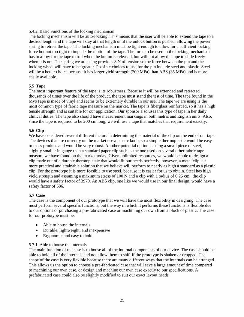
25
5.4.2 Basic Functions of the locking mechanism The locking mechanism will be auto-locking. This means that the user will be able to extend the tape to a desired length and the tape will stay at that length until the unlock button is pushed, allowing the power spring to retract the tape. The locking mechanism must be tight enough to allow for a sufficient locking force but not too tight to impede the motion of the tape. The force to be used in the locking mechanism has to allow for the tape to roll when the button is released, but will not allow the tape to slide freely when it is not. The spring we are using provides 8 N of tension so the force between the pin and the locking wheel will have to be greater. Possible choices to use for the pin include steel and plastic. Steel will be a better choice because it has larger yield strength (200 MPa) than ABS (35 MPa) and is more easily available.
5.5 Tape The most important feature of the tape is its robustness. Because it will be extended and retracted thousands of times over the life of the product, the tape must stand the test of time. The tape found in the MyoTape is made of vinyl and seems to be extremely durable in our use. The tape we are using is the most common type of fabric tape measure on the market. The tape is fiberglass reinforced, so it has a high tensile strength and is suitable for our application. Our sponsor also uses this type of tape in her daily clinical duties. The tape also should have measurement markings in both metric and English units. Also, since the tape is required to be 200 cm long, we will use a tape that matches that requirement exactly.
5.6 Clip We have considered several different factors in determining the material of the clip on the end of our tape. The devices that are currently on the market use a plastic knob, so a simple thermoplastic would be easy to mass produce and would be very robust. Another potential option is using a small piece of steel, slightly smaller in gauge than a standard paper clip such as the one used on several other fabric tape measure we have found on the market today. Given unlimited resources, we would be able to design a clip made out of a durable thermoplastic that would fit our needs perfectly; however, a metal clip is a more practical and attainable solution that we believe will perform to nearly as high a standard as a plastic clip. For the prototype it is more feasible to use steel, because it is easier for us to obtain. Steel has high yield strength and assuming a maximum stress of 100 N and a clip with a radius of 0.25 cm , the clip would have a safety factor of 3970. An ABS clip, one like we would use in our final design, would have a safety factor of 686.
5.7 Case The case is the component of our prototype that we will have the most flexibility in designing. The case must perform several specific functions, but the way in which it performs these functions is flexible due to our options of purchasing a pre-fabricated case or machining our own from a block of plastic. The case for our prototype must be:
• Able to house the internals • Durable, lightweight, and inexpensive • Ergonomic and easy to hold
5.7.1 Able to house the internals The main function of the case is to house all of the internal components of our device. The case should be able to hold all of the internals and not allow them to shift if the prototype is shaken or dropped. The shape of the case is very flexible because there are many different ways that the internals can be arranged. This allows us the option to choose a pre-fabricated case that will save a large amount of time compared to machining our own case, or design and machine our own case exactly to our specifications. A prefabricated case could also be slightly modified to suit our exact layout needs.

26
5.7.2 Durable, lightweight, and inexpensive Our case needs to be durable so that if it is bumped or dropped it will not be damaged or break. It needs to be lightweight so that it is not a burden for the user to carry around with them and so that people who do not have a large amount of strength are easily able to maneuver the case around the object that they are measuring. The case must also be inexpensive so that we can keep the cost of our device as low as possible. In order to choose a material that will meet these criteria, we performed a material search using CES EduPack 2010. Because our case must be made of plastic due to customer requirements, we searched for data sheets of plastics that were used for cases that house electronics to create a range of acceptable values for the yield strength, tensile strength, flexural modulus, density, and price for our material options. This search returned a list of 10 material choices which we will consider and decide on a case. The availability of each material will also be a very important aspect to consider in what case we will use. See appendix H for full selection criteria and material choices.
5.7.3 Ergonomic and easy to hold Our case must be shaped so that it is ergonomic and easy for the user to hold and maneuver. The size of the case is a function of what is housed inside it. Because clinicians and patients will use our prototype frequently, we want it to be as easy to use as possible. In order to create an ergonomic and easy to hold shape for our case, we will either purchase a prefabricated case, or design a case based off of the shape of a current case on the market (such as an iPod, cell phone, or tape measure) that we feel is ergonomic and easy to hold.
5.8 CES and SimaPro When selecting materials for our product, we consulted software packages CES Edupack2010 and SimaPro 7.2 for information on what materials would best suit our needs. We used CES to determine what materials would meet the specifications needed for our product to function properly and to continue working without failure. We used this software to input the specifications we needed in our material such as, density, price, yield strength, and tensile strength and CES returned possible material choices for us to use that met these specifications. We also used CES when performing a mass manufacturing process selection to help determine what processes could be used to make some of our components. We used inputs such as economic batch size, component weight and size, shape of component, and primary processes required. CES returned processes that would be able to meet all of the needs for our components and helped us to choose a viable option if mass production is needed.
After selecting the materials for our components, we used SimaPro to determine the environmental impact of our product. We chose the materials that we used for our components in SimaPro and included that mass of that material that was used. SimaPro then calculated the amount of impact that these materials has on the environment and provided bar graphs that shows this information in an easy to read fashion.
In depth information on material selection process, environmental impact, and manufacturing process selection using CES and SimaPro can be found in appendix N.
6. FINAL DESIGN Since our prototype will not be able to satisfy some of our customer requirements, we have planned out a final design which we could manufacture if we were to work on this project for longer than one semester. The most important customer requirement which we will not be able to fulfill with our prototype is the size requirement. Our original engineering specification called for the case to be approximately 12cm x 10 cm x 5 cm and weigh less than a half a pound. Our prototype is going to be enclosed in a prefabricated case which has outside dimensions of 17.2 cm x 12.12 cm x 6.35 cm. To miniaturize our prototype, we will have to minimize the size of our microprocessor and screen. See figure 18 below for a CAD image comparison of our prototype and final designs.

27
Figure 18: Size comparison of prototype and final design
The Arduino will work very well for our prototype but it is much too large for our final design. The Arduino is designed to be able to handle more components than we are using in our circuit. To cut down on size, we would have to design our own microprocessor board which would contain only the components we actually need for our design. We estimate that a microprocessor designed especially for our design would save 11.04 cm2 in surface area and if we got rid of the spacers under the board, we would save 60 cm3 in volume.
Another place where we could save room is in the LCD screen selection. We chose a screen with a backpack for the convenience of not having to write code for the text output on the screen since the backpack would process those commands for us. The backpack is large and getting rid of it would save us a lot of space. In addition, the screens without backpacks were smaller than the backpack enabled screens so we would be able to use a smaller screen as well. The smaller screen that we found [8] which would work for our final design would save us 12.4 cm2 surface area.
Figure 19: Stacking of internal components in final design
Since we would be cutting down on the size of the internal components, we would be able to use a smaller case, either prefabricated or fabricated by us. In figure 18 above, the final design is enclosed in a case with outside dimensions of 12cm x 7cm x 3.5 cm. The case still has the built in 9V battery compartment but uses space more effectively by stacking components (see figure 19 above).
7. PROTOTYPE DESIGN DESCRIPTION We have designed a prototype that we will manufacture by the Michigan Engineering Design Expo on December 9. We are using a prefabricated board and case that sacrifices size and weight because designing our own microprocessor and board goes beyond the scope of this class. The description of each component we will use and a picture of a CAD model we have created can be found in the following section.
7.1 Microprocessor [12] We have chosen to use the Arduino Duemilanove microprocessor in our device. We feel that this is the microprocessor that best performs the functions required of the microprocessor in our tape measure. We
Prototype
Final Design

28
will program this microprocessor with an algorithm that will convert the digital data received by from the optical encoder and output it to an LCD screen.
7.1.1 Basic Functions The Arduino Duemilanove performs all three of the basic functions which are necessary for our device. It can provide 5 V and 40 mA of current to power the optical encoder. The supply voltage to power the optical encoder is 5 V and the required supply current is 17 mA; therefore, the microprocessor will be able to power the encoder without an external driver. The microprocessor will also perform the function of processing the data from the optical encoder. The optical encoder outputs either high voltage or low voltage as the wheel spins, creating a pulse of high and low voltage denoting a count. These counts are inputted to the microprocessor, which uses an algorithm that we will write to calculate the amount of tape that has been extended from the case of the tape measure. Finally, our microprocessor must be able to output the calculated measurement data to an LCD screen. Using the Arduino’s digital output pins, we will send the data to an LCD screen, which will display the measurement in an easy to read manner.
7.1.2 Additional Considerations In addition to the three basic functions that our microprocessor must perform, we also considered the physical size of the microprocessor, how much heat it will generate, and how much it will cost. The dimensions of the Arduino Duemilanove are 5 cm x 7 cm which will fit well in most cases. The Arduino itself is approximately 1cm thick and will be attached to three spacers that are also approximately 1 cm thick, bringing the total height for the board to 2 cm. This height will also fit well in most cases. We discussed the issue of heat dissipation with Dan Johnson, who has a large amount of experience working with Arduino microprocessors. He explained that heat generation would be negligible due to the small amount of current (40 mA) that the Duemilanove will be supplying. Because of his previous experience using Arduino microprocessors, we conclude that this analysis is sufficient. The final consideration for the microprocessor is the price. The Arduino Duemilanove is being provided to us by Dr. Albert Shih free of charge, but purchasing one would only cost $25.00. There is also a 20% discount if you purchase more than 100 units, bringing the price down to $20.00 per unit if purchased in large quantities.
7.2 Encoder [13] We have chosen to use the Avago Technologies HEDS-5605#A06 encoder for our project because we believe it offers features that precisely meet our sponsor’s needs.
• Physical size o Vertical height – the encoder is only 18.3 mm tall, which gives us a cushion of 40.1 mm
on the top side of the case. o Footprint – the encoder is 52.1 mm wide at the widest part and 41.1 mm deep, which is
smaller than the tape spool. • Geometry
o Inner race – 15 mm, which is half a centimeter larger than the MyoTape spindle. o Attachment wings – the encoder has two wings, as seen below, that will allow us to easily
attach the encoder to our case. • Counts per revolution
o 500 counts per revolution – this gives a resolution of 0.0377 cm, which is less than 0.05 cm.
o Encoders with higher counts per revolution are available, but they all use too much current for our application.
• Compatibility with microprocessor o Channels – 2, plus 1 for increment and 2 pins for power; uses 5 digital I/O pins o Current – 17 mA, which is less than the maximum of 40 mA.

29
• Price o Single encoder – $51.04 plus shipping from digikey.com o Multiple encoders – price goes down as you order larger supplies of the component;
orders of 5,000 encoders cost $30.62 per unit.
7.3 LCD Display [14] We have chosen to use a serial enabled 16x2 5V Yellow on Blue LCD screen, which was recommended to us via email by Sparkfun Tech Support, to output the measurement to the user. This display has all of the necessary specifications and features for our device. First, this LCD screen is easy to program using the microprocessor we have chosen due to its serial backpack. This allows for easy installation because only three wires are required. This screen is also programmed using standard ASCII characters which allows for easier programming. The format of the screen fits our needs as well. The display can shown a maximum of two rows with 16 characters each. Our device only requires one row showing a maximum of five digits along with a decimal point and two letters (for example 107.65 cm). To satisfy readability, this screen has a blue backlight and outputs the text in a yellow font. We also need the screen to run on a low supply current (less than 40 mA) so that it can be powered by the microprocessor or we will have to use a DC to DC converter to power it [15]. We were unable to find an LCD screen with a backlight that could meet this current specification so we will need to use a DC to DC converter to provide the necessary 57 mA of current to the screen. This screen satisfies the I/O pin requirements for our device because it uses only three pins to attach to the microprocessor. Combining this with the 5 pins required for the optical encoder totals eight pins used, which is less than the possible 14 pins on the microprocessor. Finally, this screen can be purchased from Sparkfun for $24.95 per unit for small quantities, or for $19.96 per unit if you purchase more than 100.
7.4 Spool and Locking Mechanism [6] Figure 20: Cross sectional view of spool and locking mechanism assembly
The spool and the locking mechanism are the main mechanical components of our design and they must work together to wind and unwind the tape and translate the spinning of the spool to the encoder so that the Arduino can calculate the tape extension. In our design, we are using two MyoTape wheels to make the spool and locking mechanism combination. The main wheel holds the tape, winds the power spring, and is connected to the encoder. The second wheel will be used as the locking mechanism. We needed to break up the mechanism into two wheels because of the encoder. The encoder requires a moving shaft which will turn with the spool. The locking mechanism needs a fixed shaft so that the locking button can
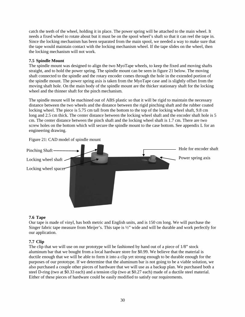
30
catch the teeth of the wheel, holding it in place. The power spring will be attached to the main wheel. It needs a fixed wheel to rotate about but it must be on the spool wheel’s shaft so that it can reel the tape in. Since the locking mechanism has been separated from the main spool, we needed a way to make sure that the tape would maintain contact with the locking mechanism wheel. If the tape slides on the wheel, then the locking mechanism will not work.
7.5 Spindle Mount The spindle mount was designed to align the two MyoTape wheels, to keep the fixed and moving shafts straight, and to hold the power spring. The spindle mount can be seen in figure 21 below. The moving shaft connected to the spindle and the rotary encoder comes through the hole in the extended portion of the spindle mount. The power spring axis is taken from the MyoTape case and is slightly offset from the moving shaft hole. On the main body of the spindle mount are the thicker stationary shaft for the locking wheel and the thinner shaft for the pinch mechanism.
The spindle mount will be machined out of ABS plastic so that it will be rigid to maintain the necessary distance between the two wheels and the distance between the rigid pinching shaft and the rubber coated locking wheel. The piece is 5.75 cm tall from the bottom to the top of the locking wheel shaft, 9.8 cm long and 2.5 cm thick. The center distance between the locking wheel shaft and the encoder shaft hole is 5 cm. The center distance between the pinch shaft and the locking wheel shaft is 1.7 cm. There are two screw holes on the bottom which will secure the spindle mount to the case bottom. See appendix L for an engineering drawing.
Figure 21: CAD model of spindle mount
7.6 Tape Our tape is made of vinyl, has both metric and English units, and is 150 cm long. We will purchase the Singer fabric tape measure from Meijer’s. This tape is ½” wide and will be durable and work perfectly for our application.
7.7 Clip The clip that we will use on our prototype will be fashioned by hand out of a piece of 1/8” stock aluminum bar that we bought from a local hardware store for $0.99. We believe that the material is ductile enough that we will be able to form it into a clip yet strong enough to be durable enough for the purposes of our prototype. If we determine that the aluminum bar is not going to be a viable solution, we also purchased a couple other pieces of hardware that we will use as a backup plan. We purchased both a steel D-ring (two at $0.33 each) and a tension clip (two at $0.27 each) made of a ductile steel material. Either of these pieces of hardware could be easily modified to satisfy our requirements.
Pinching Shaft
Locking wheel shaft
Locking wheel spacer
Hole for encoder shaft
Power spring axis

31
7.8 Case [16] We have chosen to purchase a pre-fabricated SERPAC S-Series 273 case to use for our prototype because we feel that it will best meet the requirements we have set for the case, and will also save us time in the manufacturing stages of our prototype.
7.8.1 House the internals The case that we have chosen is specifically made to house electronic components so it will be a good fit for our needs. The case comes with a 9 V battery enclosure with leads that will hold our battery and be the starting point for our electrical circuit. The case is also machinable so we will be able to make some modifications to it in order to allow for the best possible internal configuration.
7.8.2 Durable, lightweight, and inexpensive The SERPAC case that we have chosen is made from high impact ABS plastic, which was one of the materials returned from our CES search. This material is very durable and has a tensile strength of 4500 psi [17], which, using the area of the smallest face on the case and the equation of stress equals force divided by area, means that a force of almost 54900 lbs would be required to break the case. This force is much larger than any for that our case would encounter in its use, so this material is durable enough to use. The pre-fabricated case that we have decided to purchase weighs approximately 0.49 lbs so it meets the requirement of being lightweight. Finally the case costs only $12.28 which satisfies our need for an inexpensive case because this price is well within our budget.
7.8.3 Ergonomic and easy to hold The SERPAC S-Series 273-B pre-fabricated case that we have chosen has an ergonomic, easy to hold shape. This case is rectangular with rounded edges which make it easy to hold. The rounded edges also remove the possibility of any sharp corners that could accidentally scratch or poke the user or patient which is important because patient comfort and safety is very important. The only downside to this case is that it is rather large and bulky. It has dimensions of 6.88” x 4.88” x 2.51” (approximately 17.5 x 12.4 x 6.4 cm) which is larger than our specification of 12 x 10 x 5 cm by a fair amount. We have determined that this is acceptable for our prototype due to the fact that our microprocessor board is rather large. This issue of size is rectified in our final design where we can use a smaller case due to our smaller, custom designed microprocessor board. Even with the issue of the size being slightly larger than planned, we still expect that this case will be ergonomic and easy for the user to hold and maneuver.
8. FABRICATION PLAN This section provides an overview of all fabrication and manufacturing processes including machining and assembly. Also, a section is included for wiring the electrical components. A detailed description of all the raw materials and components that we have purchased for our prototype can be found in appendix K. Note, that this section is subdivided into two parts, one from mechanical processes and one for electrical. It is advised that the electrical processes be completed first before assembling everything in the case.
8.1 Designsafe Analysis Designsafe was used to assess the risks and hazards associated with the fabrication of our prototype. We analyzed the fabrication of the spindle holder, the changes we will make to the case, and the actual assembly of the prototype.
The spindle holder is potentially dangerous because we are cutting the piece out of a block of ABS. The operator must be careful around the spinning cutting tool of the mill. The risk can be decreased through proper techniques, careful use, supervision, and safety glasses.
We have purchased a prefabricated case and will be making modifications to it to fit our design. We will need to cut screw holes in the bottom to attach the internal components, a hole in the top for the locking

32
button, and slots for the tape and the LCD screen. We will be using a drill press to cut the holes in the top and bottom and the mille to cut the slots in the top. This is dangerous because of the inherent risks of using heavy machinery. We can decrease the possibility of injury by using standard procedures, by being careful, and by wearing safety glasses.
Finally, the final assembly of the prototype could be dangerous for our team. Wiring the components together could be dangerous since we do not have a lot of experience wiring electrical components. There is a possibility that we wire the circuit incorrectly which could result in component failure. This is dangerous since we could get shocked or burned if the current is too high through one of the components. We can reduce the possibility of injury by reading all of the instruction manuals of our components, by having professional supervision, by using standard procedures, and by being careful. There is also a risk of pinching a finger in our power spring. The power spring is the main mechanical component in our design and it is used to draw the tape back into the case. There is a chance that somebody could get their finger caught in the tape of the spring. We can reduce the possibility of injury by taking turns working with the prototype, supervising each other, and reading instruction manuals.
8.2 Machining Processes The two parts that need to be machined are the spindle mount and the plastic enclosure. We do not have to fabricate the plastic enclosure from scratch; it only needs to be modified.
8.2.1 Spindle Mount The spindle mount is to be machined out of a block of ABS plastic with initial dimensions of 1” x 6” x 6”. Its purpose is to provide a mount and stability for the locking wheel and the tape wheel. The spindle mount will not require great precision, so we will be able to machine it in the University of Michigan machine shop. The fabrication process is listed below in table 3.
Table 3: Machining processes for spindle mount Operation Material Tool Feed Speed Cut to size ABS Band saw n/a 300 fpm Face mill ABS Face mill 2-3 in/min 1000-1500 rpm Drill holes ABS 1/4” drill bit 2-3 in/min 1000-1500 rpm Drill holes ABS 1/8” drill bit 2-3 in/min 1000-1500 rpm
The spindle mount needs one through hole, which will align with the shaft from the optical encoder, and a hole for a dowel pin to be pressed into. The dowel pin will be used to apply a force to the tape to keep it from automatically retracting. The spindle will also have two holes drilled in the bottom that will be used to secure it in place.
8.2.2 Plastic Enclosure The plastic enclosure comes pre-fabricated but it not ready to be used in our prototype. Both the top and bottom parts of the case need to be modified. We first have to cut away some of the material from the inside of the top case, then we have to drill a hole and make a few cuts (for before and after images see figure 22, a through d). The bottom of the case needs holes drilled through it to allow for screws to pass through. Fabrication of the plastic enclosure requires more precision than the spindle mount but can still be done on a mill. The holes and cutouts on the case must align with the components they are met for so the case will fit together properly. The fabrication process is listed below in table 4.
Table 4: Machining processes for plastic enclosure Operation Material Tool Feed Speed Remove Material ABS face mill 2-3 in/min 1000-1500 rpm Drill Hole ABS 3/8” drill bit 2-3 in/min 1000-1500 rpm Cut slots ABS 1/4” router 2-3 in/min 1000-1500 rpm
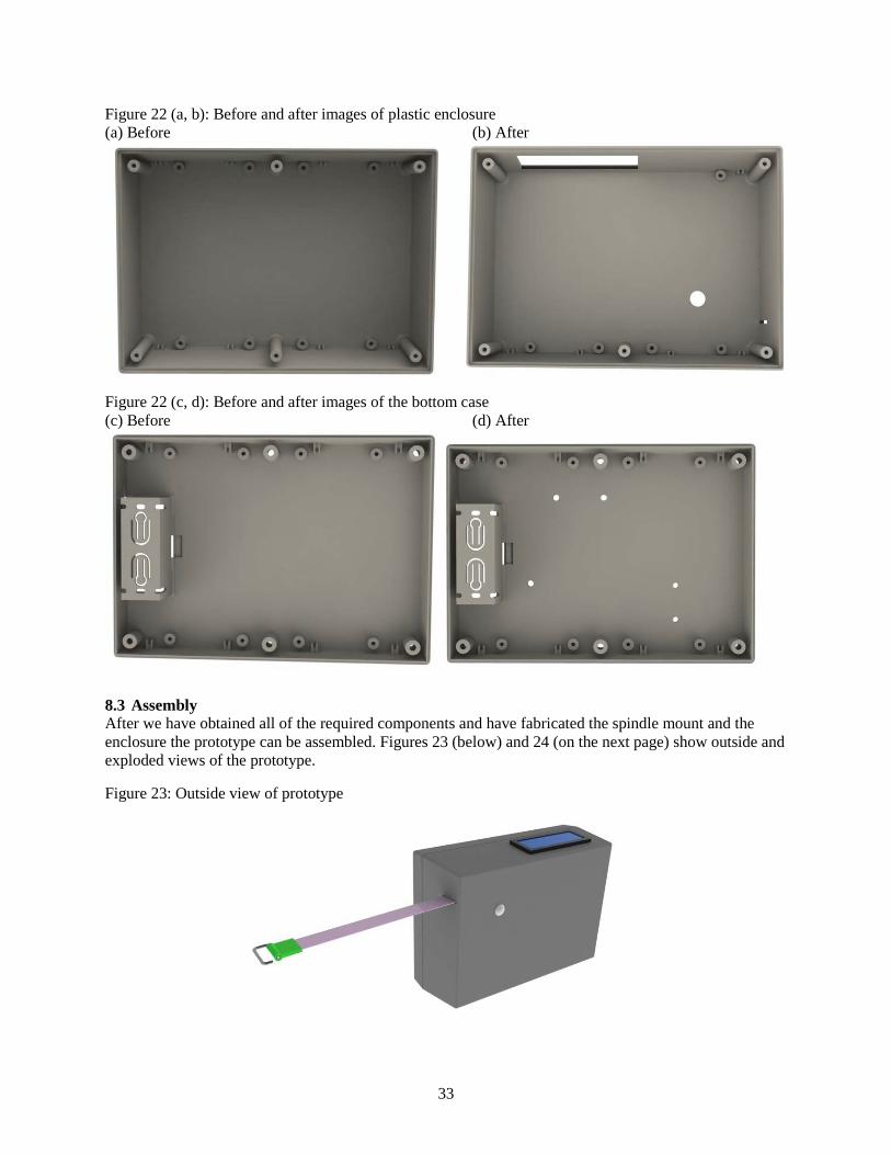
33
Figure 22 (a, b): Before and after images of plastic enclosure (a) Before (b) After
Figure 22 (c, d): Before and after images of the bottom case (c) Before (d) After
8.3 Assembly After we have obtained all of the required components and have fabricated the spindle mount and the enclosure the prototype can be assembled. Figures 23 (below) and 24 (on the next page) show outside and exploded views of the prototype.
Figure 23: Outside view of prototype

34
Figure 24: Exploded view of prototype
8.3.1 Install Arduino board The Arduino board will be held in place by six screws and three spacers. Three holes were drilled in the plastic enclosure to provide space for the attachment screws to go through. The first step to install the Arduino board is to pass three screws through the bottom of the case and secure down the spacers that provide clearance between the Arduino board and the enclosure. Next, the Arduino board can be placed on top of the spacers then secured into place by screwing in the final three screws (see figure 25 below). The Arduino board is placed close to the battery location, so the battery connector should be installed next by attaching wires from the battery output to the voltage input on the Arduino board. Also, the DC to DC converter needs to be installed in the case. This is done by gluing the converter board to a piece of ABS then gluing this piece down to the bottom of the case, in between the Arduino board and the battery holder.
Figure 25: Arduino board installation

35
8.3.2 Install Optical Encoder After the Arduino board is installed the optical encoder can be secured in place. The encoder requires two screws, which will pass through the bottom of the case and screw into the wings on the optical encoders (see figure 26). Once the encoder is secured in place the ground and voltage input can be connected to the Arduino board. Next the output channels on the encoder can be connected to the digital input pins on the board.
Figure 26: Optical encoder installation
8.3.3 Spindle Mount Assembly and Installation Before the spindle mount can be installed it first has to be completed. Two shafts from the MyoTape need to be attached to the top face of the spindle mount using glue. The shafts serve the purpose of holding the power spring and locking wheel in place. Also, a dowel pin must be press fit into the hole next to the locking wheel. The dowel pin will be used to apply a contact force to the tape and locking wheel to keep it from automatically retracting.
After the Arduino board and optical encoder have been secured in place and the spindle mount assembly is completed, the spindle mount can be installed. The spindle mount is attached to the enclosure by two screws that pass through the bottom of the case that screw directly into the spindle mount (see figure 27 below). When installing the spindle mount it is important to align the shaft from the optical encoder with the hole that is on the spindle mount.
Figure 27: Spindle mount and assembly installation
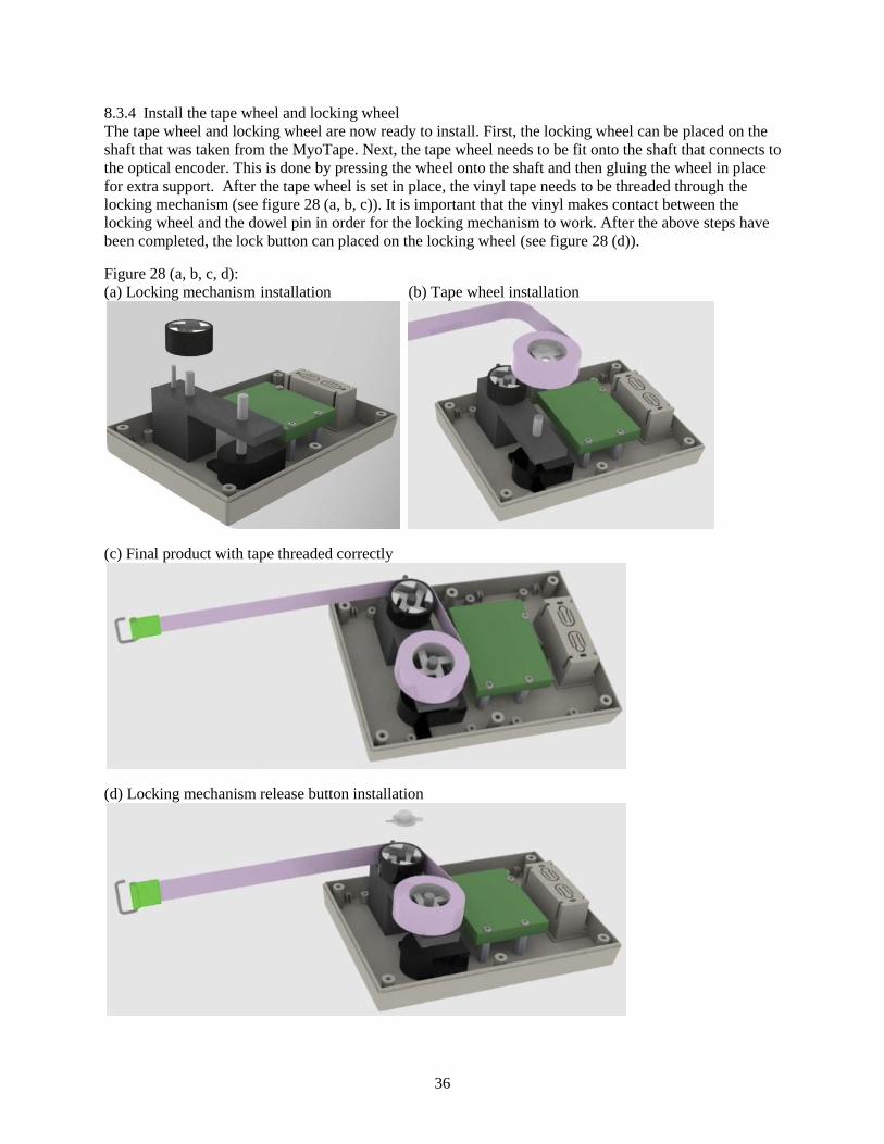
36
8.3.4 Install the tape wheel and locking wheel The tape wheel and locking wheel are now ready to install. First, the locking wheel can be placed on the shaft that was taken from the MyoTape. Next, the tape wheel needs to be fit onto the shaft that connects to the optical encoder. This is done by pressing the wheel onto the shaft and then gluing the wheel in place for extra support. After the tape wheel is set in place, the vinyl tape needs to be threaded through the locking mechanism (see figure 28 (a, b, c)). It is important that the vinyl makes contact between the locking wheel and the dowel pin in order for the locking mechanism to work. After the above steps have been completed, the lock button can placed on the locking wheel (see figure 28 (d)).
Figure 28 (a, b, c, d): (a) Locking mechanism installation (b) Tape wheel installation
(c) Final product with tape threaded correctly
(d) Locking mechanism release button installation

37
8.3.5 Install LCD and Switch Before the LCD can be installed into the side of the case, it first has to be wired to the Arduino board, and to the DC to DC converter. The LCD can be press fit into the hole that has been cut for it. The DC to DC converter is required because the LCD needs more current than the Arduino can supply. After the converter is in place it can be wired into the Arduino board. The switch can also be place in the slot that is cut out for it.
Figure 29: LCD Installation
Figure 30: Switch Installation
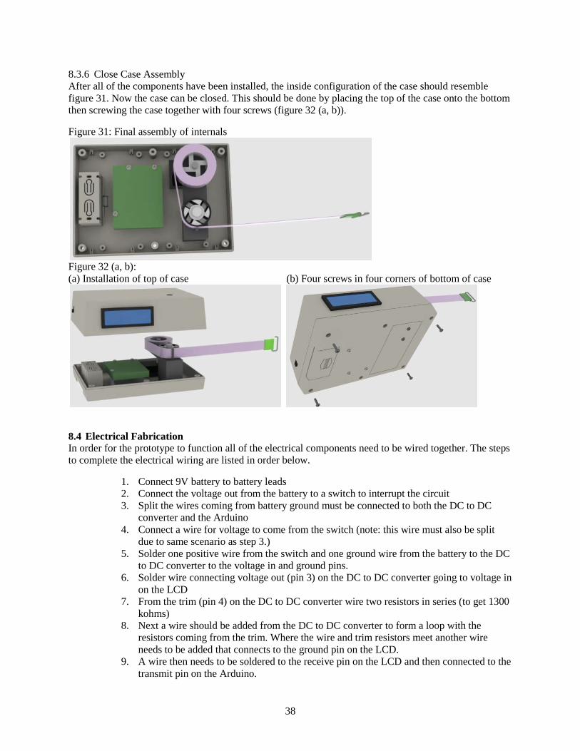
38
8.3.6 Close Case Assembly After all of the components have been installed, the inside configuration of the case should resemble figure 31. Now the case can be closed. This should be done by placing the top of the case onto the bottom then screwing the case together with four screws (figure 32 (a, b)).
Figure 31: Final assembly of internals
Figure 32 (a, b): (a) Installation of top of case (b) Four screws in four corners of bottom of case
8.4 Electrical Fabrication In order for the prototype to function all of the electrical components need to be wired together. The steps to complete the electrical wiring are listed in order below.
1. Connect 9V battery to battery leads 2. Connect the voltage out from the battery to a switch to interrupt the circuit 3. Split the wires coming from battery ground must be connected to both the DC to DC
converter and the Arduino 4. Connect a wire for voltage to come from the switch (note: this wire must also be split
due to same scenario as step 3.) 5. Solder one positive wire from the switch and one ground wire from the battery to the DC
to DC converter to the voltage in and ground pins. 6. Solder wire connecting voltage out (pin 3) on the DC to DC converter going to voltage in
on the LCD 7. From the trim (pin 4) on the DC to DC converter wire two resistors in series (to get 1300
kohms) 8. Next a wire should be added from the DC to DC converter to form a loop with the
resistors coming from the trim. Where the wire and trim resistors meet another wire needs to be added that connects to the ground pin on the LCD.
9. A wire then needs to be soldered to the receive pin on the LCD and then connected to the transmit pin on the Arduino.

39
10. The optical encoder can now be connected to the Arduino by using jumper wires. The wires connect to their respective pins shown in figure 33 below.
11. The voltage and ground from the battery can be connected to the Arduino 12. The switch can now be turned on to power the device
After these steps are complete all of the electrical components should be working together. The Arduino had to be programmed to take an input from the encoder and translate into a distance. The code used in our device can be found in appendix O.
Figure 33: Schematic of electrical circuit, including Arduino, LCD, DC/DC converter, and optical encoder
9. VALIDATION RESULTS After completing the manufacturing and assembly of our prototype, we performed several experiments in order to prove that our engineering specifications have been met. This section discusses the results of our tests, listed in table 5 below, in detail.
Table 5: Customer requirements and engineering specifications to be validated Requirement Specification Accurate Measurements Must measure known circumference of an object within ½ mm Repeatable Measurements Must provide repeatable, reproducible results as required by GR&R
study Length Tape length must exceed 200 cm Ease of Use User should be proficient within 1 minute of training Easily Cleaned Must be able to be cleaned with an alcohol pad in less than 30 seconds

40
Robustness Must withstand 5 drops from 1 m and still function Locking Mechanism Must withstand a force of 8 N and not retract unless release button is
pressed
9.1 Accurate Measurements One of the most important customer requirements was to make a device that is accurate. In order to make our device accurate, we calibrated it by measuring known distances (ranging from 0 to 60 cm due to device limitations) multiple times. The tape was extended to lengths in increments of 5cm. Each time the tape was extended, the count from the encoder was recorded, and the tape was returned to the starting position. After the tape was returned to the starting position, the device was power cycled to ensure that the count started from zero for each measurement. The tape was extended to each distance three times so the error in the device could be calculated. After calibrating the device we determined that the error in measurements (on a 95% confidence interval) ranged from 0.02 cm to 0.09 cm. The largest error occurred at 30cm and mostly stemmed from the precision error in the encoder. Other error taken into account included, human error in pulling out the tape, resolution error in the tape (resolution of 0.1 cm), and error caused by noise due to the voltage input. Figure 34: Calibration curve for measurement device
9.2 Gauge Repeatability and Reproducibility Testing We performed gauge repeatability and reproducibility (GR&R) testing on the MyoTape, the standard tape measure, and our prototype. GR&R is used to “measure the capability of a gauge…to obtain the same measurement reading every time the measurement process is undertaken for the same characteristic or parameter.” [11] Repeatability refers to the ability of the device to produce the same measurement when measured multiple times by the same person and is typically seen as a measure of user error. Reproducibility is the ability of the device to produce the same measurement across different users.
9.2.1 Procedure We used five objects of various shapes and sizes: an empty soda can, a trash can, a sieve, a can of motor oil, and Kyle Schilling’s forearm at a specified point. Each of the objects we measured were round since the devices we purchased were created specifically for measuring body parts. We measured 4 different objects with the prototype: a Gatorade bottle, a metal post, a 2-liter soda bottle, and a bottle of orange
y = -5E-07x2 + 0.0258x + 1.3069R² = 1
0
10
20
30
40
50
60
0 500 1000 1500 2000 2500
Leng
th (c
m)
Counts

41
juice. We had each team member measure each object three times with each measuring device. We then compiled the results in an Excel file and performed calculations to find the repeatability and reproducibility of both the MyoTape, the standard, fabric tape measure, and the prototype.
9.2.2 Results Using the numbers obtained, we compiled the averages and standard deviations of the measurements taken by each team member in table 6. From these numbers, we were able to calculate numbers for repeatability and reproducibility, and the percentage of tolerance that each provided. Repeatability was calculated by multiplying the average of the average range for each sample and each appraiser by a constant dependent on the number of trials each sample was measured. Reproducibility was calculated by multiplying the range of the average measurement for each appraiser by a constant dependent on the number of appraisers. The range and reproducibility combined number is the square root of the sum of the squares of the reproducibility and repeatability numbers. Each of the percentages is simply what percentage of the total tolerance is due to reproducibility and repeatability. The percentage values are listed below in table 7.
Table 6: Results of the gauge repeatability and reproducibility study (all numbers are in cm)
Arnold Palmer Can
Kyle's Forearm Trash Can Sieve
Motor Oil Can
Myotape AVG 23.392 30.033 123.625 64.333 30.083 STDEV 0.227 0.368 0.154 0.115 0.180
Standard Cloth
AVG 23.208 30.275 123.292 64.567 30.142 STDEV 0.067 0.218 0.151 0.065 0.090
Gatorade Bottle Metal Post 2-Liter Bottle
Orange Juice
Prototype AVG 23.412 18.820 34.468 19.778 STDEV 0.196 0.115 0.205 0.215
From these calculations, we can see that the standard cloth tape is more repeatable and reproducible than the MyoTape; however, neither tape is even close to being in an acceptable range for the given tolerance level. The very good range for percentage of tolerance is between 0 and 10 percent; anything between 10 and 30 percent is acceptable; above 30 percent is bad. Unfortunately, both these measuring devices are in the very bad range at 78.41% error for the MyoTape and 59.58% error for the fabric tape. These are very poor results, likely due to the fact that the tape has too large a resolution to accurately measure to the nearest millimeter. If the resolution is not at least one tenth of the tolerance, you are not likely to get acceptable results. In this case, our resolution is the same as our tolerance, leading to the poor R&R numbers presented below. Our design will have a smaller resolution, leading to more acceptable GR&R results.
From the numbers in table 7 on the next page, it can be seen that our prototype does not in fact perform better in overall repeatability and reproducibility than either the MyoTape or the cloth measuring tape. Repeatability is 79.02%, which is much higher than either the MyoTape or the cloth measuring tape. Reproducibility, the ability of a gauge to produce consistent measurements regardless of the user, is only 12.27%, which is much lower than the MyoTape and about 5% lower than the cloth tape. We are excited that the reproducibility is within the acceptable range because it means that our design does indeed increase the consistency of measurements from person to person (or clinician to clinician). Unfortunately, we have very poor repeatability numbers, which means that each person did not have consistent measurements within their 3 trials. We believe this error is due to the inconsistent cinching of the loop around the four objects we measured. The torsion spring that we are using is not powerful enough to cinch the loop consistently. Because the spring is not powerful enough, we have redesigned our final

42
product to incorporate a stronger spring, which would lead to a more consistent cinching force and more consistent measurements.
An additional source of error is the device’s inability to accurately measure how much tape has retracted. The device was extremely accurate when the tape was being extended; however, when we fully retracted the tape, the outputted measurement was always at least a centimeter larger than when the device was originally turned on. We believe that this phenomenon is due to a couple of issues. First, because the retracting spring is weak, the tape does not wind up on the spool exactly the same way every time. Another factor is the screen usually refreshes as the tape is being retracted, which causes the microprocessor to hold up and miss counts. This issue affects the GR&R numbers because the tape must be extended to a distance larger than the object, then retracted till it is snug around the object, which could cause an error. We are confident that this issue will be corrected when the Arduino microprocessor is replaced with a custom designed model and the electronic bugs are worked out.
For the full GR&R numbers and calculations, please see appendix C.
Table 7: Gauge repeatability and reproducibility study values
MyoTape Standard Cloth Prototype % Repeatabillity 28.50% 42.51% 73.02% % Reproducibility 49.91% 17.07% 12.27% % Reproducibility and repeatability 78.41% 59.58% 85.29%
9.3 Length The length of the tape in our prototype is 60 inches, or approximately 150 cm; however, because of the limited space the torsion spring has to spool up, the tape can only be extended about 80 cm. If the tape is extended more than this, the spring binds up and the tape will not retract back into the case. Currently, our prototype does not meet the specification. Because of the design flaw in our prototype, we have changed our final design to leave more space for the torsion spring to load without binding. We believe that our final design will be able to meet the 200 cm specification with ease.
9.4 Ease of Use We allowed many people to handle our prototype device at the design expo on the 9th of December. Everyone who used our device was able to immediately see how it functioned with ease. The only point that most everyone missed is that the device needs to be turned on before the tape is extended. We hope to correct this in the final design by not using an on/off switch at all; instead, the device will simply turn on when the tape is extended and will turn off after a minute of inactivity. Since the rest of the device was deemed self-explanatory, we believe that our final design will easily meet our ease of use specification.
9.5 Easily Cleaned Geeta Peethambaran cleans the tape between patients by simply folding an alcohol pad over the tape and running it the full length of the tape to disinfect it and prevent the spread of disease and infection. To validate our specification, we had each group member clean the tape 5 times with an alcohol pad, a total of 20 times. All group members agreed that this was no harder than with the tape measures Ms. Peethambaran already uses. Additionally, we checked the tape for signs of wear and fading or smearing of the measurements and could find no ill-effects. Since the tape material will be the same for our final design, we have validated that the tape of our device is easily cleaned.
9.6 Robustness Because it is possible for our device to be dropped in the course of its use, we determined a specification for robustness that the device must withstand five drops from one meter off the ground and still function. Unfortunately, we were not able to test this because we are quiet certain that the prototype would not

43
survive even one drop from 1 meter without sustaining damage that would permanently affect the performance of the device. Normally, we would not mind that the device is broken once we have completed all testing, but we hope to send our prototype to Taiwan with Professor YY Tsai to see if any company there is interested in mass producing our final design. He will need the prototype to show proof of concept to these companies and hopefully get them to invest in the project.
While we did not do any testing on the device, our main concern is that the intricate moving parts in our prototype would be jostled and broken because they are not made specifically for our implementation. If we were able to fully design parts that fit perfectly into the case with little extra room, then we would be much more confident that our ABS case would hold up to the drop test for robustness. The ABS we used in our final design is high impact and having a yield strength of at least 4000 psi which is roughly 1000 times higher than any force that would be encountered from a drop of 1 meter.
9.7 Locking Mechanism The auto-locking wheel mechanism must be able to withstand the force of the power spring that is pulling to retract the tape whenever it is extended. When we performed testing on the MyoTape, which uses the same auto-locking wheels and power spring as our prototype, we estimated using a force gauge that the power spring pulls with a force of 8 N to retract the tape. We are using the same power spring and locking mechanism in the prototype as was used in the MyoTape, so theoretically, this specification should work. Unfortunately, several factors combined to prevent our locking mechanism from working as successfully as we had originally hoped. For one, the machining in our prototype is not as precise as the MyoTape, which fits together perfectly, leading the locking mechanism to work only occasionally. More importantly than the poor fit of our parts was the power spring not being strong enough. Because it is not pulling constantly or hard enough against the locking mechanism, sometimes the tape does not even retract when the button is pushed due to a lack of spring power. This will clearly be fixed when the power spring is more powerful and has more room to coil in the final design. As is, the prototype fails to meet this specification.
10. DISCUSSION After completing our prototype, we have broken down each function and determined its strengths and weaknesses. We believe that our prototype’s biggest strength was the concept of using an optical encoder, combined with a microprocessor and LCD. The encoder worked well in this configuration, but we believe it will work better and more efficiently with electrical components specifically designed for this purpose. Other strengths of the prototype were the case material, the fact that it had a slot for a battery to fit in, and the spindle mount worked well and provided enough room to increase the length of tape. The prototype also had weaknesses that can be improved upon, including: the locking mechanism, component sizes, the internal assembly, the clip mechanism, and the power spring configuration. Below we detail how each of the weaknesses above could be addressed in the future.
• Switching to a pinch locking mechanism would simplify the spindle assembly. We would design a pinching mechanism similar to the one found in the eTape which we reverse engineered in appendix F. The mechanism would be located at the slot where the tape exits the case. The user would push down on a slider or button on the outside of the case and the mechanism would pinch down on the tape, keeping it from retracting.
• Components could be stacked to allow for a smaller case size. Our concept is very large because our internal components are all attached to the bottom of the case. This is a waste of useable space. We could decrease the size of our case if we had some of the components attached to the top and some to the bottom so that they are stacked on top of each other.
• The case is very difficult to put together since the springs must be wound before they can be put in the case. There needs to be some sort of assembly inside the case which could hold the spindles flat, keeping the power spring and locking button spring from coming out of place. A simple, thin

44
bridge piece could be constructed which would fit just under the top. It could be on a hinge and could swing down on top of the spindles before the top is attached. See figure 35 below.
Figure 35: Bridge piece which would allow for easier assembly of components
• For personal use, the clip mechanism is too complicated. Measuring arms is very difficult since the same hand must be used to hold the case, push the locking button and attach the clip around the other arm. A fixed loop system, similar to the MyoTape design, would be much easier for personal measuring use.
• The power spring currently sits inside the main spindle wheel. When we added longer tape and incorporated a more complicated locking mechanism, we did not realize that the standard power spring would not be strong enough to retract tape longer than 80 cm. We could not improve the power spring because it is located inside the spindle wheel in our design. The power spring needs to be on the encoder/main spindle shaft but we could have moved it down on the shaft if we had known it would not be strong enough. What we should of done was made the spindle mount wider and then cut a hole underneath the spindle mount arm that the spring could sit in. Then we could have cut a slot in the main spindle shaft to attach it. See figure 36 below for a CAD picture of the change.
Figure 36 – Power spring improvement idea which moves the power spring from inside the main spindle wheel to a hole in the arm of the spindle mount
11. RECOMMENDATIONS There are several recommendations that our team would like to propose for the next redesign of the Accurate Measurement of Edema Swelling device.

45
• Using strong adhesive instead of screws to secure internal components to the case will make the digital tape measure’s exterior look cleaner
• The spindle mount uses a lot of excess material. Making the spindle mount thinner or hollow would reduce the overall weight of the digital tape measure and could free up space to keep some of the electrical wires bundled up.
• The part of the case right around the hole that the tape extends out of should be flat so that it is easier for the user to make accurate measurements. The slanted surface of the prototype sometimes slightly changed the amount that the tape retracted when we were performing GR&R testing.
• The power spring should be moved below the spindle mount. In its current location inside the main spindle wheel, the length of the spring is limited by the diameter of the interior of the spindle wheel. Attaching the spring to the shaft between the optical encoder and the extended part of the spindle mount would allow for a more powerful spring to be used. The length of the tape and the complexity of the locking mechanism could then be improved. A possible solution for attaching the power spring to the shaft is shown in figure 36 on the previous page.
12. CONCLUSION In conclusion, we have defined the problem presented to us by our sponsor, Geeta Peethambaran, determined engineering specifications and customer requirements for a device to solve the defined problem, and created a prototype and a final design to solve the problem. Our prototype and final design use a combination of an optical encoder and a microprocessor to determine the length of the extended tape. We performed parameter analysis on our alpha design in order to choose specific components for our prototype. We then created a fabrication and assembly plan, which we used to make our prototype. After completing our prototype and presenting at the design expo, we tested it for accuracy and repeatability by creating calibration curves and performing a gauge repeatability and reproducibility test. Finally, we have proposed a final design that will improve on our prototype design by making the device much smaller and easier to use, while still keeping the same functionality and accuracy.
13. ACKNOWLEDGEMENTS Our work on this project would not have been possible without the support of the following people. We are indebted to them for their support through this entire process:
• Geeta Peethambaran – Geeta was our primary sponsor. She met with us for multiple meetings even though she was very busy with her patients.
• Professor Albert Shih – Professor Shih was our advisor for this project. He met with us multiple times every week. He helped us find solutions for many of the problems we encountered over the course of this project.
• Dan Johnson – Dan was our graduate student instructor, he helped us extensively with selecting, purchasing, and implementing our electrical components.
• Toby Donajkowski –Toby runs the ME mechatronics lab in GG Brown. He helped us solve some of the electronics problems associated with our concept as well as helping us machine a difficult part of the spindle mount.
• Bob Coury and John Mears – Bob and John are engineering technicians that run the machine shop. They helped us with machining and fabricating our prototype.
• Kris Schilling – Kyle’s older brother, he helped Kyle solder our internal electronic components together over the Thanksgiving break.
• Professor Grant Kruger – Professor Kruger answered many of our questions about the electronics

46
REFERENCES 1. Ma'at-Ra, D. 2010. 2. Rosenbach, D., MyParonychia.jpg, Editor. 2009, Wikipedia. 3. Staff, M.C. Edema. 2010; Available from: https://www.mayoclinic.com/health/edema/DS01035. 4. Heidenreich, P., Peripheral Edema: Prevalence and association with outcome in primary care, in
VA Palo Alto Health Care System, Stanford University. 5. MABIS Tape Measure. 9/14/2010]; Available from:
http://www.amazon.com/gp/product/B001BJO22Q/ref=oss_product. 6. MyoTape Body Tape Measure. 9/14/2010]; Available from:
http://www.amazon.com/gp/product/B0017OE4MI/ref=oss_product. 7. MyoTape D Optical Digital Tape Measure. 9/14/2010]; Available from:
http://www.directsupercenter.com/detail_290005__117.html. 8. eTape Digital Measuring Tape. 9/14/2010]; Available from:
http://www.thinkgeek.com/gadgets/tools/9d77/. 9. Rackulator. 9/14/2010]; Available from: http://www.cabelas.com/link-
12/product/0022206226036a.shtml?cm. 10. Metabolism Measure Digital Measuring Tape. 9/14/2010]; Available from:
http://www.japantrendshop.com/metabolism-measure-digital-measuring-tape-p-600.html 11. Gauge Repeatability and Reproducibility. 2004 9/20/2010]; Available from:
http://www.siliconfareast.com/grr.htm. 12. Arduino. Arduino Duemilanove. 11/4/2010]; Available from:
http://www.arduino.cc/en/Main/ArduinoBoardDuemilanove. 13. DigiKey. Avago Technologies HEDS-5606#A06. 11/4/2010]; Available from:
http://search.digikey.com/scripts/DkSearch/dksus.dll?Detail&name=516-2024-ND. 14. Sparkfun. Serial Enabled 16x2 LCD - Yellow on Blue 5V. 11/4/2010]; Available from:
http://www.sparkfun.com/commerce/product_info.php?products_id=9396. 15. DC to DC converter module 6A. 10/25/2010]; Available from:
http://www.sparkfun.com/commerce/product_info.php?products_id=9275. 16. Electronics, A. Serpac S-Series 273. 11/4/2010]; Available from:
http://www.alliedelec.com/search/productdetail.aspx?SKU=8820273. 17. Corporation, C.M. Polylac PA-747. 2010 [cited 2010 November 5]; Available from:
http://catalog.ides.com/datasheet.aspx?I=22235&E=15890. 18. Gustave H. Soule, J., Electronic Read-out Tape Measure. 1975, The Raymond Lee Organization:
United States. 19. Grant, W.W., Digital Display Tape Measure with Photoelectric Sensing of Tape Displacement.
1978: United States. 20. Isamu Washizuka, I.T., Electronic Digital Tape Measure Having Flexible Measuring Tape. 1982,
Sharp Kabushiki Kaisha: United States. 21. Caldwell, W.K., Hand Held Digital Measuring Device. 1985: United States. 22. Corcoran, B.H., Digital Display Tape Measure. 1995. 23. Sanoner, H., Digital Measuring Instrument Having Flexible Measuring Line. 2005, Solar Wide
Industrial, Ltd.: United States. 24. KR Tools 10217 Pro Series Fiberglass Reel Tape Measure. 10/2/2010]; Available from:
http://www.amazon.com/gp/product/B002Q8HHG4/ref=noref?ie=UTF8&s=hi&psc=1.

47
APPENDIX A: COMPETETIVE PRODUCTS There are many different types of tape measures used for a variety of applications on the market today. Stiff, metallic tape measures are most commonly used for construction, whereas cloth or flexible tape measures are commonly used for tailoring or dressmaking. Physical therapists are currently using fabric tape measures to measure the swelling caused by edema. The problem with these tape measures is that there is no way for the physical therapist to determine if consistent tension is being applied, which causes the measurements to be less accurate. Current competitors on the market (table A.1) that could possibly be used to measure the swelling include: flexible measuring tapes [5], MyoTape [6], MyoTape D [7], digital measuring tape [8], Rackulator [9], and Metabolism Measure [10]. For larger pictures, please see appendix B.
Table A.1: Comparison of competitors on the market
Customer Requirements
Import-ance
Fabric Tape Measure
[5]
MyoTape [6]
MyoTapeD [7]
Digital Tape
Measure [8]
Rackulator [9]
Metabolism Measure
[10]
Picture
Accuracy* 5 GR&R GR&R - 0.01 mm - - Repeatability* 5 GR&R GR&R - - - - Units 5 SI, English SI, English SI, English SI, English English Metric Cost 3 $3.33 $5.28 $10.95 $24.99 $119.99 $493.00 Length 2 150 cm 150 cm infinite 16’ N/A 50-150 cm Digital Display 5 No No Yes Yes Yes Yes Resolution 1 0.5 mm 0.5 mm 0.1” 1/32" .1 inch 0.1 cm Easily cleaned 5 Marginal Marginal Yes Yes Yes Yes Constant tension 3 No Yes N/A No N/A N/A Size 4 Yes Yes Yes No No Yes Uses Batteries 2 No No Yes Yes, LR44 Yes, 2 AAA Yes, 2AAA Stores data 3 No No Yes Yes Yes Yes Plastic 2 Yes Yes Yes No No Yes Locking
2 No No N/A Yes Yes Yes
* see GR&R section on page 40 and appendix B for further breakdown
In table A.2 on the next page, we have summarized the major pros and cons of each product. As you will see, each has a major con that precludes it from being the perfect product for quantifying edema in arms, legs, and other body parts.

48
Table A.2: Pros and cons of competitors on the market Product Pros Cons Fabric tape measure
Cost, readily available, flexible tape Not possible to apply constant tension, no digital readout
Myotape Flexible tape, constant tension, locking mechanism, cost
No digital readout
MyoTapeD Digital readout Inaccurate due to user differences Digital Tape Measure
Digital readout, relatively low cost, accurate
Metallic, non-flexible tape
Rackulator Digital readout Made for deer, poor resolution, similar to MyoTapeD, expensive ($120)
Metabolism Measure
Digital readout, created specifically for measuring body parts
Smallest measurement is 50 cm, prohibitively expensive ($500)

49
APPENDIX B: COMPETIVE PRODUCTS ON THE MARKET Mabis Fabric Measuring Tape [5]
Myotape Body Tape Measure [6]

50
Digital Tape Measure [8]
Metabolism Body Tape Measure [10]
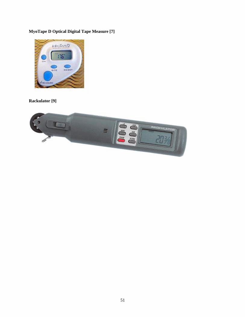
51
MyoTape D Optical Digital Tape Measure [7]
Rackulator [9]
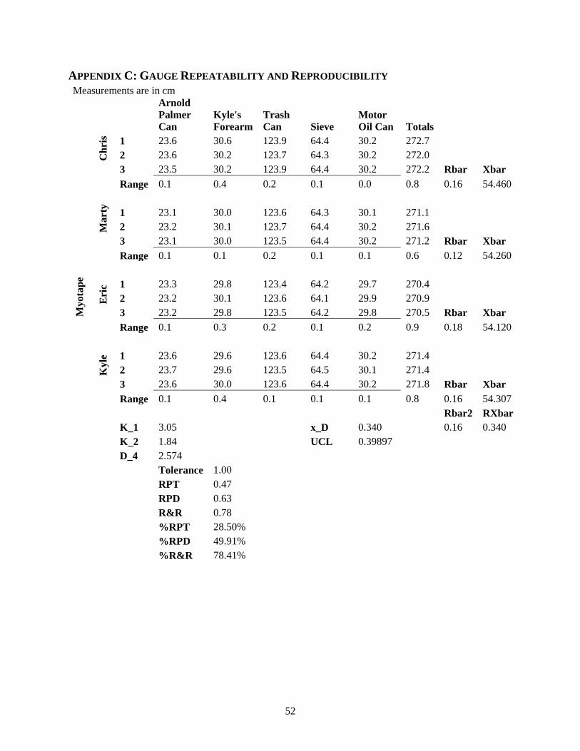
52
APPENDIX C: GAUGE REPEATABILITY AND REPRODUCIBILITY Measurements are in cm
Arnold Palmer Can
Kyle's Forearm
Trash Can Sieve
Motor Oil Can Totals
Myo
tape
Chr
is
1 23.6 30.6 123.9 64.4 30.2 272.7 2 23.6 30.2 123.7 64.3 30.2 272.0
3 23.5 30.2 123.9 64.4 30.2 272.2 Rbar Xbar
Range 0.1 0.4 0.2 0.1 0.0 0.8 0.16 54.460
Mar
ty
1 23.1 30.0 123.6 64.3 30.1 271.1 2 23.2 30.1 123.7 64.4 30.2 271.6
3 23.1 30.0 123.5 64.4 30.2 271.2 Rbar Xbar
Range 0.1 0.1 0.2 0.1 0.1 0.6 0.12 54.260
Eri
c 1 23.3 29.8 123.4 64.2 29.7 270.4 2 23.2 30.1 123.6 64.1 29.9 270.9
3 23.2 29.8 123.5 64.2 29.8 270.5 Rbar Xbar
Range 0.1 0.3 0.2 0.1 0.2 0.9 0.18 54.120
Kyl
e 1 23.6 29.6 123.6 64.4 30.2 271.4 2 23.7 29.6 123.5 64.5 30.1 271.4
3 23.6 30.0 123.6 64.4 30.2 271.8 Rbar Xbar
Range 0.1 0.4 0.1 0.1 0.1 0.8 0.16 54.307
Rbar2 RXbar
K_1 3.05
x_D 0.340
0.16 0.340
K_2 1.84
UCL 0.39897
D_4 2.574
Tolerance 1.00
RPT 0.47
RPD 0.63
R&R 0.78
%RPT 28.50%
%RPD 49.91%
%R&R 78.41%

53
Measurements are in cm
Arnold Palmer Can
Kyle's Forearm
Trash Can Sieve
Motor Oil Can Totals
Stan
dard
Clo
th T
ape
Mea
sure
Chr
is
1 23.2 30.3 123.4 64.5 30.2 271.6 2 23.2 30.5 123.2 64.5 30.2 271.6 3 23.2 30.7 123.6 64.6 30.1 272.2 Rbar Xbar
Range 0.0 0.4 0.4 0.1 0.1 1.0 0.20 54.360
Mar
ty
1 23.2 30.1 123.3 64.6 30.1 271.3 2 23.3 30.4 123.2 64.6 30.2 271.7 3 23.2 30.2 123.4 64.6 30.0 271.4 Rbar Xbar
Range 0.1 0.3 0.2 0.0 0.2 0.8 0.16 54.293
Eri
c
1 23.1 29.9 123.2 64.5 30.1 270.8 2 23.2 30.0 123.2 64.5 30.0 270.9 3 23.1 30.3 123.1 64.5 30.1 271.1 Rbar Xbar
Range 0.1 0.4 0.1 0.0 0.1 0.7 0.14 54.187
Kyl
e
1 23.2 30.2 123.2 64.6 30.2 271.4 2 23.3 30.4 123.5 64.6 30.3 272.1 3 23.3 30.3 123.2 64.7 30.2 271.7 Rbar Xbar
Range 0.1 0.2 0.3 0.1 0.1 0.8 0.16 54.347
Rbar2 RXbar
K_1 3.05
x_D 0.173
0.17 0.173
K_2 1.84
UCL 0.42471
D_4 2.574
Tolerance 1.00
RPT 0.50
RPD 0.32
R&R 0.60
%RPT 42.51%
%RPD 17.07%
%R&R 59.58%

54
Measurements are in cm
Gatorade Bottle Post
2 liter bottle
Orange Juice Totals
Prot
otyp
e
Chr
is
1 23.12 18.71 34.37 19.84 96.04 2 23.07 18.79 34.59 19.52 95.97 3 23.27 18.71 34.56 19.72 96.26 Rbar Xbar
Range 0.20 0.08 0.22 0.32 0.82 0.21 24.023
Mar
ty
1 23.47 18.66 34.22 19.55 95.90 2 23.54 18.66 34.76 20.02 96.98 3 23.62 18.84 34.73 19.79 96.98 Rbar Xbar
Range 0.15 0.18 0.54 0.47 1.34 0.34 24.155
Eri
c
1 23.64 18.81 34.22 20 96.67 2 23.39 18.96 34.25 19.97 96.57 3 23.49 18.94 34.59 20.12 97.14 Rbar Xbar
Range 0.25 0.15 0.37 0.15 0.92 0.23 24.198
Kyl
e
1 23.57 18.86 34.2 19.49 96.12 2 23.22 18.94 34.54 19.72 96.42 3 23.54 18.96 34.58 19.59 96.67 Rbar Xbar
Range 0.35 0.10 0.38 0.23 1.06 0.27 24.101
Rbar2 RXbar
K_1 3.05
x_D 0.176
0.26 0.176
K_2 1.84
UCL 0.6660225
D_4 2.574
Tolerance 1.00
RPT 0.79
RPD 0.32
R&R 0.85
%RPT 73.02%
%RPD 12.27%
%R&R 85.29%

55
APPENDIX D: PATENT DESCRIPTIONS AND FIGURES Information Sources Patents for tape measures with digital displays were first filed in the mid 1970s. In the last 40 years, the technology in tape measures has changed, but their basic internal mechanisms remained the same. There have been many different methods used to determine the length of the extended tape, some of which include: electronic calculators; optical encoders working in unison with electronic logic circuitry; a system of magnetic and non-magnetic balls; and optical encoding disks containing switches. The first patent for a digital tape measure in 1975 lacked additional features, but as time passed, more features have been added, including: zeroing, braking mechanisms, reverse motors, methods for determining accuracy, and many more. Table D below has a short description of each patent.
Table D: Summary of historical patents on digital tape measures Pat. No. Year Description Website 4031360 1975 Metal tape, spring-based wheel; included calculator to add
lengths together http://bit.ly/c8l9w4
4242574 1978 Optical encoder with encoded tape; displays metric and English units; had a tare function
http://bit.ly/cC5EMz
4316081 1982 First patent for digital tape measure with flexible tape; used magnetic balls to calculate extended length
http://bit.ly/dAK0Iy
4551847 1985 Many additional features than previous designs, including a lock and a variable speed reverse motor; used a sprocket with an optical encoder that rolled as tape moved in or out
http://bit.ly/cOrSUa
5386643 1995 First tape measure to have an accuracy specification; had encoded holes that spun a sprocket that was read by an optical sensor
http://bit.ly/akgR4W
6868620 2005 Very complex, flexible tape design with over 150 parts; also uses an optical encoder to determine length of extended tape. An image of this patent can be found in figure D (a, b)
http://bit.ly/av3m56
Figure D (a, b): Patent 6868620 from 2005 is a patent for a digital tape measure with a flexible tape; it is extremely complicated, as seen in (b) (a) (b)
The first patent for a digital display tape measure was filed in 1975 [18] for a tape measure that used a metallic tape mounted on a spring-biased reel, wound into a coil within a housing unit. This tape measure

56
included an electronic calculator used to add fixed multiples of length as the tape was extended. A digital display was connected to the calculator, displaying how much tape was extended.
In 1978, a slightly different digital tape measure with improvements over the previous one was patented [19]. In order to digitally display the measurement, it used an optical encoder to sense markings along the length of the tape. As the markings passed by the optical light sensor, they were counted by electronic logic circuitry which controlled the digital display where the measurements were outputted. The tape measure was capable of displaying both metric and English units by having two sets of markings that were placed along the length of tape. This tape measure also included an option to zero the measurement, which reset the measurement to zero and measured any additional lengths from the new reference point.
The first patent for a digital tape measure that used a flexible measuring tape was patented in 1982 [20]. It was essentially a calculator that included a tape that extended from its bottom corner. To determine the extended length, it used magnetic balls in a predetermined space from each other. By locating non-magnetic balls, it was able to determine the space in between. The measurement of the extended length of the flexible tape was displayed on the digital readout of the calculator.
A more feature rich digital tape measure was patented in 1985 [21]. It included a sprocket that contacted the surface of the tape to ensure that the tape would not slip and an encoding disk to determine the length of the extended tape. The encoding disk used energy sensitive coupler switches mounted to electrical outputs. The rotation of the encoding disk was directly proportional to the extension of the tape, so as the disk rotated, the switches sent a signal to an electronic circuit, which then outputted the measurement to a digital display. Depending on the rotation of the encoding disk, the tape measure was able to determine if it was being extended or retracted. This tape measure also included a variable speed reverse motor as well as a lock for holding the tape in the extended position.
In 1995 [22], the first digital tape measure that included a specification for accuracy was patented. It was a digital tape measure with an accuracy of approximately 0.01 mm. Like most of the previous tape measures, it was comprised of a metal tape wound inside of a housing unit. This tape measure had a series of holes positioned along the centerline of the tape that were used to engage pins on a sprocket which caused it to rotate which then caused an optical encoder to rotate. The optical encoder produced pulses to provide the desired accuracy and was also used to determine the extended length of the tape.
The most recent patent of a tape measure with a flexible tape and digital display was patented in 2005 [23]. The design of this tape measure was more complicated and contained many more components than the previous tape measures. Like the previous tape measures, it uses an optical encoder to determine the length of the extended tape.
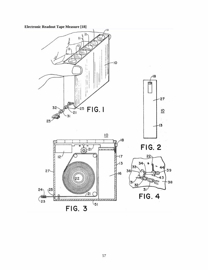
57
Electronic Readout Tape Measure [18]

58
Digital Display Tape Measure with Photoelectric Sensing of Tape Displacement [19]

59
Electronic Digital Tape Measure Having Flexible Measuring Tape [20]

60
Hand Held Digital Measuring Device [21]

61
Digital Display Tape Measure [22]

62
Digital Measuring Instrument Having Flexible Measuring Line [23]
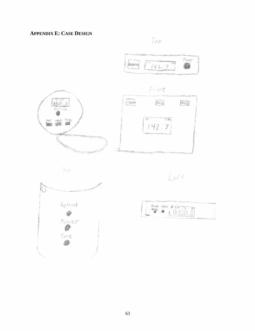
63
APPENDIX E: CASE DESIGN

64
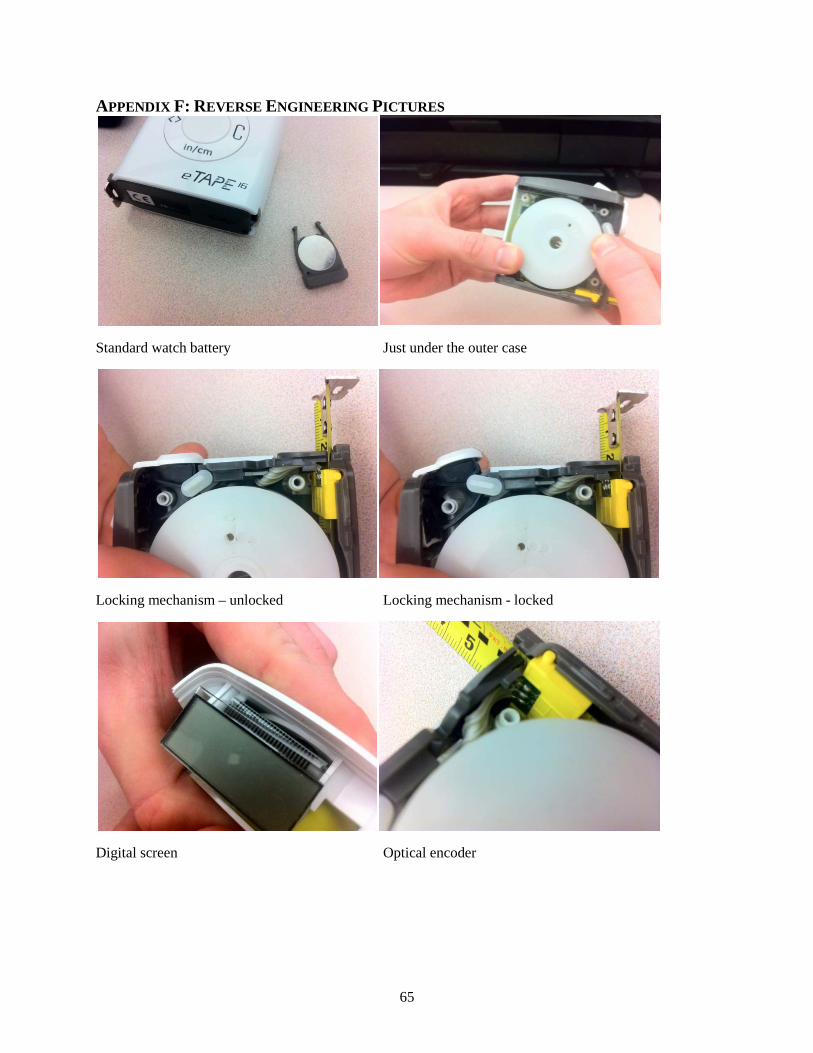
65
APPENDIX F: REVERSE ENGINEERING PICTURES
Standard watch battery Just under the outer case
Locking mechanism – unlocked Locking mechanism - locked
Digital screen Optical encoder
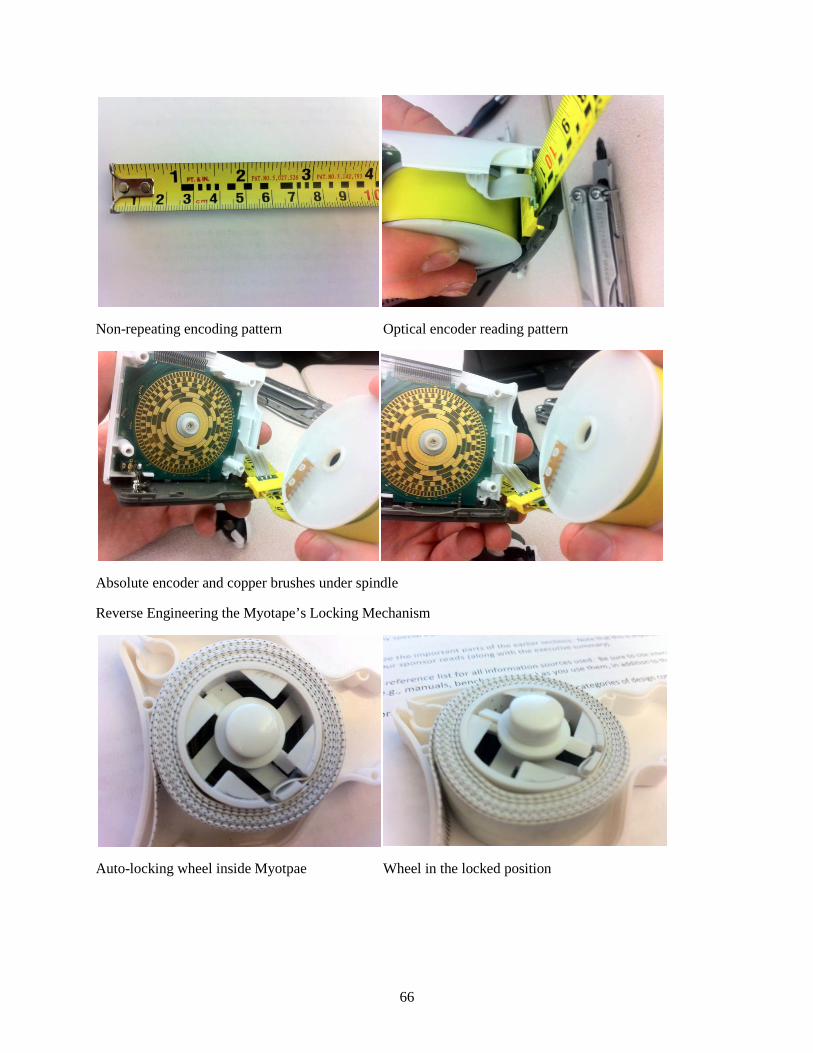
66
Non-repeating encoding pattern Optical encoder reading pattern
Absolute encoder and copper brushes under spindle
Reverse Engineering the Myotape’s Locking Mechanism
Auto-locking wheel inside Myotpae Wheel in the locked position

67
Wheel without lock button
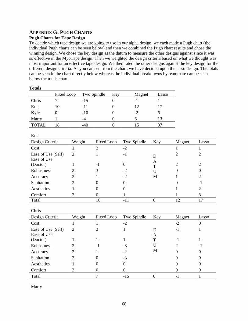
68
APPENDIX G: PUGH CHARTS Pugh Charts for Tape Design To decide which tape design we are going to use in our alpha design, we each made a Pugh chart (the individual Pugh charts can be seen below) and then we combined the Pugh chart results and chose the winning design. We chose the key design as the datum to measure the other designs against since it was so effective in the MyoTape design. Then we weighted the design criteria based on what we thought was most important for an effective tape design. We then rated the other designs against the key design for the different design criteria. As you can see from the chart, we have decided upon the lasso design. The totals can be seen in the chart directly below whereas the individual breakdowns by teammate can be seen below the totals chart.
Totals
Fixed Loop Two Spindle Key Magnet Lasso
Chris 7 -15 0 -1 1 Eric 10 -11 0 12 17 Kyle 0 -10 0 -2 6 Marty 1 -4 0 6 13 TOTAL 18 -40 0 15 37 Eric
Design Criteria Weight Fixed Loop Two Spindle Key Magnet Lasso Cost 1 2 -2
D A T U M
1 1 Ease of Use (Self) 2 1 -1 2 2 Ease of Use (Doctor) 1 -1 0 2 2 Robustness 2 3 -2 0 0 Accuracy 2 1 -2 1 2 Sanitation 2 0 0
0 -1
Aesthetics 1 0 0
1 2 Comfort 2 0 1
1 3
Total
10 -11 0 12 17 Chris
Design Criteria Weight Fixed Loop Two Spindle Key Magnet Lasso Cost 1 1 -2
D A T U M
-2 0 Ease of Use (Self) 2 2 1 -1 1 Ease of Use (Doctor) 1 1 1 -1 1 Robustness 2 -1 -3 2 -1 Accuracy 2 1 -2 0 0 Sanitation 2 0 -3 0 0 Aesthetics 1 0 0
0 0
Comfort 2 0 0
0 0 Total
7 -15 0 -1 1
Marty

69
Design Criteria Weight Fixed Loop Two Spindle Key Magnet Lasso Cost 1 -1 -3
D A T U M
1 1 Ease of Use (Self) 2 2 1 1 2 Ease of Use (Doctor) 1 2 1 1 2 Robustness 2 0 -1 1 1 Accuracy 2 1 1 0 2 Sanitation 2 -1 -2 0 0 Aesthetics 1 0 0 0 0 Comfort 2 0 0 0 0 Total
1 -4 0 6 13
Kyle Design Criteria Weight Fixed Loop Two Spindle Key Magnet Lasso
Cost 1 0 -2
D A T U M
-2 -1 Ease of Use (Self) 2 2 -2 -1 -1 Ease of Use (Doctor) 1 2 -2 0 1 Robustness 2 1 0 0 -1 Accuracy 2 -3 0 0 3 Sanitation 2 -1 -1 1 2 Aesthetics 1 0 0 0 0 Comfort 2 0 0 0 0 Total
0 -10 0 -2 6
Pugh Chart for Locking Mechanism
Design Criteria Weight Automatic Locking User Locking Auto-Locking Wheel Hole in Tape Pinch Locking Magnet
Robustness 2
DA
TUM
-2 2 -3 Reliability 2 -1 -1 -3 Accurate Measurements 2 -1 0 1 Ease of Use 2 -3 -1 -1 Cost 1 1 -1 -3
Total - 0 -13 -1 -15
For the locking mechanism, we only made one Pugh chart as a group since there were fewer choices. We chose the auto-locking wheel concept as the datum since it is so effective in the MyoTape design. We then evaluated the hole in tape design, the pinch locking design, and the magnet design against the auto-locking wheel based on design criteria which we felt were most important for an adequate locking mechanism. We also weighted the design criteria on a two point scale. As you can see from the chart above, none of the concepts beat the auto-locking wheel (datum) so that is the design we will choose for our prototype.

70
Pugh Chart for Constant Tension Devices Design Criteria Weight Power Spring Linear Spring DC Motor Cost 2
DA
TUM
1 -3 Easy to implement 1 -2 -2 Easy to manufacture 2 -1 2 Easy to use 1 0 1 Total - - -2 -3
We used the same method for determining the best constant tension device as described in the locking mechanism concept selection section above. We chose the power spring for the datum since it seemed to be an industry standard and rated using a linear spring and DC motor against it based on the design criteria we felt were most important for the constant tension device. As you can see from the table, we will use a power spring in our prototype.

71
APPENDIX H: CAMBRIDGE ENGINEERING SELECTOR Table H: CES Material Search Criteria Criteria Minimum Value Maximum Value Price $0/lb $1.50/lb Density 0.03 lb/in3 0.04 lb/in3 Yield Strength 5000 psi 6000 psi Tensile Strength 4000 psi 5000 psi Flexural Modulus* 0.2 x 10⁶ psi 0.3 x 10⁶ psi *Flexural modulus is the stress required for a material to bend

72
Figure H: Blue Shaded Circles Meet All Search Criterion
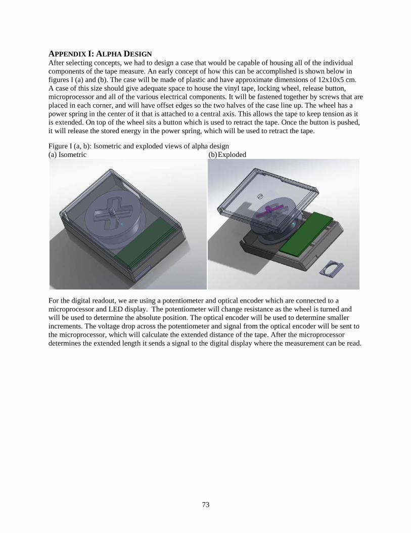
73
APPENDIX I: ALPHA DESIGN After selecting concepts, we had to design a case that would be capable of housing all of the individual components of the tape measure. An early concept of how this can be accomplished is shown below in figures I (a) and (b). The case will be made of plastic and have approximate dimensions of 12x10x5 cm. A case of this size should give adequate space to house the vinyl tape, locking wheel, release button, microprocessor and all of the various electrical components. It will be fastened together by screws that are placed in each corner, and will have offset edges so the two halves of the case line up. The wheel has a power spring in the center of it that is attached to a central axis. This allows the tape to keep tension as it is extended. On top of the wheel sits a button which is used to retract the tape. Once the button is pushed, it will release the stored energy in the power spring, which will be used to retract the tape.
Figure I (a, b): Isometric and exploded views of alpha design (a) Isometric (b) Exploded
For the digital readout, we are using a potentiometer and optical encoder which are connected to a microprocessor and LED display. The potentiometer will change resistance as the wheel is turned and will be used to determine the absolute position. The optical encoder will be used to determine smaller increments. The voltage drop across the potentiometer and signal from the optical encoder will be sent to the microprocessor, which will calculate the extended distance of the tape. After the microprocessor determines the extended length it sends a signal to the digital display where the measurement can be read.

74
APPENDIX J: BILL OF MATERIALS Bill of Materials
Item Quantity Source Catalog Number/SKU
Cost Notes
MyoTape Body Tape Measure 2 http://amzn.to/aTggml $9.40 Use power spring, spindle, and locking mechnism from this device.
Avago HEDS-5605#A06 optical encoder 1 http://bit.ly/bhqLb0 $51.04 Optical encoder, can be purchased for as little as $30.62 when bought in bulk (orders over 5000)
Serial Enabled 16x2 LCD - Yellow on Blue 5V 1 http://bit.ly/bqKb1T $24.95 LCD with backpack for easy Arduino interface
Serpac 273 GRAY case 1 http://bit.ly/aBH1Yv $12.28 Standard electronics case with 9V battery compartment
Black ABS - 6" x 6" - 8586K812 1 http://bit.ly/aNfUXl $15.50 DC/DC Converter Breakout 1 http://bit.ly/bjhZge $21.95 Breakout board attached Chain links 1 Home Depot n/a $0.65 Silver, thin chain Gorilla Super Glue 1 Home Depot n/a $5.97 Plastic epoxy 1 Home Depot n/a $4.99 Plastic to plastic 9 V battery holder 1 Radioshack n/a $2.99 Electrical switch 1 Radioshack n/a $3.49 Singer Fabric tape measure 1 Meijer n/a $1.99 60 inches Duracell 9 V battery 2-pack 1 Meijer n/a $4.97 Total $160.17

75
APPENDIX K: PROTOTYPE MATERIALS AND COMPONENTS Our prototype will mostly consist of purchased components taken from other products on the market. We will only be fabricating one component in the machine shop and modifying two others. After all components have been purchased and/or fabricated we will be able to assemble our prototype.
Raw Material Inventory for Manufactured Components Spindle Mount Material – Acrylonitrile butadiene styrene (ABS) Dimensions – 1” x 6” x 6” Purchased from – McMaster Carr
Description: The spindle mount is a component that is housed inside of the plastic enclosure. Its purpose is to provide a mount and stability for the locking wheel and the tape wheel. It will be held onto the plastic enclosure by two screws. It will have a hole drilled through it for a shaft to pass through, a second shaft which will be glued to it to hold the locking wheel, and a dowel pin glued into it for the pinching part of the locking mechanism.
Purchased Components MyoTape [6] Quantity – 2 Purchased from – Amazon.com
Description: The MyoTape is a fabric tape measure that is used to measure the circumference of body parts. It is composed of a plastic case, tape wheel, power spring, shaft, and a release button mechanism, all of which we will be using in our prototype. The MyoTape’s tape is 150 cm in length and is wrapped around the tape wheel which contains the power spring. As the tape is extended the power spring applies a force that is used to retract the tape. The tape wheel has teeth on it that the release button catch as the tape is extended. In order to retract the tape the release button must be pressed.
Serpac Plastic Enclosure [16] Quantity – 2 Material - ABS Plastic Dimensions – 6.88” x 4.88” x 2.5” Purchased from – Allied Electronics Product Number – 882-0273
Description: The plastic enclosure is made to house electrical components and comes with a pre-fabricated spot hold a 9-V battery. It is made of high impact ABS plastic, has circuit board bosses built in, and comes with the screws that are used to hold it together. Common applications include: industrial test equipment, computer interface, telecommunications, and prototype enclosure. The case will have to be machined in order for it to work with our design. We have to drill a hole for the release button, cut out holes for the tape and LCD, and cut screw holes in the bottom to secure the internal components to the case.
Arduino Duemilanove [12] Quantity – 1 Dimensions – 2.7” x 2.1” x 0.75” Purchased from – Provided

76
Description: The Arduino Duemilanove is a microcontroller board with 14 digital input/output pins, 6 analog inputs, a 16 MHz crystal oscillator, a USB connection, a power jack, an ICSP header, and a reset button. It contains everything needed to support the microcontroller and can simply be connected to a computer with a USB cable. The Duemilanove can also be powered with a 9 V battery; it can supply 40 mA of current per pin; and can be programmed using a computer interface. In our prototype it will be used to receive an input signal from the optical encoder and make a calculation from this input. Then it will output a signal to the LCD to display the extended length of tape.
Serial Enabled 16x2 LCD [14] Quantity – 1 Dimensions – 4” x 1.5” x 0.5” Purchased from – SparkFun.com Product Number – LCD-09396
Description: This is a serial LCD that has an integrated circuit board. Included on a single board is a 16x2 LCD and an embedded circuit based around a PIC 16F88. The on-board PIC takes a TTL serial input and prints the characters it receives onto the LCD. This LCD has the ability to dim the backlight to conserve power if needed. There is also a potentiometer on the back of the display to adjust the contrast. In our prototype it will receive signals from the Arduino board to display the length of the extended tape.
DC to DC converter [15] Quantity – 1 Dimensions – 0.5” x 0.5” x 0.5” Purchased from – SparkFun.com Product Number – TOL-09275
Description: This is a SMD non-isolated DC to DC converter that can deliver up to 6A of output current. These modules provide precisely regulated output voltage programmable via external resistor and capacitor from 0.59 VDC to 5.5 VDC over a wide range of input voltage. Their open-frame construction and small footprint enable designers to develop cost- and space-efficient solutions. Standard features include remote On/Off, programmable output voltage and over current protection. In our prototype, the DC to DC converter is used to supply current to the LCD because the Arduino cannot provide enough current.
Avago Technologies HEDM – 5605#A06 [13] Quantity – 1 Dimensions – 1.6” x 1.2” x 0.72” Purchased from – digikey.com Product Number – 516-2024-ND
Description: The HEDM-5605 optical encoder is high performance, low cost, two-channel encoder. It has high reliability, high resolution, and is easy to assemble. This model is small in size and does not contain a shaft so it can be used in our design. It uses quadrature encoding, requires a 5 V input and 17 mA of current, and has a resolution of 500 pulses per minute. Common applications include: printers, tape drives, positioning tables and automatic handlers. It will be connected to the tape wheel via a shaft, so as the tape is extended it turns the shaft so the optical encoder can sense rotation. The encoder outputs its signal to the Arduino board.

77
APPENDIX L: ENGINEERING DRAWINGS OF MACHINED COMPONENTS

78

79

80
APPENDIX M: DESIGN CHANGES SINCE DESIGN REVIEW 3 Switch In our previous design review we did not include a power switch in our design. We realized that a switch to power the tape measure on and off was essential to reset the Arduino, and to improve the ease of functionality. A switch was added that was able to cut the power to all components in the design. The switch we used was purchased from RadioShack and can be found in our bill of materials.
Flipped spindle mount After assembling our design we realized that the locking mechanism could not function properly if it was spinning clockwise. In order to fix this the spindle mount was flipped to allow the locking wheel to spin counterclockwise. Flipping the spindle mount also effected where the tape exited the device. A new hole had to be cut into the case to allow for the tape to exit on the side closer to the side that housed the LCD.
Figure M.1: Design before changes
Figure M.2: Final prototype design after changes

81
APPENDIX N: DESIGN ANALYSIS ASSIGNMENT FROM LECTURE FUNCTIONAL PERFORMANCE Case The function of this component is to house all of the internal components for our device and to protect these internals from damage if it is dropped. The constraints for this component include that it must be plastic due to customer requirements, and must be able to be injection molded for mass production. The density of the material should be less than 0.05 lb/in3 and should have a yield strength of at least 4000 psi and a tensile strength of at least 5000 psi. We used CES Edupack 2010 to determine what five materials best meet these specifications. The top 5 materials that CES returned that meet our specifications are ABS, PVC, Epoxy, Polypropylene, and ASA. We have chosen to use high impact ABS for our case material because it is lightweight, easy to injection mold, is relatively inexpensive, and has high impact resistance as evidenced by its high tensile strength.
Final material: ABS (high-impact, injection molding) (0.1433 lbs used)
Encoder Shaft The function of this component is to connect the tape wheel to the optical encoder so that both components spin with the same angular velocity when the tape is extended. The shaft will be attached to the encoder by using a set screw and will attach to the tape wheel using an adhesive glue. We have chosen to use a metal shaft because using a set screw on a plastic shaft could cause a deformation or crack in the shaft that would decrease the lifetime of the part. We then used CES Edupack 2010 to determine what metals would be acceptable to use for this part. We want this shaft to be lightweight, so we have set a maximum density of 0.3 lb/in3. The cost of this material should be less than $1.00 per pound. The chosen material must also have a high yield strength and tensile strength, so we set the minimum yield strength to 25 ksi and set the minimum tensile strength to 35 ksi. The top 5 materials that CES returned that meet the specifications are aluminum, carbon steel, cast iron, stainless steel, and zinc-aluminum alloy. We have chosen to use a stainless steel shaft because of its high yield and tensile strengths, and because it is a machinable material. We also considered using carbon steel, but many carbon steels are hardened and are very difficult to machine.
Final material: Stainless Steel, Ferritic, AISI 405 (0.0728lbs used)
ENVIRONMENTAL PERFORMANCE After selecting the two materials in the previous section, we used SimaPro 7.2 to determine the environmental impact of using these two materials. We determined that we will use 0.1433lbs of ABS and 0.0728 lbs of stainless steel per unit in our final design. Two comparable materials to the ones chosen in CES were chosen in SimaPro 7.2 and calculations were performed to determine the environmental impact based on the mass of each material used per unit. Figure N.1 on the next page shows the total mass of air and water emissions, use of raw materials, and solid waste.
The total amount of emissions is higher for the ABS plastic case than for the stainless steel encoder shaft. After determining total emissions, we then used the EcoIndicator 99 (EI99) to determine which chosen material has the larger impact on the environment based on each of the EI99 damage classifications. Figure N.2 on the next page shows the output given from SimaPro of a comparison of the amount of damage done to the environment by using the two chosen materials. ABS does more damage in the human health and ecosystem quality categories, while stainless steel does more damage in the resources category.

82
Figure N.1: Total Emissions for ABS vs. Stainless Steel
SimaPro also provides a normalized calculation that shows the overall comparison on the impact on each of the three damage categories. Figure N.3 on the next page shows the normalized score for each material in the three damage categories. Human health is the category that is affected the most by each of the material choices. ABS has almost no effect on the resources category and has a very small effect on the ecosystem quality category compared to human health. Stainless steel has very little effect on the ecosystem quality category, and has a slightly smaller effect on the resources category than it does on the human health category.
Figure N.2: Relative Impacts in Damage Categories – horizontal hatching denotes ABS; vertical hatching denotes stainless steel
0
0.1
0.2
0.3
0.4
0.5
0.6
0.7
0.8
0.9
1
Raw Air Water WasteABS Stainless Steel
Human Health Ecosystem Quality Resources

83
Figure N.3: Normalized Score in Damage Categories – horizontal hatching denotes ABS; vertical hatching denotes stainless steel
Finally, SimaPro weighs the normalized scores and assigns them a point value. The material that has a higher point value after totaling the three categories is considered to have a larger impact on the environment. Not all scores are weighed equally, because the same quantity of two different emissions may have different effects on the environment, therefore the emission that is deemed to be worse for the environment will receive a higher point value. Figure N.4 below shows the total point values for ABS and stainless steel, and shows that ABS receives a point value that is roughly 1.45 times that of stainless steel. From these point values, we can conclude that ABS has a larger impact on the environment than stainless steel.
Figure N.4: Single Score Comparison in Points – horizontal hatching denotes Human Health; vertical hatching denotes Ecosystem Quality; and diagonal hatching denotes Resources
Overall, both of these materials receive relatively low point values for environmental impact. We used the SimaPro function to check if the long term emissions would be larger than the short term emissions and there was no change in point value, so we can conclude that there are no long term effects from using these materials. Finally, we checked into using aluminum as another material option for the encoder shaft
Human Health Ecosystem Quality Resources
ABS Stainless steel

84
and the point value was approximately 14.6 mPt which is greater than twice the value of the stainless steel. Based on these considerations, we would not choose to use a different material for either of our components.
MANUFACTURING PROCESS SELECTION A real world production volume for our product would likely be near 50,000 units. We determined this number by considering our consumer base. Many hospitals and physical therapists that treat patients suffering from edema would use our product and would be the main customer to purchase our product. We also wanted this device to be easy to use so that a patient could purchase it to track their progress in between visits to their physical therapist. This would likely be a smaller target customer base than hospitals and physical therapists. We used CES manufacturing process selector to help determine some viable processes for manufacturing our case and encoder shaft.
Case While using CES, we indicated that this component was a hollow 3-D component that was also non-circular prismatic. The mass range for the case was greater than 0.05 lbs and less than 0.2 lbs and the range of section thickness was greater than 0.02 inches and less than 0.5 inches. Finally, we indicated that we needed a primary shaping process with an economic batch size ranging from 1,000 to 50,000. CES returned 11 different process options, however many of these were casting processes which is used for metal. Because we are using an ABS plastic case, we were left with injection molding for thermoplastics. This satisfies all of the specifications that were discussed above and we believe it is the best option for manufacturing our case.
Encoder Shaft We also used CES to determine a viable manufacturing process for our encoder shaft. We indicated that the component is a 3-D solid and is circular prismatic. The mass range is from 0.05 lb to 0.1 lb and the tolerance of the component ranges from 0.003” to 0.005”. Finally, we specified that the economic batch size ranged from 1,000 to 50,000 units. CES returned 10 different process options, but some had to ignored because they were not able to be used with metal. We decided to use a turning and parting method to manufacture the encoder shaft. A turning tool would be used to ensure the proper diameter of the shaft, and a parting tool would be used to cut the shaft to the proper length. This could be done using a CNC machine, and could use a bar feeder to allow the process to run continuously after it has been set up even if a worker is not always present.

85
APPENDIX O: ARDUINO CODE int val; int encoder0PinA = 2; int encoder0PinB = 3; int encoder0Pos = 0; int encoder0PinALast = LOW; int n = LOW; int count; double distance; double usdistance; void setup() { pinMode (encoder0PinA,INPUT); pinMode (encoder0PinB,INPUT); Serial.begin (9600); } void loop() { n = digitalRead(encoder0PinA); if ((encoder0PinALast == LOW) && (n == HIGH)) { if (digitalRead(encoder0PinB) == LOW) { encoder0Pos--; } else { encoder0Pos++; } } if (count == millis()/5000) { clearLCD(); selectLineOne(); distance = 0.0000005*(encoder0Pos)*(encoder0Pos)+0.0256*(-encoder0Pos)+0.6; Serial.print (distance); Serial.print (" cm "); selectLineTwo(); usdistance = 0.393700787*distance; Serial.print (usdistance); Serial.print (" inches "); count++; } encoder0PinALast = n; } void clearLCD() { Serial.print(0xFE, BYTE); //command flag Serial.print(0x01, BYTE); //clear command. } void selectLineOne() { //puts the cursor at line 0 char 0. Serial.print(0xFE, BYTE); //command flag Serial.print(128, BYTE); //position }

86
void selectLineTwo() { //puts the cursor at line 0 char 0. Serial.print(0xFE, BYTE); //command flag Serial.print(192, BYTE); //position } void goTo(int position) { //position = line 1: 0-15, line 2: 16-31, 31+ defaults back to 0 if (position<16){ Serial.print(0xFE, BYTE); //command flag Serial.print((position+128), BYTE); //position } else if (position<32){ Serial.print(0xFE, BYTE); //command flag Serial.print((position+48+128), BYTE); //position } else { goTo(0); } }

87
APPENDIX P: GANTT CHART

88
APPENDIX Q: BUDGET Budget
Item Where purchased Quantity Cost per item Tax and Shipping Spent
MyoTape Body Tape Measure http://amzn.to/aTggml 2 $5.28 $0.00 $10.56 MABIS Tape Measure http://amzn.to/c2JBMq 1 $3.33 $0.00 $3.33 MyoTape Body Tape Measure http://amzn.to/aTggml 3 $4.70 $0.00 $14.10 eTape Digital Tape Measure http://bit.ly/sE7s3 1 $24.99 $8.69 $33.68 Avago HEDS-5605#A06 http://bit.ly/bhqLb0 1 $51.04 $14.46 $65.50
Serial Enabled 16x2 LCD - Yellow on Blue 5V http://bit.ly/bqKb1T 1 $24.95 $15.00 $39.95 DC to DC converter module 6A http://bit.ly/pF9sM 1 $13.95 $0.00 $13.95 Serpac 273 GRAY http://bit.ly/aBH1Yv 2 $12.28 $11.18 $35.74 Black ABS - 6" x 6" - 8586K812 http://bit.ly/aNfUXl 1 $15.50 $0.00 $15.50 DC/DC Converter Breakout http://bit.ly/bjhZge 1 $21.95 $4.41 $26.36 RETURN: DC to DC converter http://bit.ly/pF9sM 1 -$13.95 $0.00 -$13.95 Molex Jumper 3 Wire assembly http://bit.ly/b6Jhn6 1 $1.50 $0.00 $1.50 1/8" solid aluminum rod Carpenter Bros.
Hardware 1 $0.99 $0.06 $1.05
Aluminum pin 4 $0.30 $0.07 $1.27 120 in tape measure Jo-Ann Fabrics 1 $3.79 $0.23 $4.02 Large D-ring Home Depot 1 $2.39 $0.14 $2.53 Small D-ring Home Depot 1 $2.39 $0.14 $2.53 Chain links Home Depot 1 $0.65 $0.04 $0.69 Rubber Contact liner Home Depot 1 $5.99 $0.36 $6.35 Gorilla Super Glue Home Depot 1 $5.97 $0.36 $6.33 Plastic epoxy Home Depot 1 $4.99 $0.30 $5.29 9 V battery holder Radioshack 1 $2.99 $0.18 $3.17 Electrical switch Radioshack 1 $3.49 $0.21 $3.70 Singer Tape Meijer 2 $1.99 $0.12 $4.10 Duracell 9 V battery 2-pack Meijer 1 $4.97 $0.30 $5.27
Spent
$292.52
Budget left $107.48

89
APPENDIX R: TEAM MEMBER BIOS Marty Lueck I am from Troy, Michigan and have lived in the Metro Detroit area for my entire life. My interest in mechanical engineering began at a young age due to all the engineers that I was surrounded by on an everyday basis. My dad, uncle, and both grandpas are all mechanical engineers, so I was constantly exposed to engineering and found many of their projects and discussions very interesting. I always helped around the house on building projects, and my dad and grandpa would always tell me to “think of a way that we can build or improve this,” which started my interest in engineering. My plans for the future include graduating in May 2011 and I plan on getting a job in industry after completing my undergraduate degree. I may eventually go back to school and get my MBA, but am not sure if I have an interest in a master’s degree in mechanical engineering. In my free time, I enjoy playing and watching sports, especially hockey, football, and golf.
Kyle Schilling I am from Jackson, Michigan, which is approximately 40 minutes outside of Ann Arbor. I have lived in Jackson my entire life. I first began to gain interest in mechanical engineering when I was just entering high school. When I was in middle school my grandparent’s purchased my brothers and I two four wheelers. I had a brother that was three years older and whenever the four wheeler would break down we would try our best to fix it. Most of the time we were not successful and we would end up getting our dad to come help us. I have always enjoyed doing hands on work and once I learned about mechanical engineering I thought it would be a good field of study for me. Upon graduating, I plan on getting a full time job. As of now I plan on working for a few years then I will probably return to school to get an MBA or a master’s in engineering. In my free time I enjoying playing sports and weightlifting, but those activities are currently on hold because I have to have shoulder surgery.

90
Chris Spangler I am from Bloomfield Hills, Michigan, and have lived in the area my entire life. I am a senior in mechanical engineering. I chose engineering because I enjoy math and science and I like learning and figuring out how stuff works. I am not sure what I want to do after senior year. I will either continue my education in grad school or get a full time job. Even if I chose to get a full time job right out of undergrad, I would still return to school someday to get a graduate degree. In my free time, I enjoy hanging out with friends, watching and playing sports, and playing video games. My favorite teams to root for are Michigan Football and Basketball and the Detroit Lions, Tigers and Pistons. My favorite sports to play are softball, basketball, tennis and golf.
Eric Zwart I was born and raised in Grand Rapids, MI. My wife, Andrea, and I just got married in May of this year. She is already graduated and working as a nurse in Brighton, MI. She is also from Grand Rapids. My parents are Tim and Alice, and I have two younger brothers, Ryan and Andrew. My dad is a clinical psychologist and my mom has a teaching degree, which probably leaves you scratching your head as to how I got the good math genes. Interestingly enough, both of my grandfathers were mechanically inclined; my mom’s dad was a carpenter and handyman, and my dad’s dad worked on a printing press and is a talented woodworker. From a young age, I’ve been extremely interested in engineering and how all the stuff around me works. I distinctly remember watching earthmovers and construction workers build a bridge over a river near my grandparents’ condo and working with my Grandpa Zwart in his woodshop. I also remember taking things apart and putting them back together, making sure that everything was back in its place. I really enjoy watching sports, especially Michigan sports. Almost all of my free time is devoted to catching a game or reading up on opinions and analysis on the internet. I also enjoy tinkering with technology and computers, especially gizmos and gadgets. After I graduate in May, I’d like to find a job in industry for a few years. I would prefer to work in the automotive industry for a component supply company. I would like to go back to school at some point to obtain my Masters, either in mechanical engineering or business administration.