me module 2 part 2 - ::gateway engineering education … 14 project report due, project...
TRANSCRIPT

1
INTRODUCTION
This text is developed for the mechanical engineering module of the Fundamentals of
Engineering Design. The purpose of the mechanical engineering module is to acquaint
the students with the field of mechanical engineering and the design process in the
product development. The mechanical engineering module contains two parallel but
integrated portions: one is project-oriented and the other is skill-oriented. The project
portion discusses the design process and the associated engineering principles, and
practices basic mechanical design through team projects. The skill portion emphasized
on the engineering sketches, drawings, and computer-aided design and manufacturing
softwares, which are to be used by the students in completing their projects.
2
MECHANICAL ENGINEERING
In a world without mechanical engineers, a typical day wouldn't be so typical. Just
imaging: No cars, buses, trains, or planes. No entertainment, or telephone conversations
around the world.
Mechanical engineers design, develop, and manufacture machines that produce, transmit,
or use power. Wherever machines are produced or used, there are mechanical engineers.
They play a pivotal role in nearly everything that makes life typical. There is hardly an
area of everyday life that hasn't been influenced by a mechanical engineer somewhere
along the path from invention to installation. Mechanical engineers develop new
technologies and find solutions to the problems of an increasingly global technological
society.
Mechanical engineering design encompass a broad range of activities that culminate in
• the definition of a product, process or service,
• the definition of a manufacturing and production system for products and processes,
• the definition of a framework and rules within which a product, process or service is
used or employed, and
• the disposal of products and waste products resulting from the production and use of
products, processes and services.
Trends in product development:
• Economic competition is becoming more intense and global - products be brought
from conception to market quickly.
• Increased awareness of product safety and issues of liability - safer products.
• Increased awareness of environmental impacts combined with a growing global
population - design of more environmentally friendly products and processes and
disposal or reuse of products at the end of their life.

3
• Products and processes are becoming more complex and more interdisciplinary -
concurrent engineering and team work.
4
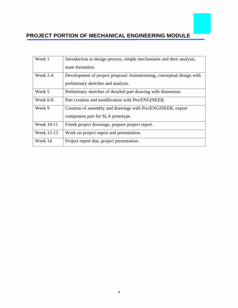
PROJECT PORTION OF MECHANICAL ENGINEERING MODULE
Week 1 Introduction to design process, simple mechanisms and their analysis,
team formation.
Week 2-4 Development of project proposal: brainstorming, conceptual design with
preliminary sketches and analysis.
Week 5 Preliminary sketches of detailed part drawing with dimension.
Week 6-8 Part creation and modification with Pro/ENGINEER.
Week 9 Creation of assembly and drawings with Pro/ENGINEER, export
component part for SLA prototype.
Week 10-11 Finish project drawings, prepare project report.
Week 12-13 Work on project report and presentation.
Week 14 Project report due, project presentation.

5
MECHANICAL DESIGN - AN ITERATIVE PROCESS
Design is a decision-making process: the generation and identification of options, the
estimation of outcomes or expectations for each option, and the use of preferences or
values in the selection of a preferred alternative. All design must be viewed as a matter
of decision making under risk and uncertainty.
• identification of need (market research)
• background research (patent issue)
• project statement: reasonable and realistic (understand the limitations, such as time
and budget constraints)
• task specifications: bound the problem and limit its scope
• synthesis: generate alternatives (example - sprinkler) with sufficient details: shape,
material, dimension, tolerance and finishing
functional
structural
detailed
• evaluation of candidate designs: typically requires various forms of analysis, such as
finite element analysis (FEA), thermal analysis, hydrodynamic analysis, and so on.
accept, reject, or modify the alternatives
engineering calculation (dilemma of initial design!!)
manufacturing consideration
ownership quality (user values: aesthetic appearance, product life, and
serviceability)
multi-life cycle consideration
• selection of the most promising solution
• prototyping and testing
• production

6
Good engineering design means:
quality product, low cost, lower use of energy and natural resources, fast to market,
minimized adverse effects on the environment, etc.
Discussion: optimal design vs. "good enough" and "incremental improvement"
7
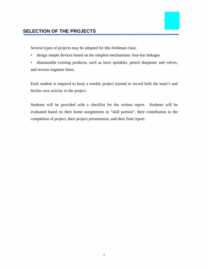
SELECTION OF THE PROJECTS
Several types of projects may be adopted for this freshman class:
• design simple devices based on the simplest mechanisms: four-bar linkages
• disassemble existing products, such as lawn sprinkler, pencil sharpener and valves,
and reverse engineer them.
Each student is required to keep a weekly project journal to record both the team’s and
his/her own activity in the project.
Students will be provided with a checklist for the written report. Students will be
evaluated based on their home assignments in “skill portion”, their contribution to the
completion of project, their project presentation, and their final report.
8
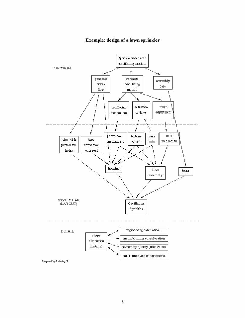
Example: design of a lawn sprinkler
9
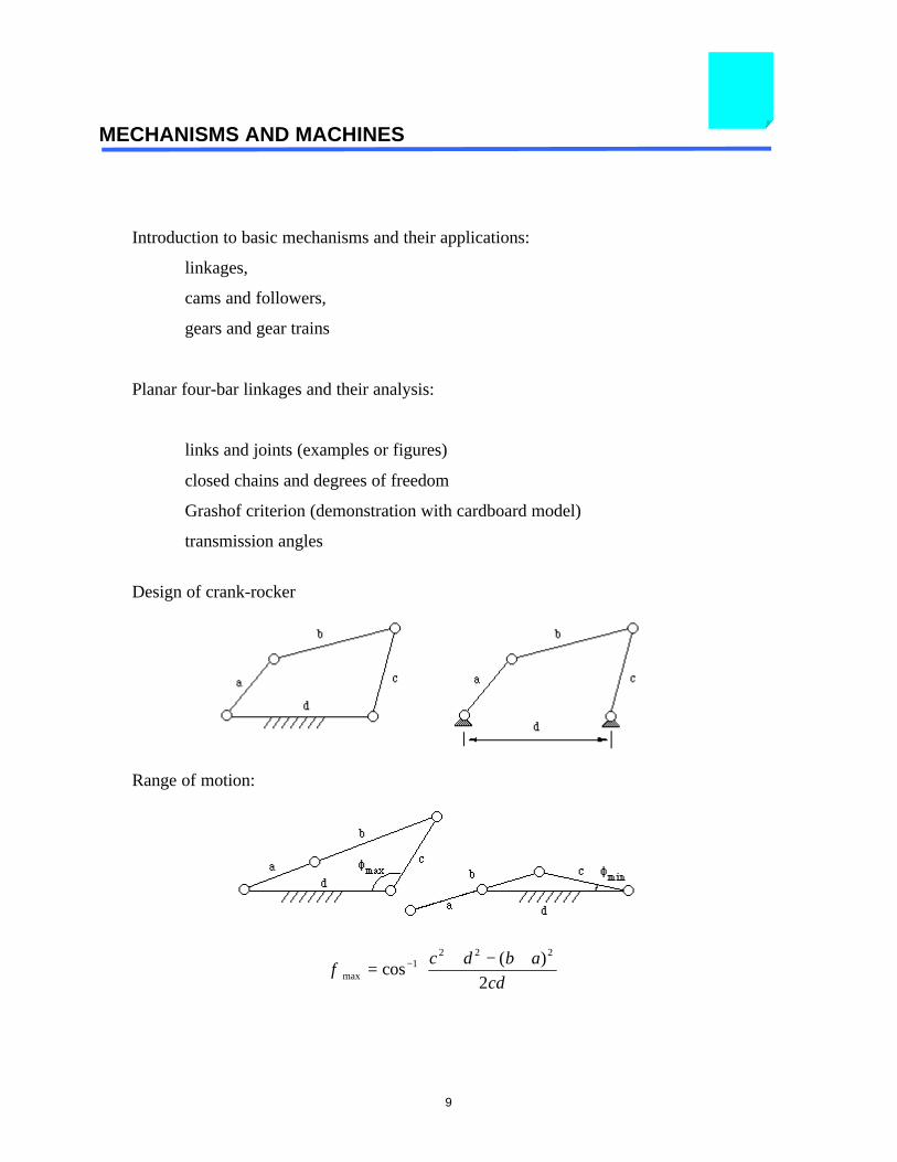
MECHANISMS AND MACHINES
Introduction to basic mechanisms and their applications:
linkages,
cams and followers,
gears and gear trains
Planar four-bar linkages and their analysis:
links and joints (examples or figures)
closed chains and degrees of freedom
Grashof criterion (demonstration with cardboard model)
transmission angles
Design of crank-rocker
Range of motion:
φ max cos( )
=+ − +
−1
2 2 2
2
c d b a
cd
10
φ min cos( )
=+ − −
−1
2 2 2
2
c d b a
cd
Let $aa
d= , $b
b
d= , and $c
c
d= , then
φ max cos$ ( $ $)
$=
+ − +
−1
2 21
2
c b a
c
φ min cos$ ( $ $)
$=
+ − −
−1
2 21
2
c b a
c
Selection of link lengths based on specified range of motion:
two equations and three unknows
don’t forget the Grashof criterion
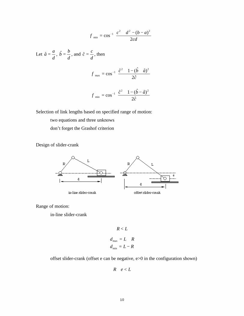
Design of slider-crank
Range of motion:
in-line slider-crank
R L<
d L R
d L Rmax
min
= +
= −
offset slider-crank (offset e can be negative, e>0 in the configuration shown)
R e L+ <
11
d L R e
d L R e
max
min
( )
( )
= + −
= − −
2 2
2 2
According to the need of the individual projects, the following material may be discussed
or provided:
handbooks or catalogs for standard fasteners, connectors
tolerance and fitting
12
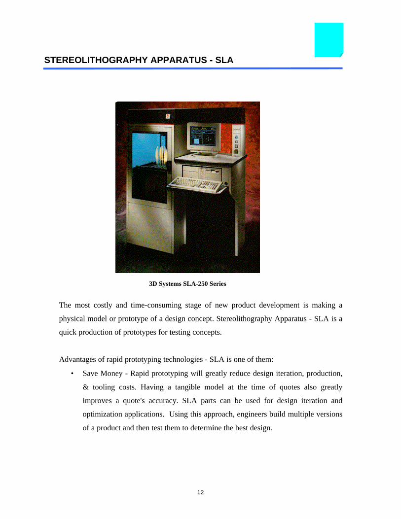
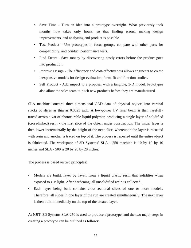
STEREOLITHOGRAPHY APPARATUS - SLA
The most costly and time-consuming stage of new product development is making a
physical model or prototype of a design concept. Stereolithography Apparatus - SLA is a
quick production of prototypes for testing concepts.
Advantages of rapid prototyping technologies - SLA is one of them:
• Save Money - Rapid prototyping will greatly reduce design iteration, production,
& tooling costs. Having a tangible model at the time of quotes also greatly
improves a quote's accuracy. SLA parts can be used for design iteration and
optimization applications. Using this approach, engineers build multiple versions
of a product and then test them to determine the best design.
3D Systems SLA-250 Series
13
• Save Time - Turn an idea into a prototype overnight. What previously took
months now takes only hours, so that finding errors, making design
improvements, and analyzing end product is possible.
• Test Product - Use prototypes in focus groups, compare with other parts for
compatibility, and conduct performance tests.
• Find Errors - Save money by discovering costly errors before the product goes
into production.
• Improve Design - The efficiency and cost-effectiveness allows engineers to create
inexpensive models for design evaluation, form, fit and function studies.
• Sell Product - Add impact to a proposal with a tangible, 3-D model. Prototypes
also allow the sales team to pitch new products before they are manufactured.
SLA machine converts three-dimensional CAD data of physical objects into vertical
stacks of slices as thin as 0.0025 inch. A low-power UV laser beam is then carefully
traced across a vat of photocurable liquid polymer, producing a single layer of solidified
(cross-linked) resin - the first slice of the object under construction. The initial layer is
then lower incrementally by the height of the next slice, whereupon the layer is recoated
with resin and another is traced on top of it. The process is repeated until the entire object
is fabricated. The workspace of 3D Systems’ SLA - 250 machine is 10 by 10 by 10
inches and SLA - 500 is 20 by 20 by 20 inches.
The process is based on two principles:
• Models are build, layer by layer, from a liquid plastic resin that solidifies when
exposed to UV light. After hardening, all unsolidified resin is collected.
• Each layer being built contains cross-sectional slices of one or more models.
Therefore, all slices in one layer of the run are created simultaneously. The next layer
is then built immediately on the top of the created layer.
At NJIT, 3D Systems SLA-250 is used to produce a prototype, and the two major steps in
creating a prototype can be outlined as follows:

14
1. Part created using Pro/ENGINEER will be converted to .stl file, which is a file format
that is understood by SLA machine. The .stl file can be created by using Interface
command available in Pro/ENGINEER.
2. Using ftp (file transfer protocol), the stl file is delivered to the computer that is used
to control SLA machine.
The basic diagram how the Stereolithography works
15
COSTS CALCULATION OF PROTOTYPE
It is a goal of design engineer to develop a product that is at minimal cost, but excellent
in quality. In this section, the costs of producing SLA prototype will be discussed. It is
important to note, the prototype will always be much costly to produce in comparison
with the cost of final product in mass production.
• Estimation guide lines:
1. To build 1” height of prototype in z-direction, it takes 2 - 2.5 hrs of build time.
2. Orient the part in such away so that it’s height in z-direction is minimal.
UNIT COSTS:
(A) Hourly rate for technician labor $14.85(B) Hourly rate for supervision $61.25(C) Hourly rate to build the part $14.86(D) Hourly rate for supplies/recovery costs $1.18(E) One cubic inch of resin $2.28
Note: (B) & (D) are based on technician labor hours.
The material cost of prototype is based on volume, and due to complicated shape of the
product, it is always easier to obtain the volume of the model using Pro/ENGINEER. The
figure shown below is the mass properties generated by Pro/ENGINEER.

16
MASS PROPERTIES OF THE PART PULLEY
VOLUME = 7.3873657e+00 INCH^3 SURFACE AREA = 6.6174595e+01 INCH^2 DENSITY = 4.3300000e-02 POUND / INCH^3 MASS = 3.1987293e-01 POUND
CENTER OF GRAVITY with respect to _PULLEY coordinate frame:X Y Z 0.0000000e+00 0.0000000e+00 0.0000000e+00 INCH
INERTIA with respect to _PULLEY coordinate frame: (POUND * INCH^2)
INERTIA TENSOR:Ixx Ixy Ixz 9.7781480e-01 0.0000000e+00 0.0000000e+00Iyx Iyy Iyz 0.0000000e+00 5.1906349e-01 5.4716553e-07Izx Izy Izz 0.0000000e+00 5.4716553e-07 5.1906308e-01
INERTIA at CENTER OF GRAVITY with respect to _PULLEY coordinate frame: (POUND * INCH^2)INERTIA TENSOR:Ixx Ixy Ixz 9.7781480e-01 0.0000000e+00 0.0000000e+00Iyx Iyy Iyz 0.0000000e+00 5.1906349e-01 5.4716553e-07Izx Izy Izz 0.0000000e+00 5.4716553e-07 5.1906308e-01
PRINCIPAL MOMENTS OF INERTIA: (POUND * INCH^2)I1 I2 I3 5.1906270e-01 5.1906387e-01 9.7781480e-01
ROTATION MATRIX from _PULLEY orientation to PRINCIPAL AXES: 0.00000 0.00000 1.00000 1.00000 0.00000 0.00000 0.00000 1.00000 0.00000
ROTATION ANGLES from _PULLEY orientation to PRINCIPAL AXES (degrees):angles about x y z 0.000 90.000 90.000
RADII OF GYRATION with respect to PRINCIPAL AXES:R1 R2 R3 1.2738584e+00 1.2738599e+00 1.7483950e+00 INCH
Mass Properties of Pro/ENGINEER part.
17
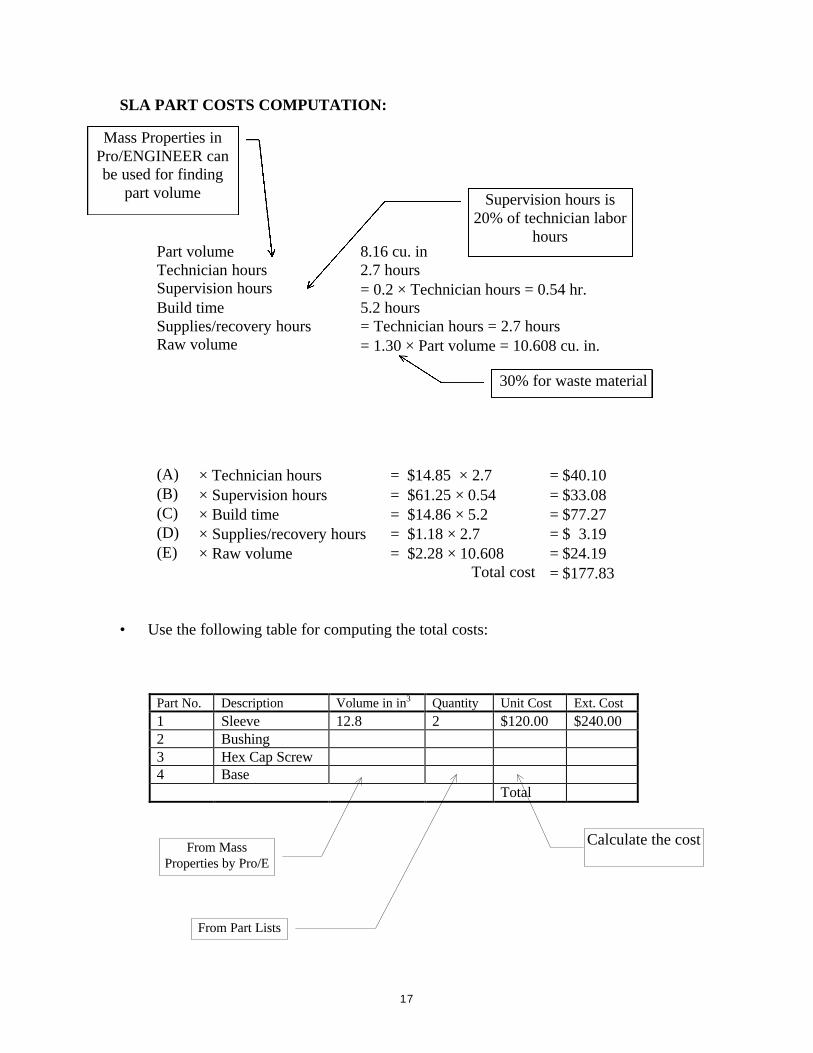
SLA PART COSTS COMPUTATION:
Part volume 8.16 cu. inTechnician hours 2.7 hoursSupervision hours = 0.2 × Technician hours = 0.54 hr.Build time 5.2 hoursSupplies/recovery hours = Technician hours = 2.7 hoursRaw volume = 1.30 × Part volume = 10.608 cu. in.
(A) × Technician hours = $14.85 × 2.7 = $40.10(B) × Supervision hours = $61.25 × 0.54 = $33.08(C) × Build time = $14.86 × 5.2 = $77.27(D) × Supplies/recovery hours = $1.18 × 2.7 = $ 3.19(E) × Raw volume = $2.28 × 10.608 = $24.19
Total cost = $177.83
• Use the following table for computing the total costs:
Part No. Description Volume in in3 Quantity Unit Cost Ext. Cost1 Sleeve 12.8 2 $120.00 $240.002 Bushing3 Hex Cap Screw4 Base
Total
30% for waste material
Supervision hours is20% of technician labor
hours
Mass Properties inPro/ENGINEER canbe used for finding
part volume
From MassProperties by Pro/E
From Part Lists
Calculate the cost
18
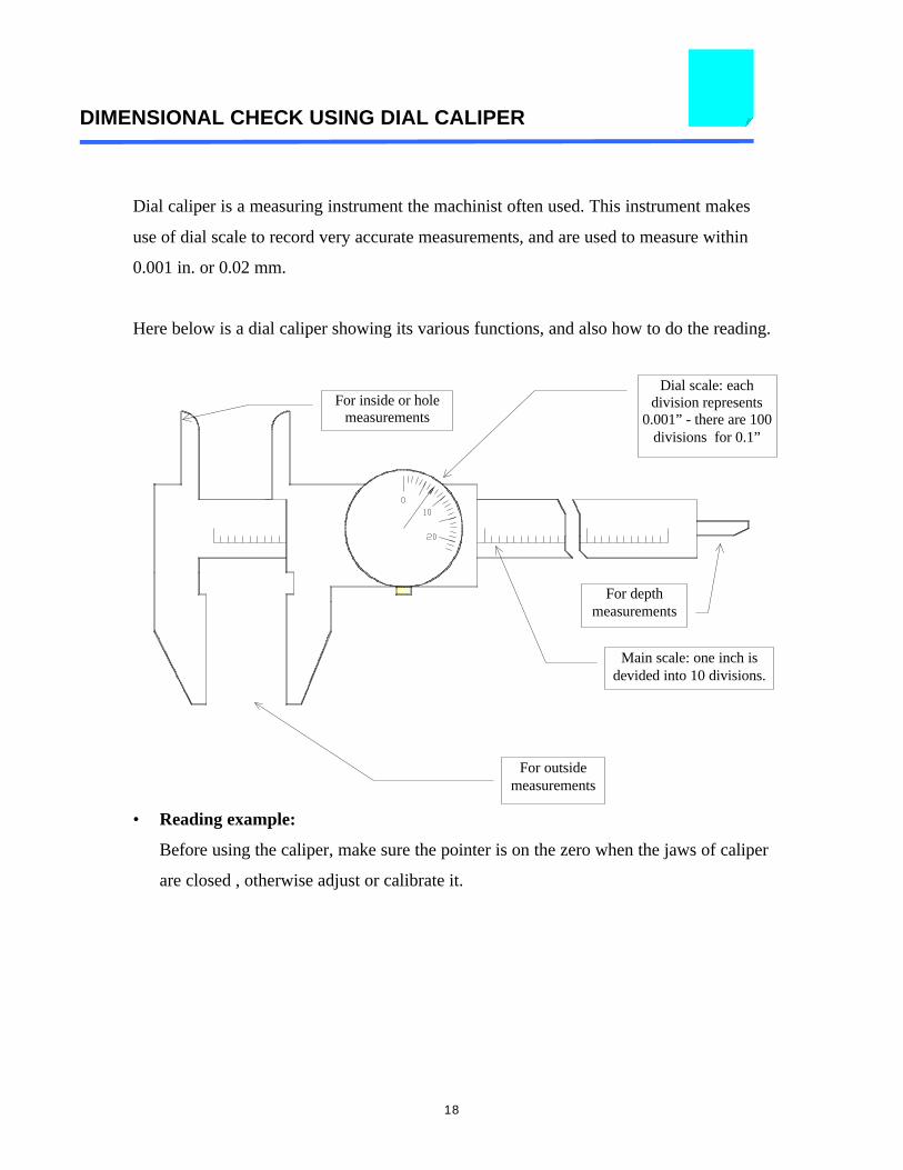
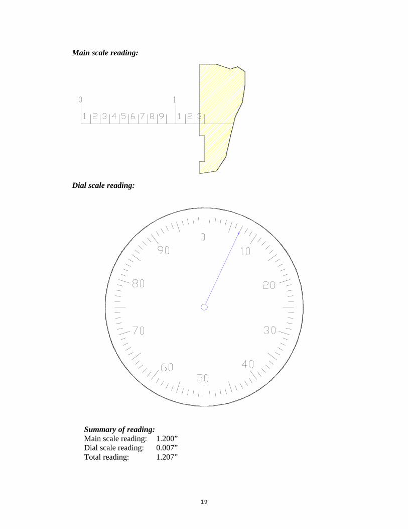
DIMENSIONAL CHECK USING DIAL CALIPER
Dial caliper is a measuring instrument the machinist often used. This instrument makes
use of dial scale to record very accurate measurements, and are used to measure within
0.001 in. or 0.02 mm.
Here below is a dial caliper showing its various functions, and also how to do the reading.
• Reading example:
Before using the caliper, make sure the pointer is on the zero when the jaws of caliper
are closed , otherwise adjust or calibrate it.
For inside or holemeasurements
Dial scale: eachdivision represents
0.001” - there are 100divisions for 0.1”
For depthmeasurements
Main scale: one inch isdevided into 10 divisions.
For outsidemeasurements
19
Main scale reading:
Dial scale reading:
Summary of reading:Main scale reading: 1.200”Dial scale reading: 0.007”Total reading: 1.207”
20
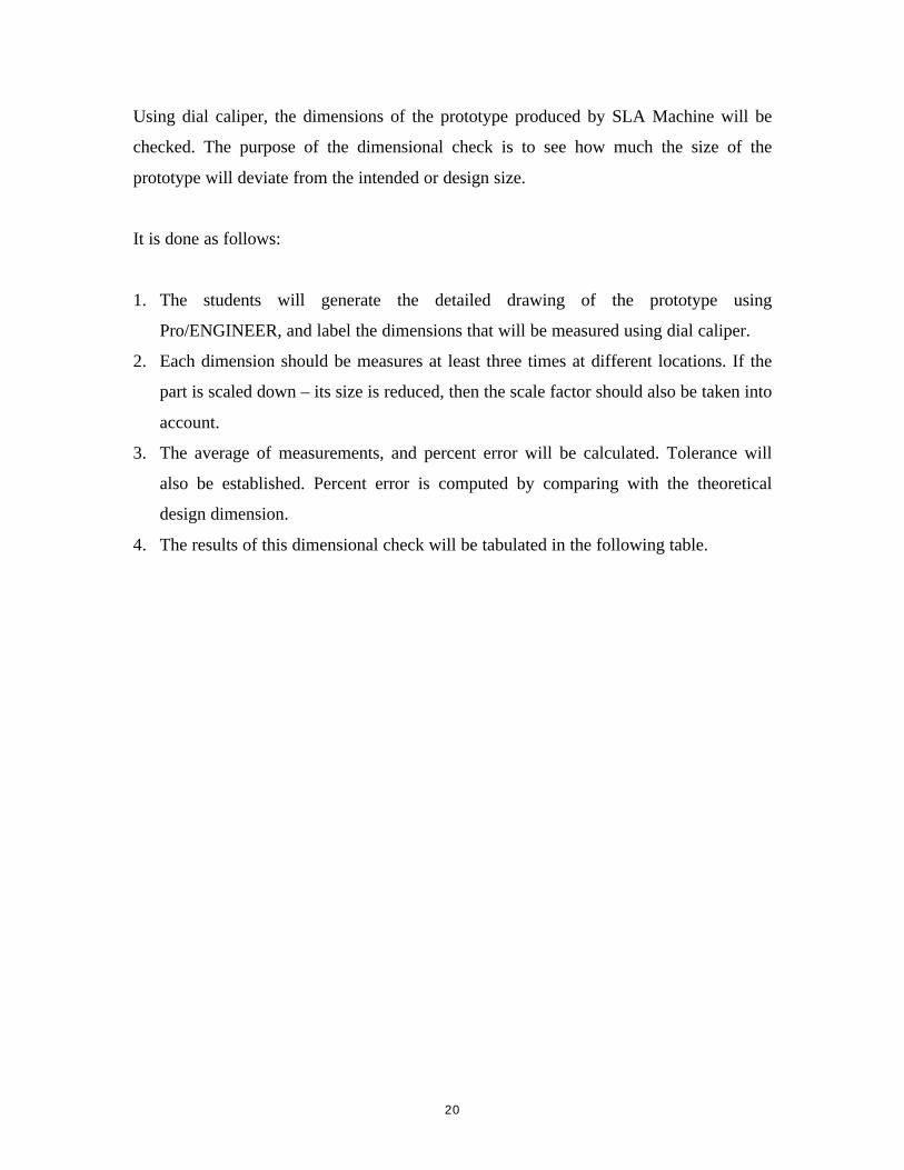
Using dial caliper, the dimensions of the prototype produced by SLA Machine will be
checked. The purpose of the dimensional check is to see how much the size of the
prototype will deviate from the intended or design size.
It is done as follows:
1. The students will generate the detailed drawing of the prototype using
Pro/ENGINEER, and label the dimensions that will be measured using dial caliper.
2. Each dimension should be measures at least three times at different locations. If the
part is scaled down – its size is reduced, then the scale factor should also be taken into
account.
3. The average of measurements, and percent error will be calculated. Tolerance will
also be established. Percent error is computed by comparing with the theoretical
design dimension.
4. The results of this dimensional check will be tabulated in the following table.
21
DIMENSIONAL CHECK OF PROTOTYPE
Part Name: ________________FED -101 Section: __________Dimensions in ______________Semester: __________________
No Design Scale Measured Dimension Percentage ToleranceDimension Dimension First Second Third Average Error
GROUP ______ and members:
1. _____________________________2. _____________________________3. _____________________________4. _____________________________
22
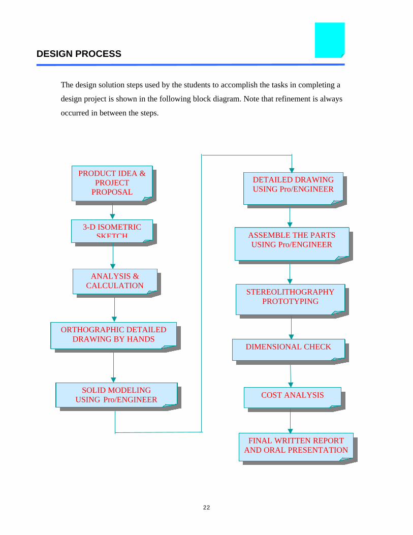
DESIGN PROCESS
The design solution steps used by the students to accomplish the tasks in completing a
design project is shown in the following block diagram. Note that refinement is always
occurred in between the steps.
3-D ISOMETRICSKETCH
PRODUCT IDEA &PROJECT
PROPOSAL
ANALYSIS &CALCULATION
SOLID MODELINGUSING Pro/ENGINEER
DETAILED DRAWINGUSING Pro/ENGINEER
STEREOLITHOGRAPHYPROTOTYPING
ASSEMBLE THE PARTSUSING Pro/ENGINEER
COST ANALYSIS
DIMENSIONAL CHECK
ORTHOGRAPHIC DETAILEDDRAWING BY HANDS
FINAL WRITTEN REPORTAND ORAL PRESENTATION
23
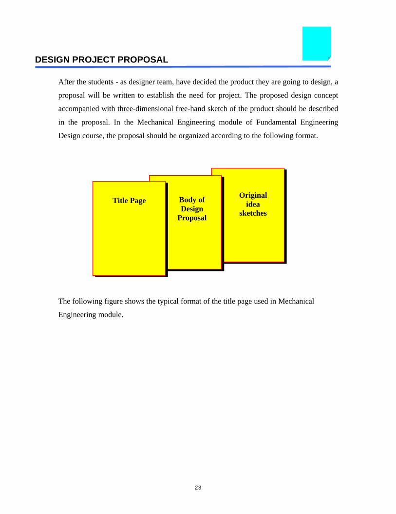
DESIGN PROJECT PROPOSAL
After the students - as designer team, have decided the product they are going to design, a
proposal will be written to establish the need for project. The proposed design concept
accompanied with three-dimensional free-hand sketch of the product should be described
in the proposal. In the Mechanical Engineering module of Fundamental Engineering
Design course, the proposal should be organized according to the following format.
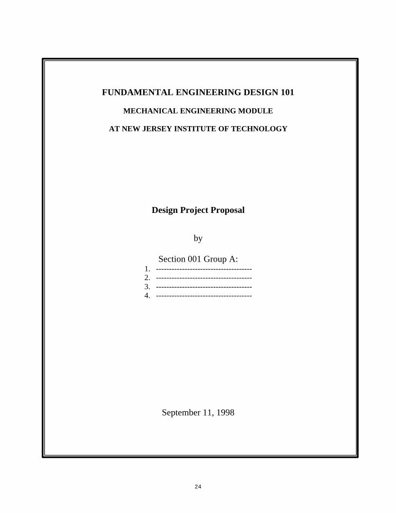
The following figure shows the typical format of the title page used in Mechanical
Engineering module.
Title Page Body ofDesign
Proposal
Originalidea
sketches
24
FUNDAMENTAL ENGINEERING DESIGN 101
MECHANICAL ENGINEERING MODULE
AT NEW JERSEY INSTITUTE OF TECHNOLOGY
Design Project Proposal
by
Section 001 Group A:1. -------------------------------------2. -------------------------------------3. -------------------------------------4. -------------------------------------
September 11, 1998
25
FINAL REPORT AND ORAL PRESENTATION
A very important aspect of engineering is communication of ideas and results. In facts,
engineers write proposals, technical reports, and give presentations. When the design is
done, it is usually necessary to present the results to the clients, peers, or employer in the
form of formal engineering report. Thus, it is important for the engineering student to
develop his or her communication skills.
To give the students some experience in this important skill, the results of design project
assignments should be written up in the form of formal engineering reports. Typically,
the sequence of the report of design project is as follows:
1. Cover Page
2. Title Page
3. Table of Contents
4. List of Figures
5. List of Tables
6. Abstract
7. Introduction
8. Body of Report - Students discretion
9. Conclusion and Recommendations
10. References
11. Appendices
As mentioned above, in addition to write the engineering report, the students will orally
present their results, findings, conclusions and recommendations on their design projects.
Presentation software such as Microsoft Power Point is commonly used in their
presentation.
26
SAMPLES OF STUDENTS’ PROJECT
In this section, the original samples of the student’s project are presented. One of the
projects – The Universal Crusher that employed the principle of slider crank mechanism
will be shown in great detail. Other projects are taken to show the students creativity in
product creation using the principle technique of mechanism. It is important to note here
that the students created all drawings shown in this section. The project description is
also taken from the students’ report.
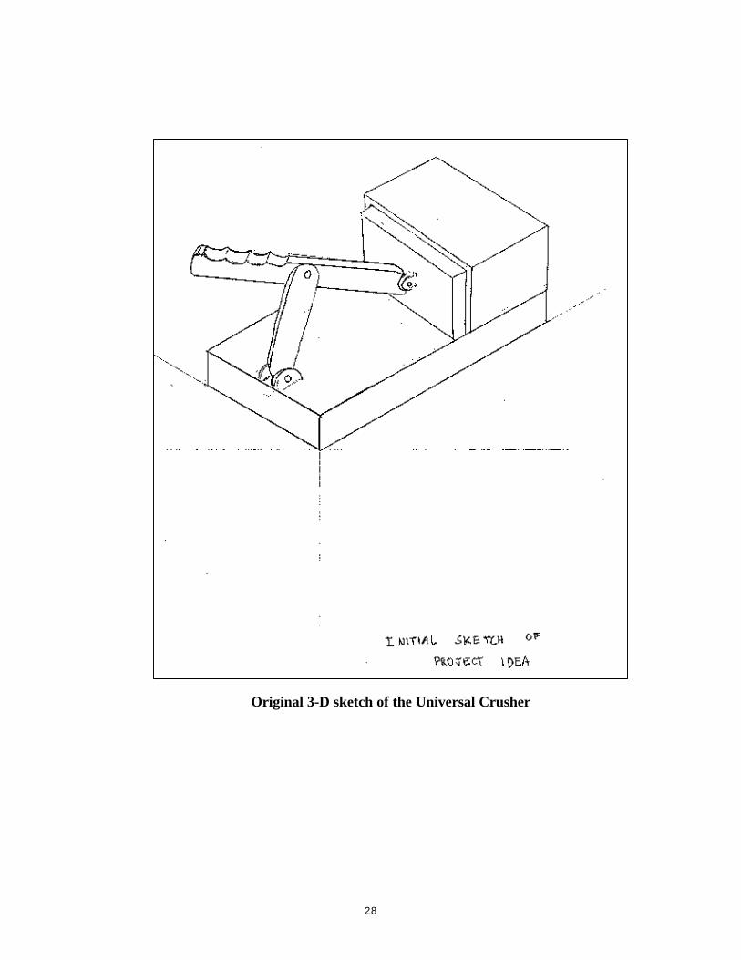
1. THE UNIVERSAL CRUSHER
The universal crusher is a machine of simple design, but its many uses are essential to
daily living. People spend hundreds of dollars buying innumerable little gadgets to do
small jobs in their house. Integrating these machines into one multipurpose unit can
easily solve this problem. The multipurpose, universal crusher resolves this dilemma.
The crusher employs a simple design that is expanded upon to create the functionality
included in this device. The basic design is that of a four bar linkage. This linkage is
laid out in an in-line slider crank fashion. The bar attached to the slider is extended so
that when pressure is applied in a downward motion, the slider moves in a forward
motion. A tongue on the slider inserts into a tongue groove on the base. This controls
the motion of the entire four-bar linkage. The slider moves into a box at the end of the
base that contains the material to be crushed. The material is pushed up against the
back wall of box causing it to be crushed. The back end of this box is removable
adding multiple functions to the crusher. It allows for easy insertion and removal of
the material being crushed. It can also be replaced with different blades to increase
the functionality of the crusher. This is the basic design of the universal crusher.
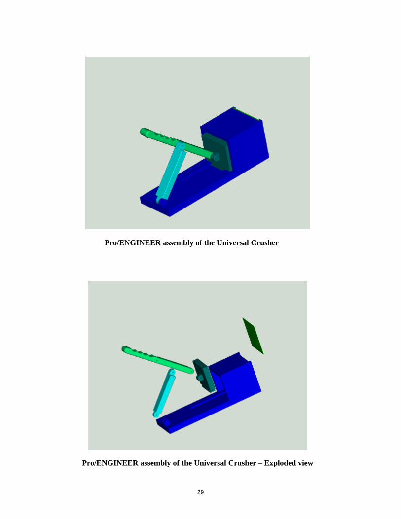
The universal crusher consists of five basic parts. The first is a base. The base has a
connection for on of the arms of the four bar linkage, a tongue groove to hold and
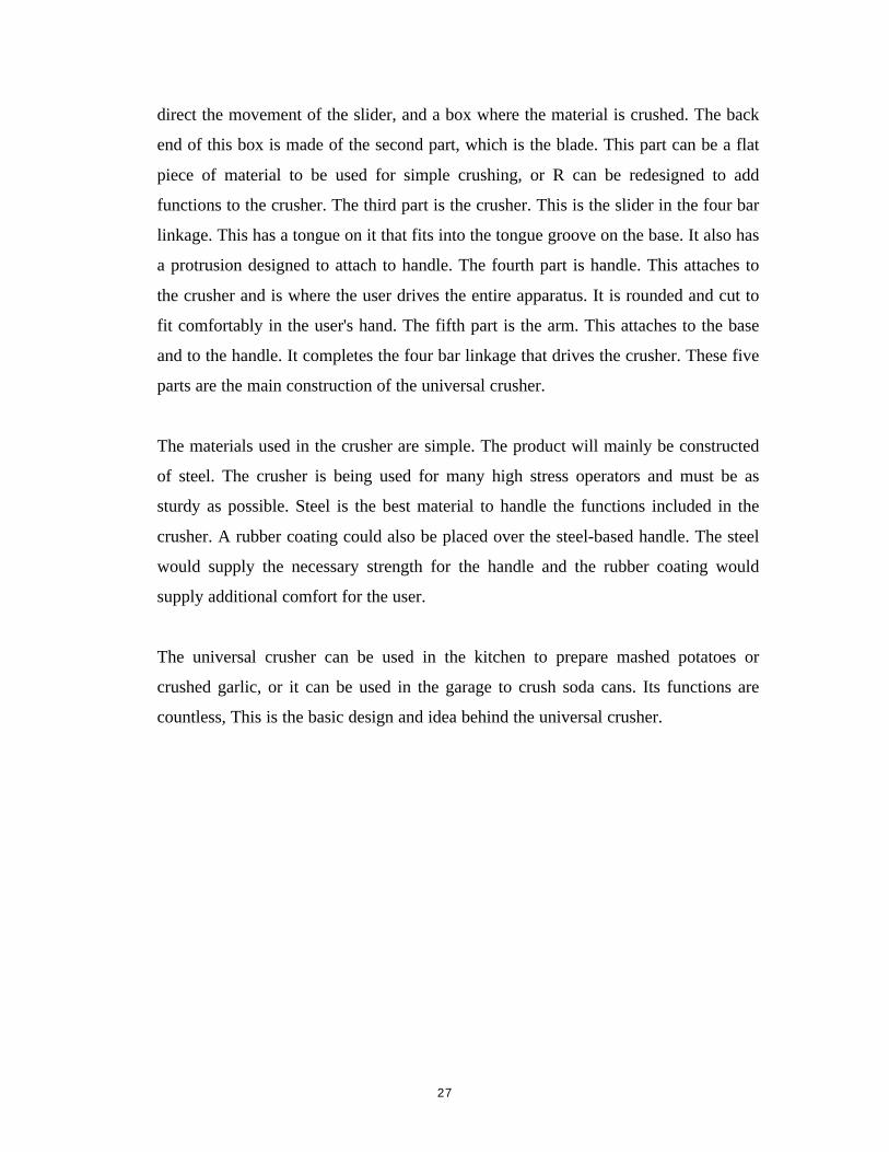
27
direct the movement of the slider, and a box where the material is crushed. The back
end of this box is made of the second part, which is the blade. This part can be a flat
piece of material to be used for simple crushing, or R can be redesigned to add
functions to the crusher. The third part is the crusher. This is the slider in the four bar
linkage. This has a tongue on it that fits into the tongue groove on the base. It also has
a protrusion designed to attach to handle. The fourth part is handle. This attaches to
the crusher and is where the user drives the entire apparatus. It is rounded and cut to
fit comfortably in the user's hand. The fifth part is the arm. This attaches to the base
and to the handle. It completes the four bar linkage that drives the crusher. These five
parts are the main construction of the universal crusher.
The materials used in the crusher are simple. The product will mainly be constructed
of steel. The crusher is being used for many high stress operators and must be as
sturdy as possible. Steel is the best material to handle the functions included in the
crusher. A rubber coating could also be placed over the steel-based handle. The steel
would supply the necessary strength for the handle and the rubber coating would
supply additional comfort for the user.
The universal crusher can be used in the kitchen to prepare mashed potatoes or
crushed garlic, or it can be used in the garage to crush soda cans. Its functions are
countless, This is the basic design and idea behind the universal crusher.
28
Original 3-D sketch of the Universal Crusher
29
Pro/ENGINEER assembly of the Universal Crusher
Pro/ENGINEER assembly of the Universal Crusher – Exploded view
30
Pro/ENGINEER solid model of component part of theUniversal Crusher - Arm
Pro/ENGINEER solid model of component part of theUniversal Crusher - Base
31
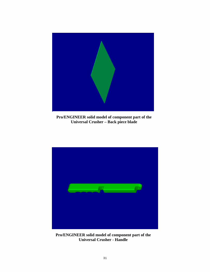
Pro/ENGINEER solid model of component part of theUniversal Crusher – Back piece blade
Pro/ENGINEER solid model of component part of theUniversal Crusher - Handle
32
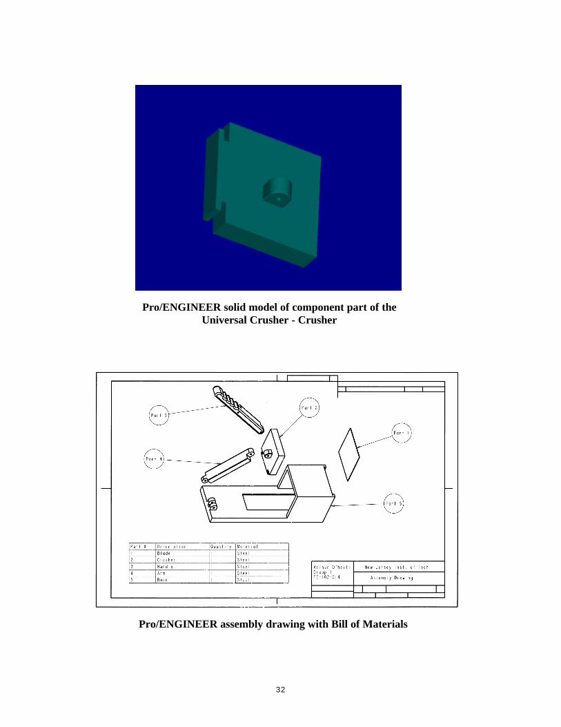
Pro/ENGINEER solid model of component part of theUniversal Crusher - Crusher
Pro/ENGINEER assembly drawing with Bill of Materials
33
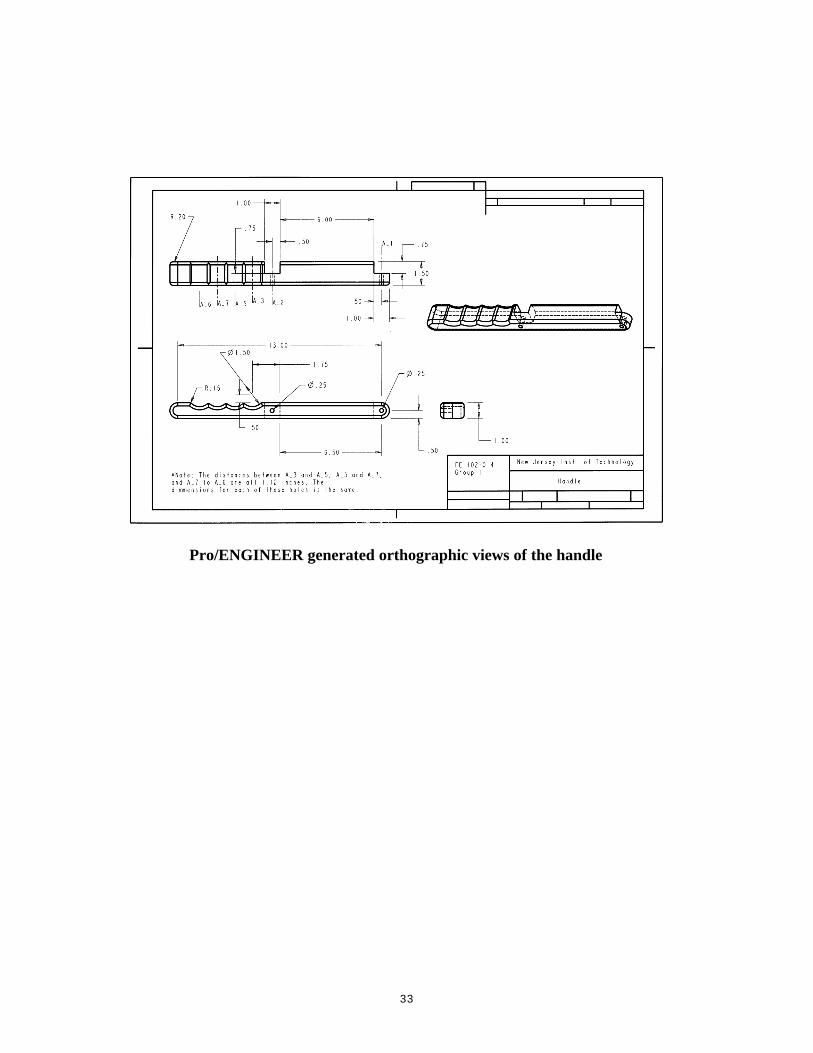
Pro/ENGINEER generated orthographic views of the handle
34
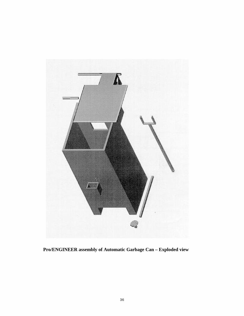
2. AUTOMATIC GARBAGE CAN
This garbage can has three main structures, they are:
• the levers at the base of the can,
• the hinge joint at the top of the can, and
• the rectangular body of the can.
The lever at the bottom of the can is mainly used as a mechanism to control the
vertical motion of the lid of the garbage can. The opening and closing motion of the
lid is caused by stepping on the lever which sends a vertical rod that pushes a hinge
connected to the lid and the upper portion of the garbage can to the open position. By
pressing the lever once will cause the lid to open, however this is where this garbage
can is different from other because once the foot is released, the vertical rod will
return to it's original position yet the lid will still remain open. The lid will remain
open until the lever is pressed again which sends the vertical rod to push the hinge to
the closed position.
Technical Specifications:
• The hinge that causes the motions of the opening and closing of the garbage can
lid will involve the lid opening from zero to one hundred degrees.
• The lever at the base of the can will be depressed from a thirty degrees angle to
zero degrees so that the vertical rod will be pushed up.
• The height of the garbage can will be 2.2 feet, the width will be 1 foot, the depth
is about 1.4 feet.
• The total volume is about 1000 cubic inches.
• Except some screws, this garbage bin is made entirely out of plastic.
• The net mass of the can is less than 20 pounds.
• All of the product components are 100% recyclable.

35
Pro/ENGINEER assembly of Automatic Garbage Can
36
Pro/ENGINEER assembly of Automatic Garbage Can – Exploded view
37
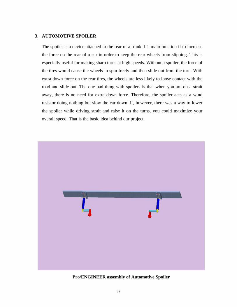
3. AUTOMOTIVE SPOILER
The spoiler is a device attached to the rear of a trunk. It's main function if to increase
the force on the rear of a car in order to keep the rear wheels from slipping. This is
especially useful for making sharp turns at high speeds. Without a spoiler, the force of
the tires would cause the wheels to spin freely and then slide out from the turn. With
extra down force on the rear tires, the wheels are less likely to loose contact with the
road and slide out. The one bad thing with spoilers is that when you are on a strait
away, there is no need for extra down force. Therefore, the spoiler acts as a wind
resistor doing nothing but slow the car down. If, however, there was a way to lower
the spoiler while driving strait and raise it on the turns, you could maximize your
overall speed. That is the basic idea behind our project.
Pro/ENGINEER assembly of Automotive Spoiler
38
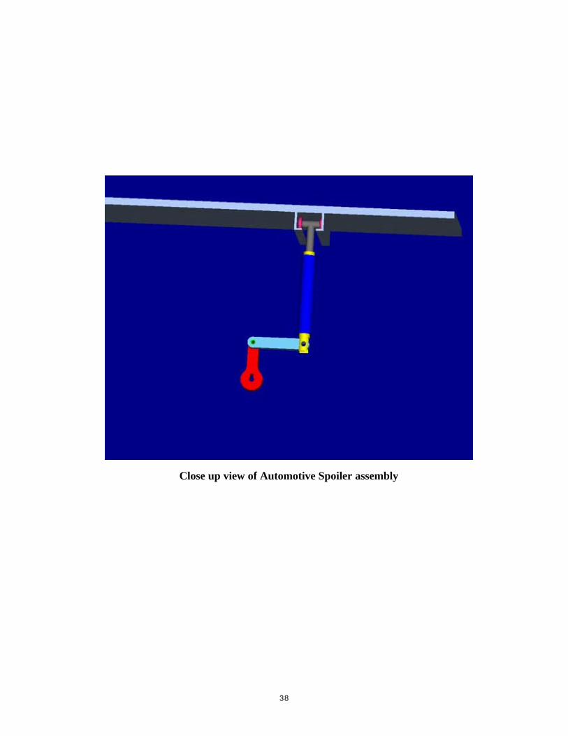
Close up view of Automotive Spoiler assembly