me1303-gas dynamics and jet propulsion.pdf
DESCRIPTION
aaTRANSCRIPT
ME1303 GAS DYNAMICS AND JET PROPULSION
COMPILED BY
CSELVAM
ASSISTANT PROFESSOR
DEPARTMENT OF MECHANICAL ENGINEERING
ME602 GAS DYNAMICS AND JET PROPULSION 3 1 0 100
OBJECTIVES
To Understand the basic difference between incompressible and compressible flow
To study the phenomenon of shock waves and its effect on flow
To gain basic knowledge about jet propulsion and Rocket Propulsion
1 COMPRESSIBLE FLOW ndash FUNDAMENTALS 8
Energy and momentum equations for compressible fluid flows various regions of flows reference velocities
stagnation state velocity of sound critical states Mach number critical Mach number types of waves Mach cone
Mach angle effect of Mach number on compressibility
2 FLOW THROUGH VARIABLE AREA DUCTS 9
Isentropic flow through variable area ducts T-s and h-s diagrams for nozzle and diffuser flows area ratio as a
function of Mach number mass flow rate through nozzles and diffusers effect of friction in flow through nozzles
3 FLOW THROUGH CONSTANT AREA DUCTS 10
Flow in constant area ducts with friction (Fanno flow) ndash Fanno curves and Fanno flow equation variation of flow
properties variation of Mach number with duct lengthIsothermal flow with friction in constant area ducts Flow in
constant area ducts with heat transfer (Rayleigh flow) Rayleigh line and Rayleigh flow equation variation of flow
properties maximum heat transfer
4 NORMAL SHOCK 8
Governing equations variation of flow parameters like static pressure static temperature density stagnation
pressure and entropy across the normal shock Prandtl - Meyer equation impossibility of shock in subsonic flows
flow in convergent and divergent nozzle with shock normal shock in Fanno and Rayleigh flows flow with oblique
shock (elementary treatment only)
5 PROPULSION 10
Aircraft propulsion ndash types of jet engines ndash energy flow through jet engines study of turbojet engine components ndash
diffuser compressor combustion chamber turbine and exhaust systems performance of turbo jet engines ndash thrust
thrust power propulsive and overall efficiencies thrust augmentation in turbo jet engine ram jet and pulse jet
engines Rocket propulsion ndash rocket engines thrust equation ndash effective jet velocity specific impulse ndash rocket engine
performance solid and liquid propellants comparison of different propulsion systems
TUTORIAL 15
TOTAL 60
Note (Use of approved gas tables is permitted in the University examination)
TEXT BOOKS
1 Yahya SM ―Fundamental of compressible flow New Age International (p) Ltd New Delhi 1996
2 PatrichH Oosthvizen William ECarscallen ―Compressible fluid flow McGraw-Hill 1997
REFERENCES
1 Cohen H Rogers REC and Sravanamutoo ―Gas turbine theory Addison Wesley Ltd 1987
2 Ganesan V ―Gas Turbines Tata McGraw-Hill New Delhi 1999
3 RathakrishnanE ―Gas Dynamics Prentice Hall of India New Delhi 2001
ME602 GAS DYNAMICS AND JET PROPULSION
UNIT I COMPRESSIBLE FLOW ndash FUNDAMENTALS
In physics fluid dynamics is a sub-discipline of fluid mechanics that deals with fluid
flowmdashthe natural science of fluids (liquids and gases) in motion It has several subdisciplines
itself including aerodynamics (the study of air and other gases in motion) and hydrodynamics
(the study of liquids in motion) Fluid dynamics has a wide range of applications including
calculating forces and moments on aircraft determining the mass flow rate of petroleum through
pipelines predicting weather patterns understanding nebulae in interstellar space and reportedly
modeling fission weapon detonation Some of its principles are even used in traffic engineering
where traffic is treated as a continuous fluid
Fluid dynamics offers a systematic structure that underlies these practical disciplines that
embraces empirical and semi-empirical laws derived from flow measurement and used to solve
practical problems The solution to a fluid dynamics problem typically involves calculating
various properties of the fluid such as velocity pressure density and temperature as functions
of space and time
Historically hydrodynamics meant something different than it does today Before the
twentieth century hydrodynamics was synonymous with fluid dynamics This is still reflected in
names of some fluid dynamics topics like magnetohydrodynamics and hydrodynamic stabilitymdash
both also applicable in as well as being applied to gasesa
The foundational axioms of fluid dynamics are the conservation laws specifically
conservation of mass conservation of linear momentum (also known as Newtons Second Law
of Motion) and conservation of energy (also known as First Law of Thermodynamics) These
are based on classical mechanics and are modified in quantum mechanics and general relativity
They are expressed using the Reynolds Transport Theorem
In addition to the above fluids are assumed to obey the continuum assumption Fluids are
composed of molecules that collide with one another and solid objects However the continuum
assumption considers fluids to be continuous rather than discrete Consequently properties such
as density pressure temperature and velocity are taken to be well-defined at infinitesimally
small points and are assumed to vary continuously from one point to another The fact that the
fluid is made up of discrete molecules is ignored
For fluids which are sufficiently dense to be a continuum do not contain ionized species
and have velocities small in relation to the speed of light the momentum equations for
Newtonian fluids are the Navier-Stokes equations which is a non-linear set of differential
equations that describes the flow of a fluid whose stress depends linearly on velocity gradients
and pressure The unsimplified equations do not have a general closed-form solution so they are
primarily of use in Computational Fluid Dynamics The equations can be simplified in a number
of ways all of which make them easier to solve Some of them allow appropriate fluid dynamics
problems to be solved in closed form
In addition to the mass momentum and energy conservation equations a
thermodynamical equation of state giving the pressure as a function of other thermodynamic
variables for the fluid is required to completely specify the problem An example of this would
be the perfect gas equation of state
where p is pressure ρ is density Ru is the gas constant M is the molar mass and T is
temperature
Compressible vs incompressible flow
All fluids are compressible to some extent that is changes in pressure or temperature will
result in changes in density However in many situations the changes in pressure and
temperature are sufficiently small that the changes in density are negligible In this case the flow
can be modeled as an incompressible flow Otherwise the more general compressible flow
equations must be used
Mathematically incompressibility is expressed by saying that the density ρ of a fluid
parcel does not change as it moves in the flow field ie
where D Dt is the substantial derivative which is the sum of local and convective
derivatives This additional constraint simplifies the governing equations especially in the case
when the fluid has a uniform density
For flow of gases to determine whether to use compressible or incompressible fluid dynamics
the Mach number of the flow is to be evaluated As a rough guide compressible effects can be
ignored at Mach numbers below approximately 03 For liquids whether the incompressible
assumption is valid depends on the fluid properties (specifically the critical pressure and
temperature of the fluid) and the flow conditions (how close to the critical pressure the actual
flow pressure becomes) Acoustic problems always require allowing compressibility since sound
waves are compression waves involving changes in pressure and density of the medium through
which they propagate
viscous vs inviscid flow
Viscous problems are those in which fluid friction has significant effects on the fluid motion
The Reynolds number which is a ratio between inertial and viscous forces can be used to
evaluate whether viscous or inviscid equations are appropriate to the problem
Stokes flow is flow at very low Reynolds numbers Reltlt1 such that inertial forces can be
neglected compared to viscous forces
On the contrary high Reynolds numbers indicate that the inertial forces are more significant than
the viscous (friction) forces Therefore we may assume the flow to be an inviscid flow an
approximation in which we neglect viscosity completely compared to inertial terms
This idea can work fairly well when the Reynolds number is high However certain problems
such as those involving solid boundaries may require that the viscosity be included Viscosity
often cannot be neglected near solid boundaries because the no-slip condition can generate a thin
region of large strain rate (known as Boundary layer) which enhances the effect of even a small
amount of viscosity and thus generating vorticity Therefore to calculate net forces on bodies
(such as wings) we should use viscous flow equations As illustrated by dAlemberts paradox a
body in an inviscid fluid will experience no drag force The standard equations of inviscid flow
are the Euler equations Another often used model especially in computational fluid dynamics is
to use the Euler equations away from the body and the boundary layer equations which
incorporates viscosity in a region close to the body
The Euler equations can be integrated along a streamline to get Bernoullis equation When the
flow is everywhere irrotational and inviscid Bernoullis equation can be used throughout the
flow field Such flows are called potential flows
Steady vs unsteady flow
When all the time derivatives of a flow field vanish the flow is considered to be a steady
flow Steady-state flow refers to the condition where the fluid properties at a point in the system
do not change over time Otherwise flow is called unsteady Whether a particular flow is steady
or unsteady can depend on the chosen frame of reference For instance laminar flow over a
sphere is steady in the frame of reference that is stationary with respect to the sphere In a frame
of reference that is stationary with respect to a background flow the flow is unsteady
Turbulent flows are unsteady by definition A turbulent flow can however be
statistically stationary
The random field U(xt) is statistically stationary if all statistics are invariant under a shift
in time
This roughly means that all statistical properties are constant in time Often the mean
field is the object of interest and this is constant too in a statistically stationary flow
Steady flows are often more tractable than otherwise similar unsteady flows The
governing equations of a steady problem have one dimension fewer (time) than the governing
equations of the same problem without taking advantage of the steadiness of the flow field
Laminar vs turbulent flow
Turbulence is flow characterized by recirculation eddies and apparent randomness Flow
in which turbulence is not exhibited is called laminar It should be noted however that the
presence of eddies or recirculation alone does not necessarily indicate turbulent flowmdashthese
phenomena may be present in laminar flow as well Mathematically turbulent flow is often
represented via a Reynolds decomposition in which the flow is broken down into the sum of an
average component and a perturbation component
It is believed that turbulent flows can be described well through the use of the NavierndashStokes
equations Direct numerical simulation (DNS) based on the NavierndashStokes equations makes it
possible to simulate turbulent flows at moderate Reynolds numbers Restrictions depend on the
power of the computer used and the efficiency of the solution algorithm The results of DNS
have been found to agree well with experimental data for some flows[4]
Most flows of interest have Reynolds numbers much too high for DNS to be a viable option[5]
given the state of computational power for the next few decades Any flight vehicle large enough
to carry a human (L gt 3 m) moving faster than 72 kmh (20 ms) is well beyond the limit of
DNS simulation (Re = 4 million) Transport aircraft wings (such as on an Airbus A300 or Boeing
747) have Reynolds numbers of 40 million (based on the wing chord) In order to solve these
real-life flow problems turbulence models will be a necessity for the foreseeable future
Reynolds-averaged NavierndashStokes equations (RANS) combined with turbulence modeling
provides a model of the effects of the turbulent flow Such a modeling mainly provides the
additional momentum transfer by the Reynolds stresses although the turbulence also enhances
the heat and mass transfer Another promising methodology is large eddy simulation (LES)
especially in the guise of detached eddy simulation (DES)mdashwhich is a combination of RANS
turbulence modeling and large eddy simulation
Newtonian vs non-Newtonian fluids
Sir Isaac Newton showed how stress and the rate of strain are very close to linearly related for
many familiar fluids such as water and air These Newtonian fluids are modeled by a coefficient
called viscosity which depends on the specific fluid
However some of the other materials such as emulsions and slurries and some visco-elastic
materials (eg blood some polymers) have more complicated non-Newtonian stress-strain
behaviours These materials include sticky liquids such as latex honey and lubricants which are
studied in the sub-discipline of rheology
Subsonic vs transonic supersonic and hypersonic flows
While many terrestrial flows (eg flow of water through a pipe) occur at low mach numbers
many flows of practical interest (eg in aerodynamics) occur at high fractions of the Mach
Number M=1 or in excess of it (supersonic flows) New phenomena occur at these Mach number
regimes (eg shock waves for supersonic flow transonic instability in a regime of flows with M
nearly equal to 1 non-equilibrium chemical behavior due to ionization in hypersonic flows) and
it is necessary to treat each of these flow regimes separately
Magnetohydrodynamics
Magnetohydrodynamics is the multi-disciplinary study of the flow of electrically conducting
fluids in electromagnetic fields Examples of such fluids include plasmas liquid metals and salt
water The fluid flow equations are solved simultaneously with Maxwells equations of
electromagnetism
Other approximations
There are a large number of other possible approximations to fluid dynamic problems Some of
the more commonly used are listed below
The Boussinesq approximation neglects variations in density except to calculate
buoyancy forces It is often used in free convection problems where density changes are
small
Lubrication theory and Hele-Shaw flow exploits the large aspect ratio of the domain to
show that certain terms in the equations are small and so can be neglected
Slender-body theory is a methodology used in Stokes flow problems to estimate the
force on or flow field around a long slender object in a viscous fluid
The shallow-water equations can be used to describe a layer of relatively inviscid fluid
with a free surface in which surface gradients are small
The Boussinesq equations are applicable to surface waves on thicker layers of fluid and
with steeper surface slopes
Darcys law is used for flow in porous media and works with variables averaged over
several pore-widths
In rotating systems the quasi-geostrophic approximation assumes an almost perfect
balance between pressure gradients and the Coriolis force It is useful in the study of
atmospheric dynamics
Terminology in incompressible fluid dynamics
The concepts of total pressure and dynamic pressure arise from Bernoullis equation and are
significant in the study of all fluid flows (These two pressures are not pressures in the usual
sensemdashthey cannot be measured using an aneroid Bourdon tube or mercury column) To avoid
potential ambiguity when referring to pressure in fluid dynamics many authors use the term
static pressure to distinguish it from total pressure and dynamic pressure Static pressure is
identical to pressure and can be identified for every point in a fluid flow field
In Aerodynamics LJ Clancy writes[6]
To distinguish it from the total and dynamic pressures
the actual pressure of the fluid which is associated not with its motion but with its state is often
referred to as the static pressure but where the term pressure alone is used it refers to this static
pressure
A point in a fluid flow where the flow has come to rest (ie speed is equal to zero adjacent to
some solid body immersed in the fluid flow) is of special significance It is of such importance
that it is given a special namemdasha stagnation point The static pressure at the stagnation point is
of special significance and is given its own namemdashstagnation pressure In incompressible flows
the stagnation pressure at a stagnation point is equal to the total pressure throughout the flow
field
Terminology in compressible fluid dynamics
In a compressible fluid such as air the temperature and density are essential when determining
the state of the fluid In addition to the concept of total pressure (also known as stagnation
pressure) the concepts of total (or stagnation) temperature and total (or stagnation) density are
also essential in any study of compressible fluid flows To avoid potential ambiguity when
referring to temperature and density many authors use the terms static temperature and static
density Static temperature is identical to temperature and static density is identical to density
and both can be identified for every point in a fluid flow field
The temperature and density at a stagnation point are called stagnation temperature and
stagnation density
A similar approach is also taken with the thermodynamic properties of compressible fluids
Many authors use the terms total (or stagnation) enthalpy and total (or stagnation) entropy The
terms static enthalpy and static entropy appear to be less common but where they are used they
mean nothing more than enthalpy and entropy respectively and the prefix static is being used
to avoid ambiguity with their total or stagnation counterparts Because the total flow
conditions are defined by isentropically bringing the fluid to rest the total (or stagnation) entropy
is by definition always equal to the static entropy
The Mach number is commonly used both with objects traveling at high speed in a fluid and
with high-speed fluid flows inside channels such as nozzles diffusers or wind tunnels As it is
defined as a ratio of two speeds it is a dimensionless number At Standard Sea Level conditions
(corresponding to a temperature of 15 degrees Celsius) the speed of sound is 3403 ms[3]
(1225
kmh or 7612 mph or 6615 knots or 1116 fts) in the Earths atmosphere The speed
represented by Mach 1 is not a constant for example it is mostly dependent on temperature and
atmospheric composition and largely independent of pressure In the stratosphere where the
temperatures are constant it does not vary with altitude even though the air pressure changes
significantly with altitude
Since the speed of sound increases as the temperature increases the actual speed of an object
traveling at Mach 1 will depend on the fluid temperature around it Mach number is useful
because the fluid behaves in a similar way at the same Mach number So an aircraft traveling at
Mach 1 at 20degC or 68degF will experience shock waves in much the same manner as when it is
traveling at Mach 1 at 11000 m (36000 ft) at -50degC or -58F even though it is traveling at only
86 of its speed at higher temperature like 20degC or 68degF
High-speed flow around objects
Flight can be roughly classified in six categories
Regime Subsonic Transonic Sonic Supersonic Hypersonic High-
hypersonic
Mach lt075 075ndash12 10 12ndash50 50ndash100 gt100
For comparison the required speed for low Earth orbit is approximately 75 kms = Mach 254 in
air at high altitudes The speed of light in a vacuum corresponds to a Mach number of
approximately 881000 (relative to air at sea level)
At transonic speeds the flow field around the object includes both sub- and supersonic parts The
transonic period begins when first zones of Mgt1 flow appear around the object In case of an
airfoil (such as an aircrafts wing) this typically happens above the wing Supersonic flow can
decelerate back to subsonic only in a normal shock this typically happens before the trailing
edge (Fig1a)
As the speed increases the zone of Mgt1 flow increases towards both leading and trailing edges
As M=1 is reached and passed the normal shock reaches the trailing edge and becomes a weak
oblique shock the flow decelerates over the shock but remains supersonic A normal shock is
created ahead of the object and the only subsonic zone in the flow field is a small area around
the objects leading edge (Fig1b)
(a) (b)
Fig 1 Mach number in transonic airflow around an airfoil Mlt1 (a) and Mgt1 (b)
When an aircraft exceeds Mach 1 (ie the sound barrier) a large pressure difference is created
just in front of the aircraft This abrupt pressure difference called a shock wave spreads
backward and outward from the aircraft in a cone shape (a so-called Mach cone) It is this shock
wave that causes the sonic boom heard as a fast moving aircraft travels overhead A person
inside the aircraft will not hear this The higher the speed the more narrow the cone at just over
M=1 it is hardly a cone at all but closer to a slightly concave plane
At fully supersonic speed the shock wave starts to take its cone shape and flow is either
completely supersonic or (in case of a blunt object) only a very small subsonic flow area
remains between the objects nose and the shock wave it creates ahead of itself (In the case of a
sharp object there is no air between the nose and the shock wave the shock wave starts from the
nose)
As the Mach number increases so does the strength of the shock wave and the Mach cone
becomes increasingly narrow As the fluid flow crosses the shock wave its speed is reduced and
temperature pressure and density increase The stronger the shock the greater the changes At
high enough Mach numbers the temperature increases so much over the shock that ionization and
dissociation of gas molecules behind the shock wave begin Such flows are called hypersonic
It is clear that any object traveling at hypersonic speeds will likewise be exposed to the same
extreme temperatures as the gas behind the nose shock wave and hence choice of heat-resistant
materials becomes important
High-speed flow in a channel
As a flow in a channel crosses M=1 becomes supersonic one significant change takes place The
conservation of mass flow rate leads one to expect that contracting the flow channel would
increase the flow speed (ie making the channel narrower results in faster air flow) and at
subsonic speeds this holds true However once the flow becomes supersonic the relationship of
flow area and speed is reversed expanding the channel actually increases the speed
The obvious result is that in order to accelerate a flow to supersonic one needs a convergent-
divergent nozzle where the converging section accelerates the flow to M=1 sonic speeds and
the diverging section continues the acceleration Such nozzles are called de Laval nozzles and in
extreme cases they are able to reach incredible hypersonic speeds (Mach 13 at 20degC)
An aircraft Machmeter or electronic flight information system (EFIS) can display Mach number
derived from stagnation pressure (pitot tube) and static pressure
Critical Mach number
In aerodynamics the critical Mach number (Mcr) of an aircraft is the lowest Mach number at
which the airflow over a small region of the wing reaches the speed of sound[1]
For all aircraft in flight the airflow around the aircraft is not exactly the same as the airspeed of
the aircraft due to the airflow speeding up and slowing down to travel around the aircraft
structure At the Critical Mach number local airflow in some areas near the airframe reaches the
speed of sound even though the aircraft itself has an airspeed lower than Mach 10 This creates
a weak shock wave At speeds faster than the Critical Mach number
drag coefficient increases suddenly causing dramatically increased drag
in aircraft not designed for transonic or supersonic speeds changes to the airflow over the
flight control surfaces lead to deterioration in control of the aircraft
In aircraft not designed to fly at the Critical Mach number shock waves in the flow over the
wing and tailplane were sufficient to stall the wing make control surfaces ineffective or lead to
loss of control such as Mach tuck The phenomena associated with problems at the Critical Mach
number became known as compressibility Compressibility led to a number of accidents
involving high-speed military and experimental aircraft in the 1930s and 1940s
Although unknown at the time compressibility was the cause of the phenomenon known as the
sound barrier Subsonic aircraft such as the Supermarine Spitfire BF 109 P-51 Mustang Gloster
Meteor Me 262 P-80 have relatively thick unswept wings and are incapable of reaching Mach
10 In 1947 Chuck Yeager flew the Bell X-1 to Mach 10 and beyond and the sound barrier
was finally broken
Early transonic military aircraft such as the Hawker Hunter and F-86 Sabre were designed to fly
satisfactorily faster than their Critical Mach number They did not possess sufficient engine
thrust to reach Mach 10 in level flight but could be dived to Mach 10 and beyond and remain
controllable Modern passenger-carrying jet aircraft such as Airbus and Boeing aircraft have
Maximum Operating Mach numbers slower than Mach 10
Supersonic aircraft such as Concorde the English Electric Lightning Lockheed F-104 Dassault
Mirage III and MiG 21 are designed to exceed Mach 10 in level flight They have very thin
wings Their Critical Mach numbers are higher than those of subsonic and transonic aircraft but
less than Mach 10
The actual Critical Mach number varies from wing to wing In general a thicker wing will have a
lower Critical Mach number because a thicker wing accelerates the airflow to a faster speed than
a thinner one For instance the fairly thick wing on the P-38 Lightning led to a Critical Mach
number of about 69 a speed it could reach with some ease in dives which led to a number of
crashes The much thinner wing on the Supermarine Spitfire caused this aircraft to have a
Critical Mach number of about 089
Effects of Mach number and compressibility
We study the effects of Mach number and compressibility on strain-rate and vorticity dynamics
in decaying isotropic turbulence employing direct numerical simulations Since local Mach
number and dilatation are two direct indicators of compressibility of a fluid element we use
these quantities as conditioning parameters to examine the various aspects of turbulence
dynamics Several interesting observations along with the underlying physics pertaining to the
inertial (vortex stretching and self-straining) and pressure (pressure Hessian and baroclinic)
terms in the budget of strain-rate and vorticity dynamics will be presented in the talk The
contrasting nature of these physical effects in expanding vs contracting and supersonic vs
subsonic fluid elements will be highlighted
UNIT-II amp III FLOW THROUGH CONSTANT amp VARIABLE AREA DUCTS
Rayleigh Flow
Rayleigh flow refers to diabatic flow through a constant area duct where the effect
of heat addition or rejection is considered Compressibility effects often come into consideration
although the Rayleigh flow model certainly also applies to incompressible flow For this model
the duct area remains constant and no mass is added within the duct Therefore unlike Fanno
flow the stagnation temperature is a variable The heat addition causes a decrease in stagnation
pressure which is known as the Rayleigh effect and is critical in the design of combustion
systems Heat addition will cause both supersonic and subsonic Mach numbers to approach
Mach 1 resulting in choked flow Conversely heat rejection decreases a subsonic Mach number
and increases a supersonic Mach number along the duct It can be shown that for calorically
perfect flows the maximum entropy occurs at M = 1 Rayleigh flow is named after John Strutt
3rd Baron Rayleigh
Fanno Flow
Fanno flow refers to adiabatic through a constant area duct where the effect of
friction is considered Compressibilityflow effects often come into consideration although the
Fanno flow model certainly also applies to incompressible flow For this model the duct area
remains constant the flow is assumed to be steady and one-dimensional and no mass is added
within the duct The Fanno flow model is considered an irreversible process due to viscous
effects The viscous friction causes the flow properties to change along the duct The frictional
effect is modeled as a shear stress at the wall acting on the fluid with uniform properties over any
cross section of the duct
For a flow with an upstream Mach number greater than 10 in a sufficiently long enough
duct deceleration occurs and the flow can become choked On the other hand for a flow with an
upstream Mach number less than 10 acceleration occurs and the flow can become choked in a
sufficiently long duct It can be shown that for flow of calorically per The Fanno flow model
begins with a differential equation that relates the change in Mach number with respect to the
length of the duct dMdx Other terms in the differential equation are the heat capacity ratio γ
the Fanning friction factor f and the hydraulic diameter Dh
Variation of Fluid Properties
Equations of fluid dynamics
The foundational axioms of fluid dynamics are the conservation laws specifically conservation
of mass conservation of linear momentum (also known as Newtons Second Law of Motion)
and conservation of energy (also known as First Law of Thermodynamics) These are based on
classical mechanics and are modified in quantum mechanics and general relativity They are
expressed using the Reynolds Transport Theorem
In addition to the above fluids are assumed to obey the continuum assumption Fluids are
composed of molecules that collide with one another and solid objects However the continuum
assumption considers fluids to be continuous rather than discrete Consequently properties such
as density pressure temperature and velocity are taken to be well-defined at infinitesimally
small points and are assumed to vary continuously from one point to another The fact that the
fluid is made up of discrete molecules is ignored
For fluids which are sufficiently dense to be a continuum do not contain ionized species and
have velocities small in relation to the speed of light the momentum equations for Newtonian
fluids are the Navier-Stokes equations which is a non-linear set of differential equations that
describes the flow of a fluid whose stress depends linearly on velocity gradients and pressure
The unsimplified equations do not have a general closed-form solution so they are primarily of
use in Computational Fluid Dynamics The equations can be simplified in a number of ways all
of which make them easier to solve Some of them allow appropriate fluid dynamics problems to
be solved in closed form
In addition to the mass momentum and energy conservation equations a thermodynamical
equation of state giving the pressure as a function of other thermodynamic variables for the fluid
is required to completely specify the problem An example of this would be the perfect gas
equation of state
where p is pressure ρ is density Ru is the gas constant M is the molar mass and T is temperature
Compressible vs incompressible flow
All fluids are compressible to some extent that is changes in pressure or temperature will result
in changes in density However in many situations the changes in pressure and temperature are
sufficiently small that the changes in density are negligible In this case the flow can be modeled
as an incompressible flow Otherwise the more general compressible flow equations must be
used
Mathematically incompressibility is expressed by saying that the density ρ of a fluid parcel does
not change as it moves in the flow field ie
where D Dt is the substantial derivative which is the sum of local and convective derivatives
This additional constraint simplifies the governing equations especially in the case when the
fluid has a uniform density
For flow of gases to determine whether to use compressible or incompressible fluid dynamics
the Mach number of the flow is to be evaluated As a rough guide compressible effects can be
ignored at Mach numbers below approximately 03 For liquids whether the incompressible
assumption is valid depends on the fluid properties (specifically the critical pressure and
temperature of the fluid) and the flow conditions (how close to the critical pressure the actual
flow pressure becomes) Acoustic problems always require allowing compressibility since sound
waves are compression waves involving changes in pressure and density of the medium through
which they propagate
Viscous vs inviscid flow
Viscous problems are those in which fluid friction has significant effects on the fluid motion
The Reynolds number which is a ratio between inertial and viscous forces can be used to
evaluate whether viscous or inviscid equations are appropriate to the problem
Stokes flow is flow at very low Reynolds numbers Reltlt1 such that inertial forces can be
neglected compared to viscous forces
On the contrary high Reynolds numbers indicate that the inertial forces are more significant than
the viscous (friction) forces Therefore we may assume the flow to be an inviscid flow an
approximation in which we neglect viscosity completely compared to inertial terms
This idea can work fairly well when the Reynolds number is high However certain problems
such as those involving solid boundaries may require that the viscosity be included Viscosity
often cannot be neglected near solid boundaries because the no-slip condition can generate a thin
region of large strain rate (known as Boundary layer) which enhances the effect of even a small
amount of viscosity and thus generating vorticity Therefore to calculate net forces on bodies
(such as wings) we should use viscous flow equations As illustrated by dAlemberts paradox a
body in an inviscid fluid will experience no drag force The standard equations of inviscid flow
are the Euler equations Another often used model especially in computational fluid dynamics is
to use the Euler equations away from the body and the boundary layer equations which
incorporates viscosity in a region close to the body
The Euler equations can be integrated along a streamline to get Bernoullis equation When the
flow is everywhere irrotational and inviscid Bernoullis equation can be used throughout the
flow field Such flows are called potential flows
Steady vs unsteady flow
Hydrodynamics simulation of the RayleighndashTaylor instability
When all the time derivatives of a flow field vanish the flow is considered to be a steady flow
Steady-state flow refers to the condition where the fluid properties at a point in the system do not
change over time Otherwise flow is called unsteady Whether a particular flow is steady or
unsteady can depend on the chosen frame of reference For instance laminar flow over a sphere
is steady in the frame of reference that is stationary with respect to the sphere In a frame of
reference that is stationary with respect to a background flow the flow is unsteady
Turbulent flows are unsteady by definition A turbulent flow can however be statistically
stationary According to Pope
The random field U(xt) is statistically stationary if all statistics are invariant under a shift in
time
This roughly means that all statistical properties are constant in time Often the mean field is the
object of interest and this is constant too in a statistically stationary flow
Steady flows are often more tractable than otherwise similar unsteady flows The governing
equations of a steady problem have one dimension fewer (time) than the governing equations of
the same problem without taking advantage of the steadiness of the flow field
Laminar vs turbulent flow
Turbulence is flow characterized by recirculation eddies and apparent randomness Flow in
which turbulence is not exhibited is called laminar It should be noted however that the
presence of eddies or recirculation alone does not necessarily indicate turbulent flowmdashthese
phenomena may be present in laminar flow as well Mathematically turbulent flow is often
represented via a Reynolds decomposition in which the flow is broken down into the sum of an
average component and a perturbation component
It is believed that turbulent flows can be described well through the use of the NavierndashStokes
equations Direct numerical simulation (DNS) based on the NavierndashStokes equations makes it
possible to simulate turbulent flows at moderate Reynolds numbers Restrictions depend on the
power of the computer used and the efficiency of the solution algorithm The results of DNS
have been found to agree well with experimental data for some flows
Most flows of interest have Reynolds numbers much too high for DNS to be a viable option
given the state of computational power for the next few decades Any flight vehicle large enough
to carry a human (L gt 3 m) moving faster than 72 kmh (20 ms) is well beyond the limit of
DNS simulation (Re = 4 million) Transport aircraft wings (such as on an Airbus A300 or Boeing
747) have Reynolds numbers of 40 million (based on the wing chord) In order to solve these
real-life flow problems turbulence models will be a necessity for the foreseeable future
Reynolds-averaged NavierndashStokes equations (RANS) combined with turbulence modeling
provides a model of the effects of the turbulent flow Such a modeling mainly provides the
additional momentum transfer by the Reynolds stresses although the turbulence also enhances
the heat and mass transfer Another promising methodology is large eddy simulation (LES)
especially in the guise of detached eddy simulation (DES)mdashwhich is a combination of RANS
turbulence modeling and large eddy simulation
Newtonian vs non-Newtonian fluids
Sir Isaac Newton showed how stress and the rate of strain are very close to linearly related for
many familiar fluids such as water and air These Newtonian fluids are modeled by a coefficient
called viscosity which depends on the specific fluid
However some of the other materials such as emulsions and slurries and some visco-elastic
materials (eg blood some polymers) have more complicated non-Newtonian stress-strain
behaviours These materials include sticky liquids such as latex honey and lubricants which are
studied in the sub-discipline of rheology
Subsonic vs transonic supersonic and hypersonic flows
While many terrestrial flows (eg flow of water through a pipe) occur at low mach numbers
many flows of practical interest (eg in aerodynamics) occur at high fractions of the Mach
Number M=1 or in excess of it (supersonic flows) New phenomena occur at these Mach number
regimes (eg shock waves for supersonic flow transonic instability in a regime of flows with M
nearly equal to 1 non-equilibrium chemical behavior due to ionization in hypersonic flows) and
it is necessary to treat each of these flow regimes separately
Magnetohydrodynamics
Magnetohydrodynamics is the multi-disciplinary study of the flow of electrically conducting
fluids in electromagnetic fields Examples of such fluids include plasmas liquid metals and salt
water The fluid flow equations are solved simultaneously with Maxwells equations of
electromagnetism
Use of Tables and Charts
Fanno Flow
Fanno flow refers to adiabatic flow through a constant area duct where the effect The equation
above can be used to plot the Fanno line
Rayleigh flow
Rayleigh flow refers to adiabatic flow through a constant area duct where the effect Therefore
unlike Fanno flow the stagnation
UNIT IV NORMAL SHOCK
A shock wave (also called shock front or simply shock) is a type of propagating disturbance
Like an ordinary wave it carries energy and can propagate through a medium (solid liquid gas
or plasma) or in some cases in the absence of a material medium through a field such as the
electromagnetic field Shock waves are characterized by an abrupt nearly discontinuous change
in the characteristics of the medium[1]
Across a shock there is always an extremely rapid rise in
pressure temperature and density of the flow In supersonic flows expansion is achieved
through an expansion fan A shock wave travels through most media at a higher speed than an
ordinary wave
Unlike solitons (another kind of nonlinear wave) the energy of a shock wave dissipates
relatively quickly with distance Also the accompanying expansion wave approaches and
eventually merges with the shock wave partially cancelling it out Thus the sonic boom
associated with the passage of a supersonic aircraft is the sound wave resulting from the
degradation and merging of the shock wave and the expansion wave produced by the aircraft
When a shock wave passes through matter the total energy is preserved but the energy which
can be extracted as work decreases and entropy increases This for example creates additional
drag force on aircraft with shocks
Shock waves can be
Normal at 90deg (perpendicular) to the shock mediums flow direction
Oblique at an angle to the direction of flow
Bow Occurs upstream of the front (bow) of a blunt object when the upstream velocity
exceeds Mach 1
Some other terms
Shock Front an alternative name for the shock wave itself
Contact Front in a shock wave caused by a driver gas (for example the impact of a
high explosive on the surrounding air) the boundary between the driver (explosive
products) and the driven (air) gases The Contact Front trails the Shock Front
In supersonic flows
Pressure-time diagram at an external observation point for the case of a supersonic object
propagating past the observer The leading edge of the object causes a shock (left in red) and the
trailing edge of the object causes an expansion (right in blue)
When an object (or disturbance) moves faster than the information about it can be propagated
into the surrounding fluid fluid near the disturbance cannot react or get out of the way before
the disturbance arrives In a shock wave the properties of the fluid (density pressure
temperature velocity Mach number) change almost instantaneously Measurements of the
thickness of shock waves have resulted in values approximately one order of magnitude greater
than the mean free path of the gas investigated
Shock waves form when the speed of a gas changes by more than the speed of sound[2]
At the
region where this occurs sound waves traveling against the flow reach a point where they cannot
travel any further upstream and the pressure progressively builds in that region and a high
pressure shock wave rapidly forms
Shock waves are not conventional sound waves a shock wave takes the form of a very sharp
change in the gas properties on the order of a few mean free paths (roughly micro-meters at
atmospheric conditions) in thickness Shock waves in air are heard as a loud crack or snap
noise Over longer distances a shock wave can change from a nonlinear wave into a linear wave
degenerating into a conventional sound wave as it heats the air and loses energy The sound
wave is heard as the familiar thud or thump of a sonic boom commonly created by the
supersonic flight of aircraft
The shock wave is one of several different ways in which a gas in a supersonic flow can be
compressed Some other methods are isentropic compressions including Prandtl-Meyer
compressions The method of compression of a gas results in different temperatures and densities
for a given pressure ratio which can be analytically calculated for a non-reacting gas A shock
wave compression results in a loss of total pressure meaning that it is a less efficient method of
compressing gases for some purposes for instance in the intake of a scramjet The appearance of
pressure-drag on supersonic aircraft is mostly due to the effect of shock compression on the flow
Due to nonlinear steepening
Shock waves can form due to steepening of ordinary waves The best-known example of this
phenomenon is ocean waves that form breakers on the shore In shallow water the speed of
surface waves is dependent on the depth of the water An incoming ocean wave has a slightly
higher wave speed near the crest of each wave than near the troughs between waves because the
wave height is not infinitesimal compared to the depth of the water The crests overtake the
troughs until the leading edge of the wave forms a vertical face and spills over to form a
turbulent shock (a breaker) that dissipates the waves energy as sound and heat
Similar phenomena affect strong sound waves in gas or plasma due to the dependence of the
sound speed on temperature and pressure Strong waves heat the medium near each pressure
front due to adiabatic compression of the air itself so that high pressure fronts outrun the
corresponding pressure troughs While shock formation by this process does not normally
happen to sound waves in Earths atmosphere it is thought to be one mechanism by which the
solar chromosphere and corona are heated via waves that propagate up from the solar interior
Analogies
A shock wave may be described as the furthest point upstream of a moving object which
knows about the approach of the object In this description the shock wave position is defined
as the boundary between the zone having no information about the shock-driving event and the
zone aware of the shock-driving event analogous with the light cone described in the theory of
special relativity
To get a shock wave something has to be travelling faster than the local speed of sound In that
case some parts of the air around the aircraft are travelling at exactly the speed of sound with the
aircraft so that the sound waves leaving the aircraft pile up on each other similar to a tailback on
a road and a shock wave forms the pressure increases and then spreads out sideways Because
of this amplification effect a shock wave is very intense more like an explosion when heard (not
coincidentally since explosions create shock waves)
Analogous phenomena are known outside fluid mechanics For example particles accelerated
beyond the speed of light in a refractive medium (where the speed of light is less than that in a
vacuum such as water) create visible shock effects a phenomenon known as Cherenkov
radiation
Examples
Below are a number of examples of shock waves broadly grouped with similar shock
phenomena
Shock wave propagating into a stationary medium ahead of the fireball of an explosion The
shock is made visible by the shadow effect (Trinity explosion)
Moving shock
Usually consists of a shockwave propagating into a stationary medium
In this case the gas ahead of the shock is stationary (in the laboratory frame) and the gas
behind the shock is supersonic in the laboratory frame The shock propagates with a wave
front which is normal (at right angles) to the direction of flow The speed of the shock is
a function of the original pressure ratio between the two bodies of gas
Moving shocks are usually generated by the interaction of two bodies of gas at different
pressure with a shock wave propagating into the lower pressure gas and an expansion
wave propagating into the higher pressure gas
Examples Balloon bursting Shock tube shock wave from explosion
Detonation wave
Main article Detonation
A detonation wave is essentially a shock supported by a trailing exothermic reaction It
involves a wave traveling through a highly combustible or chemically unstable medium
such as an oxygen-methane mixture or a high explosive The chemical reaction of the
medium occurs following the shock wave and the chemical energy of the reaction drives
the wave forward
A detonation wave follows slightly different rules from an ordinary shock since it is
driven by the chemical reaction occurring behind the shock wave front In the simplest
theory for detonations an unsupported self-propagating detonation wave proceeds at the
Chapman-Jouguet velocity A detonation will also cause a shock of type 1 above to
propagate into the surrounding air due to the overpressure induced by the explosion
When a shockwave is created by high explosives such as TNT (which has a detonation
velocity of 6900 ms) it will always travel at high supersonic velocity from its point of
origin
Shadowgraph of the detached shock on a bullet in supersonic flight published by Ernst Mach in
1887
Detached shock
These shocks are curved and form a small distance in front of the body Directly in front
of the body they stand at 90 degrees to the oncoming flow and then curve around the
body Detached shocks allow the same type of analytic calculations as for the attached
shock for the flow near the shock They are a topic of continuing interest because the
rules governing the shocks distance ahead of the blunt body are complicated and are a
function of the bodys shape Additionally the shock standoff distance varies drastically
with the temperature for a non-ideal gas causing large differences in the heat transfer to
the thermal protection system of the vehicle See the extended discussion on this topic at
Atmospheric reentry These follow the strong-shock solutions of the analytic equations
meaning that for some oblique shocks very close to the deflection angle limit the
downstream Mach number is subsonic See also bow shock or oblique shock
Such a shock occurs when the maximum deflection angle is exceeded A detached shock
is commonly seen on blunt bodies but may also be seen on sharp bodies at low Mach
numbers
Examples Space return vehicles (Apollo Space shuttle) bullets the boundary (Bow
shock) of a magnetosphere The name bow shock comes from the example of a bow
wave the detached shock formed at the bow (front) of a ship or boat moving through
water whose slow surface wave speed is easily exceeded (see ocean surface wave)
Attached shock
These shocks appear as attached to the tip of a sharp body moving at supersonic speeds
Examples Supersonic wedges and cones with small apex angles
The attached shock wave is a classic structure in aerodynamics because for a perfect gas
and inviscid flow field an analytic solution is available such that the pressure ratio
temperature ratio angle of the wedge and the downstream Mach number can all be
calculated knowing the upstream Mach number and the shock angle Smaller shock
angles are associated with higher upstream Mach numbers and the special case where the
shock wave is at 90 degrees to the oncoming flow (Normal shock) is associated with a
Mach number of one These follow the weak-shock solutions of the analytic equations
Recompression shock
These shocks appear when the flow over a transonic body is decelerated to subsonic
speeds
Examples Transonic wings turbines
Where the flow over the suction side of a transonic wing is accelerated to a supersonic
speed the resulting re-compression can be by either Prandtl-Meyer compression or by the
formation of a normal shock This shock is of particular interest to makers of transonic
devices because it can cause separation of the boundary layer at the point where it
touches the transonic profile This can then lead to full separation and stall on the profile
higher drag or shock-buffet a condition where the separation and the shock interact in a
resonance condition causing resonating loads on the underlying structure
Shock in a pipe flow
This shock appears when supersonic flow in a pipe is decelerated
Examples Supersonic ramjet scramjet needle valve
In this case the gas ahead of the shock is supersonic (in the laboratory frame) and the gas
behind the shock system is either supersonic (oblique shocks) or subsonic (a normal
shock) (Although for some oblique shocks very close to the deflection angle limit the
downstream Mach number is subsonic) The shock is the result of the deceleration of the
gas by a converging duct or by the growth of the boundary layer on the wall of a parallel
duct
Shock waves in rapid granular flows
Shock waves can also occur in rapid flows of dense granular materials down inclined channels or
slopes Strong shocks in rapid dense granular flows can be studied theoretically and analyzed to
compare with experimental data Consider a configuration in which the rapidly moving material
down the chute impinges on an obstruction wall erected perpendicular at the end of a long and
steep channel Impact leads to a sudden change in the flow regime from a fast moving
supercritical thin layer to a stagnant thick heap This flow configuration is particularly interesting
because it is analogous to some hydraulic and aerodynamic situations associated with flow
regime changes from supercritical to subcritical flows Such study is important in estimating
impact pressures exerted by avalanches and granular flows on defense structures or infrastructure
along the channel and in the run-out zones and to study the complex flow dynamics around the
obstacles and in depositions when the mass comes suddenly to a standstill
Shock waves in astrophysics
Main article Shock waves in astrophysics
Astrophysical environments feature many different types of shock waves Some common
examples are supernovae shock waves or blast waves traveling through the interstellar medium
the bow shock caused by the Earths magnetic field colliding with the solar wind and shock
waves caused by galaxies colliding with each other Another interesting type of shock in
astrophysics is the quasi-steady reverse shock or termination shock that terminates the ultra
relativistic wind from young pulsars
UNIT V PROPULSION
Centuries ago in 100 AD Hero a Greek philosopher and mathematician demonstrated jet
power in a machine called an aeolipile A heated water filled steel ball with nozzles spun as
steam escaped
Over the course of the past half a century jet-powered flight has vastly changed the way we all
live However the basic principle of jet propulsion is neither new nor complicated
Centuries ago in 100 AD Hero a Greek philosopher and mathematician demonstrated jet
power in a machine called an aeolipile A heated water filled steel ball with nozzles spun as
steam escaped Why The principle behind this phenomenon was not fully understood until 1690
AD when Sir Isaac Newton in England formulated the principle of Heros jet propulsion
aeolipile in scientific terms His Third Law of Motion stated Every action produces a reaction
equal in force and opposite in direction
The jet engine of today operates according to this same basic principle Jet engines contain three
common components the compressor the combustor and the turbine To this basic engine
other components may be added including
A nozzle to recover and direct the gas energy and possibly divert the thrust for vertical
takeoff and landing as well as changing direction of aircraft flight
An afterburneror augmentor a long tailpipe behind the turbine into which additional
fuel is sprayed and burned to provide additional thrust
A thrust reverser which blocks the gas rushing toward the rear of the engine thus
forcing the gases forward to provide additional braking of aircraft
A fan in front of the compressor to increase thrust and reduce fuel consumption
An additional turbine that can be utilized to drive a propeller or helicopter rotor
Pressure and Velocity Air is normally thought of in relation to its
temperature pr e s s u re and v o lu m e Within a gas turbine engine the air is put into motion
so now an o t h er factor must be considered v e lo c i t y C o ns i d e r a co n s t an t a i r f l o w
t h ro u gh a duct As long as the duct crosssectional area r em a i ns u n ch an ged air will
co n t i nu e to flow at the same rate ( d i s r ega rd f r i c t i on a l loss) If the crosssectional area
of the duct should become smaller (convergent) the a i r f l o w must i n c r ea s e v e l o c i t y
if it is to con t in u e to flow the same number of pounds per second of a i r f l ow (Bernoullis
Principle) In order to obtain the n ece ss a r y v e lo c i t y energy to a c co mpl i s h this the air
must give up some p r e s su r e and temperature energy (law of conservation of en e r g y)
The net result of flow t h ro u gh this restriction would be a decrease in pressure and
temperature and an i n c r ea s e in v e lo c i t y The opposite would be true if air were to
flow from a s m a l l e r into a larger duct ( d iv e rgen t area) v e l o c i t y would then d ec r eas e
and p r e s su r e and t em p er a tu r e w ou ld in c r eas e The t h ro a t o f an au t om obi l e
c a r b ur e to r i s a good ex ampl e of the effect of airflow t h r o u gh a restriction ( v en tu r i )
even on the h o t t es t day the center portion of the ca r b u re to r feels cool Co nv e r gen t and
d iv e r gen t areas are used t h r ou gh ou t a gas t u r b in e engine to control p r e s s u r e and
v e lo c i t y of the a i r ga s stream as it flows through the engine
jet engine is a reaction engine that discharges a fast moving jet of fluid to generate thrust by jet
propulsion and in accordance with Newtons laws of motion This broad definition of jet engines
includes turbojets turbofans rockets ramjets pulse jets and pump-jets In general most jet
engines are internal combustion engines[1]
but non-combusting forms also exist
In common parlance the term jet engine loosely refers to an internal combustion airbreathing jet
engine (a duct engine) These typically consist of an engine with a rotary (rotating) air
compressor powered by a turbine (Brayton cycle) with the leftover power providing thrust via
a propelling nozzle These types of jet engines are primarily used by jet aircraft for long distance
travel Early jet aircraft used turbojet engines which were relatively inefficient for subsonic
flight Modern subsonic jet aircraft usually use high-bypass turbofan engines which give high
speeds as well as (over long distances) better fuel efficiency than many other forms of transport
History
Jet engines can be dated back to the invention of the aeolipile before the first century AD This
device used steam power directed through two nozzles to cause a sphere to spin rapidly on its
axis So far as is known it was not used for supplying mechanical power and the potential
practical applications of this invention were not recognized It was simply considered a curiosity
Jet or rocket propulsion only took off literally and figuratively with the invention of the
gunpowder-powered rocket by the Chinese in the 13th century as a type of fireworks but
gradually progressed to propel formidable weaponry and there the technology stalled for
hundreds of years
The earliest attempts at jet engines were hybrid designs in which an external power source first
compressed air which was then mixed with fuel and burned for jet thrust In one such system
called a thermojet by Secondo Campini but more commonly motorjet the air was compressed
by a fan driven by a conventional piston engine Examples of this type of design were the
Caproni Campini N1 and the Japanese Tsu-11 engine intended to power Ohka kamikaze planes
towards the end of World War II None were entirely successful and the N1 ended up being
slower than the same design with a traditional engine and propeller combination
Even before the start of World War II engineers were beginning to realize that the piston engine
was self-limiting in terms of the maximum performance which could be attained the limit was
due to issues related to propeller efficiency[2]
which declined as blade tips approached the speed
of sound If engine and thus aircraft performance were ever to increase beyond such a barrier a
way would have to be found to radically improve the design of the piston engine or a wholly
new type of powerplant would have to be developed This was the motivation behind the
development of the gas turbine engine commonly called a jet engine which would become
almost as revolutionary to aviation as the Wright brothers first flight
The key to a practical jet engine was the gas turbine used to extract energy from the engine itself
to drive the compressor The gas turbine was not an idea developed in the 1930s the patent for a
stationary turbine was granted to John Barber in England in 1791 The first gas turbine to
successfully run self-sustaining was built in 1903 by Norwegian engineer AEliggidius Elling
Limitations in design and practical engineering and metallurgy prevented such engines reaching
manufacture The main problems were safety reliability weight and especially sustained
operation
The first patent for using a gas turbine to power an aircraft was filed in 1921 by Frenchman
Maxime Guillaume[3]
His engine was an axial-flow turbojet Alan Arnold Griffith published An
Aerodynamic Theory of Turbine Design in 1926 leading to experimental work at the RAE
Types of Rocket Engines
rocket or rocket vehicle is a missile spacecraft aircraft or other vehicle which obtains thrust
from a rocket engine In all rockets the exhaust is formed entirely from propellants carried
within the rocket before use Rocket engines work by action and reaction Rocket engines push
rockets forwards simply by throwing their exhaust backwards extremely fast
Rockets for military and recreational uses date back to the 13th century[2]
Significant scientific
interplanetary and industrial use did not occur until the 20th century when rocketry was the
enabling technology of the Space Age including setting foot on the moon
Rockets are used for fireworks weaponry ejection seats launch vehicles for artificial satellites
human spaceflight and exploration of other planets While comparatively inefficient for low
speed use they are very lightweight and powerful capable of generating large accelerations and
of attaining extremely high speeds with reasonable efficiency
Chemical rockets are the most common type of rocket and they typically create their exhaust by
the combustion of rocket propellant Chemical rockets store a large amount of energy in an easily
released form and can be very dangerous However careful design testing construction and use
minimizes risks
Rocket vehicles are often constructed in the archetypal tall thin rocket shape that takes off
vertically but there are actually many different types of rockets including[58][59]
tiny models such as balloon rockets water rockets skyrockets or small solid rockets that
can be purchased at a hobby store
missiles
space rockets such as the enormous Saturn V used for the Apollo program
rocket cars
rocket bike
rocket powered aircraft (including rocket assisted takeoff of conventional aircraft- JATO)
rocket sleds
rocket trains
rocket torpedos
rocket powered jet packs
rapid escape systems such as ejection seats and launch escape systems
space probes
Propellants A propellant is a material that is used to move (propel) an object The material
is usually expelled by gas pressure through a nozzle The pressure may be from a compressed
gas or a gas produced by a chemical reaction The exhaust material may be a gas liquid plasma
or before the chemical reaction a solid liquid or gelledCommon chemical propellants consist
of a fuel like gasoline jet fuel rocket fuel and an oxidizer
Propellant used for propulsion
Technically the word propellant is the general name for chemicals used to create thrust
For vehicles the term propellant refers only to chemicals that are stored within the vehicle prior
to use and excludes atmospheric gas or other material that may be collected in operation
Amongst the English-speaking laymen used to having fuels propel vehicles on Earth the word
fuel is inappropriately[dubious ndash discuss]
used In Germany the word Treibstoffmdashliterally drive-
stuffmdashis used in France the word ergols is used it has the same Greek roots as hypergolic a
term used in English for propellants which combine spontaneously and do not have to be set
ablaze by auxiliary ignition system
In rockets the most common combinations are bipropellants which use two chemicals a fuel
and an oxidiser There is the possibility of a tripropellant combination which takes advantage of
the ability of substances with smaller atoms to attain a greater exhaust velocity and hence
propulsive efficiency at a given temperature
Although not used in practice the most developed tripropellant systems involves adding a third
propellant tank containing liquid hydrogen to do this
Solid propellant
In ballistics and pyrotechnics a propellant is a generic name for chemicals used for propelling
projectiles from guns and other firearms
Propellants are usually made from low explosive materials but may include high explosive
chemical ingredients that are diluted and burned in a controlled way (deflagration) rather than
detonation The controlled burning of the propellant composition usually produces thrust by gas
pressure and can accelerate a projectile rocket or other vehicle In this sense common or well
known propellants include for firearms artillery and solid propellant rockets
Gun propellants such as
Gunpowder (black powder)
Nitrocellulose-based powders
Cordite
Ballistite
Smokeless powders
Composite propellants made from a solid oxidizer such as ammonium perchlorate or
ammonium nitrate a rubber such as HTPB or PBAN (may be replaced by energetic
polymers such as polyglycidyl nitrate or polyvinyl nitrate for extra energy) optional high
explosive fuels (again for extra energy) such as RDX or nitroglycerin and usually a
powdered metal fuel such as aluminum
Some amateur propellants use potassium nitrate combined with sugar epoxy or other
fuels binder compounds
Potassium perchlorate has been used as an oxidizer paired with asphalt epoxy and other
binders
Propellants that explode in operation are of little practical use currently although there have
been experiments with Pulse Detonation Engines
Grain
Propellants are used in forms called grains A grain is any individual particle of propellant
regardless of the size or shape The shape and size of a propellant grain determines the burn time
amount of gas and rate produced from the burning propellant and consequently thrust vs time
profile
There are three types of burns that can be achieved with different grains
Progressive Burn
Usually a grain with multiple perforations or a star cut in the center providing a lot of
surface area
Digressive Burn
Usually a solid grain in the shape of a cylinder or sphere
Neutral Burn
Usually a single perforation as outside surface decreases the inside surface increases at
the same rate
Composition
There are four different types of solid propellant compositions
Single Based Propellant A single based propellant has nitrocellulose as its chief
explosives ingredient Stabilizers and other additives are used to control the chemical
stability and enhance the propellantrsquos properties
Double Based Propellant Double based propellants consist of nitrocellulose with
nitroglycerin or other liquid organic nitrate explosives added Stabilizers and other
additives are used also Nitroglycerin reduces smoke and increases the energy output
Double based propellants are used in small arms cannons mortars and rockets
Triple Based Propellant
Triple based propellants consist of nitrocellulose nitroquanidine nitroglycerin or other
liquid organic nitrate explosives Triple based propellants are used in cannons
Composite
Composites contain no nitrocellulose nitroglycerin nitroquanidine or any other organic
nitrate Composites usually consist of a fuel such as metallic aluminum a binder such as
synthetic rubber and an oxidizer such as ammonium perchlorate Composite propellants
are used in large rocket motors
Liquid propellant
Common propellant combinations used for liquid propellant rockets include
Red fuming nitric acid (RFNA) and kerosene or RP-1
RFNA and Unsymmetrical dimethyl hydrazine (UDMH)
Dinitrogen tetroxide and UDMH MMH andor hydrazine
Liquid oxygen and kerosene or RP-1
Liquid oxygen and liquid hydrogen
Liquid oxygen and ethanol
Hydrogen peroxide and alcohol or RP-1
Chlorine pentafluoride and hydrazine
Common monopropellant used for liquid rocket engines include
Hydrogen peroxide
Hydrazine
Red fuming nitric acid (RFNA)
Introducing propellant into a combustion chamber
Rocket propellant is mass that is stored usually in some form of propellant tank prior to being
ejected from a rocket engine in the form of a fluid jet to produce thrust
Chemical rocket propellants are most commonly used which undergo exothermic chemical
reactions which produce hot gas which is used by a rocket for propulsive purposes Alternatively
a chemically inert reaction mass can be heated using a high-energy power source via a heat
exchanger and then no combustion chamber is used
A solid rocket motor
Solid rocket propellants are prepared as a mixture of fuel and oxidizing components called grain
and the propellant storage casing effectively becomes the combustion chamber Liquid-fueled
rockets typically pump separate fuel and oxidiser components into the combustion chamber
where they mix and burn Hybrid rocket engines use a combination of solid and liquid or gaseous
propellants Both liquid and hybrid rockets use injectors to introduce the propellant into the
chamber These are often an array of simple jets- holes through which the propellant escapes
under pressure but sometimes may be more complex spray nozzles When two or more
propellants are injected the jets usually deliberately collide the propellants as this breaks up the
flow into smaller droplets that burn more easily
Rocket Ignition
Rocket fuels hypergolic or otherwise must be mixed in the right quantities to have a controlled
rate of production of hot gas A hard start indicates that the quantity of combustible propellant
that entered the combustion chamber prior to ignition was too large The result is an excessive
spike of pressure possibly leading to structural failure or even an explosion (sometimes
facetiously referred to as spontaneous disassembly)
Avoiding hard starts involves careful timing of the ignition relative to valve timing or varying
the mixture ratio so as to limit the maximum pressure that can occur or simply ensuring an
adequate ignition source is present well prior to propellant entering the chamber
Explosions from hard starts often cannot happen with purely gaseous propellants since the
amount of the gas present in the chamber is limited by the injector area relative to the throat area
and for practical designs propellant mass escapes too quickly to be an issue
A famous example of a hard start was the explosion of Wernher von Brauns 1W engine during
a demonstration to General Dornberger on December 21 1932 Delayed ignition allowed the
chamber to fill with alcohol and liquid oxygen which exploded violently Shrapnel was
embedded in the walls but nobody was hit
Rocket Combution
Combustion chamber
For chemical rockets the combustion chamber is typically just a cylinder and flame holders are
rarely used The dimensions of the cylinder are such that the propellant is able to combust
thoroughly different propellants require different combustion chamber sizes for this to occur
This leads to a number called L
L = VcAt
where
Vc is the volume of the chamber
At is the area of the throat
L is typically in the range of 25ndash60 inches (063ndash15 m)
The combination of temperatures and pressures typically reached in a combustion chamber is
usually extreme by any standards Unlike in air-breathing jet engines no atmospheric nitrogen is
present to dilute and cool the combustion and the temperature can reach true stoichiometric
This in combination with the high pressures means that the rate of heat conduction through the
walls is very high
Rocket nozzles
Typical temperatures (T) and pressures (p) and speeds (v) in a De Laval Nozzle
The large bell or cone shaped expansion nozzle gives a rocket engine its characteristic shape
In rockets the hot gas produced in the combustion chamber is permitted to escape from the
combustion chamber through an opening (the throat) within a high expansion-ratio de Laval
nozzle
Provided sufficient pressure is provided to the nozzle (about 25-3x above ambient pressure) the
nozzle chokes and a supersonic jet is formed dramatically accelerating the gas converting most
of the thermal energy into kinetic energy
The exhaust speeds vary depending on the expansion ratio the nozzle is designed to give but
exhaust speeds as high as ten times the speed of sound of sea level air are not uncommon
Rocket thrust is caused by pressures acting in the combustion chamber and nozzle From
Newtons third law equal and opposite pressures act on the exhaust and this accelerates it to
high speeds
About half of the rocket engines thrust comes from the unbalanced pressures inside the
combustion chamber and the rest comes from the pressures acting against the inside of the nozzle
(see diagram) As the gas expands (adiabatically) the pressure against the nozzles walls forces
the rocket engine in one direction while accelerating the gas in the other
Propellant efficiency
For a rocket engine to be propellant efficient it is important that the maximum pressures possible
be created on the walls of the chamber and nozzle by a specific amount of propellant as this is
the source of the thrust This can be achieved by all of
heating the propellant to as high a temperature as possible (using a high energy fuel
containing hydrogen and carbon and sometimes metals such as aluminium or even using
nuclear energy)
using a low specific density gas (as hydrogen rich as possible)
using propellants which are or decompose to simple molecules with few degrees of
freedom to maximise translational velocity
Since all of these things minimise the mass of the propellant used and since pressure is
proportional to the mass of propellant present to be accelerated as it pushes on the engine and
since from Newtons third law the pressure that acts on the engine also reciprocally acts on the
propellant it turns out that for any given engine the speed that the propellant leaves the chamber
is unaffected by the chamber pressure (although the thrust is proportional) However speed is
significantly affected by all three of the above factors and the exhaust speed is an excellent
measure of the engine propellant efficiency This is termed exhaust velocity and after allowance
is made for factors that can reduce it the effective exhaust velocity is one of the most important
parameters of a rocket engine (although weight cost ease of manufacture etc are usually also
very important)
For aerodynamic reasons the flow goes sonic (chokes) at the narrowest part of the nozzle the
throat Since the speed of sound in gases increases with the square root of temperature the use
of hot exhaust gas greatly improves performance By comparison at room temperature the speed
of sound in air is about 340 ms while the speed of sound in the hot gas of a rocket engine can be
over 1700 ms much of this performance is due to the higher temperature but additionally
rocket propellants are chosen to be of low molecular mass and this also gives a higher velocity
compared to air
Expansion in the rocket nozzle then further multiplies the speed typically between 15 and 2
times giving a highly collimated hypersonic exhaust jet The speed increase of a rocket nozzle is
mostly determined by its area expansion ratiomdashthe ratio of the area of the throat to the area at the
exit but detailed properties of the gas are also important Larger ratio nozzles are more massive
but are able to extract more heat from the combustion gases increasing the exhaust velocity
Nozzle efficiency is affected by operation in the atmosphere because atmospheric pressure
changes with altitude but due to the supersonic speeds of the gas exiting from a rocket engine
the pressure of the jet may be either below or above ambient and equilibrium between the two is
not reached at all altitudes (See Diagram)
Back pressure and optimal expansion
For optimal performance the pressure of the gas at the end of the nozzle should just equal the
ambient pressure if the exhausts pressure is lower than the ambient pressure then the vehicle
will be slowed by the difference in pressure between the top of the engine and the exit on the
other hand if the exhausts pressure is higher then exhaust pressure that could have been
converted into thrust is not converted and energy is wasted
To maintain this ideal of equality between the exhausts exit pressure and the ambient pressure
the diameter of the nozzle would need to increase with altitude giving the pressure a longer
nozzle to act on (and reducing the exit pressure and temperature) This increase is difficult to
arrange in a lightweight fashion although is routinely done with other forms of jet engines In
rocketry a lightweight compromise nozzle is generally used and some reduction in atmospheric
performance occurs when used at other than the design altitude or when throttled To improve
on this various exotic nozzle designs such as the plug nozzle stepped nozzles the expanding
nozzle and the aerospike have been proposed each providing some way to adapt to changing
ambient air pressure and each allowing the gas to expand further against the nozzle giving extra
thrust at higher altitudes
When exhausting into a sufficiently low ambient pressure (vacuum) several issues arise One is
the sheer weight of the nozzle- beyond a certain point for a particular vehicle the extra weight
of the nozzle outweighs any performance gained Secondly as the exhaust gases adiabatically
expand within the nozzle they cool and eventually some of the chemicals can freeze producing
snow within the jet This causes instabilities in the jet and must be avoided
On a De Laval nozzle exhaust gas flow detachment will occur in a grossly over-expanded
nozzle As the detachment point will not be uniform around the axis of the engine a side force
may be imparted to the engine This side force may change over time and result in control
problems with the launch vehicle
Thrust vectoring
Many engines require the overall thrust to change direction over the length of the burn A
number of different ways to achieve this have been flown
The entire engine is mounted on a hinge or gimbal and any propellant feeds reach the
engine via low pressure flexible pipes or rotary couplings
Just the combustion chamber and nozzle is gimbled the pumps are fixed and high
pressure feeds attach to the engine
multiple engines (often canted at slight angles) are deployed but throttled to give the
overall vector that is required giving only a very small penalty
fixed engines with vernier thrusters
high temperature vanes held in the exhaust that can be tilted to deflect the jet
Overall rocket engine performance
Rocket technology can combine very high thrust (meganewtons) very high exhaust speeds
(around 10 times the speed of sound in air at sea level) and very high thrustweight ratios (gt100)
simultaneously as well as being able to operate outside the atmosphere and while permitting the
use of low pressure and hence lightweight tanks and structure
Rockets can be further optimised to even more extreme performance along one or more of these
axes at the expense of the others
Specific impulse
The most important metric for the efficiency of a rocket engine is impulse per unit of propellant
this is called specific impulse (usually written Isp) This is either measured as a speed (the
effective exhaust velocity Ve in metressecond or fts) or as a time (seconds) An engine that gives
a large specific impulse is normally highly desirable
The specific impulse that can be achieved is primarily a function of the propellant mix (and
ultimately would limit the specific impulse) but practical limits on chamber pressures and the
nozzle expansion ratios reduce the performance that can be achieved
Space flight
Spaceflight is the act of travelling into or through outer space Spaceflight can occur with
spacecraft which may or may not have humans on board Examples of human spaceflight
include the Russian Soyuz program the US Space shuttle program as well as the ongoing
International Space Station Examples of unmanned spaceflight include space probes which
leave Earths orbit as well as satellites in orbit around Earth such as communication satellites
Spaceflight is used in space exploration and also in commercial activities like space tourism and
satellite telecommunications Additional non-commercial uses of spaceflight include space
observatories reconnaissance satellites and other earth observation satellites
A spaceflight typically begins with a rocket launch which provides the initial thrust to overcome
the force of gravity and propels the spacecraft from the surface of the Earth Once in space the
motion of a spacecraftmdashboth when unpropelled and when under propulsionmdashis covered by the
area of study called astrodynamics Some spacecraft remain in space indefinitely some
disintegrate during atmospheric reentry and others reach a planetary or lunar surface for landing
or impact
Types of spaceflight
Human spaceflight
The first human spaceflight was Vostok 1 on April 12 1961 on which cosmonaut Yuri Gagarin
of the USSR made one orbit around the Earth In official Soviet documents there is no mention
of the fact that Gagarin parachuted the final seven miles[3]
The international rules for aviation
records stated that The pilot remains in his craft from launch to landing This rule if applied
would have disqualified Gagarins space-flight Currently the only spacecraft regularly used for
human spaceflight are Russian Soyuz spacecraft and the US Space Shuttle fleet Each of those
space programs have used other spacecraft in the past Recently the Chinese Shenzhou
spacecraft has been used three times for human spaceflight and SpaceshipOne twice
Sub-orbital spaceflight
On a sub-orbital spaceflight the spacecraft reaches space and then returns to the atmosphere after
following a (primarily) ballistic trajectory This is usually because of insufficient specific orbital
energy in which case a suborbital flight will last only a few minutes but it is also possible for an
object with enough energy for an orbit to have a trajectory that intersects the Earths atmosphere
sometimes after many hours Pioneer 1 was NASAs first space probe intended to reach the
Moon A partial failure caused it to instead follow a suborbital trajectory to an altitude of
113854 kilometers (70746 mi) before reentering the Earths atmosphere 43 hours after launch
The most generally recognized boundary of space is the Kaacutermaacuten line (actually a sphere) 100 km
above sea level (NASA alternatively defines an astronaut as someone who has flown more than
50 miles or 80 km above sea level) It is not generally recognized by the public that the increase
in potential energy required to pass the Kaacutermaacuten line is only about 3 of the orbital energy
(potential plus kinetic energy) required by the lowest possible earth orbit (a circular orbit just
above the Kaacutermaacuten line) In other words it is far easier to reach space than to stay there
On May 17 2004 Civilian Space eXploration Team launched the GoFast Rocket on a suborbital
flight the first amateur spaceflight On June 21 2004 SpaceShipOne was used for the first
privately-funded human spaceflight
Orbital spaceflight
A minimal orbital spaceflight requires much higher velocities than a minimal sub-orbital flight
and so it is technologically much more challenging to achieve To achieve orbital spaceflight the
tangential velocity around the Earth is as important as altitude In order to perform a stable and
lasting flight in space the spacecraft must reach the minimal orbital speed required for a closed
orbit
Interplanetary spaceflight
An artists imaginative impression of a vehicle entering a wormhole for interstellar travel
Interplanetary travel is travel between planets within a single planetary system In practice the
use of the term is confined to travel between the planets of the Solar System
Interstellar spaceflight
Five spacecraft are currently leaving the Solar System on escape trajectories The one farthest
from the Sun is Voyager 1 which is more than 100 AU distant and is moving at 36 AU per
year[4]
In comparison Proxima Centauri the closest star other than the Sun is 267000 AU
distant It will take Voyager 1 over 74000 years to reach this distance Vehicle designs using
other techniques such as nuclear pulse propulsion are likely to be able to reach the nearest star
significantly faster
Another possibility that could allow for human interstellar spaceflight is to make use of time
dilation as this would make it possible for passengers in a fast-moving vehicle to travel further
into the future while aging very little in that their great speed slows down the rate of passage of
on-board time However attaining such high speeds would still require the use of some new
advanced method of propulsion
Intergalactic spaceflight
Intergalactic travel involves spaceflight between galaxies and is considered much more
technologically demanding than even interstellar travel and by current engineering terms is
considered science fiction
QUESTION BANK
PART-A (2 Marks)
UNIT-1
1) State the difference between compressible fluid and incompressible fluid
2) Define stagnation pressure
3) Express the stagnation enthalpy in terms of static enthalpy and velocity of flow
4) Explain Mach cone and Mach angle
5) Define adiabatic process
6) Define Mach number
7) Define zone of action and zone of silence
8) Define closed and open system
9) What is the difference between intensive and extensive properties
10) Distinguish between Mach wave and normal shock
UNIT-II
1) Differentiate Adiabatic and Isentropic process
2) Differentiate nozzle and diffuser
3) What is Impulse function
4) Differentiate between adiabatic flow and adiabatic flow
5) State the expression for dAA as a function of Mach number
6) Give the expression for TTo and TT for isentropic flow through variable area interms of
Mach number
7) Draw the variation of Mach number along the length of a convergent divergent duct when it
acts as a (a) Nozzle (b) Diffuser (c) Venturi
8) What is chocked flow through a nozzle
9) What type of nozzle used for sonic flow and supersonic flow
10) When does the maximum mass flow occur for an isentropic flow with variable area
UNIT-III
1) What are the consumption made for fanno flow
2) Differentiate Fanno flow and Rayleigh flow
3) Explain chocking in Fanno flow
4) Explain the difference between Fanno flow and Isothermal flow
5) Write down the ratio of velocities between any two sections in terms of their Mach number in
a fanno flow
6) Write down the ratio of density between any two section in terms of their Mach number in a
fanno flow
7) What are the three equation governing Fanno flow
8) Give the expression to find increase in entropy for Fanno flow
9) Give two practical examples where the Fanno flow occurs
10) What is Rayleigh line and Fanno line
UNIT-IV
1) What is mean by shock wave
2) What is mean by Normal shock
3) What is oblique shock
4) Define strength of shock wave
5) What are applications of moving shock wave
6) Shock waves cannot develop in subsonic flow Why
7) Define compression and rarefaction shock Is the latter possible
8) State the necessary conditions for a normal shock to occur in compressible flow
9) Give the difference between normal and oblique shock
10) what are the properties change across a normal shock
UNIT-V
1) Differentiate jet propulsion and rocket propulsion (or) differentiate between air breating and
rocket
propulsion
2) What is monopropellant Give one example for that
3) What is bipropellant
4) Classify the rocket engines based on sources of energy employed
5) What is specify impulse of rocket
6) Define specific consumption
7) What is weight flow co-efficient
8) What is IWR
9) What is thrust co-efficient
10) Define propulsive efficiency
Part - B (16 Marks)
UNIT-1
1 Stating the assumptions usedAn air jet (r =14 R=287 JKg K) at 400K has sonic
velocity Determine
1 velocity of sound at 400 K
2 Velocity of sound at the stagnation conditions
3 Maximum velocity of the jet
4 Staganation enthalpy
5 crocco number
2) The pressure temperature and Mach number at the entry of a flow passage are 245 bar
265deg C and 14 respectively If the exit Mach number is 25 determine for adiabatic flow
of perfect gas (_ =13 R=0469 KJKg K)
3) Air (_ =14R=28743 JKg K) enters a straight axis symmetric duct at 300 K345 bar and
150 ms and leaves it at 277 k500cmsup2 Assuming adiabatic flow determines
1 stagnation temperature 2 maximum velocity
3 mass flow rate and
4 area of cross-section at exit
4) An aircraft flies at 800 Kmhr at an altitude of 10000 meters (T=22315 KP=0264 bar) The
air is reversibly compressed in an inlet diffuser If the Mach number at the exit of the diffuser is
036 determine (a) entry Mach number and (b) velocity pressure and temperature of air at
diffuser exit (16)
5) Air (Cp =105 KJKg K_ =138) at p1 =310 ^5 Nmsup2 and T1 =500 k flows with a velocity of
200 ms in a 30 cm diameter duct Calculate mass flow ratestagnation temperatureMach
number andStagnation pressure values assuming the flow as compressible and
incompressible (16)
6) (a) What is the effect of Mach number on compressibility prove for
_=14 THORNo ndashthorn frac12 thorn csup2 = 1 +frac14 Msup2 + 140 M 4 + helliphellip (8)
(b) Show that for sonic flow the deviation between the compressible and incompressible
flow values of the pressure coefficient of a percent gas (_ =14) is about 275 per cent (8)
7) Air at stagnation condition has a temperature of 800 K Determine the stagnation velocity of
Sound and the maximum possible fluid velocity What is the velocity of the sound when
the flow velocity is at half the maximum velocity (16)
8) Air flow through a duct The pressure and temperature at station one are pressure is0 7 bar
and temperature is 300C At a second station the pressure is 05 bar Calculate temperature
and density at the second station Assume the flow is to be Isentropic (16)
Unit -II
1)Air flowing in a duct has a velocity of 300 ms pressure 10 bar and temperature 290 k
Taking _=14 and R =287JKg K determine
1) Stagnation pressure and temperature (4)
2) Velocity of sound in the dynamic and stagnation conditions (6)
3) Stagnation pressure assuming constant density (6)
2) A conical diffuser has entry and exit diameters of 15 cm and 30cm respectively
The pressure temperature and velocity of air at entry are 069bar340 k and
180 ms respectively Determine
1) The exit pressure (4)
2) The exit velocity and (6)
3) The force exerted on the diffuser walls (6)
Assume isentropic flow_ =14Cp =100 KJ Kg-K
3) A nozzle in a wind tunnel gives a test ndashsection Mach number of 20 Air enters the nozzle
from a large reservoir at 069 bar and 310 k The cross ndashsectional area of the throat is
1000cmsup2Determine the following quantites for the tunnel for one dimensional isentropic flow
1) Pressurestemperature and velocities at the throat and test sections (4)
2) Area of cross- sectional of the test section (4)
3) Mass flow rate (4)
4) Power rate required to drive the compressor (4)
4) Air is discharged from a reservoir at Po =691bar and To =325degc through a nozzle to an
exit pressure of 098 bar If the flow rate is 3600Kghr determine for isentropic flow
1)Throat area pressureand velocity (6)
2)Exit areaMach number and (6)
3)Maximum velocity (4)
5) A super sonic wind tunnel settling chamber expands air or Freon-21 through a nozzle
from a nozzle from a pressure of 10 bar to 4bar in the test section calculate the
stagnation temperature to the maintained in the setting chamber to obtain a velocity of
500 ms in the test section for Air Cp =1025 KJKg K Cv =0735 KJKg K Freon -21
Cp =0785 KJKg K Cv= 0675 KJKg K
What is the test section Mach number in each case (16)
6) Derive the following relations for one dimensional isentropic flow
_ dAA =dPthorn csup2(1 -Msup2) (8)
_ pp =(2_+1 +_-1 _+1Msup2) (8)
7) Air flowing in a duct has a velocity of 300 ms pressure 10 bar and temperature
290 k
Taking _=14 and R =287JKg K determine
1)Stagnation pressure and temperature (4)
2)Velocity of sound in the dynamic and stagnation conditions (6)
3)Stagnation pressure assuming constant density (6)
8) A conical diffuser has entry and exit diameters of 15 cm and 30cm respectively
The pressure temperature and velocity of air at entry are 069bar340 k and
180 ms respectively Determine
1) The exit pressure (4)
2)The exit velocity and (6)
3)The force exerted on the diffuser walls (6)
Assume isentropic flow_ =14Cp =100 KJ Kg-K
9) A nozzle in a wind tunnel gives a test ndashsection Mach number of 20 Air enters the nozzle
from a large reservoir at 069 bar and 310 k The cross ndashsectional area of the throat is 1000cmsup2
Determine the following quantites for the tunnel for one dimensional isentropic flow
1)Pressurestemperature and velocities at the throat and test sections (4)
2)Area of cross- sectional of the test section (4)
3)Mass flow rate (4)
4)Power rate required to drive the compressor (4)
10) Air is discharged from a reservoir at Po =691bar and To =325degc through a nozzle to
an exit pressure of 098 bar If the flow rate is 3600Kghr determine for isentropic flow
1)Throat area pressureand velocity (6)
2)Exit areaMach number and (6)
3)Maximum velocity (4)
11) A super sonic wind tunnel settling chamber expands air or Freon-21 through a nozzle
from a nozzle from a pressure of 10 bar to 4bar in the test section calculate the stagnation
temperature to the maintained in the setting chamber to obtain a velocity of 500 ms in the
test section for Air Cp =1025 KJKg K Cv =0735 KJKg K Freon -21 Cp =0785 KJKg K
Cv= 0675 KJKg K
What is the test section Mach number is each case (16)
12) Derive the following relations for one dimensional isentropic flow
_ dAA =dPthorn csup2(1 -Msup2) (8)
_ pp =(2_+1 +_-1 _+1Msup2) (8)
Unit -III
1)A circular duct passes 825Kgs of air at an exit Mach number of 05 The entry pressure and
temperature are 345 bar and 38degC respectively and the coefficient of friction 0005If the Mach
number at entry is 015 determine
I The diameter of the duct (2)
II Length of the duct (4)
III Pressure and temperature at the exit (4)
IV Stagnation pressure loss and (4)
V Verify the exit Mach number through exit velocity and temperature (2)
2) A gas (_ =13R=0287 KJKgK) at p1 =1bar T1 =400 k enters a 30cm diameter duct at
a Mach number of 20A normal shock occurs at a Mach number of 15 and the exit Mach
number is10If the mean value of the friction factor is 0003 determine
1)Lengths of the duct upstream and downstream of the shock wave (6)
2)Mass flow rate of the gas and (4)
3)Change of entropy upstream and downstream of the shock across the shock and
downstream of the shock (6)
3) Air enters a long circular duct ( d =125cmf=00045) at a Mach number 05 pressure 30 bar
and temperature 312 KIf the flow is isothermal throughout the duct determine (a) the
length of the duct required to change the Mach number to 07(b) pressure and temperature
of air at M =07 (c) the lengthof the duct required to attain limiting Mach number and
(d) state of air at the limiting Mach numbercompare these values with those obtained in
adiabatic flow (16)
4) A convergent ndashdivergent nozzle is provided with a pipe of constant cross-section at its
exit the exit diameter of the nozzle and that of the pipe is 40cm The mean coefficient of
friction for the pipe is 00025 Stagnation pressure and temperature of air at the nozzle
entry are 12 bar and 600k The flow is isentropic in the nozzle and adiabatic in the
pipeThe Mach numbers at the entry and exit of the pipe are 18 and 10 respectively
Determine
a) The length of the pipe (4)
b) Diameter of the nozzle throatand (6)
c) Pressure and temperature at the pipe exit (6)
5) Show that the upper and lower branches of a Fanno curve represent subsonic and supersonic
flows respectively prove that at the maximum entropy point Mach number is unity and all
processes approach this point How would the state of a gas in a flow change from
the supersonic to subsonic branch (16)
Flow in constant area ducts with heat transfer(Rayleigh flow)
6) The Mach number at the exit of a combustion chamber is 09 The ratio of stagnation temper
ature at exit and entry is 374 If the pressure and temperature of the gas at exit are 25 bar
and 1000degC respectively determine (a) Mach number pressure and temperature of the gas
at entry (b) the heat supplied per kg of the gas and (c) the maximum heat that can be supplied
Take _= 13 Cp= 1218 KJKgK (16)
7) The conditions of a gas in a combuster at entry are P1=0343bar T1 = 310K C1= 60ms
Detemine the Mach number pressure temperature and velocity at the exit if the increase
in stagnation enthalpy of the gas between entry and exit is 11725KJKg
Take Cp=1005KJKgK _ =14 (16)
8) A combustion chamber in a gas turbine plant receives air at 350 K 055bar and 75 ms The
air ndash
fuel ratio is 29 and the calorific value of the fuel is 4187 MJKg Taking _=14 and R =0287
KJkg K for
the gas determine
a) The initial and final Mach numbers (4)
b) Final pressure temperature and velocity of the gas (4)
c) Percent stagnation pressure loss in the combustion chamber and (4)
d) The maximum stagnation temperature attainable (4)
9) Obtain an equation representing the Rayleigh line Draw Rayleigh lines on the h-s and
p-v planes for two different values of the mass flux Show that the slope of the Rayleigh line
on the p-v plane is dpdv = thornsup2 csup2 (16)
Unit-IV
Flow with normal shock
1)The state of a gas (_=13R =0469 KJKg K) upstream of a normal shock is given by the
following data
Mx =25 px= 2bar Tx =275K calculate the Mach number pressuretemperature and velocity
of the gas downstream of the shock check the calculated values with those give in the gas
tables (16)
2) The ratio of th exit to entry area in a subsonic diffuser is 40 The Mach number of a jet of air
approaching the diffuser at p0=1013 bar T =290 K is 22 There is a standing normal
shock wave just outside the diffuser entry The flow in the diffuser is isentropic Determine
at the exit of the diffuser
1 Mach number (4)
2 Temperature and (4)
3 Pressure (4)
4 What is the stagnation pressure loss between the initial and final states of the flow (4)
3) The velocity of a normal shock wave moving into stagnant air (p=10 bar t=17degC ) is 500 ms
If the area of cross- section of the duct is constant determine (a) pressure (b) temperature (c)
velocity of air (d) stagnation temperature and (e) the mach number imparted upstream of the
wave
front (16)
4) The following data refers to a supersonic wind tunnel
Nozzle throat area =200cmsup2
Test section cross- section =3375cmsup2
Working fluid air (_ =14 Cp =0287 KJKg K)
Determine the test section Mach number and the diffuser throat area if a normal
shock is located in the test section (16)
5) A supersonic diffuser for air (_ =14) has an area ratio of 0416 with an inlet Mach number of
24 (design value) Determine the exit Mach number and the design value of the pressure
ratio across the diffuser for isentropic flow At an off- design value of the inlet Mach number
(27) a normal shock occurs inside the diffuser Determine the upstream Mach number and area
ratio at the section where the shock occurs diffuser efficiency and the pressure ratio
across the diffuser Depict graphically the static pressure distribution at off design (16)
6) Starting from the energy equation for flow through a normal shock obtain the following
relations (or) prandtl ndash meyer relation Cx Cy =a sup2 Mx My =1 (16)
Flow with oblique shock waves
7) Air approaches a symmetrical wedge (_ =15deg) at a Mach number of 20Determine
for the strong and weak waves (a) wave angle (b) pressure ratio (c) density ratio
(d) temperature ratio and (e)downstream Mach number Verify these values using
Gas tables for normal shocks (16)
8) A gas (_ =13) at p1 =345 Mbar T1= 350 K and M1=15 is to be isentropically expanded
to 138 Mbar Determine (a) the deflection angle (b) final Mach number and (c) the temperature
of the gas (16)
9) A jet of air at Mach number of 25 is deflected inwards at the corner of a curved wallThe
wave angle at the corner is 60degDetermine the deflection angle of the wall pressure
and temperature ratios and final Mach number (16)
10) Derive the Rankine ndashHugoniot relation for an oblique shock
THORN2 thorn 1 = _ +1 p2 _ +1 p2
-------- --- +1 -------- + ------
_ -1 p1 _ -1 p1
Compare graphically the variation of density ratio with the intial Mach number in isentropic flow
and flow with oblique shock (16)
11) The Mach number at the exit of a combustion chamber is 09 The ratio of stagnation
temperature at exit and entry is 374If the pressure and temperature of a gas at exit are
25 bar and 1000degC respectively determine (a) Mach number pressure and temperature
of the gas at entry(b) the heat supplied per Kg of the gas and (c) the maximum heat that
can be supplied
Take _ =13 and Cp =1218 KJKg K (16)
12) The conditions of a gas in a combuster at entry are P1=0343 barT1= 310K C1=60ms
Determine the Mach number pressuretemperature and velocity at the exit if the
increase in stagnation enthalpy of the gas between entry and exit is 11725KJKg
Take Cp=1005KJkg _ =14 (16)
13) A combustion chamber in a gas turbine plant receives air at 350 K 055 bar and 75ms
The air ndashfuel ratio is 29 and the calorific value of the fuel is 4187 MJKg
Taking _ =14 and R =0287 KJKg K for the gas determine
a) The initial and final Mach number (4)
b) Final pressuretemperature and velocity of the gas (4)
c) Percent stagnation pressure loss in the combustion chamber and (4)
d) The maximum stagnation temperature attainable (4)
14) Obtain an equation representing the rayleigh line Draw Rayleigh lines on the h-s and p-v
planes for two different values of the mass flux
Show that the slope of the Rayleigh line on the p-v plane is dPdV r = thornsup2 csup2 (16)
Unit -V
1) A turboprop engine operates at an altitude of 3000 meters above mean sea level
and an aircraft speed of 525 Kmph The data for the engine is given below
Inlet diffuser efficience =0875
Compressor efficieny =0790
Velocity of air at compressor entry =90ms
Properties of air _ =14 Cp =1005 KJkg K (16)
2) The diameter of the propeller of an aircraft is 25m It flies at a speed of 500Kmph at an
altitude of 8000m For a flight to jet speed ratio of 075 determine (a) the flow rate of air
through the propeller (b) thrust produced (c) specific thrust (d) specific impulse and
(e) the thrust power (16)
3) An aircraft flies at 960Kmph One of its turbojet engines takes in 40 kgs of air and expands
the
gases to the ambient pressure The air ndashfuel ratio is 50 and the lower calorific value of the fuel
is 43 MJKg For maximum thrust power determine (a)jet velocity (b) thrust (c) specific thrust
(d) thrust power (e) propulsive thermal and overall efficiencies and (f) TSFC (16)
3) A turbo jet engine propels an aircraft at a Mach number of 08 in level flight at an altitude of
10 km
The data for the engine is given below
Stagnation temperature at the turbine inlet =1200K
Stagnation temperature rise through the compressor =175 K
Calorific value of the fuel =43 MJKg
Compressor efficiency =075
Combustion chamber efficiency =0975
Turbine efficiency =081
Mechanical efficiency of the power transmission between turbine and compressor =098
Exhaust nozzle efficiency=097
Specific impulse =25 seconds
Assuming the same properties for air and combustion gases calculate
_ Fuel ndashair ratio (2)
_ Compressor pressure ratio (4)
_ Turbine pressure ratio (4)
_ Exhaust nozzles pressure ratio and (4)
_ Mach number of exhaust jet (2)
5) A ramjet engine operates at M=15 at an altitude of 6500mThe diameter of the inlet diffuser
at
entry is 50cm and the stagnation temperature at the nozzle entry is 1600KThe calorific value
of the fuel used is 40MJKg The properties of the combustion gases are same as those of
air (_ =14 R=287JKg K ) The velocity of air at the diffuser exit is negligible
Calculate
(a) the efficiency of the ideal cycle (b) flight speed (c) air flow rate (d) diffuser pressure ratio
(e) fuel ndashratio (f)nozzle pressure ratio (g) nozzle jet Mach number (h) propulsive efficiency
Stagnation pressure loss in the combustion chamber =0002Po2 (16)
7) A rocket flies at 10080 Kmph with an effective exhaust jet velocity of 1400ms and
propellant
flow rate of 50Kgs If the heat of reaction of the propellants is 6500KJKg of the
propel at mixture determine
a) Propulsion efficiency and propulsion power (6)
b) Engine output and thermal efficiency and (6)
c) Overall efficiency (4)
7) Determine the maximum velocity of a rocket and the altitude attained from the following data
Mass ratio =015
Burn out time =75s
Effective jet velocity =2500ms
What are the values of the velocity and altitude losses due to gravity Ignore drag and
assume vertical trajectory (16)
8) A missile has a maximum flight speed to jet speed ratio of 02105 and specific impulse
equal to 20388 seconds Determine for a burn out time of 8 seconds
a) Effective jet velocity (4)
b) Mass ratio and propellant mass functions (4)
c) Maximum flight speed and (4)
d) Altitude gain during powered and coasting flights (4)
9) Calculate the orbital and escape velocities of a rocket at mean sea level and an
altitude of 300km from the following data
Radius of earth at mean sea level =63416Km
Acceleration due to gravity at mean sea level =9809 mssup2 (16)
10) With a neat sketches the principle of operation of
1 turbo fan engine and (8)
2 ram jet engine (8)
11) Explain the construction and operation of a ramjet engine and derive an expression for the
ideal efficiency (16)
12) Explain the construction and operation of a solid propellant rocket engine Also name any
four solid propellantsand state its advantages and disadvantages (16)
13 ) What are the advantages and disadvantages of liquid propellants compared to solid
propellants(16)
14) Dicuss in detail the various propellants used in solid fuel rockets and liquid fuel system Also
sketch the propellant feed-system for a liquid propellant rocket motor (16)
15) Briefly explain the construction and working of
A Rocket engine (6)
B Ramjet engine (6)
C Pulsejet engine (4)
16) With the help of a neat sketch describe the working of a ramjet engine Depict the
various thermodynamic process occurring in it on h-s diagram What is the effect of
flight Mach number on its efficiency (16)
17) Explain with a neat sketch the working of a turbo-pump feed system used in a liquid
propellant rocket (16)
as density pressure temperature and velocity are taken to be well-defined at infinitesimally
small points and are assumed to vary continuously from one point to another The fact that the
fluid is made up of discrete molecules is ignored
For fluids which are sufficiently dense to be a continuum do not contain ionized species
and have velocities small in relation to the speed of light the momentum equations for
Newtonian fluids are the Navier-Stokes equations which is a non-linear set of differential
equations that describes the flow of a fluid whose stress depends linearly on velocity gradients
and pressure The unsimplified equations do not have a general closed-form solution so they are
primarily of use in Computational Fluid Dynamics The equations can be simplified in a number
of ways all of which make them easier to solve Some of them allow appropriate fluid dynamics
problems to be solved in closed form
In addition to the mass momentum and energy conservation equations a
thermodynamical equation of state giving the pressure as a function of other thermodynamic
variables for the fluid is required to completely specify the problem An example of this would
be the perfect gas equation of state
where p is pressure ρ is density Ru is the gas constant M is the molar mass and T is
temperature
Compressible vs incompressible flow
All fluids are compressible to some extent that is changes in pressure or temperature will
result in changes in density However in many situations the changes in pressure and
temperature are sufficiently small that the changes in density are negligible In this case the flow
can be modeled as an incompressible flow Otherwise the more general compressible flow
equations must be used
Mathematically incompressibility is expressed by saying that the density ρ of a fluid
parcel does not change as it moves in the flow field ie
where D Dt is the substantial derivative which is the sum of local and convective
derivatives This additional constraint simplifies the governing equations especially in the case
when the fluid has a uniform density
For flow of gases to determine whether to use compressible or incompressible fluid dynamics
the Mach number of the flow is to be evaluated As a rough guide compressible effects can be
ignored at Mach numbers below approximately 03 For liquids whether the incompressible
assumption is valid depends on the fluid properties (specifically the critical pressure and
temperature of the fluid) and the flow conditions (how close to the critical pressure the actual
flow pressure becomes) Acoustic problems always require allowing compressibility since sound
waves are compression waves involving changes in pressure and density of the medium through
which they propagate
viscous vs inviscid flow
Viscous problems are those in which fluid friction has significant effects on the fluid motion
The Reynolds number which is a ratio between inertial and viscous forces can be used to
evaluate whether viscous or inviscid equations are appropriate to the problem
Stokes flow is flow at very low Reynolds numbers Reltlt1 such that inertial forces can be
neglected compared to viscous forces
On the contrary high Reynolds numbers indicate that the inertial forces are more significant than
the viscous (friction) forces Therefore we may assume the flow to be an inviscid flow an
approximation in which we neglect viscosity completely compared to inertial terms
This idea can work fairly well when the Reynolds number is high However certain problems
such as those involving solid boundaries may require that the viscosity be included Viscosity
often cannot be neglected near solid boundaries because the no-slip condition can generate a thin
region of large strain rate (known as Boundary layer) which enhances the effect of even a small
amount of viscosity and thus generating vorticity Therefore to calculate net forces on bodies
(such as wings) we should use viscous flow equations As illustrated by dAlemberts paradox a
body in an inviscid fluid will experience no drag force The standard equations of inviscid flow
are the Euler equations Another often used model especially in computational fluid dynamics is
to use the Euler equations away from the body and the boundary layer equations which
incorporates viscosity in a region close to the body
The Euler equations can be integrated along a streamline to get Bernoullis equation When the
flow is everywhere irrotational and inviscid Bernoullis equation can be used throughout the
flow field Such flows are called potential flows
Steady vs unsteady flow
When all the time derivatives of a flow field vanish the flow is considered to be a steady
flow Steady-state flow refers to the condition where the fluid properties at a point in the system
do not change over time Otherwise flow is called unsteady Whether a particular flow is steady
or unsteady can depend on the chosen frame of reference For instance laminar flow over a
sphere is steady in the frame of reference that is stationary with respect to the sphere In a frame
of reference that is stationary with respect to a background flow the flow is unsteady
Turbulent flows are unsteady by definition A turbulent flow can however be
statistically stationary
The random field U(xt) is statistically stationary if all statistics are invariant under a shift
in time
This roughly means that all statistical properties are constant in time Often the mean
field is the object of interest and this is constant too in a statistically stationary flow
Steady flows are often more tractable than otherwise similar unsteady flows The
governing equations of a steady problem have one dimension fewer (time) than the governing
equations of the same problem without taking advantage of the steadiness of the flow field
Laminar vs turbulent flow
Turbulence is flow characterized by recirculation eddies and apparent randomness Flow
in which turbulence is not exhibited is called laminar It should be noted however that the
presence of eddies or recirculation alone does not necessarily indicate turbulent flowmdashthese
phenomena may be present in laminar flow as well Mathematically turbulent flow is often
represented via a Reynolds decomposition in which the flow is broken down into the sum of an
average component and a perturbation component
It is believed that turbulent flows can be described well through the use of the NavierndashStokes
equations Direct numerical simulation (DNS) based on the NavierndashStokes equations makes it
possible to simulate turbulent flows at moderate Reynolds numbers Restrictions depend on the
power of the computer used and the efficiency of the solution algorithm The results of DNS
have been found to agree well with experimental data for some flows[4]
Most flows of interest have Reynolds numbers much too high for DNS to be a viable option[5]
given the state of computational power for the next few decades Any flight vehicle large enough
to carry a human (L gt 3 m) moving faster than 72 kmh (20 ms) is well beyond the limit of
DNS simulation (Re = 4 million) Transport aircraft wings (such as on an Airbus A300 or Boeing
747) have Reynolds numbers of 40 million (based on the wing chord) In order to solve these
real-life flow problems turbulence models will be a necessity for the foreseeable future
Reynolds-averaged NavierndashStokes equations (RANS) combined with turbulence modeling
provides a model of the effects of the turbulent flow Such a modeling mainly provides the
additional momentum transfer by the Reynolds stresses although the turbulence also enhances
the heat and mass transfer Another promising methodology is large eddy simulation (LES)
especially in the guise of detached eddy simulation (DES)mdashwhich is a combination of RANS
turbulence modeling and large eddy simulation
Newtonian vs non-Newtonian fluids
Sir Isaac Newton showed how stress and the rate of strain are very close to linearly related for
many familiar fluids such as water and air These Newtonian fluids are modeled by a coefficient
called viscosity which depends on the specific fluid
However some of the other materials such as emulsions and slurries and some visco-elastic
materials (eg blood some polymers) have more complicated non-Newtonian stress-strain
behaviours These materials include sticky liquids such as latex honey and lubricants which are
studied in the sub-discipline of rheology
Subsonic vs transonic supersonic and hypersonic flows
While many terrestrial flows (eg flow of water through a pipe) occur at low mach numbers
many flows of practical interest (eg in aerodynamics) occur at high fractions of the Mach
Number M=1 or in excess of it (supersonic flows) New phenomena occur at these Mach number
regimes (eg shock waves for supersonic flow transonic instability in a regime of flows with M
nearly equal to 1 non-equilibrium chemical behavior due to ionization in hypersonic flows) and
it is necessary to treat each of these flow regimes separately
Magnetohydrodynamics
Magnetohydrodynamics is the multi-disciplinary study of the flow of electrically conducting
fluids in electromagnetic fields Examples of such fluids include plasmas liquid metals and salt
water The fluid flow equations are solved simultaneously with Maxwells equations of
electromagnetism
Other approximations
There are a large number of other possible approximations to fluid dynamic problems Some of
the more commonly used are listed below
The Boussinesq approximation neglects variations in density except to calculate
buoyancy forces It is often used in free convection problems where density changes are
small
Lubrication theory and Hele-Shaw flow exploits the large aspect ratio of the domain to
show that certain terms in the equations are small and so can be neglected
Slender-body theory is a methodology used in Stokes flow problems to estimate the
force on or flow field around a long slender object in a viscous fluid
The shallow-water equations can be used to describe a layer of relatively inviscid fluid
with a free surface in which surface gradients are small
The Boussinesq equations are applicable to surface waves on thicker layers of fluid and
with steeper surface slopes
Darcys law is used for flow in porous media and works with variables averaged over
several pore-widths
In rotating systems the quasi-geostrophic approximation assumes an almost perfect
balance between pressure gradients and the Coriolis force It is useful in the study of
atmospheric dynamics
Terminology in incompressible fluid dynamics
The concepts of total pressure and dynamic pressure arise from Bernoullis equation and are
significant in the study of all fluid flows (These two pressures are not pressures in the usual
sensemdashthey cannot be measured using an aneroid Bourdon tube or mercury column) To avoid
potential ambiguity when referring to pressure in fluid dynamics many authors use the term
static pressure to distinguish it from total pressure and dynamic pressure Static pressure is
identical to pressure and can be identified for every point in a fluid flow field
In Aerodynamics LJ Clancy writes[6]
To distinguish it from the total and dynamic pressures
the actual pressure of the fluid which is associated not with its motion but with its state is often
referred to as the static pressure but where the term pressure alone is used it refers to this static
pressure
A point in a fluid flow where the flow has come to rest (ie speed is equal to zero adjacent to
some solid body immersed in the fluid flow) is of special significance It is of such importance
that it is given a special namemdasha stagnation point The static pressure at the stagnation point is
of special significance and is given its own namemdashstagnation pressure In incompressible flows
the stagnation pressure at a stagnation point is equal to the total pressure throughout the flow
field
Terminology in compressible fluid dynamics
In a compressible fluid such as air the temperature and density are essential when determining
the state of the fluid In addition to the concept of total pressure (also known as stagnation
pressure) the concepts of total (or stagnation) temperature and total (or stagnation) density are
also essential in any study of compressible fluid flows To avoid potential ambiguity when
referring to temperature and density many authors use the terms static temperature and static
density Static temperature is identical to temperature and static density is identical to density
and both can be identified for every point in a fluid flow field
The temperature and density at a stagnation point are called stagnation temperature and
stagnation density
A similar approach is also taken with the thermodynamic properties of compressible fluids
Many authors use the terms total (or stagnation) enthalpy and total (or stagnation) entropy The
terms static enthalpy and static entropy appear to be less common but where they are used they
mean nothing more than enthalpy and entropy respectively and the prefix static is being used
to avoid ambiguity with their total or stagnation counterparts Because the total flow
conditions are defined by isentropically bringing the fluid to rest the total (or stagnation) entropy
is by definition always equal to the static entropy
The Mach number is commonly used both with objects traveling at high speed in a fluid and
with high-speed fluid flows inside channels such as nozzles diffusers or wind tunnels As it is
defined as a ratio of two speeds it is a dimensionless number At Standard Sea Level conditions
(corresponding to a temperature of 15 degrees Celsius) the speed of sound is 3403 ms[3]
(1225
kmh or 7612 mph or 6615 knots or 1116 fts) in the Earths atmosphere The speed
represented by Mach 1 is not a constant for example it is mostly dependent on temperature and
atmospheric composition and largely independent of pressure In the stratosphere where the
temperatures are constant it does not vary with altitude even though the air pressure changes
significantly with altitude
Since the speed of sound increases as the temperature increases the actual speed of an object
traveling at Mach 1 will depend on the fluid temperature around it Mach number is useful
because the fluid behaves in a similar way at the same Mach number So an aircraft traveling at
Mach 1 at 20degC or 68degF will experience shock waves in much the same manner as when it is
traveling at Mach 1 at 11000 m (36000 ft) at -50degC or -58F even though it is traveling at only
86 of its speed at higher temperature like 20degC or 68degF
High-speed flow around objects
Flight can be roughly classified in six categories
Regime Subsonic Transonic Sonic Supersonic Hypersonic High-
hypersonic
Mach lt075 075ndash12 10 12ndash50 50ndash100 gt100
For comparison the required speed for low Earth orbit is approximately 75 kms = Mach 254 in
air at high altitudes The speed of light in a vacuum corresponds to a Mach number of
approximately 881000 (relative to air at sea level)
At transonic speeds the flow field around the object includes both sub- and supersonic parts The
transonic period begins when first zones of Mgt1 flow appear around the object In case of an
airfoil (such as an aircrafts wing) this typically happens above the wing Supersonic flow can
decelerate back to subsonic only in a normal shock this typically happens before the trailing
edge (Fig1a)
As the speed increases the zone of Mgt1 flow increases towards both leading and trailing edges
As M=1 is reached and passed the normal shock reaches the trailing edge and becomes a weak
oblique shock the flow decelerates over the shock but remains supersonic A normal shock is
created ahead of the object and the only subsonic zone in the flow field is a small area around
the objects leading edge (Fig1b)
(a) (b)
Fig 1 Mach number in transonic airflow around an airfoil Mlt1 (a) and Mgt1 (b)
When an aircraft exceeds Mach 1 (ie the sound barrier) a large pressure difference is created
just in front of the aircraft This abrupt pressure difference called a shock wave spreads
backward and outward from the aircraft in a cone shape (a so-called Mach cone) It is this shock
wave that causes the sonic boom heard as a fast moving aircraft travels overhead A person
inside the aircraft will not hear this The higher the speed the more narrow the cone at just over
M=1 it is hardly a cone at all but closer to a slightly concave plane
At fully supersonic speed the shock wave starts to take its cone shape and flow is either
completely supersonic or (in case of a blunt object) only a very small subsonic flow area
remains between the objects nose and the shock wave it creates ahead of itself (In the case of a
sharp object there is no air between the nose and the shock wave the shock wave starts from the
nose)
As the Mach number increases so does the strength of the shock wave and the Mach cone
becomes increasingly narrow As the fluid flow crosses the shock wave its speed is reduced and
temperature pressure and density increase The stronger the shock the greater the changes At
high enough Mach numbers the temperature increases so much over the shock that ionization and
dissociation of gas molecules behind the shock wave begin Such flows are called hypersonic
It is clear that any object traveling at hypersonic speeds will likewise be exposed to the same
extreme temperatures as the gas behind the nose shock wave and hence choice of heat-resistant
materials becomes important
High-speed flow in a channel
As a flow in a channel crosses M=1 becomes supersonic one significant change takes place The
conservation of mass flow rate leads one to expect that contracting the flow channel would
increase the flow speed (ie making the channel narrower results in faster air flow) and at
subsonic speeds this holds true However once the flow becomes supersonic the relationship of
flow area and speed is reversed expanding the channel actually increases the speed
The obvious result is that in order to accelerate a flow to supersonic one needs a convergent-
divergent nozzle where the converging section accelerates the flow to M=1 sonic speeds and
the diverging section continues the acceleration Such nozzles are called de Laval nozzles and in
extreme cases they are able to reach incredible hypersonic speeds (Mach 13 at 20degC)
An aircraft Machmeter or electronic flight information system (EFIS) can display Mach number
derived from stagnation pressure (pitot tube) and static pressure
Critical Mach number
In aerodynamics the critical Mach number (Mcr) of an aircraft is the lowest Mach number at
which the airflow over a small region of the wing reaches the speed of sound[1]
For all aircraft in flight the airflow around the aircraft is not exactly the same as the airspeed of
the aircraft due to the airflow speeding up and slowing down to travel around the aircraft
structure At the Critical Mach number local airflow in some areas near the airframe reaches the
speed of sound even though the aircraft itself has an airspeed lower than Mach 10 This creates
a weak shock wave At speeds faster than the Critical Mach number
drag coefficient increases suddenly causing dramatically increased drag
in aircraft not designed for transonic or supersonic speeds changes to the airflow over the
flight control surfaces lead to deterioration in control of the aircraft
In aircraft not designed to fly at the Critical Mach number shock waves in the flow over the
wing and tailplane were sufficient to stall the wing make control surfaces ineffective or lead to
loss of control such as Mach tuck The phenomena associated with problems at the Critical Mach
number became known as compressibility Compressibility led to a number of accidents
involving high-speed military and experimental aircraft in the 1930s and 1940s
Although unknown at the time compressibility was the cause of the phenomenon known as the
sound barrier Subsonic aircraft such as the Supermarine Spitfire BF 109 P-51 Mustang Gloster
Meteor Me 262 P-80 have relatively thick unswept wings and are incapable of reaching Mach
10 In 1947 Chuck Yeager flew the Bell X-1 to Mach 10 and beyond and the sound barrier
was finally broken
Early transonic military aircraft such as the Hawker Hunter and F-86 Sabre were designed to fly
satisfactorily faster than their Critical Mach number They did not possess sufficient engine
thrust to reach Mach 10 in level flight but could be dived to Mach 10 and beyond and remain
controllable Modern passenger-carrying jet aircraft such as Airbus and Boeing aircraft have
Maximum Operating Mach numbers slower than Mach 10
Supersonic aircraft such as Concorde the English Electric Lightning Lockheed F-104 Dassault
Mirage III and MiG 21 are designed to exceed Mach 10 in level flight They have very thin
wings Their Critical Mach numbers are higher than those of subsonic and transonic aircraft but
less than Mach 10
The actual Critical Mach number varies from wing to wing In general a thicker wing will have a
lower Critical Mach number because a thicker wing accelerates the airflow to a faster speed than
a thinner one For instance the fairly thick wing on the P-38 Lightning led to a Critical Mach
number of about 69 a speed it could reach with some ease in dives which led to a number of
crashes The much thinner wing on the Supermarine Spitfire caused this aircraft to have a
Critical Mach number of about 089
Effects of Mach number and compressibility
We study the effects of Mach number and compressibility on strain-rate and vorticity dynamics
in decaying isotropic turbulence employing direct numerical simulations Since local Mach
number and dilatation are two direct indicators of compressibility of a fluid element we use
these quantities as conditioning parameters to examine the various aspects of turbulence
dynamics Several interesting observations along with the underlying physics pertaining to the
inertial (vortex stretching and self-straining) and pressure (pressure Hessian and baroclinic)
terms in the budget of strain-rate and vorticity dynamics will be presented in the talk The
contrasting nature of these physical effects in expanding vs contracting and supersonic vs
subsonic fluid elements will be highlighted
UNIT-II amp III FLOW THROUGH CONSTANT amp VARIABLE AREA DUCTS
Rayleigh Flow
Rayleigh flow refers to diabatic flow through a constant area duct where the effect
of heat addition or rejection is considered Compressibility effects often come into consideration
although the Rayleigh flow model certainly also applies to incompressible flow For this model
the duct area remains constant and no mass is added within the duct Therefore unlike Fanno
flow the stagnation temperature is a variable The heat addition causes a decrease in stagnation
pressure which is known as the Rayleigh effect and is critical in the design of combustion
systems Heat addition will cause both supersonic and subsonic Mach numbers to approach
Mach 1 resulting in choked flow Conversely heat rejection decreases a subsonic Mach number
and increases a supersonic Mach number along the duct It can be shown that for calorically
perfect flows the maximum entropy occurs at M = 1 Rayleigh flow is named after John Strutt
3rd Baron Rayleigh
Fanno Flow
Fanno flow refers to adiabatic through a constant area duct where the effect of
friction is considered Compressibilityflow effects often come into consideration although the
Fanno flow model certainly also applies to incompressible flow For this model the duct area
remains constant the flow is assumed to be steady and one-dimensional and no mass is added
within the duct The Fanno flow model is considered an irreversible process due to viscous
effects The viscous friction causes the flow properties to change along the duct The frictional
effect is modeled as a shear stress at the wall acting on the fluid with uniform properties over any
cross section of the duct
For a flow with an upstream Mach number greater than 10 in a sufficiently long enough
duct deceleration occurs and the flow can become choked On the other hand for a flow with an
upstream Mach number less than 10 acceleration occurs and the flow can become choked in a
sufficiently long duct It can be shown that for flow of calorically per The Fanno flow model
begins with a differential equation that relates the change in Mach number with respect to the
length of the duct dMdx Other terms in the differential equation are the heat capacity ratio γ
the Fanning friction factor f and the hydraulic diameter Dh
Variation of Fluid Properties
Equations of fluid dynamics
The foundational axioms of fluid dynamics are the conservation laws specifically conservation
of mass conservation of linear momentum (also known as Newtons Second Law of Motion)
and conservation of energy (also known as First Law of Thermodynamics) These are based on
classical mechanics and are modified in quantum mechanics and general relativity They are
expressed using the Reynolds Transport Theorem
In addition to the above fluids are assumed to obey the continuum assumption Fluids are
composed of molecules that collide with one another and solid objects However the continuum
assumption considers fluids to be continuous rather than discrete Consequently properties such
as density pressure temperature and velocity are taken to be well-defined at infinitesimally
small points and are assumed to vary continuously from one point to another The fact that the
fluid is made up of discrete molecules is ignored
For fluids which are sufficiently dense to be a continuum do not contain ionized species and
have velocities small in relation to the speed of light the momentum equations for Newtonian
fluids are the Navier-Stokes equations which is a non-linear set of differential equations that
describes the flow of a fluid whose stress depends linearly on velocity gradients and pressure
The unsimplified equations do not have a general closed-form solution so they are primarily of
use in Computational Fluid Dynamics The equations can be simplified in a number of ways all
of which make them easier to solve Some of them allow appropriate fluid dynamics problems to
be solved in closed form
In addition to the mass momentum and energy conservation equations a thermodynamical
equation of state giving the pressure as a function of other thermodynamic variables for the fluid
is required to completely specify the problem An example of this would be the perfect gas
equation of state
where p is pressure ρ is density Ru is the gas constant M is the molar mass and T is temperature
Compressible vs incompressible flow
All fluids are compressible to some extent that is changes in pressure or temperature will result
in changes in density However in many situations the changes in pressure and temperature are
sufficiently small that the changes in density are negligible In this case the flow can be modeled
as an incompressible flow Otherwise the more general compressible flow equations must be
used
Mathematically incompressibility is expressed by saying that the density ρ of a fluid parcel does
not change as it moves in the flow field ie
where D Dt is the substantial derivative which is the sum of local and convective derivatives
This additional constraint simplifies the governing equations especially in the case when the
fluid has a uniform density
For flow of gases to determine whether to use compressible or incompressible fluid dynamics
the Mach number of the flow is to be evaluated As a rough guide compressible effects can be
ignored at Mach numbers below approximately 03 For liquids whether the incompressible
assumption is valid depends on the fluid properties (specifically the critical pressure and
temperature of the fluid) and the flow conditions (how close to the critical pressure the actual
flow pressure becomes) Acoustic problems always require allowing compressibility since sound
waves are compression waves involving changes in pressure and density of the medium through
which they propagate
Viscous vs inviscid flow
Viscous problems are those in which fluid friction has significant effects on the fluid motion
The Reynolds number which is a ratio between inertial and viscous forces can be used to
evaluate whether viscous or inviscid equations are appropriate to the problem
Stokes flow is flow at very low Reynolds numbers Reltlt1 such that inertial forces can be
neglected compared to viscous forces
On the contrary high Reynolds numbers indicate that the inertial forces are more significant than
the viscous (friction) forces Therefore we may assume the flow to be an inviscid flow an
approximation in which we neglect viscosity completely compared to inertial terms
This idea can work fairly well when the Reynolds number is high However certain problems
such as those involving solid boundaries may require that the viscosity be included Viscosity
often cannot be neglected near solid boundaries because the no-slip condition can generate a thin
region of large strain rate (known as Boundary layer) which enhances the effect of even a small
amount of viscosity and thus generating vorticity Therefore to calculate net forces on bodies
(such as wings) we should use viscous flow equations As illustrated by dAlemberts paradox a
body in an inviscid fluid will experience no drag force The standard equations of inviscid flow
are the Euler equations Another often used model especially in computational fluid dynamics is
to use the Euler equations away from the body and the boundary layer equations which
incorporates viscosity in a region close to the body
The Euler equations can be integrated along a streamline to get Bernoullis equation When the
flow is everywhere irrotational and inviscid Bernoullis equation can be used throughout the
flow field Such flows are called potential flows
Steady vs unsteady flow
Hydrodynamics simulation of the RayleighndashTaylor instability
When all the time derivatives of a flow field vanish the flow is considered to be a steady flow
Steady-state flow refers to the condition where the fluid properties at a point in the system do not
change over time Otherwise flow is called unsteady Whether a particular flow is steady or
unsteady can depend on the chosen frame of reference For instance laminar flow over a sphere
is steady in the frame of reference that is stationary with respect to the sphere In a frame of
reference that is stationary with respect to a background flow the flow is unsteady
Turbulent flows are unsteady by definition A turbulent flow can however be statistically
stationary According to Pope
The random field U(xt) is statistically stationary if all statistics are invariant under a shift in
time
This roughly means that all statistical properties are constant in time Often the mean field is the
object of interest and this is constant too in a statistically stationary flow
Steady flows are often more tractable than otherwise similar unsteady flows The governing
equations of a steady problem have one dimension fewer (time) than the governing equations of
the same problem without taking advantage of the steadiness of the flow field
Laminar vs turbulent flow
Turbulence is flow characterized by recirculation eddies and apparent randomness Flow in
which turbulence is not exhibited is called laminar It should be noted however that the
presence of eddies or recirculation alone does not necessarily indicate turbulent flowmdashthese
phenomena may be present in laminar flow as well Mathematically turbulent flow is often
represented via a Reynolds decomposition in which the flow is broken down into the sum of an
average component and a perturbation component
It is believed that turbulent flows can be described well through the use of the NavierndashStokes
equations Direct numerical simulation (DNS) based on the NavierndashStokes equations makes it
possible to simulate turbulent flows at moderate Reynolds numbers Restrictions depend on the
power of the computer used and the efficiency of the solution algorithm The results of DNS
have been found to agree well with experimental data for some flows
Most flows of interest have Reynolds numbers much too high for DNS to be a viable option
given the state of computational power for the next few decades Any flight vehicle large enough
to carry a human (L gt 3 m) moving faster than 72 kmh (20 ms) is well beyond the limit of
DNS simulation (Re = 4 million) Transport aircraft wings (such as on an Airbus A300 or Boeing
747) have Reynolds numbers of 40 million (based on the wing chord) In order to solve these
real-life flow problems turbulence models will be a necessity for the foreseeable future
Reynolds-averaged NavierndashStokes equations (RANS) combined with turbulence modeling
provides a model of the effects of the turbulent flow Such a modeling mainly provides the
additional momentum transfer by the Reynolds stresses although the turbulence also enhances
the heat and mass transfer Another promising methodology is large eddy simulation (LES)
especially in the guise of detached eddy simulation (DES)mdashwhich is a combination of RANS
turbulence modeling and large eddy simulation
Newtonian vs non-Newtonian fluids
Sir Isaac Newton showed how stress and the rate of strain are very close to linearly related for
many familiar fluids such as water and air These Newtonian fluids are modeled by a coefficient
called viscosity which depends on the specific fluid
However some of the other materials such as emulsions and slurries and some visco-elastic
materials (eg blood some polymers) have more complicated non-Newtonian stress-strain
behaviours These materials include sticky liquids such as latex honey and lubricants which are
studied in the sub-discipline of rheology
Subsonic vs transonic supersonic and hypersonic flows
While many terrestrial flows (eg flow of water through a pipe) occur at low mach numbers
many flows of practical interest (eg in aerodynamics) occur at high fractions of the Mach
Number M=1 or in excess of it (supersonic flows) New phenomena occur at these Mach number
regimes (eg shock waves for supersonic flow transonic instability in a regime of flows with M
nearly equal to 1 non-equilibrium chemical behavior due to ionization in hypersonic flows) and
it is necessary to treat each of these flow regimes separately
Magnetohydrodynamics
Magnetohydrodynamics is the multi-disciplinary study of the flow of electrically conducting
fluids in electromagnetic fields Examples of such fluids include plasmas liquid metals and salt
water The fluid flow equations are solved simultaneously with Maxwells equations of
electromagnetism
Use of Tables and Charts
Fanno Flow
Fanno flow refers to adiabatic flow through a constant area duct where the effect The equation
above can be used to plot the Fanno line
Rayleigh flow
Rayleigh flow refers to adiabatic flow through a constant area duct where the effect Therefore
unlike Fanno flow the stagnation
UNIT IV NORMAL SHOCK
A shock wave (also called shock front or simply shock) is a type of propagating disturbance
Like an ordinary wave it carries energy and can propagate through a medium (solid liquid gas
or plasma) or in some cases in the absence of a material medium through a field such as the
electromagnetic field Shock waves are characterized by an abrupt nearly discontinuous change
in the characteristics of the medium[1]
Across a shock there is always an extremely rapid rise in
pressure temperature and density of the flow In supersonic flows expansion is achieved
through an expansion fan A shock wave travels through most media at a higher speed than an
ordinary wave
Unlike solitons (another kind of nonlinear wave) the energy of a shock wave dissipates
relatively quickly with distance Also the accompanying expansion wave approaches and
eventually merges with the shock wave partially cancelling it out Thus the sonic boom
associated with the passage of a supersonic aircraft is the sound wave resulting from the
degradation and merging of the shock wave and the expansion wave produced by the aircraft
When a shock wave passes through matter the total energy is preserved but the energy which
can be extracted as work decreases and entropy increases This for example creates additional
drag force on aircraft with shocks
Shock waves can be
Normal at 90deg (perpendicular) to the shock mediums flow direction
Oblique at an angle to the direction of flow
Bow Occurs upstream of the front (bow) of a blunt object when the upstream velocity
exceeds Mach 1
Some other terms
Shock Front an alternative name for the shock wave itself
Contact Front in a shock wave caused by a driver gas (for example the impact of a
high explosive on the surrounding air) the boundary between the driver (explosive
products) and the driven (air) gases The Contact Front trails the Shock Front
In supersonic flows
Pressure-time diagram at an external observation point for the case of a supersonic object
propagating past the observer The leading edge of the object causes a shock (left in red) and the
trailing edge of the object causes an expansion (right in blue)
When an object (or disturbance) moves faster than the information about it can be propagated
into the surrounding fluid fluid near the disturbance cannot react or get out of the way before
the disturbance arrives In a shock wave the properties of the fluid (density pressure
temperature velocity Mach number) change almost instantaneously Measurements of the
thickness of shock waves have resulted in values approximately one order of magnitude greater
than the mean free path of the gas investigated
Shock waves form when the speed of a gas changes by more than the speed of sound[2]
At the
region where this occurs sound waves traveling against the flow reach a point where they cannot
travel any further upstream and the pressure progressively builds in that region and a high
pressure shock wave rapidly forms
Shock waves are not conventional sound waves a shock wave takes the form of a very sharp
change in the gas properties on the order of a few mean free paths (roughly micro-meters at
atmospheric conditions) in thickness Shock waves in air are heard as a loud crack or snap
noise Over longer distances a shock wave can change from a nonlinear wave into a linear wave
degenerating into a conventional sound wave as it heats the air and loses energy The sound
wave is heard as the familiar thud or thump of a sonic boom commonly created by the
supersonic flight of aircraft
The shock wave is one of several different ways in which a gas in a supersonic flow can be
compressed Some other methods are isentropic compressions including Prandtl-Meyer
compressions The method of compression of a gas results in different temperatures and densities
for a given pressure ratio which can be analytically calculated for a non-reacting gas A shock
wave compression results in a loss of total pressure meaning that it is a less efficient method of
compressing gases for some purposes for instance in the intake of a scramjet The appearance of
pressure-drag on supersonic aircraft is mostly due to the effect of shock compression on the flow
Due to nonlinear steepening
Shock waves can form due to steepening of ordinary waves The best-known example of this
phenomenon is ocean waves that form breakers on the shore In shallow water the speed of
surface waves is dependent on the depth of the water An incoming ocean wave has a slightly
higher wave speed near the crest of each wave than near the troughs between waves because the
wave height is not infinitesimal compared to the depth of the water The crests overtake the
troughs until the leading edge of the wave forms a vertical face and spills over to form a
turbulent shock (a breaker) that dissipates the waves energy as sound and heat
Similar phenomena affect strong sound waves in gas or plasma due to the dependence of the
sound speed on temperature and pressure Strong waves heat the medium near each pressure
front due to adiabatic compression of the air itself so that high pressure fronts outrun the
corresponding pressure troughs While shock formation by this process does not normally
happen to sound waves in Earths atmosphere it is thought to be one mechanism by which the
solar chromosphere and corona are heated via waves that propagate up from the solar interior
Analogies
A shock wave may be described as the furthest point upstream of a moving object which
knows about the approach of the object In this description the shock wave position is defined
as the boundary between the zone having no information about the shock-driving event and the
zone aware of the shock-driving event analogous with the light cone described in the theory of
special relativity
To get a shock wave something has to be travelling faster than the local speed of sound In that
case some parts of the air around the aircraft are travelling at exactly the speed of sound with the
aircraft so that the sound waves leaving the aircraft pile up on each other similar to a tailback on
a road and a shock wave forms the pressure increases and then spreads out sideways Because
of this amplification effect a shock wave is very intense more like an explosion when heard (not
coincidentally since explosions create shock waves)
Analogous phenomena are known outside fluid mechanics For example particles accelerated
beyond the speed of light in a refractive medium (where the speed of light is less than that in a
vacuum such as water) create visible shock effects a phenomenon known as Cherenkov
radiation
Examples
Below are a number of examples of shock waves broadly grouped with similar shock
phenomena
Shock wave propagating into a stationary medium ahead of the fireball of an explosion The
shock is made visible by the shadow effect (Trinity explosion)
Moving shock
Usually consists of a shockwave propagating into a stationary medium
In this case the gas ahead of the shock is stationary (in the laboratory frame) and the gas
behind the shock is supersonic in the laboratory frame The shock propagates with a wave
front which is normal (at right angles) to the direction of flow The speed of the shock is
a function of the original pressure ratio between the two bodies of gas
Moving shocks are usually generated by the interaction of two bodies of gas at different
pressure with a shock wave propagating into the lower pressure gas and an expansion
wave propagating into the higher pressure gas
Examples Balloon bursting Shock tube shock wave from explosion
Detonation wave
Main article Detonation
A detonation wave is essentially a shock supported by a trailing exothermic reaction It
involves a wave traveling through a highly combustible or chemically unstable medium
such as an oxygen-methane mixture or a high explosive The chemical reaction of the
medium occurs following the shock wave and the chemical energy of the reaction drives
the wave forward
A detonation wave follows slightly different rules from an ordinary shock since it is
driven by the chemical reaction occurring behind the shock wave front In the simplest
theory for detonations an unsupported self-propagating detonation wave proceeds at the
Chapman-Jouguet velocity A detonation will also cause a shock of type 1 above to
propagate into the surrounding air due to the overpressure induced by the explosion
When a shockwave is created by high explosives such as TNT (which has a detonation
velocity of 6900 ms) it will always travel at high supersonic velocity from its point of
origin
Shadowgraph of the detached shock on a bullet in supersonic flight published by Ernst Mach in
1887
Detached shock
These shocks are curved and form a small distance in front of the body Directly in front
of the body they stand at 90 degrees to the oncoming flow and then curve around the
body Detached shocks allow the same type of analytic calculations as for the attached
shock for the flow near the shock They are a topic of continuing interest because the
rules governing the shocks distance ahead of the blunt body are complicated and are a
function of the bodys shape Additionally the shock standoff distance varies drastically
with the temperature for a non-ideal gas causing large differences in the heat transfer to
the thermal protection system of the vehicle See the extended discussion on this topic at
Atmospheric reentry These follow the strong-shock solutions of the analytic equations
meaning that for some oblique shocks very close to the deflection angle limit the
downstream Mach number is subsonic See also bow shock or oblique shock
Such a shock occurs when the maximum deflection angle is exceeded A detached shock
is commonly seen on blunt bodies but may also be seen on sharp bodies at low Mach
numbers
Examples Space return vehicles (Apollo Space shuttle) bullets the boundary (Bow
shock) of a magnetosphere The name bow shock comes from the example of a bow
wave the detached shock formed at the bow (front) of a ship or boat moving through
water whose slow surface wave speed is easily exceeded (see ocean surface wave)
Attached shock
These shocks appear as attached to the tip of a sharp body moving at supersonic speeds
Examples Supersonic wedges and cones with small apex angles
The attached shock wave is a classic structure in aerodynamics because for a perfect gas
and inviscid flow field an analytic solution is available such that the pressure ratio
temperature ratio angle of the wedge and the downstream Mach number can all be
calculated knowing the upstream Mach number and the shock angle Smaller shock
angles are associated with higher upstream Mach numbers and the special case where the
shock wave is at 90 degrees to the oncoming flow (Normal shock) is associated with a
Mach number of one These follow the weak-shock solutions of the analytic equations
Recompression shock
These shocks appear when the flow over a transonic body is decelerated to subsonic
speeds
Examples Transonic wings turbines
Where the flow over the suction side of a transonic wing is accelerated to a supersonic
speed the resulting re-compression can be by either Prandtl-Meyer compression or by the
formation of a normal shock This shock is of particular interest to makers of transonic
devices because it can cause separation of the boundary layer at the point where it
touches the transonic profile This can then lead to full separation and stall on the profile
higher drag or shock-buffet a condition where the separation and the shock interact in a
resonance condition causing resonating loads on the underlying structure
Shock in a pipe flow
This shock appears when supersonic flow in a pipe is decelerated
Examples Supersonic ramjet scramjet needle valve
In this case the gas ahead of the shock is supersonic (in the laboratory frame) and the gas
behind the shock system is either supersonic (oblique shocks) or subsonic (a normal
shock) (Although for some oblique shocks very close to the deflection angle limit the
downstream Mach number is subsonic) The shock is the result of the deceleration of the
gas by a converging duct or by the growth of the boundary layer on the wall of a parallel
duct
Shock waves in rapid granular flows
Shock waves can also occur in rapid flows of dense granular materials down inclined channels or
slopes Strong shocks in rapid dense granular flows can be studied theoretically and analyzed to
compare with experimental data Consider a configuration in which the rapidly moving material
down the chute impinges on an obstruction wall erected perpendicular at the end of a long and
steep channel Impact leads to a sudden change in the flow regime from a fast moving
supercritical thin layer to a stagnant thick heap This flow configuration is particularly interesting
because it is analogous to some hydraulic and aerodynamic situations associated with flow
regime changes from supercritical to subcritical flows Such study is important in estimating
impact pressures exerted by avalanches and granular flows on defense structures or infrastructure
along the channel and in the run-out zones and to study the complex flow dynamics around the
obstacles and in depositions when the mass comes suddenly to a standstill
Shock waves in astrophysics
Main article Shock waves in astrophysics
Astrophysical environments feature many different types of shock waves Some common
examples are supernovae shock waves or blast waves traveling through the interstellar medium
the bow shock caused by the Earths magnetic field colliding with the solar wind and shock
waves caused by galaxies colliding with each other Another interesting type of shock in
astrophysics is the quasi-steady reverse shock or termination shock that terminates the ultra
relativistic wind from young pulsars
UNIT V PROPULSION
Centuries ago in 100 AD Hero a Greek philosopher and mathematician demonstrated jet
power in a machine called an aeolipile A heated water filled steel ball with nozzles spun as
steam escaped
Over the course of the past half a century jet-powered flight has vastly changed the way we all
live However the basic principle of jet propulsion is neither new nor complicated
Centuries ago in 100 AD Hero a Greek philosopher and mathematician demonstrated jet
power in a machine called an aeolipile A heated water filled steel ball with nozzles spun as
steam escaped Why The principle behind this phenomenon was not fully understood until 1690
AD when Sir Isaac Newton in England formulated the principle of Heros jet propulsion
aeolipile in scientific terms His Third Law of Motion stated Every action produces a reaction
equal in force and opposite in direction
The jet engine of today operates according to this same basic principle Jet engines contain three
common components the compressor the combustor and the turbine To this basic engine
other components may be added including
A nozzle to recover and direct the gas energy and possibly divert the thrust for vertical
takeoff and landing as well as changing direction of aircraft flight
An afterburneror augmentor a long tailpipe behind the turbine into which additional
fuel is sprayed and burned to provide additional thrust
A thrust reverser which blocks the gas rushing toward the rear of the engine thus
forcing the gases forward to provide additional braking of aircraft
A fan in front of the compressor to increase thrust and reduce fuel consumption
An additional turbine that can be utilized to drive a propeller or helicopter rotor
Pressure and Velocity Air is normally thought of in relation to its
temperature pr e s s u re and v o lu m e Within a gas turbine engine the air is put into motion
so now an o t h er factor must be considered v e lo c i t y C o ns i d e r a co n s t an t a i r f l o w
t h ro u gh a duct As long as the duct crosssectional area r em a i ns u n ch an ged air will
co n t i nu e to flow at the same rate ( d i s r ega rd f r i c t i on a l loss) If the crosssectional area
of the duct should become smaller (convergent) the a i r f l o w must i n c r ea s e v e l o c i t y
if it is to con t in u e to flow the same number of pounds per second of a i r f l ow (Bernoullis
Principle) In order to obtain the n ece ss a r y v e lo c i t y energy to a c co mpl i s h this the air
must give up some p r e s su r e and temperature energy (law of conservation of en e r g y)
The net result of flow t h ro u gh this restriction would be a decrease in pressure and
temperature and an i n c r ea s e in v e lo c i t y The opposite would be true if air were to
flow from a s m a l l e r into a larger duct ( d iv e rgen t area) v e l o c i t y would then d ec r eas e
and p r e s su r e and t em p er a tu r e w ou ld in c r eas e The t h ro a t o f an au t om obi l e
c a r b ur e to r i s a good ex ampl e of the effect of airflow t h r o u gh a restriction ( v en tu r i )
even on the h o t t es t day the center portion of the ca r b u re to r feels cool Co nv e r gen t and
d iv e r gen t areas are used t h r ou gh ou t a gas t u r b in e engine to control p r e s s u r e and
v e lo c i t y of the a i r ga s stream as it flows through the engine
jet engine is a reaction engine that discharges a fast moving jet of fluid to generate thrust by jet
propulsion and in accordance with Newtons laws of motion This broad definition of jet engines
includes turbojets turbofans rockets ramjets pulse jets and pump-jets In general most jet
engines are internal combustion engines[1]
but non-combusting forms also exist
In common parlance the term jet engine loosely refers to an internal combustion airbreathing jet
engine (a duct engine) These typically consist of an engine with a rotary (rotating) air
compressor powered by a turbine (Brayton cycle) with the leftover power providing thrust via
a propelling nozzle These types of jet engines are primarily used by jet aircraft for long distance
travel Early jet aircraft used turbojet engines which were relatively inefficient for subsonic
flight Modern subsonic jet aircraft usually use high-bypass turbofan engines which give high
speeds as well as (over long distances) better fuel efficiency than many other forms of transport
History
Jet engines can be dated back to the invention of the aeolipile before the first century AD This
device used steam power directed through two nozzles to cause a sphere to spin rapidly on its
axis So far as is known it was not used for supplying mechanical power and the potential
practical applications of this invention were not recognized It was simply considered a curiosity
Jet or rocket propulsion only took off literally and figuratively with the invention of the
gunpowder-powered rocket by the Chinese in the 13th century as a type of fireworks but
gradually progressed to propel formidable weaponry and there the technology stalled for
hundreds of years
The earliest attempts at jet engines were hybrid designs in which an external power source first
compressed air which was then mixed with fuel and burned for jet thrust In one such system
called a thermojet by Secondo Campini but more commonly motorjet the air was compressed
by a fan driven by a conventional piston engine Examples of this type of design were the
Caproni Campini N1 and the Japanese Tsu-11 engine intended to power Ohka kamikaze planes
towards the end of World War II None were entirely successful and the N1 ended up being
slower than the same design with a traditional engine and propeller combination
Even before the start of World War II engineers were beginning to realize that the piston engine
was self-limiting in terms of the maximum performance which could be attained the limit was
due to issues related to propeller efficiency[2]
which declined as blade tips approached the speed
of sound If engine and thus aircraft performance were ever to increase beyond such a barrier a
way would have to be found to radically improve the design of the piston engine or a wholly
new type of powerplant would have to be developed This was the motivation behind the
development of the gas turbine engine commonly called a jet engine which would become
almost as revolutionary to aviation as the Wright brothers first flight
The key to a practical jet engine was the gas turbine used to extract energy from the engine itself
to drive the compressor The gas turbine was not an idea developed in the 1930s the patent for a
stationary turbine was granted to John Barber in England in 1791 The first gas turbine to
successfully run self-sustaining was built in 1903 by Norwegian engineer AEliggidius Elling
Limitations in design and practical engineering and metallurgy prevented such engines reaching
manufacture The main problems were safety reliability weight and especially sustained
operation
The first patent for using a gas turbine to power an aircraft was filed in 1921 by Frenchman
Maxime Guillaume[3]
His engine was an axial-flow turbojet Alan Arnold Griffith published An
Aerodynamic Theory of Turbine Design in 1926 leading to experimental work at the RAE
Types of Rocket Engines
rocket or rocket vehicle is a missile spacecraft aircraft or other vehicle which obtains thrust
from a rocket engine In all rockets the exhaust is formed entirely from propellants carried
within the rocket before use Rocket engines work by action and reaction Rocket engines push
rockets forwards simply by throwing their exhaust backwards extremely fast
Rockets for military and recreational uses date back to the 13th century[2]
Significant scientific
interplanetary and industrial use did not occur until the 20th century when rocketry was the
enabling technology of the Space Age including setting foot on the moon
Rockets are used for fireworks weaponry ejection seats launch vehicles for artificial satellites
human spaceflight and exploration of other planets While comparatively inefficient for low
speed use they are very lightweight and powerful capable of generating large accelerations and
of attaining extremely high speeds with reasonable efficiency
Chemical rockets are the most common type of rocket and they typically create their exhaust by
the combustion of rocket propellant Chemical rockets store a large amount of energy in an easily
released form and can be very dangerous However careful design testing construction and use
minimizes risks
Rocket vehicles are often constructed in the archetypal tall thin rocket shape that takes off
vertically but there are actually many different types of rockets including[58][59]
tiny models such as balloon rockets water rockets skyrockets or small solid rockets that
can be purchased at a hobby store
missiles
space rockets such as the enormous Saturn V used for the Apollo program
rocket cars
rocket bike
rocket powered aircraft (including rocket assisted takeoff of conventional aircraft- JATO)
rocket sleds
rocket trains
rocket torpedos
rocket powered jet packs
rapid escape systems such as ejection seats and launch escape systems
space probes
Propellants A propellant is a material that is used to move (propel) an object The material
is usually expelled by gas pressure through a nozzle The pressure may be from a compressed
gas or a gas produced by a chemical reaction The exhaust material may be a gas liquid plasma
or before the chemical reaction a solid liquid or gelledCommon chemical propellants consist
of a fuel like gasoline jet fuel rocket fuel and an oxidizer
Propellant used for propulsion
Technically the word propellant is the general name for chemicals used to create thrust
For vehicles the term propellant refers only to chemicals that are stored within the vehicle prior
to use and excludes atmospheric gas or other material that may be collected in operation
Amongst the English-speaking laymen used to having fuels propel vehicles on Earth the word
fuel is inappropriately[dubious ndash discuss]
used In Germany the word Treibstoffmdashliterally drive-
stuffmdashis used in France the word ergols is used it has the same Greek roots as hypergolic a
term used in English for propellants which combine spontaneously and do not have to be set
ablaze by auxiliary ignition system
In rockets the most common combinations are bipropellants which use two chemicals a fuel
and an oxidiser There is the possibility of a tripropellant combination which takes advantage of
the ability of substances with smaller atoms to attain a greater exhaust velocity and hence
propulsive efficiency at a given temperature
Although not used in practice the most developed tripropellant systems involves adding a third
propellant tank containing liquid hydrogen to do this
Solid propellant
In ballistics and pyrotechnics a propellant is a generic name for chemicals used for propelling
projectiles from guns and other firearms
Propellants are usually made from low explosive materials but may include high explosive
chemical ingredients that are diluted and burned in a controlled way (deflagration) rather than
detonation The controlled burning of the propellant composition usually produces thrust by gas
pressure and can accelerate a projectile rocket or other vehicle In this sense common or well
known propellants include for firearms artillery and solid propellant rockets
Gun propellants such as
Gunpowder (black powder)
Nitrocellulose-based powders
Cordite
Ballistite
Smokeless powders
Composite propellants made from a solid oxidizer such as ammonium perchlorate or
ammonium nitrate a rubber such as HTPB or PBAN (may be replaced by energetic
polymers such as polyglycidyl nitrate or polyvinyl nitrate for extra energy) optional high
explosive fuels (again for extra energy) such as RDX or nitroglycerin and usually a
powdered metal fuel such as aluminum
Some amateur propellants use potassium nitrate combined with sugar epoxy or other
fuels binder compounds
Potassium perchlorate has been used as an oxidizer paired with asphalt epoxy and other
binders
Propellants that explode in operation are of little practical use currently although there have
been experiments with Pulse Detonation Engines
Grain
Propellants are used in forms called grains A grain is any individual particle of propellant
regardless of the size or shape The shape and size of a propellant grain determines the burn time
amount of gas and rate produced from the burning propellant and consequently thrust vs time
profile
There are three types of burns that can be achieved with different grains
Progressive Burn
Usually a grain with multiple perforations or a star cut in the center providing a lot of
surface area
Digressive Burn
Usually a solid grain in the shape of a cylinder or sphere
Neutral Burn
Usually a single perforation as outside surface decreases the inside surface increases at
the same rate
Composition
There are four different types of solid propellant compositions
Single Based Propellant A single based propellant has nitrocellulose as its chief
explosives ingredient Stabilizers and other additives are used to control the chemical
stability and enhance the propellantrsquos properties
Double Based Propellant Double based propellants consist of nitrocellulose with
nitroglycerin or other liquid organic nitrate explosives added Stabilizers and other
additives are used also Nitroglycerin reduces smoke and increases the energy output
Double based propellants are used in small arms cannons mortars and rockets
Triple Based Propellant
Triple based propellants consist of nitrocellulose nitroquanidine nitroglycerin or other
liquid organic nitrate explosives Triple based propellants are used in cannons
Composite
Composites contain no nitrocellulose nitroglycerin nitroquanidine or any other organic
nitrate Composites usually consist of a fuel such as metallic aluminum a binder such as
synthetic rubber and an oxidizer such as ammonium perchlorate Composite propellants
are used in large rocket motors
Liquid propellant
Common propellant combinations used for liquid propellant rockets include
Red fuming nitric acid (RFNA) and kerosene or RP-1
RFNA and Unsymmetrical dimethyl hydrazine (UDMH)
Dinitrogen tetroxide and UDMH MMH andor hydrazine
Liquid oxygen and kerosene or RP-1
Liquid oxygen and liquid hydrogen
Liquid oxygen and ethanol
Hydrogen peroxide and alcohol or RP-1
Chlorine pentafluoride and hydrazine
Common monopropellant used for liquid rocket engines include
Hydrogen peroxide
Hydrazine
Red fuming nitric acid (RFNA)
Introducing propellant into a combustion chamber
Rocket propellant is mass that is stored usually in some form of propellant tank prior to being
ejected from a rocket engine in the form of a fluid jet to produce thrust
Chemical rocket propellants are most commonly used which undergo exothermic chemical
reactions which produce hot gas which is used by a rocket for propulsive purposes Alternatively
a chemically inert reaction mass can be heated using a high-energy power source via a heat
exchanger and then no combustion chamber is used
A solid rocket motor
Solid rocket propellants are prepared as a mixture of fuel and oxidizing components called grain
and the propellant storage casing effectively becomes the combustion chamber Liquid-fueled
rockets typically pump separate fuel and oxidiser components into the combustion chamber
where they mix and burn Hybrid rocket engines use a combination of solid and liquid or gaseous
propellants Both liquid and hybrid rockets use injectors to introduce the propellant into the
chamber These are often an array of simple jets- holes through which the propellant escapes
under pressure but sometimes may be more complex spray nozzles When two or more
propellants are injected the jets usually deliberately collide the propellants as this breaks up the
flow into smaller droplets that burn more easily
Rocket Ignition
Rocket fuels hypergolic or otherwise must be mixed in the right quantities to have a controlled
rate of production of hot gas A hard start indicates that the quantity of combustible propellant
that entered the combustion chamber prior to ignition was too large The result is an excessive
spike of pressure possibly leading to structural failure or even an explosion (sometimes
facetiously referred to as spontaneous disassembly)
Avoiding hard starts involves careful timing of the ignition relative to valve timing or varying
the mixture ratio so as to limit the maximum pressure that can occur or simply ensuring an
adequate ignition source is present well prior to propellant entering the chamber
Explosions from hard starts often cannot happen with purely gaseous propellants since the
amount of the gas present in the chamber is limited by the injector area relative to the throat area
and for practical designs propellant mass escapes too quickly to be an issue
A famous example of a hard start was the explosion of Wernher von Brauns 1W engine during
a demonstration to General Dornberger on December 21 1932 Delayed ignition allowed the
chamber to fill with alcohol and liquid oxygen which exploded violently Shrapnel was
embedded in the walls but nobody was hit
Rocket Combution
Combustion chamber
For chemical rockets the combustion chamber is typically just a cylinder and flame holders are
rarely used The dimensions of the cylinder are such that the propellant is able to combust
thoroughly different propellants require different combustion chamber sizes for this to occur
This leads to a number called L
L = VcAt
where
Vc is the volume of the chamber
At is the area of the throat
L is typically in the range of 25ndash60 inches (063ndash15 m)
The combination of temperatures and pressures typically reached in a combustion chamber is
usually extreme by any standards Unlike in air-breathing jet engines no atmospheric nitrogen is
present to dilute and cool the combustion and the temperature can reach true stoichiometric
This in combination with the high pressures means that the rate of heat conduction through the
walls is very high
Rocket nozzles
Typical temperatures (T) and pressures (p) and speeds (v) in a De Laval Nozzle
The large bell or cone shaped expansion nozzle gives a rocket engine its characteristic shape
In rockets the hot gas produced in the combustion chamber is permitted to escape from the
combustion chamber through an opening (the throat) within a high expansion-ratio de Laval
nozzle
Provided sufficient pressure is provided to the nozzle (about 25-3x above ambient pressure) the
nozzle chokes and a supersonic jet is formed dramatically accelerating the gas converting most
of the thermal energy into kinetic energy
The exhaust speeds vary depending on the expansion ratio the nozzle is designed to give but
exhaust speeds as high as ten times the speed of sound of sea level air are not uncommon
Rocket thrust is caused by pressures acting in the combustion chamber and nozzle From
Newtons third law equal and opposite pressures act on the exhaust and this accelerates it to
high speeds
About half of the rocket engines thrust comes from the unbalanced pressures inside the
combustion chamber and the rest comes from the pressures acting against the inside of the nozzle
(see diagram) As the gas expands (adiabatically) the pressure against the nozzles walls forces
the rocket engine in one direction while accelerating the gas in the other
Propellant efficiency
For a rocket engine to be propellant efficient it is important that the maximum pressures possible
be created on the walls of the chamber and nozzle by a specific amount of propellant as this is
the source of the thrust This can be achieved by all of
heating the propellant to as high a temperature as possible (using a high energy fuel
containing hydrogen and carbon and sometimes metals such as aluminium or even using
nuclear energy)
using a low specific density gas (as hydrogen rich as possible)
using propellants which are or decompose to simple molecules with few degrees of
freedom to maximise translational velocity
Since all of these things minimise the mass of the propellant used and since pressure is
proportional to the mass of propellant present to be accelerated as it pushes on the engine and
since from Newtons third law the pressure that acts on the engine also reciprocally acts on the
propellant it turns out that for any given engine the speed that the propellant leaves the chamber
is unaffected by the chamber pressure (although the thrust is proportional) However speed is
significantly affected by all three of the above factors and the exhaust speed is an excellent
measure of the engine propellant efficiency This is termed exhaust velocity and after allowance
is made for factors that can reduce it the effective exhaust velocity is one of the most important
parameters of a rocket engine (although weight cost ease of manufacture etc are usually also
very important)
For aerodynamic reasons the flow goes sonic (chokes) at the narrowest part of the nozzle the
throat Since the speed of sound in gases increases with the square root of temperature the use
of hot exhaust gas greatly improves performance By comparison at room temperature the speed
of sound in air is about 340 ms while the speed of sound in the hot gas of a rocket engine can be
over 1700 ms much of this performance is due to the higher temperature but additionally
rocket propellants are chosen to be of low molecular mass and this also gives a higher velocity
compared to air
Expansion in the rocket nozzle then further multiplies the speed typically between 15 and 2
times giving a highly collimated hypersonic exhaust jet The speed increase of a rocket nozzle is
mostly determined by its area expansion ratiomdashthe ratio of the area of the throat to the area at the
exit but detailed properties of the gas are also important Larger ratio nozzles are more massive
but are able to extract more heat from the combustion gases increasing the exhaust velocity
Nozzle efficiency is affected by operation in the atmosphere because atmospheric pressure
changes with altitude but due to the supersonic speeds of the gas exiting from a rocket engine
the pressure of the jet may be either below or above ambient and equilibrium between the two is
not reached at all altitudes (See Diagram)
Back pressure and optimal expansion
For optimal performance the pressure of the gas at the end of the nozzle should just equal the
ambient pressure if the exhausts pressure is lower than the ambient pressure then the vehicle
will be slowed by the difference in pressure between the top of the engine and the exit on the
other hand if the exhausts pressure is higher then exhaust pressure that could have been
converted into thrust is not converted and energy is wasted
To maintain this ideal of equality between the exhausts exit pressure and the ambient pressure
the diameter of the nozzle would need to increase with altitude giving the pressure a longer
nozzle to act on (and reducing the exit pressure and temperature) This increase is difficult to
arrange in a lightweight fashion although is routinely done with other forms of jet engines In
rocketry a lightweight compromise nozzle is generally used and some reduction in atmospheric
performance occurs when used at other than the design altitude or when throttled To improve
on this various exotic nozzle designs such as the plug nozzle stepped nozzles the expanding
nozzle and the aerospike have been proposed each providing some way to adapt to changing
ambient air pressure and each allowing the gas to expand further against the nozzle giving extra
thrust at higher altitudes
When exhausting into a sufficiently low ambient pressure (vacuum) several issues arise One is
the sheer weight of the nozzle- beyond a certain point for a particular vehicle the extra weight
of the nozzle outweighs any performance gained Secondly as the exhaust gases adiabatically
expand within the nozzle they cool and eventually some of the chemicals can freeze producing
snow within the jet This causes instabilities in the jet and must be avoided
On a De Laval nozzle exhaust gas flow detachment will occur in a grossly over-expanded
nozzle As the detachment point will not be uniform around the axis of the engine a side force
may be imparted to the engine This side force may change over time and result in control
problems with the launch vehicle
Thrust vectoring
Many engines require the overall thrust to change direction over the length of the burn A
number of different ways to achieve this have been flown
The entire engine is mounted on a hinge or gimbal and any propellant feeds reach the
engine via low pressure flexible pipes or rotary couplings
Just the combustion chamber and nozzle is gimbled the pumps are fixed and high
pressure feeds attach to the engine
multiple engines (often canted at slight angles) are deployed but throttled to give the
overall vector that is required giving only a very small penalty
fixed engines with vernier thrusters
high temperature vanes held in the exhaust that can be tilted to deflect the jet
Overall rocket engine performance
Rocket technology can combine very high thrust (meganewtons) very high exhaust speeds
(around 10 times the speed of sound in air at sea level) and very high thrustweight ratios (gt100)
simultaneously as well as being able to operate outside the atmosphere and while permitting the
use of low pressure and hence lightweight tanks and structure
Rockets can be further optimised to even more extreme performance along one or more of these
axes at the expense of the others
Specific impulse
The most important metric for the efficiency of a rocket engine is impulse per unit of propellant
this is called specific impulse (usually written Isp) This is either measured as a speed (the
effective exhaust velocity Ve in metressecond or fts) or as a time (seconds) An engine that gives
a large specific impulse is normally highly desirable
The specific impulse that can be achieved is primarily a function of the propellant mix (and
ultimately would limit the specific impulse) but practical limits on chamber pressures and the
nozzle expansion ratios reduce the performance that can be achieved
Space flight
Spaceflight is the act of travelling into or through outer space Spaceflight can occur with
spacecraft which may or may not have humans on board Examples of human spaceflight
include the Russian Soyuz program the US Space shuttle program as well as the ongoing
International Space Station Examples of unmanned spaceflight include space probes which
leave Earths orbit as well as satellites in orbit around Earth such as communication satellites
Spaceflight is used in space exploration and also in commercial activities like space tourism and
satellite telecommunications Additional non-commercial uses of spaceflight include space
observatories reconnaissance satellites and other earth observation satellites
A spaceflight typically begins with a rocket launch which provides the initial thrust to overcome
the force of gravity and propels the spacecraft from the surface of the Earth Once in space the
motion of a spacecraftmdashboth when unpropelled and when under propulsionmdashis covered by the
area of study called astrodynamics Some spacecraft remain in space indefinitely some
disintegrate during atmospheric reentry and others reach a planetary or lunar surface for landing
or impact
Types of spaceflight
Human spaceflight
The first human spaceflight was Vostok 1 on April 12 1961 on which cosmonaut Yuri Gagarin
of the USSR made one orbit around the Earth In official Soviet documents there is no mention
of the fact that Gagarin parachuted the final seven miles[3]
The international rules for aviation
records stated that The pilot remains in his craft from launch to landing This rule if applied
would have disqualified Gagarins space-flight Currently the only spacecraft regularly used for
human spaceflight are Russian Soyuz spacecraft and the US Space Shuttle fleet Each of those
space programs have used other spacecraft in the past Recently the Chinese Shenzhou
spacecraft has been used three times for human spaceflight and SpaceshipOne twice
Sub-orbital spaceflight
On a sub-orbital spaceflight the spacecraft reaches space and then returns to the atmosphere after
following a (primarily) ballistic trajectory This is usually because of insufficient specific orbital
energy in which case a suborbital flight will last only a few minutes but it is also possible for an
object with enough energy for an orbit to have a trajectory that intersects the Earths atmosphere
sometimes after many hours Pioneer 1 was NASAs first space probe intended to reach the
Moon A partial failure caused it to instead follow a suborbital trajectory to an altitude of
113854 kilometers (70746 mi) before reentering the Earths atmosphere 43 hours after launch
The most generally recognized boundary of space is the Kaacutermaacuten line (actually a sphere) 100 km
above sea level (NASA alternatively defines an astronaut as someone who has flown more than
50 miles or 80 km above sea level) It is not generally recognized by the public that the increase
in potential energy required to pass the Kaacutermaacuten line is only about 3 of the orbital energy
(potential plus kinetic energy) required by the lowest possible earth orbit (a circular orbit just
above the Kaacutermaacuten line) In other words it is far easier to reach space than to stay there
On May 17 2004 Civilian Space eXploration Team launched the GoFast Rocket on a suborbital
flight the first amateur spaceflight On June 21 2004 SpaceShipOne was used for the first
privately-funded human spaceflight
Orbital spaceflight
A minimal orbital spaceflight requires much higher velocities than a minimal sub-orbital flight
and so it is technologically much more challenging to achieve To achieve orbital spaceflight the
tangential velocity around the Earth is as important as altitude In order to perform a stable and
lasting flight in space the spacecraft must reach the minimal orbital speed required for a closed
orbit
Interplanetary spaceflight
An artists imaginative impression of a vehicle entering a wormhole for interstellar travel
Interplanetary travel is travel between planets within a single planetary system In practice the
use of the term is confined to travel between the planets of the Solar System
Interstellar spaceflight
Five spacecraft are currently leaving the Solar System on escape trajectories The one farthest
from the Sun is Voyager 1 which is more than 100 AU distant and is moving at 36 AU per
year[4]
In comparison Proxima Centauri the closest star other than the Sun is 267000 AU
distant It will take Voyager 1 over 74000 years to reach this distance Vehicle designs using
other techniques such as nuclear pulse propulsion are likely to be able to reach the nearest star
significantly faster
Another possibility that could allow for human interstellar spaceflight is to make use of time
dilation as this would make it possible for passengers in a fast-moving vehicle to travel further
into the future while aging very little in that their great speed slows down the rate of passage of
on-board time However attaining such high speeds would still require the use of some new
advanced method of propulsion
Intergalactic spaceflight
Intergalactic travel involves spaceflight between galaxies and is considered much more
technologically demanding than even interstellar travel and by current engineering terms is
considered science fiction
QUESTION BANK
PART-A (2 Marks)
UNIT-1
1) State the difference between compressible fluid and incompressible fluid
2) Define stagnation pressure
3) Express the stagnation enthalpy in terms of static enthalpy and velocity of flow
4) Explain Mach cone and Mach angle
5) Define adiabatic process
6) Define Mach number
7) Define zone of action and zone of silence
8) Define closed and open system
9) What is the difference between intensive and extensive properties
10) Distinguish between Mach wave and normal shock
UNIT-II
1) Differentiate Adiabatic and Isentropic process
2) Differentiate nozzle and diffuser
3) What is Impulse function
4) Differentiate between adiabatic flow and adiabatic flow
5) State the expression for dAA as a function of Mach number
6) Give the expression for TTo and TT for isentropic flow through variable area interms of
Mach number
7) Draw the variation of Mach number along the length of a convergent divergent duct when it
acts as a (a) Nozzle (b) Diffuser (c) Venturi
8) What is chocked flow through a nozzle
9) What type of nozzle used for sonic flow and supersonic flow
10) When does the maximum mass flow occur for an isentropic flow with variable area
UNIT-III
1) What are the consumption made for fanno flow
2) Differentiate Fanno flow and Rayleigh flow
3) Explain chocking in Fanno flow
4) Explain the difference between Fanno flow and Isothermal flow
5) Write down the ratio of velocities between any two sections in terms of their Mach number in
a fanno flow
6) Write down the ratio of density between any two section in terms of their Mach number in a
fanno flow
7) What are the three equation governing Fanno flow
8) Give the expression to find increase in entropy for Fanno flow
9) Give two practical examples where the Fanno flow occurs
10) What is Rayleigh line and Fanno line
UNIT-IV
1) What is mean by shock wave
2) What is mean by Normal shock
3) What is oblique shock
4) Define strength of shock wave
5) What are applications of moving shock wave
6) Shock waves cannot develop in subsonic flow Why
7) Define compression and rarefaction shock Is the latter possible
8) State the necessary conditions for a normal shock to occur in compressible flow
9) Give the difference between normal and oblique shock
10) what are the properties change across a normal shock
UNIT-V
1) Differentiate jet propulsion and rocket propulsion (or) differentiate between air breating and
rocket
propulsion
2) What is monopropellant Give one example for that
3) What is bipropellant
4) Classify the rocket engines based on sources of energy employed
5) What is specify impulse of rocket
6) Define specific consumption
7) What is weight flow co-efficient
8) What is IWR
9) What is thrust co-efficient
10) Define propulsive efficiency
Part - B (16 Marks)
UNIT-1
1 Stating the assumptions usedAn air jet (r =14 R=287 JKg K) at 400K has sonic
velocity Determine
1 velocity of sound at 400 K
2 Velocity of sound at the stagnation conditions
3 Maximum velocity of the jet
4 Staganation enthalpy
5 crocco number
2) The pressure temperature and Mach number at the entry of a flow passage are 245 bar
265deg C and 14 respectively If the exit Mach number is 25 determine for adiabatic flow
of perfect gas (_ =13 R=0469 KJKg K)
3) Air (_ =14R=28743 JKg K) enters a straight axis symmetric duct at 300 K345 bar and
150 ms and leaves it at 277 k500cmsup2 Assuming adiabatic flow determines
1 stagnation temperature 2 maximum velocity
3 mass flow rate and
4 area of cross-section at exit
4) An aircraft flies at 800 Kmhr at an altitude of 10000 meters (T=22315 KP=0264 bar) The
air is reversibly compressed in an inlet diffuser If the Mach number at the exit of the diffuser is
036 determine (a) entry Mach number and (b) velocity pressure and temperature of air at
diffuser exit (16)
5) Air (Cp =105 KJKg K_ =138) at p1 =310 ^5 Nmsup2 and T1 =500 k flows with a velocity of
200 ms in a 30 cm diameter duct Calculate mass flow ratestagnation temperatureMach
number andStagnation pressure values assuming the flow as compressible and
incompressible (16)
6) (a) What is the effect of Mach number on compressibility prove for
_=14 THORNo ndashthorn frac12 thorn csup2 = 1 +frac14 Msup2 + 140 M 4 + helliphellip (8)
(b) Show that for sonic flow the deviation between the compressible and incompressible
flow values of the pressure coefficient of a percent gas (_ =14) is about 275 per cent (8)
7) Air at stagnation condition has a temperature of 800 K Determine the stagnation velocity of
Sound and the maximum possible fluid velocity What is the velocity of the sound when
the flow velocity is at half the maximum velocity (16)
8) Air flow through a duct The pressure and temperature at station one are pressure is0 7 bar
and temperature is 300C At a second station the pressure is 05 bar Calculate temperature
and density at the second station Assume the flow is to be Isentropic (16)
Unit -II
1)Air flowing in a duct has a velocity of 300 ms pressure 10 bar and temperature 290 k
Taking _=14 and R =287JKg K determine
1) Stagnation pressure and temperature (4)
2) Velocity of sound in the dynamic and stagnation conditions (6)
3) Stagnation pressure assuming constant density (6)
2) A conical diffuser has entry and exit diameters of 15 cm and 30cm respectively
The pressure temperature and velocity of air at entry are 069bar340 k and
180 ms respectively Determine
1) The exit pressure (4)
2) The exit velocity and (6)
3) The force exerted on the diffuser walls (6)
Assume isentropic flow_ =14Cp =100 KJ Kg-K
3) A nozzle in a wind tunnel gives a test ndashsection Mach number of 20 Air enters the nozzle
from a large reservoir at 069 bar and 310 k The cross ndashsectional area of the throat is
1000cmsup2Determine the following quantites for the tunnel for one dimensional isentropic flow
1) Pressurestemperature and velocities at the throat and test sections (4)
2) Area of cross- sectional of the test section (4)
3) Mass flow rate (4)
4) Power rate required to drive the compressor (4)
4) Air is discharged from a reservoir at Po =691bar and To =325degc through a nozzle to an
exit pressure of 098 bar If the flow rate is 3600Kghr determine for isentropic flow
1)Throat area pressureand velocity (6)
2)Exit areaMach number and (6)
3)Maximum velocity (4)
5) A super sonic wind tunnel settling chamber expands air or Freon-21 through a nozzle
from a nozzle from a pressure of 10 bar to 4bar in the test section calculate the
stagnation temperature to the maintained in the setting chamber to obtain a velocity of
500 ms in the test section for Air Cp =1025 KJKg K Cv =0735 KJKg K Freon -21
Cp =0785 KJKg K Cv= 0675 KJKg K
What is the test section Mach number in each case (16)
6) Derive the following relations for one dimensional isentropic flow
_ dAA =dPthorn csup2(1 -Msup2) (8)
_ pp =(2_+1 +_-1 _+1Msup2) (8)
7) Air flowing in a duct has a velocity of 300 ms pressure 10 bar and temperature
290 k
Taking _=14 and R =287JKg K determine
1)Stagnation pressure and temperature (4)
2)Velocity of sound in the dynamic and stagnation conditions (6)
3)Stagnation pressure assuming constant density (6)
8) A conical diffuser has entry and exit diameters of 15 cm and 30cm respectively
The pressure temperature and velocity of air at entry are 069bar340 k and
180 ms respectively Determine
1) The exit pressure (4)
2)The exit velocity and (6)
3)The force exerted on the diffuser walls (6)
Assume isentropic flow_ =14Cp =100 KJ Kg-K
9) A nozzle in a wind tunnel gives a test ndashsection Mach number of 20 Air enters the nozzle
from a large reservoir at 069 bar and 310 k The cross ndashsectional area of the throat is 1000cmsup2
Determine the following quantites for the tunnel for one dimensional isentropic flow
1)Pressurestemperature and velocities at the throat and test sections (4)
2)Area of cross- sectional of the test section (4)
3)Mass flow rate (4)
4)Power rate required to drive the compressor (4)
10) Air is discharged from a reservoir at Po =691bar and To =325degc through a nozzle to
an exit pressure of 098 bar If the flow rate is 3600Kghr determine for isentropic flow
1)Throat area pressureand velocity (6)
2)Exit areaMach number and (6)
3)Maximum velocity (4)
11) A super sonic wind tunnel settling chamber expands air or Freon-21 through a nozzle
from a nozzle from a pressure of 10 bar to 4bar in the test section calculate the stagnation
temperature to the maintained in the setting chamber to obtain a velocity of 500 ms in the
test section for Air Cp =1025 KJKg K Cv =0735 KJKg K Freon -21 Cp =0785 KJKg K
Cv= 0675 KJKg K
What is the test section Mach number is each case (16)
12) Derive the following relations for one dimensional isentropic flow
_ dAA =dPthorn csup2(1 -Msup2) (8)
_ pp =(2_+1 +_-1 _+1Msup2) (8)
Unit -III
1)A circular duct passes 825Kgs of air at an exit Mach number of 05 The entry pressure and
temperature are 345 bar and 38degC respectively and the coefficient of friction 0005If the Mach
number at entry is 015 determine
I The diameter of the duct (2)
II Length of the duct (4)
III Pressure and temperature at the exit (4)
IV Stagnation pressure loss and (4)
V Verify the exit Mach number through exit velocity and temperature (2)
2) A gas (_ =13R=0287 KJKgK) at p1 =1bar T1 =400 k enters a 30cm diameter duct at
a Mach number of 20A normal shock occurs at a Mach number of 15 and the exit Mach
number is10If the mean value of the friction factor is 0003 determine
1)Lengths of the duct upstream and downstream of the shock wave (6)
2)Mass flow rate of the gas and (4)
3)Change of entropy upstream and downstream of the shock across the shock and
downstream of the shock (6)
3) Air enters a long circular duct ( d =125cmf=00045) at a Mach number 05 pressure 30 bar
and temperature 312 KIf the flow is isothermal throughout the duct determine (a) the
length of the duct required to change the Mach number to 07(b) pressure and temperature
of air at M =07 (c) the lengthof the duct required to attain limiting Mach number and
(d) state of air at the limiting Mach numbercompare these values with those obtained in
adiabatic flow (16)
4) A convergent ndashdivergent nozzle is provided with a pipe of constant cross-section at its
exit the exit diameter of the nozzle and that of the pipe is 40cm The mean coefficient of
friction for the pipe is 00025 Stagnation pressure and temperature of air at the nozzle
entry are 12 bar and 600k The flow is isentropic in the nozzle and adiabatic in the
pipeThe Mach numbers at the entry and exit of the pipe are 18 and 10 respectively
Determine
a) The length of the pipe (4)
b) Diameter of the nozzle throatand (6)
c) Pressure and temperature at the pipe exit (6)
5) Show that the upper and lower branches of a Fanno curve represent subsonic and supersonic
flows respectively prove that at the maximum entropy point Mach number is unity and all
processes approach this point How would the state of a gas in a flow change from
the supersonic to subsonic branch (16)
Flow in constant area ducts with heat transfer(Rayleigh flow)
6) The Mach number at the exit of a combustion chamber is 09 The ratio of stagnation temper
ature at exit and entry is 374 If the pressure and temperature of the gas at exit are 25 bar
and 1000degC respectively determine (a) Mach number pressure and temperature of the gas
at entry (b) the heat supplied per kg of the gas and (c) the maximum heat that can be supplied
Take _= 13 Cp= 1218 KJKgK (16)
7) The conditions of a gas in a combuster at entry are P1=0343bar T1 = 310K C1= 60ms
Detemine the Mach number pressure temperature and velocity at the exit if the increase
in stagnation enthalpy of the gas between entry and exit is 11725KJKg
Take Cp=1005KJKgK _ =14 (16)
8) A combustion chamber in a gas turbine plant receives air at 350 K 055bar and 75 ms The
air ndash
fuel ratio is 29 and the calorific value of the fuel is 4187 MJKg Taking _=14 and R =0287
KJkg K for
the gas determine
a) The initial and final Mach numbers (4)
b) Final pressure temperature and velocity of the gas (4)
c) Percent stagnation pressure loss in the combustion chamber and (4)
d) The maximum stagnation temperature attainable (4)
9) Obtain an equation representing the Rayleigh line Draw Rayleigh lines on the h-s and
p-v planes for two different values of the mass flux Show that the slope of the Rayleigh line
on the p-v plane is dpdv = thornsup2 csup2 (16)
Unit-IV
Flow with normal shock
1)The state of a gas (_=13R =0469 KJKg K) upstream of a normal shock is given by the
following data
Mx =25 px= 2bar Tx =275K calculate the Mach number pressuretemperature and velocity
of the gas downstream of the shock check the calculated values with those give in the gas
tables (16)
2) The ratio of th exit to entry area in a subsonic diffuser is 40 The Mach number of a jet of air
approaching the diffuser at p0=1013 bar T =290 K is 22 There is a standing normal
shock wave just outside the diffuser entry The flow in the diffuser is isentropic Determine
at the exit of the diffuser
1 Mach number (4)
2 Temperature and (4)
3 Pressure (4)
4 What is the stagnation pressure loss between the initial and final states of the flow (4)
3) The velocity of a normal shock wave moving into stagnant air (p=10 bar t=17degC ) is 500 ms
If the area of cross- section of the duct is constant determine (a) pressure (b) temperature (c)
velocity of air (d) stagnation temperature and (e) the mach number imparted upstream of the
wave
front (16)
4) The following data refers to a supersonic wind tunnel
Nozzle throat area =200cmsup2
Test section cross- section =3375cmsup2
Working fluid air (_ =14 Cp =0287 KJKg K)
Determine the test section Mach number and the diffuser throat area if a normal
shock is located in the test section (16)
5) A supersonic diffuser for air (_ =14) has an area ratio of 0416 with an inlet Mach number of
24 (design value) Determine the exit Mach number and the design value of the pressure
ratio across the diffuser for isentropic flow At an off- design value of the inlet Mach number
(27) a normal shock occurs inside the diffuser Determine the upstream Mach number and area
ratio at the section where the shock occurs diffuser efficiency and the pressure ratio
across the diffuser Depict graphically the static pressure distribution at off design (16)
6) Starting from the energy equation for flow through a normal shock obtain the following
relations (or) prandtl ndash meyer relation Cx Cy =a sup2 Mx My =1 (16)
Flow with oblique shock waves
7) Air approaches a symmetrical wedge (_ =15deg) at a Mach number of 20Determine
for the strong and weak waves (a) wave angle (b) pressure ratio (c) density ratio
(d) temperature ratio and (e)downstream Mach number Verify these values using
Gas tables for normal shocks (16)
8) A gas (_ =13) at p1 =345 Mbar T1= 350 K and M1=15 is to be isentropically expanded
to 138 Mbar Determine (a) the deflection angle (b) final Mach number and (c) the temperature
of the gas (16)
9) A jet of air at Mach number of 25 is deflected inwards at the corner of a curved wallThe
wave angle at the corner is 60degDetermine the deflection angle of the wall pressure
and temperature ratios and final Mach number (16)
10) Derive the Rankine ndashHugoniot relation for an oblique shock
THORN2 thorn 1 = _ +1 p2 _ +1 p2
-------- --- +1 -------- + ------
_ -1 p1 _ -1 p1
Compare graphically the variation of density ratio with the intial Mach number in isentropic flow
and flow with oblique shock (16)
11) The Mach number at the exit of a combustion chamber is 09 The ratio of stagnation
temperature at exit and entry is 374If the pressure and temperature of a gas at exit are
25 bar and 1000degC respectively determine (a) Mach number pressure and temperature
of the gas at entry(b) the heat supplied per Kg of the gas and (c) the maximum heat that
can be supplied
Take _ =13 and Cp =1218 KJKg K (16)
12) The conditions of a gas in a combuster at entry are P1=0343 barT1= 310K C1=60ms
Determine the Mach number pressuretemperature and velocity at the exit if the
increase in stagnation enthalpy of the gas between entry and exit is 11725KJKg
Take Cp=1005KJkg _ =14 (16)
13) A combustion chamber in a gas turbine plant receives air at 350 K 055 bar and 75ms
The air ndashfuel ratio is 29 and the calorific value of the fuel is 4187 MJKg
Taking _ =14 and R =0287 KJKg K for the gas determine
a) The initial and final Mach number (4)
b) Final pressuretemperature and velocity of the gas (4)
c) Percent stagnation pressure loss in the combustion chamber and (4)
d) The maximum stagnation temperature attainable (4)
14) Obtain an equation representing the rayleigh line Draw Rayleigh lines on the h-s and p-v
planes for two different values of the mass flux
Show that the slope of the Rayleigh line on the p-v plane is dPdV r = thornsup2 csup2 (16)
Unit -V
1) A turboprop engine operates at an altitude of 3000 meters above mean sea level
and an aircraft speed of 525 Kmph The data for the engine is given below
Inlet diffuser efficience =0875
Compressor efficieny =0790
Velocity of air at compressor entry =90ms
Properties of air _ =14 Cp =1005 KJkg K (16)
2) The diameter of the propeller of an aircraft is 25m It flies at a speed of 500Kmph at an
altitude of 8000m For a flight to jet speed ratio of 075 determine (a) the flow rate of air
through the propeller (b) thrust produced (c) specific thrust (d) specific impulse and
(e) the thrust power (16)
3) An aircraft flies at 960Kmph One of its turbojet engines takes in 40 kgs of air and expands
the
gases to the ambient pressure The air ndashfuel ratio is 50 and the lower calorific value of the fuel
is 43 MJKg For maximum thrust power determine (a)jet velocity (b) thrust (c) specific thrust
(d) thrust power (e) propulsive thermal and overall efficiencies and (f) TSFC (16)
3) A turbo jet engine propels an aircraft at a Mach number of 08 in level flight at an altitude of
10 km
The data for the engine is given below
Stagnation temperature at the turbine inlet =1200K
Stagnation temperature rise through the compressor =175 K
Calorific value of the fuel =43 MJKg
Compressor efficiency =075
Combustion chamber efficiency =0975
Turbine efficiency =081
Mechanical efficiency of the power transmission between turbine and compressor =098
Exhaust nozzle efficiency=097
Specific impulse =25 seconds
Assuming the same properties for air and combustion gases calculate
_ Fuel ndashair ratio (2)
_ Compressor pressure ratio (4)
_ Turbine pressure ratio (4)
_ Exhaust nozzles pressure ratio and (4)
_ Mach number of exhaust jet (2)
5) A ramjet engine operates at M=15 at an altitude of 6500mThe diameter of the inlet diffuser
at
entry is 50cm and the stagnation temperature at the nozzle entry is 1600KThe calorific value
of the fuel used is 40MJKg The properties of the combustion gases are same as those of
air (_ =14 R=287JKg K ) The velocity of air at the diffuser exit is negligible
Calculate
(a) the efficiency of the ideal cycle (b) flight speed (c) air flow rate (d) diffuser pressure ratio
(e) fuel ndashratio (f)nozzle pressure ratio (g) nozzle jet Mach number (h) propulsive efficiency
Stagnation pressure loss in the combustion chamber =0002Po2 (16)
7) A rocket flies at 10080 Kmph with an effective exhaust jet velocity of 1400ms and
propellant
flow rate of 50Kgs If the heat of reaction of the propellants is 6500KJKg of the
propel at mixture determine
a) Propulsion efficiency and propulsion power (6)
b) Engine output and thermal efficiency and (6)
c) Overall efficiency (4)
7) Determine the maximum velocity of a rocket and the altitude attained from the following data
Mass ratio =015
Burn out time =75s
Effective jet velocity =2500ms
What are the values of the velocity and altitude losses due to gravity Ignore drag and
assume vertical trajectory (16)
8) A missile has a maximum flight speed to jet speed ratio of 02105 and specific impulse
equal to 20388 seconds Determine for a burn out time of 8 seconds
a) Effective jet velocity (4)
b) Mass ratio and propellant mass functions (4)
c) Maximum flight speed and (4)
d) Altitude gain during powered and coasting flights (4)
9) Calculate the orbital and escape velocities of a rocket at mean sea level and an
altitude of 300km from the following data
Radius of earth at mean sea level =63416Km
Acceleration due to gravity at mean sea level =9809 mssup2 (16)
10) With a neat sketches the principle of operation of
1 turbo fan engine and (8)
2 ram jet engine (8)
11) Explain the construction and operation of a ramjet engine and derive an expression for the
ideal efficiency (16)
12) Explain the construction and operation of a solid propellant rocket engine Also name any
four solid propellantsand state its advantages and disadvantages (16)
13 ) What are the advantages and disadvantages of liquid propellants compared to solid
propellants(16)
14) Dicuss in detail the various propellants used in solid fuel rockets and liquid fuel system Also
sketch the propellant feed-system for a liquid propellant rocket motor (16)
15) Briefly explain the construction and working of
A Rocket engine (6)
B Ramjet engine (6)
C Pulsejet engine (4)
16) With the help of a neat sketch describe the working of a ramjet engine Depict the
various thermodynamic process occurring in it on h-s diagram What is the effect of
flight Mach number on its efficiency (16)
17) Explain with a neat sketch the working of a turbo-pump feed system used in a liquid
propellant rocket (16)
For flow of gases to determine whether to use compressible or incompressible fluid dynamics
the Mach number of the flow is to be evaluated As a rough guide compressible effects can be
ignored at Mach numbers below approximately 03 For liquids whether the incompressible
assumption is valid depends on the fluid properties (specifically the critical pressure and
temperature of the fluid) and the flow conditions (how close to the critical pressure the actual
flow pressure becomes) Acoustic problems always require allowing compressibility since sound
waves are compression waves involving changes in pressure and density of the medium through
which they propagate
viscous vs inviscid flow
Viscous problems are those in which fluid friction has significant effects on the fluid motion
The Reynolds number which is a ratio between inertial and viscous forces can be used to
evaluate whether viscous or inviscid equations are appropriate to the problem
Stokes flow is flow at very low Reynolds numbers Reltlt1 such that inertial forces can be
neglected compared to viscous forces
On the contrary high Reynolds numbers indicate that the inertial forces are more significant than
the viscous (friction) forces Therefore we may assume the flow to be an inviscid flow an
approximation in which we neglect viscosity completely compared to inertial terms
This idea can work fairly well when the Reynolds number is high However certain problems
such as those involving solid boundaries may require that the viscosity be included Viscosity
often cannot be neglected near solid boundaries because the no-slip condition can generate a thin
region of large strain rate (known as Boundary layer) which enhances the effect of even a small
amount of viscosity and thus generating vorticity Therefore to calculate net forces on bodies
(such as wings) we should use viscous flow equations As illustrated by dAlemberts paradox a
body in an inviscid fluid will experience no drag force The standard equations of inviscid flow
are the Euler equations Another often used model especially in computational fluid dynamics is
to use the Euler equations away from the body and the boundary layer equations which
incorporates viscosity in a region close to the body
The Euler equations can be integrated along a streamline to get Bernoullis equation When the
flow is everywhere irrotational and inviscid Bernoullis equation can be used throughout the
flow field Such flows are called potential flows
Steady vs unsteady flow
When all the time derivatives of a flow field vanish the flow is considered to be a steady
flow Steady-state flow refers to the condition where the fluid properties at a point in the system
do not change over time Otherwise flow is called unsteady Whether a particular flow is steady
or unsteady can depend on the chosen frame of reference For instance laminar flow over a
sphere is steady in the frame of reference that is stationary with respect to the sphere In a frame
of reference that is stationary with respect to a background flow the flow is unsteady
Turbulent flows are unsteady by definition A turbulent flow can however be
statistically stationary
The random field U(xt) is statistically stationary if all statistics are invariant under a shift
in time
This roughly means that all statistical properties are constant in time Often the mean
field is the object of interest and this is constant too in a statistically stationary flow
Steady flows are often more tractable than otherwise similar unsteady flows The
governing equations of a steady problem have one dimension fewer (time) than the governing
equations of the same problem without taking advantage of the steadiness of the flow field
Laminar vs turbulent flow
Turbulence is flow characterized by recirculation eddies and apparent randomness Flow
in which turbulence is not exhibited is called laminar It should be noted however that the
presence of eddies or recirculation alone does not necessarily indicate turbulent flowmdashthese
phenomena may be present in laminar flow as well Mathematically turbulent flow is often
represented via a Reynolds decomposition in which the flow is broken down into the sum of an
average component and a perturbation component
It is believed that turbulent flows can be described well through the use of the NavierndashStokes
equations Direct numerical simulation (DNS) based on the NavierndashStokes equations makes it
possible to simulate turbulent flows at moderate Reynolds numbers Restrictions depend on the
power of the computer used and the efficiency of the solution algorithm The results of DNS
have been found to agree well with experimental data for some flows[4]
Most flows of interest have Reynolds numbers much too high for DNS to be a viable option[5]
given the state of computational power for the next few decades Any flight vehicle large enough
to carry a human (L gt 3 m) moving faster than 72 kmh (20 ms) is well beyond the limit of
DNS simulation (Re = 4 million) Transport aircraft wings (such as on an Airbus A300 or Boeing
747) have Reynolds numbers of 40 million (based on the wing chord) In order to solve these
real-life flow problems turbulence models will be a necessity for the foreseeable future
Reynolds-averaged NavierndashStokes equations (RANS) combined with turbulence modeling
provides a model of the effects of the turbulent flow Such a modeling mainly provides the
additional momentum transfer by the Reynolds stresses although the turbulence also enhances
the heat and mass transfer Another promising methodology is large eddy simulation (LES)
especially in the guise of detached eddy simulation (DES)mdashwhich is a combination of RANS
turbulence modeling and large eddy simulation
Newtonian vs non-Newtonian fluids
Sir Isaac Newton showed how stress and the rate of strain are very close to linearly related for
many familiar fluids such as water and air These Newtonian fluids are modeled by a coefficient
called viscosity which depends on the specific fluid
However some of the other materials such as emulsions and slurries and some visco-elastic
materials (eg blood some polymers) have more complicated non-Newtonian stress-strain
behaviours These materials include sticky liquids such as latex honey and lubricants which are
studied in the sub-discipline of rheology
Subsonic vs transonic supersonic and hypersonic flows
While many terrestrial flows (eg flow of water through a pipe) occur at low mach numbers
many flows of practical interest (eg in aerodynamics) occur at high fractions of the Mach
Number M=1 or in excess of it (supersonic flows) New phenomena occur at these Mach number
regimes (eg shock waves for supersonic flow transonic instability in a regime of flows with M
nearly equal to 1 non-equilibrium chemical behavior due to ionization in hypersonic flows) and
it is necessary to treat each of these flow regimes separately
Magnetohydrodynamics
Magnetohydrodynamics is the multi-disciplinary study of the flow of electrically conducting
fluids in electromagnetic fields Examples of such fluids include plasmas liquid metals and salt
water The fluid flow equations are solved simultaneously with Maxwells equations of
electromagnetism
Other approximations
There are a large number of other possible approximations to fluid dynamic problems Some of
the more commonly used are listed below
The Boussinesq approximation neglects variations in density except to calculate
buoyancy forces It is often used in free convection problems where density changes are
small
Lubrication theory and Hele-Shaw flow exploits the large aspect ratio of the domain to
show that certain terms in the equations are small and so can be neglected
Slender-body theory is a methodology used in Stokes flow problems to estimate the
force on or flow field around a long slender object in a viscous fluid
The shallow-water equations can be used to describe a layer of relatively inviscid fluid
with a free surface in which surface gradients are small
The Boussinesq equations are applicable to surface waves on thicker layers of fluid and
with steeper surface slopes
Darcys law is used for flow in porous media and works with variables averaged over
several pore-widths
In rotating systems the quasi-geostrophic approximation assumes an almost perfect
balance between pressure gradients and the Coriolis force It is useful in the study of
atmospheric dynamics
Terminology in incompressible fluid dynamics
The concepts of total pressure and dynamic pressure arise from Bernoullis equation and are
significant in the study of all fluid flows (These two pressures are not pressures in the usual
sensemdashthey cannot be measured using an aneroid Bourdon tube or mercury column) To avoid
potential ambiguity when referring to pressure in fluid dynamics many authors use the term
static pressure to distinguish it from total pressure and dynamic pressure Static pressure is
identical to pressure and can be identified for every point in a fluid flow field
In Aerodynamics LJ Clancy writes[6]
To distinguish it from the total and dynamic pressures
the actual pressure of the fluid which is associated not with its motion but with its state is often
referred to as the static pressure but where the term pressure alone is used it refers to this static
pressure
A point in a fluid flow where the flow has come to rest (ie speed is equal to zero adjacent to
some solid body immersed in the fluid flow) is of special significance It is of such importance
that it is given a special namemdasha stagnation point The static pressure at the stagnation point is
of special significance and is given its own namemdashstagnation pressure In incompressible flows
the stagnation pressure at a stagnation point is equal to the total pressure throughout the flow
field
Terminology in compressible fluid dynamics
In a compressible fluid such as air the temperature and density are essential when determining
the state of the fluid In addition to the concept of total pressure (also known as stagnation
pressure) the concepts of total (or stagnation) temperature and total (or stagnation) density are
also essential in any study of compressible fluid flows To avoid potential ambiguity when
referring to temperature and density many authors use the terms static temperature and static
density Static temperature is identical to temperature and static density is identical to density
and both can be identified for every point in a fluid flow field
The temperature and density at a stagnation point are called stagnation temperature and
stagnation density
A similar approach is also taken with the thermodynamic properties of compressible fluids
Many authors use the terms total (or stagnation) enthalpy and total (or stagnation) entropy The
terms static enthalpy and static entropy appear to be less common but where they are used they
mean nothing more than enthalpy and entropy respectively and the prefix static is being used
to avoid ambiguity with their total or stagnation counterparts Because the total flow
conditions are defined by isentropically bringing the fluid to rest the total (or stagnation) entropy
is by definition always equal to the static entropy
The Mach number is commonly used both with objects traveling at high speed in a fluid and
with high-speed fluid flows inside channels such as nozzles diffusers or wind tunnels As it is
defined as a ratio of two speeds it is a dimensionless number At Standard Sea Level conditions
(corresponding to a temperature of 15 degrees Celsius) the speed of sound is 3403 ms[3]
(1225
kmh or 7612 mph or 6615 knots or 1116 fts) in the Earths atmosphere The speed
represented by Mach 1 is not a constant for example it is mostly dependent on temperature and
atmospheric composition and largely independent of pressure In the stratosphere where the
temperatures are constant it does not vary with altitude even though the air pressure changes
significantly with altitude
Since the speed of sound increases as the temperature increases the actual speed of an object
traveling at Mach 1 will depend on the fluid temperature around it Mach number is useful
because the fluid behaves in a similar way at the same Mach number So an aircraft traveling at
Mach 1 at 20degC or 68degF will experience shock waves in much the same manner as when it is
traveling at Mach 1 at 11000 m (36000 ft) at -50degC or -58F even though it is traveling at only
86 of its speed at higher temperature like 20degC or 68degF
High-speed flow around objects
Flight can be roughly classified in six categories
Regime Subsonic Transonic Sonic Supersonic Hypersonic High-
hypersonic
Mach lt075 075ndash12 10 12ndash50 50ndash100 gt100
For comparison the required speed for low Earth orbit is approximately 75 kms = Mach 254 in
air at high altitudes The speed of light in a vacuum corresponds to a Mach number of
approximately 881000 (relative to air at sea level)
At transonic speeds the flow field around the object includes both sub- and supersonic parts The
transonic period begins when first zones of Mgt1 flow appear around the object In case of an
airfoil (such as an aircrafts wing) this typically happens above the wing Supersonic flow can
decelerate back to subsonic only in a normal shock this typically happens before the trailing
edge (Fig1a)
As the speed increases the zone of Mgt1 flow increases towards both leading and trailing edges
As M=1 is reached and passed the normal shock reaches the trailing edge and becomes a weak
oblique shock the flow decelerates over the shock but remains supersonic A normal shock is
created ahead of the object and the only subsonic zone in the flow field is a small area around
the objects leading edge (Fig1b)
(a) (b)
Fig 1 Mach number in transonic airflow around an airfoil Mlt1 (a) and Mgt1 (b)
When an aircraft exceeds Mach 1 (ie the sound barrier) a large pressure difference is created
just in front of the aircraft This abrupt pressure difference called a shock wave spreads
backward and outward from the aircraft in a cone shape (a so-called Mach cone) It is this shock
wave that causes the sonic boom heard as a fast moving aircraft travels overhead A person
inside the aircraft will not hear this The higher the speed the more narrow the cone at just over
M=1 it is hardly a cone at all but closer to a slightly concave plane
At fully supersonic speed the shock wave starts to take its cone shape and flow is either
completely supersonic or (in case of a blunt object) only a very small subsonic flow area
remains between the objects nose and the shock wave it creates ahead of itself (In the case of a
sharp object there is no air between the nose and the shock wave the shock wave starts from the
nose)
As the Mach number increases so does the strength of the shock wave and the Mach cone
becomes increasingly narrow As the fluid flow crosses the shock wave its speed is reduced and
temperature pressure and density increase The stronger the shock the greater the changes At
high enough Mach numbers the temperature increases so much over the shock that ionization and
dissociation of gas molecules behind the shock wave begin Such flows are called hypersonic
It is clear that any object traveling at hypersonic speeds will likewise be exposed to the same
extreme temperatures as the gas behind the nose shock wave and hence choice of heat-resistant
materials becomes important
High-speed flow in a channel
As a flow in a channel crosses M=1 becomes supersonic one significant change takes place The
conservation of mass flow rate leads one to expect that contracting the flow channel would
increase the flow speed (ie making the channel narrower results in faster air flow) and at
subsonic speeds this holds true However once the flow becomes supersonic the relationship of
flow area and speed is reversed expanding the channel actually increases the speed
The obvious result is that in order to accelerate a flow to supersonic one needs a convergent-
divergent nozzle where the converging section accelerates the flow to M=1 sonic speeds and
the diverging section continues the acceleration Such nozzles are called de Laval nozzles and in
extreme cases they are able to reach incredible hypersonic speeds (Mach 13 at 20degC)
An aircraft Machmeter or electronic flight information system (EFIS) can display Mach number
derived from stagnation pressure (pitot tube) and static pressure
Critical Mach number
In aerodynamics the critical Mach number (Mcr) of an aircraft is the lowest Mach number at
which the airflow over a small region of the wing reaches the speed of sound[1]
For all aircraft in flight the airflow around the aircraft is not exactly the same as the airspeed of
the aircraft due to the airflow speeding up and slowing down to travel around the aircraft
structure At the Critical Mach number local airflow in some areas near the airframe reaches the
speed of sound even though the aircraft itself has an airspeed lower than Mach 10 This creates
a weak shock wave At speeds faster than the Critical Mach number
drag coefficient increases suddenly causing dramatically increased drag
in aircraft not designed for transonic or supersonic speeds changes to the airflow over the
flight control surfaces lead to deterioration in control of the aircraft
In aircraft not designed to fly at the Critical Mach number shock waves in the flow over the
wing and tailplane were sufficient to stall the wing make control surfaces ineffective or lead to
loss of control such as Mach tuck The phenomena associated with problems at the Critical Mach
number became known as compressibility Compressibility led to a number of accidents
involving high-speed military and experimental aircraft in the 1930s and 1940s
Although unknown at the time compressibility was the cause of the phenomenon known as the
sound barrier Subsonic aircraft such as the Supermarine Spitfire BF 109 P-51 Mustang Gloster
Meteor Me 262 P-80 have relatively thick unswept wings and are incapable of reaching Mach
10 In 1947 Chuck Yeager flew the Bell X-1 to Mach 10 and beyond and the sound barrier
was finally broken
Early transonic military aircraft such as the Hawker Hunter and F-86 Sabre were designed to fly
satisfactorily faster than their Critical Mach number They did not possess sufficient engine
thrust to reach Mach 10 in level flight but could be dived to Mach 10 and beyond and remain
controllable Modern passenger-carrying jet aircraft such as Airbus and Boeing aircraft have
Maximum Operating Mach numbers slower than Mach 10
Supersonic aircraft such as Concorde the English Electric Lightning Lockheed F-104 Dassault
Mirage III and MiG 21 are designed to exceed Mach 10 in level flight They have very thin
wings Their Critical Mach numbers are higher than those of subsonic and transonic aircraft but
less than Mach 10
The actual Critical Mach number varies from wing to wing In general a thicker wing will have a
lower Critical Mach number because a thicker wing accelerates the airflow to a faster speed than
a thinner one For instance the fairly thick wing on the P-38 Lightning led to a Critical Mach
number of about 69 a speed it could reach with some ease in dives which led to a number of
crashes The much thinner wing on the Supermarine Spitfire caused this aircraft to have a
Critical Mach number of about 089
Effects of Mach number and compressibility
We study the effects of Mach number and compressibility on strain-rate and vorticity dynamics
in decaying isotropic turbulence employing direct numerical simulations Since local Mach
number and dilatation are two direct indicators of compressibility of a fluid element we use
these quantities as conditioning parameters to examine the various aspects of turbulence
dynamics Several interesting observations along with the underlying physics pertaining to the
inertial (vortex stretching and self-straining) and pressure (pressure Hessian and baroclinic)
terms in the budget of strain-rate and vorticity dynamics will be presented in the talk The
contrasting nature of these physical effects in expanding vs contracting and supersonic vs
subsonic fluid elements will be highlighted
UNIT-II amp III FLOW THROUGH CONSTANT amp VARIABLE AREA DUCTS
Rayleigh Flow
Rayleigh flow refers to diabatic flow through a constant area duct where the effect
of heat addition or rejection is considered Compressibility effects often come into consideration
although the Rayleigh flow model certainly also applies to incompressible flow For this model
the duct area remains constant and no mass is added within the duct Therefore unlike Fanno
flow the stagnation temperature is a variable The heat addition causes a decrease in stagnation
pressure which is known as the Rayleigh effect and is critical in the design of combustion
systems Heat addition will cause both supersonic and subsonic Mach numbers to approach
Mach 1 resulting in choked flow Conversely heat rejection decreases a subsonic Mach number
and increases a supersonic Mach number along the duct It can be shown that for calorically
perfect flows the maximum entropy occurs at M = 1 Rayleigh flow is named after John Strutt
3rd Baron Rayleigh
Fanno Flow
Fanno flow refers to adiabatic through a constant area duct where the effect of
friction is considered Compressibilityflow effects often come into consideration although the
Fanno flow model certainly also applies to incompressible flow For this model the duct area
remains constant the flow is assumed to be steady and one-dimensional and no mass is added
within the duct The Fanno flow model is considered an irreversible process due to viscous
effects The viscous friction causes the flow properties to change along the duct The frictional
effect is modeled as a shear stress at the wall acting on the fluid with uniform properties over any
cross section of the duct
For a flow with an upstream Mach number greater than 10 in a sufficiently long enough
duct deceleration occurs and the flow can become choked On the other hand for a flow with an
upstream Mach number less than 10 acceleration occurs and the flow can become choked in a
sufficiently long duct It can be shown that for flow of calorically per The Fanno flow model
begins with a differential equation that relates the change in Mach number with respect to the
length of the duct dMdx Other terms in the differential equation are the heat capacity ratio γ
the Fanning friction factor f and the hydraulic diameter Dh
Variation of Fluid Properties
Equations of fluid dynamics
The foundational axioms of fluid dynamics are the conservation laws specifically conservation
of mass conservation of linear momentum (also known as Newtons Second Law of Motion)
and conservation of energy (also known as First Law of Thermodynamics) These are based on
classical mechanics and are modified in quantum mechanics and general relativity They are
expressed using the Reynolds Transport Theorem
In addition to the above fluids are assumed to obey the continuum assumption Fluids are
composed of molecules that collide with one another and solid objects However the continuum
assumption considers fluids to be continuous rather than discrete Consequently properties such
as density pressure temperature and velocity are taken to be well-defined at infinitesimally
small points and are assumed to vary continuously from one point to another The fact that the
fluid is made up of discrete molecules is ignored
For fluids which are sufficiently dense to be a continuum do not contain ionized species and
have velocities small in relation to the speed of light the momentum equations for Newtonian
fluids are the Navier-Stokes equations which is a non-linear set of differential equations that
describes the flow of a fluid whose stress depends linearly on velocity gradients and pressure
The unsimplified equations do not have a general closed-form solution so they are primarily of
use in Computational Fluid Dynamics The equations can be simplified in a number of ways all
of which make them easier to solve Some of them allow appropriate fluid dynamics problems to
be solved in closed form
In addition to the mass momentum and energy conservation equations a thermodynamical
equation of state giving the pressure as a function of other thermodynamic variables for the fluid
is required to completely specify the problem An example of this would be the perfect gas
equation of state
where p is pressure ρ is density Ru is the gas constant M is the molar mass and T is temperature
Compressible vs incompressible flow
All fluids are compressible to some extent that is changes in pressure or temperature will result
in changes in density However in many situations the changes in pressure and temperature are
sufficiently small that the changes in density are negligible In this case the flow can be modeled
as an incompressible flow Otherwise the more general compressible flow equations must be
used
Mathematically incompressibility is expressed by saying that the density ρ of a fluid parcel does
not change as it moves in the flow field ie
where D Dt is the substantial derivative which is the sum of local and convective derivatives
This additional constraint simplifies the governing equations especially in the case when the
fluid has a uniform density
For flow of gases to determine whether to use compressible or incompressible fluid dynamics
the Mach number of the flow is to be evaluated As a rough guide compressible effects can be
ignored at Mach numbers below approximately 03 For liquids whether the incompressible
assumption is valid depends on the fluid properties (specifically the critical pressure and
temperature of the fluid) and the flow conditions (how close to the critical pressure the actual
flow pressure becomes) Acoustic problems always require allowing compressibility since sound
waves are compression waves involving changes in pressure and density of the medium through
which they propagate
Viscous vs inviscid flow
Viscous problems are those in which fluid friction has significant effects on the fluid motion
The Reynolds number which is a ratio between inertial and viscous forces can be used to
evaluate whether viscous or inviscid equations are appropriate to the problem
Stokes flow is flow at very low Reynolds numbers Reltlt1 such that inertial forces can be
neglected compared to viscous forces
On the contrary high Reynolds numbers indicate that the inertial forces are more significant than
the viscous (friction) forces Therefore we may assume the flow to be an inviscid flow an
approximation in which we neglect viscosity completely compared to inertial terms
This idea can work fairly well when the Reynolds number is high However certain problems
such as those involving solid boundaries may require that the viscosity be included Viscosity
often cannot be neglected near solid boundaries because the no-slip condition can generate a thin
region of large strain rate (known as Boundary layer) which enhances the effect of even a small
amount of viscosity and thus generating vorticity Therefore to calculate net forces on bodies
(such as wings) we should use viscous flow equations As illustrated by dAlemberts paradox a
body in an inviscid fluid will experience no drag force The standard equations of inviscid flow
are the Euler equations Another often used model especially in computational fluid dynamics is
to use the Euler equations away from the body and the boundary layer equations which
incorporates viscosity in a region close to the body
The Euler equations can be integrated along a streamline to get Bernoullis equation When the
flow is everywhere irrotational and inviscid Bernoullis equation can be used throughout the
flow field Such flows are called potential flows
Steady vs unsteady flow
Hydrodynamics simulation of the RayleighndashTaylor instability
When all the time derivatives of a flow field vanish the flow is considered to be a steady flow
Steady-state flow refers to the condition where the fluid properties at a point in the system do not
change over time Otherwise flow is called unsteady Whether a particular flow is steady or
unsteady can depend on the chosen frame of reference For instance laminar flow over a sphere
is steady in the frame of reference that is stationary with respect to the sphere In a frame of
reference that is stationary with respect to a background flow the flow is unsteady
Turbulent flows are unsteady by definition A turbulent flow can however be statistically
stationary According to Pope
The random field U(xt) is statistically stationary if all statistics are invariant under a shift in
time
This roughly means that all statistical properties are constant in time Often the mean field is the
object of interest and this is constant too in a statistically stationary flow
Steady flows are often more tractable than otherwise similar unsteady flows The governing
equations of a steady problem have one dimension fewer (time) than the governing equations of
the same problem without taking advantage of the steadiness of the flow field
Laminar vs turbulent flow
Turbulence is flow characterized by recirculation eddies and apparent randomness Flow in
which turbulence is not exhibited is called laminar It should be noted however that the
presence of eddies or recirculation alone does not necessarily indicate turbulent flowmdashthese
phenomena may be present in laminar flow as well Mathematically turbulent flow is often
represented via a Reynolds decomposition in which the flow is broken down into the sum of an
average component and a perturbation component
It is believed that turbulent flows can be described well through the use of the NavierndashStokes
equations Direct numerical simulation (DNS) based on the NavierndashStokes equations makes it
possible to simulate turbulent flows at moderate Reynolds numbers Restrictions depend on the
power of the computer used and the efficiency of the solution algorithm The results of DNS
have been found to agree well with experimental data for some flows
Most flows of interest have Reynolds numbers much too high for DNS to be a viable option
given the state of computational power for the next few decades Any flight vehicle large enough
to carry a human (L gt 3 m) moving faster than 72 kmh (20 ms) is well beyond the limit of
DNS simulation (Re = 4 million) Transport aircraft wings (such as on an Airbus A300 or Boeing
747) have Reynolds numbers of 40 million (based on the wing chord) In order to solve these
real-life flow problems turbulence models will be a necessity for the foreseeable future
Reynolds-averaged NavierndashStokes equations (RANS) combined with turbulence modeling
provides a model of the effects of the turbulent flow Such a modeling mainly provides the
additional momentum transfer by the Reynolds stresses although the turbulence also enhances
the heat and mass transfer Another promising methodology is large eddy simulation (LES)
especially in the guise of detached eddy simulation (DES)mdashwhich is a combination of RANS
turbulence modeling and large eddy simulation
Newtonian vs non-Newtonian fluids
Sir Isaac Newton showed how stress and the rate of strain are very close to linearly related for
many familiar fluids such as water and air These Newtonian fluids are modeled by a coefficient
called viscosity which depends on the specific fluid
However some of the other materials such as emulsions and slurries and some visco-elastic
materials (eg blood some polymers) have more complicated non-Newtonian stress-strain
behaviours These materials include sticky liquids such as latex honey and lubricants which are
studied in the sub-discipline of rheology
Subsonic vs transonic supersonic and hypersonic flows
While many terrestrial flows (eg flow of water through a pipe) occur at low mach numbers
many flows of practical interest (eg in aerodynamics) occur at high fractions of the Mach
Number M=1 or in excess of it (supersonic flows) New phenomena occur at these Mach number
regimes (eg shock waves for supersonic flow transonic instability in a regime of flows with M
nearly equal to 1 non-equilibrium chemical behavior due to ionization in hypersonic flows) and
it is necessary to treat each of these flow regimes separately
Magnetohydrodynamics
Magnetohydrodynamics is the multi-disciplinary study of the flow of electrically conducting
fluids in electromagnetic fields Examples of such fluids include plasmas liquid metals and salt
water The fluid flow equations are solved simultaneously with Maxwells equations of
electromagnetism
Use of Tables and Charts
Fanno Flow
Fanno flow refers to adiabatic flow through a constant area duct where the effect The equation
above can be used to plot the Fanno line
Rayleigh flow
Rayleigh flow refers to adiabatic flow through a constant area duct where the effect Therefore
unlike Fanno flow the stagnation
UNIT IV NORMAL SHOCK
A shock wave (also called shock front or simply shock) is a type of propagating disturbance
Like an ordinary wave it carries energy and can propagate through a medium (solid liquid gas
or plasma) or in some cases in the absence of a material medium through a field such as the
electromagnetic field Shock waves are characterized by an abrupt nearly discontinuous change
in the characteristics of the medium[1]
Across a shock there is always an extremely rapid rise in
pressure temperature and density of the flow In supersonic flows expansion is achieved
through an expansion fan A shock wave travels through most media at a higher speed than an
ordinary wave
Unlike solitons (another kind of nonlinear wave) the energy of a shock wave dissipates
relatively quickly with distance Also the accompanying expansion wave approaches and
eventually merges with the shock wave partially cancelling it out Thus the sonic boom
associated with the passage of a supersonic aircraft is the sound wave resulting from the
degradation and merging of the shock wave and the expansion wave produced by the aircraft
When a shock wave passes through matter the total energy is preserved but the energy which
can be extracted as work decreases and entropy increases This for example creates additional
drag force on aircraft with shocks
Shock waves can be
Normal at 90deg (perpendicular) to the shock mediums flow direction
Oblique at an angle to the direction of flow
Bow Occurs upstream of the front (bow) of a blunt object when the upstream velocity
exceeds Mach 1
Some other terms
Shock Front an alternative name for the shock wave itself
Contact Front in a shock wave caused by a driver gas (for example the impact of a
high explosive on the surrounding air) the boundary between the driver (explosive
products) and the driven (air) gases The Contact Front trails the Shock Front
In supersonic flows
Pressure-time diagram at an external observation point for the case of a supersonic object
propagating past the observer The leading edge of the object causes a shock (left in red) and the
trailing edge of the object causes an expansion (right in blue)
When an object (or disturbance) moves faster than the information about it can be propagated
into the surrounding fluid fluid near the disturbance cannot react or get out of the way before
the disturbance arrives In a shock wave the properties of the fluid (density pressure
temperature velocity Mach number) change almost instantaneously Measurements of the
thickness of shock waves have resulted in values approximately one order of magnitude greater
than the mean free path of the gas investigated
Shock waves form when the speed of a gas changes by more than the speed of sound[2]
At the
region where this occurs sound waves traveling against the flow reach a point where they cannot
travel any further upstream and the pressure progressively builds in that region and a high
pressure shock wave rapidly forms
Shock waves are not conventional sound waves a shock wave takes the form of a very sharp
change in the gas properties on the order of a few mean free paths (roughly micro-meters at
atmospheric conditions) in thickness Shock waves in air are heard as a loud crack or snap
noise Over longer distances a shock wave can change from a nonlinear wave into a linear wave
degenerating into a conventional sound wave as it heats the air and loses energy The sound
wave is heard as the familiar thud or thump of a sonic boom commonly created by the
supersonic flight of aircraft
The shock wave is one of several different ways in which a gas in a supersonic flow can be
compressed Some other methods are isentropic compressions including Prandtl-Meyer
compressions The method of compression of a gas results in different temperatures and densities
for a given pressure ratio which can be analytically calculated for a non-reacting gas A shock
wave compression results in a loss of total pressure meaning that it is a less efficient method of
compressing gases for some purposes for instance in the intake of a scramjet The appearance of
pressure-drag on supersonic aircraft is mostly due to the effect of shock compression on the flow
Due to nonlinear steepening
Shock waves can form due to steepening of ordinary waves The best-known example of this
phenomenon is ocean waves that form breakers on the shore In shallow water the speed of
surface waves is dependent on the depth of the water An incoming ocean wave has a slightly
higher wave speed near the crest of each wave than near the troughs between waves because the
wave height is not infinitesimal compared to the depth of the water The crests overtake the
troughs until the leading edge of the wave forms a vertical face and spills over to form a
turbulent shock (a breaker) that dissipates the waves energy as sound and heat
Similar phenomena affect strong sound waves in gas or plasma due to the dependence of the
sound speed on temperature and pressure Strong waves heat the medium near each pressure
front due to adiabatic compression of the air itself so that high pressure fronts outrun the
corresponding pressure troughs While shock formation by this process does not normally
happen to sound waves in Earths atmosphere it is thought to be one mechanism by which the
solar chromosphere and corona are heated via waves that propagate up from the solar interior
Analogies
A shock wave may be described as the furthest point upstream of a moving object which
knows about the approach of the object In this description the shock wave position is defined
as the boundary between the zone having no information about the shock-driving event and the
zone aware of the shock-driving event analogous with the light cone described in the theory of
special relativity
To get a shock wave something has to be travelling faster than the local speed of sound In that
case some parts of the air around the aircraft are travelling at exactly the speed of sound with the
aircraft so that the sound waves leaving the aircraft pile up on each other similar to a tailback on
a road and a shock wave forms the pressure increases and then spreads out sideways Because
of this amplification effect a shock wave is very intense more like an explosion when heard (not
coincidentally since explosions create shock waves)
Analogous phenomena are known outside fluid mechanics For example particles accelerated
beyond the speed of light in a refractive medium (where the speed of light is less than that in a
vacuum such as water) create visible shock effects a phenomenon known as Cherenkov
radiation
Examples
Below are a number of examples of shock waves broadly grouped with similar shock
phenomena
Shock wave propagating into a stationary medium ahead of the fireball of an explosion The
shock is made visible by the shadow effect (Trinity explosion)
Moving shock
Usually consists of a shockwave propagating into a stationary medium
In this case the gas ahead of the shock is stationary (in the laboratory frame) and the gas
behind the shock is supersonic in the laboratory frame The shock propagates with a wave
front which is normal (at right angles) to the direction of flow The speed of the shock is
a function of the original pressure ratio between the two bodies of gas
Moving shocks are usually generated by the interaction of two bodies of gas at different
pressure with a shock wave propagating into the lower pressure gas and an expansion
wave propagating into the higher pressure gas
Examples Balloon bursting Shock tube shock wave from explosion
Detonation wave
Main article Detonation
A detonation wave is essentially a shock supported by a trailing exothermic reaction It
involves a wave traveling through a highly combustible or chemically unstable medium
such as an oxygen-methane mixture or a high explosive The chemical reaction of the
medium occurs following the shock wave and the chemical energy of the reaction drives
the wave forward
A detonation wave follows slightly different rules from an ordinary shock since it is
driven by the chemical reaction occurring behind the shock wave front In the simplest
theory for detonations an unsupported self-propagating detonation wave proceeds at the
Chapman-Jouguet velocity A detonation will also cause a shock of type 1 above to
propagate into the surrounding air due to the overpressure induced by the explosion
When a shockwave is created by high explosives such as TNT (which has a detonation
velocity of 6900 ms) it will always travel at high supersonic velocity from its point of
origin
Shadowgraph of the detached shock on a bullet in supersonic flight published by Ernst Mach in
1887
Detached shock
These shocks are curved and form a small distance in front of the body Directly in front
of the body they stand at 90 degrees to the oncoming flow and then curve around the
body Detached shocks allow the same type of analytic calculations as for the attached
shock for the flow near the shock They are a topic of continuing interest because the
rules governing the shocks distance ahead of the blunt body are complicated and are a
function of the bodys shape Additionally the shock standoff distance varies drastically
with the temperature for a non-ideal gas causing large differences in the heat transfer to
the thermal protection system of the vehicle See the extended discussion on this topic at
Atmospheric reentry These follow the strong-shock solutions of the analytic equations
meaning that for some oblique shocks very close to the deflection angle limit the
downstream Mach number is subsonic See also bow shock or oblique shock
Such a shock occurs when the maximum deflection angle is exceeded A detached shock
is commonly seen on blunt bodies but may also be seen on sharp bodies at low Mach
numbers
Examples Space return vehicles (Apollo Space shuttle) bullets the boundary (Bow
shock) of a magnetosphere The name bow shock comes from the example of a bow
wave the detached shock formed at the bow (front) of a ship or boat moving through
water whose slow surface wave speed is easily exceeded (see ocean surface wave)
Attached shock
These shocks appear as attached to the tip of a sharp body moving at supersonic speeds
Examples Supersonic wedges and cones with small apex angles
The attached shock wave is a classic structure in aerodynamics because for a perfect gas
and inviscid flow field an analytic solution is available such that the pressure ratio
temperature ratio angle of the wedge and the downstream Mach number can all be
calculated knowing the upstream Mach number and the shock angle Smaller shock
angles are associated with higher upstream Mach numbers and the special case where the
shock wave is at 90 degrees to the oncoming flow (Normal shock) is associated with a
Mach number of one These follow the weak-shock solutions of the analytic equations
Recompression shock
These shocks appear when the flow over a transonic body is decelerated to subsonic
speeds
Examples Transonic wings turbines
Where the flow over the suction side of a transonic wing is accelerated to a supersonic
speed the resulting re-compression can be by either Prandtl-Meyer compression or by the
formation of a normal shock This shock is of particular interest to makers of transonic
devices because it can cause separation of the boundary layer at the point where it
touches the transonic profile This can then lead to full separation and stall on the profile
higher drag or shock-buffet a condition where the separation and the shock interact in a
resonance condition causing resonating loads on the underlying structure
Shock in a pipe flow
This shock appears when supersonic flow in a pipe is decelerated
Examples Supersonic ramjet scramjet needle valve
In this case the gas ahead of the shock is supersonic (in the laboratory frame) and the gas
behind the shock system is either supersonic (oblique shocks) or subsonic (a normal
shock) (Although for some oblique shocks very close to the deflection angle limit the
downstream Mach number is subsonic) The shock is the result of the deceleration of the
gas by a converging duct or by the growth of the boundary layer on the wall of a parallel
duct
Shock waves in rapid granular flows
Shock waves can also occur in rapid flows of dense granular materials down inclined channels or
slopes Strong shocks in rapid dense granular flows can be studied theoretically and analyzed to
compare with experimental data Consider a configuration in which the rapidly moving material
down the chute impinges on an obstruction wall erected perpendicular at the end of a long and
steep channel Impact leads to a sudden change in the flow regime from a fast moving
supercritical thin layer to a stagnant thick heap This flow configuration is particularly interesting
because it is analogous to some hydraulic and aerodynamic situations associated with flow
regime changes from supercritical to subcritical flows Such study is important in estimating
impact pressures exerted by avalanches and granular flows on defense structures or infrastructure
along the channel and in the run-out zones and to study the complex flow dynamics around the
obstacles and in depositions when the mass comes suddenly to a standstill
Shock waves in astrophysics
Main article Shock waves in astrophysics
Astrophysical environments feature many different types of shock waves Some common
examples are supernovae shock waves or blast waves traveling through the interstellar medium
the bow shock caused by the Earths magnetic field colliding with the solar wind and shock
waves caused by galaxies colliding with each other Another interesting type of shock in
astrophysics is the quasi-steady reverse shock or termination shock that terminates the ultra
relativistic wind from young pulsars
UNIT V PROPULSION
Centuries ago in 100 AD Hero a Greek philosopher and mathematician demonstrated jet
power in a machine called an aeolipile A heated water filled steel ball with nozzles spun as
steam escaped
Over the course of the past half a century jet-powered flight has vastly changed the way we all
live However the basic principle of jet propulsion is neither new nor complicated
Centuries ago in 100 AD Hero a Greek philosopher and mathematician demonstrated jet
power in a machine called an aeolipile A heated water filled steel ball with nozzles spun as
steam escaped Why The principle behind this phenomenon was not fully understood until 1690
AD when Sir Isaac Newton in England formulated the principle of Heros jet propulsion
aeolipile in scientific terms His Third Law of Motion stated Every action produces a reaction
equal in force and opposite in direction
The jet engine of today operates according to this same basic principle Jet engines contain three
common components the compressor the combustor and the turbine To this basic engine
other components may be added including
A nozzle to recover and direct the gas energy and possibly divert the thrust for vertical
takeoff and landing as well as changing direction of aircraft flight
An afterburneror augmentor a long tailpipe behind the turbine into which additional
fuel is sprayed and burned to provide additional thrust
A thrust reverser which blocks the gas rushing toward the rear of the engine thus
forcing the gases forward to provide additional braking of aircraft
A fan in front of the compressor to increase thrust and reduce fuel consumption
An additional turbine that can be utilized to drive a propeller or helicopter rotor
Pressure and Velocity Air is normally thought of in relation to its
temperature pr e s s u re and v o lu m e Within a gas turbine engine the air is put into motion
so now an o t h er factor must be considered v e lo c i t y C o ns i d e r a co n s t an t a i r f l o w
t h ro u gh a duct As long as the duct crosssectional area r em a i ns u n ch an ged air will
co n t i nu e to flow at the same rate ( d i s r ega rd f r i c t i on a l loss) If the crosssectional area
of the duct should become smaller (convergent) the a i r f l o w must i n c r ea s e v e l o c i t y
if it is to con t in u e to flow the same number of pounds per second of a i r f l ow (Bernoullis
Principle) In order to obtain the n ece ss a r y v e lo c i t y energy to a c co mpl i s h this the air
must give up some p r e s su r e and temperature energy (law of conservation of en e r g y)
The net result of flow t h ro u gh this restriction would be a decrease in pressure and
temperature and an i n c r ea s e in v e lo c i t y The opposite would be true if air were to
flow from a s m a l l e r into a larger duct ( d iv e rgen t area) v e l o c i t y would then d ec r eas e
and p r e s su r e and t em p er a tu r e w ou ld in c r eas e The t h ro a t o f an au t om obi l e
c a r b ur e to r i s a good ex ampl e of the effect of airflow t h r o u gh a restriction ( v en tu r i )
even on the h o t t es t day the center portion of the ca r b u re to r feels cool Co nv e r gen t and
d iv e r gen t areas are used t h r ou gh ou t a gas t u r b in e engine to control p r e s s u r e and
v e lo c i t y of the a i r ga s stream as it flows through the engine
jet engine is a reaction engine that discharges a fast moving jet of fluid to generate thrust by jet
propulsion and in accordance with Newtons laws of motion This broad definition of jet engines
includes turbojets turbofans rockets ramjets pulse jets and pump-jets In general most jet
engines are internal combustion engines[1]
but non-combusting forms also exist
In common parlance the term jet engine loosely refers to an internal combustion airbreathing jet
engine (a duct engine) These typically consist of an engine with a rotary (rotating) air
compressor powered by a turbine (Brayton cycle) with the leftover power providing thrust via
a propelling nozzle These types of jet engines are primarily used by jet aircraft for long distance
travel Early jet aircraft used turbojet engines which were relatively inefficient for subsonic
flight Modern subsonic jet aircraft usually use high-bypass turbofan engines which give high
speeds as well as (over long distances) better fuel efficiency than many other forms of transport
History
Jet engines can be dated back to the invention of the aeolipile before the first century AD This
device used steam power directed through two nozzles to cause a sphere to spin rapidly on its
axis So far as is known it was not used for supplying mechanical power and the potential
practical applications of this invention were not recognized It was simply considered a curiosity
Jet or rocket propulsion only took off literally and figuratively with the invention of the
gunpowder-powered rocket by the Chinese in the 13th century as a type of fireworks but
gradually progressed to propel formidable weaponry and there the technology stalled for
hundreds of years
The earliest attempts at jet engines were hybrid designs in which an external power source first
compressed air which was then mixed with fuel and burned for jet thrust In one such system
called a thermojet by Secondo Campini but more commonly motorjet the air was compressed
by a fan driven by a conventional piston engine Examples of this type of design were the
Caproni Campini N1 and the Japanese Tsu-11 engine intended to power Ohka kamikaze planes
towards the end of World War II None were entirely successful and the N1 ended up being
slower than the same design with a traditional engine and propeller combination
Even before the start of World War II engineers were beginning to realize that the piston engine
was self-limiting in terms of the maximum performance which could be attained the limit was
due to issues related to propeller efficiency[2]
which declined as blade tips approached the speed
of sound If engine and thus aircraft performance were ever to increase beyond such a barrier a
way would have to be found to radically improve the design of the piston engine or a wholly
new type of powerplant would have to be developed This was the motivation behind the
development of the gas turbine engine commonly called a jet engine which would become
almost as revolutionary to aviation as the Wright brothers first flight
The key to a practical jet engine was the gas turbine used to extract energy from the engine itself
to drive the compressor The gas turbine was not an idea developed in the 1930s the patent for a
stationary turbine was granted to John Barber in England in 1791 The first gas turbine to
successfully run self-sustaining was built in 1903 by Norwegian engineer AEliggidius Elling
Limitations in design and practical engineering and metallurgy prevented such engines reaching
manufacture The main problems were safety reliability weight and especially sustained
operation
The first patent for using a gas turbine to power an aircraft was filed in 1921 by Frenchman
Maxime Guillaume[3]
His engine was an axial-flow turbojet Alan Arnold Griffith published An
Aerodynamic Theory of Turbine Design in 1926 leading to experimental work at the RAE
Types of Rocket Engines
rocket or rocket vehicle is a missile spacecraft aircraft or other vehicle which obtains thrust
from a rocket engine In all rockets the exhaust is formed entirely from propellants carried
within the rocket before use Rocket engines work by action and reaction Rocket engines push
rockets forwards simply by throwing their exhaust backwards extremely fast
Rockets for military and recreational uses date back to the 13th century[2]
Significant scientific
interplanetary and industrial use did not occur until the 20th century when rocketry was the
enabling technology of the Space Age including setting foot on the moon
Rockets are used for fireworks weaponry ejection seats launch vehicles for artificial satellites
human spaceflight and exploration of other planets While comparatively inefficient for low
speed use they are very lightweight and powerful capable of generating large accelerations and
of attaining extremely high speeds with reasonable efficiency
Chemical rockets are the most common type of rocket and they typically create their exhaust by
the combustion of rocket propellant Chemical rockets store a large amount of energy in an easily
released form and can be very dangerous However careful design testing construction and use
minimizes risks
Rocket vehicles are often constructed in the archetypal tall thin rocket shape that takes off
vertically but there are actually many different types of rockets including[58][59]
tiny models such as balloon rockets water rockets skyrockets or small solid rockets that
can be purchased at a hobby store
missiles
space rockets such as the enormous Saturn V used for the Apollo program
rocket cars
rocket bike
rocket powered aircraft (including rocket assisted takeoff of conventional aircraft- JATO)
rocket sleds
rocket trains
rocket torpedos
rocket powered jet packs
rapid escape systems such as ejection seats and launch escape systems
space probes
Propellants A propellant is a material that is used to move (propel) an object The material
is usually expelled by gas pressure through a nozzle The pressure may be from a compressed
gas or a gas produced by a chemical reaction The exhaust material may be a gas liquid plasma
or before the chemical reaction a solid liquid or gelledCommon chemical propellants consist
of a fuel like gasoline jet fuel rocket fuel and an oxidizer
Propellant used for propulsion
Technically the word propellant is the general name for chemicals used to create thrust
For vehicles the term propellant refers only to chemicals that are stored within the vehicle prior
to use and excludes atmospheric gas or other material that may be collected in operation
Amongst the English-speaking laymen used to having fuels propel vehicles on Earth the word
fuel is inappropriately[dubious ndash discuss]
used In Germany the word Treibstoffmdashliterally drive-
stuffmdashis used in France the word ergols is used it has the same Greek roots as hypergolic a
term used in English for propellants which combine spontaneously and do not have to be set
ablaze by auxiliary ignition system
In rockets the most common combinations are bipropellants which use two chemicals a fuel
and an oxidiser There is the possibility of a tripropellant combination which takes advantage of
the ability of substances with smaller atoms to attain a greater exhaust velocity and hence
propulsive efficiency at a given temperature
Although not used in practice the most developed tripropellant systems involves adding a third
propellant tank containing liquid hydrogen to do this
Solid propellant
In ballistics and pyrotechnics a propellant is a generic name for chemicals used for propelling
projectiles from guns and other firearms
Propellants are usually made from low explosive materials but may include high explosive
chemical ingredients that are diluted and burned in a controlled way (deflagration) rather than
detonation The controlled burning of the propellant composition usually produces thrust by gas
pressure and can accelerate a projectile rocket or other vehicle In this sense common or well
known propellants include for firearms artillery and solid propellant rockets
Gun propellants such as
Gunpowder (black powder)
Nitrocellulose-based powders
Cordite
Ballistite
Smokeless powders
Composite propellants made from a solid oxidizer such as ammonium perchlorate or
ammonium nitrate a rubber such as HTPB or PBAN (may be replaced by energetic
polymers such as polyglycidyl nitrate or polyvinyl nitrate for extra energy) optional high
explosive fuels (again for extra energy) such as RDX or nitroglycerin and usually a
powdered metal fuel such as aluminum
Some amateur propellants use potassium nitrate combined with sugar epoxy or other
fuels binder compounds
Potassium perchlorate has been used as an oxidizer paired with asphalt epoxy and other
binders
Propellants that explode in operation are of little practical use currently although there have
been experiments with Pulse Detonation Engines
Grain
Propellants are used in forms called grains A grain is any individual particle of propellant
regardless of the size or shape The shape and size of a propellant grain determines the burn time
amount of gas and rate produced from the burning propellant and consequently thrust vs time
profile
There are three types of burns that can be achieved with different grains
Progressive Burn
Usually a grain with multiple perforations or a star cut in the center providing a lot of
surface area
Digressive Burn
Usually a solid grain in the shape of a cylinder or sphere
Neutral Burn
Usually a single perforation as outside surface decreases the inside surface increases at
the same rate
Composition
There are four different types of solid propellant compositions
Single Based Propellant A single based propellant has nitrocellulose as its chief
explosives ingredient Stabilizers and other additives are used to control the chemical
stability and enhance the propellantrsquos properties
Double Based Propellant Double based propellants consist of nitrocellulose with
nitroglycerin or other liquid organic nitrate explosives added Stabilizers and other
additives are used also Nitroglycerin reduces smoke and increases the energy output
Double based propellants are used in small arms cannons mortars and rockets
Triple Based Propellant
Triple based propellants consist of nitrocellulose nitroquanidine nitroglycerin or other
liquid organic nitrate explosives Triple based propellants are used in cannons
Composite
Composites contain no nitrocellulose nitroglycerin nitroquanidine or any other organic
nitrate Composites usually consist of a fuel such as metallic aluminum a binder such as
synthetic rubber and an oxidizer such as ammonium perchlorate Composite propellants
are used in large rocket motors
Liquid propellant
Common propellant combinations used for liquid propellant rockets include
Red fuming nitric acid (RFNA) and kerosene or RP-1
RFNA and Unsymmetrical dimethyl hydrazine (UDMH)
Dinitrogen tetroxide and UDMH MMH andor hydrazine
Liquid oxygen and kerosene or RP-1
Liquid oxygen and liquid hydrogen
Liquid oxygen and ethanol
Hydrogen peroxide and alcohol or RP-1
Chlorine pentafluoride and hydrazine
Common monopropellant used for liquid rocket engines include
Hydrogen peroxide
Hydrazine
Red fuming nitric acid (RFNA)
Introducing propellant into a combustion chamber
Rocket propellant is mass that is stored usually in some form of propellant tank prior to being
ejected from a rocket engine in the form of a fluid jet to produce thrust
Chemical rocket propellants are most commonly used which undergo exothermic chemical
reactions which produce hot gas which is used by a rocket for propulsive purposes Alternatively
a chemically inert reaction mass can be heated using a high-energy power source via a heat
exchanger and then no combustion chamber is used
A solid rocket motor
Solid rocket propellants are prepared as a mixture of fuel and oxidizing components called grain
and the propellant storage casing effectively becomes the combustion chamber Liquid-fueled
rockets typically pump separate fuel and oxidiser components into the combustion chamber
where they mix and burn Hybrid rocket engines use a combination of solid and liquid or gaseous
propellants Both liquid and hybrid rockets use injectors to introduce the propellant into the
chamber These are often an array of simple jets- holes through which the propellant escapes
under pressure but sometimes may be more complex spray nozzles When two or more
propellants are injected the jets usually deliberately collide the propellants as this breaks up the
flow into smaller droplets that burn more easily
Rocket Ignition
Rocket fuels hypergolic or otherwise must be mixed in the right quantities to have a controlled
rate of production of hot gas A hard start indicates that the quantity of combustible propellant
that entered the combustion chamber prior to ignition was too large The result is an excessive
spike of pressure possibly leading to structural failure or even an explosion (sometimes
facetiously referred to as spontaneous disassembly)
Avoiding hard starts involves careful timing of the ignition relative to valve timing or varying
the mixture ratio so as to limit the maximum pressure that can occur or simply ensuring an
adequate ignition source is present well prior to propellant entering the chamber
Explosions from hard starts often cannot happen with purely gaseous propellants since the
amount of the gas present in the chamber is limited by the injector area relative to the throat area
and for practical designs propellant mass escapes too quickly to be an issue
A famous example of a hard start was the explosion of Wernher von Brauns 1W engine during
a demonstration to General Dornberger on December 21 1932 Delayed ignition allowed the
chamber to fill with alcohol and liquid oxygen which exploded violently Shrapnel was
embedded in the walls but nobody was hit
Rocket Combution
Combustion chamber
For chemical rockets the combustion chamber is typically just a cylinder and flame holders are
rarely used The dimensions of the cylinder are such that the propellant is able to combust
thoroughly different propellants require different combustion chamber sizes for this to occur
This leads to a number called L
L = VcAt
where
Vc is the volume of the chamber
At is the area of the throat
L is typically in the range of 25ndash60 inches (063ndash15 m)
The combination of temperatures and pressures typically reached in a combustion chamber is
usually extreme by any standards Unlike in air-breathing jet engines no atmospheric nitrogen is
present to dilute and cool the combustion and the temperature can reach true stoichiometric
This in combination with the high pressures means that the rate of heat conduction through the
walls is very high
Rocket nozzles
Typical temperatures (T) and pressures (p) and speeds (v) in a De Laval Nozzle
The large bell or cone shaped expansion nozzle gives a rocket engine its characteristic shape
In rockets the hot gas produced in the combustion chamber is permitted to escape from the
combustion chamber through an opening (the throat) within a high expansion-ratio de Laval
nozzle
Provided sufficient pressure is provided to the nozzle (about 25-3x above ambient pressure) the
nozzle chokes and a supersonic jet is formed dramatically accelerating the gas converting most
of the thermal energy into kinetic energy
The exhaust speeds vary depending on the expansion ratio the nozzle is designed to give but
exhaust speeds as high as ten times the speed of sound of sea level air are not uncommon
Rocket thrust is caused by pressures acting in the combustion chamber and nozzle From
Newtons third law equal and opposite pressures act on the exhaust and this accelerates it to
high speeds
About half of the rocket engines thrust comes from the unbalanced pressures inside the
combustion chamber and the rest comes from the pressures acting against the inside of the nozzle
(see diagram) As the gas expands (adiabatically) the pressure against the nozzles walls forces
the rocket engine in one direction while accelerating the gas in the other
Propellant efficiency
For a rocket engine to be propellant efficient it is important that the maximum pressures possible
be created on the walls of the chamber and nozzle by a specific amount of propellant as this is
the source of the thrust This can be achieved by all of
heating the propellant to as high a temperature as possible (using a high energy fuel
containing hydrogen and carbon and sometimes metals such as aluminium or even using
nuclear energy)
using a low specific density gas (as hydrogen rich as possible)
using propellants which are or decompose to simple molecules with few degrees of
freedom to maximise translational velocity
Since all of these things minimise the mass of the propellant used and since pressure is
proportional to the mass of propellant present to be accelerated as it pushes on the engine and
since from Newtons third law the pressure that acts on the engine also reciprocally acts on the
propellant it turns out that for any given engine the speed that the propellant leaves the chamber
is unaffected by the chamber pressure (although the thrust is proportional) However speed is
significantly affected by all three of the above factors and the exhaust speed is an excellent
measure of the engine propellant efficiency This is termed exhaust velocity and after allowance
is made for factors that can reduce it the effective exhaust velocity is one of the most important
parameters of a rocket engine (although weight cost ease of manufacture etc are usually also
very important)
For aerodynamic reasons the flow goes sonic (chokes) at the narrowest part of the nozzle the
throat Since the speed of sound in gases increases with the square root of temperature the use
of hot exhaust gas greatly improves performance By comparison at room temperature the speed
of sound in air is about 340 ms while the speed of sound in the hot gas of a rocket engine can be
over 1700 ms much of this performance is due to the higher temperature but additionally
rocket propellants are chosen to be of low molecular mass and this also gives a higher velocity
compared to air
Expansion in the rocket nozzle then further multiplies the speed typically between 15 and 2
times giving a highly collimated hypersonic exhaust jet The speed increase of a rocket nozzle is
mostly determined by its area expansion ratiomdashthe ratio of the area of the throat to the area at the
exit but detailed properties of the gas are also important Larger ratio nozzles are more massive
but are able to extract more heat from the combustion gases increasing the exhaust velocity
Nozzle efficiency is affected by operation in the atmosphere because atmospheric pressure
changes with altitude but due to the supersonic speeds of the gas exiting from a rocket engine
the pressure of the jet may be either below or above ambient and equilibrium between the two is
not reached at all altitudes (See Diagram)
Back pressure and optimal expansion
For optimal performance the pressure of the gas at the end of the nozzle should just equal the
ambient pressure if the exhausts pressure is lower than the ambient pressure then the vehicle
will be slowed by the difference in pressure between the top of the engine and the exit on the
other hand if the exhausts pressure is higher then exhaust pressure that could have been
converted into thrust is not converted and energy is wasted
To maintain this ideal of equality between the exhausts exit pressure and the ambient pressure
the diameter of the nozzle would need to increase with altitude giving the pressure a longer
nozzle to act on (and reducing the exit pressure and temperature) This increase is difficult to
arrange in a lightweight fashion although is routinely done with other forms of jet engines In
rocketry a lightweight compromise nozzle is generally used and some reduction in atmospheric
performance occurs when used at other than the design altitude or when throttled To improve
on this various exotic nozzle designs such as the plug nozzle stepped nozzles the expanding
nozzle and the aerospike have been proposed each providing some way to adapt to changing
ambient air pressure and each allowing the gas to expand further against the nozzle giving extra
thrust at higher altitudes
When exhausting into a sufficiently low ambient pressure (vacuum) several issues arise One is
the sheer weight of the nozzle- beyond a certain point for a particular vehicle the extra weight
of the nozzle outweighs any performance gained Secondly as the exhaust gases adiabatically
expand within the nozzle they cool and eventually some of the chemicals can freeze producing
snow within the jet This causes instabilities in the jet and must be avoided
On a De Laval nozzle exhaust gas flow detachment will occur in a grossly over-expanded
nozzle As the detachment point will not be uniform around the axis of the engine a side force
may be imparted to the engine This side force may change over time and result in control
problems with the launch vehicle
Thrust vectoring
Many engines require the overall thrust to change direction over the length of the burn A
number of different ways to achieve this have been flown
The entire engine is mounted on a hinge or gimbal and any propellant feeds reach the
engine via low pressure flexible pipes or rotary couplings
Just the combustion chamber and nozzle is gimbled the pumps are fixed and high
pressure feeds attach to the engine
multiple engines (often canted at slight angles) are deployed but throttled to give the
overall vector that is required giving only a very small penalty
fixed engines with vernier thrusters
high temperature vanes held in the exhaust that can be tilted to deflect the jet
Overall rocket engine performance
Rocket technology can combine very high thrust (meganewtons) very high exhaust speeds
(around 10 times the speed of sound in air at sea level) and very high thrustweight ratios (gt100)
simultaneously as well as being able to operate outside the atmosphere and while permitting the
use of low pressure and hence lightweight tanks and structure
Rockets can be further optimised to even more extreme performance along one or more of these
axes at the expense of the others
Specific impulse
The most important metric for the efficiency of a rocket engine is impulse per unit of propellant
this is called specific impulse (usually written Isp) This is either measured as a speed (the
effective exhaust velocity Ve in metressecond or fts) or as a time (seconds) An engine that gives
a large specific impulse is normally highly desirable
The specific impulse that can be achieved is primarily a function of the propellant mix (and
ultimately would limit the specific impulse) but practical limits on chamber pressures and the
nozzle expansion ratios reduce the performance that can be achieved
Space flight
Spaceflight is the act of travelling into or through outer space Spaceflight can occur with
spacecraft which may or may not have humans on board Examples of human spaceflight
include the Russian Soyuz program the US Space shuttle program as well as the ongoing
International Space Station Examples of unmanned spaceflight include space probes which
leave Earths orbit as well as satellites in orbit around Earth such as communication satellites
Spaceflight is used in space exploration and also in commercial activities like space tourism and
satellite telecommunications Additional non-commercial uses of spaceflight include space
observatories reconnaissance satellites and other earth observation satellites
A spaceflight typically begins with a rocket launch which provides the initial thrust to overcome
the force of gravity and propels the spacecraft from the surface of the Earth Once in space the
motion of a spacecraftmdashboth when unpropelled and when under propulsionmdashis covered by the
area of study called astrodynamics Some spacecraft remain in space indefinitely some
disintegrate during atmospheric reentry and others reach a planetary or lunar surface for landing
or impact
Types of spaceflight
Human spaceflight
The first human spaceflight was Vostok 1 on April 12 1961 on which cosmonaut Yuri Gagarin
of the USSR made one orbit around the Earth In official Soviet documents there is no mention
of the fact that Gagarin parachuted the final seven miles[3]
The international rules for aviation
records stated that The pilot remains in his craft from launch to landing This rule if applied
would have disqualified Gagarins space-flight Currently the only spacecraft regularly used for
human spaceflight are Russian Soyuz spacecraft and the US Space Shuttle fleet Each of those
space programs have used other spacecraft in the past Recently the Chinese Shenzhou
spacecraft has been used three times for human spaceflight and SpaceshipOne twice
Sub-orbital spaceflight
On a sub-orbital spaceflight the spacecraft reaches space and then returns to the atmosphere after
following a (primarily) ballistic trajectory This is usually because of insufficient specific orbital
energy in which case a suborbital flight will last only a few minutes but it is also possible for an
object with enough energy for an orbit to have a trajectory that intersects the Earths atmosphere
sometimes after many hours Pioneer 1 was NASAs first space probe intended to reach the
Moon A partial failure caused it to instead follow a suborbital trajectory to an altitude of
113854 kilometers (70746 mi) before reentering the Earths atmosphere 43 hours after launch
The most generally recognized boundary of space is the Kaacutermaacuten line (actually a sphere) 100 km
above sea level (NASA alternatively defines an astronaut as someone who has flown more than
50 miles or 80 km above sea level) It is not generally recognized by the public that the increase
in potential energy required to pass the Kaacutermaacuten line is only about 3 of the orbital energy
(potential plus kinetic energy) required by the lowest possible earth orbit (a circular orbit just
above the Kaacutermaacuten line) In other words it is far easier to reach space than to stay there
On May 17 2004 Civilian Space eXploration Team launched the GoFast Rocket on a suborbital
flight the first amateur spaceflight On June 21 2004 SpaceShipOne was used for the first
privately-funded human spaceflight
Orbital spaceflight
A minimal orbital spaceflight requires much higher velocities than a minimal sub-orbital flight
and so it is technologically much more challenging to achieve To achieve orbital spaceflight the
tangential velocity around the Earth is as important as altitude In order to perform a stable and
lasting flight in space the spacecraft must reach the minimal orbital speed required for a closed
orbit
Interplanetary spaceflight
An artists imaginative impression of a vehicle entering a wormhole for interstellar travel
Interplanetary travel is travel between planets within a single planetary system In practice the
use of the term is confined to travel between the planets of the Solar System
Interstellar spaceflight
Five spacecraft are currently leaving the Solar System on escape trajectories The one farthest
from the Sun is Voyager 1 which is more than 100 AU distant and is moving at 36 AU per
year[4]
In comparison Proxima Centauri the closest star other than the Sun is 267000 AU
distant It will take Voyager 1 over 74000 years to reach this distance Vehicle designs using
other techniques such as nuclear pulse propulsion are likely to be able to reach the nearest star
significantly faster
Another possibility that could allow for human interstellar spaceflight is to make use of time
dilation as this would make it possible for passengers in a fast-moving vehicle to travel further
into the future while aging very little in that their great speed slows down the rate of passage of
on-board time However attaining such high speeds would still require the use of some new
advanced method of propulsion
Intergalactic spaceflight
Intergalactic travel involves spaceflight between galaxies and is considered much more
technologically demanding than even interstellar travel and by current engineering terms is
considered science fiction
QUESTION BANK
PART-A (2 Marks)
UNIT-1
1) State the difference between compressible fluid and incompressible fluid
2) Define stagnation pressure
3) Express the stagnation enthalpy in terms of static enthalpy and velocity of flow
4) Explain Mach cone and Mach angle
5) Define adiabatic process
6) Define Mach number
7) Define zone of action and zone of silence
8) Define closed and open system
9) What is the difference between intensive and extensive properties
10) Distinguish between Mach wave and normal shock
UNIT-II
1) Differentiate Adiabatic and Isentropic process
2) Differentiate nozzle and diffuser
3) What is Impulse function
4) Differentiate between adiabatic flow and adiabatic flow
5) State the expression for dAA as a function of Mach number
6) Give the expression for TTo and TT for isentropic flow through variable area interms of
Mach number
7) Draw the variation of Mach number along the length of a convergent divergent duct when it
acts as a (a) Nozzle (b) Diffuser (c) Venturi
8) What is chocked flow through a nozzle
9) What type of nozzle used for sonic flow and supersonic flow
10) When does the maximum mass flow occur for an isentropic flow with variable area
UNIT-III
1) What are the consumption made for fanno flow
2) Differentiate Fanno flow and Rayleigh flow
3) Explain chocking in Fanno flow
4) Explain the difference between Fanno flow and Isothermal flow
5) Write down the ratio of velocities between any two sections in terms of their Mach number in
a fanno flow
6) Write down the ratio of density between any two section in terms of their Mach number in a
fanno flow
7) What are the three equation governing Fanno flow
8) Give the expression to find increase in entropy for Fanno flow
9) Give two practical examples where the Fanno flow occurs
10) What is Rayleigh line and Fanno line
UNIT-IV
1) What is mean by shock wave
2) What is mean by Normal shock
3) What is oblique shock
4) Define strength of shock wave
5) What are applications of moving shock wave
6) Shock waves cannot develop in subsonic flow Why
7) Define compression and rarefaction shock Is the latter possible
8) State the necessary conditions for a normal shock to occur in compressible flow
9) Give the difference between normal and oblique shock
10) what are the properties change across a normal shock
UNIT-V
1) Differentiate jet propulsion and rocket propulsion (or) differentiate between air breating and
rocket
propulsion
2) What is monopropellant Give one example for that
3) What is bipropellant
4) Classify the rocket engines based on sources of energy employed
5) What is specify impulse of rocket
6) Define specific consumption
7) What is weight flow co-efficient
8) What is IWR
9) What is thrust co-efficient
10) Define propulsive efficiency
Part - B (16 Marks)
UNIT-1
1 Stating the assumptions usedAn air jet (r =14 R=287 JKg K) at 400K has sonic
velocity Determine
1 velocity of sound at 400 K
2 Velocity of sound at the stagnation conditions
3 Maximum velocity of the jet
4 Staganation enthalpy
5 crocco number
2) The pressure temperature and Mach number at the entry of a flow passage are 245 bar
265deg C and 14 respectively If the exit Mach number is 25 determine for adiabatic flow
of perfect gas (_ =13 R=0469 KJKg K)
3) Air (_ =14R=28743 JKg K) enters a straight axis symmetric duct at 300 K345 bar and
150 ms and leaves it at 277 k500cmsup2 Assuming adiabatic flow determines
1 stagnation temperature 2 maximum velocity
3 mass flow rate and
4 area of cross-section at exit
4) An aircraft flies at 800 Kmhr at an altitude of 10000 meters (T=22315 KP=0264 bar) The
air is reversibly compressed in an inlet diffuser If the Mach number at the exit of the diffuser is
036 determine (a) entry Mach number and (b) velocity pressure and temperature of air at
diffuser exit (16)
5) Air (Cp =105 KJKg K_ =138) at p1 =310 ^5 Nmsup2 and T1 =500 k flows with a velocity of
200 ms in a 30 cm diameter duct Calculate mass flow ratestagnation temperatureMach
number andStagnation pressure values assuming the flow as compressible and
incompressible (16)
6) (a) What is the effect of Mach number on compressibility prove for
_=14 THORNo ndashthorn frac12 thorn csup2 = 1 +frac14 Msup2 + 140 M 4 + helliphellip (8)
(b) Show that for sonic flow the deviation between the compressible and incompressible
flow values of the pressure coefficient of a percent gas (_ =14) is about 275 per cent (8)
7) Air at stagnation condition has a temperature of 800 K Determine the stagnation velocity of
Sound and the maximum possible fluid velocity What is the velocity of the sound when
the flow velocity is at half the maximum velocity (16)
8) Air flow through a duct The pressure and temperature at station one are pressure is0 7 bar
and temperature is 300C At a second station the pressure is 05 bar Calculate temperature
and density at the second station Assume the flow is to be Isentropic (16)
Unit -II
1)Air flowing in a duct has a velocity of 300 ms pressure 10 bar and temperature 290 k
Taking _=14 and R =287JKg K determine
1) Stagnation pressure and temperature (4)
2) Velocity of sound in the dynamic and stagnation conditions (6)
3) Stagnation pressure assuming constant density (6)
2) A conical diffuser has entry and exit diameters of 15 cm and 30cm respectively
The pressure temperature and velocity of air at entry are 069bar340 k and
180 ms respectively Determine
1) The exit pressure (4)
2) The exit velocity and (6)
3) The force exerted on the diffuser walls (6)
Assume isentropic flow_ =14Cp =100 KJ Kg-K
3) A nozzle in a wind tunnel gives a test ndashsection Mach number of 20 Air enters the nozzle
from a large reservoir at 069 bar and 310 k The cross ndashsectional area of the throat is
1000cmsup2Determine the following quantites for the tunnel for one dimensional isentropic flow
1) Pressurestemperature and velocities at the throat and test sections (4)
2) Area of cross- sectional of the test section (4)
3) Mass flow rate (4)
4) Power rate required to drive the compressor (4)
4) Air is discharged from a reservoir at Po =691bar and To =325degc through a nozzle to an
exit pressure of 098 bar If the flow rate is 3600Kghr determine for isentropic flow
1)Throat area pressureand velocity (6)
2)Exit areaMach number and (6)
3)Maximum velocity (4)
5) A super sonic wind tunnel settling chamber expands air or Freon-21 through a nozzle
from a nozzle from a pressure of 10 bar to 4bar in the test section calculate the
stagnation temperature to the maintained in the setting chamber to obtain a velocity of
500 ms in the test section for Air Cp =1025 KJKg K Cv =0735 KJKg K Freon -21
Cp =0785 KJKg K Cv= 0675 KJKg K
What is the test section Mach number in each case (16)
6) Derive the following relations for one dimensional isentropic flow
_ dAA =dPthorn csup2(1 -Msup2) (8)
_ pp =(2_+1 +_-1 _+1Msup2) (8)
7) Air flowing in a duct has a velocity of 300 ms pressure 10 bar and temperature
290 k
Taking _=14 and R =287JKg K determine
1)Stagnation pressure and temperature (4)
2)Velocity of sound in the dynamic and stagnation conditions (6)
3)Stagnation pressure assuming constant density (6)
8) A conical diffuser has entry and exit diameters of 15 cm and 30cm respectively
The pressure temperature and velocity of air at entry are 069bar340 k and
180 ms respectively Determine
1) The exit pressure (4)
2)The exit velocity and (6)
3)The force exerted on the diffuser walls (6)
Assume isentropic flow_ =14Cp =100 KJ Kg-K
9) A nozzle in a wind tunnel gives a test ndashsection Mach number of 20 Air enters the nozzle
from a large reservoir at 069 bar and 310 k The cross ndashsectional area of the throat is 1000cmsup2
Determine the following quantites for the tunnel for one dimensional isentropic flow
1)Pressurestemperature and velocities at the throat and test sections (4)
2)Area of cross- sectional of the test section (4)
3)Mass flow rate (4)
4)Power rate required to drive the compressor (4)
10) Air is discharged from a reservoir at Po =691bar and To =325degc through a nozzle to
an exit pressure of 098 bar If the flow rate is 3600Kghr determine for isentropic flow
1)Throat area pressureand velocity (6)
2)Exit areaMach number and (6)
3)Maximum velocity (4)
11) A super sonic wind tunnel settling chamber expands air or Freon-21 through a nozzle
from a nozzle from a pressure of 10 bar to 4bar in the test section calculate the stagnation
temperature to the maintained in the setting chamber to obtain a velocity of 500 ms in the
test section for Air Cp =1025 KJKg K Cv =0735 KJKg K Freon -21 Cp =0785 KJKg K
Cv= 0675 KJKg K
What is the test section Mach number is each case (16)
12) Derive the following relations for one dimensional isentropic flow
_ dAA =dPthorn csup2(1 -Msup2) (8)
_ pp =(2_+1 +_-1 _+1Msup2) (8)
Unit -III
1)A circular duct passes 825Kgs of air at an exit Mach number of 05 The entry pressure and
temperature are 345 bar and 38degC respectively and the coefficient of friction 0005If the Mach
number at entry is 015 determine
I The diameter of the duct (2)
II Length of the duct (4)
III Pressure and temperature at the exit (4)
IV Stagnation pressure loss and (4)
V Verify the exit Mach number through exit velocity and temperature (2)
2) A gas (_ =13R=0287 KJKgK) at p1 =1bar T1 =400 k enters a 30cm diameter duct at
a Mach number of 20A normal shock occurs at a Mach number of 15 and the exit Mach
number is10If the mean value of the friction factor is 0003 determine
1)Lengths of the duct upstream and downstream of the shock wave (6)
2)Mass flow rate of the gas and (4)
3)Change of entropy upstream and downstream of the shock across the shock and
downstream of the shock (6)
3) Air enters a long circular duct ( d =125cmf=00045) at a Mach number 05 pressure 30 bar
and temperature 312 KIf the flow is isothermal throughout the duct determine (a) the
length of the duct required to change the Mach number to 07(b) pressure and temperature
of air at M =07 (c) the lengthof the duct required to attain limiting Mach number and
(d) state of air at the limiting Mach numbercompare these values with those obtained in
adiabatic flow (16)
4) A convergent ndashdivergent nozzle is provided with a pipe of constant cross-section at its
exit the exit diameter of the nozzle and that of the pipe is 40cm The mean coefficient of
friction for the pipe is 00025 Stagnation pressure and temperature of air at the nozzle
entry are 12 bar and 600k The flow is isentropic in the nozzle and adiabatic in the
pipeThe Mach numbers at the entry and exit of the pipe are 18 and 10 respectively
Determine
a) The length of the pipe (4)
b) Diameter of the nozzle throatand (6)
c) Pressure and temperature at the pipe exit (6)
5) Show that the upper and lower branches of a Fanno curve represent subsonic and supersonic
flows respectively prove that at the maximum entropy point Mach number is unity and all
processes approach this point How would the state of a gas in a flow change from
the supersonic to subsonic branch (16)
Flow in constant area ducts with heat transfer(Rayleigh flow)
6) The Mach number at the exit of a combustion chamber is 09 The ratio of stagnation temper
ature at exit and entry is 374 If the pressure and temperature of the gas at exit are 25 bar
and 1000degC respectively determine (a) Mach number pressure and temperature of the gas
at entry (b) the heat supplied per kg of the gas and (c) the maximum heat that can be supplied
Take _= 13 Cp= 1218 KJKgK (16)
7) The conditions of a gas in a combuster at entry are P1=0343bar T1 = 310K C1= 60ms
Detemine the Mach number pressure temperature and velocity at the exit if the increase
in stagnation enthalpy of the gas between entry and exit is 11725KJKg
Take Cp=1005KJKgK _ =14 (16)
8) A combustion chamber in a gas turbine plant receives air at 350 K 055bar and 75 ms The
air ndash
fuel ratio is 29 and the calorific value of the fuel is 4187 MJKg Taking _=14 and R =0287
KJkg K for
the gas determine
a) The initial and final Mach numbers (4)
b) Final pressure temperature and velocity of the gas (4)
c) Percent stagnation pressure loss in the combustion chamber and (4)
d) The maximum stagnation temperature attainable (4)
9) Obtain an equation representing the Rayleigh line Draw Rayleigh lines on the h-s and
p-v planes for two different values of the mass flux Show that the slope of the Rayleigh line
on the p-v plane is dpdv = thornsup2 csup2 (16)
Unit-IV
Flow with normal shock
1)The state of a gas (_=13R =0469 KJKg K) upstream of a normal shock is given by the
following data
Mx =25 px= 2bar Tx =275K calculate the Mach number pressuretemperature and velocity
of the gas downstream of the shock check the calculated values with those give in the gas
tables (16)
2) The ratio of th exit to entry area in a subsonic diffuser is 40 The Mach number of a jet of air
approaching the diffuser at p0=1013 bar T =290 K is 22 There is a standing normal
shock wave just outside the diffuser entry The flow in the diffuser is isentropic Determine
at the exit of the diffuser
1 Mach number (4)
2 Temperature and (4)
3 Pressure (4)
4 What is the stagnation pressure loss between the initial and final states of the flow (4)
3) The velocity of a normal shock wave moving into stagnant air (p=10 bar t=17degC ) is 500 ms
If the area of cross- section of the duct is constant determine (a) pressure (b) temperature (c)
velocity of air (d) stagnation temperature and (e) the mach number imparted upstream of the
wave
front (16)
4) The following data refers to a supersonic wind tunnel
Nozzle throat area =200cmsup2
Test section cross- section =3375cmsup2
Working fluid air (_ =14 Cp =0287 KJKg K)
Determine the test section Mach number and the diffuser throat area if a normal
shock is located in the test section (16)
5) A supersonic diffuser for air (_ =14) has an area ratio of 0416 with an inlet Mach number of
24 (design value) Determine the exit Mach number and the design value of the pressure
ratio across the diffuser for isentropic flow At an off- design value of the inlet Mach number
(27) a normal shock occurs inside the diffuser Determine the upstream Mach number and area
ratio at the section where the shock occurs diffuser efficiency and the pressure ratio
across the diffuser Depict graphically the static pressure distribution at off design (16)
6) Starting from the energy equation for flow through a normal shock obtain the following
relations (or) prandtl ndash meyer relation Cx Cy =a sup2 Mx My =1 (16)
Flow with oblique shock waves
7) Air approaches a symmetrical wedge (_ =15deg) at a Mach number of 20Determine
for the strong and weak waves (a) wave angle (b) pressure ratio (c) density ratio
(d) temperature ratio and (e)downstream Mach number Verify these values using
Gas tables for normal shocks (16)
8) A gas (_ =13) at p1 =345 Mbar T1= 350 K and M1=15 is to be isentropically expanded
to 138 Mbar Determine (a) the deflection angle (b) final Mach number and (c) the temperature
of the gas (16)
9) A jet of air at Mach number of 25 is deflected inwards at the corner of a curved wallThe
wave angle at the corner is 60degDetermine the deflection angle of the wall pressure
and temperature ratios and final Mach number (16)
10) Derive the Rankine ndashHugoniot relation for an oblique shock
THORN2 thorn 1 = _ +1 p2 _ +1 p2
-------- --- +1 -------- + ------
_ -1 p1 _ -1 p1
Compare graphically the variation of density ratio with the intial Mach number in isentropic flow
and flow with oblique shock (16)
11) The Mach number at the exit of a combustion chamber is 09 The ratio of stagnation
temperature at exit and entry is 374If the pressure and temperature of a gas at exit are
25 bar and 1000degC respectively determine (a) Mach number pressure and temperature
of the gas at entry(b) the heat supplied per Kg of the gas and (c) the maximum heat that
can be supplied
Take _ =13 and Cp =1218 KJKg K (16)
12) The conditions of a gas in a combuster at entry are P1=0343 barT1= 310K C1=60ms
Determine the Mach number pressuretemperature and velocity at the exit if the
increase in stagnation enthalpy of the gas between entry and exit is 11725KJKg
Take Cp=1005KJkg _ =14 (16)
13) A combustion chamber in a gas turbine plant receives air at 350 K 055 bar and 75ms
The air ndashfuel ratio is 29 and the calorific value of the fuel is 4187 MJKg
Taking _ =14 and R =0287 KJKg K for the gas determine
a) The initial and final Mach number (4)
b) Final pressuretemperature and velocity of the gas (4)
c) Percent stagnation pressure loss in the combustion chamber and (4)
d) The maximum stagnation temperature attainable (4)
14) Obtain an equation representing the rayleigh line Draw Rayleigh lines on the h-s and p-v
planes for two different values of the mass flux
Show that the slope of the Rayleigh line on the p-v plane is dPdV r = thornsup2 csup2 (16)
Unit -V
1) A turboprop engine operates at an altitude of 3000 meters above mean sea level
and an aircraft speed of 525 Kmph The data for the engine is given below
Inlet diffuser efficience =0875
Compressor efficieny =0790
Velocity of air at compressor entry =90ms
Properties of air _ =14 Cp =1005 KJkg K (16)
2) The diameter of the propeller of an aircraft is 25m It flies at a speed of 500Kmph at an
altitude of 8000m For a flight to jet speed ratio of 075 determine (a) the flow rate of air
through the propeller (b) thrust produced (c) specific thrust (d) specific impulse and
(e) the thrust power (16)
3) An aircraft flies at 960Kmph One of its turbojet engines takes in 40 kgs of air and expands
the
gases to the ambient pressure The air ndashfuel ratio is 50 and the lower calorific value of the fuel
is 43 MJKg For maximum thrust power determine (a)jet velocity (b) thrust (c) specific thrust
(d) thrust power (e) propulsive thermal and overall efficiencies and (f) TSFC (16)
3) A turbo jet engine propels an aircraft at a Mach number of 08 in level flight at an altitude of
10 km
The data for the engine is given below
Stagnation temperature at the turbine inlet =1200K
Stagnation temperature rise through the compressor =175 K
Calorific value of the fuel =43 MJKg
Compressor efficiency =075
Combustion chamber efficiency =0975
Turbine efficiency =081
Mechanical efficiency of the power transmission between turbine and compressor =098
Exhaust nozzle efficiency=097
Specific impulse =25 seconds
Assuming the same properties for air and combustion gases calculate
_ Fuel ndashair ratio (2)
_ Compressor pressure ratio (4)
_ Turbine pressure ratio (4)
_ Exhaust nozzles pressure ratio and (4)
_ Mach number of exhaust jet (2)
5) A ramjet engine operates at M=15 at an altitude of 6500mThe diameter of the inlet diffuser
at
entry is 50cm and the stagnation temperature at the nozzle entry is 1600KThe calorific value
of the fuel used is 40MJKg The properties of the combustion gases are same as those of
air (_ =14 R=287JKg K ) The velocity of air at the diffuser exit is negligible
Calculate
(a) the efficiency of the ideal cycle (b) flight speed (c) air flow rate (d) diffuser pressure ratio
(e) fuel ndashratio (f)nozzle pressure ratio (g) nozzle jet Mach number (h) propulsive efficiency
Stagnation pressure loss in the combustion chamber =0002Po2 (16)
7) A rocket flies at 10080 Kmph with an effective exhaust jet velocity of 1400ms and
propellant
flow rate of 50Kgs If the heat of reaction of the propellants is 6500KJKg of the
propel at mixture determine
a) Propulsion efficiency and propulsion power (6)
b) Engine output and thermal efficiency and (6)
c) Overall efficiency (4)
7) Determine the maximum velocity of a rocket and the altitude attained from the following data
Mass ratio =015
Burn out time =75s
Effective jet velocity =2500ms
What are the values of the velocity and altitude losses due to gravity Ignore drag and
assume vertical trajectory (16)
8) A missile has a maximum flight speed to jet speed ratio of 02105 and specific impulse
equal to 20388 seconds Determine for a burn out time of 8 seconds
a) Effective jet velocity (4)
b) Mass ratio and propellant mass functions (4)
c) Maximum flight speed and (4)
d) Altitude gain during powered and coasting flights (4)
9) Calculate the orbital and escape velocities of a rocket at mean sea level and an
altitude of 300km from the following data
Radius of earth at mean sea level =63416Km
Acceleration due to gravity at mean sea level =9809 mssup2 (16)
10) With a neat sketches the principle of operation of
1 turbo fan engine and (8)
2 ram jet engine (8)
11) Explain the construction and operation of a ramjet engine and derive an expression for the
ideal efficiency (16)
12) Explain the construction and operation of a solid propellant rocket engine Also name any
four solid propellantsand state its advantages and disadvantages (16)
13 ) What are the advantages and disadvantages of liquid propellants compared to solid
propellants(16)
14) Dicuss in detail the various propellants used in solid fuel rockets and liquid fuel system Also
sketch the propellant feed-system for a liquid propellant rocket motor (16)
15) Briefly explain the construction and working of
A Rocket engine (6)
B Ramjet engine (6)
C Pulsejet engine (4)
16) With the help of a neat sketch describe the working of a ramjet engine Depict the
various thermodynamic process occurring in it on h-s diagram What is the effect of
flight Mach number on its efficiency (16)
17) Explain with a neat sketch the working of a turbo-pump feed system used in a liquid
propellant rocket (16)

The Euler equations can be integrated along a streamline to get Bernoullis equation When the
flow is everywhere irrotational and inviscid Bernoullis equation can be used throughout the
flow field Such flows are called potential flows
Steady vs unsteady flow
When all the time derivatives of a flow field vanish the flow is considered to be a steady
flow Steady-state flow refers to the condition where the fluid properties at a point in the system
do not change over time Otherwise flow is called unsteady Whether a particular flow is steady
or unsteady can depend on the chosen frame of reference For instance laminar flow over a
sphere is steady in the frame of reference that is stationary with respect to the sphere In a frame
of reference that is stationary with respect to a background flow the flow is unsteady
Turbulent flows are unsteady by definition A turbulent flow can however be
statistically stationary
The random field U(xt) is statistically stationary if all statistics are invariant under a shift
in time
This roughly means that all statistical properties are constant in time Often the mean
field is the object of interest and this is constant too in a statistically stationary flow
Steady flows are often more tractable than otherwise similar unsteady flows The
governing equations of a steady problem have one dimension fewer (time) than the governing
equations of the same problem without taking advantage of the steadiness of the flow field
Laminar vs turbulent flow
Turbulence is flow characterized by recirculation eddies and apparent randomness Flow
in which turbulence is not exhibited is called laminar It should be noted however that the
presence of eddies or recirculation alone does not necessarily indicate turbulent flowmdashthese
phenomena may be present in laminar flow as well Mathematically turbulent flow is often
represented via a Reynolds decomposition in which the flow is broken down into the sum of an
average component and a perturbation component
It is believed that turbulent flows can be described well through the use of the NavierndashStokes
equations Direct numerical simulation (DNS) based on the NavierndashStokes equations makes it
possible to simulate turbulent flows at moderate Reynolds numbers Restrictions depend on the
power of the computer used and the efficiency of the solution algorithm The results of DNS
have been found to agree well with experimental data for some flows[4]
Most flows of interest have Reynolds numbers much too high for DNS to be a viable option[5]
given the state of computational power for the next few decades Any flight vehicle large enough
to carry a human (L gt 3 m) moving faster than 72 kmh (20 ms) is well beyond the limit of
DNS simulation (Re = 4 million) Transport aircraft wings (such as on an Airbus A300 or Boeing
747) have Reynolds numbers of 40 million (based on the wing chord) In order to solve these
real-life flow problems turbulence models will be a necessity for the foreseeable future
Reynolds-averaged NavierndashStokes equations (RANS) combined with turbulence modeling
provides a model of the effects of the turbulent flow Such a modeling mainly provides the
additional momentum transfer by the Reynolds stresses although the turbulence also enhances
the heat and mass transfer Another promising methodology is large eddy simulation (LES)
especially in the guise of detached eddy simulation (DES)mdashwhich is a combination of RANS
turbulence modeling and large eddy simulation
Newtonian vs non-Newtonian fluids
Sir Isaac Newton showed how stress and the rate of strain are very close to linearly related for
many familiar fluids such as water and air These Newtonian fluids are modeled by a coefficient
called viscosity which depends on the specific fluid
However some of the other materials such as emulsions and slurries and some visco-elastic
materials (eg blood some polymers) have more complicated non-Newtonian stress-strain
behaviours These materials include sticky liquids such as latex honey and lubricants which are
studied in the sub-discipline of rheology
Subsonic vs transonic supersonic and hypersonic flows
While many terrestrial flows (eg flow of water through a pipe) occur at low mach numbers
many flows of practical interest (eg in aerodynamics) occur at high fractions of the Mach
Number M=1 or in excess of it (supersonic flows) New phenomena occur at these Mach number
regimes (eg shock waves for supersonic flow transonic instability in a regime of flows with M
nearly equal to 1 non-equilibrium chemical behavior due to ionization in hypersonic flows) and
it is necessary to treat each of these flow regimes separately
Magnetohydrodynamics
Magnetohydrodynamics is the multi-disciplinary study of the flow of electrically conducting
fluids in electromagnetic fields Examples of such fluids include plasmas liquid metals and salt
water The fluid flow equations are solved simultaneously with Maxwells equations of
electromagnetism
Other approximations
There are a large number of other possible approximations to fluid dynamic problems Some of
the more commonly used are listed below
The Boussinesq approximation neglects variations in density except to calculate
buoyancy forces It is often used in free convection problems where density changes are
small
Lubrication theory and Hele-Shaw flow exploits the large aspect ratio of the domain to
show that certain terms in the equations are small and so can be neglected
Slender-body theory is a methodology used in Stokes flow problems to estimate the
force on or flow field around a long slender object in a viscous fluid
The shallow-water equations can be used to describe a layer of relatively inviscid fluid
with a free surface in which surface gradients are small
The Boussinesq equations are applicable to surface waves on thicker layers of fluid and
with steeper surface slopes
Darcys law is used for flow in porous media and works with variables averaged over
several pore-widths
In rotating systems the quasi-geostrophic approximation assumes an almost perfect
balance between pressure gradients and the Coriolis force It is useful in the study of
atmospheric dynamics
Terminology in incompressible fluid dynamics
The concepts of total pressure and dynamic pressure arise from Bernoullis equation and are
significant in the study of all fluid flows (These two pressures are not pressures in the usual
sensemdashthey cannot be measured using an aneroid Bourdon tube or mercury column) To avoid
potential ambiguity when referring to pressure in fluid dynamics many authors use the term
static pressure to distinguish it from total pressure and dynamic pressure Static pressure is
identical to pressure and can be identified for every point in a fluid flow field
In Aerodynamics LJ Clancy writes[6]
To distinguish it from the total and dynamic pressures
the actual pressure of the fluid which is associated not with its motion but with its state is often
referred to as the static pressure but where the term pressure alone is used it refers to this static
pressure
A point in a fluid flow where the flow has come to rest (ie speed is equal to zero adjacent to
some solid body immersed in the fluid flow) is of special significance It is of such importance
that it is given a special namemdasha stagnation point The static pressure at the stagnation point is
of special significance and is given its own namemdashstagnation pressure In incompressible flows
the stagnation pressure at a stagnation point is equal to the total pressure throughout the flow
field
Terminology in compressible fluid dynamics
In a compressible fluid such as air the temperature and density are essential when determining
the state of the fluid In addition to the concept of total pressure (also known as stagnation
pressure) the concepts of total (or stagnation) temperature and total (or stagnation) density are
also essential in any study of compressible fluid flows To avoid potential ambiguity when
referring to temperature and density many authors use the terms static temperature and static
density Static temperature is identical to temperature and static density is identical to density
and both can be identified for every point in a fluid flow field
The temperature and density at a stagnation point are called stagnation temperature and
stagnation density
A similar approach is also taken with the thermodynamic properties of compressible fluids
Many authors use the terms total (or stagnation) enthalpy and total (or stagnation) entropy The
terms static enthalpy and static entropy appear to be less common but where they are used they
mean nothing more than enthalpy and entropy respectively and the prefix static is being used
to avoid ambiguity with their total or stagnation counterparts Because the total flow
conditions are defined by isentropically bringing the fluid to rest the total (or stagnation) entropy
is by definition always equal to the static entropy
The Mach number is commonly used both with objects traveling at high speed in a fluid and
with high-speed fluid flows inside channels such as nozzles diffusers or wind tunnels As it is
defined as a ratio of two speeds it is a dimensionless number At Standard Sea Level conditions
(corresponding to a temperature of 15 degrees Celsius) the speed of sound is 3403 ms[3]
(1225
kmh or 7612 mph or 6615 knots or 1116 fts) in the Earths atmosphere The speed
represented by Mach 1 is not a constant for example it is mostly dependent on temperature and
atmospheric composition and largely independent of pressure In the stratosphere where the
temperatures are constant it does not vary with altitude even though the air pressure changes
significantly with altitude
Since the speed of sound increases as the temperature increases the actual speed of an object
traveling at Mach 1 will depend on the fluid temperature around it Mach number is useful
because the fluid behaves in a similar way at the same Mach number So an aircraft traveling at
Mach 1 at 20degC or 68degF will experience shock waves in much the same manner as when it is
traveling at Mach 1 at 11000 m (36000 ft) at -50degC or -58F even though it is traveling at only
86 of its speed at higher temperature like 20degC or 68degF
High-speed flow around objects
Flight can be roughly classified in six categories
Regime Subsonic Transonic Sonic Supersonic Hypersonic High-
hypersonic
Mach lt075 075ndash12 10 12ndash50 50ndash100 gt100
For comparison the required speed for low Earth orbit is approximately 75 kms = Mach 254 in
air at high altitudes The speed of light in a vacuum corresponds to a Mach number of
approximately 881000 (relative to air at sea level)
At transonic speeds the flow field around the object includes both sub- and supersonic parts The
transonic period begins when first zones of Mgt1 flow appear around the object In case of an
airfoil (such as an aircrafts wing) this typically happens above the wing Supersonic flow can
decelerate back to subsonic only in a normal shock this typically happens before the trailing
edge (Fig1a)
As the speed increases the zone of Mgt1 flow increases towards both leading and trailing edges
As M=1 is reached and passed the normal shock reaches the trailing edge and becomes a weak
oblique shock the flow decelerates over the shock but remains supersonic A normal shock is
created ahead of the object and the only subsonic zone in the flow field is a small area around
the objects leading edge (Fig1b)
(a) (b)
Fig 1 Mach number in transonic airflow around an airfoil Mlt1 (a) and Mgt1 (b)
When an aircraft exceeds Mach 1 (ie the sound barrier) a large pressure difference is created
just in front of the aircraft This abrupt pressure difference called a shock wave spreads
backward and outward from the aircraft in a cone shape (a so-called Mach cone) It is this shock
wave that causes the sonic boom heard as a fast moving aircraft travels overhead A person
inside the aircraft will not hear this The higher the speed the more narrow the cone at just over
M=1 it is hardly a cone at all but closer to a slightly concave plane
At fully supersonic speed the shock wave starts to take its cone shape and flow is either
completely supersonic or (in case of a blunt object) only a very small subsonic flow area
remains between the objects nose and the shock wave it creates ahead of itself (In the case of a
sharp object there is no air between the nose and the shock wave the shock wave starts from the
nose)
As the Mach number increases so does the strength of the shock wave and the Mach cone
becomes increasingly narrow As the fluid flow crosses the shock wave its speed is reduced and
temperature pressure and density increase The stronger the shock the greater the changes At
high enough Mach numbers the temperature increases so much over the shock that ionization and
dissociation of gas molecules behind the shock wave begin Such flows are called hypersonic
It is clear that any object traveling at hypersonic speeds will likewise be exposed to the same
extreme temperatures as the gas behind the nose shock wave and hence choice of heat-resistant
materials becomes important
High-speed flow in a channel
As a flow in a channel crosses M=1 becomes supersonic one significant change takes place The
conservation of mass flow rate leads one to expect that contracting the flow channel would
increase the flow speed (ie making the channel narrower results in faster air flow) and at
subsonic speeds this holds true However once the flow becomes supersonic the relationship of
flow area and speed is reversed expanding the channel actually increases the speed
The obvious result is that in order to accelerate a flow to supersonic one needs a convergent-
divergent nozzle where the converging section accelerates the flow to M=1 sonic speeds and
the diverging section continues the acceleration Such nozzles are called de Laval nozzles and in
extreme cases they are able to reach incredible hypersonic speeds (Mach 13 at 20degC)
An aircraft Machmeter or electronic flight information system (EFIS) can display Mach number
derived from stagnation pressure (pitot tube) and static pressure
Critical Mach number
In aerodynamics the critical Mach number (Mcr) of an aircraft is the lowest Mach number at
which the airflow over a small region of the wing reaches the speed of sound[1]
For all aircraft in flight the airflow around the aircraft is not exactly the same as the airspeed of
the aircraft due to the airflow speeding up and slowing down to travel around the aircraft
structure At the Critical Mach number local airflow in some areas near the airframe reaches the
speed of sound even though the aircraft itself has an airspeed lower than Mach 10 This creates
a weak shock wave At speeds faster than the Critical Mach number
drag coefficient increases suddenly causing dramatically increased drag
in aircraft not designed for transonic or supersonic speeds changes to the airflow over the
flight control surfaces lead to deterioration in control of the aircraft
In aircraft not designed to fly at the Critical Mach number shock waves in the flow over the
wing and tailplane were sufficient to stall the wing make control surfaces ineffective or lead to
loss of control such as Mach tuck The phenomena associated with problems at the Critical Mach
number became known as compressibility Compressibility led to a number of accidents
involving high-speed military and experimental aircraft in the 1930s and 1940s
Although unknown at the time compressibility was the cause of the phenomenon known as the
sound barrier Subsonic aircraft such as the Supermarine Spitfire BF 109 P-51 Mustang Gloster
Meteor Me 262 P-80 have relatively thick unswept wings and are incapable of reaching Mach
10 In 1947 Chuck Yeager flew the Bell X-1 to Mach 10 and beyond and the sound barrier
was finally broken
Early transonic military aircraft such as the Hawker Hunter and F-86 Sabre were designed to fly
satisfactorily faster than their Critical Mach number They did not possess sufficient engine
thrust to reach Mach 10 in level flight but could be dived to Mach 10 and beyond and remain
controllable Modern passenger-carrying jet aircraft such as Airbus and Boeing aircraft have
Maximum Operating Mach numbers slower than Mach 10
Supersonic aircraft such as Concorde the English Electric Lightning Lockheed F-104 Dassault
Mirage III and MiG 21 are designed to exceed Mach 10 in level flight They have very thin
wings Their Critical Mach numbers are higher than those of subsonic and transonic aircraft but
less than Mach 10
The actual Critical Mach number varies from wing to wing In general a thicker wing will have a
lower Critical Mach number because a thicker wing accelerates the airflow to a faster speed than
a thinner one For instance the fairly thick wing on the P-38 Lightning led to a Critical Mach
number of about 69 a speed it could reach with some ease in dives which led to a number of
crashes The much thinner wing on the Supermarine Spitfire caused this aircraft to have a
Critical Mach number of about 089
Effects of Mach number and compressibility
We study the effects of Mach number and compressibility on strain-rate and vorticity dynamics
in decaying isotropic turbulence employing direct numerical simulations Since local Mach
number and dilatation are two direct indicators of compressibility of a fluid element we use
these quantities as conditioning parameters to examine the various aspects of turbulence
dynamics Several interesting observations along with the underlying physics pertaining to the
inertial (vortex stretching and self-straining) and pressure (pressure Hessian and baroclinic)
terms in the budget of strain-rate and vorticity dynamics will be presented in the talk The
contrasting nature of these physical effects in expanding vs contracting and supersonic vs
subsonic fluid elements will be highlighted
UNIT-II amp III FLOW THROUGH CONSTANT amp VARIABLE AREA DUCTS
Rayleigh Flow
Rayleigh flow refers to diabatic flow through a constant area duct where the effect
of heat addition or rejection is considered Compressibility effects often come into consideration
although the Rayleigh flow model certainly also applies to incompressible flow For this model
the duct area remains constant and no mass is added within the duct Therefore unlike Fanno
flow the stagnation temperature is a variable The heat addition causes a decrease in stagnation
pressure which is known as the Rayleigh effect and is critical in the design of combustion
systems Heat addition will cause both supersonic and subsonic Mach numbers to approach
Mach 1 resulting in choked flow Conversely heat rejection decreases a subsonic Mach number
and increases a supersonic Mach number along the duct It can be shown that for calorically
perfect flows the maximum entropy occurs at M = 1 Rayleigh flow is named after John Strutt
3rd Baron Rayleigh
Fanno Flow
Fanno flow refers to adiabatic through a constant area duct where the effect of
friction is considered Compressibilityflow effects often come into consideration although the
Fanno flow model certainly also applies to incompressible flow For this model the duct area
remains constant the flow is assumed to be steady and one-dimensional and no mass is added
within the duct The Fanno flow model is considered an irreversible process due to viscous
effects The viscous friction causes the flow properties to change along the duct The frictional
effect is modeled as a shear stress at the wall acting on the fluid with uniform properties over any
cross section of the duct
For a flow with an upstream Mach number greater than 10 in a sufficiently long enough
duct deceleration occurs and the flow can become choked On the other hand for a flow with an
upstream Mach number less than 10 acceleration occurs and the flow can become choked in a
sufficiently long duct It can be shown that for flow of calorically per The Fanno flow model
begins with a differential equation that relates the change in Mach number with respect to the
length of the duct dMdx Other terms in the differential equation are the heat capacity ratio γ
the Fanning friction factor f and the hydraulic diameter Dh
Variation of Fluid Properties
Equations of fluid dynamics
The foundational axioms of fluid dynamics are the conservation laws specifically conservation
of mass conservation of linear momentum (also known as Newtons Second Law of Motion)
and conservation of energy (also known as First Law of Thermodynamics) These are based on
classical mechanics and are modified in quantum mechanics and general relativity They are
expressed using the Reynolds Transport Theorem
In addition to the above fluids are assumed to obey the continuum assumption Fluids are
composed of molecules that collide with one another and solid objects However the continuum
assumption considers fluids to be continuous rather than discrete Consequently properties such
as density pressure temperature and velocity are taken to be well-defined at infinitesimally
small points and are assumed to vary continuously from one point to another The fact that the
fluid is made up of discrete molecules is ignored
For fluids which are sufficiently dense to be a continuum do not contain ionized species and
have velocities small in relation to the speed of light the momentum equations for Newtonian
fluids are the Navier-Stokes equations which is a non-linear set of differential equations that
describes the flow of a fluid whose stress depends linearly on velocity gradients and pressure
The unsimplified equations do not have a general closed-form solution so they are primarily of
use in Computational Fluid Dynamics The equations can be simplified in a number of ways all
of which make them easier to solve Some of them allow appropriate fluid dynamics problems to
be solved in closed form
In addition to the mass momentum and energy conservation equations a thermodynamical
equation of state giving the pressure as a function of other thermodynamic variables for the fluid
is required to completely specify the problem An example of this would be the perfect gas
equation of state
where p is pressure ρ is density Ru is the gas constant M is the molar mass and T is temperature
Compressible vs incompressible flow
All fluids are compressible to some extent that is changes in pressure or temperature will result
in changes in density However in many situations the changes in pressure and temperature are
sufficiently small that the changes in density are negligible In this case the flow can be modeled
as an incompressible flow Otherwise the more general compressible flow equations must be
used
Mathematically incompressibility is expressed by saying that the density ρ of a fluid parcel does
not change as it moves in the flow field ie
where D Dt is the substantial derivative which is the sum of local and convective derivatives
This additional constraint simplifies the governing equations especially in the case when the
fluid has a uniform density
For flow of gases to determine whether to use compressible or incompressible fluid dynamics
the Mach number of the flow is to be evaluated As a rough guide compressible effects can be
ignored at Mach numbers below approximately 03 For liquids whether the incompressible
assumption is valid depends on the fluid properties (specifically the critical pressure and
temperature of the fluid) and the flow conditions (how close to the critical pressure the actual
flow pressure becomes) Acoustic problems always require allowing compressibility since sound
waves are compression waves involving changes in pressure and density of the medium through
which they propagate
Viscous vs inviscid flow
Viscous problems are those in which fluid friction has significant effects on the fluid motion
The Reynolds number which is a ratio between inertial and viscous forces can be used to
evaluate whether viscous or inviscid equations are appropriate to the problem
Stokes flow is flow at very low Reynolds numbers Reltlt1 such that inertial forces can be
neglected compared to viscous forces
On the contrary high Reynolds numbers indicate that the inertial forces are more significant than
the viscous (friction) forces Therefore we may assume the flow to be an inviscid flow an
approximation in which we neglect viscosity completely compared to inertial terms
This idea can work fairly well when the Reynolds number is high However certain problems
such as those involving solid boundaries may require that the viscosity be included Viscosity
often cannot be neglected near solid boundaries because the no-slip condition can generate a thin
region of large strain rate (known as Boundary layer) which enhances the effect of even a small
amount of viscosity and thus generating vorticity Therefore to calculate net forces on bodies
(such as wings) we should use viscous flow equations As illustrated by dAlemberts paradox a
body in an inviscid fluid will experience no drag force The standard equations of inviscid flow
are the Euler equations Another often used model especially in computational fluid dynamics is
to use the Euler equations away from the body and the boundary layer equations which
incorporates viscosity in a region close to the body
The Euler equations can be integrated along a streamline to get Bernoullis equation When the
flow is everywhere irrotational and inviscid Bernoullis equation can be used throughout the
flow field Such flows are called potential flows
Steady vs unsteady flow
Hydrodynamics simulation of the RayleighndashTaylor instability
When all the time derivatives of a flow field vanish the flow is considered to be a steady flow
Steady-state flow refers to the condition where the fluid properties at a point in the system do not
change over time Otherwise flow is called unsteady Whether a particular flow is steady or
unsteady can depend on the chosen frame of reference For instance laminar flow over a sphere
is steady in the frame of reference that is stationary with respect to the sphere In a frame of
reference that is stationary with respect to a background flow the flow is unsteady
Turbulent flows are unsteady by definition A turbulent flow can however be statistically
stationary According to Pope
The random field U(xt) is statistically stationary if all statistics are invariant under a shift in
time
This roughly means that all statistical properties are constant in time Often the mean field is the
object of interest and this is constant too in a statistically stationary flow
Steady flows are often more tractable than otherwise similar unsteady flows The governing
equations of a steady problem have one dimension fewer (time) than the governing equations of
the same problem without taking advantage of the steadiness of the flow field
Laminar vs turbulent flow
Turbulence is flow characterized by recirculation eddies and apparent randomness Flow in
which turbulence is not exhibited is called laminar It should be noted however that the
presence of eddies or recirculation alone does not necessarily indicate turbulent flowmdashthese
phenomena may be present in laminar flow as well Mathematically turbulent flow is often
represented via a Reynolds decomposition in which the flow is broken down into the sum of an
average component and a perturbation component
It is believed that turbulent flows can be described well through the use of the NavierndashStokes
equations Direct numerical simulation (DNS) based on the NavierndashStokes equations makes it
possible to simulate turbulent flows at moderate Reynolds numbers Restrictions depend on the
power of the computer used and the efficiency of the solution algorithm The results of DNS
have been found to agree well with experimental data for some flows
Most flows of interest have Reynolds numbers much too high for DNS to be a viable option
given the state of computational power for the next few decades Any flight vehicle large enough
to carry a human (L gt 3 m) moving faster than 72 kmh (20 ms) is well beyond the limit of
DNS simulation (Re = 4 million) Transport aircraft wings (such as on an Airbus A300 or Boeing
747) have Reynolds numbers of 40 million (based on the wing chord) In order to solve these
real-life flow problems turbulence models will be a necessity for the foreseeable future
Reynolds-averaged NavierndashStokes equations (RANS) combined with turbulence modeling
provides a model of the effects of the turbulent flow Such a modeling mainly provides the
additional momentum transfer by the Reynolds stresses although the turbulence also enhances
the heat and mass transfer Another promising methodology is large eddy simulation (LES)
especially in the guise of detached eddy simulation (DES)mdashwhich is a combination of RANS
turbulence modeling and large eddy simulation
Newtonian vs non-Newtonian fluids
Sir Isaac Newton showed how stress and the rate of strain are very close to linearly related for
many familiar fluids such as water and air These Newtonian fluids are modeled by a coefficient
called viscosity which depends on the specific fluid
However some of the other materials such as emulsions and slurries and some visco-elastic
materials (eg blood some polymers) have more complicated non-Newtonian stress-strain
behaviours These materials include sticky liquids such as latex honey and lubricants which are
studied in the sub-discipline of rheology
Subsonic vs transonic supersonic and hypersonic flows
While many terrestrial flows (eg flow of water through a pipe) occur at low mach numbers
many flows of practical interest (eg in aerodynamics) occur at high fractions of the Mach
Number M=1 or in excess of it (supersonic flows) New phenomena occur at these Mach number
regimes (eg shock waves for supersonic flow transonic instability in a regime of flows with M
nearly equal to 1 non-equilibrium chemical behavior due to ionization in hypersonic flows) and
it is necessary to treat each of these flow regimes separately
Magnetohydrodynamics
Magnetohydrodynamics is the multi-disciplinary study of the flow of electrically conducting
fluids in electromagnetic fields Examples of such fluids include plasmas liquid metals and salt
water The fluid flow equations are solved simultaneously with Maxwells equations of
electromagnetism
Use of Tables and Charts
Fanno Flow
Fanno flow refers to adiabatic flow through a constant area duct where the effect The equation
above can be used to plot the Fanno line
Rayleigh flow
Rayleigh flow refers to adiabatic flow through a constant area duct where the effect Therefore
unlike Fanno flow the stagnation
UNIT IV NORMAL SHOCK
A shock wave (also called shock front or simply shock) is a type of propagating disturbance
Like an ordinary wave it carries energy and can propagate through a medium (solid liquid gas
or plasma) or in some cases in the absence of a material medium through a field such as the
electromagnetic field Shock waves are characterized by an abrupt nearly discontinuous change
in the characteristics of the medium[1]
Across a shock there is always an extremely rapid rise in
pressure temperature and density of the flow In supersonic flows expansion is achieved
through an expansion fan A shock wave travels through most media at a higher speed than an
ordinary wave
Unlike solitons (another kind of nonlinear wave) the energy of a shock wave dissipates
relatively quickly with distance Also the accompanying expansion wave approaches and
eventually merges with the shock wave partially cancelling it out Thus the sonic boom
associated with the passage of a supersonic aircraft is the sound wave resulting from the
degradation and merging of the shock wave and the expansion wave produced by the aircraft
When a shock wave passes through matter the total energy is preserved but the energy which
can be extracted as work decreases and entropy increases This for example creates additional
drag force on aircraft with shocks
Shock waves can be
Normal at 90deg (perpendicular) to the shock mediums flow direction
Oblique at an angle to the direction of flow
Bow Occurs upstream of the front (bow) of a blunt object when the upstream velocity
exceeds Mach 1
Some other terms
Shock Front an alternative name for the shock wave itself
Contact Front in a shock wave caused by a driver gas (for example the impact of a
high explosive on the surrounding air) the boundary between the driver (explosive
products) and the driven (air) gases The Contact Front trails the Shock Front
In supersonic flows
Pressure-time diagram at an external observation point for the case of a supersonic object
propagating past the observer The leading edge of the object causes a shock (left in red) and the
trailing edge of the object causes an expansion (right in blue)
When an object (or disturbance) moves faster than the information about it can be propagated
into the surrounding fluid fluid near the disturbance cannot react or get out of the way before
the disturbance arrives In a shock wave the properties of the fluid (density pressure
temperature velocity Mach number) change almost instantaneously Measurements of the
thickness of shock waves have resulted in values approximately one order of magnitude greater
than the mean free path of the gas investigated
Shock waves form when the speed of a gas changes by more than the speed of sound[2]
At the
region where this occurs sound waves traveling against the flow reach a point where they cannot
travel any further upstream and the pressure progressively builds in that region and a high
pressure shock wave rapidly forms
Shock waves are not conventional sound waves a shock wave takes the form of a very sharp
change in the gas properties on the order of a few mean free paths (roughly micro-meters at
atmospheric conditions) in thickness Shock waves in air are heard as a loud crack or snap
noise Over longer distances a shock wave can change from a nonlinear wave into a linear wave
degenerating into a conventional sound wave as it heats the air and loses energy The sound
wave is heard as the familiar thud or thump of a sonic boom commonly created by the
supersonic flight of aircraft
The shock wave is one of several different ways in which a gas in a supersonic flow can be
compressed Some other methods are isentropic compressions including Prandtl-Meyer
compressions The method of compression of a gas results in different temperatures and densities
for a given pressure ratio which can be analytically calculated for a non-reacting gas A shock
wave compression results in a loss of total pressure meaning that it is a less efficient method of
compressing gases for some purposes for instance in the intake of a scramjet The appearance of
pressure-drag on supersonic aircraft is mostly due to the effect of shock compression on the flow
Due to nonlinear steepening
Shock waves can form due to steepening of ordinary waves The best-known example of this
phenomenon is ocean waves that form breakers on the shore In shallow water the speed of
surface waves is dependent on the depth of the water An incoming ocean wave has a slightly
higher wave speed near the crest of each wave than near the troughs between waves because the
wave height is not infinitesimal compared to the depth of the water The crests overtake the
troughs until the leading edge of the wave forms a vertical face and spills over to form a
turbulent shock (a breaker) that dissipates the waves energy as sound and heat
Similar phenomena affect strong sound waves in gas or plasma due to the dependence of the
sound speed on temperature and pressure Strong waves heat the medium near each pressure
front due to adiabatic compression of the air itself so that high pressure fronts outrun the
corresponding pressure troughs While shock formation by this process does not normally
happen to sound waves in Earths atmosphere it is thought to be one mechanism by which the
solar chromosphere and corona are heated via waves that propagate up from the solar interior
Analogies
A shock wave may be described as the furthest point upstream of a moving object which
knows about the approach of the object In this description the shock wave position is defined
as the boundary between the zone having no information about the shock-driving event and the
zone aware of the shock-driving event analogous with the light cone described in the theory of
special relativity
To get a shock wave something has to be travelling faster than the local speed of sound In that
case some parts of the air around the aircraft are travelling at exactly the speed of sound with the
aircraft so that the sound waves leaving the aircraft pile up on each other similar to a tailback on
a road and a shock wave forms the pressure increases and then spreads out sideways Because
of this amplification effect a shock wave is very intense more like an explosion when heard (not
coincidentally since explosions create shock waves)
Analogous phenomena are known outside fluid mechanics For example particles accelerated
beyond the speed of light in a refractive medium (where the speed of light is less than that in a
vacuum such as water) create visible shock effects a phenomenon known as Cherenkov
radiation
Examples
Below are a number of examples of shock waves broadly grouped with similar shock
phenomena
Shock wave propagating into a stationary medium ahead of the fireball of an explosion The
shock is made visible by the shadow effect (Trinity explosion)
Moving shock
Usually consists of a shockwave propagating into a stationary medium
In this case the gas ahead of the shock is stationary (in the laboratory frame) and the gas
behind the shock is supersonic in the laboratory frame The shock propagates with a wave
front which is normal (at right angles) to the direction of flow The speed of the shock is
a function of the original pressure ratio between the two bodies of gas
Moving shocks are usually generated by the interaction of two bodies of gas at different
pressure with a shock wave propagating into the lower pressure gas and an expansion
wave propagating into the higher pressure gas
Examples Balloon bursting Shock tube shock wave from explosion
Detonation wave
Main article Detonation
A detonation wave is essentially a shock supported by a trailing exothermic reaction It
involves a wave traveling through a highly combustible or chemically unstable medium
such as an oxygen-methane mixture or a high explosive The chemical reaction of the
medium occurs following the shock wave and the chemical energy of the reaction drives
the wave forward
A detonation wave follows slightly different rules from an ordinary shock since it is
driven by the chemical reaction occurring behind the shock wave front In the simplest
theory for detonations an unsupported self-propagating detonation wave proceeds at the
Chapman-Jouguet velocity A detonation will also cause a shock of type 1 above to
propagate into the surrounding air due to the overpressure induced by the explosion
When a shockwave is created by high explosives such as TNT (which has a detonation
velocity of 6900 ms) it will always travel at high supersonic velocity from its point of
origin
Shadowgraph of the detached shock on a bullet in supersonic flight published by Ernst Mach in
1887
Detached shock
These shocks are curved and form a small distance in front of the body Directly in front
of the body they stand at 90 degrees to the oncoming flow and then curve around the
body Detached shocks allow the same type of analytic calculations as for the attached
shock for the flow near the shock They are a topic of continuing interest because the
rules governing the shocks distance ahead of the blunt body are complicated and are a
function of the bodys shape Additionally the shock standoff distance varies drastically
with the temperature for a non-ideal gas causing large differences in the heat transfer to
the thermal protection system of the vehicle See the extended discussion on this topic at
Atmospheric reentry These follow the strong-shock solutions of the analytic equations
meaning that for some oblique shocks very close to the deflection angle limit the
downstream Mach number is subsonic See also bow shock or oblique shock
Such a shock occurs when the maximum deflection angle is exceeded A detached shock
is commonly seen on blunt bodies but may also be seen on sharp bodies at low Mach
numbers
Examples Space return vehicles (Apollo Space shuttle) bullets the boundary (Bow
shock) of a magnetosphere The name bow shock comes from the example of a bow
wave the detached shock formed at the bow (front) of a ship or boat moving through
water whose slow surface wave speed is easily exceeded (see ocean surface wave)
Attached shock
These shocks appear as attached to the tip of a sharp body moving at supersonic speeds
Examples Supersonic wedges and cones with small apex angles
The attached shock wave is a classic structure in aerodynamics because for a perfect gas
and inviscid flow field an analytic solution is available such that the pressure ratio
temperature ratio angle of the wedge and the downstream Mach number can all be
calculated knowing the upstream Mach number and the shock angle Smaller shock
angles are associated with higher upstream Mach numbers and the special case where the
shock wave is at 90 degrees to the oncoming flow (Normal shock) is associated with a
Mach number of one These follow the weak-shock solutions of the analytic equations
Recompression shock
These shocks appear when the flow over a transonic body is decelerated to subsonic
speeds
Examples Transonic wings turbines
Where the flow over the suction side of a transonic wing is accelerated to a supersonic
speed the resulting re-compression can be by either Prandtl-Meyer compression or by the
formation of a normal shock This shock is of particular interest to makers of transonic
devices because it can cause separation of the boundary layer at the point where it
touches the transonic profile This can then lead to full separation and stall on the profile
higher drag or shock-buffet a condition where the separation and the shock interact in a
resonance condition causing resonating loads on the underlying structure
Shock in a pipe flow
This shock appears when supersonic flow in a pipe is decelerated
Examples Supersonic ramjet scramjet needle valve
In this case the gas ahead of the shock is supersonic (in the laboratory frame) and the gas
behind the shock system is either supersonic (oblique shocks) or subsonic (a normal
shock) (Although for some oblique shocks very close to the deflection angle limit the
downstream Mach number is subsonic) The shock is the result of the deceleration of the
gas by a converging duct or by the growth of the boundary layer on the wall of a parallel
duct
Shock waves in rapid granular flows
Shock waves can also occur in rapid flows of dense granular materials down inclined channels or
slopes Strong shocks in rapid dense granular flows can be studied theoretically and analyzed to
compare with experimental data Consider a configuration in which the rapidly moving material
down the chute impinges on an obstruction wall erected perpendicular at the end of a long and
steep channel Impact leads to a sudden change in the flow regime from a fast moving
supercritical thin layer to a stagnant thick heap This flow configuration is particularly interesting
because it is analogous to some hydraulic and aerodynamic situations associated with flow
regime changes from supercritical to subcritical flows Such study is important in estimating
impact pressures exerted by avalanches and granular flows on defense structures or infrastructure
along the channel and in the run-out zones and to study the complex flow dynamics around the
obstacles and in depositions when the mass comes suddenly to a standstill
Shock waves in astrophysics
Main article Shock waves in astrophysics
Astrophysical environments feature many different types of shock waves Some common
examples are supernovae shock waves or blast waves traveling through the interstellar medium
the bow shock caused by the Earths magnetic field colliding with the solar wind and shock
waves caused by galaxies colliding with each other Another interesting type of shock in
astrophysics is the quasi-steady reverse shock or termination shock that terminates the ultra
relativistic wind from young pulsars
UNIT V PROPULSION
Centuries ago in 100 AD Hero a Greek philosopher and mathematician demonstrated jet
power in a machine called an aeolipile A heated water filled steel ball with nozzles spun as
steam escaped
Over the course of the past half a century jet-powered flight has vastly changed the way we all
live However the basic principle of jet propulsion is neither new nor complicated
Centuries ago in 100 AD Hero a Greek philosopher and mathematician demonstrated jet
power in a machine called an aeolipile A heated water filled steel ball with nozzles spun as
steam escaped Why The principle behind this phenomenon was not fully understood until 1690
AD when Sir Isaac Newton in England formulated the principle of Heros jet propulsion
aeolipile in scientific terms His Third Law of Motion stated Every action produces a reaction
equal in force and opposite in direction
The jet engine of today operates according to this same basic principle Jet engines contain three
common components the compressor the combustor and the turbine To this basic engine
other components may be added including
A nozzle to recover and direct the gas energy and possibly divert the thrust for vertical
takeoff and landing as well as changing direction of aircraft flight
An afterburneror augmentor a long tailpipe behind the turbine into which additional
fuel is sprayed and burned to provide additional thrust
A thrust reverser which blocks the gas rushing toward the rear of the engine thus
forcing the gases forward to provide additional braking of aircraft
A fan in front of the compressor to increase thrust and reduce fuel consumption
An additional turbine that can be utilized to drive a propeller or helicopter rotor
Pressure and Velocity Air is normally thought of in relation to its
temperature pr e s s u re and v o lu m e Within a gas turbine engine the air is put into motion
so now an o t h er factor must be considered v e lo c i t y C o ns i d e r a co n s t an t a i r f l o w
t h ro u gh a duct As long as the duct crosssectional area r em a i ns u n ch an ged air will
co n t i nu e to flow at the same rate ( d i s r ega rd f r i c t i on a l loss) If the crosssectional area
of the duct should become smaller (convergent) the a i r f l o w must i n c r ea s e v e l o c i t y
if it is to con t in u e to flow the same number of pounds per second of a i r f l ow (Bernoullis
Principle) In order to obtain the n ece ss a r y v e lo c i t y energy to a c co mpl i s h this the air
must give up some p r e s su r e and temperature energy (law of conservation of en e r g y)
The net result of flow t h ro u gh this restriction would be a decrease in pressure and
temperature and an i n c r ea s e in v e lo c i t y The opposite would be true if air were to
flow from a s m a l l e r into a larger duct ( d iv e rgen t area) v e l o c i t y would then d ec r eas e
and p r e s su r e and t em p er a tu r e w ou ld in c r eas e The t h ro a t o f an au t om obi l e
c a r b ur e to r i s a good ex ampl e of the effect of airflow t h r o u gh a restriction ( v en tu r i )
even on the h o t t es t day the center portion of the ca r b u re to r feels cool Co nv e r gen t and
d iv e r gen t areas are used t h r ou gh ou t a gas t u r b in e engine to control p r e s s u r e and
v e lo c i t y of the a i r ga s stream as it flows through the engine
jet engine is a reaction engine that discharges a fast moving jet of fluid to generate thrust by jet
propulsion and in accordance with Newtons laws of motion This broad definition of jet engines
includes turbojets turbofans rockets ramjets pulse jets and pump-jets In general most jet
engines are internal combustion engines[1]
but non-combusting forms also exist
In common parlance the term jet engine loosely refers to an internal combustion airbreathing jet
engine (a duct engine) These typically consist of an engine with a rotary (rotating) air
compressor powered by a turbine (Brayton cycle) with the leftover power providing thrust via
a propelling nozzle These types of jet engines are primarily used by jet aircraft for long distance
travel Early jet aircraft used turbojet engines which were relatively inefficient for subsonic
flight Modern subsonic jet aircraft usually use high-bypass turbofan engines which give high
speeds as well as (over long distances) better fuel efficiency than many other forms of transport
History
Jet engines can be dated back to the invention of the aeolipile before the first century AD This
device used steam power directed through two nozzles to cause a sphere to spin rapidly on its
axis So far as is known it was not used for supplying mechanical power and the potential
practical applications of this invention were not recognized It was simply considered a curiosity
Jet or rocket propulsion only took off literally and figuratively with the invention of the
gunpowder-powered rocket by the Chinese in the 13th century as a type of fireworks but
gradually progressed to propel formidable weaponry and there the technology stalled for
hundreds of years
The earliest attempts at jet engines were hybrid designs in which an external power source first
compressed air which was then mixed with fuel and burned for jet thrust In one such system
called a thermojet by Secondo Campini but more commonly motorjet the air was compressed
by a fan driven by a conventional piston engine Examples of this type of design were the
Caproni Campini N1 and the Japanese Tsu-11 engine intended to power Ohka kamikaze planes
towards the end of World War II None were entirely successful and the N1 ended up being
slower than the same design with a traditional engine and propeller combination
Even before the start of World War II engineers were beginning to realize that the piston engine
was self-limiting in terms of the maximum performance which could be attained the limit was
due to issues related to propeller efficiency[2]
which declined as blade tips approached the speed
of sound If engine and thus aircraft performance were ever to increase beyond such a barrier a
way would have to be found to radically improve the design of the piston engine or a wholly
new type of powerplant would have to be developed This was the motivation behind the
development of the gas turbine engine commonly called a jet engine which would become
almost as revolutionary to aviation as the Wright brothers first flight
The key to a practical jet engine was the gas turbine used to extract energy from the engine itself
to drive the compressor The gas turbine was not an idea developed in the 1930s the patent for a
stationary turbine was granted to John Barber in England in 1791 The first gas turbine to
successfully run self-sustaining was built in 1903 by Norwegian engineer AEliggidius Elling
Limitations in design and practical engineering and metallurgy prevented such engines reaching
manufacture The main problems were safety reliability weight and especially sustained
operation
The first patent for using a gas turbine to power an aircraft was filed in 1921 by Frenchman
Maxime Guillaume[3]
His engine was an axial-flow turbojet Alan Arnold Griffith published An
Aerodynamic Theory of Turbine Design in 1926 leading to experimental work at the RAE
Types of Rocket Engines
rocket or rocket vehicle is a missile spacecraft aircraft or other vehicle which obtains thrust
from a rocket engine In all rockets the exhaust is formed entirely from propellants carried
within the rocket before use Rocket engines work by action and reaction Rocket engines push
rockets forwards simply by throwing their exhaust backwards extremely fast
Rockets for military and recreational uses date back to the 13th century[2]
Significant scientific
interplanetary and industrial use did not occur until the 20th century when rocketry was the
enabling technology of the Space Age including setting foot on the moon
Rockets are used for fireworks weaponry ejection seats launch vehicles for artificial satellites
human spaceflight and exploration of other planets While comparatively inefficient for low
speed use they are very lightweight and powerful capable of generating large accelerations and
of attaining extremely high speeds with reasonable efficiency
Chemical rockets are the most common type of rocket and they typically create their exhaust by
the combustion of rocket propellant Chemical rockets store a large amount of energy in an easily
released form and can be very dangerous However careful design testing construction and use
minimizes risks
Rocket vehicles are often constructed in the archetypal tall thin rocket shape that takes off
vertically but there are actually many different types of rockets including[58][59]
tiny models such as balloon rockets water rockets skyrockets or small solid rockets that
can be purchased at a hobby store
missiles
space rockets such as the enormous Saturn V used for the Apollo program
rocket cars
rocket bike
rocket powered aircraft (including rocket assisted takeoff of conventional aircraft- JATO)
rocket sleds
rocket trains
rocket torpedos
rocket powered jet packs
rapid escape systems such as ejection seats and launch escape systems
space probes
Propellants A propellant is a material that is used to move (propel) an object The material
is usually expelled by gas pressure through a nozzle The pressure may be from a compressed
gas or a gas produced by a chemical reaction The exhaust material may be a gas liquid plasma
or before the chemical reaction a solid liquid or gelledCommon chemical propellants consist
of a fuel like gasoline jet fuel rocket fuel and an oxidizer
Propellant used for propulsion
Technically the word propellant is the general name for chemicals used to create thrust
For vehicles the term propellant refers only to chemicals that are stored within the vehicle prior
to use and excludes atmospheric gas or other material that may be collected in operation
Amongst the English-speaking laymen used to having fuels propel vehicles on Earth the word
fuel is inappropriately[dubious ndash discuss]
used In Germany the word Treibstoffmdashliterally drive-
stuffmdashis used in France the word ergols is used it has the same Greek roots as hypergolic a
term used in English for propellants which combine spontaneously and do not have to be set
ablaze by auxiliary ignition system
In rockets the most common combinations are bipropellants which use two chemicals a fuel
and an oxidiser There is the possibility of a tripropellant combination which takes advantage of
the ability of substances with smaller atoms to attain a greater exhaust velocity and hence
propulsive efficiency at a given temperature
Although not used in practice the most developed tripropellant systems involves adding a third
propellant tank containing liquid hydrogen to do this
Solid propellant
In ballistics and pyrotechnics a propellant is a generic name for chemicals used for propelling
projectiles from guns and other firearms
Propellants are usually made from low explosive materials but may include high explosive
chemical ingredients that are diluted and burned in a controlled way (deflagration) rather than
detonation The controlled burning of the propellant composition usually produces thrust by gas
pressure and can accelerate a projectile rocket or other vehicle In this sense common or well
known propellants include for firearms artillery and solid propellant rockets
Gun propellants such as
Gunpowder (black powder)
Nitrocellulose-based powders
Cordite
Ballistite
Smokeless powders
Composite propellants made from a solid oxidizer such as ammonium perchlorate or
ammonium nitrate a rubber such as HTPB or PBAN (may be replaced by energetic
polymers such as polyglycidyl nitrate or polyvinyl nitrate for extra energy) optional high
explosive fuels (again for extra energy) such as RDX or nitroglycerin and usually a
powdered metal fuel such as aluminum
Some amateur propellants use potassium nitrate combined with sugar epoxy or other
fuels binder compounds
Potassium perchlorate has been used as an oxidizer paired with asphalt epoxy and other
binders
Propellants that explode in operation are of little practical use currently although there have
been experiments with Pulse Detonation Engines
Grain
Propellants are used in forms called grains A grain is any individual particle of propellant
regardless of the size or shape The shape and size of a propellant grain determines the burn time
amount of gas and rate produced from the burning propellant and consequently thrust vs time
profile
There are three types of burns that can be achieved with different grains
Progressive Burn
Usually a grain with multiple perforations or a star cut in the center providing a lot of
surface area
Digressive Burn
Usually a solid grain in the shape of a cylinder or sphere
Neutral Burn
Usually a single perforation as outside surface decreases the inside surface increases at
the same rate
Composition
There are four different types of solid propellant compositions
Single Based Propellant A single based propellant has nitrocellulose as its chief
explosives ingredient Stabilizers and other additives are used to control the chemical
stability and enhance the propellantrsquos properties
Double Based Propellant Double based propellants consist of nitrocellulose with
nitroglycerin or other liquid organic nitrate explosives added Stabilizers and other
additives are used also Nitroglycerin reduces smoke and increases the energy output
Double based propellants are used in small arms cannons mortars and rockets
Triple Based Propellant
Triple based propellants consist of nitrocellulose nitroquanidine nitroglycerin or other
liquid organic nitrate explosives Triple based propellants are used in cannons
Composite
Composites contain no nitrocellulose nitroglycerin nitroquanidine or any other organic
nitrate Composites usually consist of a fuel such as metallic aluminum a binder such as
synthetic rubber and an oxidizer such as ammonium perchlorate Composite propellants
are used in large rocket motors
Liquid propellant
Common propellant combinations used for liquid propellant rockets include
Red fuming nitric acid (RFNA) and kerosene or RP-1
RFNA and Unsymmetrical dimethyl hydrazine (UDMH)
Dinitrogen tetroxide and UDMH MMH andor hydrazine
Liquid oxygen and kerosene or RP-1
Liquid oxygen and liquid hydrogen
Liquid oxygen and ethanol
Hydrogen peroxide and alcohol or RP-1
Chlorine pentafluoride and hydrazine
Common monopropellant used for liquid rocket engines include
Hydrogen peroxide
Hydrazine
Red fuming nitric acid (RFNA)
Introducing propellant into a combustion chamber
Rocket propellant is mass that is stored usually in some form of propellant tank prior to being
ejected from a rocket engine in the form of a fluid jet to produce thrust
Chemical rocket propellants are most commonly used which undergo exothermic chemical
reactions which produce hot gas which is used by a rocket for propulsive purposes Alternatively
a chemically inert reaction mass can be heated using a high-energy power source via a heat
exchanger and then no combustion chamber is used
A solid rocket motor
Solid rocket propellants are prepared as a mixture of fuel and oxidizing components called grain
and the propellant storage casing effectively becomes the combustion chamber Liquid-fueled
rockets typically pump separate fuel and oxidiser components into the combustion chamber
where they mix and burn Hybrid rocket engines use a combination of solid and liquid or gaseous
propellants Both liquid and hybrid rockets use injectors to introduce the propellant into the
chamber These are often an array of simple jets- holes through which the propellant escapes
under pressure but sometimes may be more complex spray nozzles When two or more
propellants are injected the jets usually deliberately collide the propellants as this breaks up the
flow into smaller droplets that burn more easily
Rocket Ignition
Rocket fuels hypergolic or otherwise must be mixed in the right quantities to have a controlled
rate of production of hot gas A hard start indicates that the quantity of combustible propellant
that entered the combustion chamber prior to ignition was too large The result is an excessive
spike of pressure possibly leading to structural failure or even an explosion (sometimes
facetiously referred to as spontaneous disassembly)
Avoiding hard starts involves careful timing of the ignition relative to valve timing or varying
the mixture ratio so as to limit the maximum pressure that can occur or simply ensuring an
adequate ignition source is present well prior to propellant entering the chamber
Explosions from hard starts often cannot happen with purely gaseous propellants since the
amount of the gas present in the chamber is limited by the injector area relative to the throat area
and for practical designs propellant mass escapes too quickly to be an issue
A famous example of a hard start was the explosion of Wernher von Brauns 1W engine during
a demonstration to General Dornberger on December 21 1932 Delayed ignition allowed the
chamber to fill with alcohol and liquid oxygen which exploded violently Shrapnel was
embedded in the walls but nobody was hit
Rocket Combution
Combustion chamber
For chemical rockets the combustion chamber is typically just a cylinder and flame holders are
rarely used The dimensions of the cylinder are such that the propellant is able to combust
thoroughly different propellants require different combustion chamber sizes for this to occur
This leads to a number called L
L = VcAt
where
Vc is the volume of the chamber
At is the area of the throat
L is typically in the range of 25ndash60 inches (063ndash15 m)
The combination of temperatures and pressures typically reached in a combustion chamber is
usually extreme by any standards Unlike in air-breathing jet engines no atmospheric nitrogen is
present to dilute and cool the combustion and the temperature can reach true stoichiometric
This in combination with the high pressures means that the rate of heat conduction through the
walls is very high
Rocket nozzles
Typical temperatures (T) and pressures (p) and speeds (v) in a De Laval Nozzle
The large bell or cone shaped expansion nozzle gives a rocket engine its characteristic shape
In rockets the hot gas produced in the combustion chamber is permitted to escape from the
combustion chamber through an opening (the throat) within a high expansion-ratio de Laval
nozzle
Provided sufficient pressure is provided to the nozzle (about 25-3x above ambient pressure) the
nozzle chokes and a supersonic jet is formed dramatically accelerating the gas converting most
of the thermal energy into kinetic energy
The exhaust speeds vary depending on the expansion ratio the nozzle is designed to give but
exhaust speeds as high as ten times the speed of sound of sea level air are not uncommon
Rocket thrust is caused by pressures acting in the combustion chamber and nozzle From
Newtons third law equal and opposite pressures act on the exhaust and this accelerates it to
high speeds
About half of the rocket engines thrust comes from the unbalanced pressures inside the
combustion chamber and the rest comes from the pressures acting against the inside of the nozzle
(see diagram) As the gas expands (adiabatically) the pressure against the nozzles walls forces
the rocket engine in one direction while accelerating the gas in the other
Propellant efficiency
For a rocket engine to be propellant efficient it is important that the maximum pressures possible
be created on the walls of the chamber and nozzle by a specific amount of propellant as this is
the source of the thrust This can be achieved by all of
heating the propellant to as high a temperature as possible (using a high energy fuel
containing hydrogen and carbon and sometimes metals such as aluminium or even using
nuclear energy)
using a low specific density gas (as hydrogen rich as possible)
using propellants which are or decompose to simple molecules with few degrees of
freedom to maximise translational velocity
Since all of these things minimise the mass of the propellant used and since pressure is
proportional to the mass of propellant present to be accelerated as it pushes on the engine and
since from Newtons third law the pressure that acts on the engine also reciprocally acts on the
propellant it turns out that for any given engine the speed that the propellant leaves the chamber
is unaffected by the chamber pressure (although the thrust is proportional) However speed is
significantly affected by all three of the above factors and the exhaust speed is an excellent
measure of the engine propellant efficiency This is termed exhaust velocity and after allowance
is made for factors that can reduce it the effective exhaust velocity is one of the most important
parameters of a rocket engine (although weight cost ease of manufacture etc are usually also
very important)
For aerodynamic reasons the flow goes sonic (chokes) at the narrowest part of the nozzle the
throat Since the speed of sound in gases increases with the square root of temperature the use
of hot exhaust gas greatly improves performance By comparison at room temperature the speed
of sound in air is about 340 ms while the speed of sound in the hot gas of a rocket engine can be
over 1700 ms much of this performance is due to the higher temperature but additionally
rocket propellants are chosen to be of low molecular mass and this also gives a higher velocity
compared to air
Expansion in the rocket nozzle then further multiplies the speed typically between 15 and 2
times giving a highly collimated hypersonic exhaust jet The speed increase of a rocket nozzle is
mostly determined by its area expansion ratiomdashthe ratio of the area of the throat to the area at the
exit but detailed properties of the gas are also important Larger ratio nozzles are more massive
but are able to extract more heat from the combustion gases increasing the exhaust velocity
Nozzle efficiency is affected by operation in the atmosphere because atmospheric pressure
changes with altitude but due to the supersonic speeds of the gas exiting from a rocket engine
the pressure of the jet may be either below or above ambient and equilibrium between the two is
not reached at all altitudes (See Diagram)
Back pressure and optimal expansion
For optimal performance the pressure of the gas at the end of the nozzle should just equal the
ambient pressure if the exhausts pressure is lower than the ambient pressure then the vehicle
will be slowed by the difference in pressure between the top of the engine and the exit on the
other hand if the exhausts pressure is higher then exhaust pressure that could have been
converted into thrust is not converted and energy is wasted
To maintain this ideal of equality between the exhausts exit pressure and the ambient pressure
the diameter of the nozzle would need to increase with altitude giving the pressure a longer
nozzle to act on (and reducing the exit pressure and temperature) This increase is difficult to
arrange in a lightweight fashion although is routinely done with other forms of jet engines In
rocketry a lightweight compromise nozzle is generally used and some reduction in atmospheric
performance occurs when used at other than the design altitude or when throttled To improve
on this various exotic nozzle designs such as the plug nozzle stepped nozzles the expanding
nozzle and the aerospike have been proposed each providing some way to adapt to changing
ambient air pressure and each allowing the gas to expand further against the nozzle giving extra
thrust at higher altitudes
When exhausting into a sufficiently low ambient pressure (vacuum) several issues arise One is
the sheer weight of the nozzle- beyond a certain point for a particular vehicle the extra weight
of the nozzle outweighs any performance gained Secondly as the exhaust gases adiabatically
expand within the nozzle they cool and eventually some of the chemicals can freeze producing
snow within the jet This causes instabilities in the jet and must be avoided
On a De Laval nozzle exhaust gas flow detachment will occur in a grossly over-expanded
nozzle As the detachment point will not be uniform around the axis of the engine a side force
may be imparted to the engine This side force may change over time and result in control
problems with the launch vehicle
Thrust vectoring
Many engines require the overall thrust to change direction over the length of the burn A
number of different ways to achieve this have been flown
The entire engine is mounted on a hinge or gimbal and any propellant feeds reach the
engine via low pressure flexible pipes or rotary couplings
Just the combustion chamber and nozzle is gimbled the pumps are fixed and high
pressure feeds attach to the engine
multiple engines (often canted at slight angles) are deployed but throttled to give the
overall vector that is required giving only a very small penalty
fixed engines with vernier thrusters
high temperature vanes held in the exhaust that can be tilted to deflect the jet
Overall rocket engine performance
Rocket technology can combine very high thrust (meganewtons) very high exhaust speeds
(around 10 times the speed of sound in air at sea level) and very high thrustweight ratios (gt100)
simultaneously as well as being able to operate outside the atmosphere and while permitting the
use of low pressure and hence lightweight tanks and structure
Rockets can be further optimised to even more extreme performance along one or more of these
axes at the expense of the others
Specific impulse
The most important metric for the efficiency of a rocket engine is impulse per unit of propellant
this is called specific impulse (usually written Isp) This is either measured as a speed (the
effective exhaust velocity Ve in metressecond or fts) or as a time (seconds) An engine that gives
a large specific impulse is normally highly desirable
The specific impulse that can be achieved is primarily a function of the propellant mix (and
ultimately would limit the specific impulse) but practical limits on chamber pressures and the
nozzle expansion ratios reduce the performance that can be achieved
Space flight
Spaceflight is the act of travelling into or through outer space Spaceflight can occur with
spacecraft which may or may not have humans on board Examples of human spaceflight
include the Russian Soyuz program the US Space shuttle program as well as the ongoing
International Space Station Examples of unmanned spaceflight include space probes which
leave Earths orbit as well as satellites in orbit around Earth such as communication satellites
Spaceflight is used in space exploration and also in commercial activities like space tourism and
satellite telecommunications Additional non-commercial uses of spaceflight include space
observatories reconnaissance satellites and other earth observation satellites
A spaceflight typically begins with a rocket launch which provides the initial thrust to overcome
the force of gravity and propels the spacecraft from the surface of the Earth Once in space the
motion of a spacecraftmdashboth when unpropelled and when under propulsionmdashis covered by the
area of study called astrodynamics Some spacecraft remain in space indefinitely some
disintegrate during atmospheric reentry and others reach a planetary or lunar surface for landing
or impact
Types of spaceflight
Human spaceflight
The first human spaceflight was Vostok 1 on April 12 1961 on which cosmonaut Yuri Gagarin
of the USSR made one orbit around the Earth In official Soviet documents there is no mention
of the fact that Gagarin parachuted the final seven miles[3]
The international rules for aviation
records stated that The pilot remains in his craft from launch to landing This rule if applied
would have disqualified Gagarins space-flight Currently the only spacecraft regularly used for
human spaceflight are Russian Soyuz spacecraft and the US Space Shuttle fleet Each of those
space programs have used other spacecraft in the past Recently the Chinese Shenzhou
spacecraft has been used three times for human spaceflight and SpaceshipOne twice
Sub-orbital spaceflight
On a sub-orbital spaceflight the spacecraft reaches space and then returns to the atmosphere after
following a (primarily) ballistic trajectory This is usually because of insufficient specific orbital
energy in which case a suborbital flight will last only a few minutes but it is also possible for an
object with enough energy for an orbit to have a trajectory that intersects the Earths atmosphere
sometimes after many hours Pioneer 1 was NASAs first space probe intended to reach the
Moon A partial failure caused it to instead follow a suborbital trajectory to an altitude of
113854 kilometers (70746 mi) before reentering the Earths atmosphere 43 hours after launch
The most generally recognized boundary of space is the Kaacutermaacuten line (actually a sphere) 100 km
above sea level (NASA alternatively defines an astronaut as someone who has flown more than
50 miles or 80 km above sea level) It is not generally recognized by the public that the increase
in potential energy required to pass the Kaacutermaacuten line is only about 3 of the orbital energy
(potential plus kinetic energy) required by the lowest possible earth orbit (a circular orbit just
above the Kaacutermaacuten line) In other words it is far easier to reach space than to stay there
On May 17 2004 Civilian Space eXploration Team launched the GoFast Rocket on a suborbital
flight the first amateur spaceflight On June 21 2004 SpaceShipOne was used for the first
privately-funded human spaceflight
Orbital spaceflight
A minimal orbital spaceflight requires much higher velocities than a minimal sub-orbital flight
and so it is technologically much more challenging to achieve To achieve orbital spaceflight the
tangential velocity around the Earth is as important as altitude In order to perform a stable and
lasting flight in space the spacecraft must reach the minimal orbital speed required for a closed
orbit
Interplanetary spaceflight
An artists imaginative impression of a vehicle entering a wormhole for interstellar travel
Interplanetary travel is travel between planets within a single planetary system In practice the
use of the term is confined to travel between the planets of the Solar System
Interstellar spaceflight
Five spacecraft are currently leaving the Solar System on escape trajectories The one farthest
from the Sun is Voyager 1 which is more than 100 AU distant and is moving at 36 AU per
year[4]
In comparison Proxima Centauri the closest star other than the Sun is 267000 AU
distant It will take Voyager 1 over 74000 years to reach this distance Vehicle designs using
other techniques such as nuclear pulse propulsion are likely to be able to reach the nearest star
significantly faster
Another possibility that could allow for human interstellar spaceflight is to make use of time
dilation as this would make it possible for passengers in a fast-moving vehicle to travel further
into the future while aging very little in that their great speed slows down the rate of passage of
on-board time However attaining such high speeds would still require the use of some new
advanced method of propulsion
Intergalactic spaceflight
Intergalactic travel involves spaceflight between galaxies and is considered much more
technologically demanding than even interstellar travel and by current engineering terms is
considered science fiction
QUESTION BANK
PART-A (2 Marks)
UNIT-1
1) State the difference between compressible fluid and incompressible fluid
2) Define stagnation pressure
3) Express the stagnation enthalpy in terms of static enthalpy and velocity of flow
4) Explain Mach cone and Mach angle
5) Define adiabatic process
6) Define Mach number
7) Define zone of action and zone of silence
8) Define closed and open system
9) What is the difference between intensive and extensive properties
10) Distinguish between Mach wave and normal shock
UNIT-II
1) Differentiate Adiabatic and Isentropic process
2) Differentiate nozzle and diffuser
3) What is Impulse function
4) Differentiate between adiabatic flow and adiabatic flow
5) State the expression for dAA as a function of Mach number
6) Give the expression for TTo and TT for isentropic flow through variable area interms of
Mach number
7) Draw the variation of Mach number along the length of a convergent divergent duct when it
acts as a (a) Nozzle (b) Diffuser (c) Venturi
8) What is chocked flow through a nozzle
9) What type of nozzle used for sonic flow and supersonic flow
10) When does the maximum mass flow occur for an isentropic flow with variable area
UNIT-III
1) What are the consumption made for fanno flow
2) Differentiate Fanno flow and Rayleigh flow
3) Explain chocking in Fanno flow
4) Explain the difference between Fanno flow and Isothermal flow
5) Write down the ratio of velocities between any two sections in terms of their Mach number in
a fanno flow
6) Write down the ratio of density between any two section in terms of their Mach number in a
fanno flow
7) What are the three equation governing Fanno flow
8) Give the expression to find increase in entropy for Fanno flow
9) Give two practical examples where the Fanno flow occurs
10) What is Rayleigh line and Fanno line
UNIT-IV
1) What is mean by shock wave
2) What is mean by Normal shock
3) What is oblique shock
4) Define strength of shock wave
5) What are applications of moving shock wave
6) Shock waves cannot develop in subsonic flow Why
7) Define compression and rarefaction shock Is the latter possible
8) State the necessary conditions for a normal shock to occur in compressible flow
9) Give the difference between normal and oblique shock
10) what are the properties change across a normal shock
UNIT-V
1) Differentiate jet propulsion and rocket propulsion (or) differentiate between air breating and
rocket
propulsion
2) What is monopropellant Give one example for that
3) What is bipropellant
4) Classify the rocket engines based on sources of energy employed
5) What is specify impulse of rocket
6) Define specific consumption
7) What is weight flow co-efficient
8) What is IWR
9) What is thrust co-efficient
10) Define propulsive efficiency
Part - B (16 Marks)
UNIT-1
1 Stating the assumptions usedAn air jet (r =14 R=287 JKg K) at 400K has sonic
velocity Determine
1 velocity of sound at 400 K
2 Velocity of sound at the stagnation conditions
3 Maximum velocity of the jet
4 Staganation enthalpy
5 crocco number
2) The pressure temperature and Mach number at the entry of a flow passage are 245 bar
265deg C and 14 respectively If the exit Mach number is 25 determine for adiabatic flow
of perfect gas (_ =13 R=0469 KJKg K)
3) Air (_ =14R=28743 JKg K) enters a straight axis symmetric duct at 300 K345 bar and
150 ms and leaves it at 277 k500cmsup2 Assuming adiabatic flow determines
1 stagnation temperature 2 maximum velocity
3 mass flow rate and
4 area of cross-section at exit
4) An aircraft flies at 800 Kmhr at an altitude of 10000 meters (T=22315 KP=0264 bar) The
air is reversibly compressed in an inlet diffuser If the Mach number at the exit of the diffuser is
036 determine (a) entry Mach number and (b) velocity pressure and temperature of air at
diffuser exit (16)
5) Air (Cp =105 KJKg K_ =138) at p1 =310 ^5 Nmsup2 and T1 =500 k flows with a velocity of
200 ms in a 30 cm diameter duct Calculate mass flow ratestagnation temperatureMach
number andStagnation pressure values assuming the flow as compressible and
incompressible (16)
6) (a) What is the effect of Mach number on compressibility prove for
_=14 THORNo ndashthorn frac12 thorn csup2 = 1 +frac14 Msup2 + 140 M 4 + helliphellip (8)
(b) Show that for sonic flow the deviation between the compressible and incompressible
flow values of the pressure coefficient of a percent gas (_ =14) is about 275 per cent (8)
7) Air at stagnation condition has a temperature of 800 K Determine the stagnation velocity of
Sound and the maximum possible fluid velocity What is the velocity of the sound when
the flow velocity is at half the maximum velocity (16)
8) Air flow through a duct The pressure and temperature at station one are pressure is0 7 bar
and temperature is 300C At a second station the pressure is 05 bar Calculate temperature
and density at the second station Assume the flow is to be Isentropic (16)
Unit -II
1)Air flowing in a duct has a velocity of 300 ms pressure 10 bar and temperature 290 k
Taking _=14 and R =287JKg K determine
1) Stagnation pressure and temperature (4)
2) Velocity of sound in the dynamic and stagnation conditions (6)
3) Stagnation pressure assuming constant density (6)
2) A conical diffuser has entry and exit diameters of 15 cm and 30cm respectively
The pressure temperature and velocity of air at entry are 069bar340 k and
180 ms respectively Determine
1) The exit pressure (4)
2) The exit velocity and (6)
3) The force exerted on the diffuser walls (6)
Assume isentropic flow_ =14Cp =100 KJ Kg-K
3) A nozzle in a wind tunnel gives a test ndashsection Mach number of 20 Air enters the nozzle
from a large reservoir at 069 bar and 310 k The cross ndashsectional area of the throat is
1000cmsup2Determine the following quantites for the tunnel for one dimensional isentropic flow
1) Pressurestemperature and velocities at the throat and test sections (4)
2) Area of cross- sectional of the test section (4)
3) Mass flow rate (4)
4) Power rate required to drive the compressor (4)
4) Air is discharged from a reservoir at Po =691bar and To =325degc through a nozzle to an
exit pressure of 098 bar If the flow rate is 3600Kghr determine for isentropic flow
1)Throat area pressureand velocity (6)
2)Exit areaMach number and (6)
3)Maximum velocity (4)
5) A super sonic wind tunnel settling chamber expands air or Freon-21 through a nozzle
from a nozzle from a pressure of 10 bar to 4bar in the test section calculate the
stagnation temperature to the maintained in the setting chamber to obtain a velocity of
500 ms in the test section for Air Cp =1025 KJKg K Cv =0735 KJKg K Freon -21
Cp =0785 KJKg K Cv= 0675 KJKg K
What is the test section Mach number in each case (16)
6) Derive the following relations for one dimensional isentropic flow
_ dAA =dPthorn csup2(1 -Msup2) (8)
_ pp =(2_+1 +_-1 _+1Msup2) (8)
7) Air flowing in a duct has a velocity of 300 ms pressure 10 bar and temperature
290 k
Taking _=14 and R =287JKg K determine
1)Stagnation pressure and temperature (4)
2)Velocity of sound in the dynamic and stagnation conditions (6)
3)Stagnation pressure assuming constant density (6)
8) A conical diffuser has entry and exit diameters of 15 cm and 30cm respectively
The pressure temperature and velocity of air at entry are 069bar340 k and
180 ms respectively Determine
1) The exit pressure (4)
2)The exit velocity and (6)
3)The force exerted on the diffuser walls (6)
Assume isentropic flow_ =14Cp =100 KJ Kg-K
9) A nozzle in a wind tunnel gives a test ndashsection Mach number of 20 Air enters the nozzle
from a large reservoir at 069 bar and 310 k The cross ndashsectional area of the throat is 1000cmsup2
Determine the following quantites for the tunnel for one dimensional isentropic flow
1)Pressurestemperature and velocities at the throat and test sections (4)
2)Area of cross- sectional of the test section (4)
3)Mass flow rate (4)
4)Power rate required to drive the compressor (4)
10) Air is discharged from a reservoir at Po =691bar and To =325degc through a nozzle to
an exit pressure of 098 bar If the flow rate is 3600Kghr determine for isentropic flow
1)Throat area pressureand velocity (6)
2)Exit areaMach number and (6)
3)Maximum velocity (4)
11) A super sonic wind tunnel settling chamber expands air or Freon-21 through a nozzle
from a nozzle from a pressure of 10 bar to 4bar in the test section calculate the stagnation
temperature to the maintained in the setting chamber to obtain a velocity of 500 ms in the
test section for Air Cp =1025 KJKg K Cv =0735 KJKg K Freon -21 Cp =0785 KJKg K
Cv= 0675 KJKg K
What is the test section Mach number is each case (16)
12) Derive the following relations for one dimensional isentropic flow
_ dAA =dPthorn csup2(1 -Msup2) (8)
_ pp =(2_+1 +_-1 _+1Msup2) (8)
Unit -III
1)A circular duct passes 825Kgs of air at an exit Mach number of 05 The entry pressure and
temperature are 345 bar and 38degC respectively and the coefficient of friction 0005If the Mach
number at entry is 015 determine
I The diameter of the duct (2)
II Length of the duct (4)
III Pressure and temperature at the exit (4)
IV Stagnation pressure loss and (4)
V Verify the exit Mach number through exit velocity and temperature (2)
2) A gas (_ =13R=0287 KJKgK) at p1 =1bar T1 =400 k enters a 30cm diameter duct at
a Mach number of 20A normal shock occurs at a Mach number of 15 and the exit Mach
number is10If the mean value of the friction factor is 0003 determine
1)Lengths of the duct upstream and downstream of the shock wave (6)
2)Mass flow rate of the gas and (4)
3)Change of entropy upstream and downstream of the shock across the shock and
downstream of the shock (6)
3) Air enters a long circular duct ( d =125cmf=00045) at a Mach number 05 pressure 30 bar
and temperature 312 KIf the flow is isothermal throughout the duct determine (a) the
length of the duct required to change the Mach number to 07(b) pressure and temperature
of air at M =07 (c) the lengthof the duct required to attain limiting Mach number and
(d) state of air at the limiting Mach numbercompare these values with those obtained in
adiabatic flow (16)
4) A convergent ndashdivergent nozzle is provided with a pipe of constant cross-section at its
exit the exit diameter of the nozzle and that of the pipe is 40cm The mean coefficient of
friction for the pipe is 00025 Stagnation pressure and temperature of air at the nozzle
entry are 12 bar and 600k The flow is isentropic in the nozzle and adiabatic in the
pipeThe Mach numbers at the entry and exit of the pipe are 18 and 10 respectively
Determine
a) The length of the pipe (4)
b) Diameter of the nozzle throatand (6)
c) Pressure and temperature at the pipe exit (6)
5) Show that the upper and lower branches of a Fanno curve represent subsonic and supersonic
flows respectively prove that at the maximum entropy point Mach number is unity and all
processes approach this point How would the state of a gas in a flow change from
the supersonic to subsonic branch (16)
Flow in constant area ducts with heat transfer(Rayleigh flow)
6) The Mach number at the exit of a combustion chamber is 09 The ratio of stagnation temper
ature at exit and entry is 374 If the pressure and temperature of the gas at exit are 25 bar
and 1000degC respectively determine (a) Mach number pressure and temperature of the gas
at entry (b) the heat supplied per kg of the gas and (c) the maximum heat that can be supplied
Take _= 13 Cp= 1218 KJKgK (16)
7) The conditions of a gas in a combuster at entry are P1=0343bar T1 = 310K C1= 60ms
Detemine the Mach number pressure temperature and velocity at the exit if the increase
in stagnation enthalpy of the gas between entry and exit is 11725KJKg
Take Cp=1005KJKgK _ =14 (16)
8) A combustion chamber in a gas turbine plant receives air at 350 K 055bar and 75 ms The
air ndash
fuel ratio is 29 and the calorific value of the fuel is 4187 MJKg Taking _=14 and R =0287
KJkg K for
the gas determine
a) The initial and final Mach numbers (4)
b) Final pressure temperature and velocity of the gas (4)
c) Percent stagnation pressure loss in the combustion chamber and (4)
d) The maximum stagnation temperature attainable (4)
9) Obtain an equation representing the Rayleigh line Draw Rayleigh lines on the h-s and
p-v planes for two different values of the mass flux Show that the slope of the Rayleigh line
on the p-v plane is dpdv = thornsup2 csup2 (16)
Unit-IV
Flow with normal shock
1)The state of a gas (_=13R =0469 KJKg K) upstream of a normal shock is given by the
following data
Mx =25 px= 2bar Tx =275K calculate the Mach number pressuretemperature and velocity
of the gas downstream of the shock check the calculated values with those give in the gas
tables (16)
2) The ratio of th exit to entry area in a subsonic diffuser is 40 The Mach number of a jet of air
approaching the diffuser at p0=1013 bar T =290 K is 22 There is a standing normal
shock wave just outside the diffuser entry The flow in the diffuser is isentropic Determine
at the exit of the diffuser
1 Mach number (4)
2 Temperature and (4)
3 Pressure (4)
4 What is the stagnation pressure loss between the initial and final states of the flow (4)
3) The velocity of a normal shock wave moving into stagnant air (p=10 bar t=17degC ) is 500 ms
If the area of cross- section of the duct is constant determine (a) pressure (b) temperature (c)
velocity of air (d) stagnation temperature and (e) the mach number imparted upstream of the
wave
front (16)
4) The following data refers to a supersonic wind tunnel
Nozzle throat area =200cmsup2
Test section cross- section =3375cmsup2
Working fluid air (_ =14 Cp =0287 KJKg K)
Determine the test section Mach number and the diffuser throat area if a normal
shock is located in the test section (16)
5) A supersonic diffuser for air (_ =14) has an area ratio of 0416 with an inlet Mach number of
24 (design value) Determine the exit Mach number and the design value of the pressure
ratio across the diffuser for isentropic flow At an off- design value of the inlet Mach number
(27) a normal shock occurs inside the diffuser Determine the upstream Mach number and area
ratio at the section where the shock occurs diffuser efficiency and the pressure ratio
across the diffuser Depict graphically the static pressure distribution at off design (16)
6) Starting from the energy equation for flow through a normal shock obtain the following
relations (or) prandtl ndash meyer relation Cx Cy =a sup2 Mx My =1 (16)
Flow with oblique shock waves
7) Air approaches a symmetrical wedge (_ =15deg) at a Mach number of 20Determine
for the strong and weak waves (a) wave angle (b) pressure ratio (c) density ratio
(d) temperature ratio and (e)downstream Mach number Verify these values using
Gas tables for normal shocks (16)
8) A gas (_ =13) at p1 =345 Mbar T1= 350 K and M1=15 is to be isentropically expanded
to 138 Mbar Determine (a) the deflection angle (b) final Mach number and (c) the temperature
of the gas (16)
9) A jet of air at Mach number of 25 is deflected inwards at the corner of a curved wallThe
wave angle at the corner is 60degDetermine the deflection angle of the wall pressure
and temperature ratios and final Mach number (16)
10) Derive the Rankine ndashHugoniot relation for an oblique shock
THORN2 thorn 1 = _ +1 p2 _ +1 p2
-------- --- +1 -------- + ------
_ -1 p1 _ -1 p1
Compare graphically the variation of density ratio with the intial Mach number in isentropic flow
and flow with oblique shock (16)
11) The Mach number at the exit of a combustion chamber is 09 The ratio of stagnation
temperature at exit and entry is 374If the pressure and temperature of a gas at exit are
25 bar and 1000degC respectively determine (a) Mach number pressure and temperature
of the gas at entry(b) the heat supplied per Kg of the gas and (c) the maximum heat that
can be supplied
Take _ =13 and Cp =1218 KJKg K (16)
12) The conditions of a gas in a combuster at entry are P1=0343 barT1= 310K C1=60ms
Determine the Mach number pressuretemperature and velocity at the exit if the
increase in stagnation enthalpy of the gas between entry and exit is 11725KJKg
Take Cp=1005KJkg _ =14 (16)
13) A combustion chamber in a gas turbine plant receives air at 350 K 055 bar and 75ms
The air ndashfuel ratio is 29 and the calorific value of the fuel is 4187 MJKg
Taking _ =14 and R =0287 KJKg K for the gas determine
a) The initial and final Mach number (4)
b) Final pressuretemperature and velocity of the gas (4)
c) Percent stagnation pressure loss in the combustion chamber and (4)
d) The maximum stagnation temperature attainable (4)
14) Obtain an equation representing the rayleigh line Draw Rayleigh lines on the h-s and p-v
planes for two different values of the mass flux
Show that the slope of the Rayleigh line on the p-v plane is dPdV r = thornsup2 csup2 (16)
Unit -V
1) A turboprop engine operates at an altitude of 3000 meters above mean sea level
and an aircraft speed of 525 Kmph The data for the engine is given below
Inlet diffuser efficience =0875
Compressor efficieny =0790
Velocity of air at compressor entry =90ms
Properties of air _ =14 Cp =1005 KJkg K (16)
2) The diameter of the propeller of an aircraft is 25m It flies at a speed of 500Kmph at an
altitude of 8000m For a flight to jet speed ratio of 075 determine (a) the flow rate of air
through the propeller (b) thrust produced (c) specific thrust (d) specific impulse and
(e) the thrust power (16)
3) An aircraft flies at 960Kmph One of its turbojet engines takes in 40 kgs of air and expands
the
gases to the ambient pressure The air ndashfuel ratio is 50 and the lower calorific value of the fuel
is 43 MJKg For maximum thrust power determine (a)jet velocity (b) thrust (c) specific thrust
(d) thrust power (e) propulsive thermal and overall efficiencies and (f) TSFC (16)
3) A turbo jet engine propels an aircraft at a Mach number of 08 in level flight at an altitude of
10 km
The data for the engine is given below
Stagnation temperature at the turbine inlet =1200K
Stagnation temperature rise through the compressor =175 K
Calorific value of the fuel =43 MJKg
Compressor efficiency =075
Combustion chamber efficiency =0975
Turbine efficiency =081
Mechanical efficiency of the power transmission between turbine and compressor =098
Exhaust nozzle efficiency=097
Specific impulse =25 seconds
Assuming the same properties for air and combustion gases calculate
_ Fuel ndashair ratio (2)
_ Compressor pressure ratio (4)
_ Turbine pressure ratio (4)
_ Exhaust nozzles pressure ratio and (4)
_ Mach number of exhaust jet (2)
5) A ramjet engine operates at M=15 at an altitude of 6500mThe diameter of the inlet diffuser
at
entry is 50cm and the stagnation temperature at the nozzle entry is 1600KThe calorific value
of the fuel used is 40MJKg The properties of the combustion gases are same as those of
air (_ =14 R=287JKg K ) The velocity of air at the diffuser exit is negligible
Calculate
(a) the efficiency of the ideal cycle (b) flight speed (c) air flow rate (d) diffuser pressure ratio
(e) fuel ndashratio (f)nozzle pressure ratio (g) nozzle jet Mach number (h) propulsive efficiency
Stagnation pressure loss in the combustion chamber =0002Po2 (16)
7) A rocket flies at 10080 Kmph with an effective exhaust jet velocity of 1400ms and
propellant
flow rate of 50Kgs If the heat of reaction of the propellants is 6500KJKg of the
propel at mixture determine
a) Propulsion efficiency and propulsion power (6)
b) Engine output and thermal efficiency and (6)
c) Overall efficiency (4)
7) Determine the maximum velocity of a rocket and the altitude attained from the following data
Mass ratio =015
Burn out time =75s
Effective jet velocity =2500ms
What are the values of the velocity and altitude losses due to gravity Ignore drag and
assume vertical trajectory (16)
8) A missile has a maximum flight speed to jet speed ratio of 02105 and specific impulse
equal to 20388 seconds Determine for a burn out time of 8 seconds
a) Effective jet velocity (4)
b) Mass ratio and propellant mass functions (4)
c) Maximum flight speed and (4)
d) Altitude gain during powered and coasting flights (4)
9) Calculate the orbital and escape velocities of a rocket at mean sea level and an
altitude of 300km from the following data
Radius of earth at mean sea level =63416Km
Acceleration due to gravity at mean sea level =9809 mssup2 (16)
10) With a neat sketches the principle of operation of
1 turbo fan engine and (8)
2 ram jet engine (8)
11) Explain the construction and operation of a ramjet engine and derive an expression for the
ideal efficiency (16)
12) Explain the construction and operation of a solid propellant rocket engine Also name any
four solid propellantsand state its advantages and disadvantages (16)
13 ) What are the advantages and disadvantages of liquid propellants compared to solid
propellants(16)
14) Dicuss in detail the various propellants used in solid fuel rockets and liquid fuel system Also
sketch the propellant feed-system for a liquid propellant rocket motor (16)
15) Briefly explain the construction and working of
A Rocket engine (6)
B Ramjet engine (6)
C Pulsejet engine (4)
16) With the help of a neat sketch describe the working of a ramjet engine Depict the
various thermodynamic process occurring in it on h-s diagram What is the effect of
flight Mach number on its efficiency (16)
17) Explain with a neat sketch the working of a turbo-pump feed system used in a liquid
propellant rocket (16)

It is believed that turbulent flows can be described well through the use of the NavierndashStokes
equations Direct numerical simulation (DNS) based on the NavierndashStokes equations makes it
possible to simulate turbulent flows at moderate Reynolds numbers Restrictions depend on the
power of the computer used and the efficiency of the solution algorithm The results of DNS
have been found to agree well with experimental data for some flows[4]
Most flows of interest have Reynolds numbers much too high for DNS to be a viable option[5]
given the state of computational power for the next few decades Any flight vehicle large enough
to carry a human (L gt 3 m) moving faster than 72 kmh (20 ms) is well beyond the limit of
DNS simulation (Re = 4 million) Transport aircraft wings (such as on an Airbus A300 or Boeing
747) have Reynolds numbers of 40 million (based on the wing chord) In order to solve these
real-life flow problems turbulence models will be a necessity for the foreseeable future
Reynolds-averaged NavierndashStokes equations (RANS) combined with turbulence modeling
provides a model of the effects of the turbulent flow Such a modeling mainly provides the
additional momentum transfer by the Reynolds stresses although the turbulence also enhances
the heat and mass transfer Another promising methodology is large eddy simulation (LES)
especially in the guise of detached eddy simulation (DES)mdashwhich is a combination of RANS
turbulence modeling and large eddy simulation
Newtonian vs non-Newtonian fluids
Sir Isaac Newton showed how stress and the rate of strain are very close to linearly related for
many familiar fluids such as water and air These Newtonian fluids are modeled by a coefficient
called viscosity which depends on the specific fluid
However some of the other materials such as emulsions and slurries and some visco-elastic
materials (eg blood some polymers) have more complicated non-Newtonian stress-strain
behaviours These materials include sticky liquids such as latex honey and lubricants which are
studied in the sub-discipline of rheology
Subsonic vs transonic supersonic and hypersonic flows
While many terrestrial flows (eg flow of water through a pipe) occur at low mach numbers
many flows of practical interest (eg in aerodynamics) occur at high fractions of the Mach
Number M=1 or in excess of it (supersonic flows) New phenomena occur at these Mach number
regimes (eg shock waves for supersonic flow transonic instability in a regime of flows with M
nearly equal to 1 non-equilibrium chemical behavior due to ionization in hypersonic flows) and
it is necessary to treat each of these flow regimes separately
Magnetohydrodynamics
Magnetohydrodynamics is the multi-disciplinary study of the flow of electrically conducting
fluids in electromagnetic fields Examples of such fluids include plasmas liquid metals and salt
water The fluid flow equations are solved simultaneously with Maxwells equations of
electromagnetism
Other approximations
There are a large number of other possible approximations to fluid dynamic problems Some of
the more commonly used are listed below
The Boussinesq approximation neglects variations in density except to calculate
buoyancy forces It is often used in free convection problems where density changes are
small
Lubrication theory and Hele-Shaw flow exploits the large aspect ratio of the domain to
show that certain terms in the equations are small and so can be neglected
Slender-body theory is a methodology used in Stokes flow problems to estimate the
force on or flow field around a long slender object in a viscous fluid
The shallow-water equations can be used to describe a layer of relatively inviscid fluid
with a free surface in which surface gradients are small
The Boussinesq equations are applicable to surface waves on thicker layers of fluid and
with steeper surface slopes
Darcys law is used for flow in porous media and works with variables averaged over
several pore-widths
In rotating systems the quasi-geostrophic approximation assumes an almost perfect
balance between pressure gradients and the Coriolis force It is useful in the study of
atmospheric dynamics
Terminology in incompressible fluid dynamics
The concepts of total pressure and dynamic pressure arise from Bernoullis equation and are
significant in the study of all fluid flows (These two pressures are not pressures in the usual
sensemdashthey cannot be measured using an aneroid Bourdon tube or mercury column) To avoid
potential ambiguity when referring to pressure in fluid dynamics many authors use the term
static pressure to distinguish it from total pressure and dynamic pressure Static pressure is
identical to pressure and can be identified for every point in a fluid flow field
In Aerodynamics LJ Clancy writes[6]
To distinguish it from the total and dynamic pressures
the actual pressure of the fluid which is associated not with its motion but with its state is often
referred to as the static pressure but where the term pressure alone is used it refers to this static
pressure
A point in a fluid flow where the flow has come to rest (ie speed is equal to zero adjacent to
some solid body immersed in the fluid flow) is of special significance It is of such importance
that it is given a special namemdasha stagnation point The static pressure at the stagnation point is
of special significance and is given its own namemdashstagnation pressure In incompressible flows
the stagnation pressure at a stagnation point is equal to the total pressure throughout the flow
field
Terminology in compressible fluid dynamics
In a compressible fluid such as air the temperature and density are essential when determining
the state of the fluid In addition to the concept of total pressure (also known as stagnation
pressure) the concepts of total (or stagnation) temperature and total (or stagnation) density are
also essential in any study of compressible fluid flows To avoid potential ambiguity when
referring to temperature and density many authors use the terms static temperature and static
density Static temperature is identical to temperature and static density is identical to density
and both can be identified for every point in a fluid flow field
The temperature and density at a stagnation point are called stagnation temperature and
stagnation density
A similar approach is also taken with the thermodynamic properties of compressible fluids
Many authors use the terms total (or stagnation) enthalpy and total (or stagnation) entropy The
terms static enthalpy and static entropy appear to be less common but where they are used they
mean nothing more than enthalpy and entropy respectively and the prefix static is being used
to avoid ambiguity with their total or stagnation counterparts Because the total flow
conditions are defined by isentropically bringing the fluid to rest the total (or stagnation) entropy
is by definition always equal to the static entropy
The Mach number is commonly used both with objects traveling at high speed in a fluid and
with high-speed fluid flows inside channels such as nozzles diffusers or wind tunnels As it is
defined as a ratio of two speeds it is a dimensionless number At Standard Sea Level conditions
(corresponding to a temperature of 15 degrees Celsius) the speed of sound is 3403 ms[3]
(1225
kmh or 7612 mph or 6615 knots or 1116 fts) in the Earths atmosphere The speed
represented by Mach 1 is not a constant for example it is mostly dependent on temperature and
atmospheric composition and largely independent of pressure In the stratosphere where the
temperatures are constant it does not vary with altitude even though the air pressure changes
significantly with altitude
Since the speed of sound increases as the temperature increases the actual speed of an object
traveling at Mach 1 will depend on the fluid temperature around it Mach number is useful
because the fluid behaves in a similar way at the same Mach number So an aircraft traveling at
Mach 1 at 20degC or 68degF will experience shock waves in much the same manner as when it is
traveling at Mach 1 at 11000 m (36000 ft) at -50degC or -58F even though it is traveling at only
86 of its speed at higher temperature like 20degC or 68degF
High-speed flow around objects
Flight can be roughly classified in six categories
Regime Subsonic Transonic Sonic Supersonic Hypersonic High-
hypersonic
Mach lt075 075ndash12 10 12ndash50 50ndash100 gt100
For comparison the required speed for low Earth orbit is approximately 75 kms = Mach 254 in
air at high altitudes The speed of light in a vacuum corresponds to a Mach number of
approximately 881000 (relative to air at sea level)
At transonic speeds the flow field around the object includes both sub- and supersonic parts The
transonic period begins when first zones of Mgt1 flow appear around the object In case of an
airfoil (such as an aircrafts wing) this typically happens above the wing Supersonic flow can
decelerate back to subsonic only in a normal shock this typically happens before the trailing
edge (Fig1a)
As the speed increases the zone of Mgt1 flow increases towards both leading and trailing edges
As M=1 is reached and passed the normal shock reaches the trailing edge and becomes a weak
oblique shock the flow decelerates over the shock but remains supersonic A normal shock is
created ahead of the object and the only subsonic zone in the flow field is a small area around
the objects leading edge (Fig1b)
(a) (b)
Fig 1 Mach number in transonic airflow around an airfoil Mlt1 (a) and Mgt1 (b)
When an aircraft exceeds Mach 1 (ie the sound barrier) a large pressure difference is created
just in front of the aircraft This abrupt pressure difference called a shock wave spreads
backward and outward from the aircraft in a cone shape (a so-called Mach cone) It is this shock
wave that causes the sonic boom heard as a fast moving aircraft travels overhead A person
inside the aircraft will not hear this The higher the speed the more narrow the cone at just over
M=1 it is hardly a cone at all but closer to a slightly concave plane
At fully supersonic speed the shock wave starts to take its cone shape and flow is either
completely supersonic or (in case of a blunt object) only a very small subsonic flow area
remains between the objects nose and the shock wave it creates ahead of itself (In the case of a
sharp object there is no air between the nose and the shock wave the shock wave starts from the
nose)
As the Mach number increases so does the strength of the shock wave and the Mach cone
becomes increasingly narrow As the fluid flow crosses the shock wave its speed is reduced and
temperature pressure and density increase The stronger the shock the greater the changes At
high enough Mach numbers the temperature increases so much over the shock that ionization and
dissociation of gas molecules behind the shock wave begin Such flows are called hypersonic
It is clear that any object traveling at hypersonic speeds will likewise be exposed to the same
extreme temperatures as the gas behind the nose shock wave and hence choice of heat-resistant
materials becomes important
High-speed flow in a channel
As a flow in a channel crosses M=1 becomes supersonic one significant change takes place The
conservation of mass flow rate leads one to expect that contracting the flow channel would
increase the flow speed (ie making the channel narrower results in faster air flow) and at
subsonic speeds this holds true However once the flow becomes supersonic the relationship of
flow area and speed is reversed expanding the channel actually increases the speed
The obvious result is that in order to accelerate a flow to supersonic one needs a convergent-
divergent nozzle where the converging section accelerates the flow to M=1 sonic speeds and
the diverging section continues the acceleration Such nozzles are called de Laval nozzles and in
extreme cases they are able to reach incredible hypersonic speeds (Mach 13 at 20degC)
An aircraft Machmeter or electronic flight information system (EFIS) can display Mach number
derived from stagnation pressure (pitot tube) and static pressure
Critical Mach number
In aerodynamics the critical Mach number (Mcr) of an aircraft is the lowest Mach number at
which the airflow over a small region of the wing reaches the speed of sound[1]
For all aircraft in flight the airflow around the aircraft is not exactly the same as the airspeed of
the aircraft due to the airflow speeding up and slowing down to travel around the aircraft
structure At the Critical Mach number local airflow in some areas near the airframe reaches the
speed of sound even though the aircraft itself has an airspeed lower than Mach 10 This creates
a weak shock wave At speeds faster than the Critical Mach number
drag coefficient increases suddenly causing dramatically increased drag
in aircraft not designed for transonic or supersonic speeds changes to the airflow over the
flight control surfaces lead to deterioration in control of the aircraft
In aircraft not designed to fly at the Critical Mach number shock waves in the flow over the
wing and tailplane were sufficient to stall the wing make control surfaces ineffective or lead to
loss of control such as Mach tuck The phenomena associated with problems at the Critical Mach
number became known as compressibility Compressibility led to a number of accidents
involving high-speed military and experimental aircraft in the 1930s and 1940s
Although unknown at the time compressibility was the cause of the phenomenon known as the
sound barrier Subsonic aircraft such as the Supermarine Spitfire BF 109 P-51 Mustang Gloster
Meteor Me 262 P-80 have relatively thick unswept wings and are incapable of reaching Mach
10 In 1947 Chuck Yeager flew the Bell X-1 to Mach 10 and beyond and the sound barrier
was finally broken
Early transonic military aircraft such as the Hawker Hunter and F-86 Sabre were designed to fly
satisfactorily faster than their Critical Mach number They did not possess sufficient engine
thrust to reach Mach 10 in level flight but could be dived to Mach 10 and beyond and remain
controllable Modern passenger-carrying jet aircraft such as Airbus and Boeing aircraft have
Maximum Operating Mach numbers slower than Mach 10
Supersonic aircraft such as Concorde the English Electric Lightning Lockheed F-104 Dassault
Mirage III and MiG 21 are designed to exceed Mach 10 in level flight They have very thin
wings Their Critical Mach numbers are higher than those of subsonic and transonic aircraft but
less than Mach 10
The actual Critical Mach number varies from wing to wing In general a thicker wing will have a
lower Critical Mach number because a thicker wing accelerates the airflow to a faster speed than
a thinner one For instance the fairly thick wing on the P-38 Lightning led to a Critical Mach
number of about 69 a speed it could reach with some ease in dives which led to a number of
crashes The much thinner wing on the Supermarine Spitfire caused this aircraft to have a
Critical Mach number of about 089
Effects of Mach number and compressibility
We study the effects of Mach number and compressibility on strain-rate and vorticity dynamics
in decaying isotropic turbulence employing direct numerical simulations Since local Mach
number and dilatation are two direct indicators of compressibility of a fluid element we use
these quantities as conditioning parameters to examine the various aspects of turbulence
dynamics Several interesting observations along with the underlying physics pertaining to the
inertial (vortex stretching and self-straining) and pressure (pressure Hessian and baroclinic)
terms in the budget of strain-rate and vorticity dynamics will be presented in the talk The
contrasting nature of these physical effects in expanding vs contracting and supersonic vs
subsonic fluid elements will be highlighted
UNIT-II amp III FLOW THROUGH CONSTANT amp VARIABLE AREA DUCTS
Rayleigh Flow
Rayleigh flow refers to diabatic flow through a constant area duct where the effect
of heat addition or rejection is considered Compressibility effects often come into consideration
although the Rayleigh flow model certainly also applies to incompressible flow For this model
the duct area remains constant and no mass is added within the duct Therefore unlike Fanno
flow the stagnation temperature is a variable The heat addition causes a decrease in stagnation
pressure which is known as the Rayleigh effect and is critical in the design of combustion
systems Heat addition will cause both supersonic and subsonic Mach numbers to approach
Mach 1 resulting in choked flow Conversely heat rejection decreases a subsonic Mach number
and increases a supersonic Mach number along the duct It can be shown that for calorically
perfect flows the maximum entropy occurs at M = 1 Rayleigh flow is named after John Strutt
3rd Baron Rayleigh
Fanno Flow
Fanno flow refers to adiabatic through a constant area duct where the effect of
friction is considered Compressibilityflow effects often come into consideration although the
Fanno flow model certainly also applies to incompressible flow For this model the duct area
remains constant the flow is assumed to be steady and one-dimensional and no mass is added
within the duct The Fanno flow model is considered an irreversible process due to viscous
effects The viscous friction causes the flow properties to change along the duct The frictional
effect is modeled as a shear stress at the wall acting on the fluid with uniform properties over any
cross section of the duct
For a flow with an upstream Mach number greater than 10 in a sufficiently long enough
duct deceleration occurs and the flow can become choked On the other hand for a flow with an
upstream Mach number less than 10 acceleration occurs and the flow can become choked in a
sufficiently long duct It can be shown that for flow of calorically per The Fanno flow model
begins with a differential equation that relates the change in Mach number with respect to the
length of the duct dMdx Other terms in the differential equation are the heat capacity ratio γ
the Fanning friction factor f and the hydraulic diameter Dh
Variation of Fluid Properties
Equations of fluid dynamics
The foundational axioms of fluid dynamics are the conservation laws specifically conservation
of mass conservation of linear momentum (also known as Newtons Second Law of Motion)
and conservation of energy (also known as First Law of Thermodynamics) These are based on
classical mechanics and are modified in quantum mechanics and general relativity They are
expressed using the Reynolds Transport Theorem
In addition to the above fluids are assumed to obey the continuum assumption Fluids are
composed of molecules that collide with one another and solid objects However the continuum
assumption considers fluids to be continuous rather than discrete Consequently properties such
as density pressure temperature and velocity are taken to be well-defined at infinitesimally
small points and are assumed to vary continuously from one point to another The fact that the
fluid is made up of discrete molecules is ignored
For fluids which are sufficiently dense to be a continuum do not contain ionized species and
have velocities small in relation to the speed of light the momentum equations for Newtonian
fluids are the Navier-Stokes equations which is a non-linear set of differential equations that
describes the flow of a fluid whose stress depends linearly on velocity gradients and pressure
The unsimplified equations do not have a general closed-form solution so they are primarily of
use in Computational Fluid Dynamics The equations can be simplified in a number of ways all
of which make them easier to solve Some of them allow appropriate fluid dynamics problems to
be solved in closed form
In addition to the mass momentum and energy conservation equations a thermodynamical
equation of state giving the pressure as a function of other thermodynamic variables for the fluid
is required to completely specify the problem An example of this would be the perfect gas
equation of state
where p is pressure ρ is density Ru is the gas constant M is the molar mass and T is temperature
Compressible vs incompressible flow
All fluids are compressible to some extent that is changes in pressure or temperature will result
in changes in density However in many situations the changes in pressure and temperature are
sufficiently small that the changes in density are negligible In this case the flow can be modeled
as an incompressible flow Otherwise the more general compressible flow equations must be
used
Mathematically incompressibility is expressed by saying that the density ρ of a fluid parcel does
not change as it moves in the flow field ie
where D Dt is the substantial derivative which is the sum of local and convective derivatives
This additional constraint simplifies the governing equations especially in the case when the
fluid has a uniform density
For flow of gases to determine whether to use compressible or incompressible fluid dynamics
the Mach number of the flow is to be evaluated As a rough guide compressible effects can be
ignored at Mach numbers below approximately 03 For liquids whether the incompressible
assumption is valid depends on the fluid properties (specifically the critical pressure and
temperature of the fluid) and the flow conditions (how close to the critical pressure the actual
flow pressure becomes) Acoustic problems always require allowing compressibility since sound
waves are compression waves involving changes in pressure and density of the medium through
which they propagate
Viscous vs inviscid flow
Viscous problems are those in which fluid friction has significant effects on the fluid motion
The Reynolds number which is a ratio between inertial and viscous forces can be used to
evaluate whether viscous or inviscid equations are appropriate to the problem
Stokes flow is flow at very low Reynolds numbers Reltlt1 such that inertial forces can be
neglected compared to viscous forces
On the contrary high Reynolds numbers indicate that the inertial forces are more significant than
the viscous (friction) forces Therefore we may assume the flow to be an inviscid flow an
approximation in which we neglect viscosity completely compared to inertial terms
This idea can work fairly well when the Reynolds number is high However certain problems
such as those involving solid boundaries may require that the viscosity be included Viscosity
often cannot be neglected near solid boundaries because the no-slip condition can generate a thin
region of large strain rate (known as Boundary layer) which enhances the effect of even a small
amount of viscosity and thus generating vorticity Therefore to calculate net forces on bodies
(such as wings) we should use viscous flow equations As illustrated by dAlemberts paradox a
body in an inviscid fluid will experience no drag force The standard equations of inviscid flow
are the Euler equations Another often used model especially in computational fluid dynamics is
to use the Euler equations away from the body and the boundary layer equations which
incorporates viscosity in a region close to the body
The Euler equations can be integrated along a streamline to get Bernoullis equation When the
flow is everywhere irrotational and inviscid Bernoullis equation can be used throughout the
flow field Such flows are called potential flows
Steady vs unsteady flow
Hydrodynamics simulation of the RayleighndashTaylor instability
When all the time derivatives of a flow field vanish the flow is considered to be a steady flow
Steady-state flow refers to the condition where the fluid properties at a point in the system do not
change over time Otherwise flow is called unsteady Whether a particular flow is steady or
unsteady can depend on the chosen frame of reference For instance laminar flow over a sphere
is steady in the frame of reference that is stationary with respect to the sphere In a frame of
reference that is stationary with respect to a background flow the flow is unsteady
Turbulent flows are unsteady by definition A turbulent flow can however be statistically
stationary According to Pope
The random field U(xt) is statistically stationary if all statistics are invariant under a shift in
time
This roughly means that all statistical properties are constant in time Often the mean field is the
object of interest and this is constant too in a statistically stationary flow
Steady flows are often more tractable than otherwise similar unsteady flows The governing
equations of a steady problem have one dimension fewer (time) than the governing equations of
the same problem without taking advantage of the steadiness of the flow field
Laminar vs turbulent flow
Turbulence is flow characterized by recirculation eddies and apparent randomness Flow in
which turbulence is not exhibited is called laminar It should be noted however that the
presence of eddies or recirculation alone does not necessarily indicate turbulent flowmdashthese
phenomena may be present in laminar flow as well Mathematically turbulent flow is often
represented via a Reynolds decomposition in which the flow is broken down into the sum of an
average component and a perturbation component
It is believed that turbulent flows can be described well through the use of the NavierndashStokes
equations Direct numerical simulation (DNS) based on the NavierndashStokes equations makes it
possible to simulate turbulent flows at moderate Reynolds numbers Restrictions depend on the
power of the computer used and the efficiency of the solution algorithm The results of DNS
have been found to agree well with experimental data for some flows
Most flows of interest have Reynolds numbers much too high for DNS to be a viable option
given the state of computational power for the next few decades Any flight vehicle large enough
to carry a human (L gt 3 m) moving faster than 72 kmh (20 ms) is well beyond the limit of
DNS simulation (Re = 4 million) Transport aircraft wings (such as on an Airbus A300 or Boeing
747) have Reynolds numbers of 40 million (based on the wing chord) In order to solve these
real-life flow problems turbulence models will be a necessity for the foreseeable future
Reynolds-averaged NavierndashStokes equations (RANS) combined with turbulence modeling
provides a model of the effects of the turbulent flow Such a modeling mainly provides the
additional momentum transfer by the Reynolds stresses although the turbulence also enhances
the heat and mass transfer Another promising methodology is large eddy simulation (LES)
especially in the guise of detached eddy simulation (DES)mdashwhich is a combination of RANS
turbulence modeling and large eddy simulation
Newtonian vs non-Newtonian fluids
Sir Isaac Newton showed how stress and the rate of strain are very close to linearly related for
many familiar fluids such as water and air These Newtonian fluids are modeled by a coefficient
called viscosity which depends on the specific fluid
However some of the other materials such as emulsions and slurries and some visco-elastic
materials (eg blood some polymers) have more complicated non-Newtonian stress-strain
behaviours These materials include sticky liquids such as latex honey and lubricants which are
studied in the sub-discipline of rheology
Subsonic vs transonic supersonic and hypersonic flows
While many terrestrial flows (eg flow of water through a pipe) occur at low mach numbers
many flows of practical interest (eg in aerodynamics) occur at high fractions of the Mach
Number M=1 or in excess of it (supersonic flows) New phenomena occur at these Mach number
regimes (eg shock waves for supersonic flow transonic instability in a regime of flows with M
nearly equal to 1 non-equilibrium chemical behavior due to ionization in hypersonic flows) and
it is necessary to treat each of these flow regimes separately
Magnetohydrodynamics
Magnetohydrodynamics is the multi-disciplinary study of the flow of electrically conducting
fluids in electromagnetic fields Examples of such fluids include plasmas liquid metals and salt
water The fluid flow equations are solved simultaneously with Maxwells equations of
electromagnetism
Use of Tables and Charts
Fanno Flow
Fanno flow refers to adiabatic flow through a constant area duct where the effect The equation
above can be used to plot the Fanno line
Rayleigh flow
Rayleigh flow refers to adiabatic flow through a constant area duct where the effect Therefore
unlike Fanno flow the stagnation
UNIT IV NORMAL SHOCK
A shock wave (also called shock front or simply shock) is a type of propagating disturbance
Like an ordinary wave it carries energy and can propagate through a medium (solid liquid gas
or plasma) or in some cases in the absence of a material medium through a field such as the
electromagnetic field Shock waves are characterized by an abrupt nearly discontinuous change
in the characteristics of the medium[1]
Across a shock there is always an extremely rapid rise in
pressure temperature and density of the flow In supersonic flows expansion is achieved
through an expansion fan A shock wave travels through most media at a higher speed than an
ordinary wave
Unlike solitons (another kind of nonlinear wave) the energy of a shock wave dissipates
relatively quickly with distance Also the accompanying expansion wave approaches and
eventually merges with the shock wave partially cancelling it out Thus the sonic boom
associated with the passage of a supersonic aircraft is the sound wave resulting from the
degradation and merging of the shock wave and the expansion wave produced by the aircraft
When a shock wave passes through matter the total energy is preserved but the energy which
can be extracted as work decreases and entropy increases This for example creates additional
drag force on aircraft with shocks
Shock waves can be
Normal at 90deg (perpendicular) to the shock mediums flow direction
Oblique at an angle to the direction of flow
Bow Occurs upstream of the front (bow) of a blunt object when the upstream velocity
exceeds Mach 1
Some other terms
Shock Front an alternative name for the shock wave itself
Contact Front in a shock wave caused by a driver gas (for example the impact of a
high explosive on the surrounding air) the boundary between the driver (explosive
products) and the driven (air) gases The Contact Front trails the Shock Front
In supersonic flows
Pressure-time diagram at an external observation point for the case of a supersonic object
propagating past the observer The leading edge of the object causes a shock (left in red) and the
trailing edge of the object causes an expansion (right in blue)
When an object (or disturbance) moves faster than the information about it can be propagated
into the surrounding fluid fluid near the disturbance cannot react or get out of the way before
the disturbance arrives In a shock wave the properties of the fluid (density pressure
temperature velocity Mach number) change almost instantaneously Measurements of the
thickness of shock waves have resulted in values approximately one order of magnitude greater
than the mean free path of the gas investigated
Shock waves form when the speed of a gas changes by more than the speed of sound[2]
At the
region where this occurs sound waves traveling against the flow reach a point where they cannot
travel any further upstream and the pressure progressively builds in that region and a high
pressure shock wave rapidly forms
Shock waves are not conventional sound waves a shock wave takes the form of a very sharp
change in the gas properties on the order of a few mean free paths (roughly micro-meters at
atmospheric conditions) in thickness Shock waves in air are heard as a loud crack or snap
noise Over longer distances a shock wave can change from a nonlinear wave into a linear wave
degenerating into a conventional sound wave as it heats the air and loses energy The sound
wave is heard as the familiar thud or thump of a sonic boom commonly created by the
supersonic flight of aircraft
The shock wave is one of several different ways in which a gas in a supersonic flow can be
compressed Some other methods are isentropic compressions including Prandtl-Meyer
compressions The method of compression of a gas results in different temperatures and densities
for a given pressure ratio which can be analytically calculated for a non-reacting gas A shock
wave compression results in a loss of total pressure meaning that it is a less efficient method of
compressing gases for some purposes for instance in the intake of a scramjet The appearance of
pressure-drag on supersonic aircraft is mostly due to the effect of shock compression on the flow
Due to nonlinear steepening
Shock waves can form due to steepening of ordinary waves The best-known example of this
phenomenon is ocean waves that form breakers on the shore In shallow water the speed of
surface waves is dependent on the depth of the water An incoming ocean wave has a slightly
higher wave speed near the crest of each wave than near the troughs between waves because the
wave height is not infinitesimal compared to the depth of the water The crests overtake the
troughs until the leading edge of the wave forms a vertical face and spills over to form a
turbulent shock (a breaker) that dissipates the waves energy as sound and heat
Similar phenomena affect strong sound waves in gas or plasma due to the dependence of the
sound speed on temperature and pressure Strong waves heat the medium near each pressure
front due to adiabatic compression of the air itself so that high pressure fronts outrun the
corresponding pressure troughs While shock formation by this process does not normally
happen to sound waves in Earths atmosphere it is thought to be one mechanism by which the
solar chromosphere and corona are heated via waves that propagate up from the solar interior
Analogies
A shock wave may be described as the furthest point upstream of a moving object which
knows about the approach of the object In this description the shock wave position is defined
as the boundary between the zone having no information about the shock-driving event and the
zone aware of the shock-driving event analogous with the light cone described in the theory of
special relativity
To get a shock wave something has to be travelling faster than the local speed of sound In that
case some parts of the air around the aircraft are travelling at exactly the speed of sound with the
aircraft so that the sound waves leaving the aircraft pile up on each other similar to a tailback on
a road and a shock wave forms the pressure increases and then spreads out sideways Because
of this amplification effect a shock wave is very intense more like an explosion when heard (not
coincidentally since explosions create shock waves)
Analogous phenomena are known outside fluid mechanics For example particles accelerated
beyond the speed of light in a refractive medium (where the speed of light is less than that in a
vacuum such as water) create visible shock effects a phenomenon known as Cherenkov
radiation
Examples
Below are a number of examples of shock waves broadly grouped with similar shock
phenomena
Shock wave propagating into a stationary medium ahead of the fireball of an explosion The
shock is made visible by the shadow effect (Trinity explosion)
Moving shock
Usually consists of a shockwave propagating into a stationary medium
In this case the gas ahead of the shock is stationary (in the laboratory frame) and the gas
behind the shock is supersonic in the laboratory frame The shock propagates with a wave
front which is normal (at right angles) to the direction of flow The speed of the shock is
a function of the original pressure ratio between the two bodies of gas
Moving shocks are usually generated by the interaction of two bodies of gas at different
pressure with a shock wave propagating into the lower pressure gas and an expansion
wave propagating into the higher pressure gas
Examples Balloon bursting Shock tube shock wave from explosion
Detonation wave
Main article Detonation
A detonation wave is essentially a shock supported by a trailing exothermic reaction It
involves a wave traveling through a highly combustible or chemically unstable medium
such as an oxygen-methane mixture or a high explosive The chemical reaction of the
medium occurs following the shock wave and the chemical energy of the reaction drives
the wave forward
A detonation wave follows slightly different rules from an ordinary shock since it is
driven by the chemical reaction occurring behind the shock wave front In the simplest
theory for detonations an unsupported self-propagating detonation wave proceeds at the
Chapman-Jouguet velocity A detonation will also cause a shock of type 1 above to
propagate into the surrounding air due to the overpressure induced by the explosion
When a shockwave is created by high explosives such as TNT (which has a detonation
velocity of 6900 ms) it will always travel at high supersonic velocity from its point of
origin
Shadowgraph of the detached shock on a bullet in supersonic flight published by Ernst Mach in
1887
Detached shock
These shocks are curved and form a small distance in front of the body Directly in front
of the body they stand at 90 degrees to the oncoming flow and then curve around the
body Detached shocks allow the same type of analytic calculations as for the attached
shock for the flow near the shock They are a topic of continuing interest because the
rules governing the shocks distance ahead of the blunt body are complicated and are a
function of the bodys shape Additionally the shock standoff distance varies drastically
with the temperature for a non-ideal gas causing large differences in the heat transfer to
the thermal protection system of the vehicle See the extended discussion on this topic at
Atmospheric reentry These follow the strong-shock solutions of the analytic equations
meaning that for some oblique shocks very close to the deflection angle limit the
downstream Mach number is subsonic See also bow shock or oblique shock
Such a shock occurs when the maximum deflection angle is exceeded A detached shock
is commonly seen on blunt bodies but may also be seen on sharp bodies at low Mach
numbers
Examples Space return vehicles (Apollo Space shuttle) bullets the boundary (Bow
shock) of a magnetosphere The name bow shock comes from the example of a bow
wave the detached shock formed at the bow (front) of a ship or boat moving through
water whose slow surface wave speed is easily exceeded (see ocean surface wave)
Attached shock
These shocks appear as attached to the tip of a sharp body moving at supersonic speeds
Examples Supersonic wedges and cones with small apex angles
The attached shock wave is a classic structure in aerodynamics because for a perfect gas
and inviscid flow field an analytic solution is available such that the pressure ratio
temperature ratio angle of the wedge and the downstream Mach number can all be
calculated knowing the upstream Mach number and the shock angle Smaller shock
angles are associated with higher upstream Mach numbers and the special case where the
shock wave is at 90 degrees to the oncoming flow (Normal shock) is associated with a
Mach number of one These follow the weak-shock solutions of the analytic equations
Recompression shock
These shocks appear when the flow over a transonic body is decelerated to subsonic
speeds
Examples Transonic wings turbines
Where the flow over the suction side of a transonic wing is accelerated to a supersonic
speed the resulting re-compression can be by either Prandtl-Meyer compression or by the
formation of a normal shock This shock is of particular interest to makers of transonic
devices because it can cause separation of the boundary layer at the point where it
touches the transonic profile This can then lead to full separation and stall on the profile
higher drag or shock-buffet a condition where the separation and the shock interact in a
resonance condition causing resonating loads on the underlying structure
Shock in a pipe flow
This shock appears when supersonic flow in a pipe is decelerated
Examples Supersonic ramjet scramjet needle valve
In this case the gas ahead of the shock is supersonic (in the laboratory frame) and the gas
behind the shock system is either supersonic (oblique shocks) or subsonic (a normal
shock) (Although for some oblique shocks very close to the deflection angle limit the
downstream Mach number is subsonic) The shock is the result of the deceleration of the
gas by a converging duct or by the growth of the boundary layer on the wall of a parallel
duct
Shock waves in rapid granular flows
Shock waves can also occur in rapid flows of dense granular materials down inclined channels or
slopes Strong shocks in rapid dense granular flows can be studied theoretically and analyzed to
compare with experimental data Consider a configuration in which the rapidly moving material
down the chute impinges on an obstruction wall erected perpendicular at the end of a long and
steep channel Impact leads to a sudden change in the flow regime from a fast moving
supercritical thin layer to a stagnant thick heap This flow configuration is particularly interesting
because it is analogous to some hydraulic and aerodynamic situations associated with flow
regime changes from supercritical to subcritical flows Such study is important in estimating
impact pressures exerted by avalanches and granular flows on defense structures or infrastructure
along the channel and in the run-out zones and to study the complex flow dynamics around the
obstacles and in depositions when the mass comes suddenly to a standstill
Shock waves in astrophysics
Main article Shock waves in astrophysics
Astrophysical environments feature many different types of shock waves Some common
examples are supernovae shock waves or blast waves traveling through the interstellar medium
the bow shock caused by the Earths magnetic field colliding with the solar wind and shock
waves caused by galaxies colliding with each other Another interesting type of shock in
astrophysics is the quasi-steady reverse shock or termination shock that terminates the ultra
relativistic wind from young pulsars
UNIT V PROPULSION
Centuries ago in 100 AD Hero a Greek philosopher and mathematician demonstrated jet
power in a machine called an aeolipile A heated water filled steel ball with nozzles spun as
steam escaped
Over the course of the past half a century jet-powered flight has vastly changed the way we all
live However the basic principle of jet propulsion is neither new nor complicated
Centuries ago in 100 AD Hero a Greek philosopher and mathematician demonstrated jet
power in a machine called an aeolipile A heated water filled steel ball with nozzles spun as
steam escaped Why The principle behind this phenomenon was not fully understood until 1690
AD when Sir Isaac Newton in England formulated the principle of Heros jet propulsion
aeolipile in scientific terms His Third Law of Motion stated Every action produces a reaction
equal in force and opposite in direction
The jet engine of today operates according to this same basic principle Jet engines contain three
common components the compressor the combustor and the turbine To this basic engine
other components may be added including
A nozzle to recover and direct the gas energy and possibly divert the thrust for vertical
takeoff and landing as well as changing direction of aircraft flight
An afterburneror augmentor a long tailpipe behind the turbine into which additional
fuel is sprayed and burned to provide additional thrust
A thrust reverser which blocks the gas rushing toward the rear of the engine thus
forcing the gases forward to provide additional braking of aircraft
A fan in front of the compressor to increase thrust and reduce fuel consumption
An additional turbine that can be utilized to drive a propeller or helicopter rotor
Pressure and Velocity Air is normally thought of in relation to its
temperature pr e s s u re and v o lu m e Within a gas turbine engine the air is put into motion
so now an o t h er factor must be considered v e lo c i t y C o ns i d e r a co n s t an t a i r f l o w
t h ro u gh a duct As long as the duct crosssectional area r em a i ns u n ch an ged air will
co n t i nu e to flow at the same rate ( d i s r ega rd f r i c t i on a l loss) If the crosssectional area
of the duct should become smaller (convergent) the a i r f l o w must i n c r ea s e v e l o c i t y
if it is to con t in u e to flow the same number of pounds per second of a i r f l ow (Bernoullis
Principle) In order to obtain the n ece ss a r y v e lo c i t y energy to a c co mpl i s h this the air
must give up some p r e s su r e and temperature energy (law of conservation of en e r g y)
The net result of flow t h ro u gh this restriction would be a decrease in pressure and
temperature and an i n c r ea s e in v e lo c i t y The opposite would be true if air were to
flow from a s m a l l e r into a larger duct ( d iv e rgen t area) v e l o c i t y would then d ec r eas e
and p r e s su r e and t em p er a tu r e w ou ld in c r eas e The t h ro a t o f an au t om obi l e
c a r b ur e to r i s a good ex ampl e of the effect of airflow t h r o u gh a restriction ( v en tu r i )
even on the h o t t es t day the center portion of the ca r b u re to r feels cool Co nv e r gen t and
d iv e r gen t areas are used t h r ou gh ou t a gas t u r b in e engine to control p r e s s u r e and
v e lo c i t y of the a i r ga s stream as it flows through the engine
jet engine is a reaction engine that discharges a fast moving jet of fluid to generate thrust by jet
propulsion and in accordance with Newtons laws of motion This broad definition of jet engines
includes turbojets turbofans rockets ramjets pulse jets and pump-jets In general most jet
engines are internal combustion engines[1]
but non-combusting forms also exist
In common parlance the term jet engine loosely refers to an internal combustion airbreathing jet
engine (a duct engine) These typically consist of an engine with a rotary (rotating) air
compressor powered by a turbine (Brayton cycle) with the leftover power providing thrust via
a propelling nozzle These types of jet engines are primarily used by jet aircraft for long distance
travel Early jet aircraft used turbojet engines which were relatively inefficient for subsonic
flight Modern subsonic jet aircraft usually use high-bypass turbofan engines which give high
speeds as well as (over long distances) better fuel efficiency than many other forms of transport
History
Jet engines can be dated back to the invention of the aeolipile before the first century AD This
device used steam power directed through two nozzles to cause a sphere to spin rapidly on its
axis So far as is known it was not used for supplying mechanical power and the potential
practical applications of this invention were not recognized It was simply considered a curiosity
Jet or rocket propulsion only took off literally and figuratively with the invention of the
gunpowder-powered rocket by the Chinese in the 13th century as a type of fireworks but
gradually progressed to propel formidable weaponry and there the technology stalled for
hundreds of years
The earliest attempts at jet engines were hybrid designs in which an external power source first
compressed air which was then mixed with fuel and burned for jet thrust In one such system
called a thermojet by Secondo Campini but more commonly motorjet the air was compressed
by a fan driven by a conventional piston engine Examples of this type of design were the
Caproni Campini N1 and the Japanese Tsu-11 engine intended to power Ohka kamikaze planes
towards the end of World War II None were entirely successful and the N1 ended up being
slower than the same design with a traditional engine and propeller combination
Even before the start of World War II engineers were beginning to realize that the piston engine
was self-limiting in terms of the maximum performance which could be attained the limit was
due to issues related to propeller efficiency[2]
which declined as blade tips approached the speed
of sound If engine and thus aircraft performance were ever to increase beyond such a barrier a
way would have to be found to radically improve the design of the piston engine or a wholly
new type of powerplant would have to be developed This was the motivation behind the
development of the gas turbine engine commonly called a jet engine which would become
almost as revolutionary to aviation as the Wright brothers first flight
The key to a practical jet engine was the gas turbine used to extract energy from the engine itself
to drive the compressor The gas turbine was not an idea developed in the 1930s the patent for a
stationary turbine was granted to John Barber in England in 1791 The first gas turbine to
successfully run self-sustaining was built in 1903 by Norwegian engineer AEliggidius Elling
Limitations in design and practical engineering and metallurgy prevented such engines reaching
manufacture The main problems were safety reliability weight and especially sustained
operation
The first patent for using a gas turbine to power an aircraft was filed in 1921 by Frenchman
Maxime Guillaume[3]
His engine was an axial-flow turbojet Alan Arnold Griffith published An
Aerodynamic Theory of Turbine Design in 1926 leading to experimental work at the RAE
Types of Rocket Engines
rocket or rocket vehicle is a missile spacecraft aircraft or other vehicle which obtains thrust
from a rocket engine In all rockets the exhaust is formed entirely from propellants carried
within the rocket before use Rocket engines work by action and reaction Rocket engines push
rockets forwards simply by throwing their exhaust backwards extremely fast
Rockets for military and recreational uses date back to the 13th century[2]
Significant scientific
interplanetary and industrial use did not occur until the 20th century when rocketry was the
enabling technology of the Space Age including setting foot on the moon
Rockets are used for fireworks weaponry ejection seats launch vehicles for artificial satellites
human spaceflight and exploration of other planets While comparatively inefficient for low
speed use they are very lightweight and powerful capable of generating large accelerations and
of attaining extremely high speeds with reasonable efficiency
Chemical rockets are the most common type of rocket and they typically create their exhaust by
the combustion of rocket propellant Chemical rockets store a large amount of energy in an easily
released form and can be very dangerous However careful design testing construction and use
minimizes risks
Rocket vehicles are often constructed in the archetypal tall thin rocket shape that takes off
vertically but there are actually many different types of rockets including[58][59]
tiny models such as balloon rockets water rockets skyrockets or small solid rockets that
can be purchased at a hobby store
missiles
space rockets such as the enormous Saturn V used for the Apollo program
rocket cars
rocket bike
rocket powered aircraft (including rocket assisted takeoff of conventional aircraft- JATO)
rocket sleds
rocket trains
rocket torpedos
rocket powered jet packs
rapid escape systems such as ejection seats and launch escape systems
space probes
Propellants A propellant is a material that is used to move (propel) an object The material
is usually expelled by gas pressure through a nozzle The pressure may be from a compressed
gas or a gas produced by a chemical reaction The exhaust material may be a gas liquid plasma
or before the chemical reaction a solid liquid or gelledCommon chemical propellants consist
of a fuel like gasoline jet fuel rocket fuel and an oxidizer
Propellant used for propulsion
Technically the word propellant is the general name for chemicals used to create thrust
For vehicles the term propellant refers only to chemicals that are stored within the vehicle prior
to use and excludes atmospheric gas or other material that may be collected in operation
Amongst the English-speaking laymen used to having fuels propel vehicles on Earth the word
fuel is inappropriately[dubious ndash discuss]
used In Germany the word Treibstoffmdashliterally drive-
stuffmdashis used in France the word ergols is used it has the same Greek roots as hypergolic a
term used in English for propellants which combine spontaneously and do not have to be set
ablaze by auxiliary ignition system
In rockets the most common combinations are bipropellants which use two chemicals a fuel
and an oxidiser There is the possibility of a tripropellant combination which takes advantage of
the ability of substances with smaller atoms to attain a greater exhaust velocity and hence
propulsive efficiency at a given temperature
Although not used in practice the most developed tripropellant systems involves adding a third
propellant tank containing liquid hydrogen to do this
Solid propellant
In ballistics and pyrotechnics a propellant is a generic name for chemicals used for propelling
projectiles from guns and other firearms
Propellants are usually made from low explosive materials but may include high explosive
chemical ingredients that are diluted and burned in a controlled way (deflagration) rather than
detonation The controlled burning of the propellant composition usually produces thrust by gas
pressure and can accelerate a projectile rocket or other vehicle In this sense common or well
known propellants include for firearms artillery and solid propellant rockets
Gun propellants such as
Gunpowder (black powder)
Nitrocellulose-based powders
Cordite
Ballistite
Smokeless powders
Composite propellants made from a solid oxidizer such as ammonium perchlorate or
ammonium nitrate a rubber such as HTPB or PBAN (may be replaced by energetic
polymers such as polyglycidyl nitrate or polyvinyl nitrate for extra energy) optional high
explosive fuels (again for extra energy) such as RDX or nitroglycerin and usually a
powdered metal fuel such as aluminum
Some amateur propellants use potassium nitrate combined with sugar epoxy or other
fuels binder compounds
Potassium perchlorate has been used as an oxidizer paired with asphalt epoxy and other
binders
Propellants that explode in operation are of little practical use currently although there have
been experiments with Pulse Detonation Engines
Grain
Propellants are used in forms called grains A grain is any individual particle of propellant
regardless of the size or shape The shape and size of a propellant grain determines the burn time
amount of gas and rate produced from the burning propellant and consequently thrust vs time
profile
There are three types of burns that can be achieved with different grains
Progressive Burn
Usually a grain with multiple perforations or a star cut in the center providing a lot of
surface area
Digressive Burn
Usually a solid grain in the shape of a cylinder or sphere
Neutral Burn
Usually a single perforation as outside surface decreases the inside surface increases at
the same rate
Composition
There are four different types of solid propellant compositions
Single Based Propellant A single based propellant has nitrocellulose as its chief
explosives ingredient Stabilizers and other additives are used to control the chemical
stability and enhance the propellantrsquos properties
Double Based Propellant Double based propellants consist of nitrocellulose with
nitroglycerin or other liquid organic nitrate explosives added Stabilizers and other
additives are used also Nitroglycerin reduces smoke and increases the energy output
Double based propellants are used in small arms cannons mortars and rockets
Triple Based Propellant
Triple based propellants consist of nitrocellulose nitroquanidine nitroglycerin or other
liquid organic nitrate explosives Triple based propellants are used in cannons
Composite
Composites contain no nitrocellulose nitroglycerin nitroquanidine or any other organic
nitrate Composites usually consist of a fuel such as metallic aluminum a binder such as
synthetic rubber and an oxidizer such as ammonium perchlorate Composite propellants
are used in large rocket motors
Liquid propellant
Common propellant combinations used for liquid propellant rockets include
Red fuming nitric acid (RFNA) and kerosene or RP-1
RFNA and Unsymmetrical dimethyl hydrazine (UDMH)
Dinitrogen tetroxide and UDMH MMH andor hydrazine
Liquid oxygen and kerosene or RP-1
Liquid oxygen and liquid hydrogen
Liquid oxygen and ethanol
Hydrogen peroxide and alcohol or RP-1
Chlorine pentafluoride and hydrazine
Common monopropellant used for liquid rocket engines include
Hydrogen peroxide
Hydrazine
Red fuming nitric acid (RFNA)
Introducing propellant into a combustion chamber
Rocket propellant is mass that is stored usually in some form of propellant tank prior to being
ejected from a rocket engine in the form of a fluid jet to produce thrust
Chemical rocket propellants are most commonly used which undergo exothermic chemical
reactions which produce hot gas which is used by a rocket for propulsive purposes Alternatively
a chemically inert reaction mass can be heated using a high-energy power source via a heat
exchanger and then no combustion chamber is used
A solid rocket motor
Solid rocket propellants are prepared as a mixture of fuel and oxidizing components called grain
and the propellant storage casing effectively becomes the combustion chamber Liquid-fueled
rockets typically pump separate fuel and oxidiser components into the combustion chamber
where they mix and burn Hybrid rocket engines use a combination of solid and liquid or gaseous
propellants Both liquid and hybrid rockets use injectors to introduce the propellant into the
chamber These are often an array of simple jets- holes through which the propellant escapes
under pressure but sometimes may be more complex spray nozzles When two or more
propellants are injected the jets usually deliberately collide the propellants as this breaks up the
flow into smaller droplets that burn more easily
Rocket Ignition
Rocket fuels hypergolic or otherwise must be mixed in the right quantities to have a controlled
rate of production of hot gas A hard start indicates that the quantity of combustible propellant
that entered the combustion chamber prior to ignition was too large The result is an excessive
spike of pressure possibly leading to structural failure or even an explosion (sometimes
facetiously referred to as spontaneous disassembly)
Avoiding hard starts involves careful timing of the ignition relative to valve timing or varying
the mixture ratio so as to limit the maximum pressure that can occur or simply ensuring an
adequate ignition source is present well prior to propellant entering the chamber
Explosions from hard starts often cannot happen with purely gaseous propellants since the
amount of the gas present in the chamber is limited by the injector area relative to the throat area
and for practical designs propellant mass escapes too quickly to be an issue
A famous example of a hard start was the explosion of Wernher von Brauns 1W engine during
a demonstration to General Dornberger on December 21 1932 Delayed ignition allowed the
chamber to fill with alcohol and liquid oxygen which exploded violently Shrapnel was
embedded in the walls but nobody was hit
Rocket Combution
Combustion chamber
For chemical rockets the combustion chamber is typically just a cylinder and flame holders are
rarely used The dimensions of the cylinder are such that the propellant is able to combust
thoroughly different propellants require different combustion chamber sizes for this to occur
This leads to a number called L
L = VcAt
where
Vc is the volume of the chamber
At is the area of the throat
L is typically in the range of 25ndash60 inches (063ndash15 m)
The combination of temperatures and pressures typically reached in a combustion chamber is
usually extreme by any standards Unlike in air-breathing jet engines no atmospheric nitrogen is
present to dilute and cool the combustion and the temperature can reach true stoichiometric
This in combination with the high pressures means that the rate of heat conduction through the
walls is very high
Rocket nozzles
Typical temperatures (T) and pressures (p) and speeds (v) in a De Laval Nozzle
The large bell or cone shaped expansion nozzle gives a rocket engine its characteristic shape
In rockets the hot gas produced in the combustion chamber is permitted to escape from the
combustion chamber through an opening (the throat) within a high expansion-ratio de Laval
nozzle
Provided sufficient pressure is provided to the nozzle (about 25-3x above ambient pressure) the
nozzle chokes and a supersonic jet is formed dramatically accelerating the gas converting most
of the thermal energy into kinetic energy
The exhaust speeds vary depending on the expansion ratio the nozzle is designed to give but
exhaust speeds as high as ten times the speed of sound of sea level air are not uncommon
Rocket thrust is caused by pressures acting in the combustion chamber and nozzle From
Newtons third law equal and opposite pressures act on the exhaust and this accelerates it to
high speeds
About half of the rocket engines thrust comes from the unbalanced pressures inside the
combustion chamber and the rest comes from the pressures acting against the inside of the nozzle
(see diagram) As the gas expands (adiabatically) the pressure against the nozzles walls forces
the rocket engine in one direction while accelerating the gas in the other
Propellant efficiency
For a rocket engine to be propellant efficient it is important that the maximum pressures possible
be created on the walls of the chamber and nozzle by a specific amount of propellant as this is
the source of the thrust This can be achieved by all of
heating the propellant to as high a temperature as possible (using a high energy fuel
containing hydrogen and carbon and sometimes metals such as aluminium or even using
nuclear energy)
using a low specific density gas (as hydrogen rich as possible)
using propellants which are or decompose to simple molecules with few degrees of
freedom to maximise translational velocity
Since all of these things minimise the mass of the propellant used and since pressure is
proportional to the mass of propellant present to be accelerated as it pushes on the engine and
since from Newtons third law the pressure that acts on the engine also reciprocally acts on the
propellant it turns out that for any given engine the speed that the propellant leaves the chamber
is unaffected by the chamber pressure (although the thrust is proportional) However speed is
significantly affected by all three of the above factors and the exhaust speed is an excellent
measure of the engine propellant efficiency This is termed exhaust velocity and after allowance
is made for factors that can reduce it the effective exhaust velocity is one of the most important
parameters of a rocket engine (although weight cost ease of manufacture etc are usually also
very important)
For aerodynamic reasons the flow goes sonic (chokes) at the narrowest part of the nozzle the
throat Since the speed of sound in gases increases with the square root of temperature the use
of hot exhaust gas greatly improves performance By comparison at room temperature the speed
of sound in air is about 340 ms while the speed of sound in the hot gas of a rocket engine can be
over 1700 ms much of this performance is due to the higher temperature but additionally
rocket propellants are chosen to be of low molecular mass and this also gives a higher velocity
compared to air
Expansion in the rocket nozzle then further multiplies the speed typically between 15 and 2
times giving a highly collimated hypersonic exhaust jet The speed increase of a rocket nozzle is
mostly determined by its area expansion ratiomdashthe ratio of the area of the throat to the area at the
exit but detailed properties of the gas are also important Larger ratio nozzles are more massive
but are able to extract more heat from the combustion gases increasing the exhaust velocity
Nozzle efficiency is affected by operation in the atmosphere because atmospheric pressure
changes with altitude but due to the supersonic speeds of the gas exiting from a rocket engine
the pressure of the jet may be either below or above ambient and equilibrium between the two is
not reached at all altitudes (See Diagram)
Back pressure and optimal expansion
For optimal performance the pressure of the gas at the end of the nozzle should just equal the
ambient pressure if the exhausts pressure is lower than the ambient pressure then the vehicle
will be slowed by the difference in pressure between the top of the engine and the exit on the
other hand if the exhausts pressure is higher then exhaust pressure that could have been
converted into thrust is not converted and energy is wasted
To maintain this ideal of equality between the exhausts exit pressure and the ambient pressure
the diameter of the nozzle would need to increase with altitude giving the pressure a longer
nozzle to act on (and reducing the exit pressure and temperature) This increase is difficult to
arrange in a lightweight fashion although is routinely done with other forms of jet engines In
rocketry a lightweight compromise nozzle is generally used and some reduction in atmospheric
performance occurs when used at other than the design altitude or when throttled To improve
on this various exotic nozzle designs such as the plug nozzle stepped nozzles the expanding
nozzle and the aerospike have been proposed each providing some way to adapt to changing
ambient air pressure and each allowing the gas to expand further against the nozzle giving extra
thrust at higher altitudes
When exhausting into a sufficiently low ambient pressure (vacuum) several issues arise One is
the sheer weight of the nozzle- beyond a certain point for a particular vehicle the extra weight
of the nozzle outweighs any performance gained Secondly as the exhaust gases adiabatically
expand within the nozzle they cool and eventually some of the chemicals can freeze producing
snow within the jet This causes instabilities in the jet and must be avoided
On a De Laval nozzle exhaust gas flow detachment will occur in a grossly over-expanded
nozzle As the detachment point will not be uniform around the axis of the engine a side force
may be imparted to the engine This side force may change over time and result in control
problems with the launch vehicle
Thrust vectoring
Many engines require the overall thrust to change direction over the length of the burn A
number of different ways to achieve this have been flown
The entire engine is mounted on a hinge or gimbal and any propellant feeds reach the
engine via low pressure flexible pipes or rotary couplings
Just the combustion chamber and nozzle is gimbled the pumps are fixed and high
pressure feeds attach to the engine
multiple engines (often canted at slight angles) are deployed but throttled to give the
overall vector that is required giving only a very small penalty
fixed engines with vernier thrusters
high temperature vanes held in the exhaust that can be tilted to deflect the jet
Overall rocket engine performance
Rocket technology can combine very high thrust (meganewtons) very high exhaust speeds
(around 10 times the speed of sound in air at sea level) and very high thrustweight ratios (gt100)
simultaneously as well as being able to operate outside the atmosphere and while permitting the
use of low pressure and hence lightweight tanks and structure
Rockets can be further optimised to even more extreme performance along one or more of these
axes at the expense of the others
Specific impulse
The most important metric for the efficiency of a rocket engine is impulse per unit of propellant
this is called specific impulse (usually written Isp) This is either measured as a speed (the
effective exhaust velocity Ve in metressecond or fts) or as a time (seconds) An engine that gives
a large specific impulse is normally highly desirable
The specific impulse that can be achieved is primarily a function of the propellant mix (and
ultimately would limit the specific impulse) but practical limits on chamber pressures and the
nozzle expansion ratios reduce the performance that can be achieved
Space flight
Spaceflight is the act of travelling into or through outer space Spaceflight can occur with
spacecraft which may or may not have humans on board Examples of human spaceflight
include the Russian Soyuz program the US Space shuttle program as well as the ongoing
International Space Station Examples of unmanned spaceflight include space probes which
leave Earths orbit as well as satellites in orbit around Earth such as communication satellites
Spaceflight is used in space exploration and also in commercial activities like space tourism and
satellite telecommunications Additional non-commercial uses of spaceflight include space
observatories reconnaissance satellites and other earth observation satellites
A spaceflight typically begins with a rocket launch which provides the initial thrust to overcome
the force of gravity and propels the spacecraft from the surface of the Earth Once in space the
motion of a spacecraftmdashboth when unpropelled and when under propulsionmdashis covered by the
area of study called astrodynamics Some spacecraft remain in space indefinitely some
disintegrate during atmospheric reentry and others reach a planetary or lunar surface for landing
or impact
Types of spaceflight
Human spaceflight
The first human spaceflight was Vostok 1 on April 12 1961 on which cosmonaut Yuri Gagarin
of the USSR made one orbit around the Earth In official Soviet documents there is no mention
of the fact that Gagarin parachuted the final seven miles[3]
The international rules for aviation
records stated that The pilot remains in his craft from launch to landing This rule if applied
would have disqualified Gagarins space-flight Currently the only spacecraft regularly used for
human spaceflight are Russian Soyuz spacecraft and the US Space Shuttle fleet Each of those
space programs have used other spacecraft in the past Recently the Chinese Shenzhou
spacecraft has been used three times for human spaceflight and SpaceshipOne twice
Sub-orbital spaceflight
On a sub-orbital spaceflight the spacecraft reaches space and then returns to the atmosphere after
following a (primarily) ballistic trajectory This is usually because of insufficient specific orbital
energy in which case a suborbital flight will last only a few minutes but it is also possible for an
object with enough energy for an orbit to have a trajectory that intersects the Earths atmosphere
sometimes after many hours Pioneer 1 was NASAs first space probe intended to reach the
Moon A partial failure caused it to instead follow a suborbital trajectory to an altitude of
113854 kilometers (70746 mi) before reentering the Earths atmosphere 43 hours after launch
The most generally recognized boundary of space is the Kaacutermaacuten line (actually a sphere) 100 km
above sea level (NASA alternatively defines an astronaut as someone who has flown more than
50 miles or 80 km above sea level) It is not generally recognized by the public that the increase
in potential energy required to pass the Kaacutermaacuten line is only about 3 of the orbital energy
(potential plus kinetic energy) required by the lowest possible earth orbit (a circular orbit just
above the Kaacutermaacuten line) In other words it is far easier to reach space than to stay there
On May 17 2004 Civilian Space eXploration Team launched the GoFast Rocket on a suborbital
flight the first amateur spaceflight On June 21 2004 SpaceShipOne was used for the first
privately-funded human spaceflight
Orbital spaceflight
A minimal orbital spaceflight requires much higher velocities than a minimal sub-orbital flight
and so it is technologically much more challenging to achieve To achieve orbital spaceflight the
tangential velocity around the Earth is as important as altitude In order to perform a stable and
lasting flight in space the spacecraft must reach the minimal orbital speed required for a closed
orbit
Interplanetary spaceflight
An artists imaginative impression of a vehicle entering a wormhole for interstellar travel
Interplanetary travel is travel between planets within a single planetary system In practice the
use of the term is confined to travel between the planets of the Solar System
Interstellar spaceflight
Five spacecraft are currently leaving the Solar System on escape trajectories The one farthest
from the Sun is Voyager 1 which is more than 100 AU distant and is moving at 36 AU per
year[4]
In comparison Proxima Centauri the closest star other than the Sun is 267000 AU
distant It will take Voyager 1 over 74000 years to reach this distance Vehicle designs using
other techniques such as nuclear pulse propulsion are likely to be able to reach the nearest star
significantly faster
Another possibility that could allow for human interstellar spaceflight is to make use of time
dilation as this would make it possible for passengers in a fast-moving vehicle to travel further
into the future while aging very little in that their great speed slows down the rate of passage of
on-board time However attaining such high speeds would still require the use of some new
advanced method of propulsion
Intergalactic spaceflight
Intergalactic travel involves spaceflight between galaxies and is considered much more
technologically demanding than even interstellar travel and by current engineering terms is
considered science fiction
QUESTION BANK
PART-A (2 Marks)
UNIT-1
1) State the difference between compressible fluid and incompressible fluid
2) Define stagnation pressure
3) Express the stagnation enthalpy in terms of static enthalpy and velocity of flow
4) Explain Mach cone and Mach angle
5) Define adiabatic process
6) Define Mach number
7) Define zone of action and zone of silence
8) Define closed and open system
9) What is the difference between intensive and extensive properties
10) Distinguish between Mach wave and normal shock
UNIT-II
1) Differentiate Adiabatic and Isentropic process
2) Differentiate nozzle and diffuser
3) What is Impulse function
4) Differentiate between adiabatic flow and adiabatic flow
5) State the expression for dAA as a function of Mach number
6) Give the expression for TTo and TT for isentropic flow through variable area interms of
Mach number
7) Draw the variation of Mach number along the length of a convergent divergent duct when it
acts as a (a) Nozzle (b) Diffuser (c) Venturi
8) What is chocked flow through a nozzle
9) What type of nozzle used for sonic flow and supersonic flow
10) When does the maximum mass flow occur for an isentropic flow with variable area
UNIT-III
1) What are the consumption made for fanno flow
2) Differentiate Fanno flow and Rayleigh flow
3) Explain chocking in Fanno flow
4) Explain the difference between Fanno flow and Isothermal flow
5) Write down the ratio of velocities between any two sections in terms of their Mach number in
a fanno flow
6) Write down the ratio of density between any two section in terms of their Mach number in a
fanno flow
7) What are the three equation governing Fanno flow
8) Give the expression to find increase in entropy for Fanno flow
9) Give two practical examples where the Fanno flow occurs
10) What is Rayleigh line and Fanno line
UNIT-IV
1) What is mean by shock wave
2) What is mean by Normal shock
3) What is oblique shock
4) Define strength of shock wave
5) What are applications of moving shock wave
6) Shock waves cannot develop in subsonic flow Why
7) Define compression and rarefaction shock Is the latter possible
8) State the necessary conditions for a normal shock to occur in compressible flow
9) Give the difference between normal and oblique shock
10) what are the properties change across a normal shock
UNIT-V
1) Differentiate jet propulsion and rocket propulsion (or) differentiate between air breating and
rocket
propulsion
2) What is monopropellant Give one example for that
3) What is bipropellant
4) Classify the rocket engines based on sources of energy employed
5) What is specify impulse of rocket
6) Define specific consumption
7) What is weight flow co-efficient
8) What is IWR
9) What is thrust co-efficient
10) Define propulsive efficiency
Part - B (16 Marks)
UNIT-1
1 Stating the assumptions usedAn air jet (r =14 R=287 JKg K) at 400K has sonic
velocity Determine
1 velocity of sound at 400 K
2 Velocity of sound at the stagnation conditions
3 Maximum velocity of the jet
4 Staganation enthalpy
5 crocco number
2) The pressure temperature and Mach number at the entry of a flow passage are 245 bar
265deg C and 14 respectively If the exit Mach number is 25 determine for adiabatic flow
of perfect gas (_ =13 R=0469 KJKg K)
3) Air (_ =14R=28743 JKg K) enters a straight axis symmetric duct at 300 K345 bar and
150 ms and leaves it at 277 k500cmsup2 Assuming adiabatic flow determines
1 stagnation temperature 2 maximum velocity
3 mass flow rate and
4 area of cross-section at exit
4) An aircraft flies at 800 Kmhr at an altitude of 10000 meters (T=22315 KP=0264 bar) The
air is reversibly compressed in an inlet diffuser If the Mach number at the exit of the diffuser is
036 determine (a) entry Mach number and (b) velocity pressure and temperature of air at
diffuser exit (16)
5) Air (Cp =105 KJKg K_ =138) at p1 =310 ^5 Nmsup2 and T1 =500 k flows with a velocity of
200 ms in a 30 cm diameter duct Calculate mass flow ratestagnation temperatureMach
number andStagnation pressure values assuming the flow as compressible and
incompressible (16)
6) (a) What is the effect of Mach number on compressibility prove for
_=14 THORNo ndashthorn frac12 thorn csup2 = 1 +frac14 Msup2 + 140 M 4 + helliphellip (8)
(b) Show that for sonic flow the deviation between the compressible and incompressible
flow values of the pressure coefficient of a percent gas (_ =14) is about 275 per cent (8)
7) Air at stagnation condition has a temperature of 800 K Determine the stagnation velocity of
Sound and the maximum possible fluid velocity What is the velocity of the sound when
the flow velocity is at half the maximum velocity (16)
8) Air flow through a duct The pressure and temperature at station one are pressure is0 7 bar
and temperature is 300C At a second station the pressure is 05 bar Calculate temperature
and density at the second station Assume the flow is to be Isentropic (16)
Unit -II
1)Air flowing in a duct has a velocity of 300 ms pressure 10 bar and temperature 290 k
Taking _=14 and R =287JKg K determine
1) Stagnation pressure and temperature (4)
2) Velocity of sound in the dynamic and stagnation conditions (6)
3) Stagnation pressure assuming constant density (6)
2) A conical diffuser has entry and exit diameters of 15 cm and 30cm respectively
The pressure temperature and velocity of air at entry are 069bar340 k and
180 ms respectively Determine
1) The exit pressure (4)
2) The exit velocity and (6)
3) The force exerted on the diffuser walls (6)
Assume isentropic flow_ =14Cp =100 KJ Kg-K
3) A nozzle in a wind tunnel gives a test ndashsection Mach number of 20 Air enters the nozzle
from a large reservoir at 069 bar and 310 k The cross ndashsectional area of the throat is
1000cmsup2Determine the following quantites for the tunnel for one dimensional isentropic flow
1) Pressurestemperature and velocities at the throat and test sections (4)
2) Area of cross- sectional of the test section (4)
3) Mass flow rate (4)
4) Power rate required to drive the compressor (4)
4) Air is discharged from a reservoir at Po =691bar and To =325degc through a nozzle to an
exit pressure of 098 bar If the flow rate is 3600Kghr determine for isentropic flow
1)Throat area pressureand velocity (6)
2)Exit areaMach number and (6)
3)Maximum velocity (4)
5) A super sonic wind tunnel settling chamber expands air or Freon-21 through a nozzle
from a nozzle from a pressure of 10 bar to 4bar in the test section calculate the
stagnation temperature to the maintained in the setting chamber to obtain a velocity of
500 ms in the test section for Air Cp =1025 KJKg K Cv =0735 KJKg K Freon -21
Cp =0785 KJKg K Cv= 0675 KJKg K
What is the test section Mach number in each case (16)
6) Derive the following relations for one dimensional isentropic flow
_ dAA =dPthorn csup2(1 -Msup2) (8)
_ pp =(2_+1 +_-1 _+1Msup2) (8)
7) Air flowing in a duct has a velocity of 300 ms pressure 10 bar and temperature
290 k
Taking _=14 and R =287JKg K determine
1)Stagnation pressure and temperature (4)
2)Velocity of sound in the dynamic and stagnation conditions (6)
3)Stagnation pressure assuming constant density (6)
8) A conical diffuser has entry and exit diameters of 15 cm and 30cm respectively
The pressure temperature and velocity of air at entry are 069bar340 k and
180 ms respectively Determine
1) The exit pressure (4)
2)The exit velocity and (6)
3)The force exerted on the diffuser walls (6)
Assume isentropic flow_ =14Cp =100 KJ Kg-K
9) A nozzle in a wind tunnel gives a test ndashsection Mach number of 20 Air enters the nozzle
from a large reservoir at 069 bar and 310 k The cross ndashsectional area of the throat is 1000cmsup2
Determine the following quantites for the tunnel for one dimensional isentropic flow
1)Pressurestemperature and velocities at the throat and test sections (4)
2)Area of cross- sectional of the test section (4)
3)Mass flow rate (4)
4)Power rate required to drive the compressor (4)
10) Air is discharged from a reservoir at Po =691bar and To =325degc through a nozzle to
an exit pressure of 098 bar If the flow rate is 3600Kghr determine for isentropic flow
1)Throat area pressureand velocity (6)
2)Exit areaMach number and (6)
3)Maximum velocity (4)
11) A super sonic wind tunnel settling chamber expands air or Freon-21 through a nozzle
from a nozzle from a pressure of 10 bar to 4bar in the test section calculate the stagnation
temperature to the maintained in the setting chamber to obtain a velocity of 500 ms in the
test section for Air Cp =1025 KJKg K Cv =0735 KJKg K Freon -21 Cp =0785 KJKg K
Cv= 0675 KJKg K
What is the test section Mach number is each case (16)
12) Derive the following relations for one dimensional isentropic flow
_ dAA =dPthorn csup2(1 -Msup2) (8)
_ pp =(2_+1 +_-1 _+1Msup2) (8)
Unit -III
1)A circular duct passes 825Kgs of air at an exit Mach number of 05 The entry pressure and
temperature are 345 bar and 38degC respectively and the coefficient of friction 0005If the Mach
number at entry is 015 determine
I The diameter of the duct (2)
II Length of the duct (4)
III Pressure and temperature at the exit (4)
IV Stagnation pressure loss and (4)
V Verify the exit Mach number through exit velocity and temperature (2)
2) A gas (_ =13R=0287 KJKgK) at p1 =1bar T1 =400 k enters a 30cm diameter duct at
a Mach number of 20A normal shock occurs at a Mach number of 15 and the exit Mach
number is10If the mean value of the friction factor is 0003 determine
1)Lengths of the duct upstream and downstream of the shock wave (6)
2)Mass flow rate of the gas and (4)
3)Change of entropy upstream and downstream of the shock across the shock and
downstream of the shock (6)
3) Air enters a long circular duct ( d =125cmf=00045) at a Mach number 05 pressure 30 bar
and temperature 312 KIf the flow is isothermal throughout the duct determine (a) the
length of the duct required to change the Mach number to 07(b) pressure and temperature
of air at M =07 (c) the lengthof the duct required to attain limiting Mach number and
(d) state of air at the limiting Mach numbercompare these values with those obtained in
adiabatic flow (16)
4) A convergent ndashdivergent nozzle is provided with a pipe of constant cross-section at its
exit the exit diameter of the nozzle and that of the pipe is 40cm The mean coefficient of
friction for the pipe is 00025 Stagnation pressure and temperature of air at the nozzle
entry are 12 bar and 600k The flow is isentropic in the nozzle and adiabatic in the
pipeThe Mach numbers at the entry and exit of the pipe are 18 and 10 respectively
Determine
a) The length of the pipe (4)
b) Diameter of the nozzle throatand (6)
c) Pressure and temperature at the pipe exit (6)
5) Show that the upper and lower branches of a Fanno curve represent subsonic and supersonic
flows respectively prove that at the maximum entropy point Mach number is unity and all
processes approach this point How would the state of a gas in a flow change from
the supersonic to subsonic branch (16)
Flow in constant area ducts with heat transfer(Rayleigh flow)
6) The Mach number at the exit of a combustion chamber is 09 The ratio of stagnation temper
ature at exit and entry is 374 If the pressure and temperature of the gas at exit are 25 bar
and 1000degC respectively determine (a) Mach number pressure and temperature of the gas
at entry (b) the heat supplied per kg of the gas and (c) the maximum heat that can be supplied
Take _= 13 Cp= 1218 KJKgK (16)
7) The conditions of a gas in a combuster at entry are P1=0343bar T1 = 310K C1= 60ms
Detemine the Mach number pressure temperature and velocity at the exit if the increase
in stagnation enthalpy of the gas between entry and exit is 11725KJKg
Take Cp=1005KJKgK _ =14 (16)
8) A combustion chamber in a gas turbine plant receives air at 350 K 055bar and 75 ms The
air ndash
fuel ratio is 29 and the calorific value of the fuel is 4187 MJKg Taking _=14 and R =0287
KJkg K for
the gas determine
a) The initial and final Mach numbers (4)
b) Final pressure temperature and velocity of the gas (4)
c) Percent stagnation pressure loss in the combustion chamber and (4)
d) The maximum stagnation temperature attainable (4)
9) Obtain an equation representing the Rayleigh line Draw Rayleigh lines on the h-s and
p-v planes for two different values of the mass flux Show that the slope of the Rayleigh line
on the p-v plane is dpdv = thornsup2 csup2 (16)
Unit-IV
Flow with normal shock
1)The state of a gas (_=13R =0469 KJKg K) upstream of a normal shock is given by the
following data
Mx =25 px= 2bar Tx =275K calculate the Mach number pressuretemperature and velocity
of the gas downstream of the shock check the calculated values with those give in the gas
tables (16)
2) The ratio of th exit to entry area in a subsonic diffuser is 40 The Mach number of a jet of air
approaching the diffuser at p0=1013 bar T =290 K is 22 There is a standing normal
shock wave just outside the diffuser entry The flow in the diffuser is isentropic Determine
at the exit of the diffuser
1 Mach number (4)
2 Temperature and (4)
3 Pressure (4)
4 What is the stagnation pressure loss between the initial and final states of the flow (4)
3) The velocity of a normal shock wave moving into stagnant air (p=10 bar t=17degC ) is 500 ms
If the area of cross- section of the duct is constant determine (a) pressure (b) temperature (c)
velocity of air (d) stagnation temperature and (e) the mach number imparted upstream of the
wave
front (16)
4) The following data refers to a supersonic wind tunnel
Nozzle throat area =200cmsup2
Test section cross- section =3375cmsup2
Working fluid air (_ =14 Cp =0287 KJKg K)
Determine the test section Mach number and the diffuser throat area if a normal
shock is located in the test section (16)
5) A supersonic diffuser for air (_ =14) has an area ratio of 0416 with an inlet Mach number of
24 (design value) Determine the exit Mach number and the design value of the pressure
ratio across the diffuser for isentropic flow At an off- design value of the inlet Mach number
(27) a normal shock occurs inside the diffuser Determine the upstream Mach number and area
ratio at the section where the shock occurs diffuser efficiency and the pressure ratio
across the diffuser Depict graphically the static pressure distribution at off design (16)
6) Starting from the energy equation for flow through a normal shock obtain the following
relations (or) prandtl ndash meyer relation Cx Cy =a sup2 Mx My =1 (16)
Flow with oblique shock waves
7) Air approaches a symmetrical wedge (_ =15deg) at a Mach number of 20Determine
for the strong and weak waves (a) wave angle (b) pressure ratio (c) density ratio
(d) temperature ratio and (e)downstream Mach number Verify these values using
Gas tables for normal shocks (16)
8) A gas (_ =13) at p1 =345 Mbar T1= 350 K and M1=15 is to be isentropically expanded
to 138 Mbar Determine (a) the deflection angle (b) final Mach number and (c) the temperature
of the gas (16)
9) A jet of air at Mach number of 25 is deflected inwards at the corner of a curved wallThe
wave angle at the corner is 60degDetermine the deflection angle of the wall pressure
and temperature ratios and final Mach number (16)
10) Derive the Rankine ndashHugoniot relation for an oblique shock
THORN2 thorn 1 = _ +1 p2 _ +1 p2
-------- --- +1 -------- + ------
_ -1 p1 _ -1 p1
Compare graphically the variation of density ratio with the intial Mach number in isentropic flow
and flow with oblique shock (16)
11) The Mach number at the exit of a combustion chamber is 09 The ratio of stagnation
temperature at exit and entry is 374If the pressure and temperature of a gas at exit are
25 bar and 1000degC respectively determine (a) Mach number pressure and temperature
of the gas at entry(b) the heat supplied per Kg of the gas and (c) the maximum heat that
can be supplied
Take _ =13 and Cp =1218 KJKg K (16)
12) The conditions of a gas in a combuster at entry are P1=0343 barT1= 310K C1=60ms
Determine the Mach number pressuretemperature and velocity at the exit if the
increase in stagnation enthalpy of the gas between entry and exit is 11725KJKg
Take Cp=1005KJkg _ =14 (16)
13) A combustion chamber in a gas turbine plant receives air at 350 K 055 bar and 75ms
The air ndashfuel ratio is 29 and the calorific value of the fuel is 4187 MJKg
Taking _ =14 and R =0287 KJKg K for the gas determine
a) The initial and final Mach number (4)
b) Final pressuretemperature and velocity of the gas (4)
c) Percent stagnation pressure loss in the combustion chamber and (4)
d) The maximum stagnation temperature attainable (4)
14) Obtain an equation representing the rayleigh line Draw Rayleigh lines on the h-s and p-v
planes for two different values of the mass flux
Show that the slope of the Rayleigh line on the p-v plane is dPdV r = thornsup2 csup2 (16)
Unit -V
1) A turboprop engine operates at an altitude of 3000 meters above mean sea level
and an aircraft speed of 525 Kmph The data for the engine is given below
Inlet diffuser efficience =0875
Compressor efficieny =0790
Velocity of air at compressor entry =90ms
Properties of air _ =14 Cp =1005 KJkg K (16)
2) The diameter of the propeller of an aircraft is 25m It flies at a speed of 500Kmph at an
altitude of 8000m For a flight to jet speed ratio of 075 determine (a) the flow rate of air
through the propeller (b) thrust produced (c) specific thrust (d) specific impulse and
(e) the thrust power (16)
3) An aircraft flies at 960Kmph One of its turbojet engines takes in 40 kgs of air and expands
the
gases to the ambient pressure The air ndashfuel ratio is 50 and the lower calorific value of the fuel
is 43 MJKg For maximum thrust power determine (a)jet velocity (b) thrust (c) specific thrust
(d) thrust power (e) propulsive thermal and overall efficiencies and (f) TSFC (16)
3) A turbo jet engine propels an aircraft at a Mach number of 08 in level flight at an altitude of
10 km
The data for the engine is given below
Stagnation temperature at the turbine inlet =1200K
Stagnation temperature rise through the compressor =175 K
Calorific value of the fuel =43 MJKg
Compressor efficiency =075
Combustion chamber efficiency =0975
Turbine efficiency =081
Mechanical efficiency of the power transmission between turbine and compressor =098
Exhaust nozzle efficiency=097
Specific impulse =25 seconds
Assuming the same properties for air and combustion gases calculate
_ Fuel ndashair ratio (2)
_ Compressor pressure ratio (4)
_ Turbine pressure ratio (4)
_ Exhaust nozzles pressure ratio and (4)
_ Mach number of exhaust jet (2)
5) A ramjet engine operates at M=15 at an altitude of 6500mThe diameter of the inlet diffuser
at
entry is 50cm and the stagnation temperature at the nozzle entry is 1600KThe calorific value
of the fuel used is 40MJKg The properties of the combustion gases are same as those of
air (_ =14 R=287JKg K ) The velocity of air at the diffuser exit is negligible
Calculate
(a) the efficiency of the ideal cycle (b) flight speed (c) air flow rate (d) diffuser pressure ratio
(e) fuel ndashratio (f)nozzle pressure ratio (g) nozzle jet Mach number (h) propulsive efficiency
Stagnation pressure loss in the combustion chamber =0002Po2 (16)
7) A rocket flies at 10080 Kmph with an effective exhaust jet velocity of 1400ms and
propellant
flow rate of 50Kgs If the heat of reaction of the propellants is 6500KJKg of the
propel at mixture determine
a) Propulsion efficiency and propulsion power (6)
b) Engine output and thermal efficiency and (6)
c) Overall efficiency (4)
7) Determine the maximum velocity of a rocket and the altitude attained from the following data
Mass ratio =015
Burn out time =75s
Effective jet velocity =2500ms
What are the values of the velocity and altitude losses due to gravity Ignore drag and
assume vertical trajectory (16)
8) A missile has a maximum flight speed to jet speed ratio of 02105 and specific impulse
equal to 20388 seconds Determine for a burn out time of 8 seconds
a) Effective jet velocity (4)
b) Mass ratio and propellant mass functions (4)
c) Maximum flight speed and (4)
d) Altitude gain during powered and coasting flights (4)
9) Calculate the orbital and escape velocities of a rocket at mean sea level and an
altitude of 300km from the following data
Radius of earth at mean sea level =63416Km
Acceleration due to gravity at mean sea level =9809 mssup2 (16)
10) With a neat sketches the principle of operation of
1 turbo fan engine and (8)
2 ram jet engine (8)
11) Explain the construction and operation of a ramjet engine and derive an expression for the
ideal efficiency (16)
12) Explain the construction and operation of a solid propellant rocket engine Also name any
four solid propellantsand state its advantages and disadvantages (16)
13 ) What are the advantages and disadvantages of liquid propellants compared to solid
propellants(16)
14) Dicuss in detail the various propellants used in solid fuel rockets and liquid fuel system Also
sketch the propellant feed-system for a liquid propellant rocket motor (16)
15) Briefly explain the construction and working of
A Rocket engine (6)
B Ramjet engine (6)
C Pulsejet engine (4)
16) With the help of a neat sketch describe the working of a ramjet engine Depict the
various thermodynamic process occurring in it on h-s diagram What is the effect of
flight Mach number on its efficiency (16)
17) Explain with a neat sketch the working of a turbo-pump feed system used in a liquid
propellant rocket (16)
Subsonic vs transonic supersonic and hypersonic flows
While many terrestrial flows (eg flow of water through a pipe) occur at low mach numbers
many flows of practical interest (eg in aerodynamics) occur at high fractions of the Mach
Number M=1 or in excess of it (supersonic flows) New phenomena occur at these Mach number
regimes (eg shock waves for supersonic flow transonic instability in a regime of flows with M
nearly equal to 1 non-equilibrium chemical behavior due to ionization in hypersonic flows) and
it is necessary to treat each of these flow regimes separately
Magnetohydrodynamics
Magnetohydrodynamics is the multi-disciplinary study of the flow of electrically conducting
fluids in electromagnetic fields Examples of such fluids include plasmas liquid metals and salt
water The fluid flow equations are solved simultaneously with Maxwells equations of
electromagnetism
Other approximations
There are a large number of other possible approximations to fluid dynamic problems Some of
the more commonly used are listed below
The Boussinesq approximation neglects variations in density except to calculate
buoyancy forces It is often used in free convection problems where density changes are
small
Lubrication theory and Hele-Shaw flow exploits the large aspect ratio of the domain to
show that certain terms in the equations are small and so can be neglected
Slender-body theory is a methodology used in Stokes flow problems to estimate the
force on or flow field around a long slender object in a viscous fluid
The shallow-water equations can be used to describe a layer of relatively inviscid fluid
with a free surface in which surface gradients are small
The Boussinesq equations are applicable to surface waves on thicker layers of fluid and
with steeper surface slopes
Darcys law is used for flow in porous media and works with variables averaged over
several pore-widths
In rotating systems the quasi-geostrophic approximation assumes an almost perfect
balance between pressure gradients and the Coriolis force It is useful in the study of
atmospheric dynamics
Terminology in incompressible fluid dynamics
The concepts of total pressure and dynamic pressure arise from Bernoullis equation and are
significant in the study of all fluid flows (These two pressures are not pressures in the usual
sensemdashthey cannot be measured using an aneroid Bourdon tube or mercury column) To avoid
potential ambiguity when referring to pressure in fluid dynamics many authors use the term
static pressure to distinguish it from total pressure and dynamic pressure Static pressure is
identical to pressure and can be identified for every point in a fluid flow field
In Aerodynamics LJ Clancy writes[6]
To distinguish it from the total and dynamic pressures
the actual pressure of the fluid which is associated not with its motion but with its state is often
referred to as the static pressure but where the term pressure alone is used it refers to this static
pressure
A point in a fluid flow where the flow has come to rest (ie speed is equal to zero adjacent to
some solid body immersed in the fluid flow) is of special significance It is of such importance
that it is given a special namemdasha stagnation point The static pressure at the stagnation point is
of special significance and is given its own namemdashstagnation pressure In incompressible flows
the stagnation pressure at a stagnation point is equal to the total pressure throughout the flow
field
Terminology in compressible fluid dynamics
In a compressible fluid such as air the temperature and density are essential when determining
the state of the fluid In addition to the concept of total pressure (also known as stagnation
pressure) the concepts of total (or stagnation) temperature and total (or stagnation) density are
also essential in any study of compressible fluid flows To avoid potential ambiguity when
referring to temperature and density many authors use the terms static temperature and static
density Static temperature is identical to temperature and static density is identical to density
and both can be identified for every point in a fluid flow field
The temperature and density at a stagnation point are called stagnation temperature and
stagnation density
A similar approach is also taken with the thermodynamic properties of compressible fluids
Many authors use the terms total (or stagnation) enthalpy and total (or stagnation) entropy The
terms static enthalpy and static entropy appear to be less common but where they are used they
mean nothing more than enthalpy and entropy respectively and the prefix static is being used
to avoid ambiguity with their total or stagnation counterparts Because the total flow
conditions are defined by isentropically bringing the fluid to rest the total (or stagnation) entropy
is by definition always equal to the static entropy
The Mach number is commonly used both with objects traveling at high speed in a fluid and
with high-speed fluid flows inside channels such as nozzles diffusers or wind tunnels As it is
defined as a ratio of two speeds it is a dimensionless number At Standard Sea Level conditions
(corresponding to a temperature of 15 degrees Celsius) the speed of sound is 3403 ms[3]
(1225
kmh or 7612 mph or 6615 knots or 1116 fts) in the Earths atmosphere The speed
represented by Mach 1 is not a constant for example it is mostly dependent on temperature and
atmospheric composition and largely independent of pressure In the stratosphere where the
temperatures are constant it does not vary with altitude even though the air pressure changes
significantly with altitude
Since the speed of sound increases as the temperature increases the actual speed of an object
traveling at Mach 1 will depend on the fluid temperature around it Mach number is useful
because the fluid behaves in a similar way at the same Mach number So an aircraft traveling at
Mach 1 at 20degC or 68degF will experience shock waves in much the same manner as when it is
traveling at Mach 1 at 11000 m (36000 ft) at -50degC or -58F even though it is traveling at only
86 of its speed at higher temperature like 20degC or 68degF
High-speed flow around objects
Flight can be roughly classified in six categories
Regime Subsonic Transonic Sonic Supersonic Hypersonic High-
hypersonic
Mach lt075 075ndash12 10 12ndash50 50ndash100 gt100
For comparison the required speed for low Earth orbit is approximately 75 kms = Mach 254 in
air at high altitudes The speed of light in a vacuum corresponds to a Mach number of
approximately 881000 (relative to air at sea level)
At transonic speeds the flow field around the object includes both sub- and supersonic parts The
transonic period begins when first zones of Mgt1 flow appear around the object In case of an
airfoil (such as an aircrafts wing) this typically happens above the wing Supersonic flow can
decelerate back to subsonic only in a normal shock this typically happens before the trailing
edge (Fig1a)
As the speed increases the zone of Mgt1 flow increases towards both leading and trailing edges
As M=1 is reached and passed the normal shock reaches the trailing edge and becomes a weak
oblique shock the flow decelerates over the shock but remains supersonic A normal shock is
created ahead of the object and the only subsonic zone in the flow field is a small area around
the objects leading edge (Fig1b)
(a) (b)
Fig 1 Mach number in transonic airflow around an airfoil Mlt1 (a) and Mgt1 (b)
When an aircraft exceeds Mach 1 (ie the sound barrier) a large pressure difference is created
just in front of the aircraft This abrupt pressure difference called a shock wave spreads
backward and outward from the aircraft in a cone shape (a so-called Mach cone) It is this shock
wave that causes the sonic boom heard as a fast moving aircraft travels overhead A person
inside the aircraft will not hear this The higher the speed the more narrow the cone at just over
M=1 it is hardly a cone at all but closer to a slightly concave plane
At fully supersonic speed the shock wave starts to take its cone shape and flow is either
completely supersonic or (in case of a blunt object) only a very small subsonic flow area
remains between the objects nose and the shock wave it creates ahead of itself (In the case of a
sharp object there is no air between the nose and the shock wave the shock wave starts from the
nose)
As the Mach number increases so does the strength of the shock wave and the Mach cone
becomes increasingly narrow As the fluid flow crosses the shock wave its speed is reduced and
temperature pressure and density increase The stronger the shock the greater the changes At
high enough Mach numbers the temperature increases so much over the shock that ionization and
dissociation of gas molecules behind the shock wave begin Such flows are called hypersonic
It is clear that any object traveling at hypersonic speeds will likewise be exposed to the same
extreme temperatures as the gas behind the nose shock wave and hence choice of heat-resistant
materials becomes important
High-speed flow in a channel
As a flow in a channel crosses M=1 becomes supersonic one significant change takes place The
conservation of mass flow rate leads one to expect that contracting the flow channel would
increase the flow speed (ie making the channel narrower results in faster air flow) and at
subsonic speeds this holds true However once the flow becomes supersonic the relationship of
flow area and speed is reversed expanding the channel actually increases the speed
The obvious result is that in order to accelerate a flow to supersonic one needs a convergent-
divergent nozzle where the converging section accelerates the flow to M=1 sonic speeds and
the diverging section continues the acceleration Such nozzles are called de Laval nozzles and in
extreme cases they are able to reach incredible hypersonic speeds (Mach 13 at 20degC)
An aircraft Machmeter or electronic flight information system (EFIS) can display Mach number
derived from stagnation pressure (pitot tube) and static pressure
Critical Mach number
In aerodynamics the critical Mach number (Mcr) of an aircraft is the lowest Mach number at
which the airflow over a small region of the wing reaches the speed of sound[1]
For all aircraft in flight the airflow around the aircraft is not exactly the same as the airspeed of
the aircraft due to the airflow speeding up and slowing down to travel around the aircraft
structure At the Critical Mach number local airflow in some areas near the airframe reaches the
speed of sound even though the aircraft itself has an airspeed lower than Mach 10 This creates
a weak shock wave At speeds faster than the Critical Mach number
drag coefficient increases suddenly causing dramatically increased drag
in aircraft not designed for transonic or supersonic speeds changes to the airflow over the
flight control surfaces lead to deterioration in control of the aircraft
In aircraft not designed to fly at the Critical Mach number shock waves in the flow over the
wing and tailplane were sufficient to stall the wing make control surfaces ineffective or lead to
loss of control such as Mach tuck The phenomena associated with problems at the Critical Mach
number became known as compressibility Compressibility led to a number of accidents
involving high-speed military and experimental aircraft in the 1930s and 1940s
Although unknown at the time compressibility was the cause of the phenomenon known as the
sound barrier Subsonic aircraft such as the Supermarine Spitfire BF 109 P-51 Mustang Gloster
Meteor Me 262 P-80 have relatively thick unswept wings and are incapable of reaching Mach
10 In 1947 Chuck Yeager flew the Bell X-1 to Mach 10 and beyond and the sound barrier
was finally broken
Early transonic military aircraft such as the Hawker Hunter and F-86 Sabre were designed to fly
satisfactorily faster than their Critical Mach number They did not possess sufficient engine
thrust to reach Mach 10 in level flight but could be dived to Mach 10 and beyond and remain
controllable Modern passenger-carrying jet aircraft such as Airbus and Boeing aircraft have
Maximum Operating Mach numbers slower than Mach 10
Supersonic aircraft such as Concorde the English Electric Lightning Lockheed F-104 Dassault
Mirage III and MiG 21 are designed to exceed Mach 10 in level flight They have very thin
wings Their Critical Mach numbers are higher than those of subsonic and transonic aircraft but
less than Mach 10
The actual Critical Mach number varies from wing to wing In general a thicker wing will have a
lower Critical Mach number because a thicker wing accelerates the airflow to a faster speed than
a thinner one For instance the fairly thick wing on the P-38 Lightning led to a Critical Mach
number of about 69 a speed it could reach with some ease in dives which led to a number of
crashes The much thinner wing on the Supermarine Spitfire caused this aircraft to have a
Critical Mach number of about 089
Effects of Mach number and compressibility
We study the effects of Mach number and compressibility on strain-rate and vorticity dynamics
in decaying isotropic turbulence employing direct numerical simulations Since local Mach
number and dilatation are two direct indicators of compressibility of a fluid element we use
these quantities as conditioning parameters to examine the various aspects of turbulence
dynamics Several interesting observations along with the underlying physics pertaining to the
inertial (vortex stretching and self-straining) and pressure (pressure Hessian and baroclinic)
terms in the budget of strain-rate and vorticity dynamics will be presented in the talk The
contrasting nature of these physical effects in expanding vs contracting and supersonic vs
subsonic fluid elements will be highlighted
UNIT-II amp III FLOW THROUGH CONSTANT amp VARIABLE AREA DUCTS
Rayleigh Flow
Rayleigh flow refers to diabatic flow through a constant area duct where the effect
of heat addition or rejection is considered Compressibility effects often come into consideration
although the Rayleigh flow model certainly also applies to incompressible flow For this model
the duct area remains constant and no mass is added within the duct Therefore unlike Fanno
flow the stagnation temperature is a variable The heat addition causes a decrease in stagnation
pressure which is known as the Rayleigh effect and is critical in the design of combustion
systems Heat addition will cause both supersonic and subsonic Mach numbers to approach
Mach 1 resulting in choked flow Conversely heat rejection decreases a subsonic Mach number
and increases a supersonic Mach number along the duct It can be shown that for calorically
perfect flows the maximum entropy occurs at M = 1 Rayleigh flow is named after John Strutt
3rd Baron Rayleigh
Fanno Flow
Fanno flow refers to adiabatic through a constant area duct where the effect of
friction is considered Compressibilityflow effects often come into consideration although the
Fanno flow model certainly also applies to incompressible flow For this model the duct area
remains constant the flow is assumed to be steady and one-dimensional and no mass is added
within the duct The Fanno flow model is considered an irreversible process due to viscous
effects The viscous friction causes the flow properties to change along the duct The frictional
effect is modeled as a shear stress at the wall acting on the fluid with uniform properties over any
cross section of the duct
For a flow with an upstream Mach number greater than 10 in a sufficiently long enough
duct deceleration occurs and the flow can become choked On the other hand for a flow with an
upstream Mach number less than 10 acceleration occurs and the flow can become choked in a
sufficiently long duct It can be shown that for flow of calorically per The Fanno flow model
begins with a differential equation that relates the change in Mach number with respect to the
length of the duct dMdx Other terms in the differential equation are the heat capacity ratio γ
the Fanning friction factor f and the hydraulic diameter Dh
Variation of Fluid Properties
Equations of fluid dynamics
The foundational axioms of fluid dynamics are the conservation laws specifically conservation
of mass conservation of linear momentum (also known as Newtons Second Law of Motion)
and conservation of energy (also known as First Law of Thermodynamics) These are based on
classical mechanics and are modified in quantum mechanics and general relativity They are
expressed using the Reynolds Transport Theorem
In addition to the above fluids are assumed to obey the continuum assumption Fluids are
composed of molecules that collide with one another and solid objects However the continuum
assumption considers fluids to be continuous rather than discrete Consequently properties such
as density pressure temperature and velocity are taken to be well-defined at infinitesimally
small points and are assumed to vary continuously from one point to another The fact that the
fluid is made up of discrete molecules is ignored
For fluids which are sufficiently dense to be a continuum do not contain ionized species and
have velocities small in relation to the speed of light the momentum equations for Newtonian
fluids are the Navier-Stokes equations which is a non-linear set of differential equations that
describes the flow of a fluid whose stress depends linearly on velocity gradients and pressure
The unsimplified equations do not have a general closed-form solution so they are primarily of
use in Computational Fluid Dynamics The equations can be simplified in a number of ways all
of which make them easier to solve Some of them allow appropriate fluid dynamics problems to
be solved in closed form
In addition to the mass momentum and energy conservation equations a thermodynamical
equation of state giving the pressure as a function of other thermodynamic variables for the fluid
is required to completely specify the problem An example of this would be the perfect gas
equation of state
where p is pressure ρ is density Ru is the gas constant M is the molar mass and T is temperature
Compressible vs incompressible flow
All fluids are compressible to some extent that is changes in pressure or temperature will result
in changes in density However in many situations the changes in pressure and temperature are
sufficiently small that the changes in density are negligible In this case the flow can be modeled
as an incompressible flow Otherwise the more general compressible flow equations must be
used
Mathematically incompressibility is expressed by saying that the density ρ of a fluid parcel does
not change as it moves in the flow field ie
where D Dt is the substantial derivative which is the sum of local and convective derivatives
This additional constraint simplifies the governing equations especially in the case when the
fluid has a uniform density
For flow of gases to determine whether to use compressible or incompressible fluid dynamics
the Mach number of the flow is to be evaluated As a rough guide compressible effects can be
ignored at Mach numbers below approximately 03 For liquids whether the incompressible
assumption is valid depends on the fluid properties (specifically the critical pressure and
temperature of the fluid) and the flow conditions (how close to the critical pressure the actual
flow pressure becomes) Acoustic problems always require allowing compressibility since sound
waves are compression waves involving changes in pressure and density of the medium through
which they propagate
Viscous vs inviscid flow
Viscous problems are those in which fluid friction has significant effects on the fluid motion
The Reynolds number which is a ratio between inertial and viscous forces can be used to
evaluate whether viscous or inviscid equations are appropriate to the problem
Stokes flow is flow at very low Reynolds numbers Reltlt1 such that inertial forces can be
neglected compared to viscous forces
On the contrary high Reynolds numbers indicate that the inertial forces are more significant than
the viscous (friction) forces Therefore we may assume the flow to be an inviscid flow an
approximation in which we neglect viscosity completely compared to inertial terms
This idea can work fairly well when the Reynolds number is high However certain problems
such as those involving solid boundaries may require that the viscosity be included Viscosity
often cannot be neglected near solid boundaries because the no-slip condition can generate a thin
region of large strain rate (known as Boundary layer) which enhances the effect of even a small
amount of viscosity and thus generating vorticity Therefore to calculate net forces on bodies
(such as wings) we should use viscous flow equations As illustrated by dAlemberts paradox a
body in an inviscid fluid will experience no drag force The standard equations of inviscid flow
are the Euler equations Another often used model especially in computational fluid dynamics is
to use the Euler equations away from the body and the boundary layer equations which
incorporates viscosity in a region close to the body
The Euler equations can be integrated along a streamline to get Bernoullis equation When the
flow is everywhere irrotational and inviscid Bernoullis equation can be used throughout the
flow field Such flows are called potential flows
Steady vs unsteady flow
Hydrodynamics simulation of the RayleighndashTaylor instability
When all the time derivatives of a flow field vanish the flow is considered to be a steady flow
Steady-state flow refers to the condition where the fluid properties at a point in the system do not
change over time Otherwise flow is called unsteady Whether a particular flow is steady or
unsteady can depend on the chosen frame of reference For instance laminar flow over a sphere
is steady in the frame of reference that is stationary with respect to the sphere In a frame of
reference that is stationary with respect to a background flow the flow is unsteady
Turbulent flows are unsteady by definition A turbulent flow can however be statistically
stationary According to Pope
The random field U(xt) is statistically stationary if all statistics are invariant under a shift in
time
This roughly means that all statistical properties are constant in time Often the mean field is the
object of interest and this is constant too in a statistically stationary flow
Steady flows are often more tractable than otherwise similar unsteady flows The governing
equations of a steady problem have one dimension fewer (time) than the governing equations of
the same problem without taking advantage of the steadiness of the flow field
Laminar vs turbulent flow
Turbulence is flow characterized by recirculation eddies and apparent randomness Flow in
which turbulence is not exhibited is called laminar It should be noted however that the
presence of eddies or recirculation alone does not necessarily indicate turbulent flowmdashthese
phenomena may be present in laminar flow as well Mathematically turbulent flow is often
represented via a Reynolds decomposition in which the flow is broken down into the sum of an
average component and a perturbation component
It is believed that turbulent flows can be described well through the use of the NavierndashStokes
equations Direct numerical simulation (DNS) based on the NavierndashStokes equations makes it
possible to simulate turbulent flows at moderate Reynolds numbers Restrictions depend on the
power of the computer used and the efficiency of the solution algorithm The results of DNS
have been found to agree well with experimental data for some flows
Most flows of interest have Reynolds numbers much too high for DNS to be a viable option
given the state of computational power for the next few decades Any flight vehicle large enough
to carry a human (L gt 3 m) moving faster than 72 kmh (20 ms) is well beyond the limit of
DNS simulation (Re = 4 million) Transport aircraft wings (such as on an Airbus A300 or Boeing
747) have Reynolds numbers of 40 million (based on the wing chord) In order to solve these
real-life flow problems turbulence models will be a necessity for the foreseeable future
Reynolds-averaged NavierndashStokes equations (RANS) combined with turbulence modeling
provides a model of the effects of the turbulent flow Such a modeling mainly provides the
additional momentum transfer by the Reynolds stresses although the turbulence also enhances
the heat and mass transfer Another promising methodology is large eddy simulation (LES)
especially in the guise of detached eddy simulation (DES)mdashwhich is a combination of RANS
turbulence modeling and large eddy simulation
Newtonian vs non-Newtonian fluids
Sir Isaac Newton showed how stress and the rate of strain are very close to linearly related for
many familiar fluids such as water and air These Newtonian fluids are modeled by a coefficient
called viscosity which depends on the specific fluid
However some of the other materials such as emulsions and slurries and some visco-elastic
materials (eg blood some polymers) have more complicated non-Newtonian stress-strain
behaviours These materials include sticky liquids such as latex honey and lubricants which are
studied in the sub-discipline of rheology
Subsonic vs transonic supersonic and hypersonic flows
While many terrestrial flows (eg flow of water through a pipe) occur at low mach numbers
many flows of practical interest (eg in aerodynamics) occur at high fractions of the Mach
Number M=1 or in excess of it (supersonic flows) New phenomena occur at these Mach number
regimes (eg shock waves for supersonic flow transonic instability in a regime of flows with M
nearly equal to 1 non-equilibrium chemical behavior due to ionization in hypersonic flows) and
it is necessary to treat each of these flow regimes separately
Magnetohydrodynamics
Magnetohydrodynamics is the multi-disciplinary study of the flow of electrically conducting
fluids in electromagnetic fields Examples of such fluids include plasmas liquid metals and salt
water The fluid flow equations are solved simultaneously with Maxwells equations of
electromagnetism
Use of Tables and Charts
Fanno Flow
Fanno flow refers to adiabatic flow through a constant area duct where the effect The equation
above can be used to plot the Fanno line
Rayleigh flow
Rayleigh flow refers to adiabatic flow through a constant area duct where the effect Therefore
unlike Fanno flow the stagnation
UNIT IV NORMAL SHOCK
A shock wave (also called shock front or simply shock) is a type of propagating disturbance
Like an ordinary wave it carries energy and can propagate through a medium (solid liquid gas
or plasma) or in some cases in the absence of a material medium through a field such as the
electromagnetic field Shock waves are characterized by an abrupt nearly discontinuous change
in the characteristics of the medium[1]
Across a shock there is always an extremely rapid rise in
pressure temperature and density of the flow In supersonic flows expansion is achieved
through an expansion fan A shock wave travels through most media at a higher speed than an
ordinary wave
Unlike solitons (another kind of nonlinear wave) the energy of a shock wave dissipates
relatively quickly with distance Also the accompanying expansion wave approaches and
eventually merges with the shock wave partially cancelling it out Thus the sonic boom
associated with the passage of a supersonic aircraft is the sound wave resulting from the
degradation and merging of the shock wave and the expansion wave produced by the aircraft
When a shock wave passes through matter the total energy is preserved but the energy which
can be extracted as work decreases and entropy increases This for example creates additional
drag force on aircraft with shocks
Shock waves can be
Normal at 90deg (perpendicular) to the shock mediums flow direction
Oblique at an angle to the direction of flow
Bow Occurs upstream of the front (bow) of a blunt object when the upstream velocity
exceeds Mach 1
Some other terms
Shock Front an alternative name for the shock wave itself
Contact Front in a shock wave caused by a driver gas (for example the impact of a
high explosive on the surrounding air) the boundary between the driver (explosive
products) and the driven (air) gases The Contact Front trails the Shock Front
In supersonic flows
Pressure-time diagram at an external observation point for the case of a supersonic object
propagating past the observer The leading edge of the object causes a shock (left in red) and the
trailing edge of the object causes an expansion (right in blue)
When an object (or disturbance) moves faster than the information about it can be propagated
into the surrounding fluid fluid near the disturbance cannot react or get out of the way before
the disturbance arrives In a shock wave the properties of the fluid (density pressure
temperature velocity Mach number) change almost instantaneously Measurements of the
thickness of shock waves have resulted in values approximately one order of magnitude greater
than the mean free path of the gas investigated
Shock waves form when the speed of a gas changes by more than the speed of sound[2]
At the
region where this occurs sound waves traveling against the flow reach a point where they cannot
travel any further upstream and the pressure progressively builds in that region and a high
pressure shock wave rapidly forms
Shock waves are not conventional sound waves a shock wave takes the form of a very sharp
change in the gas properties on the order of a few mean free paths (roughly micro-meters at
atmospheric conditions) in thickness Shock waves in air are heard as a loud crack or snap
noise Over longer distances a shock wave can change from a nonlinear wave into a linear wave
degenerating into a conventional sound wave as it heats the air and loses energy The sound
wave is heard as the familiar thud or thump of a sonic boom commonly created by the
supersonic flight of aircraft
The shock wave is one of several different ways in which a gas in a supersonic flow can be
compressed Some other methods are isentropic compressions including Prandtl-Meyer
compressions The method of compression of a gas results in different temperatures and densities
for a given pressure ratio which can be analytically calculated for a non-reacting gas A shock
wave compression results in a loss of total pressure meaning that it is a less efficient method of
compressing gases for some purposes for instance in the intake of a scramjet The appearance of
pressure-drag on supersonic aircraft is mostly due to the effect of shock compression on the flow
Due to nonlinear steepening
Shock waves can form due to steepening of ordinary waves The best-known example of this
phenomenon is ocean waves that form breakers on the shore In shallow water the speed of
surface waves is dependent on the depth of the water An incoming ocean wave has a slightly
higher wave speed near the crest of each wave than near the troughs between waves because the
wave height is not infinitesimal compared to the depth of the water The crests overtake the
troughs until the leading edge of the wave forms a vertical face and spills over to form a
turbulent shock (a breaker) that dissipates the waves energy as sound and heat
Similar phenomena affect strong sound waves in gas or plasma due to the dependence of the
sound speed on temperature and pressure Strong waves heat the medium near each pressure
front due to adiabatic compression of the air itself so that high pressure fronts outrun the
corresponding pressure troughs While shock formation by this process does not normally
happen to sound waves in Earths atmosphere it is thought to be one mechanism by which the
solar chromosphere and corona are heated via waves that propagate up from the solar interior
Analogies
A shock wave may be described as the furthest point upstream of a moving object which
knows about the approach of the object In this description the shock wave position is defined
as the boundary between the zone having no information about the shock-driving event and the
zone aware of the shock-driving event analogous with the light cone described in the theory of
special relativity
To get a shock wave something has to be travelling faster than the local speed of sound In that
case some parts of the air around the aircraft are travelling at exactly the speed of sound with the
aircraft so that the sound waves leaving the aircraft pile up on each other similar to a tailback on
a road and a shock wave forms the pressure increases and then spreads out sideways Because
of this amplification effect a shock wave is very intense more like an explosion when heard (not
coincidentally since explosions create shock waves)
Analogous phenomena are known outside fluid mechanics For example particles accelerated
beyond the speed of light in a refractive medium (where the speed of light is less than that in a
vacuum such as water) create visible shock effects a phenomenon known as Cherenkov
radiation
Examples
Below are a number of examples of shock waves broadly grouped with similar shock
phenomena
Shock wave propagating into a stationary medium ahead of the fireball of an explosion The
shock is made visible by the shadow effect (Trinity explosion)
Moving shock
Usually consists of a shockwave propagating into a stationary medium
In this case the gas ahead of the shock is stationary (in the laboratory frame) and the gas
behind the shock is supersonic in the laboratory frame The shock propagates with a wave
front which is normal (at right angles) to the direction of flow The speed of the shock is
a function of the original pressure ratio between the two bodies of gas
Moving shocks are usually generated by the interaction of two bodies of gas at different
pressure with a shock wave propagating into the lower pressure gas and an expansion
wave propagating into the higher pressure gas
Examples Balloon bursting Shock tube shock wave from explosion
Detonation wave
Main article Detonation
A detonation wave is essentially a shock supported by a trailing exothermic reaction It
involves a wave traveling through a highly combustible or chemically unstable medium
such as an oxygen-methane mixture or a high explosive The chemical reaction of the
medium occurs following the shock wave and the chemical energy of the reaction drives
the wave forward
A detonation wave follows slightly different rules from an ordinary shock since it is
driven by the chemical reaction occurring behind the shock wave front In the simplest
theory for detonations an unsupported self-propagating detonation wave proceeds at the
Chapman-Jouguet velocity A detonation will also cause a shock of type 1 above to
propagate into the surrounding air due to the overpressure induced by the explosion
When a shockwave is created by high explosives such as TNT (which has a detonation
velocity of 6900 ms) it will always travel at high supersonic velocity from its point of
origin
Shadowgraph of the detached shock on a bullet in supersonic flight published by Ernst Mach in
1887
Detached shock
These shocks are curved and form a small distance in front of the body Directly in front
of the body they stand at 90 degrees to the oncoming flow and then curve around the
body Detached shocks allow the same type of analytic calculations as for the attached
shock for the flow near the shock They are a topic of continuing interest because the
rules governing the shocks distance ahead of the blunt body are complicated and are a
function of the bodys shape Additionally the shock standoff distance varies drastically
with the temperature for a non-ideal gas causing large differences in the heat transfer to
the thermal protection system of the vehicle See the extended discussion on this topic at
Atmospheric reentry These follow the strong-shock solutions of the analytic equations
meaning that for some oblique shocks very close to the deflection angle limit the
downstream Mach number is subsonic See also bow shock or oblique shock
Such a shock occurs when the maximum deflection angle is exceeded A detached shock
is commonly seen on blunt bodies but may also be seen on sharp bodies at low Mach
numbers
Examples Space return vehicles (Apollo Space shuttle) bullets the boundary (Bow
shock) of a magnetosphere The name bow shock comes from the example of a bow
wave the detached shock formed at the bow (front) of a ship or boat moving through
water whose slow surface wave speed is easily exceeded (see ocean surface wave)
Attached shock
These shocks appear as attached to the tip of a sharp body moving at supersonic speeds
Examples Supersonic wedges and cones with small apex angles
The attached shock wave is a classic structure in aerodynamics because for a perfect gas
and inviscid flow field an analytic solution is available such that the pressure ratio
temperature ratio angle of the wedge and the downstream Mach number can all be
calculated knowing the upstream Mach number and the shock angle Smaller shock
angles are associated with higher upstream Mach numbers and the special case where the
shock wave is at 90 degrees to the oncoming flow (Normal shock) is associated with a
Mach number of one These follow the weak-shock solutions of the analytic equations
Recompression shock
These shocks appear when the flow over a transonic body is decelerated to subsonic
speeds
Examples Transonic wings turbines
Where the flow over the suction side of a transonic wing is accelerated to a supersonic
speed the resulting re-compression can be by either Prandtl-Meyer compression or by the
formation of a normal shock This shock is of particular interest to makers of transonic
devices because it can cause separation of the boundary layer at the point where it
touches the transonic profile This can then lead to full separation and stall on the profile
higher drag or shock-buffet a condition where the separation and the shock interact in a
resonance condition causing resonating loads on the underlying structure
Shock in a pipe flow
This shock appears when supersonic flow in a pipe is decelerated
Examples Supersonic ramjet scramjet needle valve
In this case the gas ahead of the shock is supersonic (in the laboratory frame) and the gas
behind the shock system is either supersonic (oblique shocks) or subsonic (a normal
shock) (Although for some oblique shocks very close to the deflection angle limit the
downstream Mach number is subsonic) The shock is the result of the deceleration of the
gas by a converging duct or by the growth of the boundary layer on the wall of a parallel
duct
Shock waves in rapid granular flows
Shock waves can also occur in rapid flows of dense granular materials down inclined channels or
slopes Strong shocks in rapid dense granular flows can be studied theoretically and analyzed to
compare with experimental data Consider a configuration in which the rapidly moving material
down the chute impinges on an obstruction wall erected perpendicular at the end of a long and
steep channel Impact leads to a sudden change in the flow regime from a fast moving
supercritical thin layer to a stagnant thick heap This flow configuration is particularly interesting
because it is analogous to some hydraulic and aerodynamic situations associated with flow
regime changes from supercritical to subcritical flows Such study is important in estimating
impact pressures exerted by avalanches and granular flows on defense structures or infrastructure
along the channel and in the run-out zones and to study the complex flow dynamics around the
obstacles and in depositions when the mass comes suddenly to a standstill
Shock waves in astrophysics
Main article Shock waves in astrophysics
Astrophysical environments feature many different types of shock waves Some common
examples are supernovae shock waves or blast waves traveling through the interstellar medium
the bow shock caused by the Earths magnetic field colliding with the solar wind and shock
waves caused by galaxies colliding with each other Another interesting type of shock in
astrophysics is the quasi-steady reverse shock or termination shock that terminates the ultra
relativistic wind from young pulsars
UNIT V PROPULSION
Centuries ago in 100 AD Hero a Greek philosopher and mathematician demonstrated jet
power in a machine called an aeolipile A heated water filled steel ball with nozzles spun as
steam escaped
Over the course of the past half a century jet-powered flight has vastly changed the way we all
live However the basic principle of jet propulsion is neither new nor complicated
Centuries ago in 100 AD Hero a Greek philosopher and mathematician demonstrated jet
power in a machine called an aeolipile A heated water filled steel ball with nozzles spun as
steam escaped Why The principle behind this phenomenon was not fully understood until 1690
AD when Sir Isaac Newton in England formulated the principle of Heros jet propulsion
aeolipile in scientific terms His Third Law of Motion stated Every action produces a reaction
equal in force and opposite in direction
The jet engine of today operates according to this same basic principle Jet engines contain three
common components the compressor the combustor and the turbine To this basic engine
other components may be added including
A nozzle to recover and direct the gas energy and possibly divert the thrust for vertical
takeoff and landing as well as changing direction of aircraft flight
An afterburneror augmentor a long tailpipe behind the turbine into which additional
fuel is sprayed and burned to provide additional thrust
A thrust reverser which blocks the gas rushing toward the rear of the engine thus
forcing the gases forward to provide additional braking of aircraft
A fan in front of the compressor to increase thrust and reduce fuel consumption
An additional turbine that can be utilized to drive a propeller or helicopter rotor
Pressure and Velocity Air is normally thought of in relation to its
temperature pr e s s u re and v o lu m e Within a gas turbine engine the air is put into motion
so now an o t h er factor must be considered v e lo c i t y C o ns i d e r a co n s t an t a i r f l o w
t h ro u gh a duct As long as the duct crosssectional area r em a i ns u n ch an ged air will
co n t i nu e to flow at the same rate ( d i s r ega rd f r i c t i on a l loss) If the crosssectional area
of the duct should become smaller (convergent) the a i r f l o w must i n c r ea s e v e l o c i t y
if it is to con t in u e to flow the same number of pounds per second of a i r f l ow (Bernoullis
Principle) In order to obtain the n ece ss a r y v e lo c i t y energy to a c co mpl i s h this the air
must give up some p r e s su r e and temperature energy (law of conservation of en e r g y)
The net result of flow t h ro u gh this restriction would be a decrease in pressure and
temperature and an i n c r ea s e in v e lo c i t y The opposite would be true if air were to
flow from a s m a l l e r into a larger duct ( d iv e rgen t area) v e l o c i t y would then d ec r eas e
and p r e s su r e and t em p er a tu r e w ou ld in c r eas e The t h ro a t o f an au t om obi l e
c a r b ur e to r i s a good ex ampl e of the effect of airflow t h r o u gh a restriction ( v en tu r i )
even on the h o t t es t day the center portion of the ca r b u re to r feels cool Co nv e r gen t and
d iv e r gen t areas are used t h r ou gh ou t a gas t u r b in e engine to control p r e s s u r e and
v e lo c i t y of the a i r ga s stream as it flows through the engine
jet engine is a reaction engine that discharges a fast moving jet of fluid to generate thrust by jet
propulsion and in accordance with Newtons laws of motion This broad definition of jet engines
includes turbojets turbofans rockets ramjets pulse jets and pump-jets In general most jet
engines are internal combustion engines[1]
but non-combusting forms also exist
In common parlance the term jet engine loosely refers to an internal combustion airbreathing jet
engine (a duct engine) These typically consist of an engine with a rotary (rotating) air
compressor powered by a turbine (Brayton cycle) with the leftover power providing thrust via
a propelling nozzle These types of jet engines are primarily used by jet aircraft for long distance
travel Early jet aircraft used turbojet engines which were relatively inefficient for subsonic
flight Modern subsonic jet aircraft usually use high-bypass turbofan engines which give high
speeds as well as (over long distances) better fuel efficiency than many other forms of transport
History
Jet engines can be dated back to the invention of the aeolipile before the first century AD This
device used steam power directed through two nozzles to cause a sphere to spin rapidly on its
axis So far as is known it was not used for supplying mechanical power and the potential
practical applications of this invention were not recognized It was simply considered a curiosity
Jet or rocket propulsion only took off literally and figuratively with the invention of the
gunpowder-powered rocket by the Chinese in the 13th century as a type of fireworks but
gradually progressed to propel formidable weaponry and there the technology stalled for
hundreds of years
The earliest attempts at jet engines were hybrid designs in which an external power source first
compressed air which was then mixed with fuel and burned for jet thrust In one such system
called a thermojet by Secondo Campini but more commonly motorjet the air was compressed
by a fan driven by a conventional piston engine Examples of this type of design were the
Caproni Campini N1 and the Japanese Tsu-11 engine intended to power Ohka kamikaze planes
towards the end of World War II None were entirely successful and the N1 ended up being
slower than the same design with a traditional engine and propeller combination
Even before the start of World War II engineers were beginning to realize that the piston engine
was self-limiting in terms of the maximum performance which could be attained the limit was
due to issues related to propeller efficiency[2]
which declined as blade tips approached the speed
of sound If engine and thus aircraft performance were ever to increase beyond such a barrier a
way would have to be found to radically improve the design of the piston engine or a wholly
new type of powerplant would have to be developed This was the motivation behind the
development of the gas turbine engine commonly called a jet engine which would become
almost as revolutionary to aviation as the Wright brothers first flight
The key to a practical jet engine was the gas turbine used to extract energy from the engine itself
to drive the compressor The gas turbine was not an idea developed in the 1930s the patent for a
stationary turbine was granted to John Barber in England in 1791 The first gas turbine to
successfully run self-sustaining was built in 1903 by Norwegian engineer AEliggidius Elling
Limitations in design and practical engineering and metallurgy prevented such engines reaching
manufacture The main problems were safety reliability weight and especially sustained
operation
The first patent for using a gas turbine to power an aircraft was filed in 1921 by Frenchman
Maxime Guillaume[3]
His engine was an axial-flow turbojet Alan Arnold Griffith published An
Aerodynamic Theory of Turbine Design in 1926 leading to experimental work at the RAE
Types of Rocket Engines
rocket or rocket vehicle is a missile spacecraft aircraft or other vehicle which obtains thrust
from a rocket engine In all rockets the exhaust is formed entirely from propellants carried
within the rocket before use Rocket engines work by action and reaction Rocket engines push
rockets forwards simply by throwing their exhaust backwards extremely fast
Rockets for military and recreational uses date back to the 13th century[2]
Significant scientific
interplanetary and industrial use did not occur until the 20th century when rocketry was the
enabling technology of the Space Age including setting foot on the moon
Rockets are used for fireworks weaponry ejection seats launch vehicles for artificial satellites
human spaceflight and exploration of other planets While comparatively inefficient for low
speed use they are very lightweight and powerful capable of generating large accelerations and
of attaining extremely high speeds with reasonable efficiency
Chemical rockets are the most common type of rocket and they typically create their exhaust by
the combustion of rocket propellant Chemical rockets store a large amount of energy in an easily
released form and can be very dangerous However careful design testing construction and use
minimizes risks
Rocket vehicles are often constructed in the archetypal tall thin rocket shape that takes off
vertically but there are actually many different types of rockets including[58][59]
tiny models such as balloon rockets water rockets skyrockets or small solid rockets that
can be purchased at a hobby store
missiles
space rockets such as the enormous Saturn V used for the Apollo program
rocket cars
rocket bike
rocket powered aircraft (including rocket assisted takeoff of conventional aircraft- JATO)
rocket sleds
rocket trains
rocket torpedos
rocket powered jet packs
rapid escape systems such as ejection seats and launch escape systems
space probes
Propellants A propellant is a material that is used to move (propel) an object The material
is usually expelled by gas pressure through a nozzle The pressure may be from a compressed
gas or a gas produced by a chemical reaction The exhaust material may be a gas liquid plasma
or before the chemical reaction a solid liquid or gelledCommon chemical propellants consist
of a fuel like gasoline jet fuel rocket fuel and an oxidizer
Propellant used for propulsion
Technically the word propellant is the general name for chemicals used to create thrust
For vehicles the term propellant refers only to chemicals that are stored within the vehicle prior
to use and excludes atmospheric gas or other material that may be collected in operation
Amongst the English-speaking laymen used to having fuels propel vehicles on Earth the word
fuel is inappropriately[dubious ndash discuss]
used In Germany the word Treibstoffmdashliterally drive-
stuffmdashis used in France the word ergols is used it has the same Greek roots as hypergolic a
term used in English for propellants which combine spontaneously and do not have to be set
ablaze by auxiliary ignition system
In rockets the most common combinations are bipropellants which use two chemicals a fuel
and an oxidiser There is the possibility of a tripropellant combination which takes advantage of
the ability of substances with smaller atoms to attain a greater exhaust velocity and hence
propulsive efficiency at a given temperature
Although not used in practice the most developed tripropellant systems involves adding a third
propellant tank containing liquid hydrogen to do this
Solid propellant
In ballistics and pyrotechnics a propellant is a generic name for chemicals used for propelling
projectiles from guns and other firearms
Propellants are usually made from low explosive materials but may include high explosive
chemical ingredients that are diluted and burned in a controlled way (deflagration) rather than
detonation The controlled burning of the propellant composition usually produces thrust by gas
pressure and can accelerate a projectile rocket or other vehicle In this sense common or well
known propellants include for firearms artillery and solid propellant rockets
Gun propellants such as
Gunpowder (black powder)
Nitrocellulose-based powders
Cordite
Ballistite
Smokeless powders
Composite propellants made from a solid oxidizer such as ammonium perchlorate or
ammonium nitrate a rubber such as HTPB or PBAN (may be replaced by energetic
polymers such as polyglycidyl nitrate or polyvinyl nitrate for extra energy) optional high
explosive fuels (again for extra energy) such as RDX or nitroglycerin and usually a
powdered metal fuel such as aluminum
Some amateur propellants use potassium nitrate combined with sugar epoxy or other
fuels binder compounds
Potassium perchlorate has been used as an oxidizer paired with asphalt epoxy and other
binders
Propellants that explode in operation are of little practical use currently although there have
been experiments with Pulse Detonation Engines
Grain
Propellants are used in forms called grains A grain is any individual particle of propellant
regardless of the size or shape The shape and size of a propellant grain determines the burn time
amount of gas and rate produced from the burning propellant and consequently thrust vs time
profile
There are three types of burns that can be achieved with different grains
Progressive Burn
Usually a grain with multiple perforations or a star cut in the center providing a lot of
surface area
Digressive Burn
Usually a solid grain in the shape of a cylinder or sphere
Neutral Burn
Usually a single perforation as outside surface decreases the inside surface increases at
the same rate
Composition
There are four different types of solid propellant compositions
Single Based Propellant A single based propellant has nitrocellulose as its chief
explosives ingredient Stabilizers and other additives are used to control the chemical
stability and enhance the propellantrsquos properties
Double Based Propellant Double based propellants consist of nitrocellulose with
nitroglycerin or other liquid organic nitrate explosives added Stabilizers and other
additives are used also Nitroglycerin reduces smoke and increases the energy output
Double based propellants are used in small arms cannons mortars and rockets
Triple Based Propellant
Triple based propellants consist of nitrocellulose nitroquanidine nitroglycerin or other
liquid organic nitrate explosives Triple based propellants are used in cannons
Composite
Composites contain no nitrocellulose nitroglycerin nitroquanidine or any other organic
nitrate Composites usually consist of a fuel such as metallic aluminum a binder such as
synthetic rubber and an oxidizer such as ammonium perchlorate Composite propellants
are used in large rocket motors
Liquid propellant
Common propellant combinations used for liquid propellant rockets include
Red fuming nitric acid (RFNA) and kerosene or RP-1
RFNA and Unsymmetrical dimethyl hydrazine (UDMH)
Dinitrogen tetroxide and UDMH MMH andor hydrazine
Liquid oxygen and kerosene or RP-1
Liquid oxygen and liquid hydrogen
Liquid oxygen and ethanol
Hydrogen peroxide and alcohol or RP-1
Chlorine pentafluoride and hydrazine
Common monopropellant used for liquid rocket engines include
Hydrogen peroxide
Hydrazine
Red fuming nitric acid (RFNA)
Introducing propellant into a combustion chamber
Rocket propellant is mass that is stored usually in some form of propellant tank prior to being
ejected from a rocket engine in the form of a fluid jet to produce thrust
Chemical rocket propellants are most commonly used which undergo exothermic chemical
reactions which produce hot gas which is used by a rocket for propulsive purposes Alternatively
a chemically inert reaction mass can be heated using a high-energy power source via a heat
exchanger and then no combustion chamber is used
A solid rocket motor
Solid rocket propellants are prepared as a mixture of fuel and oxidizing components called grain
and the propellant storage casing effectively becomes the combustion chamber Liquid-fueled
rockets typically pump separate fuel and oxidiser components into the combustion chamber
where they mix and burn Hybrid rocket engines use a combination of solid and liquid or gaseous
propellants Both liquid and hybrid rockets use injectors to introduce the propellant into the
chamber These are often an array of simple jets- holes through which the propellant escapes
under pressure but sometimes may be more complex spray nozzles When two or more
propellants are injected the jets usually deliberately collide the propellants as this breaks up the
flow into smaller droplets that burn more easily
Rocket Ignition
Rocket fuels hypergolic or otherwise must be mixed in the right quantities to have a controlled
rate of production of hot gas A hard start indicates that the quantity of combustible propellant
that entered the combustion chamber prior to ignition was too large The result is an excessive
spike of pressure possibly leading to structural failure or even an explosion (sometimes
facetiously referred to as spontaneous disassembly)
Avoiding hard starts involves careful timing of the ignition relative to valve timing or varying
the mixture ratio so as to limit the maximum pressure that can occur or simply ensuring an
adequate ignition source is present well prior to propellant entering the chamber
Explosions from hard starts often cannot happen with purely gaseous propellants since the
amount of the gas present in the chamber is limited by the injector area relative to the throat area
and for practical designs propellant mass escapes too quickly to be an issue
A famous example of a hard start was the explosion of Wernher von Brauns 1W engine during
a demonstration to General Dornberger on December 21 1932 Delayed ignition allowed the
chamber to fill with alcohol and liquid oxygen which exploded violently Shrapnel was
embedded in the walls but nobody was hit
Rocket Combution
Combustion chamber
For chemical rockets the combustion chamber is typically just a cylinder and flame holders are
rarely used The dimensions of the cylinder are such that the propellant is able to combust
thoroughly different propellants require different combustion chamber sizes for this to occur
This leads to a number called L
L = VcAt
where
Vc is the volume of the chamber
At is the area of the throat
L is typically in the range of 25ndash60 inches (063ndash15 m)
The combination of temperatures and pressures typically reached in a combustion chamber is
usually extreme by any standards Unlike in air-breathing jet engines no atmospheric nitrogen is
present to dilute and cool the combustion and the temperature can reach true stoichiometric
This in combination with the high pressures means that the rate of heat conduction through the
walls is very high
Rocket nozzles
Typical temperatures (T) and pressures (p) and speeds (v) in a De Laval Nozzle
The large bell or cone shaped expansion nozzle gives a rocket engine its characteristic shape
In rockets the hot gas produced in the combustion chamber is permitted to escape from the
combustion chamber through an opening (the throat) within a high expansion-ratio de Laval
nozzle
Provided sufficient pressure is provided to the nozzle (about 25-3x above ambient pressure) the
nozzle chokes and a supersonic jet is formed dramatically accelerating the gas converting most
of the thermal energy into kinetic energy
The exhaust speeds vary depending on the expansion ratio the nozzle is designed to give but
exhaust speeds as high as ten times the speed of sound of sea level air are not uncommon
Rocket thrust is caused by pressures acting in the combustion chamber and nozzle From
Newtons third law equal and opposite pressures act on the exhaust and this accelerates it to
high speeds
About half of the rocket engines thrust comes from the unbalanced pressures inside the
combustion chamber and the rest comes from the pressures acting against the inside of the nozzle
(see diagram) As the gas expands (adiabatically) the pressure against the nozzles walls forces
the rocket engine in one direction while accelerating the gas in the other
Propellant efficiency
For a rocket engine to be propellant efficient it is important that the maximum pressures possible
be created on the walls of the chamber and nozzle by a specific amount of propellant as this is
the source of the thrust This can be achieved by all of
heating the propellant to as high a temperature as possible (using a high energy fuel
containing hydrogen and carbon and sometimes metals such as aluminium or even using
nuclear energy)
using a low specific density gas (as hydrogen rich as possible)
using propellants which are or decompose to simple molecules with few degrees of
freedom to maximise translational velocity
Since all of these things minimise the mass of the propellant used and since pressure is
proportional to the mass of propellant present to be accelerated as it pushes on the engine and
since from Newtons third law the pressure that acts on the engine also reciprocally acts on the
propellant it turns out that for any given engine the speed that the propellant leaves the chamber
is unaffected by the chamber pressure (although the thrust is proportional) However speed is
significantly affected by all three of the above factors and the exhaust speed is an excellent
measure of the engine propellant efficiency This is termed exhaust velocity and after allowance
is made for factors that can reduce it the effective exhaust velocity is one of the most important
parameters of a rocket engine (although weight cost ease of manufacture etc are usually also
very important)
For aerodynamic reasons the flow goes sonic (chokes) at the narrowest part of the nozzle the
throat Since the speed of sound in gases increases with the square root of temperature the use
of hot exhaust gas greatly improves performance By comparison at room temperature the speed
of sound in air is about 340 ms while the speed of sound in the hot gas of a rocket engine can be
over 1700 ms much of this performance is due to the higher temperature but additionally
rocket propellants are chosen to be of low molecular mass and this also gives a higher velocity
compared to air
Expansion in the rocket nozzle then further multiplies the speed typically between 15 and 2
times giving a highly collimated hypersonic exhaust jet The speed increase of a rocket nozzle is
mostly determined by its area expansion ratiomdashthe ratio of the area of the throat to the area at the
exit but detailed properties of the gas are also important Larger ratio nozzles are more massive
but are able to extract more heat from the combustion gases increasing the exhaust velocity
Nozzle efficiency is affected by operation in the atmosphere because atmospheric pressure
changes with altitude but due to the supersonic speeds of the gas exiting from a rocket engine
the pressure of the jet may be either below or above ambient and equilibrium between the two is
not reached at all altitudes (See Diagram)
Back pressure and optimal expansion
For optimal performance the pressure of the gas at the end of the nozzle should just equal the
ambient pressure if the exhausts pressure is lower than the ambient pressure then the vehicle
will be slowed by the difference in pressure between the top of the engine and the exit on the
other hand if the exhausts pressure is higher then exhaust pressure that could have been
converted into thrust is not converted and energy is wasted
To maintain this ideal of equality between the exhausts exit pressure and the ambient pressure
the diameter of the nozzle would need to increase with altitude giving the pressure a longer
nozzle to act on (and reducing the exit pressure and temperature) This increase is difficult to
arrange in a lightweight fashion although is routinely done with other forms of jet engines In
rocketry a lightweight compromise nozzle is generally used and some reduction in atmospheric
performance occurs when used at other than the design altitude or when throttled To improve
on this various exotic nozzle designs such as the plug nozzle stepped nozzles the expanding
nozzle and the aerospike have been proposed each providing some way to adapt to changing
ambient air pressure and each allowing the gas to expand further against the nozzle giving extra
thrust at higher altitudes
When exhausting into a sufficiently low ambient pressure (vacuum) several issues arise One is
the sheer weight of the nozzle- beyond a certain point for a particular vehicle the extra weight
of the nozzle outweighs any performance gained Secondly as the exhaust gases adiabatically
expand within the nozzle they cool and eventually some of the chemicals can freeze producing
snow within the jet This causes instabilities in the jet and must be avoided
On a De Laval nozzle exhaust gas flow detachment will occur in a grossly over-expanded
nozzle As the detachment point will not be uniform around the axis of the engine a side force
may be imparted to the engine This side force may change over time and result in control
problems with the launch vehicle
Thrust vectoring
Many engines require the overall thrust to change direction over the length of the burn A
number of different ways to achieve this have been flown
The entire engine is mounted on a hinge or gimbal and any propellant feeds reach the
engine via low pressure flexible pipes or rotary couplings
Just the combustion chamber and nozzle is gimbled the pumps are fixed and high
pressure feeds attach to the engine
multiple engines (often canted at slight angles) are deployed but throttled to give the
overall vector that is required giving only a very small penalty
fixed engines with vernier thrusters
high temperature vanes held in the exhaust that can be tilted to deflect the jet
Overall rocket engine performance
Rocket technology can combine very high thrust (meganewtons) very high exhaust speeds
(around 10 times the speed of sound in air at sea level) and very high thrustweight ratios (gt100)
simultaneously as well as being able to operate outside the atmosphere and while permitting the
use of low pressure and hence lightweight tanks and structure
Rockets can be further optimised to even more extreme performance along one or more of these
axes at the expense of the others
Specific impulse
The most important metric for the efficiency of a rocket engine is impulse per unit of propellant
this is called specific impulse (usually written Isp) This is either measured as a speed (the
effective exhaust velocity Ve in metressecond or fts) or as a time (seconds) An engine that gives
a large specific impulse is normally highly desirable
The specific impulse that can be achieved is primarily a function of the propellant mix (and
ultimately would limit the specific impulse) but practical limits on chamber pressures and the
nozzle expansion ratios reduce the performance that can be achieved
Space flight
Spaceflight is the act of travelling into or through outer space Spaceflight can occur with
spacecraft which may or may not have humans on board Examples of human spaceflight
include the Russian Soyuz program the US Space shuttle program as well as the ongoing
International Space Station Examples of unmanned spaceflight include space probes which
leave Earths orbit as well as satellites in orbit around Earth such as communication satellites
Spaceflight is used in space exploration and also in commercial activities like space tourism and
satellite telecommunications Additional non-commercial uses of spaceflight include space
observatories reconnaissance satellites and other earth observation satellites
A spaceflight typically begins with a rocket launch which provides the initial thrust to overcome
the force of gravity and propels the spacecraft from the surface of the Earth Once in space the
motion of a spacecraftmdashboth when unpropelled and when under propulsionmdashis covered by the
area of study called astrodynamics Some spacecraft remain in space indefinitely some
disintegrate during atmospheric reentry and others reach a planetary or lunar surface for landing
or impact
Types of spaceflight
Human spaceflight
The first human spaceflight was Vostok 1 on April 12 1961 on which cosmonaut Yuri Gagarin
of the USSR made one orbit around the Earth In official Soviet documents there is no mention
of the fact that Gagarin parachuted the final seven miles[3]
The international rules for aviation
records stated that The pilot remains in his craft from launch to landing This rule if applied
would have disqualified Gagarins space-flight Currently the only spacecraft regularly used for
human spaceflight are Russian Soyuz spacecraft and the US Space Shuttle fleet Each of those
space programs have used other spacecraft in the past Recently the Chinese Shenzhou
spacecraft has been used three times for human spaceflight and SpaceshipOne twice
Sub-orbital spaceflight
On a sub-orbital spaceflight the spacecraft reaches space and then returns to the atmosphere after
following a (primarily) ballistic trajectory This is usually because of insufficient specific orbital
energy in which case a suborbital flight will last only a few minutes but it is also possible for an
object with enough energy for an orbit to have a trajectory that intersects the Earths atmosphere
sometimes after many hours Pioneer 1 was NASAs first space probe intended to reach the
Moon A partial failure caused it to instead follow a suborbital trajectory to an altitude of
113854 kilometers (70746 mi) before reentering the Earths atmosphere 43 hours after launch
The most generally recognized boundary of space is the Kaacutermaacuten line (actually a sphere) 100 km
above sea level (NASA alternatively defines an astronaut as someone who has flown more than
50 miles or 80 km above sea level) It is not generally recognized by the public that the increase
in potential energy required to pass the Kaacutermaacuten line is only about 3 of the orbital energy
(potential plus kinetic energy) required by the lowest possible earth orbit (a circular orbit just
above the Kaacutermaacuten line) In other words it is far easier to reach space than to stay there
On May 17 2004 Civilian Space eXploration Team launched the GoFast Rocket on a suborbital
flight the first amateur spaceflight On June 21 2004 SpaceShipOne was used for the first
privately-funded human spaceflight
Orbital spaceflight
A minimal orbital spaceflight requires much higher velocities than a minimal sub-orbital flight
and so it is technologically much more challenging to achieve To achieve orbital spaceflight the
tangential velocity around the Earth is as important as altitude In order to perform a stable and
lasting flight in space the spacecraft must reach the minimal orbital speed required for a closed
orbit
Interplanetary spaceflight
An artists imaginative impression of a vehicle entering a wormhole for interstellar travel
Interplanetary travel is travel between planets within a single planetary system In practice the
use of the term is confined to travel between the planets of the Solar System
Interstellar spaceflight
Five spacecraft are currently leaving the Solar System on escape trajectories The one farthest
from the Sun is Voyager 1 which is more than 100 AU distant and is moving at 36 AU per
year[4]
In comparison Proxima Centauri the closest star other than the Sun is 267000 AU
distant It will take Voyager 1 over 74000 years to reach this distance Vehicle designs using
other techniques such as nuclear pulse propulsion are likely to be able to reach the nearest star
significantly faster
Another possibility that could allow for human interstellar spaceflight is to make use of time
dilation as this would make it possible for passengers in a fast-moving vehicle to travel further
into the future while aging very little in that their great speed slows down the rate of passage of
on-board time However attaining such high speeds would still require the use of some new
advanced method of propulsion
Intergalactic spaceflight
Intergalactic travel involves spaceflight between galaxies and is considered much more
technologically demanding than even interstellar travel and by current engineering terms is
considered science fiction
QUESTION BANK
PART-A (2 Marks)
UNIT-1
1) State the difference between compressible fluid and incompressible fluid
2) Define stagnation pressure
3) Express the stagnation enthalpy in terms of static enthalpy and velocity of flow
4) Explain Mach cone and Mach angle
5) Define adiabatic process
6) Define Mach number
7) Define zone of action and zone of silence
8) Define closed and open system
9) What is the difference between intensive and extensive properties
10) Distinguish between Mach wave and normal shock
UNIT-II
1) Differentiate Adiabatic and Isentropic process
2) Differentiate nozzle and diffuser
3) What is Impulse function
4) Differentiate between adiabatic flow and adiabatic flow
5) State the expression for dAA as a function of Mach number
6) Give the expression for TTo and TT for isentropic flow through variable area interms of
Mach number
7) Draw the variation of Mach number along the length of a convergent divergent duct when it
acts as a (a) Nozzle (b) Diffuser (c) Venturi
8) What is chocked flow through a nozzle
9) What type of nozzle used for sonic flow and supersonic flow
10) When does the maximum mass flow occur for an isentropic flow with variable area
UNIT-III
1) What are the consumption made for fanno flow
2) Differentiate Fanno flow and Rayleigh flow
3) Explain chocking in Fanno flow
4) Explain the difference between Fanno flow and Isothermal flow
5) Write down the ratio of velocities between any two sections in terms of their Mach number in
a fanno flow
6) Write down the ratio of density between any two section in terms of their Mach number in a
fanno flow
7) What are the three equation governing Fanno flow
8) Give the expression to find increase in entropy for Fanno flow
9) Give two practical examples where the Fanno flow occurs
10) What is Rayleigh line and Fanno line
UNIT-IV
1) What is mean by shock wave
2) What is mean by Normal shock
3) What is oblique shock
4) Define strength of shock wave
5) What are applications of moving shock wave
6) Shock waves cannot develop in subsonic flow Why
7) Define compression and rarefaction shock Is the latter possible
8) State the necessary conditions for a normal shock to occur in compressible flow
9) Give the difference between normal and oblique shock
10) what are the properties change across a normal shock
UNIT-V
1) Differentiate jet propulsion and rocket propulsion (or) differentiate between air breating and
rocket
propulsion
2) What is monopropellant Give one example for that
3) What is bipropellant
4) Classify the rocket engines based on sources of energy employed
5) What is specify impulse of rocket
6) Define specific consumption
7) What is weight flow co-efficient
8) What is IWR
9) What is thrust co-efficient
10) Define propulsive efficiency
Part - B (16 Marks)
UNIT-1
1 Stating the assumptions usedAn air jet (r =14 R=287 JKg K) at 400K has sonic
velocity Determine
1 velocity of sound at 400 K
2 Velocity of sound at the stagnation conditions
3 Maximum velocity of the jet
4 Staganation enthalpy
5 crocco number
2) The pressure temperature and Mach number at the entry of a flow passage are 245 bar
265deg C and 14 respectively If the exit Mach number is 25 determine for adiabatic flow
of perfect gas (_ =13 R=0469 KJKg K)
3) Air (_ =14R=28743 JKg K) enters a straight axis symmetric duct at 300 K345 bar and
150 ms and leaves it at 277 k500cmsup2 Assuming adiabatic flow determines
1 stagnation temperature 2 maximum velocity
3 mass flow rate and
4 area of cross-section at exit
4) An aircraft flies at 800 Kmhr at an altitude of 10000 meters (T=22315 KP=0264 bar) The
air is reversibly compressed in an inlet diffuser If the Mach number at the exit of the diffuser is
036 determine (a) entry Mach number and (b) velocity pressure and temperature of air at
diffuser exit (16)
5) Air (Cp =105 KJKg K_ =138) at p1 =310 ^5 Nmsup2 and T1 =500 k flows with a velocity of
200 ms in a 30 cm diameter duct Calculate mass flow ratestagnation temperatureMach
number andStagnation pressure values assuming the flow as compressible and
incompressible (16)
6) (a) What is the effect of Mach number on compressibility prove for
_=14 THORNo ndashthorn frac12 thorn csup2 = 1 +frac14 Msup2 + 140 M 4 + helliphellip (8)
(b) Show that for sonic flow the deviation between the compressible and incompressible
flow values of the pressure coefficient of a percent gas (_ =14) is about 275 per cent (8)
7) Air at stagnation condition has a temperature of 800 K Determine the stagnation velocity of
Sound and the maximum possible fluid velocity What is the velocity of the sound when
the flow velocity is at half the maximum velocity (16)
8) Air flow through a duct The pressure and temperature at station one are pressure is0 7 bar
and temperature is 300C At a second station the pressure is 05 bar Calculate temperature
and density at the second station Assume the flow is to be Isentropic (16)
Unit -II
1)Air flowing in a duct has a velocity of 300 ms pressure 10 bar and temperature 290 k
Taking _=14 and R =287JKg K determine
1) Stagnation pressure and temperature (4)
2) Velocity of sound in the dynamic and stagnation conditions (6)
3) Stagnation pressure assuming constant density (6)
2) A conical diffuser has entry and exit diameters of 15 cm and 30cm respectively
The pressure temperature and velocity of air at entry are 069bar340 k and
180 ms respectively Determine
1) The exit pressure (4)
2) The exit velocity and (6)
3) The force exerted on the diffuser walls (6)
Assume isentropic flow_ =14Cp =100 KJ Kg-K
3) A nozzle in a wind tunnel gives a test ndashsection Mach number of 20 Air enters the nozzle
from a large reservoir at 069 bar and 310 k The cross ndashsectional area of the throat is
1000cmsup2Determine the following quantites for the tunnel for one dimensional isentropic flow
1) Pressurestemperature and velocities at the throat and test sections (4)
2) Area of cross- sectional of the test section (4)
3) Mass flow rate (4)
4) Power rate required to drive the compressor (4)
4) Air is discharged from a reservoir at Po =691bar and To =325degc through a nozzle to an
exit pressure of 098 bar If the flow rate is 3600Kghr determine for isentropic flow
1)Throat area pressureand velocity (6)
2)Exit areaMach number and (6)
3)Maximum velocity (4)
5) A super sonic wind tunnel settling chamber expands air or Freon-21 through a nozzle
from a nozzle from a pressure of 10 bar to 4bar in the test section calculate the
stagnation temperature to the maintained in the setting chamber to obtain a velocity of
500 ms in the test section for Air Cp =1025 KJKg K Cv =0735 KJKg K Freon -21
Cp =0785 KJKg K Cv= 0675 KJKg K
What is the test section Mach number in each case (16)
6) Derive the following relations for one dimensional isentropic flow
_ dAA =dPthorn csup2(1 -Msup2) (8)
_ pp =(2_+1 +_-1 _+1Msup2) (8)
7) Air flowing in a duct has a velocity of 300 ms pressure 10 bar and temperature
290 k
Taking _=14 and R =287JKg K determine
1)Stagnation pressure and temperature (4)
2)Velocity of sound in the dynamic and stagnation conditions (6)
3)Stagnation pressure assuming constant density (6)
8) A conical diffuser has entry and exit diameters of 15 cm and 30cm respectively
The pressure temperature and velocity of air at entry are 069bar340 k and
180 ms respectively Determine
1) The exit pressure (4)
2)The exit velocity and (6)
3)The force exerted on the diffuser walls (6)
Assume isentropic flow_ =14Cp =100 KJ Kg-K
9) A nozzle in a wind tunnel gives a test ndashsection Mach number of 20 Air enters the nozzle
from a large reservoir at 069 bar and 310 k The cross ndashsectional area of the throat is 1000cmsup2
Determine the following quantites for the tunnel for one dimensional isentropic flow
1)Pressurestemperature and velocities at the throat and test sections (4)
2)Area of cross- sectional of the test section (4)
3)Mass flow rate (4)
4)Power rate required to drive the compressor (4)
10) Air is discharged from a reservoir at Po =691bar and To =325degc through a nozzle to
an exit pressure of 098 bar If the flow rate is 3600Kghr determine for isentropic flow
1)Throat area pressureand velocity (6)
2)Exit areaMach number and (6)
3)Maximum velocity (4)
11) A super sonic wind tunnel settling chamber expands air or Freon-21 through a nozzle
from a nozzle from a pressure of 10 bar to 4bar in the test section calculate the stagnation
temperature to the maintained in the setting chamber to obtain a velocity of 500 ms in the
test section for Air Cp =1025 KJKg K Cv =0735 KJKg K Freon -21 Cp =0785 KJKg K
Cv= 0675 KJKg K
What is the test section Mach number is each case (16)
12) Derive the following relations for one dimensional isentropic flow
_ dAA =dPthorn csup2(1 -Msup2) (8)
_ pp =(2_+1 +_-1 _+1Msup2) (8)
Unit -III
1)A circular duct passes 825Kgs of air at an exit Mach number of 05 The entry pressure and
temperature are 345 bar and 38degC respectively and the coefficient of friction 0005If the Mach
number at entry is 015 determine
I The diameter of the duct (2)
II Length of the duct (4)
III Pressure and temperature at the exit (4)
IV Stagnation pressure loss and (4)
V Verify the exit Mach number through exit velocity and temperature (2)
2) A gas (_ =13R=0287 KJKgK) at p1 =1bar T1 =400 k enters a 30cm diameter duct at
a Mach number of 20A normal shock occurs at a Mach number of 15 and the exit Mach
number is10If the mean value of the friction factor is 0003 determine
1)Lengths of the duct upstream and downstream of the shock wave (6)
2)Mass flow rate of the gas and (4)
3)Change of entropy upstream and downstream of the shock across the shock and
downstream of the shock (6)
3) Air enters a long circular duct ( d =125cmf=00045) at a Mach number 05 pressure 30 bar
and temperature 312 KIf the flow is isothermal throughout the duct determine (a) the
length of the duct required to change the Mach number to 07(b) pressure and temperature
of air at M =07 (c) the lengthof the duct required to attain limiting Mach number and
(d) state of air at the limiting Mach numbercompare these values with those obtained in
adiabatic flow (16)
4) A convergent ndashdivergent nozzle is provided with a pipe of constant cross-section at its
exit the exit diameter of the nozzle and that of the pipe is 40cm The mean coefficient of
friction for the pipe is 00025 Stagnation pressure and temperature of air at the nozzle
entry are 12 bar and 600k The flow is isentropic in the nozzle and adiabatic in the
pipeThe Mach numbers at the entry and exit of the pipe are 18 and 10 respectively
Determine
a) The length of the pipe (4)
b) Diameter of the nozzle throatand (6)
c) Pressure and temperature at the pipe exit (6)
5) Show that the upper and lower branches of a Fanno curve represent subsonic and supersonic
flows respectively prove that at the maximum entropy point Mach number is unity and all
processes approach this point How would the state of a gas in a flow change from
the supersonic to subsonic branch (16)
Flow in constant area ducts with heat transfer(Rayleigh flow)
6) The Mach number at the exit of a combustion chamber is 09 The ratio of stagnation temper
ature at exit and entry is 374 If the pressure and temperature of the gas at exit are 25 bar
and 1000degC respectively determine (a) Mach number pressure and temperature of the gas
at entry (b) the heat supplied per kg of the gas and (c) the maximum heat that can be supplied
Take _= 13 Cp= 1218 KJKgK (16)
7) The conditions of a gas in a combuster at entry are P1=0343bar T1 = 310K C1= 60ms
Detemine the Mach number pressure temperature and velocity at the exit if the increase
in stagnation enthalpy of the gas between entry and exit is 11725KJKg
Take Cp=1005KJKgK _ =14 (16)
8) A combustion chamber in a gas turbine plant receives air at 350 K 055bar and 75 ms The
air ndash
fuel ratio is 29 and the calorific value of the fuel is 4187 MJKg Taking _=14 and R =0287
KJkg K for
the gas determine
a) The initial and final Mach numbers (4)
b) Final pressure temperature and velocity of the gas (4)
c) Percent stagnation pressure loss in the combustion chamber and (4)
d) The maximum stagnation temperature attainable (4)
9) Obtain an equation representing the Rayleigh line Draw Rayleigh lines on the h-s and
p-v planes for two different values of the mass flux Show that the slope of the Rayleigh line
on the p-v plane is dpdv = thornsup2 csup2 (16)
Unit-IV
Flow with normal shock
1)The state of a gas (_=13R =0469 KJKg K) upstream of a normal shock is given by the
following data
Mx =25 px= 2bar Tx =275K calculate the Mach number pressuretemperature and velocity
of the gas downstream of the shock check the calculated values with those give in the gas
tables (16)
2) The ratio of th exit to entry area in a subsonic diffuser is 40 The Mach number of a jet of air
approaching the diffuser at p0=1013 bar T =290 K is 22 There is a standing normal
shock wave just outside the diffuser entry The flow in the diffuser is isentropic Determine
at the exit of the diffuser
1 Mach number (4)
2 Temperature and (4)
3 Pressure (4)
4 What is the stagnation pressure loss between the initial and final states of the flow (4)
3) The velocity of a normal shock wave moving into stagnant air (p=10 bar t=17degC ) is 500 ms
If the area of cross- section of the duct is constant determine (a) pressure (b) temperature (c)
velocity of air (d) stagnation temperature and (e) the mach number imparted upstream of the
wave
front (16)
4) The following data refers to a supersonic wind tunnel
Nozzle throat area =200cmsup2
Test section cross- section =3375cmsup2
Working fluid air (_ =14 Cp =0287 KJKg K)
Determine the test section Mach number and the diffuser throat area if a normal
shock is located in the test section (16)
5) A supersonic diffuser for air (_ =14) has an area ratio of 0416 with an inlet Mach number of
24 (design value) Determine the exit Mach number and the design value of the pressure
ratio across the diffuser for isentropic flow At an off- design value of the inlet Mach number
(27) a normal shock occurs inside the diffuser Determine the upstream Mach number and area
ratio at the section where the shock occurs diffuser efficiency and the pressure ratio
across the diffuser Depict graphically the static pressure distribution at off design (16)
6) Starting from the energy equation for flow through a normal shock obtain the following
relations (or) prandtl ndash meyer relation Cx Cy =a sup2 Mx My =1 (16)
Flow with oblique shock waves
7) Air approaches a symmetrical wedge (_ =15deg) at a Mach number of 20Determine
for the strong and weak waves (a) wave angle (b) pressure ratio (c) density ratio
(d) temperature ratio and (e)downstream Mach number Verify these values using
Gas tables for normal shocks (16)
8) A gas (_ =13) at p1 =345 Mbar T1= 350 K and M1=15 is to be isentropically expanded
to 138 Mbar Determine (a) the deflection angle (b) final Mach number and (c) the temperature
of the gas (16)
9) A jet of air at Mach number of 25 is deflected inwards at the corner of a curved wallThe
wave angle at the corner is 60degDetermine the deflection angle of the wall pressure
and temperature ratios and final Mach number (16)
10) Derive the Rankine ndashHugoniot relation for an oblique shock
THORN2 thorn 1 = _ +1 p2 _ +1 p2
-------- --- +1 -------- + ------
_ -1 p1 _ -1 p1
Compare graphically the variation of density ratio with the intial Mach number in isentropic flow
and flow with oblique shock (16)
11) The Mach number at the exit of a combustion chamber is 09 The ratio of stagnation
temperature at exit and entry is 374If the pressure and temperature of a gas at exit are
25 bar and 1000degC respectively determine (a) Mach number pressure and temperature
of the gas at entry(b) the heat supplied per Kg of the gas and (c) the maximum heat that
can be supplied
Take _ =13 and Cp =1218 KJKg K (16)
12) The conditions of a gas in a combuster at entry are P1=0343 barT1= 310K C1=60ms
Determine the Mach number pressuretemperature and velocity at the exit if the
increase in stagnation enthalpy of the gas between entry and exit is 11725KJKg
Take Cp=1005KJkg _ =14 (16)
13) A combustion chamber in a gas turbine plant receives air at 350 K 055 bar and 75ms
The air ndashfuel ratio is 29 and the calorific value of the fuel is 4187 MJKg
Taking _ =14 and R =0287 KJKg K for the gas determine
a) The initial and final Mach number (4)
b) Final pressuretemperature and velocity of the gas (4)
c) Percent stagnation pressure loss in the combustion chamber and (4)
d) The maximum stagnation temperature attainable (4)
14) Obtain an equation representing the rayleigh line Draw Rayleigh lines on the h-s and p-v
planes for two different values of the mass flux
Show that the slope of the Rayleigh line on the p-v plane is dPdV r = thornsup2 csup2 (16)
Unit -V
1) A turboprop engine operates at an altitude of 3000 meters above mean sea level
and an aircraft speed of 525 Kmph The data for the engine is given below
Inlet diffuser efficience =0875
Compressor efficieny =0790
Velocity of air at compressor entry =90ms
Properties of air _ =14 Cp =1005 KJkg K (16)
2) The diameter of the propeller of an aircraft is 25m It flies at a speed of 500Kmph at an
altitude of 8000m For a flight to jet speed ratio of 075 determine (a) the flow rate of air
through the propeller (b) thrust produced (c) specific thrust (d) specific impulse and
(e) the thrust power (16)
3) An aircraft flies at 960Kmph One of its turbojet engines takes in 40 kgs of air and expands
the
gases to the ambient pressure The air ndashfuel ratio is 50 and the lower calorific value of the fuel
is 43 MJKg For maximum thrust power determine (a)jet velocity (b) thrust (c) specific thrust
(d) thrust power (e) propulsive thermal and overall efficiencies and (f) TSFC (16)
3) A turbo jet engine propels an aircraft at a Mach number of 08 in level flight at an altitude of
10 km
The data for the engine is given below
Stagnation temperature at the turbine inlet =1200K
Stagnation temperature rise through the compressor =175 K
Calorific value of the fuel =43 MJKg
Compressor efficiency =075
Combustion chamber efficiency =0975
Turbine efficiency =081
Mechanical efficiency of the power transmission between turbine and compressor =098
Exhaust nozzle efficiency=097
Specific impulse =25 seconds
Assuming the same properties for air and combustion gases calculate
_ Fuel ndashair ratio (2)
_ Compressor pressure ratio (4)
_ Turbine pressure ratio (4)
_ Exhaust nozzles pressure ratio and (4)
_ Mach number of exhaust jet (2)
5) A ramjet engine operates at M=15 at an altitude of 6500mThe diameter of the inlet diffuser
at
entry is 50cm and the stagnation temperature at the nozzle entry is 1600KThe calorific value
of the fuel used is 40MJKg The properties of the combustion gases are same as those of
air (_ =14 R=287JKg K ) The velocity of air at the diffuser exit is negligible
Calculate
(a) the efficiency of the ideal cycle (b) flight speed (c) air flow rate (d) diffuser pressure ratio
(e) fuel ndashratio (f)nozzle pressure ratio (g) nozzle jet Mach number (h) propulsive efficiency
Stagnation pressure loss in the combustion chamber =0002Po2 (16)
7) A rocket flies at 10080 Kmph with an effective exhaust jet velocity of 1400ms and
propellant
flow rate of 50Kgs If the heat of reaction of the propellants is 6500KJKg of the
propel at mixture determine
a) Propulsion efficiency and propulsion power (6)
b) Engine output and thermal efficiency and (6)
c) Overall efficiency (4)
7) Determine the maximum velocity of a rocket and the altitude attained from the following data
Mass ratio =015
Burn out time =75s
Effective jet velocity =2500ms
What are the values of the velocity and altitude losses due to gravity Ignore drag and
assume vertical trajectory (16)
8) A missile has a maximum flight speed to jet speed ratio of 02105 and specific impulse
equal to 20388 seconds Determine for a burn out time of 8 seconds
a) Effective jet velocity (4)
b) Mass ratio and propellant mass functions (4)
c) Maximum flight speed and (4)
d) Altitude gain during powered and coasting flights (4)
9) Calculate the orbital and escape velocities of a rocket at mean sea level and an
altitude of 300km from the following data
Radius of earth at mean sea level =63416Km
Acceleration due to gravity at mean sea level =9809 mssup2 (16)
10) With a neat sketches the principle of operation of
1 turbo fan engine and (8)
2 ram jet engine (8)
11) Explain the construction and operation of a ramjet engine and derive an expression for the
ideal efficiency (16)
12) Explain the construction and operation of a solid propellant rocket engine Also name any
four solid propellantsand state its advantages and disadvantages (16)
13 ) What are the advantages and disadvantages of liquid propellants compared to solid
propellants(16)
14) Dicuss in detail the various propellants used in solid fuel rockets and liquid fuel system Also
sketch the propellant feed-system for a liquid propellant rocket motor (16)
15) Briefly explain the construction and working of
A Rocket engine (6)
B Ramjet engine (6)
C Pulsejet engine (4)
16) With the help of a neat sketch describe the working of a ramjet engine Depict the
various thermodynamic process occurring in it on h-s diagram What is the effect of
flight Mach number on its efficiency (16)
17) Explain with a neat sketch the working of a turbo-pump feed system used in a liquid
propellant rocket (16)
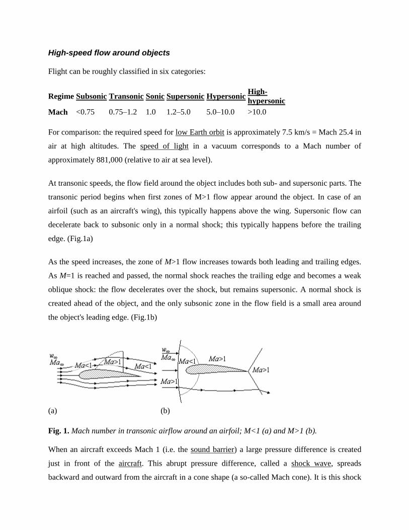
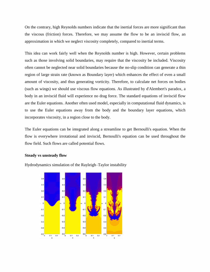
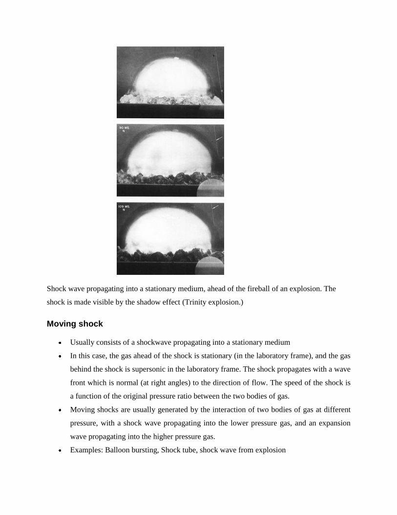
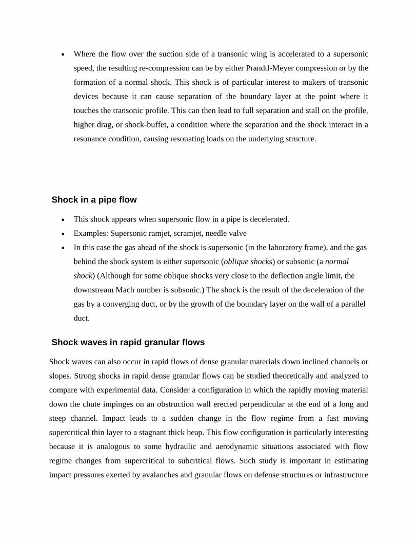
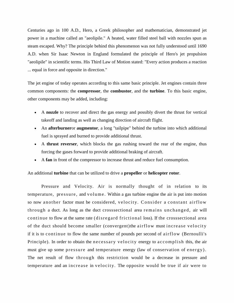
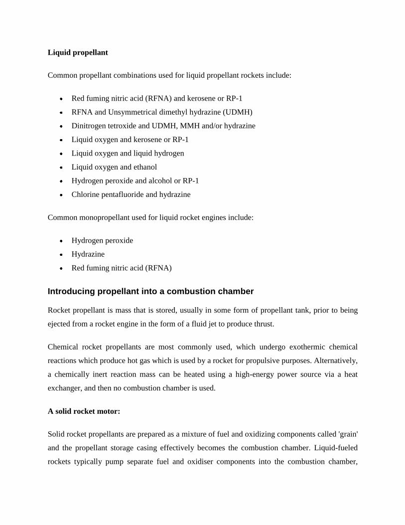
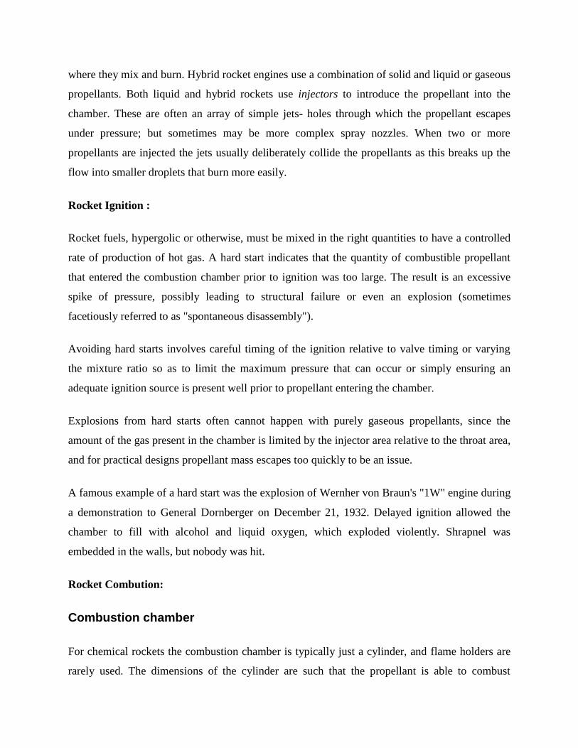