me382 and mt382 user manual - sms metering€¦ · · 2014-03-24me382 and mt382 user manual ....
TRANSCRIPT
Energy Measurement and Management
ME382 and MT382
User manual
Document code: EAK 020.615.751
Version: V1.02
Date: 13.12.2013

Mx382_User_manual_eng_V1.02.docx 2
ME382 and MT382
i. About the User manual User manual is intended to present the Mx382 meters (x stands
for E (single phase meters) or T (three phase meters).
The User manual represents the purpose of the Mx382 meters,
meter construction, the way of deriving the measured quantities
and meter functionalities.
The User manual is intended for technically qualified personnel
at energy supply companies, responsible for system planning
and system operation.
ii. Reference documents Functional description
Installation and maintenance manual
iii. Versioning
Date Version Update
13.06.2013 V1.00 First version of document
29.10.2013 V1.01 Annex 1 (ME382 object list) and Annex 2 (MT382 object list) added to the
end of the document
13.12.2013 V1.02 Type designation table updated

Mx382_User_manual_eng_V1.02.docx 3
ME382 and MT382
Table of contents
1. Safety information .............................................................................................. 13
1.1. Safety instructions ....................................................................................... 14
2. Energy metering and Mx382 meters .................................................................. 16
3. Mx382 meters introduction ................................................................................. 18
3.1. Standards and references ........................................................................... 18
3.2. Mx382 meter appearance ............................................................................ 20
3.3. Main meter properties .................................................................................. 24
3.4. Mx382 meter connection into the network ................................................... 26
3.5. Energy and demand registration.................................................................. 27
3.5.1 Energy .................................................................................................. 28
3.5.2 Demand ................................................................................................ 29
3.6. Measurement principle ................................................................................ 33
3.6.1 Energy LED impulse output .................................................................. 33
3.6.2 Energy METRO pulse output ................................................................ 33
3.6.3 Measured quantities .............................................................................. 34
3.6.4 Voltage .................................................................................................. 35
3.6.5 Current .................................................................................................. 37
3.6.6 Net frequency ........................................................................................ 37
3.6.7 Power .................................................................................................... 37
3.6.8 Power factor .......................................................................................... 38
3.6.9 Energy .................................................................................................. 38
3.6.10 Measurement period parameterization .............................................. 40
4. Meter construction.............................................................................................. 41
4.1. Technical figures and dimensions ............................................................... 41
4.2. Meter case ................................................................................................... 43
4.2.1 Terminal block ....................................................................................... 43
4.2.2 Meter cover ........................................................................................... 44
4.2.3 Terminal cover ...................................................................................... 44
4.2.4 Sealing .................................................................................................. 46
4.3. Front plate ................................................................................................... 48
4.4. Console keys ............................................................................................... 50
4.4.1 LCD ....................................................................................................... 50
Mx382_User_manual_eng_V1.02.docx 4
ME382 and MT382
4.4.2 Metrological LEDs ................................................................................. 56
4.4.3 Keys ...................................................................................................... 57
4.4.4 Display data codes ................................................................................ 66
4.5. Voltage bridge ............................................................................................. 67
5. Mx382 meter constituent parts ........................................................................... 68
5.1. Mx382 meter type designation .................................................................... 68
5.2. Inputs and outputs ....................................................................................... 69
5.2.1 Relay output - load ................................................................................ 69
5.2.2 OptoMOS output - service..................................................................... 71
5.2.3 Inputs .................................................................................................... 72
5.2.4 Active SD outputs ................................................................................. 73
5.2.5 Input/output status ................................................................................ 73
5.3. Real time clock ............................................................................................ 74
5.3.1 Time ...................................................................................................... 75
5.3.2 Status .................................................................................................... 75
5.3.3 Daylight Savings ................................................................................... 75
5.3.4 Local time and date ............................................................................... 75
5.3.5 Clock time shift limit .............................................................................. 76
5.3.6 RTC Mode ............................................................................................. 76
5.3.7 Battery Use Time Counter..................................................................... 76
5.3.8 Battery Estimated Remaining Use Time Counter .................................. 76
5.4. Activity calendar and TOU registration ........................................................ 76
5.4.1 Tariff program ....................................................................................... 77
5.4.2 Activity calendar .................................................................................... 77
5.4.3 Special days .......................................................................................... 79
5.4.4 Register activation ................................................................................ 79
5.4.5 Tariff synchronization ............................................................................ 80
5.4.6 Currently active tariff ............................................................................. 80
5.5. Communication............................................................................................ 81
5.5.1 Optical interface .................................................................................... 81
5.5.2 P1 interface ........................................................................................... 84
5.5.3 M-Bus ................................................................................................... 88
5.5.4 GSM/GPRS communication module ..................................................... 97

Mx382_User_manual_eng_V1.02.docx 5
ME382 and MT382
5.5.5 Push setup .......................................................................................... 114
5.6. Fraud detection.......................................................................................... 118
5.6.1 Meter cover open and terminal cover open ......................................... 118
5.6.2 Magnetic field detection ...................................................................... 118
5.7. Meter programming ................................................................................... 118
5.8. Configuration program change .................................................................. 119
6. Description of main meter functionalities .......................................................... 120
6.1. Measurements ........................................................................................... 120
6.2. Sequences ................................................................................................ 120
6.2.1 P1 port readout list .............................................................................. 120
6.2.2 General display readout ...................................................................... 120
6.2.3 Alternate display readout .................................................................... 121
6.3. Load profile recorder ................................................................................. 121
6.3.1 Profile .................................................................................................. 122
6.3.2 Profile status ....................................................................................... 122
6.4. Billing profile recorder ................................................................................ 123
6.4.1 End of billing period ............................................................................ 124
6.4.2 End of billing period script table .......................................................... 124
6.4.3 Billing period counter .......................................................................... 125
6.4.4 Data of billing period – Billing profile ................................................... 125
6.5. Event logs .................................................................................................. 125
6.5.1 Event code objects .............................................................................. 127
6.5.2 Event log objects ................................................................................. 127
6.5.3 Standard event log .............................................................................. 128
6.5.4 Fraud detection event log.................................................................... 129
6.5.5 Power quality event log ....................................................................... 131
6.5.6 Power failure event log ....................................................................... 131
6.5.7 Communication event log.................................................................... 132
6.5.8 Certification data log ........................................................................... 132
6.5.9 Disconnector control log ..................................................................... 133
6.5.10 M-Bus event log ............................................................................... 134
6.5.11 M-Bus control logs ........................................................................... 135
6.6. Alarms ....................................................................................................... 135
Mx382_User_manual_eng_V1.02.docx 6
ME382 and MT382
6.6.1 Alarm system ...................................................................................... 136
6.6.2 Alarm codes ........................................................................................ 136
6.6.3 Alarm register ...................................................................................... 138
6.6.4 Alarm filter ........................................................................................... 138
6.6.5 Alarm status ........................................................................................ 138
6.6.6 Alarm descriptor .................................................................................. 138
6.6.7 Alarm monitor ...................................................................................... 138
6.7. Errors ......................................................................................................... 139
6.7.1 Error register ....................................................................................... 139
6.7.2 Error filter ............................................................................................ 140
6.7.3 Error display filter ................................................................................ 141
6.7.4 Error types .......................................................................................... 141
6.8. Activity calendar and TOU registration ...................................................... 143
6.9. Disconnector – Load switch ....................................................................... 143
6.9.1 Disconnector type ............................................................................... 145
6.9.2 Disconnect control .............................................................................. 146
6.9.3 Disconnect control log ......................................................................... 147
6.10. Limitation ................................................................................................ 147
6.10.1 Limiter .............................................................................................. 148
6.10.2 Supervision monitor - IDIS ............................................................... 150
6.10.3 Supervision monitor - GIZ ................................................................ 152
6.11. Identification numbers ............................................................................ 154
6.11.1 COSEM Logical Device Name ......................................................... 154
6.11.2 System title ...................................................................................... 155
6.11.3 Device number ................................................................................ 155
6.11.4 Device ID ......................................................................................... 155
6.11.5 Medium specific ID .......................................................................... 156
6.11.6 Meter software identification ............................................................ 157
6.12. Monitoring functions ............................................................................... 158
6.12.1 Power quality ................................................................................... 158
6.12.2 Reclosing counter ............................................................................ 164
6.12.3 Watchdog counter............................................................................ 164
6.12.4 Cover opening counter .................................................................... 164

Mx382_User_manual_eng_V1.02.docx 7
ME382 and MT382
6.12.5 Breaker opening counter ................................................................. 164
6.13. Security .................................................................................................. 164
6.13.1 Physical security .............................................................................. 165
6.13.2 Logical security ................................................................................ 166
7. Technical characteristics .................................................................................. 171
7.1. ME382 meter ............................................................................................. 171
7.2. MT382 meter ............................................................................................. 174
Annex 1: ME382 object list .................................................................................... 178
Annex 2: MT382 object list .................................................................................... 190

Mx382_User_manual_eng_V1.02.docx 8
ME382 and MT382
Index of Figures Figure 1: Smart metering system .......................................................................................................... 17 Figure 2: ME382 meter appearance – front view .................................................................................. 20 Figure 3: ME382 meter appearance – bottom view .............................................................................. 21 Figure 4: MT382 meter appearance – front view .................................................................................. 22 Figure 5: MT382 meter appearance – bottom view............................................................................... 23 Figure 6: ME382 meter connection diagram – DIN connection ............................................................ 26 Figure 7: ME382 meter connection diagram – BS connection .............................................................. 26 Figure 8: MT382 meter connection diagram – direct connection .......................................................... 26 Figure 9: MT382 meter connection diagram – transformer operated meter ......................................... 27 Figure 10: Measuring principle .............................................................................................................. 27 Figure 11: Measured energy and demand ............................................................................................ 28 Figure 12: Demand calculation sample ................................................................................................. 29 Figure 13: Attributes in the case of block demand (1 period) ................................................................ 29 Figure 14: Attributes in case of sliding demand .................................................................................... 30 Figure 15: Calculation of demand over a known period with sliding window ........................................ 30 Figure 16: Calculation of demand over a known period with sliding window ........................................ 31 Figure 17: Time attributes when measuring sliding demand ................................................................. 31 Figure 18: Quadrant cross ..................................................................................................................... 38 Figure 19: Overall and fixing dimensions of the ME382 meter fitted with a long terminal cover .......... 41 Figure 20: Overall and fixing dimensions of the ME382 meter fitted with a short terminal cover ......... 41 Figure 21: Overall and fixing dimensions of an MT382 meter fitted with a long terminal cover ............ 42 Figure 22: Overall and fixing dimensions of an MT382 meter fitted with a short terminal cover .......... 42 Figure 23: Overall and fixing dimensions of the MT382 meter fitted with a disconnector and a long
terminal cover ................................................................................................................................. 43 Figure 24: Terminal cover for ME382 meter .......................................................................................... 45 Figure 25: Short terminal cover for MT382 meter ................................................................................. 45 Figure 26: Long terminal cover for MT382 meter .................................................................................. 45 Figure 27: Terminal cover for MT382 meter with disconnector unit ...................................................... 46 Figure 28: Meter connection diagram on the inner side of the terminal cover ...................................... 46 Figure 29: Positions of the seals at ME382 meter................................................................................. 47 Figure 30: Positions of the seals at MT382 meter ................................................................................. 47 Figure 31: ME382 – DIN front plate ....................................................................................................... 48 Figure 32: MT382-D1 front plate ........................................................................................................... 48 Figure 33: MT382-D2 front plate ........................................................................................................... 49 Figure 34: MT382-T1 front plate ............................................................................................................ 49 Figure 35: Full Mx382 LCD – display fields ........................................................................................... 50 Figure 36: Characters represented on a display ................................................................................... 51 Figure 37: LCD cursors ......................................................................................................................... 52 Figure 38: Displaying value with format “60“ ......................................................................................... 53 Figure 39: Dislpaying value with format “82“ ......................................................................................... 53 Figure 40: Displaying negative value with format “42“ .......................................................................... 53 Figure 41: Displaying negative value with format “80“ .......................................................................... 53 Figure 42: Displaying negative value with improper format “42“ according to register value ............... 54 Figure 43: Ident format failed message ................................................................................................. 54 Figure 44: Tariff on display .................................................................................................................... 56 Figure 45: Signature on display ............................................................................................................. 56 Figure 46: LEDs at ME382 meter .......................................................................................................... 57 Figure 47: LEDs at MT382 meter .......................................................................................................... 57
Mx382_User_manual_eng_V1.02.docx 9
ME382 and MT382
Figure 48: Reset and Scroll key ........................................................................................................... 57 Figure 49: Menu navigation diagram for reduced console .................................................................... 59 Figure 50: Entering the Data/Set menu ................................................................................................. 61 Figure 51: Data menu navigation .......................................................................................................... 61 Figure 52: Set menu navigation............................................................................................................. 62 Figure 53: Manual-scroll mode navigation ............................................................................................ 63 Figure 54: Load profile on display navigation ........................................................................................ 64 Figure 55: LCD test mode navigation .................................................................................................... 65 Figure 56: Meter reset procedure .......................................................................................................... 66 Figure 57: Sliding voltage bridge ........................................................................................................... 67 Figure 58: Load control terminal ............................................................................................................ 69 Figure 59: Relay state transitions .......................................................................................................... 70 Figure 60: Service control terminal ........................................................................................................ 71 Figure 61: Mx382 input terminals .......................................................................................................... 73 Figure 62: Time and Date Data Format ................................................................................................. 75 Figure 63: Set date and time ................................................................................................................. 76 Figure 64: Graphical tariff program ....................................................................................................... 77 Figure 65: Optical interface ................................................................................................................... 81 Figure 66: IEC optical port communication profile................................................................................. 82 Figure 67: COSEM/DLMS optical port communication profile .............................................................. 82 Figure 68: Diagram for connecting device to P1 port ............................................................................ 85 Figure 69: P1 port connection ............................................................................................................... 86 Figure 70: P1 port data string ................................................................................................................ 88 Figure 71: M-Bus master-slave configuration and dongle interface ...................................................... 89 Figure 72: M-Bus channel model........................................................................................................... 89 Figure 73: Keys ..................................................................................................................................... 92 Figure 74: Example for channel ............................................................................................................ 92 Figure 75: M-Bus disconnect state diagram ......................................................................................... 94 Figure 76: State transitions during a successful call establishment procedure .................................. 100 Figure 77: GPRS connection establishment process .......................................................................... 102 Figure 78: Destination_SAP and Source_SAP ................................................................................... 104 Figure 79: IDIS client and server model .............................................................................................. 105 Figure 80: TCP/IP based COSEM communication profiles ................................................................. 110 Figure 81: The COSEM wrapper protocol data unit (WPDU) .............................................................. 111 Figure 82: Auto connect operation in “Always ON“ modes during defined time window .................... 112 Figure 83: Auto connect operation in modes 103 and 104 when a connection method is invoked .... 112 Figure 84: Power down scenario 1 ...................................................................................................... 116 Figure 85: Power down scenario 2 ...................................................................................................... 116 Figure 86: Power down scenario 3 ...................................................................................................... 117 Figure 87: Power down scenarion 4 .................................................................................................... 117 Figure 88: Terminal cover opening switch ........................................................................................... 118 Figure 89: Event handling .................................................................................................................... 126 Figure 90: Alarm reporting process ..................................................................................................... 136 Figure 91: Error filtering ....................................................................................................................... 140 Figure 92: Disconnector for MT382-D1 ............................................................................................... 143 Figure 93: Disconnector for MT382-D2 ............................................................................................... 144 Figure 94: MT382 meter with disconnector ......................................................................................... 144 Figure 95: Disconnect state control diagram ....................................................................................... 145
Mx382_User_manual_eng_V1.02.docx 10
ME382 and MT382
Figure 96: Limiter diagram ................................................................................................................... 149 Figure 97: Monitoring phase current with constant threshold parameter ............................................ 153 Figure 98: COSEM Logical Device Name Structure ........................................................................... 154 Figure 99: Identification Structure ....................................................................................................... 157 Figure 100: Revision Number Structure .............................................................................................. 157 Figure 101a: Voltage sampling ............................................................................................................ 159 Figure 101b: Voltage sampling ............................................................................................................ 160 Figure 102: Voltage Asymmetry Calculation ....................................................................................... 162 Figure 103: Unexpected consumption ................................................................................................. 163 Figure 104: Intended neutral N-N' ....................................................................................................... 163 Figure 105: Power fail example ........................................................................................................... 164 Figure 106: Meter and Terminal cover tamper logging ....................................................................... 165 Figure 107: Encryption and decryption procedure .............................................................................. 167
Index of Tables Table 1: All total and rate energy registers ............................................................................................ 28 Table 2: Last average demand registers ............................................................................................... 32 Table 3: Maximum demand registers – total ......................................................................................... 32 Table 4: List of metropulse output function enumeration ...................................................................... 33 Table 5: Instantaneous voltage objects in the MT880 meter ................................................................ 35 Table 6: Peak and minimum values of voltage ...................................................................................... 36 Table 7: Average values of voltage ....................................................................................................... 36 Table 8: Voltage levels .......................................................................................................................... 36 Table 9: Magnitude for voltage sags and swells ................................................................................... 36 Table 10: Magnitude of last voltage sag and swell................................................................................ 36 Table 11: Instantaneous current objects ............................................................................................... 37 Table 12: Sliding average current ......................................................................................................... 37 Table 13: Instantaneous net frequency object ...................................................................................... 37 Table 14: Instantaneous power objects ................................................................................................. 37 Table 15: Average power ...................................................................................................................... 37 Table 16: Instantaneous power factor objects ....................................................................................... 38 Table 17: Last average power factor ..................................................................................................... 38 Table 18: Total energy objects .............................................................................................................. 39 Table 19: Tariff energy registers ........................................................................................................... 39 Table 20: Average demand objects ....................................................................................................... 40 Table 21: Last demand objects ............................................................................................................. 40 Table 22: Maximum demand objects .................................................................................................... 40 Table 23: MP configuration objects ....................................................................................................... 40 Table 24: LCD cursors ........................................................................................................................... 52 Table 25: OBIS name abbreviation characters ..................................................................................... 54 Table 26: Error codes on display ........................................................................................................... 55 Table 27: Use of keys – normal console menu type ............................................................................. 60 Table 28: Key labels .............................................................................................................................. 60 Table 29: Display register codes ........................................................................................................... 67 Table 30: Meter type designation .......................................................................................................... 69 Table 31: Disconnect modes ................................................................................................................. 71 Table 32: Input state control register ..................................................................................................... 73 Table 33: Output state control register .................................................................................................. 74
Mx382_User_manual_eng_V1.02.docx 11
ME382 and MT382
Table 34: Output state control register .................................................................................................. 74 Table 35: Active tariff register ................................................................................................................ 81 Table 36: RJ11 pins ............................................................................................................................... 86 Table 37: M-Bus disconnector modes ................................................................................................... 95 Table 38: M-Bus alarms ........................................................................................................................ 97 Table 39: GSM status ............................................................................................................................ 99 Table 40: SMS centre address setting ................................................................................................ 103 Table 41: Auto answer SMS list allowed callers .................................................................................. 103 Table 42: Push setup list ..................................................................................................................... 105 Table 43: Example of SMS PDU ......................................................................................................... 107 Table 44: Concatenated SMS ............................................................................................................. 108 Table 45: Modem reset triggers........................................................................................................... 109 Table 46: GSM status object bits B1 and B11 relation states and meaning ....................................... 114 Table 47: List of profile statuses .......................................................................................................... 123 Table 48: Event log objects ................................................................................................................. 127 Table 49: List of events in the Standard event log .............................................................................. 129 Table 50: List of events in the Fraud detection event log .................................................................... 130 Table 51: List of events in the Power quality event log ....................................................................... 131 Table 52: List of events in the Communication event log .................................................................... 132 Table 53: List of events in the Disconnector control log ...................................................................... 133 Table 54: List of events in the M-Bus event log .................................................................................. 134 Table 55: List of events in the M-Bus control log ................................................................................ 135 Table 56: Alarm 1 codes (IDIS P1/P2) ................................................................................................ 137 Table 57: Alarm 2 codes (IDIS P2) ...................................................................................................... 138 Table 58: IDIS error codes register ..................................................................................................... 140 Table 59: IE error codes register ......................................................................................................... 140 Table 60: Disconnect transitions ......................................................................................................... 145 Table 61: Disconnector modes ............................................................................................................ 147 Table 62: The IDIS Device Type Meaning .......................................................................................... 154 Table 63: The IDIS Function Type Meaning ........................................................................................ 154 Table 64: COSEM logical device name example 1 ............................................................................. 155 Table 65: COSEM logical device name example 2 ............................................................................. 155 Table 66: Meaning of Revision Number Characters ........................................................................... 158 Table 67: Dip & swell detection model ................................................................................................ 159 Table 68: Set of supported clients ....................................................................................................... 168 Table 69: Supported authentication mechanism names ..................................................................... 168 Table 70: Application context names .................................................................................................. 169 Table 71: Security suite ....................................................................................................................... 170

Mx382_User_manual_eng_V1.02.docx 12
ME382 and MT382
Disclaimer
Iskraemeco, d.d. reserves the right to change these document at any time without prior notice. No part of this document may be reproduced, stored or transmitted in any form whatsoever without prior written approval of Iskraemeco, d.d..
This document is for information only. The content of this document should not be construed as a commitment, representation, warranty, or guarantee for any method, product, or device by Iskraemeco,d.d.
and are registered trademarks of Iskraemeco, d.d.. The contents of this document are the copyrighted (registered and unregistered) or trademarked property of Iskraemeco, d.d. and are protected under applicable trademark and copyright law. Unauthorized use may be subject to criminal and material liability.

Mx382_User_manual_eng_V1.02.docx 13
ME382 and MT382
1. Safety information
Safety information used in this user manual is described with the following symbols and pictographs:
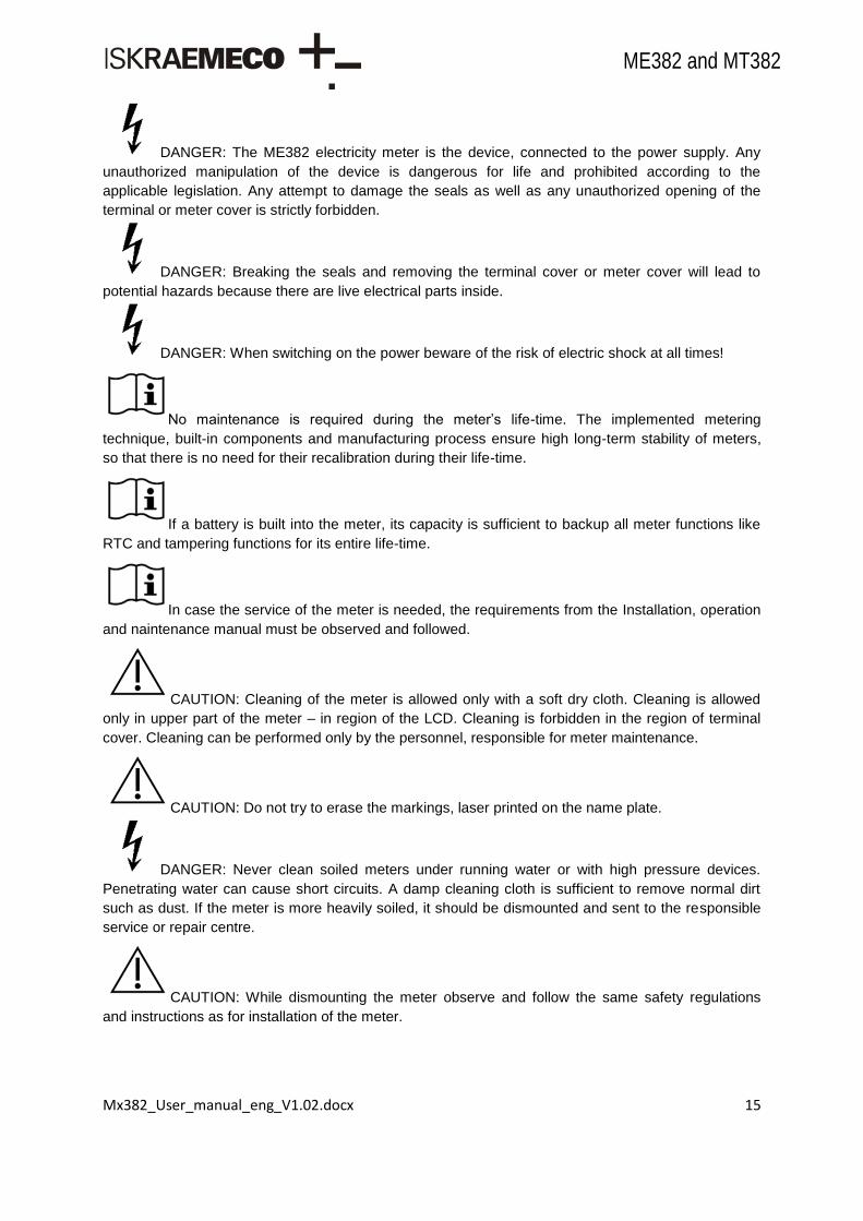
DANGER: for a possibly dangerous situation, which could result in severe physical
injury or fatality – attention to a high risk hazards.
CAUTION: for a possibly dangerous situation, which could result in minor physical
injury or material damage - attention to a medium risk hazards.
Operating instruction: for general details and other useful information.
All safety information in this user manual describes the type and source of danger, its possible
consequences and measures to avoid the danger.
Responsibilities
The owner of the meter is responsible to assure that all authorized persons who work with the meter
read and understand the parts of the User manual that explains the safe handling with the meter.
The personnel must be sufficiently qualified for the work that will be performed.
The personnel must strictly follow the safety regulations and operating instructions, written in the
individual chapters in this User manual.
The owner of the meter respond specially for the protection of the persons, for prevention of material
damage and for training of personnel.
Safety measures should be observed at all times. Do not break the seals or open the meter at any time!

Mx382_User_manual_eng_V1.02.docx 14
ME382 and MT382
1.1. Safety instructions
CAUTION: At the beginning of handling with the meter, the meter should be carefully taken
out of the box where it was packed. This should prevent the meter from falling as well as any other
external or internal damage to the device and personal injuries. Should such an incident occur despite
all precautions, the meter may not be installed at the metering point as such damage may result in
different hazards. In such case the meter needs to be sent back to the manufacturer for examination
and testing.
CAUTION: The edges of the seal wires are sharp.
CAUTION: The temperature of the terminal block of the connected and operating meter
may rise, therefore the temperature of the terminal cover may rise as well.
DANGER: In case of any damage inside the meter (fire, explosion...) do not open the meter.
CAUTION: The meter may be used only for the purpose of measurement for which it was
produced. Any misuse of the meter will lead to potential hazards.
WARNING: Safety measures should be observed at all times. Do not break the seals or open the meter at any time!
The content of this User manual provides all information necessary for safe selection of MT382 meter.
See the complete User manual for detailed technical features of MT382 and its intended
use.
It must be consulted in all cases where symbol is marked in order to find out the nature of
the potential hazards and any actions which have to be taken to avoid them.
The meter installation procedure is described in the Installation and maintenance manual. For safety
reasons the following instructions should be followed.
Only the properly connected meter can measure correctly. Every connecting error results in
a financial loss for the power company.
Mx382_User_manual_eng_V1.02.docx 15
ME382 and MT382
DANGER: The ME382 electricity meter is the device, connected to the power supply. Any
unauthorized manipulation of the device is dangerous for life and prohibited according to the
applicable legislation. Any attempt to damage the seals as well as any unauthorized opening of the
terminal or meter cover is strictly forbidden.
DANGER: Breaking the seals and removing the terminal cover or meter cover will lead to
potential hazards because there are live electrical parts inside.
DANGER: When switching on the power beware of the risk of electric shock at all times!
No maintenance is required during the meter‟s life-time. The implemented metering
technique, built-in components and manufacturing process ensure high long-term stability of meters,
so that there is no need for their recalibration during their life-time.
If a battery is built into the meter, its capacity is sufficient to backup all meter functions like
RTC and tampering functions for its entire life-time.
In case the service of the meter is needed, the requirements from the Installation, operation
and naintenance manual must be observed and followed.
CAUTION: Cleaning of the meter is allowed only with a soft dry cloth. Cleaning is allowed
only in upper part of the meter – in region of the LCD. Cleaning is forbidden in the region of terminal
cover. Cleaning can be performed only by the personnel, responsible for meter maintenance.
CAUTION: Do not try to erase the markings, laser printed on the name plate.
DANGER: Never clean soiled meters under running water or with high pressure devices.
Penetrating water can cause short circuits. A damp cleaning cloth is sufficient to remove normal dirt
such as dust. If the meter is more heavily soiled, it should be dismounted and sent to the responsible
service or repair centre.
CAUTION: While dismounting the meter observe and follow the same safety regulations
and instructions as for installation of the meter.

Mx382_User_manual_eng_V1.02.docx 16
ME382 and MT382
CAUTION: Visible signs of fraud attempt (mechanical damages, presence of a liquid, etc.)
must be regularly checked. The quality of seals and the state of the terminals and connecting cables
must be regularly checked. If there exist a suspicion of incorrect operation of the meter, the local utility
must be informed immediatelly.
After the end of the meter‟s lifetime, the meter should be treated according to the Waste
Electric and Electronic Directive (WEEE).
2. Energy metering and Mx382 meters
Mx382 family meters are designed for up to eight tariff measuring of active, reactive and apparent energy in one or two energy flow directions. The meter measures consumed energy in single-phase two-wire networks or three-phase four-wire network for direct or indirect connection. Measuring and technical characteristics of the meter comply with the IEC 62052-11 and IEC 62053-21 international standards for electronic active energy meters, class 1 and 2, and reactive energy meters, classes 2 or 3 in compliance with IEC 62053-23 as well as a standard for time switches IEC 62052-21.
Meters are designed and manufactured in compliance with the standards and ISO 9001 as well as more severe Iskraemeco standards. Meter utilizes the DLMS communication protocol in compliance with the IEC 62056-46 standard as well as IEC 62056-21, mode C protocol. The Mx382 meters are members of the third generation of Iskraemeco electronic single and three-phase meters for a deregulated market of electric power, with the following common functional properties:
Time-of-use measurement of active energy and maximum demand (in up to 8 tariffs),
Load-profile registration,
LCD in compliance with the VDEW specification, with two modes of data display,
Internal real-time clock,
Two keys: Reset and Scroll key,
Optical port (IEC 62056-21 standard) for local meter programming and data downloading,
Built-in interface (IR) and GSM/GPRS modem for a remote two-way communication, meter programming and data downloading,
Wired M-Bus,
Alarm input,
Non-potential key input,
Opto-MOS o switching functionality (for low current loads), o metropulse functionality (configurable energy pulses),
Bi-stabile relay o switching external loads up to 6A, o external disconnector functionality,
Integrated disconnector with 1-phase meters,
External disconnector with 3-phase meters (option). Further to the Mx382 meters functionality they also enable:

Mx382_User_manual_eng_V1.02.docx 17
ME382 and MT382
Detectors of the meter and the terminal block covers opening,
Disconnector for remote disconnection / reconnection of the customer premises,
M-Bus for reading other meters (heat, gas, water),
Remote display ON/OFF configuration,
Two different console type (reduced and normal),
Third party disconnector driven through rele.
Figure 1: Smart metering system
Mx382_User_manual_eng_V1.02.docx 18
ME382 and MT382
3. Mx382 meters introduction
3.1. Standards and references
EN 13757-1 Communication systems for meters and remote reading of meters Part 7: Data exchange.
EN 13757-2 Communication systems for meters and remote reading of meters Part 2: Physical and link Layer
EN 13757-3 Communication systems for meters and remote reading of meters Part 3: Dedicated application Layer
EN 13757-4 Communication systems for meters and remote reading of meters Part 4: Wireless meter readout (Radio Meter reading for operation in the 868-
870 MHz SRD band)
IEC 62056–21 Data exchange for meter reading, tariff and load control - Direct local
connection (3rd edition of IEC 61107)
IEC 62056-46 Electricity metering; Data exchange for meter reading, tariff and load control;
Data link layer using HDLC-Protocol
IEC 62056-47 Electricity metering; Data exchange for meter reading, tariff and load control;
COSEM transport layers for IPv4 networks
IEC 62056-53 Electricity metering; Data exchange for meter reading, tariff and load control
COSEM Application Layer
IEC 62056-61 Electricity metering; Data exchange for meter reading, tariff and load control
obis object identification system (OBIS)
IEC 62053-21 Electricity metering equipment; Particular requirements; Electronic meters for
active energy (classes 1 and 2)
IEC 62053-23 Electricity metering equipment (AC.); Particular requirements; Static meters for reactive energy (classes 2 and 3)
IEC 62052-11 Electricity metering equipment (AC.): General requirements, tests and test conditions - Metering equipment
IEC 62052-21 Electricity metering equipment (AC.) General requirements, tests and test conditions - Tariff and load control equipment
IEC 61334-4-32 Distribution automation using distribution line carrier systems - Data communication protocols - Data link layer - Logical link control (LLC)
IEC 61334-4-512 Distribution automation using distribution line carrier systems - Data communication protocols - System management using profile 61334-5-1 - Management Information Base (MIB)

Mx382_User_manual_eng_V1.02.docx 19
ME382 and MT382
IEC 61334-5-1 Distribution automation using distribution line carrier systems - Lower layer profiles - The spread frequency shift keying (S-FSK) profile
ISO/IEC 8802.2 Information technology - Telecommunications and information exchange
between systems - Local and metropolitan area networks - Specific requirements; Logical link control
RFC 1321 MD5 Message-Digest Algorithm
RFC 1332 The Internet Protocol Control Protocol (IPCP)
RFC 1570 PPP Link Control Protocol (LCP) Extensions
RFC 1661 Standard 51, The Point-to-Point Protocol (PPP)
RFC 1662 Standard 51, PPP in HDLC-like Framing
RFC 1700 Assigned Numbers
RFC 2507 IP Header Compression
RFC 3241 Robust Header Compression
FIPS PUB 180-1 Secure Hash Algorithm
IEC 60529 Degrees of protection provided by enclosures (IP code)
COSEM Blue Book 10th Edition, DLMS UA 1000-1:2010, Ed. 10.0, 2010-08-26
COSEM Green Book 7th Edition, DLMS UA 1000-2:2010, Ed. 7.0, 209-12-22
IDIS Package 2 IP Profile ed. 1.0.docx
Iskraemeco technical notes
IDIS - object model - V2.10 (20120823).xlsx
VDEW- specification for “Electronic Meters with load curve“ Version 2.1.2 i7th November 2003
IP Header Compression over PPP

Mx382_User_manual_eng_V1.02.docx 20
ME382 and MT382
3.2. Mx382 meter appearance
Figure 2: ME382 meter appearance – front view
Item Description
1 Liquid crystal display (LCD)
2 Meter serial number
3 Meter technical data
4 Coupling circuit
5 Meter cover sealing screw
6 Terminal cover
7 Terminal cover sealing screw
8 Right side – Active energy Impulse LED Left side – Reactive energy Impulse LED
9 Scroll and Reset keys
10 Lid sealing screw
11 IR optical interface
1
2
3
4
5
6
11
10
9
8
5
7

Mx382_User_manual_eng_V1.02.docx 21
ME382 and MT382
Figure 3: ME382 meter appearance – bottom view
Item Description
1 SIM card holder
2 Switch for detection of terminal cover opening
3 Screw for fitting current cables
4 Additional voltage terminals (option)
5 Current terminals
6 Neutral terminals
7 Auxiliary terminals (Load control output, M-Bus communication interface)
8 Alarm input
9 Non-potential key input
10 Port P1
1
2
3
4
5
10
9
8
7
7
6
Mx382_User_manual_eng_V1.02.docx 22
ME382 and MT382
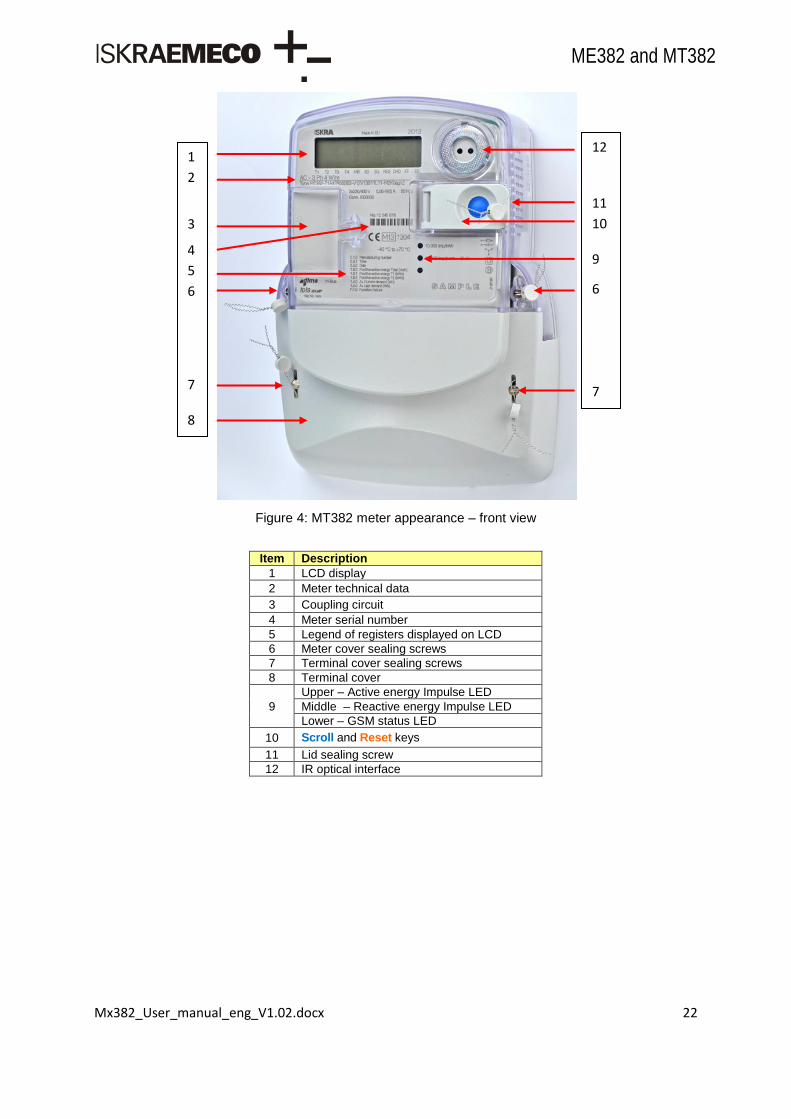
Figure 4: MT382 meter appearance – front view
Item Description
1 LCD display
2 Meter technical data
3 Coupling circuit
4 Meter serial number
5 Legend of registers displayed on LCD
6 Meter cover sealing screws
7 Terminal cover sealing screws
8 Terminal cover
9
Upper – Active energy Impulse LED
Middle – Reactive energy Impulse LED
Lower – GSM status LED
10 Scroll and Reset keys
11 Lid sealing screw
12 IR optical interface
1
2
3
4
5
6
7
8
12
11
10
9
6
7

Mx382_User_manual_eng_V1.02.docx 23
ME382 and MT382
Figure 5: MT382 meter appearance – bottom view
Item Description
1 Port P1
2 SIM card holder
3 Screw for fitting current cables
4 Current terminals
5 Neutral terminals
6 Auxiliary terminals (Load control output, M-Bus communication interface)
7 Additional voltage terminals
8 Switch for detection of terminal cover opening
9 Connector for disconector unit
10 Non-potential key
11 Alarm input
1
2
3
4
11
10
9
8
6
7
6
5

Mx382_User_manual_eng_V1.02.docx 24
ME382 and MT382
3.3. Main meter properties
Active energy and demand meter of accuracy class 1 or 2 (in compliance with IEC 62053-21).
Reactive energy and demand meter of accuracy class 2 or 3 (in compliance with IEC 62053-23).
Apparent energy meter of accuracy class 2 or 3.
Modes of energy measurement and registration (single-phase meters): • For one-way energy flow direction, • For two-way energy flow direction,
• For two-way energy flow direction but registered in one (absolute) register. Modes of energy measurement and registration (three-phase meters):
• For one-way energy flow direction, three-phase energy is algebraic (arithmetical) sum of energies registered, in each of the phases – meters are equipped with an electronic reverse running stop,
• For two-way energy flow direction, three-phase energy is algebraic (arithmetical) sum of energies registered in each of the phases,
• For one-way energy flow direction, three-phase energy is sum of absolute values of energies registered in each of the phases.
Meter quality: • Due to high accuracy and long term stability of metering elements no meter re-
calibration over its life-time is required, • High meter reliability, • High immunity to EMC.
Additional meter functions: • Detection of missing/broken neutral conductor, • Detection of phase and voltage unbalance, • Measurement and registration of under- and over-voltage, • Daily peak and minimum value.
Time-of-use registration (up to 8 tariffs): Tariffs change-over; internal RTC (by IEC 61038).
Two Load-profile recorders.
Communication channels: • Infrared optical port (IEC 62056-21) for local meter programming and data downloading, • Built-in GSM/GPRS modem, • Built-in M-Bus communication interface, • Built-in RJ11 communication interface (one way).
LCD: In compliance with the VDEW specification.
Data display modes (configurable): Reduced type:
Automatic cyclic data display (10 sec display time),
Manual data display mode (by pressing the Scroll key). Normal type (according to VDEW):
Automatic cyclic data display mode,
Manual data display mode,
Load profile 1 (configurable),
Load profile 2 (configurable).
Indicators: LCD:
• Presence of phase voltages L1, L2, L3, • Phase currents flow direction, • Active tariff at the moment, • Status of a disconnector, • Communication status, • Meter network status • Critical error status (Fatal Fault), • Status of at least one M-Bus device installed in meter,

Mx382_User_manual_eng_V1.02.docx 25
ME382 and MT382
• Status of DRO in progress. LED1: Imp/kWh. LED2: Imp/kVArh or Imp/kVAh.
Communication protocols: • Optical port: IEC 62056 – 21, mode C or DLMS (in compliance with IEC 62056 – 46), • Identification system; IEC 62056 – 61, • COSEM organization of data: IEC 62056-53, • M-Bus: EN 13757-2 and EN 13757-3.
OBIS data identification code: IEC 62056–61.
Auxiliary inputs / outputs: • Output for load control with a 6A relay, • Output for load control with an OptoMOS relay, • Alarm input, • External key input, • M-Bus interface to which up to 4 gas, heat or water meters can be connected, • Active disconnector output (MT382).
Automatic configuration of an AMR system: Meters are registered automatically into an AMR system.
Programming of the meter as well as FW upgrade can be done locally (via an optical port) or remotely in compliance with the predefined security levels.
Detection of opening meter and terminal block covers.
Simple and fast meter installation.
Current terminals: • Make good contact with current conductors regardless of their design and material, • Do not damage conductors.
Voltage terminals: • Internal and/or external connection, • A sliding bridge (for simple separation of a voltage part from a current part) (only at
direct connected meters). The sliding bridges can be accessible when terminal cover is removed, or they can be hidden under the meter cover.
Compact plastic meter case: • Made of high quality self-distinguishing UV stabilized material that can be recycled, • IP54 protection against dust and water penetration (by IEC 60529).

Mx382_User_manual_eng_V1.02.docx 26
ME382 and MT382
3.4. Mx382 meter connection into the network
The meter connection diagrams for Mx382 meters are shown on the following four Figures:
Figure 6: ME382 meter connection diagram – DIN connection
Figure 7: ME382 meter connection diagram – BS connection
Figure 8: MT382 meter connection diagram – direct connection

Mx382_User_manual_eng_V1.02.docx 27
ME382 and MT382
Figure 9: MT382 meter connection diagram – transformer operated meter
3.5. Energy and demand registration
The meter measures and records electric energy:
Single-phase two wire,
Three-phase four-wire networks:
• total ( Li), • positive and negative active energy (A+, A-) separately, • reactive energy per quadrants (QI, QII, QIII, QIV), • positive and negative reactive energy (Q+, Q-) separately (Q+=QI+QII, Q-=QIII+QIV), • positive and negative apparent energy (S+, S-) separately,
• absolute active energy A .
Meters are provided with two LEDs on the front plate. They are intended for checking the meter
accuracy. Impulse constant depends on the meter version.
Power is measured inside a measuring period. The measuring period is a meter parameter and can be
set. Values that can be set are 1, 5, 10, 15, 30 and 60 minutes. After termination of the measuring
period, the measured meter value is transferred from current measuring period registers to registers
for previous measuring period that can be later used for the formation of billing values.
Values are recorded for each tariff and stored in corresponding tariff register from 1 to 8.
Figure 10: Measuring principle

Mx382_User_manual_eng_V1.02.docx 28
ME382 and MT382
Figure 11: Measured energy and demand
3.5.1 Energy
Electrical meter energy is accumulated in respective registers (A+ or A-) until 1 Wh is reached thus
energy measurement is carried out in latter unit. Default representation of the energy values on display
is in kWh with 6 digits without decimals. This representation can be changed via communication
interfaces writing appropriate string in COSEM objects as shown console description (see console
section). Nevertheless full value with each Wh counted could be obtained through communication
interfaces in form of value, unit and scaler.
The micro-computer records different types of energy (active, reactive, apparent) for all phases in one
or more tariffs (rates) and stores these values in various registers according to energy direction and
active tariff (rates).
Several energy types (A+, A-, Q+, Q-, QI, QII, QIII, QIV, S+, S-, ABS and NET) are registered as total
register value and rate ragister values.
total tariff
A+ 1.8.0 1.8.e
A- 2.8.0 2.8.e
Q+ 3.8.0 3.8.e
Q- 4.8.0 4.8.e
QI 5.8.0 5.8.e
QII 6.8.0 6.8.e
QIII 7.8.0 7.8.e
QIV 8.8.0 8.8.e
S+ 9.8.0 9.8.e
S- 10.8.0 10.8.e
ABS = IA+I + IA-I 15.8.0 15.8.e
NET = IA+I - IA-I 16.8.0 /
<e> is used as tariff index from 1 to 8
Table 1: All total and rate energy registers
- Cumulative Max Demand Plus (All,T1-T8) - Maximum Demand Plus (All,T1-T8) - Energy Plus (All,T1-T8) - Cumulative Max Demand Minus (All,T1-T8) - Maximum Demand Minus (All,T1-T8) - Energy Minus (All,T1-T8) ----------------------------------------------------------- - Active Max. Demand Absolute (All,T1-T8) - Energy Absolute (All,T1-T8) ----------------------------------------------------------- - Current, Voltage L1 - L3
P (1-0:1.4.0 - 1-0:2.8.8) Q (1-0:3.4.0 - 1-0:4.8.8) S (1-0:9.4.0 - 1-0:10.8.8)
Pd abs ( 1-0:15.4.0 - 1-0: 15.6.8 ) E ( 1-0:15.8.0 - 1-0: 15.8.8 )
U/I ( 1-0:31.7.0 - 1-0: 72.7.0 )
Q+ S+
P+
Q- S-
P-
Mx382_User_manual_eng_V1.02.docx 29
ME382 and MT382
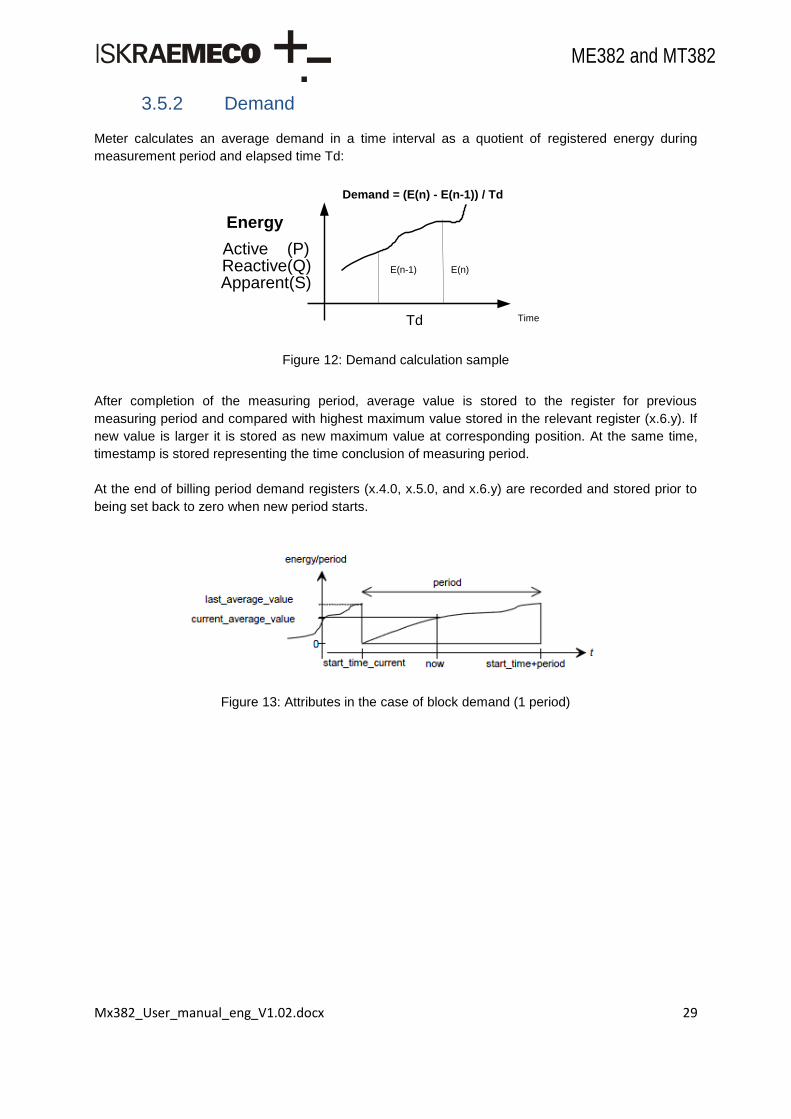
3.5.2 Demand
Meter calculates an average demand in a time interval as a quotient of registered energy during
measurement period and elapsed time Td:
Figure 12: Demand calculation sample
After completion of the measuring period, average value is stored to the register for previous
measuring period and compared with highest maximum value stored in the relevant register (x.6.y). If
new value is larger it is stored as new maximum value at corresponding position. At the same time,
timestamp is stored representing the time conclusion of measuring period.
At the end of billing period demand registers (x.4.0, x.5.0, and x.6.y) are recorded and stored prior to
being set back to zero when new period starts.
Figure 13: Attributes in the case of block demand (1 period)
Active (P)Reactive(Q)Apparent(S)
TimeTd
E(n)E(n-1)
Energy
Demand = (E(n) - E(n-1)) / Td
Mx382_User_manual_eng_V1.02.docx 30
ME382 and MT382
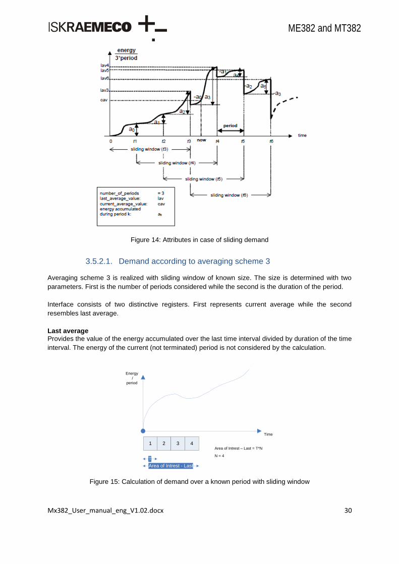
Figure 14: Attributes in case of sliding demand
3.5.2.1. Demand according to averaging scheme 3
Averaging scheme 3 is realized with sliding window of known size. The size is determined with two
parameters. First is the number of periods considered while the second is the duration of the period.
Interface consists of two distinctive registers. First represents current average while the second
resembles last average.
Last average Provides the value of the energy accumulated over the last time interval divided by duration of the time
interval. The energy of the current (not terminated) period is not considered by the calculation.
1 2 3 4
Energy
/
period
Time
Area of Intrest - Last
T
Area of Intrest – Last = T*N
N = 4
Figure 15: Calculation of demand over a known period with sliding window

Mx382_User_manual_eng_V1.02.docx 31
ME382 and MT382
Current Average This attribute provides the current value (running demand) of the energy accumulated over area of
interest – Current time interval.
Energy
/
period
Time
1 2 3 4 t
T
Area of Intrest-Curr
Area of Intrest – Curr = T*(N-1) + t
N = 4
Figure 16: Calculation of demand over a known period with sliding window
3.5.2.2. Sliding demand registers
COSEM Demand Register class allows modeling values, with its associated scaler, unit, status and
time information.
A “Demand register” object measures and computes a current_average_value periodically, and stores
last_average_value. The time interval T over which the demand is measured or computed is defined
by specifying number_of_periods and period attributes. The figure below presents how time attributes
are ment to be used with the Demand register class.
Figure 17: Time attributes when measuring sliding demand
3.5.2.3. Other demand registers
In addition to sliding demand registers Mx382 meter also has other demand measuring registers.

Mx382_User_manual_eng_V1.02.docx 32
ME382 and MT382
Last average Demand Registers
Last demand registers (x.5.0) represent same values as attribute 3 of average demand registers. They
are stored as separate registers for possible display on LCD.
SUM tariff
A+ 1.5.0 x
A- 2.5.0 x
Q+ 3.5.0 x
Q- 4.5.0 x
S+ 9.5.0 x
S- 10.5.0 x
ABS = IA+I + IA-I 15.5.0 x
Table 2: Last average demand registers
Maximum Demand Registers (total) Maximum demand registers represent the biggest CAV (Current Average Value) from average
demand registers, measured in one period. At the end of each measurement period, CAV from x.4.0
register (attribute 2) is compared to maximum demand value – if CAV is bigger, it replaces the value
stored in maximum demand register. Maximum demand values are set to 0 at the end of billing period.
COSEM Extended register class is used for maximum demand registers. Houdini meter provides 63
total demand registers:
SUM tariff
A+ 1.6.0 1.6.e
A- 2.6.0 2.6.e
Q+ 3.6.0 3.6.e
Q- 4.6.0 4.6.e
S+ 9.6.0 9.6.e
S- 10.6.0 10.6.e
ABS = IA+I + IA-I 15.6.0 15.6.e
<e> is used as tariff index from 1 to 8
Table 3: Maximum demand registers – total
3.5.2.4. Time management
Whenever time in meter (meter clock) is changed it comes to one of two possible events – time
change or time synchronization.
Time synchronization is treated whenever the difference between new and old time does not exceed
certain thresholds. For demand registers those thresholds are:
time_set_threshold in object Clock time shift limit (1-0:0.9.11.255),
time shift is smaller than 1% of respective measurement period but no bigger than 9s (VDEW).
Time synchronization event has no effect on demand registers, because time change is too small.
Nevertheless if more than one time synchronization per measurement period occurs, every second
synchronization is treated as appropriate time change (second time synchronization forward/backward
is treated as time change forward/backward).
If the above mentioned thresholds are exceeded, time change is treated by meter. All time change use
cases are presented in next chapter.
Mx382_User_manual_eng_V1.02.docx 33
ME382 and MT382
3.6. Measurement principle
One (ME382) or three (MT382) metering elements can be built in the meter. The current sensor for MT382 meters is Rogowsky coil (a current transformer with an air core) and shunt for ME382 meter, while voltage sensor is a resistive voltage divider. Signals of currents and voltages are fed into the A/D converters and there further processed.
3.6.1 Energy LED impulse output
There are two metrological LED‟s on the meter (See Chapter: 4.4.1)
Active LED,
Reactive LED / Apparent LED.
LED pulse blink duration is 30ms.
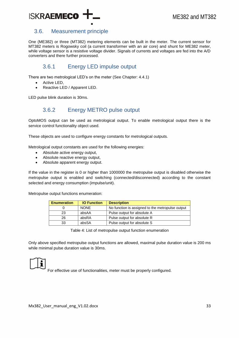
3.6.2 Energy METRO pulse output
OptoMOS output can be used as metrological output. To enable metrological output there is the
service control functionality object used.
These objects are used to configure energy constants for metrological outputs.
Metrological output constants are used for the following energies:
Absolute active energy output,
Absolute reactive energy output,
Absolute apparent energy output.
If the value in the register is 0 or higher than 1000000 the metropulse output is disabled otherwise the
metropulse output is enabled and switching (connected/disconnected) according to the constant
selected and energy consumption (impulse/unit).
Metropulse output functions enumeration:
Enumeration IO Function Description
0 NONE No function is assigned to the metropulse output
23 absAA Pulse output for absolute A
26 absRA Pulse output for absolute R
33 absSA Pulse output for absolute S
Table 4: List of metropulse output function enumeration
Only above specified metropulse output functions are allowed, maximal pulse duration value is 200 ms
while minimal pulse duration value is 30ms.
For effective use of functionalities, meter must be properly configured.

Mx382_User_manual_eng_V1.02.docx 34
ME382 and MT382
3.6.2.1. Transformer measurement type
This object defines if current transformer ratios will be used in measuring process or not (only for transformer type MT382 meters). Options are:
Transformer ratio is not used (for direct connection) – secondary measurement – (0),
Transformer ratio is used (for transformer connection) – primary measurement – (1).
3.6.2.2. Transformer ratio
1-0:4.0.e
<e>: 2 – Current (numerator),
5 – Current (denominator).
Transformer ratios are used to configure meter where results on the secondary side need to be
different (lower) than on the primary side (only for transformer type MT382 meters). For correct results
constant K on the secondary side must be also considered. Constant K is the correction factor
between secondary side and primary side.
K = Current Numerator / Current Denominator
Primary current = Secondary current * K
For effective use of functionalities, meter must be properly configured.
3.6.3 Measured quantities
Quantities that can be measured by Mx382 meter are:
Active energy/demand: instantaneous values,
Reactive energy/demand: instantaneous values, values per quadrant,
Apparent energy/demand: instantaneous values,
Last average demand – active, reactive, apparent,
Maximum demand register – active, reactive, apparent,
Average import, net and total power,
Average voltage daily peak/minimum,
Average voltage,
Voltage levels per phase,
Magnitude of last voltage sag and swell per phase,
Instantaneous voltage,
Instantaneous current,
Sliding average current per phase,
Daily peak/minimum voltage per phase,
Instantaneous network frequency,
Instantaneous power factor, per phase,
Last average power factor.

Mx382_User_manual_eng_V1.02.docx 35
ME382 and MT382
3.6.3.1. Measurement period
There are two measurement periods in use. Measurement period 1 (MP1) is used for demand
measurements (recommended periods are 300s, 900s, 1800s and 3600s), measurement period 3
(MP3) is used for energy and power limits.
For effective use of functionalities, meter must be properly configured.
3.6.3.2. Average values
Average voltage,
Average daily peak and minimum voltage,
Voltage levels,
Voltage sags and swells,
Sliding average current,
Last average power factor,
Total energy values,
Tariff energy values,
Average power,
Average demand,
Last average demand,
Maximum demand.
3.6.3.3. Instantaneous values
Instantaneous voltage,
Daily peak and minimum voltage,
Instantaneous current,
Instantaneous current – sum of all three phases,
Instantaneous net frequency,
Instantaneous power,
Instantaneous power factor.
3.6.4 Voltage
3.6.4.1. Instantaneous voltage
Instantaneous voltage is measured in the meter every 100ms.
L1 L2 L3
Instantaneous voltage 32.7.0 52.7.0 72.7.0
Table 5: Instantaneous voltage objects in the MT880 meter

Mx382_User_manual_eng_V1.02.docx 36
ME382 and MT382
3.6.4.2. Daily peak and minimum values
L1 L2 L3
Daily peak voltage (current) 128.8.10 128.8.20 128.8.30
Daily peak voltage (previous) 128.8.11 128.8.21 128.8.31
Daily minimum voltage (current) 128.8.12 128.8.22 128.8.32
Daily minimum voltage (previous) 128.8.13 128.8.23 128.8.33
Table 6: Peak and minimum values of voltage
3.6.4.3. Average voltage
ALL L1 L2 L3
Average voltage 32.24.0 52.24.0 72.24.0
Average voltage daily peak (current) 128.8.0 x x x
Average voltage daily peak (previous) 128.8.1 x x x
Average voltage daily minimum (current) 128.8.2 x x
x
x
Average voltage daily minimum (previous) 128.8.3 x x
x
x
Table 7: Average values of voltage
3.6.4.4. Voltage levels
ANY L1 L2 L3
Level 1: U > +10% 128.7.41 128.7.11 128.7.21 128.7.31
Level 2: +5% < U < +10% 128.7.42 128.7.12 128.7.22 128.7.32
Level 3: 0% < U < +5% 128.7.43 128.7.13 128.7.23 128.7.33
Level 4: -5% < U < 0% 128.7.44 128.7.14 128.7.24 128.7.34
Level 5: -10% < U < -5% 128.7.45 128.7.15 128.7.25 128.7.35
Level 6: -15% < U < -10% 128.7.46 128.7.16 128.7.26 128.7.36
Level 7: U < -15% 128.7.47 128.7.17 128.7.27 128.7.37
Table 8: Voltage levels
3.6.4.5. Voltage sags and swells
ANY
Magnitude for voltage sag 12.34.0
Magnitude for voltage swell 12.38.0
Table 9: Magnitude for voltage sags and swells
L1 L2 L3
Magnitude of last voltage sag 32.34.0 52.34.0 72.34.0
Magnitude of last voltage swell 32.38.0 52.38.0 72.38.0
Table 10: Magnitude of last voltage sag and swell

Mx382_User_manual_eng_V1.02.docx 37
ME382 and MT382
3.6.5 Current
3.6.5.1. Instantaneous current
Instantaneous current is measured in the meter every 100ms.
SUM L1 L2 L3
Instantaneous current 90.7.0 31.7.0 51.7.0 71.7.0
Table 11: Instantaneous current objects
3.6.5.2. Sliding average current
L1 L2 L3
Sliding average current 31.4.0 51.4.0 71.4.0
Table 12: Sliding average current
3.6.6 Net frequency
3.6.6.1. Instantaneous net frequency
Any phase
Instantaneous net frequency 14.7.0
Table 13: Instantaneous net frequency object
3.6.7 Power
3.6.7.1. Instantaneous power
SUM
A+ 1.7.0
A- 2.7.0
Q+ 3.7.0
Q- 4.7.0
S+ 9.7.0
S- 10.7.0
ABS = IA+I + IA-I 15.7.0
Table 14: Instantaneous power objects
3.6.7.2. Average power
SUM
A+ 1.24.0
ABS = IA+I + IA-I 15.24.0
NET = IA+I - IA-I 16.24.0
Table 15: Average power

Mx382_User_manual_eng_V1.02.docx 38
ME382 and MT382
3.6.8 Power factor
3.6.8.1. Instantaneous power factor
SUM L1 L2 L3
Instantaneous power factor + 13.7.0 33.7.0 53.7.0 73.7.0
Table 16: Instantaneous power factor objects
3.6.8.2. Last average power factor
SUM
Last average power factor + 13.5.0
Table 17: Last average power factor
3.6.9 Energy
In all connection variants meter provides following energy values:
positive and negative active energy (A+, A-), sum of all phases,
positive and negative reactive energy (R+, R-), sum of all phases,
quadrant reactive energy (QI, QII, QIII, QIV), sum of all phases,
positive and negative apparent energy (S+, S-), sum of all phases,
absolute active energy (|A+| + |A-|), sum of all phases,
net active energy (|A+| - |A-|), sum of all phases.
Figure 18: Quadrant cross
A+A-
QII QI
QIII QIV
Energy consumption
Energy production
R+
R-
Active
Reactive
S

Mx382_User_manual_eng_V1.02.docx 39
ME382 and MT382
Positive and negative reactive energy/power can be registered as Q+=QI+QII and Q-=QIII+QIV.
Besides total registration, Mx382 meter provides up to 8 tariffs for energy and demand registration.
Related to energy accumulation in time, Mx382 meter provides the following energy values:
total values,
tariff values.
3.6.9.1. Total energy values
SUM
A+ 1.8.0
A- 2.8.0
Q+ 3.8.0
Q- 4.8.0
QI 5.8.0
QII 6.8.0
QIII 7.8.0
QIV 8.8.0
S+ 9.8.0
S- 10.8.0
ABS = IA+I + IA-I 15.8.0
NET = IA+I - IA-I 16.8.0
Table 18: Total energy objects
3.6.9.2. Tariff energy values
Total tariff
A+ 1.8.e
A- 2.8.e
Q+ 3.8.e
Q- 4.8.e
QI 5.8.e
QII 6.8.e
QIII 7.8.e
QIV 8.8.e
S+ 9.8.e
S- 10.8.e
ABS = IA+I + IA-I 15.8.e
<e> is used as tariff index from 1 to 8
Table 19: Tariff energy registers
3.6.9.3. Average demand
SUM
A+ 1.4.0
A- 2.4.0
Q+ 3.4.0
Q- 4.4.0

Mx382_User_manual_eng_V1.02.docx 40
ME382 and MT382
S+ 9.4.0
S- 10.4.0
ABS = IA+I + IA-I 15.4.0
Table 20: Average demand objects
3.6.9.4. Last average demand
SUM
A+ 1.5.0
A- 2.5.0
Q+ 3.5.0
Q- 4.5.0
S+ 9.5.0
S- 10.5.0
ABS = IA+I + IA-I 15.5.0
Table 21: Last demand objects
3.6.9.5. Maximum demand
SUM Tariff
A+ 1.6.0 1.6.e
A- 2.6.0 2.6.e
Q+ 3.6.0 3.6.e
Q- 4.6.0 4.6.e
S+ 9.6.0 9.6.e
S- 10.6.0 10.6.e
ABS = IA+I + IA-I 15.6.0 15.6.e
<e> is used as tariff index from 1 to 8
Table 22: Maximum demand objects
3.6.10 Measurement period parameterization
Measurement period can be manipulated with settings in measurement period parameterization objects:
Measurement period 1 0.8.0
Measurement period 3 0.8.2
Table 23: MP configuration objects

Mx382_User_manual_eng_V1.02.docx 41
ME382 and MT382
4. Meter construction
4.1. Technical figures and dimensions
Figure 19: Overall and fixing dimensions of the ME382 meter fitted with a long terminal cover
Figure 20: Overall and fixing dimensions of the ME382 meter fitted with a short terminal cover

Mx382_User_manual_eng_V1.02.docx 42
ME382 and MT382
Figure 21: Overall and fixing dimensions of an MT382 meter fitted with a long terminal cover
Figure 22: Overall and fixing dimensions of an MT382 meter fitted with a short terminal cover

Mx382_User_manual_eng_V1.02.docx 43
ME382 and MT382
Figure 23: Overall and fixing dimensions of the MT382 meter fitted with a disconnector and a long terminal cover
4.2. Meter case
A compact meter case consists of a meter base with a terminal block and fixing elements for mounting the meter, a meter cover and a terminal cover. The meter case is made of high quality self-extinguishing UV stabilized polycarbonate that can be recycled. The case ensures double insulation and IP54 protection level against dust and water penetration.
The movable top hanger is provided on the back side of the meter base under the top edge. The top
hanger ensures the upper fixing hole height of 156,5mm (ME382) and 136mm (MT382) above the line
connecting the bottom fixing holes (DIN 43857).
On the front side of the meter there is a lid which is fixed to the meter cover with a hinge. The lid covers the SET key and can be sealed in the closed position. The optical port is utilized for attaching an optical probe. The optical port is designed in accordance with standards.
The meter connection diagram is in the form of label and is placed on the inner side of the terminal cover.
4.2.1 Terminal block
A terminal block complies with the DIN 43857 standard. It is made of self-extinguishing high quality polycarbonate. Terminal cover is made in the color of the meter - light grey.

Mx382_User_manual_eng_V1.02.docx 44
ME382 and MT382
At single phase meters ME382-D1 terminal block the current terminals are made of nickel plated steel, screws are made of zinc plated steel, pozidrive nr. 2 head type. The conductors can be fixed with one screw per terminal and Iskraemeco‟s design of cage clamps. At ME382-D3 terminal block current terminals are made of brass. The surface of terminals can be additionally protected with nickel for the areas with extreme climatic conditions (e.g. tropical area). Screws are made of zinc plated steel with pozidrive nr. 2 head type. The conductors can be fixed with two screws per terminal. At three phase meters MT382-D1 with 85A terminal block the current terminals are made of nickel plated steel. Screws can be made of zinc plated steel with pozidrive nr. 2 head type. The conductors can be fixed with one screw per terminal and Iskraemeco‟s design of cage clamps. At MT382-D2 with 120A terminal block the current terminals are made of nickel plated steel. Screws can be made of zinc plated steel with pozidrive nr. 2 head type or can be made of nickel plated brass with slot head type. The conductors can be fixed with two screws per terminal and Iskraemeco‟s design of cage clamps. At MT382-T1 meters the current terminals are made of brass. The surface of terminals can be additionally protected with nickel for the areas with extreme climatic conditions (e.g. tropical area). Screws can be made of nickel plated brass with slot head type, or can be made of zinc plated steel with pozidrive nr. 1 head type. The conductors can be fixed with two screws per terminal.
An universal clamping terminals at direct connected meters assure the same quality of the contact
irrespective of the shape of the connection conductor (a compact wire, a stranded wire, of greater or
smaller cross-sections). They also assure faster meter assembly.
Current terminals:
current terminals for direct connected have 8,5mm hole diameter for 85A terminal block and 9,5mm hole diameter for 120A terminal block,
current terminals for MT382-T1 meters have 5mm hole diameter.
The meter is equipped with max. four additional voltage terminals - 2 (L1), 5 (L2), 8 (L3) and 11 (N).
They enable simple connection of additional external devices. See Figure 3 and Figure 5.
At ME382 and direct connected MT382 meters the voltage terminals and screws are made of zinc
plated steel. AT MT382-T1 meters voltage terminals are made of brass, which can be protected with
nickel for the areas with extreme climatic conditions (e.g. tropical area) while screws are made of zinc
plated steel.
4.2.2 Meter cover
Meter cover is made of transparent high quality self-extinguishing UV stabilized polycarbonate that can
be recycled. Mx382 meter is equipped with meter cover opening detector.
4.2.3 Terminal cover
The meter terminal cover covers the meter terminal block. It is made of non-transparent high quality
self-extinguishing UV stabilized polycarbonate that can be recycled. The Mx382 meter is equipped
with terminal cover opening detector. On the inner side of the terminal cover there is the place for the
connection diagram, which is in the form of the label. For meter connection diagrams see Chapter 3.4.

Mx382_User_manual_eng_V1.02.docx 45
ME382 and MT382
Figure 24: Terminal cover for ME382 meter
Figure 25: Short terminal cover for MT382 meter
Figure 26: Long terminal cover for MT382 meter

Mx382_User_manual_eng_V1.02.docx 46
ME382 and MT382
Figure 27: Terminal cover for MT382 meter with disconnector unit
Figure 28: Meter connection diagram on the inner side of the terminal cover
4.2.4 Sealing
The meter cover can be sealed with two sealing screws. The lid on the front side, which covers set
key, can be sealed separatelly. The terminal cover can also be sealed: with one sealing screw at
ME382 meter and two sealing screws at MT382 meter.

Mx382_User_manual_eng_V1.02.docx 47
ME382 and MT382
Figure 29: Positions of the seals at ME382 meter
Figure 30: Positions of the seals at MT382 meter

Mx382_User_manual_eng_V1.02.docx 48
ME382 and MT382
4.3. Front plate
The front plate of ME382 meter is shown on the following figure:
Figure 31: ME382 – DIN front plate
The following three figures show the name plate of three different variants of MT382 meters:
Figure 32: MT382-D1 front plate
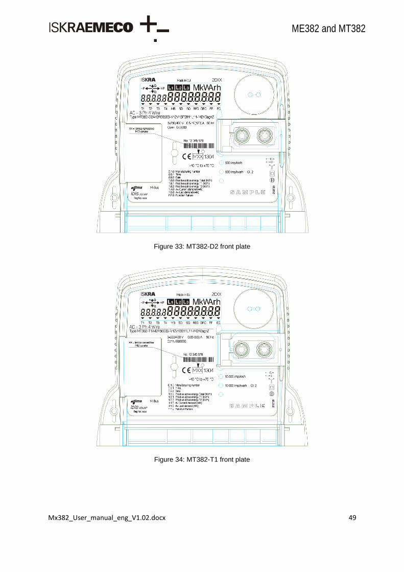
Mx382_User_manual_eng_V1.02.docx 49
ME382 and MT382
Figure 33: MT382-D2 front plate
Figure 34: MT382-T1 front plate

Mx382_User_manual_eng_V1.02.docx 50
ME382 and MT382
4.4. Console keys
Main features on the meters console are LCD, two LED‟s and two keys. Every meter has them integrated.
4.4.1 LCD
The seven-segment liquid crystal display (LCD) complies with the VDEW requirements.
Figure 35: Full Mx382 LCD – display fields
Item Description
1 Alphanumeric field 1 – Small five 7-segment digits – OBIS identification code presentation
2 Alphanumeric field 2 – Large eight 7-segment digits – Data value presentation.
3 Power flow direction cursors
4 Voltage presence by phases indicators
5 Physical unit field of the currently displayed data
6 Cursors
4.4.1.1. Alphanumeric fields
Alphanumeric field 1 is used for presentation the OBIS identification codes of the displayed data (in
accordance with DIN 43863-3). The hight of characters is 6mm and width is 3mm.
Alphanumeric field 2 is used for presentation the data value. The hight of characters is 8mm and width
is 4mm.
4.4.1.2. Display test state
In display test state all segments are displayed.
Figure 35 shows the display in the test state.
4.4.1.3. Power flow direction cursors
There are four power flow direction cursors on the display:
Positive reactive power flow (+Q),
Positive active power flow (+P),

Mx382_User_manual_eng_V1.02.docx 51
ME382 and MT382
Negative reactive power flow (-Q),
Negative active power flow (-P).
4.4.1.4. Phase indicators
Segments L1, L2 and L3 show indicated phases on meter. Blinking segments represents wrong phase
sequence connection.
4.4.1.5. Physical unit field
Physical unit field shows units of currently displayed data.
4.4.1.6. Characters
Characters, which can be represented on a display, are listed below. Alphanumeric fields have a 7-
segment display shape. There are also some additional dot fields. Alphanumeric characters are used
to display values, tariff name, consumer message, signatures, etc.
Figure 36: Characters represented on a display
Available characters, which can be represented on a display:
“-”, “ ”
“0”, “1”, “2”, “3”, “4”, “5”, “6”, “7”, “8”, “9”,
“A”, “B”, “C”, “D”, “E”, “F”, “G”, “H”, “I”, “J”, “L”, “N”, “O”, “P”, “R”, “S”, “T”, “U”, “Y”, “Z”
(Letters B, D, I, N, O, R, T, will be displayed as b, d, i, n, o, r, t)
“a”, “b”, ”c”, “d”, “e”, “f”, “g”, “h”, “i”, “j”, “l”, “n”, “o”, “p”, “r”, “s”, “t”, “u”, “y”, “z”
(Letters a, c, e, f, g, j, l, p, s, y, z will be displayed as A, C, E, F, G, J, L, P, S, Y. Z)

Mx382_User_manual_eng_V1.02.docx 52
ME382 and MT382
4.4.1.7. Cursors
On the front plate below the LCD display meter has laser printed markings that belong to the cursors
on the LCD. The cursor shows the state of certain function that it represents e.g. tariff, registration,
disconnector status, meter fault...
Flags (cursors) in the lower bar readout have the following meaning (from left to right):
Flag Name Not displayed Displayed Blinking 1 T1/5 Active first tariff Active fifth tariff / param switch off *
2 T2/6 Active second tariff Active sixth tariff / param switch off *
3 T3/7 Active third tariff Active seventh tariff / param switch off *
4 T4/8 Active fourth tariff Active eighth tariff / param switch off *
5 MB No M-Bus device installed At least one M-Bus device
installed
6 SD Disconnector inactive
(connection)
Disconnector active
(disconnection)
7 SQ GSM signal quality below the low lower limit (defined by object 0-0:128.20.11
GSM signal quality above the
high lower limit (defined by
object 0-0:128.20.12
GSM signal quality between the both
lower limits
8 REG Meter not logged in the
GSM network
Meter logged in the GSM
network with installation call
made or not enabled
GSM/GPRS modem registered but
installation call wasn‟t made
9 DRO Meter data down-loading is
in progress
Data package is present in the AMR
communication network
10 FF No fault “Fatal“ fault
11 SET Normal operation mode
EC Emergency Credit active Emergency Credit threshold limit expired
Table 24: LCD cursors
Figure 37: LCD cursors
4.4.1.8. Display format
Two objects are used to configure format for energy and demand values on display. Up to eight digits
are used to display a value and up to three of them can be used for decimal precision. On display
active energy is represented in (kWh), reactive energy in (kvar), apparent energy in (var) and demand
in (kW).
T1 T2 SD DRO FF EC T3 T4 DLC
Flag is on
Flag is off
Flag is blinking
T1 T2 SD SQ REG DRO FF EC
LEGEND
METER FLAGS (DLC)
METER FLAGS (GSM)
MB
MBT3 T4 T5 T6 T7 T8
T5 T6 T7 T8
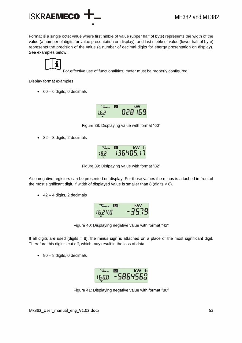
Mx382_User_manual_eng_V1.02.docx 53
ME382 and MT382
Format is a single octet value where first nibble of value (upper half of byte) represents the width of the
value (a number of digits for value presentation on display), and last nibble of value (lower half of byte)
represents the precision of the value (a number of decimal digits for energy presentation on display).
See examples below.
For effective use of functionalities, meter must be properly configured.
Display format examples:
60 – 6 digits, 0 decimals
Figure 38: Displaying value with format “60“
82 – 8 digits, 2 decimals
Figure 39: Dislpaying value with format “82“
Also negative registers can be presented on display. For those values the minus is attached in front of
the most significant digit, if width of displayed value is smaller than 8 (digits < 8).
42 – 4 digits, 2 decimals
Figure 40: Displaying negative value with format “42“
If all digits are used (digits = 8), the minus sign is attached on a place of the most significant digit.
Therefore this digit is cut off, which may result in the loss of data.
80 – 8 digits, 0 decimals
Figure 41: Displaying negative value with format “80“

Mx382_User_manual_eng_V1.02.docx 54
ME382 and MT382
If configured format width is smaller than register value it results in the loss of data on display.
42 – 4 digits, 2 decimals.
register value: -35790 W……….displayed value is OK.
register value: -1435790 W……displayed value is limited to format width (two most significant digits are missing).
Figure 42: Displaying negative value with improper format “42“ according to register value
The objects, that are not intended to show on the display, will not be displayed, if they are included in
General display readout list (0-0:21.0.1) or in Alternate display readout list (0-0:21.0.2). The message
code Error 11 (Ident format failed) will be displayed instead.
Figure 43: Ident format failed message
4.4.1.9. OBIS name on display
There are 5 digits reserved for OBIS name presentation on the left side of the display. OBIS name is
always displayed from the first digit on the left.
In general there are two types of OBIS name format:
Short OBIS name format: C.D.E
Full OBIS name format: A.B.C.D.E
For presentation on the display the short OBIS name format is used: C.D.E. There are some
exceptions, when extended OBIS name is displayed:
A.B.C.D.E format is used for presentation of the following objects: • Core identification (1.0.0.2.0) • Module identification (1.1.0.2.0) • Core signature (1.0.0.2.8) • Module signature (1.1.0.2.8)
B.C.D.E format is used for presentation of the objects with field B ≠ 0.
Up to 5 characters of OBIS name can be displayed. There are some abbreviation characters used for
the specific multi-character fields of OBIS name:
Multi-character field Abbreviation character
96 C
97 F
98 L
99 P
128 U
Table 25: OBIS name abbreviation characters

Mx382_User_manual_eng_V1.02.docx 55
ME382 and MT382
4.4.1.10. Error codes on display
In certain cases an error message can appear on display. The error codes that can be seen on display
are listed in a table below:
Error code Error description
Error 11 Ident format failed
Error 23 Ident not existing
Error 31 Value format failed
Table 26: Error codes on display
4.4.1.11. Console period
Three console period timings are defined in meter which are all fixed and cannot be changed:
exit period after last pressed key (default is 120s),
auto scroll period (default is 10s),
backlight lit time after pressed key (default is 30s).
4.4.1.12. Horizontal scroll
Presentation of strings on display is performed with horizontal scroll, if the size of string is larger than
the size of alphanumeric field for value on display (8 characters). Horizontal scroll shift period is one
second. When the horizontal scroll is performed in Auto scroll mode, the auto scroll period (10s) is
extended until end of the string is reached.
4.4.1.13. Tariff on display
Active tariff is indicated on display by an appropriate cursor, as it is defined above. For details see
Chapter 4.4.1.7.
Active tariff can also be displayed with a dedicated name. For this purpose the Currently active energy
tariff object (0-0:96.14.0) needs to be set in:
General display readout list (0-0:21.0.1) for use in Auto-scroll mode sequence or
Alternate display readout list (0-0:21.0.2) for use in Manual-scroll mode sequence.
Active tariff name can be constructed with the characters that are supported for presentation on
display.
Limitations:
Maximum number of characters used for tariff name is 8. If more than 8 characters are used, the meter will reject the entry.
Characters that are not supported for presentation on LCD, will be shown as blank segments.
Value of Currently active energy tariff object (0-0:96.14.0) is seen in hex format.
Active tariff name has to be set in dedicated objects with setting file (.ncs): • Register activation object (0-0:14.0.1) – Active mask. • Tariffication script table object (0-0:10.0.100) – Parameter.
Active tariff name has to be set in ASCII format to be presented on display. Otherwise the value is ignored for presentation on display and is shown as blank digits.

Mx382_User_manual_eng_V1.02.docx 56
ME382 and MT382
Default value of the Active tariff name (0001, 0002, …, 0008) is not set in ASCII format,therefore are not suitable for presentation on display.
Figure 44: Tariff on display
For effective use of functionalities, meter must be properly configured.
4.4.1.14. Signature on display
Active firmware module signature object: 1-1:0.2.8,
Active firmware core signature object: 1-0:0.2.8,
Full OBIS code presentation is used for Active firmware module/core signature objects.
Firmware module/core signature presentation on display is performed with horizontal scroll, ifthe size of signature string is larger than the size of alphanumeric field for value on display (8characters).
Horizontal scroll shift period is one second.
Figure 45: Signature on display
4.4.2 Metrological LEDs
The meter is provided with two red colored LEDs on the front plate. They are intended for checking the meter accuracy. Impulse constant depends on the meter version.
MT382
upper LED indicates active energy flow,
middle LED indicates reactive / apparent energy flow.
ME382
right LED indicates active energy flow,
left LED indicates reactive / apparent energy flow.
In normal meter operation mode LEDs emit pulses with frequency that is proportional to the measured power and is intended for the meter calibration and testing. The LEDs are turned-on and glows steadily if load is lower than the meter starting current.
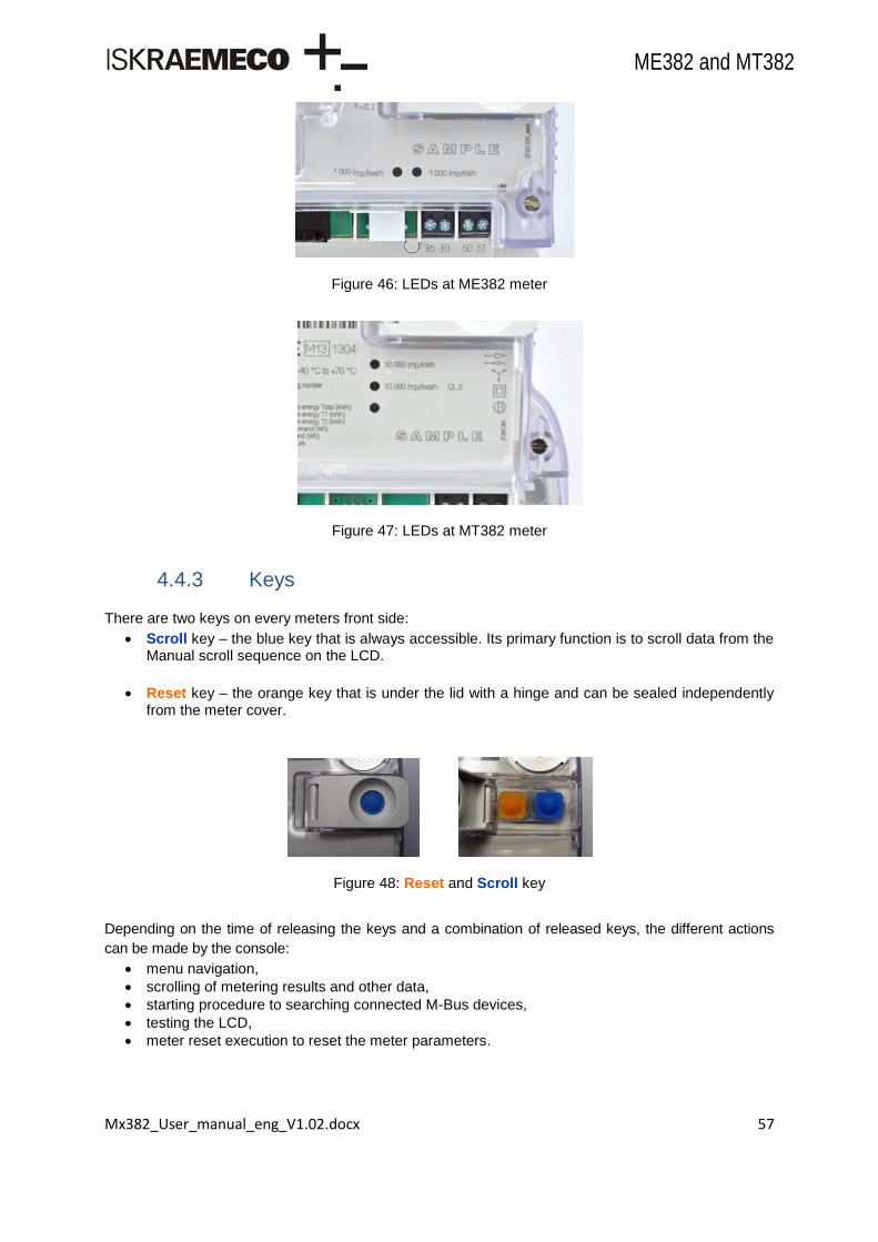
Mx382_User_manual_eng_V1.02.docx 57
ME382 and MT382
Figure 46: LEDs at ME382 meter
Figure 47: LEDs at MT382 meter
4.4.3 Keys
There are two keys on every meters front side:
Scroll key – the blue key that is always accessible. Its primary function is to scroll data from the Manual scroll sequence on the LCD.
Reset key – the orange key that is under the lid with a hinge and can be sealed independently from the meter cover.
Figure 48: Reset and Scroll key
Depending on the time of releasing the keys and a combination of released keys, the different actions
can be made by the console:
menu navigation,
scrolling of metering results and other data,
starting procedure to searching connected M-Bus devices,
testing the LCD,
meter reset execution to reset the meter parameters.
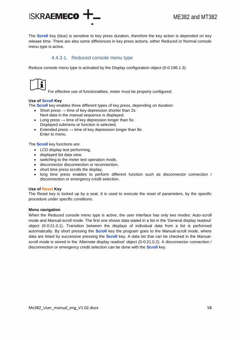
Mx382_User_manual_eng_V1.02.docx 58
ME382 and MT382
The Scroll key (blue) is sensitive to key press duration, therefore the key action is depended on key
release time. There are also some differences in key press actions, either Reduced or Normal console
menu type is active.
4.4.3.1. Reduced console menu type
Reduce console menu type is activated by the Display configuration object (0-0:196.1.3).
For effective use of functionalities, meter must be properly configured. Use of Scroll Key The Scroll key enables three different types of key press, depending on duration:
Short press → time of key depression shorter than 2s: Next data in the manual sequence is displayed.
Long press → time of key depression longer than 5s: Displayed submenu or function is selected,
Extended press → time of key depression longer than 8s: Enter to menu.
The Scroll key functions are:
LCD display test performing,
displayed list data view,
switching to the meter test operation mode,
disconnector disconnection or reconnection,
short time press scrolls the display,
long time press enables to perform different function such as disconnector connection / disconnection or emergency credit selection.
Use of Reset Key
The Reset key is locked up by a seal. It is used to execute the reset of parameters, by the specific
procedure under specific conditions.
Menu navigation
When the Reduced console menu type is active, the user interface has only two modes: Auto-scroll
mode and Manual-scroll mode. The first one shows data stated in a list in the 'General display readout'
object (0-0:21.0.1). Transition between the displays of individual data from a list is performed
automatically. By short pressing the Scroll key the program goes to the Manual-scroll mode, where
data are listed by successive pressing the Scroll key. A data list that can be checked in the Manual-
scroll mode is stored in the 'Alternate display readout' object (0-0:21.0.2). A disconnector connection /
disconnection or emergency credit selection can be done with the Scroll key.

Mx382_User_manual_eng_V1.02.docx 59
ME382 and MT382
Figure 49: Menu navigation diagram for reduced console
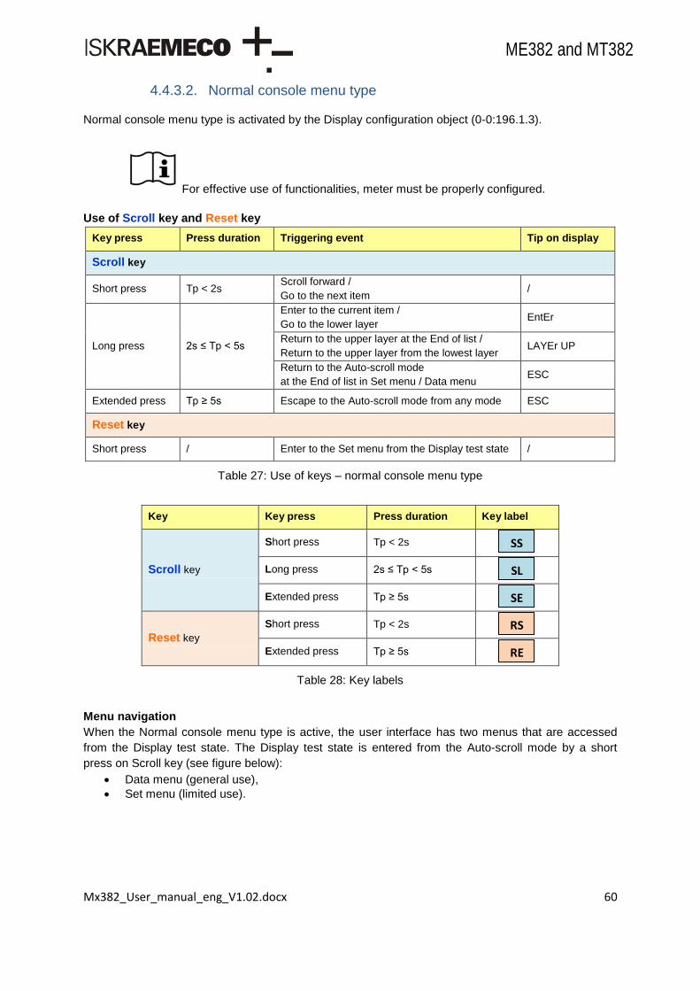
Mx382_User_manual_eng_V1.02.docx 60
ME382 and MT382
4.4.3.2. Normal console menu type
Normal console menu type is activated by the Display configuration object (0-0:196.1.3).
For effective use of functionalities, meter must be properly configured.
Use of Scroll key and Reset key
Key press Press duration Triggering event Tip on display
Scroll key
Short press Tp < 2s Scroll forward /
Go to the next item /
Long press 2s ≤ Tp < 5s
Enter to the current item /
Go to the lower layer EntEr
Return to the upper layer at the End of list /
Return to the upper layer from the lowest layer LAYEr UP
Return to the Auto-scroll mode
at the End of list in Set menu / Data menu ESC
Extended press Tp ≥ 5s Escape to the Auto-scroll mode from any mode ESC
Reset key
Short press / Enter to the Set menu from the Display test state /
Table 27: Use of keys – normal console menu type
Key Key press Press duration Key label
Scroll key
Short press Tp < 2s
Long press 2s ≤ Tp < 5s
Extended press Tp ≥ 5s
Reset key
Short press Tp < 2s
Extended press Tp ≥ 5s
Table 28: Key labels
Menu navigation
When the Normal console menu type is active, the user interface has two menus that are accessed
from the Display test state. The Display test state is entered from the Auto-scroll mode by a short
press on Scroll key (see figure below):
Data menu (general use),
Set menu (limited use).
RE
FS
RS
FS
SE
SL
FS
SS
FS

Mx382_User_manual_eng_V1.02.docx 61
ME382 and MT382
Figure 50: Entering the Data/Set menu
4.4.3.3. Data menu
Data menu is accessed from the Display test state by a short press on Scroll key. There are several
items supported for presentation in Data menu on display. The first item is Manual-scroll mode (Std
data). It is fixed and can not be disabled. Other items are optional and can be configured by the
Display configuration object (0-0:196.1.3). In Data menu the following items are listed in order:
Std data – Manual-scroll mode,
P.01 – Load profile with period 1 (optional),
P.02 – Load profile with period 2 (optional),
End – end of list.
Figure 51: Data menu navigation
4.4.3.4. Set menu
Set menu is accessed from the Display test state by a short press on Reset key, which is protected
with a seal. In Set menu the following items are listed in order:
Reset – Reset mode – reset of parameters, by the specific procedure under specific conditions,
Lcd test – Lcd test mode – display unit test,
End – end of list.

Mx382_User_manual_eng_V1.02.docx 62
ME382 and MT382
Figure 52: Set menu navigation
4.4.3.5. Auto-scroll mode
Auto-Scroll mode is implemented in the following way:
Auto-scroll mode is general meter mode, where the items listed in General display readout object (0-0:21.0.1) are cyclically displayed on LCD.
Auto-scroll time is a compile-time parameter and is set to 10 seconds.
General display readout object (0-0:21.0.1) is an instance of COSEM Profile Generic class, where only
Capture Objects attribute is relevant (or other attributes are not used).
For effective use of functionalities, meter must be properly configured.
4.4.3.6. Manual scroll mode
Manual-Scroll mode is implemented in the following way:
Manual-scroll mode is used for manual data review on display.
Displayed items are listed in Manual-scroll mode sequence list, defined by Alternate display readout object (0-0:21.0.2).
Manual-scroll mode is accessible from the Data menu by a long press on Scroll key at the Std data item, when tip Enter is shown. Then the first item from the sequence list is displayed.
The next item from the sequence list is displayed by a short press on Scroll key.
At the end of sequence the End notice is displayed.
Return to the Data menu is performed by a long press on Scroll key, when tip Layer up is shown.
Escape in Auto-scroll mode is performed by an extended press on Scroll key, when tip Esc is shown.
Alternate display readout object (0-0:21.0.2) is an instance of COSEM Profile Generic class, where
only Capture Objects attribute is relevant (or other attributes are no used).
For effective use of functionalities, meter must be properly configured.

Mx382_User_manual_eng_V1.02.docx 63
ME382 and MT382
Figure 53: Manual-scroll mode navigation
4.4.3.7. Load profile on display (P.01, P.02)
Presentation of Load profile on display is optional and can be enabled by a bit–parameter in the
Display configuration object (0-0:196.1.3). Load profile presentation is accessible from the Data menu
by a long press on Scroll key at the P.01 / P.02 item, when tip Enter is shown. There are two types of
Load profile supported:
P.01 – Load profile with period 1,
P.02 – Load profile with period 2.
Load profile presentation on display follows VDEW specifications in general. Load profile is presented
on display in three layers:
layer DATE (upper layer),
layer TIME (middle layer),
layer ATTR (attribute) (lower layer).
For effective use of functionalities, meter must be properly configured.

Mx382_User_manual_eng_V1.02.docx 64
ME382 and MT382
Figure 54: Load profile on display navigation
4.4.3.8. LCD test mode
LCD test mode is used for testing purposes to perform LCD unit test. LCD test mode is accessed from
the Set menu by a long press on Scroll key at the Lcd test item, when tip Enter is shown.
There are four LCD test conditions (all, odd, even, none segments), which can be scrolled by a
short press on Scroll key.
Return to the Set menu is performed, when all LCD test conditions are scrolled.
It is also possible to return to the Set menu from any LCD test condition, by a long press on Scroll key, when tip Layer up is shown.
Escape into the Auto-scroll mode is performed by an extended press on Scroll key, when tip Esc is shown.
Legend:
YY → Year hh → hours
MM → Month mm → minutes
DD → Day X → Load profile period 1 or 2
Display forms by layers:
P.0X YY.MM.DD P.0X DD.hh:mm C.10.1 1
1.8.0 000000
…
Layer DATE
SS
Item 1
Item 2
…
End
Layer TIME
SS
Item 1
Item 2
…
End
Item 1
Item 2
…
End
Layer ATTR
SS
Enter
SL
Layer up
SL
Enter
SL
Layer up
SL
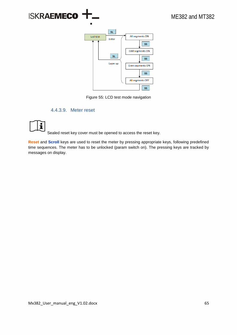
Mx382_User_manual_eng_V1.02.docx 65
ME382 and MT382
Figure 55: LCD test mode navigation
4.4.3.9. Meter reset
Sealed reset key cover must be opened to access the reset key.
Reset and Scroll keys are used to reset the meter by pressing appropriate keys, following predefined
time sequences. The meter has to be unlocked (param switch on). The pressing keys are tracked by
messages on display.
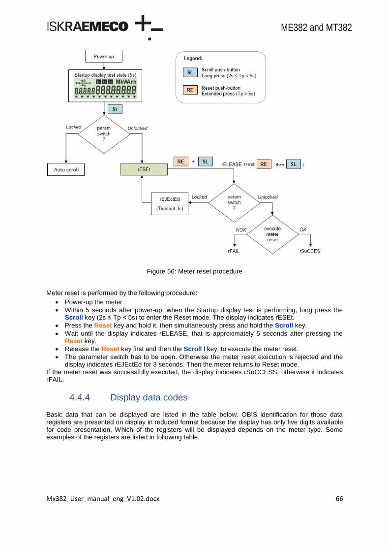
Mx382_User_manual_eng_V1.02.docx 66
ME382 and MT382
Figure 56: Meter reset procedure
Meter reset is performed by the following procedure:
Power-up the meter.
Within 5 seconds after power-up, when the Startup display test is performing, long press the Scroll key (2s ≤ Tp < 5s) to enter the Reset mode. The display indicates rESEt.
Press the Reset key and hold it, then simultaneously press and hold the Scroll key.
Wait until the display indicates rELEASE, that is approximately 5 seconds after pressing the Reset key.
Release the Reset key first and then the Scroll l key, to execute the meter reset.
The parameter switch has to be open. Otherwise the meter reset execution is rejected and the display indicates rEJEctEd for 3 seconds. Then the meter returns to Reset mode.
If the meter reset was successfully executed, the display indicates rSuCCESS, otherwise it indicates rFAIL.
4.4.4 Display data codes
Basic data that can be displayed are listed in the table below. OBIS identification for those data registers are presented on display in reduced format because the display has only five digits available for code presentation. Which of the registers will be displayed depends on the meter type. Some examples of the registers are listed in following table.

Mx382_User_manual_eng_V1.02.docx 67
ME382 and MT382
Code Data description
0.0.0 Meter serial number
C.1.0 Meter manufacturer number
0.9.1 Time
0.9.2 Date
1.8.0 Total imported active energy (A+)
1.8.1 Imported active energy in the 1st tariff (T1)
1.8.2 Imported active energy in the 2nd
tariff (T2)
1.8.3 Imported active energy in the 3rd tariff (T3)
1.8.4 Imported active energy in the 4th tariff (T4)
15.8.0 Total absolute active energy |A|
15.8.1 Absolute active energy in the 1st tariff |T1|
15.8.2 Absolute active energy in the 2nd
tariff |T2|
15.8.3 Absolute active energy in the 3rd tariff |T3|
15.8.4 Absolute active energy in the 4th tariff |T4|
2.8.0 Total exported active energy (A-)
2.8.1 Exported active energy in the 1st tariff (T1)
2.8.2 Exported active energy in the 2nd
tariff (T2)
2.8.3 Exported active energy in the 3rd tariff (T3)
2.8.4 Exported active energy in the 4th tariff (T4)
1.6.0 Total A+ imported maximum demand
2.6.0 Total A- exported maximum demand
F.F.0 Meter fatal error
Table 29: Display register codes
For effective use of functionalities, meter must be properly configured.
4.5. Voltage bridge
A sliding voltage bridge (only on MT382 direct connected meters) is intended for fast and simple
separation of meter current and voltage circuit used for calibration or accuracy testing. A special slider
is built in each phase of the connection terminal. It can be shifted up and down with a screwdriver.
When a voltage bridge is in “0” position, it means that the voltage part is separated from the current
part. During the meter testing and calibration the sliding voltage bridges should be in position “0”.
When a voltage bridge is in position “1” the voltage part is not separated from the current part. During
the normal meter operation the potential links should be closed (position “1”). Upon request, the
potential links can be built under the meter cover.
Figure 57: Sliding voltage bridge
Position 0
Position 1

Mx382_User_manual_eng_V1.02.docx 68
ME382 and MT382
5. Mx382 meter constituent parts
5.1. Mx382 meter type designation
ME382-D1A42R56S63-V12V13P1B11L11-M2K0agnZ
MT382-D2A42R56S63-I4V12V13P0B1
ME Single-phase electronic meter
MT Three-phase three-system electronic meter
382 With built-in GSM/GPRS modem
- Separator
D1 Terminal block: Imax=85A
D2 Terminal block: Imax=120A
D3 Terminal block: Imax=100A
T1 Terminal block up to 6 A
A4 Active energy measurement, accuracy class 1
A5 Active energy measurement, accuracy class 2
1 Energy measurement in one direction
2 Energy measurement in two directions
4 Absolute energy measurement
R5 Reactive energy measurement, accuracy cl. 2
R6 Reactive energy measurement, accuracy cl. 3
1 Energy measurement in one direction
2 Energy measurement in two directions
6 Energy measurement in all 4 quadrants in both directions
S5 Apparent energy measurement, accuracy cl. 2
S6 Apparent energy measurement, accuracy cl. 3
3 Energy calculated as SQR (P^2+Q^2)
- Separator
I Internal auxiliary power supply
4 Ultra capacitor
V Control inputs
1 No. of inputs
2 High voltage control - 230V
3 No voltage control - transformer
P Integrated disconnector
0 Three phase disconnection - external
1 One phase disconnection - internal
B High voltage output – relay type
1 One relay contact output
1 Relay contact output with make contact
L High voltage output – OptoMOS type
1 One control output
1 Control output with make contact
- Separator
M Internal clock
2 Back-up power supply – super capacitor
3 Back-up power supply – battery

Mx382_User_manual_eng_V1.02.docx 69
ME382 and MT382
K Communication interface
0 Optical interface (IEC62056-21)
a GSM/GPRS communication
g M-Bus comm. interface – master
n P1 port
Z Load profile
Table 30: Meter type designation
5.2. Inputs and outputs
Every meter has built in input/output terminals. They are driven through the meter firmware functionality and can have different shared functions on the same pin through the specific configuration. Some functions (for hardware reasons) are not available on all meters. Functions can be used to operate with:
Relay output,
OptoMOS output,
Outputs for active disconnector (SD),
Alarm input,
External key input / No voltage external key input.
For effective use of functionalities, meter must be properly configured.
5.2.1 Relay output - load
Load Control registers are used to configure bi-stable relay output with maximum capability of 6A at
250V. Load control terminals are:
34 – Relay output,
35 – Common.
Figure 58: Load control terminal
This output can also be triggered via tariff program. Tariffication script table needs to be configured
accordingly.
Note!
When power-down occurs and relay state is on with power on delay mode enabled,
power-up will cause the relay to switch off for the time set in load control power on
delay before it switches back to on state!

Mx382_User_manual_eng_V1.02.docx 70
ME382 and MT382
5.2.1.1. Load control delay mode
With Load Control Mode different types of switching can be set. Available mode options are:
(0) – Normal,
(1) – Switch on Delayed,
(2) – Switch on Random Delayed,
(3) – Switch On Delayed with Power on Delay,
(4) – Switch On Delayed with Power on Random Delay,
(5) – Switch On Random Delayed with Power on Delay,
(6) – Switch On Random Delayed with Power on Random Delay.
5.2.1.2. Load control power on delay
This register defines relay power up delay time, before it is switched on. Delay time is set in seconds.
Used for grid power balance, when power returns.
5.2.1.3. Load control switch on delay
This register defines relay switch on delay time, before relay is switched on. Delay time is set in
seconds. Used for grid power balance on tariff action relay on.
5.2.1.4. Load management relay control 1
This object controls relay state machine. By default outputs are in disconnected state.
Figure 59: Relay state transitions
Mode Description
0 None. The disconnect control object is always in „connected‟ state
2 Disconnection:
Remote (b, c)
Local (g)
Reconnection: Remote (a)
4 Disconnection:
Remote (b, c)
Local (g)
Reconnection: Remote (a)
5 Disconnection: Remote (b, c)

Mx382_User_manual_eng_V1.02.docx 71
ME382 and MT382
Local (g)
Reconnection: Remote (d) local (h)
6
Disconnection: Remote (b, c)
Local (g)
Reconnection: Remote (d) Local (h)
Table 31: Disconnect modes
Note! To perform the switchover, methods described below should be executed (remotely or locally). Manual transitions are not possible on relay object.
5.2.2 OptoMOS output - service
Service Control registers are used to configure OptoMOS output with maximum capability of 0,1A at
250V. Service control terminals are:
33 – OptoMOS output,
35 – Common.
Figure 60: Service control terminal
To configure service control function an object of COSEM Class Data is introduced. Service Control
Functionality object define a function of service control. If metropulse output function is selected other
service control parameters have no influence on behavior of OptoMOS output.
This output can also be triggered via tariff program. Tariffication script table needs to be configured
accordingly.
5.2.2.1. Service control functionality
With Service Control Functionality different types of functions can be selected. Available function
options are:
(0) – Switching,
(1) – Metropulse output (see Chapter 3.6.2),
(otherwise) – Reserved.
5.2.2.2. Service control delay mode
With Service Control Mode different types of switching can be set. Available mode options are:
(0) – Normal,

Mx382_User_manual_eng_V1.02.docx 72
ME382 and MT382
(1) – Switch on Delayed,
(2) – Switch on Random Delayed,
(3) – Switch On Delayed with Power on Delay,
(4) – Switch On Delayed with Power on Random Delay,
(5) – Switch On Random Delayed with Power on Delay,
(6) – Switch On Random Delayed with Power on Random Delay.
5.2.2.3. Service control power on delay
With this register OptoMOS switch delay at power up can be set and is used when OptoMOS state
should be switched on. Delay time is set in seconds.
5.2.2.4. Service control switch on delay
With this register relay switch delay at state switch can be set and is used when OptoMOS state
should be switched on. Delay time is set in seconds.
5.2.2.5. Load management relay control 2
This object controls the connection and disconnection of the relay. Switching of either of the outputs can be controlled via build in time of use by setting the switching times for corresponding tariffs. See also TOU settings. By default outputs are active when the low tariff is active.
For effective use of functionalities, meter must be properly configured.
5.2.3 Inputs
Inputs are simple passive inputs with capability to detect a presence of voltage level on dedicated
terminals. There is one variation of input type:
High Voltage 230V AC inputs.
Up to two inputs can be used on the meter, however only one type can be chosen (low voltage or high
voltage input). Inputs can be configured for alarm or external key use only. To be able to use inputs,
I/O Control register needs to be configured according to desired needs. There is a maximum of four
input terminals (two functional inputs) intended for alarm or external key function use. Terminal labels
are the same for all system meter types.
Terminals are labeled as:
85 – Common,
80 – Alarm input 2,
50 – Passive External key,
51 – Passive External key.

Mx382_User_manual_eng_V1.02.docx 73
ME382 and MT382
Figure 61: Mx382 input terminals
5.2.4 Active SD outputs
This output is low voltage transistor output. There are three output pins on the terminal block which
serve these outputs (only on MT382 meters) and are intended for disconnector.
For more info on disconnector see Chapter 6.18.
5.2.5 Input/output status
This is read only information of I/O status. I/O Status is represented as a decimal number which is a result of all input or output function statuses. Each input or output function has its own designated bit in 16 bit input or output register. This bit can be enabled (logical 1) or disabled (logical 0). According to that, HEX number is a result of the whole binary register word. Not all bits in the register are used and some are reserved for future functions.
5.2.5.1. State of the input control signals
Input control status register (0-0:96.3.1) includes this input function bits:
Bit HEX (when bit set) Bit name Remarks
0-5
6 0x0040 ALARM IN 1 20/15 or 50/51
7 0x0080 ALARM IN 2 85/80
8-12
13 0x2000 SCROLL KEY Key pressed
14 0x4000 RESET KEY Key pressed
15 0x8000 PARAM LOCK SWITCH Locked
Table 32: Input state control register
5.2.5.2. State of the output control signals
Output control status register (0-0:96.3.2) includes this output function bits:
x x x x x x x x x x x x x x x x
Bit 15 . . . . . . . . . . . . 0

Mx382_User_manual_eng_V1.02.docx 74
ME382 and MT382
For 1-phase meter:
Bit HEX (when bit set) Bit name Remarks
0 0x0001 RELAY OUTPUT Relay ON
1 0x0002 RELAY OUTPUT Relay OFF
2-3
4 0x0010 BREAKER OUTPUT Breaker ON
5 0x0020 BREAKER OUTPUT Breaker OFF
6-7
8 0x0100 SERVICE OUTPUT OptoMOS ON
9-15
Table 33: Output state control register
For 3-phase meter:
Bit HEX (when bit set) Bit name Remarks
0 0x0001 RELAY OUTPUT Relay ON
1 0x0002 RELAY OUTPUT Relay OFF
2-3
4 0x0010 BREAKER OUTPUT Breaker OFF
5 0x0020 BREAKER OUTPUT Breaker ON
6-7
8 0x0100 SERVICE OUTPUT OptoMOS ON
9-15
Table 34: Output state control register
5.3. Real time clock
Depending on customer needs meters have three options of power storage devices which guaranty
operation of Real Time Clock and Tamper functionality during power loss.
Option 1 : One SuperCap
Enables operation for 7 days, when meter is previously charged for 24h continuosly. Data is valid for
ambient temperature 25°C.
Option 2 : Two SuperCaps
Enables operation for 20 days, when meter is previously charged for 168h continuosly. Data is valid
for ambient temperature 25°C.
Option 3 : Lithium battery
Enables operation of RTC and Tamper for longer periods. Battery has 20 years life time and provides
enough energy to enable 10 years operation.
For effective use of functionalities, meter must be properly configured.
Clock object consists of several time/date related attributes. These attributes are divided into:
Local time/date,
Time zone,
Daylight savings time (DST).

Mx382_User_manual_eng_V1.02.docx 75
ME382 and MT382
5.3.1 Time
Contains the meter‟s local date and time, its deviation to UTC and the status.
Figure 62: Time and Date Data Format
Time zone attribute holds the deviation of local, normal time to UTC in minutes.
5.3.2 Status
The status is equal to the status read in time.
Clock status shows if DST is currently active or not
128 (DST is currently active – current time/date is in DST boundaries),
0 (DST is currently not active – current time/date is outside DST boundaries).
5.3.3 Daylight Savings
Daylight saving begin/end defines the local switch date and time when the local time has to be
deviated from the normal time. DST start and end date needs to be entered where specific values for
“day in a week” are:
FD = 2nd last day of month,
FE = last day of month,
FF = not specified.
For repetitive dates, the unused parts must be set to “not specified”.
Daylight savings deviation contains the number of minutes by which the deviation in generalized time must be corrected at daylight savings begin. Deviation (in minutes shows the difference from GMT time and clock status active/inactive DST. Deviation range of up to ± 120 min.
Daylight savings enabled To use DST, DST needs to be enabled with start and end date set also. DST Status can be:
TRUE = DST enabled - (1),
FALSE = DST disabled - (0).
5.3.4 Local time and date
These two objects are part of clock object and show only date or time. Date and time are represented on the meter display like this:
Time:hh:mm:ss (hours:minutes:seconds),
Date:yy.mm.dd (year.month.day),
OCTET1 OCTET2 OCTET3 OCTET4 OCTET5 OCTET6 OCTET7 OCTET8 OCTET9 OCTET10 OCTET11 OCTET12
YYYY MM DD WD hh mm ss hd dddd CS
Year Month Day Week Day
Hour Minute Second Hund-redths
Deviation Clock Status
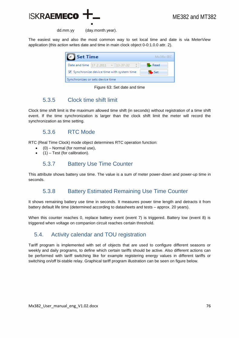
Mx382_User_manual_eng_V1.02.docx 76
ME382 and MT382
dd.mm.yy (day.month.year). The easiest way and also the most common way to set local time and date is via MeterView
application (this action writes date and time in main clock object 0-0:1.0.0 attr. 2).
Figure 63: Set date and time
5.3.5 Clock time shift limit
Clock time shift limit is the maximum allowed time shift (in seconds) without registration of a time shift
event. If the time synchronization is larger than the clock shift limit the meter will record the
synchronization as time setting.
5.3.6 RTC Mode
RTC (Real Time Clock) mode object determines RTC operation function:
(0) – Normal (for normal use),
(1) – Test (for calibration).
5.3.7 Battery Use Time Counter
This attribute shows battery use time. The value is a sum of meter power-down and power-up time in
seconds.
5.3.8 Battery Estimated Remaining Use Time Counter
It shows remaining battery use time in seconds. It measures power time length and detracts it from
battery default life time (determined according to datasheets and tests – approx. 20 years).
When this counter reaches 0, replace battery event (event 7) is triggered. Battery low (event 8) is
triggered when voltage on companion circuit reaches certain threshold.
5.4. Activity calendar and TOU registration
Tariff program is implemented with set of objects that are used to configure different seasons or
weekly and daily programs, to define which certain tariffs should be active. Also different actions can
be performed with tariff switching like for example registering energy values in different tariffs or
switching on/off bi-stable relay. Graphical tariff program illustration can be seen on figure below.

Mx382_User_manual_eng_V1.02.docx 77
ME382 and MT382
Figure 64: Graphical tariff program
TOU capabilities:
Up to 8 tariffs,
Up to 8 masks for configuring different combinations of tariff registers,
Up to 12 seasons tariff programs,
Up to 12 week tariff programs,
Up to 12 day tariff programs,
Up to 16 actions per day tariff program,
Up 64 special day date definitions.
Possible ways of tariff switching are:
Separate energy and demand tariff switching,
Tariff switching via internal RTC (by IEC 61038),
5.4.1 Tariff program
Tariff program configures different seasons or weekly and daily programs to define, which certain
tariffs should be active. Different actions can be performed with tariff switching like registering energy
values in different tariffs or switching on and off the bi-stable relay.
For effective use of functionalities, meter must be properly configured.
5.4.2 Activity calendar
Activity calendar is time of use (TOU) object for tariff control. It allows modeling and handling of
various tariff structures in the meter.
To handle different tariff structures an instance of the COSEM class “Activity calendar” is used. It is
used to store energy and demand according to tariff rate schedule.
It is a definition of scheduled actions inside the meter, which follow the classical way of calendar based schedules by defining seasons, weeks and days.
After a power failure, only the “last action” missed from “Activity calendar” is executed (delayed). This is to ensure proper tariff after power up.

Mx382_User_manual_eng_V1.02.docx 78
ME382 and MT382
Activity calendar consists of two calendars, active and passive, and an attribute for activation of passive calendar. Changes can be made only to passive calendar and then activated to become active calendar. Each calendar has following attributes:
Calendar name,
Season profile,
Week profile table,
Day profile table.
5.4.2.1. Calendar Name
Calendar name typically contains an identifier, which describes calendar parameter set. With Calendar name the calendar can be identified.
5.4.2.2. Season Profile
The season table can be divided into 12 periods (seasons), during which different week tables are
applicable. FF value is used for not specified fields. Season profile consists of:
Season name,
Season start date & time,
Week name.
5.4.2.3. Week Profile Table
The week table determines the day profile table applicable for particular week. 12 week tables are
available – one week profile per season. Since week tables are only divided into days, Monday to
Sunday without time data, they are repeated every week while they are valid according to season
profile. Value FF is used for not specified field. Week profile consists of:
Week name,
Weekdays.
5.4.2.4. Day Profile Tables
Up to 12 day profile tables are available in the meter to cover weekdays and special days. Day profile
tables are divided into day actions, which define individual tariff switching times for energy and power.
Each of these day actions is defined by the entry of start time. Up to 16 daily actions (switching points)
can be defined per one day profile table. FF values are used for not specified fields. Day profile
consists of:
Weekday name,
Day start time,
Script table,
Script names.
5.4.2.5. Change Over to New Switching Program
New tariff program structure is entered to passive calendar and change over time and date are entered to attribute activate passive calendar time of the class “Activity calendar”. On entered time and date content of active calendar will be replaced by tariff structure stored in passive calendar.

Mx382_User_manual_eng_V1.02.docx 79
ME382 and MT382
5.4.2.6. Specific Method
Immediate activation can be done by setting the activation date to the current date or with invoking the method active passive calendar. For not specified use FF (e.g. FFFFFFFFFFFFFFFFFF8000FF).
5.4.3 Special days
Special day object is used for defining dates with special tariff programs. According to COSEM object
model special days are grouped in one object of COSEM class “special days”. Each entry in special
days object contains date on which special day is used and “Day_id”. “Day_id” is reference to one day
definition in day profile table of activity calendar object. In the meter one activity calendar object and
one special days object are implemented. With these objects all the tariff rules (for energy and
demand) must be defined.
Date definition in special days object can be:
Fixed dates (occur only once),
Periodic dates (recurring algorithms according to definition in COSEM blue book).
Special days object implementation in meter allows to sets 64 special day dates.
If two or more special days with same index or same time are entered only first one will be taken into
account.
FF and 255 values are used for not specified,
FE – last day,
FD – 2nd last day.
5.4.4 Register activation
With this object registers which values should be recorded and stored are determined. Selection of
registers depends on meter type and configuration. Attribute 2 of this object shows which registers are
available in the meter to register. Each register has its own index number and this index is used to
identify the register which should be selected. There is a separate energy and maximum demand
object where data to register can be set. Energy or demand objects can therefore be set separately
with 16 different masks.
The complete set consists of
11 energy types (A+, A-, Q+, Q-, QI, QII, QIII, QIV, S+, S- and |A+|+|A-|), each having 8 tariff
registers,
7 demand types (DA+, DA-, Abs(DA+), DQ+, DQ-, DS+ and DS-), each having 8 tariff
registers.
For effective use of functionalities, meter must be properly configured.
5.4.4.1. Register Assignment
In total 88 objects are included in register assignment attribute of energy register activation object.

Mx382_User_manual_eng_V1.02.docx 80
ME382 and MT382
5.4.4.2. Mask List
For these objects in register assignment, 16 masks are available.
5.4.4.3. Active Mask
The attribute defines the currently active mask. The mask is defined by its mask name.
Energy
Register assignment includes all 88 rated energy objects from the meter.
Maximum demand
Register assignment includes all 56 rated maximum demand objects from the meter.
5.4.5 Tariff synchronization
This is the object where different tariff switching modes can be selected. There are two options:
Tariff not synchronized with measuring period – Asynchronous (0),
Tariff synchronized with measuring period – Synchronize (1).
If internal tariffication scheme via activity calendar is used, "0” (asynchronous) value should be used in
object 0-0:128.10.1.255.
If tariff switching must be synchronous with the measuring period, activity calendar must be set up in
such a way that this is achieved.
Explicitly setting value "1" (synchronize) to object 0-0:128.10.1.255 and using internal tariffication
scheme via activity calendar will produce discrepancies between active mask attribute of register
activation object and Currently active tariff object #1 on one side and cursor of active tariff on display
and registration of energy in corresponding energy register on the other side. Therefore explicitly
setting value "1" is feasible only if external tariffication scheme is used.
For effective use of functionalities, meter must be properly configured.
5.4.6 Currently active tariff
Currently active tariff is active mask of register activation object. It shows the tariff that is currently
active.
This object is used to get information about which tariff is currently active. Information in the register is represented with a number or name that represents certain tariff. Table below shows this.
Register Value / Name x Tariff Display Flag 00 00 No Tariff None
00 01 / name 1 1 Flag 1 lit
00 02 / name 2 2 Flag 2 lit
00 03 / name 3 3 Flag 3 lit
00 04 / name 4 4 Flag 4 lit
00 05 / name 5 5 Flag 1 flashing
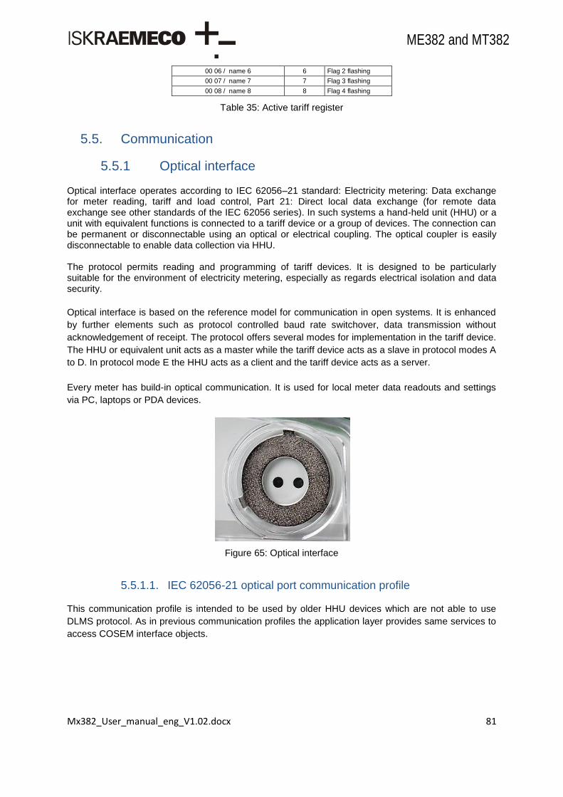
Mx382_User_manual_eng_V1.02.docx 81
ME382 and MT382
00 06 / name 6 6 Flag 2 flashing
00 07 / name 7 7 Flag 3 flashing
00 08 / name 8 8 Flag 4 flashing
Table 35: Active tariff register
5.5. Communication
5.5.1 Optical interface
Optical interface operates according to IEC 62056–21 standard: Electricity metering: Data exchange for meter reading, tariff and load control, Part 21: Direct local data exchange (for remote data exchange see other standards of the IEC 62056 series). In such systems a hand-held unit (HHU) or a unit with equivalent functions is connected to a tariff device or a group of devices. The connection can be permanent or disconnectable using an optical or electrical coupling. The optical coupler is easily disconnectable to enable data collection via HHU. The protocol permits reading and programming of tariff devices. It is designed to be particularly suitable for the environment of electricity metering, especially as regards electrical isolation and data security.
Optical interface is based on the reference model for communication in open systems. It is enhanced
by further elements such as protocol controlled baud rate switchover, data transmission without
acknowledgement of receipt. The protocol offers several modes for implementation in the tariff device.
The HHU or equivalent unit acts as a master while the tariff device acts as a slave in protocol modes A
to D. In protocol mode E the HHU acts as a client and the tariff device acts as a server.
Every meter has build-in optical communication. It is used for local meter data readouts and settings
via PC, laptops or PDA devices.
Figure 65: Optical interface
5.5.1.1. IEC 62056-21 optical port communication profile
This communication profile is intended to be used by older HHU devices which are not able to use
DLMS protocol. As in previous communication profiles the application layer provides same services to
access COSEM interface objects.

Mx382_User_manual_eng_V1.02.docx 82
ME382 and MT382
Figure 66: IEC optical port communication profile
5.5.1.2. COSEM/DLMS over IEC 62056-21 optical port
This communication profile is added to meter to ensure using of the same protocol on different
communication media.
The implementation provides mode “E” according to the IEC 62056-21 standard (formerly IEC 1107).
During the opening sequence the meter (server) is able to advise the HHU (client), that the advanced
mode “E” is available. If the HHU acknowledges it, they will continue the data exchange using HDLC-
based protocol. If the information exchange takes place then COSEM object model is used. If not data
exchange continues in the conventional mode “C”.
Figure 67: COSEM/DLMS optical port communication profile
5.5.1.3. IEC optical port setup
Communication Mode Defines the protocol used by the meter on the port. It can be selected between these three modes:
(0) - Protocol according to IEC 62056-21 (IEC 1107),
COSEM Interface Objects
IEC 62056-61, 62056-62
COSEM APPLICATION LAYER
IEC 62056-53
LLC LAYER
IEC 62056-46
PHYSICAL LAYER
IEC 62056-21
HDLC LAYER
IEC 62056-46
Application
Process
Application
Layer
LLC
Layer
MAC
Layer
PHY
Layer

Mx382_User_manual_eng_V1.02.docx 83
ME382 and MT382
(1) - Protocol according to IEC 62056-46 (DLMS UA),
(2) - Protocol not specified; proposed baud rate is used for setting the communication speed. Communication Speed Default baud rate defines baud rate for the opening sequence. Proposed baud rate defines baud rate to be proposed by the meter (relevant only for communication type 0 – (1107, modes A to E). Communication speed up to 115200 baud is possible (recommended is 38400 baud). Selection for Default and Proposed baud rate can be made between these rates:
(0) - 300 baud
(1) - 600 baud
(2) - 1200 baud
(3) - 2400 baud
(4) - 4800 baud
(5) - 9600 baud
(6) - 19200 baud
(7) - 38400 baud
(8) - 57600 baud
(9) - 115200 baud Response Time
Response time defines the minimum time between the reception of a request (end of request
telegram) and the transmission of the response (begin of response telegram). These two options are
available:
(0) – 20 ms,
(1) – 200 ms. Device Address Device address is intended to identify a meter in the group of meters. Each meter in one group must
therefore have a unique number. Eight digits (1 to 9) should be used.
Passwords
There is a password for communication channels:
settings password (used in IEC 1107 where entrance password needs to match this password and one of four authentication keys); eight digits (1 to 9) should be used,
5.5.1.4. IEC HDLC setup
Communication Speed Selection can be made between these rates:
(0) - 300 baud,
(1) - 600 baud,
(2) - 1200 baud,
(3) - 2400 baud,
(4) - 4800 baud,
(5) - 9600 baud,
(6) - 19200 baud,
(7) - 38400 baud,
(8) - 57600 baud,
(9) - 115200 baud.
Mx382_User_manual_eng_V1.02.docx 84
ME382 and MT382
Window Size Transmit
Attribute defines the maximum number of frames that a device or system can transmit before it needs
to receive an acknowledgement from a corresponding station. During logon, other values can be
negotiated.
Window Size Receive
Attribute defines the maximum number of frames that a device or system can receive before it needs
to transmit an acknowledgement to the corresponding station.
Maximum Info Length Transmit
Attribute defines the maximum information field length that a device can transmit.
Maximum Info Length Receive
Attribute defines the maximum information field length that a device can receive.
Inter Octet Time Out
Attribute defines the time, expressed in milliseconds, over which, when any character is received from
the primary station, the device will treat the already received data as a complete frame.
Inactivity Time Out
Attribute defines the time, expressed in seconds over which, when any frame is received from the
primary station, the device will process a disconnection. When set to 0, this means that the inactivity
time out is not operational.
Device Address
Attribute contains the physical device address of a device.
In the case of single byte addressing:
0x00 No Station Address,
0x01…0x0F Reserved for future use,
0x10...0x7D Usable address space,
0x7E „Calling‟ device address,
0x7F Broadcast address.
For effective use of functionalities, meter must be properly configured.
5.5.2 P1 interface
Port P1 is a read only interface. The meter has only one port P1. It is possible to connect more than
one device (OSM – Other Service Module) via splitter. Diagram for connecting one or more devices to
port P1 is shown in figure below.
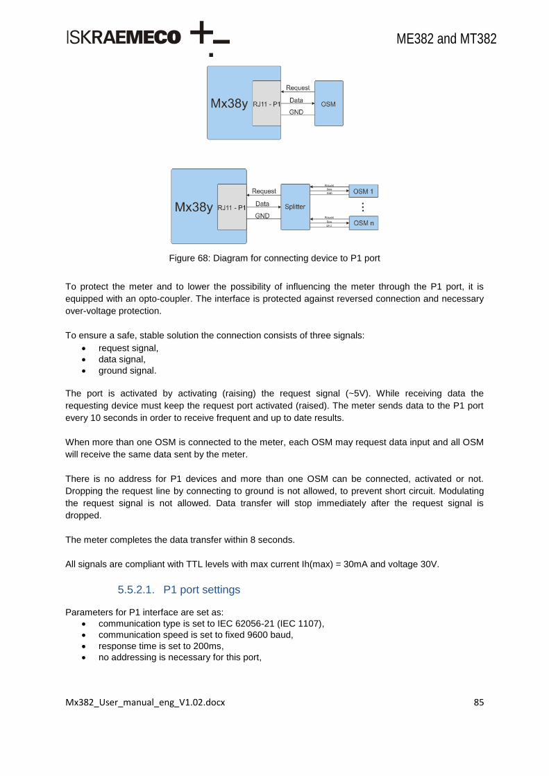
Mx382_User_manual_eng_V1.02.docx 85
ME382 and MT382
Figure 68: Diagram for connecting device to P1 port
To protect the meter and to lower the possibility of influencing the meter through the P1 port, it is
equipped with an opto-coupler. The interface is protected against reversed connection and necessary
over-voltage protection.
To ensure a safe, stable solution the connection consists of three signals:
request signal,
data signal,
ground signal.
The port is activated by activating (raising) the request signal (~5V). While receiving data the
requesting device must keep the request port activated (raised). The meter sends data to the P1 port
every 10 seconds in order to receive frequent and up to date results.
When more than one OSM is connected to the meter, each OSM may request data input and all OSM
will receive the same data sent by the meter.
There is no address for P1 devices and more than one OSM can be connected, activated or not.
Dropping the request line by connecting to ground is not allowed, to prevent short circuit. Modulating
the request signal is not allowed. Data transfer will stop immediately after the request signal is
dropped.
The meter completes the data transfer within 8 seconds.
All signals are compliant with TTL levels with max current Ih(max) = 30mA and voltage 30V.
5.5.2.1. P1 port settings
Parameters for P1 interface are set as:
communication type is set to IEC 62056-21 (IEC 1107),
communication speed is set to fixed 9600 baud,
response time is set to 200ms,
no addressing is necessary for this port,

Mx382_User_manual_eng_V1.02.docx 86
ME382 and MT382
no passwords are used for this port,
energy format is set to 8.2 (8 digits including 2 decimals) and with units Example: 1-0:1.8.0(000000.00*kWh),
demand format is set to 6.3 (6 digits including 3 decimals) and with units Example: 1-0:1.4.0(000.000*kW).
5.5.2.2. P1 physical connector
The connector is RJ11. The metering system holds a female connector. The customer can plug in a
standard RJ11 plug. Note that the connector in the metering system is physically accessible at all
times and is not sealed or protected by a sealed cover.
Pin # Signal name Description
1
2 Request Input
3 GND Ground
4
5 Data Output
6
Table 36: RJ11 pins
Figure 69: P1 port connection
5.5.2.3. P1 port readout list
With this object data readout information can be set. This information can usually be retrieved locally
over optical interface using IEC62056-21 mode C or remotely over P3 communication interface.
For effective use of functionalities, meter must be properly configured.
5.5.2.4. Consumer messages
If a device is connected, the meter will send the consumer message (code and/or text) over the P1
interface every 10 seconds.
The meter has storage capacity for one 64 character code message and one 1024 character text
message. Both messages are handled independently, but in the same way.
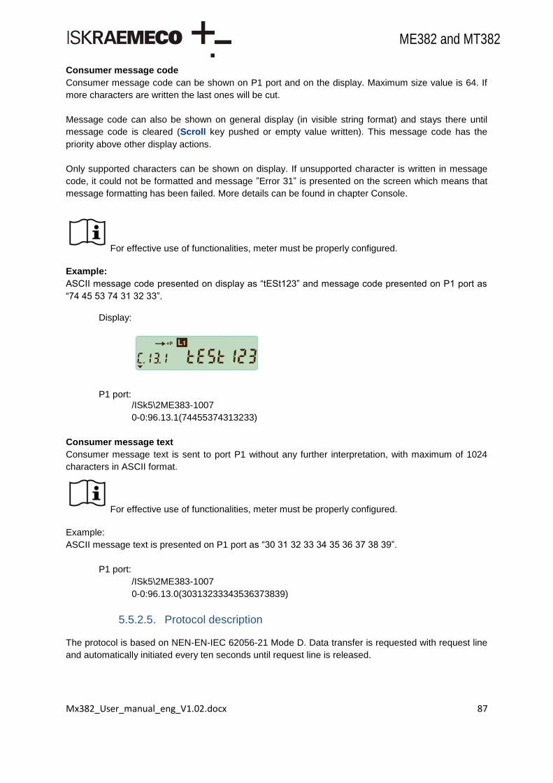
Mx382_User_manual_eng_V1.02.docx 87
ME382 and MT382
Consumer message code
Consumer message code can be shown on P1 port and on the display. Maximum size value is 64. If
more characters are written the last ones will be cut.
Message code can also be shown on general display (in visible string format) and stays there until
message code is cleared (Scroll key pushed or empty value written). This message code has the
priority above other display actions.
Only supported characters can be shown on display. If unsupported character is written in message
code, it could not be formatted and message ”Error 31” is presented on the screen which means that
message formatting has been failed. More details can be found in chapter Console.
For effective use of functionalities, meter must be properly configured.
Example:
ASCII message code presented on display as “tESt123” and message code presented on P1 port as
“74 45 53 74 31 32 33”.
Display:
P1 port: /ISk5\2ME383-1007
0-0:96.13.1(74455374313233)
Consumer message text
Consumer message text is sent to port P1 without any further interpretation, with maximum of 1024
characters in ASCII format.
For effective use of functionalities, meter must be properly configured.
Example:
ASCII message text is presented on P1 port as “30 31 32 33 34 35 36 37 38 39”.
P1 port:
/ISk5\2ME383-1007
0-0:96.13.0(30313233343536373839)
5.5.2.5. Protocol description
The protocol is based on NEN-EN-IEC 62056-21 Mode D. Data transfer is requested with request line
and automatically initiated every ten seconds until request line is released.
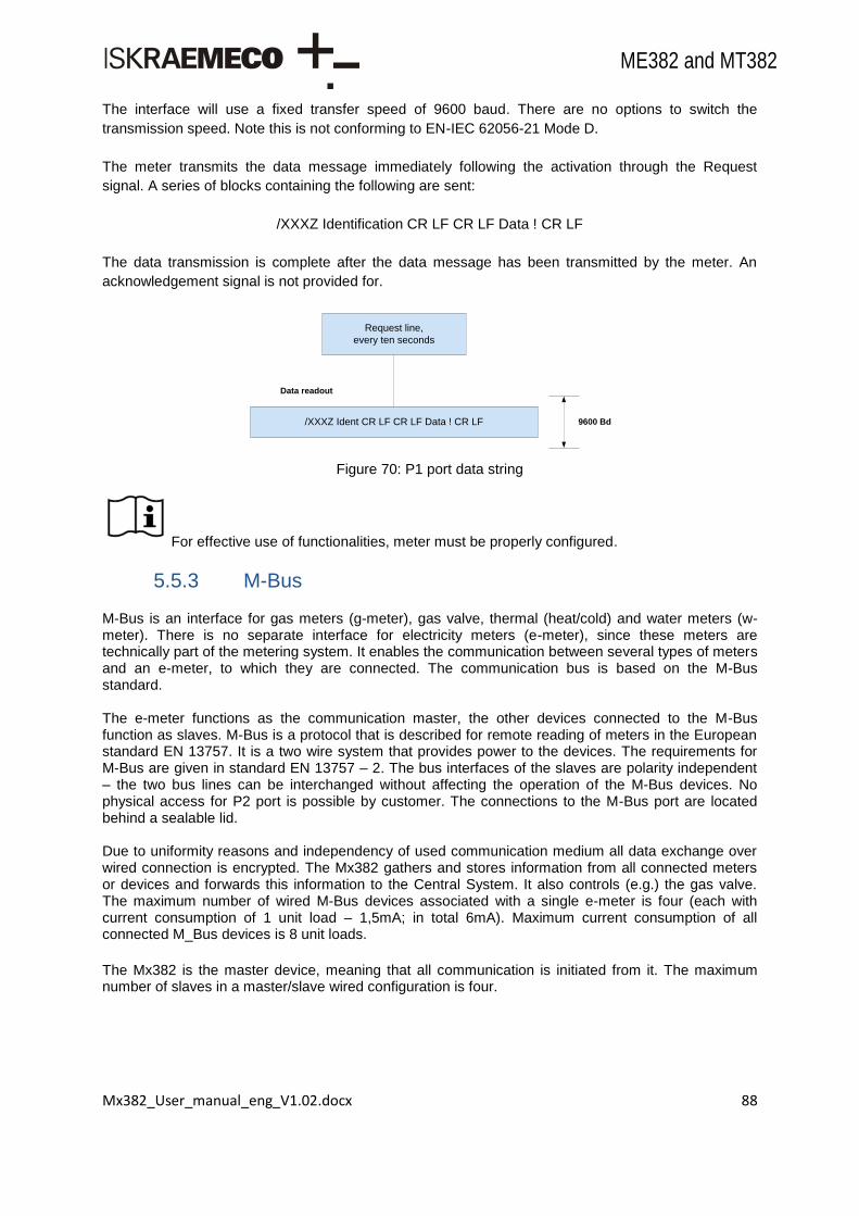
Mx382_User_manual_eng_V1.02.docx 88
ME382 and MT382
The interface will use a fixed transfer speed of 9600 baud. There are no options to switch the
transmission speed. Note this is not conforming to EN-IEC 62056-21 Mode D.
The meter transmits the data message immediately following the activation through the Request
signal. A series of blocks containing the following are sent:
/XXXZ Identification CR LF CR LF Data ! CR LF
The data transmission is complete after the data message has been transmitted by the meter. An
acknowledgement signal is not provided for.
Figure 70: P1 port data string
For effective use of functionalities, meter must be properly configured.
5.5.3 M-Bus
M-Bus is an interface for gas meters (g-meter), gas valve, thermal (heat/cold) and water meters (w-meter). There is no separate interface for electricity meters (e-meter), since these meters are technically part of the metering system. It enables the communication between several types of meters and an e-meter, to which they are connected. The communication bus is based on the M-Bus standard. The e-meter functions as the communication master, the other devices connected to the M-Bus function as slaves. M-Bus is a protocol that is described for remote reading of meters in the European standard EN 13757. It is a two wire system that provides power to the devices. The requirements for M-Bus are given in standard EN 13757 – 2. The bus interfaces of the slaves are polarity independent – the two bus lines can be interchanged without affecting the operation of the M-Bus devices. No physical access for P2 port is possible by customer. The connections to the M-Bus port are located behind a sealable lid. Due to uniformity reasons and independency of used communication medium all data exchange over wired connection is encrypted. The Mx382 gathers and stores information from all connected meters or devices and forwards this information to the Central System. It also controls (e.g.) the gas valve. The maximum number of wired M-Bus devices associated with a single e-meter is four (each with current consumption of 1 unit load – 1,5mA; in total 6mA). Maximum current consumption of all connected M_Bus devices is 8 unit loads.
The Mx382 is the master device, meaning that all communication is initiated from it. The maximum number of slaves in a master/slave wired configuration is four.
/XXXZ Ident CR LF CR LF Data ! CR LF
Request line,
every ten seconds
Data readout
9600 Bd

Mx382_User_manual_eng_V1.02.docx 89
ME382 and MT382
Figure 71: M-Bus master-slave configuration and dongle interface
As alternative solution for data exchange there is a combination of hardware or software paired meter-dongle interface. The dongle-master interface is confirming to the wired M-Bus specifications. Wireless meter data are exchanged according to EN 13757–4 standard. Devices are connected through the wireless (RF) M-Bus connection according to the T1/T2 mode of this standard. There is M-Bus communication interface integrated in all Mx382 meters according to EN 13757-2 and
EN 13757-3 which enables connection of four slave devices (water, gas or/and heat meters) and
maximum length of wiring 50 m.
Communication specification:
The communication speed is 2400 baud.
The e-meter act as an M-Bus master and the external device as an M-Bus slave. A maximum of four external slave devices is possible.
The standard used for the application layer: EN 13757-3
The standard used for the physical and link layer: EN 13757-2 During standard operation the e-meter will collect the consumption data by sequent polling the M-Bus
by the available device addresses. A maximum four of the external M-Bus meters could be read. The
retrieved data are organized in four measuring channels. One channel per each connected meter.
Figure 72: M-Bus channel model

Mx382_User_manual_eng_V1.02.docx 90
ME382 and MT382
Up to 4 values related to consumption data can be extracted from the M-Bus data frame and stored to
the e-meter registers. Rule how to map data from the M-Bus data frame to the e-meter register could
be defined by setting 4 DIF/VIF register for particular channel.
For effective use of functionalities, meter must be properly configured.
Read consumption values are represented forward to the system as COSEM extended register. Billing reads, data, could be retrieved daily, weekly, monthly at specified time or on request from the system.
5.5.3.1. M-Bus general installation procedures
During installation the M-Bus addresses of M-Bus devices will be registered in the e-meter. Note that
there are two possibilities: that M-Bus device address is set to zero before installation or M-Bus device
has already an address preset to the value different from 0.
M-Bus installation process is performed with three different actions:
with Slave_install method of the M-Bus Client Setup object (locally or remotely over communication interface),
with pressing the Reset key on the front plate of the e-meter,
with power up of the e-meter.
When an installation procedure is started the e-meter scans for physically connected M-Bus devices
for addresses from 1 to 6, and then also for address 0. After M-Bus device is registered in the e-meter
regular communications can begin.
5.5.3.2. Installation process
The uniqueness of M-Bus device identification is guaranteed with following parameters: M-Bus equipment identifier (Fabrication number), Manufacturer id, Version and Medium. Not all M-Bus devices include M-Bus equipment identifier in their M-Bus frame which causes the problem to identify the device completely. Beside that most of M-Bus devices include Serial number in their data header, but some also do not. Therefore scenario for installing the M-Bus device and logging the installation event in M-Bus standard event log is as follows:
1. If Serial number is available in M-Bus data header frame then event “New M-Bus device installed ch x [1]” is logged after first successful reading of device regardless on M-Bus equipment identifier (no encryption key needed at the moment).
2. If Serial number is not available but the M-Bus equipment identifier is then event “New M-Bus device installed ch x [1]” is set after first successful decryption of the frame (valid encryption key needed or no key needed if the data are not encrypted).
3. If none of those identifications are available (Serial number and M-Bus equipment identifier), then device is not installed properly (event for installation is not set [1]).
5.5.3.3. Scan for M-Bus devices
The e-meter manages a list of device addresses connected to. The list can hold four M-Bus devices.
During installation, the e-meter will scan for devices on the wired M-Bus. All responding devices will be
registered in the list.

Mx382_User_manual_eng_V1.02.docx 91
ME382 and MT382
If, for some reason, communication is required between e-meter and an M-Bus device registered in
the list, a request for the reading will be pushed to the queue and executed after scanning stops.
Two methods are supported to discover M-Bus devices connected to e-meter:
Poll for device with address 0,
Poll for devices with unregistered address.
5.5.3.4. Poll for Devices with Address 0
Address 0 is reserved for unconfigured M-Bus devices. Each unconfigured M-Bus device shall accept and answer all communication to this address (EN 13757-2 section 5.7.5).
The e-meter will select an unused device address and set M-Bus device address to it. Following this
procedure the e-meter will request M-Bus data, set event “New M-Bus device installed ch x [1]” and
raise alarm “M-Bus device installed ch x”.
5.5.3.5. Poll for Devices with Unregistered Address
Poll method is based on the procedure outlined in EN 13757-3 section 11.5. Addresses from 1 to 6 are
scanned and if there is at least one channel still empty also address 0 is scanned, no matter if the
address of the M-Bus device connected is included in the list of managed M-Bus devices or not.
Secondary address searching is not used. Following this procedure the e-meter will poll for the device
specific data.
While scanning, if a device answers on an address, the e-meter checks if the used address is in the
list or not.
If the used address is already in the list and answering M-Bus device is already in the list of managed M-Bus no action will follow.
If the used address is already in the list and the answering M-Bus device is not same to device already stored in the list of managed M-Bus devices, old M-Bus device is replaced with answering M-Bus device, event “New M-Bus device installed ch x [1]” is set and alarm “M-Bus device installed ch x” is raised.
If the used address is available and the answering M-Bus device is not in the list, a device is added to the list of managed M-Bus devices, event “New M-Bus device installed ch x [1]” is set and alarm “M-Bus device installed ch x” is raised.
If the used address is available and the answering M-Bus device is already in the list, a device is set to new available address, event “New M-Bus device installed ch x [1]” is set and alarm “M-Bus device installed ch x” is raised.
5.5.3.6. Key Installation
An installation procedure for M-Bus devices can be triggered by pushing an Reset key located under a
e-meter‟s key cover (see figures below), „‟P2 SEArch‟‟ is displayed first.
When a key is pressed e-meter starts to poll for device with an unregistered addresses from 1 to 6.
After that it will start to poll for devices with address 0. After successful installation, at least one of the
M-Bus devices on e-meter‟s display a flag designated with MB will be set on.
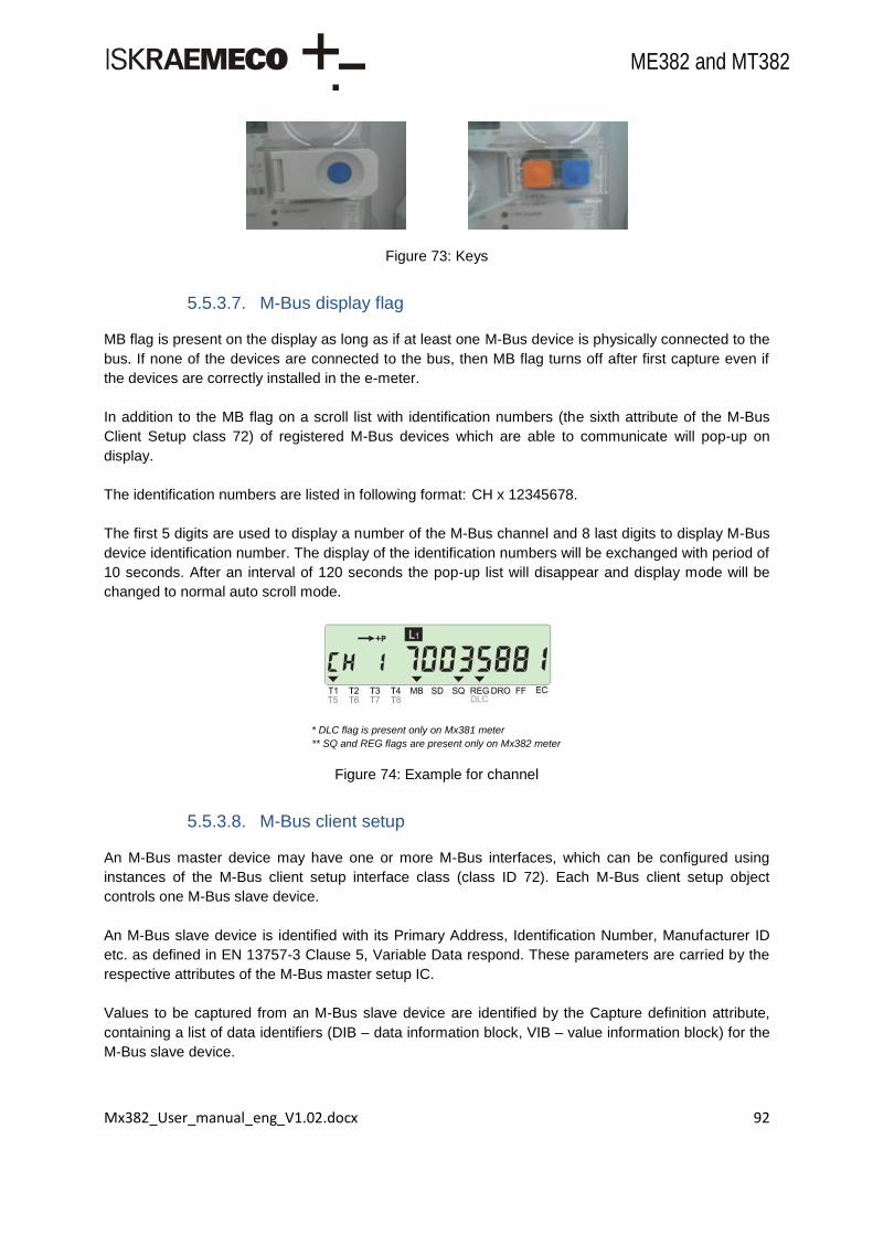
Mx382_User_manual_eng_V1.02.docx 92
ME382 and MT382
Figure 73: Keys
5.5.3.7. M-Bus display flag
MB flag is present on the display as long as if at least one M-Bus device is physically connected to the
bus. If none of the devices are connected to the bus, then MB flag turns off after first capture even if
the devices are correctly installed in the e-meter.
In addition to the MB flag on a scroll list with identification numbers (the sixth attribute of the M-Bus
Client Setup class 72) of registered M-Bus devices which are able to communicate will pop-up on
display.
The identification numbers are listed in following format: CH x 12345678.
The first 5 digits are used to display a number of the M-Bus channel and 8 last digits to display M-Bus
device identification number. The display of the identification numbers will be exchanged with period of
10 seconds. After an interval of 120 seconds the pop-up list will disappear and display mode will be
changed to normal auto scroll mode.
* DLC flag is present only on Mx381 meter
** SQ and REG flags are present only on Mx382 meter
Figure 74: Example for channel
5.5.3.8. M-Bus client setup
An M-Bus master device may have one or more M-Bus interfaces, which can be configured using
instances of the M-Bus client setup interface class (class ID 72). Each M-Bus client setup object
controls one M-Bus slave device.
An M-Bus slave device is identified with its Primary Address, Identification Number, Manufacturer ID
etc. as defined in EN 13757-3 Clause 5, Variable Data respond. These parameters are carried by the
respective attributes of the M-Bus master setup IC.
Values to be captured from an M-Bus slave device are identified by the Capture definition attribute,
containing a list of data identifiers (DIB – data information block, VIB – value information block) for the
M-Bus slave device.

Mx382_User_manual_eng_V1.02.docx 93
ME382 and MT382
Values from a slave device can be captured into M-Bus master value objects and M-Bus master profile
generic objects, periodically or on an appropriate trigger. It is also possible to perform operations like
installing and de-installing devices, setting the clock, setting the encryption key to M-Bus master and
slave.
Object includes setup parameters for M-Bus master for every M-Bus client. There is an object for each
of four channels (b=1-4).
5.5.3.9. M-Bus identification numbers
Device ID1
Device ID1 is M-Bus Equipment identifier. There is one object for each of four channels (b=1-4).
M-Bus equipment identifier is one of the parameters which define uniqueness of the device. For
successful reading of this identifier M-Bus device data must be unencrypted or successfully decrypted
(the proper encryption key must be previously uploaded to e-meter and M-Bus device). After that
binding process is completed.
Device ID2
Device ID2 is M-Bus Configurator data identifier. There is one object for each of four channels (b=1-4).
5.5.3.10. M-Bus result
M-Bus Master Value (result) holds last captured M-Bus value. There are four result objects for each of
four channels (b=1-4; e=1-4).
5.5.3.11. M-Bus load profile
M-Bus Master Load profile has hourly interval readings of M-Bus devices. The buffer must be filled
monotonously, i.e. no irregular entries are allowed. The profile is compressed type. Captured objects
include clock, status and M-Bus value objects (maximum 4). There is one object for each of four
channels (b=1-4).
Capture Objects Up to 6 objects can be set as capture objects.
Capture Period
Capture period defines the time distance between two captured data (seconds). The period is
synchronized with the hour (or minute); it always begins at completed hour (or minute). Value 0 of
“capture period” means no registration. Following capture periods (in seconds) are recommended to
choose from:
No registration – (0),
5 minute recording period – (300),
15 minute recording period – (900),
30 minute recording period – (1800),
1 hour recording period – (3600),
1 day recording period – (86400).
Specific Methods
M-Bus master load profile has two methods implemented:

Mx382_User_manual_eng_V1.02.docx 94
ME382 and MT382
Reset (erases captured values),
Capture (performs capturing when executed) - not supported for M-Bus load profile.
For effective use of functionalities, meter must be properly configured.
5.5.3.12. M-Bus status
M-Bus status object shows the sum of status register bits set. Each bit has a different meaning as
shown below. There is one status object for each of four channels.
5.5.3.13. M-Bus event log
M-Bus Event Log contains errors and alarms related to M-Bus devices (e.g. changes of the clock,
communication errors, fraud attempt, etc). The buffer must be filled monotonously, i.e. no irregular
entries are allowed. M-Bus Event Log structure consists of Timestamp and Event Code.
5.5.3.14. M-Bus event log status codes
M-Bus event code object holds the code from the last event triggered. These codes along with timestamps are then used in M-Bus event log.
5.5.3.15. M-Bus disconnector control
M-Bus master disconnect control
The object (0-b:24.4.0) controls the opening and closing of an M-Bus disconnector (e.g. gas valve).
There is one object for each of four channels (b=1-4).
Disconnect control mode:
Figure 75: M-Bus disconnect state diagram

Mx382_User_manual_eng_V1.02.docx 95
ME382 and MT382
It defines the mode of operation of M-Bus Disconnect control. These are possible modes:
Mode Description
0 None The disconnect control processes the command to go in „connected‟ state
1
Disconnection: Remote (b, c)
Local (g)
Reconnection: Remote (d) Manual (e) – Press the key on M-Bus device
2
Disconnection: Remote (b, c)
Local (g)
Reconnection: Remote (a) Manual (e) – Press the key on M-Bus device
3
Disconnection: Remote (b, c)
Local (g)
Reconnection: Remote (d) Manual (e) – Press the key on M-Bus device
4
Disconnection: Remote (b, c)
Local (g)
Reconnection: Remote (a) Manual (e) – Press the key on M-Bus device
5
Disconnection: Remote (b, c)
Local (g)
Reconnection: Remote (d) Manual (e) – Press the key on M-Bus device Local (h)
6
Disconnection: Remote (b, c)
Local (g)
Reconnection: Remote (d) Manual (e) – Press the key on M-Bus device Local (h)
Table 37: M-Bus disconnector modes
Disconnect Output State:
Disconnect Output State shows the actual physical state of the disconnect unit.
(0) – False,
(1) – True. Disconnect Control State:
Disconnect Control State defines the internal state of the disconnect unit. In the state Disconnected
the meter disconnects the customer. In the state Connected the customer is connected to the network
(gas, water...). In the state Ready to reconnection customer can perform reconnection manually on the
meter. Possible Disconnect control states are:
(0) - Disconnected – Customer is disconnected,
(1) - Connected – Customer is connected,
(2) - Ready for reconnection – Customer is disconnected. Reconnection needs to be performed manually on the meter.
Method Description:
Remote disconnect forces the disconnector into „disconnected‟ state if remote disconnection is enabled (control mode > 0).
Remote reconnect forces the disconnect unit into the „ready for reconnection‟ state if a direct remote reconnection is disabled (control mode = 1, 3, 5, 6), and forces it into the „connected‟ state if a direct remote reconnection is enabled (control mode = 2, 4).
M-Bus disconnect control scheduler
M-Bus disconnect control scheduler (0-1:15.0.1) is dedicated time point for connection or
disconnection. There is one object for all four M-Bus channels used.

Mx382_User_manual_eng_V1.02.docx 96
ME382 and MT382
Executed Script: For executed script M-Bus Disconnect control script table (0-1:10.0.106) should be used. Selector
needs to be selected according to the M-Bus channel used and according to selected command
(connect/disconnect).
M-Bus disconnector script table
There are 8 scripts defined to control each of four channels with remote reconnect and remote
disconnect service.
M-Bus master control log
Changes of the states (opened, closed, ready for reconnection) related to the M-Bus disconnect
control are recorded. There is one object for each of four channels (b=1-4). Contains all events related
to an M-Bus disconnector, e.g. a gas valve (open valve, close valve). M-Bus master control log
structure consists of Timestamp and Event Code.
M-Bus control event codes
M-Bus control event code object holds the code from the last event triggered. These codes along with timestamps are then used in event log. There is one object for each of four channels (b=1-4).
M-Bus client configuration
Object (0-0:128.50.1) is intended for additional configuration for different kind of M-Bus functionality
behavour. There are a lot of different scenarios of M-Bus functionality possible for some actions, for
example transferring the encryption key to the M-Bus slave, handling the M-Bus value registers,
profiles and logs in the case of decommissioning of the M-Bus slave, handling the capture actions in
relation with M-Bus device id, etc.
5.5.3.16. M-Bus alarms
There are four different groups of alarms used for M-Bus events which are directly related to devices,
connected to the e-meter:
M-Bus communication error,
M-Bus fraud attempt,
M-Bus device installed,
M-Bus valve alarm.
Each group consists of four different alarms, one per channel (1 - 4).
Alarm Alarm set condition Alarm reset condition
M-Bus Communication error
After 3 unsuccessful readings of the M-Bus device (device is physically disconnected)
After first successful reading of the M-Bus
device after communication error (device is
physically connected again)
M-Bus fraud attempt
When the data is successfully
received from the M-Bus device and
bit 6 (Fraud attempt) in the Error
status code of the Fixed data header
is set
When the data is successfully received
from the M-Bus device and bit 6 (Fraud
attempt) in the Error status code of the
Fixed data header is cleared
M-Bus device installed
After successful installation of the M-
Bus device to the free channel
After successful de-installation of the M-
Bus device from the channel (when Slave
de-install method or M-Bus remove method
are invoked)
Mx382_User_manual_eng_V1.02.docx 97
ME382 and MT382
M-Bus valve alarm
When M-Bus device sets the bit 7 in
Status attribute of the M-Bus Client
Setup object
When M-Bus device cleares the bit 7 in
Status attribute of the M-Bus Client Setup
object
Table 38: M-Bus alarms
5.5.4 GSM/GPRS communication module
A GSM/GPRS module supports communication over a cellular network using a modem, which is controlled by the meter. The meter‟s port on which a GSM/GPRS module is located executes an additional stack of protocol layers in order to provide necessary support for the modem to be operational. These layers can be separated as:
multiplex layer,
GSM/GPRS layer.
The implemented GSM/GPRS communication module is a class B modem, meaning that in the presence of a circuited-switched service an ongoing GPRS service is placed on hold.
Multiplex layer
The multiplex layer is implemented according to 3GPP TS 27.010 specification and enables multiple virtual channels to be created on a physical serial link. This way a GPRS or a CSD data session can run alongside the execution of AT commands.
GSM/GPRS layer
The GSM/GPRS protocol layer provides the following services:
modem initialization,
GSM/GPRS network diagnostic,
CSD data transfer (GSM),
packet oriented data transfer (GPRS),
SMS functionality,
modem reset.
Communication with the modem is established using virtual channels provided by the multiplexer
layer.
Application layer has possibility to manage GSM/GPRS network connection with objects Auto connect
(0-0:2.1.0.255) and Auto answer (0-0:2.2.0.255). Meter registration is provided over GPRS or SMS
communication and works with interaction with Push functionality.
5.5.4.1. Modem initialization
During a modem initialization phase a series of preset AT commands is sent to the modem to ensure properly modem configuration. An invalid response or no response to any of these commands can result in a modem reset when a valid response to at least one initialization command is not received within a 60 second limit. Besides the preconfigured initialization commands, the additional COSEM object can be used to set custom modem initialization commands. These initialization commands are sent to the modem following normal modem initialization process which is executed after each modem reset. The commands are set using the Modem configuration COSEM object (0-0:2.0.0*255). Up to five custom commands can be defined at the time. After all of the preconfigured initialization commands are sent (but not necessarily properly acknowledged by the modem) the transmission of custom commands takes place. Similarly, these commands need not to be acknowledged by the modem for

Mx382_User_manual_eng_V1.02.docx 98
ME382 and MT382
the next phase (i.e. diagnostic process) to begin. In case of no response or an invalid response from the modem, the custom command is resent but for no more than 100 times. The described modem initialization service is repeated (before each diagnostic process cycle) until every initialization command is acknowledged properly or a modem reset is performed.
The attributes of Modem configuration object are presented here:
Communication speed
Communication speed is the speed between the device and the modem, not necessarily the
communication speed of the WAN:
300 baud – (0),
600 baud – (1),
1200 baud – (2),
2400 baud – (3),
4800 baud – (4),
9600 baud – (5),
19200 baud – (6),
38400 baud – (7),
57600 baud – (8),
115200 baud – (9).
The attribute is of no relevance to the meter, since the baud rate on port using GSM/GPRS modem is
fixed to 115200 bps.
Initialization string
The initialization string contains all the necessary initialization commands to be sent to the modem in
order to configure it properly. If the array contains of more than one initialization string element, the
requests are sent in a sequence. The next request is sent after the expected response matching the
previous request and waiting a delay after response time (in ms), to allow the modem to execute the
request.
Modem Profile
It defines the mapping from Hayes standard commands/responses to modem specific strings. The
attribute is not used by the meter.
5.5.4.2. GSM/GPRS network diagnostic
The modem initialization service is followed by the network diagnostic service. It produces a sequence of diagnostic commands which are sent to the modem every 10 seconds. One diagnostic sequence contains the following set of commands:
AT+CPIN? (request SIM status),
AT+CSQ (request signal quality),
AT+CREG? (request GSM registration status),
AT+CGREG? (request GPRS registration status),
AT+COPS? (request network operator name),
AT+CGACT? (request PDP context activation status),
AT+CPMS? (request preferred message storage selected).
Each request must result in a corresponding respond. When no response or an invalid response is received, the error is noted by the GSM/GPRS layer implemented in the meter. If erroneous condition exists for more than 60 seconds, a modem restart sequence is initiated. The erroneous condition is

Mx382_User_manual_eng_V1.02.docx 99
ME382 and MT382
fulfilled when a valid response to at least one diagnostic command is not received within a 60 seconds limit.
To provide information about modem operation and its registration to different networks several
diagnostics COSEM objects are implemented:
GSM signal quality object value presents network signal strength. The value is retrieved as an <rssi> element, as a response to the AT+CSQ command. The retrieved values (as defined in 3GPP TS 27.007) have the following meaning:
• 0 -113 dBm or less, • 1 -111 dBm, • 2...30 -109... -53 dBm, • 31 -51 dBm or greater, • 99 not known or not detectable.
The value attribute of the GSM signal quality object can also contain value 255. The value indicates
that no valid response to the last AT+CSQ command was received from the modem.
GSM status object contains bit organized information about modem operation. The detailed bit
description is presented in the table below:
Bit Bit description
0 Modem registered to GSM network (home or roaming)
1 Installation call done or not active
2 Modem registered in GPRS network (home or roaming)
3 Modem has active PDP context
4-7 Reserved for future use
8 SIM card not detected or giving error response
9 SIM card requires PIN or PUK code
10 Modem reset pending
11 Installation call failed
12-15 Reserved for future use
Table 39: GSM status
ID GSM ICCID (0-0:128.20.2.255) object contains SIM identification number which is a 20-digit long
number used for physical SIM card identification.
GSM program version (0-0:128.20.3.255) object contains a special string to identify firmware of the
integrated modem. Version should be 7.46 or above.
GSM IMEI object (0-0:128.20.4.255) contains the IMEI number of the integrated modem. IMEI is a
unique identification of every device that communicates in mobile networks.
GSM network name (0-0:128.20.5.255) object presents the name (in alphanumeric format) of the
currently registered mobile network. If modem is not yet registered to the mobile network the object‟s
value field is empty.
GSM WIPsoft program version (0-0:128.20.6.255) object contains a special string to identify WIPsoft
program version of integrated modem. Version should be 5.42 or above.
GSM signal strength indication limit 1 (0-0:128.20.11.255) and

Mx382_User_manual_eng_V1.02.docx 100
ME382 and MT382
GSM signal strength indication limit 2 (0-0:128.20.12.255) objects are used in conjunction with
console‟s triangular cursor segments. If any of the cursors available is defined as a Signal Quality
Indicator (SQ), the GSM signal strength indication limit 2 object represents the threshold after which
the network signal is considered sufficient (resulting in SQ cursor being displayed). If the received
network signal strength is bellow the value specified in GSM signal strength indication limit 1 object,
SQ cursor is not displayed at all. Lastly, if the received network signal strength is between the values
specified by both objects, the SQ cursor blinks.
At startup or after every modem reset the value attribute of ID GSM ICCID, GSM IMEI and GSM
network name diagnostic objects contains “Reading…“ if the specific information has not yet been
retrieved from the modem.
5.5.4.3. CSD data connection (GSM)
When modem receives call, it sends the unsolicited ASCII “+CRING: <type of call>” string to the
meter‟s application. To get more information about incoming call (voice or data) is enabled by the
initialization command (AT+CRC=1). In order to be able to recognize the caller, at modem initialization
meter activates calling number presentation (AT+CLIP=1). Upon receiving the “+CRING: <type of
call>” and the “‟CLIP” string, meter decides whether to accept or reject incoming call. In case of
accepted call meter sends a confirmation command (ATA) to the modem. The confirmation command
is only sent if no other call is currently in progress. The GSM/GPRS layer‟s process responsible for
managing GSM connections then enters “connect” state where it awaits for the unsolicited
“CONNECT” string. After the “CONNECT” string is received, the process enters online state. The
connection is considered to be established and the data transfer can begin. If the “CONNECT” string is
not received within the valid time (i.e. the connection timeout has elapsed) or one of the unsolicited
strings “NOCARRIER”, “BUSY” or “NODIALTONE” is received instead, the corresponding process re-
enters “idle” state, during which new incoming connections are possible.
Figure 76: State transitions during a successful call establishment procedure
5.5.4.4. Packet data connection (GPRS)
The meter supports communication through GPRS mobile networks. In order to be visible within a GPRS network, the meters must establish connection to GPRS network first. Using special connection management functionality, meter can either be always connected to the GPRS network or only on request. When meter starts the modem, it does not connect to GPRS network by default (this means that modem is also not attached to GPRS network). Only when GPRS connection request is triggered from connection management block, meter starts activating GPRS connection. The meter first requests the

Mx382_User_manual_eng_V1.02.docx 101
ME382 and MT382
modem to attach to GPRS network. When attach is confirmed, PDP context activation is requested by the meter using configured APN, username and password. Dedicated object called GPRS Modem Setup is used for configuration of APN. GPRS Setup object attributes are used in the following way:
APN String defines the access point name of the network. The size of the APN string is limited to
maximum 40 characters.
PIN code
Enter value 0 if PIN code is disabled on the SIM card.
If PIN code is not disabled on the SIM card, PIN code should be entered in this field. The size
of the PIN code string is limited to maximum 4 characters (numbers).
Username and password for GPRS PDP context activation can be configured in PPP Setup object.
PPP Setup object attributes are used in the following way:
PHY reference References another object by its logical_name. The object referenced contains information about the specific physical layer interface, supporting the PPP layer. GPRS Setup object is referenced by default.
LCP options This attribute contains the parameters for the Link Control Protocol options. From the whole set of available options, only Authentication protocol is used. Authentication protocol option must be configured for PAP protocol.
PPP authentication
Contains the parameters required by the PPP authentication procedure used. PPP
authentication must be configured with appropriate PAP username and password, which will
be accepted by the network when PDP activation request is sent. The size of the username
and password strings is limited to maximum 32 characters.
After modem confirms PDP activation to the meter, meter activates appropriate server sockets (COSEM wrapper) in order to be able to communicate with remote peers.
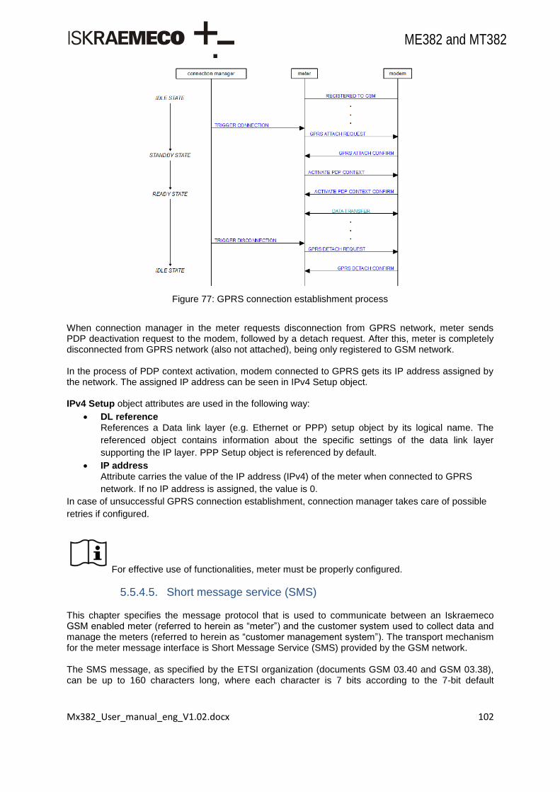
Mx382_User_manual_eng_V1.02.docx 102
ME382 and MT382
Figure 77: GPRS connection establishment process
When connection manager in the meter requests disconnection from GPRS network, meter sends PDP deactivation request to the modem, followed by a detach request. After this, meter is completely disconnected from GPRS network (also not attached), being only registered to GSM network. In the process of PDP context activation, modem connected to GPRS gets its IP address assigned by the network. The assigned IP address can be seen in IPv4 Setup object. IPv4 Setup object attributes are used in the following way:
DL reference References a Data link layer (e.g. Ethernet or PPP) setup object by its logical name. The
referenced object contains information about the specific settings of the data link layer
supporting the IP layer. PPP Setup object is referenced by default.
IP address Attribute carries the value of the IP address (IPv4) of the meter when connected to GPRS
network. If no IP address is assigned, the value is 0.
In case of unsuccessful GPRS connection establishment, connection manager takes care of possible
retries if configured.
For effective use of functionalities, meter must be properly configured.
5.5.4.5. Short message service (SMS)
This chapter specifies the message protocol that is used to communicate between an Iskraemeco GSM enabled meter (referred to herein as “meter”) and the customer system used to collect data and manage the meters (referred to herein as “customer management system”). The transport mechanism for the meter message interface is Short Message Service (SMS) provided by the GSM network. The SMS message, as specified by the ETSI organization (documents GSM 03.40 and GSM 03.38), can be up to 160 characters long, where each character is 7 bits according to the 7-bit default

Mx382_User_manual_eng_V1.02.docx 103
ME382 and MT382
alphabet. Eight-bit messages (max. 140 octets) are also available and are designed for data applications. The eight-bit PDU mode will be used to transfer SMS messages. SMS functionality has three features:
1. Incoming SMS data length is limited to one SMS to 140 octets and can be used to set some meter‟s objects or to trigger some actions.
2. Empty incoming SMS (data length 0) triggers GPRS wake-up procedure (establishing PDP context).
3. Outgoing SMS (triggered by the Push setup) is used to send a meter‟s objects to defined GMS subscriber (phone number).
The SMS channel supports xDLMS services with the following restrictions:
SMS is used as one-way channel only,
therefore only unconfirmed services are allowed (from client: SET, ACTION, unconfirmed, to client: Data-Notificaton),
therefore communication is restricted to/from the Pre-established client only. Security for SMS wake-up: Only SMS which are explicitly white listed in the attribute “list_of_allowed_callers” of the object “Auto Answer” are accepted by the meter. Receiving unconfirmed services from HES:
Only possible in pre-established association,
Depending on the security policy set global broadcast encryption and/or global authentication key may be used,
Services: unconfirmed SET and unconfirmed ACTION. SMS: The phone number is ASCII encoded, first digit left, only numbers, no blanks.
SMS initialization
For successful usage of SMS functionality two settings have to be performed:
Setting SMS centre address (SCA),
Add initialization string to Modem configuration, 0-0:2.0.0*255, attribute 3 (Initialization string).
Table 40: SMS centre address setting
Table above shows example of setting SMS centre address phone number to +3864100133 (145 = international format ). Setting auto answer object: Only SMS which are explicitly white listed in the attribute “list_of_allowed_callers” of the object “Auto Answer” are accepted by the meter. “Call type” should be set to “Wake-up request”
Table 41: Auto answer SMS list allowed callers
Modem configuration - Initialization string Value
1. Request +CSCA="+38641001333",145
2. Response OK
3. Delay after response 3000
Auto answer - List of callers Value
1. Caller ID *40123456
2. Call type 1 – Wake-up request

Mx382_User_manual_eng_V1.02.docx 104
ME382 and MT382
The table above shows example of phone number 040123456 (national format) or +38640123456 (international format) from which is allowed to receive SMS. To support both national and international phone number format, it is advised to use wildcard (*) instead of explicit phone number (*40123456 instead of 040123456 or +38640123456).
SMS APDU
The xDLMS PDUs are transported via the SMS channel by means of the “SMS Short Wrapper” defined below, where IDIS uses for the client the SAP (source and destination) 102 and for the server SAP (source and destination) 001. SMS Short Wrapper: The payload of an SMS message is the xDLMS APDU prepended with the identifier of the Destination_SAP and the Source_SAP as shown in figure below:
Figure 78: Destination_SAP and Source_SAP
Dst_SAP = Destination SAP Src_SAP = Source SAP Outgoing SMS (Meter HES): Destination SAP = 102 Source SAP = 001 Incoming SMS (HES Meter): Destination SAP = 001 Source SAP = 102

Mx382_User_manual_eng_V1.02.docx 105
ME382 and MT382
Figure 79: IDIS client and server model
Outgoing SMS
Sending SMS is triggered by the executing Push setup methods.
Push setup
1. Push setup – On wake-up
2. Push setup – Interval 1
3. Push setup – Interval 2
4. Push setup – Interval 3
5. Push setup – On alarm
6. Push setup – On power down
7. Push setup – Consumer Information (optional)
8. Push setup – On installation
Table 42: Push setup list
Push setup should be set to:
Push object list:
Any COSEM object in meter with read access,
Service type:
4 – SMS,
Destination type:
Phone number (ex: 0038641123456, +38641123456, 041123456),
Message type:
0 – COSEM APDU. Detailed description of Push setup attributes is in chapter Push Setup.

Mx382_User_manual_eng_V1.02.docx 106
ME382 and MT382
Service Centre Address (SCA) used for SMS sending (SMS-SUBMIT) should be set prior executing the method (see chapter SMS initialization). Data Coding Scheme (DCS) is always set to “8-bit data coding in the User Data”:
DCS Settings
Meter HES 0xF4
The VP (Validity Period) is the information field that gives an SME submitting an SMS-SUBMIT to the SMSC the possibility to include a specific time period value in the short message. The VP parameter value indicates the time period for which the short message is valid, i.e. for how long the SMSC shall guarantee its existence in the SMSC memory before delivery to the recipient expires.
VP Settings
Meter HES 0xA7 ( = 24 hours)
If XDLMS APDU data length is less than or equal to 138 octets (140 octets maximum SMS APDU – 2 octets for SMS Short Wrapper Header), meter sends Push data in single SMS. If data length is greater, meter sends two or more concatenated SMSes (according to specifications 3GPP TS 23.040). In this case, each part includes additional 6 octets User Data Header (8 bit reference number). Maximum data length (SMS Short Wrapper Header + Push data) is limited to 255 * (140 – 6) octets = 34.170 octets (see also chapter Concatenated SMS).
Incoming SMS
When incoming SMS is received, sender‟s phone number is compared with “List of callers” of the
object 0-0:2.2.0.255 (Auto answer) and if “Wake-up request” Call type is selected. If sender‟s phone
number is not on the list, or Call type is incorrect, SMS is discarded.
Coding of incoming SMS is always interpreted as 8-bit, regardless of Data Coding Scheme (DCS) of
the received SMS.
Length of incoming SMS is limited to 140 octets1 (single SMS). Length of xDLMS APDU data is 138
bytes (decreased by 2 octets used for SMS Short Header).
Incoming SMS Short Header is checked for correct association. Only pre-establish client association is
allowed:
Client (HES) – source – Association 102 (pre-establish client),
Server (Meter) – destination – Association 001 (management server).
If SMS Short Header is not correct, SMS is discarded.
SMS Short Header
0x01 Destination SAP – Server (Meter) – 001
0x66 Source SAP – Client (HES) – 102
xDLMS APDU
0xC1 COSEM DPU (CosemSetRequest)
1 Length of incoming SMS is limited to 140 octets with the macro GSM_SMS_IN_CONCAT_MAX_SEGMENTS.
Increasing SMS length requires more system resources (RAM, program code, netbuffers).

Mx382_User_manual_eng_V1.02.docx 107
ME382 and MT382
0x01 COSEM ADPU type (Normal)
0x00 Invoke ID and Priority
0x00 Class ID
0x01
0x00
Instance ID 0-0:96.13.0.255 (Consumer message text – Consumer information)
0x00
0x60
0x0D
0x00
0xFF
0x02 Attribute ID
0x00 AccessSelection
0x09
COSEM data: abcdef
0x06
0x61
0x62
0x63
0x64
0x65
0x66
Table 43: Example of SMS PDU
SMS wake-up request (empty incoming SMS)
When empty incoming SMS is received, sender‟s phone number is compared with “List of callers” of
the object 0-0:2.2.0.255 (Auto answer) and if “Wake-up request” Call type is selected. If sender‟s
phone number is not on the list, or Call type is incorrect, SMS is discarded.
The received message must be completely empty, otherwise it is not treated as a wake-up message.
When Auto connect (0-0:2.1.0.255) Mode is 103 or 104, GPRS connection (PDP context) is
established (GPRS Wake-up request).
Concatenated SMS
If data length, that has to be transferred by SMS, is greater than 140 octets, SMS is divided to multiple
SMS-es, according to SMS Point to Point specification, 3GPP TS 23.040: Technical realization of the
Short Message Service (SMS).
In every SMS segment, UDHI bit of PDU-type is set to 1: beginning of the User Data field contains additional 6 octet (8-bit reference number) Concatenated SMS header. Therefore every SMS segment holds 134 octets of user data. Maximum number of SMS segments is 255. Maximum data length for the concatenated SMS is limited to 255 * (140 – 6) octets = 34.170 octets. Table below shows the concatenated SMS (User data header + User data).
User Data Header (6 octets)
0x05 UDHL (User Data Header Length) 0x00 IEI (Identity Element Identifier): 0x00 = Concatenated message, 8 bit reference number 0x03 IEDL (Identity Element Data Length) 0xXX Reference number of this concatenated number. Each part must have the same reference number. 0xNN Total number of concatenated message parts (2 < 0xNN < 0xFF)

Mx382_User_manual_eng_V1.02.docx 108
ME382 and MT382
0xMM Number of this concatenated message part (1 < 0xMM < 0xNN)
User Data (max. 134 octets)
0xYY
User Data ...
0xZZ
Table 44: Concatenated SMS
For effective use of functionalities, meter must be properly configured.
5.5.4.6. Modem reset
Once the GSM/GPRS communication modem is running, network specific errors or broken
connections can cause the modem to become unresponsive to subsequent communication attempts.
The implemented modem reset mechanism enables the automatic restart and re-initialization of the
GSM/GPRS communication module, thus restoring it back to the fully operational mode.
Each time a modem reset is required, the meter attempts to perform a software reset (using
corresponding AT commands) first. If a software reset proves to be unsuccessful, a hardware reset is
performed by triggering modem HW reset signal. The occurrence of modem reset events is recorded
in the Communication event log (0-0:99.98.6.255) object under “Modem SW reset” (249) or “Modem
HW reset” (250) events.
The following scenarios can cause the modem reset to occur:
error in modem initialization,
error in modem diagnostic,
error during a CSD/GPRS connection,
no connection timeout has expired.
An error in initialization triggers a modem reset if the cause of the error is not resolved after 60
seconds from the time the error originated. This type of error occurs:
when the modem does not respond properly in time to the first AT command sent by the meter,
the modem‟s multiplexer mode could not be started,
modem replies to any subsequent (followed by the start of the multiplexer mode) AT commands were invalid or not received.
As described in chapter - Error! Reference source not found., modem diagnostics process
onstantly runs in the meter. In case of invalid or no response to diagnostic command for the period
longer than 60 seconds, meter triggers modem reset. Diagnostics process also triggers modem reset
in the following conditions last for more than 600 seconds:
modem does not return SIM ready,
modem reports signal quality 0 or 99,
modem is not able to register into GSM network.
The modem reset is triggered if a CSD/GPRS service cannot be established or if an error in the
termination of the service occurs due to some network specific error which results in GSM/GPRS
modem interface not being accessible to the connecting clients.

Mx382_User_manual_eng_V1.02.docx 109
ME382 and MT382
Each communication port has a separate timer which records the time duration since the last
successful communication over that particular port. A common timer for recording the time duration
since the last successful communication over any of the available ports is also implemented. When the
timer expires, the ports affected are re-initialized. If the port to be re-initialized is used as a
GSM/GPRS communication interface, additionally a modem reset is performed prior to any port re-
initialization.
The No connection timeout (0-0:128.20.30.255) object is used to configure timeout parameter for the
timers described above. The object is set to 30 hours by default. Each time a new value for the No
connection timeout object is set, the individual and common port timers are reset to 0. Setting the No
connection timeout object parameter to 0 disables the described monitoring functionality, hence no
resets due to lack of communication are performed.
The actual value used by the meter to monitor communication inactivity is calculated from the No
connection timeout parameter (NCT) and is therefore different. The actual value used is random value
between NCT and NCT+NCT/3. This is to prevent an excessive number of simultaneous GSM/GPRS
de-registrations performed by different meters when common source of error occurs in the network.
The table below further explains how errors in various stages of modem operation lead to possible
modem reset.
No. Stage Error result
1 Initialization service
1.1 first AT command sent no/invalid response
1.2 MUX startup MUX not started
1.3 Additional AT commands sent no/invalid response
2 Diagnostic service
2.1 Signal quality status insufficient quality, no/invalid response
2.2 SIM status SIM not inserted, no/invalid response
2.3 GSM registration registration failed, no/invalid response
2.4 GPRS registration registration failed, no/invalid response
2.5 Operator selection status no/invalid response
2.6 PDP context status PDP deactivated, no/invalid response
3 CSD/GPRS service
3.1 service establishment error during service establishment
3.2 service in progress unexpected service termination
3.3 service termination error during service termination
4 no connection timeout
4.1 no communication on port
Table 45: Modem reset triggers
Whenever a request to restart the modem is issued, the meter enters a special modem restart procedure. The following actions are executed:
IMSI detach is requested,
multiplexing mode on modem is closed,
modem software reset is requested,
in case of unsuccessful SW reset, modem HW reset is requested,
reset procedure finishes and reinitializes modem communication.
The above written order of the restart procedure actions is the same as the order of their execution.
The “IMSI DETACH REQUEST” and “IMSI DETACH RESPONSE” states are intended to detach the
modem from the mobile network by sending the AT+CFUN=4 command. After that, a close-down of
the multiplexer is attempted. When successful, a “SOFTWARE RESET REQUEST” follows. The

Mx382_User_manual_eng_V1.02.docx 110
ME382 and MT382
request (AT+CFUN=1,1) is only executed after an internal restart timeout (set to 180 seconds) added
with a random time between 0 and 60 seconds expires. The time is measured from the moment the
main GSM/GPRS process entries the restart procedure. When finished, GSM/GPRS process enters
the “RESTART FINISHED” state after which the communication port initialization is performed.
If any of the described states fails to execute properly / in time, the reset procedure enters
“HARDWARE RESET REQUEST” state. The HW reset procedure executes actual reset (triggering
dedicated HW reset signal) only after the internal restart timeout expires.
The entire modem reset procedure takes approximately 3 to 4 minutes to complete. Whether or not a
modem reset procedure is currently in progress can be observed using the GSM status object. If the
eleventh bit of the object‟s value attribute (Modem reset pending) is set to high, the modem reset
procedure is being executed.
5.5.4.7. TCP/IP based COSEM communication profile
This profile is implemented to be used in conjunction with a GPRS communication interface.
Figure 80: TCP/IP based COSEM communication profiles
COSEM wrapper
COSEM Wrapper protocol is a part of COSEM specification used for COSEM communication over IP
networks. The COSEM wrapper layer adds 8 bytes long header to the original COSEM message. The
wrapper header includes information about version, source wrapper port, destination wrapper port and
length. COSEM Wrapper header is followed by COSEM application data (APDU).
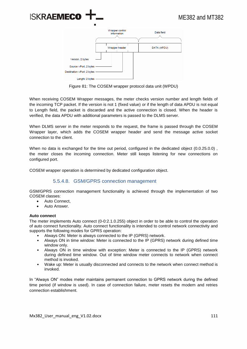
Mx382_User_manual_eng_V1.02.docx 111
ME382 and MT382
Figure 81: The COSEM wrapper protocol data unit (WPDU)
When receiving COSEM Wrapper messages, the meter checks version number and length fields of
the incoming TCP packet. If the version is not 1 (fixed value) or if the length of data APDU is not equal
to Length field, the packet is discarded and the active connection is closed. When the header is
verified, the data APDU with additional parameters is passed to the DLMS server.
When DLMS server in the meter responds to the request, the frame is passed through the COSEM
Wrapper layer, which adds the COSEM wrapper header and send the message active socket
connection to the client.
When no data is exchanged for the time out period, configured in the dedicated object (0.0.25.0.0) ,
the meter closes the incoming connection. Meter still keeps listening for new connections on
configured port.
COSEM wrapper operation is determined by dedicated configuration object.
5.5.4.8. GSM/GPRS connection management
GSM/GPRS connection management functionality is achieved through the implementation of two COSEM classes:
Auto Connect,
Auto Answer. Auto connect
The meter implements Auto connect (0-0:2.1.0.255) object in order to be able to control the operation of auto connect functionality. Auto connect functionality is intended to control network connectivity and supports the following modes for GPRS operation:
• Always ON: Meter is always connected to the IP (GPRS) network. • Always ON in time window: Meter is connected to the IP (GPRS) network during defined time
window only.
• Always ON in time window with exception: Meter is connected to the IP (GPRS) network during defined time window. Out of time window meter connects to network when connect method is invoked.
• Wake up: Meter is usually disconnected and connects to the network when connect method is invoked.
In “Always ON” modes meter maintains permanent connection to GPRS network during the defined
time period (if window is used). In case of connection failure, meter resets the modem and retries
connection establishment.

Mx382_User_manual_eng_V1.02.docx 112
ME382 and MT382
Figure 82: Auto connect operation in “Always ON“ modes during defined time window
When a connect method is invoked, the auto connect attempts to connect to the network if not already connected. When successful, the meter remains connected to the network until specific auto connect parameters change or network error occurs. If a connection attempt is unsuccessful, the auto connect re-attempts to connect to the network. The number of re-attempts is limited by the repetitions attribute. A connect method can only be invoked if the mode attribute is set to 103 (while outside of the defined calling window) or to 104.
Figure 83: Auto connect operation in modes 103 and 104 when a connection method is invoked
For effective use of functionalities, meter must be properly configured. Auto answer
The meter provides an Auto answer object intended to manage the following functionality of the exchangeable GSM/GPRS module:
answering to incoming calls,
handling GPRS wake-up requests.
Answering to incoming calls
The client system may initiate communication to the meter via circuit-switched-data (CSD) connection using GSM network. In order to support this Auto Answer object in the meter must be configured appropriately. Functionality of answering incoming calls is based on caller recognition, which is achieved by using GSM network CLIP service. In order to be able to accept incoming call, the meter must have auto answer object configured in one of the following way:
List of allowed callers is empty so meter answers incoming calls regardless of calling number.
Calling number reported with CLIP matches one of the calling numbers in list of allowed callers, which is associated with caller type for normal CSD call.
For effective use of functionalities, meter must be properly configured.

Mx382_User_manual_eng_V1.02.docx 113
ME382 and MT382
In addition to calling number checking, meter also answers incoming calls according to other
parameters (listening window, number of rings, etc.). For details see IDIS – Package 2 IP Profile.
Auto answer functionality answers only incoming data type of call. If incoming call is voice type of call
is only possible to make wake-up.
Because the implemented GSM/GPRS communication module is a class B modem (communication
over GPRS and CSD at the same time is not possible), any incoming CSD call is rejected if there is
any TCP session (over GPRS) active.
When CSD connection is established specific application checks activity on meter modem channel. If
there is no activity time more than Inactivity time out, 8th attribute of appropriate channel IEC HDLC
setup object (0-y:22.0.0*255), then meter makes hang-up and destroys connection.
Managing wake-up requests via CSD or SMS
In addition to “Always ON” modes, where GPRS connection is permanently activated during defined time period, the meter also supports GPRS connection establishment on request, so called wake-up. Wake-up is based on receiving CSD call notification (+CRING: <type of call>, +CLIP) or SMS. Upon receiving the wake-up call or SMS from the HES, the meter verifies the calling number according to configuration of the “auto answer” object. If the caller type of the calling number is set to (1) “wake-up request” in the list_of_allowed_callers the meter rejects incoming CSD call and immediately triggers GPRS connection request to the modem or in SMS case is depend of if incoming SMS is empty or not. The GPRS connection request is only triggered if appropriate mode (103 or 104) is configured in Auto Connect object. If mode 103 is configured in Auto Connect, also calling_window is checked. When Auto Answer mode is set to 0, meter does not check any other parameters of Auto Answer object, except list_of_allowed callers when managing wake-up request. When Auto Answer mode is set to 1 or 2, meter also takes listening_window, and number_of_calls into account when managing wake-up request.
For effective use of functionalities, meter must be properly configured. When Wake-up GPRS connection is established specific application checks activity on this
attachment. If there is no activity time more than Inactivity time out, 6th attribute of TCP-UDP setup
object (0-0:25.0.0*255), then meter destroys connection.
Meter registration
By meter registration meter sends its IP address and its system title over GPRS or SMS
communication to the HES using Data-Notification service. Mx382 meter triggers push method (Push
setup – On Installation (0-0:25.7.8*255)) by the GSM status object (0-0:128.20.1*255). The execution
of the push method results in transmission of the Data-Notification message to the set IP address or
phone number.
Push method is triggered by the GSM status object is depended of relation state of bits B1 and B11.
All relation states of bits and its meaning or action are shown in table below.
Mx382_User_manual_eng_V1.02.docx 114
ME382 and MT382
B1 B11 meaning
0 0 Trigger Push method (Installation On)
0 1 Invalid state
1 0 Installation call done or not active
1 1 Installation call failed
Table 46: GSM status object bits B1 and B11 relation states and meaning
5.5.5 Push setup
5.5.5.1. Description
Push method activates the push process leading to the elaboration and the sending of the push data
taking into account the values of the attributes defined in class 40.
For different push triggers seven mandatory configuration objects:
Push setup – On Wake-up (0-0:25.9.0.255),
Push setup – Interval_1 (0-1:25.9.0.255),
Push setup – Interval_2 (0-2:25.9.0.255),
Push setup – Interval_3 (0-3:25.9.0.255),
Push setup – On Alarm (0-4:25.9.0.255),
Push setup – On Power down (0-5:25.9.0.255),
Push setup – On Installation (0-7:25.9.0.255), and one optional configuration object:
Push setup – Consumer Information (0-6:25.9.0.255) are used.
Push setup currently support:
Object list: • All COSEM objects in meter with read access.
Service type: • 0 – TCP, • 4 – SMS.
Destination type: • IP address including the port number (ex: 10.253.49.30:10000) for service type TCP, • Phone number (ex: 0038641123456, +38641123456, 041123456) for service type
SMS.
Message type: • 0 – COSEM APDU.
Triggers: • Internal:
From Push script table:
If a monitor threshold is exceeded (alarm)
Schedulers: o Push action scheduler – Interval 1, o Push action scheduler – Interval 2, o Push action scheduler – Interval 3, o Push action scheduler – Consumer Information,
By an event (installation, power-down, established PDP context) • From HES:
Wake-up call (established PDP context), Executing method Push, Executing script from Push script table, Executing meter registration procedure.

Mx382_User_manual_eng_V1.02.docx 115
ME382 and MT382
Triggering Push method start a Push process on a selected Push object and can cause a message to
be sent to a dedicated destination. Push process is implemented inside Data_notification process,
which takes care of processing push objects, checking for established communication and preparing
the data to build proper COSEM_APDU.
Only one Push setup object is processed at once. Triggering multiple Push method at the same time is
resolved with looping one by one Push object classified according to the COSEM logical name until at
least one object is active.
For effective use of functionalities, meter must be properly configured.
Push process is running according to IDIS P2 specification.
5.5.5.2. Push setup on wake-up
After meter established PDP context object Push setup On Wake-Up is used to send to the HES its IP
address and system title using Data_notification service.
5.5.5.3. Push setup interval 1
Object Push setup Interval 1 is used to retrieve missing data from the last reading period(s), billing
data, quality of Supply data or Meter Supervision data using Data_notification service. For billing data
Data_notification message may contain total registers, rated registers, profiles and event logs. The
Quality of Supply data may be transferred using a dedicated Push setup object or it may be
transferred together with other data. Meter Supervision data is added next to the Billing data.
5.5.5.4. Push setup interval 2
Object Push setup Interval 2 is used to retrieve data from the last reading period(s), billing data, quality
of Supply data or Meter Supervision data using Data_notification service. For billing data
Data_notification message may contain total registers, rated registers, profiles and event logs. The
Quality of Supply data may be transferred using a dedicated Push setup object or it may be
transferred together with other data. Meter Supervision data is added next to the Billing data.
5.5.5.5. Push setup interval 3
Object Push setup Interval 3 is used to retrieve data from the last reading period(s), billing data, quality
of Supply data or Meter Supervision data using Data_notification service. For billing data
Data_notification message may contain total registers, rated registers, profiles and event logs. The
Quality of Supply data may be transferred using a dedicated Push setup object or it may be
transferred together with other data. Meter Supervision data is added next to the Billing data.

Mx382_User_manual_eng_V1.02.docx 116
ME382 and MT382
5.5.5.6. Push setup on alarm
Object Push setup On Alarm is used to send alarms and/or Quality of Supply data to the HES using
Data_notification service. The Quality of Supply data may be transferred using a dedicated Push setup
object or it may be transferred together with other data.
5.5.5.7. Push setup on power down
Object Push setup On power down is used to inform HES that meter is going to power-down and/or
sending Quality of Supply data. Using Data_notification service meter send its IP address and its
system title to the HES. The Quality of Supply data may be transferred using a dedicated Push setup
object or it may be transferred together with other data.
Figure 84: Power down scenario 1
Power good elapsed time is more than 20 minutes. At power-down Push setup On Power Down is
triggered. Currently active Push setup object is suspended but remain active to be processed after
power good. Power-up occurs before fixed delay (fd) and randomization time delay (rd) expires and
therefore data_notification is not send.
Figure 85: Power down scenario 2
For effective use of functionalities, meter must be properly configured. Power good elapsed time is more than 20 minutes. At power-down Push setup On Power Down is
triggered. Currently active Push setup object is suspended but remain active to be processed after
power good. If sum of fixed delay (fd) and randomization delay (rd) is less than 40 seconds then
data_notification can be send successfully. If power up occurred immediatly after fixed (fd) and
randomization time delay (rd) expires, data_notification could not be sent, because at power-up Push
setup On Power Down is suspended.
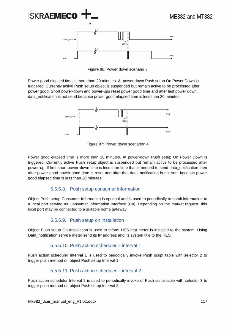
Mx382_User_manual_eng_V1.02.docx 117
ME382 and MT382
Figure 86: Power down scenario 3
Power good elapsed time is more than 20 minutes. At power down Push setup On Power Down is
triggered. Currently active Push setup object is suspended but remain active to be processed after
power good. Short power-down and power-ups reset power good time and after last power down,
data_notification is not send because power good elapsed time is less than 20 minutes.
Figure 87: Power down scenarion 4
Power good elapsed time is more than 20 minutes. At power-down Push setup On Power Down is
triggered. Currently active Push setup object is suspended but remain active to be processed after
power-up. If first short power-down time is less than time that is needed to send data_notification then
after power good power good time is reset and after that data_notification is not sent because power
good elapsed time is less than 20 minutes.
5.5.5.8. Push setup consumer information
Object Push setup Consumer Information is optional and is used to periodically transmit information to
a local port serving as Consumer Information Interface (CII). Depending on the market request, this
local port may be connected to a suitable home gateway.
5.5.5.9. Push setup on installation
Object Push setup On Installation is used to inform HES that meter is installed to the system. Using
Data_notification service meter send its IP address and its system title to the HES.
5.5.5.10. Push action scheduler – interval 1
Push action scheduler Interval 1 is used to periodically invoke Push script table with selector 2 to
trigger push method on object Push setup Interval 1.
5.5.5.11. Push action scheduler – interval 2
Push action scheduler Interval 2 is used to periodically invoke of Push script table with selector 3 to
trigger push method on object Push setup Interval 2.

Mx382_User_manual_eng_V1.02.docx 118
ME382 and MT382
5.5.5.12. Push action scheduler – interval 3
Push action scheduler Interval 3 is used to periodically invoke of Push script table with selector 4 to
trigger push method on object Push setup Interval 3.
5.5.5.13. Push action scheduler – consumer information
Push action scheduler Consumer Information is optional and is used to periodically invoke of Push
script table with selector 7 to trigger push method on object Push setup Consumer Information.
5.5.5.14. Push script table
Push script table contain scripts which are used to trigger push method on Push setup objects. To
each Push setup object belongs one script.
5.6. Fraud detection
5.6.1 Meter cover open and terminal cover open
These detectors (switches) trigger an event that lets the user know if and when terminal block cover or meter cover were opened.
Figure 88: Terminal cover opening switch
5.6.2 Magnetic field detection
This detector (reed relay) triggers a magnetic field detected event (fraud detection log event 42) and no more magnetic field detection event (fraud detection log event 43) that is recorded in fraud detection log-book if and when there was an external magnetic field (30-35mT) near the meter. This is used for security reasons as some public might try to influence the meters accuracy.
See list of fraud events in Table 50.
5.7. Meter programming
Programming of the meter as well as application part of FW upgrade can be done locally or remotely
in compliance with the predefined security levels. The objects in the meter are secured with four
authentication levels or most severe with param key. FW rewrite is applied in compliance with
standards (Welmec).
For effective use of functionalities, meter must be properly configured.

Mx382_User_manual_eng_V1.02.docx 119
ME382 and MT382
5.8. Configuration program change
This two objects record number of configuration (parameter) changes (0-0:96.2.0) in the meter along
with the timestamp of the last change (0-0:96.2.1):
Number of configuration program changes,
Date of last configuration program change.

Mx382_User_manual_eng_V1.02.docx 120
ME382 and MT382
6. Description of main meter functionalities
6.1. Measurements
Beside energy and power measurement and registration and instantaneous values measurement and
registration (power, voltage, current, power factor, frequency) the following meter functions are
available:
Power Quality Measurements according EN 50160,
Power Quality Measurements data available as instantaneous or average data,
Voltage sags and swells,
Undervoltages, overvoltages,
Detection of minimum, maximum - daily voltage,
Detection of instantaneous power factor; per phase, three-phase registers,
Detection of last average power factor,
Registration of three phase and phase power-downs and duration (long and short).
See also Chapter 3.6.
6.2. Sequences
These objects are used to configure data for quick readout, either from display or PC. Each register
can accept maximum of 32 visible entries. They are usually used for most needed meter information
such as energy and demand values or date and time. Only objects attribute 2 (Capture objects) is
needed for correct setup entry.
The meters have three different sequences:
P1 port readout sequence (d=0),
General display readout sequence (d=1),
Alternate display readout sequence (d=2).
For effective use of functionalities, meter must be properly configured.
6.2.1 P1 port readout list
With P1 port readout list object (0.0:21.0.0.255) data readout information can be set.
For effective use of functionalities, meter must be properly configured.
6.2.2 General display readout
With General display readout object (0.0:21.0.1.255) the information visible on meter‟s display in auto
scroll mode can be set. This information automatically scrolls on display every few seconds (default
period is 10 seconds) without any need to press any key.

Mx382_User_manual_eng_V1.02.docx 121
ME382 and MT382
Presentation of strings on display is performed with horizontal scroll, if the size of string is larger than
the size of alphanumeric field for value on display (8 characters). Horizontal scroll shift period is one
second. When the horizontal scroll is performed in Auto scroll mode, the auto scroll period (10s) is
extended until end of the string is reached.
The objects, that are not intended to show on the display, will not be displayed, if they are included in
General display readout list (0-0:21.0.1) or in Alternate display readout list (0-0:21.0.2). The message
code Error 11 (Ident format failed) will be displayed instead.
For effective use of functionalities, meter must be properly configured.
6.2.3 Alternate display readout
With Alternate display readout object (0.0:21.0.2.255) the information visible on meter‟s display in
manual-scroll mode can be set. Each press on Scroll key in manual-scroll mode scrolls to the next
item from the Alternate display readout list. In transition from auto-scroll mode to manual-scroll mode
the LCD test is performed (all segments on). After some time of inactivity in manual-scroll mode
(default escape time is 2 minutes) the meter returns into auto-scroll mode.
For effective use of functionalities, meter must be properly configured.
6.3. Load profile recorder
Two general purpose load profiles are available in Houdini meter. Each of two can capture any of the
basic type object value present in the meter. Basic object type means any object attribute that has
non-structured content.
The meter has two load profiles (LP with period 1 and LP with period 2) which are instances of the
COSEM class the “Profile generic”, which defines a generalized concept to store dynamic process
values of capture objects. A profile has a buffer to store captured data, therefore each profile has a
limit of stored data. More capture objects we select less total captured data will be possible to store.
After a call of “reset” method, the buffer does not contain any entries, and this value is zero. Two read
only attributes show status of this:
Profile Entries attribute specifies how many entries could be retained in the buffer,
Entries in Use attribute counts the number of entries stored in the buffer.
In each profile up to 32 objects can be registered. Number of objects directly defines the length of one
record. Minimum and maximum profile capacity depends on the capture period selected and number
of capture objects set and meter type used (ME382 or MT382).
For effective use of functionalities, meter must be properly configured.

Mx382_User_manual_eng_V1.02.docx 122
ME382 and MT382
Data in a load-profile recorder are accompanied with a timestamp and with the meter status in the last
saving period as well as with a check sum. The timestamp indicates the end of a registration period.
Both profiles are compressed type – only one (first) timestamp is shown.
Profiles are implemented as FIFO buffers. Each record has associated a unique record number.
Within one load profile more records can have same timestamp (in case time is shifted back) but all
have different record numbers. When reading load profiles records are being put out according to their
record number in increasing order.
Operation is IDIS P2 specification compliant.
6.3.1 Profile
6.3.1.1. Load profile with period 1 and 2
Capture Objects
Up to 32 objects can be captured (recorded) with capture period.
Capture Period
Capture period is variable which defines the time distance between two captured data‟s (seconds).
The capture period of the profile can be specified by “capture period” attribute. It can be set to 5, 10,
15, 30, 60 minutes or one day. The period is synchronized with the hour; it always begins at completed
hour. Value 0 of “capture period” means no registration. The profile buffer can be cleared by invocation
of the “Profile generic” method “reset”. These recording periods (in seconds) are recommended to
choose from:
0 – No registration,
300 – 5 minute recording period,
600 – 10 minute recording period,
900 – 15 minute recording period,
1800– 30 minute recording period,
3600 – 1 hour recording period,
86400 – 1 day recording period.
Methods
Load profile has two methods implemented:
Reset (erases captured values),
Capture (performs capturing when executed) - not supported for load profile.
Load profile with period 2 has same functionality as profile with period 1, only difference is in less
reserved space for records in the meter.
6.3.2 Profile status
There are two status registers:
Profile status for load profile with period 1,
Profile status for load profile with period 2. The AMR Profile status code has a size of 1 byte and is shown in decimal form. The following table
describes the state and the function of all bits.

Mx382_User_manual_eng_V1.02.docx 123
ME382 and MT382
If one of the events defined below has occurred during capture period, corresponding event code is
added to the profile status register. By adding event codes to the profile status register all events
occurred during capture period are stored to the profile buffer at the end of capture period. After
storing a value of profile status register together with meter stands in the profile buffer meter resets
profile status register to zero value. These status notifications shown in load profile readout are:
Status Bit Hex Dec Description
None 0x00 0 No event
Device
disturbance ERR 0 0x01 1
A serious error such as a hardware failure or a checksum
error has occurred.
Clock battery
discharged CIV 1 0x02 2
The power reserve of the clock has been exhausted. The
time is declared as invalid.
Measurement
value
disturbed
DNV 2 0x04 4
Indicates that the current entry may not be used for billing
e.g. due to time shift or if no values have been recorded
during the capture period.
Season
changed DST 3 0x08 8 Indicates that daylight savings is enabled
Reset
cumulation 4 0x10 16 Reserved: The reserved bit is always set to 0
Device clock
changed CAD 5 0x20 32
The bit is set when clock has been adjusted more than the
synchronization limit.
Power up PUP 6 0x40 64 Reserved: The reserved bit is always set to 0
Power down PDN 7 0x80 128 This bit is set to indicate that an all-phase power failure
occurred
Table 47: List of profile statuses
6.4. Billing profile recorder
Billing functionality in the meter is used to provide process and storage for managing billing data. Data
stored in the process of billing and time points when billing process is executed can be defined as
parameters according to implemented object model.
All billing data are stored in form of buffer within object of class profile generic. Two billing profile
objects are implemented in the meter. Each billing profile can have its own set of capture objects
defined. Those two profiles do not use their capture period so this attribute should be set to 0.
Capturing object values into buffer of the two billing profiles is triggered by execution of dedicated
script from “End of billing script table”. This script table contains two predefined scripts, one for
execution of “Billing profile 1” capture method and one for execution of “Billing profile 2” capture
method.
The following actions are carried out by the meter when script 1 of “End of billing script table” is
executed:
Execute capture method for “Billing profile 1”,
Reset maximum demand registers,
Reset minimum power factor (value is set to 1),
Increment “Total billing reset counter”,
Create event in log-book to log execution of billing reset.

Mx382_User_manual_eng_V1.02.docx 124
ME382 and MT382
The following actions are carried out by the meter when script 2 of “End of billing script table” is
executed:
Execute capture method for “Billing profile 2”.
Each of two scripts from “End of billing script table” can be executed in two ways:
By invoking execute method of “End of billing script table” via communication channel,
Internally by “Single Action Schedule” object which refers to specific script.
Two single action schedule objects are dedicated to billing process. Each of those two can refer to any
of the two scripts of “End of billing period” script table. Each single action schedule can have up to four
time definitions that trigger execution of its associated script. Time definitions can be set as periodic
(e.g. every day, every month …) or exact specified date-time.
The billing reset is executed immediately when triggered (via single action schedule or via
communication channel), there is no waiting for completion of measurement period. When
synchronization with measurement period is required, user should assure this by setting appropriate
times in single action schedules.
If clock is set forward or backward over n periodic billing execution times, then only one entry will be
generated in billing profile, marked with first time of periodic definition appearing after old time. The
event in log-book will be generated with the new set time.
If clock is set forward over n exactly specified billing execution date-times, then only one will be
generated in billing profile, marked with the nearest time appearing after old time.
If billing reset (end of billing period) is set to occur while the meter is powered-down (power-down
before billing reset), the billing reset will occur immediately when meter is powered-up again. The
event in log-book will be generated with the timestamp when meter is powered-up.
The data of the past billing periods stored in profile buffer cannot be displayed on LCD, they can be
read out via communication channels, i.e. via optical port or dedicated modem.
6.4.1 End of billing period
Script is executed once a month typically at midnight at the end/start of every month, however other
times can be set. Execution can be disabled if the execution time is left empty or set with “FFFFFFFF",
"FFFFFFFFFF”. Activation time should be rounded up to a minute (seconds set to 00 as defined in
COSEM Blue Book 10th Edition).
There are two Single action schedule objects, 0-0:15.0.0 (end of billing period 1 – d=0) and 0-0:15.1.0
(end of billing period 2- d=2), which trigger billing actions and represent start point for Billing Read E-
meter events.
6.4.2 End of billing period script table
Each of billing sources invokes script from “end of billing” script table. That script starts the billing
process. The main function of billing script table is to provide interface for execution of actions related
to each specific billing type when script is executed.

Mx382_User_manual_eng_V1.02.docx 125
ME382 and MT382
6.4.3 Billing period counter
Billing period counter counts all billings that were performed in the past.
6.4.4 Data of billing period – Billing profile
Billing profile is the storage for billing data, captured by execution of billing actions. Billing profile buffer
is organized as an array of entries. Each entry is a snapshot of capture object values at the moment of
capture time. By default the first data in billing profile entries is time mark (0-0:1.0.0). Capture time is
triggered from single action scheduler.
Each billing profile has the capacity of:
35 entries with default number of capture objects (5) (clock + 4 objects of size 4 bytes),
88 with minimum number of captured objects (2) (clock + 1 object of size 4 bytes),
5 entries with maximum number of capture objects (32) (clock + 31 objects of size 4 bytes).
There are two objects of billing profiles:
Data of billing period 1 (d=1),
Data of billing period 2 (d=2).
6.5. Event logs
Basic principle is shown in a diagram below:

Mx382_User_manual_eng_V1.02.docx 126
ME382 and MT382
Figure 89: Event handling
Events are generated by the meter itself or by its environment. All these events are logged in several
event logs. Every event has a unique code to identify the action which has triggered it. Every event is
assigned to one event log (event filter) and it is only stored there. The E-meter features ten different
event logs as described below. All logs except the power failure log have the same basic structure
(timestamp and event code). The structure per event log is fixed, i.e. it is not possible to store different
parameters per event.
Mx382 meters support different event codes. The Event system object (1-0:96.245.0.255) enables the
meter to provide three different types of event code presentation. Depending on projects these can be
set to:
VDEW / IE - (0),
IDIS - (1),
EDF - (2).

Mx382_User_manual_eng_V1.02.docx 127
ME382 and MT382
Change takes effect after power-down/up or reset.
For effective use of functionalities, meter must be properly configured.
6.5.1 Event code objects
Events are generated by the meter itself of by its environment. Each type of an event is presented with
a unique code (event code) to identify the action which has triggered it. Event codes are stored in
corresponding Event code objects. Each event object holds only the most recent event. The event
code object has the value of 0 until the first event is detected/generated by the meter or every time a
power-up is performed.
6.5.2 Event log objects
Instances of event code objects are captured in corresponding event logs. Event log objects are
instances of COSEM class “profile generic” and are used to store events. They are organized as FIFO
buffers where records are sorted by time. Once the buffer is full, the oldest entry in the buffer is the
first to be replaced. The capacity (maximum number of records in a buffer) of the event log objects
varies from object to object. Records in the buffer are captured asynchronously, as the events occur.
The majority of the supported event log objects (with the exception of Power failure event log) follow
the same basic structure containing the timestamp (time of the occurrence of the event) and the event
code object.
The meter features the following event log objects:
Event log object logical name capacity captured objects
Standard event log 0-0:99.98.0.255 100 0-0:1.0.0.255
0-0:96.11.0.255
Fraud detection log 0-0:99.98.1.255 30 0-0:1.0.0.255
0-0:96.11.1.255
Disconnector control log 0-0:99.98.2.255 30 0-0:1.0.0.255
0-0:96.11.2.255
M-Bus event log 0-0:99.98.3.255 30 0-0:1.0.0.255
0-0:96.11.3.255
Power quality event log 0-0:99.98.4.255 100 0-0:1.0.0.255
0-0:96.11.4.255
M-Bus control log 2 0-x:24.5.0.255 12
0-0:1.0.0.255
0-x:96.11.4.255
Power failure event log 1-0:99.97.0.255 10 0-0:1.0.0.255
0-0:96.7.19.255
Certification data log 1-0:99.99.0.255 100
0-0:1.0.0.255
0-0:96.128.0.255
0-0:96.128.1.255
0-0:96.128.2.255
Communication event log 0-0:99.98.6.255 255 0-0:1.0.0.255
0-0:96.11.6.255
Table 48: Event log objects
2 x represent M-Bus channel from 1 to 4

Mx382_User_manual_eng_V1.02.docx 128
ME382 and MT382
6.5.3 Standard event log
Standard event log contains all events not recorded in a special event log, e.g. changes of the clock,
changes of the configuration, clearing of profiles, all kind of self check errors, activation of new
parameters, activation of new time of use, etc. Standard event log structure consists of timestamp and
event code.
6.5.3.1. Standard event log codes
Standard event log code object holds the code from the last event triggered. These codes along with
timestamps are then used in event log.
Standard IDIS event codes are listed in Table below.
IDIS
event
code
Event name Event description
1 Power Down Indicates a complete power down of the device. Please note that this is related to the device and not
necessarily to the network.
2 Power Up Indicates that the device is powered again after a complete power down.
3 DST enabled or
disabled
Indicates the regular change from and to daylight saving time. The timestamp shows the time after
the change. This event is not set in case of manual clock changes and in case of power failures.
4 Clock adjusted
(old date/time)
Indicates that the clock has been adjusted. The date/time that is stored in the event log is the old
date/time before adjusting the clock.
5 Clock adjusted
(new date/time)
Indicates that the clock has been adjusted. The date/time that is stored in the event log is the new
date/time after adjusting the clock.
6 Clock invalid Indicates that clock may be invalid, i.e. if the power reserve of the clock has exhausted. It is set at
power up.
7 Replace Battery Indicates that the battery must be exchanged due to the expected end of life time.
8 Battery voltage low Indicates that the current battery voltage is low.
9 TOU activated Indicates that the passive TOU has been activated.
10 Error register
cleared Indicates that the error register was cleared.
11 Alarm register
cleared Indicates that the alarm register was cleared.
12 Program memory
error Indicates a physical or a logical error in the program memory.
13 RAM error Indicates a physical or a logical error in the RAM
14 NV memory error Indicates a physical or a logical error in the non volatile memory
15 Watchdog error Indicates a watch dog reset or a hardware reset of the microcontroller.
16 Measurement
system error Indicates a logical or physical error in the measurement system
17 Firmware ready for
activation
Indicates that the new firmware has been successfully downloaded and verified, i.e. it is ready for
activation
18 Firmware activated Indicates that a new firmware has been activated
19 Passive TOU
programmed The passive structures of TOU or a new activation date/time were programmed
20 External alert
detected Indicates signal detected on the meter's input terminal (2)
21 PDP context
established Indicates that the meter has established a new PDP (packet data protocol) context (2)
47
One or more
parameters
changed
48 Global key(s)
changed One or more global keys changed

Mx382_User_manual_eng_V1.02.docx 129
ME382 and MT382
51 FW verification
failed Indicates the transferred firmware verification failed i.e. cannot be activated.
52 Unexpected
consumption
Indicates consumption is detected at least on one phase when the disconnector has been
disconnected (2)
53
Local
communication
attempt
Indicates communication on any local port is in progress. With this the system operator may detect
unauthorized access to meter e.g. service port used without a valid work order (2)
88 Phase sequence
reversal
Indicates wrong mains connection. Usually indicates fraud or wrong installation. For poly phase
connection only!
89 Missing neutral
Indicates that the neutral connection from the supplier to the meter is interrupted (but the neutral
connection to the load prevails). The phase voltages measured by the meter may differ from their
nominal values
230 Fatal error Indicates any fatal error length
231 Billing reset Indicates billing reset
232 Power down phase
L1 Indicates power loss / power disconnected on phase L1
233 Power down phase
L2 Indicates power loss / power disconnected on phase L2
234 Power down phase
L3 Indicates power loss / power disconnected on phase L3
235 Power restored
phase L1 Indicates power restored / power connected to phase L1
236 Power restored
phase L2 Indicates power restored / power connected to phase L2
237 Power restored
phase L3 Indicates power restored / power connected to phase L3
238 No connection
timeout Indicates No connection timeout when there is no communication for 30h
239 Prepay Token
Enter Success Indicates Successful Prepay Token Enter
240 Prepay Token
Enter Fail Indicates Failed Prepay Token Enter
241 Prepay Credit
Expired Indicates Prepay Credit Expiration
242 Prepay Emergency
Credit Expired Indicates Emergency Credit Expiration
243 Prepay Emergency
Credit Activated Indicates Emergency Credit Activation
254 Load profile
cleared
Any of the profiles cleared.
NOTE: If it appears in Standard Event Log then any of the E-load profiles was cleared. If the event
appears in the M-Bus Event log then one of the M-Bus load profiles was cleared
255 Event log cleared Indicates that the event log was cleared. This is always the first entry in an event log. It is only stored
in the affected event log.
(2) Events included in IDIS Package 2
Table 49: List of events in the Standard event log
6.5.4 Fraud detection event log
Fraud detection event log contains all events related to the detection of fraud attempts, e.g. removal of
terminal cover, removal of meter cover, strong DC field detection, access with wrong password, etc.
There is a 15 minute (900s) hold-off period (time interval) between two events (only events detected
after 15 of latest one are recorded).
For events that are saved in fraud detection log we have assigned a time interval. This interval is
started at fraud event and disables another logging of same fraud event for its duration. That prevents
completely filling fraud detection log with quickly repeated fraud events.

Mx382_User_manual_eng_V1.02.docx 130
ME382 and MT382
Example: When strong DC field is detected, event is saved in fraud log and time interval is started.
DC field is then removed, event is saved in fraud log and another time interval is started.
For next 15 minutes no such event is recorded if we apply and remove DC field. We can
apply strong DC field that will not be marked with event, wait until the time interval for DC
removed runs out and then remove DC field. Event will be logged in fraud log and time
interval will be started again.
9:00 strong DC field detected - event 42 saved in fraud log
900s time interval for DC ON started
9:01 strong DC field removed - event 43 saved in fraud log
900s time interval for DC OFF started
…
9:14 strong DC field detected - logging of event 42 is blocked!
Time interval for DC ON ends, time interval for DC OFF ends
9:17 strong DC field removed - event 43 saved in fraud log
900s time interval for DC OFF started
…
Fraud detection event log structure consists of timestamp and event code.
6.5.4.1. Fraud detection event log codes
Fraud Detection event log code object holds the code from the last event triggered. These codes
along with timestamps are then used in event log.
List of events in the Fraud detection event log is shown in the Table below.
IDIS
event
code
Event name Event description
40 Terminal cover removed Indicates that the terminal cover has been removed
41 Terminal cover closed Indicates that the terminal cover has been closed
42 Strong DC field detected Indicates that a strong magnetic DC field has been detected.
43 No strong DC field anymore Indicates that the strong magnetic DC field has disappeared.
44 Meter cover removed Indicates that the meter cover has been removed.
45 Meter cover closed Indicates that the meter cover has been closed.
46
Association authentication
failure (n time failed
authentication)
Indicates that a user tried to gain LLS access with wrong password (intrusion detect) or
HLS access challenge processing failed n-times
49 Decryption or authentication
failure (n time failure)
Decryption with currently valid key (global or dedicated) failed to generate a valid APDU
or authentication tag
50 Replay attack
Receive frame counter value less or equal to the last successfully received frame
counter in the received APDU. Event signalizes as well the situation when the DC has
lost the frame counter synchronization.
91 Current reversal Indicates unexpected energy export (for devices which are configured for energy import
measurement only) (2)
255 Event log cleared Indicates that the event log was cleared. This is always the first entry in an event log. It is
only stored in the affected event log.
(2) Events included in IDIS Package 2
Table 50: List of events in the Fraud detection event log

Mx382_User_manual_eng_V1.02.docx 131
ME382 and MT382
6.5.5 Power quality event log
Power quality event log contains all events related to power quality, see Power Quality section. Power
quality event log structure consists of timestamp and event code.
6.5.5.1. Power quality event log codes
Power Quality event log code object holds the code from the last event triggered. These codes along with timestamps are then used in event log.
List of events in the Power quality event log is shown in the Table below:
IDIS
event
code
Event name Event description
76 Undervoltage L1 Indicates undervoltage on at least L1 phase was detected.
77 Undervoltage L2 Indicates undervoltage on at least L2 phase was detected.
78 Undervoltage L3 Indicates undervoltage on at least L3 phase was detected.
79 Overvoltage L1 Indicates overvoltage on at least L1 phase was detected.
80 Overvoltage L2 Indicates overvoltage on at least L2 phase was detected.
81 Overvoltage L3 Indicates overvoltage on at least L3 phase was detected.
82 Missing voltage L1 Indicates that the voltage on at least L1 phase has fallen below the Umin threshold for longer than the
time delay.
83 Missing voltage L2 Indicates that the voltage on at least L1 phase has fallen below the Umin threshold for longer than the
time delay.
84 Missing voltage L3 Indicates that the voltage on at least L1 phase has fallen below the Umin threshold for longer than the
time delay.
85 Voltage L1 normal Indicates that the mains voltage is in normal limits again, e.g. after overvoltage.
86 Voltage L2 normal Indicates that the mains voltage is in normal limits again, e.g. after overvoltage.
87 Voltage L3 normal Indicates that the mains voltage is in normal limits again, e.g. after overvoltage.
90 Phase Asymmetry Indicates phase asymmetry due to large unbalance of loads connected (2)
92 Bad Voltage
Quality L1
Indicates that during each period of one week 95 % of the 10 min mean r.m.s, values of the supply
voltage are within the range of Un+/- 10 % and all 10 mín mean r.m.s. values of the supply voltage
shall be within the range of Un + 10%/- 15%. (acc. EN50160:2010, section 4.2.2) (2)
93 Bad Voltage
Quality L2
Indicates that during each period of one week 95 % of the 10 min mean r.m.s, values of the supply
voltage are within the range of Un+/- 10 % and all 10 mín mean r.m.s. values of the supply voltage
shall be within the range of Un + 10%/- 15%. (acc. EN50160:2010, section 4.2.2) (2)
94 Bad Voltage
Quality L3
Indicates that during each period of one week 95 % of the 10 min mean r.m.s, values of the supply
voltage are within the range of Un+/- 10 % and all 10 mín mean r.m.s. values of the supply voltage
shall be within the range of Un + 10%/- 15%. (acc. EN50160:2010, section 4.2.2) (2)
255 Event log cleared Indicates that the event log was cleared. This is always the first entry in an event log. It is only stored
in the affected event log.
(2) Events included in IDIS Package 2
Table 51: List of events in the Power quality event log
6.5.6 Power failure event log
Power failure event log contains all events related to long power outages, i.e. start and end of a long
power outage.
It is a simplified version of the full power quality event log storing just the timestamp and the duration
of last long power failure in any phase. The timestamp represents the end of power failure. The object
Duration of last long power failure in any phase (0-0:96.7.19.255) stores only the duration of the most
recent power outage.
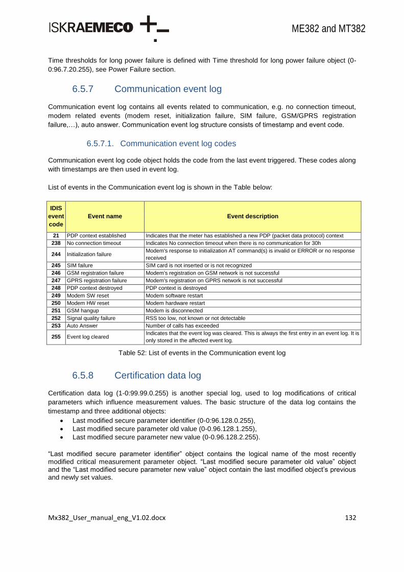
Mx382_User_manual_eng_V1.02.docx 132
ME382 and MT382
Time thresholds for long power failure is defined with Time threshold for long power failure object (0-
0:96.7.20.255), see Power Failure section.
6.5.7 Communication event log
Communication event log contains all events related to communication, e.g. no connection timeout,
modem related events (modem reset, initialization failure, SIM failure, GSM/GPRS registration
failure,…), auto answer. Communication event log structure consists of timestamp and event code.
6.5.7.1. Communication event log codes
Communication event log code object holds the code from the last event triggered. These codes along
with timestamps are then used in event log.
List of events in the Communication event log is shown in the Table below:
IDIS
event
code
Event name Event description
21 PDP context established Indicates that the meter has established a new PDP (packet data protocol) context
238 No connection timeout Indicates No connection timeout when there is no communication for 30h
244 Initialization failure Modem's response to initialization AT command(s) is invalid or ERROR or no response
received
245 SIM failure SIM card is not inserted or is not recognized
246 GSM registration failure Modem's registration on GSM network is not successful
247 GPRS registration failure Modem's registration on GPRS network is not successful
248 PDP context destroyed PDP context is destroyed
249 Modem SW reset Modem software restart
250 Modem HW reset Modem hardware restart
251 GSM hangup Modem is disconnected
252 Signal quality failure RSS too low, not known or not detectable
253 Auto Answer Number of calls has exceeded
255 Event log cleared Indicates that the event log was cleared. This is always the first entry in an event log. It is
only stored in the affected event log.
Table 52: List of events in the Communication event log
6.5.8 Certification data log
Certification data log (1-0:99.99.0.255) is another special log, used to log modifications of critical
parameters which influence measurement values. The basic structure of the data log contains the
timestamp and three additional objects:
Last modified secure parameter identifier (0-0:96.128.0.255),
Last modified secure parameter old value (0-0.96.128.1.255),
Last modified secure parameter new value (0-0.96.128.2.255).
“Last modified secure parameter identifier” object contains the logical name of the most recently modified critical measurement parameter object. “Last modified secure parameter old value” object and the “Last modified secure parameter new value” object contain the last modified object‟s previous and newly set values.

Mx382_User_manual_eng_V1.02.docx 133
ME382 and MT382
Capture to this log is done when one of the critical measurement parameters changes. In this case, all
the needed information (logical name, old value and new value) are stored in dedicated objects first
and then captured into certification data log.
The following critical parameters are being monitored:
Active energy metrological LED (1-0:0.3.0.255),
Reactive energy metrological LED (1-0:0.3.1.255),
Apparent energy metrological LED (1-0:0.3.2.255),
Transformer ratio – current (numerator) (1-0:0.4.2.255),
Transformer ratio – current (denominator) (1-0:0.4.5.255),
Measurement period 1, for average value 1 (1-0:0.8.0.255). The capacity of the Certification data log is set to 100 entries. When log is full, the critical measurement objects can no longer be changed. All change requests are rejected. The log can only be erased when meter is in unlocked state. This can only be achieved by removing meter cover.
6.5.9 Disconnector control log
IDIS
event
code
Event name Event description
59 Disconnector ready for manual
reconnection
Indicates that the disconnector has been set into the Ready for reconnection state and
can be manually reconnected
60 Manual disconnection Indicates that the disconnector has been manually disconnected.
61 Manual connection Indicates that the disconnector has been manually connected.
62 Remote disconnection Indicates that the disconnector has been remotely disconnected.
63 Remote connection Indicates that the disconnector has been remotely connected.
64 Local disconnection Indicates that the disconnector has been locally disconnected
65 Limiter threshold exceeded Indicates that the limiter threshold has been exceeded.
66 Limiter threshold ok Indicates that the monitored value of the limiter dropped below the threshold.
67 Limiter threshold changed Indicates that the limiter threshold has been changed
68 Disconnect/Reconnect failure Indicates that the a failure of disconnection or reconnection has happened
69 Local reconnection Indicates that the disconnector has been locally re-connected (i.e. via the limiter or
current supervision monitors).
70 Supervision monitor 1 threshold
exceeded Indicates that the supervision monitor threshold has been exceeded.
71 Supervision monitor 1 threshold
ok Indicates that the monitored value dropped below the threshold.
72 Supervision monitor 2 threshold
exceeded Indicates that the supervision monitor threshold has been exceeded.
73 Supervision monitor 2 threshold
ok Indicates that the monitored value dropped below the threshold.
74 Supervision monitor 3 threshold
exceeded Indicates that the supervision monitor threshold has been exceeded.
75 Supervision monitor 3 threshold
ok Indicates that the monitored value dropped below the threshold.
255 Event log cleared Indicates that the event log was cleared. This is always the first entry in an event log. It
is only stored in the affected event log.
Table 53: List of events in the Disconnector control log

Mx382_User_manual_eng_V1.02.docx 134
ME382 and MT382
6.5.10 M-Bus event log
IDIS
event
code
Event name Event description
100 Comm. error M-Bus Ch. 1 Indicates com. problem when reading the meter connected to Ch.1 of the M-Bus
101 Comm. ok M-Bus Ch.1 Indicates that the communication with the M-Bus meter connected to Ch.1 of the
M-Bus is ok again.
102 Replace Battery M-Bus Ch. 1 Indicates that the battery must be exchanged due to the expected end of life time.
103 Fraud attempt M-Bus Ch.1 Indicates that a fraud attempt has been registered.
104 Clock adjusted M-Bus Ch. 1 Indicates that the clock has been adjusted.
105 New M-Bus device installed Ch. 1 Indicated the meter (M-Bus master) has registered a M-Bus device connected to
channel 1 with a new serial number (2)
106 New M-Bus device installed Ch. 1 Indicated the meter (M-Bus master) has registered a M-Bus device connected to
channel 1 with a new serial number (2)
110 Communication Error M-Bus Ch. 2 Indicates com. problem when reading the meter connected to Ch.2 of the M-Bus
111 Comm. ok M-Bus Ch. 2 Indicates that the communication with the M-Bus meter connected to channel 2 of
the M-Bus is ok again.
112 Replace Battery M-Bus Ch. 2 Indicates that the battery must be exchanged due to the expected end of life time.
113 Fraud attempt M-Bus Ch. 2 Indicates that a fraud attempt has been registered.
114 Clock adjusted M-Bus Ch. 2 Indicates that the clock has been adjusted.
115 New M-Bus device installed Ch. 2 Indicated the meter (M-Bus master) has registered a M-Bus device connected to
channel 2 with a new serial number (2)
116 Permanent Error M-Bus Ch. 2 Severe error reported by M-Bus device (2)
120 Comm. Error M-Bus Ch. 3 Indicates com. problem when reading the meter connected to Ch.3 of the M-Bus
121 Comm. ok M-Bus Ch. 3 Indicates that the communication with the M-Bus meter connected to Ch.3 of the
M-Bus is ok again.
122 Replace Battery M-Bus Ch. 3 Indicates that the battery must be exchanged due to the expected end of life time.
123 Fraud attempt M-Bus Ch. 3 Indicates that a fraud attempt has been registered.
124 Clock adjusted M-Bus Ch. 3 Indicates that the clock has been adjusted.
125 New M-Bus device installed Ch. 3 Indicated the meter (M-Bus master) has registered a M-Bus device connected to
channel 3 with a new serial number (2)
126 Permanent Error M-Bus Ch. 3 Severe error reported by M-Bus device (2)
130 Comm. Error M-Bus Ch. 4 Indicates com. problem when reading the meter connected to Ch.4 of the M-Bus
131 Comm. ok M-Bus Ch. 4 Indicates that the communication with the M-Bus meter connected to ch.4 of the
M-Bus is ok again.
132 Replace Battery M-Bus Ch. 4 Indicates that the battery must be exchanged due to the expected end of life time.
133 Fraud attempt M-Bus Ch. 4 Indicates that a fraud attempt has been registered.
134 Clock adjusted M-Bus Ch. 4 Indicates that the clock has been adjusted.
135 New M-Bus device installed Ch. 4 Indicated the meter (M-Bus master) has registered a M-Bus device connected to
channel 4 with a new serial number (2)
136 Permanent Error M-Bus Ch. 4 Severe error reported by M-Bus device (2)
254 Load profile cleared
Any of the profiles cleared.
NOTE: If it appears in Standard Event Log then any of the E-load profiles was
cleared. If the event appears in the M-Bus Event log then one of the M-Bus load
profiles was cleared
255 Event log cleared Indicates that the event log was cleared. This is always the first entry in an event
log. It is only stored in the affected event log.
(2) Events included in IDIS Package 2
Table 54: List of events in the M-Bus event log

Mx382_User_manual_eng_V1.02.docx 135
ME382 and MT382
6.5.11 M-Bus control logs
IDIS
event
code
Event name Event description
160 Manual disconnection M-Bus Ch.1 Indicates that the disconnector has been manually disconnected
161 Manual connection M-Bus Ch.1 Indicates that the disconnector has been manually connected
162 Remote disconnection M-Bus Ch.1 Indicates that the disconnector has been remotely disconnected
163 Remote connection M-Bus Ch.1 Indicates that the disconnector has been remotely connected
164 Valve alarm M-Bus Ch. 1 Indicates that a valve alarm has been registered
165 Local disconnection M-Bus Ch. 1 Indicates that the disconnector has been locally disconnected (2)
166 Local connection M-Bus Ch. 1 Indicates that the disconnector has been locally connected (2)
170 Manual disconnection M-Bus Ch.2 Indicates that the disconnector has been manually disconnected
171 Manual connection M-Bus Ch.2 Indicates that the disconnector has been manually connected
172 Remote disconnection M-Bus Ch.2 Indicates that the disconnector has been remotely disconnected
173 Remote connection M-Bus Ch.2 Indicates that the disconnector has been remotely connected
174 Valve alarm M-Bus Ch. 2 Indicates that a valve alarm has been registered
175 Local disconnection M-Bus Ch. 2 Indicates that the disconnector has been locally disconnected (2)
176 Local connection M-Bus Ch. 2 Indicates that the disconnector has been locally connected (2)
180 Manual disconnection M-Bus Ch.3 Indicates that the disconnector has been manually disconnected
181 Manual connection M-Bus Ch.3 Indicates that the disconnector has been manually connected
182 Remote disconnection M-Bus Ch.3 Indicates that the disconnector has been remotely disconnected
183 Remote connection M-Bus Ch.3 Indicates that the disconnector has been remotely connected
184 Valve alarm M-Bus Ch.3 Indicates that a valve alarm has been registered
185 Local disconnection M-Bus Ch. 3 Indicates that the disconnector has been locally disconnected (2)
186 Local connection M-Bus Ch. 3 Indicates that the disconnector has been locally connected (2)
190 Manual disconnection M-Bus Ch.4 Indicates that the disconnector has been manually disconnected
191 Manual connection M-Bus Ch.4 Indicates that the disconnector has been manually connected
192 Remote disconnection M-Bus Ch.4 Indicates that the disconnector has been remotely disconnected
193 Remote connection M-Bus Ch.4 Indicates that the disconnector has been remotely connected
194 Valve alarm M-Bus Ch.4 Indicates that a valve alarm has been registered
195 Local disconnection M-Bus Ch. 4 Indicates that the disconnector has been locally disconnected (2)
196 Local connection M-Bus Ch. 4 Indicates that the disconnector has been locally connected (2)
255 Event log cleared Indicates that the event log was cleared. This is always the first entry in an event log.
It is only stored in the affected event log.
(2) Events included in IDIS Package 2
Table 55: List of events in the M-Bus control log
6.6. Alarms
When some special events occur in meter, internal alarm is generated in meter which can be sent to
the central system. The alarm parameters are predefined. The priority levels of alarms are adjustable.
Alarms are then registered and handled by the utility HES.

Mx382_User_manual_eng_V1.02.docx 136
ME382 and MT382
Figure 90: Alarm reporting process
Each bit in the alarm register represents a different alarm. If any bit is set, corresponding alarm was
recorded. Value of the alarm register is a 32-bit value of all active and inactive alarms. Depending on
the capabilities of the HES and the utility policy it is possible to mask unwanted alarms through the
alarm filter.
6.6.1 Alarm system
Mx382 meters support three different alarm system codes (active after PD/PU procedure):
VDEW / IE - (0),
IDIS - (1),
EDF - (2).
6.6.2 Alarm codes
Bit Alarm Description
0 Clock invalid Current clock is compared with internal clock structure and if there is any deviation the bit is set.
1 Replace battery Clock battery or backup capacitor is discharged.
2 A2*
3 A3*
4 A4*
5 A5*
6 Reserved for future use
7 Reserved for future use
8 Program memory error Set whenever a program memory error bit in error register is set.
9 RAM error Set whenever a RAM error bit in error register is set.
10 NV memory error Set whenever a NV memory error bit in error register is set.
11 Measurement system error Set whenever a measurement system error bit in error register is set.
12 Watchdog error Set whenever a watchdog error bit in error register is set.
13 Fraud attempt Set when fraud attempt is detected.
14 Reserved for future use
15 Reserved for future use
16 Comm. error M-Bus Ch1 M-Bus device connected to the channel 1 does not respond.
17 Comm. error M-Bus Ch2 M-Bus device connected to the channel 2 does not respond.
18 Comm. error M-Bus Ch3 M-Bus device connected to the channel 3 does not respond.

Mx382_User_manual_eng_V1.02.docx 137
ME382 and MT382
19 Comm. error M-Bus Ch4 M-Bus device connected to the channel 4 does not respond.
20 Fraud attempt M-Bus Ch1 Alarm is set when M-Bus device connected to the Ch. 1 reports a fraud attempt.
21 Fraud attempt M-Bus Ch2 Alarm is set when M-Bus device connected to the Ch. 2 reports a fraud attempt.
22 Fraud attempt M-Bus Ch3 Alarm is set when M-Bus device connected to the Ch. 3 reports a fraud attempt.
23 Fraud attempt M-Bus Ch4 Alarm is set when M-Bus device connected to the Ch. 4 reports a fraud attempt.
24 Reserved for future use
25 Reserved for future use
26 Reserved for future use
27 Reserved for future use
28 Reserved for future use
29 Reserved for future use
30 Reserved for future use
31 Reserved for future use
(*) Only valid for the PLC meters. Alarms A2 to A5 are mapped into bit3 to bit6. See “CIASE - Alarm Descriptor Service”.
Table 56: Alarm 1 codes (IDIS P1/P2)
Bit Alarm Description
0 Total Power Failure Set when power-down on meter occurs.
1 Power Resume Set when meter power returns.
2 Voltage Phase Failure L1 Set when voltage on at least L1 phase has fallen below the Umin threshold for longer
than time delay.
3 Voltage Phase Failure L2 Set when voltage on at least L2 phase has fallen below the Umin threshold for longer
than time delay.
4 Voltage Phase Failure L3 Set when voltage on at least L3 phase has fallen below the Umin threshold for longer
than time delay.
5 Voltage Phase Resume L1 Set when the mains voltage on L1 is in normal limits again.
6 Voltage Phase Resume L2 Set when the mains voltage on L2 is in normal limits again.
7 Voltage Phase Resume L3 Set when the mains voltage on L3 is in normal limits again.
8 Missing Neutral Set when the neutral connection from the supplier to the meter is interrupted.
9 Phase Asymmetry Set when large unbalance loads is present
10 Current Reversal Set when unexpected energy export is present (for energy import configured devices
only).
11 Wrong Phase Sequence Set when wrong mains connection or fraud (polyphase meters only).
12 Unexpected Consumption Set when consumption is detected on at least one phase when disconnector has been
disconnected.
13 Key Exchanged Set when one or more global keys changed.
14 Bad Voltage Quality L1 Set when L1 voltage is not within ranges for defined period of time (see
EN50160:2010, section 4.2.2).
15 Bad Voltage Quality L2 Set when L2 voltage is not within ranges for defined period of time (see
EN50160:2010, section 4.2.2).
16 Bad Voltage Quality L3 Set when L3 voltage is not within ranges for defined period of time (see
EN50160:2010, section 4.2.2).
17 External Alert Set when signal is detected on meter‟s INPUT terminal.
18 Local Communication Attempt Set when communication on any local port is detected (i.e. unauthorized access)
19 New M-Bus Device Installed
Ch1 Set when new M-Bus device is registered on the Ch1 with new serial number.
20 New M-Bus Device Installed
Ch2 Set when new M-Bus device is registered on the Ch2 with new serial number.
21 New M-Bus Device Installed
Ch3 Set when new M-Bus device is registered on the Ch3 with new serial number.
22 New M-Bus Device Installed
Ch4 Set when new M-Bus device is registered on the Ch4 with new serial number.
23 Reserved for future use

Mx382_User_manual_eng_V1.02.docx 138
ME382 and MT382
24 Reserved for future use
25 Reserved for future use
26 Reserved for future use
27 M-Bus Valve Alarm Ch1 Set when ALARM STATUS bit is received from device on Ch1.
28 M-Bus Valve Alarm Ch2 Set when ALARM STATUS bit is received from device on Ch2.
29 M-Bus Valve Alarm Ch3 Set when ALARM STATUS bit is received from device on Ch3.
30 M-Bus Valve Alarm Ch4 Set when ALARM STATUS bit is received from device on Ch4.
31 Disconnect/Reconnect Failure Set when disconnector failed to connect/disconnect.
Table 57: Alarm 2 codes (IDIS P2)
6.6.3 Alarm register
If any of the special events occurs, which triggers alarm, the corresponding flag in the alarm register is
set. All alarm flags in the alarm register remain active until the alarm register is cleared internally (by
device) or remotely (by client). Each bit in alarm register represents a different alarm. If any bit is set
(logical 1), alarm was recorded. Value in the register is a 32-bit value of all active and inactive alarms
at that time.
6.6.4 Alarm filter
Alarms can be masked through the Alarm Filter object. To mask out unwanted alarm, corresponding
bit (logical 0) in the alarm filter register must be cleared (unchecked). By default no alarm is enabled.
Structure of the Alarm filter is the same as structure of the Alarm register.
6.6.5 Alarm status
Alarm status register shows which alarm has been triggered. There is a separate register for the ON
and OFF statuses. Each bit represents the corresponding alarm. Recorded bit remains active until it is
cleared by the client. This registers cannot be cleared by the device. Structure of the Alarm status is
the same as the Alarm register.
6.6.6 Alarm descriptor
Whenever a bit in the Alarm Registers changes from 0 to 1, then the corresponding bit of the Alarm
Descriptors is set to 1. Resetting the Alarm Registers does not affect the Alarm Descriptors. The set
bits of the Alarm Descriptors can be reset explicitly by the client. Structure of the Alarm descriptor is
the same as the Alarm register.
6.6.7 Alarm monitor
Alarm monitor is a special implementation of the Register monitor functionality (according to the IDIS
P2 specification), which is used to trigger action up, when any new alarm occurs in the meter. This is
monitored through the configured Alarm descriptor register as a monitored object.

Mx382_User_manual_eng_V1.02.docx 139
ME382 and MT382
6.7. Errors
The meter uses its automatic supervision mechanism to detect and log different types of events
related to meter operation. These events can be a part of meter's internal functionality or can occur
due to changes in the meter's environment. When an event which indicates a malfunction in meter
operation is triggered, the appropriate flag in the error register is set.
Once a flag in the Error register object (0-0:97.97.0.255) is set, it remains active even after the
corresponding error condition has disappeared. The Error register object has to be cleared manually
(using supported communication interfaces). If, after the flag in the error register has been cleared, the
corresponding error condition still remains, the flag in the error register is re-set by the meter.
During operation, the meter performs tests of individual functions. In case of an error it is represented with corresponding error bit in the Error Object register and FF flag on the LCD display is set. The Error Object value register is 32 bits long and is organized in 4 groups of errors:
Memory errors,
Communication errors,
Clock errors,
Control errors.
6.7.1 Error register
Mx382 meters contain two sets of error registers. First set is used to report errors with IDIS
specifications, while the second set is used for backward capability with other Iskraemeco AMI meters.
The table below gives an overview of all errors (IDIS errors codes) and their assignments.
Bit Error Description
0 Clock invalid Clock is invalid.
1 Replace battery (discharged) Clock battery or backup capacitor is discharged.
2-7 Unused /
8 Program memory error
Indicates error in the meters program space (internal flash memory)
when the behavior of meter is unpredictable and the meter should be
replaced. The results stored in the meter should be inspected and
validated.
9 RAM error Error detected in RAM (data) memory. The meter can operate
irregularly.
10 NV memory error Error detected in non-volatile memory. The meter can operate
irregularly.
11 Measurement system error Error detected in measurement system. The measurement could be
inaccurate.
12 Watchdog error Meter has been restarted by watch-dog circuitry.
13-15 Unused /
16 Communication error M-Bus
channel 1 Communication with M-Bus device on channel 1 failed.
17 Communication error M-Bus channel 2
Communication with M-Bus device on channel 2 failed.
18 Communication error M-Bus channel 3
Communication with M-Bus device on channel 3 failed.

Mx382_User_manual_eng_V1.02.docx 140
ME382 and MT382
19 Communication error M-Bus channel 4
Communication with M-Bus device on channel 4 failed.
20-31 Unused /
Table 58: IDIS error codes register
The table below gives an overview of all errors (IE errors codes) and their assignments.
Bit Error Description
0-7 Unused
8 ROM checksum error
9 Back-up data checksum
10 Parameters checksum
11 Profile checksum
12 Event log checksum
13 RAM checksum
14-15 Unused
16 RAM error Error detected in RAM (data) memory. The meter can operate
irregularly.
17 FRAM memory error Error detected in non-volatile memory. The meter can operate
irregularly
18 Measurement error
19 RTC error
20-21 Unused
22 Communication error
23 Display error
24 Battery discharged Clock battery or backup capacitor is discharged.
25 Invalid time Clock is invalid.
26-31 Unused
Table 59: IE error codes register
6.7.2 Error filter
Depending on the capabilities of the system and the policy of the utility, not all possible errors are desired. Therefore the error filter object can be programmed to mask out unwanted errors. The structure of the Error 1 filter object (0-0:196.97.0.255) is the same as the structure of the Error register object (0-0:97.97.0.255). To mask out unwanted errors the corresponding bit in the error filter should be set to logical 1.
Figure 91: Error filtering

Mx382_User_manual_eng_V1.02.docx 141
ME382 and MT382
6.7.3 Error display filter
With this objects errors can be filtered out on display FF flag. In order to filter out the right error the
corresponding bit in the error display filter should be set to logical 1.
6.7.4 Error types
Errors recorded in the Error register object (0-0:97.97.0.255) fall into one of five categories:
Clock errors,
Memory errors,
Measurement system error,
Communication errors,
Control errors.
6.7.4.1. Clock errors
Invalid clock error Current clock is compared with internal clock structure and if there is any deviation error will be set.
When the meter clock is set the meter will reset invalid time bit in error register. The energy registers
are not affected by “Invalid time error”.
Check battery state error
The state of battery or real time backup capacitor is monitored continuously and if voltage level falls
under specified threshold an error is reported by setting Replace Battery Error flag.
6.7.4.2. Memory errors
Program memory error
Program memory is checked by integrity of program code stored. Program code is signed by MD5
algorithm during the build time. The signature is stored together with program code in program
memory. In the run time meter calculates signature over program code and compares it with
previously stored one. If signatures are different, Program Memory Error flag is set.
Due to substantial size of program memory, program memory checking runs as background task to
not affect normal execution of other program code. By continuous running any unpredicted changes in
program code can be detected and reported.
Data memory error
Complete data memory (RAM) is checked during initialization process of the meter, which is started
after power-up or firmware upgrade. During initialization procedure a meter performs test of RAM
through whole address range. The test is executed for every memory location and it is nondestructive.
The original content of memory location under test is loaded to the CPU register, and then inverted
content is stored to the same memory location and compared with inverted content stored in CPU
register. Upon successful comparison of the inverted content, the original content of memory location
is restored and compared with its copy sorted in CPU register at the beginning of the test. If test fails,
meter sets RAM Error flag.
Otherwise during the normal operation meter checks integrity data structures where critical data are
stored. Each time when such data structure is intentionally changed, new signature is calculated and
stored. Later on when data are accessed again by the program, the integrity can be checked by
comparing newly calculated signature with one calculated during last intentionally change. If

Mx382_User_manual_eng_V1.02.docx 142
ME382 and MT382
signatures do not match, meter sets RAM Error flag. In such way continuous monitoring of RAM is
achieved.
Non-Volatile memory error The non-volatile memory is used to retain the stored information even when a meter is not powered. It
is used as long-term persistent storage for periodical history data, billing data, event logs, register
back-up copies, parameters and any other data meter needs for normal start.
Data integrity checking is performed periodically or randomly during data access. Checking of data
which are results of meter processes and they are changing more often is done during data access.
The meter configuration parameters are checked periodically with period of one hour. If any of the
checks fails Non-volatile Memory in errors register is set.
6.7.4.3. Measurement system error
Check accuracy measurement error
Checking of undisturbed operation and accuracy of the meter, to certain extend, performs a meter by
itself. If any error is detected, meter reports it by setting Measurement System Error flag.
6.7.4.4. Communication errors
M-Bus Communication error Connection of meter with hosted M-Bus meter is checked during communication with M-Bus slave device. If there is no respond from a slave device or there is a respond but structure of the data frame on data link layer is incorrect, meter will set corresponding error bit.
6.7.4.5. Control errors
ROM Checksum error
Indicates error in the meters program space (micro-controller internal FLASH memory) when the
behavior of meter is unpredictable and meter should be replaced. The results stored in the meter
should be inspected and validate.
Backup Error
Indicates CRC error in FRAM for energy back-up data and every time when new copy is created meter
calculates CRC for it. Before use of such copy meter checks CRC and if CRC is not valid generates
“Backup Error”.
Parameter Error
Indicates checksum error in parameter storage (meters non-volatile memory). The error does not
affect energy cumulative registers but can affect tariff registers if an error is detected inside tariff
program. The error bit can be reset by writing new set of parameters.
Data Error Indicates CRC error for energy data stored in RAM and this error appears in combination with “Backup Error”. Since occurrence of that error results in the meter are not valid, the meter should be replaced.
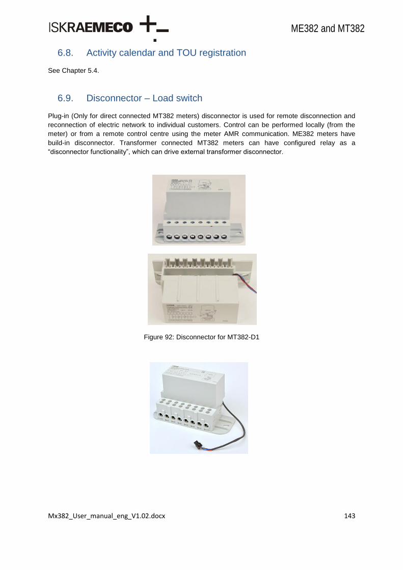
Mx382_User_manual_eng_V1.02.docx 143
ME382 and MT382
6.8. Activity calendar and TOU registration
See Chapter 5.4.
6.9. Disconnector – Load switch
Plug-in (Only for direct connected MT382 meters) disconnector is used for remote disconnection and
reconnection of electric network to individual customers. Control can be performed locally (from the
meter) or from a remote control centre using the meter AMR communication. ME382 meters have
build-in disconnector. Transformer connected MT382 meters can have configured relay as a
“disconnector functionality”, which can drive external transformer disconnector.
Figure 92: Disconnector for MT382-D1

Mx382_User_manual_eng_V1.02.docx 144
ME382 and MT382
Figure 93: Disconnector for MT382-D2
Figure 94: MT382 meter with disconnector
Disconnect and reconnect can be requested:
Remotely, via a communication channel: remote disconnect, remote reconnect,
Manually, using e.g. a Scroll key: manual disconnect, manual reconnect,
Locally, by a function of the meter (e.g. limiter, register monitor): local disconnect, local reconnect.
The state diagram and the possible state transitions are shown in the figure below:

Mx382_User_manual_eng_V1.02.docx 145
ME382 and MT382
Figure 95: Disconnect state control diagram
Table below shows and describes all available disconnector transitions.
Transition Transition name Description
a Remote
reconnect
Moves the Disconnect control object from the Disconnected (0) state directly to the
Connected (1) state without manual intervention
b Remote
disconnect
Moves the Disconnect control object from the Connected (1) state to the
Disconnected (0) state
c Remote
disconnect
Moves the Disconnect control object from the Ready for reconnection (2) state to
the Disconnected (0) state
d Remote
reconnect
Moves the Disconnect control object from the Disconnected (0) state to the Ready
for reconnection (2) state. From this state, it is possible to move to the Connected
(2) state via the manual reconnect transition (e)
e Manual
reconnect
Moves the Disconnect control object from the Ready for connection (2) state to the
Connected (1) state
f Manual
disconnect
Moves the Disconnect control object from the Connected (1) state to the Ready for
connection (2) state. From this state, it is possible to move back to the Connected
(2) state via the manual reconnect transition (e)
g Local disconnect
Moves the Disconnect control object from the Connected (1) state to the Ready for
connection (2) state. From this state, it is possible to move back to the Connected
(2) state via the manual reconnect transition (e). Transitions f) and g) are
essentially the same, but their trigger is different
h Local reconnect
Moves the Disconnect control object from the Ready for connection (2) state to the
Connected (1) state. Transitions e) and h) are essentially the same, but their
trigger is different.
Table 60: Disconnect transitions
Disconnector can not be in use as main network switch or fuse.
6.9.1 Disconnector type
With this object disconnector type can be selected. Available options are:
0 – None (disabled actions on disconnector),

Mx382_User_manual_eng_V1.02.docx 146
ME382 and MT382
1 – Disconnector (also called circuit breaker) OM31 or poly-phase ZO3xx unit or one phase build-in disconnect unit,
4 – Relay driven (external disconnect unit driven with relay).
For effective use of functionalities, meter must be properly configured.
6.9.2 Disconnect control
This object controls the connection and disconnection of the premises of the consumer.
Output State
Disconnect Output State shows the actual physical state of the disconnect unit.
FALSE – Open – Customer is disconnected from the network - (0),
TRUE – Closed – Customer is connected to the network - (1).
Control State Control State defines internal logical state of the disconnect unit. Possible control states are:
Disconnected – Customer is disconnected from the network - (0),
Connected – Customer is connected to the network - (1),
Ready for reconnection – Customer is disconnected from the network - (2). When disconnector is in Ready For Reconnection control state, it is possible to perform manual connect on the meter by holding the Scroll key until ConnEct is shown on display. Control Mode
Defines available transitions in Disconnect control class.
Mode Description 0 None. The disconnect control object is always in „connected‟ state
1
Disconnection:
Remote (b, c)
Manual (f) – Press and hold Scroll key till Disconnect appears and release the key
Local (g)
Reconnection: Remote (d)
Manual (e) – Press and hold the Scroll key till EntEr appears and release the key
2
Disconnection:
Remote (b, c)
Manual (f) – Press and hold Scroll key till Disconnect appears and release the key
Local (g)
Reconnection: Remote (a)
Manual (e) – Press and hold the Scroll key till EntEr appears and release the key
3
Disconnection: Remote (b, c)
Local (g)
Reconnection: Remote (d) Manual (e)
4
Disconnection: Remote (b, c)
Local (g)
Reconnection: Remote (a)
Manual (e) – Press and hold the Scroll key till EntEr appears and release
5
Disconnection:
Remote (b, c)
Manual (f) – Press and hold Scroll key till Disconnect appears and release the key
Local (g)
Reconnection: Remote (d)
Manual (e) – Press and hold the Scroll key till EntEr appears and release the key Local (h)

Mx382_User_manual_eng_V1.02.docx 147
ME382 and MT382
6
Disconnection: Remote (b, c)
Local (g)
Reconnection: Remote (d)
Manual (e) – Press and hold the Scroll key till EntEr appears and release the key Local (h)
Table 61: Disconnector modes
For effective use of functionalities, meter must be properly configured.
Depending on the mode selected, manual reconnection and
disconnection is possible by pressing the Scroll key.
Manual reconnection (all control modes): Display shows ConnEct. Press
the Scroll key for 5 seconds (until EntEr appears on the display) and
then release the key.
Manual disconnection (control modes: 1, 2, 5): Press the Scroll key for 10 seconds (until dISconn
appears on the display) and then release it.
The switchover can be also made remotely by executing remote disconnect or remote reconnect method. Transition change is described in Disconnect control IC state diagram (BB10ed, p.84).
For manual reconnection of the meter, which is placed in the meter cabinet, the non-potential external
key on the door of the cabinet can be used.
Method Description
Remote disconnect forces the disconnector into „disconnected‟ state if remote disconnection is enabled (control mode > 0).
Remote reconnect forces the disconnector into the „ready for reconnection‟ state if a direct remote reconnection is disabled (control mode = 1, 3, 5, 6) or into „connected‟ state‟ if a direct remote reconnection is enabled (control mode = 2, 4).
6.9.3 Disconnect control log
Contains all events related to the disconnector, e.g. connect, disconnect, changing of the disconnector threshold. Disconnect control log structure contains timestamp and event code. Disconnector control event log code object holds the code from the last event triggered. These codes along with timestamps are then used in event log. (See chapter 6.13.9)
6.10. Limitation
Beside collecting and processing energy consumption data, AMI system offers load balancing and
control. To achieve this current and demand limitation is implemented in the meter. During short time
period when power consumption excides contractual value for a specified time interval, customer is
disconnected from the grid until normal conditions are achieved or when penalty time is over.
Mx382_User_manual_eng_V1.02.docx 148
ME382 and MT382
To handle consumption monitoring and disconnection of customer premises, following principles are
used:
Phase current measurement,
Disconnection separation between disconnector and main fuse,
Threshold level settings in accordance with customer contract and local regulator rules.
A disconnector is only disconnection element, all measurements, supervision of measured quantities
is handled by AMI meter.
The meter supports two different limitation types: Limiter and Supervision monitor. Supervision monitor
supports both:
IDIS definition implementation (average phase current monitoring),
GIZ definition implementation (instantaneous phase current monitoring with penalty timers).
For effective use of functionalities, meter must be properly configured.
6.10.1 Limiter
Limiter functions are used to monitor electrical network for exceeding maximum energy (power) in
predefined period of time. Limiter object handles normal current and instantaneous power monitoring
as well as the emergency settings. Meter supports two limiter objects.
The customer can (after correcting the exceeding level) reconnect network manually (by pressing the
Scroll key on the meter) or with remote connection (depending on the disconnector mode used).
For effective use of functionalities, meter must be properly configured.
The threshold value can be normal or emergency threshold. The emergency threshold is activated via
the emergency profile defined by emergency profile id, activation start time, and duration. The
emergency profile id element is matched to an emergency profile group ID: this mechanism enables
the activation of the emergency threshold only for a specific emergency group.
The limitation or disconnection functionality can be activated in the meter itself or by remote action. The meter disconnects the network (via disconnector) if a maximum current or power limit has exceeded during a predefined period of time. The current or power levels with the allowed exceeding periods are set in the meter.

Mx382_User_manual_eng_V1.02.docx 149
ME382 and MT382
Normal limit
Emergency limit
td - Min. over treshold durationEmergency activation
Customer activation (blue button or remote)
Emergency limit activation duration
Disconnected
Consumption
tdtd
Figure 96: Limiter diagram
Instances of the Limiter interface class allows set of actions which are executed when the value of a
monitored object attribute “Data”, “Register”, “Extended Register”, “Demand Register”, etc. crosses the
threshold value for at least a minimal duration time.
IDIS defines only one limiter object instance. Iskraemeco meters have two limiter instances (0-0:17.0.0
and 0-0:17.0.1).
Monitored Value
Monitored value defines an attribute of an object to be monitored. Only attributes with simple data
types are allowed. Instantaneous current (example for three-phase meters is object 1-0:90.7.0
(Algebraic sum L1, L2 & L3 current), or sliding demand average import/net power (1-0:1.24.0, 1-
0:15.24.0).
Threshold Active
Provides the active threshold value to which the attribute monitored is compared.
Threshold Normal
Provides the threshold value to which the attribute monitored is compared when in normal operation.
Threshold Emergency
Provides the threshold value to which the attribute monitored is compared when an emergency profile
is active.
Minimum over Threshold Duration
Defines minimal over threshold duration in seconds required to execute the over threshold action.
Minimum under Threshold Duration
Defines minimal under threshold duration in seconds required to execute the under threshold action.
Emergency Profile
An emergency profile is defined by three elements:
emergency profile ID,
emergency activation time,
emergency duration.

Mx382_User_manual_eng_V1.02.docx 150
ME382 and MT382
An emergency profile is activated if the emergency profile ID element matches one of the elements on
the emergency profile group ID list, and time matches the emergency activation time and emergency
duration element:
Emergency activation time defines the date and time when the emergency profile is activated.
Emergency duration defines the duration in seconds, for which the emergency profile is activated.
When an emergency profile is active, the emergency profile active attribute is set to TRUE.
Emergency Profile Group ID List It defines a list of group IDs of the emergency profile. The emergency profile can be activated only if
emergency profile ID element of the emergency profile type matches one of the elements on the
emergency profile group ID list.
Emergency Profile Active
It indicates that the emergency profile is active.
False - (0),
True - (1). Actions
It defines the script to be executed when the monitored value crosses the threshold for minimal
duration time.
Action over threshold defines the action when the value of the attribute monitored crosses the threshold in upwards direction and remains over threshold for minimal over threshold duration time;
(0-0:10.0.106, 1; 0-0:10.0.106, 2)
Action under threshold defines the action when the value of the attribute monitored crosses the threshold in the downwards direction and remains under threshold for minimal under threshold duration time.
(0-0:10.0.106, 0; 0-0:10.0.106, 1)
6.10.2 Supervision monitor - IDIS
Mx382 meter features phase current limitation with three RM objects. Every RM monitors the
corresponding phase demand register. Actions that need to be taken are defined via the Disconnector
script table object, where action on Disconnect control object is defined.
When monitored value passes threshold upwards or downwards, action up or action down is taken.
For Mx382 meters, there is only one threshold allowed to be set, because of the limitation functionality.
IDIS specifies objects 1-0:31.4.0, 1-0:51.4.0 and 1-0:71.4.0 for a monitored value. This is not directly
measured phase current RMS, but the averaged value over the number of periods, which is defined
with demand class object instance for every phase. Phase RMS current is averaged with period (1
second) and number of periods (90) values. Value has a 1A resolution rounded down.
6.10.2.1. Register monitor – Monitored value
Current Average Value
This attribute provides the current average value of the current.

Mx382_User_manual_eng_V1.02.docx 151
ME382 and MT382
Last Average Value
Provides the last average value of the current (over the last number of periods*period) divided by
number of periods*period.
Status
This attribute provides “Demand register” specific status information.
Capture Time
Provides the date and time when the last average value has been calculated. Octet-string, formatted
as set in 4.1.6.1 for date time.
Start Time Current
Provides the date and time when the measurement of the current average value has been started.
Octet-string, formatted as set in 4.1.6.1 for date time.
Period
Period is the interval between two successive updates of the last average value. Measuring period is
in seconds.
For effective use of functionalities, meter must be properly configured.
Number of Periods
The number of periods used to calculate the last average value.
6.10.2.2. Register monitor instance
Thresholds This attribute provides threshold values with which the attribute of the referenced register is compared.
The threshold is the same type as the monitored attribute of the referenced object.
For effective use of functionalities, meter must be properly configured.
Monitored Value
Defines an object of specific class and it's attribute to be monitored. IDIS specifications require one of
the next available objects with IC 5, attr. 2: 1-0:31.4.0, 1-0:51.4.0 and 1-0:71.4.0.
For effective use of functionalities, meter must be properly configured.
Actions
This attribute defines scripts to be executed when the monitored attribute of the referenced object
crosses the corresponding threshold. The attribute “actions” has exactly the same number of elements
as the attribute “thresholds”. The action items order corresponds to the thresholds (see above values
order) where:

Mx382_User_manual_eng_V1.02.docx 152
ME382 and MT382
action up defines the action when the attribute value of the monitored register crosses the threshold in the upwards direction
(0-0:10.0.106, 1; 0-0:10.0.106, 2),
action down defines the action when the attribute value of the monitored register crosses the threshold in the downwards direction
(0-0:10.0.106, 1; 0-0:10.0.106, 0).
Abbreviations:
RM – register monitor,
TEE – threshold exceeding event,
TOE – threshold OK event,
OTD – over threshold duration.
6.10.3 Supervision monitor - GIZ
The meter features phase current limitation with three RM objects. Every RM monitors the
corresponding phase current instantaneous value. The actions that need to be taken are defined via
the Disconnector script table object, where action on Disconnect control object is defined.
The functionality of the register monitor is affected with two manufacturer specific objects “Over
threshold duration” and “Manual Reconnection penalty time”.
6.10.3.1. Register monitor
Thresholds
Provides the threshold values to which the attribute of the referenced register is compared. The
threshold is of the same type as the monitored attribute of the referenced object.
For effective use of functionalities, meter must be properly configured.
Monitored Value
Defines an object of specific class and it's attribute to be monitored. GIZ specifications require next
objects: 1-0:31.7.0, 1-0:51.7.0 and 1-0:71.7.0.
For effective use of functionalities, meter must be properly configured.
Actions
This attribute defines the scripts to be executed when the monitored attribute of the referenced object
crosses the corresponding threshold. The attribute “actions” has exactly the same number of elements
as the attribute “thresholds”. The ordering of the action items corresponds to the ordering of the
thresholds (see above) where:
action up defines the action when the attribute value of the monitored register crosses the threshold in the upwards direction (0-0:10.0.106, 1; 0-0:10.0.106, 2),
action down defines the action when the attribute value of the monitored register crosses the threshold in the downwards direction (0-0:10.0.106, 1; 0-0:10.0.106, 0).

Mx382_User_manual_eng_V1.02.docx 153
ME382 and MT382
6.10.3.2. Over threshold duration
Defines the maximum duration in seconds, how long can monitored value stay over the threshold
level, before disconnect occurs.
For effective use of functionalities, meter must be properly configured.
6.10.3.3. Manual reconnection penalty time
Defines the minimum duration in seconds, how long we have to wait after the disconnect action,
before we can reconnect again.
Example 1: monitoring phase current with constant threshold parameter
Figure 97: Monitoring phase current with constant threshold parameter
[1] – RM detects action up. TEE for monitored register is generated in a Control log.
[2] – RM detects action down. Duration is less than OTD time tb - ta < 90 sec. “Threshold OK” event for monitored register is generated in a Control log.
[3] – RM detects action up. TEE for monitored register is generated in a Control log.
[4] – RM detects time over threshold td - tc = 90 sec. Local disconnect transition (g) occurs and the disconnector disconnects. Disconnect event is generated in a Control log.
[5] – RM detects action down. Because the reason for this is [4], no “Threshold OK” event is generated in a Control log.
[6] – Console status “connect” is displayed. Penalty timer starts.
[7] – After RPT is over te - td > 60 sec, it is possible to reconnect the disconnector again.
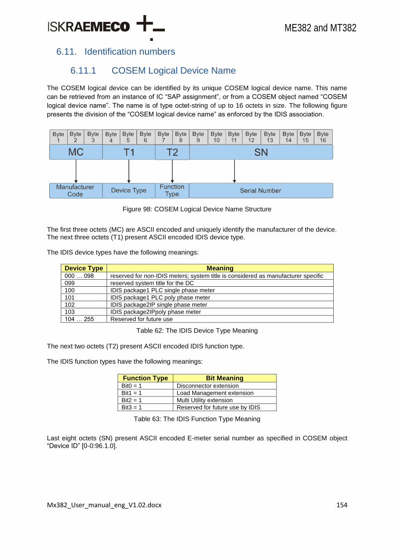
Mx382_User_manual_eng_V1.02.docx 154
ME382 and MT382
6.11. Identification numbers
6.11.1 COSEM Logical Device Name
The COSEM logical device can be identified by its unique COSEM logical device name. This name
can be retrieved from an instance of IC “SAP assignment”, or from a COSEM object named “COSEM
logical device name”. The name is of type octet-string of up to 16 octets in size. The following figure
presents the division of the “COSEM logical device name” as enforced by the IDIS association.
Figure 98: COSEM Logical Device Name Structure
The first three octets (MC) are ASCII encoded and uniquely identify the manufacturer of the device. The next three octets (T1) present ASCII encoded IDIS device type. The IDIS device types have the following meanings:
Device Type Meaning 000 … 098 reserved for non-IDIS meters; system title is considered as manufacturer specific
099 reserved system title for the DC
100 IDIS package1 PLC single phase meter
101 IDIS package1 PLC poly phase meter
102 IDIS package2IP single phase meter
103 IDIS package2IPpoly phase meter
104 … 255 Reserved for future use
Table 62: The IDIS Device Type Meaning
The next two octets (T2) present ASCII encoded IDIS function type. The IDIS function types have the following meanings:
Function Type Bit Meaning Bit0 = 1 Disconnector extension
Bit1 = 1 Load Management extension
Bit2 = 1 Multi Utility extension
Bit3 = 1 Reserved for future use by IDIS
Table 63: The IDIS Function Type Meaning
Last eight octets (SN) present ASCII encoded E-meter serial number as specified in COSEM object “Device ID” [0-0:96.1.0].
Mx382_User_manual_eng_V1.02.docx 155
ME382 and MT382
For effective use of functionalities, meter must be properly configured.
Example of the COSEM logical device name for Iskraemeco‟s ME382 meter with disconnector, multi-utility and load management functionality with the Device ID 00000001:
MC T1 T2 SN Octet01
Octet02
Octet03
Octet04
Octet05
Octet06
Octet07
Octet08
Octet09
Octet10
Octet11
Octet12
Octet13
Octet14
Octet15
Octet16
I S K 1 0 2 0 7 0 0 0 0 0 0 0 1
Table 64: COSEM logical device name example 1
6.11.2 System title
System title is tightly coupled with the COSEM logical device name. The relation between both entities is as follows:
System title is eight (8) octets in size while the COSEM logical device name is sixteen (16) octets in size. Thus the transformation is:
MC is three (3) octets long,
T1 is one (1) octet long and HEX encoded,
T2 is half octet long (four MSB bits) and HEX encoded,
SN is three and a half octets long and HEX encoded.
Example of the COSEM logical device name for Iskraemeco‟s ME382 meter with disconnector, multi-utility and load management functionality with the Device ID 00000001:
Octet01 Octet02 Octet03 Octet04 Octet05 Octet6 Octet07 Octet08
MC T1 T2 SN Sn SN SN
ISK 66 70 0 0 1
Table 65: COSEM logical device name example 2
6.11.3 Device number
Device number is unique meter number in certain group of meters. The number is ASCII encoded. The length of the ID must be eight (8) octets.
The number is copied into IEC local port setup object (0-0:20.0.0) and is used when accessing the meter through IEC 61056-21 (former 1107) protocol.
For effective use of functionalities, meter must be properly configured.
6.11.4 Device ID
Meter has nine different device ID‟s:
Device ID 1 – E-Meter serial number (e=0),

Mx382_User_manual_eng_V1.02.docx 156
ME382 and MT382
Device ID 2 – E-Meter equipment ID (e=1),
Device ID 3 – function location (e=2),
Device ID 4 – location information (e=3),
Device ID 5 – general purpose (e=4),
Device ID 6 – (e=5),
Device ID 7 – (e=6),
Device ID 8 – (e=7),
Device ID 9 – meter ID (e=8).
6.11.4.1. Device ID 1
Device ID1 is E-meter factory serial number (also reflected in a COSEM logical device name). The number is ASCII encoded. The length of the ID must be eight (8) octets.
For effective use of functionalities, meter must be properly configured.
6.11.4.2. Device ID 2
Device ID2 is customer ID. The number is ASCII encoded. The length of the ID must not exceed forty eight (48) octets.
6.11.4.3. Device ID 3
Device ID3 represents function location. The number is ASCII encoded. The length of the ID must not exceed forty eight (48) octets.
6.11.4.4. Device ID 4
Device ID4 includes location information. The number is ASCII encoded. The length of the ID must not exceed forty eight (48) octets.
6.11.4.5. Device ID 5
Device ID5 has no special meaning defined. It is general purpose ID for any identification purposes. The number is ASCII encoded. The length of the ID must not exceed forty eight (48) octets.
6.11.4.6. Device ID 6
Device ID 6 is IDIS certification number. The number is ASCII encoded. The length of the ID must not exceed forty eight (48) octets.
6.11.4.7. Device ID 7 .. Device ID 9
The length of the ID must not exceed forty eight (48) octets.
6.11.5 Medium specific ID
M-Bus device id‟s are described under M-Bus Section: M-Bus identification numbers.

Mx382_User_manual_eng_V1.02.docx 157
ME382 and MT382
6.11.6 Meter software identification
This chapter describes metering application FW identification for electric energy meter types Mx382.
6.11.6.1. Software architecture
The main parts of the basic modular division of software for the Mx382 meters are:
platform,
core interface,
module.
“Platform” and “core interface” constitute a concluded entity called CORE, while application module
represents MODULE. Each of two entities has its own parameters that can be configured at build time
(adjustable in time of code translation) or at configuration time in factory. Nevertheless only MODULE has
specific parameters that are variable during operation.
E-meters versioning control
Due to legal constraints meter‟s firmware is divided into two modules. The first is application core and the second is application module. Both entities have their own identification string and signature.
E-meter identification strings
Meter‟s identification strings are divided into two subsets of sixteen (16) characters. First subset represents application core while second represents application module identification. The identification for both entities is organized as follows.
Figure 99: Identification Structure
Manufacturer tag – ISK stands for Iskraemeco (3 characters),
SW tag – (2 characters),
Device type – (5 characters),
Revision – Revision of application core or application module (6 characters).
The revision number field is organized as follows:
Figure 100: Revision Number Structure
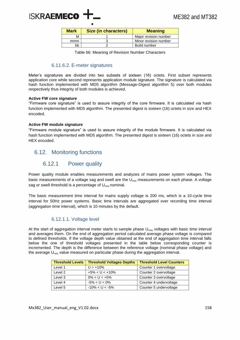
Mx382_User_manual_eng_V1.02.docx 158
ME382 and MT382
Mark Size (in characters) Meaning
M 1 Major revision number
mmm 3 Minor revision number
bb 2 Build number
Table 66: Meaning of Revision Number Characters
6.11.6.2. E-meter signatures
Meter‟s signatures are divided into two subsets of sixteen (16) octets. First subset represents application core while second represents application module signature. The signature is calculated via hash function implemented with MD5 algorithm (Message-Digest algorithm 5) over both modules respectively thus integrity of both modules is achieved.
Active FW core signature
“Firmware core signature” is used to assure integrity of the core firmware. It is calculated via hash
function implemented with MD5 algorithm. The presented digest is sixteen (16) octets in size and HEX
encoded.
Active FW module signature
“Firmware module signature” is used to assure integrity of the module firmware. It is calculated via
hash function implemented with MD5 algorithm. The presented digest is sixteen (16) octets in size and
HEX encoded.
6.12. Monitoring functions
6.12.1 Power quality
Power quality module enables measurements and analyzes of mains power system voltages. The
basic measurements of a voltage sag and swell are the Urms measurements on each phase. A voltage
sag or swell threshold is a percentage of Urms nominal.
The basic measurement time interval for mains supply voltage is 200 ms, which is a 10-cycle time
interval for 50Hz power systems. Basic time intervals are aggregated over recording time interval
(aggregation time interval), which is 10 minutes by the default.
6.12.1.1. Voltage level
At the start of aggregation interval meter starts to sample phase Urms voltages with basic time interval and averages them. On the end of aggregation period calculated average phase voltage is compared to defined thresholds. If the voltage depth value obtained at the end of aggregation time interval falls below the one of threshold voltages presented in the table below corresponding counter is incremented. The depth is the difference between the reference voltage (nominal phase voltage) and the average Urms value measured on particular phase during the aggregation interval.
Threshold Levels Threshold Voltages Depths Threshold Level Counters
Level 1 U > +10% Counter 1 overvoltage
Level 2 +5% < U < +10% Counter 2 overvoltage
Level 3 0% < U < +5% Counter 3 overvoltage
Level 4 -5% < U < 0% Counter 4 undervoltage
Level 5 -10% < U < -5% Counter 5 undervoltage

Mx382_User_manual_eng_V1.02.docx 159
ME382 and MT382
Level 6 -15% < U > -10% Counter 6 undervoltage
Level 7 U < -15% Counter 7 undervoltage
Table 67: Dip & swell detection model
During the processing of the measurement at the end of aggregation interval in case of simultaneous
sags or swells corresponding phase threshold level counters and the common threshold levels
counters named ANY are incremented. In case when the voltage depths measured on more phases
are in the same threshold level corresponding ANY counter is incremented only by 1.
On each phase voltage is calculated every 10 minutes. Calculated is average voltage with sampling
made every 200ms in 10 minute aggregation period. As a result of this calculation, appropriate level
counter is incremented.
Nominal voltage (U) used in calculations is 230V. If calculated average voltage at the end of 10 min
period is under, over or in the range of certain percentage (see above table), than the appropriate
counter is incremented.
Example: The following Figure illustrates sampling and recording of an event: voltage sag. Figure
shows voltage dip from 9th sample to 22
nd sample. Average voltage of all samples is
shown with straight line. Average voltage value is also used to record appropriate event:
average voltage on picture is about 214 Volts, 7% sag of 230 Volts.
Figure 101a: Voltage sampling
Power quality voltage sampling example
200
205
210
215
220
225
230
235
1 3 5 7 9 11 13 15 17 19 21 23 25
Samples
Vrm
s

Mx382_User_manual_eng_V1.02.docx 160
ME382 and MT382
Figure 101b: Voltage sampling
6.12.1.2. Voltage sag
Voltage sags are recorded when voltage drops below “Threshold for Voltage Sag“ for the time set in
“Time Threshold for Voltage Sag“. Also recorded in designated objects are each sag in counter
objects, magnitude of voltage sags and duration of voltage sag.
All events are also recorded in “Power Quality Log“ as “undervoltage“ event. See Chapter 6.5.5.1.
As soon as voltage drops below value set in “Threshold for voltage sag” object for a period longer than
set in “Time threshold for voltage sag” object the counter (per phase, 1-0:c.32.0, where c=32, 52 or
72) will be incremented.
6.12.1.3. Voltage swell
Voltage swells are recorded when voltage rises above “Threshold for Voltage Swell“ for the time set in
“Time Threshold for Voltage Swell“. Also recorded in designated objects are; each swell in counter
objects, magnitude of voltage swells and duration of voltage swell.
All events are also recorded in “Power Quality Log“ as “overvoltage“ event. See Chapter 6.5.5.1.
As soon as voltage rises above value set in “Threshold for voltage swell” object for a period longer
than set in “Time threshold for voltage swell” object the counter (per phase, 1-0:c.36.0, where c=36, 56
or 76) will be incremented.
6.12.1.4. Voltage cut
Voltage that drops below the “Threshold for voltage cut” for the time set in “Time threshold for voltage
cut” is recorded as a “missing voltage” event.

Mx382_User_manual_eng_V1.02.docx 161
ME382 and MT382
6.12.1.5. Voltage daily peak and minimum
Meters measure and records daily peaks and minimums of the phase voltages and peak and minimum
of the average voltage of all three phases. Measured voltage values are aggregate and average
during settable aggregation period. At the end of aggregation period, measured value is compared to
value stored in the current register, and if it is greater or lower than existing overwrite old value with
respect to that is it peak or minimum register. At the end of the day values are copied from current
registers to the previous registers and current registers are reset.
Daily Peak (Minimum) Current (Previous) Voltage
Daily peak and minimum counters are: 0-0:128.8.e
ALL phases avg U daily peak current (e=0),
ALL phases avg U daily peak previous (e=1),
ALL phases avg U daily minimum current (e=2),
ALL phases avg U daily minimum previous (e=3),
L1 voltage daily peak current (e=10),
L1 voltage daily peak previous (e=11),
L1 voltage daily minimum current (e=12),
L1 voltage daily minimum previous (e=13),
L2 voltage daily peak current (e=20),
L2 voltage daily peak previous (e=21),
L2 voltage daily minimum current (e=22),
L2 voltage daily minimum previous (e=23),
L3 voltage daily peak current (e=30),
L3 voltage daily peak previous (e=31),
L3 voltage daily minimum current (e=32),
L3 voltage daily minimum previous (e=33).
Voltage Peak and Minimum Aggregation Period With this object aggregation period can be set. Voltage sampling is made every 200ms and after the
time set in this object the average voltage value to be used in daily peak/minimum objects is
calculated.
6.12.1.6. Voltage asymmetry
Meter measures voltages and compares them to the average voltage of all three phases. If a
difference is greater than predefined threshold, then alarm bit in ALARM ON register is set. When
symmetry is established back alarm bit in ALARM OFF register is set.
The level of asymmetry which triggers alarm can be defined by two thresholds, upper and lower
threshold.
Period synchronization is fixed at 10 minutes. Each phase is sampled every 200ms and at the end of
10 minute period average value for each phase is calculated. All three phases are added together and
split with 3 so the result is average of all three phases. This is nominal value and each phase value is
then compared with this value. If deviation percentage is greater or smaller than specified, the
appropriate alarm is set. The default percentage levels are:
Asymmetrical voltages upper threshold (0-0:128.7.50): 1030 = 103 %,
Asymmetrical voltages lower threshold (0-0:128.7.51): 970 = 97 %.
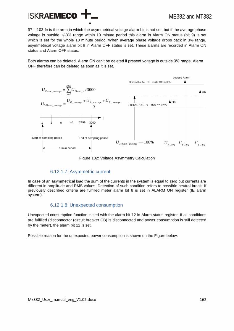
Mx382_User_manual_eng_V1.02.docx 162
ME382 and MT382
97 – 103 % is the area in which the asymmetrical voltage alarm bit is not set, but if the average phase
voltage is outside +/-3% range within 10 minute period this alarm in Alarm ON status (bit 9) is set
which is set for the whole 10 minute period. When average phase voltage drops back in 3% range,
asymmetrical voltage alarm bit 9 in Alarm OFF status is set. These alarms are recorded in Alarm ON
status and Alarm OFF status.
Both alarms can be deleted. Alarm ON can‟t be deleted if present voltage is outside 3% range. Alarm
OFF therefore can be deleted as soon as it is set.
Figure 102: Voltage Asymmetry Calculation
6.12.1.7. Asymmetric current
In case of an asymmetrical load the sum of the currents in the system is equal to zero but currents are different in amplitude and RMS values. Detection of such condition refers to possible neutral break. If previously described criteria are fulfilled meter alarm bit 8 is set in ALARM ON register (IE alarm system).
6.12.1.8. Unexpected consumption
Unexpected consumption function is tied with the alarm bit 12 in Alarm status register. If all conditions
are fulfilled (disconnector (circuit breaker CB) is disconnected and power consumption is still detected
by the meter), the alarm bit 12 is set.
Possible reason for the unexpected power consumption is shown on the Figure below:
t
2 n n+1 2999 30001
Start of sempling period End of sempling period
10min period
3000
0
__ 3000/n
nPhaseaveragePhase UU
3
___
_3
averageTaverageSaverageR
averagePhase
UUUU
%100_3 averagePhaseU
0-0:128.7.50 <- 1030 == 103%
0-0:128.7.51 <- 970 == 97%
avgRU _ avgSU _ avgTU _
OK
OK
couses Alarm

Mx382_User_manual_eng_V1.02.docx 163
ME382 and MT382
Figure 103: Unexpected consumption
6.12.1.9. Neutral missing detection
If neutral is missing the virtual neutral (N‟) is represent with T phase decreased toward zero, R and S
phase increased toward interfacial voltage (Figure below).
Figure 104: Intended neutral N-N'
Event "Neutral missing (89)" and system alarm "Neutral current 0" depend on the asymmetrical
voltage and the deviation of the average voltage from 230V. Neutral missing event occurs if the
following occurs:
asymmetric voltage occurred (voltage on single phase differs more than 3%),
average voltage on one phase (T) is decreased more than 30% from 230V (lower than 161V) and average voltage on any other phases (R or S) is increased more than 28% from 230V (upper than 294,4V).
6.12.1.10. Power failure
The following objects are registered in the meter:
Number of power failures in all three phases and per phase,
Number of long power failures in all three phases, in any phase and per phase,
Time of power failure in all three phases, in any phase and per phase,
Duration of last long power failures in all three phases, in any phase and per phase.
Duration of last long power failures objects show the duration of power failure if it is longer than time threshold set in Time threshold for long power failure.
0.4kV
CB
circuit breaker
MeterCustomerpublic power grid
grid
Customer
?

Mx382_User_manual_eng_V1.02.docx 164
ME382 and MT382
When power fail time reaches time threshold (in seconds) for Long Power Fail set in Time threshold for long power failure register than Long Power Fail is registered, else Power Fail is registered.
Figure 105: Power fail example
6.12.2 Reclosing counter
The re-closing counter represents number of the power outages shorter than re-closing time (3
minutes).
6.12.3 Watchdog counter
Watchdog counter represents number of watchdog events.
6.12.4 Cover opening counter
Cover opening counter represents number of meter and terminal cover openings.
6.12.5 Breaker opening counter
Breaker opening counter represents number of breaker (disconnector) disconnections.
6.13. Security
The coarse partitioning of the E-Meter security is devised into:
Physical Security,
Logical Security. The physical security is a traditional way of protecting e-meter from different tampering variants and
unauthorized access. With increase of smart meter numbers and the rise of AMI infrastructures, the
logical security was introduced in e-meters.

Mx382_User_manual_eng_V1.02.docx 165
ME382 and MT382
6.13.1 Physical security
Physical security is comprised of:
Seal protection,
Parameters switch.
6.13.1.1. Seal protection
There are two different set of seal protection. First set protects terminal cover while the second
protects meter cover. If seals are tampered with and either of the terminals is removed then the
corresponding events are recorded in the fraud event log. In case of terminal cover open, the
dedicated counter (Cover opening counter) is incremented as well. Following figure presents the
Logging capabilities of two tampering processes.
Figure 106: Meter and Terminal cover tamper logging
6.13.1.2. Parameter lock switch
Its primary function is to strengthen the meter access functionality. When put in locked position,
objects dedicated to factory parameterization are not accessible anymore. Furthermore certain
attributes of the dedicated objects are also inaccessible even though the proper key or security
method was used. The same mechanism applies for executing specific methods. Therefore Meter
reset (Master reset) can only be done when the parameter switch is in unlocked position.
6.13.1.3. Additional COSEM objects used
According to parameter switch position, bit 8 in the register is changed. If the parameter switch is in
locked position the bit will be set to 1 and if the switch is in disconnected position bit 8 will be set to 0.
When the switch is not locked the protection is disabled and when the switch is in locked position the
protection is enabled.
PlatformDispatcher TerminalCounter
Top Package::Adversary
E-Meter
{OR}
TerminalCoverOpenedTerminalCoverOpened
Counter++
FraudEventLog Alarms
TerminalCoverOpened TerminalCoverOpened
MeterCoverOpened
TerminalCover FraudAlarmON
MeterCoverOpened
MeterCover FraudAlarmON
MeterCoverOpened

Mx382_User_manual_eng_V1.02.docx 166
ME382 and MT382
6.13.2 Logical security
Logical security in e-meter is devided into two separate entities:
a) DLMS/COSEM Security, b) Additional Communication Security.
6.13.2.1. Overview of the cryptographic methods
The cryptographic components provide the security services of confidentiality, data integrity,
authentication, authorization and non-repudiation (a service that provides proof of the integrity and
origin of data). Two basic components on which cryptography relies upon are: an algorithm (or
cryptographic methodology) and a key. The algorithm is a mathematical function, and the key is a
parameter used in the transformation.
Basic types of approved cryptographic algorithms are:
cryptographic hash functions,
symmetric key algorithms,
asymmetric key algorithms.
Hash functions
Hash functions produce short representation of a longer message. A good hash function is a one-way
function. It is easy to compute the hash value from the particular input while backing up the process is
extremely difficult.
Hash functions take an input of arbitrary length and always output a fixed length value. Therefore the
alternative name for hash functions is message digest.
Message M1 is run through a hash function and a fixed message digest H1 is produced and
transferred along with the original message.
Symmetric key algorithms
Symmetric key algorithms (often called secret key algorithms) use a single key to both apply the
protection and to remove or check the protection. For example, the key used to encrypt data is also
used to decrypt the encrypted data. This key must be kept secret if the data is to retain its
cryptographic protection. Symmetric algorithms are used to provide:
confidentiality via encryption,
an assurance of authenticity or integrity via authentication,
mechanism to instantiate key establishment.
There are several approved algorithms for encryption and decryption of data chunks. Every algorithm
converts data to be protected (called plaintext) via security context (keys and other security context)
into ciphered text. The reverse procedure is also possible as shown in the figure below.

Mx382_User_manual_eng_V1.02.docx 167
ME382 and MT382
Figure 107: Encryption and decryption procedure
Currently for a forementioned procedures Advanced Encryption Standard (AES) is used. AES encrypts
and decrypts data in 128-bit blocks, using 128, 192 or 256 bit keys. All three key sizes are adequate.
Message authentication code works similar as ordinary hash function with one enhancement.
Additionally the secret material (secret key) is used in message digesting.
6.13.2.2. DLMS/COSEM security
Confidentiality and integrity are among the key requirements when open systems connect to public
media. With the increase of computational power, the requirements for strong cryptographic methods
also increase. DLMS/COSEM provides two main information security features for accessing and
transporting data:
data access security controls access to the data held by a DLMS/COSEM server,
data transport security allows the sending party to apply cryptographic protection to the xDLMS APDUs to ensure confidentiality and integrity. This requires ciphered APDUs.
The information is given partly at the beginning of the application association establishment with two
services:
applicationcontext,
authenticationcontext (the level of data access security), and partly by COSEM objects which define access to specific attributes.
Data access security
Data access security is managed by the Association LN object. Each COSEM server i.e. a logical
device may support Application Associations with various clients, each having a different role, and with
this, different access rights. Each Association object provides a list of objects visible in that particular
Application Association and also the access rights to objects‟ attributes and methods.
To be able to access data, the client must be properly authenticated. Upon Application Association
establishment, an authentication context is negotiated between the client and the server. This
specifies the required authentication of the peers, and, where needed, the security algorithm to verify
the authentication. Three data access security levels are provided:
Lowest level security (no security),
Low Level Security (LLS),
High Level Security (HLS).

Mx382_User_manual_eng_V1.02.docx 168
ME382 and MT382
For effective use of functionalities, meter must be properly configured.
E-meter supports three different clients with three different behaviors regarding authentication minimal
requirements, as shown in following table:
Client name Client L-SAP Minimal Security Requirements
Public 16 Lowest level security (no security)
Management 1 HLS (LLS as a backup)
Pre-established 102 No HLS nor LLS
Table 68: Set of supported clients
Authentication procedures
For every security level different authentication procedures are required. Authentication context and
specifically the COSEM Authentication Mechanism Name are presented in following table:
Authentication Mechanism Name ID
COSEM lowest level security mechanism name 0
COSEM low level security mechanism name 1
COSEM high level security mechanism name using MD5 3
COSEM high level security mechanism name using SHA-1 4
COSEM high level security mechanism name using GMAC 5
Table 69: Supported authentication mechanism names
The Lowest level security authentication context does not require any peer authentication. It allows
direct access to the data in the server, within the access rights available in the given Application
Association.
Authentication mechanism name is therefore not present in Application Association Request.
The purpose of Low Level Security (LLS) is to allow the authentication of clients by verifying the
password supplied. The server is not authenticated. The client has to supply the correct password
during the process of Application Associaition establishment. If the password is Accepted, the
Application Association is established and the client can access data within the access rights available
in the given Application Association. Otherwise, the Application Assoication is not established.
The purpose of High Level Security (HLS) is to allow mutual authentication of the client and the
server participating in an association.
This is a 4-pass process, involving the exchange of challenges during Application Association establishment, which is followed by exchanging the results of processing these challenges, using cryptographic methods. If the authentication takes place, the client can proceed to access data within the access rights available in the given Application Association, and it accepts data coming from the server. Otherwise, the Application Association is not established. When the number of unauthorized accesses (Authentication Failure Count) is bigger than predefined limit (Authentication Failure Count Limit), the meter logs a respective event and rejects every subsequent application request for a predefined amount of time (60 s). With this mechanism the risk of brute force attacks is mitigated. The last unauthorized access is timestamped (Authentication Failure Stamp).

Mx382_User_manual_eng_V1.02.docx 169
ME382 and MT382
Additional COSEM objects used
According to secure meter communication it is possible to access the e-meter only with Application
Association which is currently active in the e-meter. If user wants to access the e-meter with different
Application Association, new authentication mechanism name has to be written in the currently active
Application Association‟s "Authentication mechanism name" attribute ("Authentication mechanism id")
of the "Current association" object (0-0:40.0.0.255). The e-meter can now be accessed with the new
Application Association.
Setting mechanism ID to 0 means that access is allowed with every mechanism ID set in the
Application Association Request (password, SHA-1, MD5 or GMAC).
Data transport security
Data transport security relies on applying cryptographic protection to xDLMS APDUs. This is achieved
via several security mechanisms. The first mechanism is incorporated in application association
request with two application service elements:
The COSEM application context,
User information filled with Initiate Request primitive.
ASEs involved in security
The table below shows Different application context names and the relation between those names and
allowed types of xDLMS APDUs. Ciphered APDUs are allowed only in Application context name with
ciphering.
Application Context Name ID Unciphered APDUs Ciphered APDUs
Logical Name Referencing no ciphering 1 Yes No
Short Name Referencing no ciphering 2 Yes No
Logical Name Referencing with ciphering 3 Yes Yes
Short Name Referencing with ciphering 4 Yes Yes
Table 70: Application context names
Security context
The second mechanism is called the security context. The security context defines security attributes
relevant for the data transport security process of ciphering/deciphering. The elements are:
Security policy (determining what kind of protection to be used),
Security suite (specifying the security algorithm),
Security material relevant for the given security suite: • Encryption keys, • Authentication keys, • Initialization vectors (comprised of System title and current frame counter).
First two bullets are described in and held by the Security Setup COSEM object.
Security policy
The following security policies are specified and allowed:
Security is not imposed (0),
All messages to be authenticated (1),
All messages to be encrypted (2),
All messages to be authenticated and encrypted (3). Authenticated xDLMS APDUs may be used – within a ciphered application context – even when the
security policy in effect does not require that all messages must be authenticated.

Mx382_User_manual_eng_V1.02.docx 170
ME382 and MT382
Messages protected by higher security then what the security policy requires are always allowed
(provided that the application context negotiated allows them).
Security suite
A security suite determines the cryptographic algorithm used for message security. A security suite is
identified with a Security Suite ID. Security suite (0) utilizes the Galois/Counter Mode (GCM) with AES-
128. In this security suite, global keys are protected during transportation using the AES-128 key wrap
algorithm.
Security Suite Id Authentication algorithm Encryption algorithm Key transport method
0 AES-GCM-128 AES-GCM-128 Key wrapping using AES-128 key wrap
Table 71: Security suite
6.13.2.3. Additional communication security
There are several Iskraemeco‟s add-ons to DLMS/COSEM security. Firstly “DLMS channel options”
object for every channel on which COSEM server is present is introduced in order to cater different
market requirements.
DLMS channel options
With this object different settings can be introduced and technology shortcomings can be solved.
Option values are:
0 – All options are disabled,
1 – Ignore HDLC service class (need to be set for those e-meters that have external modemcommunicating with uC via HDLC),
2 – Security replay attack prevention (frame counter checking),
4 – Association Establishment with AARQ/AARE and Association Release follows diction inGreen Book.
DLMS association restrictions
With this object different associations can be prohibited on the same server. One can disable public,
management, pre-established or combination of those Application Associations by writing proper value
in this COSEM object.
Certification log
Certification log monitors specific objects and logs their old and new values. When the communication
log is full, the new attempts to change monitored objects are denied. More can be read at the
certification data log description.
6.13.2.4. Secure storage
Secure storage is a reserved space in FRAM which is cryptographically protected. In secure storage
e-meter stores all the necessary global encryption, authentication and master keys.
The cryptographic protection relies on AES-XTS Block Cipher Mode. The main characteristics of this
mode are:
Provide security for storage data at rest (not in transit),
Tweakable block cipher encryption mode (“non-malleable”),
Usage of two keys (in process of encryption/decryption) derived from cryptographic salt andhidden passwords.
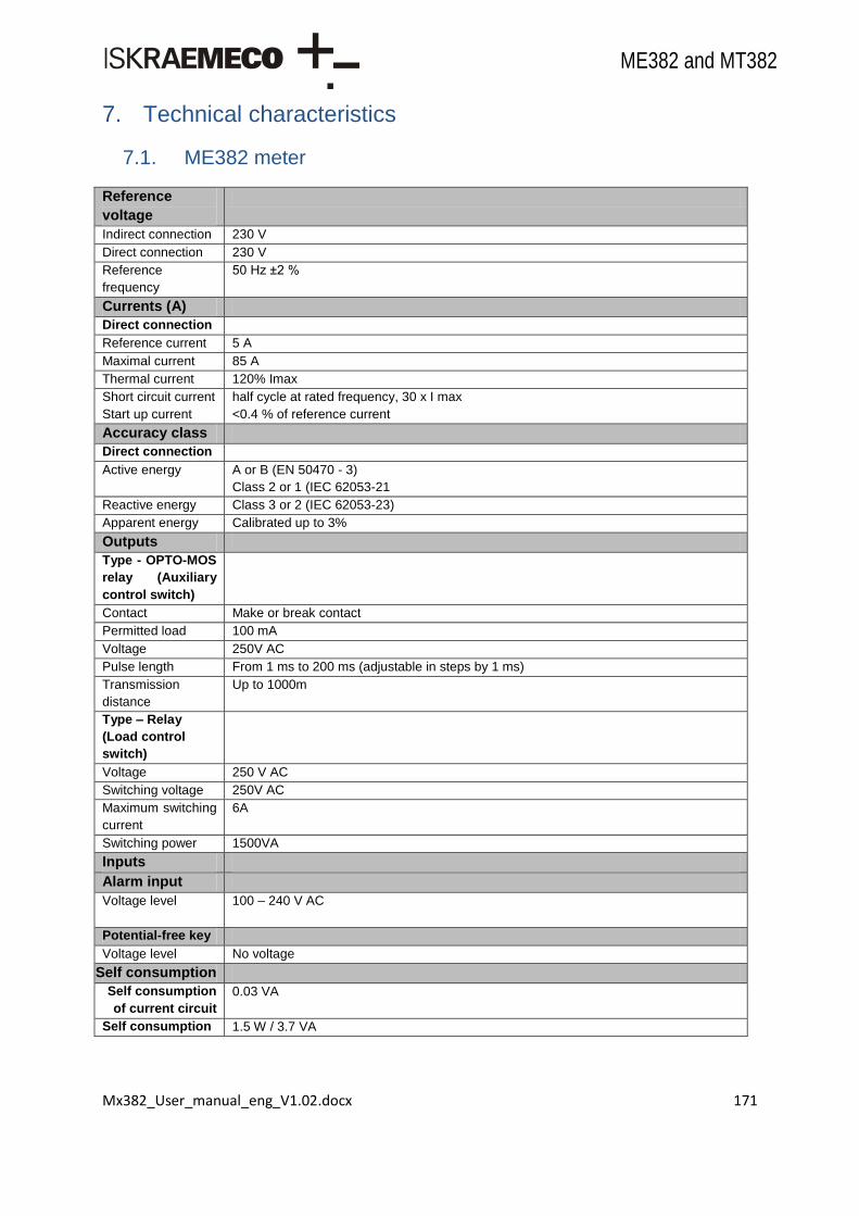
Mx382_User_manual_eng_V1.02.docx 171
ME382 and MT382
7. Technical characteristics
7.1. ME382 meter
Reference
voltage
Indirect connection 230 V
Direct connection 230 V
Reference
frequency
50 Hz ±2 %
Currents (A)
Direct connection
Reference current 5 A
Maximal current 85 A
Thermal current 120% Imax
Short circuit current
Start up current
half cycle at rated frequency, 30 x I max
<0.4 % of reference current
Accuracy class
Direct connection
Active energy A or B (EN 50470 - 3)
Class 2 or 1 (IEC 62053-21
Reactive energy Class 3 or 2 (IEC 62053-23)
Apparent energy Calibrated up to 3%
Outputs
Type - OPTO-MOS
relay (Auxiliary
control switch)
Contact Make or break contact
Permitted load 100 mA
Voltage 250V AC
Pulse length From 1 ms to 200 ms (adjustable in steps by 1 ms)
Transmission
distance
Up to 1000m
Type – Relay
(Load control
switch)
Voltage 250 V AC
Switching voltage 250V AC
Maximum switching
current
6A
Switching power 1500VA
Inputs
Alarm input
Voltage level 100 – 240 V AC
Potential-free key
Voltage level No voltage
Self consumption
Self consumption
of current circuit
0.03 VA
Self consumption 1.5 W / 3.7 VA

Mx382_User_manual_eng_V1.02.docx 172
ME382 and MT382
of voltage circuits
2.1 W / 4.8 VA (GSM communication established)
Communication
Port 0
Port 1
Infra red optical interface (IEC 62056-21 or IEC62056-46)
In-house device wired interface (IEC62056-21)
Port 2 M-Bus wired interface for multiutiliy (EN 13757)
Port 3 GSM/GPRS communication interface
LED output
Type LED – red
Number 2, function kWh/kvarh, kWh/kVA – programmable
Impulse frequency 2.5 kHz
Impulse length 30 ms
Constant Programmable
Real time clock
Accuracy Crystal: < 5 ppm = 3 min./year (at Top= +25C)
Back-up power
supply
Super-Cap: > 7 days, charging time 250 hours
Two Super-Cap: > 20 days, charging time 250 hours (optional)
EMC
Electrostatic
discharge
Contact 8kV, air 15 kV (IEC 61000-4-2)
VF magnetic field
(80MHz – 2 GHz)
20 V/m active and 40 V/m passive (IEC 61000-4-3)
Transient test
- Current and voltage circuit not under load
6 kV (IEC 61000-4-4)
- Auxiliary circuits > 40 V
2 kV
Surge test
- Current and voltage circuits
4 kV (IEC 61000-4-5)
- Auxiliary circuits > 40 V
1 kV
Insulation strength 4 kVrms, 50 Hz, 1 min
Impulse voltage
- Current and voltage circuits
12 kV voltage circuit, 6kV other
1.2/50 s (EN 50407-1)
- Auxiliary circuits
6 kV, 1.2/50 s (EN 50407-1)
Radio interference
suppression
Class B (EN 50022)
Immunity to
conducted
disturbances
20 V (EN 61000-4-6)
Glow wire test IEC 695-2-1
Spring hammer test IEC 60068-2-75
Temperature
ranges (IEC
62052-11)
Operation -40C ... +70C
LCD operation -25C ... +70C
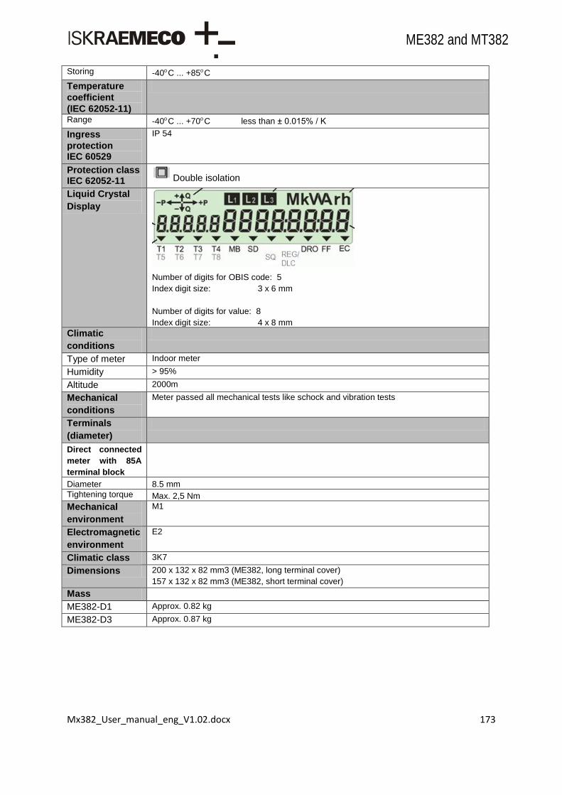
Mx382_User_manual_eng_V1.02.docx 173
ME382 and MT382
Storing -40C ... +85C
Temperature
coefficient
(IEC 62052-11)
Range -40C ... +70C less than ± 0.015% / K
Ingress
protection IEC 60529
IP 54
Protection class IEC 62052-11 Double isolation
Liquid Crystal
Display
Number of digits for OBIS code: 5
Index digit size: 3 x 6 mm
Number of digits for value: 8
Index digit size: 4 x 8 mm Climatic
conditions
Type of meter Indoor meter
Humidity > 95%
Altitude 2000m
Mechanical
conditions
Meter passed all mechanical tests like schock and vibration tests
Terminals
(diameter)
Direct connected
meter with 85A
terminal block
Diameter 8.5 mm
Tightening torque Max. 2,5 Nm
Mechanical
environment
M1
Electromagnetic
environment
E2
Climatic class 3K7
Dimensions 200 x 132 x 82 mm3 (ME382, long terminal cover)
157 x 132 x 82 mm3 (ME382, short terminal cover)
Mass
ME382-D1 Approx. 0.82 kg
ME382-D3 Approx. 0.87 kg
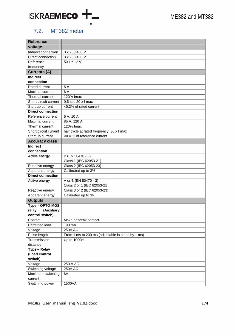
Mx382_User_manual_eng_V1.02.docx 174
ME382 and MT382
7.2. MT382 meter
Reference
voltage
Indirect connection 3 x 230/400 V
Direct connection 3 x 230/400 V
Reference
frequency
50 Hz ±2 %
Currents (A)
Indirect
connection
Rated current 5 A
Maximal current 6 A
Thermal current 120% Imax
Short circuit current 0,5 sec 20 x I max
Start up current <0.2% of rated current
Direct connection
Reference current 5 A, 10 A
Maximal current 85 A, 120 A
Thermal current 120% Imax
Short circuit current
Start up current
half cycle at rated frequency, 30 x I max
<0.4 % of reference current
Accuracy class
Indirect
connection
Active energy
B (EN 50470 - 3)
Class 1 (IEC 62053-21)
Reactive energy Class 2 (IEC 62053-23)
Apparent energy Calibrated up to 3%
Direct connection
Active energy A or B (EN 50470 - 3)
Class 2 or 1 (IEC 62053-21
Reactive energy Class 3 or 2 (IEC 62053-23)
Apparent energy Calibrated up to 3%
Outputs
Type - OPTO-MOS
relay (Auxiliary
control switch)
Contact Make or break contact
Permitted load 100 mA
Voltage 250V AC
Pulse length From 1 ms to 200 ms (adjustable in steps by 1 ms)
Transmission
distance
Up to 1000m
Type – Relay
(Load control
switch)
Voltage 250 V AC
Switching voltage 250V AC
Maximum switching
current
6A
Switching power 1500VA

Mx382_User_manual_eng_V1.02.docx 175
ME382 and MT382
Inputs
Alarm input
Voltage level 100 – 240 V AC
Potential-free key
Voltage level No voltage
Self consumption
Self consumption
of current circuit
Indirect connection
0.12 VA / phase
Direct connection
0.005 VA / phase
Self consumption
of voltage circuits
0.9 W / 2.3 VA
1.2 W / 2.9 VA (GSM communication established)
Communication
Port 0
Port 1
Infra red optical interface (IEC 62056-21 or IEC62056-46)
In-house device wired interface (IEC62056-21)
Port 2 M-Bus wired interface for multiutiliy (EN 13757)
Port 3 GSM/GPRS communication interface
LED output
Type LED – red
Number 2, function kWh/kvarh, kWh/kVA – programmable
Impulse frequency 2.5 kHz
Impulse length 30 ms
Constant Programmable
Real time clock
Accuracy Crystal: < 5 ppm = 3 min./year (at Top= +25C)
Back-up power
supply
Super-Cap: > 7 days, charging time 250 hours
Two Super-Cap: > 20 days, charging time 250 hours (optional)
EMC
Electrostatic
discharge
Contact 8kV, air 15 kV (IEC 61000-4-2)
VF magnetic field
(80MHz – 2 GHz)
20 V/m active and 40 V/m passive (IEC 61000-4-3)
Transient test
- Current and voltage circuit not under load
5 kV (IEC 61000-4-4)
- Auxiliary circuits > 40 V
2 kV
Surge test
- Current and voltage circuits
4 kV (IEC 61000-4-5)
- Auxiliary circuits > 40 V
1 kV
Insulation strength 4 kVrms, 50 Hz, 1 min
Impulse voltage
- Current and voltage circuits
12 kV voltage circuit, 6kV other
1.2/50 s (EN 50407-1)
- Auxiliary circuits
6 kV, 1.2/50 s (EN 50407-1)
Radio interference
suppression
Class B (EN 50022)

Mx382_User_manual_eng_V1.02.docx 176
ME382 and MT382
Immunity to
conducted
disturbances
20 V (EN 61000-4-6)
Immunity to
damped oscillatory
waves (Indirect
connection)
2.5 kV (common mode) (EN 61000-4-18 slow damped)
1 kV (differential mode)
Glow wire test IEC 695-2-1
Spring hammer test IEC 60068-2-75
Temperature
ranges (IEC
62052-11)
Operation -40C ... +70C
LCD operation -25C ... +70C
Storing -40C ... +85C
Temperature
coefficient
(IEC 62052-11)
Range -40C ... +70C less than ± 0.015% / K
Ingress
protection IEC 60529
IP 54
Protection class IEC 62052-11 Double insolation
Liquid Crystal
Display
Number of digits for OBIS code: 5
Index digit size: 3 x 6 mm
Number of digits for value: 8
Index digit size: 4 x 8 mm
Climatic
conditions
Type of meter Indoor meter
Humidity > 95%
Altitude 2000m
Mechanical
conditions
Meter passed all mechanical tests like schock and vibration tests
Terminals
(diameter)
Indirect
connected meter
Diameter 5 mm
Tightening torque Max. 1 Nm
Direct connected
meter with 85A
terminal block
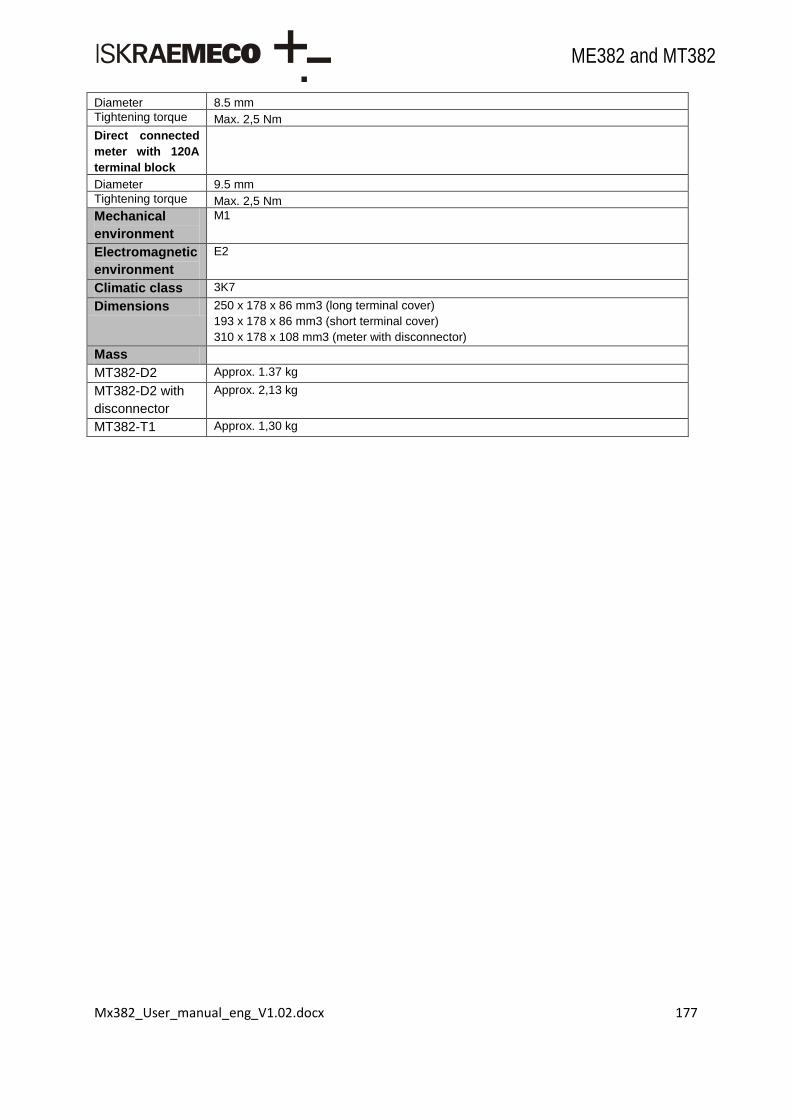
Mx382_User_manual_eng_V1.02.docx 177
ME382 and MT382
Diameter 8.5 mm
Tightening torque Max. 2,5 Nm
Direct connected
meter with 120A
terminal block
Diameter 9.5 mm
Tightening torque Max. 2,5 Nm
Mechanical
environment
M1
Electromagnetic
environment
E2
Climatic class 3K7
Dimensions 250 x 178 x 86 mm3 (long terminal cover)
193 x 178 x 86 mm3 (short terminal cover)
310 x 178 x 108 mm3 (meter with disconnector)
Mass
MT382-D2 Approx. 1.37 kg
MT382-D2 with
disconnector
Approx. 2,13 kg
MT382-T1 Approx. 1,30 kg

Mx382_User_manual_eng_V1.02.docx 178
ME382 and MT382
Annex 1: ME382 object list
Object OBIS code
Clock 0-0:1.0.0.255
Modem Configuration 0-0:2.0.0.255
Auto Dial 0-0:2.1.0.255
Auto Answer 0-0:2.2.0.255
Script Global Meter Reset 0-0:10.0.0.255
Script Table Endofbilling 0-0:10.0.1.255
Script Table Tariffication 0-0:10.0.100.255
Script Table Activate Testmode 0-0:10.0.101.255
Script Table Activate Normalmode 0-0:10.0.102.255
Script Table Load Management 0-0:10.0.103.255
Script Table Disconnect Control 0-0:10.0.106.255
Script Table Image Transfer 0-0:10.0.107.255
Script Table Push 0-0:10.0.108.255
Script Table Activate Display Testmode 0-0:10.1.101.255
Prepayment Activate Payment 0-0:10.1.251.255
Script Table Upgrade 0-0:10.1.253.255
Script Mbusclient Install 0-0:10.50.128.255
Script Mbusclient Remove 0-0:10.50.129.255
Special Days Table 0-0:11.0.0.255
Activity Calendar 0-0:13.0.0.255
Register Activation 0-0:14.0.1.255
Register Activation2 0-0:14.0.2.255
Single Action Schedule End Of Billing 0-0:15.0.0.255
Single Action Schedule Disconnect Control 0-0:15.0.1.255
Single Action Schedule Image Transfer 0-0:15.0.2.255
Single Action Schedule Read 0-0:15.1.0.255
Alarm1 Monitor 0-0:16.1.0.255
Alarm2 Monitor 0-0:16.1.1.255
Limiter 0-0:17.0.0.255
Limiter2 0-0:17.0.1.255
Iec Local Port Setup Ch0 0-0:20.0.0.255
Profile General Local Port Readout 0-0:21.0.0.255
Profile General Display Readout 0-0:21.0.1.255
Profile Alternate Display Readout 0-0:21.0.2.255
Iec Hdlc Setup Ch0 0-0:22.0.0.255
Mbus Master Port Setup Ch0 0-0:24.6.0.255
Tcp Udp Setup 0-0:25.0.0.255
Ipv4 Setup 0-0:25.1.0.255
Ppp Setup 0-0:25.3.0.255
Gprs Modem Setup 0-0:25.4.0.255
Push Setup On Wake Up 0-0:25.9.0.255
Association Ln 0-0:40.0.0.255
Sap Assignment 0-0:41.0.0.255
Device Logical Name 0-0:42.0.0.255
Security Setup 0-0:43.0.0.255
Frame Counter Rx 0 0-0:43.1.0.255

Mx382_User_manual_eng_V1.02.docx 179
ME382 and MT382
Frame Counter Rx 1 0-0:43.1.1.255
Image Transfer 0-0:44.0.0.255
Deviceid1 0-0:96.1.0.255
Deviceid2 0-0:96.1.1.255
Deviceid3 0-0:96.1.2.255
Deviceid4 0-0:96.1.3.255
Deviceid5 0-0:96.1.4.255
Deviceid6 0-0:96.1.5.255
Deviceid7 0-0:96.1.6.255
Deviceid8 0-0:96.1.7.255
Deviceid9 0-0:96.1.8.255
Config Program Change Counter 0-0:96.2.0.255
Config Program Change Stamp 0-0:96.2.1.255
Security Switches Status 0-0:96.2.4.255
Input Control Signals 0-0:96.3.1.255
Output Control Signals 0-0:96.3.2.255
Disconnect Control 0-0:96.3.10.255
Device Status 0-0:96.5.0.255
Battery Time Use Counter 0-0:96.6.0.255
Battery Estimated Remaining Time 0-0:96.6.6.255
Phase Total Failure Counter 0-0:96.7.0.255
Phase All Failure Long Counter 0-0:96.7.5.255
Phase Any Failure Long Counter 0-0:96.7.9.255
Phase All Failure Time 0-0:96.7.10.255
Phase Any Failure Time 0-0:96.7.14.255
Phase All Failure Duration 0-0:96.7.15.255
Phase Any Failure Duration 0-0:96.7.19.255
Long Power Failure Time Threshold 0-0:96.7.20.255
Phase Any Failure Counter 0-0:96.7.21.255
Profile Status0 0-0:96.10.1.255
Profile Status1 0-0:96.10.2.255
Profile Status2 0-0:96.10.3.255
Profile Status3 0-0:96.10.4.255
Serialprocess Status Ch0 0-0:96.10.128.255
Event Status1 0-0:96.11.0.255
Event Status2 0-0:96.11.1.255
Event Status3 0-0:96.11.2.255
Event Status4 0-0:96.11.3.255
Event Status5 0-0:96.11.4.255
Event Status7 0-0:96.11.6.255
Consumer Message Text 0-0:96.13.0.255
Consumer Message Code 0-0:96.13.1.255
Current Active Tariff 0-0:96.14.0.255
Cover Opening Counter 0-0:96.15.0.255
Breaker Opening Counter 0-0:96.15.1.255
Image Transfer Counter 0-0:96.63.10.255
Rom Checksum 0-0:96.96.0.255
Modified Secure Param Id 0-0:96.128.0.255
Modified Secure Param Old Value 0-0:96.128.1.255

Mx382_User_manual_eng_V1.02.docx 180
ME382 and MT382
Modified Secure Param New Value 0-0:96.128.2.255
Error1 0-0:97.97.0.255
Error2 0-0:97.97.1.255
Alarm Status 0-0:97.98.0.255
Alarm Status2 0-0:97.98.1.255
Alarm Filter 0-0:97.98.10.255
Alarm Filter2 0-0:97.98.11.255
Alarm Descriptor1 0-0:97.98.20.255
Alarm Descriptor2 0-0:97.98.21.255
Profile Billing1 0-0:98.1.0.255
Profile Billing2 0-0:98.2.0.255
Profile Eventlog 0-0:99.98.0.255
Profile Eventlog1 0-0:99.98.1.255
Profile Eventlog2 0-0:99.98.2.255
Profile Eventlog3 0-0:99.98.3.255
Profile Eventlog4 0-0:99.98.4.255
Profile Eventlog6 0-0:99.98.6.255
Rtc Mode 0-0:128.1.0.255
Rtc Calibration Value 0-0:128.1.1.255
Rtc Backup Type 0-0:128.1.2.255
Rtc Backup Duration 0-0:128.1.3.255
Meas Calibrate Status 0-0:128.5.0.255
Meas Calibration Constants0 0-0:128.5.1.255
Wdt Counter 0-0:128.6.0.255
Phase All Failure Short Counter 0-0:128.6.1.255
Pq L1 Voltage Level 1 0-0:128.7.11.255
Pq L1 Voltage Level 2 0-0:128.7.12.255
Pq L1 Voltage Level 3 0-0:128.7.13.255
Pq L1 Voltage Level 4 0-0:128.7.14.255
Pq L1 Voltage Level 5 0-0:128.7.15.255
Pq L1 Voltage Level 6 0-0:128.7.16.255
Pq L1 Voltage Level 7 0-0:128.7.17.255
Pq L1 Voltage Peak Current 0-0:128.8.10.255
Pq L1 Voltage Peak Previous 0-0:128.8.11.255
Pq L1 Voltage Min Current 0-0:128.8.12.255
Pq L1 Voltage Min Previous 0-0:128.8.13.255
Pq Voltage Min Max Period 0-0:128.8.50.255
Tariff Source 0-0:128.10.0.255
Tariff Mp Synchronisation 0-0:128.10.1.255
Gsm Csq 0-0:128.20.0.255
Gsm Status 0-0:128.20.1.255
Gsm Iccid 0-0:128.20.2.255
Gsm Program Version 0-0:128.20.3.255
Gsm Imei 0-0:128.20.4.255
Gsm Network Name 0-0:128.20.5.255
Gsm Wipsoft Program Version 0-0:128.20.6.255
Gsm Csq Limit1 0-0:128.20.11.255
Gsm Csq Limit2 0-0:128.20.12.255
No Connection Timeout 0-0:128.20.30.255

Mx382_User_manual_eng_V1.02.docx 181
ME382 and MT382
Load Control Mode 0-0:128.30.0.255
Load Control Power On Delay 0-0:128.30.2.255
Load Control Switch On Delay 0-0:128.30.3.255
Service Control Mode 0-0:128.30.10.255
Service Control Power On Delay 0-0:128.30.12.255
Service Control Switch On Delay 0-0:128.30.13.255
Service Control Functionality 0-0:128.30.14.255
Disconnect Control Type 0-0:128.30.20.255
Disconnect Control Manual Connect Period 0-0:128.30.24.255
Mem Partition0 0-0:128.40.0.255
Mem Partition1 0-0:128.40.1.255
Mem Partition2 0-0:128.40.2.255
Mem Partition3 0-0:128.40.3.255
Mem Partition4 0-0:128.40.4.255
Flashdev Spy Param 0-0:128.41.0.255
Flashdev Spy Values 0-0:128.41.1.255
Mbus Client Config 0-0:128.50.1.255
Prepayment Payment Mode 0-0:128.60.0.255
Prepayment Available Credit 0-0:128.60.1.255
Prepayment Emergency Credit 0-0:128.60.2.255
Prepayment Payment Status 0-0:128.60.3.255
Prepayment Total Purchase Register 0-0:128.60.4.255
Prepayment Emergency Credit Initial Limit 0-0:128.60.10.255
Prepayment Emergency Credit Limit 0-0:128.60.11.255
Prepayment Emergency Credit Threshold 0-0:128.60.12.255
Prepayment Active Auxiliary Charge 0-0:128.60.20.255
Prepayment Active Rate1 0-0:128.60.21.255
Prepayment Active Rate2 0-0:128.60.22.255
Prepayment Active Rate3 0-0:128.60.23.255
Prepayment Active Rate4 0-0:128.60.24.255
Prepayment Active Rate5 0-0:128.60.25.255
Prepayment Active Rate6 0-0:128.60.26.255
Prepayment Active Rate7 0-0:128.60.27.255
Prepayment Active Rate8 0-0:128.60.28.255
Prepayment Credit Transfer 0-0:128.60.30.255
Prepayment Eneregy Register Reference 0-0:128.60.31.255
Prepayment Accounting Register Reference 0-0:128.60.32.255
Prepayment Passive Auxiliary Charge 0-0:128.60.40.255
Prepayment Passive Rate1 0-0:128.60.41.255
Prepayment Passive Rate2 0-0:128.60.42.255
Prepayment Passive Rate3 0-0:128.60.43.255
Prepayment Passive Rate4 0-0:128.60.44.255
Prepayment Passive Rate5 0-0:128.60.45.255
Prepayment Passive Rate6 0-0:128.60.46.255
Prepayment Passive Rate7 0-0:128.60.47.255
Prepayment Passive Rate8 0-0:128.60.48.255
Registermonitor Current Exceeding Period 0-0:128.62.10.255
Dlms Options Ch0 0-0:128.70.0.255
Dlms Association Restrictions Ch0 0-0:128.70.1.255
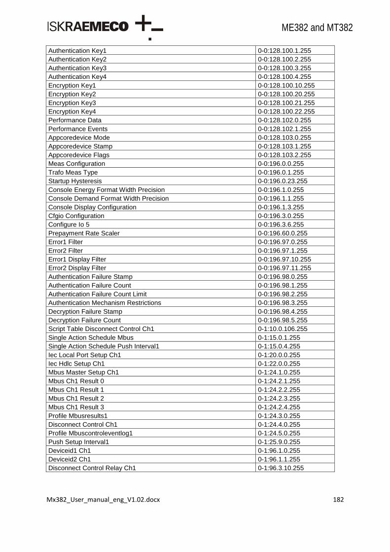
Mx382_User_manual_eng_V1.02.docx 182
ME382 and MT382
Authentication Key1 0-0:128.100.1.255
Authentication Key2 0-0:128.100.2.255
Authentication Key3 0-0:128.100.3.255
Authentication Key4 0-0:128.100.4.255
Encryption Key1 0-0:128.100.10.255
Encryption Key2 0-0:128.100.20.255
Encryption Key3 0-0:128.100.21.255
Encryption Key4 0-0:128.100.22.255
Performance Data 0-0:128.102.0.255
Performance Events 0-0:128.102.1.255
Appcoredevice Mode 0-0:128.103.0.255
Appcoredevice Stamp 0-0:128.103.1.255
Appcoredevice Flags 0-0:128.103.2.255
Meas Configuration 0-0:196.0.0.255
Trafo Meas Type 0-0:196.0.1.255
Startup Hysteresis 0-0:196.0.23.255
Console Energy Format Width Precision 0-0:196.1.0.255
Console Demand Format Width Precision 0-0:196.1.1.255
Console Display Configuration 0-0:196.1.3.255
Cfgio Configuration 0-0:196.3.0.255
Configure Io 5 0-0:196.3.6.255
Prepayment Rate Scaler 0-0:196.60.0.255
Error1 Filter 0-0:196.97.0.255
Error2 Filter 0-0:196.97.1.255
Error1 Display Filter 0-0:196.97.10.255
Error2 Display Filter 0-0:196.97.11.255
Authentication Failure Stamp 0-0:196.98.0.255
Authentication Failure Count 0-0:196.98.1.255
Authentication Failure Count Limit 0-0:196.98.2.255
Authentication Mechanism Restrictions 0-0:196.98.3.255
Decryption Failure Stamp 0-0:196.98.4.255
Decryption Failure Count 0-0:196.98.5.255
Script Table Disconnect Control Ch1 0-1:10.0.106.255
Single Action Schedule Mbus 0-1:15.0.1.255
Single Action Schedule Push Interval1 0-1:15.0.4.255
Iec Local Port Setup Ch1 0-1:20.0.0.255
Iec Hdlc Setup Ch1 0-1:22.0.0.255
Mbus Master Setup Ch1 0-1:24.1.0.255
Mbus Ch1 Result 0 0-1:24.2.1.255
Mbus Ch1 Result 1 0-1:24.2.2.255
Mbus Ch1 Result 2 0-1:24.2.3.255
Mbus Ch1 Result 3 0-1:24.2.4.255
Profile Mbusresults1 0-1:24.3.0.255
Disconnect Control Ch1 0-1:24.4.0.255
Profile Mbuscontroleventlog1 0-1:24.5.0.255
Push Setup Interval1 0-1:25.9.0.255
Deviceid1 Ch1 0-1:96.1.0.255
Deviceid2 Ch1 0-1:96.1.1.255
Disconnect Control Relay Ch1 0-1:96.3.10.255

Mx382_User_manual_eng_V1.02.docx 183
ME382 and MT382
Profile Mbusstatus1 0-1:96.10.3.255
Serialprocess Status Ch1 0-1:96.10.128.255
Event Status Mbuscontroleventlog1 0-1:96.11.4.255
Dlms Options Ch1 0-1:128.70.0.255
Dlms Association Restrictions Ch1 0-1:128.70.1.255
Single Action Schedule Push Interval2 0-2:15.0.4.255
Iec Local Port Setup Ch2 0-2:20.0.0.255
Iec Hdlc Setup Ch2 0-2:22.0.0.255
Mbus Master Setup Ch2 0-2:24.1.0.255
Mbus Ch2 Result 0 0-2:24.2.1.255
Mbus Ch2 Result 1 0-2:24.2.2.255
Mbus Ch2 Result 2 0-2:24.2.3.255
Mbus Ch2 Result 3 0-2:24.2.4.255
Profile Mbusresults2 0-2:24.3.0.255
Disconnect Control Ch2 0-2:24.4.0.255
Profile Mbuscontroleventlog2 0-2:24.5.0.255
Push Setup Interval2 0-2:25.9.0.255
Deviceid1 Ch2 0-2:96.1.0.255
Deviceid2 Ch2 0-2:96.1.1.255
Disconnect Control Relay Ch2 0-2:96.3.10.255
Profile Mbusstatus2 0-2:96.10.3.255
Serialprocess Status Ch2 0-2:96.10.128.255
Event Status Mbuscontroleventlog2 0-2:96.11.4.255
Dlms Options Ch2 0-2:128.70.0.255
Dlms Association Restrictions Ch2 0-2:128.70.1.255
Single Action Schedule Push Interval3 0-3:15.0.4.255
Mbus Master Setup Ch3 0-3:24.1.0.255
Mbus Ch3 Result 0 0-3:24.2.1.255
Mbus Ch3 Result 1 0-3:24.2.2.255
Mbus Ch3 Result 2 0-3:24.2.3.255
Mbus Ch3 Result 3 0-3:24.2.4.255
Profile Mbusresults3 0-3:24.3.0.255
Disconnect Control Ch3 0-3:24.4.0.255
Profile Mbuscontroleventlog3 0-3:24.5.0.255
Push Setup Interval3 0-3:25.9.0.255
Deviceid1 Ch3 0-3:96.1.0.255
Deviceid2 Ch3 0-3:96.1.1.255
Profile Mbusstatus3 0-3:96.10.3.255
Serialprocess Status Ch3 0-3:96.10.128.255
Event Status Mbuscontroleventlog3 0-3:96.11.4.255
Mbus Master Setup Ch4 0-4:24.1.0.255
Mbus Ch4 Result 0 0-4:24.2.1.255
Mbus Ch4 Result 1 0-4:24.2.2.255
Mbus Ch4 Result 2 0-4:24.2.3.255
Mbus Ch4 Result 3 0-4:24.2.4.255
Profile Mbusresults4 0-4:24.3.0.255
Disconnect Control Ch4 0-4:24.4.0.255
Profile Mbuscontroleventlog4 0-4:24.5.0.255
Push Setup On Alarm 0-4:25.9.0.255

Mx382_User_manual_eng_V1.02.docx 184
ME382 and MT382
Deviceid1 Ch4 0-4:96.1.0.255
Deviceid2 Ch4 0-4:96.1.1.255
Profile Mbusstatus4 0-4:96.10.3.255
Event Status Mbuscontroleventlog4 0-4:96.11.4.255
Push Setup On Power Down 0-5:25.9.0.255
Push Setup On Installation 0-7:25.9.0.255
Device Address1 1-0:0.0.0.255
Billing Period Counter 1-0:0.1.0.255
Image Core Identification 1-0:0.2.0.255
Image Core Signature 1-0:0.2.8.255
Metroled A Constant 1-0:0.3.0.255
Metroled Q Constant 1-0:0.3.1.255
Metroled S Constant 1-0:0.3.2.255
Outputpulse A Constant 1-0:0.3.3.255
Outputpulse Q Constant 1-0:0.3.4.255
Outputpulse S Constant 1-0:0.3.5.255
Traforatio Current Numerator 1-0:0.4.2.255
Traforatio Voltage Numerator 1-0:0.4.3.255
Traforatio Current Denominator 1-0:0.4.5.255
Traforatio Voltage Denominator 1-0:0.4.6.255
Voltage Nominal 1-0:0.6.0.255
Period 1-0:0.8.0.255
Measurement Period3 1-0:0.8.2.255
Local Time 1-0:0.9.1.255
Local Date 1-0:0.9.2.255
Time Set Limit 1-0:0.9.11.255
Active Demand Current Plus 1-0:1.4.0.255
Active Demand Last Plus 1-0:1.5.0.255
Maximum Demand Plus 1-0:1.6.0.255
Maximum Demand Plus T1 1-0:1.6.1.255
Maximum Demand Plus T2 1-0:1.6.2.255
Maximum Demand Plus T3 1-0:1.6.3.255
Maximum Demand Plus T4 1-0:1.6.4.255
Maximum Demand Plus T5 1-0:1.6.5.255
Maximum Demand Plus T6 1-0:1.6.6.255
Maximum Demand Plus T7 1-0:1.6.7.255
Maximum Demand Plus T8 1-0:1.6.8.255
Activepower Plus Instantaneous 1-0:1.7.0.255
Active Energy Plus 1-0:1.8.0.255
Active Energy Plus T1 1-0:1.8.1.255
Active Energy Plus T2 1-0:1.8.2.255
Active Energy Plus T3 1-0:1.8.3.255
Active Energy Plus T4 1-0:1.8.4.255
Active Energy Plus T5 1-0:1.8.5.255
Active Energy Plus T6 1-0:1.8.6.255
Active Energy Plus T7 1-0:1.8.7.255
Active Energy Plus T8 1-0:1.8.8.255
Active Demand Avg3 Plus 1-0:1.24.0.255
Active Demand Current Minus 1-0:2.4.0.255

Mx382_User_manual_eng_V1.02.docx 185
ME382 and MT382
Active Demand Last Minus 1-0:2.5.0.255
Maximum Demand Minus 1-0:2.6.0.255
Maximum Demand Minus T1 1-0:2.6.1.255
Maximum Demand Minus T2 1-0:2.6.2.255
Maximum Demand Minus T3 1-0:2.6.3.255
Maximum Demand Minus T4 1-0:2.6.4.255
Maximum Demand Minus T5 1-0:2.6.5.255
Maximum Demand Minus T6 1-0:2.6.6.255
Maximum Demand Minus T7 1-0:2.6.7.255
Maximum Demand Minus T8 1-0:2.6.8.255
Activepower Minus Instantaneous 1-0:2.7.0.255
Active Energy Minus 1-0:2.8.0.255
Active Energy Minus T1 1-0:2.8.1.255
Active Energy Minus T2 1-0:2.8.2.255
Active Energy Minus T3 1-0:2.8.3.255
Active Energy Minus T4 1-0:2.8.4.255
Active Energy Minus T5 1-0:2.8.5.255
Active Energy Minus T6 1-0:2.8.6.255
Active Energy Minus T7 1-0:2.8.7.255
Active Energy Minus T8 1-0:2.8.8.255
Reactive Demand Current Plus 1-0:3.4.0.255
Reactive Demand Last Plus 1-0:3.5.0.255
Reactive Maximum Demand Plus 1-0:3.6.0.255
Reactive Maximum Demand Plus T1 1-0:3.6.1.255
Reactive Maximum Demand Plus T2 1-0:3.6.2.255
Reactive Maximum Demand Plus T3 1-0:3.6.3.255
Reactive Maximum Demand Plus T4 1-0:3.6.4.255
Reactive Maximum Demand Plus T5 1-0:3.6.5.255
Reactive Maximum Demand Plus T6 1-0:3.6.6.255
Reactive Maximum Demand Plus T7 1-0:3.6.7.255
Reactive Maximum Demand Plus T8 1-0:3.6.8.255
Reactive Power Plus Instantaneous 1-0:3.7.0.255
Reactive Energy Plus 1-0:3.8.0.255
Reactive Energy Plus T1 1-0:3.8.1.255
Reactive Energy Plus T2 1-0:3.8.2.255
Reactive Energy Plus T3 1-0:3.8.3.255
Reactive Energy Plus T4 1-0:3.8.4.255
Reactive Energy Plus T5 1-0:3.8.5.255
Reactive Energy Plus T6 1-0:3.8.6.255
Reactive Energy Plus T7 1-0:3.8.7.255
Reactive Energy Plus T8 1-0:3.8.8.255
Reactive Demand Current Minus 1-0:4.4.0.255
Reactive Demand Last Minus 1-0:4.5.0.255
Reactive Maximum Demand Minus 1-0:4.6.0.255
Reactive Maximum Demand Minus T1 1-0:4.6.1.255
Reactive Maximum Demand Minus T2 1-0:4.6.2.255
Reactive Maximum Demand Minus T3 1-0:4.6.3.255
Reactive Maximum Demand Minus T4 1-0:4.6.4.255
Reactive Maximum Demand Minus T5 1-0:4.6.5.255

Mx382_User_manual_eng_V1.02.docx 186
ME382 and MT382
Reactive Maximum Demand Minus T6 1-0:4.6.6.255
Reactive Maximum Demand Minus T7 1-0:4.6.7.255
Reactive Maximum Demand Minus T8 1-0:4.6.8.255
Reactive Power Minus Instantaneous 1-0:4.7.0.255
Reactive Energy Minus 1-0:4.8.0.255
Reactive Energy Minus T1 1-0:4.8.1.255
Reactive Energy Minus T2 1-0:4.8.2.255
Reactive Energy Minus T3 1-0:4.8.3.255
Reactive Energy Minus T4 1-0:4.8.4.255
Reactive Energy Minus T5 1-0:4.8.5.255
Reactive Energy Minus T6 1-0:4.8.6.255
Reactive Energy Minus T7 1-0:4.8.7.255
Reactive Energy Minus T8 1-0:4.8.8.255
Reactive Energy Q1 1-0:5.8.0.255
Reactive Energy Q1 T1 1-0:5.8.1.255
Reactive Energy Q1 T2 1-0:5.8.2.255
Reactive Energy Q1 T3 1-0:5.8.3.255
Reactive Energy Q1 T4 1-0:5.8.4.255
Reactive Energy Q1 T5 1-0:5.8.5.255
Reactive Energy Q1 T6 1-0:5.8.6.255
Reactive Energy Q1 T7 1-0:5.8.7.255
Reactive Energy Q1 T8 1-0:5.8.8.255
Reactive Energy Q2 1-0:6.8.0.255
Reactive Energy Q2 T1 1-0:6.8.1.255
Reactive Energy Q2 T2 1-0:6.8.2.255
Reactive Energy Q2 T3 1-0:6.8.3.255
Reactive Energy Q2 T4 1-0:6.8.4.255
Reactive Energy Q2 T5 1-0:6.8.5.255
Reactive Energy Q2 T6 1-0:6.8.6.255
Reactive Energy Q2 T7 1-0:6.8.7.255
Reactive Energy Q2 T8 1-0:6.8.8.255
Reactive Energy Q3 1-0:7.8.0.255
Reactive Energy Q3 T1 1-0:7.8.1.255
Reactive Energy Q3 T2 1-0:7.8.2.255
Reactive Energy Q3 T3 1-0:7.8.3.255
Reactive Energy Q3 T4 1-0:7.8.4.255
Reactive Energy Q3 T5 1-0:7.8.5.255
Reactive Energy Q3 T6 1-0:7.8.6.255
Reactive Energy Q3 T7 1-0:7.8.7.255
Reactive Energy Q3 T8 1-0:7.8.8.255
Reactive Energy Q4 1-0:8.8.0.255
Reactive Energy Q4 T1 1-0:8.8.1.255
Reactive Energy Q4 T2 1-0:8.8.2.255
Reactive Energy Q4 T3 1-0:8.8.3.255
Reactive Energy Q4 T4 1-0:8.8.4.255
Reactive Energy Q4 T5 1-0:8.8.5.255
Reactive Energy Q4 T6 1-0:8.8.6.255
Reactive Energy Q4 T7 1-0:8.8.7.255
Reactive Energy Q4 T8 1-0:8.8.8.255

Mx382_User_manual_eng_V1.02.docx 187
ME382 and MT382
Apparent Demand Current Plus 1-0:9.4.0.255
Apparent Demand Last Plus 1-0:9.5.0.255
Apparent Maximum Demand Plus 1-0:9.6.0.255
Apparent Maximum Demand Plus T1 1-0:9.6.1.255
Apparent Maximum Demand Plus T2 1-0:9.6.2.255
Apparent Maximum Demand Plus T3 1-0:9.6.3.255
Apparent Maximum Demand Plus T4 1-0:9.6.4.255
Apparent Maximum Demand Plus T5 1-0:9.6.5.255
Apparent Maximum Demand Plus T6 1-0:9.6.6.255
Apparent Maximum Demand Plus T7 1-0:9.6.7.255
Apparent Maximum Demand Plus T8 1-0:9.6.8.255
Apparent Power Plus Instantaneous 1-0:9.7.0.255
Apparent Energy Plus 1-0:9.8.0.255
Apparent Energy Plus T1 1-0:9.8.1.255
Apparent Energy Plus T2 1-0:9.8.2.255
Apparent Energy Plus T3 1-0:9.8.3.255
Apparent Energy Plus T4 1-0:9.8.4.255
Apparent Energy Plus T5 1-0:9.8.5.255
Apparent Energy Plus T6 1-0:9.8.6.255
Apparent Energy Plus T7 1-0:9.8.7.255
Apparent Energy Plus T8 1-0:9.8.8.255
Apparent Demand Current Minus 1-0:10.4.0.255
Apparent Demand Last Minus 1-0:10.5.0.255
Apparent Maximum Demand Minus 1-0:10.6.0.255
Apparent Maximum Demand Minus T1 1-0:10.6.1.255
Apparent Maximum Demand Minus T2 1-0:10.6.2.255
Apparent Maximum Demand Minus T3 1-0:10.6.3.255
Apparent Maximum Demand Minus T4 1-0:10.6.4.255
Apparent Maximum Demand Minus T5 1-0:10.6.5.255
Apparent Maximum Demand Minus T6 1-0:10.6.6.255
Apparent Maximum Demand Minus T7 1-0:10.6.7.255
Apparent Maximum Demand Minus T8 1-0:10.6.8.255
Apparent Power Minus Instantaneous 1-0:10.7.0.255
Apparent Energy Minus 1-0:10.8.0.255
Apparent Energy Minus T1 1-0:10.8.1.255
Apparent Energy Minus T2 1-0:10.8.2.255
Apparent Energy Minus T3 1-0:10.8.3.255
Apparent Energy Minus T4 1-0:10.8.4.255
Apparent Energy Minus T5 1-0:10.8.5.255
Apparent Energy Minus T6 1-0:10.8.6.255
Apparent Energy Minus T7 1-0:10.8.7.255
Apparent Energy Minus T8 1-0:10.8.8.255
Voltage Underlimit Threshold 1-0:12.31.0.255
Voltage Underlimit Time Integral 1-0:12.31.129.255
Voltage Underlimit Counter 1-0:12.32.0.255
Voltage Underlimit Duration 1-0:12.33.0.255
Voltage Underlimit Magnitude 1-0:12.34.0.255
Voltage Overlimit Threshold 1-0:12.35.0.255
Voltage Overlimit Time Integral 1-0:12.35.129.255

Mx382_User_manual_eng_V1.02.docx 188
ME382 and MT382
Voltage Overlimit Counter 1-0:12.36.0.255
Voltage Overlimit Duration 1-0:12.37.0.255
Voltage Overlimit Magnitude 1-0:12.38.0.255
Voltage Cut Underlimit Magnitude 1-0:12.39.0.255
Voltage Underlimit Time Threshold 1-0:12.43.0.255
Voltage Overlimit Time Threshold 1-0:12.44.0.255
Voltage Cut Time Threshold 1-0:12.45.0.255
Power Factor Positive Minimum Sum 1-0:13.3.0.255
Power Factor Positive Last Average Sum 1-0:13.5.0.255
Power Factor Positive Sum 1-0:13.7.0.255
Net Frequency Instantaneous 1-0:14.7.0.255
Active Demand Current Absolute 1-0:15.4.0.255
Active Demand Last Absolute 1-0:15.5.0.255
Active Maximum Demand Absolute 1-0:15.6.0.255
Active Maximum Demand Absolute T1 1-0:15.6.1.255
Active Maximum Demand Absolute T2 1-0:15.6.2.255
Active Maximum Demand Absolute T3 1-0:15.6.3.255
Active Maximum Demand Absolute T4 1-0:15.6.4.255
Active Maximum Demand Absolute T5 1-0:15.6.5.255
Active Maximum Demand Absolute T6 1-0:15.6.6.255
Active Maximum Demand Absolute T7 1-0:15.6.7.255
Active Maximum Demand Absolute T8 1-0:15.6.8.255
Activepower Absolute Instantaneous 1-0:15.7.0.255
Energy Absolute 1-0:15.8.0.255
Energy Absolute T1 1-0:15.8.1.255
Energy Absolute T2 1-0:15.8.2.255
Energy Absolute T3 1-0:15.8.3.255
Energy Absolute T4 1-0:15.8.4.255
Energy Absolute T5 1-0:15.8.5.255
Energy Absolute T6 1-0:15.8.6.255
Energy Absolute T7 1-0:15.8.7.255
Energy Absolute T8 1-0:15.8.8.255
Active Demand Avg3 Absolute 1-0:15.24.0.255
Energy Active Net 1-0:16.8.0.255
Active Demand Avg3 Net 1-0:16.24.0.255
Fuse Supervision Monitor L1 1-0:31.4.0.255
Fuse Supervision Monitor L1 1-0:31.4.0.255
Current Instantaneous L1 1-0:31.7.0.255
Voltage Instantaneous L1 1-0:32.7.0.255
Pq Voltage Average L1 1-0:32.24.0.255
Voltage Underlimit Counter L1 1-0:32.32.0.255
Voltage Underlimit Duration L1 1-0:32.33.0.255
Voltage Underlimit Magnitude L1 1-0:32.34.0.255
Voltage Overlimit Counter L1 1-0:32.36.0.255
Voltage Overlimit Duration L1 1-0:32.37.0.255
Voltage Overlimit Magnitude L1 1-0:32.38.0.255
Power Factor Positive L1 1-0:33.7.0.255
Current Instantaneous Sum 1-0:90.7.0.255
System Status Register 1-0:96.5.1.255

Mx382_User_manual_eng_V1.02.docx 189
ME382 and MT382
Power Failure Alarm Filtering Limit 1-0:96.239.0.255
Event Status1 1-0:96.241.0.255
Alarm On Status 1-0:96.242.0.255
Alarm On Status2 1-0:96.242.10.255
Alarm Off Status 1-0:96.243.0.255
Alarm Off Status2 1-0:96.243.10.255
Event System 1-0:96.245.0.255
Alarm System 1-0:96.246.0.255
Profile Period1 1-0:99.1.0.255
Profile Period2 1-0:99.2.0.255
Profile Powerfaillog 1-0:99.97.0.255
Profile Technical Log 1-0:99.99.0.255
Image Module Identification 1-1:0.2.0.255
Image Module Signature 1-1:0.2.8.255

Mx382_User_manual_eng_V1.02.docx 190
ME382 and MT382
Annex 2: MT382 object list
Object OBIS code
Clock 0-0:1.0.0.255
Modem Configuration 0-0:2.0.0.255
Auto Dial 0-0:2.1.0.255
Auto Answer 0-0:2.2.0.255
Script Global Meter Reset 0-0:10.0.0.255
Script Table Endofbilling 0-0:10.0.1.255
Script Table Tariffication 0-0:10.0.100.255
Script Table Activate Testmode 0-0:10.0.101.255
Script Table Activate Normalmode 0-0:10.0.102.255
Script Table Load Management 0-0:10.0.103.255
Script Table Disconnect Control 0-0:10.0.106.255
Script Table Image Transfer 0-0:10.0.107.255
Script Table Push 0-0:10.0.108.255
Script Table Activate Display Testmode 0-0:10.1.101.255
Prepayment Activate Payment 0-0:10.1.251.255
Script Table Upgrade 0-0:10.1.253.255
Script Mbusclient Install 0-0:10.50.128.255
Script Mbusclient Remove 0-0:10.50.129.255
Special Days Table 0-0:11.0.0.255
Activity Calendar 0-0:13.0.0.255
Register Activation 0-0:14.0.1.255
Register Activation2 0-0:14.0.2.255
Single Action Schedule End Of Billing 0-0:15.0.0.255
Single Action Schedule Disconnect Control 0-0:15.0.1.255
Single Action Schedule Image Transfer 0-0:15.0.2.255
Single Action Schedule Read 0-0:15.1.0.255
Alarm1 Monitor 0-0:16.1.0.255
Alarm2 Monitor 0-0:16.1.1.255
Limiter 0-0:17.0.0.255
Limiter2 0-0:17.0.1.255
Iec Local Port Setup Ch0 0-0:20.0.0.255
Profile General Local Port Readout 0-0:21.0.0.255
Profile General Display Readout 0-0:21.0.1.255
Profile Alternate Display Readout 0-0:21.0.2.255
Iec Hdlc Setup Ch0 0-0:22.0.0.255
Mbus Master Port Setup Ch0 0-0:24.6.0.255
Tcp Udp Setup 0-0:25.0.0.255
Ipv4 Setup 0-0:25.1.0.255
Ppp Setup 0-0:25.3.0.255
Gprs Modem Setup 0-0:25.4.0.255
Push Setup On Wake Up 0-0:25.9.0.255
Association Ln 0-0:40.0.0.255
Sap Assignment 0-0:41.0.0.255
Device Logical Name 0-0:42.0.0.255
Security Setup 0-0:43.0.0.255
Frame Counter Rx 0 0-0:43.1.0.255

Mx382_User_manual_eng_V1.02.docx 191
ME382 and MT382
Frame Counter Rx 1 0-0:43.1.1.255
Image Transfer 0-0:44.0.0.255
Deviceid1 0-0:96.1.0.255
Deviceid2 0-0:96.1.1.255
Deviceid3 0-0:96.1.2.255
Deviceid4 0-0:96.1.3.255
Deviceid5 0-0:96.1.4.255
Deviceid6 0-0:96.1.5.255
Deviceid7 0-0:96.1.6.255
Deviceid8 0-0:96.1.7.255
Deviceid9 0-0:96.1.8.255
Config Program Change Counter 0-0:96.2.0.255
Config Program Change Stamp 0-0:96.2.1.255
Security Switches Status 0-0:96.2.4.255
Input Control Signals 0-0:96.3.1.255
Output Control Signals 0-0:96.3.2.255
Disconnect Control 0-0:96.3.10.255
Device Status 0-0:96.5.0.255
Battery Time Use Counter 0-0:96.6.0.255
Battery Estimated Remaining Time 0-0:96.6.6.255
Phase Total Failure Counter 0-0:96.7.0.255
Phase L1 Failure Counter 0-0:96.7.1.255
Phase L2 Failure Counter 0-0:96.7.2.255
Phase L3 Failure Counter 0-0:96.7.3.255
Phase All Failure Long Counter 0-0:96.7.5.255
Phase L1 Failure Long Counter 0-0:96.7.6.255
Phase L2 Failure Long Counter 0-0:96.7.7.255
Phase L3 Failure Long Counter 0-0:96.7.8.255
Phase Any Failure Long Counter 0-0:96.7.9.255
Phase All Failure Time 0-0:96.7.10.255
Phase L1 Failure Time 0-0:96.7.11.255
Phase L2 Failure Time 0-0:96.7.12.255
Phase L3 Failure Time 0-0:96.7.13.255
Phase Any Failure Time 0-0:96.7.14.255
Phase All Failure Duration 0-0:96.7.15.255
Phase L1 Failure Duration 0-0:96.7.16.255
Phase L2 Failure Duration 0-0:96.7.17.255
Phase L3 Failure Duration 0-0:96.7.18.255
Phase Any Failure Duration 0-0:96.7.19.255
Long Power Failure Time Threshold 0-0:96.7.20.255
Phase Any Failure Counter 0-0:96.7.21.255
Profile Status0 0-0:96.10.1.255
Profile Status1 0-0:96.10.2.255
Profile Status2 0-0:96.10.3.255
Profile Status3 0-0:96.10.4.255
Serialprocess Status Ch0 0-0:96.10.128.255
Event Status1 0-0:96.11.0.255
Event Status2 0-0:96.11.1.255
Event Status3 0-0:96.11.2.255

Mx382_User_manual_eng_V1.02.docx 192
ME382 and MT382
Event Status4 0-0:96.11.3.255
Event Status5 0-0:96.11.4.255
Event Status7 0-0:96.11.6.255
Consumer Message Text 0-0:96.13.0.255
Consumer Message Code 0-0:96.13.1.255
Current Active Tariff 0-0:96.14.0.255
Cover Opening Counter 0-0:96.15.0.255
Breaker Opening Counter 0-0:96.15.1.255
Image Transfer Counter 0-0:96.63.10.255
Rom Checksum 0-0:96.96.0.255
Modified Secure Param Id 0-0:96.128.0.255
Modified Secure Param Old Value 0-0:96.128.1.255
Modified Secure Param New Value 0-0:96.128.2.255
Error1 0-0:97.97.0.255
Error2 0-0:97.97.1.255
Alarm Status 0-0:97.98.0.255
Alarm Status2 0-0:97.98.1.255
Alarm Filter 0-0:97.98.10.255
Alarm Filter2 0-0:97.98.11.255
Alarm Descriptor1 0-0:97.98.20.255
Alarm Descriptor2 0-0:97.98.21.255
Profile Billing1 0-0:98.1.0.255
Profile Billing2 0-0:98.2.0.255
Profile Eventlog 0-0:99.98.0.255
Profile Eventlog1 0-0:99.98.1.255
Profile Eventlog2 0-0:99.98.2.255
Profile Eventlog3 0-0:99.98.3.255
Profile Eventlog4 0-0:99.98.4.255
Profile Eventlog6 0-0:99.98.6.255
Rtc Mode 0-0:128.1.0.255
Rtc Calibration Value 0-0:128.1.1.255
Rtc Backup Type 0-0:128.1.2.255
Rtc Backup Duration 0-0:128.1.3.255
Meas Calibrate Status 0-0:128.5.0.255
Meas Calibration Constants0 0-0:128.5.1.255
Wdt Counter 0-0:128.6.0.255
Phase All Failure Short Counter 0-0:128.6.1.255
Pq L1 Voltage Level 1 0-0:128.7.11.255
Pq L1 Voltage Level 2 0-0:128.7.12.255
Pq L1 Voltage Level 3 0-0:128.7.13.255
Pq L1 Voltage Level 4 0-0:128.7.14.255
Pq L1 Voltage Level 5 0-0:128.7.15.255
Pq L1 Voltage Level 6 0-0:128.7.16.255
Pq L1 Voltage Level 7 0-0:128.7.17.255
Pq L2 Voltage Level 1 0-0:128.7.21.255
Pq L2 Voltage Level 2 0-0:128.7.22.255
Pq L2 Voltage Level 3 0-0:128.7.23.255
Pq L2 Voltage Level 4 0-0:128.7.24.255
Pq L2 Voltage Level 5 0-0:128.7.25.255
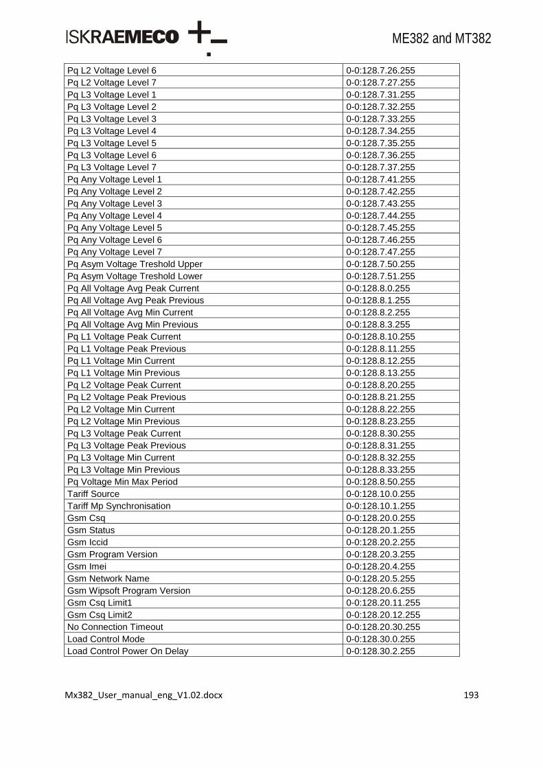
Mx382_User_manual_eng_V1.02.docx 193
ME382 and MT382
Pq L2 Voltage Level 6 0-0:128.7.26.255
Pq L2 Voltage Level 7 0-0:128.7.27.255
Pq L3 Voltage Level 1 0-0:128.7.31.255
Pq L3 Voltage Level 2 0-0:128.7.32.255
Pq L3 Voltage Level 3 0-0:128.7.33.255
Pq L3 Voltage Level 4 0-0:128.7.34.255
Pq L3 Voltage Level 5 0-0:128.7.35.255
Pq L3 Voltage Level 6 0-0:128.7.36.255
Pq L3 Voltage Level 7 0-0:128.7.37.255
Pq Any Voltage Level 1 0-0:128.7.41.255
Pq Any Voltage Level 2 0-0:128.7.42.255
Pq Any Voltage Level 3 0-0:128.7.43.255
Pq Any Voltage Level 4 0-0:128.7.44.255
Pq Any Voltage Level 5 0-0:128.7.45.255
Pq Any Voltage Level 6 0-0:128.7.46.255
Pq Any Voltage Level 7 0-0:128.7.47.255
Pq Asym Voltage Treshold Upper 0-0:128.7.50.255
Pq Asym Voltage Treshold Lower 0-0:128.7.51.255
Pq All Voltage Avg Peak Current 0-0:128.8.0.255
Pq All Voltage Avg Peak Previous 0-0:128.8.1.255
Pq All Voltage Avg Min Current 0-0:128.8.2.255
Pq All Voltage Avg Min Previous 0-0:128.8.3.255
Pq L1 Voltage Peak Current 0-0:128.8.10.255
Pq L1 Voltage Peak Previous 0-0:128.8.11.255
Pq L1 Voltage Min Current 0-0:128.8.12.255
Pq L1 Voltage Min Previous 0-0:128.8.13.255
Pq L2 Voltage Peak Current 0-0:128.8.20.255
Pq L2 Voltage Peak Previous 0-0:128.8.21.255
Pq L2 Voltage Min Current 0-0:128.8.22.255
Pq L2 Voltage Min Previous 0-0:128.8.23.255
Pq L3 Voltage Peak Current 0-0:128.8.30.255
Pq L3 Voltage Peak Previous 0-0:128.8.31.255
Pq L3 Voltage Min Current 0-0:128.8.32.255
Pq L3 Voltage Min Previous 0-0:128.8.33.255
Pq Voltage Min Max Period 0-0:128.8.50.255
Tariff Source 0-0:128.10.0.255
Tariff Mp Synchronisation 0-0:128.10.1.255
Gsm Csq 0-0:128.20.0.255
Gsm Status 0-0:128.20.1.255
Gsm Iccid 0-0:128.20.2.255
Gsm Program Version 0-0:128.20.3.255
Gsm Imei 0-0:128.20.4.255
Gsm Network Name 0-0:128.20.5.255
Gsm Wipsoft Program Version 0-0:128.20.6.255
Gsm Csq Limit1 0-0:128.20.11.255
Gsm Csq Limit2 0-0:128.20.12.255
No Connection Timeout 0-0:128.20.30.255
Load Control Mode 0-0:128.30.0.255
Load Control Power On Delay 0-0:128.30.2.255

Mx382_User_manual_eng_V1.02.docx 194
ME382 and MT382
Load Control Switch On Delay 0-0:128.30.3.255
Service Control Mode 0-0:128.30.10.255
Service Control Power On Delay 0-0:128.30.12.255
Service Control Switch On Delay 0-0:128.30.13.255
Service Control Functionality 0-0:128.30.14.255
Disconnect Control Type 0-0:128.30.20.255
Disconnect Control Manual Connect Period 0-0:128.30.24.255
Mem Partition0 0-0:128.40.0.255
Mem Partition1 0-0:128.40.1.255
Mem Partition2 0-0:128.40.2.255
Mem Partition3 0-0:128.40.3.255
Mem Partition4 0-0:128.40.4.255
Flashdev Spy Param 0-0:128.41.0.255
Flashdev Spy Values 0-0:128.41.1.255
Mbus Client Config 0-0:128.50.1.255
Prepayment Payment Mode 0-0:128.60.0.255
Prepayment Available Credit 0-0:128.60.1.255
Prepayment Emergency Credit 0-0:128.60.2.255
Prepayment Payment Status 0-0:128.60.3.255
Prepayment Total Purchase Register 0-0:128.60.4.255
Prepayment Emergency Credit Initial Limit 0-0:128.60.10.255
Prepayment Emergency Credit Limit 0-0:128.60.11.255
Prepayment Emergency Credit Threshold 0-0:128.60.12.255
Prepayment Active Auxiliary Charge 0-0:128.60.20.255
Prepayment Active Rate1 0-0:128.60.21.255
Prepayment Active Rate2 0-0:128.60.22.255
Prepayment Active Rate3 0-0:128.60.23.255
Prepayment Active Rate4 0-0:128.60.24.255
Prepayment Active Rate5 0-0:128.60.25.255
Prepayment Active Rate6 0-0:128.60.26.255
Prepayment Active Rate7 0-0:128.60.27.255
Prepayment Active Rate8 0-0:128.60.28.255
Prepayment Credit Transfer 0-0:128.60.30.255
Prepayment Eneregy Register Reference 0-0:128.60.31.255
Prepayment Accounting Register Reference 0-0:128.60.32.255
Prepayment Passive Auxiliary Charge 0-0:128.60.40.255
Prepayment Passive Rate1 0-0:128.60.41.255
Prepayment Passive Rate2 0-0:128.60.42.255
Prepayment Passive Rate3 0-0:128.60.43.255
Prepayment Passive Rate4 0-0:128.60.44.255
Prepayment Passive Rate5 0-0:128.60.45.255
Prepayment Passive Rate6 0-0:128.60.46.255
Prepayment Passive Rate7 0-0:128.60.47.255
Prepayment Passive Rate8 0-0:128.60.48.255
Registermonitor Current Exceeding Period 0-0:128.62.10.255
Dlms Options Ch0 0-0:128.70.0.255
Dlms Association Restrictions Ch0 0-0:128.70.1.255
Authentication Key1 0-0:128.100.1.255
Authentication Key2 0-0:128.100.2.255

Mx382_User_manual_eng_V1.02.docx 195
ME382 and MT382
Authentication Key3 0-0:128.100.3.255
Authentication Key4 0-0:128.100.4.255
Encryption Key1 0-0:128.100.10.255
Encryption Key2 0-0:128.100.20.255
Encryption Key3 0-0:128.100.21.255
Encryption Key4 0-0:128.100.22.255
Performance Data 0-0:128.102.0.255
Performance Events 0-0:128.102.1.255
Appcoredevice Mode 0-0:128.103.0.255
Appcoredevice Stamp 0-0:128.103.1.255
Appcoredevice Flags 0-0:128.103.2.255
Meas Configuration 0-0:196.0.0.255
Trafo Meas Type 0-0:196.0.1.255
Startup Hysteresis 0-0:196.0.23.255
Console Energy Format Width Precision 0-0:196.1.0.255
Console Demand Format Width Precision 0-0:196.1.1.255
Console Display Configuration 0-0:196.1.3.255
Cfgio Configuration 0-0:196.3.0.255
Configure Io 5 0-0:196.3.6.255
Prepayment Rate Scaler 0-0:196.60.0.255
Error1 Filter 0-0:196.97.0.255
Error2 Filter 0-0:196.97.1.255
Error1 Display Filter 0-0:196.97.10.255
Error2 Display Filter 0-0:196.97.11.255
Authentication Failure Stamp 0-0:196.98.0.255
Authentication Failure Count 0-0:196.98.1.255
Authentication Failure Count Limit 0-0:196.98.2.255
Authentication Mechanism Restrictions 0-0:196.98.3.255
Decryption Failure Stamp 0-0:196.98.4.255
Decryption Failure Count 0-0:196.98.5.255
Script Table Disconnect Control Ch1 0-1:10.0.106.255
Single Action Schedule Mbus 0-1:15.0.1.255
Single Action Schedule Push Interval1 0-1:15.0.4.255
Iec Local Port Setup Ch1 0-1:20.0.0.255
Iec Hdlc Setup Ch1 0-1:22.0.0.255
Mbus Master Setup Ch1 0-1:24.1.0.255
Mbus Ch1 Result 0 0-1:24.2.1.255
Mbus Ch1 Result 1 0-1:24.2.2.255
Mbus Ch1 Result 2 0-1:24.2.3.255
Mbus Ch1 Result 3 0-1:24.2.4.255
Profile Mbusresults1 0-1:24.3.0.255
Disconnect Control Ch1 0-1:24.4.0.255
Profile Mbuscontroleventlog1 0-1:24.5.0.255
Push Setup Interval1 0-1:25.9.0.255
Deviceid1 Ch1 0-1:96.1.0.255
Deviceid2 Ch1 0-1:96.1.1.255
Disconnect Control Relay Ch1 0-1:96.3.10.255
Profile Mbusstatus1 0-1:96.10.3.255
Serialprocess Status Ch1 0-1:96.10.128.255

Mx382_User_manual_eng_V1.02.docx 196
ME382 and MT382
Event Status Mbuscontroleventlog1 0-1:96.11.4.255
Dlms Options Ch1 0-1:128.70.0.255
Dlms Association Restrictions Ch1 0-1:128.70.1.255
Single Action Schedule Push Interval2 0-2:15.0.4.255
Iec Local Port Setup Ch2 0-2:20.0.0.255
Iec Hdlc Setup Ch2 0-2:22.0.0.255
Mbus Master Setup Ch2 0-2:24.1.0.255
Mbus Ch2 Result 0 0-2:24.2.1.255
Mbus Ch2 Result 1 0-2:24.2.2.255
Mbus Ch2 Result 2 0-2:24.2.3.255
Mbus Ch2 Result 3 0-2:24.2.4.255
Profile Mbusresults2 0-2:24.3.0.255
Disconnect Control Ch2 0-2:24.4.0.255
Profile Mbuscontroleventlog2 0-2:24.5.0.255
Push Setup Interval2 0-2:25.9.0.255
Deviceid1 Ch2 0-2:96.1.0.255
Deviceid2 Ch2 0-2:96.1.1.255
Disconnect Control Relay Ch2 0-2:96.3.10.255
Profile Mbusstatus2 0-2:96.10.3.255
Serialprocess Status Ch2 0-2:96.10.128.255
Event Status Mbuscontroleventlog2 0-2:96.11.4.255
Dlms Options Ch2 0-2:128.70.0.255
Dlms Association Restrictions Ch2 0-2:128.70.1.255
Single Action Schedule Push Interval3 0-3:15.0.4.255
Mbus Master Setup Ch3 0-3:24.1.0.255
Mbus Ch3 Result 0 0-3:24.2.1.255
Mbus Ch3 Result 1 0-3:24.2.2.255
Mbus Ch3 Result 2 0-3:24.2.3.255
Mbus Ch3 Result 3 0-3:24.2.4.255
Profile Mbusresults3 0-3:24.3.0.255
Disconnect Control Ch3 0-3:24.4.0.255
Profile Mbuscontroleventlog3 0-3:24.5.0.255
Push Setup Interval3 0-3:25.9.0.255
Deviceid1 Ch3 0-3:96.1.0.255
Deviceid2 Ch3 0-3:96.1.1.255
Profile Mbusstatus3 0-3:96.10.3.255
Serialprocess Status Ch3 0-3:96.10.128.255
Event Status Mbuscontroleventlog3 0-3:96.11.4.255
Mbus Master Setup Ch4 0-4:24.1.0.255
Mbus Ch4 Result 0 0-4:24.2.1.255
Mbus Ch4 Result 1 0-4:24.2.2.255
Mbus Ch4 Result 2 0-4:24.2.3.255
Mbus Ch4 Result 3 0-4:24.2.4.255
Profile Mbusresults4 0-4:24.3.0.255
Disconnect Control Ch4 0-4:24.4.0.255
Profile Mbuscontroleventlog4 0-4:24.5.0.255
Push Setup On Alarm 0-4:25.9.0.255
Deviceid1 Ch4 0-4:96.1.0.255
Deviceid2 Ch4 0-4:96.1.1.255

Mx382_User_manual_eng_V1.02.docx 197
ME382 and MT382
Profile Mbusstatus4 0-4:96.10.3.255
Event Status Mbuscontroleventlog4 0-4:96.11.4.255
Push Setup On Power Down 0-5:25.9.0.255
Push Setup On Installation 0-7:25.9.0.255
Device Address1 1-0:0.0.0.255
Billing Period Counter 1-0:0.1.0.255
Image Core Identification 1-0:0.2.0.255
Image Core Signature 1-0:0.2.8.255
Metroled A Constant 1-0:0.3.0.255
Metroled Q Constant 1-0:0.3.1.255
Metroled S Constant 1-0:0.3.2.255
Outputpulse A Constant 1-0:0.3.3.255
Outputpulse Q Constant 1-0:0.3.4.255
Outputpulse S Constant 1-0:0.3.5.255
Traforatio Current Numerator 1-0:0.4.2.255
Traforatio Voltage Numerator 1-0:0.4.3.255
Traforatio Current Denominator 1-0:0.4.5.255
Traforatio Voltage Denominator 1-0:0.4.6.255
Voltage Nominal 1-0:0.6.0.255
Period 1-0:0.8.0.255
Measurement Period3 1-0:0.8.2.255
Local Time 1-0:0.9.1.255
Local Date 1-0:0.9.2.255
Time Set Limit 1-0:0.9.11.255
Active Demand Current Plus 1-0:1.4.0.255
Active Demand Last Plus 1-0:1.5.0.255
Maximum Demand Plus 1-0:1.6.0.255
Maximum Demand Plus T1 1-0:1.6.1.255
Maximum Demand Plus T2 1-0:1.6.2.255
Maximum Demand Plus T3 1-0:1.6.3.255
Maximum Demand Plus T4 1-0:1.6.4.255
Maximum Demand Plus T5 1-0:1.6.5.255
Maximum Demand Plus T6 1-0:1.6.6.255
Maximum Demand Plus T7 1-0:1.6.7.255
Maximum Demand Plus T8 1-0:1.6.8.255
Activepower Plus Instantaneous 1-0:1.7.0.255
Active Energy Plus 1-0:1.8.0.255
Active Energy Plus T1 1-0:1.8.1.255
Active Energy Plus T2 1-0:1.8.2.255
Active Energy Plus T3 1-0:1.8.3.255
Active Energy Plus T4 1-0:1.8.4.255
Active Energy Plus T5 1-0:1.8.5.255
Active Energy Plus T6 1-0:1.8.6.255
Active Energy Plus T7 1-0:1.8.7.255
Active Energy Plus T8 1-0:1.8.8.255
Active Demand Avg3 Plus 1-0:1.24.0.255
Active Demand Current Minus 1-0:2.4.0.255
Active Demand Last Minus 1-0:2.5.0.255
Maximum Demand Minus 1-0:2.6.0.255
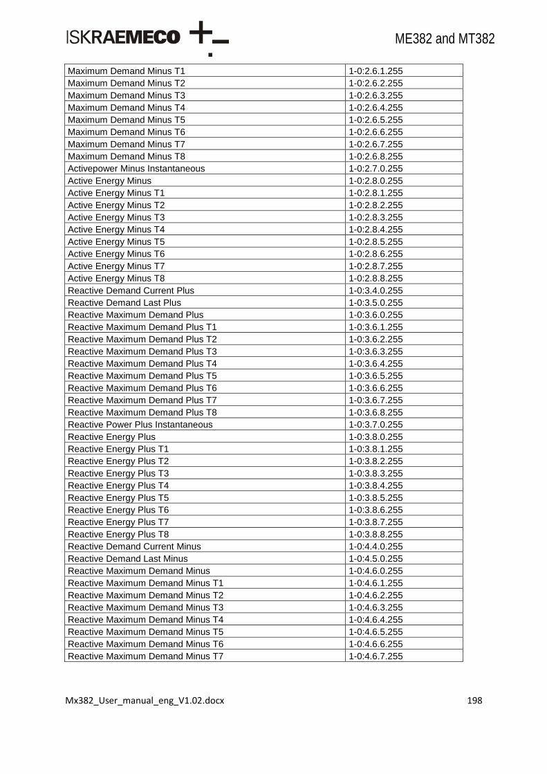
Mx382_User_manual_eng_V1.02.docx 198
ME382 and MT382
Maximum Demand Minus T1 1-0:2.6.1.255
Maximum Demand Minus T2 1-0:2.6.2.255
Maximum Demand Minus T3 1-0:2.6.3.255
Maximum Demand Minus T4 1-0:2.6.4.255
Maximum Demand Minus T5 1-0:2.6.5.255
Maximum Demand Minus T6 1-0:2.6.6.255
Maximum Demand Minus T7 1-0:2.6.7.255
Maximum Demand Minus T8 1-0:2.6.8.255
Activepower Minus Instantaneous 1-0:2.7.0.255
Active Energy Minus 1-0:2.8.0.255
Active Energy Minus T1 1-0:2.8.1.255
Active Energy Minus T2 1-0:2.8.2.255
Active Energy Minus T3 1-0:2.8.3.255
Active Energy Minus T4 1-0:2.8.4.255
Active Energy Minus T5 1-0:2.8.5.255
Active Energy Minus T6 1-0:2.8.6.255
Active Energy Minus T7 1-0:2.8.7.255
Active Energy Minus T8 1-0:2.8.8.255
Reactive Demand Current Plus 1-0:3.4.0.255
Reactive Demand Last Plus 1-0:3.5.0.255
Reactive Maximum Demand Plus 1-0:3.6.0.255
Reactive Maximum Demand Plus T1 1-0:3.6.1.255
Reactive Maximum Demand Plus T2 1-0:3.6.2.255
Reactive Maximum Demand Plus T3 1-0:3.6.3.255
Reactive Maximum Demand Plus T4 1-0:3.6.4.255
Reactive Maximum Demand Plus T5 1-0:3.6.5.255
Reactive Maximum Demand Plus T6 1-0:3.6.6.255
Reactive Maximum Demand Plus T7 1-0:3.6.7.255
Reactive Maximum Demand Plus T8 1-0:3.6.8.255
Reactive Power Plus Instantaneous 1-0:3.7.0.255
Reactive Energy Plus 1-0:3.8.0.255
Reactive Energy Plus T1 1-0:3.8.1.255
Reactive Energy Plus T2 1-0:3.8.2.255
Reactive Energy Plus T3 1-0:3.8.3.255
Reactive Energy Plus T4 1-0:3.8.4.255
Reactive Energy Plus T5 1-0:3.8.5.255
Reactive Energy Plus T6 1-0:3.8.6.255
Reactive Energy Plus T7 1-0:3.8.7.255
Reactive Energy Plus T8 1-0:3.8.8.255
Reactive Demand Current Minus 1-0:4.4.0.255
Reactive Demand Last Minus 1-0:4.5.0.255
Reactive Maximum Demand Minus 1-0:4.6.0.255
Reactive Maximum Demand Minus T1 1-0:4.6.1.255
Reactive Maximum Demand Minus T2 1-0:4.6.2.255
Reactive Maximum Demand Minus T3 1-0:4.6.3.255
Reactive Maximum Demand Minus T4 1-0:4.6.4.255
Reactive Maximum Demand Minus T5 1-0:4.6.5.255
Reactive Maximum Demand Minus T6 1-0:4.6.6.255
Reactive Maximum Demand Minus T7 1-0:4.6.7.255
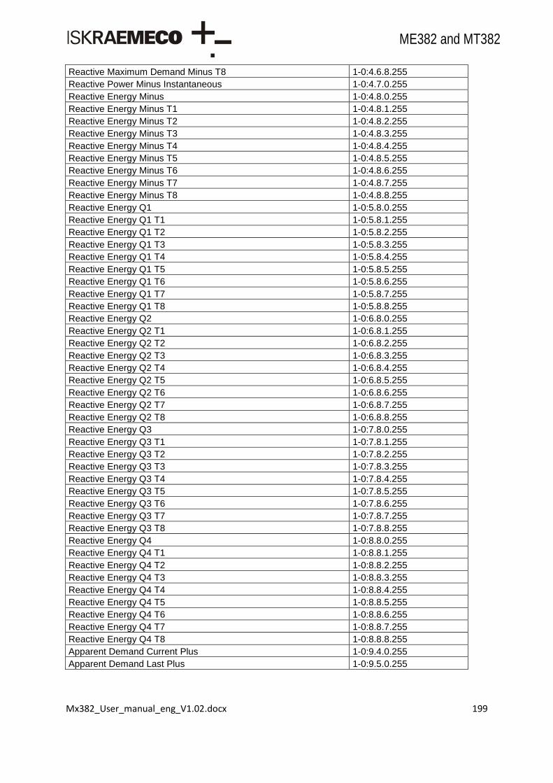
Mx382_User_manual_eng_V1.02.docx 199
ME382 and MT382
Reactive Maximum Demand Minus T8 1-0:4.6.8.255
Reactive Power Minus Instantaneous 1-0:4.7.0.255
Reactive Energy Minus 1-0:4.8.0.255
Reactive Energy Minus T1 1-0:4.8.1.255
Reactive Energy Minus T2 1-0:4.8.2.255
Reactive Energy Minus T3 1-0:4.8.3.255
Reactive Energy Minus T4 1-0:4.8.4.255
Reactive Energy Minus T5 1-0:4.8.5.255
Reactive Energy Minus T6 1-0:4.8.6.255
Reactive Energy Minus T7 1-0:4.8.7.255
Reactive Energy Minus T8 1-0:4.8.8.255
Reactive Energy Q1 1-0:5.8.0.255
Reactive Energy Q1 T1 1-0:5.8.1.255
Reactive Energy Q1 T2 1-0:5.8.2.255
Reactive Energy Q1 T3 1-0:5.8.3.255
Reactive Energy Q1 T4 1-0:5.8.4.255
Reactive Energy Q1 T5 1-0:5.8.5.255
Reactive Energy Q1 T6 1-0:5.8.6.255
Reactive Energy Q1 T7 1-0:5.8.7.255
Reactive Energy Q1 T8 1-0:5.8.8.255
Reactive Energy Q2 1-0:6.8.0.255
Reactive Energy Q2 T1 1-0:6.8.1.255
Reactive Energy Q2 T2 1-0:6.8.2.255
Reactive Energy Q2 T3 1-0:6.8.3.255
Reactive Energy Q2 T4 1-0:6.8.4.255
Reactive Energy Q2 T5 1-0:6.8.5.255
Reactive Energy Q2 T6 1-0:6.8.6.255
Reactive Energy Q2 T7 1-0:6.8.7.255
Reactive Energy Q2 T8 1-0:6.8.8.255
Reactive Energy Q3 1-0:7.8.0.255
Reactive Energy Q3 T1 1-0:7.8.1.255
Reactive Energy Q3 T2 1-0:7.8.2.255
Reactive Energy Q3 T3 1-0:7.8.3.255
Reactive Energy Q3 T4 1-0:7.8.4.255
Reactive Energy Q3 T5 1-0:7.8.5.255
Reactive Energy Q3 T6 1-0:7.8.6.255
Reactive Energy Q3 T7 1-0:7.8.7.255
Reactive Energy Q3 T8 1-0:7.8.8.255
Reactive Energy Q4 1-0:8.8.0.255
Reactive Energy Q4 T1 1-0:8.8.1.255
Reactive Energy Q4 T2 1-0:8.8.2.255
Reactive Energy Q4 T3 1-0:8.8.3.255
Reactive Energy Q4 T4 1-0:8.8.4.255
Reactive Energy Q4 T5 1-0:8.8.5.255
Reactive Energy Q4 T6 1-0:8.8.6.255
Reactive Energy Q4 T7 1-0:8.8.7.255
Reactive Energy Q4 T8 1-0:8.8.8.255
Apparent Demand Current Plus 1-0:9.4.0.255
Apparent Demand Last Plus 1-0:9.5.0.255

Mx382_User_manual_eng_V1.02.docx 200
ME382 and MT382
Apparent Maximum Demand Plus 1-0:9.6.0.255
Apparent Maximum Demand Plus T1 1-0:9.6.1.255
Apparent Maximum Demand Plus T2 1-0:9.6.2.255
Apparent Maximum Demand Plus T3 1-0:9.6.3.255
Apparent Maximum Demand Plus T4 1-0:9.6.4.255
Apparent Maximum Demand Plus T5 1-0:9.6.5.255
Apparent Maximum Demand Plus T6 1-0:9.6.6.255
Apparent Maximum Demand Plus T7 1-0:9.6.7.255
Apparent Maximum Demand Plus T8 1-0:9.6.8.255
Apparent Power Plus Instantaneous 1-0:9.7.0.255
Apparent Energy Plus 1-0:9.8.0.255
Apparent Energy Plus T1 1-0:9.8.1.255
Apparent Energy Plus T2 1-0:9.8.2.255
Apparent Energy Plus T3 1-0:9.8.3.255
Apparent Energy Plus T4 1-0:9.8.4.255
Apparent Energy Plus T5 1-0:9.8.5.255
Apparent Energy Plus T6 1-0:9.8.6.255
Apparent Energy Plus T7 1-0:9.8.7.255
Apparent Energy Plus T8 1-0:9.8.8.255
Apparent Demand Current Minus 1-0:10.4.0.255
Apparent Demand Last Minus 1-0:10.5.0.255
Apparent Maximum Demand Minus 1-0:10.6.0.255
Apparent Maximum Demand Minus T1 1-0:10.6.1.255
Apparent Maximum Demand Minus T2 1-0:10.6.2.255
Apparent Maximum Demand Minus T3 1-0:10.6.3.255
Apparent Maximum Demand Minus T4 1-0:10.6.4.255
Apparent Maximum Demand Minus T5 1-0:10.6.5.255
Apparent Maximum Demand Minus T6 1-0:10.6.6.255
Apparent Maximum Demand Minus T7 1-0:10.6.7.255
Apparent Maximum Demand Minus T8 1-0:10.6.8.255
Apparent Power Minus Instantaneous 1-0:10.7.0.255
Apparent Energy Minus 1-0:10.8.0.255
Apparent Energy Minus T1 1-0:10.8.1.255
Apparent Energy Minus T2 1-0:10.8.2.255
Apparent Energy Minus T3 1-0:10.8.3.255
Apparent Energy Minus T4 1-0:10.8.4.255
Apparent Energy Minus T5 1-0:10.8.5.255
Apparent Energy Minus T6 1-0:10.8.6.255
Apparent Energy Minus T7 1-0:10.8.7.255
Apparent Energy Minus T8 1-0:10.8.8.255
Voltage Underlimit Threshold 1-0:12.31.0.255
Voltage Underlimit Time Integral 1-0:12.31.129.255
Voltage Underlimit Counter 1-0:12.32.0.255
Voltage Underlimit Duration 1-0:12.33.0.255
Voltage Underlimit Magnitude 1-0:12.34.0.255
Voltage Overlimit Threshold 1-0:12.35.0.255
Voltage Overlimit Time Integral 1-0:12.35.129.255
Voltage Overlimit Counter 1-0:12.36.0.255
Voltage Overlimit Duration 1-0:12.37.0.255
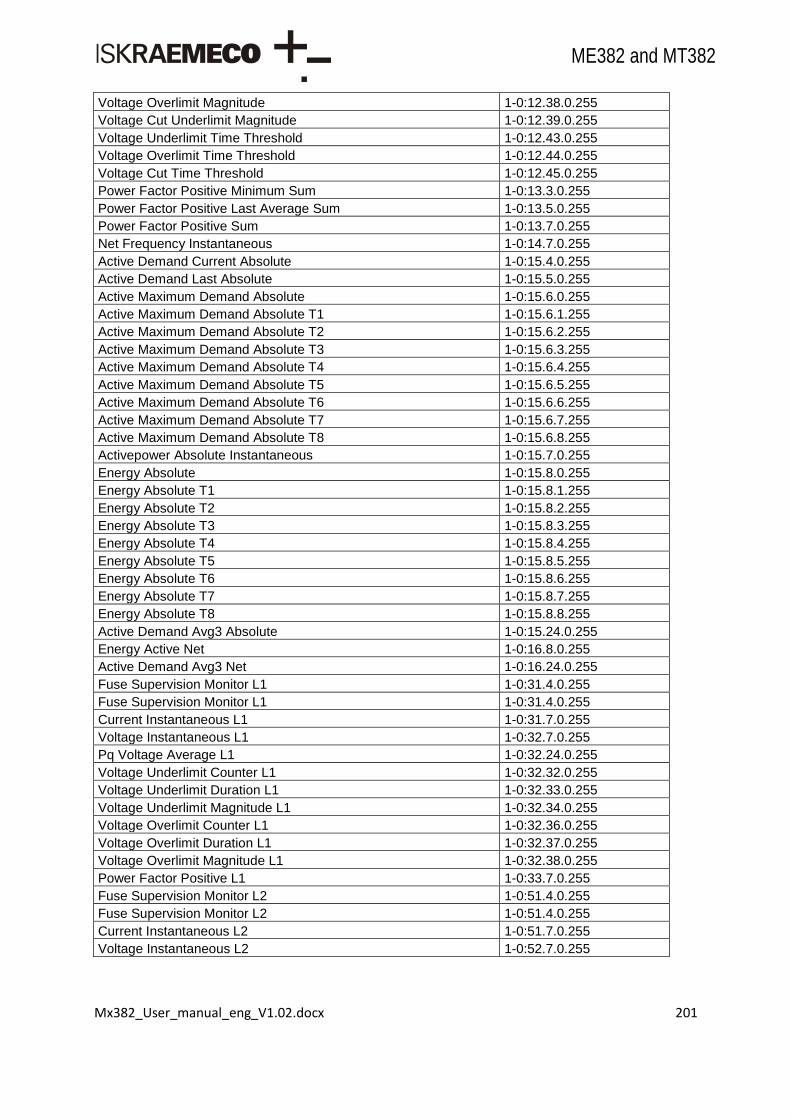
Mx382_User_manual_eng_V1.02.docx 201
ME382 and MT382
Voltage Overlimit Magnitude 1-0:12.38.0.255
Voltage Cut Underlimit Magnitude 1-0:12.39.0.255
Voltage Underlimit Time Threshold 1-0:12.43.0.255
Voltage Overlimit Time Threshold 1-0:12.44.0.255
Voltage Cut Time Threshold 1-0:12.45.0.255
Power Factor Positive Minimum Sum 1-0:13.3.0.255
Power Factor Positive Last Average Sum 1-0:13.5.0.255
Power Factor Positive Sum 1-0:13.7.0.255
Net Frequency Instantaneous 1-0:14.7.0.255
Active Demand Current Absolute 1-0:15.4.0.255
Active Demand Last Absolute 1-0:15.5.0.255
Active Maximum Demand Absolute 1-0:15.6.0.255
Active Maximum Demand Absolute T1 1-0:15.6.1.255
Active Maximum Demand Absolute T2 1-0:15.6.2.255
Active Maximum Demand Absolute T3 1-0:15.6.3.255
Active Maximum Demand Absolute T4 1-0:15.6.4.255
Active Maximum Demand Absolute T5 1-0:15.6.5.255
Active Maximum Demand Absolute T6 1-0:15.6.6.255
Active Maximum Demand Absolute T7 1-0:15.6.7.255
Active Maximum Demand Absolute T8 1-0:15.6.8.255
Activepower Absolute Instantaneous 1-0:15.7.0.255
Energy Absolute 1-0:15.8.0.255
Energy Absolute T1 1-0:15.8.1.255
Energy Absolute T2 1-0:15.8.2.255
Energy Absolute T3 1-0:15.8.3.255
Energy Absolute T4 1-0:15.8.4.255
Energy Absolute T5 1-0:15.8.5.255
Energy Absolute T6 1-0:15.8.6.255
Energy Absolute T7 1-0:15.8.7.255
Energy Absolute T8 1-0:15.8.8.255
Active Demand Avg3 Absolute 1-0:15.24.0.255
Energy Active Net 1-0:16.8.0.255
Active Demand Avg3 Net 1-0:16.24.0.255
Fuse Supervision Monitor L1 1-0:31.4.0.255
Fuse Supervision Monitor L1 1-0:31.4.0.255
Current Instantaneous L1 1-0:31.7.0.255
Voltage Instantaneous L1 1-0:32.7.0.255
Pq Voltage Average L1 1-0:32.24.0.255
Voltage Underlimit Counter L1 1-0:32.32.0.255
Voltage Underlimit Duration L1 1-0:32.33.0.255
Voltage Underlimit Magnitude L1 1-0:32.34.0.255
Voltage Overlimit Counter L1 1-0:32.36.0.255
Voltage Overlimit Duration L1 1-0:32.37.0.255
Voltage Overlimit Magnitude L1 1-0:32.38.0.255
Power Factor Positive L1 1-0:33.7.0.255
Fuse Supervision Monitor L2 1-0:51.4.0.255
Fuse Supervision Monitor L2 1-0:51.4.0.255
Current Instantaneous L2 1-0:51.7.0.255
Voltage Instantaneous L2 1-0:52.7.0.255
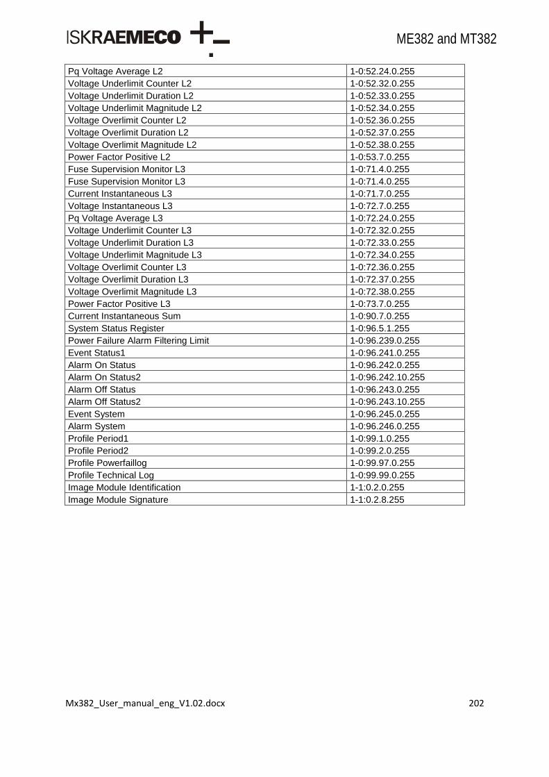
Mx382_User_manual_eng_V1.02.docx 202
ME382 and MT382
Pq Voltage Average L2 1-0:52.24.0.255
Voltage Underlimit Counter L2 1-0:52.32.0.255
Voltage Underlimit Duration L2 1-0:52.33.0.255
Voltage Underlimit Magnitude L2 1-0:52.34.0.255
Voltage Overlimit Counter L2 1-0:52.36.0.255
Voltage Overlimit Duration L2 1-0:52.37.0.255
Voltage Overlimit Magnitude L2 1-0:52.38.0.255
Power Factor Positive L2 1-0:53.7.0.255
Fuse Supervision Monitor L3 1-0:71.4.0.255
Fuse Supervision Monitor L3 1-0:71.4.0.255
Current Instantaneous L3 1-0:71.7.0.255
Voltage Instantaneous L3 1-0:72.7.0.255
Pq Voltage Average L3 1-0:72.24.0.255
Voltage Underlimit Counter L3 1-0:72.32.0.255
Voltage Underlimit Duration L3 1-0:72.33.0.255
Voltage Underlimit Magnitude L3 1-0:72.34.0.255
Voltage Overlimit Counter L3 1-0:72.36.0.255
Voltage Overlimit Duration L3 1-0:72.37.0.255
Voltage Overlimit Magnitude L3 1-0:72.38.0.255
Power Factor Positive L3 1-0:73.7.0.255
Current Instantaneous Sum 1-0:90.7.0.255
System Status Register 1-0:96.5.1.255
Power Failure Alarm Filtering Limit 1-0:96.239.0.255
Event Status1 1-0:96.241.0.255
Alarm On Status 1-0:96.242.0.255
Alarm On Status2 1-0:96.242.10.255
Alarm Off Status 1-0:96.243.0.255
Alarm Off Status2 1-0:96.243.10.255
Event System 1-0:96.245.0.255
Alarm System 1-0:96.246.0.255
Profile Period1 1-0:99.1.0.255
Profile Period2 1-0:99.2.0.255
Profile Powerfaillog 1-0:99.97.0.255
Profile Technical Log 1-0:99.99.0.255
Image Module Identification 1-1:0.2.0.255
Image Module Signature 1-1:0.2.8.255
Mx382_User_manual_eng_V1.02.docx 203
ME382 and MT382
Owing to periodically improvements of our products the supplied products can differ in some details from data stated in this user manual.
Iskraemeco d.d., Energy Measurement and Management
4000 Kranj, Savska loka 4, Slovenia
Telephone (+386 4) 206 40 00, Fax: (+386 4) 206 43 76
http://www.iskraemeco.si, E-mail: [email protected]
Published: Iskraemeco, Marketing, Data subjected to alteration without notice. Mx382_User_manual_eng_V1.02.docx
SMS Metering Limited41 London Road, Castle Court,Reigate, Surrey RH2 0DDTel: 0845 604 7244Email: [email protected]: www.smsmetering.co.uk
UK Distributor: