measurement and validation of fluid structure …umpir.ump.edu.my/id/eprint/8464/1/cd8159.pdf ·...
TRANSCRIPT
MEASUREMENT AND VALIDATION OF FLUID STRUCTURE
INTERFACE
MOHAMAD NORFAIZA ANUAR BIN MAHMOOD
MA09049
SUPERVISOR: MRS MIMINORAZEAN SUHAILA BT LOMAN
BACHELOR OF MECHANICAL ENGINEERING
UNIVERSITI MALAYSIA PAHANG
vi
ABSTRACT
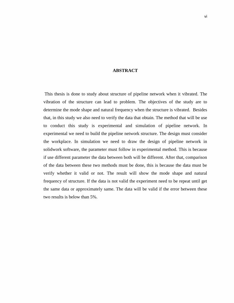
This thesis is done to study about structure of pipeline network when it vibrated. The
vibration of the structure can lead to problem. The objectives of the study are to
determine the mode shape and natural frequency when the structure is vibrated. Besides
that, in this study we also need to verify the data that obtain. The method that will be use
to conduct this study is experimental and simulation of pipeline network. In
experimental we need to build the pipeline network structure. The design must consider
the workplace. In simulation we need to draw the design of pipeline network in
solidwork software, the parameter must follow in experimental method. This is because
if use different parameter the data between both will be different. After that, comparison
of the data between these two methods must be done, this is because the data must be
verify whether it valid or not. The result will show the mode shape and natural
frequency of structure. If the data is not valid the experiment need to be repeat until get
the same data or approximately same. The data will be valid if the error between these
two results is below than 5%.

vii
ABSTRAK
Tesis ini dilakukan untuk mengkaji tentang struktur batang paip apabila bergetar.
Getaran pada batang paip boleh menyebabkan masalah. Objektif kajian ini adalah untuk
mengenal pasti bentuk modal dan kekerapan apabila struktur bergetar. Disamping itu,
tujuan kajian ini dibuat adalah untuk mengesahkan data yang diperolehi. Cara yang
digunakan dalam kajian ini adalah eksperimen dan simulasi. Di dalam eksperimen kita
perlu membina bahan kajian. Bentuk bahan kajian mestilah sesuai dengan tempat kita
melakukan kerja. Didalam simulasi kita perlu melukis mengunakan perisian solidwork,
data didalam lukisan mestilah same dengan data didalam eksperimen. Jika data berlainan
kita akan mendapat keputusan yang belainan. Selepas itu, kita perlu membangdingkan
data yang diperolehi diantara eksperimen dan simulasi. Pembangdingan perlu dilakukan
untuk mengesahkan data yang diperolehi. Data yang diperolehi sah jika peratusan di
antara simulasi dan eksperimentdi bawah 5 peratus.
viii
TABLE OF CONTENTS
Page
EXAMINER’S DECLARATION SUPERVISOR’S DECLARATION ii
SUPERVISOR’S DECLARATION iii
STUDENT’S DECLARATION iv
ACKNOWLEDGEMENTS v
ABSTRACT vi
ABSTRAK vii
TABLE OF CONTENTS viii
LIST OF TABLES xi
LIST OF FIGURES xii
LIST OF SYMBOLS xv
LIST OF ABBREVIATIONS xvi
CHAPTER 1 INTRODUCTION
1.1 Introduction 1
1.2 Objective 2
1.3 Problem Statement 3
1.4 Scope of study 3
1.5 Overview of study 4
CHAPTER 2 LITERATURE REVIEW
2.1 Introduction 5
2.2 Fluid structure phenomenon 6
ix
2.3 Fluid structure interaction coupling 7
2.4 90º elbow in pipeline 8
2.5 Fluid interaction on non rigid pipeline 9
2.6 Numerical method 9
2.7
2.8
2.9
2.10
2.11
Flexible liquid filled piping
Operational deflection shape
Modes
Modal analysis
Accelerometer sensor
10
11
13
14
19
CHAPTER 3 METHODOLOGY
3.1 Introduction 22
3.2 Flow chart 22
3.3 Gantt chart 24
3.4 Test rig and tool preparation 27
3.5 Procedure
3.5.1 Experimental
3.5.2 Simulation
36
36
38
CHAPTER 4 RESULTS AND DISCUSSION
4.1 Introduction 39
4.2 Simulation result 41
4.3 Experimental Result 49

x
4.3.1 X axes 50
4.3.2 Y axes 56
4.3.3 Z axes 61
4.4 Analysis result 66
CHAPTER 5 CONCLUSION AND RECOMMENDATIONS
5.1 Introduction 68
5.2 Conclusions 68
5.3 Recommendations 69
REFERENCES 70
APPENDICES
A Third Angle Projection for Test Rig 72
B Third Angle Projection for Elbow 73
C Third Angle Projection for Straight Line Pipe 74
D Third Angle Projection for Tee-Junction 75
E Solid Work for Straight Line Pipe 76
F
G
Solid Work for Tee-Junction
Properties of UPVC in ANSSY
77
78

xi
LIST OF TABLES
Table No. Page
4.4 Frequency and mode shape 66
4.4.1 Error between simulation and experimental 67
xii
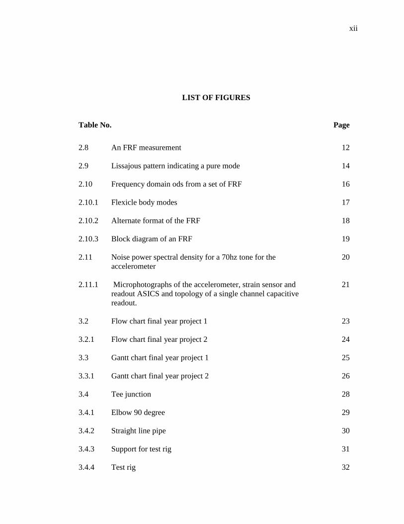
LIST OF FIGURES
Table No. Page
2.8 An FRF measurement 12
2.9 Lissajous pattern indicating a pure mode 14
2.10 Frequency domain ods from a set of FRF 16
2.10.1 Flexicle body modes 17
2.10.2 Alternate format of the FRF 18
2.10.3 Block diagram of an FRF 19
2.11 Noise power spectral density for a 70hz tone for the
accelerometer
20
2.11.1 Microphotographs of the accelerometer, strain sensor and
readout ASICS and topology of a single channel capacitive
readout.
21
3.2 Flow chart final year project 1 23
3.2.1 Flow chart final year project 2 24
3.3 Gantt chart final year project 1 25
3.3.1 Gantt chart final year project 2 26
3.4 Tee junction 28
3.4.1 Elbow 90 degree 29
3.4.2 Straight line pipe 30
3.4.3 Support for test rig 31
3.4.4 Test rig 32

xiii
3.4.5 Impact hammer 33
3.4.6 Accelerometer sensor 34
3.4.7 Data acquisition sensor 34
3.4.8 Modal testing layout 35
3.4.9 Dassy lab layout 36
3.5 Test rig in experiment 37
3.5.1 Test rig in solidwork 38
4.1 Structure of test rig in ME scope 40
4.2 Mode shape at frequency of 26.849hz 41
4.2.1 Mode shape at frequency of 31.59hz 42
4.2.2 Mode shape at frequency of 37.688hz 43
4.2.3 Mode shape at frequency of 44.86hz 44
4.2.4 Mode shape at frequency of 49.043hz 45
4.2.5 Mode shape at frequency of 57.726hz 46
4.2.6 Mode shape at frequency of 60.588hz 47
4.2.7 Mode shape at frequency of 64.424hz 48
4.3 Peak, mode shape and frequency at x axes 50
4.3.1 Mode shape at frequency 14.2hz 51
4.3.2 Mode shape atr frequency of 21.3hz 52
4.3.3 Mode shape at frequency of 32.4hz 53
4.3.4 Mode shape at frequency of 40.9hz 53
4.3.5 Mode shape at frequency of 58.8hz 54

xiv
4.3.6 Mode shape at frequency of 65.8hz 55
4.3.7 Peak, mode shape and frequency at y axes 56
4.3.8 Mode shape at frequency of 12.4hz 57
4.3.9 Mode shape at frequency of 21.6hz 57
4.3.10 Mode shape at frequency of 32.5hz 58
4.3.11 Mode shape at frequency of 40.4hz 59
4.3.12
4.3.13
4.3.14
4.3.15
4.3.16
4.3.17
4.3.18
4.3.19
4.3.20
4.4
Mode shape at frequency of 51.4hz
Mode shape at frequency of 64.3hz
Peak, mode shape and frequency for z axes
Mode shape at frequency of 14.3hz
Mode shape at frequency of 26.9hz
Mode shape at frequency of 34.7hz
Mode shape at frequency of 46.4hz
Mode shape at frequency of 51.9hz
Mode shape at frequency of 59hz
Graph between experiment and simulation
59
60
61
62
63
63
64
65
65
67

xv
LIST OF SYMBOLS
º Degree
µ Micro
%
c
Percentage
Celsius

xvi
LIST OF ABBREVIATIONS
Hz hertz
FRF Frequency response function
mg milligram
mm Millimeter
m Meter
CFD Computational fluid dynamic
FSI Fluid structure interaction
Pa Pascal
kg kilogram
1
CHAPTER 1
INTRODUCTION
1.1 INTRODUCTION
Measurement and validation of fluid structures in pipe line is important
nowadays. Measurement in fluid structural interface is to defined the properties
of leakages, besides that to defined the boundary condition if leakages in the
pipeline system. After that, we need to study to make a validation the properties
and boundary condition that had been defined using experimental result and
simulation. This is because in the industry of oil and gas is growing faster all
over the world. It had been a decade that pipe had been used to transfer the oil
and gas from the bottom sea to the ship, and from the ship to the land. This is
because it the easy way and more effectives. Industry of oil and gas had been the
most benefit financial for all over country. This is because industry of oil and gas
had been use in daily life such gas vehicle oil and to make the product that use at
home. Therefore if the pipe that uses to transfer the oil and gas is leak it will
cause a big disaster to the company. This because can lead to the financial and
natural issue. Besides that, it also will cause a problem to the environment. There
are methods that we can use to avoid the problem from happen such as make a
study what will make the piping system fatigue. From the method we can define
the properties of pipe that can show us the pipeline system is leak. The method
that we can use is fluid structural interaction. Besides that, we also can simulate
module of pipeline network. From the module we can obtain instantaneous

2
properties of data and analyzed it. To analyze it we will use finite element
method that is Fluid Structural interaction (FSI). Finite element is approach for
studying such a highly nonlinear problem in order to investigate the effect of
fluid structure interaction (FSI) in pipe lines. The FSI has got great attention in
recent years because of safety issue, reliability of plant set up, environmental
concern in pipe delivery system and plant performance. The Fluid Structure
interaction process basically deals with transfer of momentum and forces to pipe
system and fluid contained in it in an unsteady. The excitation process may be
caused by sudden change in flow and pressure or by some mechanical action
namely sudden closure of valve. The resulting load is transferred to pipe
supporting system. The friction coupling because of transient liquid stress will
act between pipe wall and fluid cause by the axial motion, (Suyash mishra, May
2012).
1.2 OBJECTIVES
The objectives of this project are to determine the leakage boundary that
may have in pipeline network. The study method that we will use in this project
is simulates the module of pipeline network by using the fluid structural
interaction software; the software that will use is Assy. In simulate the module of
pipeline we need to conduct the experiment to define the properties of pipe
leakages. Besides that, we also need to define the boundary condition of the
experiment. Furthermore we also need to define the operational deflection shape
that has in the fluid structural interaction. In the operational deflection shape we
need to define the boundary condition that will be used in the experiment.
Besides that, in this experiment we need to define the mode shape and natural
frequency that generate by the pipeline system. After that, we need to verify
whether the result that we obtain from experiment is valid or not.

3
1.3 PROBLEM STATEMENT
In the pipeline network it is hard to find the defect that may have. The
defect that may have is leakages and corrosion in the pipeline network. This will
give a serious issue to financial and natural resources. We need to conduct some
study to define the properties of data that can show the defect may have in
pipeline. We can obtained the data when do some study in the pipeline system. In
this study we need to find the properties of pipe leak by using experimental and
simulation of the pipeline network. The method that we will use to conduct this
study is by using the modal analysis. In fluid structure interaction analysis (FSI),
we need to simulate the module of pipeline network. When do the simulation of
the module in pipeline network. We need to define the properties of the pipe that
we will use. Modal analysis testing also can be use to determine the properties in
pipeline network.
1.4 SCOPE OF STUDY
In this study, we need conduct experiment by using test rig that we
design. The design must follow the real pipeline network. After that, we must do
simulation of the pipeline network. The aim of the experiment is to define the
properties of pipe leak in the pipeline system. We also can define the boundary
condition with the experiment method. In the experimental and the simulation we
will use modal analysis. From both we need to define the mode shape and natural
frequency of the pipeline system. To simulate the pipeline network we will use
fluid structure interaction simulation, the interaction process deals with transfer
of momentum and forces to pipe system and fluid contained in it in an unsteady.
In fluid structure interaction analysis (FSI) we will analyze the axial motion of
the fluid at the pipe wall. Fluid structure interaction also can analyze the
structures condition of the pipe at certain natural frequency and mode shape of
the structure. The mode shape will show the movement of the structure at the
certain frequency, from this result we can predict where the fatigue can happen.
4
After that, comparison of the result from the experiment and simulation must be
done, this is because we need to verify the result that we obtain is valid or not.
1.5 OVERVIEW OF STUDY
There is some chapter in this study. The overview of this study is to help reader
to better understanding. Chapter one is introduction, in this chapter it consists of
objective, problem statement and scope of study. Chapter one is important to help reader
understand why this study is done. Chapter two is about literature review, literature
review the summary of the journal from other thesis that had done the study. Chapter
three is methodology, in this chapter it consists of flow chart, gannt chart and procedure.
From this chapter we can know how the study is being conduct and the software that use
to conduct the study. Chapter four is the result of the study, at this chapter it shown the
result that obtained from experiment and simulation. The last chapter is conclusion, from
this chapter it consist of the conclusion that be made after done the experiment and the
suggestion about the study.
5
CHAPTER 2
LITERITURE REVIEW
2.1 INTRODUCTION
Fluid structure interaction is a method that commonly use all over the world to
do an experiment on the pipe or hollow material. Fluid structure interaction occur when
the fluid interrelate with the wall of the solid structure, this interface will produce waves
and apply the pressure the pressure on the surface of the solid structure and cause the
deformation of the solid structure and alter the flow by itself. The fluid interaction in the
pipeline may be coupling or axial loading and such of the interaction may be stable or
oscillatory, a crucial consideration in the design of many engineering system such as
aircraft. Fluid structure interaction is multifaceted physics problems happen in the flow
of the fluid causes the deformation of fluid structure that changes the boundary condition
of fluid problem. The concept of fluid structure interaction is flexible solid structure that
interaction of flowing flow is subjected to a pressure that can cause the deformation in
the structure of subject. When the interaction happen the solid structure will deformed
the structure follow the flow field. The flowing flow then will produce another form of
pressure on the structure and repeat the process; this interaction is called fluid structure
interaction (FSI). The fluid structure interaction can be divide into two that is strong and
weakly coupled. The first one is weakly couple system, if structure in the flow field or
containing fluid deform slightly or deform with the small amplitude, the effect will not
be considered the flow field because it has the low pressure. But the thermal stress in the
in the solid may be produce by the thermal gradient in the flow field, the flow field will
6
has small effect if the solid is deformed is too small. The second is strongly coupled
fluid structure system, if the alteration of the flow field due to big deformation or high
amplitude vibration of the structure cannot be neglected, large structure deformation or
displacement result in significant alteration of the original field but both altered and
original flow field cannot be linearly super imposed to each other, (Jong Chull Jo).
2.2 FLUID STRUCTURAL PHENOMENON
Fluid structure interaction in liquid filled system comprise two separate analysis
that undertaken sequentially. Usually a fluid transient code is use to defined the pressure
and flow velocities of the liquid, that are used as a input in a structure dynamic code that
is call uncoupled. The dynamic code has some limitation because it neglected the crucial
interaction between the liquid and the pipe. Pressure pulsation and mechanical vibration
in liquid transporting pipe system had an effect that affects the performance and the
safety of the pipeline system. The pipe motion contributes to the dynamic pressure to the
less restrained system. It will because the analyses of the fluid structure interaction
cannot be properly consider independent. When we compared the conventional analyses,
it may lead to higher or lower extreme pressure and stress in fluid structure interaction
analyses. Because of the change in natural frequencies there are more damping and
dispersion in the pressure and stress. There are many factor that need to be consider
when do fluid structure interaction, the factors that need to be consider is sources of
excitation or on possible responses to an citation. Excitation can be categorized into
single larger event or repetitive excitation. The factor that can be neglected liquid pipe
coupling, there are three type of liquid pipe coupling; friction, Poisson and junction
coupling. Friction and junction coupling happen along entire pipe also call as distributed
force. Junction coupling happens at the specific point (local forces) in the network.
Poisson coupling relate pressure in the liquid to axial stresses in the pipe through the
radial contraction and lead to precursors waves. Friction coupling is happen when there
are interaction between the pipe wall and the fluid, (D.J Leslie & A.E, 2001).
7
2.3 Fluid structure interaction coupling
The vibration in the piping system cannot be well understood by many pipework
designers, this because piping system has a complex phenomenon. Besides that, there
are just few guidelines to assist and no standard to help pipework designer to determine
if the system is at risk or not. Fluid structure interaction is use for unsteady flow that
interacts with the pipe vibration. The stationary flow can be consider as time averaged,
that because it includes turbulences and vortices, besides it contributed small velocity
and pressure fluctuation. There are four interaction mechanisms that caused the fluid
structure interaction on the liquid pipe system; the mechanism is friction coupling,
Poisson coupling, junction coupling and bourdon coupling. The friction coupling is act
between the liquid and axially vibrating pipe wall and it is mutual friction. Poisson
coupling is related to the pressure in the liquid that interact to the axial stress in the pipe
through the radial displacement of the pipe wall. Friction and Poisson coupling is act
along the entire pipe. Besides that, junctions coupling act where there is local force or
change in area or flow direction. Bourdon coupling just happen in the curved fluid filled
tubes of non circular cross section. The fluid flow will be changes if the internal fluid
pressure bend the tubes and externally imposed bending. In the transient event
dimensional or multi scale analysis will show the friction coupling is not important.
Although the Poisson coupling is small, it is important for modes of vibration that are
predominantly in the axial direction of the individual pipe because their effect may
accumulate in time. In junction coupling it is important when the excitation is to
generated to generate large unbalanced pressure forces in piping system. The axial,
radial, lateral and torsion direction is the direction of the pipe system vibrates. Pipe and
fluid will act together through Poisson and friction coupling in the axial vibration. The
liquid will act as added mass in the lateral vibration. But the liquid is not affecting the
torsion vibration, (A.S. Tijesseling, May 2002).

8
2.4 90o elbow in pipeline
90 elbows are to study the internal two phase flow induces variable forces on the
pipe bend. When separating the natural frequency of test section from the predominant
frequency of excitation forces we can obtain directly from force sensor the dynamic
force signal. When the gas flow rate increased and reached it maximum in annular flow
regime the root meant square value of force fluctuation also continuously increased. In
the recent year the internal two phase flow induced vibration on piping element had
giving awareness. The two phase flow is the fundamentally unbalanced in term of local
fluctuation of phase density, velocity, pressure, momentum flux among other
hydrodynamic parameter. The fluctuation may obligatory periodic forces on the piping
element that will transmit the fluid. When the piping natural frequency is close to the
excitation force the resonance may happen. Therefore to have a safe design and
operating of piping system we need to understand two phase internal flow induced
vibration mechanism. Yih and Griffith had been done to an experiment about
momentum flux fluctuation in two phase flow. Their do the experiment to measured the
interaction of response of a beam structure under the impact of two phase sup flow
coming out of vertical ducts. When they do the experiment by take the inverse transform
of the beam response they obtained the momentum flux of beam response. The result of
the experiment show that the maximum momentum fluctuation will be shown either in
high void slug or low void annular flow regime for a given total volumetric flow rate.
The unbalanced of momentum fluxes in small pipe was found to be better compared to
large pipe. In the experiment they also determine that system pressure, duct size and
shape did not have effect to the predominant fluctuation frequencies that less than 30 Hz,
(Yih and Griffith 1968). Tay and Thorpe was doing the experiment on 90 degree
horizontal elbow. Their objectives are the effects of liquid viscosity and surface tension
on the maximum forces interact on the elbow in oil pipeline. The results from the
experiment show that there is no significant effect on the maximum force with the
change of another property, (Tay and Thorpe 2004), (Yang liu, Shuichiromiwa, Takashi
hibiki, Mamoru ishii, Hideyuki morita, Yoshiyuki kondoh and Koichi tanimoto, 2012).

9
2.5 Fluid interaction on non rigid pipeline
Fluid structure interaction in non rigid pipeline system is following the water
hammer theory for the fluid coupled with beam theory for the pipe. Wave propagation
phenomena in the fluid and pipe wall induced transient. The axial, bending, shear and
torsion stress in the pipe wall will interact with the pressure waves in the fluid. When the
interaction between axial stress waves and fluid pressure happen it will also interact with
the radial expansion and contraction of the pipe wall. Besides that, interactive coupling
also will induce all type of wave at the junction, (A.G.T.J Heinsbroek, 1997).
2.6 Numerical method
The numerical method procedure is use get to get approximated solution for one
dimensional fluid structure interaction model. It has been use to analyses the transient in
the liquid filled piping system. Fluid structure interaction model is simulating by
hyperbolic partial differential equation system. Besides that, to describe and do
simultaneously pressure waves propagation in liquid as the axial, shear, and bending
waves that travelling in the pipe wall. Piping system is flowing liquid that follow the line
to some transient loading, when the momentum liquid in the piping change or piping
structure are abruptly happen because of in planning or accidental. Numerical method
also uses to precisely to calculate the hydrodynamic loading in the fluid as well as the
stress level and vibration in the piping. Three coupling mechanism had been determine
that is responsible for the induced of mechanical energy transfer between the fluid and
pipe, the three coupling are friction coupling, Poisson coupling and junction coupling.
The friction and Poisson coupling is act along the pipe and the junction coupling is at the
localized site such as elbow. Fluid transient shear stress induced the friction coupling but
it has less important than Poisson and junction coupling. The interaction between the
pressure pulse and the axial stress waves on the pipe wall is induced by the Poisson
coupling and it produce the Poisson ration coefficient. Junction coupling will induced

10
the pipe vibration, giving rise the existences, propagation and interaction of differ type
mechanical effort in the pipe, (RogerioGomes da Rocha and Felipe bastos de
FreitasRachid ).
2.7 Flexible liquid filled piping
Fluid structure interaction in piping system consists of conveys of momentum
and forces between piping and contains liquid through unsteady flow. Rapid change in
flow and pressure or mechanical accomplishment of the piping system may induce
excitation mechanism. The interaction on the wall of the pipe is manifested in pipe
vibration and perturbation in velocity and pressure of the liquid. Numerical advantages
allowed the practitioner to revert to the manner in which the interaction between the
piping and contained liquid to modeled. It is the enhanced technique that can help to
predict fluid structure interaction. The phenomenon of pipe movement is related to
unbalanced fluid flow. When there is change in flow, pressure or by mechanical motion
of the piping system it can produce excitation mechanism. The interaction of piping
system produces pipe vibration and perturbation in velocity and pressure of the liquid.
Poisson coupling, friction coupling and junction coupling is the mechanism that been
induced in piping system. Closed end, at the dead end of the pipe the pipe may
experiences some fluid forces. Because of that the pressure at the end will be double
because the deflection of the fluid. At the T section, the transmission and reflection of
pressure and stress waves’ unrestrained t shape. This because the mass and dimension of
the T piece is not been consider due to change in liquid momentum. The angle of the T
shape is assumed at 90 degree and it has no fluid structure interaction mechanism.
Column separation, dangerous liquid mat be created due to ambient pressure, (D.C
Wiggert and A.S Tijsseling, May 2001).

11
2.8 OPERATIONAL DEFLECTION SHAPE
Operating deflection can be defined as deflection of a structure at a particular frequency.
Besides that, operating deflection shape also can be define as any forced motion of two
or more point on a structure, from operating deflection shape we also can get mode
shape, this is because mode shape and operating deflection shape are related to each
other. Operating deflection shape and mode shape is inducing from the vibration of the
structure. Operating deflection shape and mode shape only induced in the resonant
vibration that has two degree off freedom vibration. Resonant vibration is the factor that
vibration problem occur in the structure. Vibration that happens in the structure is the
combination of two or more two degree of freedom force and resonant vibration force. If
we want to understand the vibration structure problem that happen, we need to defined
the resonant. The resonant that has in the structure that induced vibration is natural
frequency, modal damping and mode shape. The resonant vibration is induced when
there is interaction between the inertial and elastic properties in the structure, (B.J.
Schwarz and Mark H Richardson, October 1999).
12
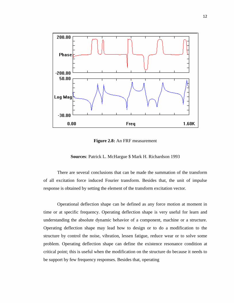
Figure 2.8: An FRF measurement
Sources: Patrick L. McHargue $ Mark H. Richardson 1993
There are several conclusions that can be made the summation of the transform
of all excitation force induced Fourier transform. Besides that, the unit of impulse
response is obtained by setting the element of the transform excitation vector.
Operational deflection shape can be defined as any force motion at moment in
time or at specific frequency. Operating deflection shape is very useful for learn and
understanding the absolute dynamic behavior of a component, machine or a structure.
Operating deflection shape may lead how to design or to do a modification to the
structure by control the noise, vibration, lessen fatigue, reduce wear or to solve some
problem. Operating deflection shape can define the existence resonance condition at
critical point; this is useful when the modification on the structure do because it needs to
be support by few frequency responses. Besides that, operating