measurement of vpn penformance between different - theseus
TRANSCRIPT

1
Guo Chao
MEASUREMENT OF VPN PENFORMANCE BETWEEN
DIFFERENT DEVICES
Bachelor’s Thesis Networking
May 2013
2
DESCRIPTION
Date of the bachelor's thesis
May, 2013
Author(s)
Guo Chao
Degree programme and option
Information Technology Networking
Name of the bachelor's thesis
Measurement of VPN performance between different devices Abstract
Network is becoming more and more important in daily life, the security is most critical issue in networking, however, when you add some security feature on your device, it will cost the resource, in this article we will test and measure how the VPN effect to your network. You can see from this article about the history of Internet and VPN, the architecture of VPN, how it works, and what kind of crypto algorithms VPN uses. The last one and also the most important of this article is the performance of VPN, you will see here what kind of effects VPN will take on your network, after that you can decide whether to use it. If you decide to use it, I will give some suggestions for improving the performance of your network. Subject headings, (keywords)
Internet, Security, IPsec, VPN, VPN Performance Pages Language URN
91
English
Remarks, notes on appendices
Tutor
Matti Koivisto
Employer of the bachelor's thesis
MAMK

3
CONTENTS
1. INTRODUCTION .................................................................................................. 1
1.1 What is VPN? ............................................................................................... 1
1.2 Aim of the thesis ........................................................................................... 1
1.3 Structure of thesis ......................................................................................... 1
2. DEVELOPMENT OF VPN TECHNOLOGY ........................................................ 2
2.1 History of VPN ............................................................................................. 2
2.2 Open System Interconnection Reference Model .......................................... 4
2.3 Early Layer 2 VPNs...................................................................................... 6
2.3.1 X.25 .................................................................................................... 6
2.3.2 Frame Relay (FR) .............................................................................. 7
2.4 Current Layer 2 VPN.................................................................................... 9
2.4.1 Multi-Protocol Label Switching ........................................................ 9
2.5 LAYER 3 VPN ........................................................................................... 11
2.5.1 Generic Routing Encapsulation ....................................................... 11
3. IP SECURITY ....................................................................................................... 12
3.1 Security Protocol ........................................................................................ 12
3.2 Working Mode ............................................................................................ 14
3.3 Security Association ................................................................................... 16
3.4 Key Management ....................................................................................... 17
3.5 Algorithms for authentication and encryption ............................................ 19
3.5.1 Diffie-Hellman ................................................................................. 19
3.5.2 Data Encryption Standard ................................................................ 20
3.5.3 Triple Data Encryption Standard ..................................................... 20
3.5.4 Advanced Encryption Standard ....................................................... 21
3.6 Type of IPsec VPN ..................................................................................... 22
3.6.1 Site-to-site VPN ............................................................................... 22
3.6.2 Remote access VPN ......................................................................... 23
4. DESIGN AND IMPLEMENTATION OF TEST VPN ......................................... 24
5. DESIGN IMPLEMENT AND MEASURE OF IPSEC VPN ............................... 26
5.1 Measurement between two Cisco 2911 routers .......................................... 26
5.2 Measurement between two Cisco 2911 routers with VPN ......................... 28
5.3 Measurement between two Smoothwall firewall with VPN ...................... 35
5.4 Measurement between two Cisco 2811 routers with VPN ......................... 40
5.5 Measurement between two Cisco ASA 5505 firewalls .............................. 42
6. CONCLUSION ..................................................................................................... 51
7 BIBLIOGRAPHY ................................................................................................. 52
8. APPENDIX ........................................................................................................... 53

1
1. INTRODUCTION
Internet is more and more important in our daily life, so that the security of Internet is
also becoming more and more significant. One of the most vital matters is how to
carry our data in a secure way over the public Internet. One popular solution is Virtual
Private Network (VPN).
1.1 What is VPN?
Virtual Private Network (abbreviated VPN) refers to the technology to establish a
private network in the public network. It is a virtual network, mainly because of the
connection between any two nodes of the entire VPN is not a physical link which
traditional private network uses. Instead, it builds a logic network on top of the
platform which an ISP provides, for example, Internet, Asynchronous Transmission
Mode (ATM), Frame Relay (FR) and so on. And the users’ data is transmitted in the
logical link. VPN uses tunneling technology, encryption and decryption, key
management, user and device identity authentication technologies. It covers the
package across the shared or public networks, the encryption and authentication
validation link, expansion of the private network.
1.2 Aim of the thesis
The theoretical aim of this thesis is to find out how IPsec VPN works. The first thing
to study is IPsec protocol, ESP or AH. Followed by the encryption algorithm used for
confidentiality, the normal algorithms include DES, 3DES or AES. Next thing to get
familiar with is the hash algorithm used for the data integrity, the main alternatives are
MD5 or SHA. The fourth thing to study is the method used for sharing the secret key.
There are two ways we use very often: Pre-shared Keys (PSKs) or Digital Certificates
(for example, RSA). The last thing we will touch is the DH algorithm used for secure
key exchange, such as DH Group 1, 2, 5 and so on.
The practical aim of this thesis is to analyze how the use of a VPN affects to the
network performance. Because VPNs can be implemented with different devices, I
carry out measurements with different configurations including a VPN between two
routers, between two firewalls and in a hybrid case between a router and a firewall.
1.3 Structure of thesis
The structure of the thesis is as follow: Chapter 2 reveals the theory of different
implementation methods of VPN, such as what we were using in the past and what we
are using now. We will discuss little deeper in current VPN technology in Chapter 3.
Chapter 4 includes the description of the test environment for VPN performance

2
analyses. In Chapter 5, we will compare the performance between different devices.
Chapter 6 dedicates to give a conclusion and summary of this thesis.
2. DEVELOPMENT OF VPN TECHNOLOGY
2.1 History of VPN
When you want to talk about VPN, one thing you cannot avoid to say is the Internet,
because if there is no Internet, there will be no VPN.
The Internet was developed from the basics of APRANET, which was a computer
network once used by American military. In 1969, the U.S. Defense Advanced
Research Projects Agency (ARPA) began to establish a network named ARPANET.
The purpose to establishing this network was justified by military necessity. It set up a
computer network with fault tolerance. If part of the network is destroyed, the rest of
the network will soon establish a new link. It is generally considered the prototype of
Internet. (Yang, 2005)
In 1983, ARPANET broke into two parts, one called ARPANET, and the other one
called MILNET that was only for military use. The generation of Local Area Network
(LAN) and Wide Area Network (WAN) made a big contribution to the development
of Internet. One of the most important organizations is National Science Foundation
(NSF). (Softhouse, 2013)
National Science Foundation (NSF) began to establish a computer network NSFNET
in 1985. NSF was planning to build five Supercomputer Centers and a Nationwide
Education and Research Network, which was a nationwide scale NSFNET used to
support scientific research and education, and based on these to connect to other
networks. When MILNET (separated by ARPANET) connected with NSFNET in
1989, the name Internet began to be used. After all, the computer network of the other
departments incorporated into the Internet, ARPANET dissolved.
The biggest contribution of NSFNET made to Internet was that it opened it to the
society, instead of government and research use only. In 1990, Merit, IBM, and MCI
built the nonprofit organization- Advanced Network & Science Inc. together. The aim
of ANS was to build a nationwide T3 backbone network, and make it possible to
transmit data at 45 Mbps. To the end of 1991, NSFNET’s entire backbone network
interconnected with ANS’s T3 backbone network. (Softhouse, 2013)
The early 1990s, commercial organizations began to enter the Internet. They found
that the Internet had a big potential in communication, searching information and
customer service. Therefore, the Internet experience new phase of commercialization,
and the commercial organizations became a strong force of Internet development. In

3
1995, NSFNET stop working and the Internet became thoroughly commercialized.
(Yang, 2005)
When we talk about the Internet, there is another thing we have to talk about, TCP/IP.
In 1974, a set of protocols was published, which included famous Internet Protocol
(IP) and Transmission Control Protocol (TCP). These two protocols work together. IP
supports the basic communication, and TCP makes the IP communication reliable and
stable.
The most important characteristic of TCP is openness, which means all the standards
of TCP/IP and technology of Internet are open. The purpose is to make any device
able to communicate with each other no matter which manufacture makes them, and
another one is to make an open system for the Internet. They are important reasons
why the Internet developed so quickly, as shown in FIGURE 2.1.
FIGURE 2.1 Internet users by development level, 2003-2013, and by region,
2013(ITU World Telecommunication /ICT Indicators database)
The Internet grew bigger day by day, and as a result of that, there are not only the
people who share information but also the people who steal others’ information
(nowadays, we call them hackers). At the beginning, the hackers’ behaviors just
limited to macro viruses that cause software and operating systems to work slowly or
crash. Eventually, the sniffer software and Trojan horse appeared to steal users’
passwords. Today, hackers are using high technology and they are familiar with
everything related to computer, software, hardware, network, and operating systems.
Their attacks include ping of death, along with sessions hijacking and backdoor
command raids. It makes people pay more attention to security than ever before
especially in business area. (David, 1999)
The first choice to protect against hackers is to build your own private networks, but it
is really too expensive, and hard to manage and maintain as well. Finally, VPN
becomes another solution that can carry data securely over the public Internet. The
advancements of VPN are combining authentication and encryption together, using
tunneling protocol to build a virtually private network over the public network. In
other words, VPNs enable you to build and operate an enterprisewide network fully
4
resistant to hackers’ attacks. It is also a good replacement of building an expensive
private network. (David, 1999)
VPN is a remote access technology, which builds a private network on the top of
public network. For example, when a company employee travels to another city, he
wants to access the corporate intranet server resources, and this kind of access is a
remote access. How to make the staff access to internal network resources? VPN
solution is to set up a VPN server in intranet network. The VPN server has two
network interface cards, one connected to the intranet network, another connection to
the public network. Staff connected to the Internet, find a VPN server, and then he/she
can connect to the corporate intranet. In order to ensure data security, the
communication between a VPN server and a client is encrypted. With data encryption,
you can think that the data is in a dedicated data link for secure transmission, just like
a private network specially erected. VPN actually uses the common link on the
Internet, and therefore can only be called a virtual private network. Namely: VPN is
essentially the use of encryption technology to encapsulate a data communication
tunnel which transmits data on the public Internet. With VPN technology, either inside
or outside home office, as long as the Internet is accessed, you will be able to use
VPN to access internal network resources. That is why VPN is used so widely used in
the enterprise environment.
2.2 Open System Interconnection Reference Model
At the beginning of the Internet, there were many communication frameworks. The
result was if you choose one’s framework, you must choose their products and only
can connect to the network that is using the same framework as you. Fortunately, the
International Organization for Standardization (ISO) published the Open System
Interconnection reference model. It is aimed to provide a framework of open system
protocol. The framework is shown in FIGURE 2.2.

5
FIGURE 2.2 Basic architecture of OSI (www.c-sharpcorner.com)
The physical layer protocol describes the mechanical, electrical, functional and
operating method to activate, maintain and deactivate the physical connection for bit
transmission between network devices. (Cisco, 2008) In other words, it is responsible
for the information coded into the current pulses or other signals for transmission over
the Internet. (Sina, 2007)
Date Link layer used for exchanging date frames between devices over a public media.
(Cisco, 2008) It provides reliable data transmission through the physical network.
(Sina, 2007)
Network layer provide the service to exchange the pieces of data over the network
between different terminal devices. (Cisco, 2008) It is responsible for set up a link
between source and terminal. (Sina, 2007)
Transport layer defines services to segment, transfer, and reassemble the data for
individual communications between the end devices. (Cisco, 2008) It also supports an
end-to-end network data stream to high-lever layers. (Sina, 2007)

6
Session layer provides services for Presentation layer to organize its dialogue and to
manage data exchange. (Cisco, 2008) It means that session layer establishes, manages
and terminates the communication between session layer and others. (Sina, 2007)
Presentation layer sets the rule for the data transfer between different services of
Application layer. (Cisco, 2008) If in detail, it means that presentation layer provides
multiple functions used for application layer’s data coding and transformation, make
sure that the information transmitted by one’s application layer can be understand by
another’s. (Sina, 2007)
Application layer provide the way to connect the end-to-end network by using data
network for different people in the human network. (Cisco, 2008) This is the layer
closest to the end users, which means that the interaction between user and application
is directed. Please note, the application layer is not software running on the computer,
but an application program interface that provides application to access to the Internet,
such software program is beyond the scope of the OSI model. (Sina, 2007)
2.3 Early Layer 2 VPNs
Before describing the current VPN protocols, I introduce some examples of early
layer 2 VPNs. The protocols introduced here are X.25 and Frame Relay.
2.3.1 X.25
X. 25 protocol is a protocol recommended by the International consultative committee
on telecommunications and Telegraph (CCITT). It defines the terminals and
computers connections to a packet switched network (PSN). The packet switched
network is a network in which data packet select the route to reach the destination. X.
25 is a very easy way to achieve the packet switched service. Traditionally, PSN used
for connecting the remote terminal to the host system. Such services provided the
users, who use the same service at the same time, any-point-to-any-point connection.
The different users’ signals from the same network can enter the PSN by multiplexer
via X. 25 interface and distributed to different remote locations. X.25 interface can
support up to 64Kbps, CCITT re-defined the standards in 1992 and improve the rate
to 2.048Mbps. Today, X.25 is only used on old networks in some developing
countries. In Europe, it is only used for GPS tracking and on wireless packet radio
networks. (Sosinsky, 2009)
The X.25 conncets the Data Terminal Equipment (DTE) with Data Communication
Equipment (DCE) by using Virtual Circuits (VC). VCs can be devided into two
cagegories: Switch Virtual Circuit (SVC) and Permanent Virtual Circuit (PVC).
7
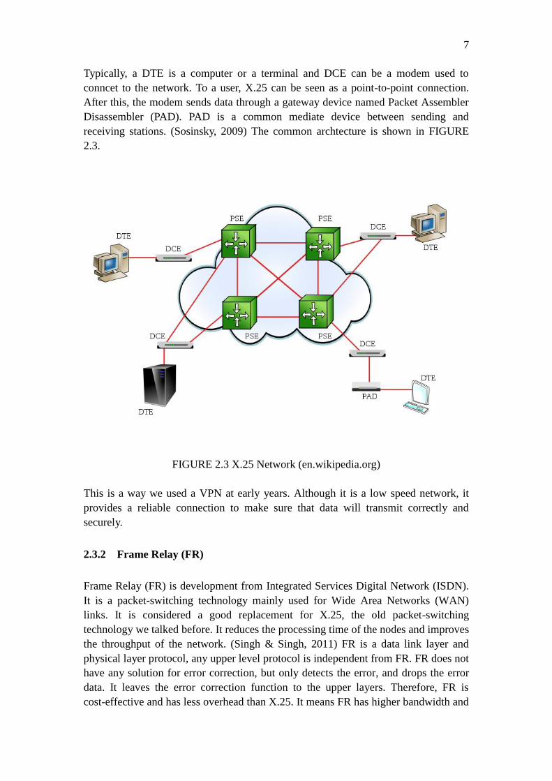
Typically, a DTE is a computer or a terminal and DCE can be a modem used to
conncet to the network. To a user, X.25 can be seen as a point-to-point connection.
After this, the modem sends data through a gateway device named Packet Assembler
Disassembler (PAD). PAD is a common mediate device between sending and
receiving stations. (Sosinsky, 2009) The common archtecture is shown in FIGURE
2.3.
FIGURE 2.3 X.25 Network (en.wikipedia.org)
This is a way we used a VPN at early years. Although it is a low speed network, it
provides a reliable connection to make sure that data will transmit correctly and
securely.
2.3.2 Frame Relay (FR)
Frame Relay (FR) is development from Integrated Services Digital Network (ISDN).
It is a packet-switching technology mainly used for Wide Area Networks (WAN)
links. It is considered a good replacement for X.25, the old packet-switching
technology we talked before. It reduces the processing time of the nodes and improves
the throughput of the network. (Singh & Singh, 2011) FR is a data link layer and
physical layer protocol, any upper level protocol is independent from FR. FR does not
have any solution for error correction, but only detects the error, and drops the error
data. It leaves the error correction function to the upper layers. Therefore, FR is
cost-effective and has less overhead than X.25. It means FR has higher bandwidth and

8
lower delay than X.25. (Encyclopedia, 2006)
Because FR is also a packet-switching network, it works similar to X.25. It breaks the
data into pieces, which are called frames in FR. The frame of FR has a variable length
and the length depends on the workload of the FR network. FR works on virtual
circuit as well. VC can also be SVC or PVC, it depends on if you just need a
temporary connection or a reliable point-to-point connection. Although FR does not
have any error-correction function, FR has congestion control. These congestion
controls include: Committed Information Rate (CIR) used for throughput in normal
condition, Committed Burst Size (CB) used for largest rate allowed, and Excess Burst
Size (BE) used for additional rate but not guaranteed (Sosinsky, 2009). Forward
Explicit Congestion Notification (FECN) is used for informing the DTE there is
congestion in the path from source to destination. Backward Explicit Congestion
Notification (BECN) is used for transferring the frame opposite way of FECN. The
basic structure of a FR network is shown below as FIGURE 2.4.
FIGURE 2.4 Logical Frame Relay (astorinonetworks.com)

9
FIGURE 2.5 Standard Frame Relay frame (Cisco, 2008)
FIGURE 2.5 above shows the structure of a standard frame relay frame. The biggest
size of a frame is 1600 bits, 16 bits for address, 16 bits for Frame Check Sequence
(FCS), 16 bits for flag, and others are all for data. Frame Check Sequence is for
error-correction function, it will calculate a value before transmit. After the frame
arrives the destination, the terminal will calculate a value and compare it to the FCS.
If they are the same, FR will forward it to the upper layer. If they are not the same, the
frame will be dropped. The next thing is Data Link Connection Identifier (DLCI).
DLCI is stored in the address field of each data frame. It is used to tell how to
transmit the data frame. DLCI only has local significance, which means these values
are not always same in FR network. DLCI only identifies the Virtual Circuit (VC) to
the end-point. DLCI does not make any sense to signal link. Two different devices
connected by VC can use different DLCI to show a same connection. (Cisco, 2008)
Because FR uses PVCs and provides a point-to-point connection, with higher
bandwidth and lower delay, so it is a good replacement of X.25. It is a good choice to
improve the speed and provides good security.
2.4 Current Layer 2 VPN
After the early layer 2 protocols, now let’s see what we are using nowadays.
2.4.1 Multi-Protocol Label Switching
The Multi-Protocol Label Switching (MPLS) technology was a network switching
technology proposed by Internet Engineering Task Force (IETF) in 1997. It mainly
adds the connection-oriented feature in traditional IP network and uses openness and
flexibility of IP technology to improve the exchange rate of network. It also reduces
the complexity of the network. That is why MPLS has become more and more

10
popular. (Chen, 2011)
The basic unit of the MPLS network is Label Switching Router (LSR). The node at
the edge of the network is called Label Edge Router (LER), and the core node of the
network is called LSR. LER node in MPLS network is responsible for entering and
exiting of IP packet; LSR node is responsible for high-speed packet switching. Every
packet coming into MPLS network will be defined as specified Forwarding
Equivalence Class (FEC). Each FEC will encode into a short but fixed-length value
that is called label. The label between devices released by Label Distribution Protocol
(LDP). MPLS still needs to run routing protocol between LSR and LER, LSR and
LSR. Then based on the routing information, devices decide the Label Switching Path
(LSP). (Wang, 2011)
When an IP packet comes to the ingress of a large LER network, the ingress LER will
analyze the header of the packet, and search the routing table to determine the LSP to
destination. Finally, it inserts the corresponding LSP label into the header. After this
process, the packet will be forwarded to the LSP that the label shows. The node in the
network will forward the packet based on the IP header’s label, so there is no need to
look up the routing table repeatedly. When the packet comes to the egress of LSR, the
LSP will strip the label of the packet. Afterwards, the packet will be forwarded to
destination following the normal IP routing. (Chen, 2011) MPLS network structure is
shown in FIGURE 2.6.
FIGURE 2.6 MPLS structure (www.freepatentsonline.com)
As the feature described previous, MPLS is very suitable for VPN. It will improve the

11
performance of VPN, and the data transmit in LSR network cannot be seen. They are
all in FEC with label, so that is why MPLS is popular in current networks.
2.5 LAYER 3 VPN
2.5.1 Generic Routing Encapsulation
Generic Routing Encapsulation (GRE) is a protocol that encapsulates one protocol
over another protocol. It was published in 1994 by IETF. (Hanks, 1994) GRE not only
supports the IP protocol, but also other kinds of network layer protocol. It allows any
kind protocol’s data packet to be payload packet and encapsulate it into any other kind
protocol’s data packet. (Wang, 2005)
The GRE protocol datagram format is composed of three parts: the Delivery Header,
GRE header and Payload packet. (Hanks, 1994) The GRE protocol stack is shown in
FIGURE 2.7.
FIGURE 2.7 GRE protocol stack (RFC 1701)
Seen from FIGURE 2.7, the payload packet is the data that the user wants to transmit,
and it is the data that should be encapsulated as well. GRE header is used to establish,
maintain and end the tunnel. It will encapsulate the payload packet, add the GRE
header, then put these two parts into IP data field, and finally transmit them by IP.
Delivery Header is added by delivery protocol, which is used for transmitting the
encapsulated GRE header and payload packet. For example, IP protocol is the most
common transport protocol, normally, we use IP protocol to transmit GRE protocol.
(Zeng, 2012)
12
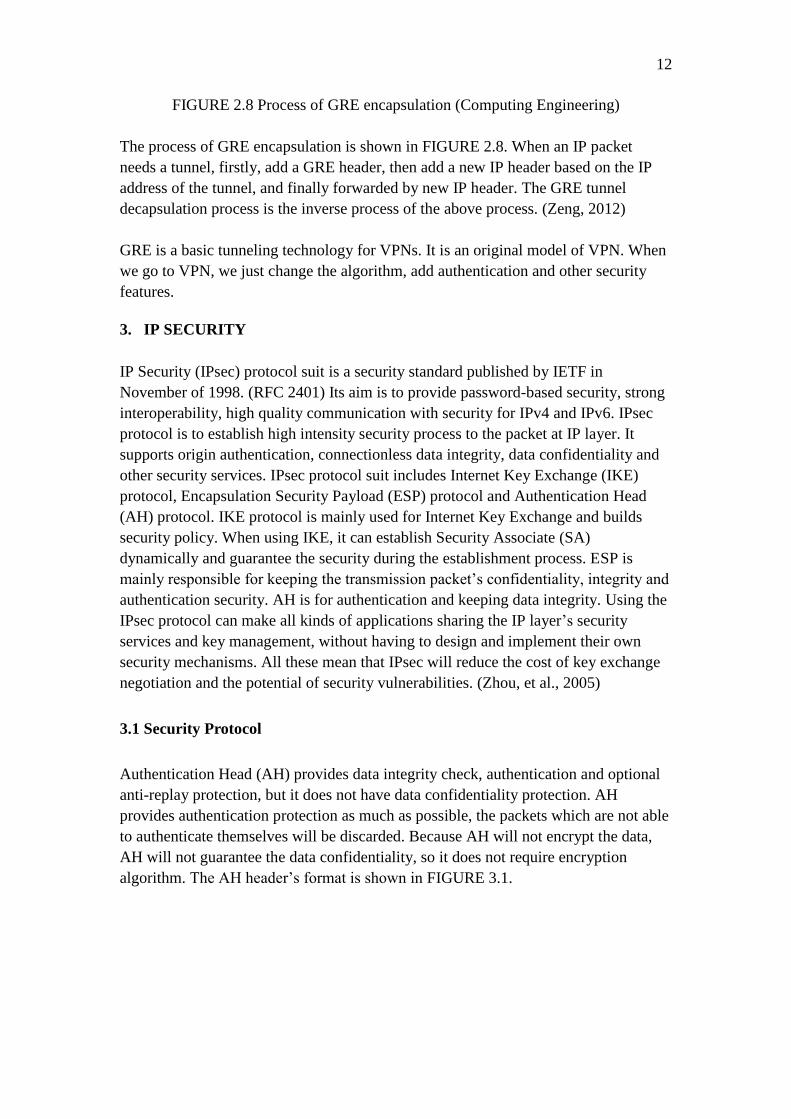
FIGURE 2.8 Process of GRE encapsulation (Computing Engineering)
The process of GRE encapsulation is shown in FIGURE 2.8. When an IP packet
needs a tunnel, firstly, add a GRE header, then add a new IP header based on the IP
address of the tunnel, and finally forwarded by new IP header. The GRE tunnel
decapsulation process is the inverse process of the above process. (Zeng, 2012)
GRE is a basic tunneling technology for VPNs. It is an original model of VPN. When
we go to VPN, we just change the algorithm, add authentication and other security
features.
3. IP SECURITY
IP Security (IPsec) protocol suit is a security standard published by IETF in
November of 1998. (RFC 2401) Its aim is to provide password-based security, strong
interoperability, high quality communication with security for IPv4 and IPv6. IPsec
protocol is to establish high intensity security process to the packet at IP layer. It
supports origin authentication, connectionless data integrity, data confidentiality and
other security services. IPsec protocol suit includes Internet Key Exchange (IKE)
protocol, Encapsulation Security Payload (ESP) protocol and Authentication Head
(AH) protocol. IKE protocol is mainly used for Internet Key Exchange and builds
security policy. When using IKE, it can establish Security Associate (SA)
dynamically and guarantee the security during the establishment process. ESP is
mainly responsible for keeping the transmission packet’s confidentiality, integrity and
authentication security. AH is for authentication and keeping data integrity. Using the
IPsec protocol can make all kinds of applications sharing the IP layer’s security
services and key management, without having to design and implement their own
security mechanisms. All these mean that IPsec will reduce the cost of key exchange
negotiation and the potential of security vulnerabilities. (Zhou, et al., 2005)
3.1 Security Protocol
Authentication Head (AH) provides data integrity check, authentication and optional
anti-replay protection, but it does not have data confidentiality protection. AH
provides authentication protection as much as possible, the packets which are not able
to authenticate themselves will be discarded. Because AH will not encrypt the data,
AH will not guarantee the data confidentiality, so it does not require encryption
algorithm. The AH header’s format is shown in FIGURE 3.1.

13
FIGURE 3.1 AH format (RFC 2402)
Next header is an 8-bits long field. It is used for distinguish next AH’s type. Payload
is 8-bits long and it describes AH’s length. It works by minus 2 in each 32 bits.
Reserved is a 16-bits field. It is reserved for future use. Security Parameters Index
(SPI) has an arbitrary 32-bits length. It is used to identify the Security Association
(SA) of incoming packet. Sequence Number Field is a 32-bits long field and it is used
for anti-replay service. Authentication Data is a variable-length field that includes
Integrity Check Value (ICV). The space must be an integral multiple of 32 bits (IPv4
or IPv6) in length. (Stephen & Randall, 1998)
The biggest different between Encapsulating Security Payload (ESP) and AH is that
ESP will encrypt the payload part. It means that ESP provides confidentiality against
variable attack types. The ESP’s format is shown in FIGURE 3.2.
FIGURE 3.2 ESP format (RFC 2406)
The other parts of ESP have the same function as AH. The only difference is Padding
part. The padding part has a variable-length field. Whether to use this part is depended

14
on whether encrypt the payload data. Pad length is specified by encryption algorithm.
指定的源无效。
3.2 Working Mode
IPsec support transport mode and tunnel mode, both AH and ESP support these two
modes.
Transport mode provides security protection for the upper layer. It means that it
protects the IP packet payload or upper layer protocols (such as TCP, UDP, and
ICMP). It will be shown in FIGUREs 3.3 to 3.6. When a host runs AH or ESP, IPv4’s
payload means the data after IPv4 header. For IPv6, it is IPv6 Hop-by-Hop extension
header, or IPv6 Destination extension headers. (He, 2002)
FIGURE 3.3 Transport IPv4 (AH) (RFC 2402)
FIGURE 3.4 Transport IPv6 (AH) (RFC 2402)

15
FIGURE 3.5 Transport IPv4 (ESP) (RFC 2406)
FIGURE 3.6 Transport IPv6 (ESP) (RFC 2406)
Tunnel mode provides protection for the entire IP packet. In tunnel mode, it will add a
AH or ESP fields for the original IP packet firstly, and then add a new external IP
header. All original or internal packets will be forwarded through one IP network’s
end to another. All the routers on the path only check the external header, but not the
original header. Because of adding a new IP header, the destination address of new
header may be not the same with the original one. Typically, tunnel mode is used
when there is at least one security gateway, such as a firewall or a router. When using
tunnel mode, the hosts after the security gateway can use private addresses to
communicate with each other without implementing IPsec. The common structure is
shown in FIGURE 3.7 and 3.8. (He, 2002)

16
FIGURE 3.7 Tunnel mode (AH) (RFC 2402)
FIGURE 3.8 Tunnel mode (ESP) (RFC 2406)
3.3 Security Association
The Security Association (SA) is the basis of the IPsec key management. Both AH
and ESP are using SA, and the main function of IKE protocol is to establish and
maintain SA. SA is a simple connection that is established by two communication
terminals after negotiations. SA also defines protocol type, encryption algorithms,
authentication methods, encryption and authentication keys, key survival time, as well
as anti-replay of security services. SA can be established either manually or using IKE
protocol automatically.
SA is one directional. If two hosts are using ESP to communicate, host A needs to use
one outgoing packet SA (out), also an incoming packet SA (in). Host A’s SA (out)
and host B’s SA (in) share the same encryption key. Host A’s SA (in) and host B’s
SA (out) use the same encryption key. SA can provide the security service for both
AH and ESP, but not at the same time. If you want to use AH and ESP simultaneously,
you need to establish two (maybe more than two) SAs. In order to guarantee two-way

17
communication between two hosts or security gateways, you need to create at least
two SA (one in each direction).
There are two types of SA (transport mode and tunnel mode). Transport mode SA is
between two hosts. In IPv4, transport mode’s security header follows IP header and
any optional fields, before other upper layer’s protocol (such as TCP, UDP). In IPv6,
security header appears after basic IP header and extender IP header and before any
other upper layer’s protocol. Tunnel mode’s SA is almost used for IP tunneling. If any
one of the communication terminal is a security gateway, SA must be in tunnel mode.
Therefore, the SA between two security gateways, one host and one security gateway
is always tunnel mode. Note, although the SA between two security gateways can be
tunnel mode, it can also support transport mode. For example, the gateway participate
a communication, which the gateway is a destination, as a normal gateway (such as
ICMP, SNMP). (He, 2002)
3.4 Key Management
According to the SA’s parameters, AH and ESP can provide security services for IP
packets. SA can be created manually or automatically. When number of users is small,
and the key update frequency is not high, you can choose to establish SA manually.
But when number of users is huge, the network size is large, you should choose to use
the automatic mode. Internet Key Exchange (IKE) is a protocol that IPsec defines to
manage the SA automatically. It establishes, negotiates, modifies and deletes SA. (He,
2002)
IKE is a part of Internet Security Association and Key Management Protocol
(ISAKMP), Oakley and SKEME key exchange protocol mixed agreement. ISAKMP
defines a framework of authentication and key exchange, but does not define any key
exchange protocol. ISAKMP is independent from key exchange. It means that
ISAKMP is designed to support a variety of different key exchanges alternatives. The
Oakley and SKEME define authenticated key exchange method respectively,
including the structure of payload, payload information, processing order and how to
use them. (He, 2002)
ISAKMP defines the process of Certification communication entities, create and
manage SA, key generation and elimination of security threats. ISAKMP will know
the identity of the key owner by using certification in conjunction with key generation.
One ISAKMP SA can establish multiple SA for other protocols. There is no need to
restart all algorithms for each SA, just need to establish key exchange algorithm. It
reduces the cost of re-certification, so it reduces the whole ISAKMP management cost.
(He, 2002)
There are two phases of IKE. The first phase is the initial negotiation of SAs. It
mainly negotiates IKE policy sets, authenticates the peers, and sets up a secure

18
channel between the peers. Phase 2 is to negotiate the IPsec policy. It is shown in
FIGURE 3.9. (Cisco, 2012)
FIGURE 3.9 IKE exchange phase (Cisco, 2012)
In phase 1, there are still 3 steps. The first step is to exchange the IKE policy sets. It
includes algorithms and hashes that are used to secure the IKE communications. The
second step is to create and exchanges the DH public keys (DH algorithm will be
discussed in next section). The third step is to authenticate each other. (Cisco, 2012)
When going to authentication, there are two ways very often used: Pre-shared Key
(PSK) and RSA. A pre-shared secret key value is configured into each peer manually
and is used to authenticate the peer. At each side, the PSK is combined with other
information to form the authentication key. Both peers must authenticate each other.
The whole process is shown in FIGURE 3.10.
FIGURE 3.10 PSK process (Cisco, 2012)

19
RSA signature is about exchanging of digital certificates to authenticate the peers.
One peer calculates a hash and encrypts it with its private key. The encrypted hash is
attached to the message and it is forwarded to the remote end and acts like a signature.
At the other peer, the encrypted hash is decrypted using the public key of another peer.
If the decrypted hash matches the recomputed hash, the signature is genuine. Each
peer must authenticate its opposite peer before the tunnel is considered secure. The
whole process is show in FIGURE 3.11. (Cisco, 2012)
FIGURE 3.11 RSA process (Cisco, 2012)
3.5 Algorithms for authentication and encryption
3.5.1 Diffie-Hellman
Diffie-Hellman (DH) is an algorithm to ensure sharing key securely through the
insecure network. It is part of OAKLEY. Whitefield and Martin Hellman announced
this key exchange protocol, called Diffie-Hellman Key Exchange/Agreement
Algorithm. The peers, who want to communication securely, can use the protocol to
determine symmetric key. They use this key for encryption and decryption. However,
this key exchange protocol can only be used to exchange the key, but not encrypt or
decrypt the packets. The characteristics are shown in FIGURE 3.12. (Yang, 2010)
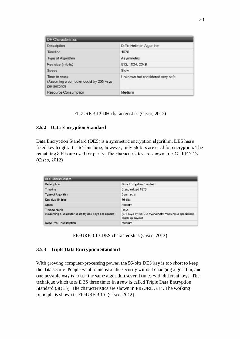
20
FIGURE 3.12 DH characteristics (Cisco, 2012)
3.5.2 Data Encryption Standard
Data Encryption Standard (DES) is a symmetric encryption algorithm. DES has a
fixed key length. It is 64-bits long, however, only 56-bits are used for encryption. The
remaining 8 bits are used for parity. The characteristics are shown in FIGURE 3.13.
(Cisco, 2012)
FIGURE 3.13 DES characteristics (Cisco, 2012)
3.5.3 Triple Data Encryption Standard
With growing computer-processing power, the 56-bits DES key is too short to keep
the data secure. People want to increase the security without changing algorithm, and
one possible way is to use the same algorithm several times with different keys. The
technique which uses DES three times in a row is called Triple Data Encryption
Standard (3DES). The characteristics are shown in FIGURE 3.14. The working
principle is shown in FIGURE 3.15. (Cisco, 2012)

21
FIGURE 3.14 3DES characteristics (Cisco, 2012)
FIGURE 3.15 3DES work principle (Cisco, 2012)
3.5.4 Advanced Encryption Standard
As time goes on, the computer-processing power becomes more and more powerful. It
means that 3DES will be broken someday in the future. Therefore, the U.S. National
Institute of Standards and Technology (NIST) invites the public to propose a new
standard to replace the DES and 3DES. This standard is called Advanced Encryption
Standard (AES). It took 5 years’ time to choose one algorithm from 15 different
options. On 2 October, 2000, NIST officially announced that Rijndael has been

22
chosen as Advanced Encryption Standard (AES).The one who wins is from two
Belgian cryptographers: Joan Daemen and Vincent Rijmen. Taking part of their two
names, the new standard is called Rijndael. (IAIK, 2013)
AES can operate over a variable-length block using variable-length keys. A 128-,
192-, or 256-bit key can be used to encrypt data blocks that are 128, 192, or 256 bits
long, and all nine combinations of key and block length are possible. The AES
algorithm has been analyzed extensively and is now used worldwide. Although it has
not been proven in day-to-day use to the degree that 3DES has, AES with the Rijndael
cipher is the more efficient algorithm. The characteristics are shown in FIGURE 3.16.
(Cisco, 2012)
FIGURE 3.16 AES characteristics (Cisco, 2012)
3.6 Type of IPsec VPN
Typically, there are two types of VPNs: site-to-site VPN and remote access VPN.
3.6.1 Site-to-site VPN
Site-to-site VPN is a connection using a VPN tunnel protocol to connect different
private networks. The VPN servers, which connect the two private networks, provide
a connection to a local private network. It is different from the remote access VPN
that connects one PC to a network. It connects the whole network. After the VPN
server establishes the VPN connection, the two terminal networks can access each
other just as local area network.
In a site-to-site VPN, hosts send and receive normal TCP/IP traffic through a VPN
gateway, which can be a router or a firewall. The VPN gateway is responsible for
encapsulating and encrypting outbound traffic from a particular site and sending it
through a VPN tunnel over the Internet to a peer VPN gateway at the target site. After
receiving the data, the peer VPN gateway strips the headers, decrypts the payload, and
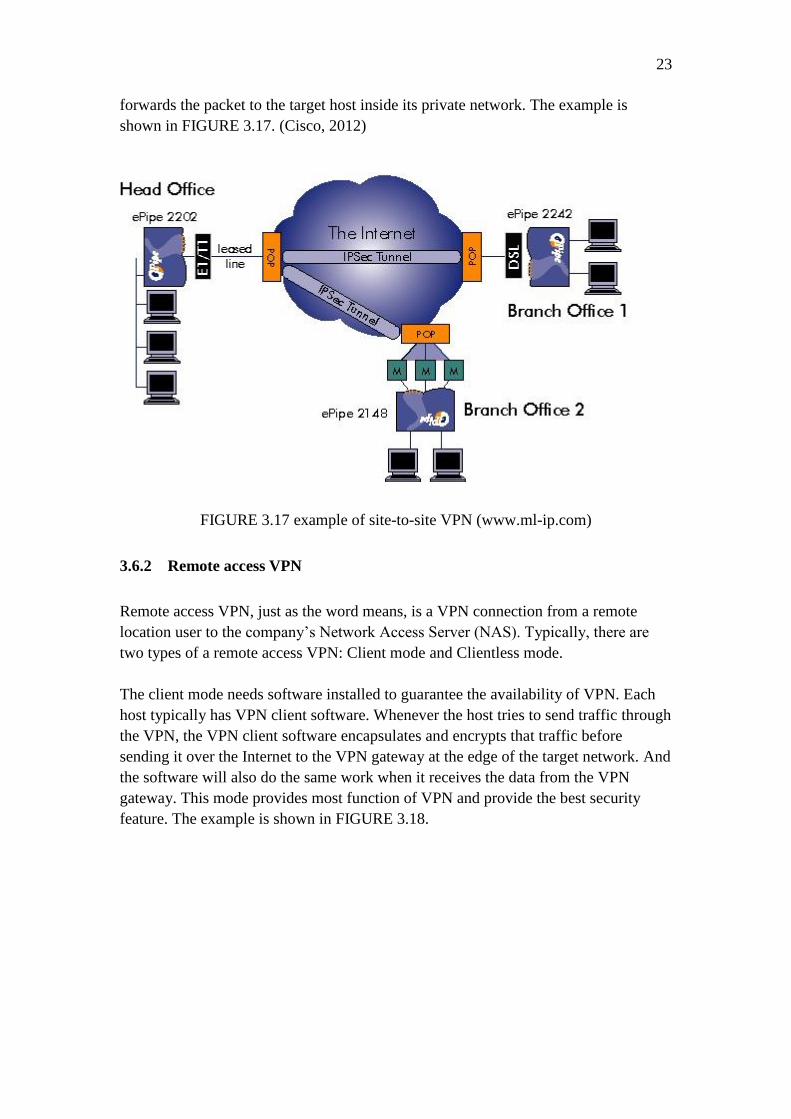
23
forwards the packet to the target host inside its private network. The example is
shown in FIGURE 3.17. (Cisco, 2012)
FIGURE 3.17 example of site-to-site VPN (www.ml-ip.com)
3.6.2 Remote access VPN
Remote access VPN, just as the word means, is a VPN connection from a remote
location user to the company’s Network Access Server (NAS). Typically, there are
two types of a remote access VPN: Client mode and Clientless mode.
The client mode needs software installed to guarantee the availability of VPN. Each
host typically has VPN client software. Whenever the host tries to send traffic through
the VPN, the VPN client software encapsulates and encrypts that traffic before
sending it over the Internet to the VPN gateway at the edge of the target network. And
the software will also do the same work when it receives the data from the VPN
gateway. This mode provides most function of VPN and provide the best security
feature. The example is shown in FIGURE 3.18.

24
FIGURE 3.18 Clientless VPN example (www.howstuffworks.com)
The clientless mode will use Secure Sockets Layer (SSL) protocol or Transport Layer
Security (TLS) protocol to guarantee the security without any additional software. It
is very easy to implement, but provide limited function. Nowadays, it is integrated in
common web browsers. It can reduce the firewalls workload and provide acceptable
security and performance.
SSL is a cryptographic system that uses two keys to encrypt data, a public key known
to everyone and a private or secret key known only to the recipient of the message.
The public key is published in a digital certificate, which also confirms the identity of
the web server.
4. DESIGN AND IMPLEMENTATION OF TEST VPN
After discussing so much theory of the VPN, in this chapter, we will discuss the
testing environment I use in my performance measurement. I will test the
performance between two routers, two firewalls, and two ASA firewalls.
The topology diagram is shown in FIGURE 4.1.

25
FIGURE 4.1 Basic topology diagram
The router I use is Cisco 2911, the firewall is Smoothwall express 3.0 SP3, and the
Cisco ASA firewall model is 5505. The links between devices will first normal link
then VPN tunnel.
The measurement software I use is Jperf. Jperf was developed by NLANR/DAST as a
modern alternative for measuring maximum TCP and UDP bandwidth performance.
Jperf allows the tuning of various parameters and UDP characteristics. Jperf reports
bandwidth, delay jitter, datagram loss. The graphic user interface is show as below in
FIGURE 4.2.
FIGURE 4.2 GUI of jperf

26
I change different parameter of transport layer to test their effect on performance. The
parameters are shown in FIGURE 4.3.
FIGURE 4.3 parameter of software
TCP windows size means the amount of data that a source can transmit before an
acknowledgement must be received. Window Size is a field in the TCP header that
enables the management of lost data and flow control. The max receive window size
is 65535 bytes. The segment size that will never be exceeded regardless of how large
the current window is called the maximum segment size (MSS). When deciding how
much data to put into a segment, each device in the TCP connection will choose the
amount based on the current window size, in conjunction with the various algorithms
described in the reliability section, but it will never be so large that the amount of data
exceeds the MSS of the device to which it is sending.
5. DESIGN IMPLEMENT AND MEASURE OF IPSEC VPN
5.1 Measurement between two Cisco 2911 routers
The topology diagram is shown in FIGURE 5.1 below.

27
FIGURE 5.1 Topology Diagram
The Routers are Cisco 2911, connected with crossover cable at interfaces
GigabitEthernet0/0. The two PCs are connected to interface GigabitEthernet0/1. The
operating system is Windows XP SP3, there are two NIC in these computers. The
maximum bandwidth of NIC is 100 Mbps.
I configure static route and no other security settings in the router so that the router
can use all the computing power to transfer the traffic. First, I test the TCP part of the
network, the buffer length is always 2 Mbytes, I only change the TCP window size
and Max Segment size. After I change one parameter, I test this setting for one minute,
and the result is show in the TABLE 5.1.
TABLE 5.1 the result of TCP
As we see from the TABLE 5.1, when the TCP window size is 16 Kbytes, the
outcome is very strange, it is about 18% lower than others. This is the first test, so
let’s see what will happen in next test.
Then, the UDP part, the buffer size is still 2 Mbytes, the packet size is change from 1
Kbyte to 63 Kbytes. Once I change the parameter, I test one minute, the result is
shown in TABLE 5.2.
TABLE 5.2 the result of UDP

28
From the TABLE 5.2, we can see that UDP is not a reliable link protocol, so the
bandwidth is not stable and either the jitter or packet lost rate.
I will use this as a baseline of other test, in the following tests. I will compare the data
I collect with this.
5.2 Measurement between two Cisco 2911 routers with VPN
In the second test, we will test the performance of normal link with VPN. The test
environment is the same as section 5.1. The topology diagram is shown in FIGURE
5.2.
FIGURE 5.2 second test topology
I configure the VPN with Cisco Configuration Professional (CCP), there are seven
steps by using the site-to-site VPN wizard. They are shown in FIGUREs 5.3 to 5.9.
FIGURE 5.3 First step

29
The reason why not chooses the quick setup is there are limited options for me to
choose, but the default setting is now what I need. So let’s choose step-by step here.
FIGURE 5.4 Second step
In this step we can define the remote peer’s address, which interface are using for
local tunneling, and the authentication method for authenticate each peer. From the
FIGURE 5.4, we can see the local tunneling interface is FastEthernet 0/0, the remote
address is 10.1.1.1, the authentication method is Pre-shared key.
30
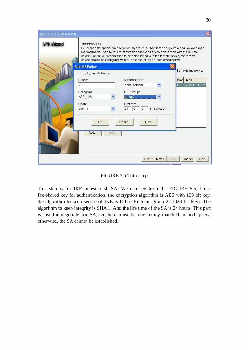
FIGURE 5.5 Third step
This step is for IKE to establish SA. We can see from the FIGURE 5.5, I use
Pre-shared key for authentication, the encryption algorithm is AES with 128 bit key,
the algorithm to keep secure of IKE is Diffie-Hellman group 2 (1024 bit key). The
algorithm to keep integrity is SHA 1. And the life time of the SA is 24 hours. This part
is just for negotiate for SA, so there must be one policy matched in both peers,
otherwise, the SA cannot be established.

31
FIGURE 5.6 Fifth step
This step is to define integrity and encryption algorithm for the packet in real traffic.
We can see that I use ESP protocol here, which means this is a tunnel mode VPN. The
encryption algorithm is AES with 128 bit key. The integrity algorithm is SHA with
HMAC. They are all the same as previous step, because if they are not match, the
tunnel cannot be established.

32
FIGURE 5.7 Sixth step
In this step, we define the local and remote network. This step is for router to decide
what kind of traffic should go to VPN tunnel, what are not. Only the traffic match
what we define here can go to VPN tunnel, other traffic will not go into VPN tunnel,
they will forward as the normal packet.

33
FIGURE 5.8 Seventh step
This step is for us to check the setting we have made before. If everything is right,
check the “Test VPN connectivity after configuring” checkbox, then click finish
button, the CCP will deliver your setting to the router and begin the test, the test
screenshot is shown in FIGURE 5.9, if you see the VPN is up, the configure process
is over; if not, the VPN is not up, the CCP will give you some possible reasons for
troubleshooting.

34
FIGURE 5.9 the VPN is up
First, I test the TCP part of the network, the buffer length is always 2 Mbytes, I only
change the TCP window size and Max Segment size. Once I change one parameter, I
test this setting for one minute, and the result is show in the TABLE 5.3.
TABLE 5.3 TCP outcome
We can see that the outcome shows that the VPN has a very poor performance, but it

35
should not be like this. Even the new header and authentication part cost more than
normal packet. When I check the router console interface, there is some text show in
the windows: “ERM-4-TX_BW_LIMIT: Maximum Tx Bandwidth limit of 85000
Kbps reached for Crypto functionality with securityk9 technology package license.”
The screenshot is show in FIGURE 5.10. So because of iOS’s limit, the outcome of
this test is a fact, but not used to compare to other outcome.
FIGURE 5.10 problem screenshot
Then, the UDP part, the buffer size is still 2 Mbytes, the packet size is change from 1
Kbyte to 63 Kbytes. Once I change the parameter, I test one minute, the result is
shown in TABLE 5.4.
TABLE 5.4 UDP outcome
We can see that the bandwidth is increasing when the packet size is increasing, so do
the jitter. The packet lost rate is also in a reasonable range.
5.3 Measurement between two Smoothwall firewall with VPN
In this part, we are going to test the performance between two Smoothwall with VPN.
The topology diagram is the same as before, just replace the router with Smooghwall.
The Smoothwall version is Smoothwall express 3.0 SP3, the two computers’

36
operating system are still Windows XP SP3. The Smoothwall is configured the
GREEN+RED mode, the RED ports connect the two Smoothwall together, and the
GREEN ports are for two PCs.
The VPN configuration is very simple in Smoothwall, just the local and remote IP
address and pre-share key. The configure page is shown in FIGURE 5.11 and 5.12.
FIGURE 5.11 Smoothwall’s configure page

37
FIGURE 5.11 VPN is open
If you want to see more details, it is shown in FIGURE 5.12. This is Smoothwall’s
VPN configuration I found in the Smoothwall file system (Smoothwall is a
Linux-based firewall). The Smoothwall’s VPN’s configuration is 3DES with MD5,
because it is not for customizing, this is not the same as other tests, but I can’t do any
help to this.

38
FIGURE 5.12 Smoothwall’s VPN configuration
First, I test the TCP part of the network, the buffer length is always 2 Mbytes, I only
change the TCP window size and Max Segment size. Once I change one parameter, I
test this setting for one minute, and the result is show in the TABLE 5.5.
TABLE 5.5 TCP outcome
From the table we can see that the bandwidth is about 3% lower than two routers
without anything. But when the TCP window size is 16 Kbytes, the outcome is still
very strange. So I test this set again, this time I open the task manager, use the
network utilization to monitor the whole process. The picture is shown in FIGURE
5.13.

39
FIGURE 5.13 16 Kbytes special test
From the screenshot, we can see that the network utilization is around 40%, so it is
not about the VPN or firewall, this is some bugs of the software.
Then, the UDP part, the buffer size is still 2 Mbytes, the packet size is change from 1
Kbyte to 63 Kbytes. Once I change the parameter, I test one minute, the result is
shown in TABLE 5.6.
TABLE 5.6 UDP outcome
Although UDP is an unreliable link protocol, I still wonder why it is such a low speed
when the packet size is 2 Kbytes. So I do all this test again, with task manager to
monitor the whole process, the result is shown in FIGURE 5.14.

40
FIGURE 5.14 UDP special test
From the picture we can see that only when the packet size is 1 Kbyte, the software
use all the bandwidth, others are not. I wonder if it is about the buffer size, I change
the buffer size to 100 Mbytes, do it again, the result is still the same, so I think this is
related to the software but not the devices.
5.4 Measurement between two Cisco 2811 routers with VPN
In this part, I am going to test the VPN performance between two Cisco 2811 routers,
because the Cisco 2911 routers have the license problem. We will see how the
Cisco2811 perform here. The topology diagram is the same as FIGURE 5.2. Just
replace the two routers with Cisco 2811.
I configure these two routers with CCP, so the process is the same as the FIGURE
show before and the parameter as well.
First, I test the TCP part of the network, the buffer length is always 2 Mbytes, I only
change the TCP window size and Max Segment size. Once I change one parameter, I
test this setting for one minute, and the result is show in the TABLE 5.7.

41
TABLE 5.7 TCP outcome
From the table, we can see that the performance is still very poor. There isn’t any text
come from the console interface this time. So I think the reason is relate to the
computing power of the router, they are older than the 2911 router.
Then, the UDP part, the buffer size is still 2 Mbytes, the packet size is change from 1
Kbyte to 63 Kbytes. Once I change the parameter, I test one minute, the result is
shown in TABLE 5.8.
TABLE 5.8 UDP outcome
This time, the old router even cannot finish the test. When the packet size comes to 8
Kbytes, the software becomes to loss connection, I cannot ping the default gateway. I
change cable, computers, try anything I can, but it still not works.
FIGURE 5.15 Troubleshooting

42
I open the network monitor, test again, from the network monitor, we can see that the
data is truly comes to the destination host, but I don’t know why the software not
work. There is some text from the software say that the datagram is out of order
sometimes, but the bandwidth is still 0 in software.
5.5 Measurement between two Cisco ASA 5505 firewalls
In this part, we are going to test how the performance between two Cisco ASA
firewall with VPN is. The topology diagram is the same as FIGURE 5.2, just replace
the two routers with two Cisco ASA firewall.
I configure the ASA firewall’s VPN with Cisco Adaptive Security Device Manager
(ASDM). The detail is shown in FIGURE 5.15 to 5.24.
FIGURE 5.15 step one
The first step is pretty simple, click Wizards, then point to VPN Wizards, after that, a
submenu comes out, then click Site-to-site VPN Wizards. After you click it, the new
window comes out, it is shown in FIGURE 5.16, there are just some introductions,
nothing else.

43
FIGURE 5.16 step two
FIGURE 5.17 step three

44
In this step, just define the remote peer’s address, because ASA is a firewall, so you
have to choose the port is inside or outside, we choose outside here.
FIGURE 5.18 step four
In this step, there are only two options, IKE v1 and IKE v2. There are some
differences between these two versions. For example, IKE v2 reduces bandwidth
requirements. IKEv2 supports EAP authentication. IKEv2 can detect whether a tunnel
is still alive.

45
FIGURE 5.19 step five
In this step, we define the local and remote network. We have talked about the
meaning before, it is used for deciding where the traffic should go. If the packet’s
address match the address here, it will go to the tunnel; if not, the packet will forward
as a normal packet.

46
FIGURE 5.20 step six
In this step, we will define the IKE authentication method. We will use pre-share key
here. We can see the difference between IKEv1 and IKEv2, it is not just believing the
key transmitted by the remote peer, it store a remote peer pre-share key in local
system to compare if the remote peer is the right one.

47
FIGURE 5.21 step seven
In this step, we will define the encryption and integrity method. The ASA firewall lists
all the algorithms here. Because we need a unified setting here, we choose
ESP-AES-SHA here.

48
FIGURE 5.22 step eight
In this step, it is mainly related to the advanced firewall settings. The first checkbox
means to ensure the traffic comes from the tunnel can bypass the firewall. The second
checkbox is to ensure your date is always in secure by adding additional
Diffle-Hallman key exchange. It will exchange the key in each session no matter if the
tunnel is in SA lifetime. The third checkbox is about the Network Address Translation
(NAT). Because if you are not sure about whether the remote peer support NAT in this
session, you’d better check this one to ensure the VPN can work.

49
FIGURE 5.23 step nine
This step is for you to check your configuration. If everything is right, just click the
finish button, the software will deliver the setting to the ASA firewall; if not, you can
click back button to modify them. After I check all the setting, they are right, finish
the wizard. Test whether the tunnel is up, the result is shown in FIGURE 5.24.
FIGURE 5.24 success

50
First, I test the TCP part of the network, the buffer length is always 2 Mbytes, I only
change the TCP window size and Max Segment size. Once I change one parameter, I
test this setting for one minute, and the result is show in the TABLE 5.9.
TABLE 5.9 TCP outcome
From the table we can see that this is the best performance of Cisco device. When the
TCP window size is 16 Kbytes, the problem we have already discussed before, this is
related to the software, this time I try to use parallel stream option, when it is 3
parallel streams, the bandwidth can up to 70378 Kbits/sec.
Then, the UDP part, the buffer size is still 2 Mbytes, the packet size is change from 1
Kbyte to 63 Kbytes. Once I change the parameter, I test one minute, the result is
shown in TABLE 5.10.
TABLE 5.10 UDP outcome
From the table, we can found that the same situation comes again, when the UDP
packet size comes to 32 Kbytes, I become to loss connection. So I do the test again,
open the network monitor at the same time, but no traffic comes to the destination
host this time, the traffic must be stopped by ASA firewall. The screenshot is shown in
FIGURE 5.25.

51
FIGURE 5.25 troubleshooting
6. CONCLUSION
After talking so much, we know the history of Internet, the history of VPN, and then
we test the performance of IPsec VPN. Although there are some problems in the test, I
try my best to give a good answer. Now it’s time for me to give a conclusion.
First to say is hardware. I test the Cisco 2911, 2811, and ASA 5505firewall. Cisco
2911 is the latest Integrated Services Router, it should support the most advanced
technology and have the best performance, however, because of the license problem,
the performance is very poor. So let’s see some official document from the Cisco.
Based on the Cisco white paper, the IPsec Maximum performance of Cisco 2911 is
170 Mbps and it can support 225 tunnels working in the same time. Second is the
Cisco 2811 router, it is an old device. Based on the Cisco official document, the
maximum AES throughput is 55 Mbps. From my test, the average bandwidth is 34.8
Mbps, there are about 36.7% less than the official document. This is not a reasonable
arrange. I think it is because the router is used everyday, the device is aging seriously.
The last one is ASA 5505 firewall, the official document shows the maximum VPN
throughout is 100 Mbps, my test result is 82.4 Mbps. It is 17.6% less than official
document. This is a reasonable arrange if we exclude error and IPsec additional
header and authentication part.
Second to say is software. Smoothwall is a Linux-based firewall, it use the PC
hardware, so it is a powerful and free firewall. Although it only supports the 3DES
encryption method, it has a good performance. Then is the measurement software
Jperf. It is really an old software, last update time is 2010. There are some bugs and
not very stable either, but all in all, it is a good free software to measure the network

52
performance.
At last, I also find some solutions to improve the performance of Cisco devices. The
solution is Cisco VPN Internal Service Module (VPN ISM). It provides the capability
to increase performance for VPN. The module has a multicore processor that works
individually. It helps to ensure maximum concurrent encrypted application
performance and release the router’s CPU power to maintain performance for other
services. With this module, Cisco 2911 routers can provide 150 to 600 Mbps IPsec
encryption service. The drawback is the module only supports the new device, but if
you really want to have a good performance, I don’t recommend choosing the old
device, because they have a lot of limits and not support for the latest technology.
VPN is a good solution for modern network security. It provides good security with
little resource and money, also easy to implement and maintain. When you are
choosing the VPN hardware, you can consider choosing the ASA 5505 firewall or
Smoothwall if you have limited money and want to have advanced security features.
If you have a high work load, want to upgrade your device real time and also want to
have route function and advanced security feature, Cisco 2911 or higher serials would
be a good choice.
7 BIBLIOGRAPHY
Chen, L., 2011. Analysis of multi-protocol label switching technology. Fujian
Computer.
Cisco, 2008. CCNA Exploration, s.l.: s.n.
Cisco, 2012. CCNA Security 1.1. s.l.:s.n.
David, L. C., 1999. IT Manager's Guide to Virtual Private Networks. s.l.:s.n.
Encyclopedia, T. N., 2006. Frame Relay. [Online]
Available at: http://www.thenetworkencyclopedia.com/d2.asp?ref=798
Hanks, L. F. &. T., 1994. Generic Routing Encapsulation (GRE). [Online]
Available at: http://www.rfc-editor.org/rfc/rfc1701.txt
He, B., 2002. IP Virtual Private Network. s.l.:s.n.
IAIK, 2013. AES Lounge. [Online]
Available at: http://www.iaik.tugraz.at/content/research/krypto/aes/
Sina, 2007. OSI network model and TCP/IP network model. [Online]
Available at: http://tech.sina.com.cn/roll/2007-06-24/2315345519.shtml
53
Singh, G. & Singh, J., 2011. Performance Evaluation and Optimization of TCP
Parameters over Frame Relay Network. International Journal on Computer Science
and Engineering.
Softhouse, 2013. Development history of Internet. [Online]
Available at: http://www.softhouse.com.cn/news/show/4324.html
Sosinsky, B., 2009. Networking Bible. s.l.:s.n.
Stephen, K. & Randall, A., 1998. IP Authentication Header. [Online]
Available at: http://www.rfc-editor.org/rfc/rfc2402.txt
Wang, B., 2011. Multi-protocol Label Switching and Application. Computer
Knowledge and Technology.
Wang, R., 2005. Principle and implementation of the Generic Routing Encapsulation.
Netinfo Security, p. 61.
Yang, X., 2005. Web design and production tutorials.
Yang, X., 2010. Diffie-Hellman key exchange algorithm and its optimization. [Online]
Available at: http://wenku.baidu.com/view/8000bcd049649b6648d74780.html
Zeng, J., 2012. Improved Tunnel-routing Method for Honeyd. Computer Engineering.
Zhou, Q., Xiao, D. & Tang, Y., 2005. VPN's Security Gateway Design and
Implementation based on Linux and IPSec. Application Research of Computers, pp.
229-234.
8. APPENDIX
Chapter 5.1, two routers’ running configuration:
R1’s configuration:
Current configuration : 1380 bytes
!
! Last configuration change at 11:33:08 UTC Sun Apr 28 2013
version 15.2
service timestamps debug datetime msec
service timestamps log datetime msec

54
no service password-encryption
!
hostname R1
!
boot-start-marker
boot-end-marker
!
!
!
no aaa new-model
!
!
no ipv6 cef
ip auth-proxy max-login-attempts 5
ip admission max-login-attempts 5
!
!
!
!
!
ip cef
!
multilink bundle-name authenticated
!
!
!
!
license udi pid CISCO2911/K9 sn FCZ153720T5
!
!
!
redundancy
!
!
!
!
!
!
!
!
!
!
!
!

55
!
!
interface Embedded-Service-Engine0/0
no ip address
shutdown
!
interface GigabitEthernet0/0
ip address 10.1.1.1 255.255.255.252
duplex auto
speed auto
!
interface GigabitEthernet0/1
ip address 192.168.1.1 255.255.255.0
duplex auto
speed auto
!
interface GigabitEthernet0/2
no ip address
shutdown
duplex auto
speed auto
!
interface Serial0/0/0
no ip address
shutdown
clock rate 2000000
!
interface Serial0/0/1
no ip address
shutdown
clock rate 2000000
!
ip forward-protocol nd
!
no ip http server
no ip http secure-server
!
ip route 192.168.2.0 255.255.255.0 GigabitEthernet0/0
!
!
!
!
control-plane
!

56
!
!
line con 0
line aux 0
line 2
no activation-character
no exec
transport preferred none
transport input all
transport output pad telnet rlogin lapb-ta mop udptn v120 ssh
stopbits 1
line vty 0 4
login
transport input all
!
scheduler allocate 20000 1000
!
end
R2’s configuration:
Current configuration : 1379 bytes
!
! Last configuration change at 07:17:28 UTC Fri May 8 2009
version 15.2
service timestamps debug datetime msec
service timestamps log datetime msec
no service password-encryption
!
hostname R2
!
boot-start-marker
boot-end-marker
!
!
!
no aaa new-model
!
!
no ipv6 cef
ip auth-proxy max-login-attempts 5
ip admission max-login-attempts 5
!
!

57
!
!
!
ip cef
!
multilink bundle-name authenticated
!
!
!
!
license udi pid CISCO2911/K9 sn FCZ153720TH
!
!
!
redundancy
!
!
!
!
!
!
!
!
!
!
!
!
!
!
interface Embedded-Service-Engine0/0
no ip address
shutdown
!
interface GigabitEthernet0/0
ip address 10.1.1.2 255.255.255.252
duplex auto
speed auto
!
interface GigabitEthernet0/1
ip address 192.168.2.1 255.255.255.0
duplex auto
speed auto
!
interface GigabitEthernet0/2

58
no ip address
shutdown
duplex auto
speed auto
!
interface Serial0/0/0
no ip address
shutdown
clock rate 2000000
!
interface Serial0/0/1
no ip address
shutdown
clock rate 2000000
!
ip forward-protocol nd
!
no ip http server
no ip http secure-server
!
ip route 192.168.1.0 255.255.255.0 GigabitEthernet0/0
!
!
!
!
control-plane
!
!
!
line con 0
line aux 0
line 2
no activation-character
no exec
transport preferred none
transport input all
transport output pad telnet rlogin lapb-ta mop udptn v120 ssh
stopbits 1
line vty 0 4
login
transport input all
!
scheduler allocate 20000 1000
!

59
end
Chapter 5.2, two routers’ running configuration:
R1’s configuration:
Current configuration : 3560 bytes
!
! Last configuration change at 12:31:59 UTC Tue Apr 30 2013
version 15.2
service timestamps debug datetime msec
service timestamps log datetime msec
no service password-encryption
!
hostname R1
!
boot-start-marker
boot-end-marker
!
!
no logging buffered
!
no aaa new-model
!
!
no ipv6 cef
ip auth-proxy max-login-attempts 5
ip admission max-login-attempts 5
!
!
!
!
!
ip cef
!
multilink bundle-name authenticated
!
!
!
crypto pki trustpoint TP-self-signed-1415673417
enrollment selfsigned
subject-name cn=IOS-Self-Signed-Certificate-1415673417
revocation-check none
rsakeypair TP-self-signed-1415673417

60
!
!
crypto pki certificate chain TP-self-signed-1415673417
certificate self-signed 01
3082022B 30820194 A0030201 02020101 300D0609 2A864886 F70D0101
05050030
31312F30 2D060355 04031326 494F532D 53656C66 2D536967 6E65642D
43657274
69666963 6174652D 31343135 36373334 3137301E 170D3133 30343330
31323038
31305A17 0D323030 31303130 30303030 305A3031 312F302D 06035504
03132649
4F532D53 656C662D 5369676E 65642D43 65727469 66696361 74652D31
34313536
37333431 3730819F 300D0609 2A864886 F70D0101 01050003 818D0030
81890281
8100A2D8 A2E0BED7 95171ABA 8C1BF77C 1E71AE8F D43A4FBA
CB1BBDF6 903B9509
805F4104 3B5D6CE4 F1E3FF24 9FD52892 C9BD2DDD BF99B552 B78B7433
EFF0FA3F
71C7A9B3 6F402413 65EF5E82 150C12B7 092770A4 269AC59B F58547F2
7D736595
9F031E56 DCC4F519 DF132CF6 08A0CA9B 3401E344 49C694AA 1EAD9611
744CD1D3
935F0203 010001A3 53305130 0F060355 1D130101 FF040530 030101FF
301F0603
551D2304 18301680 14CB97CA 33F9371D B769AEE9 605B6831 7FC9DE2E
58301D06
03551D0E 04160414 CB97CA33 F9371DB7 69AEE960 5B68317F C9DE2E58
300D0609
2A864886 F70D0101 05050003 81810070 A80FF343 7B6FE3E3 9C3509F1
2075157A
9A235D30 16C42363 2688EC10 2B18F341 2256845B 8EC9126E 3A3CFEF9
E2BE18B1
643B17DF 38CB25C2 3D6CD2B5 F3756B02 9871DD8A A64A1B4A 0EF71F0B
5AA44513
D3861FAE 972A2D4D 4CA589EB 6857A475 0DA58178 79BEC86D F0470E4C
FEAB27EB
42658E28 24AD0C70 57068745 47CFDF
quit
license udi pid CISCO2911/K9 sn FCZ153720T5
!
!
username admin privilege 15 secret 5 $1$.5cH$VMu8M8LDOOo5u38o7LDoQ0

61
!
redundancy
!
!
!
!
!
!
!
crypto isakmp policy 2
encr aes
authentication pre-share
group 2
crypto isakmp key 1234abcd address 10.1.1.2
!
!
crypto ipsec transform-set 1 esp-aes esp-sha-hmac
!
!
!
crypto map SDM_CMAP_1 1 ipsec-isakmp
description Tunnel to10.1.1.2
set peer 10.1.1.2
set transform-set 1
match address 100
!
!
!
!
!
interface Embedded-Service-Engine0/0
no ip address
shutdown
!
interface GigabitEthernet0/0
ip address 10.1.1.1 255.255.255.252
duplex auto
speed auto
crypto map SDM_CMAP_1
!
interface GigabitEthernet0/1
ip address 192.168.1.1 255.255.255.0
duplex auto
speed auto

62
!
interface GigabitEthernet0/2
no ip address
shutdown
duplex auto
speed auto
!
interface Serial0/0/0
no ip address
shutdown
clock rate 2000000
!
interface Serial0/0/1
no ip address
shutdown
clock rate 2000000
!
ip forward-protocol nd
!
no ip http server
ip http authentication local
ip http secure-server
!
ip route 192.168.2.0 255.255.255.0 GigabitEthernet0/0
!
access-list 100 remark CCP_ACL Category=4
access-list 100 remark IPSec Rule
access-list 100 permit ip 192.168.1.0 0.0.0.255 192.168.2.0 0.0.0.255
!
!
!
control-plane
!
!
!
line con 0
line aux 0
line 2
no activation-character
no exec
transport preferred none
transport input all
transport output pad telnet rlogin lapb-ta mop udptn v120 ssh
stopbits 1
63
line vty 0 4
login
transport input all
!
scheduler allocate 20000 1000
!
end
R2’s configuration:
Current configuration : 3540 bytes
!
! Last configuration change at 08:14:45 UTC Sun May 10 2009
version 15.2
service timestamps debug datetime msec
service timestamps log datetime msec
no service password-encryption
!
hostname R2
!
boot-start-marker
boot-end-marker
!
!
!
no aaa new-model
!
!
no ipv6 cef
ip auth-proxy max-login-attempts 5
ip admission max-login-attempts 5
!
!
!
!
!
ip cef
!
multilink bundle-name authenticated
!
!
!
crypto pki trustpoint TP-self-signed-4228095981
enrollment selfsigned

64
subject-name cn=IOS-Self-Signed-Certificate-4228095981
revocation-check none
rsakeypair TP-self-signed-4228095981
!
!
crypto pki certificate chain TP-self-signed-4228095981
certificate self-signed 01
3082022B 30820194 A0030201 02020101 300D0609 2A864886 F70D0101
05050030
31312F30 2D060355 04031326 494F532D 53656C66 2D536967 6E65642D
43657274
69666963 6174652D 34323238 30393539 3831301E 170D3039 30353130
30373532
31375A17 0D323030 31303130 30303030 305A3031 312F302D 06035504
03132649
4F532D53 656C662D 5369676E 65642D43 65727469 66696361 74652D34
32323830
39353938 3130819F 300D0609 2A864886 F70D0101 01050003 818D0030
81890281
8100C7FC C22FEE57 769F553D EFA58EC0 28FDA40F 9057D177 698C3605
69DF75CB
8CE7671D 341BBD56 BE2A264A AB90C74A 96548440 7DF03C2E 328DD982
0FC4D832
E4598713 76680D6A CCA100BB DA98A628 42E63057 C441C403 FA46D0B8
F86E8C50
DFAAA193 E18FF977 4E77A92F F953C3AD F88123E8 6B0E8F98 FFD8DA6E
265DD8C3
3E030203 010001A3 53305130 0F060355 1D130101 FF040530 030101FF
301F0603
551D2304 18301680 14E20678 96A8E4D3 7EE778BF 183ACAD6 917A4ECC
A9301D06
03551D0E 04160414 E2067896 A8E4D37E E778BF18 3ACAD691 7A4ECCA9
300D0609
2A864886 F70D0101 05050003 81810052 7CB59C5A 266778AE CD7B7F74
192054D2
5D4168E8 9941A735 617BE2BF 689C170B D115B2E9 D4C06358 55EEB4B2
AF1130BE
26D71F67 30452802 4ED015D5 89B5E8B5 3A317E41 A44D0530 7CE9A01B
1E3D09E7
3C644DA2 56A8E78D 63388086 5D222A2B 5D4DDE3A 5CD74F84 57EE093E
DF11B079
57340F36 EBC09672 E98CCF40 EDA2CE
quit
license udi pid CISCO2911/K9 sn FCZ153720TH

65
!
!
username admin privilege 15 secret 5 $1$e0AN$ahepvhZscQ4zbTXQv.BjB1
!
redundancy
!
!
!
!
!
!
!
crypto isakmp policy 2
encr aes
authentication pre-share
group 2
crypto isakmp key 1234abcd address 10.1.1.1
!
!
crypto ipsec transform-set 1 esp-aes esp-sha-hmac
!
!
!
crypto map SDM_CMAP_1 1 ipsec-isakmp
description Tunnel to10.1.1.1
set peer 10.1.1.1
set transform-set 1
match address 100
!
!
!
!
!
interface Embedded-Service-Engine0/0
no ip address
shutdown
!
interface GigabitEthernet0/0
ip address 10.1.1.2 255.255.255.252
duplex auto
speed auto
crypto map SDM_CMAP_1
!
interface GigabitEthernet0/1
66
ip address 192.168.2.1 255.255.255.0
duplex auto
speed auto
!
interface GigabitEthernet0/2
no ip address
shutdown
duplex auto
speed auto
!
interface Serial0/0/0
no ip address
shutdown
clock rate 2000000
!
interface Serial0/0/1
no ip address
shutdown
clock rate 2000000
!
ip forward-protocol nd
!
no ip http server
ip http authentication local
ip http secure-server
!
ip route 192.168.1.0 255.255.255.0 GigabitEthernet0/0
!
access-list 100 remark CCP_ACL Category=4
access-list 100 remark IPSec Rule
access-list 100 permit ip 192.168.2.0 0.0.0.255 192.168.1.0 0.0.0.255
!
!
!
control-plane
!
!
!
line con 0
line aux 0
line 2
no activation-character
no exec
transport preferred none

67
transport input all
transport output pad telnet rlogin lapb-ta mop udptn v120 ssh
stopbits 1
line vty 0 4
login
transport input all
!
scheduler allocate 20000 1000
!
end
Chapter 5.4, two routers’ running configuration:
R1’s configuration
Current configuration : 3149 bytes
!
version 12.4
service timestamps debug datetime msec
service timestamps log datetime msec
no service password-encryption
!
hostname R1
!
boot-start-marker
boot-end-marker
!
no logging buffered
!
no aaa new-model
!
crypto pki trustpoint TP-self-signed-3772933778
enrollment selfsigned
subject-name cn=IOS-Self-Signed-Certificate-3772933778
revocation-check none
rsakeypair TP-self-signed-3772933778
!
!
crypto pki certificate chain TP-self-signed-3772933778
certificate self-signed 01
3082023A 308201A3 A0030201 02020101 300D0609 2A864886 F70D0101
04050030
31312F30 2D060355 04031326 494F532D 53656C66 2D536967 6E65642D
43657274

68
69666963 6174652D 33373732 39333337 3738301E 170D3133 30353034
30383539
33355A17 0D323030 31303130 30303030 305A3031 312F302D 06035504
03132649
4F532D53 656C662D 5369676E 65642D43 65727469 66696361 74652D33
37373239
33333737 3830819F 300D0609 2A864886 F70D0101 01050003 818D0030
81890281
8100A09B 2DEB6122 53B32D30 967E8CC8 C1A64B7D 797E1A62 8C831FFF
683BE3C0
FFF2A260 C3694990 DFE284D1 920B12FC 86CB0DCB 43765457 7B7F050C
B33BAA56
0CF12265 C108AAD3 1F2F71C8 BF76CE56 F07645FE 93CFDD4F 3874CDAC
4E47CFAD
A1107B47 0C4E578C EA218C07 C241F00C A44CAF5F B1AAE23C AECEB923
76171FE6
93650203 010001A3 62306030 0F060355 1D130101 FF040530 030101FF
300D0603
551D1104 06300482 02523130 1F060355 1D230418 30168014 BDEDC322
A4D29FE0
875143D5 2D6C208A D29DBFE2 301D0603 551D0E04 160414BD EDC322A4
D29FE087
5143D52D 6C208AD2 9DBFE230 0D06092A 864886F7 0D010104 05000381
81004115
CE8A2290 C2E3074E 6BFF80E9 C4DB9615 AFA7C9A2 E8CA69C0 CC88521E
8511709B
67E4791A 3E8AC248 3586677D 4D5FC0F2 A97ED52B 79348EC3 07B1B6A7
F3B5B8BF
EDF27324 43B6F8AD 212728F3 B2A65A59 0C533B7F 8E2007BF 1BD917D1
A5D10EE8
0B47ECBB F69BDFE7 D78A1910 4449334A E064FFEF 07938F71 9D3E2F01
F0F0
quit
dot11 syslog
!
!
ip cef
!
!
!
multilink bundle-name authenticated
!
!
voice-card 0
69
no dspfarm
!
!
!
!
!
!
!
!
!
!
!
!
!
!
!
!
!
!
username admin privilege 15 secret 5 $1$U12m$jIzpBBvWRY/zGU1SplPa81
!
!
crypto isakmp policy 2
encr aes
authentication pre-share
group 2
crypto isakmp key 1234abcd address 10.1.1.2
!
!
crypto ipsec transform-set 1 esp-aes esp-sha-hmac
!
crypto map SDM_CMAP_1 1 ipsec-isakmp
description Tunnel to10.1.1.2
set peer 10.1.1.2
set transform-set 1
match address 100
!
archive
log config
hidekeys
!
!
!
!

70
!
!
interface FastEthernet0/0
ip address 10.1.1.1 255.255.255.252
duplex auto
speed auto
crypto map SDM_CMAP_1
!
interface FastEthernet0/1
ip address 192.168.1.1 255.255.255.0
duplex auto
speed auto
!
interface Serial0/0/0
no ip address
shutdown
clock rate 125000
!
interface Serial0/0/1
no ip address
shutdown
clock rate 125000
!
ip forward-protocol nd
ip route 192.168.2.0 255.255.255.0 FastEthernet0/0
!
!
ip http server
ip http authentication local
ip http secure-server
!
access-list 100 remark CCP_ACL Category=4
access-list 100 remark IPSec Rule
access-list 100 permit ip 192.168.1.0 0.0.0.255 192.168.2.0 0.0.0.255
!
!
!
!
!
!
control-plane
!
!
!

71
!
!
!
!
!
!
!
line con 0
line aux 0
line vty 0 4
login
!
scheduler allocate 20000 1000
!
end
R2’s configuration
Current configuration : 3149 bytes
!
version 12.4
service timestamps debug datetime msec
service timestamps log datetime msec
no service password-encryption
!
hostname R2
!
boot-start-marker
boot-end-marker
!
no logging buffered
!
no aaa new-model
dot11 syslog
!
!
ip cef
!
!
!
multilink bundle-name authenticated
!
!
voice-card 0

72
no dspfarm
!
!
!
!
!
!
!
!
!
!
!
!
!
!
!
!
!
crypto pki trustpoint TP-self-signed-1480346653
enrollment selfsigned
subject-name cn=IOS-Self-Signed-Certificate-1480346653
revocation-check none
rsakeypair TP-self-signed-1480346653
!
!
crypto pki certificate chain TP-self-signed-1480346653
certificate self-signed 01
3082023A 308201A3 A0030201 02020101 300D0609 2A864886 F70D0101
04050030
31312F30 2D060355 04031326 494F532D 53656C66 2D536967 6E65642D
43657274
69666963 6174652D 31343830 33343636 3533301E 170D3133 30353034
31353430
35365A17 0D323030 31303130 30303030 305A3031 312F302D 06035504
03132649
4F532D53 656C662D 5369676E 65642D43 65727469 66696361 74652D31
34383033
34363635 3330819F 300D0609 2A864886 F70D0101 01050003 818D0030
81890281
8100F998 9F258DC7 1E903946 8D1B6EC6 07F923DD 65B1EF51 55171705
2D5513E3
9FA5AB24 F1547031 91590C16 3CCFAE44 02CBD99A C2B2A6EB 19D23EDF
35C9C09F
5B87CBBC A7CBB21A FB85FF54 910B606E 67B91FE5 F766C337 08DA0A4F

73
F511F533
EACCBCF4 F6EA3618 30D1F2B0 526173B1 83B976F5 8E48950A ABEF2F39
D592EEBC
6F070203 010001A3 62306030 0F060355 1D130101 FF040530 030101FF
300D0603
551D1104 06300482 02523230 1F060355 1D230418 30168014 DE56D5C6
0728899D
B50035E6 4803C0D4 1CBF290B 301D0603 551D0E04 160414DE 56D5C607
28899DB5
0035E648 03C0D41C BF290B30 0D06092A 864886F7 0D010104 05000381
810092F7
B655D9EC 41D9F17F 4041E679 67DF56DF 4C597C38 EC54B2AE 08588FC4
E4488326
4FEA6DF4 D882B3B2 88B4E4AF 1E8CA079 A4349C03 C8C7C10D 2A2C316D
0E2D4FFB
DF5E2BFB C655208F 820569BD 18321B52 A70FC20A FEA2BBD3 8C7C07CB
648C4FA8
D965933A 04A67749 3828914B F7E0EA01 ACE8351A EFDFDE91 B6E35F38
AC1E
quit
!
!
username admin privilege 15 secret 5 $1$9.Wp$b.sldp03MoR72bLNKYkg4/
archive
log config
hidekeys
!
!
crypto isakmp policy 2
encr aes
authentication pre-share
group 2
crypto isakmp key 1234abcd address 10.1.1.1
!
!
crypto ipsec transform-set 1 esp-aes esp-sha-hmac
!
crypto map SDM_CMAP_1 1 ipsec-isakmp
description Tunnel to10.1.1.1
set peer 10.1.1.1
set transform-set 1
match address 100
!
!

74
!
!
!
!
!
interface FastEthernet0/0
ip address 10.1.1.2 255.255.255.252
duplex auto
speed auto
crypto map SDM_CMAP_1
!
interface FastEthernet0/1
ip address 192.168.2.1 255.255.255.0
duplex auto
speed auto
!
interface Serial0/0/0
no ip address
shutdown
clock rate 125000
!
interface Serial0/0/1
no ip address
shutdown
clock rate 125000
!
ip forward-protocol nd
ip route 192.168.1.0 255.255.255.0 FastEthernet0/0
!
!
ip http server
ip http authentication local
ip http secure-server
!
access-list 100 remark CCP_ACL Category=4
access-list 100 remark IPSec Rule
access-list 100 permit ip 192.168.2.0 0.0.0.255 192.168.1.0 0.0.0.255
!
!
!
!
!
!
control-plane

75
!
!
!
!
!
!
!
!
!
!
line con 0
line aux 0
line vty 0 4
login
!
scheduler allocate 20000 1000
!
end
Chapter 5.5, two firewalls’ running configuration:
ASA1’s configuration
ASA Version 8.4(3)
!
hostname ASA1
enable password 8Ry2YjIyt7RRXU24 encrypted
passwd 2KFQnbNIdI.2KYOU encrypted
names
!
interface Ethernet0/0
switchport access vlan 2
!
interface Ethernet0/1
!
interface Ethernet0/2
!
interface Ethernet0/3
!
interface Ethernet0/4
!
interface Ethernet0/5
!
interface Ethernet0/6

76
!
interface Ethernet0/7
!
interface Vlan1
nameif inside
security-level 100
ip address 192.168.1.1 255.255.255.0
!
interface Vlan2
nameif outside
security-level 0
ip address 10.1.1.1 255.255.255.252
!
ftp mode passive
object network obj_any
subnet 0.0.0.0 0.0.0.0
object network NETWORK_OBJ_192.168.1.0_24
subnet 192.168.1.0 255.255.255.0
object network NETWORK_OBJ_192.168.2.0_24
subnet 192.168.2.0 255.255.255.0
object network asa2
host 10.1.1.2
object network local
subnet 192.168.1.0 255.255.255.0
object network remote
subnet 192.168.2.0 255.255.255.0
access-list outside_cryptomap extended permit ip object local object remote
pager lines 24
logging asdm informational
mtu inside 1500
mtu outside 1500
icmp unreachable rate-limit 1 burst-size 1
no asdm history enable
arp timeout 14400
nat (inside,outside) source static NETWORK_OBJ_192.168.1.0_24
NETWORK_OBJ_192.168.1.0_24 destination static
NETWORK_OBJ_192.168.2.0_24 NETWORK_OBJ_192.168.2.0_24 no-proxy-arp
route-lookup
nat (inside,outside) source static local local destination static remote remote
no-proxy-arp route-lookup
!
object network obj_any
nat (inside,outside) dynamic interface
route outside 192.168.2.0 255.255.255.0 10.1.1.2 1

77
timeout xlate 3:00:00
timeout pat-xlate 0:00:30
timeout conn 1:00:00 half-closed 0:10:00 udp 0:02:00 icmp 0:00:02
timeout sunrpc 0:10:00 h323 0:05:00 h225 1:00:00 mgcp 0:05:00 mgcp-pat 0:05:00
timeout sip 0:30:00 sip_media 0:02:00 sip-invite 0:03:00 sip-disconnect 0:02:00
timeout sip-provisional-media 0:02:00 uauth 0:05:00 absolute
timeout tcp-proxy-reassembly 0:01:00
timeout floating-conn 0:00:00
dynamic-access-policy-record DfltAccessPolicy
user-identity default-domain LOCAL
http server enable
http 192.168.1.0 255.255.255.0 inside
no snmp-server location
no snmp-server contact
snmp-server enable traps snmp authentication linkup linkdown coldstart warmstart
crypto ipsec ikev1 transform-set ESP-AES-128-SHA esp-aes esp-sha-hmac
crypto ipsec ikev1 transform-set ESP-AES-128-MD5 esp-aes esp-md5-hmac
crypto ipsec ikev1 transform-set ESP-AES-192-SHA esp-aes-192 esp-sha-hmac
crypto ipsec ikev1 transform-set ESP-AES-192-MD5 esp-aes-192 esp-md5-hmac
crypto ipsec ikev1 transform-set ESP-AES-256-SHA esp-aes-256 esp-sha-hmac
crypto ipsec ikev1 transform-set ESP-AES-256-MD5 esp-aes-256 esp-md5-hmac
crypto ipsec ikev1 transform-set ESP-3DES-SHA esp-3des esp-sha-hmac
crypto ipsec ikev1 transform-set ESP-3DES-MD5 esp-3des esp-md5-hmac
crypto ipsec ikev1 transform-set ESP-DES-SHA esp-des esp-sha-hmac
crypto ipsec ikev1 transform-set ESP-DES-MD5 esp-des esp-md5-hmac
crypto ipsec ikev2 ipsec-proposal DES
protocol esp encryption des
protocol esp integrity sha-1 md5
crypto ipsec ikev2 ipsec-proposal 3DES
protocol esp encryption 3des
protocol esp integrity sha-1 md5
crypto ipsec ikev2 ipsec-proposal AES
protocol esp encryption aes
protocol esp integrity sha-1 md5
crypto ipsec ikev2 ipsec-proposal AES192
protocol esp encryption aes-192
protocol esp integrity sha-1 md5
crypto ipsec ikev2 ipsec-proposal AES256
protocol esp encryption aes-256
protocol esp integrity sha-1 md5
crypto map outside_map 1 match address outside_cryptomap
crypto map outside_map 1 set pfs
crypto map outside_map 1 set peer 10.1.1.2
crypto map outside_map 1 set ikev1 transform-set ESP-AES-128-SHA

78
crypto map outside_map 1 set ikev2 ipsec-proposal AES
crypto map outside_map interface outside
crypto ikev2 policy 1
encryption aes-256
integrity sha
group 5 2
prf sha
lifetime seconds 86400
crypto ikev2 policy 10
encryption aes-192
integrity sha
group 5 2
prf sha
lifetime seconds 86400
crypto ikev2 policy 20
encryption aes
integrity sha
group 5 2
prf sha
lifetime seconds 86400
crypto ikev2 policy 30
encryption 3des
integrity sha
group 5 2
prf sha
lifetime seconds 86400
crypto ikev2 policy 40
encryption des
integrity sha
group 5 2
prf sha
lifetime seconds 86400
crypto ikev2 enable outside
crypto ikev1 enable outside
crypto ikev1 policy 10
authentication crack
encryption aes-256
hash sha
group 2
lifetime 86400
crypto ikev1 policy 20
authentication rsa-sig
encryption aes-256
hash sha

79
group 2
lifetime 86400
crypto ikev1 policy 30
authentication pre-share
encryption aes-256
hash sha
group 2
lifetime 86400
crypto ikev1 policy 40
authentication crack
encryption aes-192
hash sha
group 2
lifetime 86400
crypto ikev1 policy 50
authentication rsa-sig
encryption aes-192
hash sha
group 2
lifetime 86400
crypto ikev1 policy 60
authentication pre-share
encryption aes-192
hash sha
group 2
lifetime 86400
crypto ikev1 policy 70
authentication crack
encryption aes
hash sha
group 2
lifetime 86400
crypto ikev1 policy 80
authentication rsa-sig
encryption aes
hash sha
group 2
lifetime 86400
crypto ikev1 policy 90
authentication pre-share
encryption aes
hash sha
group 2
lifetime 86400

80
crypto ikev1 policy 100
authentication crack
encryption 3des
hash sha
group 2
lifetime 86400
crypto ikev1 policy 110
authentication rsa-sig
encryption 3des
hash sha
group 2
lifetime 86400
crypto ikev1 policy 120
authentication pre-share
encryption 3des
hash sha
group 2
lifetime 86400
crypto ikev1 policy 130
authentication crack
encryption des
hash sha
group 2
lifetime 86400
crypto ikev1 policy 140
authentication rsa-sig
encryption des
hash sha
group 2
lifetime 86400
crypto ikev1 policy 150
authentication pre-share
encryption des
hash sha
group 2
lifetime 86400
telnet timeout 5
ssh timeout 5
console timeout 0
dhcpd auto_config outside
!
dhcpd address 192.168.1.5-192.168.1.36 inside
!

81
threat-detection basic-threat
threat-detection statistics access-list
no threat-detection statistics tcp-intercept
webvpn
group-policy GroupPolicy_10.1.1.2 internal
group-policy GroupPolicy_10.1.1.2 attributes
vpn-tunnel-protocol ikev1 ikev2
username admin password eY/fQXw7Ure8Qrz7 encrypted
tunnel-group 10.1.1.2 type ipsec-l2l
tunnel-group 10.1.1.2 general-attributes
default-group-policy GroupPolicy_10.1.1.2
tunnel-group 10.1.1.2 ipsec-attributes
ikev1 pre-shared-key *****
ikev2 remote-authentication pre-shared-key *****
ikev2 local-authentication pre-shared-key *****
!
class-map inspection_default
match default-inspection-traffic
!
!
policy-map type inspect dns preset_dns_map
parameters
message-length maximum client auto
message-length maximum 512
policy-map global_policy
class inspection_default
inspect dns preset_dns_map
inspect ftp
inspect h323 h225
inspect h323 ras
inspect rsh
inspect rtsp
inspect esmtp
inspect sqlnet
inspect skinny
inspect sunrpc
inspect xdmcp
inspect sip
inspect netbios
inspect tftp
inspect ip-options
!
service-policy global_policy global
prompt hostname context

82
no call-home reporting anonymous
Cryptochecksum:c4b3e310ba5904281f4a834ffef6d781
: end
ASA2’s configuration
ASA Version 8.4(3)
!
hostname ASA2
enable password 8Ry2YjIyt7RRXU24 encrypted
passwd 2KFQnbNIdI.2KYOU encrypted
names
!
interface Ethernet0/0
switchport access vlan 2
!
interface Ethernet0/1
!
interface Ethernet0/2
!
interface Ethernet0/3
!
interface Ethernet0/4
!
interface Ethernet0/5
!
interface Ethernet0/6
!
interface Ethernet0/7
!
interface Vlan1
nameif inside
security-level 100
ip address 192.168.2.1 255.255.255.0
!
interface Vlan2
nameif outside
security-level 0
ip address 10.1.1.2 255.255.255.252
!
ftp mode passive
object network obj_any
subnet 0.0.0.0 0.0.0.0
object network NETWORK_OBJ_192.168.1.0_24

83
subnet 192.168.1.0 255.255.255.0
object network NETWORK_OBJ_192.168.2.0_24
subnet 192.168.2.0 255.255.255.0
object network asa1
host 10.1.1.1
access-list outside_cryptomap extended permit ip 192.168.2.0 255.255.255.0 object
NETWORK_OBJ_192.168.1.0_24
pager lines 24
logging asdm informational
mtu inside 1500
mtu outside 1500
icmp unreachable rate-limit 1 burst-size 1
no asdm history enable
arp timeout 14400
nat (inside,outside) source static NETWORK_OBJ_192.168.2.0_24
NETWORK_OBJ_192.168.2.0_24 destination static
NETWORK_OBJ_192.168.1.0_24 NETWORK_OBJ_192.168.1.0_24 no-proxy-arp
route-lookup
!
object network obj_any
nat (inside,outside) dynamic interface
route outside 192.168.1.0 255.255.255.0 10.1.1.1 1
timeout xlate 3:00:00
timeout pat-xlate 0:00:30
timeout conn 1:00:00 half-closed 0:10:00 udp 0:02:00 icmp 0:00:02
timeout sunrpc 0:10:00 h323 0:05:00 h225 1:00:00 mgcp 0:05:00 mgcp-pat 0:05:00
timeout sip 0:30:00 sip_media 0:02:00 sip-invite 0:03:00 sip-disconnect 0:02:00
timeout sip-provisional-media 0:02:00 uauth 0:05:00 absolute
timeout tcp-proxy-reassembly 0:01:00
timeout floating-conn 0:00:00
dynamic-access-policy-record DfltAccessPolicy
user-identity default-domain LOCAL
http server enable
http 192.168.1.0 255.255.255.0 inside
http 192.168.2.0 255.255.255.0 inside
no snmp-server location
no snmp-server contact
snmp-server enable traps snmp authentication linkup linkdown coldstart warmstart
crypto ipsec ikev1 transform-set ESP-AES-128-SHA esp-aes esp-sha-hmac
crypto ipsec ikev1 transform-set ESP-AES-128-MD5 esp-aes esp-md5-hmac
crypto ipsec ikev1 transform-set ESP-AES-192-SHA esp-aes-192 esp-sha-hmac
crypto ipsec ikev1 transform-set ESP-AES-192-MD5 esp-aes-192 esp-md5-hmac
crypto ipsec ikev1 transform-set ESP-AES-256-SHA esp-aes-256 esp-sha-hmac
crypto ipsec ikev1 transform-set ESP-AES-256-MD5 esp-aes-256 esp-md5-hmac
84
crypto ipsec ikev1 transform-set ESP-3DES-SHA esp-3des esp-sha-hmac
crypto ipsec ikev1 transform-set ESP-3DES-MD5 esp-3des esp-md5-hmac
crypto ipsec ikev1 transform-set ESP-DES-SHA esp-des esp-sha-hmac
crypto ipsec ikev1 transform-set ESP-DES-MD5 esp-des esp-md5-hmac
crypto ipsec ikev2 ipsec-proposal DES
protocol esp encryption des
protocol esp integrity sha-1 md5
crypto ipsec ikev2 ipsec-proposal 3DES
protocol esp encryption 3des
protocol esp integrity sha-1 md5
crypto ipsec ikev2 ipsec-proposal AES
protocol esp encryption aes
protocol esp integrity sha-1 md5
crypto ipsec ikev2 ipsec-proposal AES192
protocol esp encryption aes-192
protocol esp integrity sha-1 md5
crypto ipsec ikev2 ipsec-proposal AES256
protocol esp encryption aes-256
protocol esp integrity sha-1 md5
crypto map outside_map 1 match address outside_cryptomap
crypto map outside_map 1 set pfs
crypto map outside_map 1 set peer 10.1.1.1
crypto map outside_map 1 set ikev1 transform-set ESP-AES-128-SHA
crypto map outside_map 1 set ikev2 ipsec-proposal AES
crypto map outside_map interface outside
crypto ikev2 policy 1
encryption aes-256
integrity sha
group 5 2
prf sha
lifetime seconds 86400
crypto ikev2 policy 10
encryption aes-192
integrity sha
group 5 2
prf sha
lifetime seconds 86400
crypto ikev2 policy 20
encryption aes
integrity sha
group 5 2
prf sha
lifetime seconds 86400
crypto ikev2 policy 30

85
encryption 3des
integrity sha
group 5 2
prf sha
lifetime seconds 86400
crypto ikev2 policy 40
encryption des
integrity sha
group 5 2
prf sha
lifetime seconds 86400
crypto ikev2 enable outside
crypto ikev1 enable outside
crypto ikev1 policy 10
authentication crack
encryption aes-256
hash sha
group 2
lifetime 86400
crypto ikev1 policy 20
authentication rsa-sig
encryption aes-256
hash sha
group 2
lifetime 86400
crypto ikev1 policy 30
authentication pre-share
encryption aes-256
hash sha
group 2
lifetime 86400
crypto ikev1 policy 40
authentication crack
encryption aes-192
hash sha
group 2
lifetime 86400
crypto ikev1 policy 50
authentication rsa-sig
encryption aes-192
hash sha
group 2
lifetime 86400
crypto ikev1 policy 60

86
authentication pre-share
encryption aes-192
hash sha
group 2
lifetime 86400
crypto ikev1 policy 70
authentication crack
encryption aes
hash sha
group 2
lifetime 86400
crypto ikev1 policy 80
authentication rsa-sig
encryption aes
hash sha
group 2
lifetime 86400
crypto ikev1 policy 90
authentication pre-share
encryption aes
hash sha
group 2
lifetime 86400
crypto ikev1 policy 100
authentication crack
encryption 3des
hash sha
group 2
lifetime 86400
crypto ikev1 policy 110
authentication rsa-sig
encryption 3des
hash sha
group 2
lifetime 86400
crypto ikev1 policy 120
authentication pre-share
encryption 3des
hash sha
group 2
lifetime 86400
crypto ikev1 policy 130
authentication crack
encryption des
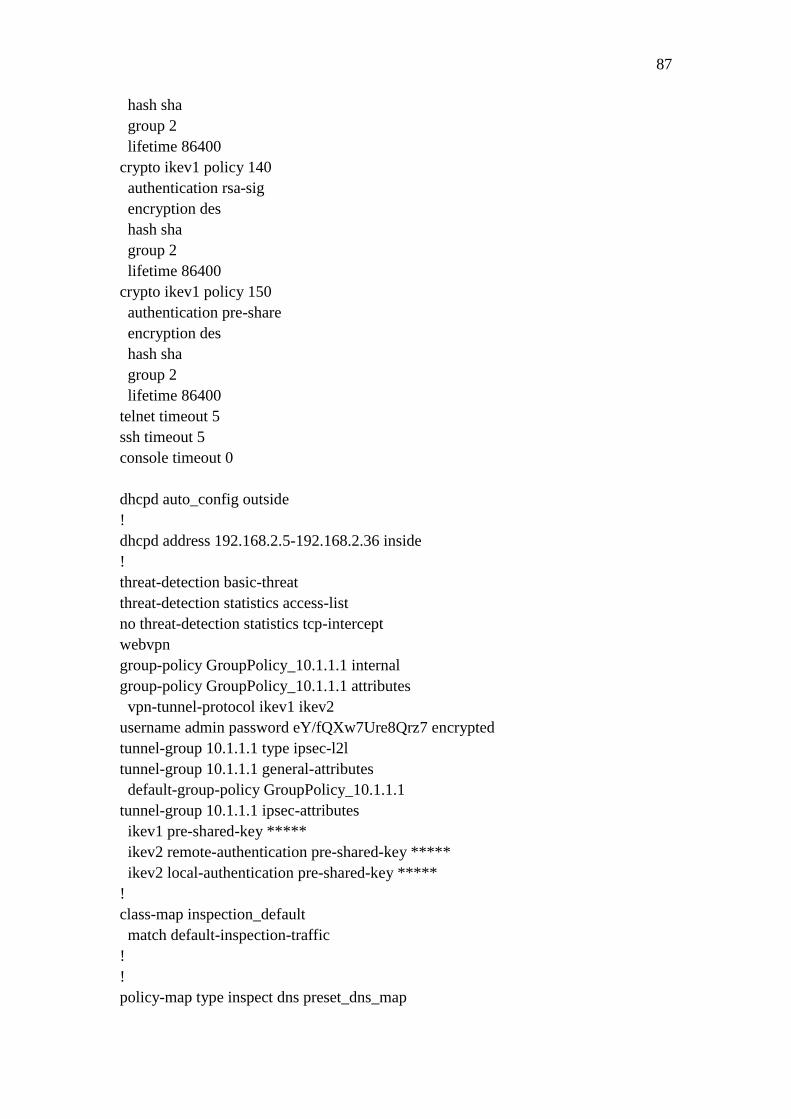
87
hash sha
group 2
lifetime 86400
crypto ikev1 policy 140
authentication rsa-sig
encryption des
hash sha
group 2
lifetime 86400
crypto ikev1 policy 150
authentication pre-share
encryption des
hash sha
group 2
lifetime 86400
telnet timeout 5
ssh timeout 5
console timeout 0
dhcpd auto_config outside
!
dhcpd address 192.168.2.5-192.168.2.36 inside
!
threat-detection basic-threat
threat-detection statistics access-list
no threat-detection statistics tcp-intercept
webvpn
group-policy GroupPolicy_10.1.1.1 internal
group-policy GroupPolicy_10.1.1.1 attributes
vpn-tunnel-protocol ikev1 ikev2
username admin password eY/fQXw7Ure8Qrz7 encrypted
tunnel-group 10.1.1.1 type ipsec-l2l
tunnel-group 10.1.1.1 general-attributes
default-group-policy GroupPolicy_10.1.1.1
tunnel-group 10.1.1.1 ipsec-attributes
ikev1 pre-shared-key *****
ikev2 remote-authentication pre-shared-key *****
ikev2 local-authentication pre-shared-key *****
!
class-map inspection_default
match default-inspection-traffic
!
!
policy-map type inspect dns preset_dns_map

88
parameters
message-length maximum client auto
message-length maximum 512
policy-map global_policy
class inspection_default
inspect dns preset_dns_map
inspect ftp
inspect h323 h225
inspect h323 ras
inspect rsh
inspect rtsp
inspect esmtp
inspect sqlnet
inspect skinny
inspect sunrpc
inspect xdmcp
inspect sip
inspect netbios
inspect tftp
inspect ip-options
!
service-policy global_policy global
prompt hostname context
no call-home reporting anonymous
Cryptochecksum:3ff6a755beb328e31ad98ac3699efd61
: end