measurements before endovascular repair of abdominal ... · system, siemens magnetom vision using a...
TRANSCRIPT
LUND UNIVERSITY
PO Box 117221 00 Lund+46 46-222 00 00
Measurements Before Endovascular Repair Of Abdominal Aortic Aneurysms.
Engellau, Lena; Albrechtsson, Ulf; Dahlström, N.; Norgren, Lars; Persson, A; Larsson, Elna-MariePublished in:Acta Radiologica
DOI:10.1034/j.1600-0455.2003.00029.x
2003
Link to publication
Citation for published version (APA):Engellau, L., Albrechtsson, U., Dahlström, N., Norgren, L., Persson, A., & Larsson, E-M. (2003). MeasurementsBefore Endovascular Repair Of Abdominal Aortic Aneurysms. Acta Radiologica, 44(2), 177-184.https://doi.org/10.1034/j.1600-0455.2003.00029.x
General rightsCopyright and moral rights for the publications made accessible in the public portal are retained by the authorsand/or other copyright owners and it is a condition of accessing publications that users recognise and abide by thelegal requirements associated with these rights.
• Users may download and print one copy of any publication from the public portal for the purpose of private studyor research. • You may not further distribute the material or use it for any profit-making activity or commercial gain • You may freely distribute the URL identifying the publication in the public portalTake down policyIf you believe that this document breaches copyright please contact us providing details, and we will removeaccess to the work immediately and investigate your claim.
Download date: 30. Dec. 2019
MEASUREMENTS BEFORE ENDOVASCULAR REPAIR OF
ABDOMINAL AORTIC ANEURYSMS
MR imaging with MRA vs. angiography and CT
L. ENGELLAU1, U. ALBRECHTSSON
1, N. DAHLSTROM2, L. NORGREN
3, A. PERSSON4 and E.-M. LARSSON
1
1Department of Radiology, Lund University Hospital, Lund, 2Department of Radiology, Hudiksvall Hospital, Hudiksvall,3Department of Vascular Diseases, Lund University, Malmo University Hospital, Malmo and 4Center for Medical Image Science and
Visualization (CMIV), Linkoping University Hospital, Linkoping, Sweden.
Key words: Abdominal aorticaneurysm, endograft sizing; MRangiography, volume renderingtechnique; angiography; CT.
Correspondence: Lena Engellau,Department of Radiology, LundUniversity Hospital, SE-221 85 Lund,Sweden.FAXþ46 46 12 18 37.E-mail: [email protected]
Accepted for publication 18 November2002.
Abstract
Purpose: 1) To compare measurements obtained with MR imaging (MRI)/contrast-enhanced MR angiography (CE MRA) with measurements obtainedwith angiography (DSA) and CT, for stent-graft sizing of abdominal aorticaneurysms (AAA). 2) To compare MRA measurements obtained with the twopost processing techniques MIP (maximum intensity projection) and VRT (3Dvolume rendering technique).
Material and Methods: The prospective study included 20 consecutive patientswith AAA identified by DSA and CT as suitable for endovascular repair. For thestudy, MRI/CE MRA was performed. Five measurement variables for stent-graft sizing were chosen. Comparisons were made between MRI/CE MRA, DSAand CT, and between observers. Comparisons were also made between MIP andVRT.
Results: Significantly shorter lengths were obtained with MRA-MIP than withDSA. Three out of six diameter measurements were significantly smaller onMRI/CE MRA than on DSA and CT. No significant differences were foundbetween the observers. One diameter measurement was significantly smaller onMIP than on VRT, while the other measurements showed no significant differ-ences.
Conclusion: The length measurements obtained with MRA-MIP were prob-ably more correct than those with DSA. For more reliable diameter measure-ments with CE MRA, improvements of the technique, including VRTreconstructions and a standardized determination of the vessel boundaries, areneeded.
Endovascular stent-graft planning in patients withinfrarenal abdominal aortic aneurysms (AAA)requires more accurate morphologic informationand detailed measurements than open repair. Thecontour, length and diameter of the proximal aorticneck, the presence of thrombus and calcification,the angle between the proximal aortic neck and
suprarenal aorta, the anticipated required lengthof the stent-graft, the quality and dimensions ofthe iliac arteries and the presence of any accessoryrenal arteries are relevant (11). The 2D methods,digital subtraction angiography (DSA) and contrast-enhanced (CE) conventional CT, do not provide therequired accuracy for sizing of stent-grafts as sole
Acta Radiologica 44 (2003) 177–184 Copyright # Acta Radiologica 2003
Printed in Denmark � All rights reservedA C T A R A D I O L O G I C A
ISSN 0284-1851
177
imaging methods (3, 4, 9, 16). CE spiral CT angio-graphy (CTA), which is a 3D method, providesmore accurate information (2, 4) and is nowwidely used for stent-graft planning. MR imaging(MRI) with CE MR angiography (MRA) alsoprovides 3D information (6, 16). MRI/CE MRAis non-invasive, does not expose the patient toionizing radiation and uses a non-nephrotoxicparamagnetic contrast agent (10) and would thusbe preferable. The most widely used MRA postprocessing technique is maximum intensity projec-tion (MIP) (13, 14). Volume rendering technique(VRT) is a new promising technique that is similarto MIP, but instead of using the maximum value,which is only about 10% of the available data,in VRT up to 100% of the available data can beused (12).
The purpose of this study was to compare meas-urements obtained with MRI/CE MRA with meas-urements obtained with DSA and CT, the methodsused at our center in planning for endovascular stent-graft repair of AAA. In addition, MRA measurementcomparisons were made between the post processingtechniques MIP and VRT.
Material and Methods
Between January 1995 and November 1998, 20 con-secutive patients (17 men and 3 women; mean age69 years, range 52–77 years) with infrarenal AAA,identified by DSA and CT as potential candidatesfor endovascular repair, were enrolled in this pro-spective study. For the study, MRI with CE MRAwas also performed. (DSA and CT are used asimaging methods for stent-graft planning at ourcenter.)
The Ethics Committee of Lund University approvedthe study protocol. Informed consent was obtainedfrom each patient.
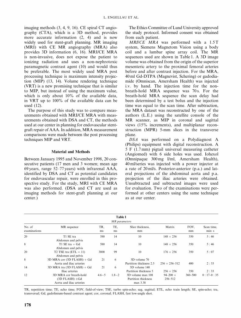
MRI/CE MRA was performed with a 1.5 Tsystem, Siemens Magnetom Vision using a bodycoil and a lumbar spine array coil. The MRsequences used are shown in Table 1. A 3D imagevolume was obtained from the origin of the superiormesenteric artery to the proximal femoral arteriesbefore and after contrast injection. For the MRA,40 ml Gd-DTPA (Magnevist, Schering) or gadodia-mide (Omniscan, Amersham Health) was injectedi.v. by hand. The injection time for the non-breath-hold MRA sequence was 70 s. For thebreath-hold MRA sequence the scan delay hadbeen determined by a test bolus and the injectiontime was equal to the scan time. After subtraction,the MRA dataset was reconstructed by one of theauthors (L.E.) using the satellite console of theMR scanner, as MIP in coronal and sagittalviews (15% increments), and multiplanar recon-struction (MPR) 5-mm slices in the transverseplane.
DSA was performed on a Polydiagnost A(Philips) equipment with digital reconstruction. A5 F (1.7 mm) pigtail universal measuring catheter(Angiomed) with 6 side holes was used. Iohexol(Omnipaque 300 mg I/ml, Amersham Health),40 ml/series was injected with a power injector ata rate of 20 ml/s. Posterior-anterior (p.a.) and lat-eral projections of the abdominal aorta and p.a.projection of the iliac arteries were obtained.Unsubtracted and subtracted images were usedfor evaluation. Two of the examinations were per-formed at other centers using the same techniqueas at our center.
Table 1
MR parameters
No. of MR sequence TR, TE, Slice thickness, Matrix FOV, Scan time,
examinations ms ms mm mm min: s
20 T1 SE tra 580 14 10 148 � 256 350 5 : 46
Abdomen and pelvis
8 T1 SE tra þ Gd 580 14 10 148 � 256 350 5 : 46
Abdomen and pelvis
20 T2 TSE tra (ETL ¼ 11) 3800 99 10 176 � 256 350 5 : 07
Abdomen and pelvis
8 3D MRA cor (3D FLASH) þ Gd 21 6 3D volume 70
Aorta and iliac arteries Partition thickness 2.5 256 � 256–512 400 2 : 33
14 3D MRA tra (3D FLASH) þ Gd 21 6 3D volume 140
Iliac arteries Partition thickness 5 256 � 256 350 2 : 33
12 3D MRA cor breath-hold 4.6�5 1.8�2 3D volume max 108 94–200 � 360–500 0 : 17–0 : 35
(3D FLASH) �Gd Partition thickness 256–512
Aorta and iliac arteries max 3.38
TR, repetition time; TE, echo time; FOV, field-of-view; TSE, turbo spin-echo; sag, sagittal; ETL, echo train length; SE, spin-echo; tra,transversal; Gd, gadolinium-based contrast agent; cor, coronal; FLASH, fast low-angle shot.
L. ENGELLAU ET AL.
178

Spiral CT was performed on a Toshiba Xpress/SX, starting just above the origin of the celiac arteryand covering the iliac bifurcations; 1-s rotationswere executed with a table speed of 5 mm/s. Colli-mation was 5 mm (pitch¼1). Iohexol (Omnipaque300 mg I/ml) 90 ml was given i.v. at a rate of 1.5–2.0 ml/s with a power injector. The scan delay was60 s. The scans were reconstructed as single 5–10-mm-thick slices with an interval of 5–15 mm. Threeof the examinations were performed at other centers.One of these examinations was reconstructed as single10-mm-thick slices with an interval of 15 mm, thesecond as single 4-mm-thick slices with an intervalof 5 mm and the third examination as single 10-mmslices with an interval of 20 mm. The third examin-ation was performed without contrast enhancement.
Measurements on MRI/CE MRA, DSA and CTwere performed individually by three radiologists(L.E. and E-M.L., who were experienced in MRand CT, and U.A., who was experienced in DSAand CT) (Table 2). Five measurement variables forstent-graft sizing were chosen by the radiologistperforming the stent-graft implantations (U.A.)(Fig. 1). Inner diameters (contrast-filled lumen)D1i and D2i were measured on MRA, DSA andCT, while the outer diameters D1� and D2� (includ-ing mural thrombus) were measured on MRI andCT. Missing data for MRA-MIP of L3 measure-ments in 10 patients were due to positioning of the3D volume in CE MRA too far anteriorly, and thusnot including the whole extent of the iliac arteries.One observer (U.A.) judged an additional 4 MRA-MIP examinations to have too poor image qualityfor measurement. For 1 DSA examination all threeobservers found the catheter markers too vague formeasurements (Table 2). The measurements onMRI/CE MRA were made on a PACS workstation(picture archiving and communication system) withthe software system VRS Report (Cedara Software
Corporation, Canada). The optimum window set-ting was chosen by each observer. The accuracy andprecision of the gradients of our MR system werechecked and, if necessary, adjusted 4 times everyyear. The variations have normally been smallerthan 1 pixel (in the order of 1–4 mm) for thesequences used in this study. The MRA-MIP corres-ponding to the p.a. DSA projection was used formeasurements, but the other MIP projections wereavailable. The measurements on DSA were madewith a soft ruler on film. On CT, the measurementswere performed with a ruler on a film viewer withthree-fold magnification. To avoid measurementdifferences caused by different interpretation ofthe proximal margin of the aneurysm, this marginwas marked by U.A. with a line perpendicular tothe aorta on the DSA films. The first slice showingthe proximal portion of the aneurysm was also
Table 2
Number of measurements
Observers Methods Variables
D1i D1� D2i D2� L1 L2 L3
L.E, U.A., MRA-MIP 60 60 60 60 26
E-M.L. DSA 57 57 57 57 57
(Ideally 3 � 20 MRA-MPR 60 60
measurements) CT 55 57
MR-T1 49 60
CT 53 57
A.P., N.D. MIP 20 20 20 20 9
(Ideally 1 � 20 VRT 20 20 20 20 10
measurements)
The variables are explained in Table 1, i ¼ inner diameter, � ¼ outer diameter.
Fig. 1. Measurement variables for stent-graft sizing.
MEASUREMENTS FOR STENT-GRAFT SIZING
179

noted by U.A. on transverse MR-T1 and CTimages. The diameters on MRA-MIP and DSAwere measured perpendicularly to the local lengthaxis of the aorta. If the neck of the distal aorta (D2)had the shape of a cone, the largest diameter wasmeasured. The diameter D1 was measured at themidpoint of the length L1. The lengths were meas-ured in the mid aorta adjusted for tortuosity. Thelevel of the bifurcation of the left common iliacartery was marked by U.A. with a line perpendicu-lar to the common iliac artery. The lengths were notmeasured on MR-T1, MRA-MPR and CT, sincewe had no means to perform length measurementadjusted for the tortuosity with these techniques (4)(Table 2).
The comparisons between the post processingtechniques MIP and VRT using the same MRAdata as above were performed at another center.Two radiologists (A.P. and N.D.) with experienceof VRT measured the variables on MIP and VRT inconsensus (Table 2). The CE MRA datasets wereloaded into a workstation (3D Virtuoso VA31,Siemens) equipped with VolumePro (MitsubishiPrecision Co., Ltd) accelerator graphics card forVRT and MIP post processing. In VRT, a pre-defined preset ramp describing opacity, brightnessand gray scale colors assigned to the voxel histo-gram for the volume-rendering parameters wasselected. The position of the preset ramp due tovarying general signal intensities was adjusted inconsensus. For the MIP a simpler predefined preset,defining window level, was used. The displayedVRT volume or MIP was then magnified to apredefined zoom level. For the measurements onMIP and VRT the volume was kept in its originalposition (Fig. 2), which corresponded to the p.a.DSA projection. A measuring tool that allowsstraight as well as curved measurements was used.The proximal margin of the aneurysm was definedin consensus and marked with a line perpendicularto the local length axis of the aorta at the same levelon MIP and VRT. The DSA films on which U.A.had marked the upper margin of the aneurysm wereavailable for comparison to obtain a similar uppermargin. The diameters were measured perpendicu-lar to the aorta. If the aorta distal to the aneurysmhad the shape of a cone with a proximal base, thelargest diameter was measured. The lengths weremeasured in the mid aorta and iliac vessels adjustedto tortuosity.
Statistical analyses: Clinically accepted variationsof measurement were chosen by U.A.:�2 mm forD1, D2 and L1, �10 mm for L2 and �20 mm for L3.
Comparisons between methods and comparisonsbetween observers were performed. We assessed theagreement between the methods MRA-MIP vs.
DSA, MRA-MPR vs. CT, MR-T1 vs. CT, andMIP vs. VRT by comparing paired measurements,matched on patient and observer. Similarly, weassessed the agreement between the observers U.A.and E-M.L. by comparing paired measurements,matched on patient and method. The measurementsfor the different methods/observers, and of the corres-ponding pairwise differences, were not normally dis-tributed. Method comparisons were therefore basedon non-parametric statistics (1). The location of thedata was expressed by the median and the spread ofthe data by the range or relevant percentiles. Herewe report the percentage of clinically unacceptablevariations of measurement for each variable. Wilcoxonsigned-rank test was used and p-values less than0.05 were considered significant. However, that astatistically significant systematic difference mightbe indicated even though the difference was small andnot clinically significant (1).
We also examined whether there was an associ-ation between patients and observers regardingclinically unacceptable variations of measurement(>�2 mm for the variables D1, D2 and L1 and�10 mm for L2; L3 was excluded because of manymissing measurements) between the methods MRA-MIP vs. DSA and between MIP and VRT. Thiswas done by pairwise comparison between themethods, matched on patient and observer. Theresults were tested with the Chi-square test againstthe frequencies of clinically unacceptable variationsof measurement (no association being the nullhypothesis).
The statistical computations were carried outusing SPSS for Windows (release 10.0.05) andStatXact 5 (Cytel Software Corp.).
a b
Fig. 2. CE 3D MRA. a) MIP and b) VRT, both in p.a. projection.
L. ENGELLAU ET AL.
180

Results
The method comparisons are presented inTables 3–5.
The length measurements obtained with MRA-MIP were significantly shorter than those withDSA. Three of the diameter measurements weresignificantly smaller on MRI/CE MRA than onDSA and CT, while 3 showed no significantdifference.
No significant differences were found between theobservers. The largest interobserver difference wasfound for the variable D2 and for the method CT.
We found no association of patients and obser-vers regarding the clinically unacceptable variationsof measurement between MRA-MIP vs. DSA.
We also studied the vessel morphology of the5 patients with the best agreement of measurementsas well as the 5 patients with the largest differencesof L1 (MRA-MIP vs. DSA) and D2 (MRA-MPRvs. CT) as these differences were clearly significant(Table 4). No differences in vessel tortuosity, angu-lation or aneurysm size were found between the
patients with the best and the least agreement ofmeasurements.
The comparisons between the MRA post process-ing techniques MIP and VRT showed significantlysmaller diameter measurements for D1 on MIP, butno significant differences with regard to the D2 ormeasurements of length (Table 3).
We found no association between patients andobservers regarding the clinically unacceptablevariations of measurement between MIP vs. VRT.
Discussion
A correct length and diameter of the stent-graftminimizes the most common complications ofendovascular repair of AAA: persistent endoleak,stent-graft migration and secondary interventions.Over-sizing of stent-graft diameters may cause fold-ing at the level of the attachment sites, which canresult in misalignment of the stent-graft and thearterial wall. Overinflation of the balloon can stretchand weaken the aorta or iliac arteries. Diameters
Table 3
Measurements in mm: median (range)
Methods Variables
D1i D1� D2i D2� L1 L2 L3
MRA-MIP 18 (12�25) 20 (11�31) 25 (13�74) 120 (91�158) 177 (102�232)
DSA 19 (12�25) 20 (12�39) 31 (12�68) 126 (95�170) 166 (150�179)
MRA-MPR 19 (13�25) 22 (11�38)
CT 21 (13�25) 25 (12�52)
MR-T1 23 (16�31) 30 (15�64)
CT 24 (15�30) 34 (17�61)
MIP 18 (13�24) 20 (11�30) 24 (12�64) 121 (91�160) 164 (148�190)
VRT 20 (14�23) 20 (12�29) 23 (12�62) 118 (91�174) 164 (147�185)
The variables are explained in Table 1.
Table 4
Pairwise differences in mm: median (5th and 95th percentile) and p-values
Methods Variables
D1i D1� D2i D2� L1 L2 L3
MRA-MIP vs. DSA �1 (�6, 3) 0 (�9, 4) �4 (�25, 9) �4 (�17, 5) �6 (�24, 11)
p-value 0.02 0.09 < 0.001 < 0.001 0.03
MRA-MPR vs. CT 0 (�5, 4) �2 (�20, 4)
p-value 0.10 0.004
MR-T1 vs. CT 0 (�5, 5) �2 (�25, 8)
p-value 0.5 0.008
MIP vs. VRT �1 (�3, 0) �1 (�2, 1) 2 (�7, 8) 1 (�3, 9) 3 (�5, 6)*
p-value < 0.001 0.05 0.4 0.16 0.3
The variables are explained in Table 1. Wilcoxon signed-rank test: p-value < 0.05 means that there was a significant systematic difference.*Corresponds to the range of pairwise differences, due to the small number of measurements (8).
MEASUREMENTS FOR STENT-GRAFT SIZING
181
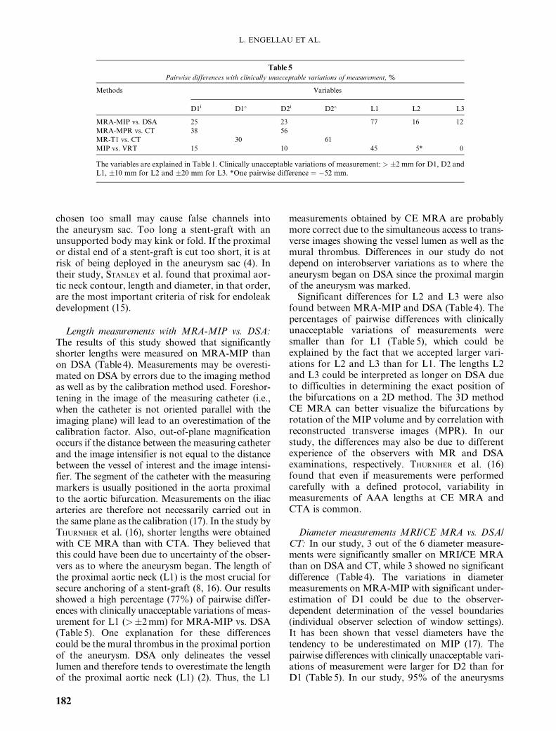
chosen too small may cause false channels intothe aneurysm sac. Too long a stent-graft with anunsupported body may kink or fold. If the proximalor distal end of a stent-graft is cut too short, it is atrisk of being deployed in the aneurysm sac (4). Intheir study, STANLEY et al. found that proximal aor-tic neck contour, length and diameter, in that order,are the most important criteria of risk for endoleakdevelopment (15).
Length measurements with MRA-MIP vs. DSA:The results of this study showed that significantlyshorter lengths were measured on MRA-MIP thanon DSA (Table 4). Measurements may be overesti-mated on DSA by errors due to the imaging methodas well as by the calibration method used. Foreshor-tening in the image of the measuring catheter (i.e.,when the catheter is not oriented parallel with theimaging plane) will lead to an overestimation of thecalibration factor. Also, out-of-plane magnificationoccurs if the distance between the measuring catheterand the image intensifier is not equal to the distancebetween the vessel of interest and the image intensi-fier. The segment of the catheter with the measuringmarkers is usually positioned in the aorta proximalto the aortic bifurcation. Measurements on the iliacarteries are therefore not necessarily carried out inthe same plane as the calibration (17). In the study byTHURNHER et al. (16), shorter lengths were obtainedwith CE MRA than with CTA. They believed thatthis could have been due to uncertainty of the obser-vers as to where the aneurysm began. The length ofthe proximal aortic neck (L1) is the most crucial forsecure anchoring of a stent-graft (8, 16). Our resultsshowed a high percentage (77%) of pairwise differ-ences with clinically unacceptable variations of meas-urement for L1 (>�2 mm) for MRA-MIP vs. DSA(Table 5). One explanation for these differencescould be the mural thrombus in the proximal portionof the aneurysm. DSA only delineates the vessellumen and therefore tends to overestimate the lengthof the proximal aortic neck (L1) (2). Thus, the L1
measurements obtained by CE MRA are probablymore correct due to the simultaneous access to trans-verse images showing the vessel lumen as well as themural thrombus. Differences in our study do notdepend on interobserver variations as to where theaneurysm began on DSA since the proximal marginof the aneurysm was marked.
Significant differences for L2 and L3 were alsofound between MRA-MIP and DSA (Table 4). Thepercentages of pairwise differences with clinicallyunacceptable variations of measurements weresmaller than for L1 (Table 5), which could beexplained by the fact that we accepted larger vari-ations for L2 and L3 than for L1. The lengths L2and L3 could be interpreted as longer on DSA dueto difficulties in determining the exact position ofthe bifurcations on a 2D method. The 3D methodCE MRA can better visualize the bifurcations byrotation of the MIP volume and by correlation withreconstructed transverse images (MPR). In ourstudy, the differences may also be due to differentexperience of the observers with MR and DSAexaminations, respectively. THURNHER et al. (16)found that even if measurements were performedcarefully with a defined protocol, variability inmeasurements of AAA lengths at CE MRA andCTA is common.
Diameter measurements MRI/CE MRA vs. DSA/CT: In our study, 3 out of the 6 diameter measure-ments were significantly smaller on MRI/CE MRAthan on DSA and CT, while 3 showed no significantdifference (Table 4). The variations in diametermeasurements on MRA-MIP with significant under-estimation of D1 could be due to the observer-dependent determination of the vessel boundaries(individual observer selection of window settings).It has been shown that vessel diameters have thetendency to be underestimated on MIP (17). Thepairwise differences with clinically unacceptable vari-ations of measurement were larger for D2 than forD1 (Table 5). In our study, 95% of the aneurysms
Table 5
Pairwise differences with clinically unacceptable variations of measurement, %
Methods Variables
D1i D1� D2i D2� L1 L2 L3
MRA-MIP vs. DSA 25 23 77 16 12
MRA-MPR vs. CT 38 56
MR-T1 vs. CT 30 61
MIP vs. VRT 15 10 45 5* 0
The variables are explained in Table 1. Clinically unacceptable variations of measurement: > �2 mm for D1, D2 andL1, �10 mm for L2 and �20 mm for L3. *One pairwise difference ¼ �52 mm.
L. ENGELLAU ET AL.
182
did not have a clearly delineated non-aneurysmaldistal aorta and therefore D2 was open to individualinterpretation. The method with the highest percen-tage of pairwise differences with clinically unaccep-table variations of measurement was CT (Table 5),which can be explained by the thick transverse CTslices used in our study (3).
Observers: No significant differences were foundbetween the observers. The method with the largestinterobserver difference was CT, which is in agreementwith the study by Jaakkola et al., where conventionalCT measurements were subject to significant inter-observer variability and where this variability wasgreater in transverse planes (7).
MIP vs. VRT: We found that the diameter mea-surement D1 was significantly smaller on MIP thanon VRT, but D2 and the length measurementsshowed no significant differences. The VRT mea-surement of D1 is probably more accurate sincevessel diameters often are underestimated on MIP(17). In our study, we have chosen to compare theMIP with a corresponding 2D image of VRT, andthus have not used the full 3D capacity of VRT.Measurements on 3D VRT should be more accuratethan MIP, since the measurements can be obtainedin 3D and by using VRT in combination with surfaceenhancement, the boundaries between the contrast-enhanced blood and the vessel walls may bevisualized and the diameters will thereby be moreaccurately defined (Fig. 2).
MRI/CE MRA reveals complex, tortuous arterialanatomy; accurately delineates aneurysm size,including proximal and distal extent, mural throm-bus, relationship to major vessels and number andlocation of renal arteries (5, 16). MRI/CE MRAreveals iliac thrombi and aneurysms (5, 16) butis less sensitive for the detection of calcification.STANLEY et al. found that improvements of the deliv-ery systems enabled safe passage through tortuousand calcified iliac vessels (15). The detection ofcalcification should therefore become less important.
A disadvantage of MRI is that it is contraindi-cated in patients with non-MR-compatible metallicimplants and pacemakers. Additionally, a few patientsare unable to undergo an MR examination becauseof claustrophobia. The resolution of MRA in ourstudy is not sufficient for accurate measurementsof small structures, but with the improvement of theCE MRA technique, better results will be obtained.
This study has some limitations. The patientmaterial is rather small and we have no true refer-ence measurement. Comparisons are made betweenanalog (DSA and CT) and digital measurements
(MRI/CE MRA). Due to the development andimprovement of the MR technique, the protocolswere gradually updated, and therefore all examin-ations were not performed with the same protocol.The MR measurements would most likely be moreaccurate if all studies had been obtained usingtoday’s (2003) MR technique. The positioning ofthe 3D volume in CE MRA too far anteriorly, notincluding the whole extent of the iliac arteries,decreased the number of possible L3 measurements.Three CT examinations were performed at othercenters with different protocols. CTA was not avail-able at our center during this study and comparisonwith this method could not be performed.
We conclude that the length measurementsobtained with MRA-MIP were significantly shorter,but probably more correct, than those obtainedwith DSA. The diameter measurements obtainedwith MRI/CE MRA were more variable. Improve-ments of the CE MRA technique including VRTreconstructions and a standardized determinationof the vessel boundaries, are needed for more reliablediameter measurements.
ACKNOWLEDGMENTS
Ulf Stromberg, Department of Occupational and Environmen-tal Medicine is gratefully acknowledged for statistical analyses.
This study was supported by The Skane County CouncilResearch and Development Foundation, Sweden and theLund University Hospital Foundation, Sweden.
REFERENCES
1. Altman DG. Practical Statistics for Medical Research.London: Chapman & Hall, 1991.
2. Armon MP, Whitaker SC, Gregson RH, Wenham PW,Hopkinson BR. Spiral CT angiography versus aortographyin the assessment of aortoiliac length in patients undergoingendovascular abdominal aortic aneurysm repair. J. Endo-vasc. Surg. 1998; 5: 222.
3. Beebe HG. Imaging modalities for aortic endografting.J. Endovasc. Surg. 1997; 4: 111.
4. Broeders IA, Blankensteijn JD, Olree M, Mali W, EikelboomBC. Preoperative sizing of grafts for transfemoral endo-vascular aneurysm management: a prospective comparativestudy of spiral CT angiography, arteriography, and conven-tional CT imaging. J. Endovasc. Surg. 1997; 4: 252.
5. Ecklund K, Hartnell GG, Hughes LA, Stokes KR, Finn JP.MR angiography as the sole method in evaluating abdominalaortic aneurysms. Correlation with conventional techniquesand surgery. Radiology 1994; 192: 345.
6. Fox AD, Whiteley MS, Murphy P, Budd JS, Horrocks M.Comparison of magnetic resonance imaging measurementsof abdominal aortic aneurysms with measurements obtainedby other imaging techniques and intraoperative measure-ments: possible implications for endovascular grafting.J. Vasc. Surg. 1996; 24: 632.
7. Jaakkola P, Hippelainen M, Farin P, Rytkonen H,Kainulainen S, Partanen K. Interobserver variability in
MEASUREMENTS FOR STENT-GRAFT SIZING
183
measuring the dimensions of the abdominal aorta:comparison of ultrasound and computed tomography. EurJ. Vasc. Endovasc. Surg. 1996; 12: 230.
8. Moritz JD, Rotermund S, Keating DP, Oestmann JW.Infrarenal abdominal aortic aneurysms. Implications ofCT evaluation of size and configuration for placement ofendovascular aortic grafts. Radiology 1996; 198: 463.
9. Neschis DG, Velazquez OC, Baum RA, et al. The role ofmagnetic resonance angiography for endoprosthetic design.J. Vasc. Surg. 2001; 33: 488.
10. Niendorf HP, Alhassan A, Haustein J, Clauss W, Cornelius I.Safety and risk of gadolinium-DTPA*: Extended clinicalexperience after more than 5,000,000 applications. Adv.MRI Contr. 1993; 2: 12.
11. Pattynama PMT, Kuiper J-W, Krestin GP. Gap narrowsbetween noninvasive angio tools. Diagn. Imaging Eur.2001; 17: 14–19.
12. Rubin GD, Beaulieu CF, Argiro V, et al. Perspective volumerendering of CT and MR images: applications for endoscopicimaging. Radiology 1996; 199: 321.
13. Rubin GD, Dake MD, Napel S, et al. Spiral CT of renalartery stenosis: comparison of three-dimensional renderingtechniques. Radiology 1994; 190: 181.
14. Rubin GD, Dake MD, Napel SA, McDonnell CH,Jeffrey RB, Jr. Three-dimensional spiral CT angiographyof the abdomen: initial clinical experience. Radiology 1993;186: 147.
15. Stanley BM, Semmens JB, Mai Q, et al. Evaluation ofpatient selection guidelines for endoluminal AAA repairwith the Zenith stent-graft: the Australasian experience.J. Endovasc. Ther. 2001; 8: 457.
16. Thurnher SA, Dorffner R. Thurnher MM, et al. Evaluationof abdominal aortic aneurysm for stent-graft placement:comparison of gadolinium-enhanced MR angiographyversus helical CT angiography and digital subtractionangiography. Radiology 1997; 205: 341.
17. Westenberg JJ, van der Geest RJ, Wasser MN, et al. Vesseldiameter measurements in gadolinium contrast-enhancedthree-dimensional MRA of peripheral arteries. Magn. Reson.Imaging 2000; 18: 13.
L. ENGELLAU ET AL.
184