measuring current and voltage in series circuits - eric
TRANSCRIPT
DOCUMENT RESUME
ED 099 501 CE 002 578
TITLE Module Four: Measuring Current and Voltage in SeriesCircuits; Basic Electricity and ElectronicsIndividualized Learning System.
INSTITUTION Bureau of Naval Personnel, Washington, D.C.REPORT NO NAVPERS-94558-4aPUB DATE Jan 72NOTE 134p.; Photographs are marginally reproducible. For
other modules in theseries, see CE 002 573-589
EDITS PRICE MF-$0.75 HC-$6.60 PLUS POSTAGEDESCRIPTORS Course Content; *Electricity; *Electronics;
Individualized Instruction; Individualized Programs;Industrial Education; Military Training; PostSecondary Education; *Programed Instruction;*Programed Materials; Study Guides; Trade andIndustrial Education; Units of Study (SubjectFields)
ABSTRACTThe module covers the characteristics of series
circuits, how to use the multimeter as an ammeter and voltmeter, andhow to make current and voltage measurements in series circuits. Thismodule is divided into three lessons: measuring current in a seriescircuit, voltage in a series circuit, and using the multimeter as avoltmeter. Each lesson consists of an overview, a list of studyresources, lesson narratives, programed instructional materials, andlesson summaries. (Author/BP)

NAVPERS 945F)8 -4a
S OF PAR !SAE NT OF HEALTHI 01( AtiON d WELT ARE
inryAt INSTITUTE OFI DOC AI ION
.t0 40%."
. ' I . oPINI,Ns
BASIC ELECTRICITY AND ELECTRONICS
INDIVIDUALIZED LEARNING SYSTEM
MODULE FOUR
MEASURING CURRENT AND
VOLTAGE IN SERIES CIRCUITS
Study Bookletc\(
BUREAU OF NAVAL PERSONNELk4,
January 1972

1
OVERVIEW
MODULE FOUR
MEASURING CURRENT AND VOLTAGE IN SERIES CIRCUITS
In this module you will learn the characteristics of a series circuit,
how to use the multimeter as an ammeter and a voltmeter, and how to
make current and voltage measurements in series circuits.
For you to more easily learn the above, this module has been divided
into the following three lessons:
Lesson I. Measuring Current in a Series Circuit . . . .
Lesson II. Voltage in a Series Circuit
Lesson III. Using the Multimeter as a Voltmeter
Do not be concerned at this time with the names or terms unfamiliar to
you. Each will become clear as you proceed. However, if you have
any questions, do not hesitate to call your instructor. Turn to
the following page and begin Lesson I.
BASIC ELECTRICITY AND ELECTRONICS
INDIVIDUALIZED LEARNING SYSTEM
MODULE FOURLESSON I
Measuring Current in a Series Circuit
Study Booklet
3

Overview Four-I
OVERVIEW
LESSON I
Measuring Current in a Series Circuit
In addition to the Modille Overview, as you start each lesson, you will
find a lesson overview like this one. It is merely an outline of what you
will study and learn to do in each lesson. In this lesson you will study
and learn about the following:
- what a series circuit is
-a brief word about parallel circuits
-using a multimeter as an ammeter
- determining current is common in a
series circuit
- practical measurement of DC current
Each of the above topics will be disc.issed in the order listed. As
you proceed through this lesson, observe and follow directions carefully.
BEFORE YOU START THIS LESSON, PREVIEW THE LIST OF STUDY RESOURCES ON
THE NEXT PAGE.
4

Study Resources Four-I
LIST OF STUDY RESOURCES
LESSON I
Measuring Current in a Series Circuit
To learn the material in this lesson, you have the option of choosing,
according to your experience and preferences, any or all of the following:
STUDY BOOKLET:
Lesson Narrative
Programmed Instruction
Lesson Summary
ENRICHMENT MATERIAL:
NAVPERS 93400A-1a "Basic Electricity, Direct Current."
Fundamentals of Electronics. Bureau of Naval Personnel.
Washington, D.C.: U.S. Government Printing Office, 1965.
AUDIO-VISUAL:
Sound/Slide Presentation - "Measuring Current With a Multimeter."
Remember, you may study any or all of these that you feel are necessary
to answer all Progress Check questions correctly. Do not forget that
in one sense of the word your instructor is a living resource; perhaps'
the best. Call him if you have any kind of a problem.
YOU MAY NOW STUDY ANY OR ALE. OF THE RESOURCES LISTED ABOVE. YOU MAY
TAKE THE PROGRESS CHECK AT ANY TIME.
5

Narrative Four-I
NARRATIVELESSON I
Measuring Current in a Series Circuit
What a Series Circuit Is
A series circuit has only one path for current. flow. In the
study of electricity, when we say components are connected inseries, we mean they are connected in line one right after theother.
IVVi --NO/2A
1111
k <
In each of the above circuits, you can see that current has onlyone path it can follow, so that the same amount of current mustflow through each resistor, just as the amount of water flowingthrough a pipe is the same in each part of the pipe.
A Brief Word About Parallel Circuits
A parallel circuit is a circuit that has more than one path forcurrent to follow, as shown by the arrows on the schematic below.
Notice in the above circuit that current from the cell divides intotwo separate paths; whereas, in a series circuit it can take onlyone path.
Using the Multimeter as an Ammeter
You are already familiar with the multimeter as an ohmmeter tomeasure resistance and to take continuity readings. Now you are
6

Narrative Four-I
ready to learn how to use it as an ammeter to take current mea-surements. You can see that the multimeter enables you to useone meter to measure different quantities. The settings and con-nections when using the multimeter as an ammeter will be differentthan the ones used when using it as an ohmmeter.
A Word of Caution: Always connect an ammeter in serieswith the circuit being tested; never in parallel. Failureto do so will damage the meter.
A. B.
NEVER LIKE THIS
Notice in illustration A that the ammeter actually becomes partof the circuit that it. being measured. Total circuit currentmust then flow through the meter.
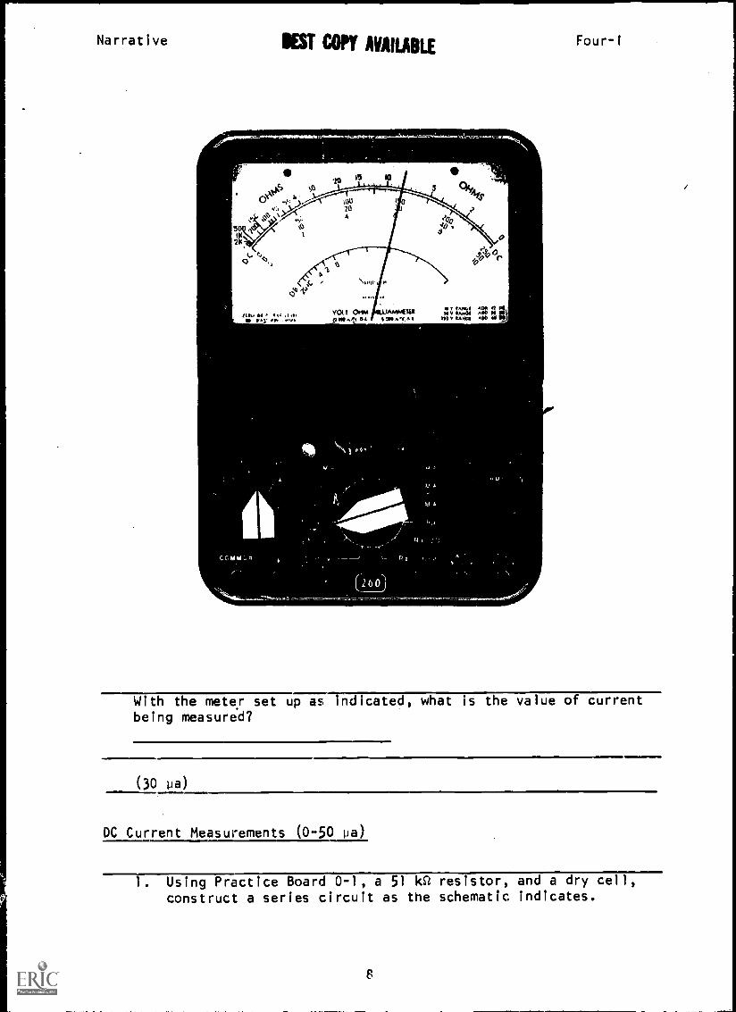
Interpreting the 50 Microampere Scale (Illustration on next page)
The black arc that is labeled DC (second from top) is used for
taking all DC current measurements. When the range selectorswitch is in the 50 m!croamp position, simply read the valueindicated on the 0 -5( scale as microamps.
7
Narrative BEST COPY AVAILABLE
20 15 10= 1
tp,c) 04.4,34
2I3
50IK
,4
'10leo
2K
O
MLA I olMr Ai .1/1
11,1I
YOU Ot 1INNATUIta Ks ,s" 54 $7744,/xt
ia v 14444Inv .Amt
Four-1
With the meter set up as indicated, what is the value of currentbeing measured?
(30 pa)
DC Current Measurements (0-50 pa)
. Using Practice Board 0-1, a 51 ks2 resistor, and a dry cell,
construct a series circuit as the schematic indicates.
El

Narrative Four-I
T6
2. Be sure the switch is open.3. Set up the multimeter as an ammeter to read 0-50 pa DC.
a. Set function switch at +DC.b. Connect black test lead to common (-) jack.c. Connect red lead to the 50 pa jack.d. Attach clips to ends of test leads.e. Set range switch at 50 pa. (Be sure switch is open in
the circuit.)
4. Connect ammeter in series with the circuit by attaching clipsto T7 and T6. Observe polarity.
5. Energize circuit. This completes the circuit; however, thelamp will not light because the resistor limits current somuch that there is not enough current to light the lamp.)
6. Record the reading obtained on the multimeter.
7. Open switch and disconnect meter leads.
You should have had a reading of approximately 28.5 pa.
If the needle deflected in a counter-clockwise direction, you didnot observe polarity when connecting the meter. In this case, re-
verse the leads and try again. Your black lead must be connected
to the side closest to the negative terminal of the source.
Determining Current is Common in a Series Circuit
Current through a series circuit will have the same value anywherein the circuit. This is what we mean when we say that in a series
circuit current is common. To prove this, let's measure current
at another point in the circuit you constructed. You know that
current is approximately 28.5 pa between T7 and T6. Now we will
measure between T2 and T3.
1. Be sure circuit is de-energized.2. Reconnect circuit as shown in
the schematic, with the ammeterbetween T2 and T3.
3. Your meter is already set up.
9
T1 51KR T2 T3
DS1
T7

Narrative
4. Energize the circuit and read thevalue of current. Did
you get the ...;ame reading you ob-tained at the first point ofmeasurement?
5. De-energize the circuit and dis-connect meter.
6. Now reconnect circuit to conformto this schematic.
7. With switch in open position,connect ammeter between T7 andT8, observing polarity. Read
the value of current.8. Disconnect the meter.
Four-I
Notice that when the ammeter was connected across the open switch,the meter served to close the circuit, thus you can see that theammeter actually becomes part of the circuit.
Yoe have now taken current readings in three different places in thecircuit and found that the readings were the same in each instance -proof that current is common in a series circuit.
10

Narrative Four-1
BEST COPY AVAILABLE
500 ma, 100 ma, 10 ma, and 1 ma ScalesInterpreting the
For readingarc and the
milliamps on the meter, we still use the same black DCthree rows of numbers directly under it.
'T
.1k1 15 10
3 Oh4,40L
05d
O
>7. 4<1
stS
r
Vol I 014A MADAMMEItilplT^.s D. 7/4 , g;:r.m.
TO I..06 AM 48 Me
11
'1.

Narrative Four-IBEST COPY AIIPP._*!::.
Notice the three .*ows of numbers under the black DC arc are cali-brated 0-250, 0-50 and 0-10. If the range selector switch is onthe 500ma position as shown, you simply add a zero to every numberon the 0-50 scale. What you are really doing is multiplying by 10.
50
2KA
ti
6
zoo 0, . o LIS14111. 1.111 01-14.4
200
iJOst
VO(10.1*VAILLAPAWOihMat 40 0
jog4.41/0. S.9111n/V AC stiV midi MSIIIV WWII AO
12

Narrative Four-I
With meter set up as indicated in preceding illustration,what the current reading?
a. 2 ma
b. 2 a
c. 10 0a
d. 100 ma
ANSWER - (d) 100 ma
13

Narrative ..)1*..!Pii.
BEST COPY At /Ali rFour- I
If the range selector is on the 100 ma position, you simplyadd e zero to every number on the 0-10 scale. Here you arereally multiplying by 10.
5011(
Pi
sitkdr
.1. }
,k),.,
.\>.;.,,,. -- ''..
%1;71
'20 15
w.121.1
A
10
rr.T._._.. 5osi,Si,5
'-r--
d01 I OHM NOLLAMMinit,to^ 41, dr, v4
14
o°
V.011 &01 r 0016 V 1,v0I A00 16 00
VAI02 11,0 40 00

Narrative Four-I
With the meter set up as indicated in the preceding illustration,what is the reading?
a. 8 a
b. 40 ma
c. 80 ma
d. 80 pa
ANSWER - (c) 80 ma
15

Narrative Four-I
BEST COPY AVAILABLE
If the range selector is set on the 10 ma position as indicated,all we do is read it directly on the 0-10 scale.
O
hV0
tOW D6 ... 16 LIVIISt *Alt fA0 CIWAS
20
16020 JOA 6
\ tintt.4 Si
0%410,s -r It
y01,1 INAKTUIA) Orr AY DC AM AI% AC
16
,r4
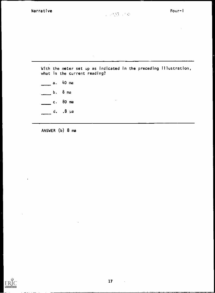
Narrative Four- I
With the meter set up as indicated in the preceding illustration,what is the current reading?
a. 40 ma
b. 8 ma
c. 80 ma
d. 8 pa
ANSWER (b) 8 ma
17

Narrative Four-I
BEST COPY 4111111 r
With the range selector set on the 1 ma scale as indicated,we read on the 0-10 scale and make each number a decimal .1,
.2, .3, .4, .5, etc. Here you can see you are really dividingby 10.
24
.,
Jiro 01 Ii .ArIA, t. OnIAS
OeffA
150
2G Jo
40'
v01 I wt LIA1014111pal a 4-47t1 coo nee wt
IANGI Aeo
2rZ $

Narrative Four-i
With the meter set up as indicated in the preceding illustration,what is the current reading?
a. 0.2 a
b. 0.2 ma
c. 20 ma
d. 2 0
ANSWER - (b) 0.2 ma
T2
TT
Measuring DC Current (0-500 ma)
1.
2.
Usingresistorstructas
Set
ma
Practice Board 10-1, a 330 Q
and one dry cell, con-Tipart of a series circuit
shown.R=330 0
up the multimeter to read 0-500
The
DC.
a.
b.
c.
d.
Set function switch to +DC. 116-410...°16---Connect black test lead in common (-) jack. T8Connect red lead in the (+) jack.Set range switch to highest ma setting (500 ma).reason for this is that we do not know how much current
will be flowing. Since current flow is still unknown,starting at the highest ma range setting can preventdamage to the meter.
e. Be sure switch is open.
3. Connect the meter in series as shown,observing polarity.
4. Close the switch.5. If you get no needle deflection,
change the range selector to oneof the other ma positions untilyou get as close to a mid-scalereading as possible.
T1 T2
T8 T7
You should find that the reading is almost mid-scale atthe 10 ma setting.
19

Narrative Four-I
6. To read the scale for a 10 ma setting, use the black DC arcand read the 0-10 figures directly. Record current.
7. De-energize the circuit and remove test leads.
You should have read approximately 4.4 ma.
AT THIS POINT, YOU MAY TAKE THE PROGRESS CHECK, OR YOU MAY STUDY ANYOF THE OTHER RESOURCES LISTED. IF YOU TAKE THE PROGRESS CHECK ANDANSWER ALL OF THE QUESTIONS CORRECTLY, GO TO THE NEXT LESSON. IF NOT,
STUDY ANY METHOD OF INSTRUCTION YOU WISH UNTIL YOU CAN ANSWER ALL THEQUESTIONS CORRECTLY.
20
P. I .
PROGRAMMED INSTRUCTIONLESSON I
Four-I
Measuring Current in a Series Circuit
TEST FRAMES ARE 5, 8, 12, 15, 19, 23, 33, 36, 44, 48, 59, 61, and64. AS BEFORE, GO FIRST TO TEST FRAME 5 AND SEE IF YOU CAN ANSWERALL THE QUESTIONS THERE. FOLLOW THE DIRECTIONS GIVEN AFTER THETEST FRAME.
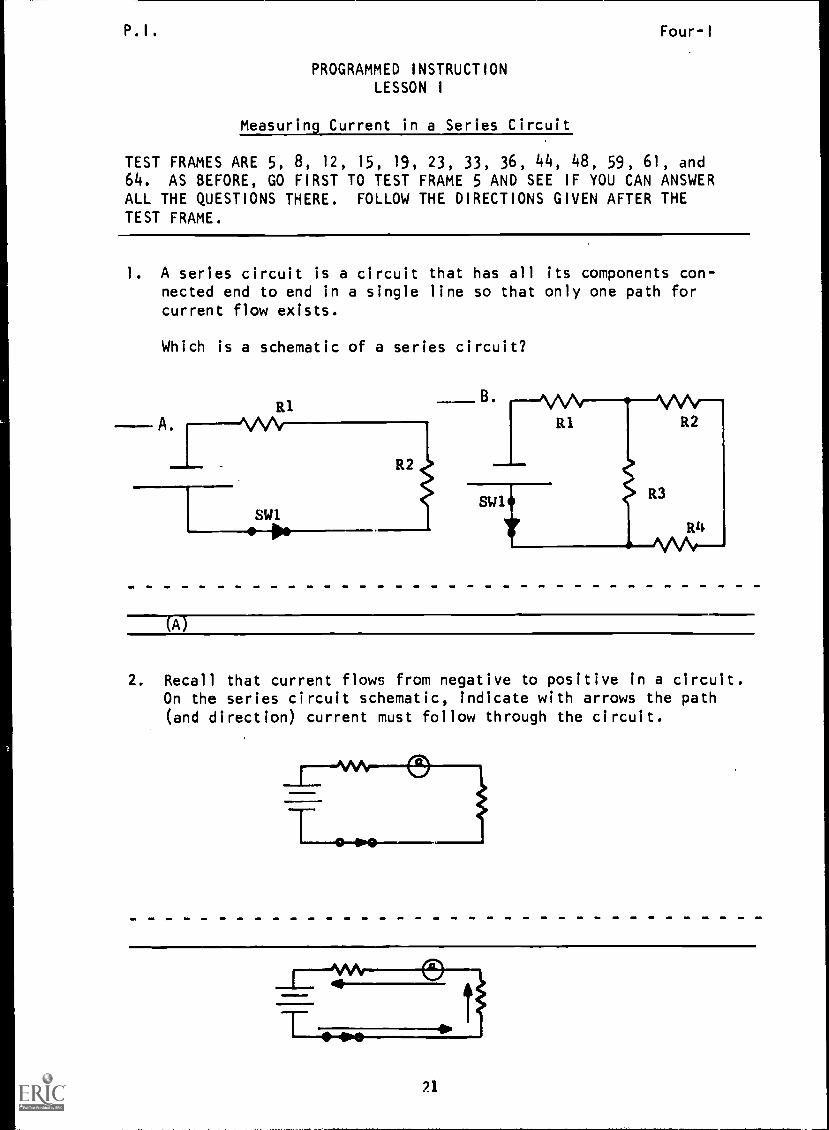
1. A series circuit is a circuit that has all its components con-nected end to end in a single line so that only one path forcurrent flow exists.
Which is a schematic of a series circuit?
R1
A. VA/
R2
SW1
(A)
2. Recall that current flows from negative to positive in a circuit.On the series circuit schematic, indicate with arrows the path(and direction) current must follow through the circuit.
21
P.I.. Four-I
3. Since current in a series circuit has only one path to follow,the same amount of current will flow through each component inthe circuit.
In a series circuit:
a. current will be greater through the negative terminalof the cell than through the positive terminal.
b. current will be the same (common) throughout the circuit.c. current flow will differ through each component in the
circuit.d. the same amount of current will leave the battery as
will return.
(b. current will be the same (common) thrcughout the circuit; and,d. the same amount of current will leave the battery es willreturn.)
4. When the same amount of current flows through each and every partof the circuit, the circuit is said to be connected in
(series)
5. Check the correct definition of a series circuit.
a. two or more components providing a path for current flowb. two or more components connected end to end to form only
one path for current flow.
(THIS IS A TEST FRAME. COMPARE YOUR ANSWERS WITH THE CORRECTANSWERS GIVEN AT THE TOP OF THE NEXT PAGE.)
22

P.I. Four-I
ANSWERS - TEST FRAME 5
b. two or more components connected end to end to formonly one path for current flow.
IF YOUR ANSWER MATCHES THE CORRECT ANSWER, YOU MAY GO ON TO TESTFRAME 8. OTHERWISE, GO BACK TO FRAME 1 AND TAKE THE PROGRAMMEDSEQUENCE BEFORE TAKING TEST FRAME 5 AGAIN.
6. Since current is common in a series circuit, the amount of currentanywhere in the circuit will equal the total current drawn fromthe source.
What is the amount of current flow through the points indicated?
3AtIPS RI
a. AMPS
AMPS
AMPS
a. 3 amps; b. 3 amps; c. 3 amps
7. The amount of current flow anywhere in a series circuit is (equalto/different from) the total current drawn from the source.
(equal to)
23

P.I. Four-I
8. Determine and record the indicated values of circuit current.
A.
IR 1
5 AMPS
IR 2
B.
A. I
R2B. I
111
(THIS IS A TEST FRAME. COMPARE YOUR ANSWERS WITH THE CORRECTANSWERS GIVEN AT THE TOP OF THE NEXT PAGE.)
714

P.I. Four-I
ANSWERS - TEST FRAME 8
a. =5 amps
b. =2 amps
IF ALL YOUR ANSWERS MATCH THE CORRECT ANSWERS, YOU MAY GO ON TO
TEST FRAME 12. OTHERWISE, GO BACK TO FRAME 6 AND TAKE THE PRO-GRAMMED SEQUENCE BEFORE TAKING TEST FRAME 8 AGAIN.
25

P.I. BEST COPY AVAILABLE Four- I
9. A parallel circuit differs from a series circuit in that it hastwo or more paths for current flow. Two examples of parallelcircuits are shown below.
A.
2 PATHS
3 PATHS
rilIndicate with arrows the current paths in the parallel circuits.In the spaces below each circuit, write the number of paths thatexist for current flow.
NUMBER OF PATHS
B.
/1NUMBER OF PATHS
A.
(a. 3; b. 4)
B.
26

P.I. Four-I
10. Each path for current flow is called a branch. How many
branches are there in the circuit below?
(3 branches)
11. Match the kind of circuit to its correct definition.
1. circuit that has two or more a. parallel circuitpaths for current flow
2. circuit that has two ormore components connectedend to end to form only onepath for current flow.
b. series circuit
71. a; 2. b)
27

P. I. Four - I
12. Match the schematics to their appropriate characteristics.
1. more than one path for current flow
2. series circuit
3. parallel circuit
4, only one path for current flow
(THIS IS A TEST FRAME. COMPARE YOUR ANSWERS WITH THE CORRECTANSWERS GIVEN AT THE TOP OF THE NEXT PAGE.)
28

P.I. Four-I
ANSWERS - TEST FRAME 12
1. B, D
2. A, C
3. B, D
4. A, C
IF ALL YOUR ANSWERS MATCH THE CORRECT ANSWERS, YOU MAY GO ON TOTEST FRAME 15. OTHERWISE, GO BACK TO FRAME 9 AND TAKE THE PRO-GRAMMED SEQUENCE BEFORE TAKING TEST FRAME 12 AGAIN.
13. When using the multimeter as an ammeter for measuring DC current,it must always be connected in series with the load. Remember --
in series means in a line.
Which schematic shows the multimeter correctly installed as anammeter?
A.
011. YIMMOMMIIIN
B.
(A)
29
P.I. Four-I
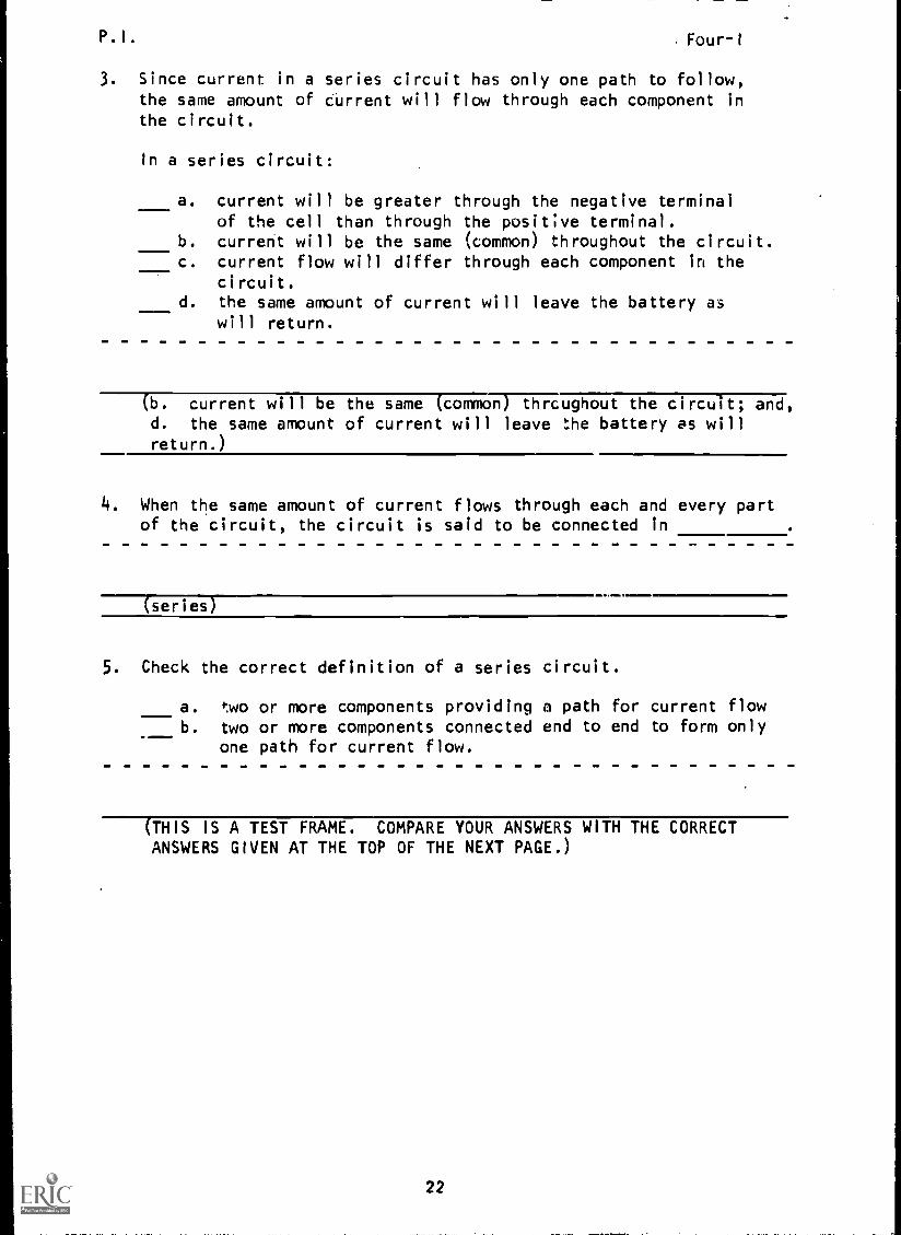
14. To connect an ammeter (multimeter) properly in a circuit, polaritymust be observed. The negative side of the meter must be connectedto the negative side of the source, and the positive side of themeter to the positive side of the source.
Which schematic shows the multimeter correctly installed as anammeter?
(B)
15. Check the schematic that shows the meter correctly installed.
A.
(THIS IS A TEST FRAME. COMPARE YOUR ANSWERS WITH THE CORRECTANSWERS GIVEN AT THE TOP OF THE NEXT PAGE.)
30

P.I. Four-IBEST COPY AVAILABLE
ANSWER - TEST FRAME 15
A
IF YOUR ANSWER MATCHES THE CORRECT ANSWER, YOU MAY GO ON TO TEST
FRAME 19. OTHERWISE, GO BACK TO FRAME 13 AND TAKE THE PROGRAMMEDSEQUENCE BEFORE TAKING TEST FRAME 15 AGAIN.
16. The illustration below shows the front panel and controls asso-ciated with the ammeter function of the Simpson 260-5P multimeter.Study the illustration, then locate these components and con-trols on your multimeter.
m N
1;f2"r
DC SCALE
til 1,10 sel.144dNeill4.
-10A JACK
FUNCTION SWITCH
COMMON(-) JACK JACK
10A JACK
SOuA JACK
RANGE SWITCH
(Go to next frame.)
31
P.I. Four-I
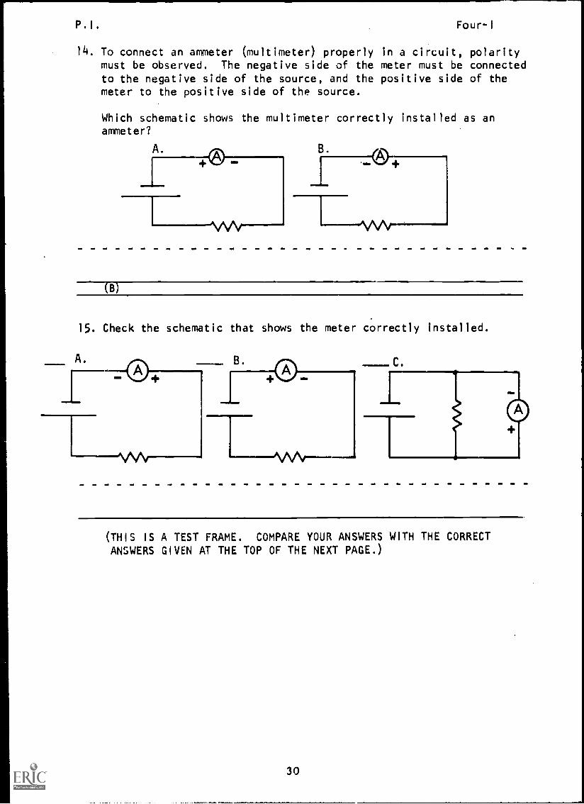
17. Locate the function switch on your multimeter.
What are the three positions to which the function switch canbe moved? (Any order)
a.
b.
c.
(-DC; +DC; AC)
18. The position of the function switch determines whether the multi-meter is to be used to measure AC or DC values. When used as anammeter for measuring direct current, the function switch canbe in either of the DC positions. (Except for use in the 50 paor 10 amp range. These ranges require +DC setting.)
What function switch setting(s) could be used when measuringdirect current?
a.
b.
c.
4a;AC
AC
a' c
32
P.I. Four-I
19. To measure direct current, the function switch must be in theor the positions. (Any order)
(THIS IS A TEST FRAME. COMPARE YOUR ANSWERS WITH THE CORRECT
ANSWERS GIVEN AT THE TOP OF THE NEXT PAGE.)
33
P. I .
BEST COPY AVAILAKE Four - I
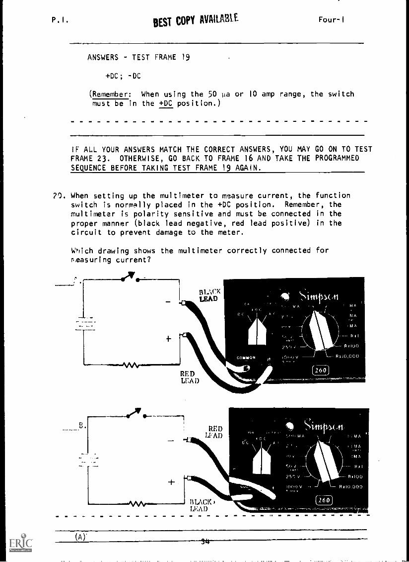
ANSWERS TEST FRAME 19
+DC; -DC
(Remember: When using the 50 pia or 10 amp range, the switchmust be in the +DC position.)
IF ALL YOUR ANSWERS MATCH THE CORRECT ANSWERS, YOU MAY GO ON TO TESTFRAME 23. OTHERWISE, GO BACK TO FRAME 16 AND TAKE THE PROGRAMMEDSEQUENCE BEFORE TAKING TEST FRAME 19 AGAIN.
70. When setting up the multimeter to measure current, the functionswitch is normally placed in the +DC position. Remember, themultimeter is polarity sensitive and must be connected in theproper manner (black lead negative, red lead positive) in the
circuit to prevent damage to the meter.
Which drawing shows the multimeter correctly connected forpeasuring current?
.--.=10Ar.
BLACKLEAD
% . .
RE DLEA D
RED11 AD
LEAD
I
IS
( A )'

.
BEST COPY AVAILABLEFour-1
21. If for some reason the meter is connected improperly, the function
switch can be used to change the polarity of the meter without
removing the meter leads from the circuit under test. (This does
not apply to the 50 or the 10 amp range.)
The illustration below shows an improper meter connection.
Check the function-switch position you would use to correct the
meter connection shown above.
a.
b.
c.
+pc-DCAC
+DC
(a)
35
P.I. Four-I
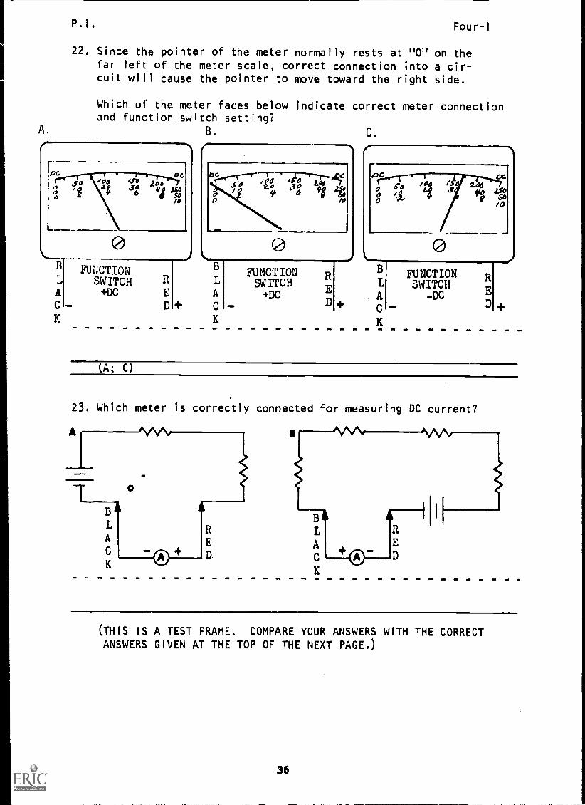
22. Since the pointer of the meter normally rests at "0" on thefar left of the meter scale, correct connection into a cir-cuit will cause the pointer to move toward the right side.
Which of the meter faces below indicate correct meter connectionand function switch setting?
B. C.
PC pG0 X00
2 411; 2"ocja 6
K
/0
0
/
clI7r) t1 46 fIri 42fif 44 Jg fl 1
FUNCTIONSWITCH+DC
RED
B
AC
K
FUNCTIONSWITCH+DC
ED
B
A
C
K
206SI 4SSo
/0
0FUNCTIONSWITCH
-DC ED
(A; C)
23. Which meter is correctly connected for measuring DC current?
Al B I AVVIV MeV
0
BAL RA
K
(THIS IS A TEST FRAME. COMPARE YOUR ANSWERS WITH THE CORRECTANSWERS GIVEN AT THE TOP OF THE NEXT PAGE.)
36

P.I. Four-I
ANSWERS - TEST FRAME 23
A
IF ALL YOUR ANSWERS MATCH THE CORRECT ANSWERS, YOU MAY GO ON TO
TEST FRAME 33. OTHERWISE, GO BACK TO FRAME 20 AND TAKE THE PRO-
GRAMMED SEQUENCE BEFORE TAKING TEST FRAME 23 AGAIN.
24. Locate the range switch on your multimeter. The range switch
also determines how the meter will be used. For example, when
used as an ohmmeter for measuring resistance, the followingrange settings are used:
Rx1
Rx100
Rx100C
Rifer to your Simpson 260-5P multimeter. Which drawing shows the
range switch settings that would be used to measure direct current?
A. B.
(A)
25. Look at the range-switch positions on your multimeter. The
maximum DC current measurement possible with the Simpson 260-5P
multimeter is:
a. 500 ma DC.
b. 10 amps DC.
c. 100 amps DC.
d. 50 pa DC.
(b)
37

P.I. Four-1
26. List the five positions of the range switch that are usedto measure D. . current. (Any order)
(50 pa; 500 ma; 100 ma; 10 ma/10 amps; 1 ma)
27. Each current range-switch setting represents the maximum amp-erage that the multimeter is capable of measuring when in thatposition. For example, if the range switch is set at 50 pa,this means that the current range is 0-50 pa; if the rangeswitch is set at 10 ma, the current range would be 0-10 ma.
What would the current range be if the range switch was set at500 ma?
a. 100-500 ma
b. 0-500 mac. 10-500 ma
(b) 0-500 ma
28. Look at the current range switch positions again. Then list thecurrent ranges the meter is designed to measure. (Any order)
0-50 pa; 0-1 ma; 0-10 ma/amps; 0-100 ma; 0-500 ma)
3R
A.
P.I. BEST COPY AVAILABLE Four-I
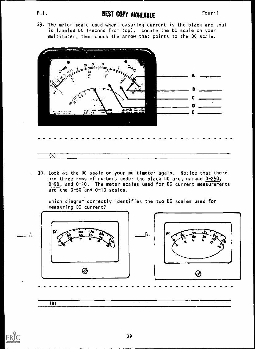
29. The meter scale used when measuring current is the black arc thatis labeled DC (second from top). Locate the DC scale on yourmultimeter, then check the arrow that points to the DC scale.
50
2K
oft 15 10
,-," \ ,.1.-r.--a. I 4.1.4181/4, ...p '' ,au IS.,
S 9.1
20 .St.' .)4' ,Jt'%>A' A 0". Ion
0 40'c1
lit Li il
v2 1
A
(B)
30. Look at the DC scale on your multimeter again. Notice that thereare three rows of numbers under the black DC arc, marked 0-250,0-50, and 0-10. The meter scales used for DC current measurementsare the 0-50 and 0-10 scales.
Which diagram correctly identifies the two DC scales used formeasuring DC current?
(B)
39

P.I. Four-1
31. The position of the range switch (50 pa, 500 ma, 100 ma,
10 ma/amps, 1 ma) will determine whether the 0-10 DC scale or
the 0-50 DC scale is used. When the range switch is in the
50 pa position, the 0-50 scale is used.
Which meter scale is used to read 0-50 pa DC?
I
100 15020 30
10 6 0 z!.51.0
a. 8 SOb. 0 2oC. 0
b
32. When the range switch is in the 50 pa position, current is readdirectly on the 0-50 scale.
What would the current reading be for the illustration?
100 /50
50 20 30 200
010 14 6 40
8%
0 f?. so
0 .lo
50AMPS
a. 103 microamps
b. 23 microamps
c. 7 microamps
(b) 23 microamps
40
P. 1 .
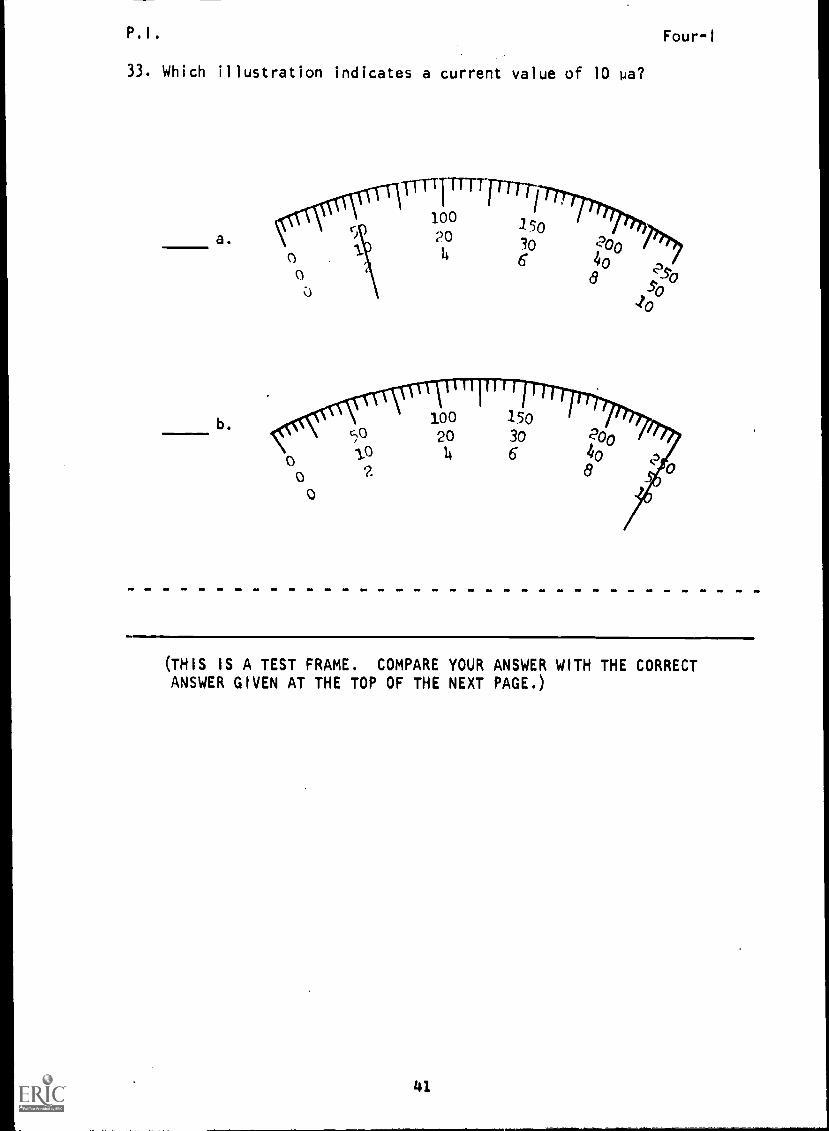
33. Which illustration indicates a current value of 10 pa?
a.
b.
Four-1
(THIS IS A TEST FRAME. COMPARE YOUR ANSWER WITH THE CORRECTANSWER GIVEN AT THE TOP OF THE NEXT PAGE.)
41

P. I .
BEST COPY 11VAIIPRI E
/....
ANSWER - TEST FRAME 33
a
Four-I
IF YOUR ANSWER MATCHES THE CORRECT ANSWER, YOU MAY GO ON TO TEST
FRAME 36. OTHERWISE, GO BACK TO FRAME 24 AND TAKE THE PROGRAMMEDSEQUENCE BEFORE TAKING TEST FRAME 33 AGAIN.
34. When using the multimeter to read 0-50 pa DC, the common (-)
jack and the 50 pa jack are used.
Using the illustration below, locate on your multimeter thecommon (-) jack and the 50 pa jack.
SOuAMPS
COMMON (:)
Go to next frame
42

P. I . Four-I
35. On the illustraion below, che:k the arrows which point to thejacks used when making current measurements in the range 0-50 pa.
b.
(b; c)
36. List the names of the two jack positions used when making DCcurrent measurements in the 0-50 pa range. (Any order)
a.
b.
(THIS !S A TEST FRAME. COMPARE YOUR ANSWERS WITH THE CORRECT
ANSWERS GIVEN AT THE TOP OF THE NEXT PAGE.)
43
P.I. Four-I
ANSWERS - TEST FRAME 36
a. 50 pa jack
b. common (-) test jack
IF ALL YOUR ANSWERS MATCH THE CORRECT ANSWERS, YOU MAY GO ON TO TESTFRAME 44. OTHERWISE, GO BACK TO FRAME 34 AND TAKE THE PROGRAMMEDSEQUENCE BEFORE TAKING TEST FRAME 36 AGAIN.
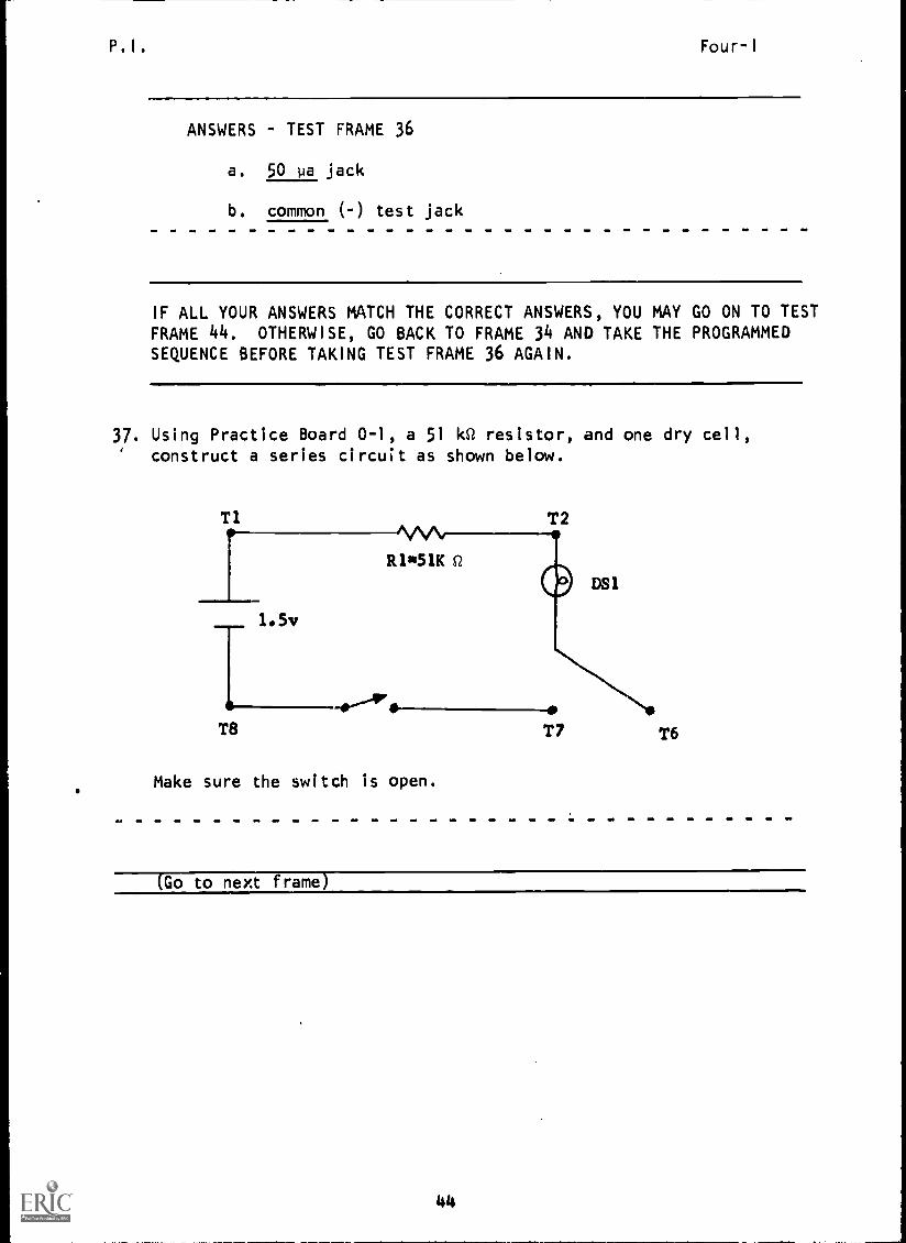
37. Using Practice Board 0-1, a 51 kR resistor, and one dry cell,' construct a series circuit as shown below.
Tl T2
T8
Make sure the switch is open.
T7No
T6
(Go to next frame)
44

P. I . BEST COPY AVAILABLE Four-I
38. Listed below are the proper steps for setting up the multimeterfor measuring DC current in the 0-50 pa range.
1. Set the function switch at +DC.2. Connect the black test lead in the common (-)
jack and the red test lead in the 50 pajack. (Use test leads with clips.r-
3. Set the range switch at 50 pa.
Following the steps listed above, set up your multimeter, thencheck your meter setup against this illustration.
BLACKTESTLEAD
REDTESTLEAD
(Go to next frame)
39. Take the series circuit you have constructed and connect the meterin series with the load (between T6 and T7), connecting the redtest lead toward the positive side of the source and the blacktest lead toward the negative side. MAKE SURE THE SWITCH ISBEFORE CONNECTING THE METER.
Ti T2
1.5v
T8
R1051K
T6
(open)
45
P. I .
Four-1
40. Energize circuit and observe the meter pointer. If it is de-
flected to the left, the polarity is opposite to that which was
anticipated. De-energize the circuit, reverse the meter leads,
and energize circuit again. (Note: Meter polarity cannot be
reversed b; using the function switch except when measuring
milliamps.)
(Go to the next frame.)
41. Read the current directly on the black DC arc using the 0-50
scale. What is the amount of current flowing in the circuit?
(approximately 28.5 ua)
42. De-energize the circuit and remove the test leads from the circuit.
Restore the circuit to its normal working condition.
(Go to next frame)
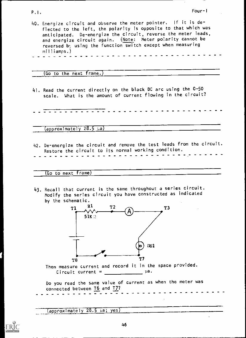
43. Recall that current is the same throughout a series circuit.Modify the series circuit you have constructed as indicated
by the schematic.
Ti R1 T2 T3
51K,?
DS1
T8 T7
Then measure current and record it in the space provided.
Circuit current = pa.
Do you read the same value of current as when the meter was
connected between T6 and T7?
(approximately 28.5 ua; yes)
46
P.I. Four-I
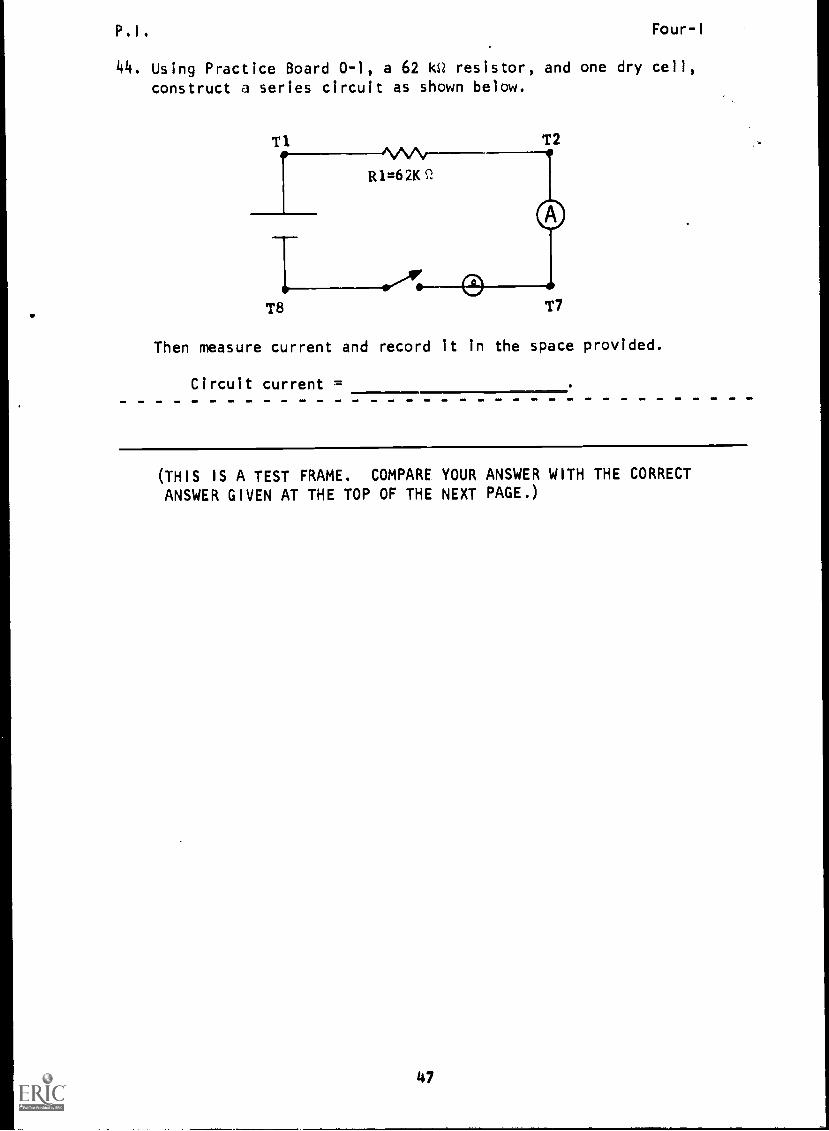
44. Using Practice Board 0-1, a 62 kSt resistor, and one dry cell,construct a series circuit as shown below.
T1
T8
T2
T7
Then measure current and record it in the space provided.
Circuit current =
(THIS IS A TEST FRAME. COMPARE YOUR ANSWER WITH THE CORRECT
ANSWER GIVEN AT THE TOP OF THE NEXT PAGE.)
47
(b)
48
P.I. Four-I
ANSWER - TEST FRAME 44
23-26 pa
(Note: The lamp will not light because the resistor,in this instance, greatly limits the current flow.)
IF YOUR ANSWER MATCHES THE CORRECT ANSWER, YOU MAY GO ON TO TESTFRAME 48. OTHERWISE, GO BACK TO FRAME 37 AND TAKE THE PROGRAMMEDSEQUENCE BEFORE TAKING TEST FRAME 44 AGAIN.
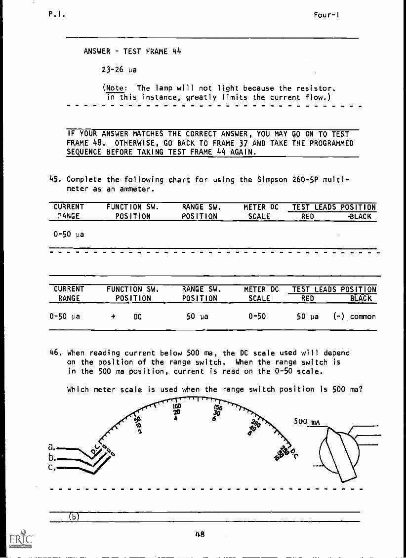
45. Complete the following chart for using the Simpson 260-5P multi-meter as an ammeter.
CURRENT FUNCTION SW. RANGE SW. METER DC TEST LEADS POSITIONPANGE POSITION POSITION SCALE RED -BLACK
0-50 pa
CURRENT FUNCTION SW. RANGE SW. METER DC TEST LEADS POSITIONRANGE POSITION POSITION SCALE RED BLACK
0-50 pa + DC 50 pa 0-50 50 pa (-) common
46. When reading current below 500 ma, the DC scale used will dependon the position of the range switch. When the range switch isin the 500 ma position, current is read on the 0-50 scale.
Which meter scale is used when the range switch position is 500 ma?
30wa Is°213
A 6 500 mA
41111!<141"1
CY q

P 1 . BEST COPY AVAILABLEFour-I
47. If the range switch is in the 500 ma position, the value indicated
on the 0-50 scale must be multiplied by 10 to obtain the amount
of current. For example, with the meter set up as shown below,
the current flow would be 200 ma.
500 mA 100mA10 mA
AMPS1 mA
50P AMPS
What is the current reading indicated below? ma
ti
cr-t
234
500 mA
(350)
49

P.I. Four-I
48. What is the current reading Indicated below?
a. 40 ma
b. 430 ma
c. 230 ma
d. 80 ma
vocr q.(1,
500 tuA
50u
AMPS
100 mA
10 mA AMPS
1 mA/
(THIS IS A TEST FRAME. COMPARE YOUR ANSWER WITH THE CORRECTANSWER GIVEN AT THE TOP OF THE NEXT PAGE.)
50
P.I. Four-I
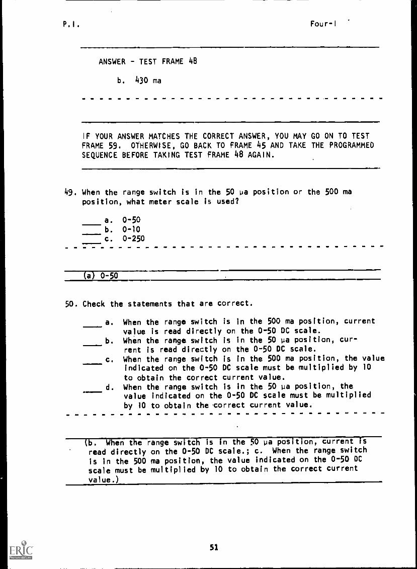
ANSWER - TEST FRAME 48
b. 430 ma
IF YOUR ANSWER MATCHES THE CORRECT ANSWER, YOU MAY GO ON TO TESTFRAME 59. OTHERWISE, GO BACK TO FRAME 45 AND TAKE THE PROGRAMMEDSEQUENCE BEFORE TAKING TEST FRAME 48 AGAIN.
49. When the range switch is in the 50 ua position or the 500 maposition, what meter scale is used?
a. 0-50b. 0-10c. 0-250
(a) 0-50
50. Check the statements that are correct.
a. When the range switch is in the 500 ma position, current
value is read directly on the 0-50 DC scale.b. When the range switch is in the 50 pa position, cur-
rent is read directly on the 0-50 DC scale.
c. When the range switch is in the 500 ma position, the valueindicated on the 0-50 DC scale must be multiplied by 10
to obtain the correct current value.d. When the range switch is in the 50 is position, the
value indicated on the 0-50 DC scale must be multiplied
by 10 to obtain the .correct current value.
(b. When the range switch is in the 50 pa position, current isread directly on the 0-50 DC scale.; c. When the range switch
is in the 500 ma position, the value indicated on the 0-50 DC
scale must be multiplied by 10 to obtain the correct current
value.)
51

P.I. BEST COPY AMIABLE Four-I
51. For the rema ning range positions, 1 ma, 10 ma, and 100 ma, the
0-10 DC scale is used. If the range switch is in the 100 maposition, the value indicated on the 0-10 DC scale must be multi-
plied by 10.
What is the current reading indicated below?
a. 30 ma
b. 90 ma
c. 1+50 ma
d. 8 ma
J000(9°
t
(b) 90 ma
52. In the drawing below, how many milliamps will cause full meter
deflection? ma
Le 0co
100 ma
(100
52

P.I. BEST COPY AVAILABLE Four-I
53. What is the value of current indicated? ma
(52 ma)
54. If the range switch is set on the 10 ma position, current is readdirectly on the 0-10 DC scale.
What would the current reading be for the illustration?
Ica20
a. 46 ma s,A A
b. 230 ma
LrOtto
c. 5 ma 41). q,
d. 4.6 ma
10
I.
\
M3006
A°C
(d) 4.6 ma
53

P.I. Four-I
55. What is the value of current indicated by the meter?
,
ion
4
(00,O' "b
6
(5.2 ma)
56. If the range switch is set on the 1 ma position, current is read on
the 0-10 DC scale and each number Is made a decimal: 0.1, 0.2, 0.3,
0.4, 0.5, etc. Here you are really dividing by 10. For example,
with the meter set up as shown below, current flow would be .2 ma.
cr
wr" '41.7-1.-Tv.,20 304 4 Z
0d
With the range switch on 1 ma, what is the current reading
indicated below?
a. 4 ma
b. 0.46 ma
c. 4.0 ma
d. 4.3 ma
1 ma
(b) 0.46 ma
54

P.I.
57. What is the value of current indicated by the meter?
Four-I
704 6
500 ma
50P AMPS
100ma
10 ma
1 ma
58. Match the meter DC scale to the range switch position.
Range Switch Position Meter DC Scale
a. 0-501. 50 Pa
2. 1 ma
3. 500 ma
10 ma
5. 100 ma
b. 0-10
(1. a; 2. b; 3. a; 4. b; 5. b)
55

P. I . Four-I
59. Interpret the meter DC scale below by matching the indicatedcurrent to the range switch position.
cioCr t
Range Switch Position Current
1. 10 ma a. 270 milliamps
2. 50 pa b. .54 milliamps
3. 1 ma c. 27 microamps
4. 100 ma d. 54 milliamps
5. 500 ma e. 5.4 milliamps
(THIS IS A TEST FRAME. COMPARE YOUR ANSWERS WITH THE CORRECTANSWERS GIVEN AT THE TOP OF THE NEXT PAGE.)
56

P. I . BEST COPY AVAILABLEFour-I
ANSWERS TEST FRAME 59
1. e
2. c
3. b
4. d
5. a
IF ALL YOUR ANSWERS MATCH THE CORRECT ANSWERS, YOU MAY GO ON TO TEST
FRAME 61. OTHERWISE, GO BACK TO FRAME 49 AND TAKE THE PROGRAMMEDSEQUENCE BEFORE TAKING TEST FRAME 59 AGAIN.
60. The jacks used for DC current measurements in the 0-1 ma-10 ma-
100 n..1-500 ma ranges are marked common (-) and positive (+). These
jacks are located in the lower left hand corner of the meter.
Using the illustration below, locate on your multimeter the common
(-) jack and the positive (+) jack.
N ,
COMMON () JACK /1
POSITIVE (+) JACK///
(Go to next' frame)
57
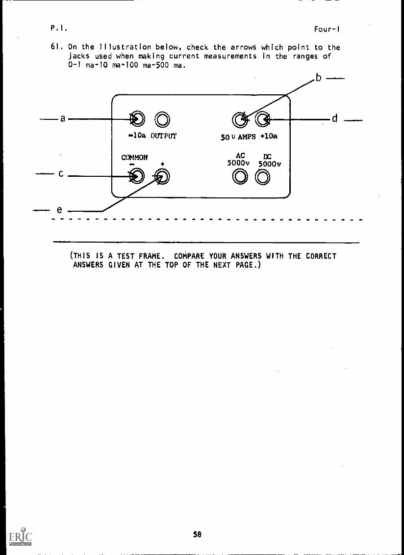
P.I. Four-I
61. On the illustration below, check the arrows which point to thejacks used when making current measurements in the ranges of0-1 ma-10 ma-100 ma-500 ma.
a
b
10a OUTPUT 50 U AMPS +10a
COMMON AC DC5000v 5000v
(THIS IS A TEST FRAME. COMPARE YOUR ANSWERS WITH THE CORRECTANSWERS GIVEN AT THE TOP OF THE NEXT PAGE.)
Se

P.I. Four-I
ANSWERS - TEST FRAME 61
c; e
IF ALL YOUR ANSWERS MATCH THE CORRECT ANSWERS, YOU MAY GO ON TO TESTFRAME 64. OTHERWISE, GO BACK TO FRAME 60 AND TAKE THE PROGRAMMEDSEQUENCE BEFORE TAKING TEST FRAME 61 AGAIN.
62. Using Practice Board 0-1, a 330 Q resistor, and one dry cell,construct a series circuit as shown below.
T1 T2nvvy
R13330
Ea 1.5v
*ro T7T8
Make sure switch is open.
(Go to next frame.)
59

P.I. Four-I
63. Following the steps below, measure current and record it in the
space provided.
1. Set function switch to +DC.2. Connect black test lead in the common (-) jack and the red
test lead in the (+) jack.
3. Set range switch to the highest ma setting (500 ma). Since
the exact current flow is still unknown, starting at thehighest ma range-switch setting can prevent damage to themeter.
4. Ensure switch is open, then break the circuit between T2 and17. and place the meter in series with the load. Remember,
polarity must be observed.
5. Energize circuit and observe the meter pointer. If pointer
deflects to the left, polarity is opposite to that which wasanticipated. De-energize the circuit and reverse meter leads
or turn the function switch to -DC. Energize the circuit
again.6. Read the current on the 0-50 DC scale. If necessary, move
the range switch to one of the other ma positions until youget as close to a mid-scale reading as possible. After youhave taken and recorded your reading, de-energize circuit andremove the test leads from the circuit.
Circuit current ma
(approximately 4.4 ma)
64. Construct the series circuit shown below. Then measure the
current and record it in the space provided.CK
PRO BROWN
T1 T2
Circuit current =
./1TR
(THIS IS A TEST FRAME. COMPARE YOUR ANSWER WITH THE CORRECTANSWER GIVEN AT THE TOP OF THE NEXT PAGE.)
60
P.I. Four-I
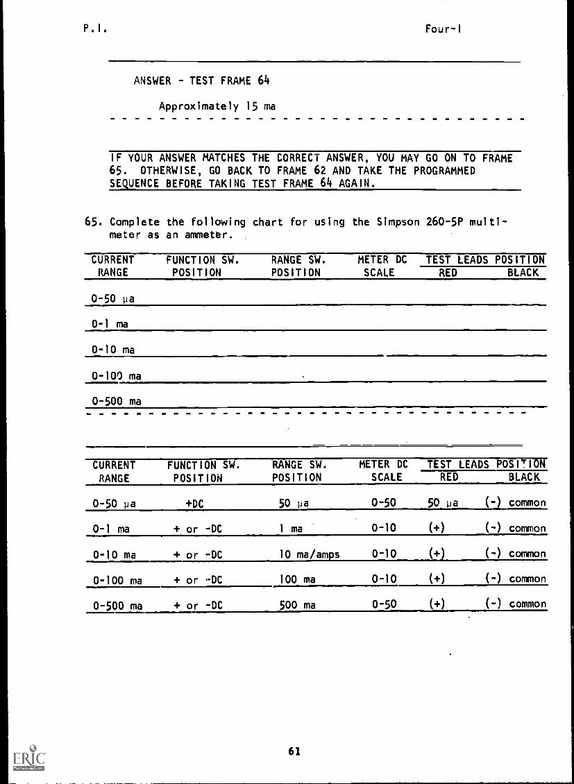
ANSWER - TEST FRAME 64
Approximately 15 ma
IF YOUR ANSWER MATCHES THE CORRECT ANSWER, YOU MAY GO ON TO FRAME65. OTHERWISE, GO BACK TO FRAME 62 AND TAKE THE PROGRAMMEDSEQUENCE BEFORE TAKING TEST FRAME 64 AGAIN.
65. Complete the following chart for using the Simpson 260-5P multi-meter as an ammeter.
CURRENT FUNCTION SW. RANGE SW. METER DC TEST LEADS POSITIONRANGE POSITION POSITION SCALE RED BLACK
0-50 pa
0-1 ma
0-10 ma
0-100 ma
0-500 ma
CURRENTRANGE
FUNCTION SW.
POSITION
RANGE SW.
POSITION
METER DCSCALE
TEST LEADS POSITIONRED BLACK
0-50 pa +DC 50 pa 0-50 50 pa (-) common
0-1 ma + or -DC 1 ma 0-10 (+) (-) common
0-10 ma + or -DC 10 ma/am s 0-10 (+) (-) common
0-100 ma + or -DC 100 ma 0-10 (+) (-) common
0-500 ma + or -DC 500 ma 0-50 (+) (-) common
61

P.I. Four-I
66. Listed below are the steps for measuring 0-10 amps DC. At this
time, you will not actually take current measurements using thisrange; however, it is important to understand how to set up the
meter to do so.
1. Place function switch at +DC.2. Connect black test lead in the -10 a jack and the red test
lead in the +10 a jack.3. Set the range switch on 10 a. (Note: This is also the common
setting for 10 ma.)4. De-energize circuit to be measured and place the meter in
series with load while observing proper polarity. Red test
lead to (+) black test lead to (-).
5. Energize circuit and observe meter pointer. If pointer de-flects to left, de-energize circuit and reverse the meter
leads. Energize circuit again. (Note: Function switch
has no effect on polarity in the 0-10 amp range.)6. Read the current directly on the 0-10 DC scale.
(Go to next frame.)
67. Refer to step 6 in frame 66. How much current would be flowing
in the meter below? amps.
(4.6 amps)
IF YOUR ANSWERS ARE CORRECT, YOU MAY TAKE THE PROGRESS CHECK, OR YOUMAY STUDY ANY OF THE OTHER RESOURCES LISTED. IF YOU TAKE THE PROGRESS
CHECK AND ANSWER ALL THE QUESTIONS CORRECTLY, GO ON TO THE NEXT LESSON.
IF NOT, STUDY ANY METHOD OF INSTRUCTION YOU WISH UNTIL YOU CAN ANSWER
ALL THE QUESTIONS CORRECTLY.
62
Summary
SUMMARY
LESSON I
Measuring Current in a Series Circuit
Four-I
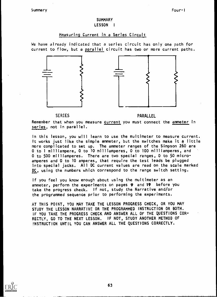
We have already indicated that a series circuit has only one path forcurrent to flow, but a parallel circuit has two or more current paths.
SERIES PARALLEL.
Remember that when you measure current you must connect the ammeter inseries, not in parallel.
In this lesson, you will learn to use the multimeter to measure current.It works just like the simple ammeter, but the switches make it a littlemore complicated to set up. The ammeter ranges of the Simpson 260 are0 to 1 milliampere, 0 to 10 milliamperes, 0 to 100 milliamperes, and0 to 500 milliamperes. There are two special ranges, 0 to 50 micro-amperes and 0 to 10 amperes, that require the test leads be pluggedinto special jacks. All DC current values are read on the scale markedDC, using the numbers which correspond to the range switch setting.
If you feel you know enough about using the multimeter as anammeter, perform the experiments on pages 9 and 19 before you
take the progress check. If not, study the Narrative and/orthe programmed sequence prior to performing the experiments.
AT THIS POINT, YOU MAY TAKE THE LESSON PROGRESS CHECK, OR YOU MAYSTUDY THE LESSON NARRATIVE OR THE PROGRAMMED INSTRUCTION OR BOTH.IF YOU TAKE THE PROGRESS CHECK AND ANSWER ALL OF THE QUESTIONS COR-RECTLY, GO TO THE NEXT LESSON. IF NOT, STUDY ANOTHER METHOD OF
INSTRUCTION UNTIL YOU CAN ANSWER ALL THE QUESTIONS CORRECTLY.
63

BASIC ELECTRICITY AND ELECTRONICS
INDIVIDUALIZED LEARNING SYSTEM
MODULE FOURLESSON II
Voltage in a Series Circuit
Study Booklet
BUREAU OF NAVAL PERSONNEL
January 1972
6Y/65
Overview Four-II
OVERVIEW
LESSON II
Voltage in a Series Circuit
In this lesson, you will study and learn about the following:
- difference in potential
- where potential difference exists in
a circuit
- voltage rise
- voltage drop
Each of the above topics will be discussed in the order listed.
As you proceed through this lesson, observe and follow directions
carefully.
BEFORE YOU START THIS LESSON, PREVIEW THE LIST OF STUDY RESOURCES
ON THE NEXT PAGE.
66

Study Resources Four-II
LIST OF STUDY RESOURCES
LESSON II
Voltage in a Series Circuit
To learn the material in this lesson, you have the option of
choosing, according to your experience and preferences, any or all
of the following:
STUDY BOOKLET:
Lesson Narrative
Programmed Instruction
Lesson Summary
ENRICHMENT MATERIAL:
NAVPERS 93400A-la "Basic Electricity, Direct Current."
Fundamentals of Electronics. Bureau of Naval Personnel.
Washington, D.C.: U.S. Government Printing Office, 1965.
You may study whatever learning materials you feel are necessary to
answer the questions in the Lesson Progress Check. All your answers
must be correct before you can go to Lesson III. Remember your in-
structor is available at all times for any assistance you may need.
YOU MAY NOW STUDY ANY OR ALL OF THE STUDY RESOURCES LISTED ABOVE. YOU
MAY TAKE THE PROGRESS CHECK AT ANY TIME.
67

Narrative Four-II
NARRATIVE
LESSON II
Voltage in a Series Circuit
Difference in Potential
You know you can measure current anywhere in a series circuitand the ammeter will read the same number of amps. However,
when measuring voltage, you will get a reading only betweenpoints where a difference in electrical potential exists.You recall that this potential difference is called voltage.This means voltage is measurable only between two points whereone point is more or less negative than the other point. Keep
in mind that if we say more negative, that also means lesspositive; or, if we say less negative, that also means morepositive.
Where Potential Difference Exists in a Circuit
A potential difference exists in a circuit:
1. Wherever energy is being applied to the circuit.This is referred to as the voltage rise or rise
in potential.
2. Wherever energy is being converted by the load. This is
called a fall in potential and is often referred
to as a voltage drop
Answer this question.
A
At what point in the above circuit does the
voltage drop take place?
Answer: At the load (B)
Voltage Rise
Recall how chemical action within a cell tends to causeelectrons to pile up at the outer terminal of a dry cell,
making this terminal negative. You also know that this
68
Narrative Four II
causes the center terminal to be deficient in electrons.
The center terminal now is less negative than the outer
terminal. When one point is more negative (-terminal)than another (+terminal), we say that a difference inpotential exists between these two points.
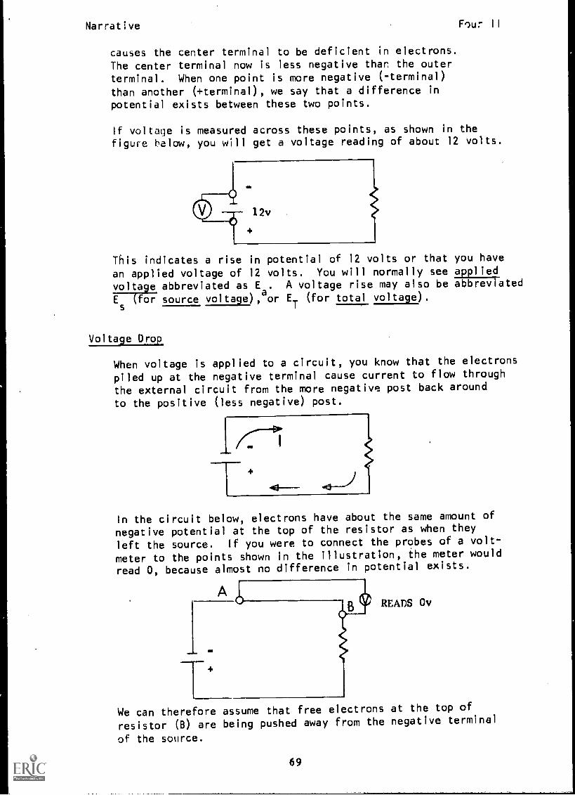
If voltage is measured across these points, as shown in thefigure below, you will get a voltage reading of about 12 volts.
This indicates a rise in potential of 12 volts or that you have
an applied voltage of 12 volts. You will normally see applied
voltage abbreviated as E. A voltage rise may also be abbreviated
Es
(for source voltage), or ET
(for total voltage).
Voltage Drop
When voltage is applied to a circuit, you know that the electrons
piled up at the negative terminal cause current to flow through
the external circuit from the more negative post back around
to the positive (less negative) post.
I
TIn the circuit below, electrons have about the same amount of
negative potential at the top of the resistor as when they
left the source. If you were to connect the probes of a volt-
meter to the points shown in the illustration, the meter would
read 0, because almost no difference in potential exists.
AREADS Ov
We can therefore assume that free electrons at the top of
resistor (B) are being pushed away from the negative terminal
of the source.
69
Narrative Four-II
A B
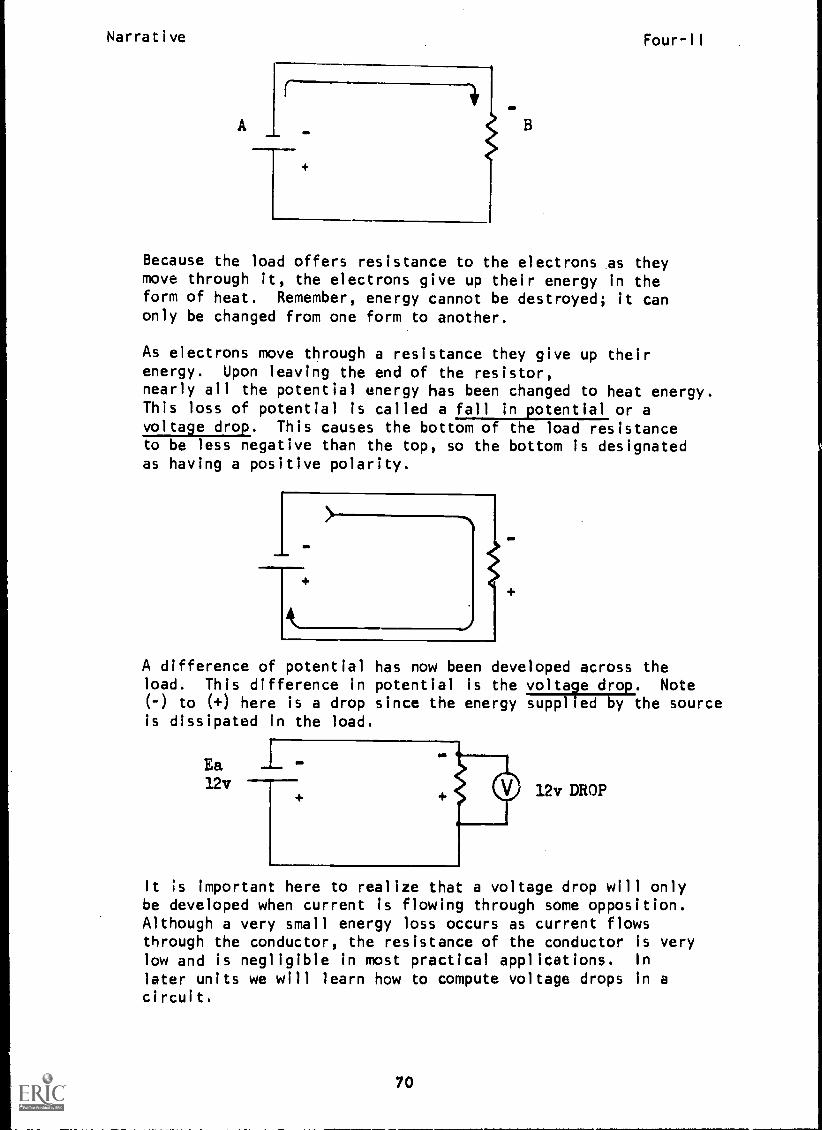
Because the load offers resistance to the electrons as theymove through it, the electrons give up their energy in theform of heat. Remember, energy cannot be destroyed; it canonly be changed from one form to another.
As electrons move through a resistance they give up theirenergy. Upon leaving the end of the resistor,nearly all the potential energy has been changed to heat energy.This loss of potential is called a fall in potential or avoltage drop. This causes the bottom of the load resistanceto be less negative than the top, so the bottom is designatedas having a positive polarity.
A difference of potential has now been developed across theload. This difference in potential is the voltage drop. Note(-) to (+) here is a drop since the energy supplied by the sourceis dissipated in the load.
Ea1.2v 12v DROP
It is important here to realize that a voltage drop will onlybe developed when current is flowing through some opposition.Although a very small energy loss occurs as current flowsthrough the conductor, the resistance of the conductor is verylow and is negligible in most practical applications. In
later units we will learn how to compute voltage drops in acircuit.
70

Narrative Four-11
Rules for Voltage in Series Circuits
Here are two "golden rules" that will prove to be invaluable.
This first rule is often called Kirchhoff's Voltage Law.
Rule 1. The total voltage drop in a series circuit will
always equal the applied voltage.
Answer this question.
Ea5ov
What is the value of applied voltage (Ea)?
a. 100 v
b. 0 v
c. 50 v
d. 25 v
Answer: c.
This rule holds true no matter how many resistors are in a
series circuit.
Note: We number the resistors R1, R2, and R3 to distinguish
each particular one. 12v
Ea12v
R1 6v 2 3v
Voltage drops, then, are designated as ER1, ER2, and ER3.
71
Narrative Four-II
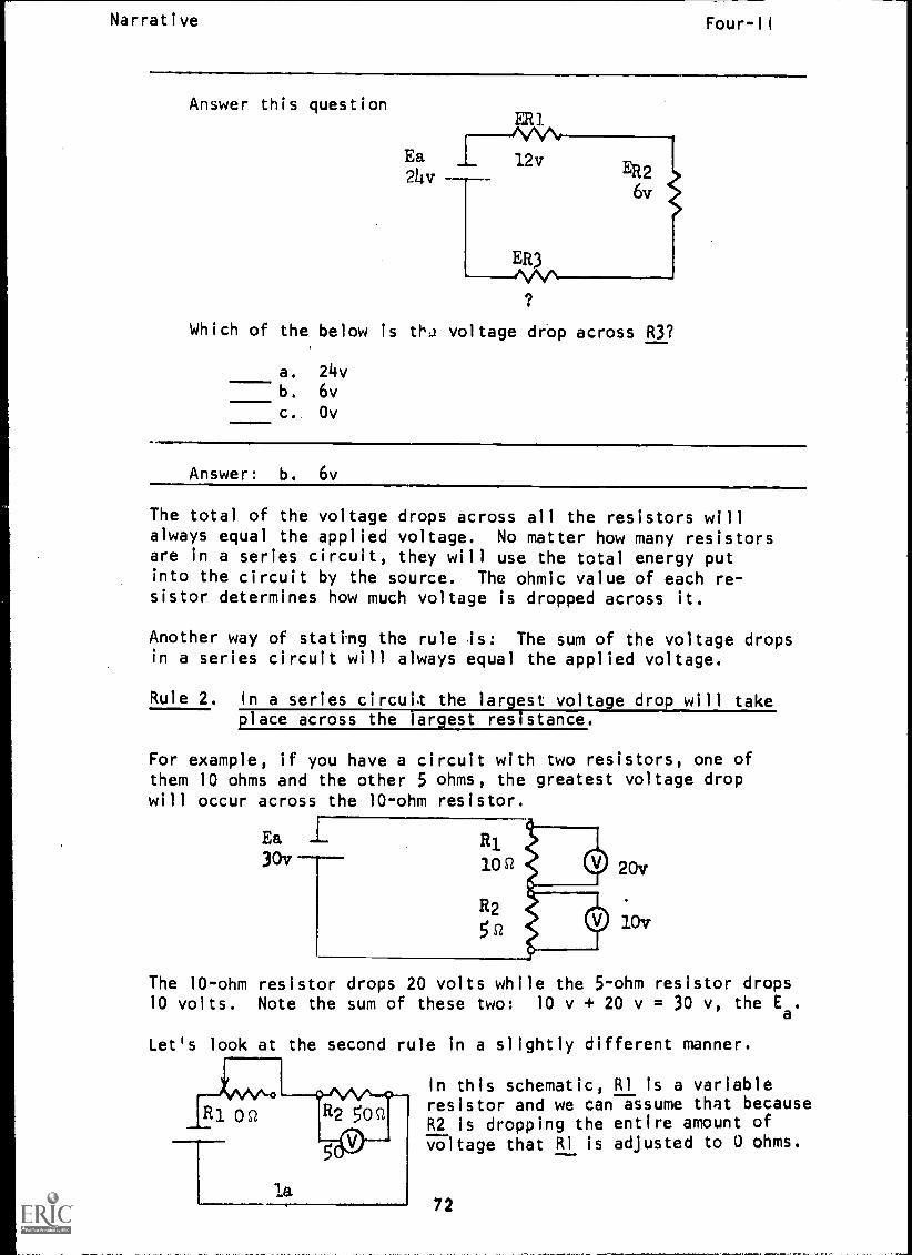
Answer this question
Ea24v
ER1MA,12v
ER26v
ER3
Which of the below is th2 voltage drop across R3?
a. 24vb. 6v
c. Ov
Answer: b. 6v
The total of the voltage drops across all the resistors willalways equal the applied voltage. No matter how many resistorsare in a series circuit, they will use the total energy putinto the circuit by the source. The ohmic value of each re-sistor determines how much voltage is dropped across it.
Another way of stating the rule is: The sum of the voltage dropsin a series circuit will always equal the applied voltage.
Rule 2. In a series circuit the largest voltage drop will takeplace across the largest resistance.
For example, if you have a circuit with two resistors, one ofthem 10 ohms and the other 5 ohms, the greatest voltage dropwill occur across the 10-ohm resistor.
Ea Ri30v 10Q
R2
5si
20v
10v
The 10-ohm resistor drops 20 volts while the 5-ohm resistor drops10 volts. Note the sum of these two: 10 v + 20 v = 30 v, the Ea.
Let's look at the second rule in a slightly different manner.
In this schematic, RI is a variableresistor and we can assume that becauseR2 is dropping the entire amount ofvoltage that RI is adjusted to 0 ohms.
72

Narrative Four-II
R150 5 1
Ea --
2
25v50v ----
G-1
.5o
Now if RI is set to the 50-ohm position,
notice that the voltage drop across R2decreases to 25 volts and the voltagedrop across RI increases to 25 volts.
This is an important concept to remember.Let's see if we can relate it to our two
voltage rules.
Rule 1 -Sum of voltage drops equals applied voltage. (It did in
both circuits.Notice that E is 50 volts in both cir-
cuits, and that if the voltageadrop across R2 decreases,
then the voltage drop across RI has to increase.
Rule 2 -Greatest volta9e drop will exist across largest resistance.
Notice as the value of RI increases, then the voltage drop
across it also increases. If R1 were increased above 50
ohms, then more voltage would be dropped across RI than
R2,
AT THIS POIN', YOU MAY TAKE THE PROGRESS CHECK, OR YOU MAY STUDY
ANY OF THE OTHER RESOURCES LISTED. IF YOU TAKE THE PROGRESS
CHECK AND ANSWER ALL OF THE QUESTIONS CORRECTLY, GO TO THE NEXT
LESSON. IF NOT, STUDY ANY METHOD OF INSTRUCTION YOU WISH UNTIL
YOU CAN ANSWER ALL THE QUESTIONS CORRECTLY.
73

P. I .
PROGRAMMED INSTRUCTIONLESSON II
Four-II
Voltage in a Series Circuit
TEST FRAMES ARE 20 AND 24. AS BEFORE, GO FIRST TO TEST FRAME 20AND SEE IF YOU CAN ANSWER ALL THE QUESTIONS THERE. FOLLOW THE DIREC-TIONS GIVEN AFTER THE TEST FRAME.
1. You know from the previous lesson that current can be measuredanywhere in a series circuit. Voltage, however, can be measuredonly between two points where one point is more (or less)negative than another point.
Voltage is measurable:
a. where a difference in potential exists in a circuit.b. anywhere in a series circuit.
(a) where a difference in otential exists in a circuit.
2. A difference in potential or potential difference can only existwhere electOcal energy is generated or where it is used by aload or resistance.
At what points in the circuit below can voltage be measured?
Id a
b
< I
a; b; c
74

P. I .Four-II
3. At what places in a circuit does a potential difference exist?
a. at the source which supplies electrical energy to the
circuit.b. at the conductor which carries electrical energy to the
load
c. at the load which receives and uses electrical energy
---TTat the source which supplies electrical energy to the circuit;and, c. at the load which receives and uses electrical energy.)
4. The potential difference is developed across the load by current
flowing through the load. Since we know that current in a circuit
outside the source flows from negative to positive, the point where
current enters the load device is labeled negative and the point
of departure is labeled positive.
Label the voltage drops with proper polarities.
4111111.6
001111111
011 ONO11M1100=1/
75

P.I. Four-II
5. Which circuit has a difference in potential across the load?
A
11VVV
(A)
6. In a circuit with an open switch, there will be some movement ofelectrons within the wires of the circuit. This movement willcontinue until the contact points of the open switch are at thesame electrical potential as the terminals of the source to whichthey are attached.
What potential difference exists across the switch in the circuitillustrated below?
or----4
12v
(The same as the source or 12v)
7. Between what points in the circuit below does a potentialdifference exist?
a. A and Bb. B and C
c. C and Dd. D and E1r.
b
ka. A and B; c. C and 0)
76

P. I .Four-II
8. A potential difference across a source is called a voltage rise
or rise in potential.
At what points in the circuit below does a voltage rise exist?
(a)
9. The place in the circuit where voltage is used by the load is
referred to as the voltage drop or fall in potential.
At what points in the circuit below does a voltage drop exist?
(a, c)
10. Match.
1. where energy is being used
by a load2. where voltage is being applied
'to the circuit at the source
3. rise in potential4. fall in potential
a. voltage drop
b. voltage rise
1. a; 2. b; 3. b; 4. a)
71

P. I . IEST COPY AVAILABLE Four-II
11. Study the schematic, then answer the questions below.
a
g
1. At what point does a voltage rise exist?2. At what points does a voltage drop exist?
(l. h, c) (
12. Match the letters on the schematic to the corresponding voltageconcepts.
I. voltage rise2. zero (0) difference in potential
3. voltage drop
----77ar (2. b and d) (3. c')
78

P. 1 . BEST COPY AVAILABLE Four-11
13. The voltage rise at the source is often abbreviated E (for
source voltage), Ea (for applied voltage), or ET (for totalvoltage).
Which circuits are correctly labeled?
b c. d.
1
SE Ea
(a, d)
14. A voltage drop is often abbreviated just E, but if there areseveral voltage drops in the circuit, each is labeled as ER1,ER2, etc., for differentiation.
Check the circuits that have the voltage drops correctly labeled.
B.
I
E ER2 ER1
(A, B)
15. Which circuit has the polarity of the voltage drops correctly labeled?
A.
ER2
B.
(A)
(REMEMBER: Polarities are labeled negative to positive across theload in the direction of current flow.)
79

P.I. Four-II
16. In a dry cell, chemical energy is converted and produces electricalpotential energy. When an electrical load is connected to a voltagesource (such as a dry cell) most of the electrical energy suppliedto the load is changed to heat (or other forms of energy) withinthe load. The change to a different form of energy causes theelectrical energy to decrease. This decrease in electrical energywithin the load is called voltage drop. For example, if the potentialenergy given to free electrons, as they are moved by the EMF withina cell, is 1.5V, then the same amount of energy, 1.5V must be givenup by free electrons as they pass through the load.
In the circuit below, how much voltage is dropped across theload?
V
(3 volts)
17. Regardless of the number of loads in a series circuit, the totalapplied voltage will be divided between the loads.
What is the voltage dropped (ER3) across R3 in the circuit?
a. 1.5 v
b. 14.5 v
c. 3.5 v
d. 1 v
L. Ea
14.51,
ER2 105v
ER12v
(d) 1 v
80

P.I. Four-II
18. In a series circuit, the sum of the voltage drops will alwaysequal the applied voltage. This is commonly called Kirchhoff's
Voltage Law.
What is the voltage drop (ER2) across R2 in the circuit below?
v.
Ea ER1 6:12v ---
itE2
6.-.
(6 v)
19. What is the applied voltage in the circuit below?
a. 12v
b. 3v
c. 6v
d. 18v
(d) 18v
81

P.I. Four-II
20. Study the schematic, then check the statements that are true.
ER2)4v
ER1 5v
Ea_ 9v
a. The voltage rise is equal to the sum of the voltage drops.
b. The total voltage dropped is 13 volts.
c. The voltage drop across RI is greater than the voltagedrop across R2.
d. The voltage rise at the source is 4 volts.
e. The total applied voltage is 18 volts.
f. The rise in potential is 9 volts.
g. The polarities indicated for both voltage drops arecorrect.
h. The polarity indicated for ER1
is correct.
(THIS IS A TEST FRAME. COMPARE YOUR ANSWERS WITH THE CORRECTANSWERS GIVEN AT THE TOP OF THE NEXT PAGE.)
82
P.I. Four-II
ANSWERS - TEST FRAME 20
a. The voltage rise is equal to the sum of the voltage drops.
c. The voltage drop across R1 is greater than thevoltage drop across R2.
f. The rise in potential is 9 volts.
g. The polarities indicated for both voltage drops arecorrect.
h. The polarity indicated for ER1 is correct.
IF ALL YOUR ANSWERS MATCH THE CORRECT ANSWERS, YOU MAY GO ON TOTEST FRAME 24. OTHERWISE, GO BACK TO FRAME 1 AND TAKE THE PRO-GRAMMED SEQUENCE BEFORE TAKING TEST FRAME 20 AGAIN.
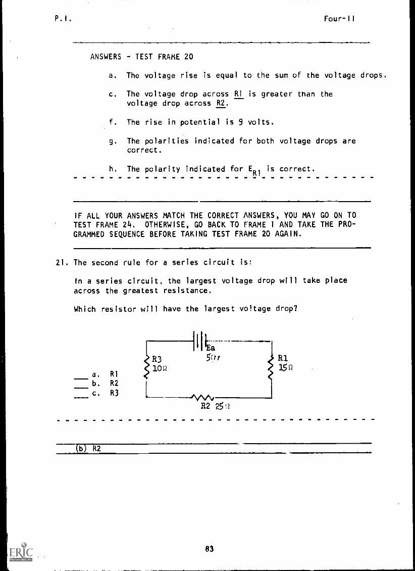
21. The second rule for a series circuit is
In a series circuit. the largest voltage drop will take place
across the greatest resistance.
Which resistor will have the largest voltage drop?
a. RI
b. R2
c. R3
IR31
5(tr00 3.5q
R2 25 Q
(b) R2
83

P.I. Four-II
22. Study the schematic below.
ER2^VVy
20v 10v
Which resistor has the largest ohmic value?
a. RI
b. R2
c. R3
En5v
(c) R3
23. The largest voltage drop in a series circuit will occur acrossthe:
a. resistor closest to the negative side of the source.b. resistor with the highest ohmic value.
c. load having the least resistance.
b resistor with the highest ohmic value.
24. Circle the resistor in each schematic that will have the largestvoltage drop.
A. B.
1
Eft2
5v
I IEa 15v
lostR3
0 s210c2
a 50v
MA,R2 15 SZ
25v
(THIS IS A TEST FRAME. COMPARE YOUR ANSWERS WITH 1HE CORRECTANSWERS GIVEN ON THE TOP OF THE NEXT PAGE.)
84

P.I. Four-II
ANSWERS - TEST FRAME 24
IF ANY OF YOUR ANSWERS IS INCORRECT, GO BACK TO FRAME 21 ANDTAKE THE PROGRAMMED SEQUENCE.
IF YOUR ANSWERS ARE CORRECT, YOU MAY TAKE THE PROGRESS CHECK, ORYOU MAY STUDY ANY OF THE OTHER RESOURCES LISTED. IF YOU TAKE THEPROGRESS CHECK AND ANSWER ALL THE QUESTIONS CORRECTLY, GO TO THE
NEXT LESSON. IF NOT, STUDY ANY METHOD OF INSTRUCTION YOU WISHUNTIL YOU CAN ANSWER ALL THE QUESTIONS CORRECTLY.
85

Summary Four-II
SUMMARYLESSON II
Voltage in a Series Circuit
Difference in potential, you will recall, is a difference in the
amount of charge between two points. This means that one of thepoints is more negative (or less positive) than the other.
A potential difference exists at the source where there is a risein potential, and at a load where there is a voltage drop. The
voltage rise at the source is often labeled Es (for source voltage),Ea
(for applied voltage), or Et
(for total or terminal voltage).A voltage drop is often abbreviated simply E, but if there areseveral voltage drops in the circuit, they may be marked E.. E
Kit ER2,etc., so each can be identified.
The total voltage rise in a circuit always equals the total voltagedrop in that circuit. In other words, all the energy given to thefree electrons by the source is given off as heat as they pass
through the load. This is the first rule for series circuit con-
ditions; it is actually an electronic equivalent of the principleof conservation of energy, and is known as Kirchhoff's Voltage Law.
Thus:
THE TOTAL VOLTAGE DROP IN A SERIES CIRCUIT WILL ALWAYS EQUALTHE APPLIED VOLTAGE.
Ea
20v
ER1
12v
ER2
What is the voltage drop (ER2)
across R2 in this circuit?
(Answer: 8 volts)
No matter how many resistors are in a series circuit, the totalapplied voltage will be divided among the resistors, and allthe voltage will be dropped. The resistance value of each resis-
tor determines what portion of the applied voltage will be dropped
by it. The resistor with the greatest resistance will get thelargest share of the voltage, the second-largest resistance will
get the second-largest voltage, and so on down the line to the
smallest resistance. The second rule for series circuit is:
IN A SERIES CIRCUIT, THE LARGEST VOLTAGE DROP WILL TAKEPLACE ACROSS THE LARGEST RESISTANCE.
If you place in series a variable resistor, a fixed resistor, and
a source, the voltage drop across the variable resistor will increase
A6

Summary Four-II
or decrease as th,! resistance goes up or down, and the fixed re-
sistor will always drop the rest of the applied voltage.
The diagram below illustrates the circuit at three different settings
of a variable resistor.
R2 /10C2 V
10v 15v
AT THIS POINT, YOU MAY TAKE THE LESSON PROGRESS CHECK, OR YOU MAY
STUDY THE LESSON NARRATIVE OR THE PROGRAMMED INSTRUCTION OR BOTH.
IF YOU TAKE THE PROGRESS CHECK AND ANSWER ALL OF THE QUESTIONS COR-
RECTLY, GO TO THE NEXT LESSON. IF NOT, STUDY ANOTHER METHOD OF
INSTRUCTION UNTIL YOU CAN ANSWER ALL THE QUESTIONS CORRECTLY.
87

NAVPERS 94558-4a
BASIC ELECTRICITY AND ELECTRONICS
INDIVIDUALIZED LEARNING SYSTEM
MODULE FOURLESSON III
Using the Multimeter as a Voltmeter
Study Booklet
BUREAU OF NAVAL PERSONNEL
January 1972
?r/89

Overview Four-III
OVERVIEW
LESSON III
Using the Multimeter as a Voltmeter
In this lesson you will study and learn about the following:
-meter connections
-interpreting the DC voltage scale
- practical measurement of DC voltage
(0-30v)
- measuring DC voltage (30-1000v)
- measuring AC voltage (0-1000v)
Each of the above topics will be discussed in the order listed.
As you proceed through this lesson, observe and follow directions
carefully.
BEFORE YOU START THIS LESSON, PREVIEW THE LIST OF STUDY RESOURCES
ON THE NEXT PAGE.
90

Study Resources Four-III
LIST OF STUDY RESOURCES
LESSON III
Using the Multimeter as a Voltmeter
To learn the material in this lesson, you have the option of choosing,
according to your experience and preferences, any or all of the following:
STUDY BOOKLET:
Lesson Narrative
Programmed Instruction
Lesson Summary
ENRICHMENT MATERIAL:
NAVPERS 93400A -la "Basic Electricity, Direct Current."
Fundamentals of Electronics. Bureau of Naval Personnel.
Washington, D.C.: U.S. Government Printing Office, 1965.
AUDIO-VISUAL:
Sound/Slide Presentation - "Measuring Voltage With a Multimeter."
YOU MAY NOW STUDY ANY OR ALL OF THE RESOURCES LISTED ABOVE. YOU MAY
TAKE THE PROGRESS CHECK AT ANY TIME.
91
Narrative Four-Ill
NARRATIVELESSON III
Using the Multimeter as a Voltmeter
You have learned to use the multimeter to measure resistanceand direct current. We are now going to use it to take DC andAC voltage readings. The settings and connections to usethe multimeter as a voltmeter will be different than the onesused when using it as an ammeter or ohmmeter.
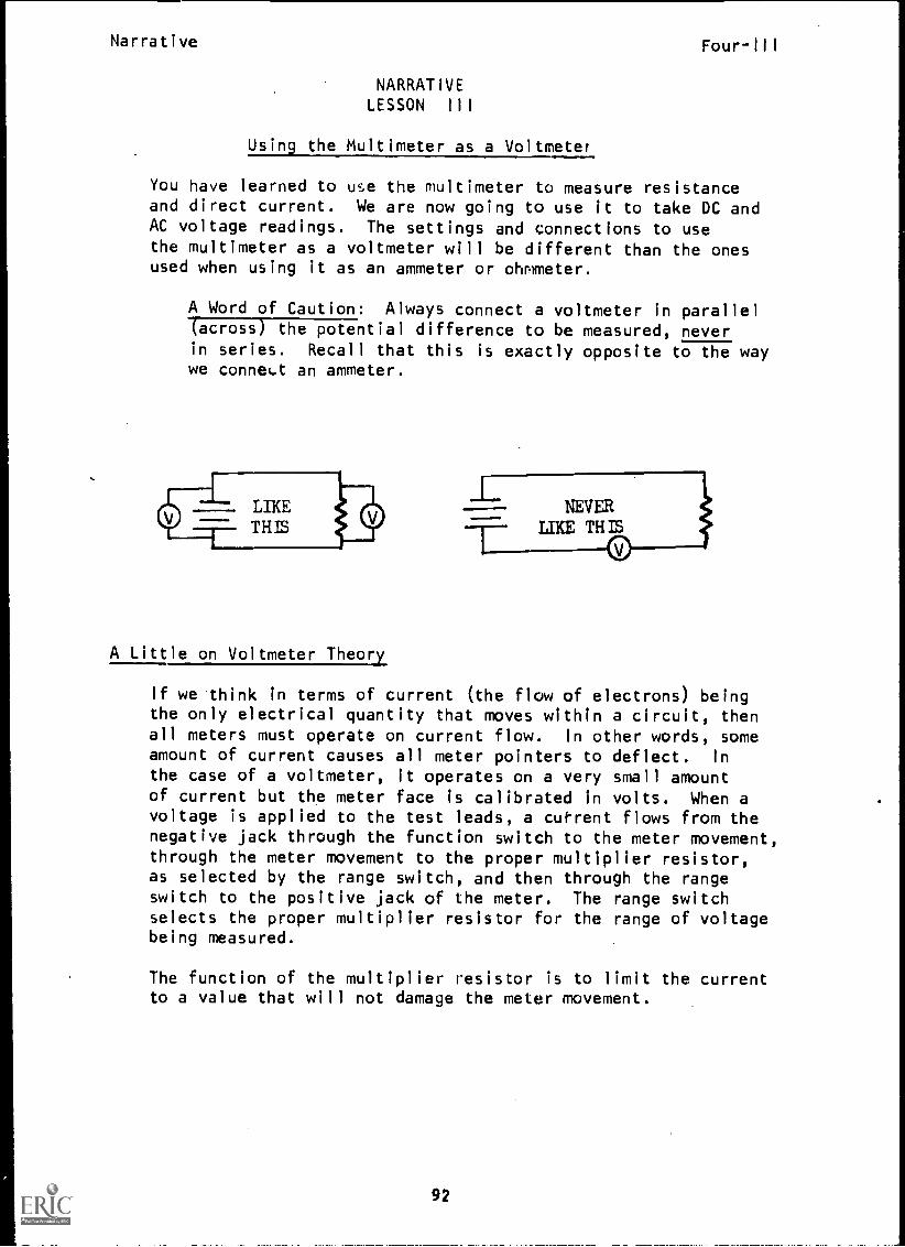
A Word of Caution: Always connect a voltmeter in parallel(across) the potential difference to be measured, neverin series. Recall that this is exactly opposite to the waywe connect an ammeter.
A Little on Voltmeter Theory
If we think in terms of current (the flow of electrons) beingthe only electrical quantity that moves within a circuit, thenall meters must operate on current flow. In other words, someamount of current causes all meter pointers to deflect. In
the case of a voltmeter, it operates on a very small amountof current but the meter face is calibrated in volts. When avoltage is applied to the test leads, a cur-rent flows from thenegative jack through the function switch to the meter movement,through the meter movement to the proper multiplier resistor,as selected by the range switch, and then through the rangeswitch to the positive jack of the meter. The range switchselects the proper multiplier resistor for the range of voltagebeing measured.
The function of the multiplier resistor is to limit the currentto a value that will not damage the meter movement.
92

Narrative BEST COPY AVAILABLE Four-III
Interpreting the DC Voltage Scale
You will use the black arc labeled DC (second from the top) for
all DC voltage measurements. Recall that this is the same arc
(scale) we used to read current.
The three rows of numbers directly under the DC arc will be
used to measure values of voltage. The row used will depend
on the position of the range selector. If the range switch
is set on 2.5 v, simply put an imaginary decimal point before
the last two digits on the 250 row. You are actually dividing
by 100. If the range switch is set on 10, you read the 10 v
scale directly; if set at 50, you read the 50 v scale directly.
When the setting is 250, you read the 250 v scale directly.
If the range switch is in the 1000 v position, use the 0-10
scale and add two zeros to the indicated value. Here you are
multiplying by 100.
(See illustration on next page.)
93

NarrativeBEST COPY AVAILABLE
le 15 10
0v,45 ,..1.-
MO ISD4 20 SO
e `CO ". A 6
p
10V'1
t,C) e4c)
4°.$1.111,4
,
VOLT OHM M14 ,..0 .I vl tse. .41, 46 YMwf awe %ft o I ,VAS
l0
WOW ADO tt4i V IIA144 Ale *I
Ttlt 'AIM, MD OS
In this illustration, the meter reads 2 volts.
Measuring DC Voltage (0-30 Volts)
Four-III
1. Using Practice Board 0-1, a 10 Q resistor, and four drycells, construct a series circuit as shown below.
T1 T2, ese.".^AeZ1 T14
1.5v R1.10
..=1".. 1.5v1.5v1arse 1.5v
.""VT8 T7
R2=u-50
94
Narrative Four-III
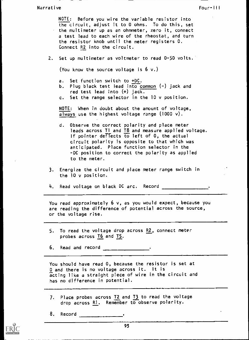
NOTE: Before you wire the variable resistor intothe circuit, adjust it to 0 ohms. To do this, setthe multimeter up as an ohmmeter, zero it, connecta test lead to each wire of the rheostat, and turnthe resistor knob until the meter registers O.Connect R2 into the circuit.
2. Set up multimeter as voltmeter to read 0-50 volts.
(You know the source voltage is 6 v.)
a. Set function switch to +DC.b. Plug black test lead into common (-) jack and
red test lead into (+) jack.
c. Set the range selector in the 10 v position.
NOTE: When in doubt about the amount of voltage,always use the highest voltage range (1000 v).
d. Observe the correct polarity and place meterleads across Tl and T8 and measure applied voltage.If pointer deflects to left of 0, the actualcircuit polarity is opposite to that which wasanticipated. Place function selector in the-DC position to correct the polarity as applied
to the meter.
3. Energize the circuit and place meter range switch inthe 10 v position.
4. Read voltage on black DC arc. Record
You read approximately 6 v, as you would expect, because youare reading the difference of potential across the source,or the voltage rise.
5. To read the voltage drop across R2, connect meterprobes across T6 and 15.
6. Read and record
You should have read 0, because the resistor is set at0 and there is no voltage across it. It is
acting like a straight piece of wire in the circuit and
has no difference in potential.
7. Place probes across T2 and T3 to read the voltage
drop across Rl. Remember to observe polarity.
8. Record
95

Narrative Four-III
The voltage drop across Rl, which we designate as ER1'
is
approximately 6 v is the amount of voltage applied to thecircuit. All of the applied voltage is being droppedacross Rl because we consider it as the only oppositionto current in the circuit.
Now let's see what happens when we add resistance to thecircuit by varying R2.
1. Connect the probe clips across R2.
2. Slowly turn the knob on the variable resistor toincrease resistance.
3. Observe the meter.
4. Turn the knob until R2 is at full resistance (as faras knob will turn).
5. What is ER2
?
You read that ER2
is approximately 5 v when R2 is atits maximum resistance value and is it series with RI.
As R2 is now about 50 St and RI is 10 Q, this demonstratesthat the greatest voltage drop takes place across thegreatest resistance.
6. Leaving R2 at maximum 50 Q, connect probes across RI.
7. ER1 equals
E then is approximately 1 volt, demonstrating that the sumor the voltage drop equals the applied voltage. Note thatthese values (5 v and 1 v) are not exact because we needto allow for meter and circuit tolerances.
8. Reconnect probes across R2 and vary resistance againuntil you read approximately 3 v on the meter.
9. Then read ER1
to see if you also read approximately3 v there.
You have observed that as the value of R2 increases,ER2
increases and ER1
decreases. The reverse is also
true. As R2 decreases, ERR decreases and ER increases
so that the sum of the voltage drops equals the applied
voltage.
96
Narrative Four-III
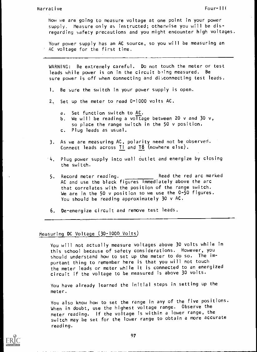
Now we are going to measure voltage at one point in your power
supply. Measure only as instructed; otherwise you will be dis-regarding safety precautions and you might encounter high voltages.
Your power supply has an AC source, so you will be measuring anAC voltage for the first time.
WARNING: Be extremely careful. Do not touch the meter or test
leads while power is on in the circuit being measured. Be
sure power is off when connecting and disconnecting test leads.
I. Be sure the switch in your power supply is open.
2. Set up the meter to read 0-1000 volts AC.
a. Set function switch to AC.b. We will be reading a voltage between 20 v and 30 v,
so place the range switch in the 50 v position.c. Plug leads as usual.
3. As we are measuring AC, polarity need not be observed.Connect leads across Tl and T8 (nowhere else).
4. Plug power supply into wall Outlet and energize by closingthe switch.
5. Record meter reading. Read the red arc marked
AC and use the black figures immediately above the arcthat correlates with the position of the range switch.We are in the 50 v position so we use the 0-50 figures.
You should be reading approximately 30 v AC.
6. De-energize circuit and remove test leads.
Measuring DC Voltage (30-1000 Volts)
You will not actually measure voltages above 30 volts while in
this school because of safety considerations. However, you
should understand how to set up the meter to do so. The im-
portant thing to remember here is that you will not touch
the meter leads or meter while it is connected to an energized
circuit if the voltage to be measured is above 30 volts.
You have already learned the initial steps in setting up the
meter.
You also know how to set the range in any of the five positions.
When in doubt, use the highest voltage range. Observe the
meter reading. If the voltage is within a lower range, the
switch may be set for the lower range to obtain a more accurate
reading.
97

Narrative Four-III
Note: De-energize the circuit prior to turning range switch.
When you energize the circuit to be tested, if the pointerdeflects to the left of 0, the circuit polarity isopposite the anticipated polarity. Turn the circuit power off.Set the function switch at -DC, and turn the power on. Thiswill correct the polarity as applied to the meter. Read thevoltage on the black arc marked DC. Turn the circuit poweroff before disconnecting leads.
Measuring AC Voltage (30-1000 volts)
Warning: Here again if the voltage to be measured is above 30volts, do not touch meter or its leads while the are connectedto the energized circuit. The c rcuit must be de-energ zed w enmaking meter connections.
AT THIS POINT, YOU MAY TAKE THE PROGRESS CHECK, OR YOU MAY STUDYANY OF THE OTHER RESOURCES LISTED. IF YOU TAKE THE PROGRESS CHECKAND ANSWER ALL OF THE QUESTIONS CORRECTLY, YOU HAVE MASTERED THEMATERIAL AND ARE READY TO TAKE THE MODULE TEST. SEE YOUR INSTRUCTOR.
IF YOU DECIDE NOT TO TAKE THE PROGRESS CHECK AT THIS TIME, OR IFYOU MISSED ONE OR MORE QUESTIONS, STUDY ANY METHOD OF INSTRUCTIONYOU WISH UNTIL YOU HAVE ANSWERED ALL THE PROGRESS CHECK QUESTIONSCORRECTLY. THEN SEE YOUR INSTRUCTOR AND ASK TO TAKE THE MODULETEST.
98
P.I. Four-III
PROGRAMMED INSTRUCTIONLESSON III
Using the Multimeter as a Voltmeter
TEST FRAMES ARE 7, 14, 31, 34, 43, 44, 52, AND 56. AS BEFORE,GO FIRST TO TEST FRAME 7 AND SEE IF YOU CAN ANSWER ALL THE QUESTIONSTHERE. FOLLOW THE DIRECTIONS GIVEN AFTER THE TEST FRAME.
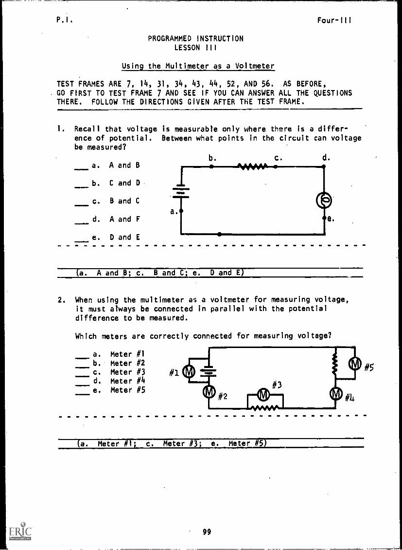
1. Recall that voltage is measurable only where there is a differ-ence of potential. Between what points in the circuit can voltagebe measured?
a. A and B
b. C and D
c. B and C
d. A and F
e. D and E
b. C. d.
(a. A and B; c. B and C; e. D and E)
2. When using the multimeter as a voltmeter for measuring voltage,it must always be connected in parallel with the potentialdifference to be measured.
Which meters are correctly connected for measuring voltage?
a. Meter #1
b. Meter #2c. Meter #3d. Meter #4e. Meter #5
#1
(a. Meter #1' c. Meter #3' e. Meter #5)

P.I. Four-111
3. The Simpson 260-5P multimeter is capable of measuring eitherAC or DC voltages.
Which control on the multimeter determines whether AC or DCvoltage values are to be measured?
a. 0 ohmsb. function switch.
(b) function switch
4. When measuring DC voltage,, polarity must be observe°.
The negative probe of the meter must be connected to a point ofnegative polarity and the positive probe of the meter to a pointof positive polarity.
Which schematic shows the multimeter correctly installed forDC voltage measurements?
A
I I-(C)
5. Which voltmeter is correctly installed for measuring DC voltage?
a. Voltmeter #1b. Voltmeter #2
c. Voltmeter #3
#1
(1)1 Voltmeter #2
100

P.I. , Four-III
6. When used to measure AC voltage, meter polarity does not haveto be observed. Which schematic shows the meter correctly
installed for AC voltage measurements?
A B
(A, B - both are correct)
7. Match:
2.
3 VOLTAGESOURCE
4. 10,
a. AC voltage meterconnection
b. DC voltage meterconnection
c. incorrect voltmeterconnection (AC 6 DC)
(THIS IS A TEST FRAME. COMPARE YOUR ANSWERS WITH THE CORRECT
ANSWERS GIVEN AT THE TOP OF THE NEXT PAGE.)
101
P. I . MUM AVAILABLE Four-Ill
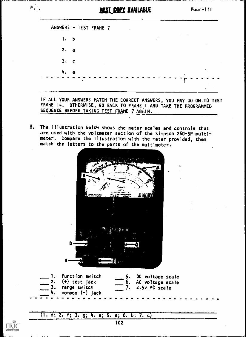
ANSWERS - TEST FRAME 7
1. b
2. a
3.
4. a
IF ALL YOUR ANSWERS MATCH THE CORRECT ANSWERS, YOU MAY GO ONTO TESTFRAME 14. OTHERWISE, GO BACK TO FRAME I ANU TAKE THE PROGRAMMEDSEQUENCE BEFORE TAKING TEST FRAME 7 AGAIN.
8. The illustration below shows the meter scales and controls thatare used with the voltmeter section of the Simpson 260-5P multi-meter. Compare the illustration with the meter provided, thenmatch the letters to the parts of the multimeter.
D
E
1. function switch2. ( +) test jack
3. range switch4. common (-) jack
c16}111n.
OLU414 .Ml ..1
DC voltage scaleAC voltage scale2.5v AC scale
102
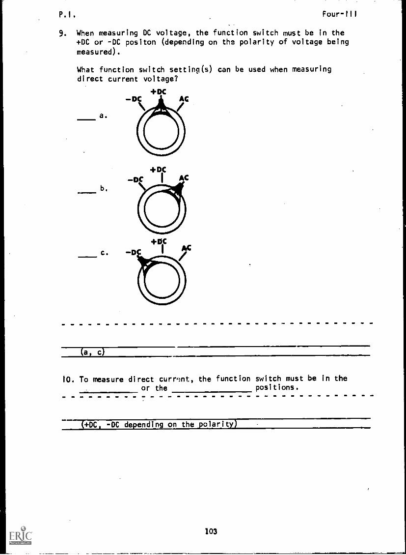
P.I. Four-III
9. When measuring DC voltage, the function switch must be in the+DC or -DC positon (depending on the polarity of voltage being
measured).
What function switch setting(s) can be used when measuringdirect current voltage?
+DC--DC AC
a.
b.
c.
+DiC
-DC I AC
(a, c)
10. To measure direct current, the function switch must be in theor the positions.
(*DC -DC depending on the 'olarit
103

P.I.IEST COPY AVAILABLE
11. When setting up the multimeter to read DC voltage, the functionswitch is normally placed in the +DC position. Remember DCvoltage measurements require that polarity be observed.
Four-111
Which drawing shows the multimeter correctly connected formeasuring DC voltage?
A.
B.
104

P.I.
12. The pointer of the multimeter when not measuring current or voltage,
should rest at the "0" position. When the meter is properly connected
to measure current or voltage, the proper polarity must be observed.
The pointer will then move to the right.
Which pointer position indicates proper polarity of the meter
connection?
A.
(A, C)
B.
0
105
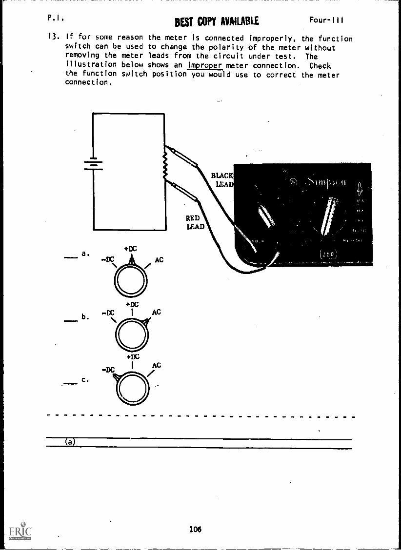
P.I.BEST COPY AVAILABLE Four-Ill
13. If for some reason the meter is connected improperly, the functionswitch can be used to change the polarity of the meter withoutremoving the meter leads from the circuit under test. Theillustration below shows an improper meter connection. Checkthe function switch position you would use to correct the meterconnection.
b.
c.
+DC.DC I AC
(a)
106
P.I. Four-III
14. Check the statements that are true.
a. When measuring voltage, the function switch mustalways be in the +DC position.
b. When reading DC voltage, polarity must be observed.
c. When measuring DC voltage, correct meter connectionwill cause pointer deflection to the left of zero.
d. Meter polarity can be changed by moving the functionswitch to either +DC or -DC.
e. Meter polarity can only be changed by removing thetest leads from the circuit and reversing them.
(THIS IS A TEST FRAME. COMPARE YOUR ANSWERS WITH THECORRECT ANSWERS GIVEN AT THE TOP OF THE NEXT PAGE.)
107
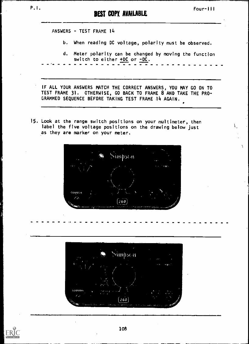
P.I. Four-111
BEST COPY AVAILABLE
ANSWERS - TEST FRAME 14
b. When reading DC voltage, polarity must be observed.
d. Meter polarity can be changed by moving the functionswitch to either +DC or -DC.
IF ALL YOUR ANSWERS MATCH THE CORRECT ANSWERS, YOU MAY GO ON TOTEST FRAME 31. OTHERWISE, GO BACK TO FRAME 8 AND TAKE THE PRO-GRAMMED SEQUENCE BEFORE TAKING TEST FRAME 14 AGAIN.
15. Look at the range switch positions on your multimeter, thenlabel the five voltage positions on the drawing below justas they are marker on your meter.
108

P.1. BEST COP1 AVAILABLE
16. Each voltage range-switch marking represents the maximumvoltage that the multimeter. is capable of measuring when in
that position. For example if the range switch is set to
50 v, this means that the voltage range is 0-50 v; if the
range switch is set to 10 v, the voltage range would be 0-10 v.
Four-III
What would the voltage range be if the range switch were set
to 250 v?
a. 250-1000 vb. 0-250 vc. 10-250 v
(b) 0-250 v
17. Look at the voltage range swPch positions again, then list thevoltage ranges the meter is designed to measure. (Any order.)
a.
b.
c.
d.
e.
1
(0-2.5 v; 0-10 v; 0-50 v; 0-250 v; 0-1000 v/5000 v)
18. The meter scale used for measuring DC voltage is the black arcthat is labeled DC (second from top). Locate the DC scale on
your multimeter, then check the arrow that points to the DC
scale in the illustration.
111.00 Pitt IM VIA IV $ HMSOH MIUMC CO CHKM40.111.
20 15 10
40. "p
do V
MO 01 POIVIS MIS111 IrAtt HO OHMS
260stun Sr
OVERLOAD PROTECTEDVOLT OHM twill UAMMETElt*coop nftv OC 9.000 ts/V AC
M V 1041031. ADO 11 01Mt V MANG'. A00 11 DI
110V NANO. ADO 11 01
A
C
0
{b)
109

P. I . Four-111
19. Look at the DC scale on your multimeter again. Notice that thereare three rows of numbers under the black arc calibrated 0-250,0-50, and 0-10. All three of these meter scales are used forDC voltage measurements. The position of the range switch (2.5 v,10 v, 50 v, 250 v, 1000/5000 v) will determine which DC meterscale to use.
Which diagram correctly identifies the numbers used for measure-ing DC voltage?
A. B.
(A)
20. When the range switch is in the 2.5 v position, use the 0-250 DCscale and d;v1de the indicated value by 100. What would thevoltage reading be for the illustration?
a. 1.25 voltsb. 12.5 volts
c. 25 voltsd. 250 volts
rrrrr-r-tOO20A
(a) 1.25 v
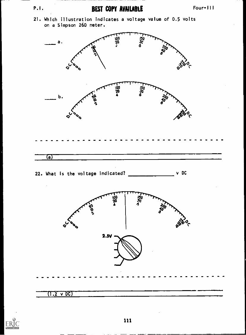
P.I. BEST COPY AVAILABLE Four-111
21. Which illustration indicates a voltage value of 0.5 volts
on a Simpson 260 meter.
a.
b.
(a)
22. What is the voltage indicated? v DC
ti
2.5V
20 30A 6
OP'
1.2 v DC
111

P.I. BEST C011, AVAII,ABLk Four-III
23. If the range switch is in the 1000 v position, use the 0-10 DCscale and multiply by 100.
What would the voltage reading be for the illustration?
i-r*Trrr-too l
20 I 3oA 6
tY 'Jcb
The voltage indicated is v DC
O
(540 v DC)
24, Which illustration could indicate a voltage value of 460volts on the Simpson 260?
too iso
a. 20 30
ti
4
b.
Id 0,,g' "(4
IT
It JrA
40
off' "sc.
( b)
112
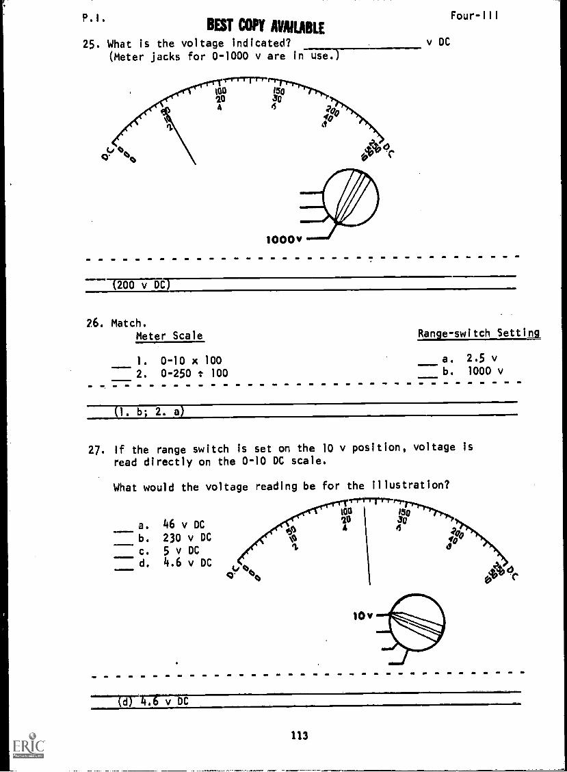
. I .
BEST COPY AVAILABLE
25. What is the voltage indicated?(Meter jacks for 0-1000 v are in use.)
tdcr OHO
m0 fSQ20 30
4
v DC
Four-III
200 v DC )
26. Match.Meter Scale Range-switch Setting
1. 0-10 x 1002. 0-250 t 100
a. 2.5 vb. 1000 v
(1. b. 2. a)
27. If the range switch is set on the 10 v position, voltage is
read directly on the 0-10 DC scale.
What would the voltage reading be for the illustration?
t00
20630
a. 46 v DC
b. 230 v DC
c . 5 v DCd. 4.6 v DC
...1
110=1111.0
0'tr tots
ti
10
(d 4.6vDC
113

P.I. Four-III
28. If the range switch is set on the 50 v position, voltage isread directly on the 0-50 DC scale.
What would the voltage reading be for the illustration?
=111.111
a. 130 v DCb. 26 v DC
c. 5.2 v DCd. 35 v DC
1 rrry-mirrp.,
20 350°IGO
4 40 10w
50v
(b) 26 v DC
29. If the range switch is set on the 250 v position, voltage isread directly on the 0-250 DC scale.
What would be the voltage reading for the illustration.
1'T 1 rrrr.
a. 135 v DC 20 57.161.1.7..?./.4PWO
30b. 5.4 v DC yo A IFC. 270 v DC 0
1d. 54 v DC
t,0' '1%
(a) 131.v DC
114

P.I. Four-Ill
30. Match the meter DC scale to the range switch position. Meter
leads are connected to common (-) and (+) jacks in every case.
Range Switch Position Meter DC Scale
I. 2.5 v a. 0-50
2. 10 v b. 0-10
3. 50 v c. 0-250
4. 250 v5. 1000/5000 v
(1. c; 2. b; 3. a; 4. c; 5. b/a)
31. Interpret the meter DC scale below by matching the indicatedvoltage to the range switch position.
Lbe,'"ot,
1-rr-r-Trr100 rIal-1"7.ID 304 6 2.
100 0I.
Range Switch Position DC Voltage
1. 10 v a. 540 volts
2. 50 v b. 135 volts
3. 2.5 v c. 27 volts
4. 250 v d. 1.35 volts
5. 1000 v e. 5.4 volts001111MMIMII.
(9449 .f?c
(THIS IS A TEST FRAME. COMPARE YOUR ANSWERS WITH THE CORRECT
ANSWERS GIVEN ON THE TOP OF THE NEXT PAGE.)
115

P. I .IIESI COP! AVAILABLE
Four-III
ANSWERS - TEST FRAME 31
1.
2.
3. d
4. b
5. a
IF ALL YOUR ANSWERS MATCH THE CORRECT ANSWERS, YOU MAY GO ON TO TESTFRAME 34. OTHERWISE, GO BACK TO FRAME 15 AND TAKE THE PROGRAMMEDSEQUENCE BEFORE TAKING TEST FRAME 31 AGAIN.
32. When using the multimeter to read DC voltage, the common (-)test jack and the (+) test jack are used.
Using the illustration below, locate on your multimeter the common(-) jack and (+) jack.
COMMON POSITIVE ,
Go to next frame.
116

BEST COP Four-III
33. On the illustration below, check the arrows which point to thejacks used when making DC voltage measurements.
C"
(c, e)
117
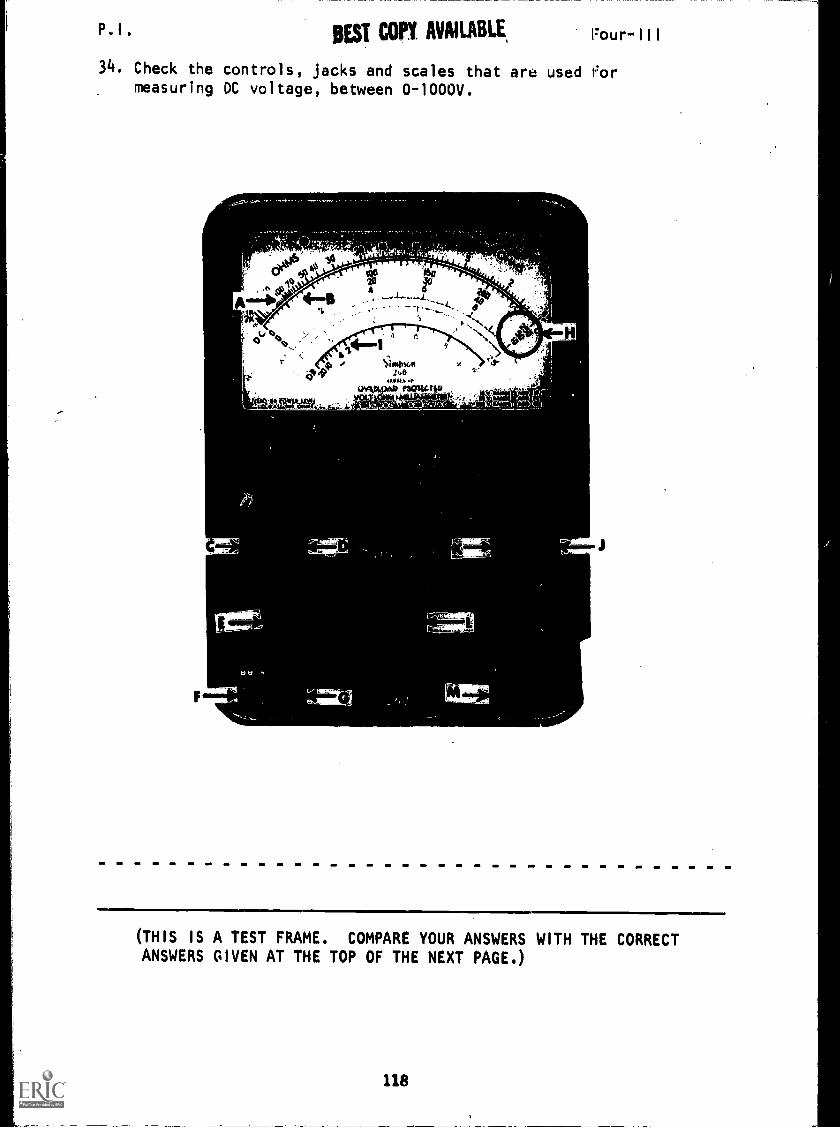
P.I . BEST COPY AVAILABLE, Four-III
34. Check the controls, jacks and scales that are used 1.'0rmeasuring DC voltage, between 0-1000V.
F
.
de2 0 too oso'1% 20 30(.04 A 6
A+ 4-1I - -'-":"7-:--L.:-.---4...
311V 1 .._
. 0
f 0 c,I c IA
# ciN*141t
4. 444 P.0ilow.....
A
K
L
(THIS IS A TEST FRAME. COMPARE YOUR ANSWERS WITH THE CORRECTANSWERS GIVEN AT THE TOP OF THE NEXT PAGE.)
118
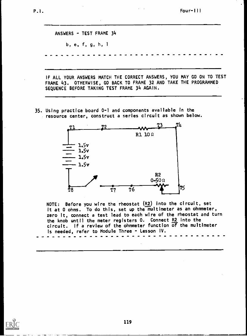
P.I. Four-III
ANSWERS - TEST FRAME 34
b, e, f, g, h, 1
IF ALL YOUR ANSWERS MATCH THE CORRECT ANSWERS, YOU MAY GO ON TO TEST
FRAME 43. OTHERWISE, GO BACK TO FRAME 32 AND TAKE THE PROGRAMMEDSEQUENCE BEFORE TAXING TEST FRAME 34 AGAIN.
35. Using practice board 0-1 and components available in theresource center, construct a series circuit as shown below.
MAr----303T4
R1 10 St
Ti ;2
1.5vL5v1.5v1.5v
I /IFT8 T7 T6
0-50 St
-410-
R2
TS
NOTE: Before you wire the rheostat (R2) into the circuit, set
it at 0 ohms. To do this, set up the multimeter as an ohmmeter,
zero it, connect a test lead to each wire of the rheostat and turn
the knob until the meter registers O. Connect R2 into the
circuit. If a review of the ohmmeter function UT the multimeter
is needed, refer to Module Three - Lesson IV.
119

P.1.BEST COPY AVAILABLE Four-111
36. Listed below are the proper steps for setting up the multi-meter for measuring DC voltage.
1. Set the function switch at +DC.
2. Plug the black test lead into the common (-)jack and the red test lead into thiTinack.
3. Set the range switch at the 1000/5000 v position.(Always start with the highest voltage range settingsand then reduce as necessary to obtain a reading nearmidscale.)
Following the steps listed above, set up your multimeter, thencheck your meter set up against this illustration.
black load 4401_
(Go to next frame.)
120

P.I. Four-III
37. Energize the series circuit you have constructed, and observing
correct polarity (red test lead to positive side of the source
and black test lead to negative side), place the meter leads
across T1 and T8. ri T2 T3
--1--1.5v
1.5v1.5v
1.5v
. -A0.50Q
R2
r-m T7 T6
If the meter pointer deflects to left of "0", the polarity is
opposite to that which was anticipated. Place the function
switch in the -DC position. This will correct the polarity as
applied to the meter.
R110si
MT to next frame)
38. Decrease the range switch setting until you get a reading near
midscale. Be careful not to turn to a range setting lower than
the voltage present. At what range-switch position do you get
the best midscale reading?
(10 v position)
39. Read the voltage on the black DC 0-10 scale. What is the
value of the applied voltage (Ea
) in the circuit?
volts.
(Ea= 6 v approximate)
40. Place the test probes across T5 and T6. What is the voltage
drop across R2 (variable resistor)?
Or- = 0 volts) Because the res stor is set at 0, there w be
no2voltage dropped across it. The resistor is acting like a piece
of wire in the circuit and has no difference in potential.
121

P.I. Four-III
41. Next place your probes across RI (between T2 and T3). What isthe voltage drop across R11 v.
ER v approximate Recall that the sum of the voltage dropsmust equal the applied voltage (E ); and in a series circuit, thegreatest voltage drop takes placeaacross the greatest resistance.In this case, ER1 (6 v) + E
R2(0 v) = E
a(6 v).
42. For your next measurement, connect the probe clips across R1and increase the resistance of R2 by turning the knob. Observethe meter. The voltage drop across R1 should decrease as theresistance of R2 increases. Remember, the sum of the voltagedrops must equal the applied voltage. If the voltage dropacross R1 is decreasing, then the voltage drop across R2 mustbe increasing. Connect your test clips across R2 and see ifthis is true. Add the two voltage drops, they should equalEa
. (Remove test leads and de-energize the circuit.)
(Go to next frame.)
43. The diagram below illustrates a circuit with a variable re-sistor, a fixed resistor, and a source connected in series.The variable resistor is shown at three different settings.
Check the statements that are true.
.11111110I
a. The largest voltage drop will take place across theleast resistance.
b. The voltage drop across the variable resistor is alwaysgreatest.
c. The voltage drop across the variable resistor will becomegreater or smaller as the resistance goes up or down.
d. The voltage dropped across a fixed resistor alwaysremains the same.
e. The sum of voltage drops always equals the applied voltage.
(THIS IS A TEST FRAME. COMPARE YOUR ANSWERS WITH THE CORRECT
ANSWERS GIVEN AT THE TOP OF THE NEXT PAGE.)
172
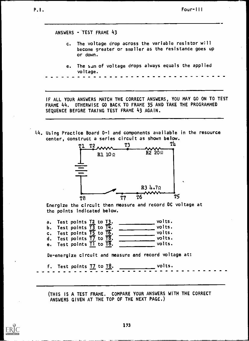
P.I.
ANSWERS -.TEST FRAME 43
c. The voltage drop across the variable resistor willbecome greater or smaller as the resistance goes upor down.
e. The s 'im of voltage drops always equals the applied
voltage.
IMO
IF ALL YOUR ANSWERS MATCH THE CORRECT ANSWERS, YOU MAY GO ON TO TEST
FRAME 44. OTHERWISE GO BACK TO FRAME 35 AND TAKE THE PROGRAMMEDSEQUENCE BEFORE TAKING TEST FRAME 43 AGAIN.
h4. Using Practice Board 0-1 and components available in the resourcecenter, construct a series circuit as shown below.
T1 T2 T3 T4
alninIND
R1 10C/ R2200
R3 11.7st
T8 T7 T6 T5
Energize the circuit then measure and record DC voltage at
the points indicated below.
a. Test points T2 to T3. volts.
b. Test points T3 to W. volts.
c. Test points T5 to Y. volts.
d. Test points T7 to B. volts.
e. Test points T1 to B. volts.
De-energize circuit and measure and record voltage at:
f. Test points T7 to T8. volts.
(THIS IS A TEST FRAME. COMPARE YOUR ANSWERS WITH THE CORRECTANSWERS GIVEN AT THE TOP OF THE NEXT PAGE.)
123
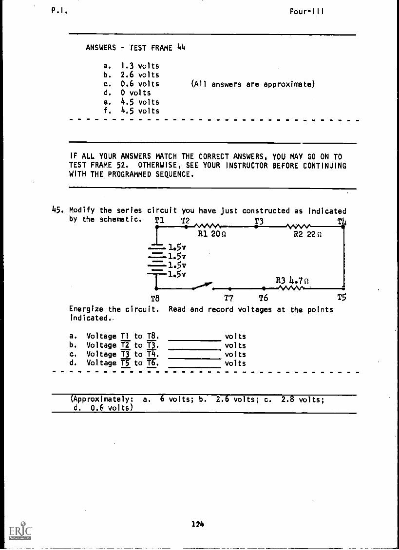
P.I. Four-III
ANSWERS - TEST FRAME 44
a. 1.3 voltsb. 2.6 voltsc. 0.6 voltsd. 0 voltse. 4.5 voltsf. 4.5 volts
(All answers are approximate)
IF ALL YOUR ANSWERS MATCH THE CORRECT ANSWERS, YOU MAY GO ON TOTEST FRAME 52. OTHERWISE, SEE YOUR INSTRUCTOR BEFORE CONTINUINGWITH THE PROGRAMMED SEQUENCE.
45. Modify the series circuit you have just constructed as indicatedby the schematic. T1 T2 T3 T4
Ill 20 Q..ses".ev
R2 22 Q
1.5v=1.5v
1.5v=f-1.5v
R3 4.7s/....."...---, ...../sivsm .
T8 T7 T6 T5
Energize the circuit. Read and record voltages at the pointsindicated,
a. Voltage Ti to T8. voltsb. Voltage T2 to T3. voltsc. Voltage T3 to W. voltsd. Voltage T5 to Tb% volts
(Approximately: a. 6 volts; b. 2.6 volts; c. 2.8 volts;d. 0.6 volts)
124

P.I. Four-III
46. Modify you circuit as indicated by the schematic.
T1 T2 T3
-- 1.5v
1.5v
1.5vR2 10c/ R1 0-50Q
T7 T6 /VYV 15
With variable resistor RI adjusted to 30 ohms (use ohmmeter
to adjust for 30 ohms) measure and record:
Circuit Energized:
111.11.1MM
.=1111
a. applied voltageb. ER1
c. ER2
With variable resistor set at 40 ohms (use ohmmeter to adjust
for 40 ohms) measure and record:
Circuit Energized:
d. source voltagee. ER1
f. ER2
(Approximately: a. 6 volts; b. 4.5 volts; c. 1.5 volts;
d. 6 volts; e. 4.8 volts; f. 1.2 volts)
125

P.I.
47. Again, modify circuit as indicatdd by the schematic.
48. Listed below are the steps for measuring 30-1000 volts DC. We
ENERGIZED
Measure and record the voltage drops between the following points:
a. Ti to T2.
will not actually measure voltages above 30 volts while in the
TOUCHED WHEN THEY ARE CONNECTED TO AN
b. T2 to T3.c. T5 to T7.
Energize Circuit:
2. Plug black test lead into common (-) jack and the red
school because of safety considerations. However, it is important
3. Set the range switch in any of the five voltage-range positions.
5. Turn on the power in the circuit to be tested. If the pointer
4. Connect the black test lead to the negative and the red test
that you understand how to set up the meter to do so. The most
(Approximately: a. 0 volts; b. 1.6 volts; c. 4.4 volts)
important thing to remember is that IF THE VOLTAGE TO BE MEASURED
1. Set the function switch at +DC.
IS OVER 30 VOLTS, NEITHER THE TEST LEADS NOR THE METER SHOULD BE
When in doubt about the voltage, always use the highest voltage
a more accurate reading. (NOTE: De-energize circuit before
deflects to the left of 0, the actual polarity is opposite theanticipated polarity. Turn off the power in the circuit. Set
correct the polarity as applied to the meter.6.
7. Turn off the power in the circuit before nconnecting leads.
test lead into the (+) jack.
Read the voltage on the black arc marked DC.
turning range switch.)
the function switch to -DC and turn the power on. This will
range. Observe the meter reading. If the voltage is within a
lead to the positive side of the cinkuit to be measured.
lower range the switch may be set for the lower range to obtain
==.1.5v
1.5v
TTi
T8
T2
T7
R3 10Q
voltsvolts
voltsRI
22Q
w.ne
126
T6
R2 50c2
T3
CIRCUIT.
T4
5

P.1,;
Four-Ill
49. The Simpson 260-5P multimeter is also capable of measuring
AC voltages. For AC voltages, the function switch must be
placed in the AC position.
What function switch setting is used when measuring alternatingcurrent voltage?
a.
b.
c.
+DCDC AC
+DCDC I
AC
(b)
127

P.I. ILSI COPY AVAILABLE Four-III
50. When measuring AC voltage, the polarity of the meter does nothave to be observed, for the applied voltage changes polarityperiodically. Which drawing shows the multimeter correctlyconnected for measuring AC voltage?
A.
B.
4-
I
(A and B)
128
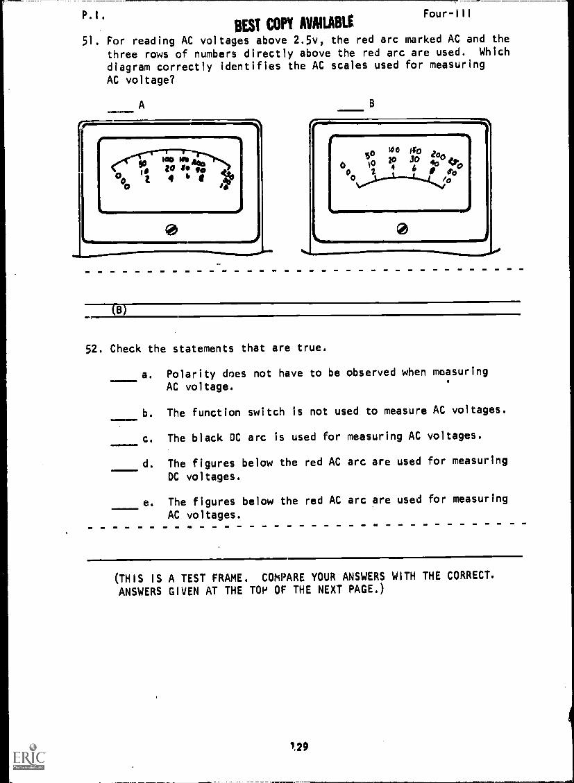
P.I. Four-III
BEST COPY AVAILABLE
51. For reading AC voltages above 2.5v, the red arc marked AC and thethree rows of numbers directly above the red arc are used. Which
diagram correctly identifies the AC scales used for measuring
AC voltage?
A
e oce in10 11144
IDt 6 4
B
0 loo0
2
o 10 JOtoo Ito
46 0 Ob
4o eato
/0
(B)
52. Check the statements that are true.
a. Polarity does not have to be observed when measuring
AC voltage.
b. The function switch is not used to measure AC voltages.
c. The black DC arc is used for measuring AC voltages.
d. The figures below the red AC arc are used for measuring
DC voltages.
e. The figures below the red AC arc are used for measuring
AC voltages.
(THIS IS A TEST FRAME. COMPARE YOUR ANSWERS WITH THE CORRECT.
ANSWERS GIVEN AT THE T01' OF THE NEXT PAGE.)
1,29
P. I . Four-III
ANSWERS - TEST FRAME 52
a. Polarity does not have to be observed when measuringAC voltage.
e. The figures below the red AC arc are used for measuringAC voltages.
IF ALL YOUR ANSWERS MATCH THE CORRECT ANSWERS, YOU MAY GO ON TOTEST FRAME 56. OTHERWISE, GO BACK TO FRAME 45 AND TAKE THE PRO-GRAMMED SEQUENCE BEFORE TAKING TEST FRAME 52 AGAIN.
130

P.I .
53. The meter is
that the red
Range
BEST COPY AVAILABLE
interpreted the same way for AC as for DC except
AC scales are used.
Four-III
switch on 2.5 v
on 1000 v
on 10 v
on 50 v
on 250 v
- read the value directly on thered scale marked 2.5 vac only
- multiply indicated voltage on
the 0-10 AC scale by 100- read voltage on 0-10 AC scale
directly- read voltage on 0-50 AC scale
directly- read voltage on 0-250 AC scale
directly
Interpret the meter AC scale below by matching the indicated
voltage to the range position.
20 is M
810 DI MVO (Ult.pp *Aft all 014M11
civitysoit60
U IIll POVERLOAD PROTECTED
VOLT OHM MILIJAMMETERmon nA/ c SAN! /qv AC
WV 0AN011 ADO 11 01IIAME. A00 10 00
My RANG!' A00 41 00
Range Switch Position Voltage AC
1. 10 v a. 500 volts AC
2. 50 v b. 125 volts AC
3. 2.5 v c. 25 volts AC
4. 250 v d. 1.3 volts AC
5. 1000 v e. 5 volts AC
(I. e; 2. cL 3. d; 4. b; 5. a)
54. Before proceeding with an actual AC voltage measurement, read
the following safety precautions and keep them firmly in mind.
1. DO NOT TOUCH THE METER OR TEST LEADS (EXPOSED METAL) WHILE
POWER IS ON IN THE CIRCUIT BEING MEASURED.
2. BE SURE IS OFF WHEN CONNECTING AND DISCONNECTING
TEST LEM-n-7.--
(POW-ER)
131
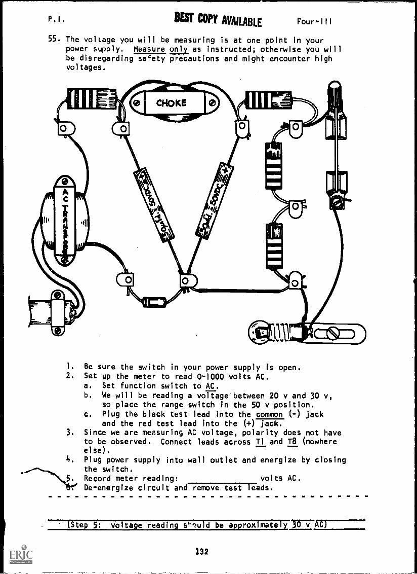
P.1. BEST COPY AVAILABLE Four-III
55. The voltage you will be measuring is at one point in yourpower supply. Measure only as instructed; otherwise you willbe disregarding safety precautions and might encounter highvoltages.
1. Be sure the switch in your power supply is open.2. Set up the meter to read 0-1000 volts AC.
a. Set function switch to AC.b. We will be reading a voltage between 20 v and 30 v,
so place the range switch in the 50 v position.c. Plug the black test lead into the common (-) jack
and the red test lead into the (+) jack.3. Since we are measuring AC voltage, polarity does not have
to be observed. Connect leads across Ti and T8 (nowhereelse).
4. Plug power supply into wall outlet and energize by closingthe switch.
5. Record meter reading: volts AC.. De-energize circuit and remove test leads.
(Step voltage reading s', -7,uld be approximately TrsTAC)
132

P. I . BEST COPY AVAILABLE Four-III
56. Interpret the meter reading and record the indicated AC
voltage for each range switch position.
15 10
509 rr
1K2K
6
a .4,
t 4,4%)et4.to
MO 06 066111
ID 6rAlf6
6011 OHMS
1. 10 v
2. 50 v
3. 2.5 v
4. 250 v
5. 1000 v
ctimNultiX
260OR /110 se
OVERLOAD PR ECTED
VOLT OHM MEMmoo AAV .040 API AC.
volts AC
volts AC
volts AC
volts AC
volts AC
V SANG'S ADO q De06 V lomat ADD 16 06
DOD NAND's ADD On
(THIS IS A TEST FRAME. COMPARE YOUR ANSWERS WITH THE CORRECT
ANSWERS GIVEN ON THE TOP OF THE NEXT PAGE.)
133
P.I. Four-III
ANSWERS - TEST FRAME 56
1. 7.2 VAC
2. 36 VAC
3. 1.8 VAC
4. 180 VAC
5. 720 VAC
IF YOUR ANSWERS ARE INCORRECT, GO BACK TO FRAME 53 AND TAKE THEPROGRAMMED SEQUENCE.
IF YOUR ANSWERS ARE CORRECT, YOU MAY TAKE THE PROGRESS CHECK, ORYOU MAY STUDY ANY OF THE OTHER RESOURCES LISTED. IF YOU TAKE THEPROGRESS CHECK AND ANSWER ALL THE QUESTIONS CORRECTLY, YOU HAVE.MASTERED THE MATERIAL AND ARE READY TO TAKE THE MODULE TEST. SEEYOUR INSTRUCTOR.
IF YOU DFCIDE NOT TO TAKE THE PROGRESS CHECK AT THIS TIME, OR IFYOU MISSED ONE OR MORE QUESTIONS STUDY ANY METHOD OF INSTRUCTIONYOU WISH UNTIL YOU HAVE ANSWERED ALL THE PROGRESS CHECK QUESTIONSCORRECTLY. THEN SEE YOUR INSTRUCTOR AND ASK TO TAKE THE MODULETEST.
134

Summary Four-III
SUMMARY
LESSON III
Using the Multimeter as a Voltmeter
You have learned to use the multimeter as an ohmmeter and as anammeter; now let's discuss its use as a voltmeter.
Basically, all meters utilize current flow in making a measurement,
for work is done in a circuit only when current flows. In other words,
it is the current flow through the meter which causes the pointerto move. A voltmeter scale is calibrated so that it indicates theamount of voltage which causes current to flow through a multiplier
resistor. The internal multiplier resistor determines the maximumvoltage the meter can read and limits the meter current to a safe
value. The range switch selects different meter ranges by selectingdifferent multiplier resistors.
On the Simpson 260-5P, all DC voltages are read on the second scale
from the top. Which of the three rows of numbers you read will de-
pend on the range-switch setting. Some scales will require you to
move the decimal point mentally to get the correct value.
The DC voltage ranges are 0 to 2.5 v, 0 to 10 v, 0 to 50 v, 0 to 250 v,
and 0 to 1000 v. There is also a 0 to 5000 v scale which uses the 0
to 1000 v range switch setting with a special jack for the positive
lead. The meter has corresponding AC voltage ranges which use thesame numbers but are read on the red scale below the numbers. A
separate 5000 v AC jack for the positive lead and a special scale for
reading the 2.5 v AC range are the only differences from the DC
functions.
To read voltages, you will use a method similar to the one used with
the simple voltmeter. Make sure that the function switch (AC, -DC,
+DC) is in the proper position and that the range switch is set at a
larger value than the voltage you expect to measure before you touch
your probes to the circuit. If you are not certain of the voltage, start
with the highest scale (1000V) and reduce the range setting to get an
easily read meter deflection. Do not reduce the range setting to a
position that is below the voltage being measured.
The voltages you will be measuring here are all less than 30 volts,
but later (in other schools or in the fleet) you will measure
voltage in excess of 30 volts.
HIGH VOLTAGE MEASUREMENTS REQUIRE SPECIAL CARE TO PROTECT YOU FROM
INJURY OR DEATH.
The special rule for measuring voltages in excess of 30 volts is:
Always clrenergize the circuit before touching the meter, meter
leads, or any part of the circuit.
135

Summary
The procedures to follow for making these readings are:
1. Turn off the circuit.2. Connect the meter clip leads to the points where voltage
is to be measured.3. Set the meter function and scale as required. Check
that connections are correct.4. Keeping well away from the meter, leads, and circuit,
energize the circuit and make the reading. If it is
necessary to change any meter settings, turn off the cir-cuit before you touch the meter.
5. Turn off the circuit and disconnect the meter.
If you are sure you understand how to use the multimeter safelyas a voltmeter and you intend to take the progress check immed-iately following this summary, perform the experiments containedin the Narrative (pages 10-14). Keep both your safety, and themeter's safety in mind.
If you do not understand, first study either the narrative orthe programmed instruction, or see your instructor.
AT THIS POINT, YOU MAY TAKE THE LESSON PROGRESS CHECK, OR YOUMAY STUDY THE LESSON NARRATIVE OR THE PROGRAMMED INSTRUCTION ORBOTH. IF YOU TAKE THE PROGRESS CHECK AND ANSWER ALL OF THE QUES-TIONS CORRECTLY, YOU HAVE MASTERED THE MATERIAL AND ARE READY TOTAKE THE MODULE TEST. SEE YOUR INSTRUCTOR.
IF YOU DECIDE NOT TO TAKE THE PROGRESS CHECK AT THIS TIME, ORIF YOU MISSED ONE OR MORE QUESTIONS, STUDY ANY METHOD OF IN-STRUCTION YOU WISH UNTIL YOU HAVE ANSWERED ALL THE PROGRESSCHECK QUESTIONS CORRECTLY. THEN SEE YOUR INSTRUCTOR AND ASKTO TAKE THE MODULE TEST.
136