measuring - ecollegelocal.ecollege.ie/content/apprentice/liu/ind_insulation/mod3/m3_u1.pdf · 2.0...
TRANSCRIPT
TRADE OF
Industrial Insulation
PHASE 2
Module 3
Substructures, Advanced Cold Work and Cladding
UNIT: 1
Measuring

Produced by
In cooperation with subject matter expert:
Michael Kelly
© SOLAS 2014
Module 3– Unit 1
Industrial Insulation Phase 2
Measuring
Revision 2.0, August 2014
Table of Contents Unit Objective .............................................................................................................. 1
Introduction .................................................................................................................. 2
1.0 Pipe-Work and Fittings ............................................................................ 3
1.1 Information on Pipe-Work ....................................................................... 3 1.2 Measuring of Basic Pipe Work Fittings ................................................... 3 1.3 Measuring a “Gate” Valve ......................................................................... 4 1.4 Standard Pipe-Work Symbols ................................................................... 5
2.0 Measuring and Sketching ......................................................................... 7
2.1 Measurement of Circumference Using a 5m Tape ................................ 7 2.2 Circumference and Area Calculation ....................................................... 8 2.3 Callipers ....................................................................................................... 9 2.4 Sketching ...................................................................................................... 9 2.5 Recording Measurements ........................................................................10
3.0 Material Requirements ............................................................................ 12
3.1 Calculating Allowances for Insulation ...................................................12 3.2 Obstacle Location on Pipe-Work ...........................................................14 3.3 Positioning of Joints .................................................................................15
Summary ...................................................................................................................... 16
Module 3– Unit 1
Industrial Insulation Phase 2
1
Measuring
Revision 2.0, August 2014
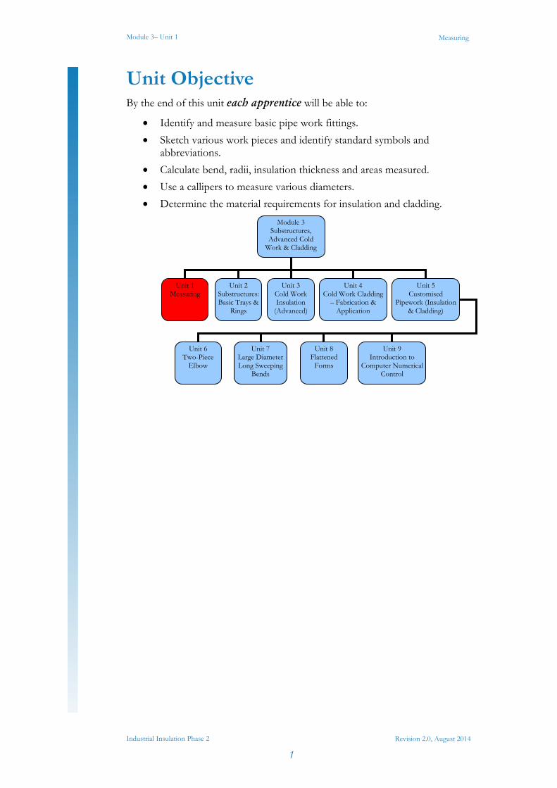
Unit Objective By the end of this unit each apprentice will be able to:
Identify and measure basic pipe work fittings.
Sketch various work pieces and identify standard symbols and abbreviations.
Calculate bend, radii, insulation thickness and areas measured.
Use a callipers to measure various diameters.
Determine the material requirements for insulation and cladding.
Module 3 Substructures,
Advanced Cold Work & Cladding
Unit 1 Measuring
Unit 2 Substructures: Basic Trays &
Rings
Unit 3 Cold Work Insulation
(Advanced)
Unit 5 Customised
Pipework (Insulation & Cladding)
Unit 4 Cold Work Cladding
– Fabrication & Application
Unit 6 Two-Piece
Elbow
Unit 7 Large Diameter Long Sweeping
Bends
Unit 8 Flattened
Forms
Unit 9 Introduction to
Computer Numerical Control
Module 3– Unit 1
Industrial Insulation Phase 2
2
Measuring
Revision 2.0, August 2014
Introduction A pipeline or pipe-work system is usually made up of various diameter pipes and fittings. These fittings would include 90 and 45 degree radius bends, reducers (concentric and eccentric), tees (equal and unequal), hangers and supports, and various types of valves to regulate and control flow. Pipes and fittings can be welded together or flanged and bolted. Other methods of fixing and connection pipes and fittings are also available.
Module 3– Unit 1
Industrial Insulation Phase 2
3
Measuring
Revision 2.0, August 2014
1.0 Pipe-Work and Fittings
1.1 Information on Pipe-Work Pipe is specified by stating its nominal size and it should be noted particularly that the nominal size is only approximate, and is neither the inside or the outside diameter and standard tables or manufacturers’ tables should be used to ascertain exactly these two dimensions. Pipes over 14 inches (356mm) are generally specified on the outside diameter and wall thickness. To explain how this works, if you purchase a 2" pipe (this is the nominal; size), this pipe will have an outside diameter of 2.375 inches ( 60.325mm). For pipes up to 12 inch diameter, the nominal diameter is very loosely related to the inside diameter. As mentioned above pipes of 14 inches (356mm) and over are generally specified on outside diameter and wall thickness. It is important to mention that the wall thickness of pipes of the same diameter can be different, but the outside diameters will always be the same. This is to facilitate the connection of various parts of pipe-line systems such as bends, tees, valves etc.
It is worth mentioning that sometimes pipes are referred to as tubes and the reverse also applies. Tubes, particularly those in copper and brass and in some cases steel, nickel, and other metals and non-metals, are manufactured and marketed on the basis of actual outside diameter and wall thickness and, as they are drawn in a variety of thicknesses, both must be specified.
1.2 Measuring of Basic Pipe Work Fittings
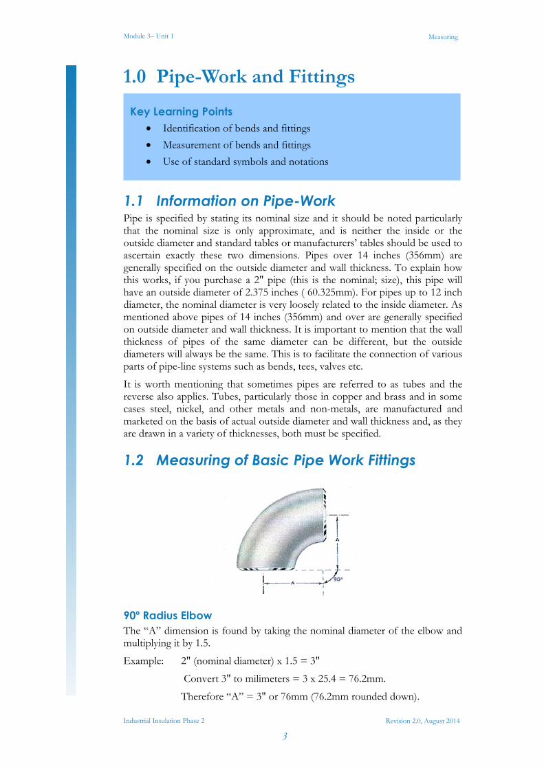
90º Radius Elbow The “A” dimension is found by taking the nominal diameter of the elbow and multiplying it by 1.5.
Example: 2" (nominal diameter) x 1.5 = 3"
Convert 3" to milimeters = 3 x 25.4 = 76.2mm.
Therefore “A” = 3" or 76mm (76.2mm rounded down).
Key Learning Points Identification of bends and fittings
Measurement of bends and fittings
Use of standard symbols and notations
Module 3– Unit 1
Industrial Insulation Phase 2
4
Measuring
Revision 2.0, August 2014
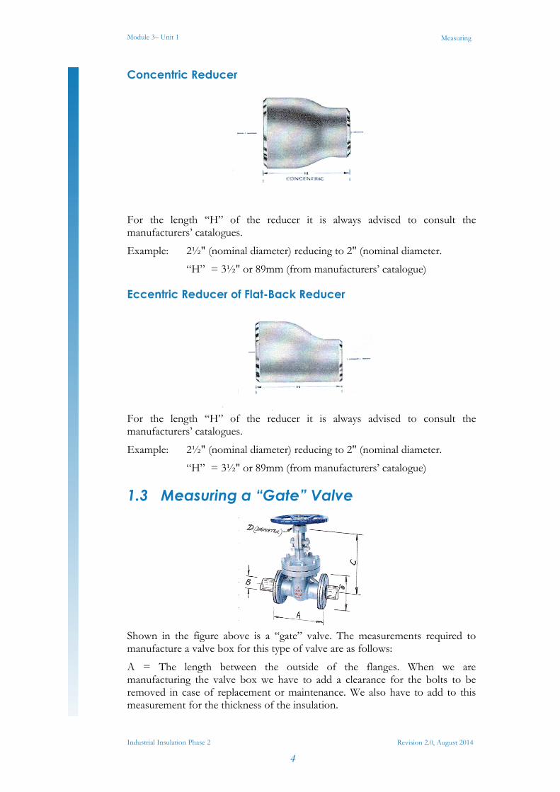
Concentric Reducer
For the length “H” of the reducer it is always advised to consult the manufacturers’ catalogues.
Example: 2½" (nominal diameter) reducing to 2" (nominal diameter.
“H” = 3½" or 89mm (from manufacturers’ catalogue)
Eccentric Reducer of Flat-Back Reducer
For the length “H” of the reducer it is always advised to consult the manufacturers’ catalogues.
Example: 2½" (nominal diameter) reducing to 2" (nominal diameter.
“H” = 3½" or 89mm (from manufacturers’ catalogue)
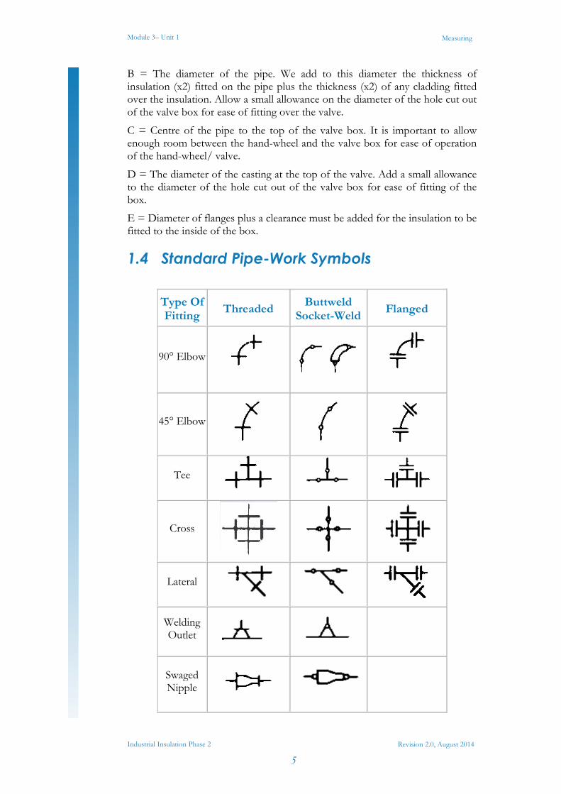
1.3 Measuring a “Gate” Valve
Shown in the figure above is a “gate” valve. The measurements required to manufacture a valve box for this type of valve are as follows:
A = The length between the outside of the flanges. When we are manufacturing the valve box we have to add a clearance for the bolts to be removed in case of replacement or maintenance. We also have to add to this measurement for the thickness of the insulation.
Module 3– Unit 1
Industrial Insulation Phase 2
5
Measuring
Revision 2.0, August 2014
B = The diameter of the pipe. We add to this diameter the thickness of insulation (x2) fitted on the pipe plus the thickness (x2) of any cladding fitted over the insulation. Allow a small allowance on the diameter of the hole cut out of the valve box for ease of fitting over the valve.
C = Centre of the pipe to the top of the valve box. It is important to allow enough room between the hand-wheel and the valve box for ease of operation of the hand-wheel/ valve.
D = The diameter of the casting at the top of the valve. Add a small allowance to the diameter of the hole cut out of the valve box for ease of fitting of the box.
E = Diameter of flanges plus a clearance must be added for the insulation to be fitted to the inside of the box.
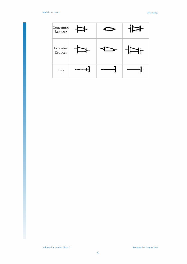
1.4 Standard Pipe-Work Symbols
Type Of Fitting
Threaded Buttweld
Socket-WeldFlanged
90° Elbow
45° Elbow
Tee
Cross
Lateral
Welding Outlet
Swaged Nipple
Module 3– Unit 1
Industrial Insulation Phase 2
6
Measuring
Revision 2.0, August 2014
ConcentricReducer
Eccentric Reducer
Cap
Module 3– Unit 1
Industrial Insulation Phase 2
7
Measuring
Revision 2.0, August 2014
2.0 Measuring and Sketching
2.1 Measurement of Circumference Using a 5m Tape
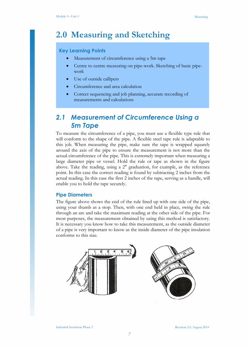
To measure the circumference of a pipe, you must use a flexible type rule that will conform to the shape of the pipe. A flexible steel tape rule is adaptable to this job. When measuring the pipe, make sure the tape is wrapped squarely around the axis of the pipe to ensure the measurement is not more than the actual circumference of the pipe. This is extremely important when measuring a large diameter pipe or vessel. Hold the rule or tape as shown in the figure above. Take the reading, using a 2" graduation, for example, as the reference point. In this case the correct reading is found by subtracting 2 inches from the actual reading. In this case the first 2 inches of the tape, serving as a handle, will enable you to hold the tape securely.
Pipe Diameters The figure above shows the end of the rule lined up with one side of the pipe, using your thumb as a stop. Then, with one end held in place, swing the rule through an arc and take the maximum reading at the other side of the pipe. For most purposes, the measurement obtained by using this method is satisfactory. It is necessary you know how to take this measurement, as the outside diameter of a pipe is very important to know as the inside diameter of the pipe insulation conforms to this size.
Key Learning Points Measurement of circumference using a 5m tape
Centre to centre measuring on pipe-work. Sketching of basic pipe-work
Use of outside callipers
Circumference and area calculation
Correct sequencing and job planning, accurate recording of measurements and calculations
Module 3– Unit 1
Industrial Insulation Phase 2
8
Measuring
Revision 2.0, August 2014
2.2 Circumference and Area Calculation As a tradesman it is important to be able to work out the surface area of different components, that is to calculate the amount of material that is required to manufacture those components. Whether you are manufacturing a ventilation ductwork system or cladding a steam pipe section you need to be able to work out the amount of material you will need to do the job.
When calculating the area of a cylinder or pipe the measurements we are concerned with are the circumference of the pipe and the height or length of the pipe. It is important for the apprentice to understand the need for accuracy when calculating the circumference of a pipe or cylinder as inaccuracies can lead to poor and sloppy fit-up of parts and poor overall quality of the job.
Example 1 Calculate the surface area of a circular duct ø200mm x 600mm long.
So: Circumference of the pipe = πd
= 3.14 x 20cm
= 62.8cm
Surface area of the pipe= Circumference x height/ length
= 62.8 cm x 60cm
= 3768cm²
Example 2 Calculate the surface area of a circular duct ø15 cm x 45 cm long,
So: Circumference of the pipe = πd
= 3.14 x 15cm
= 47.1cm
Surface area of the pipe= Circumference x height/ length
= 47.1cm x 45cm
= 2119.5cm²
Module 3– Unit 1
Industrial Insulation Phase 2
9
Measuring
Revision 2.0, August 2014
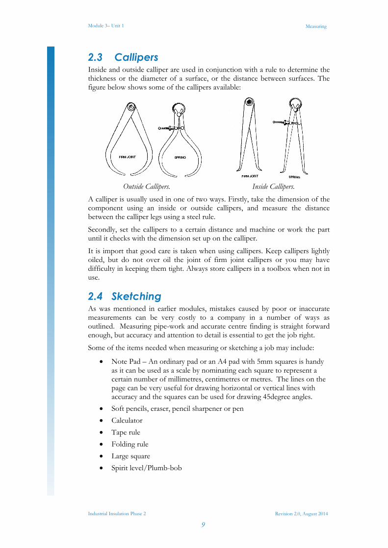
2.3 Callipers Inside and outside calliper are used in conjunction with a rule to determine the thickness or the diameter of a surface, or the distance between surfaces. The figure below shows some of the callipers available:
Outside Callipers. Inside Callipers.
A calliper is usually used in one of two ways. Firstly, take the dimension of the component using an inside or outside callipers, and measure the distance between the calliper legs using a steel rule.
Secondly, set the callipers to a certain distance and machine or work the part until it checks with the dimension set up on the calliper.
It is import that good care is taken when using callipers. Keep callipers lightly oiled, but do not over oil the joint of firm joint callipers or you may have difficulty in keeping them tight. Always store callipers in a toolbox when not in use.
2.4 Sketching As was mentioned in earlier modules, mistakes caused by poor or inaccurate measurements can be very costly to a company in a number of ways as outlined. Measuring pipe-work and accurate centre finding is straight forward enough, but accuracy and attention to detail is essential to get the job right.
Some of the items needed when measuring or sketching a job may include:
Note Pad – An ordinary pad or an A4 pad with 5mm squares is handy as it can be used as a scale by nominating each square to represent a certain number of millimetres, centimetres or metres. The lines on the page can be very useful for drawing horizontal or vertical lines with accuracy and the squares can be used for drawing 45degree angles.
Soft pencils, eraser, pencil sharpener or pen
Calculator
Tape rule
Folding rule
Large square
Spirit level/Plumb-bob
Module 3– Unit 1
Industrial Insulation Phase 2
10
Measuring
Revision 2.0, August 2014
When taking measurements of a job we may use the surrounding building structure – floor, walls, ceiling, steelwork etc. – to help us get the measurements we require. A lot of the time this won’t be necessary because we can take our measurements directly from the job e.g. duct system, pipe-work, tank/vessel etc. Sometimes a combination of both of these methods will be used depending on the system design and location. Some important things to take into account when sketching a job would be as follows:
Study the object you are going to sketch.
Form a mental picture of the overall object noting prominent features.
Decide on which views you want to sketch the job in e.g. Plan view, elevation etc
Begin to read less complicated features, study the job from different angles taking note of possible obstacles that may alter the final installation.
Read the more complicated features, use imaginary projection lines to locate surfaces and edges, and understand how they relate to the different views you want to sketch.
Study any detail features that are still unclear.
Include written notes to the sketch to clarify different aspects of the job which may still remain unclear.
2.5 Recording Measurements When sketching a job it is vitally important that the measurements you record on the sketch are clear, concise and accurate. The measurements that you record are a form of communication for the person fabricating the parts, as they will not have seen the job and are depending on your sketch for the correct information. Some important factors to take into consideration when recording measurements onto a sketch are:
1. Measurements should be shown clearly on the sketch. 2. The section of the job that is measured should be indicated on the sketch
using arrows showing the start point of the measurement to the finishing point of the measurement.
3. When using the metric system to record measurements decide before measuring the job whether to use millimetres, centimetres or meters.
4. Make a note on the sketch to indicate whether your measurements include allowances for joints, hems etc or if they have to be allowed for during the fabrication process.
5. When measuring pipe work use an outside callipers to accurately measure the outside diameter of the pipe.
6. If the finished job requires insulation and cladding ensure that there is sufficient space around the pipe work for the materials. Sometimes cladding may have to be manufactured in two halves so as to allow for installation.
7. Ensure that your measurements are accurate as this will speed up the fabrication time and reduce costs.
Module 3– Unit 1
Industrial Insulation Phase 2
11
Measuring
Revision 2.0, August 2014
8. Spend time double checking your measurements and make sure you have not forgotten a measurement.
9. The apprentice should always be working to a tolerance no more than ± 2mm as anything outside of this will not allow for a clean and accurate fit up of parts.
Module 3– Unit 1
Industrial Insulation Phase 2
12
Measuring
Revision 2.0, August 2014
3.0 Material Requirements
3.1 Calculating Allowances for Insulation Area of a Square The area of a Square = Length of Side x Length of Side.
Example Duct Size = 600mm x 600mm or 0.6m x 0.6m.
Area of Duct = 360,000mm² or 0.36m².
Area of a Rectangle Area of a Rectangle = Length x Width.
Example Duct Size = 800mm x 400mm or 0.8m x 0.4m.
= 320,000mm² or 0.32m².
Area of a Circle The area of a circle= πr².
Example Spiral duct size = 500mm diameter or 0.5m
Area = πr²
Area = 3.14 x 250²mm or 3.14 x .25m²
Area = 196,250mm² or 0.19625m²
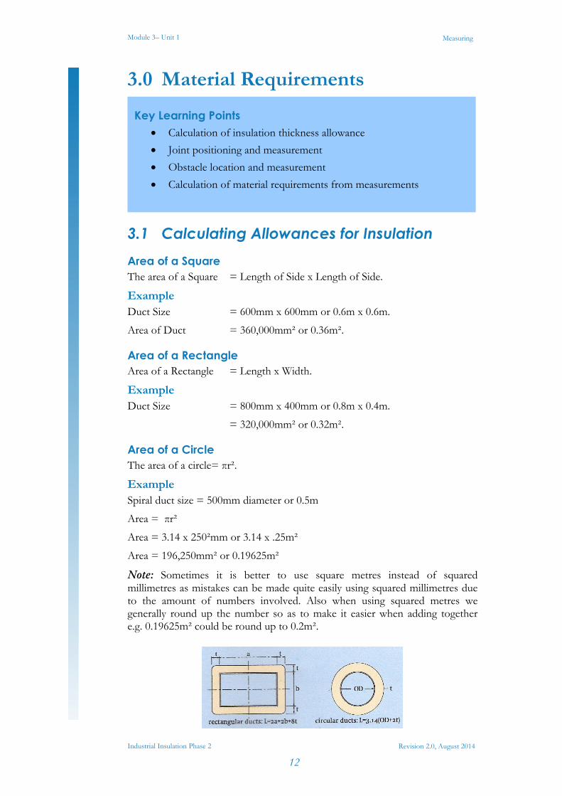
Note: Sometimes it is better to use square metres instead of squared millimetres as mistakes can be made quite easily using squared millimetres due to the amount of numbers involved. Also when using squared metres we generally round up the number so as to make it easier when adding together e.g. 0.19625m² could be round up to 0.2m².
Key Learning Points Calculation of insulation thickness allowance
Joint positioning and measurement
Obstacle location and measurement
Calculation of material requirements from measurements
Module 3– Unit 1
Industrial Insulation Phase 2
13
Measuring
Revision 2.0, August 2014
Insulation Allowance for a Square/Rectangular Duct The amount of insulation required for the perimeter of a square or rectangular duct is: L = 2A + 2B + 8T
Example Calculate the total length of insulation required to cover a 400mm x 300mm duct with 25mm fibreglass ductwrap.
Solution Length of side A = 400mm
Length of side B = 300mm
Insulation thickness = 25mm.
So: L = 2A + 2B + 8T
L = 2(400mm) + 2(300mm) + 8(25mm)
L = 800mm+600mm+200mm
L = 1600mm
Note: To find the area of material required we must multiply the perimeter of insulation by the height of the duct.
Insulation Allowance for a Circular Duct The amount of insulation required for the perimeter of a circular duct is: L = 3.14(OD + 2T).
Example Calculate the total length of insulation required to cover a 200mm diameter circular duct with 25mm fibreglass ductwrap.
Solution L = 3.14(OD + 2T).
L = 3.14(200mm + 2(25mm)).
L = 3.14(200mm + 50mm).
L = 3.14 (250mm)
L = 785mm
Note: To find the area of material required we must multiply the perimeter of insulation by the height of the duct.
Module 3– Unit 1
Industrial Insulation Phase 2
14
Measuring
Revision 2.0, August 2014
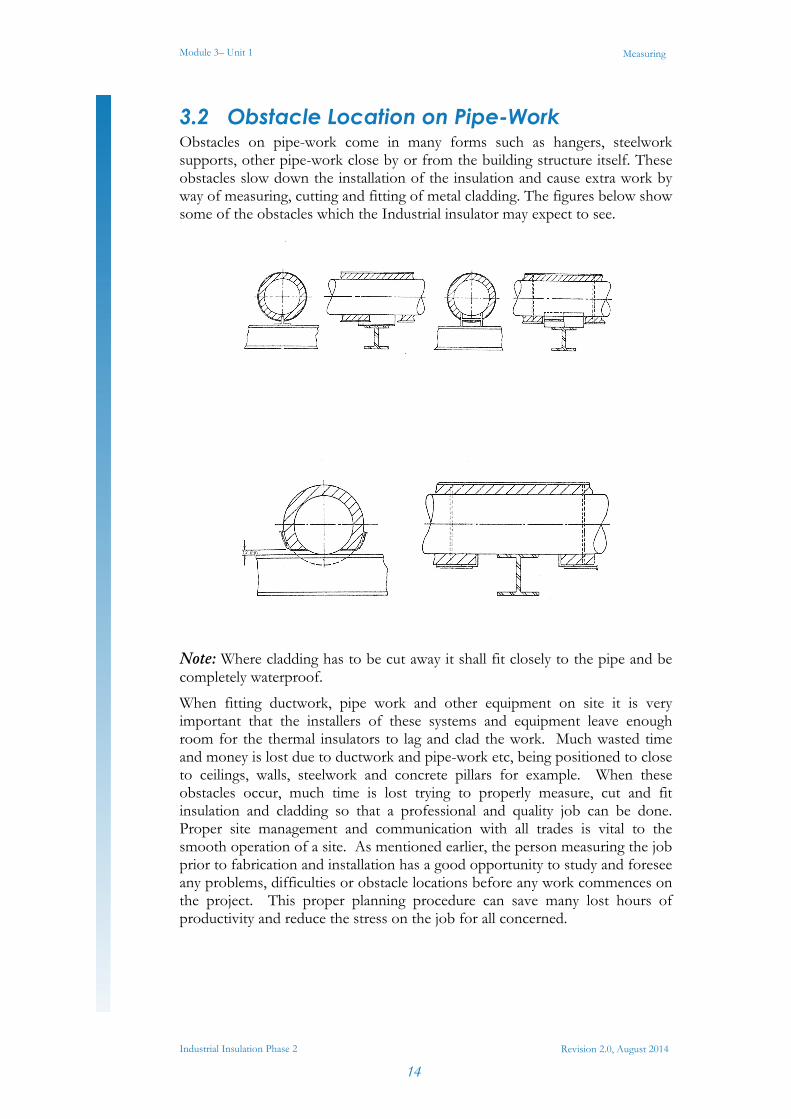
3.2 Obstacle Location on Pipe-Work Obstacles on pipe-work come in many forms such as hangers, steelwork supports, other pipe-work close by or from the building structure itself. These obstacles slow down the installation of the insulation and cause extra work by way of measuring, cutting and fitting of metal cladding. The figures below show some of the obstacles which the Industrial insulator may expect to see.
Note: Where cladding has to be cut away it shall fit closely to the pipe and be completely waterproof.
When fitting ductwork, pipe work and other equipment on site it is very important that the installers of these systems and equipment leave enough room for the thermal insulators to lag and clad the work. Much wasted time and money is lost due to ductwork and pipe-work etc, being positioned to close to ceilings, walls, steelwork and concrete pillars for example. When these obstacles occur, much time is lost trying to properly measure, cut and fit insulation and cladding so that a professional and quality job can be done. Proper site management and communication with all trades is vital to the smooth operation of a site. As mentioned earlier, the person measuring the job prior to fabrication and installation has a good opportunity to study and foresee any problems, difficulties or obstacle locations before any work commences on the project. This proper planning procedure can save many lost hours of productivity and reduce the stress on the job for all concerned.
Module 3– Unit 1
Industrial Insulation Phase 2
15
Measuring
Revision 2.0, August 2014
3.3 Positioning of Joints Joints should be arranged when fitted to shed water, as water is the number one enemy of an insulation system. If water gets into a joint it can wet the insulation but over time it can cause major problems by way of corrosion to pipe-work etc under the insulation. This can be a very costly problem if it is not rectified in time.The positioning of the joint is decided by a number of factors:
1. Shedding of water in cladding work. 2. Appearance and the overall look of the job. 3. Strength of a piece. 4. Nesting of materials to minimise waste. There are many joints in sheet metal. Some joints are called self-secured joints, where we allow extra material on the pattern to form the joint. Examples are Groove joint, Slip joint, Paned joint and the lap joint. Each joint will require a different amount of metal to be added on for their assembly.
Module 3– Unit 1
Industrial Insulation Phase 2
16
Measuring
Revision 2.0, August 2014
Summary Insulation and cladding is applied to pipe-work and tubes to control heat loss or gain, for protection against frost and other environmental elements and to protect personnel from injury.
A pipeline or pipe-work system is usually made up of various diameter pipes and fittings. Various tools are used to measure both the inside and outside diameters of pipe and tube. These tools include a steel rule, a tape rule, an inside and outside callipers. Care should be taken when using these tools and regular maintenance such as the oiling of joints is important to ensure continuous operation of the tools.
Planning and organisation is vitally important when measuring a large insulation and cladding job. Communication between people and the delegation of tasks will ensure the smooth running of the job. Record keeping, filing of drawings, notes and understanding the works specification are all very important aspects of any job, and a system should be in place whereby information is available in a clear and concise and organised manner.

Castleforbes House Castleforbes Road
Dublin 1