mec226 ch3
TRANSCRIPT

MECHANICS OF
MATERIALS
Third Edition
Ferdinand P. Beer
E. Russell Johnston, Jr.
John T. DeWolf
Lecture Notes:
J. Walt Oler
Texas Tech University
CHAPTER
© 2002 The McGraw-Hill Companies, Inc. All rights reserved.
3 Torsion

© 2002 The McGraw-Hill Companies, Inc. All rights reserved.
MECHANICS OF MATERIALS
Th
ird
Ed
ition
Beer • Johnston • DeWolf
3 - 2
Contents
Introduction
Torsional Loads on Circular Shafts
Net Torque Due to Internal Stresses
Axial Shear Components
Shaft Deformations
Shearing Strain
Stresses in Elastic Range
Normal Stresses
Torsional Failure Modes
Angle of Twist in Elastic Range
Design of Transmission Shafts
Stress Concentrations

© 2002 The McGraw-Hill Companies, Inc. All rights reserved.
MECHANICS OF MATERIALS
Th
ird
Ed
ition
Beer • Johnston • DeWolf
3 - 3
Torsional Loads on Circular Shafts
• Interested in stresses and strains of
circular shafts subjected to twisting
couples or torques
• Generator creates an equal and
opposite torque T’
• Shaft transmits the torque to the
generator
• Turbine exerts torque T on the shaft
© 2002 The McGraw-Hill Companies, Inc. All rights reserved.
MECHANICS OF MATERIALS
Th
ird
Ed
ition
Beer • Johnston • DeWolf
3 - 4
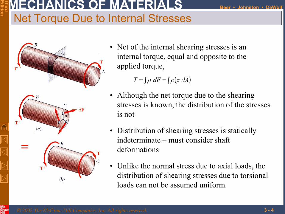
Net Torque Due to Internal Stresses
dAdFT
• Net of the internal shearing stresses is an
internal torque, equal and opposite to the
applied torque,
• Although the net torque due to the shearing
stresses is known, the distribution of the stresses
is not
• Unlike the normal stress due to axial loads, the
distribution of shearing stresses due to torsional
loads can not be assumed uniform.
• Distribution of shearing stresses is statically
indeterminate – must consider shaft
deformations

© 2002 The McGraw-Hill Companies, Inc. All rights reserved.
MECHANICS OF MATERIALS
Th
ird
Ed
ition
Beer • Johnston • DeWolf
3 - 5
Axial Shear Components
• Torque applied to shaft produces shearing
stresses on the faces perpendicular to the
axis.
• The existence of the axial shear components is
demonstrated by considering a shaft made up
of axial slats.
The slats slide with respect to each other when
equal and opposite torques are applied to the
ends of the shaft.
• Conditions of equilibrium require the
existence of equal stresses on the faces of the
two planes containing the axis of the shaft

© 2002 The McGraw-Hill Companies, Inc. All rights reserved.
MECHANICS OF MATERIALS
Th
ird
Ed
ition
Beer • Johnston • DeWolf
3 - 6
• From observation, the angle of twist of the
shaft is proportional to the applied torque and
to the shaft length.
L
T
Shaft Deformations
• When subjected to torsion, every cross-section
of a circular shaft remains plane and
undistorted.
• Cross-sections of noncircular (non-
axisymmetric) shafts are distorted when
subjected to torsion.
• Cross-sections for hollow and solid circular
shafts remain plain and undistorted because a
circular shaft is axisymmetric.

© 2002 The McGraw-Hill Companies, Inc. All rights reserved.
MECHANICS OF MATERIALS
Th
ird
Ed
ition
Beer • Johnston • DeWolf
3 - 7
Shearing Strain
• Consider an interior section of the shaft. As a
torsional load is applied, an element on the
interior cylinder deforms into a rhombus.
• Shear strain is proportional to twist and radius
maxmax and
cL
c
LL
or
• It follows that
• Since the ends of the element remain planar,
the shear strain is equal to angle of twist.

© 2002 The McGraw-Hill Companies, Inc. All rights reserved.
MECHANICS OF MATERIALS
Th
ird
Ed
ition
Beer • Johnston • DeWolf
3 - 8
Stresses in Elastic Range
Jc
dAc
dAT max2max
• Recall that the sum of the moments from
the internal stress distribution is equal to
the torque on the shaft at the section,
4
21 cJ
41
422
1 ccJ
and maxJ
T
J
Tc
• The results are known as the elastic torsion
formulas,
• Multiplying the previous equation by the
shear modulus,
max
Gc
G
max
c
From Hooke’s Law, G , so
The shearing stress varies linearly with the
radial position in the section.

© 2002 The McGraw-Hill Companies, Inc. All rights reserved.
MECHANICS OF MATERIALS
Th
ird
Ed
ition
Beer • Johnston • DeWolf
3 - 9
Normal Stresses
• Elements with faces parallel and perpendicular
to the shaft axis are subjected to shear stresses
only. Normal stresses, shearing stresses or a
combination of both may be found for other
orientations.
max0
0max45
0max0max
2
2
245cos2
o
A
A
A
F
AAF
• Consider an element at 45o to the shaft axis,
• Element a is in pure shear.
• Note that all stresses for elements a and c have
the same magnitude
• Element c is subjected to a tensile stress on
two faces and compressive stress on the other
two.

© 2002 The McGraw-Hill Companies, Inc. All rights reserved.
MECHANICS OF MATERIALS
Th
ird
Ed
ition
Beer • Johnston • DeWolf
3 - 10
Torsional Failure Modes
• Ductile materials generally fail in
shear. Brittle materials are weaker in
tension than shear.
• When subjected to torsion, a ductile
specimen breaks along a plane of
maximum shear, i.e., a plane
perpendicular to the shaft axis.
• When subjected to torsion, a brittle
specimen breaks along planes
perpendicular to the direction in
which tension is a maximum, i.e.,
along surfaces at 45o to the shaft
axis.

© 2002 The McGraw-Hill Companies, Inc. All rights reserved.
MECHANICS OF MATERIALS
Th
ird
Ed
ition
Beer • Johnston • DeWolf
3 - 11
Shaft BC is hollow with inner and outer
diameters of 90 mm and 120 mm,
respectively. Shafts AB and CD are solid
of diameter d. For the loading shown,
determine (a) the minimum and maximum
shearing stress in shaft BC, (b) the
required diameter d of shafts AB and CD
if the allowable shearing stress in these
shafts is 65 MPa.
Sample Problem 3.1
SOLUTION:
• Cut sections through shafts AB
and BC and perform static
equilibrium analysis to find
torque loadings
• Given allowable shearing stress
and applied torque, invert the
elastic torsion formula to find the
required diameter
• Apply elastic torsion formulas to
find minimum and maximum
stress on shaft BC

© 2002 The McGraw-Hill Companies, Inc. All rights reserved.
MECHANICS OF MATERIALS
Th
ird
Ed
ition
Beer • Johnston • DeWolf
3 - 12
SOLUTION:
• Cut sections through shafts AB and BC
and perform static equilibrium analysis
to find torque loadings
CDAB
ABx
TT
TM
mkN6
mkN60
mkN20
mkN14mkN60
BC
BCx
T
TM
Sample Problem 3.1

© 2002 The McGraw-Hill Companies, Inc. All rights reserved.
MECHANICS OF MATERIALS
Th
ird
Ed
ition
Beer • Johnston • DeWolf
3 - 13
• Apply elastic torsion formulas to
find minimum and maximum
stress on shaft BC
46
4441
42
m1092.13
045.0060.022
ccJ
MPa2.86
m1092.13
m060.0mkN2046
22max
J
cTBC
MPa7.64
mm60
mm45
MPa2.86
min
min
2
1
max
min
c
c
MPa7.64
MPa2.86
min
max
• Given allowable shearing stress and
applied torque, invert the elastic torsion
formula to find the required diameter
m109.38
mkN665
3
3
2
4
2
max
c
cMPa
c
Tc
J
Tc
mm8.772 cd
Sample Problem 3.1

© 2002 The McGraw-Hill Companies, Inc. All rights reserved.
MECHANICS OF MATERIALS
Th
ird
Ed
ition
Beer • Johnston • DeWolf
3 - 14
Angle of Twist in Elastic Range
• Recall that the angle of twist and maximum
shearing strain are related,
L
c max
• In the elastic range, the shearing strain and shear
are related by Hooke’s Law,
JG
Tc
G max
max
• Equating the expressions for shearing strain and
solving for the angle of twist,
JG
TL
• If the torsional loading or shaft cross-section
changes along the length, the angle of rotation is
found as the sum of segment rotations
i ii
ii
GJ
LT

© 2002 The McGraw-Hill Companies, Inc. All rights reserved.
MECHANICS OF MATERIALS
Th
ird
Ed
ition
Beer • Johnston • DeWolf
3 - 15
Design of Transmission Shafts
• Principal transmission shaft
performance specifications are:
- power
- speed
• Determine torque applied to shaft at
specified power and speed,
f
PPT
fTTP
2
2
• Find shaft cross-section which will not
exceed the maximum allowable
shearing stress,
shafts hollow2
shafts solid2
max
41
42
22
max
3
max
Tcc
cc
J
Tc
c
J
J
Tc
• Designer must select shaft
material and cross-section to
meet performance specifications
without exceeding allowable
shearing stress.

© 2002 The McGraw-Hill Companies, Inc. All rights reserved.
MECHANICS OF MATERIALS
Th
ird
Ed
ition
Beer • Johnston • DeWolf
3 - 16
Stress Concentrations
• The derivation of the torsion formula,
assumed a circular shaft with uniform
cross-section loaded through rigid end
plates.
J
Tcmax
J
TcKmax
• Experimental or numerically determined
concentration factors are applied as
• The use of flange couplings, gears and
pulleys attached to shafts by keys in
keyways, and cross-section discontinuities
can cause stress concentrations