mecablitz 58 af-2 digital - extreme macro...
TRANSCRIPT
MECABLITZ 58 AF-2 digitalfür/for Nikon-Digitalkameras,incl. CLS-System
Bedienungsanleitung Mode d’emploiGebruiksaanwijzing Operating instructionManuale istruzioni Manual de instrucciones
709 47 0159.A1 58AF-2 Ni Print 26.07.2010 14:12 Uhr Seite 1
�
1 Safety instructions . . . . . . . . . . . . . . . . . . . . . . . . . . . . . . . . . . . . . . . . . . . . . . .1152 Dedicated flash functions . . . . . . . . . . . . . . . . . . . . . . . . . . . . . . . . . . . . . . . . . .1162.1 Division into camera groups . . . . . . . . . . . . . . . . . . . . . . . . . . . . . . . . . . . . . . .1163 Preparing the flash unit for use . . . . . . . . . . . . . . . . . . . . . . . . . . . . . . . . . . . . .1173.1 Mounting the flash unit . . . . . . . . . . . . . . . . . . . . . . . . . . . . . . . . . . . . . . . . . .1173.2 Power supply . . . . . . . . . . . . . . . . . . . . . . . . . . . . . . . . . . . . . . . . . . . . . . . . .1173.3 Switching the flash unit on and off . . . . . . . . . . . . . . . . . . . . . . . . . . . . . . . . . .1173.4 Power Pack P76 (optional accessory) . . . . . . . . . . . . . . . . . . . . . . . . . . . . . . . .1183.5 Auto OFF for the flash unit . . . . . . . . . . . . . . . . . . . . . . . . . . . . . . . . . . . . . . .1184 Display illumination . . . . . . . . . . . . . . . . . . . . . . . . . . . . . . . . . . . . . . . . . . . . . .1185 Operating modes (mode menu) . . . . . . . . . . . . . . . . . . . . . . . . . . . . . . . . . . . . .1185.1 Adjusting procedure for flash operating modes . . . . . . . . . . . . . . . . . . . . . . . . .1185.2 TTL flash mode . . . . . . . . . . . . . . . . . . . . . . . . . . . . . . . . . . . . . . . . . . . . . . . .1195.3 TTL fill-in flash mode . . . . . . . . . . . . . . . . . . . . . . . . . . . . . . . . . . . . . . . . . . . .1205.4 Automatic flash mode . . . . . . . . . . . . . . . . . . . . . . . . . . . . . . . . . . . . . . . . . . .121 5.5 Automatic fill-in flash mode . . . . . . . . . . . . . . . . . . . . . . . . . . . . . . . . . . . . . . .1225.6 Manual flash mode . . . . . . . . . . . . . . . . . . . . . . . . . . . . . . . . . . . . . . . . . . . . .1225.7 Strobe flash mode . . . . . . . . . . . . . . . . . . . . . . . . . . . . . . . . . . . . . . . . . . . . . .1226 Flash parameters (Parameter menu) . . . . . . . . . . . . . . . . . . . . . . . . . . . . . . . . . .1246.1 Setting procedure for the flash parameters . . . . . . . . . . . . . . . . . . . . . . . . . . . .1246.2 Aperture (F) . . . . . . . . . . . . . . . . . . . . . . . . . . . . . . . . . . . . . . . . . . . . . . . . . .1256.3 Main reflector position (Zoom) . . . . . . . . . . . . . . . . . . . . . . . . . . . . . . . . . . . . .1256.4 Flash exposure correction (EV) . . . . . . . . . . . . . . . . . . . . . . . . . . . . . . . . . . . . .1266.5 Light sensitivity (ISO) . . . . . . . . . . . . . . . . . . . . . . . . . . . . . . . . . . . . . . . . . . . .1266.6 Manual partial light output (P) . . . . . . . . . . . . . . . . . . . . . . . . . . . . . . . . . . . . .1277 Special functions (Select menu) . . . . . . . . . . . . . . . . . . . . . . . . . . . . . . . . . . . . . .1277.1 Setting procedure for the special functions . . . . . . . . . . . . . . . . . . . . . . . . . . . . .1277.2 Beep function (Beep) . . . . . . . . . . . . . . . . . . . . . . . . . . . . . . . . . . . . . . . . . . . .1287.3 Flash Bracketing Series (FB) . . . . . . . . . . . . . . . . . . . . . . . . . . . . . . . . . . . . . . .1297.4 Extended Zoom Mode (Zoom Ext) . . . . . . . . . . . . . . . . . . . . . . . . . . . . . . . . . . .1297.5 Adjusting exposure format (Zoom Size) . . . . . . . . . . . . . . . . . . . . . . . . . . . . . . .1307.6 Cordless remote mode (Remote) . . . . . . . . . . . . . . . . . . . . . . . . . . . . . . . . . . . .1317.7 Meter-Feet changeover (m/ft) . . . . . . . . . . . . . . . . . . . . . . . . . . . . . . . . . . . . . .1317.8 Secondary reflector . . . . . . . . . . . . . . . . . . . . . . . . . . . . . . . . . . . . . . . . . . . . .1327.9 Modelling Light (ML) . . . . . . . . . . . . . . . . . . . . . . . . . . . . . . . . . . . . . . . . . . . .1327.10 Auto OFF Function (Standby) . . . . . . . . . . . . . . . . . . . . . . . . . . . . . . . . . . . . .1337.11 Key-Lock . . . . . . . . . . . . . . . . . . . . . . . . . . . . . . . . . . . . . . . . . . . . . . . . . . . .1347.12 AF-BEAM (AF auxiliary light) . . . . . . . . . . . . . . . . . . . . . . . . . . . . . . . . . . . . . 1348 Motor Zoom Reflector . . . . . . . . . . . . . . . . . . . . . . . . . . . . . . . . . . . . . . . . . . . .1359 Wide-angle diffuser . . . . . . . . . . . . . . . . . . . . . . . . . . . . . . . . . . . . . . . . . . . . . .135
10 Flash techniques . . . . . . . . . . . . . . . . . . . . . . . . . . . . . . . . . . . . . . . . . . . . . . .13610.1 Bounce flash . . . . . . . . . . . . . . . . . . . . . . . . . . . . . . . . . . . . . . . . . . . . . . . . .13610.2 Bounce flash with a reflector card . . . . . . . . . . . . . . . . . . . . . . . . . . . . . . . . . .13610.3 Bounce flash with secondary reflector . . . . . . . . . . . . . . . . . . . . . . . . . . . . . . .13610.4 Close-ups / macro shots . . . . . . . . . . . . . . . . . . . . . . . . . . . . . . . . . . . . . . . .13610.5 Manual flash exposure corrections . . . . . . . . . . . . . . . . . . . . . . . . . . . . . . . . .13711 Flash readiness indication . . . . . . . . . . . . . . . . . . . . . . . . . . . . . . . . . . . . . . . .13712 Automatic flash sync speed control . . . . . . . . . . . . . . . . . . . . . . . . . . . . . . . . . .13713 Correct exposure indication . . . . . . . . . . . . . . . . . . . . . . . . . . . . . . . . . . . . . . .13814 Underexposure warning in TTL flash mode . . . . . . . . . . . . . . . . . . . . . . . . . . . .13815 Displays in the camera viewfinder . . . . . . . . . . . . . . . . . . . . . . . . . . . . . . . . . .13816 Flash range indication . . . . . . . . . . . . . . . . . . . . . . . . . . . . . . . . . . . . . . . . . . .13916.1 Automatic adjustment of the flash range indication . . . . . . . . . . . . . . . . . . . . .13916.2 Manual adjustment of the flash range indication . . . . . . . . . . . . . . . . . . . . . . .13916.3 „FEE“ error indication on the flash unit’s LC display . . . . . . . . . . . . . . . . . . . . .13916. 4 Guide number indication when using lenses without CPU . . . . . . . . . . . . . . . .13917 Flash exposure memory . . . . . . . . . . . . . . . . . . . . . . . . . . . . . . . . . . . . . . . . . .14018 Flash synchronisation . . . . . . . . . . . . . . . . . . . . . . . . . . . . . . . . . . . . . . . . . . . .14018.1 Normal synchronisation . . . . . . . . . . . . . . . . . . . . . . . . . . . . . . . . . . . . . . . . .14018.2 Second curtain synchronisation (rear mode) . . . . . . . . . . . . . . . . . . . . . . . . . .10418.3 Slow synchronisation (SLOW) . . . . . . . . . . . . . . . . . . . . . . . . . . . . . . . . . . . .10418.4 Automatic FP high-speed synchronisation . . . . . . . . . . . . . . . . . . . . . . . . . . . .14119 Preflash function for red-eye reduction . . . . . . . . . . . . . . . . . . . . . . . . . . . . . .14120 Multi-zone AF measuring beam . . . . . . . . . . . . . . . . . . . . . . . . . . . . . . . . . . . .14121 Wireless remote operation . . . . . . . . . . . . . . . . . . . . . . . . . . . . . . . . . . . . . . . .14221.1 Switching remote operation on and off . . . . . . . . . . . . . . . . . . . . . . . . . . . . . .14221.2 Settings on the master flash unit . . . . . . . . . . . . . . . . . . . . . . . . . . . . . . . . . . .14321.3 Settings on the slave flash unit . . . . . . . . . . . . . . . . . . . . . . . . . . . . . . . . . . . .14321.4 Testing remote operation . . . . . . . . . . . . . . . . . . . . . . . . . . . . . . . . . . . . . . . .14321.5 SERVO mode . . . . . . . . . . . . . . . . . . . . . . . . . . . . . . . . . . . . . . . . . . . . . . . .14422 Care and maintenance . . . . . . . . . . . . . . . . . . . . . . . . . . . . . . . . . . . . . . . . . . .14522.1 Firmware updates . . . . . . . . . . . . . . . . . . . . . . . . . . . . . . . . . . . . . . . . . . . . .14522.2 Reset . . . . . . . . . . . . . . . . . . . . . . . . . . . . . . . . . . . . . . . . . . . . . . . . . . . . . .14522.3 Flash capacitor forming . . . . . . . . . . . . . . . . . . . . . . . . . . . . . . . . . . . . . . . . .14523 Troubleshooting . . . . . . . . . . . . . . . . . . . . . . . . . . . . . . . . . . . . . . . . . . . . . . . .14524 Technical data . . . . . . . . . . . . . . . . . . . . . . . . . . . . . . . . . . . . . . . . . . . . . . . . .14825 Optional accessories . . . . . . . . . . . . . . . . . . . . . . . . . . . . . . . . . . . . . . . . . . . .149Table 3: Guide numbers at maximum light output (P 1) . . . . . . . . . . . . . . . . . . . . . . .222Table 4: Flash durations at the individual partial light output levels . . . . . . . . . . . . . .223Table 5: Camera shutter speeds in stroboscopic mode . . . . . . . . . . . . . . . . . . . . . . .224Table 6: Recycling times and number of flashes with different battery types . . . . . . . .225Table 7: Maximum guide numbers at HSS-Mode . . . . . . . . . . . . . . . . . . . . . . . . . . .225114
709 47 0159.A1 58AF-2 Ni Print 26.07.2010 14:13 Uhr Seite 114
115
�
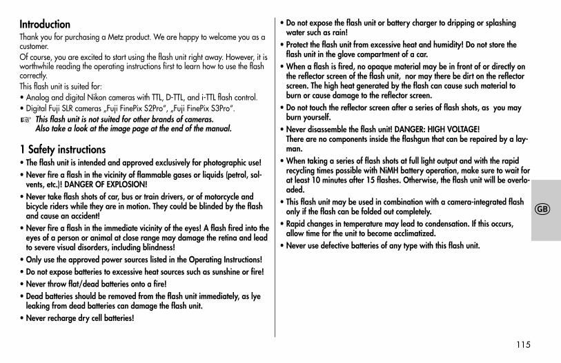
IntroductionThank you for purchasing a Metz product. We are happy to welcome you as acustomer.Of course, you are excited to start using the flash unit right away. However, it isworthwhile reading the operating instructions first to learn how to use the flashcorrectly.This flash unit is suited for:• Analog and digital Nikon cameras with TTL, D-TTL, and i-TTL flash control.• Digital Fuji SLR cameras „Fuji FinePix S2Pro“, „Fuji FinePix S3Pro“.
This flash unit is not suited for other brands of cameras.Also take a look at the image page at the end of the manual.
1 Safety instructions• The flash unit is intended and approved exclusively for photographic use!• Never fire a flash in the vicinity of flammable gases or liquids (petrol, sol-
vents, etc.)! DANGER OF EXPLOSION!• Never take flash shots of car, bus or train drivers, or of motorcycle and
bicycle riders while they are in motion. They could be blinded by the flashand cause an accident!
• Never fire a flash in the immediate vicinity of the eyes! A flash fired into theeyes of a person or animal at close range may damage the retina and leadto severe visual disorders, including blindness!
• Only use the approved power sources listed in the Operating Instructions!• Do not expose batteries to excessive heat sources such as sunshine or fire!• Never throw flat/dead batteries onto a fire!• Dead batteries should be removed from the flash unit immediately, as lye
leaking from dead batteries can damage the flash unit.• Never recharge dry cell batteries!
☞
• Do not expose the flash unit or battery charger to dripping or splashingwater such as rain!
• Protect the flash unit from excessive heat and humidity! Do not store theflash unit in the glove compartment of a car.
• When a flash is fired, no opaque material may be in front of or directly onthe reflector screen of the flash unit, nor may there be dirt on the reflectorscreen. The high heat generated by the flash can cause such material toburn or cause damage to the reflector screen.
• Do not touch the reflector screen after a series of flash shots, as you mayburn yourself.
• Never disassemble the flash unit! DANGER: HIGH VOLTAGE!There are no components inside the flashgun that can be repaired by a lay-man.
• When taking a series of flash shots at full light output and with the rapidrecycling times possible with NiMH battery operation, make sure to wait forat least 10 minutes after 15 flashes. Otherwise, the flash unit will be overlo-aded.
• This flash unit may be used in combination with a camera-integrated flashonly if the flash can be folded out completely.
• Rapid changes in temperature may lead to condensation. If this occurs,allow time for the unit to become acclimatized.
• Never use defective batteries of any type with this flash unit.
709 47 0159.A1 58AF-2 Ni Print 26.07.2010 14:13 Uhr Seite 115
116
�
2 Dedicated flash functionsDedicated flash functions are flash functions that have been specially adapted toa given camera system. Depending on the type of camera, different flash func-tions are supported.
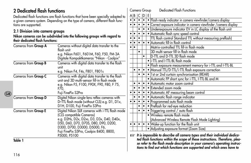
2.1 Division into camera groupsNikon cameras can be subdivided into the following groups with regard totheir dedicated flash functions:Cameras from Group A Cameras without digital data transfer to the
flash unite.g. Nikon F601, F601M, F60, F50, FM-3ADigitale Kompaktkameras “Nikon - Coolpix”
Cameras from Group B Cameras with digital data transfer to the flashunite.g. Nikon F4, F4s, F801, F801s
Cameras from Group C Cameras with digital data transfer to the flashunit and 3D multi-sensor fill-in flash modee.g. Nikon F5, F100, F90X, F90, F80, F 75,F70,Fuji FinePix S2Pro
Cameras from Group D Digital Nikon single-lens reflex cameras withD–TTL flash mode (without CLS) e.g. D1, D1x,D1H, D100, Fuji FinePix S3Pro
Cameras from Group E Digital Nikon SLR cameras with i-TTL flash mode(CLS compatible Cameras)e.g. D2Hs, D2x, D2xs, D3, D3x, D40, D40x,D50, D60, D70, D70S, D80, D90, D200,D300, D700, D3000, D5000, F6, Fuji FinePix S5Pro, Coolpix 8400, 8800,P5000, P5100
Table 1
Camera Group Dedicated Flash FunctionsA B C D E• • • • • Flash-ready indicator in camera viewfinder/camera display• • • • • Correct exposure indicator in camera viewfinder /camera display
• • • Underexposure indicator EV in LC display of the flash unit• • • • • Automatic flash sync speed control• • • TTL flash control Standard TTL without measuring preflash)• • • • • Automatic fill-in flash control• • Matrix-controlled TTL fill-in flash mode
• 3D multi-sensor fill-in flash mode• D-TTL and D-TTL 3D flash mode
• i-TTL and I-TTL-BL flash mode• Flash exposure measurement memory for i-TTL and I-TTL-BL
• • • • Manual TTL/D-TTL/i-TTL flash exposure correction• • • 1st or 2nd curtain synchronisation (REAR)
• Automatic FP short sync for i-TTL, I-TTL-BL and M• • • • Automatic motor zoom control• • • • Extended zoom mode
• • • • • Automatic AF measuring beam control• • • • Automatic flash range indicator
• • • • • Programmed auto flash mode• • • Preflash for red-eye reduction• • • Triggering control / auto flash
• Wireless remote flash mode (Advanced Wireless Remote Flash Mode Lighting)
• • • • • Wake-up function for the flash unit• Adjusting exposure format (Zoom Size)
It is impossible to describe all camera types and their individual dedica-ted flash functions within the scope of these instructions. Therefore, plea-se refer to the flash mode description in your camera’s operating instruc-tions to find out which functions are supported and which ones have to
☞
709 47 0159.A1 58AF-2 Ni Print 26.07.2010 14:13 Uhr Seite 116
117
�
be set manually on the camera. Using lenses not equipped with a CPU(i.e., lenses without auto focus mode), results in certain functional limita-tions.
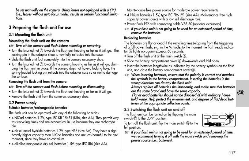
3 Preparing the flash unit for use3.1 Mounting the flash unitMounting the flash unit on the camera
Turn off the camera and flash before mounting or removing.• Turn the knurled nut � towards the flash unit housing as far as it will go. The
locking pin in the adapter shoe is now fully retracted into the case.• Slide the flash unit foot completely into the camera accessory shoe.• Turn the knurled nut � towards the camera housing as far as it will go, clam-
ping the flash unit in place. If the camera does not have a locking hole, thespring-loaded locking pin retracts into the adapter case so as not to damagethe surface.
Removing the flash unit from the cameraTurn off the camera and flash before mounting or dismounting.
• Turn the knurled nut � towards the flash unit housing as far as it will go.• Remove the flash unit from the camera’s accessory shoe.
3.2 Power supplySuitable batteries/rechargeable batteriesThe flash unit can be operated with any of the following batteries:• 4 NiCad batteries 1.2V, type IEC KR 15/51 (KR6, size AA). They permit very
fast recycling times and are economical in use because they are rechargea-ble.
• 4 nickel-metal-hydride batteries 1.2V, type HR6 (size AA). They have a signi-ficantly higher capacity than NiCad batteries and are less harmful to the envi-ronment, since they have no cadmium.
• 4 alkaline-manganese dry cell batteries 1.5V, type IEC LR6 (size AA).
☞
☞
Maintenance-free power source for moderate power requirements.• 4 lithium batteries 1.5V, type IEC FR6 L91 (size AA). Maintenance-free high-
capacity power source with a low self-discharge rate.• Power Pack P76 with connecting cable V58-50 (optional accessory)
If your flash unit is not going to be used for an extended period of time,remove the batteries.
Replacing batteriesThe batteries are flat or dead if the recycling time (elapsing from the triggeringof a full-power flash, e.g. in the M mode, to the moment the flash ready indica-tor � lights up again) exceeds 60 seconds.• Turn off the flash unit at the main switch �.• Slide the battery compartment cover � downwards and fold open.• Insert the batteries lengthwise as indicated by the battery symbols on the flash
unit, and close the battery compartment cover �.When inserting batteries, ensure that the polarity is correct and matchesthe symbols in the battery compartment. Inserting the batteries in thewrong direction can destroy the flash unit!Always replace all batteries simultaneously, and make sure that batteriesare the same brand and have the same capacity.Flat or dead batteries should not be disposed of with ordinary house-hold waste. Help protect the environment, and dispose of flat/dead bat-teries at the appropriate collection points.
3.3 Switching the flash unit on and offThe flash unit can be turned on by flipping the mainswitch � to the „ON“ position. To turn off the flash unit, flip the main switch � to theleft position.
If your flash unit is not going to be used for an extended period of time,we recommend turning it off with the main switch and removing thepower source (i.e., batteries).
☞
☞
☞
✴
709 47 0159.A1 58AF-2 Ni Print 26.07.2010 14:13 Uhr Seite 117
118
�
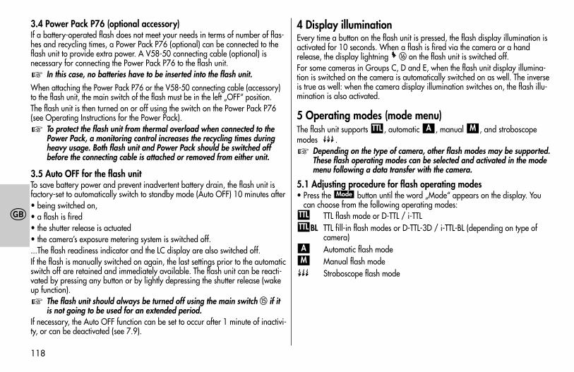
3.4 Power Pack P76 (optional accessory)If a battery-operated flash does not meet your needs in terms of number of flas-hes and recycling times, a Power Pack P76 (optional) can be connected to theflash unit to provide extra power. A V58-50 connecting cable (optional) isnecessary for connecting the Power Pack P76 to the flash unit.
In this case, no batteries have to be inserted into the flash unit.
When attaching the Power Pack P76 or the V58-50 connecting cable (accessory)to the flash unit, the main switch of the flash must be in the left „OFF“ position.The flash unit is then turned on or off using the switch on the Power Pack P76(see Operating Instructions for the Power Pack).
To protect the flash unit from thermal overload when connected to thePower Pack, a monitoring control increases the recycling times duringheavy usage. Both flash unit and Power Pack should be switched offbefore the connecting cable is attached or removed from either unit.
3.5 Auto OFF for the flash unit To save battery power and prevent inadvertent battery drain, the flash unit isfactory-set to automatically switch to standby mode (Auto OFF) 10 minutes after• being switched on,• a flash is fired• the shutter release is actuated• the camera’s exposure metering system is switched off....The flash readiness indicator and the LC display are also switched off.If the flash is manually switched on again, the last settings prior to the automaticswitch off are retained and immediately available. The flash unit can be reacti-vated by pressing any button or by lightly depressing the shutter release (wakeup function).
The flash unit should always be turned off using the main switch � if itis not going to be used for an extended period.
If necessary, the Auto OFF function can be set to occur after 1 minute of inactivi-ty, or can be deactivated (see 7.9).
☞
☞
☞
4 Display illuminationEvery time a button on the flash unit is pressed, the flash display illumination isactivated for 10 seconds. When a flash is fired via the camera or a handrelease, the display lightning � on the flash unit is switched off.For some cameras in Groups C, D and E, when the flash unit display illumina-tion is switched on the camera is automatically switched on as well. The inverseis true as well: when the camera display illumination switches on, the flash illu-mination is also activated.
5 Operating modes (mode menu)The flash unit supports , automatic , manual , and stroboscopemodes .
Depending on the type of camera, other flash modes may be supported.These flash operating modes can be selected and activated in the modemenu following a data transfer with the camera.
5.1 Adjusting procedure for flash operating modes• Press the button until the word „Mode“ appears on the display. You
can choose from the following operating modes:TTL flash mode or D-TTL / i-TTL
BL TTL fill-in flash modes or D-TTL-3D / i-TTL-BL (depending on type ofcamera)Automatic flash modeManual flash modeStroboscope flash mode
MA
TTLTTL
Mode
☞
MATTL
709 47 0159.A1 58AF-2 Ni Print 26.07.2010 14:13 Uhr Seite 118
119
�
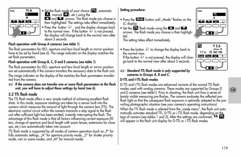
• Set the flash mode of your choice ( , automatic, manual l, etc.) using theand arrows. The flash mode you choose is
then highlighted. The settings take effect immediately.• Press the button , and the display changes back
to the normal view. If the button is not pressed,the display will change back to the normal view afterabout 5 seconds.
Flash operation with Group A cameras (see table 1)The flash parameters for ISO, aperture and lens focal length or mirror positionhave to be set by hand (see 6). The range indicator on the display matches theset flash parameters.Flash operation with Group B, C, D and E cameras (see table 1)The flash parameters for ISO, aperture and lens focal length or mirror positionare set automatically if the camera transfers the necessary data to the flash unit.The range indicator on the display of the matches the flash parameters transfer-red from the camera.
If the camera does not transfer one or more flash parameters to the flashunit, you will have to adjust these settings by hand (see 6).
5.2 TTL flash modeThe TTL flash mode offers a very simple method of achieving excellent flashshots. In this mode, exposure readings are taken by a sensor built into thecamera which measures the amount of light through the camera lens (TTL). Theelectronic control circuit within the camera transmits a stop signal to the flashunit after sufficient light has been emitted, instantly interrupting the flash. Theadvantage of this flash mode is that all factors influencing correct exposure (fil-ters, change of aperture and focal length with zoom lenses, extensions for close-ups, etc.) are automatically taken into account.TTL flash mode is supported by all modes of camera operation (such as „P“ forfully automatic settings, „A“ for aperture priority mode, „S“ for shutter prioritymode, vari or scene modes, and „M“ for manual mode).
☞
��MA
TTL Setting procedure:
• Press the button until „Mode“ flashes on theLC display.
• Set the flash mode using the and arrows. The flash mode you choose is then highligh-ted. The setting takes effect immediately.
• Press the button to change the display back tothe normal view.If the button is not pressed, the display will chan-ge back to the normal view after about 5 seconds.
Standard TTL flash mode is only supported bycameras in Groups A, B and C.
D-TTL and I-TTL flash modesD-TTL and I-TTL flash modes are advanced variants of the normal TTL flashmodes used with analog cameras. These modes are supported by Groups Dand E cameras (see table1). Prior to shooting, the flash unit fires a series ofbarely visible measuring pre-flashes. The camera evaluates the reflected pre-flash light so that the subsequent flash exposure is optimally adapted to the pre-vailing photographic situation (see your camera’s operating instructions).When the TTL flash mode is selected from the „mode menu“, the flash unit auto-matically activates standard TTL, D-TTL or i-TTL flash mode, depending on thetype of camera (see tables 1 and 2). After the settings are confirmed, will appear in the flash unit display for D-TTL or i-TTL flash modes.
TTL
☞
��TTL
Mode
Mode TTL BLAM
� � Set
A☛
Mode Para Sel
F 5.6AZoom 28
7.7 m ISO 100
TTL
Mode
AA
� � Set
TTL
☛
709 47 0159.A1 58AF-2 Ni Print 26.07.2010 14:13 Uhr Seite 119
120
�
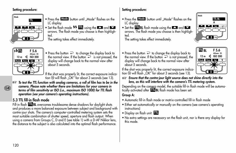
Setting procedure:
• Press the button until „Mode“ flashes on theLC display.
• Set the flash mode using the and arrows. The flash mode you choose is then highligh-ted. The setting takes effect immediately.
• Press the button to change the display back tothe normal view. If the button is not pressed, thedisplay will change back to the normal view afterabout 5 seconds.
If the shot was properly lit, the correct exposure indica-tion � will flash „OK“ for about 3 seconds (see 13).
To test the TTL function with analog cameras, a roll of film has to be in thecamera. Please note whether there are limitations for your camera interms of film sensitivity or ISO (i.e., maximum ISO 1000) for TTL flashoperation (see your camera’s operating instructions).
5.3 TTL fill-in flash modeFill-in flash BL overcomes troublesome dense shadows for daylight shotsand produces a more balanced exposure between subject and background withcontre-jour shots. The camera’s computer-controlled metering system sets themost suitable combination of shutter speed, aperture and flash output. Whenusing a camera from Groups C, D and E (see table 1) with a D-AF Nikkor lens,the distance to the subject is also calculated into the optimal flash performance.
TTL
☞
��TTL
Mode
Setting procedure:
• Press the button until „Mode“ flashes on theLC display.
• Set the BL flash mode using the and arrows. The flash mode you choose is then highligh-ted. The setting takes effect immediately.
• Press the button to change the display back tothe normal view. If the button is not pressed, thedisplay will change back to the normal view afterabout 5 seconds.
If the shot was properly lit, the correct exposure indica-tion � will flash „OK“ for about 3 seconds (see 13).
Ensure that the contre-jour light source does not shine directly into thelens, as this will interfere with the camera’s TTL metering system.
Depending on the camera model, the suitable fill-in flash mode will be automa-tically activated after BL flash mode has been set: Group A:• Automatic fill-in flash mode or matrix-controlled fill-in flash mode• Either set automatically or manually on the camera (see camera’s operating
instructions)• Display on flash unit: • No extra settings are necessary on the flash unit, nor is there any display for
this mode.
TTL
TTL
☞
��TTL
ModeMode
AA
� � Set
TTL
☛
Mode Para Sel
F 5.6AZoom 35
12 m ISO 200
TTL
✴
Mode
AA
� � Set
TTL BL
☛
Mode Para Sel
BL F 5.6AZoom 35
12 m ISO 200
TTL
✴
709 47 0159.A1 58AF-2 Ni Print 26.07.2010 14:13 Uhr Seite 120
121
�
Group B:• Matrix-controlled fill-in flash mode.• Settings made on flash unit.• Display on flash unit after saving: BLGroup C:• 3D multi-sensor fill-in flash mode.• Settings made on flash unit.• Display on flash unit after saving: BLGroup D:• D-TTL 3D flash mode.• Settings made on flash unit.• Display on flash unit after saving: BLGroup E:• i-TTL BL flash mode (not with Coolpix cameras).• Settings made on flash unit.• Display on flash unit after saving: BL
Some cameras do not support TTL fill-in flash mode in combination withSPOT exposure metering. This flash mode will then either be automati-cally cancelled or cannot be activated in the first place. In this case, nor-mal TTL flash mode, D-TTL or i-TTL modes will be set (see camera’s opera-ting instructions).
☞TTL
TTL
TTL
TTL
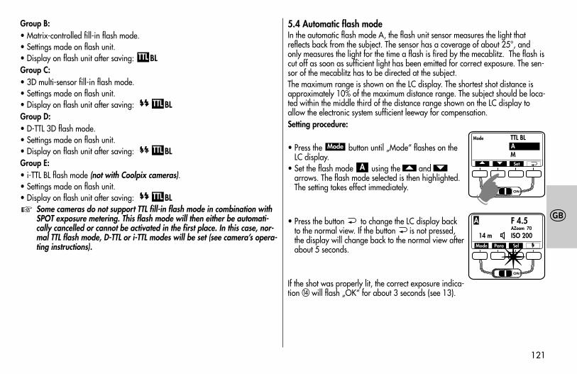
5.4 Automatic flash modeIn the automatic flash mode A, the flash unit sensor measures the light thatreflects back from the subject. The sensor has a coverage of about 25°, andonly measures the light for the time a flash is fired by the mecablitz. The flash iscut off as soon as sufficient light has been emitted for correct exposure. The sen-sor of the mecablitz has to be directed at the subject.The maximum range is shown on the LC display. The shortest shot distance isapproximately 10% of the maximum distance range. The subject should be loca-ted within the middle third of the distance range shown on the LC display toallow the electronic system sufficient leeway for compensation. Setting procedure:
• Press the button until „Mode“ flashes on theLC display.
• Set the flash mode using the and arrows. The flash mode selected is then highlighted.The setting takes effect immediately.
• Press the button to change the LC display backto the normal view. If the button is not pressed,the display will change back to the normal view afterabout 5 seconds.
If the shot was properly lit, the correct exposure indica-tion � will flash „OK“ for about 3 seconds (see 13).
��A
ModeMode TTL BL
AM
� � Set
A
☛
Mode Para Sel
F 4.5AZoom 70
14 m ISO 200
A
✴
709 47 0159.A1 58AF-2 Ni Print 26.07.2010 14:13 Uhr Seite 121
122
�
5.5 Automatic fill-in flash modeWhen shooting in automatic fill-in flash mode in daylight, the automatic flashmode will automatically set a correction of between -1 and -2 f-stops tocompensate for flash exposures (see 6.4 and 10.5).This has a graduated lightening effect on shadowy areas, which has a naturalappearance on the photograph.
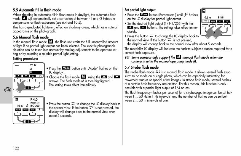
5.6 Manual flash modeIn the manual flash mode , the flash unit emits the full uncontrolled amountof light if no partial light output has been selected. The specific photographicsituation can be taken into account by making adjustments to the aperture set-ting or by selecting a suitable partial light setting.Setting procedure:
• Press the button until „Mode“ flashes on theLC display.
• Choose the flash mode using the and arrows. The flash mode M is then highlighted. The setting takes effect immediately.
• Press the button to change the LC display back tothe normal view. If the button is not pressed, thedisplay will change back to the normal view afterabout 5 seconds.
��M
Mode
M
A
Set partial light output:• Press the button (Parameters ) until „P“ flashes
on the LC display for partial light output.• Set the desired light output (1/1-1/256) with the
and buttons. The setting takes effect imme-diately.
• Press the button to change the LC display back tothe normal view. If the button is not pressed, the display will change back to the normal view after about 5 seconds.
The mecablitz LC display will indicate the flash-to-subject distance required for acorrect flash exposure.
Some cameras only support the manual flash mode when thecamera is set to the manual operating mode M.
5.7 Strobe flash modeThe strobe flash mode is a manual flash mode. It allows several flash expo-sures to be made on a single photo, which can be especially interesting formovement studies or special effect images. In strobe flash mode, several flashesat a certain flash frequency are emitted. For this reason, this function is onlypossible with a partial light output of 1/4 or less. The flash frequency (flashes per second) for a stroboscope image can be set bet-ween 1 ... 50 Hz in 1 Hz intervals, and the number of flashes can be set bet-ween 2 ... 50 in intervals of one.
M☞
–+
Para
Mode TTL BLAM
� � Set
M
☛
Mode Para Sel
F 4.0MZoom 24
10 m ISO 200
M
F 4.0MZoom 24
0,6 m P1/8
M
☛☛
Para – +
709 47 0159.A1 58AF-2 Ni Print 26.07.2010 14:13 Uhr Seite 122
123
�
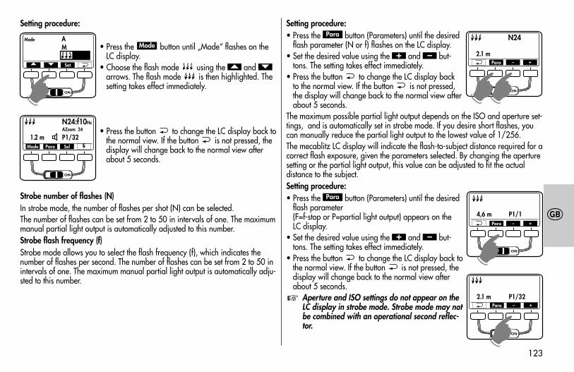
Setting procedure:
• Press the button until „Mode“ flashes on theLC display.
• Choose the flash mode using the and arrows. The flash mode is then highlighted. Thesetting takes effect immediately.
• Press the button to change the LC display back tothe normal view. If the button is not pressed, thedisplay will change back to the normal view afterabout 5 seconds.
Strobe number of flashes (N)In strobe mode, the number of flashes per shot (N) can be selected.The number of flashes can be set from 2 to 50 in intervals of one. The maximummanual partial light output is automatically adjusted to this number.Strobe flash frequency (f)Strobe mode allows you to select the flash frequency (f), which indicates thenumber of flashes per second. The number of flashes can be set from 2 to 50 inintervals of one. The maximum manual partial light output is automatically adju-sted to this number.
��
Mode
Setting procedure:• Press the button (Parameters) until the desired
flash parameter (N or f) flashes on the LC display.• Set the desired value using the and but-
tons. The setting takes effect immediately.• Press the button to change the LC display back
to the normal view. If the button is not pressed,the display will change back to the normal view afterabout 5 seconds.
The maximum possible partial light output depends on the ISO and aperture set-tings, and is automatically set in strobe mode. If you desire short flashes, youcan manually reduce the partial light output to the lowest value of 1/256.The mecablitz LC display will indicate the flash-to-subject distance required for acorrect flash exposure, given the parameters selected. By changing the aperturesetting or the partial light output, this value can be adjusted to fit the actualdistance to the subject.Setting procedure:• Press the button (Parameters) until the desired
flash parameter (F=f-stop or P=partial light output) appears on the LC display.
• Set the desired value using the and but-tons. The setting takes effect immediately.
• Press the button to change the LC display back tothe normal view. If the button is not pressed, thedisplay will change back to the normal view afterabout 5 seconds.
Aperture and ISO settings do not appear on theLC display in strobe mode. Strobe mode may notbe combined with an operational second reflec-tor.
☞
–+
Para
–+
ParaMode A
M
� � Set
☛
Mode Para Sel
N24:f10HzAZoom 24
1.2 m P1/32
Para – +
N24
2.1 m
☛☛
Para – +
2.1 m P1/32
F 4.0MZoom 24
4,6 m P1/1
☛☛
Para – +
709 47 0159.A1 58AF-2 Ni Print 26.07.2010 14:13 Uhr Seite 123
124
�
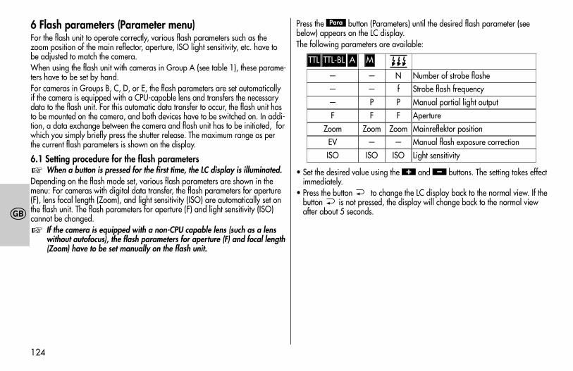
6 Flash parameters (Parameter menu)For the flash unit to operate correctly, various flash parameters such as thezoom position of the main reflector, aperture, ISO light sensitivity, etc. have tobe adjusted to match the camera.When using the flash unit with cameras in Group A (see table 1), these parame-ters have to be set by hand.For cameras in Groups B, C, D, or E, the flash parameters are set automaticallyif the camera is equipped with a CPU-capable lens and transfers the necessarydata to the flash unit. For this automatic data transfer to occur, the flash unit hasto be mounted on the camera, and both devices have to be switched on. In addi-tion, a data exchange between the camera and flash unit has to be initiated, forwhich you simply briefly press the shutter release. The maximum range as perthe current flash parameters is shown on the display.
6.1 Setting procedure for the flash parametersWhen a button is pressed for the first time, the LC display is illuminated.
Depending on the flash mode set, various flash parameters are shown in themenu: For cameras with digital data transfer, the flash parameters for aperture(F), lens focal length (Zoom), and light sensitivity (ISO) are automatically set onthe flash unit. The flash parameters for aperture (F) and light sensitivity (ISO)cannot be changed.
If the camera is equipped with a non-CPU capable lens (such as a lenswithout autofocus), the flash parameters for aperture (F) and focal length(Zoom) have to be set manually on the flash unit.
☞
☞
Press the button (Parameters) until the desired flash parameter (seebelow) appears on the LC display.The following parameters are available:
• Set the desired value using the and buttons. The setting takes effectimmediately.
• Press the button to change the LC display back to the normal view. If thebutton is not pressed, the display will change back to the normal viewafter about 5 seconds.
–+
Para
TTL TTL-BL A M
———F
ZoomEVISO
——PF
Zoom—
ISO
N Number of strobe flasheStrobe flash frequencyManual partial light outputApertureMainreflektor positionManual flash exposure correctionLight sensitivity
fPF
Zoom—
ISO
709 47 0159.A1 58AF-2 Ni Print 26.07.2010 14:13 Uhr Seite 124
125
�
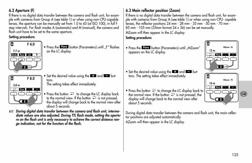
6.2 Aperture (F)If there is no digital data transfer between the camera and flash unit, for exam-ple with cameras from Group A (see table 1) or when using non-CPU-capablelenses, the aperture can be manually set from 1.0 to 45 (at ISO 100), in full f-stop intervals. For flash modes A (automatic) and M (manual), the camera andflash unit have to be set to the same aperture.Setting procedure:
• Press the button (Parameters) until „F“ flasheson the LC display.
• Set the desired value using the and but-tons. The setting takes effect immediately.
• Press the button to change the LC display backto the normal view. If the button is not pressed,the display will change back to the normal view afterabout 5 seconds.
During digital data transfer between the camera and flash unit, interme-diate values are also adjusted. During TTL flash mode, setting the apertu-re on the flash unit is only necessary to achieve the correct distance ran-ge indication, not for the function of the flash.
☞
–+
Para
6.3 Main reflector position (Zoom)If there is no digital data transfer between the camera and flash unit, for exam-ple with cameras from Group A (see table 1) or when using non-CPU- capablelenses, the reflector positions 24 mm - 28 mm - 35 mm - 50 mm - 70 mm - 85 mm - 105 mm (35mm format 24 x 36) can be set manually.MZoom will then appear in the LC display. Setting procedure:
• Press the button (Parameters) until „MZoom“appears on the LC display.
• Set the desired value using the and but-tons. The setting takes effect immediately.
• Press the button to change the LC display back tothe normal view. If the button is not pressed, thedisplay will change back to the normal view afterabout 5 seconds.
During digital data transfer between the camera and flash unit, the main reflec-tor positions are adjusted automatically.AZoom will then appear in the LC display.
–+
Para
Mode Para Sel
F 4.0AZoom 70
7,7 m ISO 200
A
F 8.0AZoom 70
3,8 m ISO 200
A
☛
Para – +
☛
F 8.0MZoom 70
16 m ISO 200
A
Para – +
☛
F 8.0MZoom 35
12 m ISO 200
A
Para – +
☛
709 47 0159.A1 58AF-2 Ni Print 26.07.2010 14:13 Uhr Seite 125
126
�
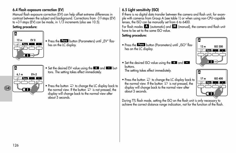
6.4 Flash exposure correction (EV)Manual flash exposure correction (EV) can help offset extreme differences incontrast between the subject and background. Corrections from -3 f-stops (EV)to +3 f-stops (EV) can be made, in 1/3 increments (also see 10.5).Setting procedure:
• Press the button (Parameters) until „EV“ flas-hes on the LC display.
• Set the desired EV value using the and but-tons. The setting takes effect immediately.
• Press the button to change the LC display back tothe normal view. If the button is not pressed, thedisplay will change back to the normal view afterabout 5 seconds.
–+
Para
6.5 Light sensitivity (ISO)If there is no digital data transfer between the camera and flash unit, for exam-ple with cameras from Group A (see table 1) or when using non-CPU–capablelenses, the ISO can be manually set from 6 to 6400.For flash modes (automatic) and (manual), the camera and flash unithave to be set to the same ISO value. Setting procedure:
• Press the button (Parameters) until „ISO“ flas-hes on the LC display.
• Set the desired ISO value using the and buttons. The setting takes effect immediately.
• Press the button to change the LC display back tothe normal view. If the button is not pressed, thedisplay will change back to the normal view afterabout 5 seconds.
During TTL flash mode, setting the ISO on the flash unit is only necessary toachieve the correct distance range indication, not for the function of the flash.
–+
Para
MA
F 8.0MZoom 35
12 m EV 0
A
Para – +
☛
F 8.0MZoom 35
6,1 m EV+2
A
Para – +
☛
F 8.0MZoom 35
17 m ISO 400
A
Para – +
☛
F 8.0MZoom 35
12 m ISO 200
A
Para – +
☛
709 47 0159.A1 58AF-2 Ni Print 26.07.2010 14:13 Uhr Seite 126
127
�
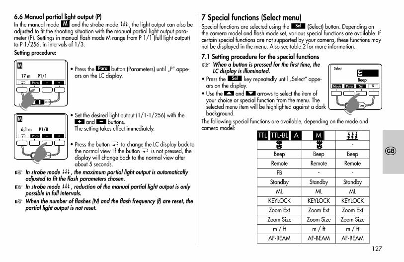
6.6 Manual partial light output (P)In the manual mode and the strobe mode , the light output can also beadjusted to fit the shooting situation with the manual partial light output para-meter (P). Settings in manual flash mode M range from P 1/1 (full light output)to P 1/256, in intervals of 1/3.Setting procedure:
• Press the button (Parameters) until „P“ appe-ars on the LC display.
• Set the desired light output (1/1-1/256) with theand buttons.
The setting takes effect immediately.
• Press the button to change the LC display back tothe normal view. If the button is not pressed, thedisplay will change back to the normal view afterabout 5 seconds.
In strobe mode , the maximum partial light output is automaticallyadjusted to fit the flash parameters chosen.In strobe mode , reduction of the manual partial light output is onlypossible in full intervals.When the number of flashes (N) and the flash frequency (f) are reset, thepartial light output is not reset.
☞
☞
☞
–+
Para
M7 Special functions (Select menu)Special functions are selected using the (Select) button. Depending onthe camera model and flash mode set, various special functions are available. Ifcertain special functions are not supported by your camera, these functions maynot be displayed in the menu. Also see table 2 for more information.
7.1 Setting procedure for the special functionsWhen a button is pressed for the first time, theLC display is illuminated.
• Press the key repeatedly until „Select“ appe-ars on the display.
• Use the and arrows to select the item ofyour choice or special function from the menu. Theselected menu item will be highlighted against a darkbackground.
The following special functions are available, depending on the mode andcamera model:
��
Sel
☞
Sel
F 8.0MZoom 35
6,1 m P1/8
M
Para – +
☛F 8.0MZoom 35
17 m P1/1
M
Para – +
☛
Select
BeepMode Para Sel
☛
TTL TTL-BL A M
Beep
FB
Zoom Ext
Remote
Zoom Size
MLStandby
KEYLOCK
Beep
-
Zoom Ext
Remote
Zoom Size
MLStandby
KEYLOCK
Beep
-
Zoom Ext
Remote
Zoom Sizem / ft m / ft m / ft
AF-BEAM AF-BEAM AF-BEAM
-
MLStandby
KEYLOCK
709 47 0159.A1 58AF-2 Ni Print 26.07.2010 14:13 Uhr Seite 127
128
�
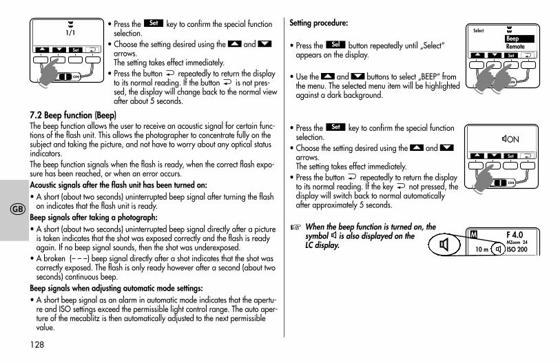
• Press the key to confirm the special functionselection.
• Choose the setting desired using the and arrows. The setting takes effect immediately.
• Press the button repeatedly to return the displayto its normal reading. If the button is not pres-sed, the display will change back to the normal viewafter about 5 seconds.
7.2 Beep function (Beep)The beep function allows the user to receive an acoustic signal for certain func-tions of the flash unit. This allows the photographer to concentrate fully on thesubject and taking the picture, and not have to worry about any optical statusindicators.The beep function signals when the flash is ready, when the correct flash expo-sure has been reached, or when an error occurs.Acoustic signals after the flash unit has been turned on:• A short (about two seconds) uninterrupted beep signal after turning the flash
on indicates that the flash unit is ready.Beep signals after taking a photograph:• A short (about two seconds) uninterrupted beep signal directly after a picture
is taken indicates that the shot was exposed correctly and the flash is readyagain. If no beep signal sounds, then the shot was underexposed.
• A broken (– – –) beep signal directly after a shot indicates that the shot wascorrectly exposed. The flash is only ready however after a second (about twoseconds) continuous beep.
Beep signals when adjusting automatic mode settings:• A short beep signal as an alarm in automatic mode indicates that the apertu-
re and ISO settings exceed the permissible light control range. The auto aper-ture of the mecablitz is then automatically adjusted to the next permissiblevalue.
��
Set Setting procedure:
• Press the button repeatedly until „Select“appears on the display.
• Use the and buttons to select „BEEP“ fromthe menu. The selected menu item will be highlightedagainst a dark background.
• Press the key to confirm the special functionselection.
• Choose the setting desired using the and arrows. The setting takes effect immediately.
• Press the button repeatedly to return the displayto its normal reading. If the key not pressed, thedisplay will switch back to normal automaticallyafter approximately 5 seconds.
When the beep function is turned on, thesymbol is also displayed on theLC display.
☞
��
Set
��
Sel
1/1
� � Set☛
Select
RemoteBeep
� � Set
☛☛
ON
� � Set
☛
F 4.0MZoom 24
10 m ISO 200
M
☛
709 47 0159.A1 58AF-2 Ni Print 26.07.2010 14:13 Uhr Seite 128
129
�
7.3 Flash Bracketing Series (FB)A series of flash exposures (flash-bracketing FB) can be carried out in the and automatic flash modes. A flash bracketing series consists ofthree successive flash shots with different flash exposure correction values.When a flash bracketing series is set, FB and the correction value appear on thedisplay. The possible correction values range from 1/3 to 3 apertures in one-third aperture increments.Setting procedure:
• Press the button repeatedly until „Select“appears on the display.
• Select the menu option „FB“ by pressing the and buttons. The selected menu option will behighlighted.
• Confirm the selection of the special function by pres-sing the button.
• Select the desired setting with the and but-tons. The setting takes effect immediately.
• Press the button repeatedly until the screen isreset to its normal view. If the button is not pres-sed, the display is automatically reset to its normalview after about 5 seconds.
��Set
��
Sel
ATTL
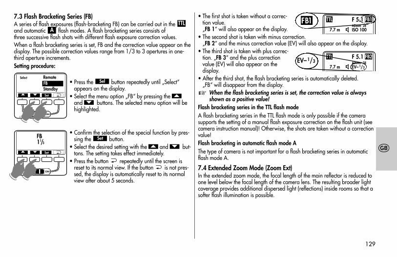
• The first shot is taken without a correc-tion value. „FB 1“ will also appear on the display.
• The second shot is taken with minus correction. „FB 2“ and the minus correction value (EV) will also appear on the display.
• The third shot is taken with plus correc-tion. „FB 3“ and the plus correctionvalue (EV) will also appear on thedisplay.
• After the third shot, the flash bracketing series is automatically deleted. „FB“ will disappear from the display.
When the flash bracketing series is set, the correction value is alwaysshown as a positive value!
Flash bracketing series in the TTL flash modeA flash bracketing series in the TTL flash mode is only possible if the camerasupports the setting of a manual flash exposure correction on the flash unit (seecamera instruction manual)! Otherwise, the shots are taken without a correctionvalue!Flash bracketing in automatic flash mode AThe type of camera is not important for a flash bracketing series in automaticflash mode A.
7.4 Extended Zoom Mode (Zoom Ext)In the extended zoom mode, the focal length of the main reflector is reduced toone level below the focal length of the camera lens. The resulting broader lightcoverage provides additional dispersed light (reflections) inside rooms so that asofter flash illumination is possible.
☞
Select Remote
StandbyFB
� � Set
☛☛
FB11/3
� � Set
☛☛F 5.1 AZoom 28
7.7 m ISO 100
FB1TTLFB1
F 5.1 AZoom 28
7.7 m EV–1/3
FB2TTLEV–1/3
709 47 0159.A1 58AF-2 Ni Print 26.07.2010 14:13 Uhr Seite 129
130
�
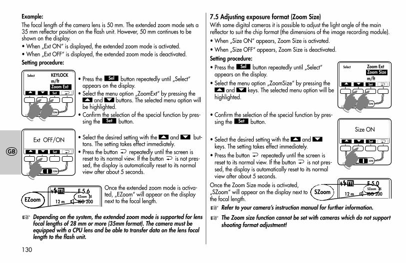
Example:The focal length of the camera lens is 50 mm. The extended zoom mode sets a35 mm reflector position on the flash unit. However, 50 mm continues to beshown on the display.• When „Ext ON“ is displayed, the extended zoom mode is activated.• When „Ext OFF“ is displayed, the extended zoom mode is deactivated.Setting procedure:
• Press the button repeatedly until „Select“appears on the display.
• Select the menu option „ZoomExt“ by pressing theand buttons. The selected menu option will
be highlighted.• Confirm the selection of the special function by pres-
sing the button.
• Select the desired setting with the and but-tons. The setting takes effect immediately.
• Press the button repeatedly until the screen isreset to its normal view. If the button is not pres-sed, the display is automatically reset to its normalview after about 5 seconds.
Once the extended zoom mode is activa-ted, „EZoom“ will appear on the displaynext to the focal length.
Depending on the system, the extended zoom mode is supported for lensfocal lengths of 28 mm or more (35mm format). The camera must beequipped with a CPU lens and be able to transfer data on the lens focallength to the flash unit.
☞
��
Set
��
Sel
7.5 Adjusting exposure format (Zoom Size)With some digital cameras it is possible to adjust the light angle of the mainreflector to suit the chip format (the dimensions of the image recording module).• When „Size ON“ appears, Zoom Size is activated.• When „Size OFF“ appears, Zoom Size is deactivated.Setting procedure:• Press the button repeatedly until „Select“
appears on the display.• Select the menu option „ZoomSize“ by pressing the
and keys. The selected menu option will behighlighted.
• Confirm the selection of the special function by pres-sing the button.
• Select the desired setting with the and keys. The setting takes effect immediately.
• Press the button repeatedly until the screen isreset to its normal view. If the button is not pres-sed, the display is automatically reset to its normalview after about 5 seconds.
Once the Zoom Size mode is activated,„SZoom“ will appear on the display next tothe focal length.
Refer to your camera’s instruction manual for further information.
The Zoom size function cannot be set with cameras which do not supportshooting format adjustment!
☞☞
��
Set
��
Sel
Select KEYLOCKm/ftZoom Ext
� � Set
☛☛
Ext OFF/ON
� � Set
☛
F 5.6EZoom 35
12 m ISO 200
TTL
EZoom
F 5.0SZoom 35
12 m ISO 200
TTL
SZoom
Select Zoom Ext
m/ftZoom Size
� � Set
☛☛
Size ON
� � Set
☛
709 47 0159.A1 58AF-2 Ni Print 26.07.2010 14:13 Uhr Seite 130
131
�
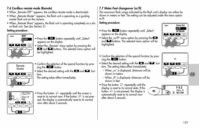
7.6 Cordless remote mode (Remote)• When „Remote OFF“ appears, the cordless remote mode is deactivated.• When „Remote Master“ appears, the flash unit is operating as a guiding
master flash unit on the camera.• When „Remote Slave“ appears, the flash unit is operating completely as a sla-
ve flash unit. See also Section 21.Setting procedure:
• Press the button repeatedly until „Select“appears on the display.
• Select the „Remote“ menu option by pressing theand buttons. The selected menu option will
be highlighted.
• Confirm the selection of the special function by pres-sing the button.
• Select the desired setting with the and but-tons. The setting takes effect immediately.
• Press the button repeatedly until the screen isreset to its normal view. If the button is not pres-sed, the display is automatically reset to its normalview after about 5 seconds.
��Set
��
Sel
7.7 Meter-Feet changeover (m/ft)The maximum flash range indicated by the flash unit’s display can either beshown in meters or feet. The setting can be adjusted under the menu optionm/ft. Setting procedure:
• Press the button repeatedly until „Select“appears on the display.
• Select the „m/ft“ menu option by pressing the and buttons. The selected menu option will behighlighted.
• Confirm the selection of the special function by pres-sing the button.
• Select the desired setting with the and but-tons. The setting takes effect immediately.– When „m“ is displayed, distances will be
shown in meters.– When „ft“ is displayed, distances will be
shown in feet.• Press the button repeatedly until the
display is reset to its normal state. If thebutton is not pressed, the display isautomatically reset to its normal viewafter about 5 seconds.
��Set
��
Sel
Select BEEP
FBRemote
� � Set
☛☛
RemoteMaster
� � Set
☛
Para Sel
CH1TTL AZoom 28
TTL+1/3 F32BAM
Select Zoom Ext
AF-BEAMm/ft
� � Set
☛☛
m� � Set
☛
F 4.5AZoom 70
14 m ISO 200
Am
709 47 0159.A1 58AF-2 Ni Print 26.07.2010 14:13 Uhr Seite 131
132
�
7.8 Secondary reflector The secondary reflector is used for frontal brightening in the case of indirect ligh-ting when the main reflector is pivoted to the side or upwards (see 10.3).If the secondary reflector produces too much light, it can be reduced to 1/2or 1/4 .• „ Off“ setting: Secondary reflector is turned off.• „ P1 / 1“ setting: secondary reflector is operating at full light output.• „ P1 / 2“ setting: secondary reflector is operating at 1/2 light output.• „ P1 / 4“ setting: secondary reflector is operating at 1/4 light output.When the secondary reflector is activated and the setting is saved, a symbol will appear in the display.Setting procedure:
• Press the button repeatedly until „Select“appears on the display.
• Select the menu option by pressing the andbuttons. The selected menu option will be high-
lighted.
• Confirm the selection of the special function by pres-sing the button.
• Select the desired setting with the and but-tons. The setting takes effect immediately.
• Press the button repeatedly until the display isreset to its normal state. If the button is not pres-sed, the display is automatically reset to its normal
view after about 5 seconds.Please also refer to the informationin Section 10.3!
☞
��Set
��
Sel
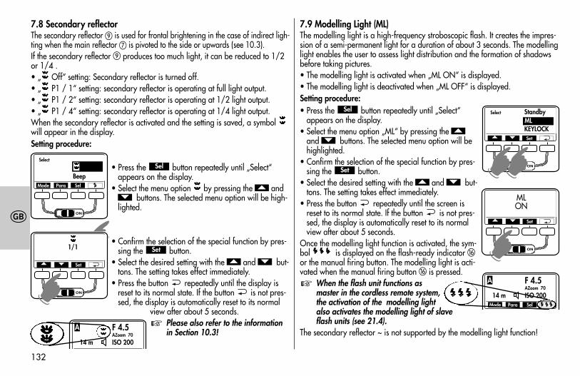
7.9 Modelling Light (ML)The modelling light is a high-frequency stroboscopic flash. It creates the impres-sion of a semi-permanent light for a duration of about 3 seconds. The modellinglight enables the user to assess light distribution and the formation of shadowsbefore taking pictures.• The modelling light is activated when „ML ON“ is displayed.• The modelling light is deactivated when „ML OFF“ is displayed. Setting procedure:• Press the button repeatedly until „Select“
appears on the display.• Select the menu option „ML“ by pressing the
and buttons. The selected menu option will behighlighted.
• Confirm the selection of the special function by pres-sing the button.
• Select the desired setting with the and but-tons. The setting takes effect immediately.
• Press the button repeatedly until the screen isreset to its normal state. If the button is not pres-sed, the display is automatically reset to its normalview after about 5 seconds.
Once the modelling light function is activated, the sym-bol is displayed on the flash-ready indicator �or the manual firing button. The modelling light is acti-vated when the manual firing button � is pressed.
When the flash unit functions asmaster in the cordless remote system,the activation of the modelling lightalso activates the modelling light of slaveflash units (see 21.4).
The secondary reflector ~ is not supported by the modelling light function!
☞
��Set
��
Sel
Select
BeepMode Para Sel
☛1/1
� � Set
☛
F 4.5AZoom 70
14 m ISO 200
A
Select Standby
KEYLOCKML
� � Set
☛☛
MLON
� � Set
☛
Mode Para Sel
F 4.5AZoom 70
14 m ISO 200
A
709 47 0159.A1 58AF-2 Ni Print 26.07.2010 14:13 Uhr Seite 132
133
�
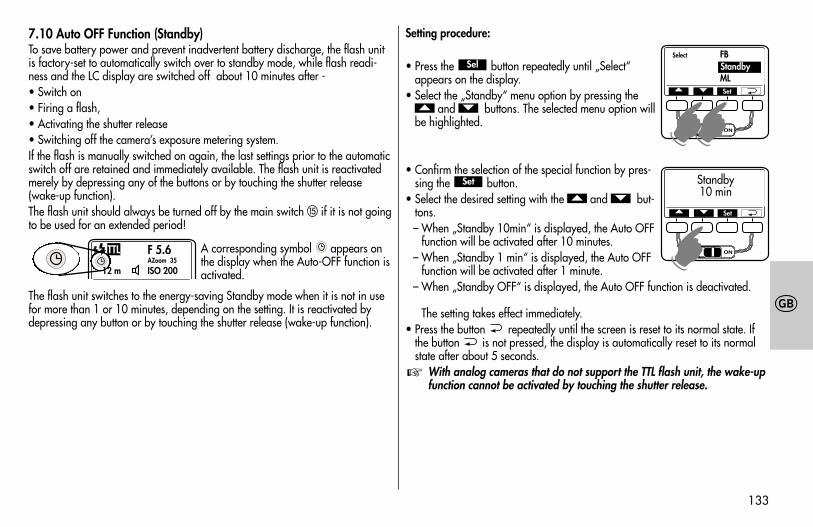
7.10 Auto OFF Function (Standby)To save battery power and prevent inadvertent battery discharge, the flash unitis factory-set to automatically switch over to standby mode, while flash readi-ness and the LC display are switched off about 10 minutes after -• Switch on• Firing a flash,• Activating the shutter release• Switching off the camera’s exposure metering system.If the flash is manually switched on again, the last settings prior to the automaticswitch off are retained and immediately available. The flash unit is reactivatedmerely by depressing any of the buttons or by touching the shutter release(wake-up function).The flash unit should always be turned off by the main switch � if it is not goingto be used for an extended period!
A corresponding symbol appears onthe display when the Auto-OFF function isactivated.
The flash unit switches to the energy-saving Standby mode when it is not in usefor more than 1 or 10 minutes, depending on the setting. It is reactivated bydepressing any button or by touching the shutter release (wake-up function).
Setting procedure:
• Press the button repeatedly until „Select“appears on the display.
• Select the „Standby“ menu option by pressing theand buttons. The selected menu option will
be highlighted.
• Confirm the selection of the special function by pres-sing the button.
• Select the desired setting with the and but-tons.– When „Standby 10min“ is displayed, the Auto OFF
function will be activated after 10 minutes.– When „Standby 1 min“ is displayed, the Auto OFF
function will be activated after 1 minute.– When „Standby OFF“ is displayed, the Auto OFF function is deactivated.
The setting takes effect immediately.• Press the button repeatedly until the screen is reset to its normal state. If
the button is not pressed, the display is automatically reset to its normalstate after about 5 seconds.
With analog cameras that do not support the TTL flash unit, the wake-upfunction cannot be activated by touching the shutter release.
☞
��Set
��
Sel
F 5.6AZoom 35
12 m ISO 200
TTL
Select FB
MLStandby
� � Set
☛☛
Standby10 min
� � Set
☛
709 47 0159.A1 58AF-2 Ni Print 26.07.2010 14:13 Uhr Seite 133
134
�
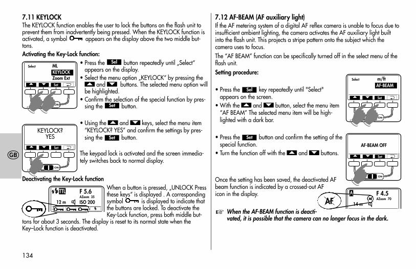
7.11 KEYLOCKThe KEYLOCK function enables the user to lock the buttons on the flash unit toprevent them from inadvertently being pressed. When the KEYLOCK function isactivated, a symbol appears on the display above the two middle but-tons.Activating the Key-Lock function:
• Press the button repeatedly until „Select“appears on the display.
• Select the menu option „KEYLOCK“ by pressing theand buttons. The selected menu option will
be highlighted. • Confirm the selection of the special function by pres-
sing the button.
• Using the and keys, select the menu item“KEYLOCK? YES” and confirm the settings by pres-sing the button.
The keypad lock is activated and the screen immedia-tely switches back to normal display.
Deactivating the Key-Lock functionWhen a button is pressed, „UNLOCK Pressthese keys“ is displayed . A correspondingsymbol is displayed to indicate thatthe buttons are locked. To deactivate theKey-Lock function, press both middle but-
tons for about 3 seconds. The display is reset to its normal state when theKey–Lock function is deactivated.
Set
��
Set
��
Sel
7.12 AF-BEAM (AF auxiliary light)If the AF metering system of a digital AF reflex camera is unable to focus due toinsufficient ambient lighting, the camera activates the AF auxiliary light builtinto the flash unit. This projects a stripe pattern onto the subject which thecamera uses to focus. The “AF BEAM” function can be specifically turned off in the select menu of theflash unit.Setting procedure:
• Press the key repeatedly until "Select" appears on the screen.
• With the and button, select the menu item“AF BEAM” The selected menu item will be high-lighted with a dark bar.
• Press the button and confirm the setting of thespecial function.
• Turn the function off with the and buttons.
Once the setting has been saved, the deactivated AFbeam function is indicated by a crossed-out AFicon in the display.
When the AF-BEAM function is deacti-vated, it is possible that the camera can no longer focus in the dark.
☞
��
Set
��
Sel
Select ML
Zoom ExtKEYLOCK
� � Set
☛☛
KEYLOCK?YES
� � Set
☛
F 5.6AZoom 35
12 m ISO 200
TTL
Select m/ftAF-BEAM
� � Set
☛☛
F 4.5AF AZoom 70
14 m
A
AF
AF-BEAM OFF
� � Set
☛
709 47 0159.A1 58AF-2 Ni Print 26.07.2010 14:13 Uhr Seite 134
135
�
8 Motor Zoom ReflectorThe zoom position of the main reflector can be adjusted for focal lengths of atleast 24 mm (35 mm format). For lenses with focal lengths of 12 mm or more,the integrated wide-angle diffuser � can be positioned over the main reflector.The following zoom positions are available:24 mm - 28 mm - 35 mm - 50 mm - 70 mm - 85 mm - 105 mm (correspondingto 35 mm format)
When using the wide-angle diffuser � the main reflector is automati-cally moved to the 24 mm position! Because of the wide-angle diffuser,12 mm appears on the display (see 9).
Automatic zoom adjustmentThe main reflector’s automatic zoom adjustment is supported by cameras fromGroups B, C, D and E when these are equipped with a CPU lens. The zoomposition automatically adjusts to the focal length of the lens. AZoom and theposition of the reflector (mm) are indicated on the flash unit’s display.Manual zoom adjustmentWhen the flash unit is used with a camera from Group A or a lens without aCPU, the zoom position of the main reflector must be set manually. MZoom isindicated on the display. Adjusting the setting - see 6.3
If you use a zoom-lens and do not necessarily need the full guide num-ber and maximum flash range of the flash unit you can leave the zoomreflector at the position for the shortest focal length of the zoom lens.This will provide full light coverage of the picture and eliminate the needto continually adjust it to the focal length of the lens.
Example:You use a zoom lens with a focal length range of 35 mm to 105 mm. In thiscase, set the position of the main reflector to 35 mm!
☞
☞
Manual adjustment of the zoom position with AZoomThe zoom position of the main reflector can also be changed when the flashunit is used with a camera capable of data transmission, in order to achievespecial lighting effects (such as hot-spot, etc.). See also 6.3.Once saved, „MZoom“ will be indicated on the display. Resetting to AZoom mode• Touch the shutter release to begin a data transfer between the flash unit and
the camera.• Continue changing the zoom position until AZoom appears on the display.
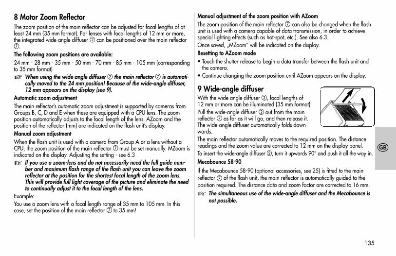
9 Wide-angle diffuserWith the wide angle diffuser �, focal lengths of12 mm or more can be illuminated (35 mm format).Pull the wide-angle diffuser � out from the mainreflector as far as it will go, and then release it. The wide-angle diffuser automatically folds down-wards.The main reflector automatically moves to the required position. The distancereadings and the zoom value are corrected to 12 mm on the display panel.To insert the wide-angle diffuser �, turn it upwards 90° and push it all the way in.Mecabounce 58-90If the Mecabounce 58-90 (optional accessories, see 25) is fitted to the mainreflector of the flash unit, the main reflector is automatically guided to theposition required. The distance data and zoom factor are corrected to 16 mm.
The simultaneous use of the wide-angle diffuser and the Mecabounce isnot possible.
☞
709 47 0159.A1 58AF-2 Ni Print 26.07.2010 14:13 Uhr Seite 135
136
�
10 Flash techniques10.1 Bounce flashBounce flash illuminates the subject more softly and reduces dense shadows. Italso reduces the drop in light from foreground to background that occurs forphysical reasons.The main reflector of the flash unit can be swivelled horizontally and tiltedvertically for bounce flash. To do this, depress the reflector unlocking button �and tilt the reflector . To avoid colour cast in your shots, the reflective surfaceshould be colour-neutral or white. For frontal fill-in lighting, the secondaryreflector can also be activated in the Select Menu (see 7.8).
When tilting the main reflector vertically, make sure that it is turnedthrough an angle that is wide enough to prevent direct light from fallingon the subject. The reflector should be tilted at least as far as the 60°lock-in position.
Flash ranges do not appear on the display when the main reflector is turned.
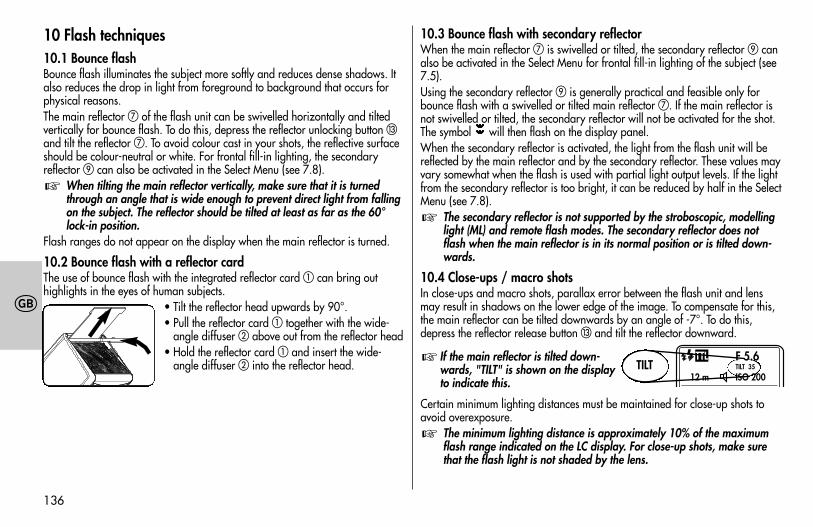
10.2 Bounce flash with a reflector cardThe use of bounce flash with the integrated reflector card can bring out highlights in the eyes of human subjects.
• Tilt the reflector head upwards by 90°.• Pull the reflector card together with the wide-
angle diffuser � above out from the reflector head• Hold the reflector card and insert the wide-
angle diffuser � into the reflector head.
☞
10.3 Bounce flash with secondary reflectorWhen the main reflector is swivelled or tilted, the secondary reflector canalso be activated in the Select Menu for frontal fill-in lighting of the subject (see7.5).Using the secondary reflector is generally practical and feasible only forbounce flash with a swivelled or tilted main reflector . If the main reflector isnot swivelled or tilted, the secondary reflector will not be activated for the shot.The symbol will then flash on the display panel.When the secondary reflector is activated, the light from the flash unit will bereflected by the main reflector and by the secondary reflector. These values mayvary somewhat when the flash is used with partial light output levels. If the lightfrom the secondary reflector is too bright, it can be reduced by half in the SelectMenu (see 7.8).
The secondary reflector is not supported by the stroboscopic, modellinglight (ML) and remote flash modes. The secondary reflector does notflash when the main reflector is in its normal position or is tilted down-wards.
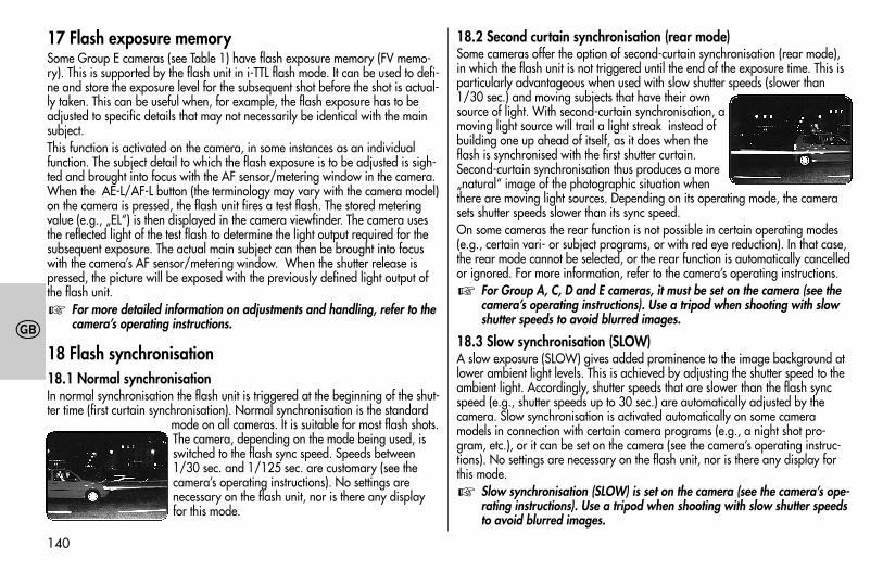
10.4 Close-ups / macro shotsIn close-ups and macro shots, parallax error between the flash unit and lensmay result in shadows on the lower edge of the image. To compensate for this,the main reflector can be tilted downwards by an angle of -7°. To do this,depress the reflector release button � and tilt the reflector downward.
If the main reflector is tilted down-wards, "TILT" is shown on the displayto indicate this.
Certain minimum lighting distances must be maintained for close-up shots toavoid overexposure.
The minimum lighting distance is approximately 10% of the maximumflash range indicated on the LC display. For close-up shots, make surethat the flash light is not shaded by the lens.
☞
☞
☞
F 5.6TILT 35
12 m ISO 200
TTLTILT
709 47 0159.A1 58AF-2 Ni Print 26.07.2010 14:13 Uhr Seite 136
137
�
10.5 Manual flash exposure correctionsThe auto flash exposure mode of the flash unit, as of most cameras, is adjustedto a reflection factor of 25% (the average reflection factor of flash subjects). Adark background that absorbs much of the light or a highly reflective brightbackground (backlit shots, for example) may result in, respectively, underexpo-sure or overexposure of the subject.To offset these effects, the flash exposure can be adjusted manually for the shotwith a correction value. The extent of the correction depends on the contrast bet-ween subject and background.In TTL and automatic flash modes, manual flash exposure correction factors offrom -3 EV (f-stops) to +3 EV (f-stops) can be adjusted on the flash unit in one-third increments.Many cameras have a setting element for exposure corrections that can also beused in TTL flash mode. Please refer to the information in the camera’s operatinginstructions.Dark subject in front of a bright background:Positive correction value (approximately +1 to +2 f-stops EV). Bright subject in front of a dark background:Negative correction value (approximately -1 to -2 f-stops EV).When a correction value is set, the flash range indicated on the flash unitdisplay may change as it adjusts to the correction value (depending on the typeof camera). For adjustments, see 6.4.
Manual flash exposure correction is possible in TTL flash mode only if thecamera supports this function (consult the camera’s operating instructions). If the camera does not support this function, the adjustedcorrection value will have no effect. For some camera models, the manu-al flash exposure corrections must be adjusted on the camera. If this isthe case, no correction value will appear on the flash unit display.
☞
11 Flash readiness indicationWhen the flash capacitor is charged, the flash readi-ness symbol � lights up on the flash unit, indicatingthat the flash is ready to fire. This means that flash lightcan be used for the next shot. Flash readiness is also transmitted to the cameraand indicated accordingly in the camera’s viewfinder (see 15).If a shot is taken before the flash readiness indicator appears in the camera’sviewfinder, then the flash unit will not be triggered and, if the camera hasalready switched to flash sync speed (see 12), the shot may have the wrongexposure.
The multi-zone AF measuring flash � integrated into the flash unit canbe activated by AF cameras only when flash readiness is indicated (see 20).
12 Automatic flash sync speed controlDepending on the camera model and camera mode, the shutter speed is swit-ched to flash sync speed when flash readiness is reached (see the camera’s ope-rating instructions).Shutter speeds cannot be set faster than the flash sync speed, or they are swit-ched automatically to the flash sync speed. Various cameras have a sync speedrange, for example from 1/30 sec. to 1/125 sec (see the camera’s operatinginstructions). The sync speed set by the camera depends on the camera mode,the ambient light, and the focal length of the lens used.Shutter speeds slower than the flash sync speed can be set according to thecamera mode and the selected flash synchronisation (see also the camera’s ope-rating instructions and 18).
If a camera with a between-the-lens shutter (see the camera’s operatinginstructions) or FP high-speed synchronisation (see 18.4) is used, flashsync speed is not controlled automatically. As a result, the flash can beused at all shutter speeds. If you need the full light output of the flashunit, you should not select a shutter speed that is any faster than 1/125sec.
☞
☞
✴
709 47 0159.A1 58AF-2 Ni Print 26.07.2010 14:13 Uhr Seite 137
138
�
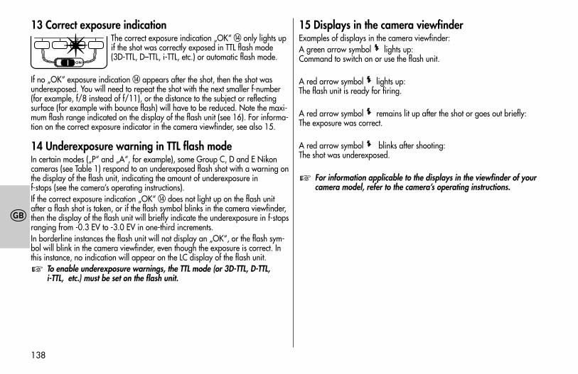
13 Correct exposure indicationThe correct exposure indication „OK“ � only lights upif the shot was correctly exposed in TTL flash mode(3D-TTL, D–TTL, i-TTL, etc.) or automatic flash mode.
If no „OK“ exposure indication � appears after the shot, then the shot wasunderexposed. You will need to repeat the shot with the next smaller f-number(for example, f/8 instead of f/11), or the distance to the subject or reflectingsurface (for example with bounce flash) will have to be reduced. Note the maxi-mum flash range indicated on the display of the flash unit (see 16). For informa-tion on the correct exposure indicator in the camera viewfinder, see also 15.
14 Underexposure warning in TTL flash modeIn certain modes („P“ and „A“, for example), some Group C, D and E Nikoncameras (see Table 1) respond to an underexposed flash shot with a warning onthe display of the flash unit, indicating the amount of underexposure in f-stops (see the camera’s operating instructions).If the correct exposure indication „OK“ � does not light up on the flash unitafter a flash shot is taken, or if the flash symbol blinks in the camera viewfinder,then the display of the flash unit will briefly indicate the underexposure in f-stopsranging from -0.3 EV to -3.0 EV in one-third increments.In borderline instances the flash unit will not display an „OK“, or the flash sym-bol will blink in the camera viewfinder, even though the exposure is correct. Inthis instance, no indication will appear on the LC display of the flash unit.
To enable underexposure warnings, the TTL mode (or 3D-TTL, D-TTL, i-TTL, etc.) must be set on the flash unit.
☞
15 Displays in the camera viewfinderExamples of displays in the camera viewfinder:A green arrow symbol lights up:Command to switch on or use the flash unit.
A red arrow symbol lights up:The flash unit is ready for firing.
A red arrow symbol remains lit up after the shot or goes out briefly:The exposure was correct.
A red arrow symbol blinks after shooting:The shot was underexposed.
For information applicable to the displays in the viewfinder of yourcamera model, refer to the camera’s operating instructions.
☞
✴
709 47 0159.A1 58AF-2 Ni Print 26.07.2010 14:13 Uhr Seite 138
139
�
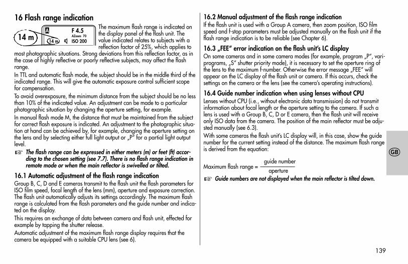
16 Flash range indicationThe maximum flash range is indicated onthe display panel of the flash unit. Thevalue indicated relates to subjects with areflection factor of 25%, which applies to
most photographic situations. Strong deviations from this reflection factor, as inthe case of highly reflective or poorly reflective subjects, may affect the flashrange.In TTL and automatic flash mode, the subject should be in the middle third of theindicated range. This will give the automatic exposure control sufficient scopefor compensation. To avoid overexposure, the minimum distance from the subject should be no lessthan 10% of the indicated value. An adjustment can be made to a particularphotographic situation by changing the aperture setting, for example.In manual flash mode M, the distance that must be maintained from the subjectfor correct flash exposure is indicated. An adjustment to the photographic situa-tion at hand can be achieved by, for example, changing the aperture setting onthe lens and by selecting either full light output or „P“ for a partial light outputlevel.
The flash range can be expressed in either meters (m) or feet (ft) accor-ding to the chosen setting (see 7.7). There is no flash range indication inremote mode or when the main reflector is swivelled or tilted.
16.1 Automatic adjustment of the flash range indicationGroup B, C, D and E cameras transmit to the flash unit the flash parameters forISO film speed, focal length of the lens (mm), aperture and exposure correction.The flash unit automatically adjusts its settings accordingly. The maximum flashrange is calculated from the flash parameters and the guide number and indica-ted on the display.This requires an exchange of data between camera and flash unit, effected forexample by tapping the shutter release.Automatic adjustment of the maximum flash range display requires that thecamera be equipped with a suitable CPU lens (see 6).
☞
16.2 Manual adjustment of the flash range indicationIf the flash unit is used with a Group A camera, then zoom position, ISO filmspeed and f-stop parameters must be adjusted manually on the flash unit if theflash range indication is to be reliable (see Chapter 6).
16.3 „FEE“ error indication on the flash unit’s LC displayOn some cameras and in some camera modes (for example, program „P“, vari-programs, „S“ shutter priority mode), it is necessary to set the aperture ring ofthe lens to the maximum f-number. Otherwise the error message „FEE“ willappear on the LC display of the flash unit or camera. If this occurs, check thesettings on the camera or the lens (see the camera’s operating instructions).
16.4 Guide number indication when using lenses without CPULenses without CPU (i.e., without electronic data transmission) do not transmitinformation about focal length or the aperture setting to the camera. If such alens is used with a Group B, C, D or E camera, then the flash unit will receiveonly ISO data from the camera. The position of the main reflector must be adju-sted manually (see 6.3).With some cameras the flash unit’s LC display will, in this case, show the guidenumber for the current setting instead of the distance. The maximum flash rangeis derived from the equation:
guide numberMaximum flash range = —————————
apertureGuide numbers are not displayed when the main reflector is tilted down.☞
F 4.5AZoom 70
14 m ISO 200
A14 m
709 47 0159.A1 58AF-2 Ni Print 26.07.2010 14:13 Uhr Seite 139
�
17 Flash exposure memorySome Group E cameras (see Table 1) have flash exposure memory (FV memo-ry). This is supported by the flash unit in i-TTL flash mode. It can be used to defi-ne and store the exposure level for the subsequent shot before the shot is actual-ly taken. This can be useful when, for example, the flash exposure has to beadjusted to specific details that may not necessarily be identical with the mainsubject.This function is activated on the camera, in some instances as an individualfunction. The subject detail to which the flash exposure is to be adjusted is sigh-ted and brought into focus with the AF sensor/metering window in the camera.When the AE-L/AF-L button (the terminology may vary with the camera model)on the camera is pressed, the flash unit fires a test flash. The stored meteringvalue (e.g., „EL“) is then displayed in the camera viewfinder. The camera usesthe reflected light of the test flash to determine the light output required for thesubsequent exposure. The actual main subject can then be brought into focuswith the camera’s AF sensor/metering window. When the shutter release ispressed, the picture will be exposed with the previously defined light output ofthe flash unit.
For more detailed information on adjustments and handling, refer to thecamera’s operating instructions.
18 Flash synchronisation18.1 Normal synchronisationIn normal synchronisation the flash unit is triggered at the beginning of the shut-ter time (first curtain synchronisation). Normal synchronisation is the standard
mode on all cameras. It is suitable for most flash shots.The camera, depending on the mode being used, isswitched to the flash sync speed. Speeds between1/30 sec. and 1/125 sec. are customary (see thecamera’s operating instructions). No settings arenecessary on the flash unit, nor is there any displayfor this mode.
☞
18.2 Second curtain synchronisation (rear mode)Some cameras offer the option of second-curtain synchronisation (rear mode),in which the flash unit is not triggered until the end of the exposure time. This isparticularly advantageous when used with slow shutter speeds (slower than1/30 sec.) and moving subjects that have their ownsource of light. With second-curtain synchronisation, amoving light source will trail a light streak instead ofbuilding one up ahead of itself, as it does when theflash is synchronised with the first shutter curtain.Second-curtain synchronisation thus produces a more„natural“ image of the photographic situation whenthere are moving light sources. Depending on its operating mode, the camerasets shutter speeds slower than its sync speed.On some cameras the rear function is not possible in certain operating modes(e.g., certain vari- or subject programs, or with red eye reduction). In that case,the rear mode cannot be selected, or the rear function is automatically cancelledor ignored. For more information, refer to the camera’s operating instructions.
For Group A, C, D and E cameras, it must be set on the camera (see thecamera’s operating instructions). Use a tripod when shooting with slowshutter speeds to avoid blurred images.
18.3 Slow synchronisation (SLOW)A slow exposure (SLOW) gives added prominence to the image background atlower ambient light levels. This is achieved by adjusting the shutter speed to theambient light. Accordingly, shutter speeds that are slower than the flash syncspeed (e.g., shutter speeds up to 30 sec.) are automatically adjusted by thecamera. Slow synchronisation is activated automatically on some cameramodels in connection with certain camera programs (e.g., a night shot pro-gram, etc.), or it can be set on the camera (see the camera’s operating instruc-tions). No settings are necessary on the flash unit, nor is there any display forthis mode.
Slow synchronisation (SLOW) is set on the camera (see the camera’s ope-rating instructions). Use a tripod when shooting with slow shutter speedsto avoid blurred images.
☞
☞
140
709 47 0159.A1 58AF-2 Ni Print 26.07.2010 14:13 Uhr Seite 140
141
�
18.4 Automatic FP high-speed synchronisationVarious Group E cameras (D2Hs and D200, for example) support automatic FPhigh-speed synchronisation (see the camera’s operating instructions). This flashmode makes it possible to use a flash unit even with shutter speeds that arefaster than the flash sync speed. Interesting results may be achieved in this modewhen, for example, a wide open aperture (e.g., f/2.0) is used to limit the depthof field in portrait shots taken in very bright ambient light. The flash unit sup-ports high-speed synchronisation in i-TTL, i-TTL-BL and M flash modes.For physical reasons, however, FP high-speed synchronisation significantly redu-ces the guide number and the maximum flash range. Be sure to note, therefore,the flash range on the LC display of the flash unit. FP high-speed synchronisa-tion is activated automatically if a shutter speed faster than the flash sync speedis set on the camera, whether manually or automatically by the exposure pro-gram.
Note that in the case of FP high-speed synchronisation the guide numberof the flash unit also depends on the shutter speed. The faster the shutterspeed, the lower the guide number.
Automatic FP high-speed synchronisation is set on the camera (see the camera’soperating instructions). „FP“ will then also appear on the flash unit’s displaypanel, for example.
19 Preflash function for red-eye reduction The red-eye effect occurs when the person being photographed is looking moreor less straight into the camera, the ambient lighting is poor, and the flash unit ismounted close to the camera. The flash unit then illuminates the interior of thesubject’s eyes through the pupils.Some camera models have a preflash function for reducing the red-eye effect.One or more preflashes induce the pupils to contract more, thereby reducing thered-eye effect.
On some cameras, the preflash function supports only the camera’s inter-nal flash unit or an illuminator incorporated in the camera body (see thecamer’s operating instructions). The preflash function is set on the camera
☞
☞
(see the camera’s operating instructions). Second curtain synchronisation(REAR) is not possible when the preflash function is used.
20 Multi-zone AF measuring beamThe multi-zone AF measuring beam � is activated in the flash unit by thecamera when the ambient lighting conditions become inadequate for automaticfocusing. It projects onto the subject a striped pattern that the camera can use tofocus. Depending on the camera’s activated AF sensor, the AF beam has a ran-ge of approximately 6 m to 9 m (with a standard 1.7/50 mm lens). The maxi-mum flash range is reached with the camera’s central AF sensor. Parallax errorbetween lens and AF measuring beam limits the close-up range with theAF measuring beam to approximately 0.7 m to 1 m.
If the multi-zone AF measuring beam � is to be activated by the camera,the „single AF (S)“ autofocus mode must be set on the camera and theflash unit must indicate flash readiness. Some camera models supportonly the camera’s internal AF measuring beam. In this case, the multi-zone AF measuring beam � of the flash unit is not activated (as in thecase of compact cameras; see the camera’s operating instructions).
Low-speed zoom lenses can significantly curtail the range of theAF measuring beam. Some cameras support the AF measuring beam in the flash unit only with thecamera’s central AF sensor. If a peripheral AF sensor is selected, then theAF measuring beam will not be activated in the flash unit.
☞
709 47 0159.A1 58AF-2 Ni Print 26.07.2010 14:13 Uhr Seite 141
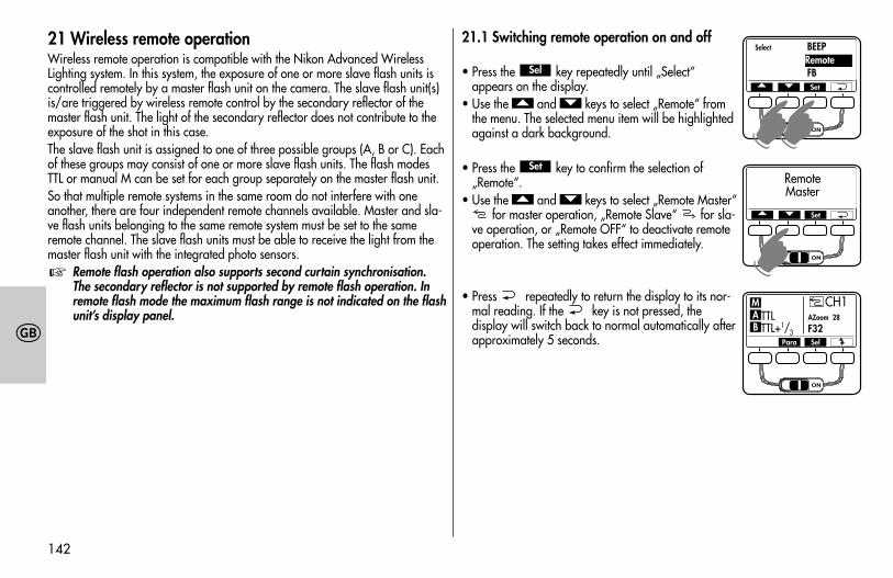
142
�
21 Wireless remote operation Wireless remote operation is compatible with the Nikon Advanced WirelessLighting system. In this system, the exposure of one or more slave flash units iscontrolled remotely by a master flash unit on the camera. The slave flash unit(s)is/are triggered by wireless remote control by the secondary reflector of themaster flash unit. The light of the secondary reflector does not contribute to theexposure of the shot in this case.The slave flash unit is assigned to one of three possible groups (A, B or C). Eachof these groups may consist of one or more slave flash units. The flash modesTTL or manual M can be set for each group separately on the master flash unit.So that multiple remote systems in the same room do not interfere with oneanother, there are four independent remote channels available. Master and sla-ve flash units belonging to the same remote system must be set to the sameremote channel. The slave flash units must be able to receive the light from themaster flash unit with the integrated photo sensors.
Remote flash operation also supports second curtain synchronisation.The secondary reflector is not supported by remote flash operation. Inremote flash mode the maximum flash range is not indicated on the flashunit’s display panel.
☞
21.1 Switching remote operation on and off
• Press the key repeatedly until „Select“ appears on the display.
• Use the and keys to select „Remote“ fromthe menu. The selected menu item will be highlightedagainst a dark background.
• Press the key to confirm the selection of„Remote“.
• Use the and keys to select „Remote Master“for master operation, „Remote Slave“ for sla-
ve operation, or „Remote OFF“ to deactivate remoteoperation. The setting takes effect immediately.
• Press repeatedly to return the display to its nor-mal reading. If the key is not pressed, thedisplay will switch back to normal automatically afterapproximately 5 seconds.
��
Set
��
Sel
Para Sel
CH1TTL AZoom 28
TTL+1/3 F32BAM
Select BEEP
FBRemote
� � Set
☛☛
RemoteMaster
� � Set
☛
709 47 0159.A1 58AF-2 Ni Print 26.07.2010 14:13 Uhr Seite 142
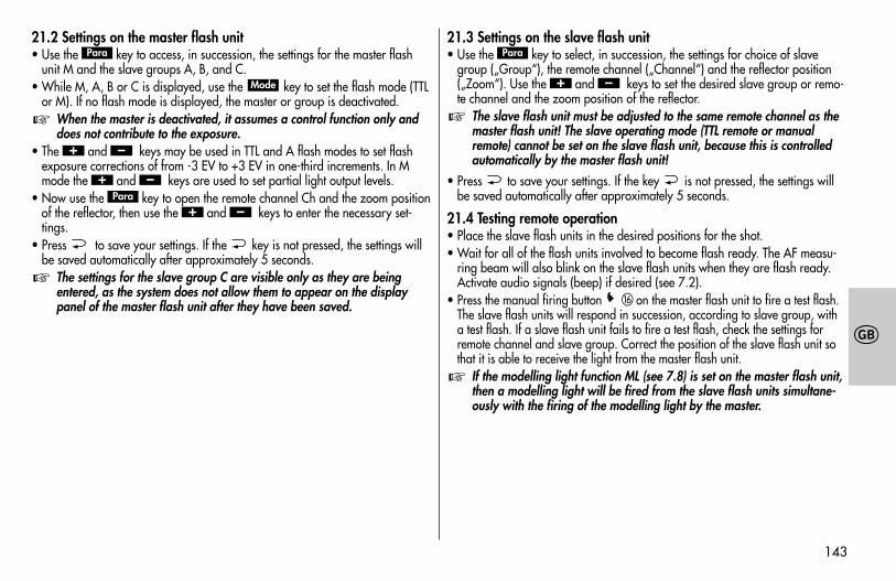
143
�
21.2 Settings on the master flash unit• Use the key to access, in succession, the settings for the master flash
unit M and the slave groups A, B, and C.• While M, A, B or C is displayed, use the key to set the flash mode (TTL
or M). If no flash mode is displayed, the master or group is deactivated.When the master is deactivated, it assumes a control function only anddoes not contribute to the exposure.
• The and keys may be used in TTL and A flash modes to set flashexposure corrections of from -3 EV to +3 EV in one-third increments. In Mmode the and keys are used to set partial light output levels.
• Now use the key to open the remote channel Ch and the zoom positionof the reflector, then use the and keys to enter the necessary set-tings.
• Press to save your settings. If the key is not pressed, the settings willbe saved automatically after approximately 5 seconds.
The settings for the slave group C are visible only as they are beingentered, as the system does not allow them to appear on the displaypanel of the master flash unit after they have been saved.
☞
–+Para
–+
–+
☞
Mode
Para21.3 Settings on the slave flash unit• Use the key to select, in succession, the settings for choice of slave
group („Group“), the remote channel („Channel“) and the reflector position(„Zoom“). Use the and keys to set the desired slave group or remo-te channel and the zoom position of the reflector.
The slave flash unit must be adjusted to the same remote channel as themaster flash unit! The slave operating mode (TTL remote or manualremote) cannot be set on the slave flash unit, because this is controlledautomatically by the master flash unit!
• Press to save your settings. If the key is not pressed, the settings willbe saved automatically after approximately 5 seconds.
21.4 Testing remote operation• Place the slave flash units in the desired positions for the shot.• Wait for all of the flash units involved to become flash ready. The AF measu-
ring beam will also blink on the slave flash units when they are flash ready.Activate audio signals (beep) if desired (see 7.2).
• Press the manual firing button � on the master flash unit to fire a test flash.The slave flash units will respond in succession, according to slave group, witha test flash. If a slave flash unit fails to fire a test flash, check the settings forremote channel and slave group. Correct the position of the slave flash unit sothat it is able to receive the light from the master flash unit.
If the modelling light function ML (see 7.8) is set on the master flash unit,then a modelling light will be fired from the slave flash units simultane-ously with the firing of the modelling light by the master.
☞
☞
–+
Para
709 47 0159.A1 58AF-2 Ni Print 26.07.2010 14:13 Uhr Seite 143
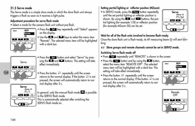
144
�
21.5 Servo modeThe Servo mode is a simple slave mode in which the slave flash unit always triggers a flash as soon as it receives a light pulse.
Adjustment procedure for servo flash mode• Select a mode for the camera flash unit without pre-flash.
• Press the key repeatedly until "Select" appearson the display.
• Use the and keys to select the menu item"Remote". The selected menu item will be highlightedwith a dark bar.
• Press the button and select “Servo” by pres-sing the and buttons. The setting will takeeffect immediately.
• Press the button repeatedly until the screenreturns to the normal display. If the button is notpressed, the screen will automatically return to nor-mal display after 5 s.
In general, only the manual flash mode is possiblein the SERVO flash mode. This is automatically selected after switching the SERVO flash mode on.
M
��Set
��
Sel
Setting partial lighting or reflector position (MZoom)• In SERVO mode, press the button repeatedly
until the set partial lighting or reflector position isshown. By using the and buttons, the par-tial lighting (for example 1/8) or reflector position(for example MZoom 50) can be set.
Wait for all of the flash units involved to become flash-ready.Once the slave flash unit is flash-ready, its AF measuring beam � will start blin-king.
Slave groups and remote channels cannot be set in SERVO mode.
Switching Servo flash mode off• Press repeatedly until “REMOTE” is shown in the screen• Press the button and by using the button,
select the menu item “REMOTE OFF”. The selectedmenu item will be highlighted with a dark bar. Thesetting will take effect immediately.
• Press the button repeatedly until the screenreturns to the normal display. If the button is notpressed, the screen will automatically return to nor-mal display after 5 s.
�Set
Sel
☞
–+
Para
Para Sel
ServoMZoom 35
P1/64
Select BEEP
FBRemote
� � Set
☛☛
RemoteOFF
� � Set
☛
Para Sel
ServoMZoom 35
P1/1
Select BEEP
FBRemote
� � Set
☛☛
Servo� � Set
☛☛
709 47 0159.A1 58AF-2 Ni Print 26.07.2010 14:13 Uhr Seite 144
145
�
22 Care and maintenanceRemove dust and grime with a soft dry cloth or silicon-treated cloth. Do not usecleaning agents as these may damage the plastic parts.
22.1 Firmware updatesThe flash unit’s firmware can be updated through the USB port � and adjustedto the technical requirements of future cameras (Firmware Update).For more information, visit the Metz homepage at www.metz.de.
22.2 ResetThe flash unit can be reset to the factory settings. To do this, press the key and hold it down for approx. 3 seconds. „Reset“ will then appear on thedisplay panel. After about 3 seconds the display reading will return to the facto-ry setting.
This will not affect the firmware updates for the flash unit.
22.3 Flash capacitor formingThe flash capacitor built into the flash unit undergoes physical change if the unitis not switched on for a prolonged period. For this reason it is necessary toswitch the unit on for approximately 10 minutes at least once every threemonths. The power supplied by the power source must be sufficient to cause theflash readiness indicator to light up no more than one minute after the flash unitis switched on.
☞
Mode
23 TroubleshootingShould the flash unit fail to function properly or meaningless contentappear on the flash unit display panel, switch the flash unit off with themain switch � for approximately 10 seconds. Check the camera settingsand make sure the foot of the flash unit is mounted correctly in thecamera’s accessory shoe.
Replace the batteries with new or freshly charged batteries.The flash unit should function normally again once it is switched back on. If thisis not the case, contact your local dealer.Below is a list of some of the problems that may occur when the flash unit isused. For each item, possible causes and remedies for the problem are listed.No maximum flash range indication appears on the display panel.• The main reflector is not in normal position.• The flash unit has been set to remote operation."TILT" appears on the display• The main reflector is tilted downwards for close-up or macro shots."POWERPACK" appears on the display• An unauthorised power pack has been connected to the mecablitz. Use only a
Metz Power Pack P76.• A Metz Power Pack P76 is connected and there are still batteries in the bat-
tery compartment of the mecablitz. Remove the batteries from the mecablitz.A battery warning appears on the display • When the battery warning appears on the display there is still enough power
left for a few more flashes. See also chapter 3.2 "Replacing batteries". Thereare, however, battery batches with which the battery warning appears relati-vely early, even though there may still be up to 50 % of the flashes still availa-ble. In wireless remote mode it is not possible to provide a battery warning forsystem-related reasons.
☞
709 47 0159.A1 58AF-2 Ni Print 26.07.2010 14:13 Uhr Seite 145
146
�
A battery symbol appears on the display • There is a Metz Power Pack P76 connected to the mecablitz and there are
batteries in the battery compartment of the mecablitz. Remove batteries fromthe mecablitz.
The AF measuring beam of the flash unit is not activated.• The flash unit is not ready for firing.• The camera is not in Single AF mode (S-AF).• The camera supports only its own internal AF measuring beam.• Some cameras support the AF measuring beam in the flash unit only with the
camera’s central AF sensor. If a peripheral AF sensor is selected, then the AFmeasuring beam will not be activated in the flash unit. Activate the central AFsensor.
The reflector position is not automatically adjusted to the current zoom posi-tion of the lens.• The camera is not transmitting any digital data to the flash unit (Group A
cameras).• There is no exchange of data between the flash unit and the camera. Tap the
camera’s shutter release.• The camera is equipped with a lens without CPU.• The main reflector is swivelled out of its locked normal position.• The wide-angle diffuser folds out from the main reflector.• A Mecabounce is mounted in front of the main reflector.The aperture setting on the flash unit is not automatically adjusted to that ofthe lens.• The camera is not transmitting any digital data to the flash unit (Group A
cameras).• There is no exchange of data between the flash unit and the camera. Tap the
camera’s shutter release.• The camera is equipped with a lens without CPU.
The secondary reflector cannot be activated, or no flash is triggered.• The secondary reflector does not support the stroboscopic, remote and model-
ling light (ML) flash modes. In these modes the secondary reflector cannot beactivated, or the secondary reflector does not trigger a flash.
• The main reflector is in its normal position or tilted downwards. The secondary reflector flashes even though it is switched off.• The mecablitz operates as a master in the remote system. The secondary
reflector of the master flash unit controls the slave flash units. The light of thesecondary reflector does not contribute to the exposure of the shot in thiscase.
The TTL fill-in flash BL cannot be set.• There has been no exchange of data between the flash unit and the camera.
Tap the camera’s shutter release.• The camera does not support TTL fill-in flash mode.• The camera is switched to spot metering. Choose another metering type, for
example multi-zone metering.The setting for manual TTL flash exposure correction has no effect.• The camera does not support manual TTL flash exposure correction on the
flash unit (Group A cameras, for example).Flash unit cannot be set for wireless remote operation as the master flash unit.• Wireless remote operation is supported only by Group E cameras. Remote
flash operation is not available with other cameras.• There has been no exchange of data between the flash unit and the camera.
Tap the camera’s shutter release.
TTL
709 47 0159.A1 58AF-2 Ni Print 26.07.2010 14:13 Uhr Seite 146
147
�
Automatic switching to the flash sync speed fails to occur.• The camera has a between-the-lens shutter (as do most compact cameras),
Switching to sync speed is therefore unnecessary.• The camera operates with FP high-speed synchronisation (camera setting). In
this case no switching to sync speed occurs.• The camera operates with shutter speeds that are slower than the flash sync
speed. Depending on the camera mode, there is no switch to flash sync speed(see the camera’s operating instructions).
The shots have shadows in the bottom of the image.• Because of parallax error between lens and flash unit, close-up shots may not,
depending on the focal length at the bottom of the image, be fully illuminated.Tilt the main reflector downwards or turn the wide-angle diffuser in front ofthe reflector.
The shots are too dark.• The subject is beyond the range of the flash unit. Note: Using bounce flash
reduces the range of the flash unit. • The subject contains very bright or highly reflective areas. The metering
system of the camera or flash unit is deceived as a result. Set a positive manu-al flash exposure correction, e.g., +1 EV.
The shots are too bright.• For close-ups it is necessary to ensure that certain minimum lighting distances
are maintained to avoid overexposure. The minimum distance from the sub-ject should be at least 10% of the maximum flash range indicated on thedisplay.
The flash parameters for ISO film speed and the aperture (f-stop) cannot beadjusted on the flash unit.• There is an exchange of digital data between flash unit and camera through
which the ISO and aperture (f) values are automatically adjusted on the flashunit. ISO and aperture are adjustable only when no digital data exchange istaking place, as for example with Group A cameras.
709 47 0159.A1 58AF-2 Ni Print 26.07.2010 14:13 Uhr Seite 147
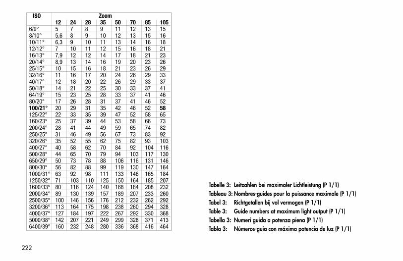
222
Tabelle 3: Leitzahlen bei maximaler Lichtleistung (P 1/1)Tableau 3: Nombres-guides pour la puissance maximale (P 1/1)Tabel 3: Richtgetallen bij vol vermogen (P 1/1)Table 3: Guide numbers at maximum light output (P 1/1)Tabella 3: Numeri guida a potenza piena (P 1/1)Tabla 3: Números-guía con máxima potencia de luz (P 1/1)
709 47 0159.A1 58AF-2 Ni Print 26.07.2010 14:13 Uhr Seite 222
ISO Zoom12 24 28 35 50 70 85 105
6/9° 5 7 8 9 11 12 13 158/10° 5,6 8 9 10 12 13 15 1610/11° 6,3 9 10 11 13 14 16 1812/12° 7 10 11 12 15 16 18 2116/13° 7,9 12 12 14 17 18 21 2320/14° 8,9 13 14 16 19 20 23 2625/15° 10 15 16 18 21 23 26 2932/16° 11 16 17 20 24 26 29 3340/17° 12 18 20 22 26 29 33 3750/18° 14 21 22 25 30 33 37 4164/19° 15 23 25 28 33 37 41 4680/20° 17 26 28 31 37 41 46 52100/21° 20 29 31 35 42 46 52 58125/22° 22 33 35 39 47 52 58 65160/23° 25 37 39 44 53 58 66 73200/24° 28 41 44 49 59 65 74 82250/25° 31 46 49 56 67 73 83 92320/26° 35 52 55 62 75 82 93 103400/27° 40 58 62 70 84 92 104 116500/28° 44 65 70 79 94 103 117 130650/29° 50 73 78 88 106 116 131 146800/30° 56 82 88 99 119 130 147 1641000/31° 63 92 98 111 133 146 165 1841250/32° 71 103 110 125 150 164 185 2071600/33° 80 116 124 140 168 184 208 2322000/34° 89 130 139 157 189 207 233 2602500/35° 100 146 156 176 212 232 262 2923200/36° 113 164 175 198 238 260 294 3284000/37° 127 184 197 222 267 292 330 3685000/38° 142 207 221 249 299 328 371 4136400/39° 160 232 248 280 336 368 416 464
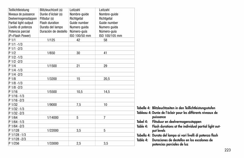
223
Tabelle 4: Blitzleuchtzeiten in den TeillichtleistungsstufenTableau 4: Durée de l’éclair pour les différents niveaux de
puissanceTabel 4: Flitsduur en deelvermogensstappenTable 4: Flash durations at the individual partial light out-
put levelsTabella 4: Durata del lampo ai vari livelli di potenza flashTabla 4: Duraciones de destellos en los escalones de
potencias parciales de luz
Teillichtleistung Blitzleuchtzeit (s) Leitzahl LeitzahlNiveaux de puissance Durée d’éclair (s) Nombre-guide Nombre-guideDeelvermogensstappen Flitsdur (s) Richtgetal RichtgetalPartial light output Flash duration Guide number Guide numberLivello di potenza Durata del lampo Numero guida Numero guidaPotencia parcial Duración de destello Número-guía Número-guía(P=Flash Power) ISO 100/50 mm ISO 100/105 mmP 1/1 1/125 42 58P 1/1 -1/3P 1/1 -2/3P 1/2 1/650 30 41P 1/2 -1/3P 1/2 -2/3P 1/4 1/1500 21 29P 1/4 -1/3P 1/4 -2/3P 1/8 1/3200 15 20,5P 1/8 -1/3P 1/8 -2/3P 1/16 1/5500 10,5 14,5P 1/16 -1/3P 1/16 -2/3P 1/32 1/9000 7,5 10P 1/32 -1/3P 1/32 -2/3P 1/64 1/14000 5 7P 1/64 -1/3P 1/64 -2/3P 1/128 1/22000 3,5 5P 1/128 -1/3P 1/128 -2/3P 1/256 1/33000 2,5 3,5
709 47 0159.A1 58AF-2 Ni Print 26.07.2010 14:13 Uhr Seite 223
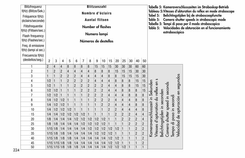
224
Tabelle 5: Kameraverschlusszeiten im Stroboskop-BetriebTableau 5:Vitesses d’obturation du reflex en mode stroboscopeTabel 5: Belichtingstijden bij de stroboscoopfunctieTable 5: Camera shutter speeds in stroboscopic modeTabella 5: Tempi di posa per il modo stroboscopicoTabla 5: Velocidades de obturación en el funcionamiento
estroboscópico
1 2 4 4 8 8 8 8 15 15 15 30 30 30 60 602 1 2 2 4 4 4 4 8 8 8 15 15 15 30 303 1 1 2 2 2 4 4 4 4 8 8 15 15 15 304 1/2 1 1 2 2 2 2 4 4 4 8 8 8 15 155 1/2 1 1 1 2 2 2 2 2 4 4 8 8 15 156 1/2 1/2 1 1 1 2 2 2 2 4 4 8 8 8 157 1/2 1/2 1 1 1 1 2 2 2 4 4 4 8 8 88 1/4 1/2 1/2 1 1 1 1 2 2 2 4 4 4 8 89 1/4 1/2 1/2 1 1 1 1 1 2 2 4 4 4 8 810 1/4 1/2 1/2 1/2 1 1 1 1 1 2 2 4 4 4 815 1/4 1/4 1/2 1/2 1/2 1/2 1 1 1 1 2 2 2 4 420 1/8 1/4 1/4 1/4 1/2 1/2 1/2 1/2 1/2 1 1 2 2 2 425 1/8 1/8 1/4 1/4 1/4 1/2 1/2 1/2 1/2 1 1 1 2 2 230 1/15 1/8 1/4 1/4 1/4 1/4 1/2 1/2 1/2 1/2 1/2 1 1 2 235 1/15 1/8 1/8 1/4 1/4 1/4 1/4 1/2 1/2 1/2 1 1 1 2 240 1/15 1/8 1/8 1/8 1/4 1/4 1/4 1/4 1/4 1/2 1/2 1 1 1 245 1/15 1/15 1/8 1/8 1/4 1/4 1/4 1/4 1/4 1/2 1/2 1 1 1 250 1/15 1/15 1/8 1/8 1/8 1/4 1/4 1/4 1/4 1/2 1/2 1/2 1 1 1
Blitzfrequenzf(Hz) (Blitze/Sek.)
Fréquence f(Hz)(éclairs/seconde)
Flitsfrequentief(Hz) (Flitsen/sec.)
Flash frequencyf(Hz) (Flashes/sec.)
Freq. di emissionef(Hz) (lampi al sec.)
Frecuencia f(Hz)(destellos/seg.)
Bl i tzanzahl
Nombre d’éclairs
Aantal f l i tsen
Number of flashes
Numero lampi
Números de destellos
2 3 4 5 6 7 8 9 10 15 20 25 30 40 50
Kam
erav
ersc
hlus
szei
t in
Seku
nden
Vite
sses
d’o
ptur
atio
n du
ref
lex
en s
Belic
htin
gstij
den
in s
econ
den
Cam
era
shut
ter
spee
d in
sec
onds
Tem
po d
i pos
a in
sec
ondi
Velo
cida
d de
opt
urac
ión
en s
egun
dos
709 47 0159.A1 58AF-2 Ni Print 26.07.2010 14:13 Uhr Seite 224
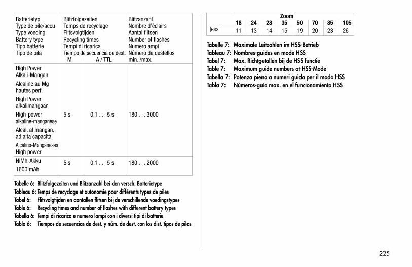
225
Batterietyp Blitzfolgezeiten BlitzanzahlType de pile/accu Temps de recyclage Nombre d’éclairsType voeding Flitsvolgtijden Aantal flitsenBattery type Recycling times Number of flashesTipo batterie Tempi di ricarica Numero ampiTipo de pila Tiempo de secuencia de dest. Número de destellos
M A / TTL min. /max.High PowerAlkali-ManganAlcaline au Mghautes perf.High PoweralkalimangaanHigh-power 5 s 0,1 . . . 5 s 180 . . . 3000alkaline-manganeseAlcal. al mangan.ad alta capacitàAlcalino-ManganesasHigh powerNiMh-Akku 5 s 0,1 . . . 5 s 180 . . . 20001600 mAh0
Tabelle 6: Blitzfolgezeiten und Blitzanzahl bei den versch. BatterietypeTableau 6: Temps de recyclage et autonomie pour différents types de pilesTabel 6: Flitsvolgtijden en aantallen flitsen bij de verschillende voedingstypesTable 6: Recycling times and number of flashes with different battery typesTabella 6: Tempi di ricarica e numero lampi con i diversi tipi di batterieTabla 6: Tiempos de secuencias de dest. y núm. de dest. con los dist. tipos de pilas
Zoom18 24 28 35 50 70 85 10511 13 14 15 19 20 23 26
Tabelle 7: Maximale Leitzahlen im HSS-BetriebTableau 7: Nombres-guides en mode HSSTabel 7: Max. Richtgetallen bij de HSS functieTable 7: Maximum guide numbers at HSS-ModeTabella 7: Potenza piena a numeri guida per il modo HSSTabla 7: Números-guía max. en el funcionamiento HSS
709 47 0159.A1 58AF-2 Ni Print 26.07.2010 14:13 Uhr Seite 225
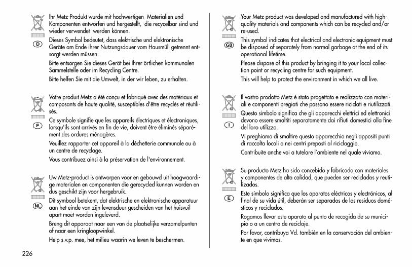
226
Ihr Metz-Produkt wurde mit hochwertigen Materialien undKomponenten entworfen und hergestellt, die recycelbar sind undwieder verwendet werden können.Dieses Symbol bedeutet, dass elektrische und elektronischeGeräte am Ende ihrer Nutzungsdauer vom Hausmüll getrennt ent-sorgt werden müssen.Bitte entsorgen Sie dieses Gerät bei Ihrer örtlichen kommunalenSammelstelle oder im Recycling Centre.Bitte helfen Sie mit die Umwelt, in der wir leben, zu erhalten.
Votre produit Metz a été conçu et fabriqué avec des matériaux etcomposants de haute qualité, susceptibles d'être recyclés et réutili-sés.Ce symbole signifie que les appareils électriques et électroniques,lorsqu'ils sont arrivés en fin de vie, doivent être éliminés séparé-ment des ordures ménagères.Veuillez rapporter cet appareil à la déchetterie communale ou àun centre de recyclage.Vous contribuez ainsi à la préservation de l'environnement.
Uw Metz-product is ontworpen voor en gebouwd uit hoogwaardi-ge materialen en componenten die gerecycled kunnen worden endus geschikt zijn voor hergebruik. Dit symbool betekent, dat elektrische en elektronische apparatuuraan het einde van zijn levensduur gescheiden van het huisvuilapart moet worden ingeleverd. Breng dit apparaat naar een van de plaatselijke verzamelpuntenof naar een kringloopwinkel.Help s.v.p. mee, het milieu waarin we leven te beschermen.
Your Metz product was developed and manufactured with high-quality materials and components which can be recycled and/orre-used.This symbol indicates that electrical and electronic equipment mustbe disposed of separately from normal garbage at the end of itsoperational lifetime.Please dispose of this product by bringing it to your local collec-tion point or recycling centre for such equipment.This will help to protect the environment in which we all live.
Il vostro prodotto Metz è stato progettato e realizzato con materi-ali e componenti pregiati che possono essere riciclati e riutilizzati.Questo simbolo significa che gli apparecchi elettrici ed elettronicidevono essere smaltiti separatamente dai rifiuti domestici alla finedel loro utilizzo.Vi preghiamo di smaltire questo apparecchio negli appositi puntidi raccolta locali o nei centri preposti al riciclaggio.Contribuite anche voi a tutelare l’ambiente nel quale viviamo.
Su producto Metz ha sido concebido y fabricado con materialesy componentes de alta calidad, que pueden ser reciclados y reuti-lizados.Este símbolo significa que los aparatos eléctricos y electrónicos, alfinal de su vida útil, deberán ser separados de los residuos domé-sticos y reciclados.Rogamos llevar este aparato al punto de recogida de su munici-pio o a un centro de reciclaje.Por favor, contribuya Vd. también en la conservación del ambien-te en que vivimos.
�
�
�
�
�
�
709 47 0159.A1 58AF-2 Ni Print 26.07.2010 14:13 Uhr Seite 226
227
Hinweis:
Im Rahmen des CE-Zeichens wurde beider EMV-Prüfung die korrekteBelichtung ausgewertet.
SCA-Kontakte nicht berühren !
In Ausnahmefällen kann eine Berüh-rung zur Beschädigung des Gerätesführen.
�
Remarque:L’exposition correcte a été évaluéelors des essais de CEM dans lecadre de la certification CE.
Ne pas toucher les contacts duSCA !
Il paut arriver que le contact avecles doigts provoque la dégradationde l’appareil.
�
Opmerking:In het kader de CE-markering werdbij de EMV-test de correcte be-lich-ting bepaald.
SCA Contacten niet aanraken !
In uitzonderlijke gevallen kan aanra-ken leiden.
�
Note:Within the framework of the CE ap-proval symbol, correct exposure wasevaluated in the course of the electro-magnetic compatibility test.
Do not touch the SCA contacts !
In exceptional cases the unit can bedamaged if these contacts are touched.
�
Avvertenza:Nell’ambito delle prove EMV per ilsegno CE è stata valutata la correttaesposizione.
Non toccate mai i contatti SCA !
In casi eccezionali il toccare puòcausare danni all’apparecchio.
�
Atención:El símbolo CE significa una valora-ción da exposición correcta con laprueba EMV (prueba de toleranciaelectromagnética).
No tocar los contactos SCA !
En algunos casos un contacto pue-de producir daños en el aparato.
�
Technische Änderungen und Irrtümer vorbehalten !Sous réserve de modifications et d’erreus !Onder voorbehoudvan wijzigingen en vergissingen !Errors excepted. Subject to changes !Riserva di modifiche e disponibilità di fornitura.Con reserva de modificaciones y posibilidades de entrega.
709 47 0159.A1 58AF-2 Ni Print 26.07.2010 14:13 Uhr Seite 227
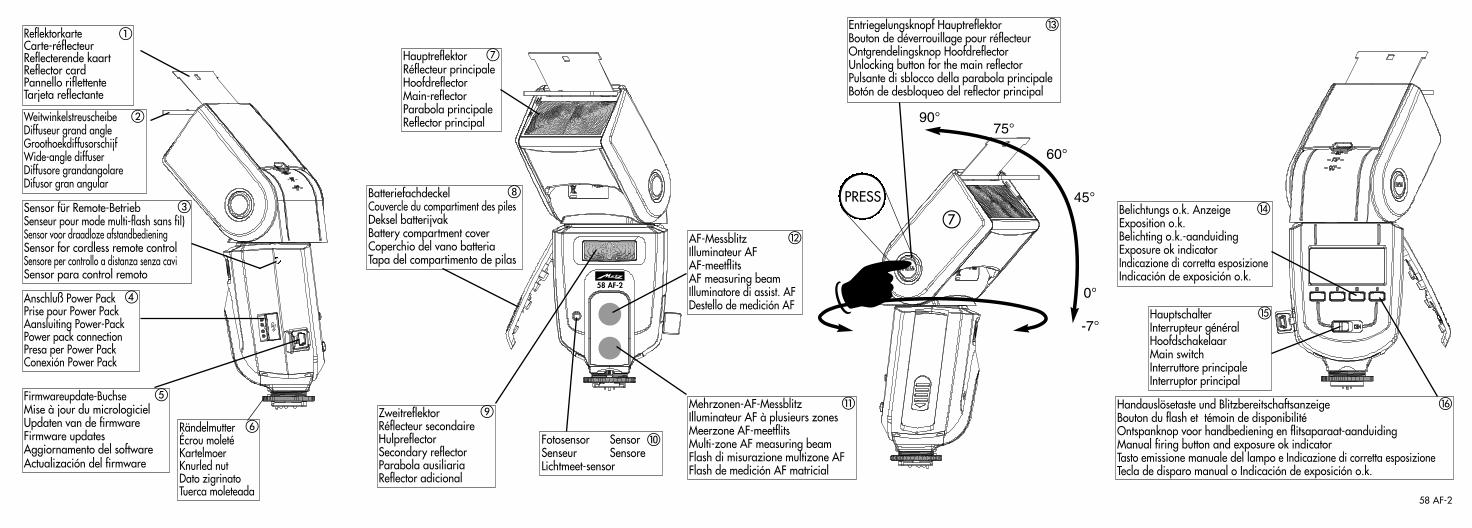
Anschluß Power PackPrise pour Power PackAansluiting Power-PackPower pack connectionPresa per Power PackConexión Power Pack
Firmwareupdate-BuchseMise à jour du micrologicielUpdaten van de firmwareFirmware updatesAggiornamento del softwareActualización del firmware
BatteriefachdeckelCouvercle du compartiment des pilesDeksel batterijvakBattery compartment coverCoperchio del vano batteriaTapa del compartimento de pilas
ReflektorkarteCarte-réflecteurReflecterende kaart Reflector cardPannello riflettenteTarjeta reflectante
WeitwinkelstreuscheibeDiffuseur grand angleGroothoekdiffusorschijfWide-angle diffuserDiffusore grandangolareDifusor gran angular
�
�
�
�
RändelmutterÉcrou moletéKartelmoerKnurled nutDato zigrinatoTuerca moleteada
�
�Fotosensor SensorSenseur SensoreLichtmeet-sensor
�
HauptreflektorRéflecteur principaleHoofdreflectorMain-reflectorParabola principaleReflector principal
Zweitreflektor Réflecteur secondaireHulpreflectorSecondary reflectorParabola ausiliariaReflector adicional
�
HauptschalterInterrupteur généralHoofdschakelaarMain switchInterruttore principaleInterruptor principal
�
AF-MessblitzIlluminateur AFAF-meetflitsAF measuring beamIlluminatore di assist. AFDestello de medición AF
Mehrzonen-AF-MessblitzIlluminateur AF à plusieurs zonesMeerzone AF-meetflitsMulti-zone AF measuring beamFlash di misurazione multizone AFFlash de medición AF matricial
�
Belichtungs o.k. AnzeigeExposition o.k.Belichting o.k.-aanduidingExposure ok indicatorIndicazione di corretta esposizioneIndicación de exposición o.k.
�
Handauslösetaste und BlitzbereitschaftsanzeigeBouton du flash et témoin de disponibilitéOntspanknop voor handbediening en flitsaparaat-aanduidingManual firing button and exposure ok indicatorTasto emissione manuale del lampo e Indicazione di corretta esposizioneTecla de disparo manual o Indicación de exposición o.k.
�
Sensor für Remote-BetriebSenseur pour mode multi-flash sans fil)Sensor voor draadloze afstandbedieningSensor for cordless remote controlSensore per controllo a distanza senza caviSensor para control remoto
58 AF-2
58 AF-2
☛
-7°
0°
45°
60°
75°90°
PRESS
Entriegelungsknopf HauptreflektorBouton de déverrouillage pour réflecteurOntgrendelingsknop HoofdreflectorUnlocking button for the main reflectorPulsante di sblocco della parabola principaleBotón de desbloqueo del reflector principal
�
58 AF-2 - Klappseite 27.07.2010 11:36 Uhr Seite 1
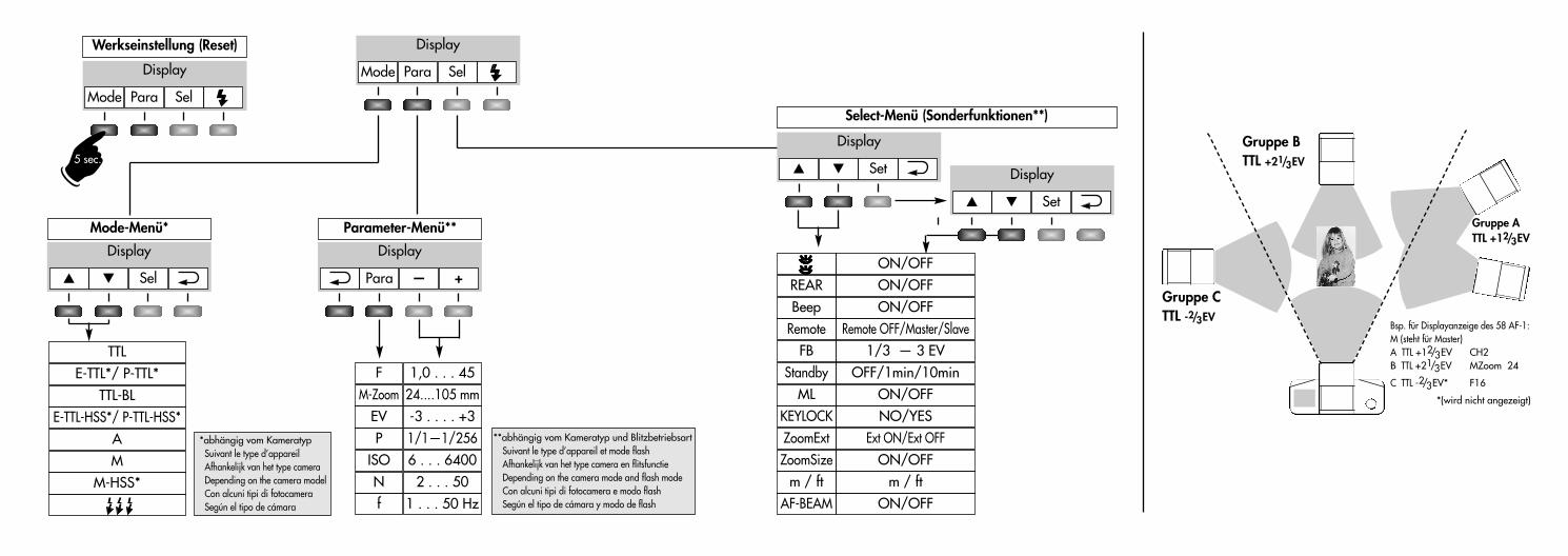
Display
Display
Mode Para Sel
� � Sel
TTLE-TTL*/ P-TTL*
TTL-BLE-TTL-HSS*/ P-TTL-HSS*
AM
M-HSS*
Mode-Menü* Parameter-Menü**
Select-Menü (Sonderfunktionen**)
Werkseinstellung (Reset)
Display
Mode Para Sel
Display
+Para —
FM-Zoom
EV
ISO
1,0 . . . 4524....105 mm-3 . . . . +3
6 . . . 6400P 1/1—1/256
N 2 . . . 50f 1 . . . 50 Hz
Beep
FB
ZoomExtZoomSize
ON/OFFREAR ON/OFF
1/3 — 3 EV
Ext ON/Ext OFFON/OFF
Remote Remote OFF/Master/Slave
m / ft m / ftAF-BEAM ON/OFF
ON/OFF
ML ON/OFFStandby OFF/1min/10min
KEYLOCK NO/YES
Display
� � Set Display
� � Set
*abhängig vom KameratypSuivant le type d’appareilAfhankelijk van het type cameraDepending on the camera modelCon alcuni tipi di fotocameraSegún el tipo de cámara
**abhängig vom Kameratyp und BlitzbetriebsartSuivant le type d’appareil et mode flashAfhankelijk van het type camera en flitsfunctieDepending on the camera mode and flash modeCon alcuni tipi di fotocamera e modo flashSegún el tipo de cámara y modo de flash
☛
5 sec.
Gruppe ATTL +12/3 EV
Gruppe BTTL +21/3 EV
Gruppe CTTL -2/3 EV
Bsp. für Displayanzeige des 58 AF-1:M (steht für Master)A TTL +12/3 EV CH2B TTL +21/3 EV MZoom 24
C TTL -2/3 EV* F16
*(wird nicht angezeigt)
58 AF-2 - Klappseite 27.07.2010 11:36 Uhr Seite 2
709 47 0159.A1
� � � � � �
709 47 0159.A1 58AF-2 Ni Print 26.07.2010 14:13 Uhr Seite 228
This document was archived December 2013 forphotomacrography documentation purposes at thehttp://extreme-macro.co.uk extreme macro website.All rights reserved by the document authors