mech 3-2010 02 - agh university of science and...
TRANSCRIPT

102
������ ���� �� ��� ����
�������� ������� ���� ������������ �������� ������ ���������
! �"#���$"%���&��"'(�%�'�)��%*�%""��%*�����'�+�%�+"�,��-��&��"'(%�)�*-��.��/� ����)�%�0�#�1��2$"'( #/ "�1 #)
��������� ��� �������3�) � 45� �� � 6� 4787
��������!���� �������
!
�������� ������� ���� ������������ �������� ��������������� ������ ��������� ��� ����� ���� 3�3�
�������
��� ����� �������� �� ��� � ������ ����� ��� ������ ��� ���� �� �� � ������ ������� � �� �� ���� ���� ���
���!� "� �#� ��� � ��� ��� ���� ��� �� ����� ���$� � �� �%����� �� ������ ����� ��� �� ��� � ���� �� ���#���
����� ������ ��#�� �� ������ ��� �� ���� ����!� ���������$�� ���� �$����� ��� ���� � �� ����#� ������� ���� ���� ����#���
��� ��� �� �$����� ����#���� ������ ��$� ����� �� ���� � ����� �� � ���� �!� �������� � �� �� ������ ���� �� � ����
��� ������ � � �����#� ��� ���#� � ������� �� �� � �� �� ���� �����$!� &�� ��� ��� ���� �� ���� ���� ������
�� ����� �� � � �����#� ��� ���#� �� ������ �!�!� �� ����� �� ����� ������ �� ������ �����#� ��� ���#� �
���� �� ����� ����� ��� ����� ���� ��%����� �� ������ �� ���� ��� ����� ������ ��������� ������!� '�� ��� � �� ����� �
������� �� ��� � ����� ������ � � ���� ���#� ������� �� ���#� �� ����� �� �� �#� ��� � ��� ��� ���� ��
������ �� ���� ��� � ����!� &� ����� ���� � ��� ������� �� ����� ������� ��� ���!� (����� � ������ �� ����� �� �����#
��� ���#� � ������� ����� ��� �� ���� ��� ��� ���� ��� ����� �����#� ��� ���#� �� ����� � ������� ��� ��#
�� ����)� ��� ���� � �#������� *��������� ��#��� �+ � "����������� ,-.� /*�"0!
�������1� ��� ���� �� ������� ������ ���� ��� ����� � ���� �� ���������
�'*2"�� 3��'���43�� "2� 5�43��4�3&�� "26��4�4�73')2� 6�4'(&')�� *'�6'��*���� �4�33&8�
62"�4��� 6����� 4���5�� 6��25'9
5� � ��$� � ��������� ����:� �� �$�������� �����#� � �����#�� ����� ��� $� ��$����� ��$� ����$����� �� :
;���� ������� �����<=��� ������� � ����� ���� ���������� ����� �� #��$���#� ��� � ��� ����>$� �� :;�?� �
��������$��!� 6 �$� ��>;���� �����<� ������� � �����#�� ����� ��� $� ��$���� ���������� �=� ���� �� ���� $!
6 �����#�� �� :;�?� �����$��� ��$����� � �$� �# ������� ���� ��>�������� � ��� ����$��� ���>�#� ��� �
���<� ����$�� � @���� �=� �� � �����#���� ��$���$��� �� ��������� 3���������<� 3 �$� *��������� ��#��� �+
"����������� ,-.� /*�"0!
���� ��������1� �� :;���� �������� ���>� �� �$�� � ���� � ����>��� ��$�������<�
�� ����������
The heating and cooling operations of power block devicescause high stresses in the entire construction elements.These operations are carried out in a manner that stressesoriginated from the inner pressure and the temperature gra-dient through the wall do not exceed the allowable stresses.
The initial fluid temperature and the rate of the tempera-ture change have great impact on stress distribution over theentire construction element. These parameters can be evalu-ated using the German boiler code Technische Regeln fürDampfkessel 301 (TRD) (TRD 1986). The TRD 301 proce-dure is based on the quasi-steady one dimensional tempera-ture distribution in the whole component. However, theheating and cooling processes are transient operations, andthe quasi-steady state does not occur. Thus, operations con-ducted, using parameters estimated according to TRD 301code may account for the state, where the maximum allow-able stresses are exceeded. Furthermore, complicatedgeometry of the components cause difficulties in assess-ment of the highest stress regions. Paper (Taler and Dzierwa2007) presents the method for determining optimum medi-um temperature, which ensures that the sum of thermalstresses and stresses caused by pressure at selected pointsdo not exceed the allowable stresses. Paper (Duda andDwornicka 2008) shows the numerical method based on the
golden search method, which could be used to find the opti-mum medium temperature so that the maximum thermalstresses in the whole construction element would not ex-ceed the allowable stresses.
The aim of this paper is to present the method, whichoptimizes simultaneously both parameters: initial fluid tem-perature and the rate of temperature change, so that the ther-mal stresses are kept at an acceptable level. For that purposethe Levenberg-Marquardt method is used (Seber and Wild1989; Taler and Taler 2009).
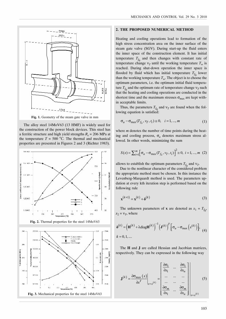
One of the most heavily loaded components of the powerblock devices is steam gate valve (SGV). The geometry ofthe SGV is presented in Figure 1.
This component is mounted on fresh and pre-heatedsteam pipelines in the power units of 360 MW. It is installedin the steam pipeline of BP1150 boiler with a steam capaci-ty of 1150 t/h. The aggressive working environment causehigh stresses in the element. The SGV is designed for thepressure pw = 18 MPa and the steam temperature Tw = 540 oC.Extreme working conditions of the SGV require employingspecial alloy steels in the construction. The material appliedmust withstand high working temperature and pressurewhile operating. It is important that the material propertiesare retained within the wide temperature range, especially atthe yield strength Re.
103
��������� ��� �������� 3�) � 45� �� � 6� 4787
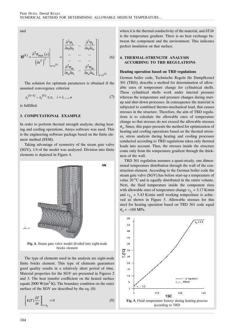
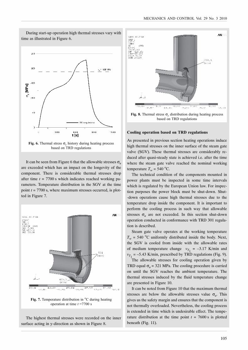
The alloy steel 14MoV63 (13 HMF) is widely used forthe construction of the power block devices. This steel hasa ferritic structure and high yield strengths Re = 206 MPa atthe temperature T = 500 oC. The thermal and mechanicalproperties are presented in Figures 2 and 3 (Richter 1983).
�� � ���������������������� �
Heating and cooling operations lead to formation of thehigh stress concentration area on the inner surface of thesteam gate valve (SGV). During start-up the fluid entersthe inner space of the construction element. It has initialtemperature Tf0
and then changes with constant rate oftemperature change νT until the working temperature Tw isreached. During shut-down operation the inner space isflooded by fluid which has initial temperature Tf0
lowerthan the working temperature Tw. The object is to choose theoptimum parameters, i.e. the optimum initial fluid tempera-ture Tf0
and the optimum rate of temperature change νT suchthat the heating and cooling operations are conducted in theshortest time and the maximum stresses σmax are kept with-in acceptable limits.
Thus, the parameters Tf0 and νT are found when the fol-
lowing equation is satisfied:
0max ( , , ) 0, 1, ...,a f T iT v t i mσ − σ ≅ = (1)
where m denotes the number of time points during the heat-ing and cooling process, σa denotes maximum stress al-lowed. In other words, minimizing the sum
0
2max1( ) ( , , ) 0, 1, ...,m
a f T iiS x T v t i m=⎡ ⎤= σ − σ ≅ =⎣ ⎦∑ (2)
allows to establish the optimum parameters Tf0 and νT.
Due to the nonlinear character of the considered problemthe appropriate method must be chosen. In this instance theLevenberg-Marquardt method is used. The parameters up-dation at every kth iteration step is performed based on thefollowing rule
( ) ( ) ( )1k k k+ = +x x � (3)
The unknown parameters of x are denoted as x1 = Tf0,
x2 = νT, where
( ) ( ) ( )( ) ( ) ( )1( ) ( )
maxdiag ,
0,1, ....
Tk k k k ka x
k
−⎡ ⎤= + λ σ − σ⎢ ⎥⎣ ⎦
=
� � � �
(4)
The H and J are called Hessian and Jacobian matrices,respectively. They can be expressed in the following way
( ) ( )( )
( )
1 1
1
max
1
...
... ... ...
... ... ...
...
k
k
n
kT
x x
m m
n x x
x x
x
x
x x
=
=
∂σ ∂σ⎡ ⎤⎢ ⎥∂ ∂⎢ ⎥⎢ ⎥∂σ
= = ⎢ ⎥∂ ⎢ ⎥
⎢ ⎥∂σ ∂σ⎢ ⎥
∂ ∂⎢ ⎥⎣ ⎦
J (5)
���������"�$"��-��&��("�,�"�$�*��"�+�)+"��%�$$
���������("�$�)�#��#"���",�&����("�,�"")�89��3:6
���������"'(�%�'�)�#��#"���",�&����("�,�"")�89��3:6
104
������ ���� �� ��� ����
�������� ������� ���� ������������ �������� ������ ���������
and
( ) ( )
( ) ( )
( )
2 21 1
1 1 12
max2
2 2
1
...
... ... ...
... ... ...
...
k
k
n
k
T
x xm m
n n n x x
x x x x
x
x
x x x x
=
=
⎡ ⎤∂ σ ∂ σ⎢ ⎥
∂ ∂ ∂ ∂⎢ ⎥⎢ ⎥∂ σ ⎢ ⎥= =⎢ ⎥∂ ⎢ ⎥
∂ σ ∂ σ⎢ ⎥⎢ ⎥∂ ∂ ∂ ∂⎣ ⎦
H (6)
The solution for optimum parameters is obtained if theassumed convergence criterion
( ) ( )1 , 1, ...,k ki ix x i n+ − ≤ ε = (7)
is fulfilled.
�� ������������� �������
In order to perform thermal strength analysis, during heat-ing and cooling operations, Ansys software was used. Thisis the engineering software package based on the finite ele-ment method (FEM).
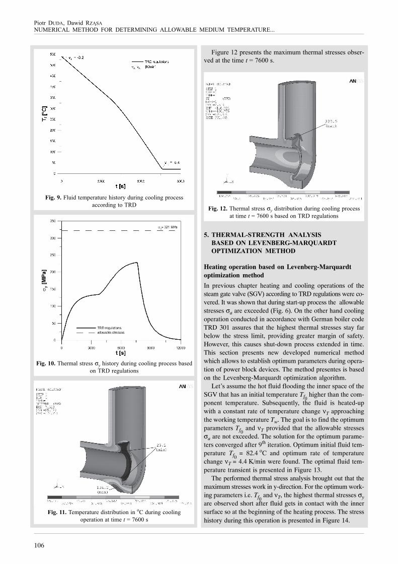
Taking advantage of symmetry of the steam gate valve(SGV), 1/4 of the model was analyzed. Division into finiteelements is depicted in Figure 4.
����������"�$�*��"�+�)+"�$��")���+��"���%���"�*(�;%��"
<��'/,�")"$"%�
The type of elements used in the analysis are eight-nodefinite bricks element. This type of elements guaranteesgood quality results in a relatively short period of time.Material properties for the SGV are presented in Figures 2and 3. The heat transfer coefficient on the heated surfaceequals 2000 W/(m2·K). The boundary condition on the outersurface of the SGV are described by the eq. (8)
0
( ) 0r r
Tk T
r =
∂⎡ ⎤ =⎢ ⎥∂⎣ ⎦(8)
where k is the thermal conductivity of the material, and ∂T/∂ris the temperature gradient. There is no heat exchange be-tween the component and the environment. This indicatesperfect insulation on that surface.
�� � ������������� � ��������
�������������������������
Heating operation based on TRD regulations
German boiler code, Technische Regeln für Dampfkessel301 (TRD), describe a method for determination of allow-able rates of temperature change for cylindrical shells.These cylindrical shells work under internal pressurewhereas the temperature and pressure changes during start-up and shut-down processes. In consequence the material issubjected to combined thermo-mechanical load, that causesstresses in the structure. Therefore, the aim of TRD regula-tions is to calculate the allowable rates of temperaturechange so that stresses do not exceed the allowable stressesσa. Since, this paper presents the method for optimization ofheating and cooling operations based on the thermal stress-es, stress analysis during heating and cooling processesconducted according to TRD regulations takes only thermalloads into account. Thus, the stresses inside the structurecome only from the temperature gradient through the thick-ness of the wall.
TRD 301 regulation assumes a quasi-steady, one dimen-sional temperature distribution through the wall of the con-struction element. According to the German boiler code thesteam gate valve (SGV) has before start-up a temperature ofvalue 20 oC and is equally distributed in the entire volume.Next, the fluid temperature inside the component riseswith allowable rates of temperature change vT1
= 3.17 K/minand vT2
= 5.43 K/min until working temperature is achie-ved as shown in Figure 5. Allowable stresses for thissteel for heating operation based on TRD 301 code equalσa = –188 MPa.
���������)1����"$#"���1�"�(�,���-��1��%*�("���%*�#��'",,
�''����%*�������
105
��������� ��� �������� 3�) � 45� �� � 6� 4787
During start-up operation high thermal stresses vary withtime as illustrated in Figure 6.
���������("�$�)�,��",,�σ$�(�,���-��1��%*�("���%*�#��'",,
<�,"���%������"*1)����%,
It can be seen from Figure 6 that the allowable stresses σa
are exceeded which has an impact on the longevity of thecomponent. There is considerable thermal stresses dropafter time t = 7700 s which indicates reached working pa-rameters. Temperature distribution in the SGV at the timepoint t = 7700 s, where maximum stresses occurred, is plot-ted in Figure 7.
����� ���"$#"���1�"���,���<1���%��%�����1��%*�("���%*
�#"�����%������$"���=>>77�,
The highest thermal stresses were recorded on the innersurface acting in y-direction as shown in Figure 8.
�����!���("�$�)�,��",,�σ$���,���<1���%��1��%*�("���%*�#��'",,
<�,"���%������"*1)����%,
�""#�$��"%&'()�"$�*(+&,�"$����'&�-#()�"$+
As presented in previous section heating operations inducehigh thermal stresses on the inner surface of the steam gatevalve (SGV). These thermal stresses are considerably re-duced after quasi-steady state is achieved i.e. after the timewhere the steam gate valve reached the nominal workingtemperature Tw = 540 oC.
The technical condition of the components mounted inpower plants must be inspected in some time intervalswhich is regulated by the European Union law. For inspec-tion purposes the power block must be shut-down. Shut--down operations cause high thermal stresses due to thetemperature drop inside the component. It is important toperform the cooling process in such way that allowablestresses σa are not exceeded. In this section shut-downoperation conducted in conformance with TRD 301 regula-tion is described.
Steam gate valve operates at the working temperatureTw = 540 oC uniformly distributed inside the body. Next,the SGV is cooled from inside with the allowable ratesof medium temperature change vT1
= –3.17 K/min andvT1
= –5.43 K/min, prescribed by TRD regulations (Fig. 9).The allowable stresses for cooling operation given by
TRD equal σa = 321 MPa. The cooling procedure is carriedon until the SGV reaches the ambient temperature. Thethermal stresses induced by the fluid temperature changeare presented in Figure 10.
It can be noted from Figure 10 that the maximum thermalstresses are below the allowable stresses value σa. Thisgives us the safety margin and ensures that the component isnot thermally overloaded. Nevertheless, the cooling processis extended in time which is undesirable effect. The tempe-rature distribution at the time point t = 7600 s is plottedbeneath (Fig. 11).
106
������ ���� �� ��� ����
�������� ������� ���� ������������ �������� ������ ���������
�����.���)1����"$#"���1�"�(�,���-��1��%*�'��)�%*�#��'",,
�''����%*�������
������/���("�$�)�,��",,�σ$�(�,���-��1��%*�'��)�%*�#��'",,�<�,"�
�%������"*1)����%,
����������"$#"���1�"���,���<1���%��%�����1��%*�'��)�%*
�#"�����%������$"���=�>:77�,
��*1�"�84�#�","%�,��("�$�?�$1$��("�$�)�,��",,",��<,"�;
+"������("���$"���=�>:77�,
����������("�$�)�,��",,�σ$���,���<1���%��1��%*�'��)�%*�#��'",,
�����$"���=�>:77�,�<�,"���%������"*1)����%,
�� � ������������� � ��������
0���������1��0�������2���� 3
������4������ ��� �
Heating operation based on Levenberg-Marquardtoptimization method
In previous chapter heating and cooling operations of thesteam gate valve (SGV) according to TRD regulations were co-vered. It was shown that during start-up process the allowablestresses σa are exceeded (Fig. 6). On the other hand coolingoperation conducted in accordance with German boiler codeTRD 301 assures that the highest thermal stresses stay farbelow the stress limit, providing greater margin of safety.However, this causes shut-down process extended in time.This section presents new developed numerical methodwhich allows to establish optimum parameters during opera-tion of power block devices. The method presentes is basedon the Levenberg-Marquardt optimization algorithm.
Let’s assume the hot fluid flooding the inner space of theSGV that has an initial temperature Tf0
higher than the com-ponent temperature. Subsequently, the fluid is heated-upwith a constant rate of temperature change νT approachingthe working temperature Tw. The goal is to find the optimumparameters Tf0
and νT provided that the allowable stressesσa are not exceeded. The solution for the optimum parame-ters converged after 9th iteration. Optimum initial fluid tem-perature Tf0 = 82.4 oC and optimum rate of temperaturechange νT = 4.4 K/min were found. The optimal fluid tem-perature transient is presented in Figure 13.
The performed thermal stress analysis brought out that themaximum stresses work in y-direction. For the optimum work-ing parameters i.e. Tf0
and νT, the highest thermal stresses σyare observed short after fluid gets in contact with the innersurface so at the beginning of the heating process. The stresshistory during this operation is presented in Figure 14.

107
��������� ��� �������� 3�) � 45� �� � 6� 4787
����������#��$1$�&)1����"$#"���1�"�(�,���-��1��%*
("���%*�#��'",,
����������("�$�)�,��",,�σ$�(�,���-��1��%*�("���%*�#��'",,�<�,"�
�%��#��$�@����%�$"�(����%�'�$#���,�%� ��(������"*1)����%,
����������("�$�)�,��",,�(�,����",�&�����&&"�"%���%����)�&)1��
�"$#"���1�",��%�����",��&��"$#"���1�"�'(�%*"
Once the initial fluid temperature Tf0 and temperature
change rate νT are higher than optimum, the allowablestresses are exceeded (Fig. 15).
Temperature distribution inside the component at timet = 500 s is shown in Figure 16.
Figure 17 presents thermal stress σy distribution insidethe SGV at the beginning of the heating process for opti-mum working parameters.
Thermal stresses acting in different direction are presen-ted in Figures 18 and 19.
����������"$#"���1�"���,���<1���%��%�����&�"����=�A77B,
������ ���("�$�)�,��",,�σ$���,���<1���%��%�����&�����=�A77�,
������!���("�$�)�,��",,�σ%���,���<1���%��%�����&�����=�A77�,
108
������ ���� �� ��� ����
�������� ������� ���� ������������ �������� ������ ���������
������.���("�$�)�,��",,���,���<1���%��%�����&�����=�A77�,
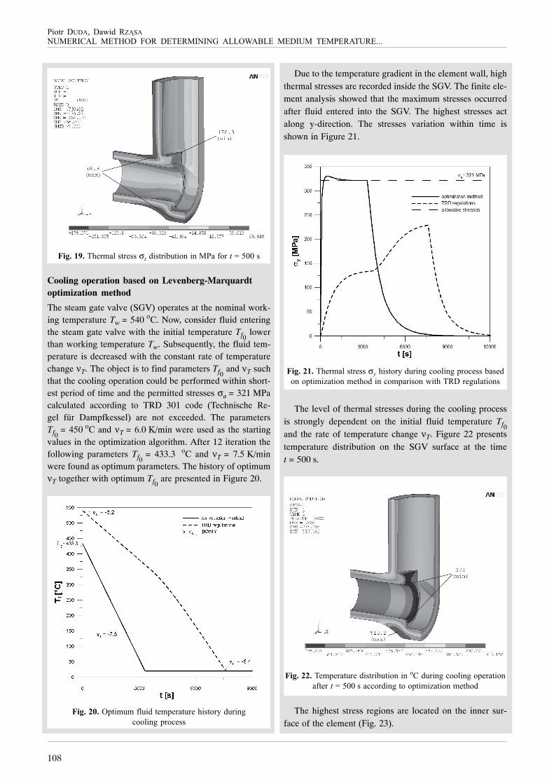
Cooling operation based on Levenberg-Marquardtoptimization method
The steam gate valve (SGV) operates at the nominal work-ing temperature Tw = 540 oC. Now, consider fluid enteringthe steam gate valve with the initial temperature Tf0
lowerthan working temperature Tw. Subsequently, the fluid tem-perature is decreased with the constant rate of temperaturechange νT. The object is to find parameters Tf0
and νT suchthat the cooling operation could be performed within short-est period of time and the permitted stresses σa = 321 MPacalculated according to TRD 301 code (Technische Re-gel für Dampfkessel) are not exceeded. The parametersTf0
= 450 oC and νT = 6.0 K/min were used as the startingvalues in the optimization algorithm. After 12 iteration thefollowing parameters Tf0
= 433.3 oC and νT = 7.5 K/minwere found as optimum parameters. The history of optimumνT together with optimum Tf0
are presented in Figure 20.
������/���#��$1$�&)1����"$#"���1�"�(�,���-��1��%*
'��)�%*�#��'",,
Due to the temperature gradient in the element wall, highthermal stresses are recorded inside the SGV. The finite ele-ment analysis showed that the maximum stresses occurredafter fluid entered into the SGV. The highest stresses actalong y-direction. The stresses variation within time isshown in Figure 21.
����������("�$�)�,��",,�σ$�(�,���-��1��%*�'��)�%*�#��'",,�<�,"�
�%��#��$�@����%�$"�(����%�'�$#���,�%� ��(������"*1)����%,
The level of thermal stresses during the cooling processis strongly dependent on the initial fluid temperature Tf0and the rate of temperature change νT. Figure 22 presentstemperature distribution on the SGV surface at the timet = 500 s.
����������"$#"���1�"���,���<1���%��%�����1��%*�'��)�%*��#"�����%
�&�"����=�A77B,��''����%*�����#��$�@����%�$"�(��
The highest stress regions are located on the inner sur-face of the element (Fig. 23).

109
��������� ��� �������� 3�) � 45� �� � 6� 4787
����������("�$�)�,��",,�σ$���,���<1���%��%�����&�����=�A77�,
�1��%*�'��)�%*��#"�����%
�� ���������
The thermal-strengths analysis revealed that high thermalstresses are formed during heating and cooling operationsof the steam gate valve. During start-up phase, based on theGerman boiler regulations, thermal stresses go over thestress limit σa. In the case of shut-down phase they are keptfar below the allowable stresses σa, but the operation isextended in time.
This paper presented the new numerical method thatallows to estimate optimum heating and cooling parametersbased on the thermal stress limitation. It was shown thatoptimum parameters allows to minimize start-up and shut-down operation time while keeping the maximum stresseswithin permitted limit. Presented method will be used inalgorithm where thermal stresses in the construction arelimited to allowable value. The new method is of great prac-tical significance and can be implemented in the industry,wherever the heating and cooling processes take place. The
optimum working parameters extend the longevity of thecomponents, ipso facto, allows to operate in a cost-effectiveway. Safety regulations on power block devices are obeyedby conforming with TRD 301 code.
�56$"7#&,�8&$)+
The authors would like to acknowledge the financial sup-port of Ministry of Science and Higher Education inPoland. The investigations presented in the current paperhave been partially supported by the research projectNo PBZ-MEiN-4/2/2006.
�&9&'&$5&+
�1���� ��� ��%�'/��� �477C��2�����������������#�������#��� �
������������#��������� ����' ��%�"�%����%�)���%&"�"%'"��%��%*�%";
"��%*��#��$�@����%��%*�#��477C�������"�D�%"��������@�)��D1%"�477C�
D�,"��"�,/�+��,�E���������# �A4�F�%����C�#�*",G
�1���� ����)"��D �4775�������������� ������������������ ��������
$� ������� �� ���� ����� ������ �� ���� � �� ���� � �%�"�%����%�)
D�1�%�)��&��"����%����,,����%,&"���+�) �A4��## �8A8>E8A49
��",,�� � ���"1/�),/-�� ��3"��"�)�%*�� � ���)�%%"�-�� � �477>��3��� �
���� �������1� *��� � �� �� ���������� ������#�� 6��� "� �� ��$<���*"
%�+"�,��-���",,����$<���*"������;87H�7A48CC7:CC
��'(�"��� �85C6��6�$�����������'�#�������������A��������� ��*����
��� ���A#�#���� � ��%%",$�%%� ���,'(1%*<"��'(�"� 567�� �I,,");
���&
�1,�%� ����%�,@/�" �'@�� ����#/��� ��J1/� �'@�� �����1),/��� �477A�
��������� �������������������� ������ �������������
��������� ������� � ��!���%*�",,��&��("�$�)����",,",����"%%���1;
,��������-�477A��## �94AE94C
�"<"��� � ����)��� D �85C5��3���� ���# ���� �D�(%���)"-K��%,�
�" �L��/������;87H�79>8:8>:78
��)"�� D ���1���� � 477:������#��� ������� ��� �������� ��������
��������#��%*"�;3"�)�*���"�)�%;�"��")<"�*������;87H�6A97669>7M
��)"��D ���@�"� ��� �477>�������������� ����� ���#������������
���������� ��� ���� �#������#�������#�������� �����������
������ ����' �>�(� �%�"�%����%�)���%*�",,��%��("�$�)����",,",�
���#"������ �%��D1%"�477>��+�) �4��## �96>E997
��)"��� ����)"��D �4775��2������������#�������������� ��%�"�%����%�)�D�1�;
%�)��&��"����%����,,����%,&"���+�) �A4��## �466AE4694
���� 678� F85C:G� �"'(%�,'("� �"*")%� &I�� ��$#&/",,")�� ���)� �"-$�%,
3"�)�*�� .N)%� 1%�� �"1�(;3"�)�*�� �"�)�%�� ����;87H� 69A44A948:�
## �5CE86C