mech3423 1516 10-refrigeration
TRANSCRIPT

Refrigeration Systems
Dr. Sam C. M. HuiDepartment of Mechanical Engineering
The University of Hong Kong
E-mail: [email protected]
Jan 2016
MECH3423 Building Services Engineering IIhttp://me.hku.hk/bse/MECH3423/

Contents
• Introduction
• Refrigerants
• Refrigeration Cycles
• Refrigeration Systems
High Temperature Reservoir
Low Temperature Reservoir
R Work Input
Heat Absorbed
Heat Rejected
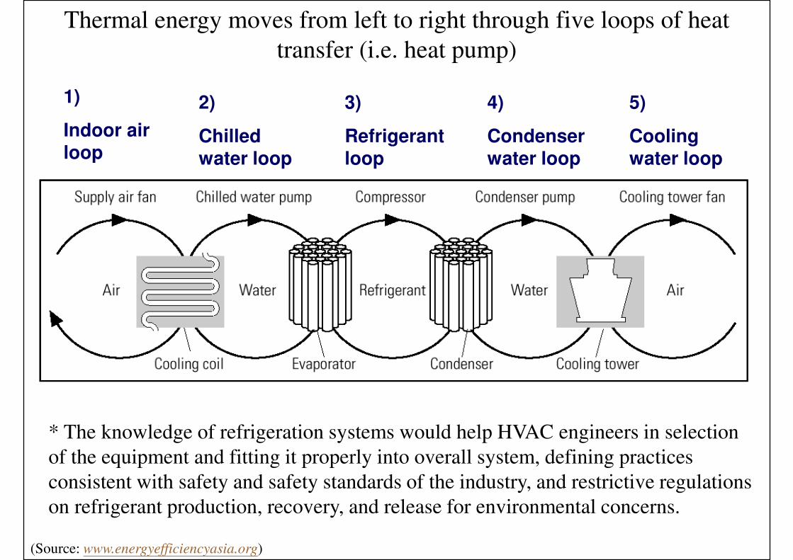
Thermal energy moves from left to right through five loops of heat
transfer (i.e. heat pump)
(Source: www.energyefficiencyasia.org)
1)
Indoor air loop
2)
Chilled water loop
3)
Refrigerant loop
4)
Condenser water loop
5)
Cooling water loop
* The knowledge of refrigeration systems would help HVAC engineers in selection
of the equipment and fitting it properly into overall system, defining practices
consistent with safety and safety standards of the industry, and restrictive regulations
on refrigerant production, recovery, and release for environmental concerns.

Introduction
• Refrigeration
• The cooling effect of the process of extracting heat
from a lower temperature heat source, a substance
or cooling medium, and transferring to a higher
temperature heat sink, to maintain the temperature
of the heat source below that of surroundings
• Refrigeration systems
• Combination of components, equipment & piping
connected to produce the refrigeration effect

Introduction
• Refrigeration systems
• Vapour compression
• Mechanical refrigeration using compressors, condensers and
evaporators
• Absorption
• Produce refrigeration effect by thermal energy input
• Liquid refrigerant produce refrigeration during evaporation; the
vapour is absorbed by an aqueous absorbent
• Gas expansion (air or gas cycle)
• Air or gas is compressed to a high pressure; it is then cooled by
surface water or air and expanded to low pressure to produce
refrigeration effect
• For air conditioning and pressurization of aircrafts

Vapour compression system
Absorption system
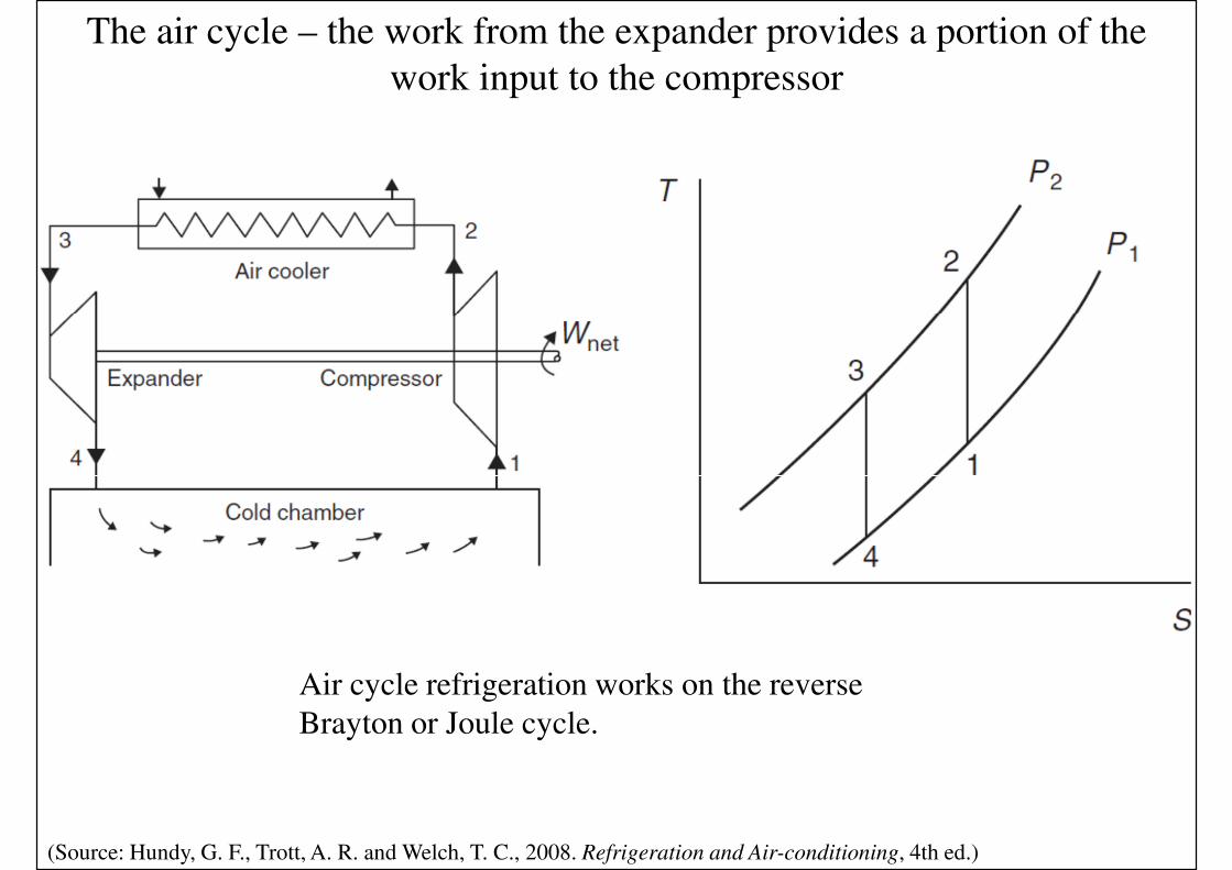
The air cycle – the work from the expander provides a portion of the
work input to the compressor
(Source: Hundy, G. F., Trott, A. R. and Welch, T. C., 2008. Refrigeration and Air-conditioning, 4th ed.)
Air cycle refrigeration works on the reverse
Brayton or Joule cycle.

Introduction
• Terminology
• Refrigerant:
• A primary working fluid to produce refrigeration in a refrigeration system
• Cooling medium:
• Working fluid cooled by refrigerant during evaporation to transport refrigeration from a central plant to remote equipment
• Liquid absorbent:
• Working fluid to absorb vaporised refrigerant (water) after evaporation in an absorption refrigeration system

Refrigerants
• Numbering system for refrigerants
• For hydrocarbons & halocarbons (halogenated)
• ANSI/ASHRAE Standard 34
• 1st digit: number of unsaturated carbon-carbon bonds
• 2nd digit: number of carbon atoms minus one
• 3rd digit: number of hydrogen atoms plus one
• Last digit: number of fluorine atoms
• For example, R-11 = CFCl3 ; R-12 = CF2Cl2 ; R-22 = CHF2Cl; R-123 = CHCl2CF3
• Chlorofluorocarbons (CFCs)
• Contains only chlorine, fluorine & carbon atoms
• Cause ozone depletion & global warming
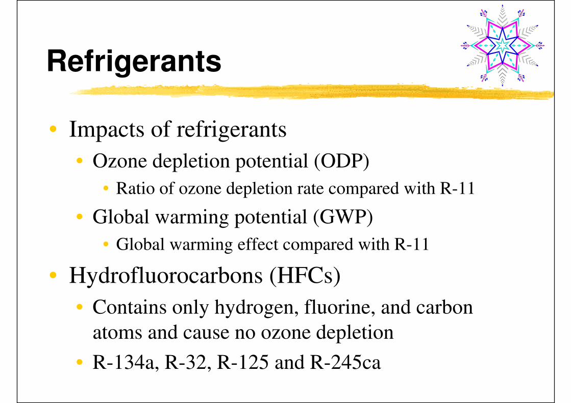
Refrigerants
• Impacts of refrigerants
• Ozone depletion potential (ODP)
• Ratio of ozone depletion rate compared with R-11
• Global warming potential (GWP)
• Global warming effect compared with R-11
• Hydrofluorocarbons (HFCs)
• Contains only hydrogen, fluorine, and carbon
atoms and cause no ozone depletion
• R-134a, R-32, R-125 and R-245ca

Ozone depletion in the atmosphere

Refrigerants
• HFC’s azeotropic blends or azeotropic (共沸)• Azeotropic = mixture of multiple refrigerants that evaporate
& condense as a single substance and do not change in volumetric composition or saturation temperature when evaporate or condense
• ASHRAE assign numbers 500 to 599 for azeotropic
• Such as R-507 (blend of R-125/R-143)
• HFC’s near azeotropic• Mixture of refrigerants whose characteristics are near those
of an azeotropic• ASHRAE assign numbers 400 to 499 for zeotropic
• Such as R-404A (R-125/R-134a/R-143a) and R-407B (R-32/R-125/R-134a)

Refrigerants
• Zeotropic or non-azeotropic
• Including near azeotropic
• Show a change in composition due to the difference
between liquid & vapour phases, leaks, and the
difference between charge & circulation
• A shift in composition causes change in
evaporating & condensing temperature/pressure
• Middle between dew point & bubble point is often
taken as evap. & cond. temp. for the blends

Refrigerants
• Hydrochlorofluorocarbons (HCFCs)
• Contain hydrogen, chlorine, fluorine & carbon atoms and are not fully halogenated
• Smaller lifetime in atmosphere than CFCs & cause far less ozone depletion (ODP = 0.02 to 0.1)
• R-22, R-123, R-124
• HCFC’s near azeotropic & HCFC’s zeotropic
• Blends of HCFCs with HFCs
• Transitional or interim refrigerants, scheduled for restricted production starting in 2004

Refrigerants
• Inorganic compounds
• ASHRAE assign numbers R-700 to -799
• Ammonia (NH3) R-717, carbon dioxide (CO2) R-744, air
R-729, water (H2O) R-718, sulphur dioxide (SO2) R-764
• Do not deplete ozone layer
• CFCs
• Long lifetime (centuries)
• Cause ozone depletion (ODP = 0.6 – 1)
• Such as R-11, R-12, R-113, R-114, R-115
(See also: List of refrigerants - Wikidpedia http://en.wikipedia.org/wiki/List_of_refrigerants)

Refrigerants
• Halons (or BFCs)
• Contain bromide, fluorine & carbon atoms
• R-13B1, R-12B1 (used in very low temp. systems)
• Very high ozone depletion (ODP for R-13B1 =10)
• Montreal Protocol (1987) & Vienna Convention (1985)
• Restrict the production & consumption of CFCs & BFCs
• Phase-out of CFCs, BFCs, HCFCs and their blends

Time line for refrigerants
(Source: Hundy, G. F., Trott, A. R. and Welch, T. C., 2008. Refrigeration and Air-conditioning, 4th ed.)

Refrigerants
• In early 1990s
• R-11: widely used for centrifugal chillers
• R-12: for small & medium systems
• R-22: for all vapour compression systems
• R-502 (CFC/HCFC blend) for low-temp. systems
• Hong Kong
• Ozone Layer Protection Ordinance
• See website of Environmental Protection Dept.
http://www.epd.gov.hk/epd/english/olp/

(Source: http://www.epd.gov.hk/epd/english/environmentinhk/air/air_maincontent.html)
Ozone Layer Protection Ordinance in Hong Kong

Refrigerants
• Alternative refrigerants
• R-123 (HCFC, ODP = 0.02), replace R-11
• R-245a (ODP = 0), replace R-11 (longer term?)
• R-134a (HFC, ODP = 0), replace R-12
• Not miscible with mineral oil, synthetic lubricant is used
• R404A (R-125/R-134a/143a) and R-407C
• HFCs near azeotropic, ODP = 0; long-term alternatives to R-22
• R-507 (R-125/R-134a)
• HFC’s azeotropic, ODP = 0; long-term alternatives to R-502
• Synthetic lubricant oil is used
• R-402A (R-22/R-125/R-290) as short-term drop-in replacement

Refrigerants
• Required properties of refrigerants
• Safety (ANSI/ASHRAE Standard 34-1992)
• Toxicity: Class A and Class B
• Flammability:
• Class 1 – no flame propagation
• Class 2 – lower flammability
• Class 3 - higher flammability
• Such as “A1” Group: R-134a & R-22; “B2”: ammonia
• Effectiveness of refrigeration cycle (kW/TR)
• Lubricant oil miscibility
• Compressor displacement

Refrigerants
• Desired properties:
• Evaporative pressure > atmospheric
• Non-condensable gas will not enter the system
• Lower condensing pressure (lighter construction)
• High thermal conductivity (better heat transfer)
• Dielectric constant compatible w/ air
• An inert refrigerant (avoid corrosion, erosion)
• Refrigerant leakage can be detected
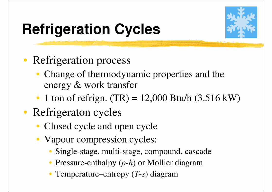
Refrigeration Cycles
• Refrigeration process
• Change of thermodynamic properties and the energy & work transfer
• 1 ton of refrign. (TR) = 12,000 Btu/h (3.516 kW)
• Refrigeraton cycles
• Closed cycle and open cycle
• Vapour compression cycles:
• Single-stage, multi-stage, compound, cascade
• Pressure-enthalpy (p-h) or Mollier diagram
• Temperature–entropy (T-s) diagram

The ideal reversed Carnot cycle:
(a) circuit and (b) temperature–entropy (T-s) diagram
(Source: Hundy, G. F., Trott, A. R. and Welch, T. C., 2008. Refrigeration and Air-conditioning, 4th ed.)

Refrigeration Cycles
• Ideal single-stage cycle
• Isentropic compression, pressure losses neglected
• qrf = refrigeration capacity
• Win = work input to compressor
• Coefficient of performance (COP)
• COP = qrf / Win
• Refrigerator: produce refrigeration effect
• Heat pump: produce heating effect
• Subcooling and superheating

Condenser
Evaporator
High Pressure
Side
Low Pressure
Side
CompressorExpansion Device
12
3
4
Refrigeration cycle -- vapour compression cycle
(Video: Refrigeration Cycle Video Animation (1:30) http://www.youtube.com/watch?v=MqnyaUNxs9A)

Simple vapour compression cycle
with pressure and enthalpy values for R134a
(Source: Hundy, G. F., Trott, A. R. and Welch, T. C., 2008. Refrigeration and Air-conditioning, 4th ed.)

The temperature rise or ‘ lift ’ of the refrigeration cycle is increased by
temperature differences in the evaporator and condenser
(Source: Hundy, G. F., Trott, A. R. and Welch, T. C., 2008. Refrigeration and Air-conditioning, 4th ed.)

Refrigeration cycle -- vapour compression cycle
4 1
23
Enthalpy kJ/kg
System COP normally includes all the power
inputs associated with the system, i.e. fans and
pumps in addition to compressor power.
A ratio of System COP to Carnot COP (for the
process) is termed system efficiency index,
SEI.


Refrigeration Cycles
• Two-stage compound systems w/ flash cooler
• Multi-stage compression connected in series
• Higher compression efficiency, greater refrig. effect
• Compressor ratio
• Flash cooler: an economizer to subcool liquid
refrigerant to saturated temperature
)())(1(
))(1(COP
3412
91
in hhhhx
hhx
W
qref
ref−+−−
−−==

Two-stage compound systems w/ flash cooler
* Where the ratio of suction to discharge pressure is high enough to
cause a serious drop in volumetric efficiency or an unacceptably high
discharge temperature, vapour compression must be carried out in
two or more stages.

Refrigeration Cycles
• Casade system characteristics
• Two independently operated single-stage systems
• Connected by a cascade condenser
• Main advantages
• Different refrigerants, oils and equipment can be used
• Disadvantages: more complicated
)()(
)(COP
56'12
41
in hhmhhm
hhm
W
q
hl
lref
ref−+−
−==
&&
&

Cascade system

Refrigeration Cycles
• Absorption cycle
• Such as ammonia and lithium bromide systems
• Absorption of ammonia gas into water, and of water
vapour into lithium bromide
• Refrigerant vapour from the evaporator is drawn into
the absorber by the liquid absorbant. The liquor is then
pumped up to condenser pressure and the vapour is
driven off in the generator by direct heating
• The heat energy to the generator may be any form of
low-grade energy such as oil, gas, hot water or steam, or
from solar radiation
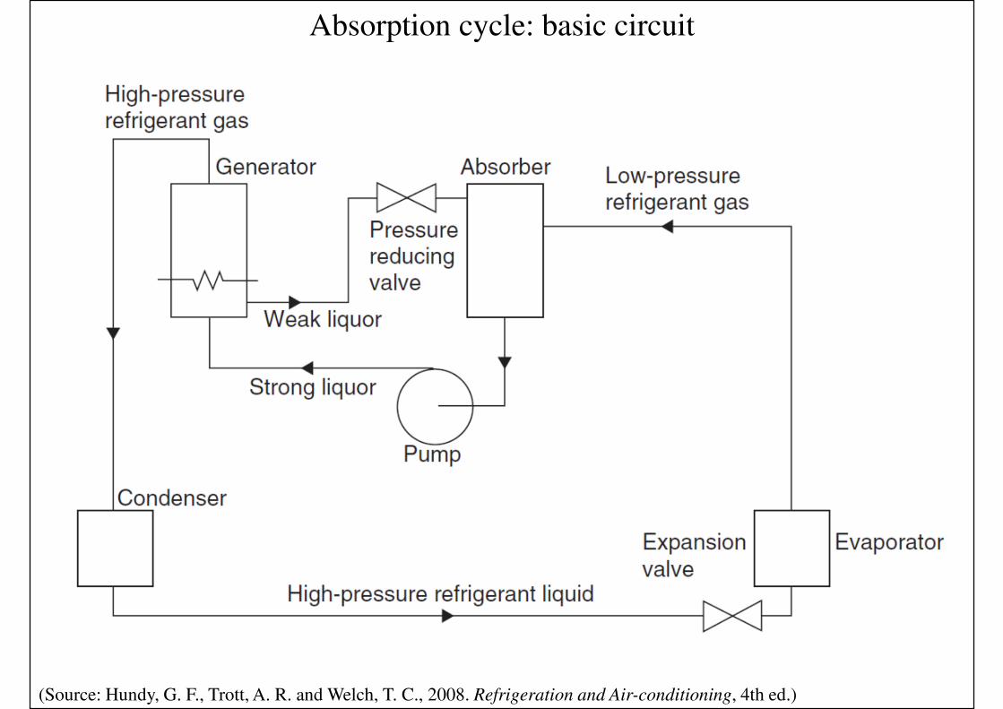
Absorption cycle: basic circuit
(Source: Hundy, G. F., Trott, A. R. and Welch, T. C., 2008. Refrigeration and Air-conditioning, 4th ed.)

Vapour absorption refrigeration
Condenser Generator
Evaporator
AbsorberCold Side
Hot Side

Refrigeration Systems
• Common types of compressors used in chillers
(HVAC refrigeration plant):
• Reciprocating -- piston-style, positive displacement
• Rotary screw -- positive displacement; 2 meshing
screw-rotors rotate in opposite directions
• Scroll -- positive displacement; one spiral orbits
around a second stationary spiral
• Centrifugal -- raise the pressure by imparting
velocity or dynamic energy, using a rotating
impeller, and converting it to pressure energy

Common types of compressors used in chillers
Reciprocating Rotary screw
Scroll Centrifugal

Refrigeration Systems
• Arrangement of compressor motor or external
drive:
• Open type
• Hermetic (or sealed) type
• Semi-hermetic (or semi-sealed) type

Refrigeration Systems
• Common refrigeration systems in HVAC
• Direct expansion (DX) systems & heat pumps
• Centrifugal chillers
• Screw chillers
• Absorption systems
• Either single-stage or multistage
• Compressor lubrication
• Use mineral or synthetic oil
• Use magnetic bearings (oil-free chiller/compressor)

Refrigeration Systems
• Direct expansion (DX) systems
• Part of the packaged air-conditioning system
• R-22 and R-134a widely used
• Range 3-100 TR
• Components & accessories
• Compressor(s): reciprocating and scroll
• Condensers
• Refrigeration feed
• Oil lubrication
• Refrigerant piping

Direct expansion (DX) system (air-cooled condenser)
Cooling mode Heating mode

Refrigeration Systems
• Direct expansion (DX) systems (cont’d)
• Capacity control
• On-off control
• Cylinder unloader
• Speed modulation
• Safety control
• Low- & high-pressure control
• Low-temperature control
• Motor overload control
• Pump-down control
• Full- and part-load operation

Capacity control of a DX system

Refrigeration Systems
• Heat pumps
• Three types:
• Air-source (air-to-air)
• R-22 often used, range 1.5 to 40 TR
• Water-source
• Ground-coupled
• Extract energy from ground, water, or ambient air
• Cooling and heating mode operartion
• Winter may require defrosting
• High COP & EER (energy efficiency ratio)


Refrigeration Systems
• Centrifugal chillers
• Chiller = a refrigeration machine using a liquid
cooler as an evaporator to produce chilled water
• R-11, R-12, R-22 were used
• R-11 replaced by R-123
• R-12 replaced by R-134a
• System components
• Centrifugal compressor, evaporator, condenser, flash
cooler, orifice plates & float valves, purge unit (optional)

Two-stage water-cooled centrifugal chiller

Refrigeration Systems
• Centrifugal chillers (cont’d)
• Performance rating: ARI Standard 550
• COP and Integrated part-load value (IPLV)
• Water-cooled chillers: COP = 5 (= 0.7 kW/TR)
• Air-cooled chillers: COP = 2.5 to 2.8 (1.26-1.4 kW/TR)
• Capacity control:
• Inlet vanes and variable compressor speed
• Centrifugal compressor performance map
• Partload operation

Refrigeration Systems
• Centrifugal chillers (cont’d)
• Specific controls
• Chilled water leaving temperature and reset
• Condenser water temperature control
• On/off of multiple chillers based on measured coil load
• Air purge control
• Safety controls e.g. oil pressure, freezing protection, etc.
• Incorporating heat recovery
• Double-bundle condenser

Refrigeration Systems
• Screw chillers
• Helical rotary chiller: use screw compressor
• Twin-screw compressors are widely used
• Capacity 100 to 1000 TR
• Variable volume ratio
• Economizer
• Similar to a two-stage compound system w/ flash cooler
• Oil separation, oil cooling and oil injection
• Oil slugging is not a problem

Twin-screw compressor