mechanical analysis of a vertical scanning system for 3d ... · pdf filemechanical analysis of...
TRANSCRIPT
Mechanical Analysis of a Vertical Scanning System for 3D Images
Acquisition with Microcontroller-based Electronic Design
J. Armando Segovia1,2
, Alberto Contreras2 and Mayra P. Garduño
2
1National Institute of Nuclear Research (ININ)
Carr. Mexico-Toluca s/n, La Marquesa, Ocoyoacac, C.P. 52750. MEXICO 2Technological Institute of Toluca
Av. Inst. Tec. s/n, Metepec, Edo. de Mexico, C. P. 52140. MEXICO
[email protected], [email protected], mgarduñ[email protected]
Abstract: - Herein are presented in detail the tasks that were developed to carry out a project that had as aim
updating and improving the perception system of a Pioneer 3-AT mobile robot to enhance its navigation control
by means of a mechanical system to let a laser range finder scanning and acquiring 2.5D and 3D images of the
robot’s environment. The system developed is a mechanism that is able to put in start position and to tilt automatically a laser range finder LMS200 with high precision, because the range of repetitive accuracy is very
important to get good images. This precision was obtained with the aid of different parts that work together and
with the best performance into its correspondent area; electronic area (control and communication circuits), mechanical area (stepper motor and mechanical design) and informatics area (acquisition and data processing).
The system was developed to be an inexpensive device, using the most common elements, as a Microchip’s
microcontroller, which are easy to program and there are many models to choose the one that could fit our needs and budget, small elements and many job features, for example the PWM module, communication ports
by USART and USB, and A/D channels, very important characteristics to control a stepper motor.
Key-Words: - 3D Scanner, Telemeter, Microcontroller, Navigation, mobile robot, Stepper Motor, LMS200
Laser Range Finder.
1 Introduction The work described here is focused to develop a low
cost navigation system, profiting from the existence
of commercial devices, materials, parts and also using recycling materials.
There is a lot of techniques used to solve the
problem of mobile robots navigation, and they depend on the use of different sensors, but to obtain
good results, many times it is necessary to use two
or more sensors concurrently.
For example, when a robot uses ultrasonic sensor, it can know only the distance to the obstacle.
Same situation appears when it uses a light sensor,
IR sensor, or point laser sensor, but with this configuration the robot can’t identify what is the
objects or, it needs specific characteristics to do it.
Other device widely used is the video camera, but with this one, colors (or intensity) and some
other parameters as texture can only be detected, but
determining the distance to the objects requires a lot
of processing using two or more cameras. There exist many advantages to use range data provided by
3D laser range sensors, because is achieve a better
accuracy of the object poses compared to stereo
camera solutions [1]; this is the main argument to
use a laser range finder to obtain distances to the
objects. But the drawback of only 2D proximity
information is that it may cause problems with
overhanging objects (e.g. chairs, tables or stairways) [2].
The advantage of using a modified 2D range
finder to generate 3D images is that it takes the distances and with them the robot can find and
identify obstacles.
3D map building for mobile robots under
cluttered indoor environments remains a challenge. The problem lies in two aspects: map consistency
and computational complexity [3].
Vision is the most important source of information; this provides interaction with a 3D
world. Also, if it would be possible providing to the
machines with the same kind of vision, it could be possible that this perception model could be linked
with a specified set of actions like identifying,
grasping and avoiding objects, common tasks in the
sensed 3D environment [4, 5]. This paper presents the principal problems and
solutions proposed to create all the components that
WSEAS TRANSACTIONS on SYSTEMS J. Armando Segovia, Alberto Contreras, Mayra P. Garduno
ISSN: 1109-2777 180 Issue 2, Volume 9, February 2010

assembled allowed built a 3D scanner using the Sick
LMS200 (Fig. 1) existing in the Mobile Robotics
laboratory of the Technological Institute of Toluca.
To make an easier study and development of the system here described, the construction of the tilting
system (TS) can be divided in three principal parts:
mechanical, electronic, and programming part; they are described in following paragraphs.
Fig. 1. Telemeter laser range finder LMS200
2 Characteristics of the project
elements The project was developed in base of a 2D SICK
telemeter laser range finder LMS200; the use of this device yields the advantage of scanning images with
great exactly, fast, and high performance of distance
measurement. To achieve this, two major principles of laser based distance measuring methods are used
in industrial applications: Triangulation and time-of-
flight (TOF). For active triangulation, the scene is
illuminated by a laser source from one direction and viewed by a sensor from the other direction. The
LMS200 operates by measuring the time of flight of
laser light pulses: a pulsed laser beam is emitted and reflected if it meets an object. The reflection is
registered by the LMS200 receiver. The time
between transmission and reception of the impulse is directly proportional to the distance between the
LMS200 and the object (time of flight). More or less
TOF and phase measurement methods are long
range technologies (over 1.0 meter) and triangulation based methods belong to close range
methods [1].
The measurement data is available in real-time for further evaluation via the data interface [6], this
data are transmitted to the host computer or the
robot computer by the serial port RS232 or RS422. In order to do that the TS could take 3D images,
one box of 3mm aluminum was made (Fig.2). In
this box the telemeter was mounted and it has the
task of maintain the LMS200 over the pivot axis to do that the TS rotate around it, tilting and scanning
one frame.
The main characteristics of the LMS200 are: field of view of 180°, operating range from 0 m to
80 m, 10 m of max range with 10 % reflectivity,
possibility of different configuration in angular
resolution at 0.25 °, 0.5 ° or 1 °, Systematic Error of
15 mm and Statistical Error 5 mm [7].
Fig.2. Box (turret) where the LMS200 is mounted.
The motion of the TS was developed with one
stepper motor and one array of toothed pulley with a
relation of movement of 1:2.5 and the main characteristics of the chosen motor are 3.5V/phase,
1.4A/Phase and 1.8deg/step.
The control of the TS was planed to use different elements, for example one microcontroller with at
least one serial port communication, one PWM, one
AD converter, so was elected the PIC16F870 as
principal central control device, and as optional central control device one PIC18F2455 that has one
USB port.
With this 3D scanner one can get images with a resolution of 0.36° or 0.72° per line in vertical
direction, and one field of view of 180° on the
horizontal.
3 Mechanical Part 3.1 Determining structure’s center of
mass and moment of inertia The first activity was to determine the center of
mass from the LMS200, and the box (turret) where the telemeter would be mounted (Fig. 3) to find the
best point to put the pivot axis that would transmit
the motion to the telemeter, creating in this way a new degree of freedom around “X” axis.
Fig. 3. Design of the TS and representation of the center of mass and
the moment of inertia
WSEAS TRANSACTIONS on SYSTEMS J. Armando Segovia, Alberto Contreras, Mayra P. Garduno
ISSN: 1109-2777 181 Issue 2, Volume 9, February 2010
The pivot must be placed on line with the
coordinates that represent the position of the center
of mass, it is very important in the design because it
is the point where the motor will receive less stress. In this activity the theory about center of mass
and moment of inertia was used, to determine
approximately the real position of this point characteristic.
Center of Gravity: The center of gravity is the
point where the resultant weight of a particles system is concentrated [8, 9].
W
Wzz
W
Wyy
W
Wxx
)~()~()~( (1)
Where:
zyx ,, represents the coordinates of the center of
gravity of a particles system. zyx ~,~,~ represents the coordinates of each particle
present in the system (centroid).
W is the sum of all the weights of all the
particles in the system.
Center of Mass: The center of mass is the point
where the mass from a particles system with a constant acceleration, for example the gravity, is
concentrate at that point [8].
m
mzz
m
myy
m
mxx
)~()~()~( (2)
Where:
m is the sum of all the masses of all the
particles in the system. m is the mass.
The difference on these two terms that sometimes are interpreted as the same is that the
second one is independent from the gravity force
[8]. Another form to explain the relationship and
difference of these terms is that the center of mass of
a particles system is used when in the calculations
the handling of the properties is related to the mass of the particles, and is used the center of gravity
when the properties are associated with the weight
of the particles [10]. Into the project it was necessary determining the
center of mass because the properties that we knew
were the mass and the density. The telemeter has a
mass of 4.5 Kg and the turret was designed and made in aluminum that has a density of 2,700
Kg/m3.
The first step to determine the center of mass was to divide the telemeter and the turret in different
regular figures to find the main characteristics of
individual forms and then combine them into a composite figure (Fig. 4).
The second part of the project was to define a
coordinate system to determine the exactly position
and dimension from every figure inside a space
(Fig. 5).
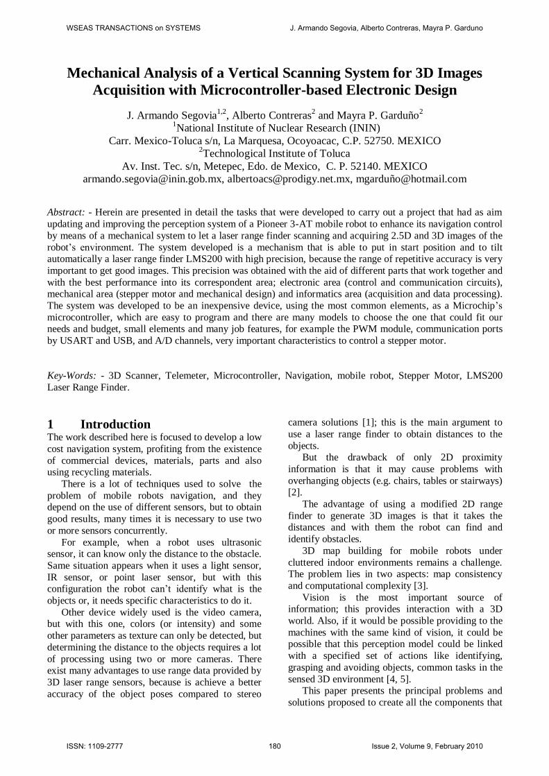
Fig. 4. Representation of the turret and telemeter LMS200 by
regular geometric figures (2B, 3B, 4B, 5B and 6B are cutting extrusion).
Equations (8) to (10) and (13) to (15) were used
to calculate the center of mass of each part, with this
result also was determined the position where the
pivot was placed in the turret by means of equation (2), with the purpose of decreasing the moment of
inertia in the TS. The results are shown in Table I.
At this point it is important to define that this method isn’t exact when the real distribution of
mass is unknown, e.g. in the telemeter, but it can be
approximated.
Fig. 5. Representation of the turret and telemeter inside of a
coordinate system of reference to help calculate the position of the
center of mass.
WSEAS TRANSACTIONS on SYSTEMS J. Armando Segovia, Alberto Contreras, Mayra P. Garduno
ISSN: 1109-2777 182 Issue 2, Volume 9, February 2010

By the previous reason, it was necessary to make
use of a complementary method to determine the
center of mass, this was the experimental method
(Fig. 6) where two or more points must be selected on the extremities of a object to use each of them as
pivot to put in equilibrium the system and then trace
a perpendicular line at the horizontal to determine the center of mass on the point where the lines
intersect.
Fig. 6. Finding the center of mass in an irregular body or with
irregular density distribution.
After obtaining the center of mass and
confirming the result, the next step was to determine
the moment of inertia to know what type of motor is necessary to give movement to the mechanism.
The moment of inertia is a measure that gives the
distribution reason of the mass in a particles system around one of its points [9]. In other words, it
represents the inertia to rotate that a body has,
knowing that it is the resistance to the acceleration,
in this case angular acceleration [11].
There are two ways to calculate the moment of inertia, doing the corresponding integrals (3) in all
the volume of the body, or using the defined
equations (4) to (7), (11), and (12), to be used in the regular bodies.
VmdVrIdmrI 22 (3)
)( ~ mDII Ixx (4)
Where:
I is the moment of inertia
r is the perpendicular distance between the spin axis and an arbitrary element dm. “the
moment arm”.
ρ density V volume
xI is the moment of inertia into a composite
figure, respect the spin axis “ X ” that crosses the center of mass.
xI~ is the moment of inertia of each figure that
composes the composite figure with respect to their spin axis “ X
~ ”, which crosses their
centroid.
ID is the distance between the “ X ” axis and
“ X~ ”, in each regular figure that form the
composite figure.
As well as there are equations to calculate the
area and volume also are defined equations to calculate the moment of inertia and the centroid in
the regular geometric figures, as follow.
)(12
1 22~ cbmI x
(5)
)(12
1 22~ acmI y
(6)
Prism )(12
1 22~ bamI z
(7)
xa
x2
~ (8)
yb
y2
~ (9)
zc
z2
~ (10)
)3(12
1 22~~ LrmII yx
(11)
2~
2
1rmI z
(12)
Cylinder xCx~ (13)
yCy~ (14)
zL
z2
~ (15)
Where:
zyx III ~~~ ,, are the moment of inertia around the
axis indicated on the subscript.
cba ,, are the width (on axis X), length (on axis Y)
and high (on axis Z) respectively in a prism.
X Y Z
Centroid of 1A 160.6 57.2 96.2 173.56032
Centroid of 1.1A 160.6 117.2 141.5 9.891072
Centroid of 2A 1.6 57.2 96.2 173.56032
Centroid of 2.1A 1.6 117.2 141.5 9.891072
Centroid of 3A 81.1 1.6 125.8 186.387264
Centroid of 4A 81.1 28.7 190.8 71.471808
Centroid of 5A 81.1 82.7 1.6 79.880256
Center of mass of
the turret81.1 44.17749811 104.1724939 704.642112
Centroid of 1B 81.1 132.2 95.7 17364.51983
Centroid of 2B 81.1 132.2 155.7 3960.335622
Centroid of 3B 81.1 158.45 66.2 7472.880675
Centroid of 4B 81.1 85.95 23.7 728.4729137
Centroid of 5B 81.1 85.95 108.7 728.4729137
Centroid of 6B 81.1 93.7 66.2 474.3577053
Centroid of 7B 81.1 136.2 23.7 174.0393484
Centroid of 8B 81.1 136.2 108.7 174.0393484
Centroid of 9B 81.1 135.7 66.2 151.9213033
Center of mass of
the LMS20081.1 108.0683195 101.2673993 4500
Center of mass of
the TS81.1 99.41831777 101.660712 5204.642112
MASS OF THE
ELEMENTS (g)
TABLE I
Position of the centroid of each regular figure that represent the turret
and the LMS200, and the center of mass of the TS.
DESCRIPTIONCOORDINATES INTO THE AXIS (mm)
WSEAS TRANSACTIONS on SYSTEMS J. Armando Segovia, Alberto Contreras, Mayra P. Garduno
ISSN: 1109-2777 183 Issue 2, Volume 9, February 2010
zyx ,, are the displacement that the figure has
respect the center of the coordinate system.
Lr, are the radius and length respectively in a
cylinder.
yx CC , are the coordinates center of the circular
face on a cylinder.
For practical cases the use of regular figures that form a composite figure is most usual and fast [8].
The following stage of the project was find the
moment of inertia of the turret and the telemeter, it
was calculated with the aid of the regular figures that compose the system and the equations (5) and
(11) corresponding with each figure that define the
turret and the telemeter considering the same coordinate system (Fig. 5), to obtain later the
moment of inertia of the whole system using
equation (4), getting the results shown in Table II. It’s important once again notate that the use of
this method isn’t exact when the real mass or
density distribution is unknown, but it will be
approximated to the real value if the center of mass is correctly calculated.
Knowing that the concept of moment of inertia
in a rotational movement and the inertial mass in a
linear movement are analogous [11], and making use of the second law of Newton, it is easy to
calculate by means of equation (16) the required
torque to move the telemeter and the turret, knowing
that the moment of inertia of the system is
0.064692783 Kg m2 and that the required max
angular acceleration is 2.61799 rad/s2, the reason of
this value is explained in section 2.2. I (16)
mIk (17)
Where:
is the torque generated by an angular
acceleration and a moment of inertia, doing
analogy to the second law of Newton in a
rotational movement.
is the angular acceleration of a body (rad/s2)
k is the radius of spin
In summary, the important data to the design
were the exactly position of the center of mass, which is on the coordinate point (81.1, 99.42,
101.66) mm respect the coordinate system of
reference (Fig.5), and the moment of inertia of the
TS in that point, which has a value of approximate 0.0647 kg·m
2.
3.2 Motor and power transmission system Other important part into the mechanical design is
the generation of movement and the transmission of it. One relevant step into the election of the system
of movement is identifying and defining what will
be the input and the output from the mechanism, for example in this case we needed as input and output
a rotational movement, with high rate of repetitive
accuracy.
There are many methods to approve these two principal characteristics, for example using one gear
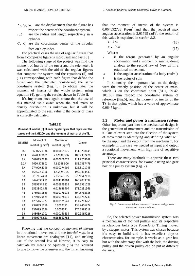
box or a pulley system (Fig. 7).
Fig. 7. Some elemental mechanisms to transmit and generate
movement in one machine.
So, the selected power transmission system was
a mechanism of toothed pulleys and its respective
synchronous belts type PowerGrip Timing moved
by a stepper motor. This system was chosen because it’s easy to build and it has excellent physics
characteristics, for example, it works as a gear box
but with the advantage that with the belt, the driving pulley and the driven pulley can be put at different
distance.
ELEMENTMoment of
inertial (g·mm2)
Moment of
inertial (kg·m2)DI(mm)
1A 669075.0336 0.000669075 111.9208649
1.1A 7620.378601 7.62038E-06 183.7337476
2A 669075.0336 0.000669075 111.9208649
2.1A 7620.378601 7.62038E-06 183.7337476
3A 274909.4099 0.000274909 125.8101745
4A 15552.50366 1.55525E-05 192.9464433
5A 21695.7438 2.16957E-05 82.71547618
1B 84740303.81 0.084740304 163.2033394
2B 6899234.681 0.006899235 204.2531028
3B 15638403.98 0.015638404 171.7231566
4B 178915.9829 0.000178916 89.15768335
5B 178915.9829 0.000178916 138.5752233
6B 125546.6727 0.000125547 114.7263265
7B 237099.6056 0.0002371 138.2466274
8B 237099.6056 0.0002371 174.2588018
9B 148639.1701 0.000148639 150.9865226
TS 64692782.91 0.064692783
TABLE II
Moment of inertial (I ) of each regular figure that represent the
turret and the LMS200, and the moment of inertial of the TS.
WSEAS TRANSACTIONS on SYSTEMS J. Armando Segovia, Alberto Contreras, Mayra P. Garduno
ISSN: 1109-2777 184 Issue 2, Volume 9, February 2010

To determining the principal dynamic behavior
of the pulley arrange, it was calculated by means of
equation (18) and (19), where the angular speed is
inversely proportional to the relation of pulleys, and the torque conduction is directly proportional to the
relation of pulleys.
out
ininout
in
out
out
in
N
N
N
N
(18)
in
outinout
out
in
out
in
N
N
N
N
(19)
Where:
ωin, ωout are the angular speed of the driving
pulley and the driven pulley respectively.
τin, τout are the torque in the driving pulley and the
driven pulley respectively. Nin, Nout are the number of teeth of each pulley,
the driving pulley and the driven pulley
respectively. The driving pulley of the mechanism has 16
teeth with a step of 0.080 inches and the driven
pulley has 40 teeth with the same step, with these data we can define the relation of movement in a
scale of 1:2.5.
The selected motor is a stepper motor because the handling of the position is easy and the precision
only depends of the step angle of the motor. The
main characteristics of the chosen motor are (as mentioned before): 3.5V/phase, 1.4A/Phase and
1.8deg/step.
In order to assure that the motor could be able to
support the load, it was put experimentally under a torsion test using a mass of 2 Kg. placed at a
distance of 1cm from the motor’s shaft and using a
work frequency of 208 Hz to produce a speed rotation around 62.4 RPM, because this is the
needed to generate around 25 RPM (150°/s) of
speed rotation on the telemeter LMS200 as in the 3-
D Sweeping Laser Range-Finder commercial model. The result of the test was satisfactory obtaining a
torque of 0.1962 N m (27.78oz in) in the motor and
in the driven pulley a torque of 0.4983 N m (70.55
oz in) that is more than the torque necessary to move the telemeter, which was calculated using (16)
obtaining 0.1694 N m (23.98 oz in).
4 Electronic Part The second part of the development of the TS had as objective designing the circuit and the printed
circuit board (PCB) to control the mechanism
(figures 8 and 10), where to get the best results, it
was divided into three general parts: control system,
communication and power circuit, all of them have a specific job into the design as described in the
subsections below.
4.1 Control System This section is composed by two important integrated circuits, the U4 and the U5 (Fig.8 and
Fig. 10), the first is the PIC16F870 microcontroller,
who has the job to identify and generate the different signals to produce the correct performing
of the motor.
Microcontroller lets modify and control direction, step clock, half/full step selection, and
enable/disable phase power using the serial
communication. It also communicates with the
computer to receive the able commands to control the whole mechanism.
The microcontroller works with a 4 MHz crystal
oscillator, obtaining 1μs machine cycle time (TMC); with this TMC the microcontroller can be configured
to do that the serial port works at a speed until
62.5K bauds and with this can be increase the speed
to send and receive the commands and info about the present line of the scan in which the telemeter is
on.
Fig.8. Design of the PCB used to control the TS. Where the light
gray is the communication system, the white area is the control system,
and the dark gray zone is the power supply circuit.
Also the design of the PCB has the plus that it
can be upgraded to use the USB port to the
WSEAS TRANSACTIONS on SYSTEMS J. Armando Segovia, Alberto Contreras, Mayra P. Garduno
ISSN: 1109-2777 185 Issue 2, Volume 9, February 2010

communication; it was made thus because the
tendency of the technology is eliminating the COM
port in the computers and replace it with the USB
port. This upgrade is easy to do, only adding three
capacitors C21, C22 and C23 and one USB port
(Fig. 8) following the USB connection schematic (Fig. 9) that is based in the Microchip PIC18F4550
USB Prototyping Board (PIC-USB-4550), in
addition changing some bridges and replacing the microcontroller PIC16F870 with the PIC18F2455,
that has a USB port. The most significant difference
of these two microcontrollers is that the first belongs
to the family of midrange microcontrollers and the second one is from the family of high-range
microcontrollers [12].
Fig.9. USB connection schematic to the PIC18F2455.
The bridges that are necessary to change to make
the upgrading, are: the two bridges that are near of the PIC’s socket, in front of the 17 and 18 pins, they
need to be moved to the pins that are in front of the
15 and 16 socket’s pins, as well place one more
bridge in the pin in front of the 14 socket’s pin.
The other integrated circuit is the L297 who is a
stepper motor controller which is commanded by
the signals coming from the PIC16F870. It produces
the signals sequence needed to drive the stepper motor [13, 14], these signals are shown in Table III
if it’s working at full step or in Table IV when
working at half step.
USB
1234
470 n
C23
C22 C21
100 n 10 Fμ
J10
STEEP CABLE A CABLE B CABLE C CABLE D
1ST TIME + Vcc GND + Vcc GND
2TH TIME + Vcc GND GND + Vcc
3TH TIME GND + Vcc GND + Vcc
4TH TIME GND + Vcc + Vcc GND
TABLE III
Signals required to move the stepper motor
at full step
STEEP CABLE A CABLE B CABLE C CABLE D
1ST TIME + Vcc GND + Vcc GND
2TH TIME + Vcc GND GND GND
3TH TIME + Vcc GND GND + Vcc
4TH TIME GND GND GND + Vcc
5TH TIME GND + Vcc GND + Vcc
6TH TIME GND + Vcc GND GND
7TH TIME GND + Vcc + Vcc GND
8TH TIME GND GND + Vcc GND
TABLE IV
Signals required to move the stepper motor
at half step
Fig.10. Electronic diagram designed for TS, to control a stepper motor with a computer using a PIC16F870.
WSEAS TRANSACTIONS on SYSTEMS J. Armando Segovia, Alberto Contreras, Mayra P. Garduno
ISSN: 1109-2777 186 Issue 2, Volume 9, February 2010
The advantage of using one stepper motor
controller is that with this one the microcontroller
has an additional protection of the parasite currents
that may come from the stepper motor’s phase. Also with this element it is possible to have better control
of the motor only sending the needed and minimal
signals from the PIC.
4.2 Communication This part of the circuit is very important and
necessary because through it the user will be able to
configure and to know the state of the system by means of the serial port of a computer.
This section has the goal to communicate the
microcontroller with the host computer, where the user can interact with the system.
The microcontroller has the mission of receiving
the control data to manage the TS and transmitting
information about its status; depending of which microcontroller is used it could be possible use the
serial port RS232 or the USB port.
The PIC16F870 has one Universal Synchronous Asynchronous Receiver Transmitter (USART)
module also known as a Serial Communications
Interface or SCI [15].
One special characteristics of the USART is that it can be configured as a full duplex asynchronous
system that can communicate with peripheral
devices, such as personal computers (PC), or it can be configured as a half-duplex synchronous system
that can communicate with peripheral devices, such
as A/D or D/A integrated circuits or serial EEPROMs.
But getting communication with the computer
the microcontroller needs one interface that
transforms the signals of the PIC at the appropriated levels for the PC.
In this application we use a standard MAX232 as
the interface between the PC and the PIC16F870, to transform the TTL signals (0-5V) from the
microcontroller to RS-232 signals ( 12V) used by the COM port of the computer and vice versa.
The communication was configured to 9,600
bauds, 8 data bits and 1 stop bit being the standard values, but to improving performance can be
configured until 62,500 bauds.
To design the communication sector of the PCB was used the electronic diagram, that is showed in
the MAX232’s data sheet documentation (Fig. 11).
4.3 Power Circuit In the power circuit the correct election of a motor’s drive was more exhaustive, because if in the design
is used a circuit with low characteristics, it may
cause damage or bad work of the motor and the full-
bridge driver.
Determining which of the commercial drivers has the characteristics indicated to the job, it was
necessary to use equations (21) to (22) with the
characteristics of the motor as the current needed to obtain the appropriated torque to move the telemeter
and the turret, and the desired max rotation speed.
60
)]([)]([2)(
rpmspeedrotationmNtorqueWpower (20)
)]([)]([)( AcurrentVvoltageWpower (21)
)(
)()(
Vvoltage
WpowerAcurrent (22)
With the results obtained, we chosen the L6203, which has appropriated ratings of voltage and
current to work, high switching speeds, protection
systems, thermal shutdown and limit current sensor.
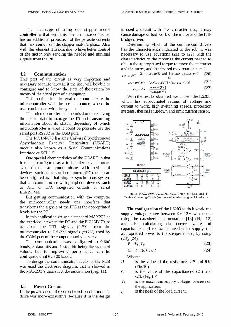
Fig.11. MAX220/MAX232/MAX232A Pin Configuration and
Typical Operating Circuit (courtesy of Maxim Integrated Products).
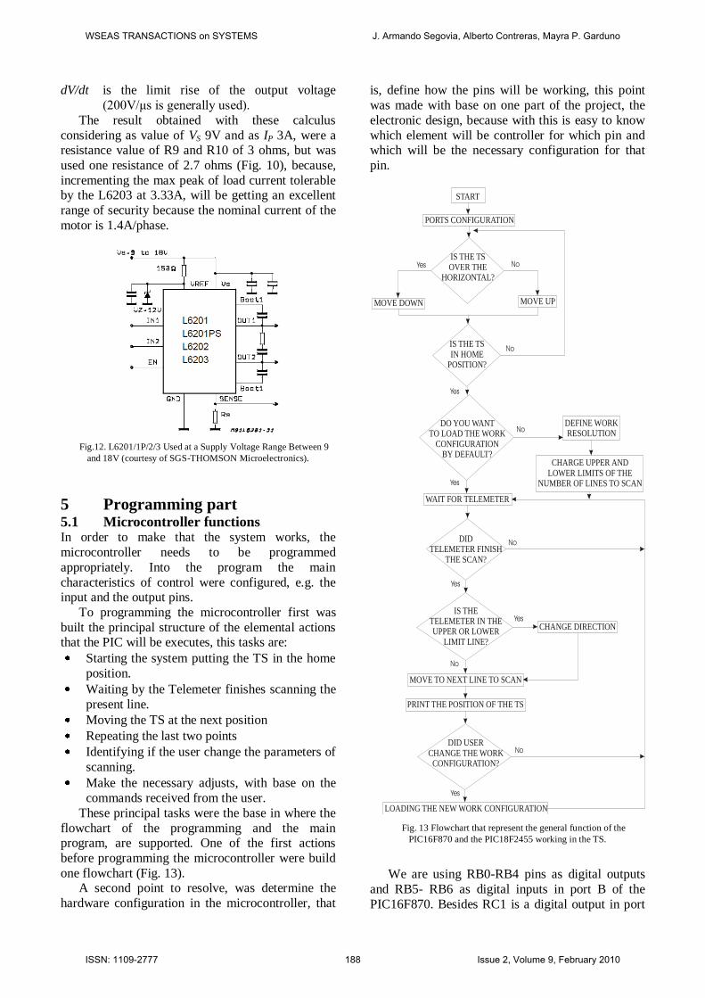
The configuration of the L6203 to do it work at a supply voltage range between 9V-12V was made
using the datasheet documentation [18] (Fig. 12)
and also calculating the correct values of
capacitance and resistance needed to supply the appropriated power to the stepper motor, by using
(23), (24).
pS IVR (23)
)/( dtdVIC p (24)
Where: R is the value of the resistances R9 and R10
(Fig.10)
C is the value of the capacitances C15 and C16 (Fig.10)
VS is the maximum supply voltage foreseen on
the application. Ip is the peak of the load current.
WSEAS TRANSACTIONS on SYSTEMS J. Armando Segovia, Alberto Contreras, Mayra P. Garduno
ISSN: 1109-2777 187 Issue 2, Volume 9, February 2010
dV/dt is the limit rise of the output voltage
(200V/μs is generally used).
The result obtained with these calculus
considering as value of VS 9V and as IP 3A, were a resistance value of R9 and R10 of 3 ohms, but was
used one resistance of 2.7 ohms (Fig. 10), because,
incrementing the max peak of load current tolerable by the L6203 at 3.33A, will be getting an excellent
range of security because the nominal current of the
motor is 1.4A/phase.
Fig.12. L6201/1P/2/3 Used at a Supply Voltage Range Between 9
and 18V (courtesy of SGS-THOMSON Microelectronics).
5 Programming part 5.1 Microcontroller functions In order to make that the system works, the
microcontroller needs to be programmed
appropriately. Into the program the main
characteristics of control were configured, e.g. the input and the output pins.
To programming the microcontroller first was
built the principal structure of the elemental actions that the PIC will be executes, this tasks are:
Starting the system putting the TS in the home
position.
Waiting by the Telemeter finishes scanning the
present line.
Moving the TS at the next position
Repeating the last two points
Identifying if the user change the parameters of
scanning.
Make the necessary adjusts, with base on the
commands received from the user.
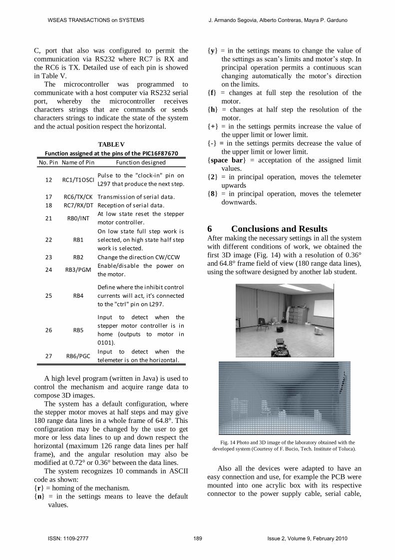
These principal tasks were the base in where the
flowchart of the programming and the main program, are supported. One of the first actions
before programming the microcontroller were build
one flowchart (Fig. 13). A second point to resolve, was determine the
hardware configuration in the microcontroller, that
is, define how the pins will be working, this point
was made with base on one part of the project, the
electronic design, because with this is easy to know
which element will be controller for which pin and which will be the necessary configuration for that
pin.
Fig. 13 Flowchart that represent the general function of the
PIC16F870 and the PIC18F2455 working in the TS.
We are using RB0-RB4 pins as digital outputs
and RB5- RB6 as digital inputs in port B of the
PIC16F870. Besides RC1 is a digital output in port
START
PORTS CONFIGURATION
IS THE TS IN HOME
POSITION?
IS THE TS OVER THE
HORIZONTAL?
MOVE DOWN MOVE UP
DO YOU WANT TO LOAD THE WORK
CONFIGURATION BY DEFAULT?
DEFINE WORK RESOLUTION
CHARGE UPPER AND LOWER LIMITS OF THE
NUMBER OF LINES TO SCAN
WAIT FOR TELEMETER
DID TELEMETER FINISH
THE SCAN?
IS THE TELEMETER IN THE UPPER OR LOWER
LIMIT LINE?
CHANGE DIRECTION
MOVE TO NEXT LINE TO SCAN
DID USER CHANGE THE WORK
CONFIGURATION?
LOADING THE NEW WORK CONFIGURATION
Yes No
No
Yes
Yes
No
Yes
No
No
No
Yes
Yes
PRINT THE POSITION OF THE TS
WSEAS TRANSACTIONS on SYSTEMS J. Armando Segovia, Alberto Contreras, Mayra P. Garduno
ISSN: 1109-2777 188 Issue 2, Volume 9, February 2010
C, port that also was configured to permit the
communication via RS232 where RC7 is RX and
the RC6 is TX. Detailed use of each pin is showed
in Table V. The microcontroller was programmed to
communicate with a host computer via RS232 serial
port, whereby the microcontroller receives characters strings that are commands or sends
characters strings to indicate the state of the system
and the actual position respect the horizontal.
A high level program (written in Java) is used to
control the mechanism and acquire range data to
compose 3D images.
The system has a default configuration, where the stepper motor moves at half steps and may give
180 range data lines in a whole frame of 64.8°. This
configuration may be changed by the user to get more or less data lines to up and down respect the
horizontal (maximum 126 range data lines per half
frame), and the angular resolution may also be modified at 0.72° or 0.36° between the data lines.
The system recognizes 10 commands in ASCII
code as shown:
{r} = homing of the mechanism. {n} = in the settings means to leave the default
values.
{y} = in the settings means to change the value of
the settings as scan’s limits and motor’s step. In
principal operation permits a continuous scan
changing automatically the motor’s direction on the limits.
{f} = changes at full step the resolution of the
motor. {h} = changes at half step the resolution of the
motor.
{+} = in the settings permits increase the value of the upper limit or lower limit.
{-} = in the settings permits decrease the value of
the upper limit or lower limit.
{space bar} = acceptation of the assigned limit values.
{2} = in principal operation, moves the telemeter
upwards {8} = in principal operation, moves the telemeter
downwards.
6 Conclusions and Results After making the necessary settings in all the system
with different conditions of work, we obtained the
first 3D image (Fig. 14) with a resolution of 0.36° and 64.8° frame field of view (180 range data lines),
using the software designed by another lab student.
Fig. 14 Photo and 3D image of the laboratory obtained with the
developed system (Courtesy of F. Bucio, Tech. Institute of Toluca).
Also all the devices were adapted to have an
easy connection and use, for example the PCB were
mounted into one acrylic box with its respective connector to the power supply cable, serial cable,
No. Pin Name of Pin Function designed
12 RC1/T1OSCIPulse to the "clock-in" pin on
L297 that produce the next step.
17 RC6/TX/CK Transmission of serial data.
18 RC7/RX/DT Reception of serial data.
21 RB0/INTAt low state reset the stepper
motor controller.
22 RB1
On low state full step work is
selected, on high state half step
work is selected.
23 RB2 Change the direction CW/CCW
24 RB3/PGMEnable/disable the power on
the motor.
25 RB4
Define where the inhibit control
currents will act, it's connected
to the "ctrl" pin on L297.
26 RB5
Input to detect when the
stepper motor controller is in
home (outputs to motor in
0101).
27 RB6/PGCInput to detect when the
telemeter is on the horizontal.
TABLE V
Function assigned at the pins of the PIC16F87670
WSEAS TRANSACTIONS on SYSTEMS J. Armando Segovia, Alberto Contreras, Mayra P. Garduno
ISSN: 1109-2777 189 Issue 2, Volume 9, February 2010

and the motor cable, all with the objective to do one
handy device.
Moreover the interface of the control was
designed to be used with the most common software or with most of the software developed to acquire
3D images, sending different messages that indicate
the command that is needed to continue working and the state of the system, for example when the
TS is putted on one new line, the microcontroller
sends one message with the format (Fig. 15):
Fig. 15. Message of position sent by the microcontroller; the sign
indicate if the TS is over (+) or under (-) the horizontal; the position
indicate the present position of the TS; the direction indicates the
present direction in which the TS is moved up or down (U/D).
The maximum speed obtained in the scan of a
whole frame was around 4.8 minutes, this speed could be enhanced making an exactly coordination
of the system between the telemeter, microcontroller
and host computer, processing the data image with an efficient method, but even so the max speed only
could be not less than 7s per frame scan with 252
range data lines, because the telemeter and the microcontroller need at least 13ms to scan a line and
0.5ms to move the telemeter to the next position,
respectively. Besides, the necessary time to let the
computer process input data coming from the TS and the LMS200 must be equal to the time required
by them.
Home position is detected by means of the use of a microswitch; this method could be improved using
an optical sensor or an inclinometer.
The current position of the mechanism is determined by means of the number of steps
realized from the home position; to improve this
information an absolute optical sensor could be
used. The TS can move up to 150 degrees/seg but the
transmission of data from the LMS200 limits this
operation, thus, at a speed of transmission of 9,600 bauds, working frequency by default of the
LMS200. Working in this way, an image is obtained
every 4,8 minutes. The LMS200 allows maximum
speed transference 38,600 bauds, which would reduce transference time to a quarter of the current
time. Additionally, the change to a strategy of type
pipeline would allow improving this performance still more.
To finish this work, at the present the whole
system which is mounted on the Pioneer 3-AT
mobile robot (Fig. 16) is working fine and it is being
used to make different tests to develop one new and better version of the software to acquire depth
images of the robot’s environment.
Fig. 16 In the left the PCB designed to control the TS and in the right
the TS mounted on the Pionner 3AT mobile robot.
Acknowlegments: This work was supported mainly by the
CONACyT (Mexico) under the agreement CO-028,
and in part by the National Institute of Nuclear Research (ININ) and the Technological Institute of
Toluca.
References:
[1] Kay Boehnke, Fast Object Localization With
Real Time 3D Laser Range Sensor Simulation, WSEAS TRANSACTIONS on
ELECTRONICS, Issue 3, Volume 5, March
2008, ISSN: 1109-9445. [2] Hartmut Surmann, Kai Lingemann, Andreas
N¨uchter and Joachim Hertzberg, A 3D laser
range finder for autonomous mobile robots, Proceedings of the 32
nd ISR (International
Symposium on Robotics), pp. 153 - 158, 19-21
April 2001.
[3] Zhiyu Xiang and Wenhui Zhou, 3D Map Building for Mobile Robots Using a 3D Laser
Range Finder, D.-S. Huang, K. Li, and G.W.
Irwin (Eds.): ICIC 2006, LNCIS 345, pp. 785 – 790, 2006. © Springer-Verlag Berlin
Heidelberg 2006.
[4] I Jivet, A Brindusescu, and I Bogdanov, A
Perception Oriented Formal Model for 3D Sensor Depth Images, 12th WSEAS
International Conference on SYSTEMS,
Heraklion, Greece, July 22-24, 2008, ISBN: 978-960-6766-83-1, ISSN: 1790-2769.
[5] Marius Otesteanu and Vasile Gui, 3D Image
Sensors, an Overview, WSEAS TRANSACTIONS on ELECTRONICS, Issue
3, Volume 5, March 2008, ISSN: 1109-9445.
POS: xxxxXSign
Position
Direction
WSEAS TRANSACTIONS on SYSTEMS J. Armando Segovia, Alberto Contreras, Mayra P. Garduno
ISSN: 1109-2777 190 Issue 2, Volume 9, February 2010
[6] SICK Technical Description Laser
Measurement Systems LMS200 to LMS291, ©
SICK AG · Division Auto Ident · Germany ·
All rights reserved 8008970/QI72/2006-12. [7] https://www.mysick.com/eCat.aspx?go=Finder
&Cat=Row&At=Fa&Cult=English&Category=
Produktfinder. [8] R. C. Hibbeler, Engineering Mechanics Statics,
10th ed., Mexico, published by Pearson
Education, Inc., publishing as PRENTICE HALL, INC., 2004 pp. 437–490.
[9] Theodore Baumeister, Eugene A. Avallone,
Theodore Baumeister III, Marks’ Standard
Handbook for Mechanical Engineers, 8th ed., Ed. U.S.A. McGraw-Hill, 1978, Chapter 1 and
3.
[10] Ferdinand P. Beer, E. Russell Johnston, Jr., Vector Mechanics for Engineers: Dynamics,
2th ed., Ed. Mexico: McGraw-Hill Inc., 1972.
[11] R. C. Hibbeler, Engineering Mechanics Dynamics 10th ed., Mexico, published by
Pearson Education, Inc., publishing as
PRENTICE HALL, INC., 2004.
[12] Fernando E. Valdes Perez, Ramon Pallas Areny, Microcontrollers: Foundations and
applications with PIC”, 1st ed., Ed. Alfaomega,
2007 Mexico. [13] Gilberto Mercado Lopez, Design and
Construction of robots, published by Control
Robotics and Automation (CRYA).
[14] H. Sax, Steeper motor driving - application
note, published by SGS Thomson
Microelectronics, 1995.
[15] Microchip, PIC16F870/871 Data Sheet 28/40-Pin, 8-Bit CMOS FLASH
Microcontrollers, DS30569B, ©2003
Microchip Technology Inc. [16] Microchip, PIC18F2455/2550/4455/4550
Data Sheet 28/40/44-Pin, High Performance,
Enhanced Flash, USB Microcontrollers with nanoWatt Technology, DS39632D, © 2007
Microchip Technology Inc.
[17] Datasheet L297-L297D, Stepper motor
controller, published by SGS Thomson Microelectronics, 1996.
[18] Datasheet L6201, L6202 - L6203 DMOS full
bridge drive, published by SGS Thomson Microelectronics, 1997.
[19] I. Jivet, A. Brindusescu, Real Time
Representation of 3D Sensor Depth Images, WSEAS TRANSACTIONS on
ELECTRONICS, Issue 3, Volume 5, March
2008, ISSN: 1109-9445.
[20] C. H. Jensen, Engineering Drawing and Design, 1st ed., Ed. U.S.A., McGraw-Hill Inc.,
1968.
[21] Hamilton H. Mabie, Charles F. Reinholtz, Mechanisms and Dynamics of Machinery 2th
ed., Ed Limusa, 2004, Mexico.
WSEAS TRANSACTIONS on SYSTEMS J. Armando Segovia, Alberto Contreras, Mayra P. Garduno
ISSN: 1109-2777 191 Issue 2, Volume 9, February 2010