mechanical couplings & alignment
TRANSCRIPT

MECHANICAL COUPLINGS &
ALIGNMENT (MCA)
Learner Guide

TABLE OF CONTENTS
GENERAL INSTRUCTIONS PAGE 1 HOW TO USE THIS PACKAGE PAGE 2 PROGRAMME NO. 1 MCA-1 OBJECTIVE PAGE 3 TASK NO. 1: INSTRUCTIONS PAGE 4 RESOURCE NOTES PAGE 5 SELF TEST EXERCISE PAGE 12 TASK NO. 2: INSTRUCTIONS PAGE 14 RESOURCE NOTES PAGE 15 SELF TEST EXERCISE PAGE 17 PROGRAMME NO. 2 MCA-2 OBJECTIVE PAGE 19 TASK NO. 1: INSTRUCTIONS PAGE 20 RESOURCE NOTES PAGE 21 SELF TEST EXERCISE PAGE 23 CRITERION CHECK LIST PAGE 24 TASK NO. 2: INSTRUCTIONS PAGE 25 RESOURCE NOTES PAGE 26 SELF TEST EXERCISE PAGE 29 CRITERION CHECK LIST PAGE 30 TASK NO. 3: INSTRUCTIONS PAGE 31 RESOURCE NOTES PAGE 32 SELF TEST EXERCISE PAGE 34 CRITERION CHECK LIST PAGE 35 TASK NO. 4: INSTRUCTIONS PAGE 36 RESOURCE NOTES PAGE 37 SELF TEST EXERCISE PAGE 41 CRITERION CHECK LIST PAGE 42 PROGRAMME NO. 3 MCA-3 OBJECTIVE PAGE 43 TASK NO. 1: INSTRUCTIONS PAGE 44 RESOURCE NOTES PAGE 45 SELF TEST EXERCISE PAGE 47 CRITERION CHECK LIST PAGE 48 TASK NO. 2: INSTRUCTIONS PAGE 49 RESOURCE NOTES PAGE 50 SELF TEST EXERCISE PAGE 53 CRITERION CHECK LIST PAGE 54 TASK NO. 3: INSTRUCTIONS PAGE 55 RESOURCE NOTES PAGE 56 SELF TEST EXERCISE PAGE 61 CRITERION CHECK LIST PAGE 62

PROGRAMME NO. 4 MCA-4 OBJECTIVE PAGE 63 TASK NO. 1: INSTRUCTIONS PAGE 64 RESOURCE NOTES PAGE 65 SELF TEST EXERCISE PAGE 69 CRITERION CHECK LIST PAGE 70
CONTACT DETAILS: https://techav.co.za

Back to Table of Contents 1
MECHANICAL COUPLINGS & ALIGNMENT (MCA.)
GENERAL INSTRUCTIONS This series of programmes has been designed to afford you the opportunity to learn the basics of a very important industrial subject, namely that of machine alignment. The package consists of (4) programmes, each with its own video programme. Video programmes describe and demonstrate important facts and procedures that the plant fitter needs to know. The workbook (this book) contains:
o Resource notes, which complement each video plus provide extra information. o Exercises and self-evaluation tests.
The workbook is an integral part of your training and must be used in conjunction with the video programmes and your instructor / supervisor or Course Controller. It is strongly recommended that you begin with the FIRST programme (MCA-1) especially if you have no knowledge of the subject.

Back to Table of Contents 2
HOW TO USE THIS TRAINING PACKAGE Please read this page carefully before continuing. INSTRUCTIONS FOR LEARNING Step (1) Read the objectives stated at the beginning of each task. Step (2) Read the self test exercise which follows the resource notes. N.B: If you can answer all the questions then you don't need instruction. Ask your instructor to allow you to perform the CRITERION TEST for the programmes in question. Step (3) Read the resource notes for the programme you are involved in. Step (4) View the video for the programme, following any verbal or on-screen instructions. N.B: You will see either "DISCUSSION" or "PRACTICAL" signs, accompanied by music during the video programmes. At such times switch off the video (i.e. STOP THE VIDEO) and check the instructions in the workbook under TASK heading. Step (5) At the conclusion of the video, stop the video. Step (6) Perform the CRITERION TEST for the programme or, if you wish, perform more practical exercises to gain experience and then perform the CRITERION TEST. N.B: Ask your instructor for the necessary criterion test instruction and materials etc.

Back to Table of Contents 3
PROGRAMME NO. 1 MCA-1 AN OVERVIEW OF MECHANICAL COUPLINGS
AND ALIGNMENT PRINCIPLES OBJECTIVE At the end of this programme you will be able to do the following:
o Identify commonly used linear couplings. o Describe the basic principles and concepts of linear machinery alignment. o Effect the necessary preparations for alignment.
AIM OF PROGRAMME This programme has been designed to offer the newcomer (e.g. apprentice, learner technician etc.) valuable basic information in the form of facts which should always be kept in mind when performing an alignment job. Knowledge and understanding of these facts will make the task of machine alignment more interesting, meaningful and, most of all, save you or your company precious time and money.
TURN THE PAGE FOR TASK NO. 1 INSTRUCTIONS.

Back to Table of Contents 4
TASK NO. 1 - MCA-1 AN OVERVIEW
INSTRUCTIONS
o Read the resource notes beginning on the next page. o Obtain the video MCA-1. o Watch the video through to the end. o Now play the video through to the first "DISCUSSION" break (you will see the word
"discussion" on screen and hear music). o Stop the video at this point and attempt the first exercise in the workbook, following
the resource notes. o Have your Instructor check your work. o Proceed with the video viewing. o Continue until you see the next "discussion" break and again perform the suggested
exercise or self test. o Continue until end of video. o Perform the Criterion Test which will be given to you by your Instructor or Course
Controller.
TURN PAGE FOR TASK NO. 1 - RESOURCE NOTES.

Back to Table of Contents 5
RESOURCE NOTES TASK NO. 1 MCA-1
AN OVERVIEW OF MECHANICAL COUPLINGS AND ALIGNMENT PRINCIPLES
A mechanical coupling is a device employed to connect two shafts, end to end. The coupling itself has to be capable of transmitting the rated torque capacity of the shaft and at the same time accommodate any misalignment between the shafts. Over the years, through trial and error and by design, many coupling types have been developed. This overview attempts to describe some of the most popularly encountered types, which can be loosely classified as: (a) "Rigid Couplings" and (b) The so-called "Flexible" couplings. RIGID COUPLINGS Although the simplest and cheapest form of coupling, rigid types demand "perfection" in their alignment with the mating shafts. Any misalignment would result in undue forces and rapid wear of bearings, casings and the coupling itself. A simple form of rigid coupling is the "flange-faced" type (see Figure No. 1).
Fig. 1
Another form of solid coupling is the Ribbed type (see Figure No.2). In this type a key locks the two shafts. Each shaft has a key-way machined at its end. The key is held by a two piece coupler housing which is then bolted together in position.
Fig. 2

Back to Table of Contents 6
FLEXIBLE COUPLINGS So called because such couplings allow for an amount of misalignment, albeit only a very small amount. Flexible couplings are by far the most commonly encountered and for purposes of recognition we illustrate many types below.
Fig. 3 Gear Type Coupling Fig. 4 Steel-Grid Type Coupling ("Bibby" Coupling)
Fig. 5 Flexible Disc Type Fig. 6 Flexible Link Type
Fig. 7 Roller-Chain Types Fig. 8 Sliding Block Type
Fig. 9 Sliding Disc Type

Back to Table of Contents 7
The "flexible-couplings" so far illustrated are normally steel constructed, however another group of "flexible-couplings" utilise rubber, plastic or neoprene impregnated fibre or other "soft" material to serve as a compressive cushion between the metal elements connecting the shafts. Such couplings are described generally as "Elastomeric-Flex" couplings. Common types of Elastomeric Couplings are illustrated hereunder.
Fig. 10 Compression Coupling Fig. 11 Rubber Block Coupling (Spider)
Fig. 12 Flexible Sleeve Coupling Fig. 13 Shear Type Coupling (Rubber Type) So far we have illustrated some common types and designs of shaft or mechanical couplings. There obviously are other types, styles and designs, but virtually all work on similar principles. The need for so many types evolved from industrial demands for such considerations as: 1. Cost. 2. Speeds and shafts. 3. Power transmitted. 4. Loads encountered. 5. Ease of maintenance. 6. Quiet operation. … and other considerations. For a more detailed explanation of couplings we suggest you study the various coupling manufacturers' catalogues and service bulletins as it would be impossible to detail every type in this programme.

Back to Table of Contents 8
What is certainly important is that you understand the principles about connecting two rotating machines together via their shafts. We generally refer to this feat as "alignment", so let's spend some time in this subject, because much of your time spent on plant or equipment maintenance will be spent on such tasks. THE PRINCIPLES OF ALIGNMENT As a general rule most plant operating equipment is run, or powered, by an electric or diesel motor. For purposes of maintenance it is convenient to be able to separate the motor from the equipment being driven. Several methods are used to "connect" a motor to a piece of machinery (e.g. V-belts, roller-chains, gears or in-line couplings). This programme deals only with "in-line" or "linear" couplings, whereby two shafts are connected on their common axis. In an ideal or perfect situation two units coupled together at their shafts would be absolutely coincident, meaning that the two shafts would lie perfectly upon a common centre, whether rotating or at rest. This situation seldom occurs in practice. There are many reasons why; some obvious, others less obvious. Draughtsmen and engineers strive for the "perfect-alignment" situation, but so far it has been an impossible dream. Why is this? Well, for instance, as you know, a shaft is supported by a pair of bearings. Bearings must have a certain amount of "clearance" otherwise no rolling action could occur. As bearing clearances vary slightly, there will be a certain amount of "free-play" either up and down (radial) or in and out (axial) at the shaft end. Further, machinery is usually mounted upon a concrete base, or at least the metal - plate is secured into concrete. "Settling" of the base is commonly encountered whereby slight movement causes one machine to move "off-line" with the other. We are not talking large amounts, but a 1 mm movement of the bed plate can impose an angular deflection of shaft centres of several degrees. Let's study these concepts in diagram form.
Fig. 14
Perfect alignment exists only when shaft centres are absolutely coincident, at rest and rotating. Any deviation from the coincident centre line is considered as miss.-alignment. Certain tolerances of miss-alignment are "allowed" and these are usually evident and measured at the coupling area.
Back to Table of Contents 9
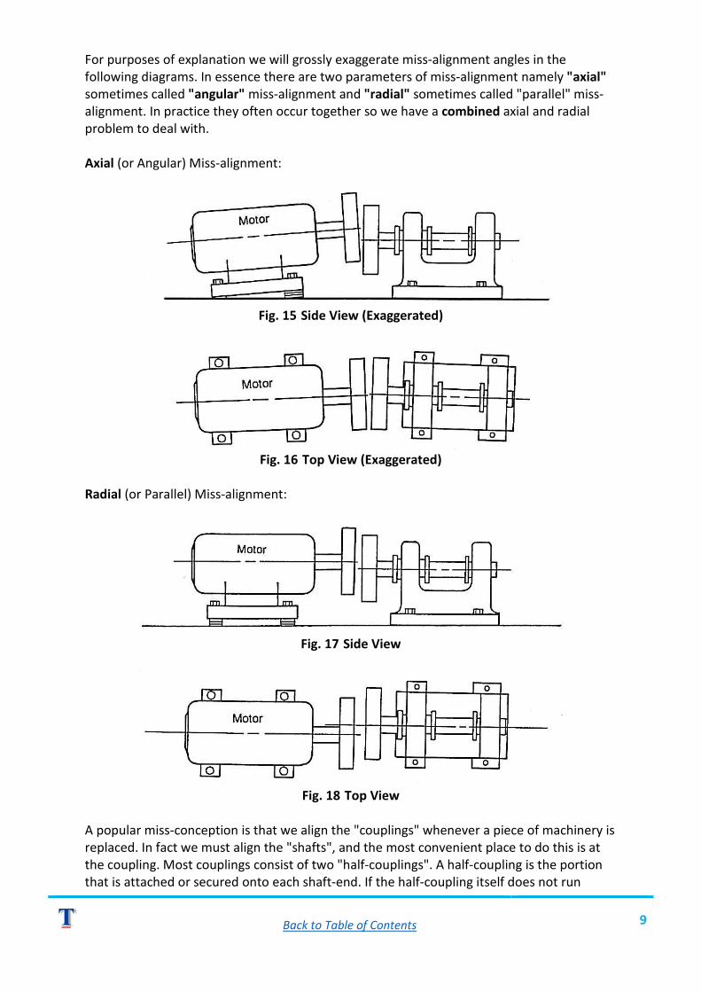
For purposes of explanation we will grossly exaggerate miss-alignment angles in the following diagrams. In essence there are two parameters of miss-alignment namely "axial" sometimes called "angular" miss-alignment and "radial" sometimes called "parallel" miss-alignment. In practice they often occur together so we have a combined axial and radial problem to deal with. Axial (or Angular) Miss-alignment:
Fig. 15 Side View (Exaggerated)
Fig. 16 Top View (Exaggerated)
Radial (or Parallel) Miss-alignment:
Fig. 17 Side View
Fig. 18 Top View
A popular miss-conception is that we align the "couplings" whenever a piece of machinery is replaced. In fact we must align the "shafts", and the most convenient place to do this is at the coupling. Most couplings consist of two "half-couplings". A half-coupling is the portion that is attached or secured onto each shaft-end. If the half-coupling itself does not run

Back to Table of Contents 10
"concentric" to the shaft then the combination will be miss-aligned no matter how well the two half-couplings are "aligned". See diagram for visual explanation.
Fig. 19
Before any alignment correction is attempted, it is important that: (a) The machine's shafts are checked for run-out. (b) The half couplings run true to the shaft. The above checks should be made using a dial-test-indicator (clock-gauge).
Fig. 20
NB: The necessary corrections should be effected prior to attempting to correct alignment. Ideally when two machines are brought together (Le. a motor and the driven unit) the two half-couplings should be in alignment both axially and radially. It is seldom (if ever) that two half-couplings actually contact each other during installation. A gap exists between the couplings to either allow for thermal expansion (shaft growth) of the shafts or to accommodate end floats. A specified gap is recommended by the design engineers which must be adhered to. Do not expect a "flexible-coupling" to compensate for fitting errors. The term "flexible" implies that the coupling can "bend" or "twist", which of course it can. But the bending or twisting action occurs owing to operating conditions, not by careless fitting. Flexible couplings must still be carefully aligned according to set specifications.

Back to Table of Contents 11
The results of careless or faulty alignment are: o Rapid bearing failure. o Machine vibration. o Wear in the coupling itself. o Shaft fatigue.
All of which result in costly breakdowns and of course much more sweat and toil for the plant fitter! SAFETY As this is supposed to be a practical course of instructions we would not be doing our job if we didn't spell out the latent dangers that can occur when you are working on rotating machinery. The following "safety-rules" should be adhered to in all cases of maintenance, but especially when attending to couplings. THE RULES (to keep you alive and well) 1. Never work on a machine that has not been isolated and safety tagged at the main control unit. 2. Never remove a safety guard until the machine is stationary. 3. Always use the correct lifting equipment to raise or lower heavy machines. 4. Keep the work area clean and tidy to prevent you from tripping, slipping or damaging equipment. 5. Clean up any oil or liquid spillage to prevent slipping or, if applicable, to reduce a fire hazard. 6. Don't use petrol or flammable liquids to clean parts - especially electric motor parts. 7. Ensure that all tools or equipment are removed from coupling area before the machines are re-connected to the power supply. 8. Replace safety guards or covers before running the machinery. 9. Notify your Supervisor in the event of any malfunction (e.g. machine fault, fire or personal injury). 10. Exercise common sense -we all have some somewhere!
NOW WATCH THE VIDEO. TURN PAGE FOR SELF-CHECK EXERCISE.

Back to Table of Contents 12
TASK NO. 1 - MCA-1 SELF TEST EXERCISE
Answer the following questions, then check your answers against the Resource Notes.
1. Name two types of rigid couplings. i)_______________________________________________________ (ii)______________________________________________________ 2. What does an Elastomeric coupling contain that others do not? ________________________________________________________ 3. What would the term "Perfect Alignment" suggest? ________________________________________________________ 4. What two factors can disturb alignment? i)_______________________________________________________ (ii)______________________________________________________ 5. What two "parameters" of miss-alignment have been mentioned so far? i)_______________________________________________________ (ii)______________________________________________________ 6. What is a "half-coupling"? ________________________________________________________ 7. What two things must first be checked before any alignment correction is attempted? i)_______________________________________________________ (ii)______________________________________________________ 8. Why does a small gap exist between half-couplings? ________________________________________________________ 9. Careless fitting or faulty alignment will result in what? Give four conclusions. i)_______________________________________________________ (ii)______________________________________________________ iii)______________________________________________________ (iv)_____________________________________________________
YES
NO

Back to Table of Contents 13
10. List the 10 safety rules mentioned (give short answers). 1. __________________________________________________ 2. __________________________________________________ 3. __________________________________________________ 4. __________________________________________________ 5. __________________________________________________ 6. __________________________________________________ 7. __________________________________________________ 8. __________________________________________________ 9. __________________________________________________ 10. __________________________________________________ TOTAL CORRECT
(CHECK YOUR RESPONSES BY READING THE NOTES OR REPLAYING THE VIDEO.) PROCEED TO TASK NO. 2.
YES
NO

Back to Table of Contents 14
TASK NO. 2 - MCA-2 PREPARATION FOR ALIGNMENT
INSTRUCTIONS
o Read the resource notes before viewing the video portion. o Proceed as you did in Task No. 1 and end by doing the self test and suggested
exercises. o Ask your Instructor for the Criterion Test to conclude this programme.

Back to Table of Contents 15
RESOURCE NOTES TASK NO. 2 MCA-1
PREPARATION FOR ALIGNMENT Whenever machinery has been disconnected from its coupling for maintenance or other reasons it follows, that upon re-installing, we will have to re-align the units. No matter what coupling type is encountered, certain conditions have to be met prior to actually getting down to aligning the coupling. Before we touch on specifics, let's overview some general rules for machinery installation. INSTALLATION PRACTICE 1. The driven unit is always installed first, the motor (Le. the driving unit) is then aligned to the driven unit's shaft. 2. A "solid-base" must be obtained on both driven unit and the motor. This that all mounting feet (pedestals), the base plate mounting pads etc., must be flat and there must be zero "rocking". 3. Ensure that motor adjusting bolts, (jacking bolts) are in good order and that the motor is able to be moved. Utilise proper lifting apparatus as and when necessary. 4. Mount units using zero shims. DETERMINING MOTOR ROCK 1. Use a 0,05 mm feeler gauge to check if any gap exists under motor feet - (N.B: Motor is resting on its own - bolts not tightened). 2. If any foot is not resting / touching base plate then measure (with a feeler gauge) the gap that exists. 3. Obtain or make a shim of corresponding thickness and insert under the foot. Ensure that shim is slightly larger than the foot (allow ± 1 mm excess).
Fig. 21
Once you have established a "solid base" then alignment procedures can begin. The actual procedures will vary according to coupling types. We will cover various procedures in programmes 2 and onward. This then concludes programme one.


Back to Table of Contents 17
TASK NO. 2 - MCA-1 SELF TEST EXERCISE
This is a practical exercise to be done on a training model in your training centre workshop. INSTRUCTIONS Ask your Instructor for a working model to use and do the following: 1. Set up the driven unit and motor onto the base as described in the video. 2. Cut and insert the necessary shims to eliminate motor rock. 3. Tighten down the base bolts ensuring you leave a ± 3 mm gap between coupling halves.
CHECK YOUR WORK AGAINST THE CHECKLIST ON NEXT PAGE.

Back to Table of Contents 18
SELF CHECK
o Was "driven" unit installed and secured first?
o Is the motor resting on packs of shims?
o Has a "solid-motor-base" been obtained?
o Are shims made to foot size or slightly larger?
o Does a ± 3 mm gap exist between the half-couplings?
ONCE YOU HAVE COMPLETED THIS TASK, THEN HAVE YOUR INSTRUCTOR CHECK YOUR WORK.
YES
NO

Back to Table of Contents 19
PROGRAMME NO. 2 MCA-2 "BIBBY" COUPLINGS
OBJECTIVE At the end of this programme you will be able to:
o Identify. o Dismantle. o Inspect. o Re-assemble. o Align.
A typical "Bibby" or "Steel Grid Coupling". AIM OF THIS PROGRAMME This programme has been produced to offer you a visual and written explanation for performing typical routine maintenance tasks on a Bibby type coupling.

Back to Table of Contents 20
TASK NO. 1 - MCA-2 COMPONENT PARTS "BIBBY" COUPLINGS
INSTRUCTIONS
o Read the Resource notes beginning over page. o Obtain video No. MCA-2. o Watch the video up to the first "Practical" time break. o Stop the video and do the self test which appears after the Resource notes. o Continue on to Task No. 2, once you have completed Task No. 1.

Back to Table of Contents 21
RESOURCE NOTES TASK NO. 1 MCA-2
"BIBBY" COUPLING DISMANTLE, CLEAN, INSPECT AND ASSEMBLE The so-called "Bibby" Coupling is more correctly referred to as a "Grid" Coupling. Several designs are manufactured but the primary construction is similar in each. Two of the commonest types are illustrated below:
Fig. 23 Vertical Shroud Fig. 24 Horizontal Shroud In effect the coupling consists of "ribbed" or "slotted" half-couplings. A steel spring or grid is employed to connect the half-couplings. The spring may be one full segment or in several segments. The sectional shape of the spring is such that it occupies the full depth of the half-coupling slots. A two piece "shroud" envelopes the coupling serving to retain lubricant, usually grease, and to seal out dirt arid dust. Oil seals, usually 'O' rings, are provided for positive dirt exclusion. A gasket may be employed between the two shroud contact faces.
Fig. 25 GENERAL MAINTENANCE PROCEDURES
o Grid couplings are normally lubricated on a weekly basis via the grease nipple.

Back to Table of Contents 22
o Only clean, water-free grease should be used. o Every 12 months the couplings should be dismantled, cleaned, inspected and re-
assembled using new parts as necessary. DISMANTLE (PROCEDURE) 1. Ensure plant is isolated and tagged. 2. Remove safety guard and place it out of harm's way. 3. Remove shroud bolts, nuts and washers. Store them to prevent loss. 4. Carefully move shrouds and slide them out of the way. Ensure that you do not damage the oil seals during this process. 5. Carefully prise spring out of coupling slots. N.B: Do not apply. force onto spring that might damage the slots, spring or couplings. In other words, avoid digging the springs out with a chisel etc. and do not use a hammer on the coupling. WASH AND INSPECT 1. Using a suitable degreasing agent (not a flammable liquid) clean all parts. An old stiff paintbrush is ideal to clean out the slots in half-couplings. 2. Inspect all parts for any damage or wear. 3. Insert spring (now clean) into the slots and check if it fits neatly without "play" which would indicate worn slots or springs (or both). 4. Inspect the seals and gasket for damage and wear. 5. Inspect the shroud covers for any damage. 6. Inspect the fasteners (bolts, nuts and washers) and renew them if they are in anyway damaged or worn. ASSEMBLE COUPLING At this stage it is assumed that alignment has not been disturbed. Normally alignment would be checked and set before assembly. This procedure (alignment) begins in Task No. 2 of this programme. ASSEMBLY PROCEDURE 1. Insert spring or segments into coupling, without force. 2. Pack around spring the recommended type of grease. 3. Slide shrouds together, carefully, to cover the coupling, then fit two bolts (opposites) - finger-tight only. N.B: Care must be taken to avoid damaging '0' ring seals when shrouds are moved. 4. Fit all other shroud bolts/nuts then tighten them up evenly in a cross-star pattern to avoid distortion. 5. Wipe off surplus grease and then replace the safety guard. 6. Inform your Supervisor that job is done, in order to effect electrical connections.
NOW WATCH THE VIDEO DEMONSTRATION. TURN PAGE FOR SELF CHECK EVALUATION.

Back to Table of Contents 23
SELF CHECK EXERCISE & EVALUATION TASK NO. 1 - MCA-2
INSTRUCTIONS
o Ask your instructor / supervisor to allocate you a Bibby coupling unit (or training simulator).
o Perform a full maintenance service on the coupling as you learned in Task No. 1 Resource notes and video programme.
o Have your instructor check your work before fitting safety covers. o Evaluate your work using the criterion check list on the next page.
TURN PAGE FOR CRITERION CHECK LIST.

Back to Table of Contents 24
CRITERION CHECK LIST TASK NO. 1 MCA-2
Tick the correct response, YES or NO.
1. Was the equipment electrically isolated according to company rules? 2. All parts were properly stored after removal. 3. Non-flammable cleaning fluid used. 4. All parts inspected for damage or wear. 5. List below all part names and condition Part Condition. Part Condition ___________________ __________________________________________ ___________________ __________________________________________ ___________________ __________________________________________ ___________________ __________________________________________ ___________________ __________________________________________ ___________________ __________________________________________ ___________________ __________________________________________ 6. Spring inserted correctly without force. 7. Shrouds installed correctly without seal damage. 8. Correct grease used to pack coupling. 9. Fasteners tightened securely and evenly. 10. Supervisor / lnstructor checked your work.
IF YOUR SUPERVISOR / INSTRUCTOR HAS CHECKED YOUR WORK AND CONFIRMED THAT IT IS OF CORRECT STANDARD,
THEN PROCEED TO TASK NO. 2 OVER PAGE.
YES
NO

Back to Table of Contents 25
TASK NO. 2 - MCA-2 AXIAL CORRECTION OF BIBBY COUPLING
INSTRUCTIONS
o Read the Resource notes beginning over page. o Then play video from where you last stopped at the "practical logo". o Stop video at next Practical logo (i.e. at the end of Axial alignment). o Do the practical exercise for Task No. 2.
NB: Remember that you can, if you wish, play the video more than once in order to fully understand how to do the job.
TURN PAGE FOR RESOURCE NOTES.

Back to Table of Contents 26
RESOURCE NOTES TASK NO. 2 MCA-2
BIBBY COUPLING -AXIAL ALIGNMENT (TOP AND BOTTOM) NOTE: The procedures shown are typical, however actual tolerances quoted may vary between manufacturers or your company standards. PROCEDURE - (PRELIMINARY ALIGNMENT)
o Ensure that motor rock has been eliminated. (see Task 2 -Programme MCA-1).
o Position motor until a ± 3 mm gap is obtained between couplings. o Use a suitable small straight-edge (i.e. a 150 mm steel engineer's rule) and move the
motor until the circumferential edges of both half-couplings lie parallel to the steel rule.
o Secure the motor's hold down bolts. N.B: (Side adjusting screws, if fitted, must be loosened all the way out.) The first correction is always AXIAL. In theory the gap between half couplings is measured at the top and bottom. The difference is noted. A simple formula is then applied to derive the thickness of shims required to either lower or raise the half coupling on the motor. The formula is: t = A x Cd D where: t = Shim thickness. A = Gap variation (difference). D = Half coupling diameter. Cd = Centre distance between hold down bolts on motor.
Fig. 26
The instruments used to measure gap 'A' can be, clock gauge (D.T.I.), taper gauge or vernier. We shall use D.T.I. gauges as these provide greater accuracy.

Back to Table of Contents 27
PROCEDURE - (AXIAL MEASUREMENT) o Slip a segment of coupling spring into slots to enable the two half-couplings to be
rotated together. o Bolt / secure gauge clamp onto motor coupling. o Connect gauge to end of clamp. o Arrange plunger to contact "driven" coupling parallel to shaft. o Adjust plunger to provide a nominal reading of 2 mm on the small pointer. o Rotate coupling so that gauge is top of coupling (i.e. at the 12 o'clock position). o "Zero" the clock. o Carefully rotate the coupling 180 degrees (i.e. until the gauge is at the 6 o'clock
position). o Note the reading which is the 'A' factor. o Also note whether the needle moves in a positive (+) or in a negative (-) direction.
N.B: This will determine where the shims will be fitted, which we'll cover in a moment.
o Now that you have the 'A' dimension, calculate the shim thickness by applying the formula:
t = A x Cd B Naturally you will have to actually measure the dimension D (the half-coupling diameter) and Cd (the distance between motor held down bolt centre). EXAMPLE (AXIAL CORRECTION) Measured dimension 'A' = 0,20 mm Coupling diameter D = 100 mm Motor bolt centres Cd = 230 mm Apply the formulae then t = 0,20 x 230 100 t = 0.46 mm Next we must establish where to put the shims. The rule is this -if the gap between couplings is bigger at the top then shims are fitted on the rear of motor (Le. under the back feet). Conversely shims are fitted under the frQn1 feet if the gap between couplings is bigger at the bottom It follows that the gap is bigger at the top if the dial gauge reads negative (-) at the bottom. By simple deduction if the gauge is positive (+) then the gap is bigger at the bottom.
o Cut and fit the necessary shims (as calculated) under the relevant pair of motor feet. To do this the motor bolts have to be loosened, so, once the shims have been installed re-align the half-couplings with the edge of a steel rule and ensure that a ± 3 mm gap exists. Tighten down the motor bolts evenly and then ...
o Re-measure the top / bottom gap with a clock (dial) gauge as before. o Re-shim as necessary until a maximum of 0,05 mm run-out is achieved. (Obviously
the closer you can get to zero run-out, the better).

Back to Table of Contents 28
The AXIAL correction has now been accomplished. However, we must still attend to the RADIAL correction which is covered in Task No. 3 of this programme. At this time, watch the video demonstration for AXIAL adjustment and then perform the practical self check exercise.
TURN PAGE FOR SELF CHECK EXERCISE INSTRUCTIONS.

Back to Table of Contents 29
SELF CHECK EXERCISE TASK NO. 2 - MCA-2
INSTRUCTIONS
o Perform a top and bottom AXIAL alignment on a bibby type coupling in your training centre or on a unit provided by your Instructor / Supervisor.
o Have your Instructor / Supervisor check your finished work. o Evaluate your work using the criterion check list on the next page.
TURN PAGE FOR CRITERION CHECK LIST.
Do not work on a LIVE unit unless you have received clearance / permission and all safety regulations have been complied with.

Back to Table of Contents 30
CRITERIA TEST CHECK LIST TASK NO. 2 MCA-2
Tick the correct response, YES or NO.
o Motor rock fully eliminated.
o A ± 3 mm gap is present between couplings.
o Preliminary alignment set.
o Axial alignment within 0,05 mm tolerance.
o Motor hold-down bolts are secure. IF YOU HAVE ACHIEVED ALL THE ABOVE CRITERIA THEN CALL YOUR INSTRUCTOR / SUPERVISOR TO
CHECK YOUR WORK. TURN PAGE TO BEGIN TASK NO. 3.
YES
NO

Back to Table of Contents 31
TASK NO. 3 - MCA-2 RADIAL CORRECTION
TOP AND BOTTOM OF BIBBY COUPLING INSTRUCTION
o Read the resource notes beginning over page. o Play video from where you last stopped. o Stop video at next practical logo. o Do the practical exercise for Task No. 3.

Back to Table of Contents 32
RESOURCE NOTES TASK NO. 3 MCA-2
RADIAL -TOP AND BOTTOM ADJUSTMENT In this check and adjustment a similar procedure to the axial connection is employed. The main difference is that the clock gauge (D.T.I.) is now set against the periphery of the driven half-coupling. In practice we actually introduce a second clock gauge and attach it to the gauge clamp as illustrated below. The axial gauge remains in position so that we can keep an eye on it should we accidentally move the axial setting.
Fig. 27 Procedure for Radial correction (top and bottom):
o Rotate coupling to bring it to top (i.e. 12 o'clock position). o Zero the gauge. o Rotate coupling 180⁰ (i.e. to 6 o'clock position), take a reading and note the needle
movement. (i.e. is it in a positive (+) or negative (-) direction). If the needle moves in a (+) direction then this indicates that the motor is high. If movement is (-) then motor is low. If motor is high then shims will have to be removed. Conversely shims will have to be fitted if motor is low. The shim thickness is established by halving the variance between top and bottom reading on the clock gauge. For example if variance is equal to 0,50 mm then shims of 0,25 mm will need to befitted or removed accordingly.
o A major point of note is that whether shims are fitted or removed we must treat each foot (i.e. all 4 feet) of the motor identically, otherwise we will disturb the axial setting.
o Loosen the motor hold down bolts and insert or remove shims to the thickness value required.

Back to Table of Contents 33
o Re-align half-couplings against the 150 mm engineer's rule or straight-edge. o Secure hold-down bolts -being careful not to move the motor as you do this. o Check top and bottom reading on D.T.I. (clock gauge) and establish a maximum
radial run out of 0,05 mm. Naturally a zero reading would be ideal. Up to this time we have been concentrating all our efforts to top and bottom of the coupling. In other words we have been viewing the alignment side-on. Now we must turn our attention to a viewing point above the coupling and attend to axial and radial corrections on the side of the couplings. Virtually all motor mountings provide a method of adjusting side-ways movement. Typical is the "side-adjusting screw" method shown in the following illustration:
Fig. 28 Jacking or side-adjusting screws on motor frame allow for sideways adjustment. We shall discuss the necessary procedures during Task No. 4.
o For now, continue watching the video to see the radial - top to bottom correction being demonstrated. Then perform the self-check exercise on the following page.
TURN PAGE FOR SELF CHECK EXERCISE INSTRUCTIONS.

Back to Table of Contents 34
SELF CHECK EXERCISE TASK NO. 3 - MCA-2
INSTRUCTIONS
o Perform a top and bottom Radial correction on the bibby coupling last worked on for the Axial correction.
o Have your Instructor / Supervisor check your finished work. o Evaluate your work using the criterion check list on the next page.
TURN PAGE FOR CRITERION CHECK LIST.

Back to Table of Contents 35
CRITERIA TEST CHECK LIST TASK NO. 3 MCA-2
Tick the correct response, YES or NO.
o Is top / bottom radial alignment within specification of 0,05 mm?
o Is coupling preliminary alignment re-checked and correct?
o Are motor bolts secured?
o Is AXIAL top / bottom alignment still in specification? IF ALL THE ABOVE CRITERIA ARE MET THEN HAVE YOUR INSTRUCTOR / SUPERVISOR CHECK YOUR
WORK BEFORE PROCEEDING TO TASK NO. 4. TURN PAGE TO BEGIN TASK NO. 4.
YES
NO

Back to Table of Contents 36
TASK NO. 4 - MCA-2 AXIAL AND RADIAL SIDE CORRECTIONS
ON A BIBBY TYPE COUPLING INSTRUCTIONS
o Read the resource notes beginning over page. o Play video from where you last stopped. o Play video to end. o Do the practical exercise for Task No. 4. o Ask your Instructor / Supervisor for the Criterion test upon completing all practical
exercises.

Back to Table of Contents 37
RESOURCE NOTES TASK NO. 4 MCA-2
In this section of the programme we shall complete the alignment procedure. Our attention, to begin with, will be concentrated on side adjustments. To do this we view the coupling from above. Again we begin by tackling the AXIAL problem first. (N.B: Ensure that side-adjusting screws are fully loosened.) AXIAL ADJUSTMENT AT SIDE - PROCEDURE
o Turn the coupling until clock gauges are at the side of the coupling (i.e. 90⁰ from vertical).
o Adjust the gauge to zero (we are concentrating on the gauge which is parallel to the shaft).
o Rotate shaft by 180⁰ to bring gauge to a level position opposite where it was. NB: 1) Should you not be able to read the gauge because its face is downward, ...... place a mirror below it, remembering of course that things will look backward but you'll still be able to figure out how much the needle deflects and which way it moves (by observing + or - signs). 2) Some people prefer to begin by zeroing the gauge -face down using the mirror ... then when it's rotated 180⁰ you'll have no problem reading it.
o Now establish which side (if any) has the largest gap. o Then by turning in the relevant side adjusting screws we can 'swing' the motor to
correct the gap. Let's discuss this in diagram form.
Fig. 29 SITUATION NO. 1 (AXIAL)
REMEDY
o Loosen motor hold down bolts - take care not to move motor.

Back to Table of Contents 38
o Screw in side adjustment screw 'C' until it contacts motor foot. Do this by hand only - no force to be exerted onto motor.
o Next, screw in adjusting screw 'B'. NB: Ensure screws 'A' and 'D' are fully out.
o Adjust on screw 'B' until gap decreases to within 0,05 mm spec. (or zero). o Now, by hand only, screw in adjusters 'A' and 'D' until they make contact with motor
feet (NO force exerted).
Fig. 30 SITUATION NO. 2 (AXIAL)
Situation - Gap widest on right side of motor. REMEDY
o Loosen motor hold-down bolts. o Screw adjusting screw 'A' in to contact foot, no pressure exerted. o Ensure screws 'B' and 'C' are fully wound out. o Adjust gap with screw 'D' until spec. of max.. 0,05 mm is obtained (or zero if
possible). o Screw in adjusters 'B' and 'C' to just contact motor feet. o Tighten hold-down bolts.
Once you have established correct axial adjustment proceed with radial adjustment. The procedure is as follows:
o Observe clock gauge that is against the driven half-coupling's side (i.e. the one contacting the outer edge).
o Zero the gauge at 90⁰ to vertical (i.e. at the 3 or 9 o'clock position). o Rotate 180⁰ and read the deflection. o Make the necessary adjustments which, again, we'll describe using diagrams.

Back to Table of Contents 39
Fig. 31
Situation - Motor is too far to the right (assessed by the fact that a negative deflection of clock gauge was noted). REMEDY
o Loosen motor hold-down bolts. o Slacken off adjusting screws 'C' and 'D'. o Carefully turn screws 'A' and 'B' in by exactly the same amounts each. This takes a bit
of skill, but begin by turning in very small increments of approximately ⅛ of a turn on each screw.
o Check the gauge reading after each time you have made a move of the adjusting screws (A and B).
o When the desired radial run out of 0,05 mm, or less has been achieved, then tighten the motor hold-down bolts and re-check the run-out.
N.B: It is standard practice to leave the adjusting screw out once the motor hold down bolts have been finally tightened.
Fig. 32
Situation - Motor is too far to the left: REMEDY
o Ensure adjusting screws 'A' and 'S' are loosened. o Tighten screw 'C' and '0' evenly as mentioned in previous situation. o Take gauge readings after each adjustment. o Tighten hold down bolts when a maximum 0,05 mm run-out has been achieved.

Back to Table of Contents 40
CONCLUSIONS In theory the coupling should be in alignment, however in practice a lot of things tend to go wrong each time the motor is loosened to effect any movement. It will be appreciated that we are dealing with very small angles and movements, therefore we must make every effort not to bump or move any part of the set-up during the alignment procedure, especially whilst the motor's hold-down bolts are loose. Further, inaccurate adjusting of side screws on radial adjustments will cause the axial adjustment to move off-line. Owing to the fact that one thing affects another, the skill of alignment is greatly affected by your patience. It is certainly not a job to be tackled when you're under pressure! Remember the following tips:
o Always make .axial corrections first. o Check axial movement again after you've made a radial adjustment. o Adjust top and bottom factors first, then adjust side factors. o Take readings only when the motor hold-down bolts have been secured. o Always maintain the specified gap between half-couplings. o Slacken off and lock side-adjuster screws after the motor has been finally secured by
its hold-down bolts.
NOW WATCH THE VIDEO DEMONSTRATION THEN DO THE SELF CHECK EXERCISE.
TURN PAGE FOR SELF CHECK EXERCISE INSTRUCTIONS.

Back to Table of Contents 41
SELF CHECK EXERCISE TASK NO. 4 - MCA-2
INSTRUCTIONS
o Complete the alignment exercise on the bibby coupling that you have been previously working on.
o Have your Instructor / Supervisor check your finished work. o Evaluate your work using the Criterion Check List on the next page.
TURN PAGE FOR CRITERION CHECKLIST.

Back to Table of Contents 42
CRITERIA TEST CHECK LIST TASK NO. 4 MCA-2
Tick the correct response, YES or NO.
o Is side axial adjustment in spec.?
o Is side radial adjustment in spec.?
o Is motor properly secured?
o Is half-coupling gap correct?
o Have side adjusting screws been backed off?
IF ALL THE ABOVE CRITERIA HAVE BEEN MET THEN ASK YOUR INSTRUCTOR / SUPERVISOR TO CHECK YOUR WORK.
ASK YOUR INSTRUCTOR FOR THE CRITERION TEST FOR THIS PROGRAMME MCA-2 TO COMPLETE THIS PROGRAMME OF INSTRUCTION.
YES
NO

Back to Table of Contents 43
PROGRAMME NO. 3 - MCA-3 "FENNA-FLEX" COUPLINGS
OBJECTIVE At the end of this programme you will be able to:
o Identify. o Dismantle. o Inspect. o Re-assemble. o Align.
a typical "shear" coupling of Fenna-Flex design. AIM OF THIS PROGRAMME This programme has been produced to offer you a visual and written explanation for performing typical maintenance aspects on Fenner type "rubber tyre" couplings.

Back to Table of Contents 44
TASK NO.1 - MCA-3 COMPONENT PARTS
"FENNA-FLEX" COUPLINGS INSTRUCTIONS
o Read the Resource notes beginning over page. o Obtain Video No. MCA-3. o Watch video through until the first musical break -"PRACTICAL" will be on screen. o Stop the video at this time and perform the first exercise as described after the
resource notes. o When you have completed Task No. 1 you can then proceed to Task No. 2.
TURN PAGE FOR RESOURCE NOTES.

Back to Table of Contents 45
RESOURCE NOTES TASK NO. 1 MCA-3 "FENNA-FLEX" COUPLINGS
(IDENTIFY, DISMANTLE, CLEAN, INSPECT AND ASSEMBLE.) IDENTIFICATION AND PART NAMES The popularity of "Fenna-Flex" couplings cannot be overlooked. Such couplings are relatively easy to maintain and install. Misalignment and torsional shock loads are absorbed by "shear" deflection in the rubber component (the resilient element).
Fig. 33
These couplings, in various sizes, are capable of transmitting loads in excess of 2 500 kw. and can be used on shaft diameters up to 200 + mm. Principle components of a "Fenna-Flex" coupling are shown in diagram.
Fig. 34

Back to Table of Contents 46
DISMANTLING PROCEDURE o Ensure that unit is isolated from mains power supply. o Remove coupling guard and store it out of the way. o Loosen all the coupling flange set-screws. o Remove the resilient member (tyre) being careful not to damage it.
NB: Unless the coupling is being totally replaced it is not necessary to remove the half-couplings.
o Do not disturb taper-lock bush screws. INSPECTION PROCEDURE As is to be expected, we are looking for any condition of each component that could cause a future malfunction. Clean and inspect all surfaces of the metal parts ensuring that no high spots, burrs or corrosion build-up is left, paying particular attention to:
o The mating surfaces between flanges and half-couplings. o The contact surfaces of the resilient element.
Further, ensure that the flange / coupling set screws have no damaged threads or show signs of corrosion. Inspect the resilient element for any signs of wear, cracking or rubber deterioration. The resilient element should be removed if it is in any way damaged. Do not use solvents to clean the resilient element; rather use a water moistened clean rag to remove any debris or dirt. ASSEMBLY
o Fit the resilient element (tyre) over the coupling flanges ensuring that it seats properly all around its beading area.
NB: It may sometimes be necessary to use a rubber or 'soft' mallet to strike the element around its circumference in order to seat the beading onto the flanges.
o Align the flange to the coupling half and fit the set screws. Tighten them evenly in a "star" or "criss-cross" pattern to ensure that mating surfaces align squarely. Do this to both flanges. Secure the set screws to the recommended torque.
o Check that the recommended gap exists in the rubber element: Size 40 - 120 = 1,5 mm gap Size 140 - 160 = 3,00 mm gap Size 180 - 250 = 5,00 mm gap
TURN PAGE FOR SELF CHECK EVALUATION.

Back to Table of Contents 47
SELF CHECK EXERCISE AND EVALUATION TASK NO. 1 - MCA-3
INSTRUCTIONS
o Ask your Instructor / Supervisor to allocate you a "Fenna-Flex" type coupling unit on a training simulator.
o Dismantle the unit. o Inspect the components and report any faults to your Instructor / Supervisor. o Assemble the unit. o Have your Instructor / Supervisor check your work before fitting safety guards. o Evaluate your work using the criterion check list on the next page.
TURN PAGE FOR CRITERION CHECK LIST.

Back to Table of Contents 48
CRITERION CHECK LIST TASK NO. 1 MCA-3
Tick the correct response, YES or NO.
1. Was the unit totally isolated from main supply? 2. Coupling dismantled without damage. 3. All metal parts fully cleaned and debarred etc. 4. All components inspected for damage. 5. List all components below - report on condition. PART CONDITION ______________________ ______________________________________ ______________________ ______________________________________ ______________________ ______________________________________ ______________________ ______________________________________ ______________________ ______________________________________ 6. Tyre fully seated on flanges. 7. Flange cap screws evenly secured / torqued. IF YOUR INSTRUCTOR / SUPERVISOR HAS CHECKED YOUR WORK AND IS SATISFIED THAT IT MEETS
THE STANDARDS, THEN PROCEED TO TASK NO. 2 OVER PAGE.
TURN PAGE TO BEGIN TASK NO. 2.
YES
NO

Back to Table of Contents 49
TASK NO.2. - MCA-3 TAPER LOCK DEVICE
INSTRUCTIONS
o Read the Resource notes beginning over page. o Play video from where you last stopped. o Stop video at "PRACTICAL" logo. o Do the practical exercise for Task No. 2.
TURN PAGE FOR RESOURCE NOTES.

Back to Table of Contents 50
RESOURCE NOTES TASK NO. 2 MCA-3
"FENNA-FLEX" - TAPER-LOCK SHAFT FIXING In the normal course of events a motor may have to be replaced for purposes of overhaul or repair. At such times it is normal for a replacement motor to be used. At this time the coupling is normally removed from the old motor and fitted again onto the replacement. The procedure for removing and refitting a "Fenna-Flex" coupling half is outlined in these notes. It is assumed that the motor has been removed from the unit. PROCEDURE-REMOVAL 1. Before removal - measure the shaft protrusion (if any) between the end of the shaft and the face of the bushing. Note this figure in order to set the same amount when you fit the bush onto the replacement motor's shaft. 2. Using an allen-key (sometimes a ring spanner), loosen the hub to bush securing grub screws by about 4 turns each. 3. Obtain a grub screw that matches the threads of the jacking screw hole (NB: You can use the hub securing screws if others are not available). 4. Oil the jacking screw and thread it into the jacking-off hole in the hub. 5. Tighten the jacking-screw evenly until the hub releases from its lock against the bush. NOTE: When hub is very tight you may have to resort to tapping around the hub with a 'soft' mallet or copper punch. Strike the hub as close as possible to the bush, to assist in parting the taper. 6. Remove the assembly from the shaft. NOTE: It may be necessary to insert a wedge into the split part of the tapered bush to expand it very slightly. Care must be taken, however, not to overdo this as the bush can easily break. PROCEDURE: REPLACING TAPER-LOCK UNIT 1. Clean up any burrs, rust or erosion on contact surfaces using suitable methods (e.g. smooth file or emery tape). 2. Ensure that both the shaft and the taper bush are free of oil. 3. Align the hub so that its "half-holes" align to the "half-holes" on the bush, and ensure keyway aligns. 4. Oil the grub screws and thread them carefully into their hole positions. Do not tighten them yet. 5. Position the "flange" (i.e. the flange that will secure the tyre) over the shaft (so that it's there when you come to assemble the coupling!). 6. Slip the loosely assembled taper-lock assembly onto the shaft ensuring that it slides over the key (which you must not forget to fit first!). 7. Position the taper-lock unit to the same depth as you measured before you took it off the original shaft. 8. Secure the grub screws evenly and alternately to ensure a uniform settling.

Back to Table of Contents 51
9. Give the bush a couple of knocks with a soft punch -then re-tighten the grub screws (this will ensure a positive lock). 10. Place a little grease into the grub screw head/holes to prevent dirt entering.
REFER TO DIAGRAMS OVER PAGE.

Back to Table of Contents 52
Fig. 35
A typical taper-lock assembly. (Note aligning marks - which the artisan has made for ease of re-assembly.) Other details of a typical taper-lock unit shown below.
Fig. 36
NOW WATCH THE VIDEO DEMONSTRATION.

Back to Table of Contents 53
SELF CHECK EXERCISE AND EVALUATION TASK NO.2 - MCA-3
INSTRUCTIONS
o On your allocated "Fenna-Flex" unit remove, inspect and re-assemble the taper-lock assembly as demonstrated.
o Have your Instructor / Supervisor check your completed work. o Your work using the Criterion check list on the next page.
TURN PAGE FOR CRITERION CHECK LIST.

Back to Table of Contents 54
CRITERION CHECK LIST TASK NO. 2 MCA-3
Tick the correct response, YES or NO.
1. Was machinery total isolated from power supply? 2. Was shaft protrusion noted before dismantling? 3. Were hub and bush removed without damaging? 4. Were both shaft and bush inspected and dressed up as required? 5. Was the unit re-positioned to the depth as removed? 6. Did you oil the screws when jacking and replacing? IF YOUR INSTRUCTOR / SUPERVISOR HAS CHECKED YOUR WORK AND IS SATISFIED THAT IT MEETS
THE STANDARD, THEN PROCEED TO TASK NO. 3 OVER PAGE.
TURN PAGE TO BEGIN TASK NO. 3.
YES
NO

Back to Table of Contents 55
TASK NO. 3 - MCA-3 FENNA-FLEX COUPLING-ALIGNMENT
INSTRUCTIONS
o Read the Resource notes beginning over page. o Play video from where you last stopped. o Stop the video at "PRACTICAL" logo. o Do the practical exercise for Task No. 3.
TURN PAGE FOR RESOURCE NOTES.

Back to Table of Contents 56
RESOURCE NOTES TASK NO. 3 MCA-3
FENNA-FLEX - ALIGNMENT NOTE: The general procedure for performing alignment correction on Fenna-Flex couplings is the same as for Bibby type couplings. That is to say that the pre-alignment methods and checking axial and radial alignment, using clock gauges can be employed. However for purposes of providing you with an alternative method, this programme will make use of other measuring instruments namely, callipers. The criteria for an acceptable alignment on Fenna-Flex couplings are:
o No motor rock. o Gap between flanges is in accordance with manufacturer's specification. o Run-outs on axial and radial parameters not to exceed 0,05 mm.
PROCEDURES - INSTALLATION
o Re-position motor onto its base ensuring that: (i) Motor rock is eliminated. (ii) Preliminary alignment, using a 150 mm steel rule or straight-edge, is achieved. (iii) Shafts do not touch (leave a gap of at least 3 millimetres). ESTABLISHING FLANGE DISTANCES
Fig. 37

Back to Table of Contents 57
In the diagram above, an inside-calliper is being used to determine the distance between flanges. If you look at the diagram over page you will see the dimension "5". This is the dimension being measured by the inside-calliper. The chart (Physical Characteristics and Dimensions) gives this dimension as L5 in the column marked with an * (see chart on Page 62). Note which coupling size you are working on. This is normally marked on the rubber element (tyre) as F and a number. So, as an example, a coupling marked as F80 would have a L5 distance of 43 mm. TIP: The flange distance gap (i.e. L5 setting) is normally adjusted after all alignment corrections have been made. Adjustment is effected by moving one of the taper-lock units on its shaft. MAJOR DIMENSIONS (FENNA-FLEX COUPLINGS)
Taper-Lock Bored to size
Coupling
Size
Bush
No.
Max
Bore
Coupling
Size
Max
Bore
d1
d2
d3
L1
L5
Max
r/min
F40 1008 25 F40B 32 105 82 - 66 22 4500
F50 1210 32 F50B 38 133 100 79 75 25 4500
F60 1610 42 F60B 45 165 125 103 83 33 4000
F70 1610 42 F70B 50 187 144 76 100 40 3600
F80 2012 50 F80B 65 211 167 95 107 43 3100
F90 2517 60 F90B 76 235 188 111 136 46 2880
F100 2517 60 F100B 85 254 216 124 138 48 2600
F110 2517 60 F110B 90 279 233 140 135 45 2300
F120 3020 75 F120B 102 314 264 152 151 49 2050
F140 3535 90 F140B 127 359 311 195 203 25 1800
F160 4040 100 F160B 140 402 346 216 226 22 1600
F180 4545 110 F180B 165 470 394 252 261 33 1450
F200 4545 110 F200B 180 508 429 267 261 33 1300
F220 5050 125 F220B 190 562 474 289 294 40 1100
F250 5050 125 F250B 220 628 532 310 300 46 960

Back to Table of Contents 58
Reference dimensions - Fenna-Flex Couplings.
AXIAL ALIGNMENT (TOP AND BOTTOM) NOTE: That the tyre is not installed during the alignment procedures. PROCEDURES
o Perform a basic pre-alignment using a 150 mm steel rule. o Mark each coupling half with a chalk or paint line so that the marks correspond. o Measure the distance 15 at the top of the coupling. This is done with a vernier
calliper or if need be, with an inside calliper then measured off with a micrometer. o Rotate both coupling halves by 180 degrees ensuring that your chalk/paint marks
remain together (i.e. they correspond). o Measure the distance 15 at the bottom of the coupling. o Calculate the difference. o Establish if gap is wider at top or bottom. o Fit shims under front or rear feet as necessary. Calculate shim thickness using the
formula shown in programme No. MCA-2, i.e.: t = A x Cd D where A = Difference measured. D = Diameter of flange (d2 on dimension chart). Cd = Distance between bolt centres, on motor length. NOTE: - If gap is wider at the top - fit shims under rear feel. - If gap is wider at the bottom - fit shims under front feel.
o Re-check axial gap (top and bottom) after: a) Shims have been installed. b) Motor hold-down bolts have been secured.

Back to Table of Contents 59
o Continue adjustment until a 0,05 mm maximum deviation between top and bottom has been achieved.
RADIAL CORRECTION (TOP AND BOTTOM)
o Rotate coupling such that the chalk mark / paint marks are corresponding at the 3 or 9 o'clock position.
o Place a rule or straight-edge across top of coupling halves.
Fig. 39
o Using a feeler-gauge or a taper-gauge measure any gap and note this. o Determine whether motor pulley is high or low (NB: It is assumed that both
couplings are of the same diameter). o Cut shims of thickness measured (if motor is low) and insert under all 4 feet
(Conversely remove shims of corresponding thickness from all 4 feet if motor is high).
o Re-check: a) Preliminary alignment. b) Radial alignment (top / bottom). AXIAL CORRECTION -AT SIDES Note that we have been viewing the coupling from the side for "top and bottom" correction. Now we are observing the coupling from above for "side" correction.
Fig. 40

Back to Table of Contents 60
PROCEDURE o Ensure chalk / paint marks are aligned and at the top. o Measure distance between flanges at 90⁰ from vertical (i.e. at 3 or 9 o'clock). o Rotate coupling 180⁰ (keep marks together). o Measure distance between flanges at opposite side (i.e. 180⁰ from 1st measuring
position). o Calculate and determine:
a) The difference between gap dimensions. b) The side which is widest.
o Use the side-adjusting screws to move the motor as we discussed in programme No. MCA-2 to reduce the wide gap to spec.
(Refer to Page No. 20 for a refresher on these details if you need to.) o Re-check the axial correction once the motor hold-down bolts have been re-secured.
Again the observation is from the top and adjustment is effected with side adjusting screws. PROCEDURE
o Set chalk / paint alignment marks to top of coupling such that they align. o Set a straight-edge alongside of coupling at a position 90° from vertical (i.e. at 3 or 9
o'clock position). o Measure or assess the gap between coupling halves. o Use side adjusting screws to shift the motor as necessary -remembering to ensure
that you pay careful attention to the fact that both screws are moved by exactly the same amount.
(See Page No. 41 for details which apply to all alignment methods.) o Secure motor hold-down bolts. o Re-check axial and radial parameters again just to ensure nothing moved. o Leave side-adjusting screws loose (Lock up on frame but ensure they are not
contacting the motor). o Replace the resilient element (tyre) as described in Task No. 1. o Replace safety guard and remove all tools and instruments.
NOW WATCH THE VIDEO DEMONSTRATION. TURN PAGE FOR SELF CHECK EXERCISE.

Back to Table of Contents 61
SELF CHECK EXERCISE AND EVALUATION TASK NO. 3 - MCA-3
INSTRUCTIONS
o On your allocated "Fenna-Flex" unit perform an alignment procedure assuming that the motor is being renewed / refitted.
o Have your Instructor / Supervisor check your work upon completion. o Evaluate your work using the Criterion check list on the next page.
TURN PAGE FOR CRITERION CHECK LIST.
Back to Table of Contents 62
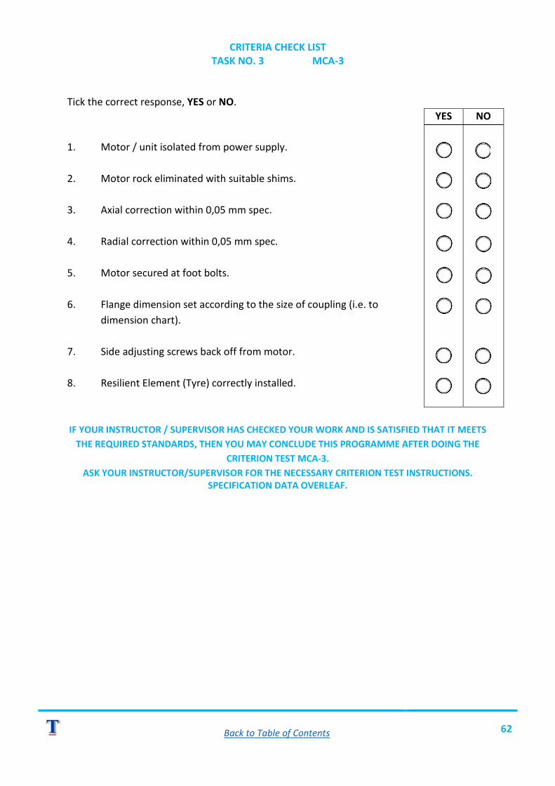
CRITERIA CHECK LIST TASK NO. 3 MCA-3
Tick the correct response, YES or NO.
1. Motor / unit isolated from power supply. 2. Motor rock eliminated with suitable shims. 3. Axial correction within 0,05 mm spec. 4. Radial correction within 0,05 mm spec. 5. Motor secured at foot bolts. 6. Flange dimension set according to the size of coupling (i.e. to dimension chart). 7. Side adjusting screws back off from motor. 8. Resilient Element (Tyre) correctly installed. IF YOUR INSTRUCTOR / SUPERVISOR HAS CHECKED YOUR WORK AND IS SATISFIED THAT IT MEETS
THE REQUIRED STANDARDS, THEN YOU MAY CONCLUDE THIS PROGRAMME AFTER DOING THE CRITERION TEST MCA-3.
ASK YOUR INSTRUCTOR/SUPERVISOR FOR THE NECESSARY CRITERION TEST INSTRUCTIONS. SPECIFICATION DATA OVERLEAF.
YES
NO

Back to Table of Contents 63
PROGRAMME NO. 4 - MCA-4 ALTERNATIVE ALIGNMENT METHOD
OBJECTIVE At the end of this programme you will be able to:
o Perform an alignment procedure using simple measuring / assessing equipment in the form of taper gauges and / or feeler gauges.
AIM OF THIS PROGRAMME This programme has been produced to offer you a visual and written explanation for performing an alternative method of assessing machinery alignment using the most basic of measuring equipment.

Back to Table of Contents 64
TASK NO. 1 - MCA-4 TAPER GAUGE
INSTRUCTIONS
o Read the Resource Notes beginning over page. o Obtain Video No. MCA-4. o Watch video through until you see either a "DISCUSSION" or "PRACTICAL" sign. o Perform the suggested exercise in your workbook or in your training workshop.
TURN PAGE FOR RESOURCE NOTES.

Back to Table of Contents 65
RESOURCE NOTES TASK NO. 1 - MCA-4
TAPER GAUGE A taper gauge is a simple measuring instrument designed to enable you to quickly assess the dimension of gaps, however it must only be used when a gap exists between parallel surfaces. It should also be noted that a "taper-gauge" is not a "high-precision" instrument and is not suitable for use where accuracies or tolerances below ± 0,10 mm are essential (With skilled use accuracies up to 0,05 mm can be realised with a taper gauge). A typical taper-gauge is the Starrett No. 270 which is graduated in both metric and imperial. The metric side provides readings from zero to four (0-4 mm) millimetres with each small division representing 0,05 mm.
Fig. 41
PRACTICAL APPLICATION For purposes of assessing alignment at the coupling faces a taper gauge can be used in the following ways. NOTE: It is assumed that all pre-alignment checks and motor rock (i.e. solid base) have been done as you learnt in earlier programmes. AXIAL TESTS (TOP AND BOTTOM)
o Mark each half-coupling to ensure that they always stay together in the same relationship.
o Slip the taper gauge into the gap at top and take a reading. o Rotate both half-couplings 180⁰. o Slip taper gauge into bottom gap and take a reading. o Calculate the difference between readings. o Use the formula for calculating shim thickness required:
(t = A x Cd) B

Back to Table of Contents 66
Fig. 42 TAKING AN AXIAL READING AT TOP
(NOTE: READ TAPER-GAUGE SCALE AS SHOWN IN THE INSET DIAGRAM). RADIAL CHECKS (TOP AND BOTTOM)
o Set coupling to align your marks at top. o Lay a 150 mm rule or a straight edge across the two half-couplings. o Assess the gap (if any) between bottom edge of straight edge and coupling half using
your taper-gauge.
Fig. 43
Adjust the gap to (near) zero by removing an equivalent amount of shims from under each motor foot. If the gap exists on the motor side - then add equivalent shims under each motor foot.

Back to Table of Contents 67
AXIAL ADJUSTMENT (AT SIDES)
Fig. 44
Observing coupling from above:
o Align coupling marks together 90⁰ from vertical. o Measure gap with taper-gauge and note down. o Rotate both couplings together by 180⁰. o Measure gap at position of marks - note down. o If difference exceeds 0,05 mm make the necessary adjustment using side adjusting
screws (A, B, C, D) after first slackening motor hold-down bolts. Note that in the diagrams we have exaggerated the motor position for purposes of visual explanation. In the illustrated example (Fig. 44) we would correct the axial error as follows:
o Tighten screw D until it contacts motor foot. o Slacken off screw B. o Slacken off screw C. o Tighten screw A to move motor slightly. o Re-tighten all motor hold-down bolts. o Re-check gap.
Repeat all above procedures until you have achieved ± 0,05 mm difference between both sides checked.

Back to Table of Contents 68
RADIAL ADJUSTMENT (AT SIDES)
Fig. 45
(NOTE: THE DIAGRAM ABOVE HAS BEEN EXAGGERATED FOR PURPOSES OF EXPLANATION.) Procedure for correction, in the illustrated example (Fig. 45) is as follows:
o Loosen and wind-out both screws A and B. o Tighten up, in exactly equal amounts, screws C and D until gap is near, or on, zero
mm. o Tighten hold-down bolts and re-check both axial and radial run-outs. o Make re-adjustments as necessary until a maximum of 0,05 mm axial and radial
error is achieved. o Upon completion of alignment, and after all motor hold-down bolts have been
secured, then slacken off all the side-adjusting screws (i.e. don't leave them to remain in contact with the motor's feet during operation).
NOW WATCH THE VIDEO PROGRAMME. TURN PAGE FOR SELF-CHECK EXERCISE.

Back to Table of Contents 69
TASK NO.1 SELF TEST EXERCISE
This is a practical exercise to be done on a training model in your training centre or workshop. INSTRUCTIONS Ask your Instructor for a suitable coupling to use and then perform the following:
o Perform a full alignment procedure using taper-gauge, feeler-gauge and straight edge.
o Have your Instructor / Supervisor check your finished work. o Evaluate your work using the criterion check list on the next page.
TURN PAGE FOR CRITERION CHECK LIST.

Back to Table of Contents 70
CRITERIA TEST CHECK LIST TASK NO. 1 MCA-4
Tick the correct response, YES or NO.
o Were the pre-alignment checks done first?
o Is the top and bottom axial-correction within 0,05 mm?
o Is the top and bottom radial-correction within 0,05 mm?
o Is axial-side adjustment within 0,05 mm?
o Is radial-side adjustment within 0,05 mm?
o Have the side-adjusting screws been backed off upon completion?
HAVE YOUR COURSE CONTROLLER OR SUPERVISOR CHECK YOUR WORK TO CONCLUDE THIS MODULE.
YES
NO