mechanical design features of the unilac - …lss.fnal.gov/conf/c721010/p103.pdf · ·...
TRANSCRIPT

MECHANICAL DESIGN FEATURES OF THE UNILAC
T. Niewodniczanski and E. MalwitzGesellschaft fur Schwerionenforschung mbH
Darmstadt, Germany
Summary
The paper reviews the design of the mechanical components of the UNILAC as well as some resultsof prototype tests and of different technologicalapproaches. Preliminary results on copper plating ofthe test cavities with Q values higher than 95 % oftheir theoretical value are discussed. Some dataabout the tank electroplating plant are given. Thepaper presents the mechanical design of the Wideroeand Alvarez structure and the single-gap cavities.Some details are given on the tank design as well ason the different versions of drift tUbes. A generaldescription of the cooling water system is included.
Introduction
After many years of design studies, prototypework, experiments with models and different technology-tests, the mechanical design of the UNILAC hasbeen completed. Nearly all main components of themachine are already ordered and the assembling ofthe first accelerator part - the Wideroe tank No 4 will start early in 1973. This cavity will be testedas the first unit of the whole machine under rfpower at the end of 1973. Parallel to this activitythe other Wideroe tanks, both Alvarez cavities andthe single-gap cavity groups will be preassembled inthe injector hall and afterwards moved into theaccelerator tunnel. It is planned to finish the mechanical assembling of the whole UNILAC in mid of1974.
Although the machine consists of many physically and mechanically different accelerating structures, its concept reflects the same design principles. This philosophy is based on the standardization of the sUb-components (e.g. 112 Alvarez drifttubes are equipped with only 5 different quadrupoletypes) and the possibility of preassembling the individual cavity sections and the successive boltingtogether the vacuum checked and roughly alignedunits into the final tanks. Furthermore, all theaccelerating structures are made up from copperplated mild steel.
Throughout the machine gold-wire gaskets andCon Flat flanges are used as high vacuum seals andrf contacts. The application of gold wire as themain rf and vacuum seal between the tank sections,end walls and drift tube supports was possible dueto the relative hard surface of the copper layerplated on the inner and front side of the tank sections.
The joining of the tank sections by gold wiregaskets enabled the reduction of the number of welding seams exposed to high vacuum to only one alongside the cavity. Although pretty good results havebeen obtained with vacuum tightness of the gold wirejoints during many years of exploitation (5,6), thegold wire gaskets are backed up allover by soft va-
cuum volumes sealed off to the atmospheric pressureby elastomer seals. The end walls of the tanks inall three different accelerating structures consistof thin copper plated steel plates (»membranes»)isolat.ed from the atmospheric pressure by a soft vacuum backing.
The design of the drift tubes for the Wideroeand Alvarez structures follows principles of seriesproduction, which provide not only cheap industrialfabrication but also fast rebuild~ng of damaged unitsfrom a small variety of spare components.
Copper Plating Technology
As it was already described before (2,3,4),from the early beginning of the UNILAC projectstudies it was aimed to base the cavity design onthe principle of electrolytically produced cavities.Initially the electroforming technique was envisaged and two single-gap cavities have been builtfor prototype evaluation. The results obtained (2)showed that although the physical properties ofthese cavities were excellent, the high cost ofproduction, especially in the cas~ of the 2 m diameter Alvarez tank sections, excluded this method.
Experience gained from an electrolytic processing program led to the decision of startingstudies of different methods and approaches ofcopper plating technology. Although a much thinnercopper deposit would be adequate for optimum rf conductivity (3) a copper thickness of 0.2 mm waschosen as a mechanically sound value.
The particular treatment was selected aftera few years of studies using different bath types,and the products of several companies have beentested, e.g., for the main acid copper bath the performance of seven different organic brighteningagents have been studied. Also different methodsof electrolytic degreasing as well as differentcopper or nickel strike treatments have been evaluated.
For comparing different electroplating solutions small sample cavities of a diameter of 30 cm,with a resonant frequency of 767 MHz, as well asdifferent flanges and plates have been copper plated. The prototypes were checked on their mechanical properties as: adhesion strength of the copperlayer to the steel, outgasing characteristics,roughness of the copper surface, and on their electrical properties as: dc conductivity of the copperlayer as well as Q-value of the sample cavities.
With the plating process described below itwas possible to obtain copper plated sample cavities with following reproducible properties: .
a) bright surface of the 0.2 mm thick copper deposit ;
103

electrolytic degreasing as b) withoutcurrenttime: 1 min
b) satisfactory sticking of the copper layer tothe steel base;
c) outgasing rate of 1-3·10- 11 Torr·l·sec- 1 cm- 2;
d) smoothing coefficient (steel surface roughnessto copper surface roughness ratio) III 10;
e) good scattering of the copper deposit intoholes and on the outer side of the cylinder aswell as relatively small excessive deposits onthe edges of the cylinder.
f) dc conductivity of the copper layer of 96 %lACS
1)
m)
n)
4
2
250 C; 5-7 A/dm2
air agitationcylinder rotationbath coolingbath circulation
water rinsing
water rinsing
200 m3 /h7-36 rpm60000 kcallh
5000 l/h
The following copper plating treatment waschosen for fabrication of UNILAC components:
g) Q-values of the sample cavities of about 96% oftheir theoretical value calculated for a dcconductivity of copper equal to 100 %lACS = 58· 10- 7 mhos· m- 1
•
Besides small cavities and samples also fullscale components of UNlLAC like a Wideroe stub lineprototype (fig. 3) have been satisfactory copperplated.
x)trade name of the supplier
hot water rinsing0)
For the plating of the UNILAC components (thebiggest Alvarez tank sections are 2 m in diameterand are 2.6 m long) a special electroplating plantis being installed (fig. 4). The hall for this purpose has a floor area of 620 m2 and has a 420 m3
pit, a 12 V/10 kA rectifier and 7 containers withthe volume of 18 m3 each.
SolutionProcessContainer No
6 acid copper bath CUSo4· 5(H2o)220 gil(Cupatier-bath H2S04 55 gil"80 L") x) Cu ion 60g/1
Cl ion 60 mg/lbrightening agent "Cu 407" 1.5 1/10000 Ahsmoothing agent "Cu 607" 1.5 1/10000 Ahdetergent agent "807" 0.8 1/10000 Ah
5 nickel strike H3Bo3 40 gilNiC12 90 gilNiSo4 270 gilNi ion 80 gilCl ion 27 gil
main brightening agent 1 1/10000 Ahdetergent agent 0,5 1/10000 Ah
50 0 C; pH=4;10 min; 3 A/dm 2
4 water rinsing
4 water rinsing
Mechanical Design of UNILAC
The design principles of single-gap cavitiesare nearly identical to those of the Alvarez struc-
In the case of the Alvarez structure eachdrift tUbe is supported by two adjustable stems. Thetwo-stem design was chosen, after several experiments with prototypes, in order to minimize transversemechanical vibrations. The rf end walls ("membranes")are similar to those used in the single-gap cavities. They are backed with soft vacuum and clampedon the cast iron spiders (fig. 6. 15). The rf driveloops are isolated from the high vacuum by ceramicdomes covered with a semiconductor layer. Besidesthe fine tuning with slug tuners. a solid bar isbeing used for the rough adjusting of the field distribution inside Alvarez cavities (10).
In the case of Wideroe the coaxial-line structure with magnetic focussing in "outer" drift tubes.which are supported by the tank wall. was chosen(fig. 2). Contrary to the twin line structure, thissolution makes the adjusting and the supply of DCcurrent and cooling water to the drift tubes andquadrupoles simpler. The inner drift tubes withoutquadrupoles are screwed on the sections of innerconductor main line. The rf power coupling loopswith domes as well the slug tuners are placed always in the last stub line of each Wideroe tank.For coarse tuning of the field pattern one can useshorting plates of the stub lines (fig. 5).All components of the Wideroe cavities. especially innerconductor main line, inner drift tubes and stubline shorting plates are cooled separately in orderto control the thermal expansion.
The accelerating structure of UNILAC consistsof three main components: 4 Wideroe tanks. 2 Alvarezresonators and two groups of 10 single-gap cavitieseach (1).
as d)
5% H2S04or 10% HBF420 0 C, 30 sec
l\laoH: 30 gilNa2Co 3: 40 gil5-10 A/dcm2
50 - 600 Ctime: 4 min withpolarity reversion
acid bath
sulfuric acidbath
Electrolytic degreasing andrust removing
degreasing withwater vapor beam10 kp/cm, 1800 C
3
4 water rinsing
3
2 water rinsing
i)
k)
h)
g)
e)
d)
b)
c)
f)
a)
104

ture (5, 6). The coarse tuning is provided bychanging the gap length. In contrast to the halfdrift tUbe bodies, the quadrupoles inside can be adjusted transversally to the beam axis from the outside of the cavities (fig. 7).
For the cooling of the cavities and thecopper drift tubes treated water will be used. Toprevent corrosion, water quality will be adjustedto following specification:
The magnet and rf generator cooling circuits will have a central water processing plantand local ion exchangers.
Temperature of the inlet water in the coolingcircuits is controlled to provide a constant meantemperature of 26 ± 10 C for the tank walls fordifferent rf power levels.
The cavity water system provides cooling andclose temperature control for cavity walls anddrift tubes. Due to the different rf power lossesin the structure during different operating modes(different accelerated ions, accelerating fieldlevels and duty cycles) each cavity has to becooled by an independent primary circuit.
The cooling system of magnets, which consists of stainless steel and copper, will havewater of electrical conductivity lower than 20 ~S/cm.
For cooling of rf generators, where the coolingfluid must be fed by a short insulating path tohigh potential components water conductivity mustbe lower than 1 ~S/cm.
9 - 10< 100 ~S/cm
25 - 30 ppm< 10 ppm< 1 ppm< 0.1 ppm< 0.02 ppm
pH valueelectrical conductivityhydrazinammoniaironcopperoxygen
Drift tubes
All tank sections are manufactured from mildsteel being copper plated afterwards. The thicknessof the tank walls (22 - 32 mm) makes it possible tomachine Con Flat-flanges directly on the wall material. Contrary to other structures, the Alvareztanks are machined conically (2.4 mm/m). The innersurface of both Alvarez and single gap-cavity tanksections have to meet tolerances ± 0.5 mm and asurface roughness less than 16 ~m before theplating treatment. In the case of Wideroe structure,due to the relatively small loss of rf power onthe cavity walls, the inner surfaces of the tanksare only ground. The cooling of the tank wallsthroughout the accelerator is provided by waterjackets (3 - 5 mm thick).
Tanks
Drift tUbes for the different acceleratingstructures are based on common design principles.Their fabrication technology as electron beam welding, vacuum brazing, copper plating of the stainless steel and monel, heli-arc welding etc, whichwas finally chosen after many experiments with prototypes, can be seen from the figures 9 - 14. DFHCis chosen allover. The mechanically stressed parts,like stems and flanges, are made mainly fromcopper plated monel.
The quadrupoles are positioned in the drifttube bodies by a tight fit of the yoke inner diameter to a shoulder cut into the drift tUbe caps.The material for the first eight quadrupoles of theWideroe structure has a 20 kG/10 De quality in orderto obtain field gradients up to 10.5 kG/em. The ironfor other quadrupoles has the quality 16 kG/3D De.Quadrupole apertures increase along the acceleratoras follows: Wideroe tank 1 20-30 mm, tank 2 - 4and Alvarez tank 1 30 mm, Alvarez tank 2 35 mm,and single-gap cavities 45 mm (4).
All systems are equipped with plate heat exchangers only. The cooling water in the secondarysystem is protected against any interaction withoxygen.
Normally an open cooling tower plant willremove the heat load from the secondary circuit.However for full power operation modes of theaccelerator, supplementary town water may be required on a few summer days.
There is soft vacuum inside the stems anddrift tUbes. Flexible bellows on stems lie in thecase of Alvarez structure outside the tank periphery (9). In Wideroe tanks they are inside theperiphery and are water cooled.
The caps of the half drift tUbes of thesingle-gap cavities have been made of pure aluminium explosion clad on copper. As the experimentswith prototypes showed (7, 8), this materialguarantees lower spark rate and x-ray level andshows better performance during conditioning andless tendency to surface contaminations as well.
Cooling system
The UNILAC cooling system is diVided, on theprimary side, into four different circuits according to the cooling medium quality (fig. 16).
Acknowledgments
The authors would like to express their appreciation to the engineering staff of the UNILACProject - to every colleague, who has contributedin designing, building and testing prototypes aswell as preparing the production of the mechanicalcomponents for the UNILAC, and especially to paytribute to Or. Dieter Bohne, Project Leader, whoseprevious work is the basis for virtually all that isreported here.
We wish also to acknowledge the helpful aovice, the generous exchange of engineering ideasand documents we got continuously in the past yearsfrom the BNL, CERN, LASL, LRL and NAL laboratories.We bear in mind that most of the technical solutionsdescribed here have been inspired by other membersof the accelerator-builder community.
105

References
Ch. Schmelzer. D. B6hne. "GSI. a New Heavy-Ion Research Facility". Proc. of the 1970 Proton LinearAccelerator Conference. Batavia (1970), p. 981.
2 D. B6hne. "Linac Cavity Technology". Proc. of the1969 Particle Accelerator Conference, IEEE Trans.on Nucl. Sci.. Vol. 16, No 3. p. 390. (1969).
3 D. B6hne. "RF-Properties of Surfaces in ResonantCavities", UNILAC Projektbericht No 3, GSI 72-1.p. 10. (1972).
4 B. Langenbeck, "Quadrupoles for the AlvarezDrift Tubes", UNILAC Projektbericht No 3. GSI72-1.p. 6, (1972).
5 D. B6hne and E. Malwitz. "The Single-Gap CavityStructure". UNILAC Bericht No 2-69, p. 66 (1969).
6 E. Malwitz. "The Single-Gap Cavity Design",UNILAC Bericht No 1-70 (1970).
7 O. B6hne. U. Grundinger. "Spark Rate and X-RayLevel of a Single-Gap Resonator with DifferentGap-Electrode Materials". UNILAC ProjektberichtNo 1. GSI 71-4, p. 11. (1971).
8 O. B6hne. W. Karger, E. Miersch, W. R6ske.B. Stadler. "Sparking Measurements in a Single-GapCavity", Proc. of the 1971 Particle AcceleratorConf., IEEE Trans. on Nucl. Sci .• Vol.18. No 3.p. 568. (1971).
9 D. B6hne. "High Power Test of an Alvarez DriftTube Stem". UNILAC Projektbericht No 1. GSI 71-4.p. 18. (1971).
10 O. B6hne, "Tuning Bar for Alvarez Cavities",UNILAC Projektbericht No 1. GSI 71-4. p. 19 (1971).
11 E. Malwitz. "Consideration on Possible Corrosionin the Cooling System of the UNILAC". UNILAC-Projektbericht No 2. GSI 71-6, p. 18 (1971) •
.~~ .
iII
f;i
fI"
c'
"
i: :
.J!ii""
-, ; i
-17~
I'IIIiW:
.,
lu
QQ",- ',•c:'- • ..r :. .'J~' .... ..
Fig. 1 General view of the Wider6e and Alvarez structures
106

,~------
~-
- -. ~- -
; . ---l- __
\ I '00 __
, ,
, -'''u ' c
-.:t,<L
4o3Q)
'.-1:>
Q)
l.<:J
-j..J(J
:Jl.<
-j..J
Ul
NQ)
l.<III:>.-t<t:
"0cIII
Q):0l.<Q)
"0'.-13
Q)
.r:-j..J
.-tIIIl.<Q)
cQ)
(CJ
I,
TI
:.::::;.:=-:;.~1
'::::::::::::----------'-:--1~
I---------- -- ,,-,---+I
.,-.1
\1
!I
:!
! I
i I
I
.r
,i
Ij
i-,.'
'1
,i:
II,';,:::::::-~H
, I
II- j'1,
I
~-l
,',;:- - -Ij!;- -fe,
: :I,:
I
iII, I
!I
il
I
I: JL:__ ~~~-L" ;j \I '.J
107
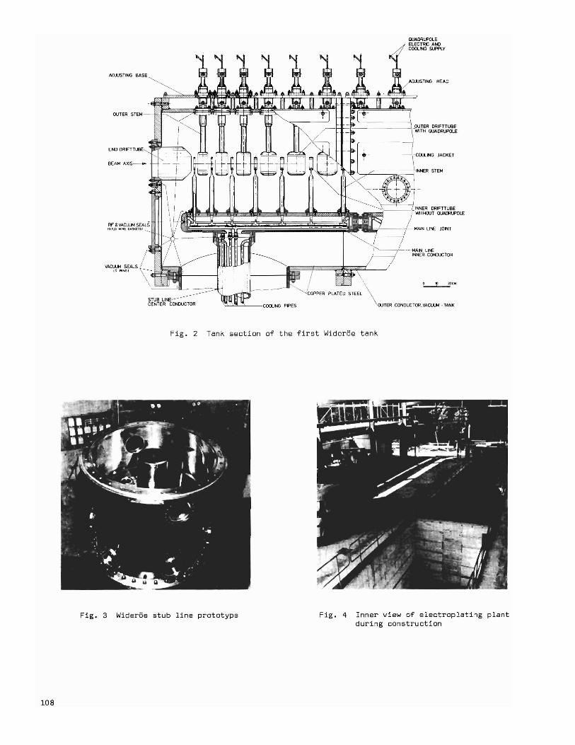
AOJUSTING
OUTER STEM-
VACl.U1 SEALSto-RING)
STUB LINECENTER CONDUCTOR
Fig. 2
QUAllALf>OLEELECTRIC ANOCOOLING SlffLY
AOJUSTING HEAO
_OUTER llAlFTTUBEWITH QUADRUPOlE
- -COOLING JACKET
'"~ l....".L==::;::;;:;;::=j-INNER STEM
JOINT
-·--MAIN lIfIEI_R CQNJUCTOR
'-JCOPPER PLA:ED'STEE:\
""='----"~--COOLINGPIPES OUTER CONDUCTOR_ VACUUM - TANK
Tank section of the first Wideroe tank
108
Fig. 3 Wideroe stub line prototype Fig. 4 Inner view of electroplating plantduring construction

GOLD WIRE GASKET
RF-CONTACT
PORT FOR TUNER
VACUUM SEAL
("O"RINGI
GOLD WIRE GASKET
TUNING MECHANISM
FOR SHORTING PLAT
PORT FOR RFPOWER FEED
STUB LINEINNER CONDUCTOR
-- STUB LINE TANK
- SHORTING PLATE
VERTICAL ADJUSTING DEVICE
MAIN LINEINNER CONDUCTOR
INNER DRIFT TUBE
STEM
TANK
LATERAL &LONGITUDINALADJUSTINGDEVICE
iotR6E
CONFL AT FLANGE
COOLING TUBES~ SOFT VACUUM
10 20 eM
Fig. 5 Sectional view of the Wideroe stub line
109

BULK HEADICAST IRON I
VACUUM SEALI"D"RINGI
SPIDER WATER IN
TANK WALLICOPPER PLATED STEEL!
COPPER GASKET
SOFT VACUUM RF & VACUUM SEAL!GOLD WIRE GASKETI
Fig. 6 Alvarez tank termination
QUADRUPOLE CLAMP RING -~
~HALF DRIFT TUBE \ "
(r
TUBE JOINT
ALIGNMENT TARGET FIT
CONFLAT GASKET
COOL ING CHANNEL
TANK WALL
I
IrATMOSPHERIC PRESSURE
I./I COOLING CHANNEL
, I BEAM TUBE
/ / QUADRUPOLE.rMAGNET
/1. GAP TUNING~/'" MECHANISM
..~
_____-------- QUADRUPOLE SUSPENSION~+Q:~:::;:+~;::::::,;
\
SPIDER ~,,,_
QUADRUPOLE
ADJUSTMENT
HIGH VACUUM
J_
GEARS ~
SOFT VACUUM
SUPPORT STUD -------,--- _
TANK RF END WALL
(JFig. 7 Single- gap caVity intertank area
no

·Fig. 8 Prototype of two single-gap cavities Fig. 9 Components of the Alvarez drift tube
WATER lOUT!
QUADRUPOLE LEEDS
SOFT VAClIUIrot_.l'l.."~'"
FOR DRIFT TUBE
STEM CLAMPING COLLAR
VACUUMI"O"RING I
SOFT VACUUM
INNER STEM(COPPER!
HELIARC WELDED
STUB------IOFHC-COPPERI ~~~~~
END CAPIOFHC-COPPER!
BEAM TUBE(OFHC-COPPER!
DRIFT TUBE BODY
EXCENTER KEY(VERTICAL &LATERALADJUSTMENT!
SOFT VACUUM
SILVER BRAZED
ECCENTER KEY HOLES(LONGITUDINAL ADJUSTMENT)
Fig. 10 Alvarez drift tube
III

f-'f-'IV
/~ L.,,:/N.'4-q ~.. .~ ~* ..,.,;; .~:,~:.."* /
.,.~' ."7//
Fig. 11 Wider6e "outer" drift tubequadrupole prototype
SIlVnM:AZEOIFCHlI
VACUU'" SEALl'O-'IIINGI
COPPER GASKET
SOFT VACUUM
DRIFT TUBE
COOLING CHANNELS
INNER CONDUCTORICOW£Il PLUEDSTIEIELI
COOlING TUBEISTUll
-E- -~
COOliNG CHANNEL
ClWPElI IOfHC I
STEM
COPPE'l PUfEO STEEL
GOLD WIRE GASKET
WATER liN'
STAINLESS STEEL
WATER lOUT)
ELECTRON BEA~ WELDED
% "">6 C 'M~CONFLATFLANGEK\"l (STAINLESS STEEL)
t - I COPPER IOFHC I-_._.- _L.+-'rIr-
DRIFT TUBE CAPSEXPLOSION CLAD ALU~INUMI
Fig. 12 Wider6e "inner" drift tube
u ~ 10 elll
Fig. 13 Single-gap cavity half drift tube
Fig. 14 Single-gap cavity half drifttube prototype

BULK HEAD
DRIFT TUBE
GATE VALVE -------1t(J)i!!1~li
./TUR80MOLECULAR PUMP--./'"
ROUGHING VALVE
__ FORELINE TRAP
-----tll--- Roors PUMP
L:.ROTARY PUMP
Fig. 15 Vacuum system of the Alvarez tank
HEAT SOURCES-
-er ~~N~~LR-TER~ ~;~~~RA TuRE-
~ ~:~~~URE-
_, ION EXCHANGER
-@- FLOW-METER
-{j}-REsmI/JTV-METER
~TEMPEFiATURt-CONTROLLER
<>- SERVOAMPL JFIER
Y DRAIN
CHECK-VALVE
Fig. 16 Schematic of the UNILAC cooling system
~~~~H:NGER
a EXPANSION TANK
~o , I-£ATlNG UNIT
@ PUMPS
¢> STRAINER
+ PNEUMATlC-3 WAY-VALVE
"*REMOTELY CONTROLLEDVALVE
$ VALVE
'i iJUPLEX-"ILTER
-i~PRESSURE '. RELEASEANGLE VALVE
~"'PRESSURERELEASE·VALVE
~cArlieu 0 LEVELREGULATOR
113