mechanical engineering lab-ii
TRANSCRIPT
LABORATORY MANUAL
ON
MECHANICAL ENGINEERING LAB-II
4TH SEMESTER,
DEPT OF MECHANICAL ENGG.,
GOVERNMENT POLYTECHNIC NAYAGARH
PREPARED BY: Mrs. SUSHREE SASMITA SAHOO, LECTURER
1
LIST OF EXPERIMENTS
1. Study about 2 stroke, 4 stroke petrol and diesel engine
models.
2. Determine the brake thermal efficiency of single cylinder petrol
engine.
3. Determine the brake thermal efficiency of single cylinder diesel
engine.
4. Determine the BHP, IHP and BSFC of multi cylinder petrol
engine by Morse test.
5. To determine the mechanical efficiency of an air compressor.
6. Study of pressure measuring devices like Manometer &
Bourdon tube pressure gauge.
7. Verification of Bernoulli's theorem.
8. Determination of the co-efficient of discharge (Cd) from
venturimeter.
9. Determination of Cc, Cv and Cd from orifice meter.
10. Determination of Darcy’s coefficient from flow through pipe.
2
EXPERIMENT - 1 AIM OF THE EXPERIMENT: -
To study about two stroke and four stroke petrol and diesel engine models.
APPARATUS REQUIRED: -
SL. NO. NAME OF THE APPARATUS SPECIFICATION QUANTITY
01 Model of petrol engine 2-stroke 1
02 Model of petrol engine 4-stroke 1
03 Model of diesel engine 2 stroke 1
04 Model of diesel engine 4 stroke 1
THEORY: -
TWO STROKE PETROL ENGINE
A two stroke cycle petrol engine was devised by Dug lad clerk in 1880.
In this cycle, the suction, compression, expansion, and exhaust takes place during
two strokes of the piston. It means that there is one working stroke after every
revolution of the crank shaft.
A two stroke engine has ports instead of valves.
The four stages of a two stroke petrol engine are described below:
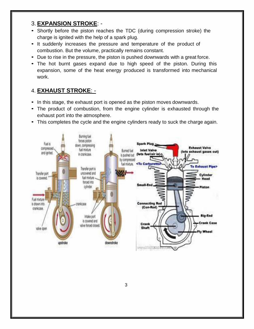
1. SUCTION STAGE: -
• In this stage, the piston, while going down towards BDC, uncovers both the
transfer port and the exhaust port.
• The fresh fuel-air mixture flows into the engine cylinder from the crank case.
2. COMPRESSION STAGE: -
• In this stage, the piston, while moving up, first covers the transfer port.
• After that the fuel is compressed as the piston moves upwards BDC to TDC.
• In this stage, the inlet port opens and fresh fuel-air mixture enters into the crank
case.
3
3. EXPANSION STROKE: -
• Shortly before the piston reaches the TDC (during compression stroke) the
charge is ignited with the help of a spark plug.
• It suddenly increases the pressure and temperature of the product of
combustion. But the volume, practically remains constant.
• Due to rise in the pressure, the piston is pushed downwards with a great force.
• The hot burnt gases expand due to high speed of the piston. During this
expansion, some of the heat energy produced is transformed into mechanical
work.
4. EXHAUST STROKE: -
• In this stage, the exhaust port is opened as the piston moves downwards.
• The product of combustion, from the engine cylinder is exhausted through the
exhaust port into the atmosphere.
• This completes the cycle and the engine cylinders ready to suck the charge again.
4
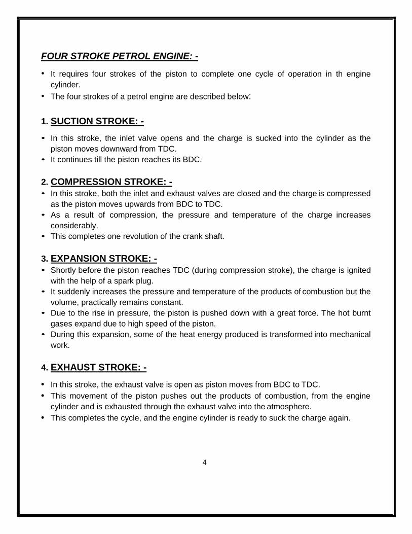
FOUR STROKE PETROL ENGINE: -
• It requires four strokes of the piston to complete one cycle of operation in th engine
cylinder.
• The four strokes of a petrol engine are described below:
1. SUCTION STROKE: -
• In this stroke, the inlet valve opens and the charge is sucked into the cylinder as the
piston moves downward from TDC.
• It continues till the piston reaches its BDC.
2. COMPRESSION STROKE: -
• In this stroke, both the inlet and exhaust valves are closed and the charge is compressed
as the piston moves upwards from BDC to TDC.
• As a result of compression, the pressure and temperature of the charge increases
considerably.
• This completes one revolution of the crank shaft.
3. EXPANSION STROKE: -
• Shortly before the piston reaches TDC (during compression stroke), the charge is ignited
with the help of a spark plug.
• It suddenly increases the pressure and temperature of the products of combustion but the
volume, practically remains constant.
• Due to the rise in pressure, the piston is pushed down with a great force. The hot burnt
gases expand due to high speed of the piston.
• During this expansion, some of the heat energy produced is transformed into mechanical
work.
4. EXHAUST STROKE: -
• In this stroke, the exhaust valve is open as piston moves from BDC to TDC.
• This movement of the piston pushes out the products of combustion, from the engine
cylinder and is exhausted through the exhaust valve into the atmosphere.
• This completes the cycle, and the engine cylinder is ready to suck the charge again.
5
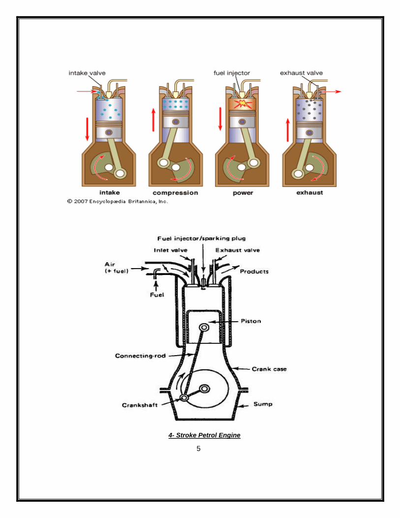
4- Stroke Petrol Engine
6
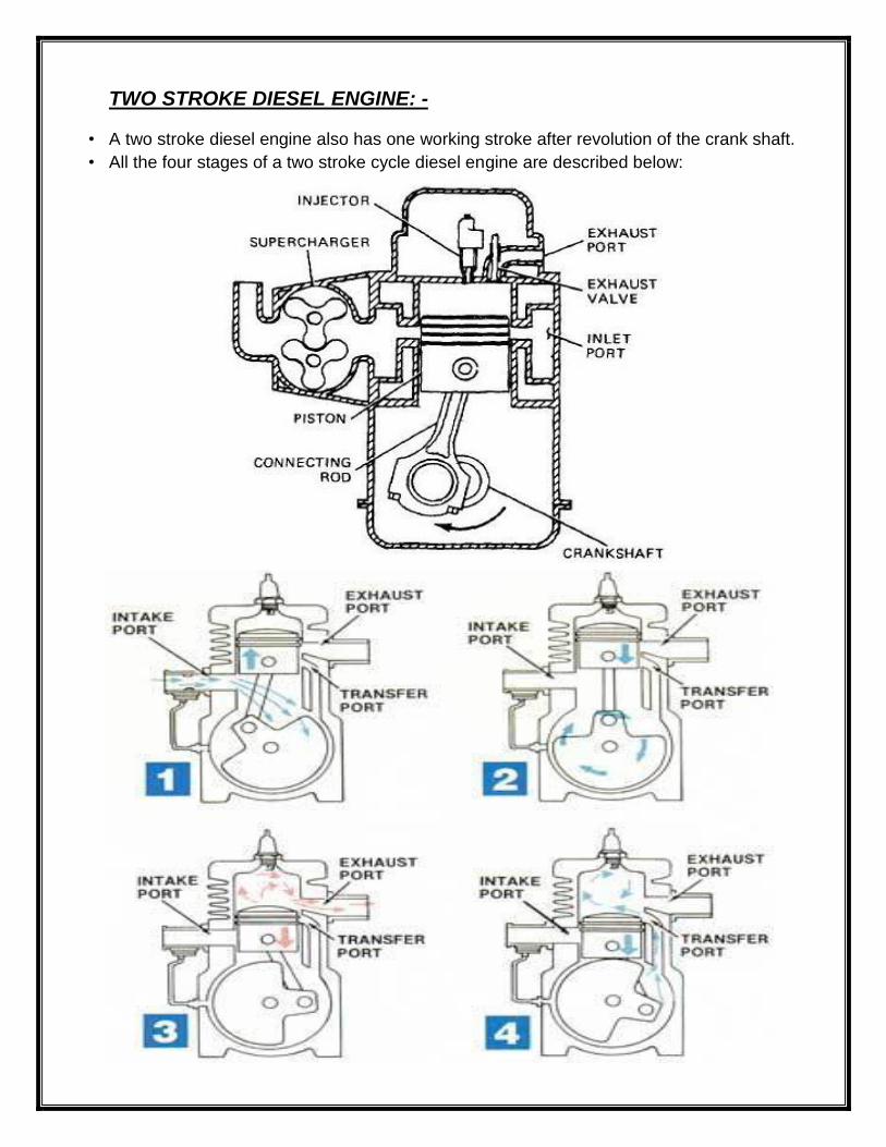
TWO STROKE DIESEL ENGINE: -
• A two stroke diesel engine also has one working stroke after revolution of the crank shaft.
• All the four stages of a two stroke cycle diesel engine are described below:
7
1. SUCTION STAGE: -
• In this stage, the piston while going down towards BDC uncovers the transfer port and
the exhaust port.
• The fresh air flows into the engine cylinder from the crank case.
2. COMPRESSION STAGE: -
• In this stage, the piston while moving up, first covers the transfer port and then
exhausts post.
• After that the air is compressed as the piston moves upward.
• In this stage, the inlet port opens and the fresh air enters in the crank case.
3. EXPANSION STAGE: -
• Shortly before the piston reaches the TDC (during compression stroke), the fuel oil is
injected in the form of very fine spray into the engine cylinder through the nozzle
known as fuel injection valve.
• At this moment, temperature of the compressed air is sufficiently high to ignite the fuel.
It suddenly increases the pressure and temperature of the products of combustion.
• Due to increase in pressure, the piston is pushed with a great force. The hot burnt
gases expand due to high speed of the piston.
• During the expansion, some of the heat energy produced is transformed into
mechanical work.
•
4. EXHAUST STAGE: -
• In this stage, the exhaust port is opened and the piston moves downwards.
• The product of combustion from the engine cylinder is exhausted through the exhaust
port into the atmosphere.
• This completes the cycle, and the engine cylinder is ready to suck the air again.
FOUR STROKE DIESEL ENGINE: -
• It is also known compression ignition engine because the ignition takes place due to the
heat produced in the engine cylinder at the end of compression stroke.
• The four stokes of the diesel engine are described below:
8
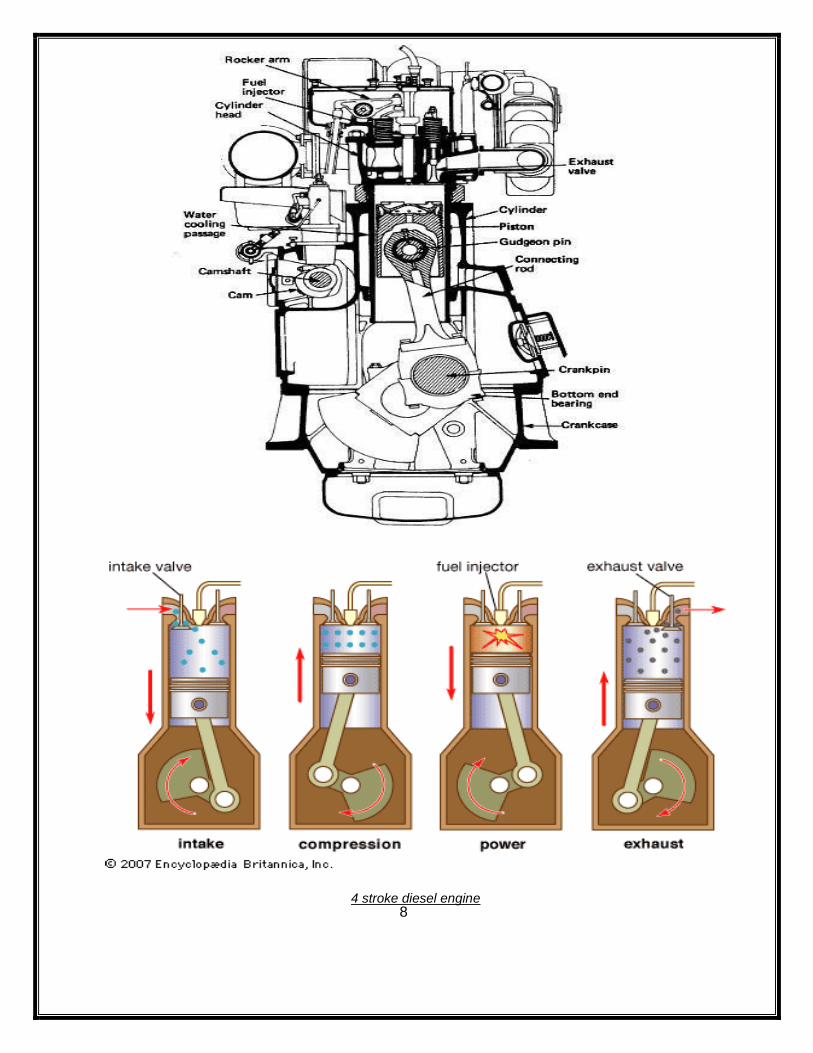
4 stroke diesel engine
9
1. SUCTION STROKE: -
• In this stroke, the inlet valve opens and the pure air is sucked into the cylinder as the
piston moves downwards from TDC.
• It continues till the piston reaches in the BDC.
2. COMPRESSION STROKE: -
• In this stroke, both the valves are closed and the air is compressed as the piston
moves upwards from BDC to TDC.
• As result of compression, pressure and temperature of the air increases considerably.
• This completes the revolution of the crank shaft.
3. EXPANSION STROKE: -
• Shortly before the piston reaches the TDC, fuel is injected in the form of very fine
spray in to the engine cylinder through the nozzle known as fuel injector or fuel
injection valve.
• At this moment, temperature of the compressed air is sufficiently high to ignite the fuel.
It suddenly increases the pressure and temperature of product of combustion.
• Due to increased pressure, the piston is pushed down with a great force. The hot burnt
gases expand due to high speed of the piston.
• During the expansion, some of heat energy is transformed into mechanical work.
4. EXHAUST STROKE: -
• In this stroke the exhaust valve is open as the piston moves from BDC to TDC.
• This movement of the piston pushes out the product of combustion from the engine
cylinder through the exhaust valve into the atmosphere.
• This completes the cycle and the engine cylinder is ready to suck the fresh air again.
CONCLUSION: -
From the above experiment we have successfully studied about the two stroke and four
stroke petrol and diesel engine.
10
POST LAB QUESTION:
1. What are the different stages in two stroke petrol engine?
2. What are the different stages in two stroke diesel engine?
3. What are the different stages in four stroke petrol engine?
4. What are the different stages in four stroke diesel engine?
5. Define stroke.
6. What is the function of spark plug?
7. What is the function of fuel injector?
8. What is the function of inlet and outlet valve?
9. Define piston speed.
10. What is the function of transfer port?
11
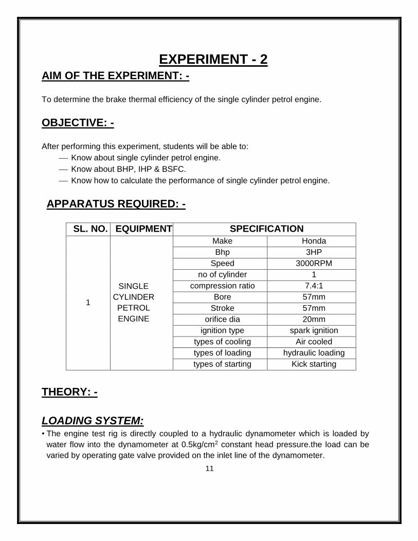
EXPERIMENT - 2 AIM OF THE EXPERIMENT: -
To determine the brake thermal efficiency of the single cylinder petrol engine.
OBJECTIVE: -
After performing this experiment, students will be able to:
Know about single cylinder petrol engine.
Know about BHP, IHP & BSFC.
Know how to calculate the performance of single cylinder petrol engine.
APPARATUS REQUIRED: -
THEORY: -
LOADING SYSTEM: • The engine test rig is directly coupled to a hydraulic dynamometer which is loaded by
water flow into the dynamometer at 0.5kg/cm2 constant head pressure.the load can be
varied by operating gate valve provided on the inlet line of the dynamometer.
SL. NO. EQUIPMENT SPECIFICATION
1
SINGLE
CYLINDER
PETROL
ENGINE
Make Honda
Bhp 3HP
Speed 3000RPM
no of cylinder 1
compression ratio 7.4:1
Bore 57mm
Stroke 57mm
orifice dia 20mm
ignition type spark ignition
types of cooling Air cooled
types of loading hydraulic loading
types of starting Kick starting
12
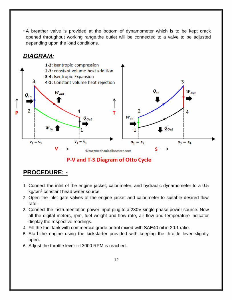
• A breather valve is provided at the bottom of dynamometer which is to be kept crack
opened throughout working range.the outlet will be connected to a valve to be adjusted
depending upon the load conditions.
DIAGRAM:
PROCEDURE: -
1. Connect the inlet of the engine jacket, calorimeter, and hydraulic dynamometer to a 0.5
kg/cm2 constant head water source.
2. Open the inlet gate valves of the engine jacket and calorimeter to suitable desired flow
rate.
3. Connect the instrumentation power input plug to a 230V single phase power source. Now
all the digital meters, rpm, fuel weight and flow rate, air flow and temperature indicator
display the respective readings.
4. Fill the fuel tank with commercial grade petrol mixed with SAE40 oil in 20:1 ratio.
5. Start the engine using the kickstarter provided with keeping the throttle lever slightly
open.
6. Adjust the throttle lever till 3000 RPM is reached.
13
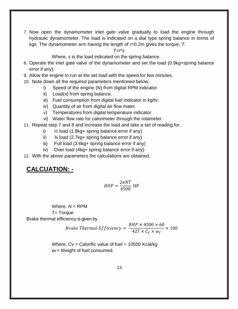
7. Now open the dynamometer inlet gate valve gradually to load the engine through
hydraulic dynamometer. The load is indicated on a dial type spring balance in terms of
kgs. The dynamometer arm having the length of r=0.2m gives the torque, T.
T=r*s
Where, s is the load indicated on the spring balance.
8. Operate the inlet gate valve of the dynamometer and set the load (0.9kg+spring balance
error if any).
9. Allow the engine to run at the set load with the speed for few minutes.
10. Note down all the required parameters mentioned below.
i) Speed of the engine (N) from digital RPM indicator.
ii) Load(s) from spring balance.
iii) Fuel consumption from digital fuel indicator in kg/hr.
iv) Quantity of air from digital air flow mater.
v) Temperatures from digital temperature indicator.
vi) Water flow rate for calorimeter through the rotameter.
11. Repeat step 7 and 8 and increase the load and take a set of reading for
i) ½ load (1.8kg+ spring balance error if any)
ii) ¾ load (2.7kg+ spring balance error if any)
iii) Full load (3.6kg+ spring balance error if any)
iv) Over load (4kg+ spring balance error if any)
12. With the above parameters the calculations are obtained.
CALCUATION: -
𝐵𝐻𝑃 =2𝜋𝑁𝑇
4500 HP
Where, N = RPM
T= Torque
Brake thermal efficiency is given by
𝐵𝑟𝑎𝑘𝑒 𝑇ℎ𝑒𝑟𝑚𝑎𝑙 𝐸𝑓𝑓𝑖𝑐𝑖𝑒𝑛𝑐𝑦 = 𝐵𝐻𝑃 × 4500 × 60
427 × 𝐶𝑉 × 𝑤𝑓× 100
Where, Cv = Calorific value of fuel = 10500 Kcal/kg
wf = Weight of fuel consumed.
14
CONCLUSION: -
The brake thermal efficiency of single cylinder petrol engine is found to be _________.
POST LAB QUESTIONS: -
i) Explain the working of petrol engine.
ii) Draw P-V & T-S diagram of petrol engine.
iii) Which device is used to measure the brake power?
iv) State different strokes of petrol engine.
v) What type of loading is taken in this experiment?
vi) Define brake thermal efficiency.
15
EXPERIMENT - 3 AIM OF THE EXPERIMENT: -
To determine the brake thermal efficiency of the single cylinder diesel engine.
OBJECTIVE: -
After performing this experiment student will be able to:
Know about single cylinder diesel engine.
Find the brake thermal efficiency of the single cylinder diesel engine
APPARATUS REQUIRED: -
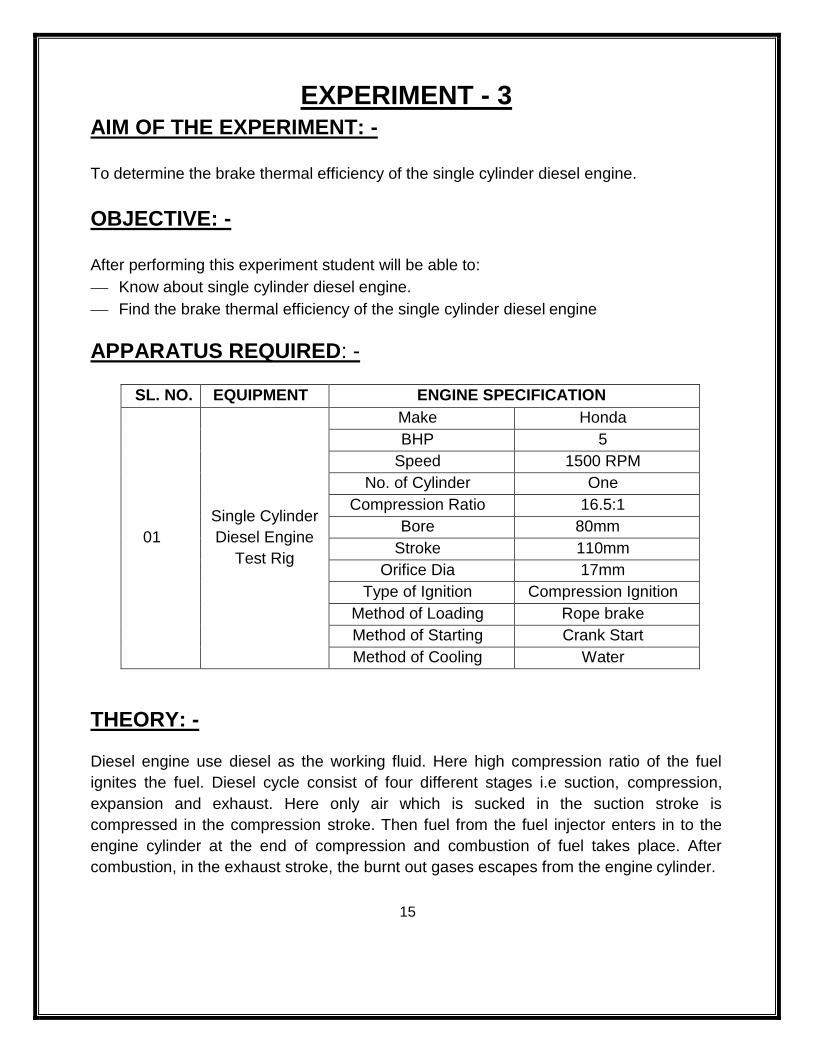
SL. NO. EQUIPMENT ENGINE SPECIFICATION
01
Single Cylinder
Diesel Engine
Test Rig
Make Honda
BHP 5
Speed 1500 RPM
No. of Cylinder One
Compression Ratio 16.5:1
Bore 80mm
Stroke 110mm
Orifice Dia 17mm
Type of Ignition Compression Ignition
Method of Loading Rope brake
Method of Starting Crank Start
Method of Cooling Water
THEORY: -
Diesel engine use diesel as the working fluid. Here high compression ratio of the fuel
ignites the fuel. Diesel cycle consist of four different stages i.e suction, compression,
expansion and exhaust. Here only air which is sucked in the suction stroke is
compressed in the compression stroke. Then fuel from the fuel injector enters in to the
engine cylinder at the end of compression and combustion of fuel takes place. After
combustion, in the exhaust stroke, the burnt out gases escapes from the engine cylinder.
16
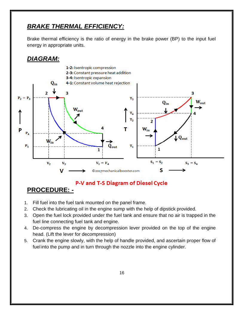
BRAKE THERMAL EFFICIENCY:
Brake thermal efficiency is the ratio of energy in the brake power (BP) to the input fuel
energy in appropriate units.
DIAGRAM:
PROCEDURE: -
1. Fill fuel into the fuel tank mounted on the panel frame.
2. Check the lubricating oil in the engine sump with the help of dipstick provided.
3. Open the fuel lock provided under the fuel tank and ensure that no air is trapped in the
fuel line connecting fuel tank and engine.
4. De-compress the engine by decompression lever provided on the top of the engine
head. (Lift the lever for decompression)
5. Crank the engine slowly, with the help of handle provided, and ascertain proper flow of
fuel into the pump and in turn through the nozzle into the engine cylinder.
17
6. When maximum cranking speed is attained, pull the decompression lever down, now.
The engine starts. Allow the engine to run and stabilize. (Approximately 1500 RPM.
The engine is a constant speed engine fitted with centrifugal governor)
7. Now lead the engine by placing the necessary dead weights on the weighing hanger,
to load the engine in steps of 1/4, 1/2, 3/4, full and 10% over load. Allow the engine to
stabilize on every load change.
8. Record the following parameters indicated on the panel instruments on each load step.
A) Speed of the engine from RPM indicator.
B) Rate of fuel from burette.
9. Exact load in kg (W) on the engine by adding the amount of weight added on the pan
in kg (W1) plus weight of pan in kg (W2) minus spring balance reading in kg (W3)
10. To stop the engine after the experiment is over push/pull the governor lever towards
the engine cranking side.
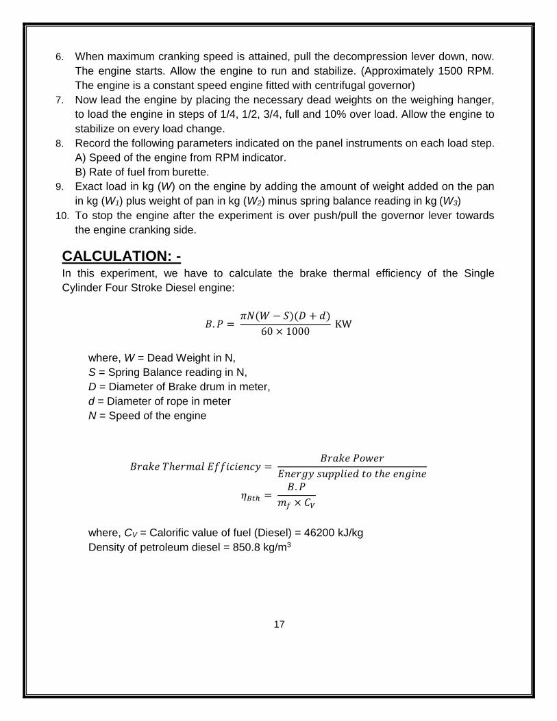
CALCULATION: - In this experiment, we have to calculate the brake thermal efficiency of the Single
Cylinder Four Stroke Diesel engine:
𝐵. 𝑃 = 𝜋𝑁(𝑊 − 𝑆)(𝐷 + 𝑑)
60 × 1000 KW
where, W = Dead Weight in N,
S = Spring Balance reading in N,
D = Diameter of Brake drum in meter,
d = Diameter of rope in meter
N = Speed of the engine
𝐵𝑟𝑎𝑘𝑒 𝑇ℎ𝑒𝑟𝑚𝑎𝑙 𝐸𝑓𝑓𝑖𝑐𝑖𝑒𝑛𝑐𝑦 = 𝐵𝑟𝑎𝑘𝑒 𝑃𝑜𝑤𝑒𝑟
𝐸𝑛𝑒𝑟𝑔𝑦 𝑠𝑢𝑝𝑝𝑙𝑖𝑒𝑑 𝑡𝑜 𝑡ℎ𝑒 𝑒𝑛𝑔𝑖𝑛𝑒
𝜂𝐵𝑡ℎ = 𝐵. 𝑃
𝑚𝑓 × 𝐶𝑉
where, CV = Calorific value of fuel (Diesel) = 46200 kJ/kg
Density of petroleum diesel = 850.8 kg/m3
18
CONCLUSION: -
The brake thermal efficiency of single cylinder diesel engine is found to be ______.
POST LAB QUESTIONS: -
1. Explain the working of Diesel engine.
2. Draw P-V & T-S diagram of Diesel engine.
3. State different strokes of Diesel engine.
4. Define brake thermal efficiency.
19
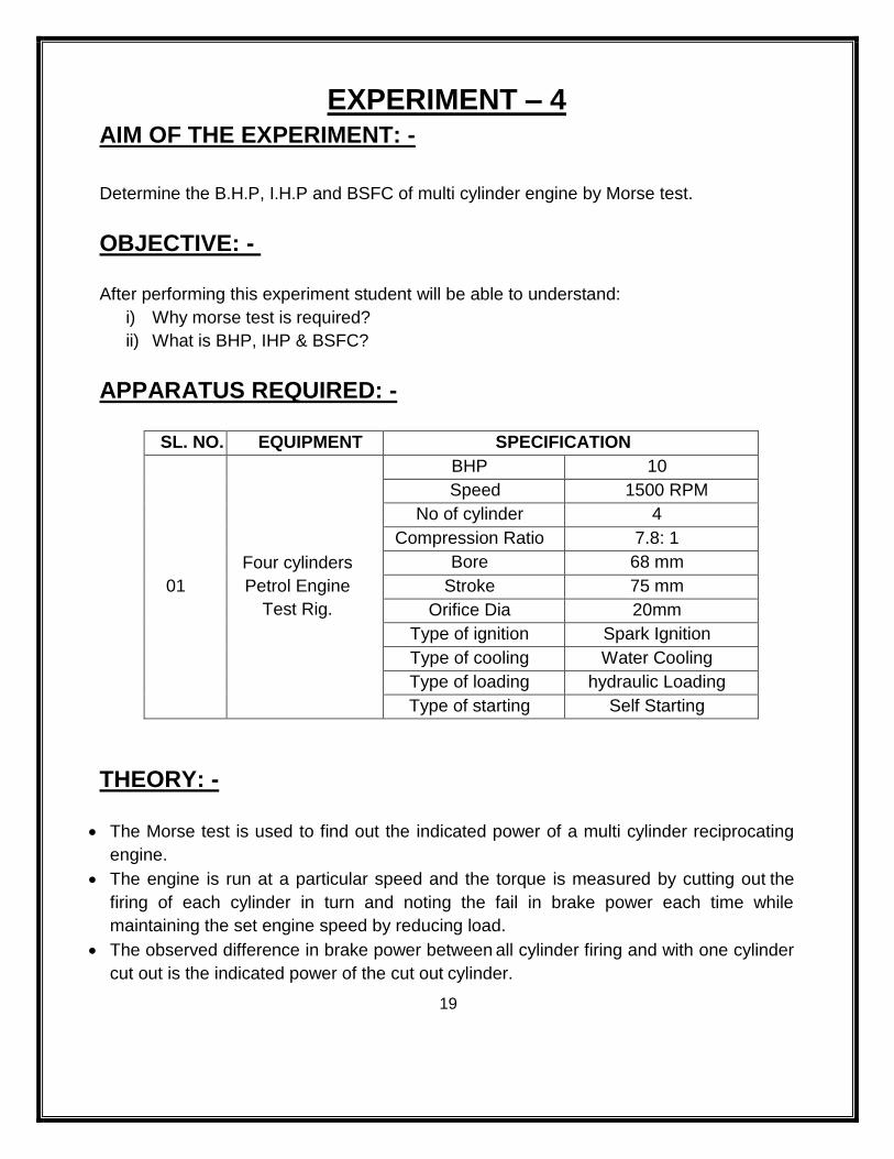
EXPERIMENT – 4 AIM OF THE EXPERIMENT: -
Determine the B.H.P, I.H.P and BSFC of multi cylinder engine by Morse test.
OBJECTIVE: -
After performing this experiment student will be able to understand:
i) Why morse test is required?
ii) What is BHP, IHP & BSFC?
APPARATUS REQUIRED: -
SL. NO. EQUIPMENT SPECIFICATION
01
Four cylinders
Petrol Engine
Test Rig.
BHP 10
Speed 1500 RPM
No of cylinder 4
Compression Ratio 7.8: 1
Bore 68 mm
Stroke 75 mm
Orifice Dia 20mm
Type of ignition Spark Ignition
Type of cooling Water Cooling
Type of loading hydraulic Loading
Type of starting Self Starting
THEORY: -
The Morse test is used to find out the indicated power of a multi cylinder reciprocating
engine.
The engine is run at a particular speed and the torque is measured by cutting out the
firing of each cylinder in turn and noting the fail in brake power each time while
maintaining the set engine speed by reducing load.
The observed difference in brake power between all cylinder firing and with one cylinder
cut out is the indicated power of the cut out cylinder.
20
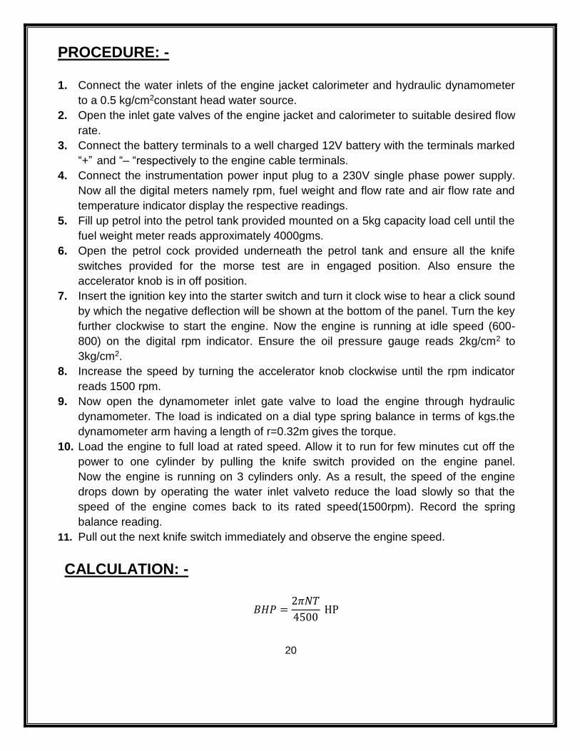
PROCEDURE: -
1. Connect the water inlets of the engine jacket calorimeter and hydraulic dynamometer
to a 0.5 kg/cm2constant head water source.
2. Open the inlet gate valves of the engine jacket and calorimeter to suitable desired flow
rate.
3. Connect the battery terminals to a well charged 12V battery with the terminals marked
“+” and “– “respectively to the engine cable terminals.
4. Connect the instrumentation power input plug to a 230V single phase power supply.
Now all the digital meters namely rpm, fuel weight and flow rate and air flow rate and
temperature indicator display the respective readings.
5. Fill up petrol into the petrol tank provided mounted on a 5kg capacity load cell until the
fuel weight meter reads approximately 4000gms.
6. Open the petrol cock provided underneath the petrol tank and ensure all the knife
switches provided for the morse test are in engaged position. Also ensure the
accelerator knob is in off position.
7. Insert the ignition key into the starter switch and turn it clock wise to hear a click sound
by which the negative deflection will be shown at the bottom of the panel. Turn the key
further clockwise to start the engine. Now the engine is running at idle speed (600-
800) on the digital rpm indicator. Ensure the oil pressure gauge reads 2kg/cm2 to
3kg/cm2.
8. Increase the speed by turning the accelerator knob clockwise until the rpm indicator
reads 1500 rpm.
9. Now open the dynamometer inlet gate valve to load the engine through hydraulic
dynamometer. The load is indicated on a dial type spring balance in terms of kgs.the
dynamometer arm having a length of r=0.32m gives the torque.
10. Load the engine to full load at rated speed. Allow it to run for few minutes cut off the
power to one cylinder by pulling the knife switch provided on the engine panel.
Now the engine is running on 3 cylinders only. As a result, the speed of the engine
drops down by operating the water inlet valveto reduce the load slowly so that the
speed of the engine comes back to its rated speed(1500rpm). Record the spring
balance reading.
11. Pull out the next knife switch immediately and observe the engine speed.
CALCULATION: -
𝐵𝐻𝑃 =2𝜋𝑁𝑇
4500 HP
21
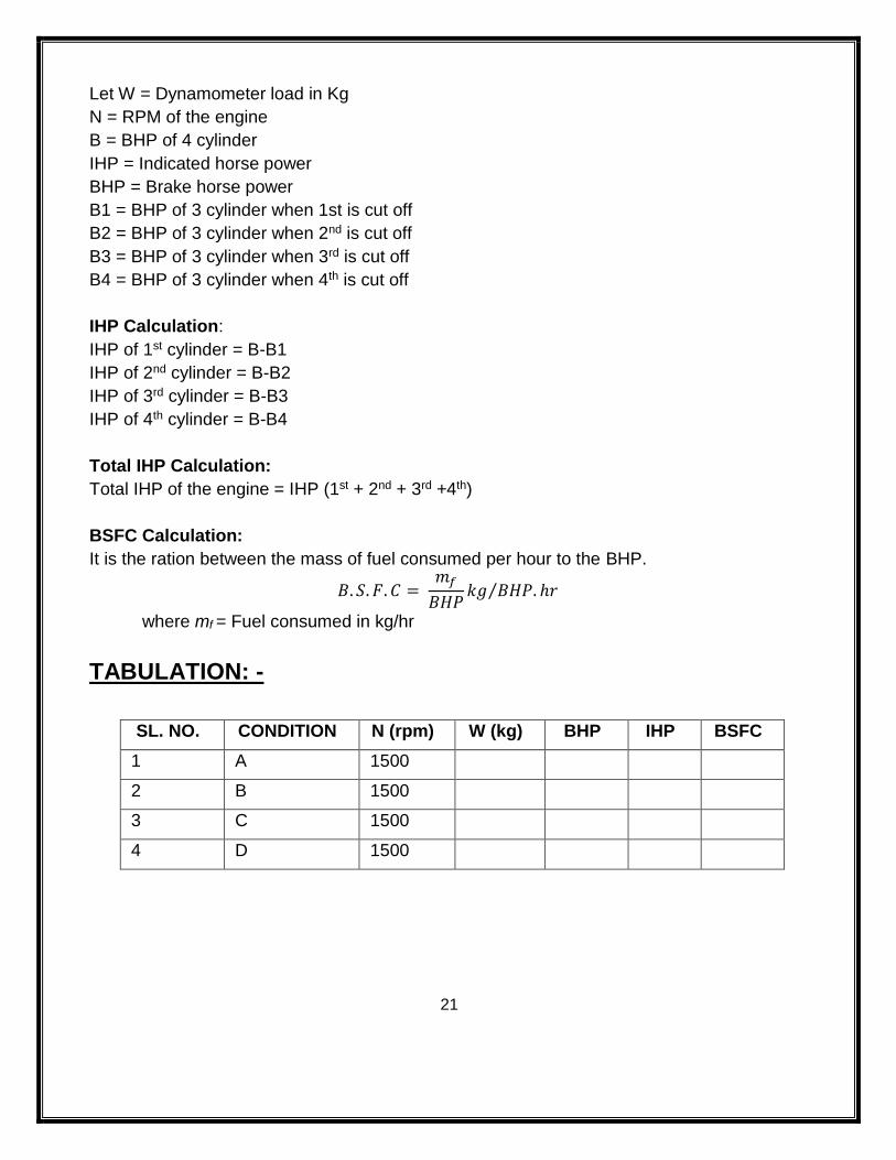
Let W = Dynamometer load in Kg
N = RPM of the engine
B = BHP of 4 cylinder
IHP = Indicated horse power
BHP = Brake horse power
B1 = BHP of 3 cylinder when 1st is cut off
B2 = BHP of 3 cylinder when 2nd is cut off
B3 = BHP of 3 cylinder when 3rd is cut off
B4 = BHP of 3 cylinder when 4th is cut off
IHP Calculation:
IHP of 1st cylinder = B-B1
IHP of 2nd cylinder = B-B2
IHP of 3rd cylinder = B-B3
IHP of 4th cylinder = B-B4
Total IHP Calculation:
Total IHP of the engine = IHP (1st + 2nd + 3rd +4th)
BSFC Calculation:
It is the ration between the mass of fuel consumed per hour to the BHP.
𝐵. 𝑆. 𝐹. 𝐶 = 𝑚𝑓
𝐵𝐻𝑃𝑘𝑔 𝐵𝐻𝑃. ℎ𝑟⁄
where mf = Fuel consumed in kg/hr
TABULATION: -
SL. NO. CONDITION N (rpm) W (kg) BHP IHP BSFC
1 A 1500
2 B 1500
3 C 1500
4 D 1500
22
CONCLUSION: -
The B.H.P, I.H.P and BSFC of multi cylinder engine was found out to be ____________.
POST LAB QUESTIONS: -
i) Define BHP?
ii) Define IHP?
iii) Define BSFC?
iv) What is the purpose of conducting morse test?
23
EXPERIMENT – 5 AIM OF THE EXPERIMENT: -
To determine the mechanical efficiency of a two stage air compressor.
OBJECTIVE: -
After performing this experiment student will be able to understand:
i) About air compressor.
ii) Different components and working of air compressor.
APPARATUS REQUIRED: -
SL.NO. EQUIPMENT SPECIFICATION QUANTITY
01 Air compressor test rig 01
02 Tachometer 01
03 Stop watch 01
THEORY: - An air compressor is the machine which compress the air and to raise its pressure. The air
compressor sucks air from atmosphere, compresses it and then delivers the same under a
high pressure to a storage vessel. From the storage vessel, it may be converged by the pipe
line to a place where the supply of compressed air is required, since the co mpression of air
required some work to be done on it. Therefore, a compressor must be driven by some
prime mover.
CONSTRUCTION: An air compressor consists of the following components:
1. Cylinder
2. Piston
3. Inlet valve
4. Outlet valve
5. Pressure gauge
6. Pressure vessel
24
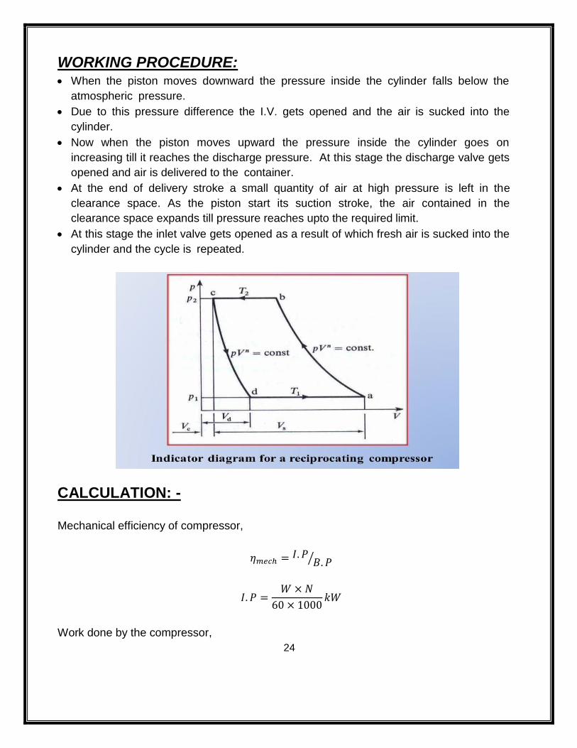
WORKING PROCEDURE: When the piston moves downward the pressure inside the cylinder falls below the
atmospheric pressure.
Due to this pressure difference the I.V. gets opened and the air is sucked into the
cylinder.
Now when the piston moves upward the pressure inside the cylinder goes on
increasing till it reaches the discharge pressure. At this stage the discharge valve gets
opened and air is delivered to the container.
At the end of delivery stroke a small quantity of air at high pressure is left in the
clearance space. As the piston start its suction stroke, the air contained in the
clearance space expands till pressure reaches upto the required limit.
At this stage the inlet valve gets opened as a result of which fresh air is sucked into the
cylinder and the cycle is repeated.
CALCULATION: -
Mechanical efficiency of compressor,
𝜂𝑚𝑒𝑐ℎ = 𝐼. 𝑃𝐵. 𝑃⁄
𝐼. 𝑃 =𝑊 × 𝑁
60 × 1000𝑘𝑊
Work done by the compressor,
25
𝑊 =𝑛
𝑛 − 1𝑚𝑅𝑇1 {(
𝑝2
𝑝1) (
𝑛
𝑛 − 1− 1)}
𝐵. 𝑃 =𝑊 × 𝑁
2000𝑘𝑊
where W = Work done
N = Number of revolution in RPM
P1 = Pressure of air at the inlet of the compressor
P2 = Pressure of the air at the outlett of the compression
T1 = Absolute temp. of air the inlet of the compressor
T2 = Absolute temp. of air the outlet of the compressor
TABULATION: -
SL. NO. P1 P2 T1 T2 I.P B.P MECH EFFICIENCY
1
2
3
CONCLUSION: -
The mechanical efficiency of a two stage air compressor was found to be _____.
PRECAUTION: -
i) Handle the set up carefully.
i) Before Starting the setup check all connections are tight.
ii) Wear safety shoes.
iii) Follow the instructions properly.
POST LAB QUESTION: -
i) What is multistage air compressor?
ii) What is the need of intercooler in air compressor?
iii) Define mechanical efficiency of air compressor?
iv) Draw the P-V diagram of single stage air compressor.
26
EXPERIMENT – 6 AIM OF THE EXPERIMENT: -
Study of pressure measuring devices like Manometer & Bourdon tube pressure gauge.
APPARATUS REQUIRED: -
SL.NO. EQUIPMENT SPECIFICATION QUANTITY
01 Manometer U-tube 01
02 Bourdon tube pressure gauge 01
THEORY: -
MANOMETER:
• A Manometer is slightly improved form of a piezometer tube for measuring high as
well as negative pressure.
• A simple manometer, in its simplest form, consists of a tube bent in U-shape, one
end of which is connected to the vessel containing the liquid whose intensity of
pressure is to be measured and other end is open to the atmosphere.
• The liquid used in the bent tube is generally Mercury (Hg) which is 13.6 times
heavier than water.
• The pressure of the liquid containing in the vessel will force the manometric liquid in
the left hand vertical limb of the U-tube downward and will force the manometric
liquid to rise up in the right hand vertical limb of the U-tube through equal distance.
This will happen when the pressure in the vessel is greater than atmospheric
pressure.
• If pressure of liquid in the vessel is less than atmospheric pressure, the deflection of
manometric liquid will be observed in the left hand limb of the u-tube.
• Since below the surface A-B, the liquid is homogenous and since the liquid is at rest,
the pressure along the plane A-B in the left hand limb of the U-tube is equal to the
pressure in the right hand limb of the U-tube along the plane A-B.
• Then by measuring the difference in mercury level above line A-B, and equating the
pressure at A and pressure at B we can measure pressure of liquid flowing in the
pipe.
27
DIFFERENT TYPES OF MANOMETER:
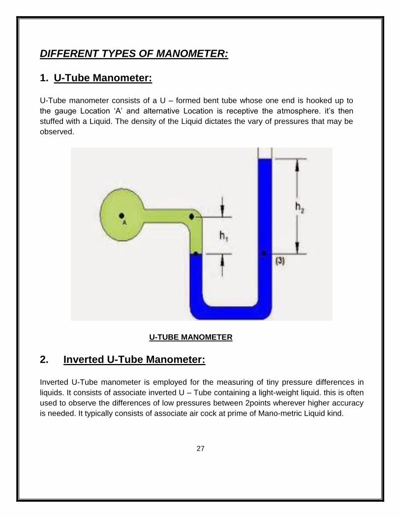
1. U-Tube Manometer:
U-Tube manometer consists of a U – formed bent tube whose one end is hooked up to
the gauge Location ‘A’ and alternative Location is receptive the atmosphere. it’s then
stuffed with a Liquid. The density of the Liquid dictates the vary of pressures that may be
observed.
U-TUBE MANOMETER
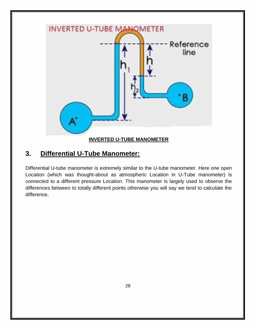
2. Inverted U-Tube Manometer:
Inverted U-Tube manometer is employed for the measuring of tiny pressure differences in
liquids. It consists of associate inverted U – Tube containing a light-weight liquid. this is often
used to observe the differences of low pressures between 2points wherever higher accuracy
is needed. It typically consists of associate air cock at prime of Mano-metric Liquid kind.
28
INVERTED U-TUBE MANOMETER
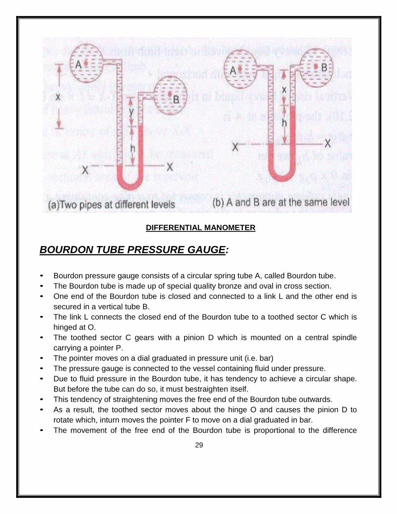
3. Differential U-Tube Manometer:
Differential U-tube manometer is extremely similar to the U-tube manometer. Here one open
Location (which was thought-about as atmospheric Location in U-Tube manometer) is
connected to a different pressure Location. This manometer is largely used to observe the
differences between to totally different points otherwise you will say we tend to calculate the
difference.
29
DIFFERENTIAL MANOMETER
BOURDON TUBE PRESSURE GAUGE:
• Bourdon pressure gauge consists of a circular spring tube A, called Bourdon tube.
• The Bourdon tube is made up of special quality bronze and oval in cross section.
• One end of the Bourdon tube is closed and connected to a link L and the other end is
secured in a vertical tube B.
• The link L connects the closed end of the Bourdon tube to a toothed sector C which is
hinged at O.
• The toothed sector C gears with a pinion D which is mounted on a central spindle
carrying a pointer P.
• The pointer moves on a dial graduated in pressure unit (i.e. bar)
• The pressure gauge is connected to the vessel containing fluid under pressure.
• Due to fluid pressure in the Bourdon tube, it has tendency to achieve a circular shape.
But before the tube can do so, it must bestraighten itself.
• This tendency of straightening moves the free end of the Bourdon tube outwards.
• As a result, the toothed sector moves about the hinge O and causes the pinion D to
rotate which, inturn moves the pointer F to move on a dial graduated in bar.
• The movement of the free end of the Bourdon tube is proportional to the difference
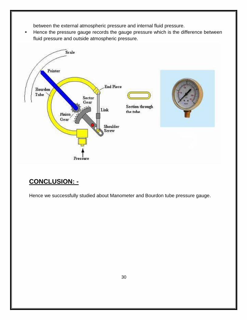
30
between the external atmospheric pressure and internal fluid pressure.
• Hence the pressure gauge records the gauge pressure which is the difference between
fluid pressure and outside atmospheric pressure.
CONCLUSION: -
Hence we successfully studied about Manometer and Bourdon tube pressure gauge.
31
EXPERIMENT – 7 AIM OF THE EXPERIMENT: -
Verification of Bernoulli's theorem.
APPARATUS REQUIRED: -
SL NO EQUIPMENTS SPECIFICATION QUANTITY
01 Bernoullis Apparatus test rig 01
02 Stop watch DIGITAL 01
03 Steel rule 30cm 01
04 Discharge tank 40 cm x 30 cm x 100 cm 01
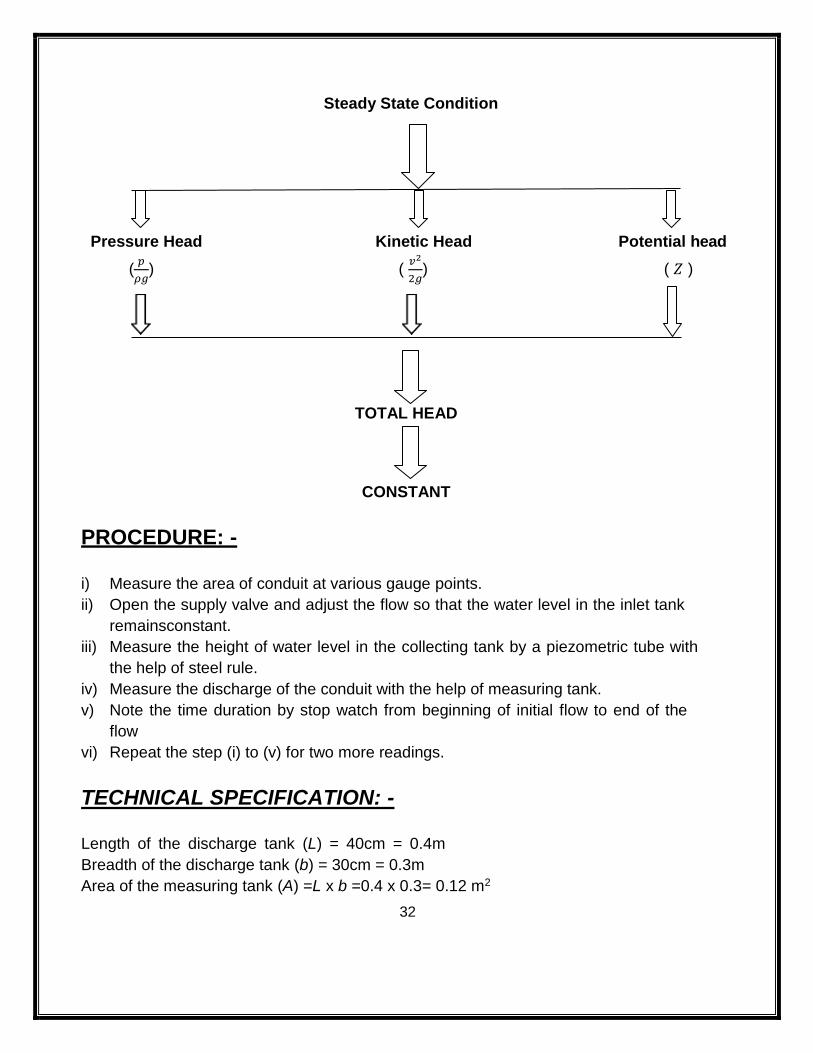
THEORY: -
Bernoulli’s theorem states that “For a steady, continuous, incompressible, &non viscous
fluid flow, the total energy or totalhead remains constant at all the sections along the fluid
flow provided there is no loss oraddition of energy”.
i.e.-
𝑝
𝜌𝑔+
𝑣2
2𝑔+ 𝑍 = 𝐻 = 𝐶𝑜𝑛𝑠𝑡𝑎𝑛𝑡
Where, 𝑝
𝜌𝑔= Pressure head in m
𝑣2
2𝑔 = Velocity or kinetic head in m (Velocity of water =
𝑄
𝐴, m/s)
𝑍 = Potential head (Height above some assumed datum level i.e.- Z=0)
Bernoulli's equation is based on Euler's equation of motion. It is applicable to flow of
fluidthrough pipe and channel. It is required to be modified if the flow is compressible &
unsteady.
CONCEPT STRUCTURE: - The pressure head at every gauge point depends upon the velocity at that cross section.
If the cross sectionarea of the conduit is more the velocity will be less and pressure head
is more.
The valuesof pressure head of the first gauge point is more and subsequently decrease
up to centre ofgauge point. Again the pressure head increases and will form a parabolic
curve.
32
Steady State Condition
Pressure Head Kinetic Head Potential head
(𝑝
𝜌𝑔) (
𝑣2
2𝑔) ( 𝑍 )
TOTAL HEAD
CONSTANT
PROCEDURE: -
i) Measure the area of conduit at various gauge points.
ii) Open the supply valve and adjust the flow so that the water level in the inlet tank
remainsconstant.
iii) Measure the height of water level in the collecting tank by a piezometric tube with
the help of steel rule.
iv) Measure the discharge of the conduit with the help of measuring tank.
v) Note the time duration by stop watch from beginning of initial flow to end of the
flow
vi) Repeat the step (i) to (v) for two more readings.
TECHNICAL SPECIFICATION: -
Length of the discharge tank (L) = 40cm = 0.4m
Breadth of the discharge tank (b) = 30cm = 0.3m
Area of the measuring tank (A) =L x b =0.4 x 0.3= 0.12 m2
33
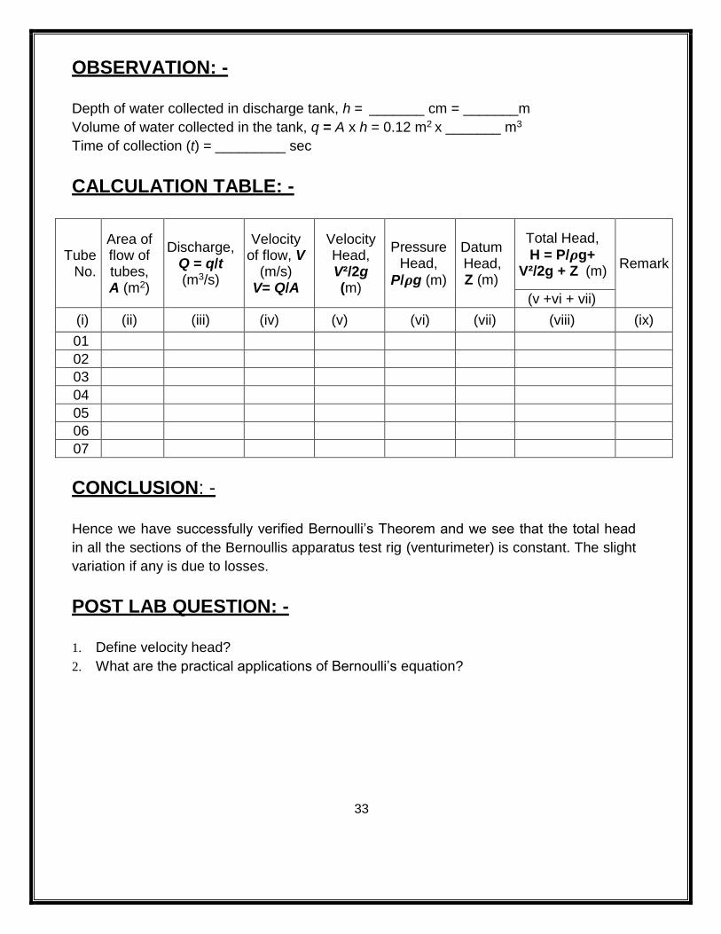
OBSERVATION: -
Depth of water collected in discharge tank, h = _______ cm = _______m
Volume of water collected in the tank, q = A x h = 0.12 m2 x _______ m3
Time of collection (t) = _________ sec
CALCULATION TABLE: -
Tube No.
Area of flow of tubes, A (m2)
Discharge, Q = q/t (m3/s)
Velocity of flow, V
(m/s) V= Q/A
Velocity Head, V²/2g (m)
Pressure Head,
P/𝝆g (m)
Datum Head, Z (m)
Total Head,
H = P/𝝆g+ V²/2g + Z (m)
Remark
(v +vi + vii)
(i) (ii) (iii) (iv) (v) (vi) (vii) (viii) (ix)
01
02
03
04
05
06
07
CONCLUSION: -
Hence we have successfully verified Bernoulli’s Theorem and we see that the total head
in all the sections of the Bernoullis apparatus test rig (venturimeter) is constant. The slight
variation if any is due to losses.
POST LAB QUESTION: -
1. Define velocity head?
2. What are the practical applications of Bernoulli’s equation?
34
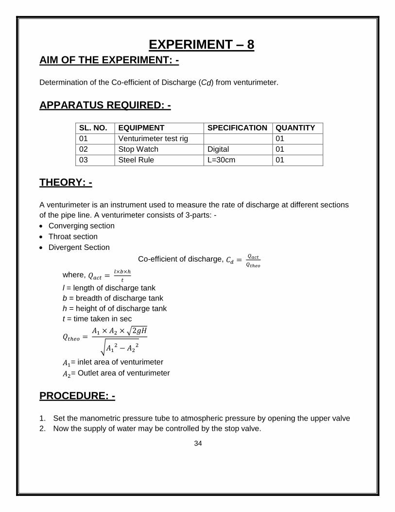
EXPERIMENT – 8 AIM OF THE EXPERIMENT: -
Determination of the Co-efficient of Discharge (Cd) from venturimeter.
APPARATUS REQUIRED: -
SL. NO. EQUIPMENT SPECIFICATION QUANTITY
01 Venturimeter test rig 01
02 Stop Watch Digital 01
03 Steel Rule L=30cm 01
THEORY: -
A venturimeter is an instrument used to measure the rate of discharge at different sections
of the pipe line. A venturimeter consists of 3-parts: -
Converging section
Throat section
Divergent Section
Co-efficient of discharge, 𝐶𝑑 = 𝑄𝑎𝑐𝑡
𝑄𝑡ℎ𝑒𝑜
where, 𝑄𝑎𝑐𝑡 = 𝑙×𝑏×ℎ
𝑡
l = length of discharge tank
b = breadth of discharge tank
h = height of of discharge tank
t = time taken in sec
𝑄𝑡ℎ𝑒𝑜 = 𝐴1 × 𝐴2 × √2𝑔𝐻
√𝐴12 − 𝐴2
2
𝐴1= inlet area of venturimeter
𝐴2= Outlet area of venturimeter
PROCEDURE: -
1. Set the manometric pressure tube to atmospheric pressure by opening the upper valve
2. Now the supply of water may be controlled by the stop valve.
35
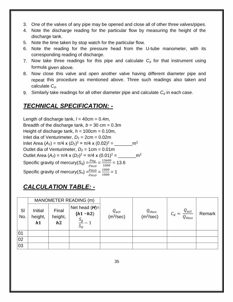
3. One of the valves of any pipe may be opened and close all of other three valves/pipes.
4. Note the discharge reading for the particular flow by measuring the height of the
discharge tank.
5. Note the time taken by stop watch for the particular flow.
6. Note the reading for the pressure head from the U-tube manometer, with its
corresponding reading of discharge.
7. Now take three readings for this pipe and calculate Cd for that instrument using
formula given above.
8. Now close this valve and open another valve having different diameter pipe and
repeat this procedure as mentioned above. Three such readings also taken and
calculate Cd.
9. Similarly take readings for all other diameter pipe and calculate Cd in each case.
TECHNICAL SPECIFICATION: -
Length of discharge tank, l = 40cm = 0.4m,
Breadth of the discharge tank, b = 30 cm = 0.3m
Height of discharge tank, h = 100cm = 0.10m,
Inlet dia of Venturimeter, D1 = 2cm = 0.02m
Inlet Area (A1) = π/4 x (D1)2 = π/4 x (0.02)2 = _______m2
Outlet dia of Venturimeter, D2 = 1cm = 0.01m
Outlet Area (A2) = π/4 x (D2)2 = π/4 x (0.01)2 = _______m2
Specific gravity of mercury(Sg) =𝜌𝐻𝑔
𝜌𝐻2𝑂 =
13600
1000 = 13.6
Specific gravity of mercury(So) =𝜌𝐻2𝑂
𝜌𝐻2𝑂 =
1000
1000 = 1
CALCULATION TABLE: -
Sl
No.
MANOMETER READING (m)
𝑄𝑎𝑐𝑡 (m3/sec)
𝑄𝑡ℎ𝑒𝑜
(m3/sec) 𝐶𝑑 =
𝑄𝑎𝑐𝑡
𝑄𝑡ℎ𝑒𝑜 Remark
Initial
height,
𝒉𝟏
Final
height,
𝒉𝟐
Net head (H)=
(𝒉𝟏 −𝒉𝟐)
𝑆𝑔
𝑆𝑂− 1
01
02
03
36
CONCLUSION: -
From the above experiment, the Co-efficient of Discharge (Cd) of venturimeter was
found out to be ___________. .
37
EXPERIMENT – 9 AIM OF THE EXPERIMENT: -
Determination of the Cc, Cd and Cv from orificemeter.
APPARATUS REQUIRED: -
SL.NO. EQUIPMENT SPECIFICATION QUANTITY
01 Orifice Tank With Piezometer 01
02 Stop Watch Digital 01
03 Collecting Tank 01
THEORY: -
Orifices are devices used for discharging fluids into the atmosphere. It is the opening in
the wall of a tank or in a plate which may be fitted in a pipe such that the plate is normal to
the axis of the pipe. The discharging fluid from the tank/conduit through the orifice comes
out in the form of a free jet. In the process, the total energy of the fluid in the tank is
converted to kinetic energy as the jet issues out into the atmosphere. The jet cross section
initially contracts to a minima and then expands partly due to the viscous resistance
offered by the surrounding atmosphere and partly due to inertia of the fluid particles. The
section which has the minimum area is known as ‘vena contracta’. The contraction and
expansion of the jet results in loss of energy.
The actual velocity at vena contracts is smaller than the theoretical velocity due to
frictional resistances at the orifice edges. The ratio between the actual velocity and the
theoretical velocity of the jet is known as coefficient of velocity Cv. Its value also depends
upon the size and shape of the orifice and the head causing flow. The coefficient velocity
for a vertical orifice is determined experimentally by measuring the horizontal and vertical
coordinates of the issuing jet. The water flows through an orifice under a constant head H.
Let V be the actual velocity (which is horizontal) of the jet. Obviously, while covering
horizontal distance, the jet is acted upon by gravity with a downward acceleration ‘g’.
Consider a small particle of water at vena contracts. Suppose it falls through a vertical
distance ‘y’ in a horizontal distance x, in time t sec.
38
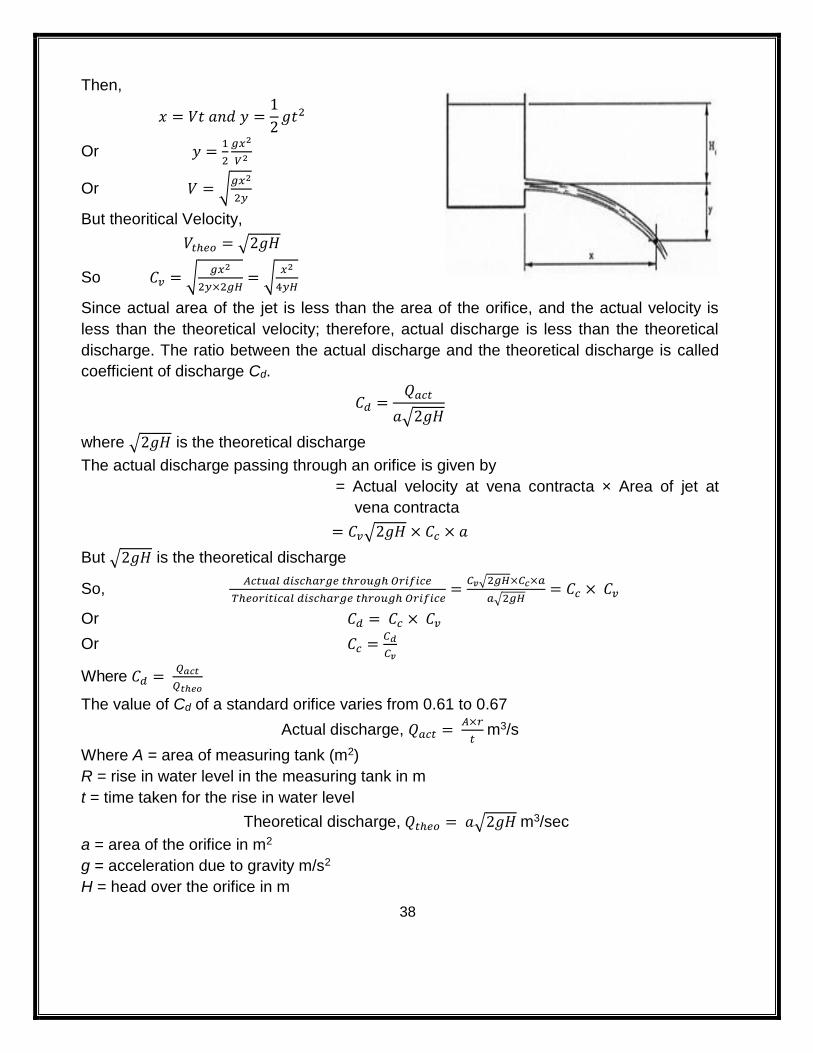
Then,
𝑥 = 𝑉𝑡 𝑎𝑛𝑑 𝑦 =1
2𝑔𝑡2
Or 𝑦 =1
2
𝑔𝑥2
𝑉2
Or 𝑉 = √𝑔𝑥2
2𝑦
But theoritical Velocity,
𝑉𝑡ℎ𝑒𝑜 = √2𝑔𝐻
So 𝐶𝑣 = √𝑔𝑥2
2𝑦×2𝑔𝐻= √
𝑥2
4𝑦𝐻
Since actual area of the jet is less than the area of the orifice, and the actual velocity is
less than the theoretical velocity; therefore, actual discharge is less than the theoretical
discharge. The ratio between the actual discharge and the theoretical discharge is called
coefficient of discharge Cd.
𝐶𝑑 =𝑄𝑎𝑐𝑡
𝑎√2𝑔𝐻
where √2𝑔𝐻 is the theoretical discharge
The actual discharge passing through an orifice is given by
= Actual velocity at vena contracta × Area of jet at
vena contracta
= 𝐶𝑣√2𝑔𝐻 × 𝐶𝑐 × 𝑎
But √2𝑔𝐻 is the theoretical discharge
So, 𝐴𝑐𝑡𝑢𝑎𝑙 𝑑𝑖𝑠𝑐ℎ𝑎𝑟𝑔𝑒 𝑡ℎ𝑟𝑜𝑢𝑔ℎ 𝑂𝑟𝑖𝑓𝑖𝑐𝑒
𝑇ℎ𝑒𝑜𝑟𝑖𝑡𝑖𝑐𝑎𝑙 𝑑𝑖𝑠𝑐ℎ𝑎𝑟𝑔𝑒 𝑡ℎ𝑟𝑜𝑢𝑔ℎ 𝑂𝑟𝑖𝑓𝑖𝑐𝑒=
𝐶𝑣√2𝑔𝐻×𝐶𝑐×𝑎
𝑎√2𝑔𝐻= 𝐶𝑐 × 𝐶𝑣
Or 𝐶𝑑 = 𝐶𝑐 × 𝐶𝑣
Or 𝐶𝑐 =𝐶𝑑
𝐶𝑣
Where 𝐶𝑑 = 𝑄𝑎𝑐𝑡
𝑄𝑡ℎ𝑒𝑜
The value of Cd of a standard orifice varies from 0.61 to 0.67
Actual discharge, 𝑄𝑎𝑐𝑡 = 𝐴×𝑟
𝑡 m3/s
Where A = area of measuring tank (m2)
R = rise in water level in the measuring tank in m
t = time taken for the rise in water level
Theoretical discharge, 𝑄𝑡ℎ𝑒𝑜 = 𝑎√2𝑔𝐻 m3/sec
a = area of the orifice in m2
g = acceleration due to gravity m/s2
H = head over the orifice in m
39
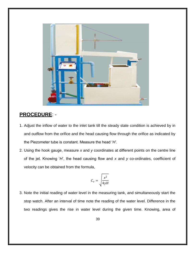
PROCEDURE: -
1. Adjust the inflow of water to the inlet tank till the steady state condition is achieved by in
and outflow from the orifice and the head causing flow through the orifice as indicated by
the Piezometer tube is constant. Measure the head ‘H’.
2. Using the hook gauge, measure x and y coordinates at different points on the centre line
of the jet. Knowing ‘H’, the head causing flow and x and y co-ordinates, coefficient of
velocity can be obtained from the formula,
𝐶𝑣 = √𝑥2
4𝑦𝐻
3. Note the initial reading of water level in the measuring tank, and simultaneously start the
stop watch. After an interval of time note the reading of the water level. Difference in the
two readings gives the rise in water level during the given time. Knowing, area of
40
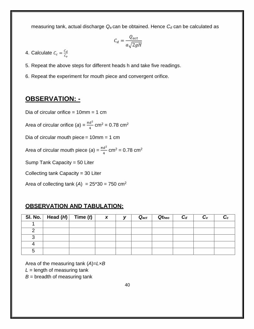
measuring tank, actual discharge Qa can be obtained. Hence Cd can be calculated as
𝐶𝑑 =𝑄𝑎𝑐𝑡
𝑎√2𝑔𝐻
4. Calculate 𝐶𝑐 =𝐶𝑑
𝐶𝑣
5. Repeat the above steps for different heads h and take five readings.
6. Repeat the experiment for mouth piece and convergent orifice.
OBSERVATION: -
Dia of circular orifice = 10mm = 1 cm
Area of circular orifice (a) = 𝜋𝑑2
4 cm2 = 0.78 cm2
Dia of circular mouth piece = 10mm = 1 cm
Area of circular mouth piece (a) = 𝜋𝑑2
4 cm2 = 0.78 cm2
Sump Tank Capacity = 50 Liter
Collecting tank Capacity = 30 Liter
Area of collecting tank (A) = 25*30 = 750 cm2
OBSERVATION AND TABULATION:
Sl. No. Head (H) Time (t) x y Qact Qtheo Cd Cv Cc
1
2
3
4
5
Area of the measuring tank (A)=L×B
L = length of measuring tank
B = breadth of measuring tank
41
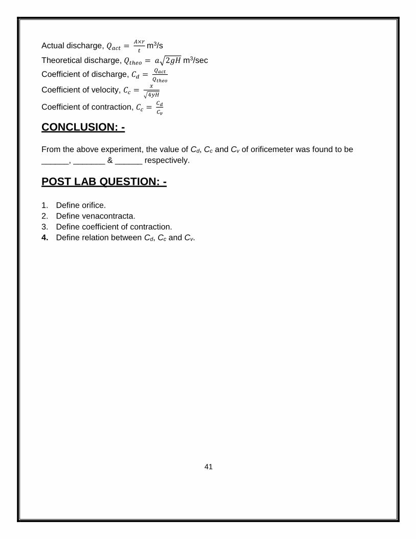
Actual discharge, 𝑄𝑎𝑐𝑡 = 𝐴×𝑟
𝑡 m3/s
Theoretical discharge, 𝑄𝑡ℎ𝑒𝑜 = 𝑎√2𝑔𝐻 m3/sec
Coefficient of discharge, 𝐶𝑑 = 𝑄𝑎𝑐𝑡
𝑄𝑡ℎ𝑒𝑜
Coefficient of velocity, 𝐶𝑐 = 𝑥
√4𝑦𝐻
Coefficient of contraction, 𝐶𝑐 = 𝐶𝑑
𝐶𝑣
CONCLUSION: -
From the above experiment, the value of Cd, Cc and Cv of orificemeter was found to be
______, _______ & ______ respectively.
POST LAB QUESTION: -
1. Define orifice.
2. Define venacontracta.
3. Define coefficient of contraction.
4. Define relation between Cd, Cc and Cv.
42
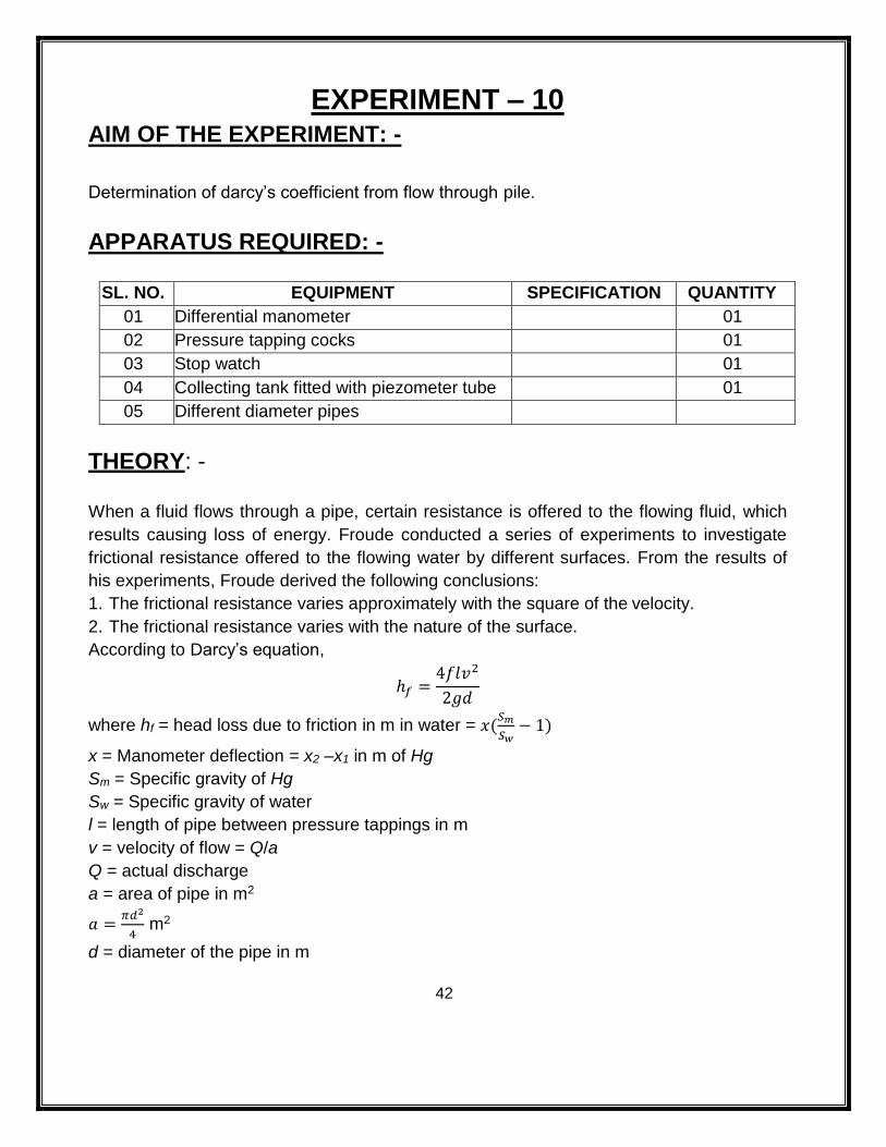
EXPERIMENT – 10 AIM OF THE EXPERIMENT: -
Determination of darcy’s coefficient from flow through pile.
APPARATUS REQUIRED: -
SL. NO. EQUIPMENT SPECIFICATION QUANTITY
01 Differential manometer 01
02 Pressure tapping cocks 01
03 Stop watch 01
04 Collecting tank fitted with piezometer tube 01
05 Different diameter pipes
THEORY: -
When a fluid flows through a pipe, certain resistance is offered to the flowing fluid, which
results causing loss of energy. Froude conducted a series of experiments to investigate
frictional resistance offered to the flowing water by different surfaces. From the results of
his experiments, Froude derived the following conclusions:
1. The frictional resistance varies approximately with the square of the velocity.
2. The frictional resistance varies with the nature of the surface.
According to Darcy’s equation,
ℎ𝑓 =4𝑓𝑙𝑣2
2𝑔𝑑
where hf = head loss due to friction in m in water = 𝑥(𝑆𝑚
𝑆𝑤− 1)
x = Manometer deflection = x2 –x1 in m of Hg
Sm = Specific gravity of Hg
Sw = Specific gravity of water
l = length of pipe between pressure tappings in m
v = velocity of flow = Q/a
Q = actual discharge
a = area of pipe in m2
𝑎 =𝜋𝑑2
4 m2
d = diameter of the pipe in m
43
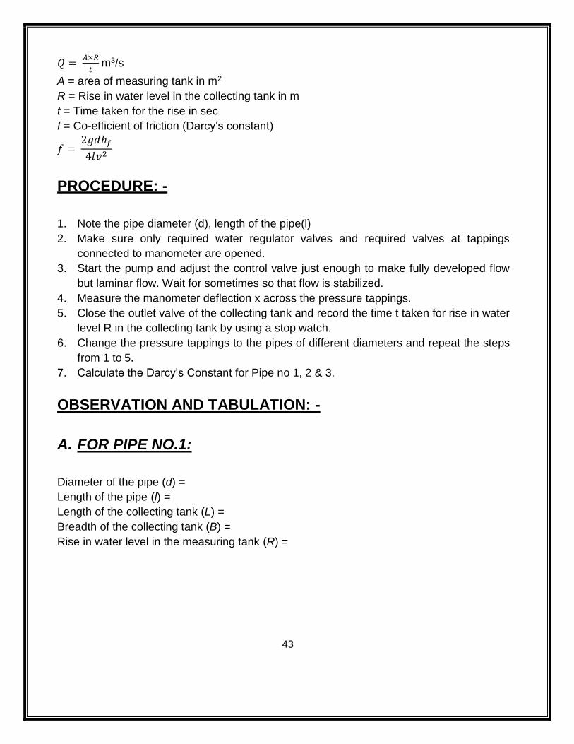
𝑄 = 𝐴×𝑅
𝑡 m3/s
A = area of measuring tank in m2
R = Rise in water level in the collecting tank in m
t = Time taken for the rise in sec
f = Co-efficient of friction (Darcy’s constant)
𝑓 = 2𝑔𝑑ℎ𝑓
4𝑙𝑣2
PROCEDURE: -
1. Note the pipe diameter (d), length of the pipe(l)
2. Make sure only required water regulator valves and required valves at tappings
connected to manometer are opened.
3. Start the pump and adjust the control valve just enough to make fully developed flow
but laminar flow. Wait for sometimes so that flow is stabilized.
4. Measure the manometer deflection x across the pressure tappings.
5. Close the outlet valve of the collecting tank and record the time t taken for rise in water
level R in the collecting tank by using a stop watch.
6. Change the pressure tappings to the pipes of different diameters and repeat the steps
from 1 to 5.
7. Calculate the Darcy’s Constant for Pipe no 1, 2 & 3.
OBSERVATION AND TABULATION: -
A. FOR PIPE NO.1:
Diameter of the pipe (d) =
Length of the pipe (l) =
Length of the collecting tank (L) =
Breadth of the collecting tank (B) =
Rise in water level in the measuring tank (R) =
44
Sl.
No.
Time
(sec)
Manometer readings hf
(m)
Q
(m3/s)
Velocity
(v) (m/s)
Coefficient of
friction (f) X1 X2 x
1
2
3
4
5
6
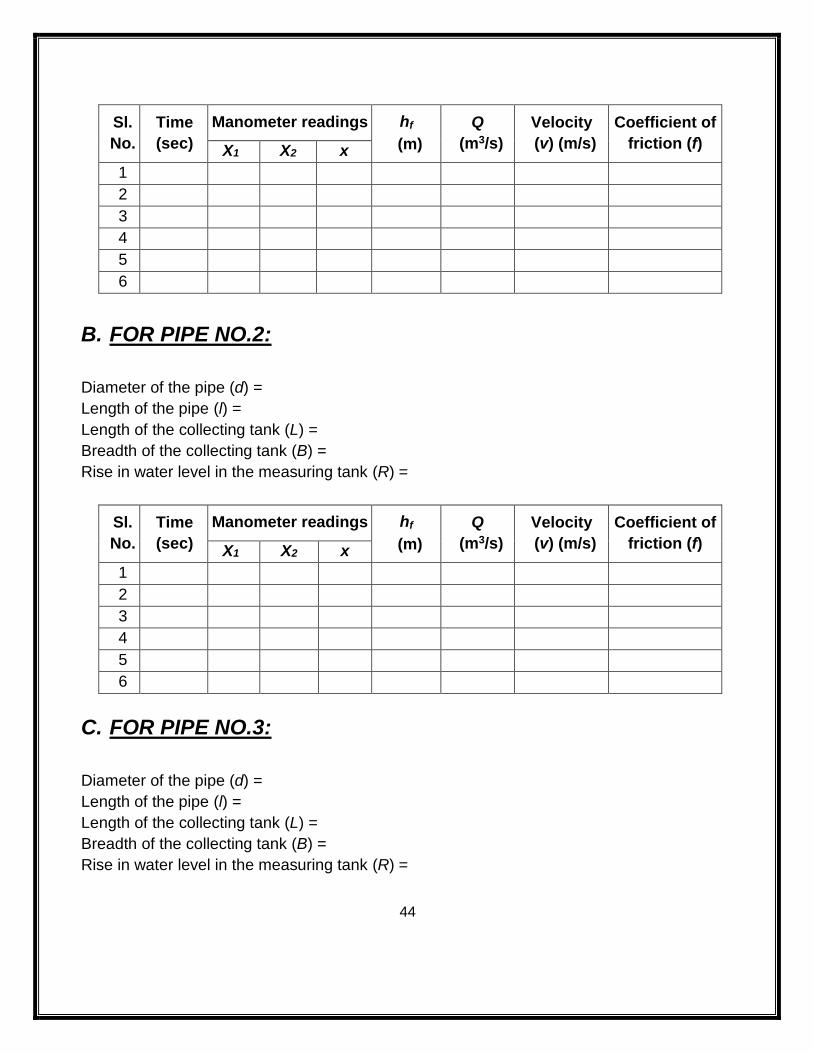
B. FOR PIPE NO.2:
Diameter of the pipe (d) =
Length of the pipe (l) =
Length of the collecting tank (L) =
Breadth of the collecting tank (B) =
Rise in water level in the measuring tank (R) =
Sl.
No.
Time
(sec)
Manometer readings hf
(m)
Q
(m3/s)
Velocity
(v) (m/s)
Coefficient of
friction (f) X1 X2 x
1
2
3
4
5
6
C. FOR PIPE NO.3:
Diameter of the pipe (d) =
Length of the pipe (l) =
Length of the collecting tank (L) =
Breadth of the collecting tank (B) =
Rise in water level in the measuring tank (R) =
45
Sl.
No.
Time
(sec)
Manometer readings hf
(m)
Q
(m3/s)
Velocity
(v) (m/s)
Coefficient of
friction (f) X1 X2 x
1
2
3
4
5
6
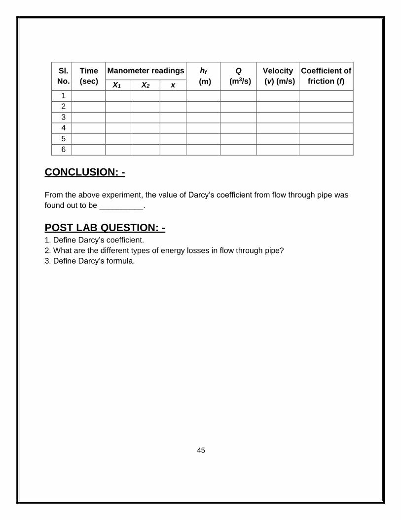
CONCLUSION: -
From the above experiment, the value of Darcy’s coefficient from flow through pipe was
found out to be __________.
POST LAB QUESTION: - 1. Define Darcy’s coefficient.
2. What are the different types of energy losses in flow through pipe?
3. Define Darcy’s formula.

46

47

48

49