mechanical engineering - … · machine design ... a planer mechanism has 10 links and 12 rotary...
TRANSCRIPT


MECHANICAL ENGINEERINGESE TOPICWISE OBJECTIVE SOLVED
PAPER-II
UPSC Engineering Services Examination
State Engineering Service Examination & Public Sector Examination.
FROM (1995-2018)
IES MASTER PUBLICATION Office :Phone : Mobile :E-mail : Web :
F-126, (Lower Basement), Katwaria Sarai, New Delhi-110016 011-26522064, 8130909220, 9711853908 [email protected] www.iesmasterpublications.com

Typeset at : IES Master Publication, New Delhi - 110016
IES MASTER PUBLICATIONF-126, (Lower Basement), Katwaria Sarai, New Delhi-110016Phone : 011-26522064, Mobile : 8130909220, 9711853908E-mail : [email protected] Web : www.iesmasterpublication.org
© No part of this booklet may be reproduced or distributed in any form or by any means, electronic,mechanical, photocopying or otherwise or stored in a database or retrieval system without the priorpermission of IES MASTER PUBLICATION, New Delhi. Violaters are liable to be legally prosecuted.
Second Edition : 2018

Mr. Kanchan Kumar ThakurDirector–IES Master
It is an immense pleasure to present topic wise previous years solved paper of EngineeringServices Exam. This booklet has come out after long observation and detailed interaction withthe students preparing for Engineering Services Exam and includes detailed explanation to allquestions. The approach has been to provide explanation in such a way that just by goingthrough the solutions, students will be able to understand the basic concepts and will applythese concepts in solving other questions that might be asked in future exams.
Engineering Services Exam is a gateway to a immensly satisfying and high exposure job inengineering sector. The exposure to challenges and opportunities of leading the diverse fieldof engineering has been the main reason for students opting for this service as compared toothers. To facilitate selection into these services, availability of arithmetic solution to previousyear paper is the need of the day. Towards this end this book becomes indispensable.
PREFACE

CONTENT
1. Theory of Machines ................................................................................. 01–146
2. Machine Design...................................................................................... 147–256
3. Strength of Materials .............................................................................. 257–400
4. Engineering Materials ............................................................................ 401–469
5. Production Engineering ........................................................................ 470–600
6. Industrial Engineering ........................................................................... 601–711
7. Mechatronics and Robotics ................................................................... 712–717
8. Engineering Mechanics .......................................................................... 718–721


S YL L A BU STypes of Kinematics pair, Mobility, Inversions, Kinematic Analysis, Velocity and Acceleration Analysis of Planarmechanisms, CAMs with uniform acceleration and retardation, cycloidal motion, oscillating followers; Vibrations- Free and forced vibration of undamped and damped SDOF systems, Transmissibility Ratio, Vibration Isolation,Critical Speed of Shafts. Gears - Geometry of tooth profiles, Law of gearing, Involute profile, Interference,Helical, Spiral and Worm Gears, Gear Trains - Simple, compound and Epicyclic; Dynamic Analysis - Slider -crank mechanisms, turning moment computations, balancing of Revolving & Reciprocating masses, Gyroscopes- effect of Gyroscopic couple on automobiles, ships and aircrafts, Governors..
Contents1. Analysis of Planer Mechanism ---------------------------------------------------------------- 01–34
2. Governors and Cam ------------------------------------------------------------------------------ 35–54
3. Slider Crank Mechanism and Flywheel ----------------------------------------------------- 55–67
4. Gear and Gear Trains --------------------------------------------------------------------------- 68–95
5. Balancing ------------------------------------------------------------------------------------------- 96–110
6. Linear Vibration Analysis --------------------------------------------------------------------- 111–138
7. Automatic Control and Whirling of Shafts ----------------------------------------------- 139–146
1

1
IES – 20181. Statement I :
In four-bar chain, whenever all four links areused, with each of them forming a turningpair, there will be continuous relative motionbetween the two links of different lengths.
Statement II :For a four-bar mechanism, the sum of theshortest and longest link lengths is not greaterthan the sum of remaining two links.
2. Consider the following statements:
1. A kinematic chain is the combination ofkinematic pairs joined in such a way thatthe relative motion between them iscompletely constrained.
2. The degree of freedom of a kinematicpai r is given by the number ofindependent coordinates required tocompletely specify the relative movement.
Which of the above statements is/are correct?
(a) 1 only (b) 2 only
(c) Both 1 and 2 (d) Neither 1 nor 2
3. Consider the following statements:
1. Gyroscopic effects generate forces andcouples which act on the vehicles, andthese effects must be taken into accountwhile designing their bearings.
2. Rolling motion of a ship usually occursbecause of the difference in buoyancy on
the two sides of the ship due to a wave.
Which of the above statements is/are correct?
(a) 1 only (b) 2 only
(c) Both 1 and 2 (d) Neither 1 nor 2
IES – 20174. In the 4-bar mechanism as shown, the link PQ
measures 30 cm and rotates uniformly at 100rev/min. The velocity of point Q on link PQ isnearly
50 cm
R
60 cm
SP
Q70 cm
(a) 2.54 m/s (b) 3.14 m/s(c) 4.60 m/s (d) 5.80 m/s
5. Which of the following mechanisms areexamples of forced closed kinematic pairs?1. Cam and roller mechanism2. Door-closing mechanism3. Slider-crank mechanismSelect the correct answer using the code givenbelow.(a) 1 and 2 only (b) 1 and 3 only(c) 2 and 3 only (d) 1, 2 and 3
6. A planer mechanism has 10 links and 12 rotaryjoints. Using Grubler’s criterion, the number ofdegrees of freedom of the mechanism is(a) 1 (b) 3(c) 2 (d) 4
Theory of Machines 3
7. The number of instantaneous centres of rotationin a slider-crank quick return mechanism is(a) 10 (b) 8
(c) 6 (d) 4
IES – 2016
8. Statement (I) : In quick return motionmechanism, Coriolis acceleration exists.
Statement (II) : Two links in this mechanismoscillate with one sliding relative to the other.
9. Consider the following motions :
1. Piston reciprocating inside an enginecylinder
2. Motion of a shaft between foot-stepbearings
Which of the above can rightly be consideredas successfully constrained motion?
(a) 1 only (b) 2 only
(c) Both 1 and 2 (d) Neither 1 nor 2
10. Coriolis component of acceleration depends on
1. angular velocity of the link
2. acceleration of the slider
3. angular acceleration of the link
Which of the above is/are correct?
(a) 1 only (b) 2 only
(c) 1 and 3 (d) 2 and 3
11. In a circular are cam with a roller follower,acceleration of the follower depends on
1. cam speed and location of centre ofcircular arc
2. roller diameter and radius of circular arc
Which of the above is/are correct?(a) 1 only (b) 2 only(c) Both 1 and 2 (d) Neither 1 nor 2
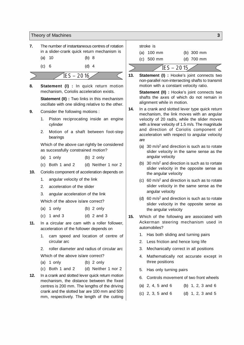
12. In a crank and slotted lever quick return motionmechanism, the distance between the fixedcentres is 200 mm. The lengths of the drivingcrank and the slotted bar are 100 mm and 500mm, respectively. The length of the cutting
stroke is(a) 100 mm (b) 300 mm(c) 500 mm (d) 700 mm
IES – 201513. Statement (I) : Hooke’s joint connects two
non-parallel non-intersecting shafts to transmitmotion with a constant velocity ratio.Statement (II) : Hooke’s joint connects twoshafts the axes of which do not remain inalignment while in motion.
14. In a crank and slotted lever type quick returnmechanism, the link moves with an angularvelocity of 20 rad/s, while the slider moveswith a linear velocity of 1.5 m/s. The magnitudeand direction of Coriolis component ofacceleration with respect to angular velocityare(a) 30 m/s2 and direction is such as to rotate
slider velocity in the same sense as theangular velocity
(b) 30 m/s2 and direction is such as to rortateslider velocity in the opposite sense asthe angular velocity
(c) 60 m/s2 and direction is such as to rotateslider velocity in the same sense as theangular velocity
(d) 60 m/s2 and direction is such as to rotateslider velocity in the opposite sense asthe angular velocity
15. Which of the following are associated withAckerman steering mechanism used inautomobiles?
1. Has both sliding and turning pairs
2. Less friction and hence long life
3. Mechanically correct in all positions
4. Mathematically not accurate except inthree positions
5. Has only turning pairs
6. Controls movement of two front wheels
(a) 2, 4, 5 and 6 (b) 1, 2, 3 and 6
(c) 2, 3, 5 and 6 (d) 1, 2, 3 and 5


Theory of Machines 1 7
1. (c)
2. (c)
3. (c)
4. (b)
5. (a)
6. (b)
7. (c)
8. (c)
9. (b)
10. (a)
11. (c)
12. (c)
13. (d)
14. (c)
15. (a)
16. (b)
17. (b)
18. (a)
19. (a)
20. (d)
21. (b)
22. (b)
23. (d)
24. (c)
25. (a)
26. (c)
27. (d)
28. (c)
29. (a)
30. (b)
31. (c)
32. (b)
33. (a)
34. (c)
35. (d)
36. (c)
37. (c)
38. (c)
39. (c,d)
40. (d)
41. (c)
42. (d)
43. (a)
44. (a)
45. (a)
46. (d)
47. (c)
48. (d)
49. (a)
50. (a)
51. (d)
52. (b)
53. (a)
54. (b)
55. (c)
56. (a)
57. (d)
58. (c)
59. (a)
60. (c)
61. (a)
52. (d)
63. (d)
64. (b)
65. (a)
66. (d)
67. (c)
68. (a)
69. (d)
70. (d)
71. (b)
72. (c)
73. (a)
74. (b)
75. (a)
76. (a)
77. (b)
78. (c)
79. (a)
80. (c)
81. (d)
82. (c)
83. (b)
84. (a)
85. (b)
86. (c)
87. (d)
88. (d)
89. (c)
90. (a)
91. (b)
92. (**)
93. (a)
94. (d)
95. (c)
96. (b)
97. (c)
98. (a)
99. (a)
100. (d)
101. (a)
102. (c)
103. (c)
104. (c)
105. (a)
1 8 ESE Topicwise Objective Solved Paper-II 1995-2018
Sol–1 (c)
For a four bar mechanism to form, sum ofthree links should be more than longestlink. For inversion purpose, the sum oflargest and smallest should be less thanthe rest two.
Sol–2 (c)A kinematic chain is the combintion ofkinematic pairs joined in such a way thateach link forms a part of two pairs and therelative motion between the l inks iscompletely or successfully constrained.
The degreee of freedom of a kinematic pairis given by the number of independentcoordinates required to completely specifythe relative movement.
Sol–3:(c)Rolling motion usually occurs because ofthe difference in buoyancy on the two sidesof a ship due to a wave. This is a periodiccouple and has a maximum value when theship is on either side of the wave at thepoint of maximum slope and zero when theship is at a peak or in the trough of thewave.
The gyroscopic effects generates forces andcouples which act on the vehicles and othermeans of transport like ships, aeroplanesetc. These effects must be taken intoaccount while designing them especially inselection of bearings etc.
Sol–4: (b)The angular velocity of link PQ,
=2 N 2 100 rad/sec60 60
Velocity of point Q on link PQ,
V = 2 100PQ 0.3060
= 3.14 m/sec
Sol–5: (a)Forced closed mechanism require externalforce to maintain mechanical contactbetween links. Slider-crank mechanismdoes not requires such force.
Sol–6: (b)Degree of freedom using grubler criterion,
DoF = 3 (n – 1) – 2J – h – Fr
= 3 (10 –1)–2×12 – 0 – 0 = 3Sol–7: (c)
No of instantaneous centre,
= n 42 2
4 3C C 62
Sol–8: (c)In quick return mechanism, slider moveson oscilating/rotating link, so Coriolisacceleration exist. But in this mechanism,one link rotates and other oscillates andslider a third link slides.
Sol–9: (b)Successfully constraint motion means thatthe motion is constraint only in the presenceof external force. The piston inside cylinderexecutes constraint motion due to it designand gudgeon pin. While foot step bearingrequires a force to press the shaft in bearingto have constraint motion (rotation).
Sol–10: (a)The expression for Coriolis component ofacceleration,= 2 V
where V is sliding velocity of slider overoscillating link and ‘ ’ is angular velocityof osci l l at ing l ink in qui ck returnmechanism.
Sol–11: (c)The expression for acceleration of followerinvolve following parameters(i) Radius of flank of cam surface, ‘rf’
Theory of Machines 1 9
(ii) Least radius of cam profile or basecircle radius ‘rb’.
(iii) Radius of roller ‘rr’.(iv) Cam rotation speed ' '
Sol–12: (c)Driving crank length
O1A = 100 mmSlotted Bar length
O2B = 500 mm
In triangle O2O,A
sin = 1
1 2
O A 100O O 200
= 30°
O1
A
200m
m
O2
C B
Length of cutting stroke,
= 22BC 2O Bsin 2 500 sin30
= 2 × 500 × 0.5 = 500 mmSol–13: (d)
The Hooke’s joint connects two non-parallelshafts but intersecting. For constant velocityratio there are two Hooke’s joints inparticular torks orientation
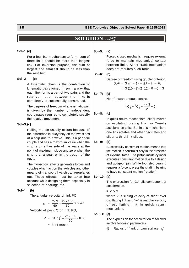
Sol–14: (c)The schematic of quick return mechanism
V
C 2V
The Coriolis acceleration,
ac = 2V = 2 × 1.5 × 20= 60 m/sec2
Direction: The direction of Coriol iscomponent of acceleration depends uponvelocity of slider ‘C’. If slider moves awayfrom centre, the Coriolis acceleration willbe in the direction of link rotation. If theslider moves toward centre of rotation theCoriolis acceleration will be opposite to linkrotation as shown below.
V
C
A
C
A
2V2V
V
Since nothing is mentioned about velocityof slider (away or toward centre) so assumeit moves away from centre, the right.
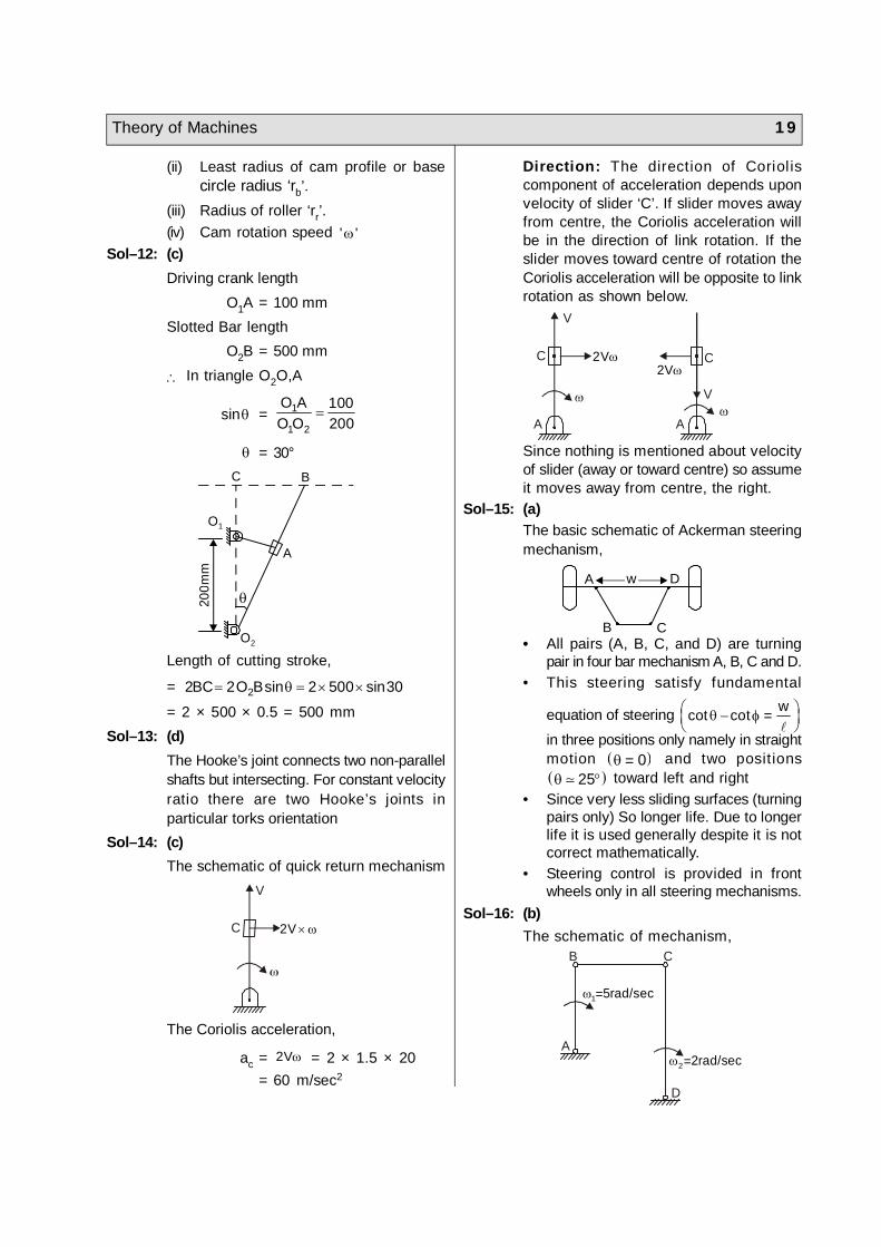
Sol–15: (a)The basic schematic of Ackerman steeringmechanism,
A w D
B C• All pairs (A, B, C, and D) are turning
pair in four bar mechanism A, B, C and D.• This steering satisfy fundamental
equation of steering =
wcot cot
in three positions only namely in straightmotion 0 = and two positions 25 toward left and right
• Since very less sliding surfaces (turningpairs only) So longer life. Due to longerlife it is used generally despite it is notcorrect mathematically.
• Steering control is provided in frontwheels only in all steering mechanisms.
Sol–16: (b)The schematic of mechanism,
B C
A
D
1 5rad/sec=
2 2rad/sec=