mechanical estimating manual - iqytechnicalcollege.com 690-mechanical estimating.pdf · mechanical...
TRANSCRIPT


Mechanical Estimating Manual
Sheet Metal, Piping and Plumbing

This page intentionally left blank
Mechanical Estimating Manual
Sheet Metal, Piping and Plumbing
By Wendes Systems, Inc.
Edited by Joseph D’Amelio

iv
Library of Congress Cataloging-in-Publication Data
Mechanical estimating manual : sheet metal, piping, and plumbing/by Wendes Systems, Inc.;
edited by Joseph D’Amelio.
p. cm.
Includes index.
ISBN 0-88173-538-8 (print) -- ISBN 0-88173-539-6 (electronic)
1. Buildings--Mechanical equipment--Installation--Estimates--Handbooks,
manuals, etc. I. D’Amelio, Joseph . II. Wendes Systems, Inc.
TH6010.M457 2006
696--dc22
2006041262
Mechanical estimating manual : sheet metal, piping, and plumbing/by Wendes Systems, Inc.; edited by Joseph
D’Amelio
©2007 by The Fairmont Press, Inc. All rights reserved. No part of this publication may be reproduced
or transmitted in any form or by any means, electronic or mechanical, including photocopy,
recording, or any information storage and retrieval system, without permission in writing from the
publisher.
Published by The Fairmont Press, Inc.700 Indian TrailLilburn, GA 30047tel: 770-925-9388; fax: 770-381-9865http://www.fairmontpress.com
Distributed by Taylor & Francis Ltd.6000 Broken Sound Parkway NW, Suite 300Boca Raton, FL 33487, USAE-mail: [email protected]
Distributed by Taylor & Francis Ltd.23-25 Blades CourtDeodar RoadLondon SW15 2NU, UKE-mail: [email protected]
Printed in the United States of America10 9 8 7 6 5 4 3 2 1
0-88173-505-1 (The Fairmont Press, Inc.)
0-8493-9210-1 (Taylor & Francis Ltd.)
While every effort is made to provide dependable information, the publisher, authors, and editors
cannot be held responsible for any errors or omissions.

v
Quick ReferenceSection I—HOW TO PREPARE SHEET METAL AND PIPING ESTIMATES 1 Wendes Guide to Successful Estimating; Principles 2 Systematic and Effi cient Estimating Procedures 3 Sample HVAC Estimate and Forms
Section II—BUDGET ESTIMATING 4 Budget Estimating
Section III—EQUIPMENT ESTIMATING 5 Heating and Cooling Equipment 6 HVAC Units and Air Distribution Equipment 7 Plumbing Fixtures and Specialties 8 Air Pollution and Heat Recovery Equipment
Section IV —SHEET METAL ESTIMATING 9 Sheet Metal Estimating Basics 10 Rectangular Galvanized Ductwork 11 Spiral and Light Gauge Round Ductwork. 12 Fiber Glass Ductwork 13 Heavy Gauge Ductwork. 14 Sheet Metal Specialties and Acoustical Lining 15 Miscellaneous Labor Operations
Section V—PIPING ESTIMATING 16 Piping Estimating Basics 17 Pressure Pipe and Fittings 18 Valves and Specialties 19 DNVV Pipe and Fittings
Section VI—CONTRACTING FOR PROFIT 20 Markups for Overhead and Profi t 21 Contracting for profi t 22 Computerized Estimating

This page intentionally left blank
vii
Contents
Preface ............................................................................................................................................................ xi
Section I—HOW TO PREPARE SHEET METAL AND PIPING ESTIMATES
Chapter 1 Successful Estimating Principles .................................................................................................. 3 Crux of Successful Contracting ....................................................................................................... 3 Primary Goals of Contracting and Bidding .................................................................................. 3 Problems and Causes of Poor Estimating ...................................................................................... 3 Estimating Competence Required .................................................................................................. 4 The Eight Facets of the Estimating Diamond ............................................................................... 4 Performance Standards for Complete and Accurate Estimates ................................................. 5 Fundamental Bidding Rules ............................................................................................................ 5 How to Estimate Labor Accurately and Realistically .................................................................. 8 Do Your Homework .......................................................................................................................... 9 Use Time Saving Estimating Techniques ....................................................................................... 9 Apply Valid Overhead and Profi t Markups ................................................................................ 10
2 Systematic, Effi cient, Accurate Estimating Procedures ...........................................................11 Steps in the Estimating Procedure .................................................................................................11 Checking Estimates ........................................................................................................................ 12 Scope of Complete Sheet Metal Estimate, Check-off List ......................................................... 16 Heating Equipment Check-off List ............................................................................................... 17 Cooling Equipment Check-off List ............................................................................................... 18 End of Bid Factors Check-off List ................................................................................................. 18 Remodeling Work Check-off List .................................................................................................. 19 15 Bastards with No Regular Homes ........................................................................................... 20
3 Sample HVAC Estimate and Forms ............................................................................................ 23 Overview of Sample Job ................................................................................................................. 23 Purpose of Forms ............................................................................................................................ 23 Specifi cations on Sample Job ......................................................................................................... 24 IBM Offi ce Drawing ........................................................................................................................ 25 Sample Filled Out Estimating Forms ........................................................................................... 26 Calculating Labor Costs Per Hour ................................................................................................ 31
Section II —BUDGET ESTIMATINGChapter 4 Budget Estimating .......................................................................................................................... 37 Budget Estimates ............................................................................................................................. 37 Semi-Detailed Scope Budget Estimates ....................................................................................... 37 Detailed Estimates .......................................................................................................................... 38 Budget Estimating HVAC Costs and Engineering Loads ......................................................... 38 Budget Estimating Galvanized Ductwork .................................................................................. 39
Section III —EQUIPMENT ESTIMATINGChapter 5 Heating and Cooling Equipment ................................................................................................ 59 Chilled and Hot Water Pumps ...................................................................................................... 60

viii
Hot Water Reheat Coils .................................................................................................................. 61 Electric Duct Heaters ...................................................................................................................... 62 Duct Heaters .................................................................................................................................... 63 Unit Heaters ..................................................................................................................................... 63 Gas Fired Cast Iron Boilers ............................................................................................................ 64 Baseboard Heating .......................................................................................................................... 65 Infra Red Units ................................................................................................................................ 66 Electric Baseboard Heating ............................................................................................................ 66 Wall Heaters ..................................................................................................................................... 67 DX Evaporator Coils ....................................................................................................................... 68 Chilled Water Coils ......................................................................................................................... 69 Centrifugal Water Cooled Chillers ............................................................................................... 70 Reciprocating Chillers .................................................................................................................... 71 Cooling Towers ................................................................................................................................ 73 Heat Pumps ..................................................................................................................................... 74 Condensing Units ........................................................................................................................... 75
6 HVAC Units and Air Distribution Equipment ........................................................................ 77 Rooftop Units ................................................................................................................................... 78 Air Handling Units ......................................................................................................................... 80 Self Contained Air Conditioning Units ........................................................................................ 83 Dampers ........................................................................................................................................... 87 Louvers ............................................................................................................................................. 89 Estimating Registers ....................................................................................................................... 90 Ceiling Diffusers .............................................................................................................................. 91 VAV Terminal Units, Components etc. ........................................................................................ 92 Filter Labor ....................................................................................................................................... 96
7 Plumbing Fixtures and Specialties ............................................................................................. 97
8 Air Pollution and Heat Recovery Equipment ......................................................................... 101 Air pollution equipment .............................................................................................................. 101
Section IV— SHEET METAL ESTIMATINGChapter 9 Sheet Metal Estimating Basics ................................................................................................... 109 Requirements of a Profi cient Sheet Metal Estimator ............................................................... 109 Types of Ductwork .........................................................................................................................111 Procedure for Taking Off Ductwork ............................................................................................112 Types of Ductwork Connections ..................................................................................................113 Methods of Figuring Ductwork Weight ......................................................................................114 Methods of Calculating Ductwork Labor ..................................................................................115 Material Data ................................................................................................................................. 124 Correction Factors ......................................................................................................................... 125
10 Galvanized Ductwork ................................................................................................................. 129 Estimating Galvanized Ductwork by the Piece ........................................................................ 129 Estimating Galvanized Ductwork by the Pound ..................................................................... 136 Medium and High Pressure Ductwork ..................................................................................... 142 Automatic Duct Coil Line Fabrication ....................................................................................... 143

ix
11 Spiral and Light Gauge Round Ductwork .............................................................................. 145 Round Duct Gauge Data .............................................................................................................. 146 Furnace Pipe Flexible Tubing and Flues .................................................................................... 146 Spiral Pipe and Fittings ................................................................................................................ 147
12 Estimating Fiberglass Ductwork ............................................................................................... 155 Introduction ................................................................................................................................... 155 Fiberglass Ductwork Construction ............................................................................................. 156 Pricing Sheet Metal Components ............................................................................................... 158 Estimate Summary and Extension Sheet .................................................................................. 158
13 Heavy Gauge Ductwork ............................................................................................................. 159 Types of Industrial Exhaust Ductwork ...................................................................................... 159 Rectangular Black Iron ................................................................................................................. 159 Round Black Iron Ductwork ........................................................................................................ 166 Rolled Steel Angle Rings .............................................................................................................. 171 Example of Round Black Iron ..................................................................................................... 172 Aluminum ...................................................................................................................................... 173 Stainless Steel ................................................................................................................................. 175 FRP Ductwork ............................................................................................................................... 177 FRP Coated Galvanized Ductwork ............................................................................................ 179 Labor Multipliers for Heavy Gauge Ductwork ........................................................................ 180 Air Pollution Estimating .............................................................................................................. 180
14 Sheet Metal Specialties and Acoustical Lining ...................................................................... 187 Access Doors, Belt Guards, Drain Pans ..................................................................................... 187 Flexible Connections, Hoods, Stands and Platforms ............................................................... 188 Roof Hoods .................................................................................................................................... 189 Turning Vanes ................................................................................................................................ 190 Splitter Dampers ........................................................................................................................... 191 Sheet Metal Housings ................................................................................................................... 192 Acoustic Lining ............................................................................................................................. 192
15 Miscellaneous Labor Operations .............................................................................................. 195 Drafting and Sketching Labor ..................................................................................................... 195 Field Measuring and Sketching Labor ....................................................................................... 196 Estimating Air Testing and Balancing ........................................................................................ 196 Estimating Ductwork Leak Testing ............................................................................................ 199
Section V —PIPING ESTIMATINGChapter 16 Piping Estimating Basics ............................................................................................................ 203 Requirements of a Profi cient Piping Estimator ........................................................................ 203 Sample Estimate ............................................................................................................................ 207
17 Pressure Pipe, Fittings and Insulation ..................................................................................... 217 Pressure Piping and Fittings Tables for Threaded, Welded, Flanged, Grooved and Associated Labor ................................................ 218 Copper Tubing, L, K, K Labor and Pricing etc. ......................................................................... 236
18 Valves and Specialties ................................................................................................................. 253

x
Bronze #125, #150 Valves ............................................................................................................. 254 Iron #125, #150 Valves .................................................................................................................. 256 Specialty Valves ............................................................................................................................. 260
19 DWV Pipe and Fittings ............................................................................................................... 271 Copper Tubing, DWV ................................................................................................................... 272 PVC DWV Schedule 40 ................................................................................................................ 274 ABS DWV ....................................................................................................................................... 278 Cast Iron Hub and Spigot DWV ................................................................................................. 280
Section VI—CONTRACTING FOR PROFITChapter 20 Markups for Overhead and Profi t ............................................................................................. 287 Understanding and Applying Correct Overhead and Profi t Factors .................................... 287
21 Contracting for Profi t ................................................................................................................... 295 What Determines Your Profi tability ........................................................................................... 295 How to Legitimately Reduce Costs on a Bid ............................................................................ 296 Star Method of Reducing Ductwork and Piping Costs ........................................................... 297
22 Computerized Estimating ........................................................................................................... 305

xi
This cost estimating manual, covering labor and material costs for sheet metal, piping and plumbing construction work, will save you time and money, and help get you jobs. It is a clear, practical, comprehensive mechanical estimating manual, with a tremendous source of valid labor and price data, formulas, charts, graphs, etc. It covers proven methodology, effi cient procedures, all types of practical forms, detailed estimating, budget estimating, and has many sample estimates. It shows you how to produce complete and accurate sheet metal, piping and plumbing estimates quickly and easily. It contains complete man hours, material costs and budget costs. It is clear, concise, comprehensive and clearly organized for easy reference and application to smooth estimating. It is an indispensable guide and source of data for the various aspects of mechanical estimating, used by contractors, estimators, owners, and anyone involved with estimating mechanical costs on construction projects. It also is a great aid to supervisors, mechanics, builders, general contractors, engineers, and architects for planning and scheduling work, budget estimating, cost control, cost accounting, checking change orders, etc.
The Mechanical Estimating Manual covers:
• The principles of successful estimating and contracting, systematic estimating procedures and sample estimates.
• It covers conceptual and scope budget estimating, as well as fully detailed.
• It covers estimating all types of mechanical equipment; heating and cooling, HVAC units, air distribution, plumbing fi xtures, specialties, air pollution and heat recovery equipment.
• It covers estimating all types of sheet metal, pressure pipe and fi ttings, DWV pipe and fi ttings, valves, specialties, etc.
• It covers contracting for profi t, how to correctly applied overhead and profi t markups to bids, how to reduce costs to get jobs, computerized estimating, etc.
Preface
Great Need for Valid Labor Figures There has been a great need for complete and valid man-hour fi gures on ductwork put together in a practical fashion. Here is a manual that does just that. And combined with complete and valid piping and plumbing labor and cost fi gures, it thoroughly covers the entire realm of mechanical contracting estimating.
Based on Twenty Years of Cost Records and Time Studies The sheet metal labor fi gures contained herein span over twenty years of cost records, labor histories and time studies, not only from the contracting company the author was with during that time period, but also through feedback and verifi cations from other contractors all over the United States and Canada through seminars, consultation and the Wendes estimating system.
Optimal Estimating Labor by the Piece or the Pound Estimating galvanized ductwork by the piece was a major undertaking of countless time studies, cost records and labor histories. The time per piece for different sizes and types of ductwork was desperately needed data by the sheet metal industry for decades. It is now fully developed and verifi ed. However, for those that still prefer per pound estimating for sheet metal—both per pound and per piece methods are completely and thoroughly covered herein.
Piping Labor Tables The piping tables contain valid labor fi gures which are a consensus of leading successful piping contractors all over the U.S., both large and small—developed and compiled during the past ten years with Wendes Systems piping estimating software owners.
Widespread Application of Manual If you are a contractor or estimator the manual can improve your estimating accuracy, reduce the time spent estimating, aid you in selective bidding and can help get you more jobs. If you are the owner of a contracting company or manager of the estimating department, this manual will serve as your set of company standards. The data herein can be adjusted as may be required, to meet your particular productivity rates more precisely. The manual can be used for training and controlling of estimating

xii
personnel operations. If you are a project manager, superintendent, foreman or mechanic, here is as excellent guide for planning, scheduling, and monitoring work. If you are an engineer, architect, builder or general contractor, this manual will clarify what is all involved in mechanical pricing, and give you quick and accurate budget prices, as well for checking change orders.
Man Hour Labor Tables The key to estimating labor correctly in the sheet metal and piping industries is to work with man hours rather than dollar costs. Labor is more accurately measured in hours and is more of a constant than dollars. Only after the labor hours are derived for an estimate should they be converted in dollars. Hence, this manual works with man hours productivity rates, which can more directly related to, than dollar fi gures-by anyone anywhere, at any time, today and next year etc., thus by passing all the different wage rates in the country, the various union and non-union rates and the continual adjustments for wage increases, infl ation etc.
Labor Based on Typical Average Mechanic The labor times recorded in this manual are what the average mechanic, of average competence and training, under average conditions, with typical equipment and
tools, with normal motivation and supervision, should be able to do and must in today’s market. Where conditions and personnel vary from the typical situation, labor correction factors should be applied. Equipment prices, rentals, budget fi gures, materials, sub-contractors, etc., are of course, in dollar fi gures.
Labor Tables Priceless Since it takes endless years of actual experience, a host of different projects, costly trial and error, a great deal of time, effort, analysis and money to fi nally reach concrete, valid labor times for the infi nite variety of work involved in mechanical work, the labor tables in the manual can, indeed, be priceless to contractors, estimators, engineers, etc.
Manual Directly Applicable to Wendes WinDuct and WinPipe Estimating Systems Labor tables, price tables, material data, procedures, formulas, etc., all correlate with the Wendes WinDuct and WinPipe estimating systems. This manual gives an overall perspective and detailed understanding of the estimating systems and contractors can switch from manual estimating using this manual to the computer estimating system quickly and easily.

Section I
How to Prepare Sheet Metal and
Piping Estimates

This page intentionally left blank

3
THE CRUX OF SUCCESSFUL CONTRACTING
Successful contracting is built on a foundation of complete and accurate estimates with valid markups for overhead and profi t. That means bids must cover the direct costs of labor, mate-rial, equipment and subcontractors, plus the indirect overhead costs of the company as well as providing some profi t.
PRIMARY GOALS OF CONTRACTING AND BIDDING
The primary goal of an estimate is to cover all costs as they probably will occur when the job is completed, while still having a reasonable chance of getting the job and of being able to meet acceptable plan, spec and per-formance criteria.
The primary goal of a markup for overhead costs on bids is to cover the total of the overhead expenditures for the year, and that all the projects contribute their pro-portionate shares.
The primary goal of a markup for profi t is to pro-vide money for capital investments, a return on the cor-porate investments and as a reward for the hard work and risks. If you can’t end up with suffi cient earnings on investments commensurate with the burden of contract-ing, then it might be advisable to put the money into CD’s or bonds and take it easy.
The primary goal of contracting is to make money, not lose it. It is not just to keep the company going some way or the other, or keep a lot of people employed. Preparing complete and accurate bids is the fi rst and most vital step in contracting and survival is predicated on it.
A Valid Estimate Leads to:• A more positive approach to doing the job well and
profi tably with everything following more smooth-ly and positively from the beginning of the contract and on through the completion.
• Satisfi ed customers and repeat business.
• Fewer call backs.
Chapter 1
Successful Estimating Principles
• Easier to focus on the job, and on meeting plan, spec and performance requirements, rather than on how to skimp to make up for estimate shortcomings.
• Covering all overhead expenses such as rent, offi ce salaries, machinery etc.
• Making a profi t, a return on investment, money for capital investments.
• Personal satisfaction.
Poor Estimates Lead to:• Losing money.
• Risky invalid cost cutting.
• Poorer job quality, loss of repeat business.
• Puts contractor behind the 8 ball before the job is even started.
• More call backs and less money available for them.
• A waste of time and energy business-wise leading to losses or maybe a breakeven situation.
A sale based on a defi cient estimate is not a sale—it’s a dona-tion or a trade-off at best!
PROBLEMS AND CAUSES OF POOR ESTIMATING
Estimating sheet metal and piping construction projects can be a risky and error prone process and mis-takes can and do happen.
The Problems• Rushing, not allowing or having enough time to do
a thorough and accurate job.
• Not all items included that should be.
• Not getting valid, acceptable, competitive equip-ment quotations.
• Not getting valid, acceptable, competitive sub-con-tractor quotations.

4 Mechanical Estimating Manual
• Mistakes in math, extensions, summations, summa-ries, recaps, transferences.
• Wrong quantities of items.
• Missed taking off some ductwork or piping.
• Mistakes in labor calculations.
• Insuffi cient breakdown of the estimate for the par-ticular project, for adequate estimating accuracy. Too much budgeting, rough pricing for expediency.
• Poor, inadequate overhead or profi t markups.
• Not checking estimate thoroughly.
• Inadequate, unclear or incomplete information in plans, specifi cations, designs, bidding instructions.
• Unpredictable and uncontrollable job site condi-tions.
• Imperfect or incomplete labor or cost records for es-timating purposes.
• Self delusions on prices, labor and markups.
• Incompetence or inexperience of the estimator.
• Negligence or indifference causing poor pricing or label selections.
ESTIMATING COMPETENCE REQUIRED
Hence estimating is a relatively diffi cult, complicat-ed and judgmental type affair and must be handled with great care by competent, reliable and well trained person-nel. (See the beginning chapters on basics in the sheet metal and piping sections for the requirements of profi -cient sheet metal and piping estimators.)
Eight Facets of the Estimating DiamondThe Main Categories of an HVAC Estimate

Successful Estimating Principles 5
The eight facet categories of estimating must be cov-ered completely and accurately in order to produce valid estimates. Thinking in these terms and keeping them clearly in mind, aids greatly in planning, organiz-ing and remembering everything in an estimate. It’s a convenience technique which results in complete and accurate bids.
PERFORMANCE STANDARDS FORCOMPLETE AND ACCURATE ESTIMATES
There are six absolute performance criteria to be met in an estimate.
1. Completeness• The fi rst and most important goal of a bid is that
it is complete. All items must be included that should be and those that shouldn’t -are not.
• All implicit, related and accessory items, which are integral parts of a system or normally fur-nishes as industry practice must be included.
• The major categories of an estimate must be completely covered.
• Bastard items, which vary as to whether you are to furnish or not from job to job, must be thoroughly checked out on every project you bid to determine whether you are to include it or not.
• Watch out for slippery end of bid factors which as permits, bonds, sales tax, items which like bastard items, may or may not be required and must be checked out each and every time.
2. Based On Valid Sizes or Ranges• Exact detailed sizes is the most accurate basis
for labor and material.• When size ranges are used for estimating, this
must be a valid correlation with the average size in the group. The broader the size group, the greater the risk of inaccuracy.
3. Quantities Correct Another major goal of an estimate is correct quantities. Do you only have twenty grilles when there should be thirty, or do you only come up with 40,000 pounds or galvanized ductwork when there should be 50,000? You only measured 800 linear feet of fl exible tubing but there’s really 1000 feet. You scaled the sheet metal housing as fi fteen feet long and it really needs to be 20 feet long.
4. Labor Hours Correct Labor is one of the toughest areas to get right and the greatest risk area. It is, however, absolutely necessary to be reasonably correct and to adequately cover the possible variances.
5. Pricing Correct The pricing on your raw materials, equipment and subs all must be correct. Using $1.25 per pound for stainless steel when it really costs you $2.00 per pound later is a foolish donation to the customer and money lost out of your wallet. Make sure you have the right price for the quantity you are working with, higher prices for small quantities and discounted prices for larger amounts. Obtain a suffi cient number of quotations on equipment and subs so that you know that the price is competitive and not too high or low. Check and compare them for performance and exclusions.
6. Math Accurate All math operations must be correct, complete, and actually performed. Math errors are subtle and mischievous, and you are not generally aware of them as they occur. A disciplined check is required to ferret them out and to verify their validity. Extensions and summations of columns on takeoff, extensions, summary and recap sheets must be correct and complete. Adding up labor and material columns on summary sheets is a very vulnerable area. The most drastic errors can occur in the fi nal addition on the recap sheet where can be in 5, 6, or 7 fi gures. The transfer of fi gures, totals etc., from one sheet to another must be done carefully and to perfection. This is an area of frequent error and of cost.
FUNDAMENTAL BIDDING RULES
Allow Enough Time to Properly Prepare Your Estimate Errors are made due to rushing, pressures, unfore-seen interruptions, not making proper takeoffs, not mak-ing complete and thorough calculations, not having time to resolve plan and spec errors, omissions, contradictions and vagueness. Errors are made due to not having time to evaluate equipment and sub prices and to detest and resolve quote problems. Plan to be done suffi ciently ahead of time so there is time for thorough checking, problems, interruptions, for proper digestion and a fi nal realistic perspective view of the job.

6 Mechanical Estimating Manual
Bid Selectively Only bid on jobs you can do well on and get at a price you can make money on, or at worst, break even on, in rare critical situations.
• You will bid fewer jobs.
• You will get a higher percentage of the jobs you do bid.
• You will cover overhead better and make a profi t on jobs.
• You will do better work.
• You will be better able to absorb some of the loses that occur on projects that inevitable occur on esti-mates or actually on the job.
• You will avoid trading dollars on jobs.
Only bid on projects which you:
• Can get at a price you can live with and that you can be truly competitive on.
• Have experience on or you can perform well on.
• Are adequately set up for in your shop, fi eld, project management, etc.
• Mechanics are suffi ciently versed in and perform well on.
• Can effectively work into your construction sched-ule.
• Have adequate cash fl ow and operational funds.
• Project within a reasonable geographical area.
• Size of project within your realm of handling.
• Have adequate cost and labor records for accurate estimating.
• Fits into estimating schedule priorities.
Avoid bidding projects with:
• Notoriously low bidders
• Too many bidders
• Where the odds of getting the job are astronomical.
• Against companies who have obvious advantages, experience, personnel, more productive equipment, lower overhead, etc.
Use Uniform Company Estimating Standards Work with written, substantiated, true company labor productivity rates and material, equipment and sub costs. Have a company estimating manual. Don’t let every estimator or yourself pick out their own fi gures or vacillate with fi gures from job to job, etc. Confi dent and accurate estimating is based on a constant accumulation of historical data market prices. “A price is either current or it is ancient history.”
Last year you used $1.25 per pound for stainless steel.You can’t assume the price is still the same this year,
which may be $1.50
Follow Systematic and Effi cient Estimating Procedures The benefi ts of a time saving and effi cient approach for controlling the preparation of bids are as follows.• It promotes effi ciency and gets bids done faster.• Duplicating work unnecessarily is avoided.• It provides time for proper checking of the bid and
for solving of problems.• It provides a frame work for planning and schedul-
ing estimating work realistically and effectively.• Promotes more complete and accurate bids, more
thorough take-offs and more accurate extensions and reliable pricing.
• Through this systematic procedure you will produce more estimates, reduce errors and get more jobs.
Become Thoroughly Familiar with Job Before Bidding Become Thoroughly Familiar With Job and of the Bidding Requirements, Before Deciding to Bid and Start a Takeoff Study the plans and specs on a job thoroughly be-fore you decide to bid or start your detailed takeoff. Analyze the job, the market, your qualifi cations and ability to compete and make money before making a bid-ding decision. Study the plans, specs, bidding instructions and oth-er documents to become familiar with what’s involved in the project, what the scope is, what’s included and not. Determine what the approximate budget price is, the size of the building and what rough quantities of metal and equipment there are. Determine if there are alternates or addendum’s and what the bidding instructions are. Become familiar with the areas, fl oors, systems, equipment, ductwork, conditions, specialties, subs, etc. Evaluate the competition, architect engineers, gen-erals, agencies, and inspectors involved, cash fl ow, your work load, the construction schedule, your ability and ex-perience to do the job, your competitive stance, amount of time to bid the job and fi nally determine intelligently

Successful Estimating Principles 7
and realistically if you should bid the job or not.
Breakdown Job Suffi ciently Suit the degree of breakdown of the estimate to the degree of estimating accuracy needed on the particular project being bid. If you just need a rough price for budget purposes, a conceptual budget price with no breakdown at all is ad-equate. The new 5000 square foot offi ce building will run approximately $40,000 at $8 per square foot. This gives you an accuracy of plus or minus 25%. If you need more accuracy but not perfection use a semi-detailed budget estimate. Breakdown the system into major component parts and rough budget estimate each part: This increases your accuracy to a plus or minus 15%.
Fans .........................................................$0.25 per CFM Air Handlers ..........................................$0.75 per CFM Galvanized Ductwork ............................... $3.40 per lb Louvers .................................................$20.00 per sq ft
For competitive, fi rm bidding, which is the bulk of the bidding done, you can’t live with being off 10, 15, or 25%. Consequently you must break the job down exten-sively, not only into its major component parts, but into more specifi c types, sizes, individual labor operations, and job conditions. The general rule here is the more you break down the es-
timate the greater the degree of estimating accuracy.A corollary to this is the more unfamiliar you are with the item
being estimated or the more complicated it is, the greater the need for break down is to minimize inaccuracy
Do Constant Systematic Checking Human error, distractions, interruptions, lack of suffi cient information, unforeseen problems, rushing, all contribute to potential errors as the estimate is being pre-pared. Systematic, thorough checking is a must.
Select Sub-Contractors Carefully Subs can frequently make or break a job. You may request only one insulation quote, get a high price and fi nd out after the bids are in that there were lower prices on the street. It is too late then because the job normally would have lost being too high.
Check Equipment Quotations Thoroughly• Make sure everything is included.
• Know the quantities being quoted on.
• Make sure all components and accessories are in-cluded.
• Make sure materials are per design.
• Be aware of exclusions.
• Is the equipment acceptable to the plans and specs.
• Be sure the supplier is quoting a total price for his equipment and not just a unit price.
• Obtain a suffi cient number of quotes on equipment and subcontracted work so that you know your price is competitive, neither too high or too low, and complete and accurate.
• Organize and compare the quotations and select the lowest acceptable ones.
Be Acutely Aware of the Right Price for Your Company The right price for your company and for your level of competition for any job you bid is predetermined be-fore you start your estimate. The right price for your com-pany must truly refl ect your operations and the particular job being bid. The price for your operations is a function of
• The productivity of your shop, fi eld, engineering and overhead labor, and your effi ciency, machines, tools, facilities, methods, expertise and controls.
• Ability to buy materials, equipment and subs well.
• Your experience and expertise on the particular type building, systems, equipment, ductwork, etc. effects your pricing in relationship to other bidders.
• Know realistically and objectively what overhead percentage you need. If your overhead calls for 30% of the direct costs on a job your bidding based on volume and properly covering indirect costs, and your competitor only needs 20%, you’re obviously out of competition assuming your direct costs are about the same.
• The percentage profi t desired or required as a return on investment.
• Cash fl ow available, your fi nancial situation and the cost of money you may have to borrow to handle the project being bid.
• Location of project. The further away you are from the construction site the less control you exercise on it, the higher transportation, delivery, room and board costs are, and the weaker your knowledge and control is of local manpower.

8 Mechanical Estimating Manual
HOW TO ESTIMATE LABOR ACCURATELY AND REALISTICALLY
There are a number of sources and techniques for deriving sound labor fi gures for estimating that you can draw from, such as job cost records, time studies, experi-ence, previous estimates and de-tailed break down analy-sis, etc. as follows:
1. Know How Labor Varies The factors that make labor vary are:• Size • Number of Labor Operations• Type • Number of Component Parts• Material • Productivity of Man Power• Volume • Building Conditions• Duplications • Assembled or Broken Down
A single large 50,000 CFM air conditioner broke down into many parts being installed in the penthouse of a forty story building takes a gross amount of labor compared to an assembled AC unit being installed on the fi rst fl oor of an offi ce building.
2. Cost Records Labor on previous similar jobs, systems, equipment, ductwork, etc. completed in the past is one of the most valid sources of labor at your disposal.
Your labor record on the previous low rise offi ce building shows you fabricated the low pressure gal-vanized ductwork at 45 lbs/hr and installed at 24 lbs/hr under normal building conditions. This is vi-tal and usable cost data for your next offi ce building estimate.
3. Time Studies Time studies, rough spot checks on single items, or group of items is the second most valuable source of labor data. We are not talking about using a stop watch and measuring every motion to the “nth” degree, rather a more general and loose approach.
You ask your mechanic in the shop to keep sepa-rate time on a 36”x12” radius elbow he happens to be fabricating and he reports back it took 2-1/2 hours.
You note that a two man crew took 32 man hours to install 100 linear feet of 24 gauge ductwork weigh-ing 730 pounds. This works out to be 26 lbs/hr.
You record the above times on your time study re-cord sheets for future estimating reference. Repeated time studies may be needed of the same items to determine the true average and the range of variation.
4. Previous Estimates Previous estimates which were prepared in detail and were found to be reasonably in the market range can be yardsticks as to what you subsequent estimating prices should be. Your last two hospital bids may have run about $12 per square foot of building and the ductwork about $3.70 per pound. These fi gures can be your guide and compari-son for the current hospital you are bidding.
5. Experience Experience is a vital factor in determining labor not only for the labor times in an estimate but in knowing thoroughly all operations, tools and materials involved. You recall it took about 24 man hours to install a fan
on a previous job. Or you reconstruct in your mind the step-by-step process and approximately how long it took to install a built-up housing on another project.
A consensus of labor times and procedures to per-form some work, from a number of people, can turn out to be a very valid source.
6. Detailed Breakdown and Analysis A detailed breakdown and analysis of an item into all of its component parts and individual operations, for things you’re not very familiar with and have no cost re-cords on or which are very complicated, is effective in de-termining labor. You break down a kitchen hood into all its parts,
tops, sides, front, back, fi lter rack, and so on, You then calculate the material and labor for each part separately and as well as the assembly labor. In cal-culating the labor per part you may have to deter-mine what all the sub operations are such as shear-ing, layout, forming, etc. Set up times may have to be taken into consideration.
7. Correlation and Curves Make sure your labor times are based on valid cor-relations. That means that the unit labor used is a true function of whatever the labor is being related to. The labor to install automatic and fi re dampers
relates very well to the linear feet of semi-perimeter while the cost of furnishing, the material and fab-rication labor corresponds more reliably to square footage.
Round ductwork and fl exible tubing correlates to the diameter for installation labor and to the cir-cumference for furnishing costs.
Galvanized ductwork labor corresponds bet-ter to the piece of ductwork than to the pound or square foot.

Successful Estimating Principles 9
Make quick calculations with curves and cover the entire spectrum of sizes. Cost and labor curves give you a feel as to how costs and labor vary with size etc., graphi-cally portray relationships, help you become familiar with the nature of the cost variations and allow for interpola-tion and extrapolation. Curves are relatively simple to work with. A four point plot with the points equally spaced going the entire span provides good accuracy, versatility and a tremen-dous savings in time. No need to make a time study for every point.
ManHoursofLabor
SIZE:
8. Use Labor Correction Factors Coming up with the correct labor on an estimate re-quires using correction factors to adjust labor up or down for various conditions and requirements. You start with common denominators for standard conditions and add or subtract percentages for variations such as fl oors, duct heights, congestion, wide open areas, special spaces, temperatures, existing conditions, local la-bor and so on. Ductwork on the 14th fl oor takes about 20% lon-
ger to install than on the fi rst fl oor to compensate for additional vertical transportation of materials and men.
Thirty-foot-high ductwork requires a 1.3 factor over standard ten foot high ductwork.
Large open areas install faster and standard in-stallation times can be reduced 15%.
9. Use Valid Labor Averages Your fi nal objective in estimating labor in a bid is that each component is based on valid labor averages corrected for variable conditions, and that the labor vari-ances up and down will balance themselves out overall so that the total labor is correct in the end. The range of potential labor variance from the aver-age labor for each item used in the bid must be in a ac-ceptable and reasonable range. The average labor used in a bid must be based on a truly average situation or on a suffi cient number of labor studies to make it a valid arith-metical average. One crew may install a duct run in an average
32 hours, another crew may install the equivalent in 28 hours and a third crew in 36 hours. In the mix
you have your valid 32 hour average. And fi nally, with all the minute variations in condi-tions, personnel, equipment and other unpredictable and uncontrollable things in the construction industry, realize that estimating labor is sometimes an approximation or judgment matter rather than an exact science.
DO YOUR HOMEWORK
Keep Cost Records Keep suffi ciently detailed separate cost records on the following items, as a minimum.
• Costs on equipment, raw materials and subs.
• Weights on galvanized ductwork, specialties, spe-cial metals.
• Shop labor on galvanized ductwork, specialties and special materials.
• Field labor on galvanized ductwork, equipment. In-dicate productivity rates such as Lbs/Hr on galva-nized in both shop and fi eld. Monitor on a monthly basis comparing equipment, material, labor, sub costs, hours, weights and rates with estimate. Ana-lyze fi nal costs and adjust subsequent estimates ac-cordingly.
Keep Up to Date with Your Market and Competitors Know the approximate dollar volume of construction work in you geographical area of work, and what percent-age market penetration you desire and are geared for. Know how many contractors are competing with you, what their expertise is, the size of their operations, volume of work, bidding and markup strategies, etc.
Be Technically Competent,Knowledgeable and Up to Date Be knowledgeable about what you are estimating. Know your trade, systems and equipment, how the work is properly done, all the parts needed, what the compo-nents and accessories are, the operations involved and type of materials, tools and machinery needed. (See sec-tions on profi cient sheet metal and piping estimators.)
USE TIME SAVING ESTIMATING TECHNIQUES
Clarify with Sketches and Diagrams Draw pictures and diagrams to clarify. Sketch on the plans, on separate sheets of paper or on take off sheets.

10 Mechanical Estimating Manual
Diagram color, write notes, mark whatever is needed on the plans, specs, forms you use. Plans and specs are all too frequently hazy, incom-plete, wordy and need clarifi cation and amplifi cation. Riser sections may be needed. Materials’, lining, insula-tion should be marked on plans. Operations required and component parts not obvious on plans should be indi-cated. Indicate lengths, quantities, etc. if it aids in your quantity surveys, in your understanding, your memory and organization.
Use Forms Forms are an indispensable aid and guide to orga-nized, effi cient and thorough estimating. They help con-trol the proper sequence of estimating work, continually remind you of what information is needed, lead you logi-cally through calculations and as a result, your bids will be more complete and accurate.
Use Short Cuts Use short cuts where it is safe to. Reduce tedious takeoff time and excessive extension work, especially if preparing bids manually.
Use a Computer for Speed and Automatic Accuracy Use a computer for takeoffs, extensions, summaries, re-caps, reports, etc. and cut the estimating time on a bids in half or a third-while at the same time greatly increasing the accu-racy of the calculations, lookups and generation of valuable in-formation, etc.
Benefi ts• Cut estimating time in half or a third.
• Perform lookups of labor, prices, data with elec-tronic speed and perfect accuracy.
• Perform all the calculations for entire jobs automat-ically and in minutes.
• Make changes in estimates with automatic and in-stantaneously recalculations.
• Print extensive, readable estimating and manage-ment reports instantly.
• Focus on the project and the bidding requirements better.
• Use formulas, standards, labor and price data which are already built into the computerized esti-mating system.
Many Problems Disappear with Computer Estimating Many of the problems that occur in manual estimat-ing automatically disappear with a computerized esti-mating system, as follows:
• Rushing and the time pressure factor is reduced.
• Mistakes in math.
• Cumbersome, time consuming pencil and paper takeoffs.
• Slow, tedious, error prone manual lookups of labor, prices, technical data, etc.
• The messy mass of manual calculations.
• The error prone transfers of sub totals from sheet to sheet.
• The diffi culty of making changes and recalcula-tions in estimates.
• Not being able to concentrate on the job well enough when bidding manually because of the diffi culty of the process.
• The need for extensive estimating reference manu-als and paperwork eliminated.
Please refer to chapter 22 and computerized esti-mating for information on the Win-Duct and Win-Pipe estimating systems.
APPLY VALID OVERHEAD AND PROFIT MARKUPSFOR THE JOB AND YOUR COMPANY
Include Valid Overhead Markup Every job must have a markup that is suffi cient to provide it’s proportionate share of overhead costs based on the type of job it is, volume of business you are doing and total overhead costs for the year.
Include Profi t• Profi t must provide an adequate return or invest-
ment, commensurate with other available yields and the risk involved.
• Profi t is necessary to buy new machinery, build fa-cilities and other capital investments.
• Profi t is necessary as an incentive and reward for hard work, accomplishment and personal satisfac-tion

11
BENEFITS
The following is an effi cient, systematic, organized, time saving procedure for controlling the preparation of your bids which provides the following benefi ts:
• It promotes more complete and accurate bids, thor-ough takeoffs, accurate extensions and reliable pric-ing.
• It promotes effi ciency. You get your bids done faster. You avoid duplicating work unnecessarily. You can get certain things done at the same time following the critical path methodology, which leads to the ul-timate shortest amount of time to complete the esti-mate.
• Bids are more likely to get done on time and thereby allow time for proper checking and solving of prob-lems. Hectic 11th-hour scrambling is avoided.
• It provides a frame work for planning and schedul-ing estimating work realistically and effectively.
• Through this systematic procedure more esti-mates will be produced with fewer efforts and you will get the jobs you should and not the ones you shouldn’t.
STEPS IN ESTIMATING PROCEDURE
1. Preliminaries This fi rst step of the procedure is a crucial one and it sets the ground work for a proper bid.
The preliminary survey is a systematic, highly organized approach to becoming thoroughly familiar with a job before pre-paring an estimate and getting into the quagmire of details.
• In the preliminary survey you study the plans, specs and other documents to become familiar with what
is involved in the project, what the scope is, what is included and not, what the approximate budget price is, what the size of the building is and what rough quantities of metal and equipment there are.
• You determine if there are alternates or addenda and what the bidding instructions are.
• You become familiar with the areas, fl oors, systems, equipment, ductwork, conditions, specialties, subs, etc.
• You determine intelligently and realistically if you should bid the job or not by evaluating the competi-tion, architect engineers, general contractors, agen-cies and inspectors involved, cash fl ow, your work load, the construction schedule, your ability and ex-perience to do the job, your competitive stance and amount of time to bid the job.
• And lastly you use the preliminary survey as your note sheet and check-off list.
2. Notify Suppliers Immediately after fi nishing the preliminary survey, notify sub-contractors and equipment suppliers that you will be needing a quotation from them, so they will have adequate time to prepare it, can do so simultaneously as you prepare your bid, and have it ready in time. Also, make arrangements for any forms needed, pre-qualifi cations, written proposals, bid bonds, bid de-posit checks, etc. so that they are ready at the bid time.
3. Perform Quantity Takeoffs and Extensions Before beginning the takeoff of ductwork and equip-ment study the plans and specs thoroughly, mark and color the drawings. Highlight different types of duct runs, piping lines and insulated runs in color as required to dis-tinguish one from the other. Locate and mark alternate and addendum areas and conditions that require labor adjust-ments. Take off major equipment fi rst, then ductwork, pip-ing and small equipment and then specialties.
Chapter 2
Systematic, Effi cient,Accurate Estimating Procedures

12 Mechanical Estimating Manual
List everything on the summary sheet, grouping items in the major categories; equipment to start with, then ductwork, piping, specialties, special labor and mi-nor subs. Price out raw materials, extend shop and fi eld labor and total the labor columns.
4. Calculate Miscellaneous Labor based on quantity takeoffs and extensions, etc.
5. Summarize Enter totals from takeoff extension sheets.
6. Obtain Supplier Quotations Call for the quotations that have not come in yet. Make sure they have essential in formation on them such as quantities, types, manufacturers, accessories, exclu-sions, delivery, do they meet plans and specs, and are materials, sizes, performance correct, etc. Organize and compare the quotations and select the lowest acceptable ones. Plug numbers into summary sheet and total mate-rial column.
7. Obtain Sub Contractor Quotations Check, compare and select sub-contractor quota-tions.
8. Make Thorough Check Make a thorough check at this point of everything done to this point. Check all takeoffs, extensions, sum-mations, transferences, pricing, labor, etc. Have someone else study project itself and review your estimate. Reread plan, specs, notes, quotes, etc. Have someone else check the math.
9. Do Recap, Markups, Final Price Transfer correct totals from summary sheet to the recap sheet. Price out labor and summarize subs. Put in end of bid factors such as sides tax, performance bonds, material and labor increases, contingencies, etc. Determine the proper markup for overhead and en-ter. Add everything together and add the desired profi t to it. Recheck Recap.
10. Submit Bid Submit a proper, qualifi ed bid noting inclusions and exclusions and exceptions to plans and specs. The above diagram shows a complete, fast and ef-fi cient procedure for preparing sheet metal and piping estimates. The diagram shows the correct sequence of operations and the main areas of work. It follows the critical path method showing the sheet metal and piping estimator, HVAC equipment supplier and sub-contrac-tor all preparing their own portions of the estimates at the same time and all coming together for a total bid
price within the bid time frame. Avoid wasting time and money preparing estimates by locating, identifying and clarifying different duct runs, systems and special requirements before the takeoff is made. Mark and color drawings before you make your takeoff so that you can easily follow the duct runs and systems for more effi ciency, and to not accidentally miss or combine different type items. Avoid taking off high priced stainless ductwork as much lower priced standard galvanized. Lined ductwork might accidentally be mixed in with the bare galvanized duct takeoff without being identifi ed and then have to be re-taken off to separate it for correct pricing. Alternate ar-eas and correction factor areas may be lumped in with the whole job and then have to be broken out later, doubling the estimating work required.
CHECKING ESTIMATES
Avoiding That Sunken Feeling In Your Stomach There are many different types of errors that occur in estimating. They are generally made without realizing it at the time, they are made on a rather consistent basis, To avoid losing money and to survive in contracting, you must ferret out the errors and rectify them.
$70,000 is incorrectly estimated for material and labor on a job, instead of $80,000 and $10,000 is lost. A $10,000 markup is put on a job for overhead when it should have been $20,000 and another $10,000 is lost.
Items are left out, counted wrong or added up wrong. It is very diffi cult to prevent errors 100 percent, but you can methodically and diligently catch them and correct them. Page 15 shows an example of typical errors made in estimating.
Causes of Errors and Poor Pricing See Chapter One for the causes of errors and poor pricing in the “Problems of Estimating’ section.
Procedure for Avoiding Errors Avoid crippling loses on bids that are too low or wasting time on those that are too high due to errors by applying the following effective techniques:
1. The following aspects of an estimate must always be checked at the end of each bid.
❒ Are all the items in? Is the bid complete? ❒ Are the quantities correct?

Systematic, Effi cient, Accurate Estimating Procedures 13
❒ Pricing correct for equipment, material and subs? ❒ Labor right? 20, 60, 2000 hours ❒ Math correct? ❒ Markup for overhead correct? 20%, 12%, 3 8%
Reread everything and recheck every item one by one.
2. The second most effective step in avoiding esti-mating errors is to become thoroughly familiar with the project before starting the takeoff. Know the systems, equipment, ductwork, conditions, etc. very well, ahead of time.
3. Don’t Rush! Allow enough time to properly pre-pare the estimate. If there is absolutely not enough time don’t bid, or put in a much higher price than you think it should be. Plan to be done ahead of time and let the estimate digest properly before submittal and commitment.
4. Constant, Systematic Checking. Check each item that you take off before you go to the next draw-ing. Don’t carry errors along through a bid. Im-mediately back check every extension, addition, transference etc. before you move on.
5. Use a Devil’s Advocate. Have a second qualifi ed person look at the project and check your estimate sheets. Get a certifi ed audit with another set of eyes and viewpoint. Have a committee check it over with you.
6. Do a rough mental check of all your math at the end. Then have someone else, a bookkeeper or as-sistant check in detail on an adding machine for absolute, accurate proof of math validity.
7. Recheck ductwork weight. Quickly go over the drawings with a measuring wheel and compare the total linear footage with the totals on your
Estimating Procedure DiagramFor Sheet Metal Work And Piping

14 Mechanical Estimating Manual
takeoff sheets. Compare the average weight per square foot of building with budget fi gures to see if they are reasonably close.
8. Check totals, unit prices and specifi c fi gures against budget fi gures, past jobs, previous estimates and cost records. How does the cost per pound, per ton or per square foot of building compare?
9. Check your recap, a horrendous place to make an error. Are the numbers transferred correctly, is the math right, are wage rates correct and are taxes, per-mits and bonds included. Are contingencies, risks and wage and material price increases covered?
10. Objectively recheck your overhead markup. What good is it if you get all your labor and material costs correct and blow it on the markup?
What’s your yearly overhead and what must this job contribute to it?
Are you deluding yourself because you want this job badly?
What’s the material/labor ratio? What risks are involved?
11. Eleven can be your lucky number if you properly checked your bid… however, if you are in doubt or the risks are very high on a particular project, then consider not bidding. Why roll the dice and come up with a two or twelve and crap out? The risks outweigh the gain tenfold.
Check Quotations Thoroughly
• Make sure everything is included. Know exactly what is being quoted on and to what extent it is be-
Identify Different Items, Mark AndColor Drawings Before Takeoff
Typical example showing location and identifi cation of duct runs.

Systematic, Effi cient, Accurate Estimating Procedures 15
ing covered. A supplier may be quoting all the steel fans but none of the PVC ones, and he may not state this.
• Know the quantities being quoted on. An air han-dling unit company may only be quoting seven units instead of the nine really required and not indicate so. This could cost an extra $4,000.
• Make sure all components and accessories are in-cluded. Don’t fi nd out after the bid has been accept-ed that the fan quote did not include $3,000 worth of inlet dampers that you are responsible for.
• If the fan wheels must be aluminum, be careful not to quote based on steel wheels. Make sure materials are per design.
• Note if the equipment being quoted on is to be shipped assembled or knocked down. The manu-facturer may have a personal money saving plan to
send the complex air handling units broken down into components for you to assemble on the job site causing many extra hours for you not covered in the bid.
• Be aware of exclusions.
• Is the equipment acceptable to the plans and specs?
• Be sure the supplier is quoting a total price for his equipment and not just a unit price.
• Obtain a suffi cient number of quotes on equipment and subcontracted work so that you know your price is competitive, neither too low or too high, and complete and accurate.
• Organize and compare the quotation and select the lowest acceptable ones.

16 Mechanical Estimating Manual
Scope of Complete Sheet Metal EstimateCheck-off List

Systematic, Effi cient, Accurate Estimating Procedures 17
Boilers❒ Cast Iron❒ Steel Shell❒ Scotch Marine❒ Gas Fired❒ 09 Fired❒ Electric❒ Combination Gas & Oil❒ Coal, Wood etc.❒ Hot Water❒ Steam
Burners❒ Gun Type❒ Impingement Jet❒ Flame Retention Oil
Draft Controls❒ Barometric❒ Vent Dampers❒ Induced Draft Fan
Cons❒ Hot Water❒ Steam❒ Electric❒ In Air Handling Unit❒ In Duct❒ In Sheet Metal Housing
HVAC Central Units❒ HV AHU❒ HVAC AHU❒ Roof Top❒ Make Up Air Units❒ Furnaces
Heating EquipmentCheck-off List
Heating Terminal Units❒ Fan Coil Units, Cabinets❒ Induction Units❒ Unit Heaters❒ Duct Heaters❒ Baseboard, Fan Tube❒ Baseboard, Radiation❒ Radiators❒ Infrared Units❒ Air Curtain Heaters❒ VAV Boxes❒ Constant Air Volume Boxes
Specialties❒ Steam traps❒ Steam Condensate Meter❒ Separators (Entrainment Eliminator)❒ Vacuum Breakers❒ Expansion Tank❒ Automatic Air Vent❒ Aerators❒ Water Level Controls❒ Water Treatment❒ Other Valves (see piping & valves)
Pumps❒ Centrifugal❒ Condensate❒ Feed Water❒ Smaller Impeller❒ Install Smaller Pump❒ Install Smaller Motor
Flues, Breechings❒ Flue❒ Breeching❒ Factory Fabricated Stack

18 Mechanical Estimating Manual
Cooling EquipmentCheck-off List
Chillers❒ Centrifugal❒ Reciprocating❒ Water Cooled❒ Air Cooled❒ Package Type❒ Remote Condenser❒ Heat Recovery Reciprocal❒ Double Bundle Condenser
Condensers❒ Air Cooled❒ Water Cooled
Cooling Towers❒ Packaged Gravity❒ Packaged Forced Flow Galvanized❒ Crossfl ow Induced Field Assembled❒ Forced Draft Field Assembled
Central HVAC Units❒ HVAC Air Handling Units❒ Roof Top Units❒ Self Contained AC Units❒ Air Cooled❒ Water Cooled
Cooling Terminal Units❒ Terminal Under Window Units, Chilled Water❒ Induction Units❒ VAV Boxes (see VAV conversions)❒ Constant Air Volume Boxes (see air handling
equipment)
Specialties❒ Receivers❒ Valves (see piping and valves)❒ Thermal sion Valves
Coils❒ DX Coils❒ Chilled Water Coils❒ Reheat Coils❒ Heating Coils❒ "A" Coils❒ Electric Coils
End of Bid Factors to Consider Check-off List
❒ Sales Tax Required on material and equipment on private
work which you are selling directly to a user. Not required on government projects for non profi t or-ganizations or jobs for resale.
❒ Performance Bonds Can run to 2% of bid price.
❒ Permits Check local codes on heating, refrigeration, ventila-
tion, air pollution, requirements.
❒ Wage Increase Determine schedule, union wage increases, calcu-
late calendar span of job being bid and add for wage increases if they occur.
❒ Material Price Increases Determine when contracts will be awarded, when
equipment purchases will be made, what price trend is on raw materials, galvanized, fi berglass, etc. and when you will need them. Add percent increase if anticipated.
❒ Travel Pay Include travel pay per mile for traveling to job site
if outside boundaries of local union jurisdiction, as required by contract.
❒ Room and Board If you have to send your people to the job to stay
include required room and board costs.
❒ Clean Up Charges by General Contractor Check specs on house cleaning charges, if pro rated,
who is responsible. Determine if G.C. is one who slaps subs with clean up charges.
❒ Alternates Make sure additive and deductive alternates are in-
cluded, especially on government projects, where your bid may be rejected due to bidding irregular-ity.
❒ Unit Prices Base unit prices on small quantities, on no discount
Systematic, Effi cient, Accurate Estimating Procedures 19
situations, on low productivity rates, on heavy over-head involvement.
❒ Special Contingencies Consider special contingencies or risks that may
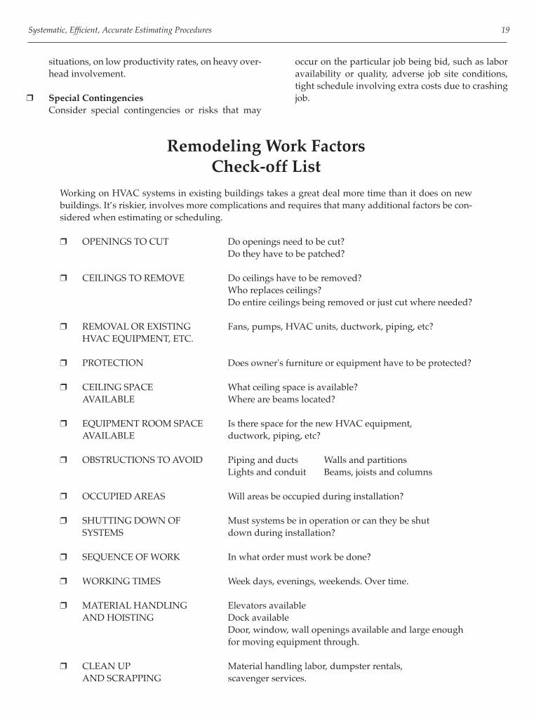
Remodeling Work FactorsCheck-off List
Working on HVAC systems in existing buildings takes a great deal more time than it does on new buildings. It’s riskier, involves more complications and requires that many additional factors be con-sidered when estimating or scheduling.
❒ OPENINGS TO CUT Do openings need to be cut? Do they have to be patched?
❒ CEILINGS TO REMOVE Do ceilings have to be removed? Who replaces ceilings? Do entire ceilings being removed or just cut where needed?
❒ REMOVAL OR EXISTING Fans, pumps, HVAC units, ductwork, piping, etc? HVAC EQUIPMENT, ETC.
❒ PROTECTION Does owner's furniture or equipment have to be protected?
❒ CEILING SPACE What ceiling space is available? AVAILABLE Where are beams located?
❒ EQUIPMENT ROOM SPACE Is there space for the new HVAC equipment, AVAILABLE ductwork, piping, etc?
❒ OBSTRUCTIONS TO AVOID Piping and ducts Walls and partitions Lights and conduit Beams, joists and columns ❒ OCCUPIED AREAS Will areas be occupied during installation?
❒ SHUTTING DOWN OF Must systems be in operation or can they be shut SYSTEMS down during installation?
❒ SEQUENCE OF WORK In what order must work be done?
❒ WORKING TIMES Week days, evenings, weekends. Over time.
❒ MATERIAL HANDLING Elevators available AND HOISTING Dock available Door, window, wall openings available and large enough for moving equipment through.
❒ CLEAN UP Material handling labor, dumpster rentals, AND SCRAPPING scavenger services.
occur on the particular job being bid, such as labor availability or quality, adverse job site conditions, tight schedule involving extra costs due to crashing job.

20 Mechanical Estimating Manual
15 Bastards with No Regular HomesCheck-off List
Responsibility for furnishing these 15 bastard items keep switching from one part of the specs or contract doc-uments to another and back again, and can drive sheet metal and piping contractors and others right up the wall. These are items that may be part of your contract on one job and not on the next.
• Responsibility for furnishing an item can be found in any of six different parts of the specifi cations on six different projects.
• The items required in your specifi cations may show up on any of the fi ve different sets of drawings: ar-chitectural, lab equipment, piping, kitchen equip-ment, or ventilation.
• Contract documents may not say explicitly “fur-nish” or “don’t furnish.”
The 15 bastards that evade regular assignment in sheet metal and piping bids are as shown in the following check-off list:
❒ Starters, Final wiring❒ Louvers❒ Coils in air handling units❒ Electric duct coils❒ Rooftop units❒ Air system testing and balancing❒ Breechings, stacks and fl ues❒ Insulation❒ Finish painting❒ Concrete pads❒ Roof curbs, Duct chases❒ Wall and ceiling access doors❒ Exhaust hoods
The Problems That ResultThe Industry’s approach of randomly assigning respon-sibility for furnishing and installing these components creates complications and confusion for bidders; it leads to omissions, duplications, overlapping, and errors; it cre-ates contingency allocations in bids. Haphazard assignment of responsibility and lo-cation on drawings wastes time, money and energy. It
causes delays, battles, district, lawsuits, exasperating wrangles, dissatisfi ed customers, and even bankruptcy.
With unclear, indefi nite plans and specs, the owner may pay twice for items, because two contractors want to cover themselves in this risk situation and both put money in their bids for the item.
Or no contractor includes money in his bid for an item-let’s say access doors in walls and ceilings and when the moment comes for these to be installed near the end of the job and the owner ends up pay-ing more for the item than he would have at bid time as an extra.
Or one contractor furnishes the item-free because he is forced to, based on “It’s implicit in the contract documents,” etc.
A contractor can lose $5,000 here on starters, $4,000 there on fi nish painting and $3,000 somewhere else on fi -nal wiring without blinking. An owner may pay $5,000 twice for the same lou-vers or $2,000 to two different contractors for installing the same electric heating coils.
Contributing Factors Obviously, the number one reason why these items have no regular homes is that the construction industry is neither uniform nor consistent in assigning responsibility for furnishing and installing specifi c items. The second culprit is vagueness or hedging, not be-ing defi nite or clear as to who should furnish an item, who should install it, and who should pay for installation labor. General contractors cause some of this chaos when they are the primes, chopping up the specs differently from how they were written. A general may take insula-tion out of the heating and ventilating sections and sub it himself He may want to furnish the louvers himself even though they are in the ventilation specs. Confusion, ignorance, and indifference regarding union jurisdiction over who does what and contractor as-sociation agreements on who furnishes what contribute to the diffi culty in properly grouping and assigning all items involved. Often a lack of knowledge by the preparer of the contract documents as to how things are installed most economically, what the various contractors actually do, hampers uniformity and consistency in spec writing and drawing. Time pressures, convenience, self interest, the chang-

Systematic, Effi cient, Accurate Estimating Procedures 21
ing industry, new or untrained personnel, and costs may infl uence A-Es in their preparation of construction docu-ments.
All man hour fi gures in this manual for everything, ductwork, accessories, equipment, etc. include all direct and indirect labor operations as follows:
AD Shop Labor for Sheet Metal Includes:
1. Unloading and storing raw materials 2. Listing, shop tickets, shear sizes 3. Getting materials from stock 4. Blanking 5. Layout and cutting 6. Forming 7. Seaming 8. Assembling 9. Cleats 10. Hangers 11. Reinforcing angles 12. Loading assembled items on truck 13. Idle and non-production time 14. Supervision time
All Field Labor Includes: 1. Unloading and distribution 2. Unpacking 3. Set up scaffolding, tools, ladder 4. Layout of hangers, etc. 5. Actual hanging of ductwork and piping, or setting
up of equipment 6. Tear down of scaffolding, etc. and clean up 7. Idle and non-production time 8. Supervision time
The Following Items are Not Included in theRegular Labor Tables Field Sketching Shop Drawings Truck Driver Labor
Operations Included in Labor Hours
Lack of coordination among the architect, structural engineer, mechanical engineer, electrical engineer, and spec writers adds to the dilemma.

This page intentionally left blank

23
OVERVIEW OF SAMPLE JOB
Sample HVAC Estimate The following sample estimate is of a small 6,800 sq ft offi ce building with a low pressure, single zone galvanized duct system, an air handling unit and a split DX system. It includes most of the typical air distribution components in it involved in most projects such as rectangular and round galvanized ductwork, the air handling unit, the roof exhaust fan, dampers, louvers, grilles, registers and diffusers, duct wrap, acoustic liner, duct accessories, etc. Treat as if you are the prime HVAC contractor, do-ing the air distribution portion while subbing out the re-frigeration and heating pans.
PURPOSE OF FORMS
Forms are an indispensable aid and guide to orga-nized, effi cient and thorough estimating. They help con-trol the proper sequence of estimating work, continually remind you of what information is needed, lead you logi-cally through calculations and as a result your bids will be more complete and correct.
Job Description and Budget Costs Form1. Budget estimate prices to determine if it should be
bid or not, and as a check price against the detailed estimate after the bid is complete.
2. Approximate heating, cooling and CFM loads and rough out ductwork weight for check on detailed ductwork takeoff.
3. Record the key characteristics of the type of system involved.
Per Piece Duct Takeoff Sheet Estimating ductwork labor by the piece is the most accurate and clearest method available for contractors. The takeoff involves listing the duct size, type, quantities on fi ttings and lengths on straight duct.
The extension of material involves totaling footages per line, entering the weight per running foot and multi-plying for the total material weight on each line. The ex-tension of labor involves totaling the quantity of pieces, looking up and entering labor hours per piece for the shop and fi eld and multiplying out for the totals per fi ne. After the fi nes are extended the columns are totaled.
Quantity Takeoff Sheet and Extension Sheet The quantity takeoff sheet is a general form for tak-ing off and listing types, sizes, quantities, etc. of the vari-ous items required in a bid other than ductwork or pip-ing, for extending the material amounts, labor, costs, etc. and summations.
Estimate Summary and Extension Sheet The summary sheet is used as a fi ne item summary of all the major grouping of different items included in the estimate, from ductwork and other takeoff sheets, etc. It should be divided into the major divisions of a bid, quoted equipment, ductwork, piping, specialties and ac-cessories, miscellaneous labor, etc. The total amounts of material quantities, labor, etc. are transferred from duct and piping takeoff sheets, quan-tity takeoff sheets etc. to this summary sheet.
Bid Recap Sheet1. Recap the job totals of direct costs on labor and pric-
es on raw materials, equipment and sub contractors, and to total them.
2. Put markups on each group and total the overhead markup.
3. Put a profi t markup on the labor, raw material, equipment and sub-contractor groups.
4. Total everything for a bottom line bidding price.
Calculating Labor Costs Per Hour This form insures that all the components of the wage rate which include, base wage rate, normal union
Chapter 3
Sample HVAC Estimate and Forms

24 Mechanical Estimating Manual
fringe benefi ts, federal and state payroll taxes, insurance’s and dues, are covered in the rate used in a bid.
Telephone Quotations Form The telephone quotation form is for recording quo-tations which come over the phone, in an organized, com-plete and readable fashion. It includes a check-off list on the bottom of critical aspects of a quote such as, if they meet plans and specifi cation requirements, addendum’s,
taxes, freight, lead times, etc. A box is provided for excep-tions on what is not included.
Bidding Record Form The purpose of the bidding record form is to have a written record of who the phone bid were given to, what the amount was, what the inclusions and exclusions were and what the plans, specifi cations and addenda of the bids were based on.
IBM Sales Offi ceA. Related Documents The general provisions of the contract, the general
conditions and supplementary conditions of these specifi cations plus the A/A document A201-1976 “general conditions” apply to the work in this speci-fi cation.
B. Scope of Work Scope of work to include, but not be limited to the following:
Equipment 1. Air handling unit 2. Roof exhaust fans 3. Grilles and registers 4. Ceiling diffusers, lay in 5. Fire dampers with sleeves 6. Control dampers 7. Louvers
Ductwork 8. Galvanized ductwork, low pressure 9. Spiral 10. Flexible tubing 11. Flues
Specifi cations on Sample Job
Sheet Metal Specialties 12. Turning Vanes 13. Splitter and manual volume dampers 14. Access Doors 15. Flexible Connections Insulation 16. Liner, RA duct, 1,” 2 lb density 17. Duct wrap, OA Duct, 1- 1/2,” 3/4 lb density
Miscellaneous 18. Prepare blown up shop drawings 19. Test & balance air distribution system 20. Refrigeration piping, valves, condenser, insula-
tion 21. Temperature Controls 22. Insulation C. Work Not Included 1. Painting 2. Power wiring to mechanical equip. 3. Structural steel openings 4. Condensate piping 5. Gas Piping 6. Concrete Pads 7. Starter

Sample HVAC Estimate and Forms 25
IBM Offi ces, Drawing M-1Low Pressure, Galvanized, Cleat Connections, SZ
Split DX System

26 Mechanical Estimating Manual
Job Description and Budget Costs

Sample HVAC Estimate and Forms 27
Per Piece Duct Takeoff SheetGalvanized

28 Mechanical Estimating Manual
Quantity Takeoff Sheet

Sample HVAC Estimate and Forms 29
Estimate Summary and Extension Sheet

30 Mechanical Estimating Manual
Bid Recap and Markup Sheet

Sample HVAC Estimate and Forms 31
Calculating Labor Costs Per Hour

32 Mechanical Estimating Manual
Telephone Quotation

Sample HVAC Estimate and Forms 33
Bidding Record

This page intentionally left blank

Section II
Budget Estimating

This page intentionally left blank

37
There Are Three Basic Types of Estimates 1. Conceptual or budget estimating 2. Semi-detailed budget estimating 3. Detailed estimating
BUDGET ESTIMATES
A conceptual budget estimate is a quick, approximate price without extensive quantity surveys or pricing calculations of the specifi c of items that comprise a bid. Contractors use conceptual budget estimates in the following ways:• To help determine if they should bid a job or not.• To know approximately what the total price of a project
should be before preparing a detailed estimate.• Quick pricing for customer, general contractor or A/
E.• As a check of your estimate after you’re done.• For budgeting purposes, comparing design costs,
feasibility studies.• As a check on current market pricing.• For negotiating.• To check incoming bids and quotations.
There are two basic types of budget estimates, one for budgeting the overall price of the project or trade, and the other, the semi-detailed one, for budgeting individual component parts and totaling for the job. The conceptual estimate issued for overall pricing, is a rough approximation based on some unit of measurement of the building or system:
— 10,000 sq ft Offi ce Building @ $7.00/sq ft for HVAC = $70,000
— 100 Tons of Air Cond. in a Store @ $1500.00/Ton = $150,000
— 100,000 sq ft High School @ $9.00/sq ft for sheet metal = $900,000
Conceptual pricing should normally not be used for bidding with any fi rm commitment on the price. Your price may be reasonably accurate, even right on, but it also can be off the mark 20 to 25% one way or the other due to variations in design, scope, etc. You may look at an offi ce building, fi gure $7.00/sq ft, fi nd out later, upon closer inspection or doing the job, that this particular offi ce building runs $8.00/sq ft and you lose $20,000 on a 20,000 sq ft job.
SEMI-DETAILED SCOPE BUDGET ESTIMATES
Semi-detailed budget estimates, the second basic approach to pricing construction work is far more accurate than a conceptual one. It is “on” more frequently and only has a potential inaccuracy of 10 to 15% while still being a very speedy way to price without the tedious, length takeoffs and extensions. In semi-detailed estimating you break the job down into component parts, as you would a fully detailed one, listing all the individual items on a summary and extension sheet. But instead of a long exact take off on each and extensive pricing, the quantities and the prices of the various components are budgeted; i.e., they are approximated in some expedient manner. A thorough preliminary survey is made, again, as you would on a fully detailed bid, to insure covering and knowing the entire scope of the project and so that spec requirements are met.
Ductwork Budgeting Ductwork weight is approximated by using an average weight per square foot of building, or by measuring the total linear footage with a measuring wheel, and multiplying it times the approximate average weight per linear foot. Ductwork costs for the project are then found by multiplying the budget price per pound or per foot, based on inspection and judgment, times the approximate weight or linear footage.
Piping Budgeting• Main Piping Runs Per Foot• Piping Assembly Hookups To Equipment Per
Assembly Price
Equipment Pricing Equipment costs are determined in one of two ways. If the equipment has been sized and specifi ed suppliers can furnish approximate pricing. The second pricing is budgeting by the cost per CFK square foot, linear foot, etc. or by the size. Equipment labor is determined either by the average size or the specifi c sizes. Again, as with conceptual budget estimates, it is very risky business bidding fi rm quotes based on semi-detailed estimates. However, you can chance it, when the situation demands it by adding 10 or 15% on top to cover the possible range of error.
Chapter 4
Budget Estimating

38 Mechanical Estimating Manual
DETAILED ESTIMATES
The only truly reliable estimate is the fully detailed one which absolutely minimizes the risks of being far too low or high, where the odds are greatly in your favor that the estimate is a true representation of the job.
Budget Estimating HVAC Costs and Engineering LoadsPer Square Foot of Building and Per Ton
————————————————————————————————————————————————— HEATING DUCT TOTAL HVAC COOLING LOAD LOAD SUPPLY WEIGHT SELLING PRICE TYPE BUILDING ——————— ——— ——— ——— ——————— Btu Per Sq Ft Btu Per CFM Per lbs Per Per Per Sq Ft Per Ton Sq Ft Sq Ft Sq Ft Sq Ft Ton—————————————————————————————————————————————————Apartments, condominiums 25 480 26 0.8 0.2 $5.22 $2,491Auditoriums 40 300 40 1.3 0.8 13.56 4,066Banks 48 250 26 1.6 1.2 14.71 3,672Bowling Alleys 40 300 40 1.3 0.6 10.66 3,197Churches 36 330 36 1.2 0.5 11.65 3,848Clubhouses 50 240 40 1.6 1.0 10.39 2,491Cocktail Lounges 70 170 30 1.3 1.2 14.71 2,497Computer Rooms 140 85 20 4.5 1.5 30.67 2,602—————————————————————————————————————————————————Colleges: Admin., Classrooms 44 270 42 1.5 1.3 21.50 5,810 Dormitories -- -- 25 -- 0.3 12.28 -- Gyms, Fieldhouses -- -- 40 0.5 0.3 9.12 -- Science Bldgs. 54 220 55 1.8 1.4 16.47 3,622—————————————————————————————————————————————————Court Houses 50 240 36 1.6 1.2 14.83 3,555Fire Stations -- -- 35 -- 0.7 9.12 --Funeral Homes 30 400 32 0.9 0.8 10.36 3,522Hospitals 44 170 28 1.4 1.5 28.76 4,885Hotels 34 350 28 1.1 0.5 7.99 3,432Housing for Elderly -- -- 28 -- 0.2 7.84 --Jails 25 480 30 0.8 1.2 13.93 5,810Laboratories 60 200 50 2.0 1.5 27.72 5,546Libraries 46 260 37 1.5 1.3 15.95- 4,148—————————————————————————————————————————————————Manufacturing Plants 40 300 36 1.3 0.4 5.85 1,748Medical Centers, Clinics 35 340 35 1.1 1.0 10.36 3,522Motels 30 400 30 1.0 0.s 6.72 2,683Municipal Bldgs., Town Halls 45 265 36 1.4 1.2 15.21 4,027Museums 34 350 40 1.1 0.8 11.41 3,990Nursing Homes 43 280 34 1.4 0.5 13.69 3,827—————————————————————————————————————————————————Offi ce Bldgs: Low Rise 35 340 35 1.1 .5 to .8 10.36 3,522 High Rise 40 300 30 1.3 1.1 14.83 4,446 Small Plant Off. 34 350 35 1.1 0.5 7.40 2,590—————————————————————————————————————————————————Police Stations 42 285 35 1.3 1.0 9.99 2,850Post offi ces 44 270 40 1.4 1.2 15.21 4,103Project Homes -- -- 28 -- 0.1 3.64 --Restaurants 80 150 35 2.0 1.0 16.34 2,224Residences 25 500 30* 0.8 0.3 4.84 2,406—————————————————————————————————————————————————Schools: Elementary -- -- 26 0.8 0.7 11.41 -- Middle, Jr. Highs 36 333 26 1.0 1.1 14.56 4,409 High schools 33 360 40 1.1 1.3 13.44 4,831 Vocational 20 600 40 0.9 1.5 30-90 --—————————————————————————————————————————————————Stores: Beauty Shops 63 190 30 2.0 1.3 16.47 3,127 Department 34 350 30 1.1 0.7 9.26 3,235 Discount 30 400 32 1.1 0.4 6.36 2,217 Retail Shops 50 340 32 1.6 0.8 10.64 3,616 Shopping Centers 30 400 30 1.1 0.4 5.22 2,076 Supermarkets 30 400 32 1.0 0.4 5.45 2,179—————————————————————————————————————————————————Theaters 40 300 40 1.3 0.8 10.51 3,152Warehouses -- -- 20 -- 0.2 3.82 --—————————————————————————————————————————————————1. Cooling load based on is temp. differences, 50% RH, 400 CFM per ton.2. Heating load based on 70 temp. differences and is the output Btu. Apply ineffi ciency factor to heating equipment for input Btu.3. Price includes all HVAC material, labor and subs and overhead and profi t. *R-11 wall and R-19 ceiling insulation
In a detailed estimate the systems and work are broken down into the smallest type components and sizes in which they can be priced with reasonable accuracy and practicality. All items, are components, are taken off and priced separately by specifi c sizes, types, accessories, etc.

Budget Estimating 39
Budget Estimating Galvanized DuctworkPer Pound and Per Foot
Standard Low Pressure HVAC Rectangular Galvanized25 Percent Fittings, New Construction, 10 Foot High, 1st Floor
———————————————————————————————————————————
SEMI- SELLING PRICE * PERIM LB/FT SQ FT/FT Furnished & Installed SIZE ——— GAUGE w/20% No Waste Inches Waste Per Lb. Per Ft. ——— ——— ———— ——— ——— ——— ——— 6x6 12 26 Ga. 2.8 2.0 $5.14 $14.39 12x6 18 3.3 3.0 4.96 16.34 12x12 24 4.4 4.0 4.77 22.07——————————————————————————————————————————
18x6 24 24 Ga. 5.6 4.5 4.77 26.71 18x12 30 7.0 5.0 4.62 33.24 24x9 33 7.7 6.5 4.54 34.94 24x12 36 8.4 6.0 4.47 37.49 24x15 39 9.2 6.5 4.47 41.07 30x12 42 9.8 7.0 4.38 42.99 30x18 48 11.2 8.0 4.31 48.26 30x24 54 12.6 9.0 4.23 53.34——————————————————————————————————————————
36x12 48 22 Ga. 13.6 8.0 4.23 57.57 36x18 54 15.3 9.0 4.13 63.11 36x24 60 17.0 10.0 4.00 68.04 42x12 54 15.3 9.0 4.13 63.11 42x18 60 17.0 10.0 4.00 68.04 42x24 66 18.7 11.0 3.97 74.27 48x12 60 17.0 10.0 4.00 68.04 48x18 66 18.7 11.0 3.97 74.27 48x24 72 10.4 12.0 3.94 80.41 54x24 78 22.1 13.0 3.91 86.40 54x30 84 23.8 14.0 3.88 92.32 54x36 90 25.5 15.0 3.85 98.12——————————————————————————————————————————
60x15 78 20 Ga. 26.0 13.0 3.88 100.85 60x24 84 28.0 14.0 8.50 108.60 60x30 90 30.0 15.0 3.85 115.44 72x24 96 32.0 16.0 3.82 122.14 72x30 102 34.0 17.0 3.79 128.75 72x36 108 35.3 18.0 3.74 132.03 84x30 114 38.0 19.0 3.82 140.38 84x36 120 40.0 20.0 3.67 146.53 84x42 126 42.0 21.0 3.63 152.56——————————————————————————————————————————
96x24 120 18 Ga. 52.6 21.0 3.60 189.44 96x36 132 57.2 22.0 3.57 204.25 96x48 144 62.4 24.0 3.54 220.90 96x72 168 72.8 28.0 3.51 255.51 96x96 192 83.2 32.0 3.48 289.37——————————————————————————————————————————
*Selling price based on $.42 per pound for galvanized, $39.00 per hour for labor, a 30 percent markup on direct costs for overhead and a 5 percent markup for profi t. The price includes material and all labor for the fabrication, installation, drafting and shipping.
CORRECTION FACTORS ON SELLING PRICE OF GALVANIZED DUCTWORK1. Percent fi ttings by weight, 15% .................0.09 25%.................1.00 35% .................1.08 45%.................1.152. Different wage rates (incl. base pay, fringes, payroll taxes, ins.) $12.00 (per hour) ......... 0.66 $22.00.................0.89 15.00 ............................ 0.77 26.50.................1.00 18.00 .............................0.80 30.00.................1.08
3. Overall residential factor for 15 percent fi ttings, $12.00 per hour gross wages and lighter gauges ... 0.50 times cost per lb or per foot. Example: 24” x 8 $4.15/lb equals $2.08/lb $31.90/ft equals $15.95/ft

40 Mechanical Estimating Manual
Installed Price Per Square Foot forDifferent Types of DuctworkAverage Size 24”x12” in a Typical Mix
25 Percent Fittings by Square Feet
Installed price per square foot includes material, shop labor, fi eld labor, shop drawings, shipping and a 35 percent markup on costs for overhead and profi t. Labor is based on $39.00 per hour.

Budget Estimating 41
Per Square Foot Ductwork Cost ComparisonAverage Size 24”x12”
25 Percent Fittings By Square Feet
DIRECT SHOP FIELD BUDGET TYPE MATERIAL LABOR LABOR PRICE DUCT DESCRIPTION COST* ——————— ——————— with per ft hr per per ft hr per 30% O&P per sq ft per hr sq ft per hr sq ft per sq ft————————————————————————————————————————————————STAINLESS 24 gauge with cleats $3.18 30 0.03 17 0.06 $8.81
STEEL ————————————————————————————————————————— 18 gauge welded seams
metal fl anged and bolted 6.50 10 0.10 15 0.07 16.90
—————————————————————————————————————————ALUMINUM 20 gauge .032” thick
cleat connections 0.87 33 0.03 19 0.05 5.34
—————————————————————————————————————————FRP 3/16” thick coupling
or fl ange connection 4.40 12 0.08 is 0.07
1-3.32
—————————————————————————————————————————PVC 1/8” or 3/16” thick
fl ange or slip connections 5.12 23 0.04 16 0.06 12.03
—————————————————————————————————————————PVC (PVS)
COATED 22 gauge with cleats or
GALVANIZED fl anged and bolted 2.80 30 0.03 17 0.06 8.31
—————————————————————————————————————————BLACK IRON metal fl anges, bolted,
10 gauge 3.27 9 0.11 10 0.10 14.96
————————————————————————————————————————— 14 gauge 1.82 11 0.09 14 0.07 10.60
————————————————————————————————————————— angle fl anges, bolted
10 gauge 6.67 8 0.13 9 0.11 20.65
————————————————————————————————————————— 14 gauge 2.29 10 0.10 13 0.08 11.95
————————————————————————————————————————— 16 gauge, kitchen exhaust
welded connections, NFPA 96 1.42 16 0.06 10 0.10 10.09
—————————————————————————————————————————FIBER 800 board, stapled and
GLASS taped, rod reinforcing 1.49 55 0.02 30 0.03 4.56
—————————————————————————————————————————GALVANIZED low pressure, unlined 0.74 38 0.03 22 0.05 4.60
————————————————————————————————————————— low pressure, 1” lining, 1-1/2 lb. 1.47 22 0.05 21 0.05 6.62
—————————————————————————————————————————SPIRAL pipe and fi ttings, medium
pressure, slip connections sealed 0.75 47 0.02 24 0.04 4.17————————————————————————————————————————————————Sell budget prices include material, shop and fi eld labor, shop drawings, fi eld measuring, shipping, and a 30% markup for overhead
and profi t.
*Material costs includes sheet metal, connection materials, hangers, scrap hardware.
Labor rate $39.00 per hour.

42 Mechanical Estimating Manual
Budget Estimating Insulation and Lining Per FootStandard HVAC Rectangular Ductwork25 Percent Fittings by Square Footage
———————————————————————————————————————— SEMI- SELLING PRICE PERIM SQ FT/FT Furnished & Installed SIZE ——— with 15% per Ft (w & d) Waste Inches Insulation Lining
———————————————————————————————————————— 6x6 12 2.3 $5.06 $4.32
12x6 18 3.5 7.70 5.64
12x12 24 4.6 10.12 8.63————————————————————————————————————————
18X9 24 5.2 11.46 9.75
18x12 30 5.8 12.76 10.79
24x9 33 7.5 16.52 14.09
24x12 36 6.9 15.21 12.95
24x15 39 7.5 16.52 14.09
30x12 42 8.0 17.61 15.02
30x18 48 9.2 20.26 17.27
30x24 54 10.4 22.88 19.52————————————————————————————————————————
36x12 48 9.2 20.26 17.27
36x18 54 10.4 22.88 19.52
36x24 60 11.5 25.32 21.59
42x12 54 10.4 22.88 19.52
42x18 60 11.5 25.32 21.59
42x24 66 12.7 27.96 23.84
48x12 60 11.5 25.32 21.59
48x18 66 12.7 27.96 22.54
48x24 72 13.8 30.37 25.91
54x24 78 15.0 33.02 28.16
54x30 84 16.1 35.43 30.24
54x36 90 17.3 38.08* 32.486————————————————————————————————————————
60x18 78 15.0 33.02 28.16
60x24 84 16.1 35.43 30.24
60x30 90 17.3 42.70 32.49
72x24 96 18.4 40.49 33.80
72x30 102 19.6 43.14 36.81
72x36 108 20.7 45.55 38.86
84x30 114 21.9 48.20 39.43
84x36 120 23.0 50.63 43.19
84x42 126 24.1 53.04 45.26————————————————————————————————————————
96x24 120 24.2 53.27 45.44
96x36 132 25.3 55.69 68.01
96x48 144 27.6 60.75 51.83
96x72 168 32.2 70.88 60.46
96x96 192 36.8 80.99 69.12————————————————————————————————————————
1. Lining is based on 1 inch thick 1-1/2 pound density fi ber glass blanket at $1.48 per sq. ft. installed. Installed selling prices based on $39.00 per hour for labor, a 25 percent markup for overhead and a 5 percent markup for profi t. Includes all pins, tapes, cement, materials and labor.
2. Galvanized ductwork weight must be increased 12 percent to compensate for increasing the metal duct size one inch for the lining.

Budget Estimating 43
Budget Estimating External Insulation Per FootStandard HVAC Rectangular Ductwork25 Percent Fittings By Square Footage
SEMI- SELLING PRICE PERIM SQ FT/FT Furnished SIZE -------- With 15% & Installed (w & d) Waste per ft Inches Insulation
—————————————————————————————— 6x6 12 2.3 $5.06
12x6 18 3.5 7.70
12x12 24 4.6 10.12——————————————————————————————
18x9 24 5.2 11.46
18x12 30 5.8 12.76
24x9 33 7.5 16.52
24x12 36 6.9 15.21
24x15 39 7.5 16.52
30x12 42 8.0 17.61
30x18 48 9.2 20.26
30x24 54 10.4 22.88——————————————————————————————
36x12 48 9.2 20.26
36x18 54 10.4 22.88
36x24 60 11.5 25.32
42x12 54 10.4 22.88
42x18 60 11.5 25.32
42x24 66 12.7 27.96
48x12 60 11.5 25.32
48x18 66 12.7 27.96
48x24 72 13.8 30.37
54x24 78 15.0 33.02
54x30 84 16.1 35.43
54x36 90 17.3 38.08——————————————————————————————
60x18 78 15.0 33.02
60x24 84 16.1 35.43
60x30 90 17.3 42.70
72x24 96 18.4 40.49
72x30 102 19.6 43.14
72x36 108 20.7 45.55
84x30 114 21.9 48.20
84x36 120 23.0 50.63
84x42 126 24.1 53.04——————————————————————————————
96x24 120 24.2 53.27
96x36 132 25.3 55.69
96x48 144 27.6 60.75
96x72 168 32.2 70.88
96x96 192 36.8 80.99——————————————————————————————
1. External insulation based on 1-1/2 inch thick 3/4 pound density fi ber glass with vapor barrier, at $1.72 per sq. ft. installed.

44 Mechanical Estimating Manual
Budget Estimating InsulationExternal Wrapping For Ductwork Per Square Foot
————————————————————————————————————————————————— MATERIAL SELLING DENSITY LABOR COST PRICE* ITEM THICKNESS ————— ————— w/O&P Lbs Per Sq Ft Per Per Inches Cu Ft Per Hour Sq Ft Sq Ft————————————— —————— ————— —————— ————— ————FIBER GLASS BLANKET, RFK Vapor Barrier or Vinyl 1 3/4 50 $0.46 $1.91 1-1/2 3/4 45 0.62 2.34 2 3/4 40 0.81 2.85—————————————————————————————————————————————————FIBER GLASS, RIGID BOARD With RFK Vapor Barrier 1 3 16 0.53 4.21 With 8 oz. Canvas Cover 1 3 15 0.71 4.77 With 8 oz. Canvas and Painted 1 3 14 0.80 5.18
With RFK Vapor Barrier 2 3 13 0.62 5.11 With 8 oz. Canvas Cover 2 3 12 0.54 5.28 With 8 oz. Canvas and Painted 2 3 11 0.60 5.78—————————————————————————————————————————————————OUTSIDE.FIBER GLASS, RIGID BOARD With 2 Layers black mastic, glass mesh 1 4 -- ----- 5.09 2 4 -- ----- 5.67—————————————————————————————————————————————————KITCHEN EXHAUSTS & BREECHING Calcium Salicate Block (K Block) Rectangular 2 -- 8 2.03 10.29 Round 2 -- 7 2.72 12.55 With 1/2” Cement Rectangular 2 -- 5 3.61 17.18 Round 2 -- 4 4.75 21.94 Fiber Glass, Rigid Board with covering and paint 2 4 8 1.33 8.93—————————————————————————————————————————————————*Includes 15% waste, pins, staples, tape, installation, supervision, 20% overhead and 5% profi t. Based on union wages of $39.00per hour, 10 foot high ducts, lower fl oors, normal space conditions.
CORRECTION FACTORS 1. Congested ceiling spaces, areas 1.15 2. Wage rate at $39.00 per hour

Budget Estimating 45
Budget Estimating Copper TubingInstalled Price Per Foot
95/5 Solder, 300F
Includes 2 Fittings Per 20 Feet of Pipe, Hangers and SolderStandard Installation Conditions, Lower Floors, 10 Ft High
——————————————————————————————————————————— DIA. Inches L M K DWV —————— —————— —————— —————— —————— 1/2 $9.32 $8.39 $10.03 $8.81 3/4 11.83 10.64 13.23 11.17 1 15.OB 13.26 16.71 13.93 1-1/4 18.97 17.08 23.41 17.95 1-1/2 21.70 19.54 23.77 20.51 2 28.00 25.19 30.71 26.46 —————— —————— —————— —————— —————— 2-1/2 38.36 33.68 41.00 35.36 3 45.57 41.03 49.91 43.07 4 65.11 58.59 75.95 61.52 5 117.20 105.48 138.63 110.75 6 154.08 138.68 200.01 145.62 8 282.13 228.53 335.86 239.20
———————————————————————————————————————————Prices include all material costs, labor at $51.00 per hour and overhead and profi t markup.
Budget Estimating Steel PipingInstalled Price Per Foot
Includes 2 Fittings Per 20 Feet of Pipe, HangersStandard Installation Conditions, Lower Floors, 10 Ft High
——————————————————————————————————————————— DIA. SCREWED WELDED FLANGED GROOVED Inches Sch. 40 Sch. 40 Sch. 40 Sch. 40 —————— —————— —————— —————— —————— 1/2 $8.54 ---- ---- ---- 3/4 9.00 ---- ---- 7.70 1 10.74 13.96 ---- 8.47 1-1/4 12.24 15.30 ---- 9.24 1-1/2 13.85 16.49 ---- 11.54 2 17.85 18.65 33.94 15.24 —————— —————— —————— —————— —————— 2-1/2 23.68 24.61 40.17 19.24 3 28.98 29.91 46.18 23.09 4 37.99 39.72 62.34 30.55 5 60.03 55.23 78.50 40.17 6 73.88 66.94 96.20 53.56 8 99.28 83.40 125.44 80.97 10 115.44 95.82 187.01 108.85 —————— —————— —————— —————— —————— 12 168.54 129.93 253.97 135.76 14 ---- ---- 295.53 ---- 16 ---- ---- 341.70 ---- 18 ---- ---- 369.41 ---- 20 ---- ---- 420.20 ---- 22 ---- ---- 434.05 ---- 24 ---- ---- 458.68 ----
———————————————————————————————————————————Prices include all material costs, labor at $51.00 per hour and overhead and profi t markup.

46 Mechanical Estimating Manual
Budget Estimating PVC Pressure PipingInstalled Price Per Foot
Includes 2 Fittings Per 20 Feet of Pipe, Hangers and SolventStandard Installation Conditions, Lower Floors, 10 Ft High
————————————————————————————— LABOR TOTAL MATERIAL & LABOR DIA ———— ———————————— Man Direct With Hours Cost 20% O&P
————————————————————————————— 1/2” 0.140 $6.81 $8.17 3/4” 0.148 $7.18 $9.33 1” 0.129 $6.14 $7.98 1-1/4” 0.147 $7.02 $9.13
————————————————————————————— 1-1/2” 0.149 $7.23 $9.40 2” 0.156 $7.75 $10.07 2-1/2” 0.177 $9.83 $12.78 3” 0.229 $12.90 $16.76 4” 0.317 $13.36 $17.37
—————————————————————————————Direct labor costs are $39.00 per hour.
Budget Estimating Cast Iron Piping, Hub and Spigot Installed Price Per Foot
Includes 2 Fittings Per 20 Feet of Pipe, HangersStandard Installation Conditions, Lower Floors, 10 Ft High
————————————————————————————— LABOR TOTAL MATERIAL & LABOR DIA ———— ———————————— Man Direct With Hours Cost 20% O&P
————————————————————————————— 2” 0.212 $12.64 $15.16 3” 0.305 $18.41 $23.93 4” 0.331 $20.33 $26.43 5” 0.378 $25.27 $32.85
————————————————————————————— 6” 0.432 $29.43 $38.26 8” 0.574 $45.97 $59.76 10” 0.761 $67.39 $87.61 12” 0.835 $87.83 $114.18 15” 1.112 $146.28 $190.16
—————————————————————————————Direct labor costs are $39.00 per hour.

Budget Estimating 47
Threaded Bronze and Iron Valves————————————————————————————————————— TOTAL TYPE DIRECT LABOR MATERIAL & LABOR SIZE ———— MATERIAL ———— —————————— COST Man Direct With Material Hours Cost 30% O&P ———— ———— ————— ———— —————————— GATE 1/2 Bronze $22.79 0.65 $48.14 $62.58 3/4 Bronze 29.53 0.72 57.61 74.89 1 Bronze 35.74 0.78 66.16 86.01 1-1/4 Bronze 47.95 0.91 83.44 108.47 1-1/2 Bronze 61.02 0.98 99.24 129.01————————————————————————————————————— 2 Bronze 85.00 1.04 125.56 163.22 2-1/2 Iron 283.32 1.80 353.52 459.57 3 Iron 348.69 1.90 422.79 549.62 4 Iron 435.86 2.00 513.86 668.02————————————————————————————————————— 5 Iron 0.00 0.00 0.00 0.00 6 Iron 0.00 0.00 0.00 0.00 8 Iron 0.00 0.00 0.00 0.00 CHECK————————————————————————————————————— 1/2 Bronze $24.42 0.65 $49.77 $64.70 3/4 Bronze 27.65 0.72 55.73 72.44 1 Bronze 36.19 0.78 66.61 86.59 1-1/4 Bronze 51.06 0.91 86.55 112.52 1-1/2 Bronze 57.72 0.98 95.94 124.72————————————————————————————————————— 2 Bronze 88.80 1.04 129.36 168.17 2-1/2 Iron 213.12 1.80 283.32 368.32 3 Iron 255.30 1.90 329.40 428.22 4 Iron 388.50 2.00 466.50 606.45————————————————————————————————————— 5 Iron 0.00 0 0.00 0.00 6 Iron 0.00 0 0.00 0.00 8 Iron 0.00 0 0.00 0.00 BALL————————————————————————————————————— 1/2 Bronze $7.87 0.65 $33.22 $43.19 3/4 Bronze 12.55 0.72 40.63 52.82 1 Bronze 16.10 0.78 46.52 60.48 1-1/4 Bronze 28.09 0.91 63.58 82.65 1-1/2 Bronze 35.74 0.98 73.96 96.15————————————————————————————————————— 2 Bronze 44.40 1.04 84.96 110.45 2-1/2 Iron 0.00 0.00 0.00 0.00 3 Iron 0.00 0.00 0.00 0.00 4 Iron 0.00 0.00 0.00 0.00————————————————————————————————————— 5 Iron 0.00 0 0.00 0.00 6 Iron 0.00 0 0.00 0.00 8 Iron 0.00 0 0.00 0.00—————————————————————————————————————Direct labor costs are $39.00 per hour.

48 Mechanical Estimating Manual
Threaded Bronze and Iron Valves————————————————————————————————————— TOTAL TYPE DIRECT LABOR MATERIAL & LABOR SIZE ———— MATERIAL ———— —————————— COST Man Direct With Material Hours Cost 30% O&P ———— ———— ————— ———— —————————— GLOBE 1/2 Bronze $32.53. 0.65 $57.88 $75.24 3/4 Bronze 39.86 0.72 67.94 88.32 1 Bronze 66.60 0.78 97.02 126.13 1-1/4 Bronze 95.46 0.91 130.95 170.24 1-1/2 Bronze 117.66 0.98 155.88 202.64————————————————————————————————————— 2 Bronze 179.82 1.04 220.38 286.49 2-1/2 Iron 543.90 1.80 614.10 798.33 3 Iron 610.50 1.90 684.60 889.98~ 4 Iron 943.50 2.00 1021.50 1327.95————————————————————————————————————— 5 Iron 0.00 0 0.00 0.00 6 Iron 0.00 0 0.00 0.00 8 Iron 0.00 0 0.00 0.00
ANGLE 1/2 Bronze $44.40 0.65 $69.75 $90.68 3/4 Bronze 57.72 0.72 85.80 111.54 1 Bronze 82.14 0.78 112.56 146.33 1-1/4 Bronze 108.78 0.91 144.27 187.55 1-1/2 Bronze 144.30 0.98 182.52 237.28————————————————————————————————————— 2 Bronze 222.00 1.04 262.56 341.33 2-1/2 Iron 0.00 0.00 0.00 0.00 3 Iron 0.00 0.00 0.00 0.00 4 Iron 0.00 0.00 0.00 0.00————————————————————————————————————— 5 Iron 0.00 0 0.00 0.00 6 Iron 0.00 0 0.00 0.00 8 Iron 0.00 0 0.00 0.00—————————————————————————————————————Direct labor costs are $39.00 per hour.
Budget Control Pricing For Built-UpSystems In New Buildings
PERCENT OF EQUIPMENT COSTS ——————————————— Under $25,000 24% $25,000 to $50,000 20 $50,000 to $100,000 17 $100,000 to $250,000 15 $250,000 to $500,000 12
Add for computerized controls 10%
CONTROLS FOR PACKAGE SYSTEMS
Under $25,000 8% $25,000 to $100,000 7 $100,000 to $500,000 6

Budget Estimating 49
Pneumatic Temperature ControlCompressor Systems
Includes Compressor, Tank, Tubing, Dryer,Filter, PRV Valve, Motor, Starter
DIRECT TOTAL MATERIAL COST LABOR MATERIAL & LABOR HP ————————— ———— ————————— Duplex Other Total Matl Man Direct With Compress Items Costs Hours Cost 30% O&P
—————————————————————————————————————————— 1/2 $1,140 $4,484 $5,624 20 $6,404 $8,325 3/4 1,332 5,920 7,252 21 8,071 10,492 1 1,532 6,090 7,622 23 8,519 ~11,075 1-1/2 1,877 6,559 8,436 25 9,411 12,234 2 2,168 7,452 9,620 30 10,790 14,027 3 2,512 8,440 10,952 35 12,317 16,012 5 2,815 10,505 13,320 40 14,880 19,344
——————————————————————————————————————————1. Includes installation of compressor, piping hook up, valves, etc.2. To furnish and install 3/81, diameter copper trunk line tubing add $6.50 per foot3. If poly vinyl tubing is used instead of copper tubing deduct 25% from copper tubing.
Direct labor costs are $39.00 per hour.
Two Way Control Valves ————————————————————————————————————— DIRECT TOTAL DIA. COST TYPE LABOR MATERIAL & LABOR ——— Cv ———— CONNECT ———— ———————— & PRESS Man Direct With Inches Each Hours Cost 30% O&P ————————————————————————————————————— 1/2 .63,1.0, 1.6 $205.72 Screw, hp 0.55 $227 $295 1/2 2.5, 4.0 127.28 Screw 0.55 149 193 3/4 6.3 214.60 Screw, hp 0.60 238 309 3/4 6.3 131.72 Screw 0.60 155 202 1 10.0 251.60 Screw, hp 0.65 277 360 1 10.0 140.60 Screw 0.65 166 216 1-1/4 16.0 287.12 Screw, hp 0.77 317 412 1-1/4 16.0 173.16 Screw 0.77 203 264 1-1/2 25.0 340.40 Screw, hp 0.83 373 485 ————————————————————————————————————— 1-1/2 25.0 230.88 Screw 0.83 263 342 2 40.0 313.76 Screw, hp 0.88 348 453 2 40.0 297.48 Screw 0.88 332 431 2-1/2 63.0 411.44 Screw 2.00 489 636 2-1/2 63.0 830.28 Flange 2.00 908 1,181 3 100.0 555.00 Screw 2.10 637 828 3 100.0 994.56 Flange 2.10 1,076 1,399 4 160.0 1376.40 Flange 2.40 1,470 1,911
NOT INCLUDED:1. Control motor2. Linkages3. Plug in balance relays
hp: High pressure
Direct labor costs are $39.00 per hour.

50 Mechanical Estimating Manual
Three Way Control Valves—————————————————————————————————————MIXING————————————————————————————————————— DIRECT TOTAL DIA. COST TYPE LABOR MATERIAL & LABOR ———— Cv ———— CONNECT ———— ————————— & PRESS Man Direct With Inches Each Hours Cost 30% O&P————————————————————————————————————— 1/2 4.0 $159.84 Screw 0.55 $181 $236 3/4 6.3 176.12 Screw 0.60 200 259 1 10.0 205.72 Screw 0.65 231 300 1-1/4 16.0 241.24 Screw 0.77 271 353 1-1/2 25.0 284.16 Screw 0.83 317 411 2 40.0 334.48 Screw 0.88 369 479 2-1/2 63.0 907.24 Flange 2.00 985 1,281 3 100.0 1073.00 Flange 2.10 1,1S5 1,501 4 160.0 1796.72 Flange 2.40 1,890 2,457
DIVERTING————————————————————————————————————— DIRECT TOTAL DIA. COST TYPE LABOR MATERIAL & LABOR ———— Cv ———— CONNECT ———— ————————— & PRESS Man Direct With Inches Each Hours Cost 30% O&P————————————————————————————————————— 2-1/2 63.0 1182.52 Flange 2.00 1,261 1,639 3 100.0 1324.60 Flange 2.10 1,407 1,828—————————————————————————————————————NOT INCLUDED:1. Control motor2. Linkages3. Plug in balance relays
hp: High pressure
Direct labor costs are $39.00 per hour.
Energy Management SystemsIndirect, Low Voltage, Hardwire
—————————————————————————————————EQUIPMENT PRICES 10 Channel EMS unit W7010H* $4,603 20 Channel EMS unit W7020H* $7,548INSTALLED PRICES 10 Channel @ $1,200/pt $17,760 20 Channel @ $1,000/pt $29,600
COMMUNICATIONS LINK HARDWARE $1,776
REMOTE COMPUTER For Programming and Monitoring $2,960 to $4,440 (Can put whole program on a fl oppy disk)
FUNCTIONS • Time of Day Scheduling • Optimum Start/Stop • Demand Limiting • Duty Cycling, Temperature Compensated by Temperatures in spaces • Monitoring Outside Air and Indoor Air Temperatures
*Approximate Honeywell Contractor PriceDirect labor costs are $39.00 per hour.
—————————————————————————————————

Budget Estimating 51
Budget Estimating Electrical Work MotorsInduct Motors, 1800 RPM, 230/460 V,
3 Phase, 60 Cycle, T Frame
———————————————————————————————————————— DIRECT COSTS OF MOTOR LABOR WIRING HOOKUP ———————————————— ——— ————————HP Totally Explosion Install Labor Direct DRIPPROOF Enclosed Proof Motor Hours Material Fan Cooled Hours Cost———————————————————————————————————————— 1/4 $80 $90 1.4 0.5 $92
1/2 136 145 1.6 0.5 92 1 219 256 542 2.0 0.6 92 1-1/2 243 283 570 2.2 0.6 92———————————————————————————————————————— 2 262 311 591 2.5 0.6 92 3 277 345 679 2.8 0.7 92 5 311 401 832 3.0 0.8 102 7-1/2 474 571 1,137 4.0 1.0 111 10 571 690 1,341 5.0 1.3 111———————————————————————————————————————— is 767 922 6.0 1.5 138 20 959 1,159 7.0 1.5 179 25 1,137 1,406 8.0 1.5 203 30 1,332 1,658 9.5 2.2 203———————————————————————————————————————— 40 1,672 2,210 12.0 3.8, 280 so 2,026 2,809 15.0 4.2 318 60 2,565 18.0 4.2 369 75 3,107 21.0 4.8 434 100 3,993 24.0 5.0 490————————————————————————————————————————CORRECTION FACTORS1. Costs of “U” frame motors: dripproof and TEFC 1.3 explosion proof 1.15

52 Mechanical Estimating Manual
Budget Estimating StartersSolid State Soft Motor Starters 230/460 Volt, 3 Phase
———————————————————————————————————————— HP SIZE DIRECT TOTAL STARTER MATERIAL COST LABOR MATERIAL & LABOR
———————————————————————————————————————— Per Man Direct With Each HP Hours Cost 30% O&P
5 0 $1,080 $216.08 2.8 $1,190 $1,546 10 1 1,184 $118.40 3.1 1,305 1,696 15 2 1,317 $87.81 3.5 1,454 1,890 20 2 1,421 $71.04 3.5 1,557 2,024 25 2 1,524 $60.98 3.5 1,661 2,159
———————————————————————————————————————— 30 3 1,628 $54.27 4.5 1,804 2,345 40 3 1,924 $48.10 4.5 2,100 2,729 50 4 2,220 $44.40 5.3 2,427 3,155 60 4 2,405 $40.08 5.3 2,612 3,395 75 4 3,330 $44.40 5.3 3,537 4,598
———————————————————————————————————————— 100 5 4,070 $40.70 6.5 4,324 5,621 125 4,810 $38.48 4,810 6,253 150 5,550 $37.00 5,550 7,215 200 7,215 $36.08 7,215 9,380 250 8,880 $35.52 8,880 11,544
————————————————————————————————————————
Starter
1. Combination magnetic, fusible disconnect, HOA, pushbutton, transformer, pilot light, MEMA 1 enclosure.
———————————————————————— Direct Labor to Total Cost Install Price Size & Hookup W/Hookup O & P
———————————————————————— 00 $300 2.5 $570 0 395 2.8 697 1 488 3.1 925 2 586 3.5 1,091 3 1,024 4.5 1,757 4 1,902 5.3 2,892
————————————————————————
2. Manual fractional horsepower starter with overload heaters .........$20.203. Manual starter I to 10 HP, overload, start-stop buttons, HOA ........$85.47

Budget Estimating 53
Budget Estimating WiringPer Linear Foot For 3 Wires
Furnished And Installed 12 Feet High
—————————————————————————————————————— Wire Stranded Conduit Labor Total AMPs THW, Copper Rigid Galv. HRS/LF Installed —————— ——————— Conduit Price Cost Cost & 3 Wires With Size 3 Wires Dia. LF 30* O&P
—————————————————————————————————————— 15 #14 $0.22 1/2” $1.10 0.070 $6.35 20 12 0.30 1/2 1.10 0.074 6.71 30 10 0.44 1/2 1.10 0.082 7.44 45 8 0.77 3/4 1.49 0.100 9.57 65 6 1.01 1 2.07 0.120 11.96 85 4 1.51 1 2.07 0.130 13.28
—————————————————————————————————————— 100 3 1.89 1-1/4 2.71 0.146 15.66 115 2 2.26 1-1/4 2.71 0.149 16.34 130 1 3.20 1-1/4 2.71 0.152 17.75 150 1/0 3.89, 1-1/2 3.20 0.184 21.42 175 2/0 4.82 1-1/2 3.20 0.194 23.29 200 3/0 5.93 2 4.37 0.204 26.92
—————————————————————————————————————— Labor at $51.00 per hour; Selling price includes 30% markup on material. 1. Thin wall conduit versus rigid installed price ............95
Motor And Starter Engineering Data3 Phase, 1800 RPM, Induction 230/460V
————————————————————————————————————————— Starter Full Load Amps Size Percent
HP 115V 230V 460V 230V 460V Effi ciency—————————————————————————————————————————
1/2 4 2 1.0 00 00 70 3/4 5.6 2.8 1.4 00 00 72 1 7.2 3.6 1.8 0 00 79 1-1/2 10.4 5.2 2.6 0 0 80 2 13.6 6.8 3.4 0 0 80 3 19.2 9.6 4.8 0 0 81 5 30.4 15.2 7.6 0 0 83 7-1/2 22 11 1 0 85 10 28 14 1 1 85 15 42 21 2 1 86 20 54 27 2 1 87 25 68 34 2 2 88 30 80 40 3 2 89 40 104 52 3 2 89 so 130 65 4 3 89 60 77 5 4 89 75 96 5 4 90 100 248 124 5 4 90
————————————————————————————————————————— RULE OF THUMB ON AMPS 1. Lower voltages draw higher amps. A 115V motor draws half the amps of a 230V. 2. Higher voltages draw lower amps. A 230V motor draws double a 460V. 3. Single phase motors draw double the amps of 3 phase motors. 4. Rough calculation of amps for higher horse powers. Amps = 2.64 x horse power for 230 volts Amps = 1.32 x horse power for 460 volts

54 Mechanical Estimating Manual
General Construction Equipment Rental
Abrasive Hole Cutting SawsRents for $52/day or $130/week.
BackhoesBackhoes for excavating rent for $265/day or $800/week.
Structural Support On Roof For HVAC EquipmentFor a 15-foot span between 2 joists or beams, an 8 inch “I” beam, running 15.3 lbsper linear foot will safely support a small or moderate siz6 air conditioner,fan or condenser.
Concrete PadsSMALL PADS, 4 x 4 feet, 6” high, 1/2 cubic yard Singles $480 minimum Multiples $410/cubic yard
LARGE PADS, 20 x 10 feet, 6” high, 3 cubic yards Singles $480 minimum Multiples $350/cubic yard
EXCAVATING AND BACKFELLING3 ft x 4 ft deep trench, machine excavated backfi lled and tamped, runs around$28.00/cubic yard for regular soil.
Sandy soil is 25% less, clay soil is 50% more.
Removal WorkDuctwork removal is about 50%, in existing buildings, of what the new installation rate is.
Equipment removal is 33% of new installation rate.

Budget Estimating 55
Cranes and Lifting Equipment Rental
Telescoping Hydro CranesRange in capabilities between 4 and 30 tons. 15-ton unit lifts 3000 lbs 70 feet high at 30°, 100 high with a job.
15 ton crane most commonly used ................ 1/2 day $540 Full day $750
Crawler Cranes, Lattice TypeHave to be assembled on the job site. Takes 3 men to assemble and 3 to disassemble.
Total cost runs the price of the labor plus $830 to $1,015 per day rental.
Linden Tower CranesCounter balanced, rotating crane raised up with the building as it is erected. It sits in themiddle and swings around as needed.
Common rental fee from general contractor is $182 to $216 per hour.
Tower Hoist Rental $90 per hour
HelicoptersHelicopter that will lift about 5000 pounds; may run around $1,250 base fee plus $126per lift Takes about half an hour to sling and hoist each piece as an average.
Scissors HoistManually propelled scissors hoist, 18 foot platform height, 2-1/2 x 6-1/2 foot platform. Rent ...................................... $414/week $2,000/month
Self propelled, gas powered scissors hoist, 2000 lb capacity, 5’8” x 13’5” platform.Platform height is 25 feet. Rent .........................................$773/wee $2,300/month
Forklift TrucksTruck with 15 foot lift rents for $83 per day.

This page intentionally left blank

Section III
Equipment Estimating

This page intentionally left blank

The equipment tables in Section III of this manual are designed to maximize the accuracy of the selections from the tables.
• The left columns in the tables show the size or capacity of the particular piece of equipment, alternate units of measurements if required and sometimes secondary factors-which altogether make selections more specifi c and realistic.
Column one might be the capacity of the equipment in typical units such as GPM, BtuK KWs, watts, MBH, tons of cooling, CFM of air, etc. The size might also be denoted in actual dimensional units such as 24” x 24.”
The second factor in the sizing and capacity
columns might involve a condition such as feet of head along with gpm as with pumps.
In some cases, there may be another condition listed long with gpm and feet of head; such as the horsepower of a motor for a particular unit.
• The middle columns involve the direct material costs for each size plus a unit cost based on the units of measurement being used for the size category. For example, a certain GPM pump might have a unit material cost of $41.00 per gallon.
• The right columns show the labor in man hours, the total direct costs of labor and material together and the installed selling price with overhead and profi t included.
Chapter 5
Heating and Cooling Equipment
59

60 Mechanical Estimating Manual
Chilled And Hot Water PumpsHeavy Duty Cast Iron, 3500 RPM
———————————————————————————————————————————— DIRECT TOTAL APPROX MATERIAL COST LABOR MATERIAL & LABOR
GPM HEAD HP —————— ——— ————————– FT Man Direct With Each Per Gal Hours Cost 30W O&P
———————————————————————————————————————————— 20 40 1/2 $480 $23.98 2 $558 $725 40 50 1 818 20.46 3 935 1,216 60 60 2 1,132 18.87 4 1,288 1,675 80 70 3 1,222 15.28 5 1,417 1,843 100 80 5 1,311 13.11 6 1,545 2,009
———————————————————————————————————————————— 200 80 7-1/2 2,102 10.51 8 2,414 3,138 300 50 10 2,845 9.48 10 3,235 4,205 400 90 15 3,071 7.68 12 3,539 4,601 500 100 20 3,283 6.57 14 3,829 4,977 600 100 25 3,491 5.82 16 4,115 5,350
———————————————————————————————————————————— 800 110 30 4,088 5.11 18 4,790 6,227 1,000 120 30 4,687 4.69 20 5,467 7,107 1,200 120 50 5,090 4.24 22 5,948 7,732 1,400 120 50 5,171 3.69 24 6,107 7,939
———————————————————————————————————————————— CORRECTION FACTORS
1. 1,750 RPM pumps, material 1.50 2. All bronze body, material 1.50
Direct labor costs are $39.00 per hour.

Heating and Cooling Equipment 61
Hot Water Reheat CoilsFlanged, 2 Row
Water 200°F In, 180°F Out, 3-4 FPSAir 70°F In, 110°F Out, 700 FPM
———————————————————————————————————————————— TYPICAL DIRECT TOTAL BtuH SIZE SQ FT GPM CFM MATERIAL COST LABOR MATERIAL & LABOR ——— ——— ——— —— —— ——————— ——— ———————— Per Man Direct With Area Each Sq Ft Hours Costs 30% O&P
———————————————————————————————————————————— 15,100 12x6 0.5 1.5 350 $201 $402.56 1.7 $268 $348 30,200 12x12 1.0 3.0 700 234 233.84 1.8 304 395 45,400 18x12 1.5 4.5 1,050 263 175.63 2.0 341 444 60,500 24x12 2.0 6.1 1,400 290 145.04 2.2 376 489 75,600 24x18 2.5 7.6 1,750 318 127.28 2.4 412 535 90,700 36x12 3.0 9.1 2,100 340 113.47 2.6 442 574
———————————————————————————————————————————— 105,800 36x14 3.5 10.6 2,450 370 105.71 2.8 479 623 121,000 36x16 4.0 12.1 2,800 400 99.90 3.0 517 672 151,200 36x20 5.0 15.1 3,500 488 97.68 3.5 625 812 181,400 48x18 6.0 18.1 4,200 592 98.67 4.0 748 972 241,800 48x24 8.0 24.1 5,600 770 96.20 5.0 965 1254
———————————————————————————————————————————— Includes complete installation of coil in duct. Does not include valves or piping connections. CORRECTION FACTORS 1. 6 Row Coils Material add 25%, Labor add 15%

62 Mechanical Estimating Manual
Electric Duct Heaters, Slip InIncludes Thermal Cutouts,
Fused Transformers, ContractorsAir Flow Switch, Controls, Fan Interlock
Temperature Rise 50°F
—————————————————————————————————————————— TOTAL CFM DIRECT LABOR MATERIAL & LABOR KW BtuH SIZE @ 500 AMPS MATERIAL ——— ———————— FPM COSTS Man Direct With Hours Costs 30% O&P
—————————————————————————————————————————— 120 VOLT, 1 PHASE, SINGLE STAGE 1 3,416 8x6 80 9 $253 1.3 $304 $395 2 6,832 8x8 160 17 277 1.3 327 426 3 10,248 10x8 240 25 284 1.3 335 435 4 13,664 10x10 320 34 293 1.4 348 452 5 17,080 12x10 400 42 306 1.4 361 469
208 VOLT, 1 PHASE 1 3,416 8x6 50 5 $269 1.3 $320 $416 2 6,832 8x8 160 10 283 1.3 333 433 3 10,248 10x8 240 15 297 1.3 348 453 4 13,664 10x10 320 20 315 1.4 370 481 5 17,080 12x10 400 24 324 1.4 379 492 7.5 25,620 16x10 600 36 363 1.5 421 547 10 34,160 18x12 800 48 505 1.7 571 742 15 51,240 30x12 1,200 72 551 2.0 629 817 20 68,320 26x18 1,600 96 691 2.3 781 1,015 25 85,400 40x18 2,000 120 851 2.8 960 1,248
208 OR 240 VOLT, 3 PHASE 3 10,248 10x8 240 8 $240 1.3 $290 $378 5 17,080 12x10 400 12 333 1.4 388 504 10 34,160 18x12 800 24 434 1.7 500 650 15 51,240 30x12 1,200 36 511 2.0 589 765 20 68,320 26x18 1,600 48 638 2.3 728 946 30 102,480 40x18 2,400 72 810 2.6 911 1,184 50 170,800 48x24 4,000 120 1,119 2.8 1,228 1,597 75 256,200 60x30 6,000 180 1,591 3.8 1,739 2,261 100 341,600 60x36 8,000 240 2,065 5.0 2,260 2,937
480 VOLT, 3 PHASE 5 17,080 12x10 400 6 $376 1.4 $431 $560 10 34,160 18x12 800 12 490 1.7 556 723 15 51,240 30x12 1,200 18 577 2.0 655 852 20 68,320 26x18 1,600 24 721 2.3 810 1,054 50 170,800 48x24 4,000 60 1,264 2.8 1,373 1,785 75 256,200 60x30 6,000 90 1,798 3.8 1,946 2,530 100 341,600 60x36 8,000 120 1,958 5.0 2,153 2,799 125 393,250 60x48 10,000 150 2,097 7.0 2,370 3,081 150 512,400 72x48 12,000 180 2,331 9.0 2,682 3,487
Direct labor costs are $39.00 per hour.

Heating and Cooling Equipment 63
Estimating Unit HeatersGas Fired, Suspended Indoors
Includes Burners, Gas Valve, Stainless Steel Heat Exchangers,Electric Ignition
DIRECT LABOR TOTAL CFM MATERIAL COST MATERIAL & LABOR HEATING BtuH 70 ——————— ——— ———————— INPUT OUTPUT RISE Per Man Direct With Each 1,000 Btu Hours Cost 30% O&P
————————————————————————————————————————— 25,000 20,000 325 $525 $21.02 5 $720 $937 50,000 40,000 650 602 12.05 6 836 1,087 75,000 60,000 975 614 8.19 6 848 1,103 100,000 80,000 1,300 724 7.24 7 997 1,296 150,000 120,000 2,000 928 6.19 8 1,240 1,612
————————————————————————————————————————— 200,000 160,000 2,600 1,120 5.60 9 1,471 1,913 250,000 200,000 3,300 1,382 5.53 10 1,772 2,304 300,000 240,000 4,000 1,634 5.45 11 2,063 2,682 350,000 280,000 4,600 1,931 5.52 12 2,399 3,119 400,000 320,000 5,300 2,119 5.30 13 2,626 3,414
————————————————————————————————————————— Add for fl ue, installed $153.54 Add for thermostat & switch $72.73 Add for typical electrical hookup $80.81 Add for typical gas piping, 30 ft. $323.23 Deduct for aluminum heat exchanger 10%
Direct labor costs are $39.00 per hour.
Estimating Duct HeatersGas Fired, Indoor
Includes Controls, Burners, Stainless Steel Exchanger,Electric Ignition
——————————————————————————————————— DIRECT LABOR TOTAL CFM MATERIAL COST MATERIAL & LABOR HEATING BtuH 70 ——————— ——— ————————— INPUT OUTPUT RISE Per Man Direct With Each 1,000 Btu Hours Cost 30% O&P
——————————————————————————————————— 25,000 20,000 325 $565 $22.61 4 $721 $938 50,000 40,000 650 651 13.02 5 846 1,100 75,000 60,000 975 710 9.47 5 905 1,177 100,000 80,000 1,300 770 7.70 6 1,004 1,305 150,000 120,000 2,000 1,061 7.07 7 1,334 1,734
——————————————————————————————————— 200,000 160,000 2,600 1,217 6.08 8 1,529 1,987 250,000 200,000 3,300 1,575 6.30 9 1,926 2,503 300,000 240,000 4,000 1,772 5.91 10 2,162 2,810 350,000 280,000 4,600 1,928 5.51 11 2,357 3,065 400,000 320,000 5,300 2,099 5.25 12 2,567 3,337
———————————————————————————————————

64 Mechanical Estimating Manual
Gas Fired Cast Iron BoilersHot Water And Steam
BtuH (IBR RATINGS) DIRECT LABOR TOTAL MATERIAL COST MATERIAL & LABOR Net Net ——————— ———— ———————— Gross Hot Water Steam Per Man Direct With Output Output Output Each MBH Hours Cost 30% O&P
————————————————————————————————————— 146,000 127,000 110,000 $1,817 $12.45 16 $2,441 $3,174 251,000 218,000 188,000 2,586 10.30 23 3,483 4,527 352,000 306,000 264,000 3,394 9.64 26 4,408 5,730 450,000 391,000 337,000 3,919 8.71 29 5,050 6,565 548,000 477,000 411,000 5,251 9.58 31 6,460 8,398 830,000 722,000 622,000 7,635 9.20 37 9,078 11,802
————————————————————————————————————— 1,012,000 880,000 759,000 8,081 7.98 46 9,875 12,837 1,394,000 1,212,000 1,056,000 11,152 8.00 50 13,102 17,032 1,624,000 1,412,000 1,248,000 13,091 8.06 54 15,197 19,756 1,980,000 1,722,000 1,537,000 15,676 7.92 65 18,211 23,675 2,320,000 2,017,000 1,801,000 18,425 7.94 74 21,311 27,704 2,784,000 2,421,000 2,162,000 21,657 7.78 82 24,855 32,311
————————————————————————————————————— 3,092,000 2,689,000 2,400,000 23,757 7.68 88 27,189 35,346 3,710,000 3,226,000 2,880,000 27,960 7.54 95 31,665 41,165 4,330,000 3,765,000 3,361,000 32,809 7.58 112 37,177 48,330 4,950,000 4,304,000 3,843,000 36,525 7.38 122 41,283 53,668 6,180,000 5,374,000 4,800,000 54,949 8.89 144 60,565 78,735
————————————————————————————————————— 1. Includes valves, controls, insulated jacket. 2. Oil fi red hot water or steam versus gas fi red, .96 multiplier on material. 3. Add for air eliminator package which includes expansion tank, air vent and fi ll valve. 110 - 264 MBH $108.28 337 - 759 MBH $119.60 1,056 - MBH & UP $138.99
4. Gross output is the amount of heat needed to heat the building plus piping radiation losses in the distribution system plus pickup allowances for warm-ups, etc. 5. Net output is the amount needed to heat the building.
Direct labor costs are $39.00 per hour.

Heating and Cooling Equipment 65
Baseboard HeatingPer Foot
———————————————————————————————————————————— MATERIAL TOTAL MATERIAL COST LABOR & LABOR PER FT DESCRIPTION SIZE BtuH ————— ———— ———————— Per Man With Ft Hours Direct 30% O&P
———————————————————————————————————————————— HOT WATER RADIATION
(Panel, Cast Iron, with Damper, Fin Tube, Wall Hung, Supports, Excluding Covers) $25.53 0.8 $56.73 $73.75 ALUMINUM FIN Copper Tube 1-1/4 33.23 1 72.23 93.89 STEEL FIN Steel Tube 1-1/4 29.30 1 68.30 88.80 Steel Tube 2 33.30 1.3 84.00 109.20
PACKAGE ALUMINUM FIN
Copper Tube 1/2 8.14 0.62 32.32 42.02 Copper Tube 3/4 8.51 0.67 34.64 45.03 Copper Tube 1 14.80 0.67 40.93 53.21 Copper Tube 1-1/4 21.09 0.67 47.22 61.39 STEEL FIN Iron Pipe Size Steel Tube 23.68 0.67 49.81 64.75
CONVECTOR UNIT (Damper, Flush, Trim, Floor Indented) 39.59 0.8 70.79 92.03
————————————————————————————————————————————

66 Mechanical Estimating Manual
Infrared UnitsGas Fired, Electronic Ignition, No Vants,
100% Shut Off
——————————————————————————————— DIRECT TOTAL MBH MATERIAL COST LABOR MATERIAL & LABOR ———— ———————— ———— ————————————
Per Man Direct With
Each MBH Hours Cost 30% O&P———————————————————————————————
15 $407 $27.13 2 $485 $631
30 451 15.05 3 568 739
45 548 12.17 3 665 864
50 562 11.25 4 718 934
60 629 10.48 4 785 1021
75 703 9.37 5 898 1167
90 784 8.72 6 1018 1324
105 925 8.81 8 1237 1608
120 977 8.14 8 1289 1675———————————————————————————————
NO PIPING OR WIRING INCLUDED
Electric Baseboard HeatingCommercial Grade, 187 W Per Ft, 641 Btu Per Ft
—————————————————————————————————————————————— DIRECT TOTAL
LENGTH MATERIAL COST LABOR MATERIAL & LABOR
FT WATTS BtuH ———————— ———— ————————————
Per Man Direct With Per
Each Ft Hours Costs 30% O&P Ft
—————————————————————————————————————————————— 2 375 1,281 $37.00 18.50 1 $76.00 $98.80 $49.40
3 800 1,708 48.84 16.28 1 87.84 114.19 38.06
4 750 2,562 59.20 14.80 1.2 106.00 137.80 34.45
5 935 3,194 81.40 16.28 1.4 136.00 176.80 35.36
6 1,125 3,843 91.76 15.29 1.6 154.16 0.00
—————————————————————————————————————————————— 7 1,310 4,475 111.00 15.86 1.8 181.20 235.56 33.65
8 1,500 5,124 124.32 15.54 2 202.32 263.02 32.88
9 1,680 5,739 133.20 14.80 2.2 219.00 284.70 31.63
10 1,875 6,405 140.60 14.06 2.4 234.20 304.46 30.45
——————————————————————————————————————————————

Heating and Cooling Equipment 67
Electric Wall HeatersCommercial
DIRECT TOTAL MATERIAL LABOR MATERIAL & LABOR WATTS BtuH COST ——— ————————— ——— Man Direct With Each Hours Costs 30* O&P
——————————————————————————————————— 750 2,562 $66.60 1.1 $109.50 $142.35 1,000 3,416 118.40 1.1 161.30 209.69 1,250 4,270 118.40 1.3 169.10 219.83 1,500 51124 177.60 1.6 240.00 312.00
——————————————————————————————————— 2,000 6,832 185.00 1.6 247.40 321.62 2,500 8,540 192.40 2 270.40 351.52 3,000 10,248 199.80 2 277.80 361.14 4,000 13,664 214.60 2.3 304.30 395.59
———————————————————————————————————
Air Curtain UnitsSteam And Hydronic Radiation Unit
—————————————————————————————————————————————— DIRECT TOTAL AIR CURTAIN BLOWER UNITS MATERIAL COST LABOR MATERIAL & LABOR ————————————— ——————— ——— ————————— MBH LENGTH CFM Per Man Direct With Each CFM Hours Cost 30% O&P
——————————————————————————————————————————————— STEAM 200 48” long, 3,980 $670.14 $0.17 16.2 $1,301 $1,691 230 60” long, 4,845 783.81 0.16 16.2 $1,414 $1,838
——————————————————————————————————————————————— 260 84” long, 3,050 1,017.06 0.33 20.0 $1,797 $2,336 285 96” long, 3,340 1,017.06 0.30 22.9 $1,911 $2,485 360 120” long, 4,320 1,207.68 0.28 28.5 $2,319 $3-.015
——————————————————————————————————————————————— 400 144” long, 5,000 1,361.60 0.27 34.0 $2,688 $3,494 530 120” long, 9,570 1,207.68 0.13 29.0 $2,339 $3,040 630 144” long, 11,375 1,361.60 0.12 35.5 $2,746 $3,570
——————————————————————————————————————————————— HYDRONIC 60 36” long, 1,370 670.14 0.49 6.5 $924 $1,201 75 48” long, 1,714 670.14 0.39 6.5 $924 $1,201 90 60” long, 2,055 742.37 0.36 6.5 $996 $1,295
——————————————————————————————————————————————— 100 361” long, 2,950 670.14 0.23 6.5 $924 $1,201 105 72” long, 2,550 833.54 0.33 8.1 $1,147 $1,492 130 84” long, 3,120 1,017.06 0.33 8.7 $1,356 $1,763
——————————————————————————————————————————————— 150 96” long, 3,420 688 ‘ 00 0.20 9.7 $1,066 $1,385 190 120” long, 4,200 1,207.68 0.29 12.9 $1,711 $2,224 230 144” long, 5,110 928.00 0.18 12.9 $1,431 $1,860
——————————————————————————————————————————————— 260 361” long, 7,700 1,018.24 0.13 9.7 $1,397 $1,816 300 120” long, 9,810 1,509.60 0.15 11.3 $1,950 $2,535 350 144” long, 11,375 1,702.00 0.15 12.9 $2,206 $2,868
——————————————————————————————————————————————— NOTE Costs include connecting units only and no electrical work.

68 Mechanical Estimating Manual
DX Evaporator Coils6 Row, 400 To 600 FPMAir 75°F In, 55°F Out
—————————————————————————————————————————————— SQ FT CFM DIRECT TOTAL TYPICAL AREA @400 MATERIAL LABOR LABOR MATERIAL BtuH TONS SIZE 500 cfm ———————— ——— ————————— PPM Per Per Man Direct With Ton Each Sq Ft Hours Costs 30% O&P
—————————————————————————————————————————————— 60,000 5 36x16 4 2,000 $567 $142 4 $723 $940 90,000 7.5 36x24 6 3,000 709 118 6 943 1,226 120,000 10 48x24 8 4,000 765 96 7 1,038 1,350 144,000 12 48x30 9.6 4,800 895 93 8 1,207 1,570 180,000 15 48x36 12 6,000 1,051 88 10 1,441 1,873 240,000 20 48x48 16 8,000 1,159 72 12 1,627 2,115 300,000 25 60x48 20 10,000 1,376 69 14 1,922 2,499
—————————————————————————————————————————————— 450,000 37.5 72x60 30 15,000 1,758 59 18 2,460 3,198 600,000 50 96x60 40 20,000 2,475 62 22 3,333 4,332 900,000 75 120x72 60 30,000 3,175 53 27 4,228 5,496 1,200,000 100 120x96 80 40,000 3,777 47 32 5,025 6,532 1,500,000 125 120x120 100 50,000 4,558 46 37 6,001 7,802 1,800,000 150 144x120 120 60,000 5,275 44 40 6,835 8,885 2,400,000 200 150x150 160 80,000 6,772 42 48 8,644 11,238
—————————————————————————————————————————————— CORRECTION FACTORS MATERIAL LABOR 1. 2 row coils .75 .85 2. 4 row coils .90 .92
Direct labor costs are $39.00 per hour.

Heating and Cooling Equipment 69
Chilled Water Coils6 Row With Drain Pan
400 To 600 FPS, Water 45°F In, 55°F Out
————————————————————————————————————————————————— CFM DIRECT TOTAL TYPICAL SQ FT @400 MATERIAL COST LABOR MATERIAL & LABOR BtuH TONS SIZE AREA GPM cfm ——————— ——— ———————— @ 500 per Per Man Direct With fpm ton Each Sq Ft Hours Costs 30% O&P
————————————————————————————————————————————————— 60,000 5 36x16 4 12 2,000 $515 $129 4 $671 $872 90 000 7.5 36x24 6 18 3,000 644 107 6 878 1,141 120,000 10 48x24 8 24 4,000 696 87 7 969 1,259 144,000 12 48x30 9.6 28.8 4,800 814 85 8 1,126 1,464 180,000 15 48x36 12 36 6,000 955 80 10 1,345 1,748 240,000 20 48x48 16 48 8,000 1,054 66 12 1,522 1,978 300,000 25 60x48 20 60 10,000 1,251 63 14 1,797 2,336
————————————————————————————————————————————————— 450,000 37.5 72x60 30 90 15,000 1,598 53 18 2,300 2,991 600,000 50 96x60 40 120 20,000 2,250 56 22 3,108 4,040 900,000 75 120x72 60 180 30,000 2,886 48 27 3,939 5,121 1,200,000 100 120x96 80 240 40,000 3,434 43 32 4,682 6,086 1,500,000 125 120x120 100 300 50,000 4,144 41 37 5,587 7,263 1,800,000 150 144x120 120 360 60,000 4,795 40 40 6,355 8,262 2,400,000 200 150x150 160 480 80,000 6,157 38 48 8,029 10,437
————————————————————————————————————————————————— CORRECTION FACTORS MATERIAL LABOR 1. 2 row coils .75 .85 2. 4 row coils .90 .92
Direct labor costs are $39.00 per hour.

70 Mechanical Estimating Manual
Centrifugal Water Cooled ChillersWith Condenser and Single Compressor
——————————————————————————————————————— DIRECT LABOR TOTAL MATERIAL COST MATERIAL & LABOR TONS APPROX —————————— ———— —————————— WEIGHT Per Man Direct With Each Ton Hours Cost 30% O&P
——————————————————————————————————————— 100 7,500 $68,687 $687 76 $71,651 $93,146 200 10,000 77,576 388 80 80,696 104,904 300 12,000 92,121 307 88 95,553 124,219 400 18,000 109,899 275 92 113,487 147,533 800 20,000 127,677 255 95 131,382 170,796
——————————————————————————————————————— 600 24,000 147,071 245 98 150,893 196,160 700 24,000 169,697 242 102 173,675 225,777 800 27,000 189,091 236 106 193,225 251,192 900 33,000 210,101 233 112 214,469 278,809 1,000 37,000 229,495 229 118 234,097 304,326
——————————————————————————————————————— 1,200 43,000 271,515 226 124 276,351 359,256 1,400 310,303 222 132 315,451 410,086 1,600 350,707 219 140 356,167 463,017
——————————————————————————————————————— Labor includes receiving package chiller at job site, unloading, uncrating, setting in place, aligning, etc. Labor does not include piping, valves or electrical hookup. Crane rental costs not included. Chillers with DOUBLE BUNDLE condensers run $115.00 more per ton. Direct labor costs are $39.00 per hour.

Heating and Cooling Equipment 71
Reciprocating ChillersWater Cooled With Multiple Semi-hermetic Compressors
———————————————————————————————————— DIRECT LABOR TOTAL MATERIAL COST MATERIAL & LABOR TONS —————————— ————— —————————— Per Man Direct With Each Ton Hours Cost 30% O&P
———————————————————————————————————— 20 $15,192 $760 28 $16,284 $21,169 40 22,626 566 32 23,874 31,037 60 30,222 504 36 31,626 41,113 80 38,465 481 40 40,025 52,033 100 46,869 469 48 48,741 63,363
———————————————————————————————————— 120 55,596 463 56 57,780 75,114 140 61,900 442 62 64,318 83,613 160 68,848 430 66 71,422 92,849 180 74,592 414 70 77,322 100,519
———————————————————————————————————— CORRECTION FACTORS MATERIAL LABOR 1. Air cooled reciprocating chiller without condenser 0.72 0.75 Labor includes unloading from truck at job site, staging, uncrating, hoisting and setting into place, anchoring, aligning, starting and checkout. Man hours do not include piping, valves or electrical hook. Based on direct labor costs of $39.00.

72 Mechanical Estimating Manual
Reciprocating ChillersAir Cooled With Compressor
———————————————————————————————————— DIRECT LABOR TOTAL MATERIAL COST MATERIAL & LABOR TONS —————————— ————— —————————— Per Man Direct With Each Ton Hours Cost 30% O&P
———————————————————————————————————— 20 $16,970 $848 28 $18,062 $23,480
40 25,050 626 32 26,298 34,188
60 33,855 564 36 35,259 45,837————————————————————————————————————
80 43,636 545 40 45,196 58,755
100 50,683 507 48 52,555 68,321
120 63,596 530 56 65,780 85,513————————————————————————————————————
CORRECTION FACTORS MATERIAL LABOR
1. Air cooled reciprocating chiller without condenser 0.72 0.75
Labor includes unloading from truck at job site, staging, uncrating, hoisting and setting into place,
anchoring, aligning, starting and checkout.
Man hours do not include piping, valves or electrical hook.
Based on direct labor costs of $39.00.

Heating and Cooling Equipment 73
Cooling Towers
——————————————————————————————————————————— DIRECT TOTAL FAN MATERIAL COSTS LABOR MATERIAL & LABOR TONS GPM Hp ————————— ————— —————————— Per Man Direct With Each Ton Hours Costs 30% O&P
——————————————————————————————————————————— CROSSFLOW, INDUCED DRAFT, PROPELLER FAN, SHIPPED UNASSEMBLED* 100 240 5 $5,658 $57 130 $10,728 $13,946 200 480 7.5 10,764 54 190 18,174 23,626 300 720 15 13,593 45 260 23,733 30,853 400 960 20 15,594 39 330 28,464 37,003
——————————————————————————————————————————— 500 1,200 20 18,009 36 370 32,439 42,171 600 1,440 25 20,42 4 34 400 36,024 46,831 800 1,920 30 25,530 32 450 43,080 56,004 1,000 2,400 35 28,980 29 550 50,430 65,559 COUNTER FLOW, FORCED DRAFT, CENTRIFUGAL FAN, SHIPPED UNASSEMBLED 100 240 $7,728 $77 137 $13,071 $16,992 200 480 14,766 74 200 22,566 29,336 300 720 17,250 58 273 27,897 36,266 400 960 22,770 57 347 36,303 47,194
——————————————————————————————————————————— 500 1,200 27,738 55 389 42,909 55,782 600 1,440 32,706 55 420 49,086 63,612 800 1,920 43,470 54 473 61,917 80,492 1,000 2,400 54,510 55 578 77,052 100,168 INDUCED DRAFT, PROPELLER, GALVANIZED, SHIPPED ASSEMBLED 10 24 750 $1,725 $173 12 $2,193 $2,851 15 36 900 2,484 166 13 2,991 3,888 20 48 980 3,174 159 14 3,720 4,836 25 60 1,000 3,795 152 16 4,419 5,745 30 72 1,180 4,347 145 17 5,010 6,513 40 96 1,290 5,520 138 18 6,222 8,089 50 120 1,800 6,072 121 20 6,852 8,908 60 144 2,300 6,293 105 22 7,151 9,296 80 192 3,500 7,066 88 24 8,002 10,402
——————————————————————————————————————————— 100 240 4,300 8,280 83 27 9,333 12,133 125 300 4,900 10,005 80 29 11,136 14,477 150 360 6,000 11,592 77 32 12,840 16,692 175 420 6,200 13,041 75 34 14,367 18,677 200 480 6,900 14,352 72 36 15,756 20,483 300 720 9,000 20,700 69 51 22,689 29,496 400 960 14,500 26,496 66 63 28,953 37,639 800 1,200 16,900 31,740 63 72 34,548 44,912
——————————————————————————————————————————— *REDWOOD, TREATED FIR
Man hours include unloading, handling, assembling and set in place. Piping, electrical wiring or crane rental are not included. Direct labor costs are $39.00 per hour.

74 Mechanical Estimating Manual
Heat Pumps
——————————————————————————————————— DIRECT TOTAL TONS HEATING MATERIAL COST LABOR MATERIAL & LABOR OF CAPACITY ———————— ——— ————————— COOLING Per Man Direct With Each Ton Hours Cost 30% O&P
——————————————————————————————————— SPLIT SYSTEM, AIR TO AIR 2 8.5 $1,687 $570 9 $2,038 $2,650 3 13 2,324 523 10 2,714 3,528 5 27 3,904 528 20 4,684 6,090 7 33 6,323 610 24 7,259 9,436 10 50 8,295 561 26 9,309 12,102 15 64 11,458 516 30 12,628 16,417 25 119 18,567 502 40 20,127 26,165 30 163 26,714 602 44 28,430 36,959 40 193 29,533 499 50 31,483 40,928
PACKAGE UNIT, AIR TO AIR 2 6.5 $1,616 $546 5 $1,811 $2,355 3 10 2,324 523 6 2,558 3,325 4 13 2,671 451 8 2,983 3,878 5 27 3,448 466 12 3,916 5,091 7 35 4,851 468 14 5,397 7,017 15 56 12,654 570 18 13,356 17,363 20 100 16,172 546 21 16,991 22,088 25 120 19,262 521 24 20,198 26,258 30 163 24,605 554 26 25,619 33,305
PACKAGE UNIT, WATER SOURCE TO AIR 1 13 $1,191 $805 5 $1,386 $1,802 2 19 1,199 405 6 1,433 1,863 3 27 1,621 365 7 1,894 2,462 4 31 2,109 356 8 2,421 3,147 5 29 2,849 385 10 3,239 4,211 7.5 35 3,619 326 16 4,243 5,515 10 50 4,499 304 18 5,201 6,762 15 64 7,866 354 32 9,114 11,848 20 100 8,998 304 36 10,402 13,523
——————————————————————————————————— 1. Add 5 percent on material for supplementary electric heating coils on air to air units. 2. For water source units add 10 percent to material. Direct labor costs are $39.00 per hour.

Heating and Cooling Equipment 75
Condensing UnitsAir Cooled, Staged Compressors, Controls
——————————————————————————————————— DIRECT LABOR TOTAL MATERIAL COST MATERIAL & LABOR TONS CFM ——————— ———— ————————— Per Man Direct With Each Ton Hours Cost 30% O&P
——————————————————————————————————— 3 1,200 $1,798 $599 4 $1,954 $2,540 5 2,000 3,083 617 6 3,317 4,312 7.5 3,000 4,008 534 8 4,320 5,616 10 4,000 5,344 534 9 5,695 7,404
——————————————————————————————————— 12.5 5,000 6,271 502 10 6,661 8,659 15 6,000 7,194 480 12 7,662 9,961 20 8,000 9,558 478 14 10,104 13,136 25 10,000 11,906 476 14 12,452 16,187
——————————————————————————————————— 30 12,000 14,184 473 is 14,866 19,351 40 16,000 18,844 471 22 19,702 25,613 50 20,000 23,554 471 24 24,490 31,837 60 24,000 28,163 469 30 29,333 36,133 80 32,000 37,550 469 36 38,954 50,641 100 40,000 46,939 469 42 48,577 63,151
———————————————————————————————————

This page intentionally left blank

77
Chapter 6
HVAC Units andAir Distribution Equipment
The equipment tables in section III of this manual are designed to maximize the accuracy of the selections from the tables.
• The left columns in the tables show the size or capacity of the particular piece of equipment, alternate units of measurements if required and sometimes secondary factors-which altogether make selections more specifi c and realistic.
Column one might be the capacity of the equipment in typical units such as GPM, BtuK KW’s, watts, MBH, tons of cooling, CFM of air, etc. The size might also be denoted in actual dimensional units such as 24” x 24”.
The second factor in the sizing and capacity
columns might involve a condition such as feet of head along with gpm as with pumps.
In some cases, there may be another condition listed long with gpm and feet of head; such as the horsepower of a motor for a particular unit.
• The middle columns involve the direct material costs for each size plus a unit cost based on the units of measurement being used for the size category. For example, a certain GPM pump might have a unit material cost of $41.00 per gallon.
• The right columns show the labor in man hours, the total direct costs of labor and material together and the installed selling price with overhead and profi t included.

78 Mechanical Estimating Manual
Estimating Roof Top UnitsSingle Zone, DX Cooling, Electric Heating Coils
Includes Economizers, Coils, Filters, Curbs,Standard Controls, Warranty
——————————————————————————————————————— ELECTRIC DIRECT TOTAL COIL MATERIAL COST LABOR MATERIAL & LABOR TONS CFM ———— ———————— ———— ——————— Per Per Man Direct With Kw Each Ton CFM Hours Cost 30% O&P
——————————————————————————————————————— 2 800 15 $2,050 $1,025 $2.56 4 $2,206 $2,868 3 1,200 20 2,427 809 2.02 4 2,583 3,358 5 2,000 25 3,854 771 1.93 6 4,088 5,315 7.5 3,000 37 6,869 916 2.29 8 7,181 9,336 10 4,000 50 9,020 902 2.25 8 9,332 12,131
——————————————————————————————————————— 12.5 5,000 62 $11,178 $894 $2.24 10 $11,568 $15,038 15 6,000 75 13,206 880 2.20 10 13,596 17,675 20 8,000 87 17,268 863 2.16 12 17,736 23,057 25 10,000 100 21,199 848 2.12 12 21,667 28,168 30 12,000 - 125 $24,980 $833 $2.08 16 $25,604 $33,285 40 16,000 150 32,686 817 2.04 20 33,466 43,506 50 20,000 190 40,087 802 2.00 22 40,945 53,228 60 24,000 220 46,254 771 1.93 26 47,268 61,449
———————————————————————————————————————
CORRECTION FACTORS Material Labor 1. Variable air volume unit 1.28 1.10 2. Multizone units 1.33 1.25 3. Heat Pumps (with electric heating coils) 1.30 -- 4. Cooling only, no heating 0.66 -- 5. Power return fan section, add direct costs 10 tons $1,747 1.10 20 tons 2,618 1.10 50 tons 5,762 1.10 6. Omit economizer, deduct 10 tons $1,134 0.95 20 tons 1,397 0.95 50 tons 2,095 0.95

HVAC Units and Air Distribution Equipment 79
Estimating Roof Top UnitsSingle Zone, DX Cooling, Gas Heating, Staged Cooling and
Heating, 7-1/2 Ton and Up Includes Economizers, Coils, Filters, Curbs, Standard Controls, Warranty
——————————————————————————————————————— DIRECT TOTAL HEATING MATERIAL COST LABOR MATERIAL & LABOR TONS CFM MBH ———————— ———— ——————— Per Per Man Direct With Each Ton CFM Hours Cost 30% O&P
——————————————————————————————————————— 2 800 60 $2,343 $1,172 $2.93 6 $2,577 $3,350 3 1,200 94 2,698 899 2.25 8 3,010 3,913 5 2,000 112 4,282 856 2.14 10 4,672 6,074 7.5 3,000 135 7,644 1,019 2.55 12 8,112 10,545 10 4,000 200 10,022 1,002 2.51 12 10,490 13,637
——————————————————————————————————————— 12.5 5,000 225 $12,420 $994 $2.48 14 $12,966 $16,856 15 6,000 270 14,672 978 2.45 14 15,218 19,783 20 8,000 360 19,186 959 2.40 16 19,810 25,753 25 10,000 450 23,551 942 2.36 16 24,175 31,428
——————————————————————————————————————— 30 12,000 540 $27,752 $925 $2.31 18 $28,454 $36,990 40 16,000 675 36,317 908 2.27 24 37,253 48,429 50 20,000 810 44,541 891 2.23 26 45,555 59,222 60 24,000 985 52,421 874 2.18 32 53,669 69,769
——————————————————————————————————————— CORRECTION FACTORS Material Labor 1. Variable air volume unit 1.25 1.10 2. Multizone units 1.30 1.25 3. Hot water heating coils 0.90 -- 4. Steam heating coil 0.93 -- 5. Power return fan section, add direct costs 10 tons $1,647 1.10 20 tons 2,471 1.10 50 tons 5,436 1.10 6. Omit economizer, deduct 10 tons $1,071 0.95 20 tons 1,318 0.95 50 tons 1,977 0.95

80 Mechanical Estimating Manual
Air Handling UnitsDX Coll, Electric Heating Coll,
Single Zone, Fan and Coll SectionIsolators, Throwaway Filters, Motors, Drives
——————————————————————————————————————— DIRECT TOTAL HEATING MATERIAL COST LABOR MATERIAL & LABOR TONS CFM MBH ———————— ———— ——————— Per Per Man Direct With Each Ton CFM Hours Cost 30% O&P
——————————————————————————————————————— 3 1,200 95 $1,998 $666 $1.66 4 $2,154 $2,800 5 2,000 112 3,118 624 1.56 9 3,469 4,510 7.5 3,000 135 4,387 585 1.46 10 4,777 6,210 10 4,000 200 5,581 558 1.40 12 6,049 7,864
——————————————————————————————————————— 12.5 5,000 225 $6,568 $525 $1.31 14 $7,114 $9,248 15 6,000 270 7,327 488 1.22 16 7,951 10,336 20 8,000 360 8,703 435 1.09 18 9,405 12,226 25 10,000 450 9,481 379 0.95 20 10,261 13,340 30 12,000 540 11,082 369 0.92 22 11,940 15,522
——————————————————————————————————————— 40 16,000 675 $13,545 $339 $0.85 26 $14,559 $18,927 50 20,000 810 15,803 316 0.79 30 16,973 22,065 60 24,000 984 18,472 308 0.77 34 19,798 25,737 80 32,000 1,312 23,644 296 0.74 42 25,282 32,866 100 40,000 1,640 28,324 283 0.71 50 30,274 39,357
——————————————————————————————————————— Air conditioning only, no electric heating coil. Direct material multiplier .75

HVAC Units and Air Distribution Equipment 81
Air Handling UnitsDX Coil, Gas Burners,
Single Zone, Fan and Coil SectionIsolators, Throwaway Filters, Motors, Drives
——————————————————————————————————————— DIRECT TOTAL HEATING MATERIAL COST LABOR MATERIAL & LABOR TONS CFM MBH ———————— ———— ——————— Per Per Man Direct With Each Ton CFM Hours Cost 30% O&P
——————————————————————————————————————— 3 1,200 95 $2,503 $834 $2.09 4 $2,659 $3,456 5 2,000 112 3,905 781 1.95 9 4,256 5,533 7.5 3,000 135 5,492 732 1.83 10 5,882 7,646 10 4,000 200 6,990 699 1.75 12 7,458 9,695
——————————————————————————————————————— 12.5 5,000 225 $8,222 $658 $1.64 14 $8,768 $11,399 15 6,000 270 9,172 611 1.53 16 9,796 12,735 20 8,000 360 10,896 545 1.36 18 11,598 15,077 25 10,000 450 11,872 475 1.19 20 12,652 16,447 30 12,000 540 13,876 463 1.16 22 14,734 19,154
——————————————————————————————————————— 40 16,000 675 $16,959 $424 $1.06 26 $17,973 $23,365 50 20,000 810 19,786 396 0.99 30 20,956 27,243 60 24,000 984 23,126 385 0.96 34 24,452 31,788 80 32,000 1,312 29,602 370 0.93 42 31,240 40,612 100 40,000 1,640 35,462 355 0.89 50 37,412 48,635
———————————————————————————————————————
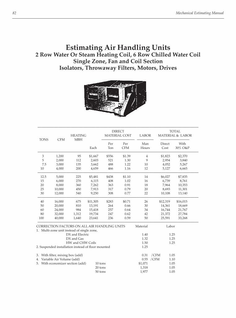
82 Mechanical Estimating Manual
Estimating Air Handling Units2 Row Water Or Steam Heating Coil, 6 Row Chilled Water Coil
Single Zone, Fan and Coil SectionIsolators, Throwaway Filters, Motors, Drives
——————————————————————————————————————— DIRECT TOTAL HEATING MATERIAL COST LABOR MATERIAL & LABOR TONS CFM MBH ———————— ———— ——————— Per Per Man Direct With Each Ton CFM Hours Cost 30% O&P
——————————————————————————————————————— 3 1,200 95 $1,667 $556 $1.39 4 $1,823 $2,370 5 2,000 112 2,603 521 1.30 9 2,954 3,840 7.5 3,000 135 3,662 488 1.22 10 4,052 5,267 10 4,000 200 4,659 466 1.16 12 5,127 6,665
——————————————————————————————————————— 12.5 5,000 225 $5,481 $438 $1.10 14 $6,027 $7,835 15 6,000 270 6,115 408 1.02 16 6,739 8,761 20 8,000 360 7,262 363 0.91 18 7,964 10,353 25 10,000 450 7,913 317 0.79 20 8,693 11,301 30 12,000 540 9,250 308 0.77 22 10,108 13,140
——————————————————————————————————————— 40 16,000 675 $11,305 $283 $0.71 26 $12,319 $16,015 50 20,000 810 13,191 264 0.66 30 14,361 18,669 60 24,000 984 15,418 257 0.64 34 16,744 21,767 80 32,000 1,312 19,734 247 0.62 42 21,372 27,784 100 40,000 1,640 23,641 236 0.59 50 25,591 33,268
——————————————————————————————————————— CORRECTION FACTORS ON ALL AIR HANDLING UNITS Material Labor 1. Multi-zone unit instead of single zone, DX and Electric 1.40 1.25 DX and Gas 1.32 1.25 HW and CHW Coils 1.50 1.25 2. Suspended installation instead of fl oor mounted 1.25
3. With fi lter, mixing box (add) 0.31 /CFM 1.05 4. Variable Air Volume (add) 0.55 /CFM 1.10 5. With economizer section (add) 10 tons $1,071 1.05 20 tons 1,318 1.05 50 tons 1,977 1.05

HVAC Units and Air Distribution Equipment 83
Self Contained Air Conditioning UnitsAir Cooled, DX Coil, Condenser Section,Electric Heating Coil, Supply Fan, Filters
——————————————————————————————————————— DIRECT TOTAL HEATING MATERIAL COST LABOR MATERIAL & LABOR TONS CFM MBH ———————— ———— ——————— Per Per Man Direct With Each Ton CFM Hours Cost 30% O&P
——————————————————————————————————————— 3 1,200 94 $3,212 $1,071 $2.68 6 $3,446 $4,480
5 2,000 115 3,691 738 1.85 12 4,159 5,407
7.5 3,000 135 5,292 706 1.76 14 5,838 7,589
10 4,000 200 6,783 678 1.70 15 7,368 9,579———————————————————————————————————————
12.5 5,000 225 8,352 668 1.67 18 9,054 11,770
15 6,000 270 9,868 658 1.64 20 10,648 13,842
20 8,000 360 12,915 646 1.61 22 13,773 17,905
25 10,000 450 15,204 608 1.52 24 16,140 20,982———————————————————————————————————————
30 12,000 540 17,473 582 1.46 26 18,487 24,033
40 16,000 675 21,584 540 1.35 31 22,793 29,631
50 20,000 810 25,097 502 1.25 36 26,501 34,451
60 24,000 985 29,808 497 1.24 42 31,446 40,880———————————————————————————————————————
CORRECTION FACTORS Material Labor 1. Water cooled 2. Water or steam heating coils. Direct labor costs are $39.00 per hour.

84 Mechanical Estimating Manual
Room Heating and CoolingUnit Ventilators
2 Pipe, Single Coil, Controls, Filters, Floor Mounted
———————————————————————————————————— DIRECT TOTAL MATERIAL COST LABOR MATERIAL & LABOR BtuH —————————— ———— —————————— COOLING Per Man Direct With Each Btu Hours Cost 30% O&P
———————————————————————————————————— 6,000 $1,924 $0.321 5.0 $2,119 $2,755 9,000 1,961 0.218 5.5 2,176 2,828 12,000 2,109 0.176 6.1 2,347 3,051 18,000 2,294 0.127 7.0 2,567 3,337 24,000 2,620 0.109 9.3 2,982 3,877
———————————————————————————————————— 30,000 2,997 0.100 11.5 3,446 4,479 36,000 3,071 0.085 13.2 3,586 4,662 42,000 3,182 0.076 18.0 3,884 5,049 48,000 3,293 0.069 23.2 4,198 5,457 60,000 3,959 0.066 37.0 5,402 7,023
———————————————————————————————————— CORRECTION FACTORS 1. 4 pipe, 2 coil, heating and cooling, +14%. 2. For separate electric heating coil, +30%. 3. Ceiling hung unit ventilators, +5%.

HVAC Units and Air Distribution Equipment 85
Estimating Centrifugal FansAir Foil Wheels, Single Width Single Inlet
Outlet Velocity 2000 FPMIncludes Motors, Drives, Isolators
——————————————————————————————————————— DIRECT TOTAL WHEEL MATERIAL COST LABOR MATERIAL & LABOR TONS CFM DIAMETER ——————— ———— ———————— Per Per Man Direct With Each Ton CFM Hours Cost 30% O&P
——————————————————————————————————————— 1,000 1/3 12 1” $753 $0.75 3 $870 $1,131 2,000 1/2 15 1” 1,358 0.68 7 1,631 2,120 4,000 2 18 1” 1,807 0.45 10 2,197 2,856 6,000 2-1/2 22 1-1/2” 2,260 0.38 12 2,728 3,546 8,000 3 27 1-1/2’ 2,863 0.36 14 3,409 4,432 10,000 5 30 2” 3,391 0.34 16 4,015 5,219
——————————————————————————————————————— 12,000 7-1/2 33 2” 3,988 0.33 18 4,690 6,097 14,000 7-1/2 33 2” 4,747 0.34 20 5,527 7,185 16,000 7-1/2 36-1/2 2” 5,126 0.32 22 5,984 7,779 18,000 10 40-1/4 2” 5,766 0.32 24 6,702 8,712 20,000 10 44-1/4 2” 6,029 0.30 26 7,043 9,156
——————————————————————————————————————— 25,000 15 44-1/4 2-1/2” 7,537 0.30 30 8,707 11,320 30,000 20 54-1/4 2-1/2” 9,044 0.30 36 10,448 13,583 40,000 25 60 2-1/2” 11,305 0.28 46 13,099 17,029 50,000 30 66 3” 14,133 0.28 56 16,317 21,212 60,000 40 73 3” 16,959 0.28 64 19,455 25,291
———————————————————————————————————————
Estimating Utility SetsForward Curve Wheels, Single Width Single Inlet
Includes Motors, Drives, Isolators
——————————————————————————————————————— DIRECT TOTAL WHEEL MATERIAL COST LABOR MATERIAL & LABOR TONS CFM DIAMETER ——————— ———— ———————— Per Per Man Direct With Each Ton CFM Hours Cost 30% O&P
——————————————————————————————————————— 500 1/4 10 1/2” $376 $0.75 2 $454 $590
1,000 1/2 12 3/4” 639 0.64 4 795 1,033
2,000 1 12 1” 1,054 0.53 5 1,249 1,624
4,000 2 18 1” 1,205 0.30 7 1,478 1,922
6,000 3 24 1-1/4” 1,695 0.28 9 2,046 2,659
8,000 5 27 1-1/2” 1,959 0.24 10 2,349 3,054
10,000 5 30 1-1/2” 2,260 0.23 12 2,728 3,546———————————————————————————————————————
12,000 5 33 1-1/2” 2,712 0.23 14 3,258 4,235
14,000 7-1/2 36 1-1/2” 3,165 0.23 16 3,789 4,925
16,000 7-1/2 39 1-1/2” 3,315 0.21 18 4,017 5,223
18,000 10 40 1-1/2” 3,731 0.21 20 4,511 5,864
20,000 15 44 1-1/2” 4,145 0.21 22 5,003 6,504———————————————————————————————————————

86 Mechanical Estimating Manual
Estimating Roof Exhaust FansCentrifugal, Belt Driven, Aluminum Housing
1/2” Static Pressure with Shutter, Birdscreen, Curb
——————————————————————————————————————— DIRECT TOTAL WHEEL MATERIAL COST LABOR MATERIAL & LABOR TONS CFM DIAMETER ———————— ———— ———————— Per Man Direct With Each CFM Hours Cost 30% O&P
——————————————————————————————————————— 500 1/12 10 $665 $1.33 3 $782 $1,017 1,000 1/6 12 793 0.79 3 910 1,183 1,500 1/4 14 797 0.53 3 914 1,189 2,000 1/3 22 980 0.49 4 1,136 1,477
——————————————————————————————————————— 3,000 1/2 24 1,110 0.37 4 1,266 1,645 4,000 3/4 24 1,281 0.32 5 1,476 1,918 6,000 1 30 1,525 0.25 6 1,759 2,287 8,000 1-1/2 30 1,807 0.23 6 2,041 2,653
——————————————————————————————————————— 10,000 2 36 2,203 0.22 7 2,476 3,218 15,000 3 48 3,308 0.22 8 3,620 4,706 20,000 5 48 4,554 0.23 9 4,905 6,377
———————————————————————————————————————
Estimating Vane Axial FansAutomatic Controllable Pitch, Direct Drive
Includes Inlet Cones, T-Frame Motors, Horizontal Supports,Isolators, Pneumatic Actuator
————————————————————————————————————————————— DIRECT TOTAL FAN INCHES MATERIAL COST LABOR MATERIAL & LABOR CFM HP SIZE STATIC ———————— ——— ————————— PRESSURE Per Man Direct With Each CFM Hours Cost 30% O&P
————————————————————————————————————————————— Supply Fans Medium Pressure, 1,770 RPM 20,000 30 36/26 5 $13,490 $0.67 22 $14,348 $18,653 40,000 50 42/26 5 15,097 0.38 32 16,345 21,249 60,000 100 48/26 6 18,752 0.31 44 20,468 26,608 80,000 150 48/26 6 21,357 0.27 48 23,229 30,198 110,000 200 54/26 6 26,513 0.24 64 29,009 37,711 Return Air Fans, 1,170 RPM 18,000 10 38/26 2 12,712 0.71 20 13,492 17,540 36,000 20 45/26 2 14,064 0.39 36. 15,468 20,108 54,000 30 54/26 2 15,815 0.29 48 17,687 22,993 72,000 50 54/26 2 17,262 0.24 50 19,212 24,976 100,000 75 60/26 2 22,132 0.22 64 24,628 32,017
————————————————————————————————————————————— Above fan selection and prices based on Joy vane-axial fans
Direct Labor costs are $39.00 per hour.
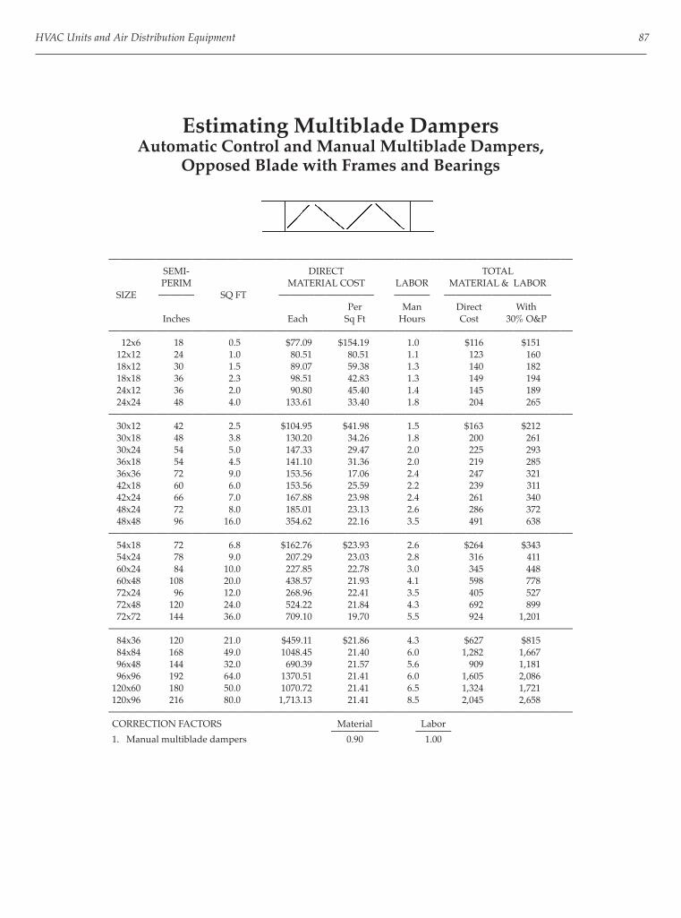
HVAC Units and Air Distribution Equipment 87
Estimating Multiblade DampersAutomatic Control and Manual Multiblade Dampers,
Opposed Blade with Frames and Bearings
——————————————————————————————————————— SEMI- DIRECT TOTAL PERIM MATERIAL COST LABOR MATERIAL & LABOR SIZE ——— SQ FT ———————— ——— ————————— Per Man Direct With Inches Each Sq Ft Hours Cost 30% O&P
——————————————————————————————————————— 12x6 18 0.5 $77.09 $154.19 1.0 $116 $151 12x12 24 1.0 80.51 80.51 1.1 123 160 18x12 30 1.5 89.07 59.38 1.3 140 182 18x18 36 2.3 98.51 42.83 1.3 149 194 24x12 36 2.0 90.80 45.40 1.4 145 189 24x24 48 4.0 133.61 33.40 1.8 204 265
——————————————————————————————————————— 30x12 42 2.5 $104.95 $41.98 1.5 $163 $212 30x18 48 3.8 130.20 34.26 1.8 200 261 30x24 54 5.0 147.33 29.47 2.0 225 293 36x18 54 4.5 141.10 31.36 2.0 219 285 36x36 72 9.0 153.56 17.06 2.4 247 321 42x18 60 6.0 153.56 25.59 2.2 239 311 42x24 66 7.0 167.88 23.98 2.4 261 340 48x24 72 8.0 185.01 23.13 2.6 286 372 48x48 96 16.0 354.62 22.16 3.5 491 638
——————————————————————————————————————— 54x18 72 6.8 $162.76 $23.93 2.6 $264 $343 54x24 78 9.0 207.29 23.03 2.8 316 411 60x24 84 10.0 227.85 22.78 3.0 345 448 60x48 108 20.0 438.57 21.93 4.1 598 778 72x24 96 12.0 268.96 22.41 3.5 405 527 72x48 120 24.0 524.22 21.84 4.3 692 899 72x72 144 36.0 709.10 19.70 5.5 924 1,201
——————————————————————————————————————— 84x36 120 21.0 $459.11 $21.86 4.3 $627 $815 84x84 168 49.0 1048.45 21.40 6.0 1,282 1,667 96x48 144 32.0 690.39 21.57 5.6 909 1,181 96x96 192 64.0 1370.51 21.41 6.0 1,605 2,086 120x60 180 50.0 1070.72 21.41 6.5 1,324 1,721 120x96 216 80.0 1,713.13 21.41 8.5 2,045 2,658
——————————————————————————————————————— CORRECTION FACTORS Material Labor ———— ——— 1. Manual multiblade dampers 0.90 1.00

88 Mechanical Estimating Manual
Estimating Fire DampersCurtain Type Blades, Vertical Installation
——————————————————————————————————————— SEMI- DIRECT TOTAL PERIM MATERIAL COST LABOR MATERIAL & LABOR SIZE ——— SQ FT ———————— ——— ————————— Per Man Direct With Inches Each Sq Ft Hours Cost 30% O&P
——————————————————————————————————————— 12x6 18 0.5 $25.93 $51.86 1.0 $65 $84 12x12 24 1.0 29.13 29.13 1.1 72 94 18x12 30 1.5 38.54 25.69 1.3 89 116 18x18 36 2.3 49.68 21.60 1.3 100 130 24x12 36 2.0 45.24 22.62 1.4 100 130 24x24 48 4.0 75.38 18.84 1.8 146 189
——————————————————————————————————————— 30x12 42 2.5 $52.26 $20.90 1.5 $111 $144 30x18 48 3.8 71.62 18.85 1.8 142 184 30x24 54 5.0 94.23 18.85 2.0 172 224 36x18 54 4.5 80.94 17.99 2.0 159 207 36x36 72 9.0 123.36 13.71 2.4 217 282 42x24 66 7.0 106.06 15.15 2.4 200 260 48x24 72 8.0 114.43 14.30 2.6 216 281 48x48 96 16.0 191.88 11.99 3.5 328 427
——————————————————————————————————————— 54x18 72 6.8 $103.10 $15.16 2.6 $204 $266 54x24 78 9.0 123.36 13.71 2.8 233 302 60x24 84 10.0 133.61 13.36 3.0 251 326 60x48 108 20.0 226.14 11.31 4.1 386 502
——————————————————————————————————————— CORRECTION FACTORS Material Labor ———— ——— 1. U.L. Labels 1.10 --- 2. Horizontal installation 1.20 --- 3. 22 ga. U.L. sleeve 1.40 1.20 4. 22 ga. U.L. sleeve, free area 1.60 1.25 5. Cap for blades out of air stream 1.25 1.25 6. Multiblade type fi re dampers, parallel blades Material factor of 1.1 times MULTIBLADE CONTROL DAMPER prices.

HVAC Units and Air Distribution Equipment 89
Estimating LouversExtruded Aluminum, 4” Deep, Fixed Blade,
Storm Proof with Screens, Mill Finish
——————————————————————————————————————— SEMI- DIRECT TOTAL PERIM MATERIAL COST LABOR MATERIAL & LABOR SIZE ——— SQ FT ———————— ——— ————————— Per Man Direct With Inches Each Sq Ft Hours Cost 30% O&P
——————————————————————————————————————— 12x6 18 0.5 $48.48 $96.97 1.1 $91 $119 12x12 24 1.0 56.57 56.57 1.2 103 134 18x12 30 1.5 78.80 52.53 1.3 129 168 18x18 36 2.3 107.80 46.87 1.5 166 216 24x12 36 2.0 96.97 48.48 1.5 155 202 24x18 42 3.0 130.91 43.64 2.0 209 272
——————————————————————————————————————— 30x12 42 2.5 $115.14 $46.06 2.0 $193 $251 30x18 48 3.8 147.39 38.79 2.1 229 298 30x24 54 5.0 169.70 33.94 2.3 259 337 36x18 54 4.5 163.63 36.36 2.3 253 329 36x36 72 9.0 255.27 28.36 2.6 357 464 42x18 60 6.0 193.94 32.32 2.4 288 374 42x24 66 7.0 217.20 31.03 2.6 319 414 48x24 72 8.0 237.26 29.66 2.8 346 450 48x48 96 16.0 404.69 25.29 4.0 561 729
——————————————————————————————————————— 54x18 72 6.8 $208.81 $30.71 2.8 $318 $413 54x24 78 10.0 269.89 26.99 3.3 399 518 60x24 84 10.0 269.89 26.99 3.5 406 528 60x48 108 20.0 488.07 24.40 4.5 664 863 72x24 96 12.0 310.30 25.86 4.0 466 606 72x48 120 24.0 566.31 23.60 5.0 761 990 72x72 144 36.0 843.63 23.43 6.0 1,078 1,401
——————————————————————————————————————— 84x36 120 21.0 $509.09 $24.24 5.0 $704 $915 84x84 168 49.0 1,148.29 23.43 7.0 1,421 1,848 96x48 144 32.0 749.90 23.43 6.0 984 1,279 96x96 192 64.0 1,499.80 23.43 8.0 1,812 2,355 120x60 180 50.0 1,171.72 23.43 7.5 1,464 1,903 120x96 216 80.0 1,874.75 23.43 9.0 2,226 2,893
——————————————————————————————————————— Labor based on scaffold height installation in basement or on 1st fl oor or man height installation in penthouse wall.
CORRECTION FACTORS Material Labor ———— ——— 1. Galvanized 1.20 2. Finishes: baked enamel add $3.51 /sq ft anodized, add 4.41 /sq ft duranodic, add 7.90 /sq ft fl uoropolymer coating, add 12.17 /sq ft

90 Mechanical Estimating Manual
Estimating RegistersReturn Air Registers, Fixed 450 Vanes,
Opposed Blade Dampers, Commercial Grade
——————————————————————————————————————— SEMI- DIRECT TOTAL PERIM MATERIAL COST LABOR MATERIAL & LABOR SIZE ——— SQ FT ———————— ——— ————————— Per Man Direct With Inches Each Sq Ft Hours Cost 30% O&P
——————————————————————————————————————— 12x6 18 0.5 $30.83 $61.66 0.8 $62 $81 12x12 24 1.0 40.27 40.27 0.9 75 98 18x12 30 1.5 54.66 36.44 1.0 94 122 18x18 36 2.3 74.89 32.56 1.1 118 153 24x12 36 2.0 65.09 32.55 1.1 108 140 24x24 48 4.0 123.36 30.84 1.3 174 226
——————————————————————————————————————— 30x12 42 2.5 $82.44 $32.97 1.2 $129 $168 30x18 48 3.8 121.09 31.87 1.3 172 223 30x24 54 5.0 149.91 29.98 1.5 208 271 36x18 54 4.5 136.90 30.42 1.5 195 254 36x36 72 9.0 250.28 27.81 1.7 317 412 42x24 66 7.0 202.67 28.95 1.6 265 345 48x24 72 8.0 226.14 28.27 1.7 292 380 48x48 96 16.0 484.82 30.30 2.6 586 762
——————————————————————————————————————— 54x18 72 6.8 $197.02 $28.97 1.7 $263 $342 54x24 78 9.0 251.33 27.93 2.0 329 428 60x24 84 10.0 290.61 29.06 2.3 380 494 60x48 108 20.0 531.07 26.55 3.0 648 842
——————————————————————————————————————— CORRECTION FACTORS—Commercial Grades Material Labor ———— ——— 1. Supply registers, single defl ection dampers .......... 1.10 1.00 2. Supply registers, double defl ection dampers ........ 1.25 1.00 3. Transfer grille, single defl ection, no dampers ........ 0.63 0.60 4. Relief grille in ceiling, lay in, single defl ection, no dampers .................................. 0.63 0.40 5. Aluminum construction instead of steel ................ 1.10 1.00 6. Lay in type grilles ....................................................... 1.00 0.50 7. Side wall screw in ...................................................... 1.00 0.65 8. Residential light commercial grade ......................... 0.60 0.95
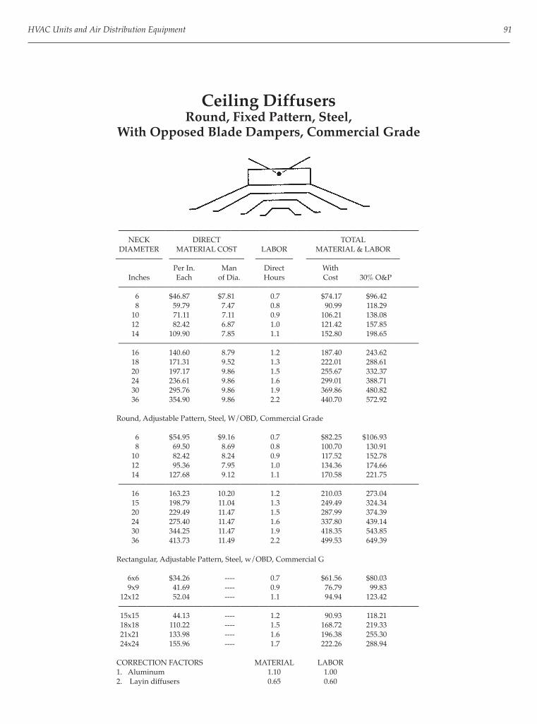
HVAC Units and Air Distribution Equipment 91
Ceiling DiffusersRound, Fixed Pattern, Steel,
With Opposed Blade Dampers, Commercial Grade
———————————————————————————————— NECK DIRECT TOTAL DIAMETER MATERIAL COST LABOR MATERIAL & LABOR ————— ———————— ———— —————————— Per In. Man Direct With Inches Each of Dia. Hours Cost 30% O&P
———————————————————————————————— 6 $46.87 $7.81 0.7 $74.17 $96.42 8 59.79 7.47 0.8 90.99 118.29 10 71.11 7.11 0.9 106.21 138.08 12 82.42 6.87 1.0 121.42 157.85 14 109.90 7.85 1.1 152.80 198.65
———————————————————————————————— 16 140.60 8.79 1.2 187.40 243.62 18 171.31 9.52 1.3 222.01 288.61 20 197.17 9.86 1.5 255.67 332.37 24 236.61 9.86 1.6 299.01 388.71 30 295.76 9.86 1.9 369.86 480.82 36 354.90 9.86 2.2 440.70 572.92
Round, Adjustable Pattern, Steel, W/OBD, Commercial Grade
6 $54.95 $9.16 0.7 $82.25 $106.93 8 69.50 8.69 0.8 100.70 130.91 10 82.42 8.24 0.9 117.52 152.78 12 95.36 7.95 1.0 134.36 174.66 14 127.68 9.12 1.1 170.58 221.75
———————————————————————————————— 16 163.23 10.20 1.2 210.03 273.04 15 198.79 11.04 1.3 249.49 324.34 20 229.49 11.47 1.5 287.99 374.39 24 275.40 11.47 1.6 337.80 439.14 30 344.25 11.47 1.9 418.35 543.85 36 413.73 11.49 2.2 499.53 649.39
Rectangular, Adjustable Pattern, Steel, w/OBD, Commercial G
6x6 $34.26 ---- 0.7 $61.56 $80.03 9x9 41.69 ---- 0.9 76.79 99.83 12x12 52.04 ---- 1.1 94.94 123.42
———————————————————————————————— 15x15 44.13 ---- 1.2 90.93 118.21 18x18 110.22 ---- 1.5 168.72 219.33 21x21 133.98 ---- 1.6 196.38 255.30 24x24 155.96 ---- 1.7 222.26 288.94
CORRECTION FACTORS MATERIAL LABOR 1. Aluminum 1.10 1.00 2. Layin diffusers 0.65 0.60

92 Mechanical Estimating Manual
VAV Terminal BoxesCooling Only with Pneumatic or Electric Motor, Controls
——————————————————————————————————————— DIRECT COIL DIRECT LABOR MATERIAL & LABOR CFM RANGE SQ FT MATERIAL ———— —————————— COST Man Direct With Hours Cost 30% O&P
——————————————————————————————————————— 200 - 400 ---- $335.55 2.0 $414 $538 400 - 600 ---- 395.57 2.7 501 651 600 - 800 ---- 460.22 3.3 589 766 800 - 1,000 ---- 511.01 4.0 667 867
——————————————————————————————————————— 1,000 - 1,500 ---- 569.50 4.5 745 969 1,500 - 2,000 ---- 638.77 5.0 834 1,084 2,000 - 3,000 ---- 692.64 5.5 907 1,179
———————————————————————————————————————
VAV Terminal BoxesWith Reheat Coils, Pneumatic or Electric Motor, Controls
——————————————————————————————————————— DIRECT COIL DIRECT LABOR MATERIAL & LABOR CFM RANGE SQ FT MATERIAL ———— —————————— COST Man Direct With Hours Cost 30% O&P
——————————————————————————————————————— 200 - 400 0.8 $484.85 2.7 $590 $767 400 - 600 1.0 557.19 2.9 670 871 600 - 800 1.5 671.09 3.6 811 1,055 800 - 1,000 2.0 737.28 4.3 905 1,176
——————————————————————————————————————— 1,000 - 1,500 2.5 912.75 4.9 1,104 1,435 1,500 - 2,000 3.0 1005.10 5.5 1,220 1,585 2,000 - 3,000 3.5 1089.75 6.0 1,324 1,721
———————————————————————————————————————
VAV System Components TITUS VAV BOX RETROFIT KITS Cost each ———— 1. For Buensod or Tutle and Baily CAV boxes up to 1,000 CFM ..........................................................$370
2. Titus kits for Titus boxes 0 - 500 CFM ..................................................................$266 500 - 1,000 CFM ...........................................................$370
CARRIER VAV UNITS 1. Moduline cooling only VAV boxes with 3 slot diffusers .....................................................$252
VAV CONTROL PANELS 1. Controls and monitors supply fans, return fans, static pressure sensor, supply and return air, air monitoring stations, transmitters, outside air control ............................................... $8,880 to $14,800
2. Static pressure regulator .......................................................................................................................$222

HVAC Units and Air Distribution Equipment 93
VAV Ceiling Diffusers
——————————————————————————————————————— DIRECT DIRECT COST LABOR MATERIAL & LABOR DIA. CFM ————— ———— —————————— Man Direct With Inches Range Each Hours Cost 30% O&P
——————————————————————————————————————— 6 100-220 $252 2 $330 $428 8 160-355 252 2 330 428 10 260-580 252 2 330 428 12 380-890 252 2 330 428
——————————————————————————————————————— Self contained variable volume ceiling diffusers with thermal sensors for discharge air and warm-up, built in volume controls and built in pressure sensor for automatic switch-over between cooling and heating.
Manufacturers 1. Therma-Fuser by Acutherm, Novato, CA.
Direct labor costs are $39.00 per hour.
Inlet Vane DampersFor Centrifugal Fans
——————————————————————————————————————— DIRECT TOTAL DIA. AREA MATERIAL COST LABOR MATERIAL & LABOR ——— ——— ———————— ——— ————————— Per Man Direct With Inches Sq ft Each Sq Ft Hours Cost 30% O&P
——————————————————————————————————————— 18 1.8 $104 $57.72 1.5 $162 $211 20 2.2 114 51.80 1.7 180 234 22 2.6 126 48.54 1.9 200 260 24 3.1 140 45.14 2.0 218 283 26 3.7 153 41.44 2.2 239 311 28 4.3 173 40.33 2.3 263 342 30 5.0 190 38.07 2.4 284 369 33 6.0 214 35.66 2.6 315 410 36 7.1 242 34.04 2.8 351 456 39 8.3 270 32.56 3.1 391 508
——————————————————————————————————————— 42 9.6 298 31.08 3.3 427 555 45 11.0 326 29.60 3.5 462 601 48 12.6 354 28.12 4.0 510 663 54 16.0 424 26.47 4.6 603 784 60 19.6 516 26.33 5.3 723 940 66 23.8 609 25.60 6.0 843 1,096 72 28.2 712 25.25 6.5 966 1,255 78 33.2 831 25.04 7.1 1,108 1,441 84 38.5 963 25.01 7.6 1,259 1,637 90 44.1 1,099 24.92 7.8 1,403 1,824 96 50.3 1,243 24.72 8.0 1,555 2,022
——————————————————————————————————————— Direct labor costs are $39.00 per hour.

94 Mechanical Estimating Manual
Fixed Pitch Sheaves
———————————————————————————————————— DIRECT TOTAL PITCH MATERIAL COST LABOR MATERIAL & LABOR DIA. —————————— ———— —————————— B BELTS Man Direct With Pulley Bushing Hours Cost 30% O&P
———————————————————————————————————— FIXED, SINGLE GROOVE, NO BUSHING 1.9 $8.88 ---- 0.2 $16.68 $21.68 2.3 9.21 ---- 0.2 17.01 22.11 2.6 9.95 ---- 0.3 21.65 28.14 3.0 10.82 ---- 0.3 22.52 29.27 3.2 13.59 ---- 0.4 29.19 37.94 3.4 14.65 ---- 0.4 30.25 39.33 3.9 15.47 ---- 0.4 31.07 40.39 4.6 17.23 ---- 0.5 36.73 47.75
FIXED, DOUBLE GROOVE, BUSHINGS 3.4 $27.08 15.688 0.4 $58.37 $75.88 3.8 29.48 15.688 0.4 60.77 79.00 4.6 36.72 15.688 0.4 68.01 88.41 4.8 37.70 15.688 0.4 68.98 89.68 5.4 41.53 15.688 0.4 72.82 94.66 5.8 44.09 15.688 0.5 79.28 103.06 6.4 47.89 15.688 0.5 83.08 108.01 6.8 49.20 15.688 0.5 84.38 109.70 7.0 49.49 15.688 0.5 84.68 110.08 8.0 50.72 15.688 0.6 89.81 116.75 9.0 52.61 15.688 0.6 91.70 119.21 11.0 62.34 15.688 0.6 101.43 131.85 12.4 67.33 15.688 0.7 110.31 143.41 13.6 80.14 15.688 0.7 123.13 160.07 15.4 110.59 15.688 0.7 153.57 199.65 18.4 146.43 15.688 0.7 189.42 246.24
FIXED, TRIPLE GROOVE, BUSHINGS 3.4 $30.01 15.688 0.4 $61.30 $79.69 3.8 33.36 15.688 0.4 64.65 84.04 4.0 34.56 15.688 0.4 65.85 85.60 4.4 37.12 15.688 0.4 68.41 88.93 4.8 44.09 15.688 0.4 75.38 97.99 5.0 45.30 15.688 0.5 80.49 104.64 5.4 39.77 15.688 0.5 74.96 97.44 5.8 42.46 15.688 0.5 77.65 100.94 6.0 43.72 15.688 0.5 78.91 102.58 6.4 47.43 15.688 0.6 86.52 112.48 6.8 49.91 15.688 0.6 88.99 115.69 7.0 55.87 15.688 0.6 94.96 123.45 8.0 59.61 15,688 0.6 98.70 128.31 9.0 67.13 15.688 0.6 106.22 138.09 11.0 82.67 15.688 0.7 125.66 163.36 12.4 95.52 15.688 0.7 138.51 180.06 13.6 102.89 15.688 0.7 145.88 189.64 15.4 131.26 15.688 0.7 174.25 226.52 18.4 158.98 15.688 0.7 201.97 262.56
———————————————————————————————————— Direct labor costs are $39.00 per-hour.

HVAC Units and Air Distribution Equipment 95
Variable Pitch Sheaves———————————————————————————————
TOTAL PITCH DIRECT LABOR MATERIAL & LABOR DIA. COST ———— —————————— B BELTS Man Direct With Hours Cost 30% O&P
——————————————————————————————— VARIABLE PITCH SINGLE GROOVE 2.4-3.2 $9.06 0.4 $24.66 $32.05 2.7-3.7 11.96 0.4 27.56 35.83 3.1-4.1 14.13 0.4 29.73 38.65 3.7-4.7 32.19 0.5 51.69 67.20 4.3-5.3 43.51 0.5 63.01 81.92 4.9-5.9 53.12 0.6 76.52 99.47 5.5-6.5 55.26 0.6 78.66 102.26 VARIABLE PITCH, DOUBLE GROOVE 2.5-3.3 $42.11 0.5 $61.61 $80.09 2.9-3.9 48.19 0.5 67.69 88.00 3.7-4.7 55.50 0.6 78.90 102.57 4.3-5.3 65.42 0.6 88.82 115.46 4.9-5.9 83.49 0.7 110.79 144.02 5.5-6.5 89.47 0.7 116.77 151.80
——————————————————————————————— Direct labor costs are $39.00 per hour.
V-Belts———————————————————————————————
DIRECT TOTAL COST LABOR MATERIAL & LABOR DIA. ———— ———— —————————— Man Direct With Each Hours Cost 30% O&P
——————————————————————————————— 33 $6.62 0.1 $10.52 $13.67 38 7.24 0.1 11.14 14.48 43 8.23 0.1 12.13 15.77 47 9.06 0.1 12.96 16.84 53 9.99 0.2 17.79 23.13
——————————————————————————————— 57 10.43 0.2 18.23 23.70 63 10.83 0.2 18.63 24.22 67 11.54 0.2 19.34 25.15 73 12.24 0.3 23.94 31.12 76 12.54 0.3 24.24 31.51 83 13.94 0.3 25.64 33.33 86 14.58 0.3 26.28 34.16
——————————————————————————————— 93 15.47 0.4 31.07 40.39 96 16.16 0.4 31.76 41.29 103 17.27 0.4 32.87 42.73 106 17.69 0.4 33.29 43.27 108 18.12 0.5 37.62 48.90 111 18.72 0.5 38.22 49.69
——————————————————————————————— 115 19.58 0.5 39.08 50.80 123 20.54 0.5 40.04 52.06 131 21.90 0.6 45.30 58.90 139 23.53 0.6 46.93 61.01 147 24.91 0.6 48.31 62.80 161 27.07 0.6 50.47 65.61 176 29.54 0.6 52.94 68.82
——————————————————————————————— Direct labor costs are $39.00 per hour.

96 Mechanical Estimating Manual
Filter Labor
HOURS EACH
THROW AWAY AND PERMANENT FILTERS
Slid Into Channels, I” or 2” thick 0.1
Assembled Into Filter Bank 0.5
GREASE FILTERS 0.2
(Laid in place in kitchen hood)
BAG TYPE CARTRIDGES WITH FRAME
(Shipped Unassembled)
18x18 2.0
24x24 2.0
30x30 2.5
HEPA. FILTER CARTRIDGES
24x12x6 deep 2.0
24x12x12 deep 2.4
24x24x6 deep 2.4
24x24x12 deep 2.8
CHARCOAL FILTER CARTRIDGES
12x12 1.5
24x12 2.0
24x24 2.5
ROLL TYPE FILTER UNITS
(Shipped Unassembled)
One section up to 5 ft. wide 12.0
Two section fi lter bank 21.0
ELECTRO-STATIC FILTER UNITS
24x12 2.0
24x24 2.5
36x24 4.0
48x36 8.0
60x48 12.0
72x60 14.0
84x72 16.0

97
Chapter 7
Plumbing Fixtures and Specialties
This chapter contains labor tables for plumbing fi xtures such as:
• Lavatories and Sinks• Toilets and Urinals• Drinking Fountains• Tubs and Showers• Kitchen Products• Fire Protection Equipment• Water Meters• Carriers and Supports
In addition, this chapter covers labor tables for plumbing specialties such as:
• Drains: Floor, Roof, Scupper and Gutter types, Floor Cleanouts • Back Flow Preventers
Current and local prices for bidding purposes are to be gotten through quotations from suppliers or from a suppliers pricing manual.
Plumbing FixturesLabor Only
—————————————————————————— Lavatories Labor Wall Hung ....................................................................................3.26 Comer ...........................................................................................4.15 Counter Top .................................................................................3.05
—————————————————————————— Sinks Counter Top .................................................................................4.46 Floor ..............................................................................................5.95 All Purpose ..................................................................................5.28 Instrument ....................................................................................6.75
—————————————————————————— Toilets One Piece Toilet ...........................................................................3.05 Two Piece Toilet ...........................................................................4.00 Wall Hung ....................................................................................4.76 Bidet ..............................................................................................3.05
—————————————————————————— Urinals Wall Hung ....................................................................................4.76 Floor Mounted .............................................................................5.95 Trough ...........................................................................................6.75 Women’s w/FV ...........................................................................5.35
——————————————————————————

98 Mechanical Estimating Manual
Plumbing FixturesLabor Only
—————————————————————————— Drinking Fountains Labor Wall Hung ...........................................................................2.96 Wall Recessed ......................................................................3.27 Freeze Proof ........................................................................3.78 Free Standing ......................................................................4.47
—————————————————————————— Tubs Cast Iron Comer .................................................................7.48 Cast Iron Recessed .............................................................7.48 Cast Iron Square .................................................................7.48
—————————————————————————— Showers One Piece Fiberglass Shower and Tub ............................8.94 32” Square Shower Stall ....................................................7.35 36” Square Shower Stall ....................................................7.48 36” Comer Shower Stall ....................................................7.48
—————————————————————————— Kitchen Products Dishwashing Machine, 45 inch ......................................23.95 Dishwashing Machine, 54 inch ......................................27.90 Dishwashing Machine, 64 inch ......................................32.50 Dishwashing Machine, 80 inch ......................................35.50
Garbage Disposal, 1-1/2 BP ..............................................5.95 Garbage Disposal, 5 Bp .....................................................9.95
Ice Maker, 225 lbs, 24 hours, Air Cooled .........................5.95 Ice Maker, 225 lbs, 24 hours, Water Cooled ....................5.95
——————————————————————————
Plumbing FixturesLabor Only
—————————————————————————— Fire Protection Equipment Labor Fire Hose Cabinet w/Valve & 75’ Hose ...................................3.00 Hose Valve with Cap & Chain ..................................................2.80
—————————————————————————— Fire Pump 500 GPM ............................................................................50.80 750 GPM ............................................................................53.35 1000 GPM ..........................................................................62.20 1500 GPM ..........................................................................69.00 2000 GPM ..........................................................................95.00 2500 GPM ........................................................................104.80 3000 GPM ........................................................................131.50 3500 GPM ........................................................................140.00
—————————————————————————— Fire Extinguishers Manual Pull Station ...........................................................1.25 CO2 High Pressure System 75 Lb Cylinder ...........................................................2.45 100 Lb ..........................................................................2.95 FM200 System 25 Lb Container .........................................................1.85 45 Lb ............................................................................2.15 65 Lb ............................................................................2.45 100 Lb ..........................................................................2.95 200 Lb ..........................................................................2.75
—————————————————————————— Wall Hydrant ...............................................................................4.20
——————————————————————————

Plumbing Fixtures and Specialties 99
Plumbing FixturesLabor Only
—————————————————————————— Water Meters Labor
—————————————————————————— Commercial / Residential—Bronze 1/2” to 1” ..........................................................................0.55 1-1/4” to 2” ......................................................................1.08 3”........................................................................................5.00 4”........................................................................................9.80 6”......................................................................................15.05 8”......................................................................................18.60
—————————————————————————— Carriers / Supports
—————————————————————————— Adjustable Siphon Jet Single Water Closet 4”-5” ..................................................................................1.80 Adjustable Siphon Jet Double Water Closet 4”-6” ..................................................................................3.20 Offset Single Blowout Water Closet 4”........................................................................................1.80 Offset Double Blowout Water Closet 4”........................................................................................3.20 Floor/Wall Mount Urinal .......................................................1.80 Lavatory .....................................................................................1.55 Sink .............................................................................................1.55 Drinking Fountain ...................................................................1.55 Water Coolers ............................................................................1.55
——————————————————————————
Plumbing SpecialtiesLabor Only
—————————————————————————— Drains Labor
—————————————————————————— Floor Drain—Standard 2” Dia ...................................................................................1.32 3” Dia ...................................................................................1.42 4” Dia ...................................................................................1.58 5” Dia ...................................................................................1.79 6” Dia ...................................................................................2.00
—————————————————————————— Roof Drain—Standard 2” Dia ...................................................................................1.58 3” Dia ...................................................................................1.68 4” Dia ...................................................................................1.84 5” Dia ...................................................................................2.10 6” Dia ...................................................................................2.37
—————————————————————————— Scupper Drain—Standard 2” - 4” Dia ............................................................................0.95 5” - 6” Dia ............................................................................1.10
—————————————————————————— Gutter Drain—Standard 2” Dia ...................................................................................1.32 3” Dia ...................................................................................1.42 4” Dia ...................................................................................1.58 5” Dia ...................................................................................1.79 6” Dia ...................................................................................2.00
——————————————————————————

100 Mechanical Estimating Manual
Plumbing SpecialtiesLabor Only
—————————————————————————— Cleanouts Labor
—————————————————————————— Floor Cleanout 2” Dia ...................................................................................0.86 3” Dia ...................................................................................0.92 4” Dia ...................................................................................1.09 5” Dia ...................................................................................1.51 6” Dia ...................................................................................1.70 8” Dia ...................................................................................1.89 Wall Cleanout 2” Dia ...................................................................................0.50 3” Dia ...................................................................................0.53 4” Dia ...................................................................................0.56 5” Dia ...................................................................................0.59 6” Dia ...................................................................................0.61 8” Dia ...................................................................................0.65
—————————————————————————— Backfl ow Preventers
—————————————————————————— Threaded Bronze 3/4” ......................................................................................1.23 1”...........................................................................................1.46 1-1/4” ...................................................................................1.93 1-1/2” ...................................................................................2.16 2”...........................................................................................2.84 Flanged Iron 2-1/2” ...................................................................................4.00 3”...........................................................................................4.39 4”...........................................................................................5.80 6”...........................................................................................8.52 8”.........................................................................................10.33 10”.......................................................................................12.35
——————————————————————————
Plumbing SpecialtiesLabor Only
—————————————————————————— Backfl ow Preventers Labor
—————————————————————————— Union Bronze 3/4” ......................................................................................1.23 1”...........................................................................................1.46
—————————————————————————— Double Check Valve Threaded 3/4” ......................................................................................0.78 1”...........................................................................................0.95 1-1/2” ...................................................................................1.14 2”...........................................................................................1.39
—————————————————————————— Double Check Valve Flanged 2-1/2” ...................................................................................2.41 3”...........................................................................................4.02 4”...........................................................................................5.55 6”...........................................................................................8.07 8”...........................................................................................9.99 1001.....................................................................................12.16
——————————————————————————

101
AIR POLLUTION EQUIPMENT
There are four basic types of collectors, each with its own variations. These are: centrifugal cyclones, baghouses, scrubbers, and electrostatic precipitators. Collectors are rated by the size of particles they can remove, by percentage effi ciency of removal of different size particles, and by permissible temperature ranges, pressure drops, air volumes, and water usage.Cyclones are dry centrifugal collectors that remove particles down to approximately 10 microns at effi ciencies in the 80 to 90 percent region. Particles are removed by centrifugal force and drop down into a hopper while the cleaned air goes out the top of the unit. There are three variations of cyclones. The fi rst is the large diameter, low resistance type, which is most effi cient in the 40 to 60 micron particle size range. The second is the medium effi ciency cyclone, which has a smaller diameter housing and is generally used for 20 to 30 micron sized particles. The third cyclone is the high effi ciency, small diameter model, which is very effi cient in the 10 to 15 micron range. Baghouses are dry collectors that clean like a vacuum cleaner, incorporating a number of tubular, stocking-like fabric fi lter bags. They can collect dry particulates such as dust and fumes only and cannot be used for gases or liquids. They are highly effi cient, reaching a 99.9 percent level on 1 micron size particles, and operate best in the 0.25 micron size range. Pressure losses are higher, around 3 to 8 inch WG, and are dependent on the air-to-
Chapter 8
Air Pollution and Heat Recovery Equipment
cloth ratios involved. There are two basic types of fabric collectors, distinguished by the method of bag cleaning and direction or air fl ow. The mechanical baghouse has motorized shakers to remove dust from the insides of the vertical tubes. The dust laden air fl ows up and into the tubes, then out through the fabric. The other type of baghouse is pneumatically cleaned-air is used to clean the bags rather then mechanical shakers-and there are three variations: reverse air fl ow, reverse jet, and pulse jet. Wet scrubbers can be used for particulates, gases, and liquids. Liquid droplets in a scrubber capture particulates mechanically while gases are removed through absorption. There are a number of different types of scrubbers such as packed towers, venturi, wet centrifugal, wet dynamic, orifi ce types, and fog towers. Effi ciencies range from 90 to 99 percent for particles in the 1 to 5 micron range. Mgh energy scrubbers remove particles in the 0.25 to 1 micron range. Wet scrubbers are often divided into three groups according to pressure losses, theses being 4 to 8, 8 to 25, and 25 to 60 inch WG, respectively. Electrostatic precipitators are used primarily to collect particulates such as welding fumes and some mists. Effi ciencies are in the 98 to 99 percent range for 0.25 to 1 micron particles. A precipitator employs an ionization process whereby incoming particles are made negative and then collected on a positive plate through magnetic attraction. The collector plate is periodically cleaned by rapping, causing the particles to fall away by gravity.
Four basic types of collectors
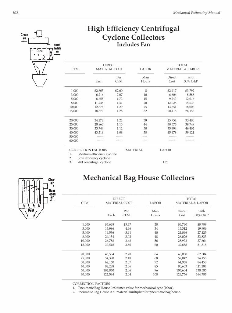
102 Mechanical Estimating Manual
High Effi ciency CentrifugalCyclone Collectors
Includes Fan
—————————————————————————————————— DIRECT TOTAL CFM MATERIAL COST LABOR MATERIAL & LABOR ————— ———————— ———— ————————— Per Man Direct with Each CFM Hours Cost 30% O&P
—————————————————————————————————— 1,000 $2,605 $2.60 8 $2,917 $3,792 3,000 6,216 2.07 10 6,606 8,588 5,000 8,658 1.73 15 9,243 12,016 8,000 11,248 1.41 20 12,028 15,636 10,000 12,876 1.29 25 13,851 18,006 15,000 18,870 1.26 32 20,118 26,153
—————————————————————————————————— 20,000 24,272 1.21 38 25,754 33,480 25,000 28,860 1.15 44 30,576 39,749 30,000 33,744 1.12 50 35,694 46,402 40,000 43,216 1.08 58 45,478 59,121 50,000 ------ ------ ---- ------- -------- 60,000 ------ ------ ---- ------- --------
—————————————————————————————————— CORRECTION FACTORS MATERIAL LABOR 1. Medium effi ciency cyclone 2. Low effi ciency cyclone 3. Wet centrifugal cyclone 1.25
Mechanical Bag House Collectors
—————————————————————————————————————— DIRECT TOTAL CFM MATERIAL COST LABOR MATERIAL & LABOR ————— ———————— ———— ————————— Per Man Direct with Each CFM Hours Cost 30% O&P
—————————————————————————————————————— 1,000 $5,668 $5.67 28 $6,760 $8,789 3,000 13,986 4.66 34 15,312 19,906 5,000 19,536 3.91 40 21,096 27,425 8,000 24,154 3.02 48 26,026 33,833 10,000 26,788 2.68 56 28,972 37,664 15,000 37,518 2.50 60 39,858 51,815
—————————————————————————————————————— 20,000 45,584 2.28 64 48,080 62,504 25,000 54,390 2.18 68 57,042 74,155 30,000 62,160 2.07 72 64,968 84,458 40,000 82,288 2.06 85 85,603 111,284 50,000 102,860 2.06 96 106,604 138,585 60,000 122,544 2.04 108 126,756 164,783
—————————————————————————————————————— CORRECTION FACTORS 1. Pneumatic Bag House 0.90 times value for mechanical type (labor). 2. Pneumatic Bag House 0.71 material multiplier for pneumatic bag house.

Air Pollution and Heat Recovery Equipment 103
Wet Scrubber Collectors
—————————————————————————————————————— DIRECT TOTAL CFM MATERIAL COST LABOR MATERIAL & LABOR ————— ———————— ———— ————————— Per Man Direct with Each CFM Hours Cost 30% O&P
—————————————————————————————————————— 1,000 22 $1,270 $1,651 3,000 12,965 4.32 28 14,057 18,274 5,000 16,798 3.36 32 18,046 23,460 8,000 20,838 2.60 38 22,320 29,017 10,000 23,532 2.35 45 25,287 32,873 15,000 32,190 2.15 48 34,062 44,281
—————————————————————————————————————— 20,000 39,072 1.95 54 41,178 53,531 25,000 45,880 1.84 58 48,142 62,585 30,000 53,724 1.79 62 56,142 72,985 40,000 69,856 1.75 68 72,508 94,260 50,000 85,100 1.70 76 88,064 114,483 60,000 99,456 1.66 88 102,888 133,754
——————————————————————————————————————
Electrostatic Precipitator Collectors
—————————————————————————————————————— DIRECT TOTAL
CFM MATERIAL COST LABOR MATERIAL & LABOR ————— ———————— ———— ————————— Per Man Direct with Each CFM Hours Cost 30% O&P
—————————————————————————————————————— 1,000 $3,078 $3.08 8 $3,390 $4,408 3,000 8,036 2.68 10 8,426 10,954 5,000 12,062 2.41 15 12,647 16,441 8,000 17,168 2.15 20 17,948 23,332 10,000 19,980 2.00 25 20,955 27,242 15,000 28,416 1.89 32 29,664 38,563
—————————————————————————————————————— 20,000 35,816 1.79 38 37,298 48,487 25,000 43,660 1.75 44 45,376 58,989 30,000 51,060 1.70 50 53,010 68,913 40,000 65,712 1.64 58 67,974 88,366
50,000 80,660 1.61 66 83,234 108,20460,000 96,792 1.61 74 99,678 129,581
——————————————————————————————————————

104 Mechanical Estimating Manual
Industrial Exhaust Fans
—————————————————————————————————————— DIRECT TOTAL CFM MATERIAL COST LABOR MATERIAL & LABOR ————— ———————— ———— ————————— Per Man Direct with Each CFM Hours Cost 30% O&P
—————————————————————————————————————— 1,000 $1,672 $1.67 4.00 $1,828 $2,377 2,000 3,078 1.54 9.00 3,429 4,458 4,000 3,907 0.98 13.00 4,414 5,738 6,000 5,062 0.84 16.00 5,686 7,391 8,000 6,512 0.81 18.00 7,214 9,378 10,000 7,844 0.78 21.00 8,663 11,262
—————————————————————————————————————— 12,000 9,413 0.78 23.00 10,310 13,403 14,000 10,982 0.78 26.00 11,996 15,594 16,000 12,077 0.75 29.00 13,208 17,170 18,000 13,586 0.75 31.00 14,795 19,234 20,000 13,616 0.68 34.00 14,942 19,425
—————————————————————————————————————— 24,000 16,339 0.68 39.00 17,860 23,218 28,000 19,062 0.68 44.00 20,778 27,012 32,000 21,786 0.68 49.00 23,697 30,806 36,000 23,443 0.65 55.00 25,588 33,265 40,000 26,048 0.65 60.00 28,388 36,904
—————————————————————————————————————— CORRECTION FACTORS 1. For suspended fan, +20%. 2. For DWDI fan, +10% 3. For split centrifugal housing, knocked down, +50%. 4. For inlet vane control, +10%. 5. For crane hoist, with fan set directly on pad, -20%.
Gas Fired Makeup Air Units——————————————————————————————————————
DIRECT TOTAL CFM MATERIAL COST LABOR MATERIAL & LABOR ————— ———————— ———— ————————— Per Man Direct with Each CFM Hours Cost 30% O&P
—————————————————————————————————————— 1,000 $1,051 $1.05 6 $1,285 $1,670 2,000 2,072 1.04 12 2,540 3,302 4,000 4,144 1.04 15 4,729 6,148 6,000 6,038 1.01 20 6,818 8,864 8,000 7,933 0.99 22 8,791 11,428 10,000 9,768 0.98 24 10,704 13,915
—————————————————————————————————————— 12,000 11,544 0.96 26 12,558 16,325 14,000 13,261 0.95 29 14,392 18,709 16,000 15,155 0.95 31 16,364 21,273 18,000 16,783 0.93 34 18,109 23,542 20,000 18,352 0.92 36 19,756 25,683
—————————————————————————————————————— 24,000 21,667 0.90 37 23,110 30,043 28,000 25,278 0.90 38 26,760 34,789 32,000 28,416 0.89 42 30,054 39,070 36,000 31,968 0.89 46 33,762 43,891 40,000 34,928 0.87 50 36,878 47,941
——————————————————————————————————————

Air Pollution and Heat Recovery Equipment 105
Air to Air Plate Heat Exchangers
—————————————————————————————————————— DIRECT TOTAL CFM MATERIAL COST LABOR MATERIAL & LABOR ————— ———————— ———— ————————— Per Man Direct with Each CFM Hours Costs 30% O&P
—————————————————————————————————————— 5,000 $8,140 $1.63 12 $8,608 $11,190 10,000 14,252 1.43 15 14,837 19,289 15,000 18,204 1.21 20 18,984 24,679 20,000 19,536 0.98 24 20,472 26,614 25,000 22,200 0.89 25 23,175 30,128
—————————————————————————————————————— ACCESSORIES 1. Face and by-pass section with controls 5,000 CFM $2,516 10,000 CFM $2,960
Direct labor costs are $39.00 per hour.
Heat Exchanger Wheels
—————————————————————————————————————— DIRECT TOTAL CFM MATERIAL COST LABOR MATERIAL & LABOR ————— ———————— ———— ————————— Per Man Direct with Each CFM Hours Costs 30% O&P
—————————————————————————————————————— PACKAGE UNIT 7,000 $51,800 $7.40 15 $52,502 $68,253 10,000 64,380 6.44 26 65,394 85,012 15,000 75,480 5.03 32 76,728 99,746 20,000 81,400 4.07 40 82,960 107,848
—————————————————————————————————————— 25,000 83,250 3.33 41 84,849 110,304 30,000 93,240 3.11 42 94,878 123,341 35,000 106,190 3.03 51 108,179 140,633 40,000 118,400 2.96 55 120,545 156,709 50,000 148,000 2.96 60 150,340 195,442 WHEEL ONLY
7,000 $12,284 $1.75 12 $12,752 $16,578 10,000 16,280 1.63 15 16,865 21,925 15,000 22,200 1.48 20 22,980 29,874 20,000 23,976 1.20 24 24,912 32,386
—————————————————————————————————————— 25,000 24,420 0.98 25 25,395 33,014 30,000 25,752 0.86 26 26,766 34,796 35,000 26,936 0.77 31 28,145 36,589 40,000 29,008 0.73 33 30,295 39,384 50,000 35,520 0.71 36 36,924 48,001
—————————————————————————————————————— Package unit includes 2 fans, AC inverter on motor for wheel, all controls.
Direct labor costs are $39.00 per hour.

106 Mechanical Estimating Manual
Exhaust Gas Heat Exchanger ShellsCarbon Steel
—————————————————————————————————————— DIRECT TOTAL DIA. LENGTH COST LABOR MATERIAL & LABOR ————— ————— ———— ———— ————————— Man Direct with Inches Inches Each Hours Costs 30% O&P
—————————————————————————————————————— 4 26 2,950 3.6 $3,100 $4,031 6 34 4,440 7.5 4,733 6,152 8 42 5,920 9.0 6,271 8,152 12 58 10,360 11.4 10,805 14,046
—————————————————————————————————————— 16 74 16,280 17.5 16,963 22,051 20 90 25,160 21.0 25,979 33,773 24 106 37,000 25.5 37,995 49,393 28 127 47,360 32.0 48,608 63,190
—————————————————————————————————————— CORRECTION FACTORS 1. Stainless steel, steel material, plus 50%
ACCESSORIES 1. Manual Diverter $1,500 to $3,500 2. Automatic Diverter $1,865 to $4,000 3. Removable Manifold $400 to $1,000
Paybacks, 1 to 2 years Heat taken from engine exhaust, etc.
USES OF RECOVERED HEAT 1. Heating air for HVAC systems. 2. Use of evaporation cycle of AC system. 3. Preheating feedwater to boilers.
Direct labor costs are $39.00 per hour.

Section IV
Sheet Metal Estimating

This page intentionally left blank

REQUIREMENTS OF A PROFICIENT SHEET METAL ESTIMATOR
The crux of successful contracting is built on a foun-dation of complete and accurate estimates with proper markups. Solid estimates are produced by competent and reli-able estimators. Good sheet metal estimators are devel-oped through the following background of knowledge, procedures, skills and abilities:
ESTIMATING PRINCIPLES AND PROCEDURES
1. They must follow sound effi cient procedures for preparing estimates, such as:
• Become thoroughly familiar with the project, the types of systems and ductwork involved, in the scope of work, etc. before starting detailed takeoffs.
• Be Familiar with budget estimating; HVAC costs for different buildings based on cost per square foot of building or cost per ton of air conditioning, amount of ductwork per square foot of building or by the average size, cost of ductwork per linear foot, per pound or per square foot.
• Know the major categories of an estimate: Equipment Ductwork Piping Duct Accessories and Sheet Metal Specialties Special Labor Sub-Contractors End of Bid Factors (such as sales tax) Markups for Overhead and Profi t
• Must be familiar with detailed scope of what is re-quired in a sheet metal estimate.
• Highlight drawings before doing the takeoff.
• Follow systematic overall procedure. Study the plans and specs Send out quotation requests Highlight Drawings Make Takeoff; and Extensions
109
Summarize Recap and markups
• Do constant systematic checking on each part as you go along and overall at the end. Double check everything.
2. They must have the ability to read blue prints, rec-ognize symbols, types of ductwork, equipment and systems, etc.
Air Distribution Systems3. They must be familiar with the different types of
HVAC systems such as: Low pressure constant volume systems Single zone, reheat coils, multi-zone High pressure constant volume systems Dual duct, induction, reheat terminals Variable air volume Cooling only, cooling/reheat terminals Fan powered, dual duct Induction, multi-zone System powered, riding fan curve Damper terminal by-pass Exhaust systems Return air, toilet exhaust Kitchen, lab, industrial
They must not only recognize the various types of systems on plans, but they must know all of the components required in them, whether shown on plans or not.
4. They must know duct pressure and velocity ranges:
Duct Pressure Ranges: 1/2 inch, 1 inch, 2 inch static pressure 3, 4, 5 inch static pressure 6 inch static pressure and up Velocities: 0 to 2,000 fpm 2,000 fpm and up, etc.
5. They must know about different ductwork system confi gurations such as:
Single Duct
Chapter 9
Sheet Metal Estimating Basics

110 Mechanical Estimating Manual
Dual Duct Multi-Zone Loops Plenum Ceilings
6. They must have some familiarity with air distri-bution system design, know the recommended air speeds, pressure drops and duct sizing and selec-tion of equipment.
Types of Ductwork7. A sheet metal estimator must be familiar of the dif-
ferent types of ductwork and their correct construc-tion.
Rectangular galvanized: Low, medium and high pressure
Low pressure round ductwork; fl ues, fl exible tubing
Spiral pipe and fi ttings Light gauge aluminum, stainless, PVC with
cleats, pittsburghs Heavy gauge metals; black iron, stainless, alu-
minum, galvanized, corton, etc. PVC, FRP, Sundstrand
8. They must know the correct applications of differ-ent types of ductwork materials to various systems:
Low, medium, high pressure HVAC systems General exhausts Fume exhausts Heat exhaust systems Chemical exhaust systems Abrasive material systems
Ductwork Construction9. They must be familiar with the different type of con-
nections for each type of ductwork and their correct application to different types of systems.
Cleats; drive, fl at S, standing S, bar, reinforced bar
Transverse; TDC, TDF 4 bolt connections Angle fl ange, vane stone Bent angle fl ange Butt welded Slip, couplings
10. They must be familiar with different types of seams used for constructing ductwork.
Pittsburgh Snaplock, lockseam Welded
11. They must be familiar with the different gauges used for ductwork and specialties.
Commercial galvanized 26 through 16 gauge Residential galvanized 3 0 through 18 gauge Heavy gauge industrial 18 gauge through 1/2
inch thick plates Fiberglass ductboard, 1 inch thick PVC, 1/4, 3/16 inch thick
12. They must be familiar with the different types of re-inforcing used on ductwork.
Angles Channels Cross breaking Tie rods
13. They must be familiar with all the different types of fi ttings used in air distribution systems and of their correct application.
Elbows; 90*, 45*, 22-1/2*, etc. Radius throat, square throat Transitions; equal taper, FOT, FOB, square side,
etc. Offsets; Ogee, square Wye fi ttings Tap in tees
Estimating Materials and Labor14. They must know the various methods of estimating
ductwork.
15. A good sheet metal estimator must know how to es-timate ductwork materials.
Takeoff and calculate surface square footage of material based on size, length, etc.
Add waste and seam factors Multiply by weight per square foot
16. They must be familiar with different waste and al-lowance factors for seams, cleats, hangers, hard-ware, etc.
17. They must know the methods of estimating ductwork labor such as:
Per Piece Per Breakdown of Per Pound component parts Per Square Foot Per Linear Foot Per Batch
They must know sources of labor such as the Wendes Mechanical Estimating Manual, cost records, etc.

Sheet Metal Estimating Basics 111
Correction Factors18. They must apply labor multipliers with reasonable
accuracy whenever needed to adjust for conditions, such as:
5th fl oor takes 10 percent longer 30 foot high ductwork takes 20 percent longer Duplicate fi ttings go 33 percent faster
Accessories19. They must be familiar with the various duct acces-
sories and sheet metal specialties. Turning vane’s air foil, single skin Splitter dampers Canvas or fl ex connections Single and multiblade dampers Access doors
Fabrication and Installation Procedures20. They must be familiar with fabrication procedures
and machinery and how they affect labor and over-head margins. They must be familiar with plasma cutters, coil lines, seam machines, press breaks, roll-ers, etc. Plasma cutters cut overall fi tting labor in half Duct coil lines reduce straight duct labor by
about 70 percent
21. A Sheet metal estimator must be well versed in ductwork installation procedures, in the operations involved in installations, with hand tools, scaffold-ing, vermets, scissor hoists, etc.
Pricing Equipment22. They must know sources of pricing on accessories
and equipment, suppliers, price catalogues, suppli-ers for quotations, etc.
23. They have to know about small ventilation equip-ment.
Grilles, registers, diffusers Multiblade dampers, back draft dampers Fire dampers, access doors
24. They must know about sheet metal specialties such as:
Sheet metal housings, walk through doors Belt guards, drain pans, coil stands Coil blank offs
25. They must know about major HVAC equipment. Roof top units, air handling units Fans, fi lters, louvers
Wage Rates, Unions, Jurisdictions26. They must know about wage rates, union fringe
benefi ts, federal, state and local taxes, insurance’s, etc.
27. They must be knowledgeable about union, trade and local labor jurisdictions.
28. They must be familiar with building codes.
Other Trades, Types of Buildings29. They have to be familiar with other trades such as
piping, insulation, temperature control, electrical and excavation.
30. They must be familiar with all types of buildings, commercial, institutional, their general sizes, lay-out, etc. and with the sequence of general construc-tion work.
Markups31. A good sheet metal estimator must be generally fa-
miliar with fi nancial statements such as profi t loss and balance sheets. They must be able to determine the correct markup for overhead and profi t for their company and for the particular job they are bidding.
They should understand how overhead costs are pro-rated onto direct material and labor costs for different projects, for different levels of sales and overhead costs, for different ratios of material to la-bor, etc.
Skills, Traits Required32. Estimating requires a host of skills, mathematical,
mechanical, reading, writing, visualizing and draw-ing. It requires being methodical, analytical, strate-gically and realistic.
33. It absolutely demands that the estimator be reliable, that they be thorough in their understanding of the project, of it’s scope, in takeoffs, interpretations, ex-tensions, summaries and recaps.
Thus, the knowledgeable, profi cient and reliable es-timator as described above will be able to produce complete and accurate estimates, which in turn be-come the required foundation blocks of successful contracting.
TYPES OF DUCTWORK
HVAC Rectangular1. Low pressure galvanized ductwork comprises the

112 Mechanical Estimating Manual
bulk of HVAC ductwork used in buildings. It’s used for system pressures between 0-2” S.P. and air ve-locities between 0-2500 FPM. Generally connections are with cleats and the seams are snaplock or pitts-burgh. Reinforcing is either crossbreaking, beading, reinforced cleats or structural angles.
2. Medium pressure galvanized ductwork is used for pressures from 2-6” S.P. and velocities from 2000 to 4000 within the systems where the S.P. is over 6” and the velocities are over 2000 FPM.
Both medium and high pressure ductwork must be sealed to maintain pressures within 1 or 1/2% of design CFM. Both are constructed with pittsburgh seams and the connections are with cleats which you can seal, or are gasketed companion angles. Re-inforcing is with angles, either backup near the con-nection and/or at prescribed intervals.
3. Fiberglass ductboard is used for about 15% of all the HVAC ductwork in the U.S. It’s primarily used for low pressure systems in unconditioned spaces where insulation is needed or for ductwork that requires acoustic insulation. It’s easier to fabricate and install than the galvanized. Boards are one inch thick, seams and connections shiplap grooved, and stapled and taped.
4. Aluminum is used for supply ductwork in HVAC systems if exposed to moisture as in a pool area, shower room etc. It is fabricated the same way as low pressure galvanized with pittsburghs, cleats, angles, etc.
HVAC Round1. Round galvanized spiral pipe and fi ttings is used
primarily for high pressure systems with cemented and taped connections but it can also be used for low velocity situations as well as for various types of exhaust systems. The installed cost is slightly less than rectangular galvanized.
2. Round residential lock seam ductwork, also known furnace pipe or just galvanized pipe, is most com-monly used in residences and apartment buildings as well as for fl ues. Connections are crimped on one side, slipped together and screwed. Elbows are ad-justable.
3. HVAC fl exible tubing, single skin or factory insu-lated is used for residential work and for commer-
cial low pressure and high pressure systems.
4. Round fl ues, either single or double skin used for furnaces, unit heaters etc. is the last of the HVAC round ductwork.
Industrial Exhaust Ductwork There are four basic categories of materials used for ductwork in air pollution control and industrial and com-mercial exhaust systems.
1. Galvanized ductwork, either round or rectangular, is used in many applications for heat, moisture, and dust removal when corrosions and abrasion do not present problems.
2. Black iron ductwork, hot or cold rolled, round or rectangular is used in many applications for heat, moisture, and dust removal when corrosion and abrasion do not present problems.
3. Corrosion and moisture resistant ductwork, round or rectangular, is fabricated from the following ma-terials: PVC, FRP stainless steel, asbestos-cement, PVC coated galvanized, and aluminum.
4. High temperature ductwork is generally stainless steel.
Round ductwork is used more commonly than rectangular in air pollution control and material conveying work. Connections may be cleated, slip, sheet metal fl anged or companion angle fl anged and bolted, welded, soldered, cemented, gasket, sleeved, coupled, or riveted.
PROCEDURE FOR TAKING OFF DUCTWORK
1. Study specs, drawings, duct routing, fi ttings, risers, offsets, materials, connections and hanging require-ments fi rst.
2. Mark the different requirements on the drawings. Color runs as required.
3. There are two general procedures for taking off ductwork: one is to takeoff the galvanized ductwork drawing by drawing, and the special rectangular and round ducts, system by system. This generally works well for medium or large size jobs with more than two or three ductwork drawings. Some estimators

Sheet Metal Estimating Basics 113
Types of Ductwork Connections
Flat and Standing Drives Cleats
Flat S Cleats
Standing S or Bar Cleats
Reinforced Bar Cleats
Purchased 4 Bolt Connectors
TDC/TDF
Angle Flanges
Bent Metal Flange
Slip Connection (Round)
Companion Angle
Van Stone
Coupling

114 Mechanical Estimating Manual
prefer this approach for all jobs whether small with one drawing, or very large with many drawings.
The other general procedure is to takeoff every-thing “system by system,” both the galvanized and the special round ducts. This is helpful when there is a great deal of congestion on the plans which can cause errors. Each system is taken off completely from beginning to end regardless of how many drawings it spans.
4. The general sequence for taking off the different types of ductwork, whether you do so drawing by drawing, or system by system, is as follows:
• Make sure you have all the lined ducts, alter-nate areas and correction factor areas taken off fi rst or clearly marked.
• Follow up with the bare galvanized.
• Do the low pressure runs fi rst.
• Then the high pressure ductwork.
• Follow up with heavy gauge industrial ductwork
• Lastly take off the round ductwork.
5. Takeoff ductwork segment by duct segment pick-ing up all connecting branches as you go along, and complete each segment before going to the next.
6. Another approach on complicated duct runs is to take off fi ttings fi rst to get familiar with the duct runs and to identify accessories etc. within the duct runs so as they are not missed. Then takeoff straight pipe.
7. Identify takeoff sheets with drawing numbers, sys-tems, fl oors, type of ductwork, connection type, etc. such as “M1, S2, LP Galvanized, Lined” etc. and check off or draw a line through ducts on the draw-ings as they are taken off.
METHODS OF FIGURING DUCTWORK WEIGHT
1. Weight Per Running Foot This is the traditional way of arriving at material
weight for HVAC galvanized and other types of metal ductwork.
Long Hand Method The sq ft/ft of ductwork if multiplied times the lin-
ear feet involved, then multiplied by the weight per sq ft of metal for that gauge, and fi nally a 20% al-lowance is added for waste, hangers, cleats, seams, etc.
Combining Pound Per Sq Ft andAllowance into One Factor The factors 1. 156 lbs/SF and 1.2 allowance can be combined into a single multiplying factor of 1. 156 x 1.2 = 1.4. Hence 60 SF x 1.4 = 84 lbs.

Sheet Metal Estimating Basics 115
Using Chart to Read Pounds Per Foot Directly Using precalculated Lbs/Ft from chart eliminates a great deal of wasted repetitious math, calculations and writing. When using the chart you simply determine and lo-cate the semi-perimeter of the duct, read the weight per foot on the chart according to the gauge (which already has the 20% allowance built into it) and multiply it times the length of duct.
From Chart
Lbs/Ft w/20%
Duct Size Length Waste Built In Total Weight
24 x 12 10 Ft 8.4 84 lbs
This is a much faster and simpler method for calcu-lating duct weight per foot than the long hand method, converting to sq ft for lined and insulated ductwork. If the duct run happens to be lined or insulated you simply divide the total weight by whatever lbs/ft of metal you used to start with, and you will be converted to square feet.
Example: 84 lbs of 24 gauge—1.4 lbs/sq ft = 60 sq ft
2. Square Feet Per Foot For non-metallic ducts such as fi berglass ductboard,
plastic PVC, fi berglass reinforced plastic FRP, lining and insulation, the traditional method for determin-ing the material required for ductwork is similar to the pounds per foot for metal ducts, except that one factor is left out, the weight per sq ft.
Example: Using the same duct as in example from above:
Duct Size Sq Ft/Ft Length Square Feet 24 x 12 6 10 Ft 6.0 x 1.2 Waste Factor 7.2 Sq Ft Gross
3. Weight Per Piece Actual weight per piece is used based on prior
weighing, or from the actual recorded amount of material used for the particular item.
* 42 x 18 transition, 3 foot long weighs 51 lbs * 18 x 9 joint of pie, 5 foot long weighs 32 lbs
4. Actual Sheets Needed Material is determined by actual sheets of metal
needed to fabricate the ductwork. This is normally done for special, more expensive materials, for odd confi gurations, or for smaller projects.
METHODS OF CALCULATING DUCTWORK LABOR
1. Hours Per Piece The actual amount of labor to fabricate or install
each specifi c piece is predetermined and applied to the various sizes and types of ductwork to arrive at the number of hours needed. (See fi gure on follow-ing page.)
2. Pounds Per Hour (or hours per pound) A pounds per hour productivity measurement is
used to determine labor. Shop rate for typical LP galvanized is about 44
lbs/hr Installation rate about 25 lbs/hr Or lbs/hr can be converted to “hours per
pound.”

116 Mechanical Estimating Manual
44 lbs/hr divided into 1 = .023 hrs/lb 25 lbs/hr is the same as .04 hrs/lb
3. Square Foot Per Hour Many special material ducts are calculated on a.
“SF/W’ basis for labor, fi berglass, PVC, and FRP be-ing some.
Square feet per hour is an excellent way to com-pare costs of different gauges of ductwork and of different types of ductwork. It does away with many of the confusing variables involved with weight and
gives you a more direct comparison. Fiberglass ducts fabricate at a rate of 55 SF/hr
and install at 30 SF/hr If you converted typical 24 gauge LP galvanized
ductwork productivity rates into square feet you would get:
44 lbs/hr = 38 SF/hr 25 lbs/hr = 22 SR/hr ———— ————— 1.156 1.156
4. Man Days The time needed to fabricate or install ductwork or
equipment is calculated in terms of days it would take one man or a crew to perform the work.
5. Per Operation The time needed to perform each operation, such as
layout, cutting, bending, assembly, etc., is calculated separately and then added together.
20% Allowance Factor for Galvanized Ductwork
A 20% allowance must be added to the surface area of ductwork to cover hangers, cleats, hardware, waste and seams.

Sheet Metal Estimating Basics 117
Weight of Galvanized Ductwork Per Linear FootWith 20% Allowance

118 Mechanical Estimating Manual
Weight of Galvanized Ductwork Per Linear FootWith 20% Allowance
————————————————————————————————————————————— SEMI-PERIM 0-12 13-30 31-54 55-84 85 up Square Feet ——————————————————————————————— per LF 26 ga 24 ga 22 ga 20 ga 18 ga (no allow.) Width ——————————————————————————————— + .91 lbs/SF 1.16 1.41 1.66 2.16 Depth 1.10 W/20% 1.40 1.70 2.00 2.60————————————————————————————————————————————— 12 2.20 2.80 3.40 4.00 5.2 2.00 14 2.58 3.28 3.98 4.68 6.09 2.34 16 2.94 3.74 4.54 5.34 6.95 2.67 18 3.30 4.30 4.2 5.10 6.00 3.00 20 3.68 4.68 5.68 6.68 8.69 3.34————————————————————————————————————————————— 22 4.04 5.14 6.24 7.34 9.55 3.67 24 4.40 5.60 6.80 8.00 10.4 4.00 26 6.08 7.38 8.68 11.29 4.34 28 6.54 7.94 9.34 12.15 4.67 30 7.02 8.50 10.00 13.00 5.00————————————————————————————————————————————— 32 7.48 9.08 10.68 13.85 5.34 34 7.94 9.68 11.34 14.75 5.67 36 8.40 10.10 12.00 15.6 6.00 38 8.88 10.88 12.68 16.45 6.34 40 9.34 11.32 13.34 17.34 6.67————————————————————————————————————————————— 42 9.8 11.90 14.00 18.20 7.00 44 10.28 12.48 14.68 19.24 7.34 46 10.74 13.00 15.34 20.00 7.67 48 11.20 13.60 16.00 20.80 8.00 50 11.68 14.27 16.68 21.69 8.34————————————————————————————————————————————— 52 12.14 14.93 17.34 22.55 8.67 54 12.6 15.30 18.00 23.40 9.00 56 13.00 15.87 18.68 24.29 9.34 58 13.54 16.43 19.34 25.15 9.67 60 14.00 17.00 20.00 26.00 10.00————————————————————————————————————————————— 62 17.57 20.68 26.87 10.34 64 18.13 21.34 27.73 10.67 66 18.70 22.00 28.6 11.00 68 19.27 22.68 29.47 11.34 70 19.83 23.34 30.33 11.67————————————————————————————————————————————— 72 20.40 24.00 31.20 12.00 74 20.98 24.68 32.07 12.34 76 21.55 25.34 32.93 12.67 78 22.10 26.00 33.80 13.00 80 22.67 26.68 34.67 13.34————————————————————————————————————————————— 82 23.23 27.34 35.53 13.67 84 23.80 28.00 36.40 14.00 86 24.37 28.68 37.27 14.34 88 24.93 29.34 38.13 14.67 90 25.50 30.00 32.00 15.00————————————————————————————————————————————— 92 26.07 30.68 40.00 15.34 94 26.63 31.34 40.87 14.67 96 27.20 32.00 41.60 16.00 98 27.77 32.68 42.47 16.34 100 28.33 33.34 43.31 16 67————————————————————————————————————————————— 102 28.90 34.00 44.20 17.00 104 29.47 34.68 45.09 17.34 106 30.03 35.34 46.96 17.67 108 30.60 36.00 46.80 18.00 110 36.68 47.67 18.34————————————————————————————————————————————— 112 37.34 48.53 18.67 114 38.00 49.40 19.00 116 38.68 50.27 19.34 118 39.34 51.13 19.67 120 40.00 52.00 26.00—————————————————————————————————————————————

Sheet Metal Estimating Basics 119
Weight of Hot Rolled Steel Ductwork Per Linear FootNo Allowance Included

120 Mechanical Estimating Manual
Weight of Rectangular Black Iron DuctworkPer Linear Foot
No Allowance Included, 26 Through 12 Gauge
Semi -Perim Gauges and Thicknesses —————————————————————————————————— In Inches 26 24 22 20 18 16 14 12 SQ FT W+D 0.0179 0.0239 0.0299 0.0359 0.0478 0.0598 0.0747 0.1046 LF—————————————————————————————————————— 12 1.46 1.95 2.44 2.92 3.90 4.88 6.10 8.54 2.00 14 1.71 2.28 2.85 3.42 4.57 5.71 7.14 10.00 2.33 16 1.95 2.60 3.25 3.90 5.21 6.51 8.14 11.40 2.67 18 2.19 2.93 3.66 4.38 5.85 7.32 9.14 12.80 3.00—————————————————————————————————————— 20 2.44 3.25 4.06 4.88 6.52 8.15 10.19 14.26 3.33 22 2.68 3.58 4.48 5.36 7.16 8.95 11.19 15.67 3.67 24 2.92 3.90 4.88 5.84 7.80 9.76 12.19 17.07 4.00 26 3.17 4.23 5.29 6.34 8.47 10.59 13.23 18.53 4.33—————————————————————————————————————— 28 3.41 4.55 5.69 6.82 9.11 11.39 14.24 19.93 4.67 30 3.65 4.88 6.10 7.30 9.75 12.19 15.24 21.34 5.00 32 3.90 5.20 6.50 7.80 10.42 13.03 16.28 22.80 5.33 34 4.14 5.53 6.91 8.28 11.06 13.83 17.28 24.20 5.67—————————————————————————————————————— 36 4.38 5.85 7.31 8.76 11.70 14.63 18.29 25.61 6.00 38 4.63 6.18 7.73 9.26 12.37 15.47 19.33 27.07 6.33 40 4.87 6.50 8.13 9.74 13.01 16.27 20.33 28.47 6.67 42 5.12 6.83 8.54 10.24 13.68 17.11 21.38 29.0 7,00—————————————————————————————————————— 44 5.36 7.16 8.95 10.72 14.32 17.91 22.38 31.33 7.33 46 5.60 7.48 9.35 11.20 14.96 18.71 23.38 32.74 7.67 48 5.85 7.81 9.76 11.70 15.63 19,54 24.42 34.20 8.00 50 6.09 8.13 10.16 12.18 16.27 20.35 25.43 35.60 8.33—————————————————————————————————————— 52 6.33 8.46 10.58 12.66 16.91 21.15 26.43 37.01 8.67 54 6.58 8.78 10.98 13.16 17.58 21.98 27.47 38.47 9.00 56 6.82 9.11 11.39 13.64 18.22 22.79 28.47 39.87 9.33 58 7.06 9.43 11.79 14.12 18.86 23.59 29.48 41.27 9.67—————————————————————————————————————— 60 7.31 9.76 12.20 14.62 19.53 24.42 30.52 42.73 10.00 62 7.55 10.08 12.60 15.10 20.17 25.22 31.52 44.14 10.33 64 7.79 10.41 13.01 15.58 20.81 26.03 32.52 45.54 10.67 66 8.04 10.73 13.41 16.08 .21.47 26.86 33.57 47.00 11.00—————————————————————————————————————— 68 8.28 11.06 13.83 16.56 22.12 27.66 34.57 48.40 11.33 70 8.53 11.38 14.23 17.06 22.78 28.50 35.61 49.87 11.67 72 8.77 11.71 14.64 17.54 23.42 29.30 36.61 51.27 12.00 74 9.01 12.03 15.04 18.02 24.07 30.10 37.62 52.67 12.33—————————————————————————————————————— 76 9.26 12.36 15.45 18.52 24.73 30.94 38.66 54.13 12.67 78 9.50 12.68 15.85 19.00 25.37 31.74 39.66 55.54 13.00 80 9.74 13.01 16.26 19.48 26.02 32.54 40.66 56.94 13.33 82 9.99 13.33 16,66 19.98 26.68 33.38 41.71 58.40 13.67—————————————————————————————————————— 84 10.23 13.66 17.08 20.46 27.32 34.18 42.71 59.80 14.00 86 10.47 13.98 17.48 20.94 27.97 34.98 43.71 61.21 14.33 88 10.72 14.31 17.89 21.44 28.63 35.82 44.76 62.67 14.67 90 10.96 14.64 18.30 21.92 29.27 36.62 45.76 64.07 15.00——————————————————————————————————————

Sheet Metal Estimating Basics 121
Weight of Rectangular Hot Rolled DuctworkPer Linear Foot
No Allowance Included, 10 Gauge Through 1/2” Plate
Semi -Perim Gauges and Thicknesses —————————————————————————————————— In Inches 10 8 7 3/16 1/4 5/16 3/8 1/2 SQFT W+D 0.135 0.164 0.179 0.1876 0.25 0.3125 0.375 0.5 LF—————————————————————————————————————— 12 11.02 13.39 14.61 15.31 20.41 25.51 10.61 40.82 2.00 14 12.86 15.62 17.05 17.86 23.82 29.77 35.73 47.63 2.33 16 14.70 17.86 19.49 20.42 27.22 34.03 40.84 54.45 2.67 18 16.53 20.08 21.91 22.96 30.61 38.26 45.92 61.23 3.00—————————————————————————————————————— 20 18.37 22.32 24.35 25.52 34.02 42.52 51.03 68.04 3.33 22 20.21 24.56 26.79 28.07 37.43 46.78 56.14 74.86 3.67 24 22.04 26.78 29.22 30.61 40.82 51.02 61.23 81.64 4.00 26 23.88 29.01 31.66 33.17 44.23 55.28 66.34 88.45 4.33—————————————————————————————————————— 28 25.72 31.25 34.10 35.73 47.63 59.54 71.45 95.27 4.67 30 27.56 33.49 36.54 38.28 51.04 63.80 76.56 102.08 5.00 32 29.39 35.71 38.96 40.82 54.43 68.03 81.65 108.86 5.33 34 31.23 37.94 41.40 43.38 57.84 72.29 86.76 115.68 5.67—————————————————————————————————————— 36 33.07 40.18 43.84 45.93 61.25 76.55 91.87 122.49 6.00 38 34.90 42.40 46.27 48.48 64.63 80.79 96.95 129.27 6.33 40 36.74 44.64 48.71 51.03 68.04 85.05 102.06 136.08 6.67 42 38.58 46.87 51.15 53.59 71.45 89.30 107.18 142.90 7.00—————————————————————————————————————— 44 40.42 49.11 53.58 56.14 74.86 93.56 112.29 149.72 7.33 46 42.25 51.33 56.01 58.69 78.25 97.80 117.37 156.49 7.67 48 44.09 53.57 58.45 61.24 81.65 102.06 122.48 163.31 8.00 50 45.93 55.80 60.89 63.80 85.06 106.32 127.59 170.12 8.33—————————————————————————————————————— 52 47.76 58.03 63.32 66.34 88.45 110.55 132.68 176.90 8.67 54 49.60 60.26 65.75 68.89 91.86 114.81 137.79 183.72 9.00 56 51.44 62.50 68.19 71.45 95.27 119.07 142.90 190.53 9.33 58 53.28 64.74 70.63 74.01 98.67 123.33 148.01 197.35 9.67—————————————————————————————————————— 60 55.11 66.96 73.06 76.55 102.06 127.57 153.10 204.13 10.00 62 56.95 69.19 75.50 79.10 105.47 131.83 158.21 210.94 10.33 64 58.79 71.43 77.94 81.66 108.88 136.09 163.32 217.76 10.67 66 60.62 73.65 80.36 84.20 112.27 140.32 168.40 224.54 11.00—————————————————————————————————————— 68 62.46 75.89 82.80 86.76 115.68 144.58 173.51 231.35 11.33 70 64.30 78.12 85.24 89.31 119.08 148.84 178.63 238.17 11.67 72 66.13 80.35 87.67 91.85 122.47 153.08 183.71 244,95 12.00 74 67.97 82.58 90.11 94.41 125.88 157.34 188.82 251.76 12.33—————————————————————————————————————— 76 69.81 84.82 92.55 96.97 129.29 161.60 193.93 258.58 12.67 78 71.65 87.05 94.99 99.52 132.70 165.86 199.04 265.39 13.00 80 73.48 89.28 97.41 102.06 136.08 170.09 204.13 272.17 13.33 82 75.32 91.51 99.85 104.62 139.49 174.35 209.24 278.99 13.67—————————————————————————————————————— 84 77.16 93.75 102.29 107.18 142.90 178.61 214.35 285.80 14.00 86 78.99 95.97 104.72 109.72 146.29 182.85 219.43 292.58 14.33 88 80.83 98.21 107.16 112.27 149.70 187.11 224.55 299.39 14.67 90 82.67 100.44 109.60 114.83 153.10 191.36 229.66 306.21 15.00——————————————————————————————————————

122 Mechanical Estimating Manual
Weight of Round Steel Ductwork Per Linear FootWith 20% Allowance
———————————————————————————————————————————Gauges, Lbs/SqFt and Lbs/SqFt with 20% Allowance
————————————————————————————————————— Diameter 26 24 22 20 18 16 14 12 10 SOFT ————————————————————————————————————— Inches 0.75 1.00 1.26 1.60 2.00 2.50 3.13 4.37 5.63 LF 0.90 1.20 1.50 1.80 2.40 3.00 3.76 5.24 6.76
—————————————————————————————————————————— 4 0.95 1.27 1.59 1.90 2.54 3.17 3.96 5.55 7.12 1.05 5 1.20 1.60 2.00 2.40 3.21 4.01 5.01 7.01 8.99 1.31 6 1.40 1.87 2.34 2.80 3.74 4.68 5.84 8.18 10.49 1.57 7 1.60 2.13 2.67 3.20 4.27 5.35 6.68 9.36 11.98 1.83 8 1.90 2.53 3.17 3.80 5.07 6.35 7.93 11.10 14.23 2.09 9 2.10 2.80 3.51 4.20 5.61 7.02 8.76 12.27 15.73 2.36 10 2.40 3.20 4.01 4.80 6.41 8.02 10.02 14.03 17.98 2.62
—————————————————————————————————————————— 11 2.60 3.47 4.34 5.20 6.94 8.69 10.85 15.19 19.47 2.88 12 2.80 3.74 4.68 5.60 7.48 9.35 11.68 16.36 20.97 3.14 14 3.30 4.40 5.51 6.60 8.81 11.03 13.77 19.29 24.72 3.67 16 3.80 5.07 6.35 7.60 10.15 12.70 15.86 22.21 28.46 4.19 18 4.20 5.60 7.01 8.40 11.22 14.03 17.53 24.54 31.46 4.71 20 4.70 6.27 7.85 9.40 12.55 115.70 19.61 27.47 35.20 5.24
—————————————————————————————————————————— 22 5.20 6.94 8.68 10.40 13.89 17.37 21.70 30.39 38.95 5.76 24 5.70 7.60 9.52 11.40 15.22 19.04 23.79 33.31 42.69 6.28 30 7.10 9.47 11.86 14.20 18.96 23.72 29.63 41.49 53.18 7.86
—————————————————————————————————————————— 36 8.50 11.34 14.20 17.00 22.70 28.40 35.47 49.67 63.67 9.43 42 9.90 13.21 16.53 19.80 26.44 33.08 41.31 57.86 74.15 11.00 48 11.30 15.07 18.87 22.60 30.18 37.75 47.15 66.04 84.64 12.57
——————————————————————————————————————————

Sheet Metal Estimating Basics 123
Weight of Aluminum Ductwork Per Linear FootWith 20% Allowance
POUNDS PERFOOT OFDUCTWORK
24lb/ft
20
16
12
8
4lb/ft
14 gauge
16 gauge
18 gauge
20 gauge
24 gauge
20 40 60 80 100 120 140 (12x8)* (28x12) (40x15) (60x20) (72x28) (84x36) (96x44)
SEMI-PERIMETER OF DUCT, INCHES(Width plus depth)
*Sample size

124 Mechanical Estimating Manual
Material Data
Galvanized HRS/CRS Stainless Steel
Gauge LBS/SF w/20% Thick- Thick- Thick- Allow. ness LBS/S ness LBS/SF ness
26 .906 1.1 .022 .750 .018 .748 .0178
24 1.156 1.4 . 028 1.000 .024 .987 .0235
22 1.406 1.7 .334 1.250 .030 1.231 .0293
20 1.656 2.0 .040 1.500 -036 1.491 .0355
18 2.156 2.6 .052 2.000 .048 2.016 .0480
16 2.656 3.2 .063 2.500 .060 2.499 .0595
14 3.281 4.0 .078 3.125 .075 3.154 .0751
12 4.531 5.5 .108 4.375 .105 4.427 .1054
10 5.781 7.0 .138 5.625 .134 5.670 .1350
8 6.875 .164 6.930 .1650
3/16 7.650 .187
1/4 10.200 .250
Aluminum Weight Per Sq Ft Angle Weights Per Ft
Alum. Equiv. Thick- Gauge Galv. LBS/SF ness Size Galv. HRS Alum. Gauge
24 26 .282 .020 1x1x1/8 .84 .08 .28
22 24 .353 .025 1-1/4x1-1/4x1/8 1.06 1.01 .34
20 22 .452 .032 1-1/4x1-1/4x3/16 1.55 1.48 .51
18 20 .564 .040 1-1/4x1-1/4x1/4 2.02 1.92 .66
16 18 .706 .050 1-1/2x1-1/2x1/8 1.29 1.23 .42
14 16 .889 .063 1-1/2x1-1/2x3/16 1.89 1.80 .62
12 14 1.13 .080 1-1/2x1-1/2x1/4 2.46 2.34 .81
10 12 1.76 .125 2x2x1/8 1.73 1.65 .58
2x2x3/16 2.56 2.44 .85
2x2x1/4 3.35 3.19 1.11
2-1/2x2-1/2x3/16 3.07 1.07
2-1/2x2-1/2x1/4 4.31 4.10 1.40

Sheet Metal Estimating Basics 125
CORRECTION FACTORS
Correction factors save time, increase the accuracy of bidding, reduce the bulk of bidding data needed, sim-plify the whole estimating process and point the way for understanding and controlling costs.
Correction factors are multipliers used to adjust la-bor and costs of common standard items and con-ditions. Correction factors show the percentage in-crease or decrease needed.
Instead of keeping complex bulky data on an infi -nite number of items and variable conditions, only a few are kept, while other similar items and different condi-tions are simply related with the multipliers.
The most common standard in the sheet metal in-dustry, the bench mark, is low pressure galvanized ductwork, 24 gauge average, 25% fi ttings by weight, unlined, installed on lower fl oors at about 10 foot high in reasonably clear ceiling spaces. Most other ductwork and conditions are related to this situa-tion.
For example, if it takes 10 hours to install the follow-ing low pressure, bare galvanized duct run under stan-
dard conditions, the following labor adjustments would have to be made for other conditions and hence more money be included in the bid.
Labor 10 hrs x Adjusted Correction Factor = Hours
10th Floor .....................................1.16 11.625 ft High Duct ...........................1.30 13.0Congested Ceiling Space ...........1.15 11.5Area 300 ft. from Unloading .....1.05 10.535°C days .....................................1.15 11.5Existing Offi ce Buildings ..........1.35 13.5All Piping Installed ....................1.12 12.5
If the sell price (material, labor, overhead and profi ts) for the above standard low pressure galvanized duct run is $ 1000, the sell price for other type ducts would be:
$1000 x Correction Adjusted Factor Price
Lined 1” 1-1/2 lb ..........................1.4 $1,400
Insulated 1-1/2”, 3/4 lb ..............1.4 $1,400
Fiberglass Ductboard ..................... .9 900
Automatic Duct Coil ...................... .8 800
High Pressure with Cleats ........1.35 1,350

126 Mechanical Estimating Manual
FloorsBsmt, Ground, 1st 1.002nd & 3rd 1.044th, 5th, 6th 1.087th, 8th, 9th 1.1210th, 11th, 12th 1.1613th, 14th, 15th 1.2116th, 17th, 18th 1.2619th, 20th, 21st 1.31
Duct Heights10 ft 1.0015 ft 1.1020 ft 1.2025 ft 1.3030 ft 1.4035 ft 1.5040 ft 1.60
Correction for Size of Job0-24 hours 1.122548 hours 1.0848-96 hours 1.0496 hours and up none
Special AreasOpen areas, no partitions .85Congested ceiling space 1.15Equipment room 1.20Kitchen 1.10Auditorium; pool w/slopped fl oor 1.25Attic space 1.50Attic space 1.50Crawl space 1.20Cramped shaft 1.30One or two continuous risers .80
Distance from Unloading Point100 ft 1.00200 ft 1.03300 ft 1.05
Field Labor Correction Factorsfor HVAC Equipment, Ductwork and Piping
Use as Multipliers Against Labor Hours
Existing BuildingsTypical existing offi ce bldg, hospital, 1.35 school, etc.Existing factory, warehouse, gym, 1.15 hall, garage, no ceilings100% gutted area 1.10Work around, over, machinery, furnit. 1.10Protect machinery, fl oor furniture 1.05Quiet Job 1.05Occupied areas 1.05Remove items and reinstall same 1.50Remove and replace equipment 2.00
Cost ControlPiping or ductwork installed 1.10Electrical conduit installed 1.05Partitions & door frames erected 1.10Ceiling grid installed 1.05Overmanning job, crashing 1.20Company overloaded with work 1.20Not being on top of job 1.20On top of job continually .90Go back to put something in 1.15Out of phase work 1.15Move stock pile about 1.05Delays of deliveries, shop drawings, 1.15 approvals, purch., fab., toolsPoor shop drawings 1.15Poor foreman 1.20Delay in facing prob. decision 1.15Cluttered fl oors 1.15Trades working on top of each other 1.10No service roads, muddy 1.10Congested traffi c, poor unloading 1.10
OvertimeOvertime 40 to 50 hours 1.10 50 to 60 hours 1.15Night work 4 to 12 midnight 1.20 12 to 8 am 1.20
Correction For TemperatureUnder 20% 1.15Over 90% 1.15

Sheet Metal Estimating Basics 127
Ductwork Correction FactorsMultipliers Applied on Standard Low Pressure Galvanized Ductwork
For Material, Connection, Automated Fabrication Variations
MULTIPLIER ON: FACTORS ON: Total Price Furnished Shop Field and Installed Labor LaborLow Pressure Rectangular Galvanized 1.00 1.00 1.00Lined Low Pressure: 1” thick, 1-1/2 lb 1.40 — 1.03 1/2” thick, 1-1/2 lb 1.34 — 1.01Insulated Duct: 1” thick, 1-1/2 lb 1.35 — 1.00 1-1/2” thick, 1-1/2 1 1.40 — 1.00
Medium Pressure: Cleat Connections 1.25 1.25 1.25 Angle Flanges 1.30 1.30 1.30High Pressure: Cleat Connections 1.35 1.35 1.35 Angle Flanges 1.40 1.40 1.40Coil Line Ductwork, Bare (shop factor, straight) Shop Assembled .80 .30 1.00 Field Assembled .80 .25 1.05Plasma Arc Fitting Cutting Machine .60 .50 1.00Computerized Blank Out Program .98 .95 1.00
Spiral: Low Pressure .70 — .80 High Pressure .80 — .90 Fab Only, low & high pressure — .25 — Pipe Fittings — .80 —
Fiberglass Ductboard .90 .70 .70Aluminum, Light Gauges, Cleats 1.20 1.20 1.20Stainless Steel, Light Gauges, Cleats 2.00 1.25 1.25PVS, Light Gauges, Cleats 1.70 1.25 1.30
Angle Flange Connections versus Cleats — 1.60 1.10Bent Metal Flanges versus Cleats — 1.10 1.05Welded Connections versus: Cleats — .75 1.05Ductmate versus: Cleats, (shop installed) — 1.05 1.03 Angle Flanges (shop installed) — .75 .94TDC Connections versus: Cleats — 1.08 1.05 Angle Flanges — .68 .95Cementing Seams and Connections — 1.05 1.10
Taping Seams and Connections — 1.05 1.05
Duplications: of Duct Sections, Shop — .66 — of Field Areas — — .80Connect Two Duct Sections on Floor in Field — — .75

This page intentionally left blank

129
This section of the manual covers pricing of low, medium and high pressure rectangular galvanized ductwork as used in HVAC systems in commercial, institutional and industrial buildings.
1. Low pressure galvanized ductwork comprises the bulk of HVAC ductwork used in buildings. It is used for system pressures between 0-2” S.P. and air velocities between 0-2500 FPM. Generally, con-nections are with cleats and the seams are snaplock or pittsburgh. Reinforcing is either crossbreaking, beading, reinforced cleats or structural angles.
2. Medium pressure galvanized ductwork is used for pressures from 2-6” S.P. and velocities from 2000 to 4000 within the S.P. range. High pressure galvanized ductwork is used in systems where the S.P. is over 6” and the velocities are over 2000 FPM.
Both medium and high pressure ductwork must be sealed to maintain pressures within 1 or 1/2% of design CFM. Both are constructed with pittsburgh seams and the connections are with cleats which you can seal, or are gas-ket companion angles. Reinforcing is with angles, either backup near the connection and/or at prescribed inter-vals.
ASHRAE/SMACNA Standards All ductwork weights, labor productivity rates and construction is based on SMACNA and ASHRAE criteria and on the traditional gauge breakdown. For example, low pressure galvanized 0-12” wide 26 gauge, 13”-30” 24 gauge, 31”-54” 22 gauge. 5 5”-84” 20 gauge and over 85” wide 18 gauge.
Methods of Estimating This chapter covers estimating rectangular galva-nized for HVAC systems both by the piece and by the pound. To estimate per linear foot, all per pound fi gures can be converted into linear foot rates. All labor productivity rates and fi gures are based on standard conditions, lower fl oors, ten foot high duct runs, new construction and average space conditions.
ESTIMATING GALVANIZED DUCTWORK BY THE PIECE
Benefi ts1. The major benefi t of estimating galvanized ductwork
by the piece is supreme labor accuracy. You use the actual labor time normally expended for that spe-cifi c type duct and for that size.
Sheet metal contractors are sometimes off a plus or minus 25% in attempting to use the cost per pound method because of the variety of gauge mixtures, the different pipe and fi tting combinations, which both radically effect the cost per pound and causes it to go up and down dependent on many variable factors.
Where as labor per piece has the most valid correla-tion between the unit of measurement and the actual labor. It is the most direct, logical connector between a particular duct and its intrinsic labor. It automati-cally compensates for all mixtures of fi ttings and pipe, all duct sizes and gauges, for the various types of fi ttings. The inherent fallacy and confusion and uncertainty in per pound pricing is sidestepped. You don’t care if there are 10% or 45% fi ttings by weight or if the average gauge is 24-1/2 or 22 1/4. You can ignore this criteria, and avoid possible er-roneous guesses on labor.
Pricing by the piece keeps your fi ngers on the real labor pulse automatically. If the end price should sell for 3.95/lb that is what you will end up with, if it should be $2.50, again that is what you are pro-grammed to get.
2. Another advantage of per piece estimating is that it promotes clarity, simplicity, better understanding of duct runs and of the different pieces involved. The per piece method is a clear, simple counting of things, as one would grilles or dampers. It deals with quantities of things and understandable sizes and labor entities.
Chapter 10
Galvanized Duckwork

130 Mechanical Estimating Manual
Per piece takeoff and extension dears the estimators mind and permits him to concentrate on including all items in a bid and on pricing them correctly. He feels more aware of what the job entails, offsets, ris-ers, drops, complicated ducts, the function of the duct run, etc. It cultivates confi dence and skill in him.
The per piece labor approach is something your sheet metal men in both the shop and fi eld, your supervi-sors, foremen, production schedulers can relate to. It is an understandable, usable, practical, concrete unit of measurement. You can talk “pieces” with people, the hours per piece, you can count them easily, and you can relate sizes to labor accurately. This is very diffi cult to do, however, with pounds per hour esti-mating.
Per piece estimating will help you get the jobs you should get and keep you from getting those you should not!
BASIS OF PER PIECE LABOR AND MATERIAL
What’s Included and Not1. Per piece labor is based on the actual labor required
to fabricate or install a certain type duct in a cer-tain size range, by an average sheet metal mechanic journeyman; what he should be able to do under normal, typical conditions with standard tools and erection equipment, under normal supervision. It is the mix of the fast and the slow worker, the compe-tent and the less skillful man, the well run job and the poorly run one.
2. Labor includes all production operations:a. Shop labor includes unloading raw materials,
sheets, listing, blanking, layout and cutting, seaming, forming, assembling, reinforcing an-gles, cleats, hangers and the fi nal loading of the assembled items on the truck for shipment to the job site.
b. Field labor includes all operations from the tail-gate of the truck to fi nal cleanup, distribution of the ductwork, set up of scaffolding, tools, lay-out of the duct runs, cutting hangers and cleats, the actual hanging and fi nally the tear down of erection equipment and clean up.
c. Both material handling and supervision are also included in the shop and fi eld labor fi gures in per piece pricing.
3. Non-production operations such as drafting, truck driving, and fi eld measuring are not included in the per piece unit hours.
4. Installation unit hours are based on the time it takes to erect complete duct runs as a batch and not as single pieces.
5. The material for reinforcing angles are not included in the unit weights and must be calculated separate-ly, but the labor time, as stated above, to fabricate and attach them to the ducts is included.
6. Per piece labor and material is based on SMACNA specifi cations for gauges and construction.
TAKEOFF AND EXTENSION PROCEDURESFOR ESTIMATING DUCTWORK BY THE PIECE
A. Takeoffs1. Use the Per Piece Duct Takeoff Sheet for listing sizes,
lengths, wt per ft, shop labor, fi eld labor, etc.
2. List each duct size, as you do in per pound estimat-ing, indicate the type duct, write in the equivalent length for fi ttings and the measured length for pipe for each piece required.
B. Extension for Per Piece Estimating1. The material weight is calculated by adding up the
lineal footages on each line, inserting the lb/lf from the lb/lf chart, which has a 20% allowance included in it already, and then the two are multiplied and the lbs are written in the weight column.
2. Labor is determined by adding up the number of pieces on each line and inserting the total in the “qty” of pieces column. The unit labor per piece for the various types of ducts and size categories is taken from the galvanized labor charts and written in the unit labor columns for the shop and fi eld and multiplied time the quantity of pieces for the total labor for both the shop and the fi eld.
3. After all labor and material are extended the col-umns are added up for the grand totals of each and transferred to the summary sheet.
C. Calculate reinforcing angles as needed.
D. Calculate the turning vanes and splitter dampers as needed.
E. Check work by measuring total linear feet of ducts on drawings with measuring wheel and compare with total linear feet from takeoff sheets.

Galvanized Ductwork 131
Per Piece Takeoffs and Equivalent Lengths

132 Mechanical Estimating Manual
Example Per Piece Takeoff and ExtensionListing Duct Sizes and Lengths
Per Piece Duct Takeoff Sheet

Galvanized Ductwork 133
Rectangular Galvanized, Low Pressure DuctworkShop Hours
Fittings Hours Per Piece; Straight Hours Per Foot
Manual Fabrication———————————————————————————————————————————
Typical Stretch 90 Elbw
Size Out Straight Offsets 45 Elbw Sq/Elbw Trans Tap Wye Sq/Rd———————————————————————————————————————————
12x6 3 0.04 0.85 0.64 0.65 0.58 0.43 1.70 1.46 15x6 3.5 0.05 0.97 0.73 0.74 0.67 0.46 1.94 1.67 18x6 4 0.05 1.09 0.82 0.82 0.75 0.50 2.17 1.88 18x12 5 0.07 1.32 0.99 0.99 0.92 0.56 2.64 2.30
——————————————————————————————————————————— 24x12 6 0.08 1.55 1.17 1.16 1.09 0.63 3.11 2.72 30x12 7 0.09 2.30 1.73 1.72 1.26 0.80 4.61 3.14 36x12 8 0.11 2.45 1.84 1.80 1.42 0.83 4.91 3.56 42x12 9 0.15 2.60 1.95 2.96 2.08 1.32 5.21 5.19
——————————————————————————————————————————— 42x18 10 0.16 2.75 2.07 3.01 2.24 1.35 5.51 5.60 48x18 11 0.17 2.90 2.18 3.06 2.40 1.37 5.81 6.00 60x18 13 0.19 4.11 3.09 3.16 2.73 1.58 8.23 6.81 72x18 15 0.22 4.95 3.71 4.45 3.24 2.28 9.89 8.10
——————————————————————————————————————————— 84x24 18 .26 5.83 4.37 4.60 3.82 2.35 11.66 9.65 96x36 22 .38 7.91 5.93 7.56 5.71 2.45 15.82 14.28 120x36 26 0.45 8.87 6 65 7.94 6.70 2.54 17.74 16.74
———————————————————————————————————————————
Automated Fabrication ——————————————————————————————————————————— Typical Stretch 90 Elbw
Size Out Straight Offsets 45 Elbw Sq/Elbw Trans Tap Wye Sq/Rd———————————————————————————————————————————
12x6 3 0.01 0.43 0.32 0.33 0.29 0.22 0.85 0.73
15x6 3.5 0.02 0.49 0.37 0.37 0.34 0.23 0.97 0.84
18x6 4 0.02 0.55 0.41 0.41 0.38 0.25 1.09 0.94
18x12 5 0.02 0.66 0.50 0.50 0.46 0.28 1.32 1.15———————————————————————————————————————————
24x12 6 0.02 0.78 0.59 0.58 0.55 0.32 1.56 1.36
30x12 7 0.03 1.15 0.87 0.86 0.63 0.40 2.31 1.57
36x12 8 0.03 1.23 0.92 0.90 0.71 0.42 2.46 1.78
42x12 9 0.05 1.30 0.98 1.48 1.04 0.66 2.61 2.60———————————————————————————————————————————
42x18 10 0.05 1.38 1*04 1.51 1.12 0.68 2.76 2.80
48x18 11 0.05 1.45 1.09 1.53 1.20 0.69 2.91 3.00
60x18 13 0.06 2.06 1.55 1.58 1.37 0.79 4.12 3.41
72x18 15 0.07 2.48 1.86 2.23 1.62 1.14 4.95 4.05———————————————————————————————————————————
84x24 18 0.08 2.92 2.19 2.30 1.91 1.18 5.83 4.77
96x36 22 0.11 3.96 2.97 3.78 2.86 1.23 7.91 7.14
120x36 26 0.14 4.44 3.33- 3.97 3.35 1.27 8.87 8.37———————————————————————————————————————————

134 Mechanical Estimating Manual
Rectangular Galvanized, Low Pressure DuctworkField Hours
Fittings Hours Per Piece; Straight Hours Per Foot
—————————————————————————————————————— Typical Stretch Elbow Trans
Size Out Straight Offsets Sq/Rd Tap Wye——————————————————————————————————————
12x6 3 0.08 0.66 0.53 0.46 1.32 15x6 3.5 0.11 0.82 0.65 0.57 1.64 18x6 4 0.14 0.99 0.76 0.69 1.98 18x12 5 0.19 1.32 0.99 0.93 2.64
—————————————————————————————————————— 24x12 6 0.24 1.65 1.22 1.16 3.30 30x12 7 0.29 1.98 1.44 1.39 3.96 36x12 8 0.34 2.31 1.67 1.63 4.62 42x12 9 0.39 2.64 1.90 1.86 5.28
—————————————————————————————————————— 42x18 10 0.45 2.97 2.13 2.10 5.94 48x18 11 0.50 3.30 2.36 2.33 6.60 60x18 13 0.60 3.96 2.81 2.80 7.92 72x18 15 0.70 4.62 3.27 3.27 9.24
—————————————————————————————————————— 84x24 18 0.86 5.61 3.95 3.97 11.22 96x36 22 1.32 8.71 6.07 6.07 17.42
120x36 26 1.54 10.20 7.03 7.03 20.40——————————————————————————————————————
Rectangular Galvanized, Medium Pressure DuctworkShop Hours
Fittings Hours Per Piece; Straight Hours Per Foot
Manual Fabrication———————————————————————————————————————————
Typical Stretch 90 Elbw
Size Out Straight Offsets 45 Elbw Sq/Elbw Trans Tap Wye Sq/Rd———————————————————————————————————————————
124 3 0.05 1.02 0.77 0.78 0.70 0.52 2.04 1.75 154 3.5 0.06 1.16 0.88 0.89 0.80 0.55 2.33 2.00 18x6 4 0.06 1.31 0.98 0.98 0.90 0.60 2.60 2.26 18x12 5 0.08 1.58 1.19 1.19 1.10 0.67 3.17 2.76
——————————————————————————————————————————— 24x12 6 0.10 1.86 1.40 1.39 1.31 0.76 3.73 3.26 30x12 7 0.11 2.76 2.08 2.06 1.51 0.96 5.53 3.77 36x12 8 0.13 2.94 2.21 2.16 1.70 1.00 5.89 4.27 42x12 9 0.18 3.12 2.34 3.55 12.50 1.58 6.25 6.23
——————————————————————————————————————————— 42x18 10 0.19 3.30 2.48 3.61 2.69 1.62 6.61 6.72 48x18 11 0.20 3.48 2.62 3.67 2.88 1.64 6.97 7.26 60x18 13 0.23 4.93 3.71 3.79 3.28 1.90 9.88 8.17 72x18 15 0.26 5.94 4.45 5.34 3.89 2.74 11.87 9.72
——————————————————————————————————————————— 84x24 18 0.31 7.00 5.24 5.52 4.58 2.82 13. 99 11.45 96x36 22 0.46 9.49 7.12 9.07 6.85 2.94 18.98 17.14 120x36 26 0.54 10.64 7.98 9.53 8.04 3.05 21.29 20.09
———————————————————————————————————————————
(Continued)

Galvanized Ductwork 135
Automated Fabrication———————————————————————————————————————————
Typical Stretch 90 Elbw
Size Out Straight Offsets 45 Elbw Sq/Elbw Trans Tap Wye Sq/Rd———————————————————————————————————————————
12x6 3 0.01 0.51 0.38 0.39 =.35 0.26 1.02 0.88 15x6 3.5 0.02 0.58 0.44 0.44 0.40 0.28 1.16 1.00 18x6 4 0.02 0.65 0.49 0.49 0.45 0.30 1.30 1.13 18x12 5 0.03 0.79 0.59 0.59 0.55 0.34 1.58 1.38
——————————————————————————————————————————— 24x12 6 0.03 0.93 0.70 0.70 0.65 0.38 1.87 1.63 30x12 7 0.03 1.38 1.04 1.03 0.76 0.48 2.77 1.88 36x12 8 0.04 1.47 1.10 1.08 0.85 0.50 2.95 2.14 42x12 9 0.05 1.56 1.17 1.78 1.25 0.79 3.13 3.11
——————————————————————————————————————————— 42x18 10 0.06 1.65 1.24 1.81 1.34 0.81 3.31 3.36 48x18 11 0.06 1.74 1.31 1.84 1.44 0.82 3.49 3.60 60x18 13 0.07 2.47 1.85 1.90 1.64 0.95 4.94 4.09 72x18 15 0.08 2.97 2.23 2.67 1.94 1.37 5.93 4.86
——————————————————————————————————————————— 84x24 18 0.09 3.50 2.62 2.76 2.29 1-41 7.00 5.72 96x36 22 0.14 4.75 3.56 4.54 3.43 1.47 9.49 8.57 120x36 26 0.16 5.32 3.99 4.76 4.02 1.52 10.64 10.04
———————————————————————————————————————————
Rectangular Galvanized, Medium Pressure DuctworkField Hours
Fittings Hours Per Piece; Straight Hours Per Foot
—————————————————————————————————————— Typical Stretch Elbow Trans
Size Out Straight Offsets Sq/Rd Tap Wye——————————————————————————————————————
12x6 3 0.10 0.79 0.64 0.55 1.58 15x6 3.5 0.13 0.98 0.78 0.68 1.97 18x6 4 0.17 1.19 0.91 0.83 2.38 18x12 5 0.23 1.58 1.19 1.12 3.17
—————————————————————————————————————— 24x12 6 0.29 1.98 1.46 1.39 3.96 30x12 7 0.35 2.38 1.73 1.67 4.75 36x12 8 0.41 2.77 2.00 1.96 5.54 42x12 9 0.47 3.17 2.28 2.23 6.34
—————————————————————————————————————— 42x18 10 0.54 3.56 2.56 2.52 7.13 48x18 11 0.60 3.96 2.83 2.80 7.92 60x18 13 0.72 4.75 3.37 3.36 9.50 72x18 15 0.84 5.54 3.92 3.92 11.09
—————————————————————————————————————— 84x24 18 1.03 6.73 4.74 4.76 13.46 96x36 22 1.58 10.45 7.28 7.28 20.90 120x36 26 1.85 12.24 8.44 8.44 24.48
——————————————————————————————————————

136 Mechanical Estimating Manual
USING MULTIPLIERS FOR DUCTWORK
This chapter contains correction factors for using a plasma cutter for galvanized ductwork versus manual fabrication, x 0.50. This factor is applied to the total labor to fabricate galvanized ductwork. For per piece labor use this factor as a multiplier. For example, if it takes a total of 2 hours to fabricate a 24x12 elbow by hand, it only takes 0.50 times 2 which equals 0.50 hours with a plasma cutter. If you are using lbs per hour use 0.50 as a divisor. For example, 4 lbs per hr divided by 0.50 equals 88 lbs per hr. If you are using hours per lb units, then.024 hrs per lb divided by 0. 50 equals .0 12 hrs per lb.
ESTIMATING GALVANIZEDDUCTWORK BY THE POUND
Galvanized ductwork on a particular project can run anywhere from $1.50 to $4.50 per pound installed de-pending on the mixture of straight duct and fi ttings and on the average size.
Yet too many contractors use the ground beef ap-proach for estimating galvanized ductwork by the pound. They throw all different grades of beef into the meat grinder whether $2.00 or $4.00/lb, crank it through, come up with one big pile and have no real idea of what the correct mixed price per pound is.
When ductwork is all lumped together into one heap contractors have great diffi culties determin-ing what the correct labor productivity rates are on a per pound basis. Hence he bids roughly the same price per pound regardless of fi tting ratio or the av-erage duct size, or makes a wild guess, and then ei-ther loses money or doesn’t get the job.
Methods of Estimating Galvanized Ductwork There are three basic approaches to estimating gal-vanized ductwork by the pound to resolve this prob-lem.
1. The traditional lump method. In this approach straight and fi ttings are taken off together and everything is lumped together into one weight as described above. Then a judgment is made as to what the per-centage fi ttings and average size are for the project, and a combined labor productivity rate is selected from the chart on page 140.
This approach can work reasonably well if you have actual cost records from similar installations, or if it is obviously typical standard ductwork. But if it’s not, and costs should be 20% more or less, a great risk is taken in guessing.
2. Labor based on percentage fi ttings and average size. In this approach fi ttings and straight are taken off sepa-rately, the percentage fi ttings calculated, the weights for each gauge totaled, and a judgment made by in-spection as tot he average gauge. Then everything is lumped into one weight and a combined productiv-ity labor rate is taken from the chart, based on the percentage fi ttings and average size.
3. Separate labor productivity rates for each gauge of fi llings and of straight. In this method the fi ttings and straight are taken off separately and the weights per gauge are kept separate. Then separate labor productivity rates for each gauge for fi ttings and for straight are applied.
This approach is the most accurate, but it is cum-bersome and time consuming, if done manually. It lends itself well to computer operations.

Galvanized Ductwork 137
Rectangular Galvanized Low Pressure DuctworkLabor Per Pound
Fabrication Labor
——————————————————————————————————————————— Duct Width Range
——————————————————————————————————————————— 0-12” 13-30” 31-54” 55-84” 85” up
——————————————————————————————————————————— Percentage 26 ga 24 ga 22 ga 20 ga 18 ga Fittings LB HR LB HR LB HR LB HR LB HR By Weight /HR /LB /HR /LB /HR /LB /HR /LB /HR /LB
——————————————————————————————————————————— Str duct only 76 .013 90 .011 100 .010 105 .0095 120 .0083
——————————————————————————————————————————— 10 - 20% 48 .021 59 .017 67 .015 72 .014 77 .013
——————————————————————————————————————————— 20 - 30% 38 .026 44* .023 53 .019 56 .018 63 .016
——————————————————————————————————————————— 30 - 40% 33 .030 37 .027 48 .021 53 .019 56 .018
——————————————————————————————————————————— 40 - 50% 28 .036 33 .030 42 .024 48 .021 50 .020
——————————————————————————————————————————— Fittings only 15 .067 20 .050 24 .042 28 .035 30 .033
——————————————————————————————————————————— .91 1.165 1.41 1.66 2.16 LB/SF
Installation Labor
——————————————————————————————————————————— 26 ga 24 ga 22 ga 20 ga 18 ga LB HR LB HR LB HR LB HR LB HR /HR /LB /HR /LB /HR /LB /HR /LB /HR /LB
——————————————————————————————————————————— Str duct only 26 .039 29 .034 32 .031 34 .029 36 .028
——————————————————————————————————————————— 10 - 20% 23 .043 27 .037 31 .032 33 .030 34 .029
——————————————————————————————————————————— 20 - 30% 21 .048 25* .040 30 .033 32 .031 33 .030
——————————————————————————————————————————— 30 - 40% 20 .050 24 042 28 .035 31 .032 32 .031
——————————————————————————————————————————— 40 - 50% 19 .053 23 ~043 27 .037 30 .033 32 .031
——————————————————————————————————————————— Fittings only 15 .067 19 .053 23 .043 27 .037 29 .034
——————————————————————————————————————————— *Average, typical project
Labor based on gross weight with 20 percent allowance included.

138 Mechanical Estimating Manual
Measuring Ductwork for Pounds Per Hour PricingEquivalent Lengths
Pounds Per Hour Fabrication Laborfor Low Pressure Galvanized Ductwork

Galvanized Ductwork 139
Duct Takeoff SheetPer Pound

140 Mechanical Estimating Manual
Duct Takeoff SheetPer Pound
FACTORS AFFECTING GALVANIZED DUCTWORKLABOR WHEN ESTIMATING ON A PER POUND BA-SIS
Fabrication labor for a mixture of straight and fi t-tings can vary from .015 to .030 hours per lb dependent on the percentage fi ttings. A typical 25 percent fi ttings by weight mixture normally runs about .023 hours per lb. A deviation in the mixture of different fi ttings can vary up or down 50 percent from between .025 to .075 hour per lb. The following conditions can change the hours per lb labor productivity rates up or down as much as 50 per-
cent or more overall:
1. The pressure classifi cation of ductwork, low, me-dium, high, etc.
2. The ratio of percentage weight of fi ttings to total weight of both pipe and fi ttings.
3. Average size of ductwork, 26, 24, 22 gauge, 12”x12”, 24”x12”, 48”x18” sizes, etc.
4. The actual mix of different fi ttings Typical mix in commercial low pressure HVAC

Galvanized Ductwork 141
system: 50% tees 25% elbows 12% transitions 12% offsets, wyes, etc.
5. Average length of straight pipe
6. Average length of transitions
7. The fl oor the ductwork is being installed on
8. Height of ductwork
9. Type connection, cleats, fl ange, ductmate, TDC, etc.
10. Ceiling space conditions
Per piece laboring for galvanized ductwork automatically adjusts these hours per lb according to the average size, percentage, fi ttings, type fi ttings, average lengths, type connections, etc.
Installed Cost Per Pound For Galvanized DuctworkBudget Pricing
Curves for cost per pound of bare low pressure galvanized ductwork for new construction, 2000 lbs and up, standard instal-lation conditions and conven-tional duct fabrication (not coil line). Prices include material, shop and fi eld labor, shop draw-ings, shipping and a 30 percent markup for overhead and profi t on both material and labor. Costs are based on galva-nized material at $.40 per pound and direct labor wage rates of $39.00 per hour which includes base pay, fringes, insurance and payroll taxes.
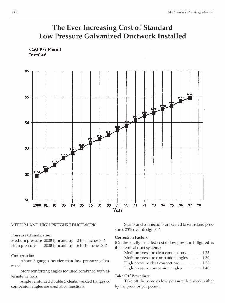
142 Mechanical Estimating Manual
MEDIUM AND HIGH PRESSURE DUCTWORK
Pressure Classifi cationMedium pressure 2000 fpm and up 2 to 6 inches S.P.High pressure 2000 fpm and up 6 to 10 inches S.P.
Construction About 2 gauges heavier than low pressure galva-nized More reinforcing angles required combined with al-ternate tie rods. Angle reinforced double S cleats, welded fl anges or companion angles are used at connections.
The Ever Increasing Cost of StandardLow Pressure Galvanized Ductwork Installed
Seams and connections are sealed to withstand pres-sures 25% over design S.P.
Correction Factors(On the totally installed cost of low pressure if fi gured as the identical duct system.) Medium pressure cleat connections ................1.25 Medium pressure companion angles ..............1.30 High pressure cleat connections .......................1.35 High pressure companion angles .....................1.40
Take Off Procedure Take off the same as low pressure ductwork, either by the piece or per pound.
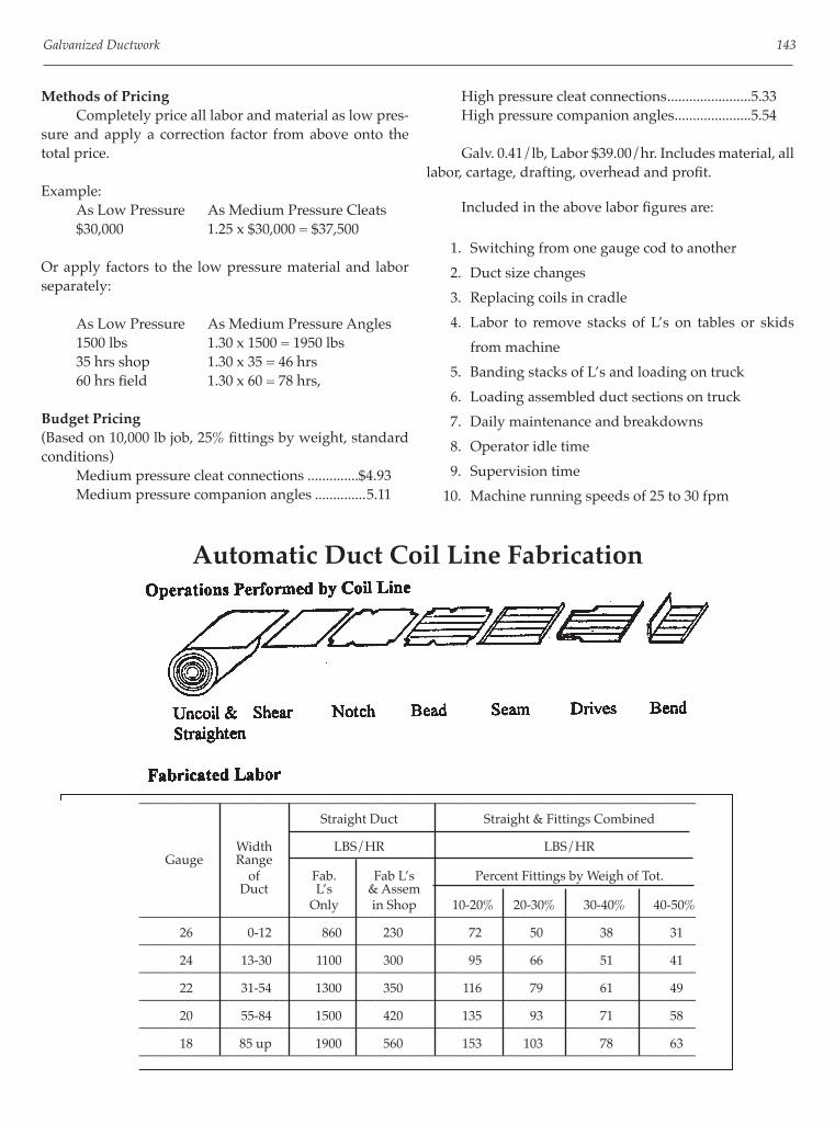
Galvanized Ductwork 143
Methods of Pricing Completely price all labor and material as low pres-sure and apply a correction factor from above onto the total price.
Example: As Low Pressure As Medium Pressure Cleats $30,000 1.25 x $30,000 = $37,500
Or apply factors to the low pressure material and labor separately:
As Low Pressure As Medium Pressure Angles 1500 lbs 1.30 x 1500 = 1950 lbs 35 hrs shop 1.30 x 35 = 46 hrs 60 hrs fi eld 1.30 x 60 = 78 hrs,
Budget Pricing(Based on 10,000 lb job, 25% fi ttings by weight, standard conditions) Medium pressure cleat connections ..............$4.93 Medium pressure companion angles ..............5.11
High pressure cleat connections .......................5.33 High pressure companion angles .....................5.54
Galv. 0.41/lb, Labor $39.00/hr. Includes material, all labor, cartage, drafting, overhead and profi t.
Included in the above labor fi gures are:
1. Switching from one gauge cod to another
2. Duct size changes
3. Replacing coils in cradle
4. Labor to remove stacks of L’s on tables or skids
from machine
5. Banding stacks of L’s and loading on truck
6. Loading assembled duct sections on truck
7. Daily maintenance and breakdowns
8. Operator idle time
9. Supervision time
10. Machine running speeds of 25 to 30 fpm
Automatic Duct Coil Line Fabrication
————————————————————————————————————————— Straight Duct Straight & Fittings Combined Width LBS/HR LBS/HR Gauge Range of Fab. Fab L’s Percent Fittings by Weigh of Tot. Duct L’s & Assem Only in Shop 10-20% 20-30% 30-40% 40-50%
————————————————————————————————————————— 26 0-12 860 230 72 50 38 31
————————————————————————————————————————— 24 13-30 1100 300 95 66 51 41
————————————————————————————————————————— 22 31-54 1300 350 116 79 61 49
————————————————————————————————————————— 20 55-84 1500 420 135 93 71 58
————————————————————————————————————————— 18 85 up 1900 560 153 103 78 63
—————————————————————————————————————————

144 Mechanical Estimating Manual
Correction Factors 1. Assemble L’s in fi eld versus in the shop ......... 1.07
Waste Allowance There is little or no waste in fabrication straight duct on a coil line. However, a 10% allowance must be added to the raw duct weight for corner seams, cleat edges and hangers.
Budget Figures Typical, commercial type ductwork, average mix of gauges and sizes, installed.
$3.96/lb 11 lbs/hr 9000 lbs/day 2-12 Mills lbs/yr

145
Chapter 11
Spiral and Light GaugeRound Duckwork
TYPES OF ROUND HVAC DUCTWORK
Spiral Pipe and Welded Fittings Spiral pipe and welded fi ttings are primarily used for medium pressure HVAC systems but they are also used to some degree in general and industrial exhaust systems. Connections are generally the slip type but compan-ion angles can also be used. Slip connections are cemented or taped in high pressure or industrial exhaust systems. Heat shrink bands may also be used. Spiral comes in round and oval confi gurations and can be either single or double skin.
Flexible Tubing Flexible tubing for HVAC systems is constructed of helical wire or bands covered with different types of fabrics depending on usage. Special fabrics may be fi re, moisture or corrosion resistant. Flexible tubing may be single skin or factory
wrapped with insulation. Connections are the slip type and are fastened with draw bands.
Residential Furnace Pipe and Fittings Residential furnace pipe is used for residential, apartment and light commercial HVAC work. It can also be used as a smoke fl ue. Pipe is constructed with length wise snaplock seams and elbows are generally the adjustable type. Residential furnace pipe is generally constructed of galvanized material but it is also available in stainless steel, aluminum and in a blue or walnut fi nish. Connections are crimped on one end, slipped to-gether and screwed or taped.
Flues Flues are used for venting fumes from smaller HVAC heating equipment. It comes in either single or double skin and in round or oval.

146 Mechanical Estimating Manual
Round Duct Gauge Data
RECOMMENDED GAUGES FOR GALVANIZED ROUND DUCTS————————————————————————————————————
DUCT LOW MEDIUM AND HIGH PRESSURE DUCTS DIAMETER, PRESSURE —————————————————————— INCHES DUCTS AND SPIRAL LONGITUDINAL WELDED FITTINGS PIPE SEAM DUCT FITTINGS
———————————————————————————————————— Up thru 8” 26 Ga. 26 Ga. 24 Ga. 22 Ga. 9-13 26 24 22 20 14-22 24 24 22 20 23-36 22 22 20 20 37-50 20 20 20 18 51-60 18 18 18 18 61-84 16 —- 16 16
————————————————————————————————————
RECOMMENDED GAUGES FOR OVAL GALVANIZED OR B.I. DUCT————————————————————————————————————
DIMENSION OF LONGITUDINAL WELDED MAJOR AXIS, SPIRAL SEAM SUCT FITTINGS INCHES
———————————————————————————————————— Up thru 24” 24 Ga. 20 Ga. 20 Ga. 25 to 36 22 20 20 37 to 48 22 18 18 49 to 50 20 18 18 51 to 70 20 16 16 71 and Over 18 16 16
————————————————————————————————————
Labor to Install Furnace Pipe,Flexible Tubing and Flues
HOURS PER PIECE, PIPE AND FITTINGS MIXED——————————————————————————
AVG FURN. FLEX. FLUE DIA. SF/LF PIPE TUBING DOUB. 5 ft 5-6 ft WALL
—————————————————————————— 4” 1.1 .4 .3 .7 6 1.6 .5 .4 .8 8 2.1 .6 .5 1.0 10 2.6 .8 .6 1.2 12 3.2 .9 .7 1.4 16 4.2 1.1 .9 — 15 4.7 1.2 1.0 — 22 5.8 1.5 1.2 — 24 6.3 — — — 30 7.9 — — — 36 9.4 — — — 42 11.0 — — — 48 12.5 — — —
—————————————————————————— (Labor based on ratio of 1 joint of pipe to 1 fi tting)

Spiral and Light Gauge Round Ductwork 147
Spiral Pipe and Fittings Correction Factors
Fabrication
Labor Correction Factors Applied to Manually Fabricated Spiral Fittings Layout from templates ....................................................................................................................... .70 Wire feed weld .................................................................................................................................... .90 Stock cut, production run ................................................................................................................. . 80 Plasma cutter ...................................................................................................................................... . 45
Budget Figures to Purchase Only Includes material, fabrication and overhead and profi t. 1. .Spiral, Pipe & Fittings ............................................................................................................. $.98/lb Pipe Only, 420 lb/hr (360 sq ft/hr) ........................................................................................ $.63/lb Fittings Only, 20.5 lb/hr (21.5 sq ft/hr) ................................................................................. $ 3.01/lb Double Skin Fittings ................................................................................................................. $ 3.86/lb 2. .Residential Furnace Pipe ........................................................................................................ $.98/lb
Spiral Accessories Four percent approximate, average size 18” diameter. Cement: 15 connections per gallon (105 ft of pipe/gal) at $17/gal Tape: 25 connections per roll (175 ft duct per roll) 2 inch wide, 180 ft/roll at $11/roll = 6.3¢ ft. Shrink bands: $1.98 per ft in rolls Hangers: Add 6%
Installation
Field Labor Correction Factors Applied to Medium Pressure Slip Connections Spiral low pressure ........................................................................................ 0.90 Spiral double skin .......................................................................................... 1.75 Oval .................................................................................................................. 1.5 Oval double skin ............................................................................................ 2.0 Underground .................................................................................................. 1.5 Thermal shrink bands on spiral ................................................................... 0.8

148 Mechanical Estimating Manual
Low Pressure Spiral DuctworkShop Hours
Straight Hours Per Foot; Fittings Hours Per Piece
Manual Fabrication—————————————————————————————————————————————
45 Elbw 90 Elbw Miters Cross Offset Reducer RdLat Diameter Straight Wye Tap 90T Lat 90RdT Sq/Rnd LatCross
————————————————————————————————————————————— 4” 0.007 1.29 0.67 1.42 1.51 2.25 2.38 2.55 5” 0.007 1.46 0.78 1.45 1.54 2.30 2.47 2.55 6” 0.007 1.67 0.86 1.47 1.56 2.35 2.55 2.55 7” 0.153 1.81 0.95 1.50 1.59 2.39 2.64 2.55
————————————————————————————————————————————— 8” 0.008 2.05 1.05 1.53 1.62 2.43 2.72 2.55 9” 0.009 2.24 1.12 1.56 1.75 2.47 2.81 2.72 10” 0.009 2.42 1.23 1.59 1.81 2.52 2.89 2.83 12” 0.010 2.81 1.42 1.64 1.99 2.86 3.09 3.15
————————————————————————————————————————————— 14” 0.012 3.18 1.61 1.92 2.17 3.14 3.30 3.45 16” 0.013 3.56. 1.79 2.10 2.35 3.41 3.50 3.77 18” 0.014 3.72 2.16 2.28 2.53 3.68 3.72 4.09 20” 0.016 4.75 2.38 2.46 2.71 3.95 3.91 4.39
————————————————————————————————————————————— 22” 0.018 5.80 2.69 2.59 2.97 4.22 4.17 4.75 24” 0.020 6.16 3.06 2.81 3.21 4.49 4.33 5.02 26” 0.020 7.07 3.35 2.95 3.62 5.08 4.52 5.72 28” 0.022 8.04 3.86 3.47 4.14 5.68 4.82 6.39
————————————————————————————————————————————— 30” 0.025 8.16 4.20 3.91 4.31 6.23 4.94 7.02 32” 0.026 8.41 4.45 4.35 4.80 6.94 5.13 7.64 34” 0.028 8.98 4.56 4.79 5.31 7.67 5.33 8.26 36” 0.029 9.52 4.74 5.24 5.78 8.35 5.55 8.89
————————————————————————————————————————————— 38” 0.031 9.92 5.01 5.47 6.08 8.72 5.73 9.51 40” 0.032 10.31 5.20 6.56 6.38 9.10 5.95 10.13 42” 0.034 10.88 5.29 5.96 6.68 9.48 6.16 10.75 44” 0.036 11.39 5.40 6.20 6.98 9.85 6.39 11.27
————————————————————————————————————————————— 46” 0.037 11.73 5.64 6.43 7.28 10.23 6.60 11.79 48” 0.039 12.24 5.84 6.68 7.58 10.61 6.77 12.31 50” 0.041 12.58 5.87 6.92 7.88 10.98 7.01 12.78 52” 0.043 12.75 6.16 7.16. 8.18 11.36 7.18 13.24
————————————————————————————————————————————— 54” 0.044 12.92 6.38 7.40 8.48 11.74 7.39 13.71 56” 0.046 13.09 6.52 7.64 8.78 12.11 7.56 14.18 58” 0.048 13.43 6.78 7.88 9.08 12.49 7.86 14.65 60” 0.049 13,60 6.93 8.13 9.38 12.87 8.00 15.11
—————————————————————————————————————————————

Spiral and Light Gauge Round Ductwork 149
Low Pressure Spiral DuctworkShop Hours
Straight Hours Per Foot; Fittings Hours Per Piece
Automated Fabrication—————————————————————————————————————————————
45 Elbw 90 Elbw Miters Cross Offset Reducer RdLat Diameter Straight Wye Tap 90T Lat 90RdT Sq/Rnd LatCross
————————————————————————————————————————————— 4” 0.008 0.91 0.47 1.00 1.07 1.70 1.79 1.92 5” 0.008 1.03 0.55 1.02 1.09 1.73 1.86 1.92 6” 0.008 1.18 0.61 1.04 1.10 1.77 1.92 1.92 7” 0.180 1.28 0.67 1.06 1.12 1.80 1.98 1.92
————————————————————————————————————————————— 8” 0.009 1.45 0.74 1.08 1.14 1.83 2.05 1.92 9” 0.010 1.58 0.79 1.10 1.24 1.86 2.11 2.05 10” 0.011 1.71 0.87 1.12 1.28 1.90 2.18 2.13 12” 0.012 1.98 1.00 1.16 1.40 2.16 2.33 2.37
————————————————————————————————————————————— 14” 0.014 2.24 1.13 1.36 1.53 2.36 2.48 2.60 16” 0.015 2.51 1.27 1.48 1.66 2.57 2.64 2.84 18” 0.017 2.63 1.52 1.61 1.79 2.77 2.80 3.08 20” 0.019 3.35 1.68 1.73 1.91 2.98 2.94 3.31
————————————————————————————————————————————— 22” 0.021 4.09 1.90 1.83 2.09 3.17 3.14 3.58 24” 0.023 4.35 2.16 1.99 2.27 3.38 3.26 3.78 26” 0.024 4.99 2.36 2.08 2.56 3.83 3.40 4.31 28” 0.026 5.68 2.72 2.45 2.92 4.28 3.63 4.81
————————————————————————————————————————————— 30” 0.029 5.76 2.96 2.76 3.04 4.69 3.72 5.29 32” 0.031 5.93 3.14 3.07 3.39 5.22 3.87 5.75 34” 0.033 6.34 3.22 75.00 3.75 5.77 4.01 6.22 36” 0.034 6.72 3.35 3.70 4.08 6.28 4.18 6.69
————————————————————————————————————————————— 38” 0.036 7.00 3.53 3.86 4.29 6.57 4.31 7.16 40” 0.038 7.28 3.67 4.63 4.50 6.85 4.48 7.63 42” 0.040 7.68 3.73 4.21 4.72 7.14 4.64 8.10 44” 0.042 8.04 3.81 4.37 4.93 7.42 4.81 8.49
————————————————————————————————————————————— 46” 0.044 8.28 3.98 4.54 5.14 7.70 4.97 8.88 48” 0.046 8.64 4.12 4.72 5.35 7.99 5.10 9.27 50” 0.048 8.88 4.14 4.88 5.56 8.27 5.28 9.62 52” 0.050 9.00 4.35 5.05 5.77 8.55 5.41 9.97
————————————————————————————————————————————— 54” 0.052 9.12 4.51 5.23 5.99 8.84 5.56 10.32 56” 0.054 9.24 4.60 5.39 6.20 9.12 5.69 10.68 58” 0.056 9.48 4.79 5.56 6.41 9.40 5.92 11.03 60” 0.058 9.60 4.89 5.74 62 9.69 6.02 11.38
—————————————————————————————————————————————

150 Mechanical Estimating Manual
Low Pressure Spiral DuctworkField Hours
Straight Hours Per Foot; Fittings Hours Per Piece
————————————————————————————————————————————— 90 Elbw 45 Elbw Reducer 90T Wye Miters Offset LatCross Diameter Straight Cross 90RdT Lat RdLat Sq/Rd Tap Flex Tube
————————————————————————————————————————————— 4” 0.054 0.32 0.32 0.32 0.32 0.32 0.20 0.060 5” 0.063 0.36 0.36 0.36 0.36 0.36 0.20 0.070 6” 0.072 0.41 0.41 0.41 0.41 0.41 0.20 0.080 7” 0.072 0.45 0.45 0.45 0.45 0.45 0.20 0.090
————————————————————————————————————————————— 8” 0.081 0.50 0.50 0.50 0.50 0.50 0.20 0.100 9” 0.090 0.00 0.00 0.00 0.00 0.00 0.20 0.110 10” 0.099 0.59 0.59 0.59 0.59 0.59 0.20 0.120 12” 0.117 0.59 0.59 0.68 0.68 0.68 0.20 0.140
————————————————————————————————————————————— 14” 0.126 0.76 0.76 0.58 0.58 0.58 0.27 0.160 16” 0.135 0.93 0.93 0.71 0.71 0.71 0.34 0.180 18” 0.153 1.11 1.11 0.85 0.85 0.85 0.41 0.190 20” 0.162 1.28 1.28 0.97 0.97 0.97 0.49 0.200
————————————————————————————————————————————— 22” 0.180 1.45 1.45 1.11 1.11 1.11 0.56 0.230 24” 0.198 1.62 1.62 1.23 1.23 1.23 0.62 0.260 26” 0.216 1.79 1.79 1.37 1.37 1.37 0.69 0.000 28” 0.234 1.96 1.96 1.50 1.50 1.50 0.77 0.000
————————————————————————————————————————————— 30” 0.261 2.14 2.14 1.63 1.63 1.63 0.84 0.000 32” 0.261 2.31 2.31 1.76 1.76 1.76 0.91 0.000 34” 0.288 2.48 2.48 1.90 1.90 1.90 0.98 0.000 36” 0.306 2.66 2.66 2.03 2.03 2.03 1.04 0.000
————————————————————————————————————————————— 38” 0.324 2.83 2.83 2.15 2.15 2.15 1.12 0.000 40” 0.333 3.00 3.00 2.28 2.28 2.28 1.19 0.000 42” 0.342 3.18 3.18 2.41 2.41 2.41 1.25 0.000 44” 0.351 3.35 3.35 2.55 2.55 2.55 1.32 0.000
————————————————————————————————————————————— 46” 0.369 3.52 3.52 2.68 2.68 2.68 1.40 0.000 48” 0.378 3.69 3.69 2.81 2.81 2.81 1.47 0.000 50” 0.396 3.86 3.86 2.93 2.93 2.93 1.54 0.000 52” 0.414 4.03 4.03 3.06 3.06 3.06 1.61 0.000
————————————————————————————————————————————— 54” 0.423 4.21 4.21 3.20 3.20 3.20 1.67 0.000 56” 0.432 4.38 4.38 3.34 3.34 3.34 1.75 0.000 58” 0.441 4.55 4.55 3.47 3.47 3.47 1.82 0.000 60” 0.450 4.73 4.73 3.60 3.60 3.60 1.89 0.000
—————————————————————————————————————————————

Spiral and Light Gauge Round Ductwork 151
Medium Pressure Spiral DuctworkShop Hours
Straight Hours Per Foot; Fittings Hours Per Piece
Manual Fabrication—————————————————————————————————————————————
45 Elbw 90 Elbw Miters Cross Offset Reducer RdLat Diameter Straight Wye Tap 90T Lat 90RdT Sq/Rnd LatCross
————————————————————————————————————————————— 4” 0.008 1.52 0.79 1.67 1.78 2.65 1.80 3.00 5” 0.008 1.72 0.92 1.70 1.81 2.70 2.90 3.00 6” 0.008 1.96 1.01 1.73 1.84 2.76 3.00 3.00 7” 0.080 2.13 1.12 1.77 1.87 2.80 3.10 3.00
————————————————————————————————————————————— 8” 0.009 2.41 1.23 1.80 1.90 2.86 3.20 3.00 9” 0.010 2.63 1.32 1.84 2.06 2.91 3.30 3.20 10” 0.011 2.85 1.45 1.87 2.13 2.97 3.40 3.33 12” 0.012 3.30 1.67 1.93 2.34 3.37 3.64 3.70
————————————————————————————————————————————— 14” 0.014 3.74 1.89 2.26 2.55 3.69 3.88 4.06 16” 0.015 4.19 2.11 2.47 2.76 4.01 4.12 4.43 18” 0.017 4.38 2.54 2.68 2.98 4.33 4.38 4.81 20” 0.019 5.59 2.80 2.89 3.19 4.65 4.60 5.17
————————————————————————————————————————————— 22” 0.021 6.82 3.16 3.05 3.49 4.96 4.91 5.59 24” 0.023 7.25 3.60 3.31 3.78 5.28 5.09 5.91 26” 0.024 8.32 3.94 3.47 4.26 5.98 5.32 6.73 28” 0.026 9.46 4.54 4.08 4.87 6.68 5.67 7.52
————————————————————————————————————————————— 30” 0.029 9.60 4.94 4.60 5.07 7.33 5.81 8.26 32” 0.031 9.89 5.24 5.12 5.65 8.16 6.04 8.99 34” 0.033 10.56 5.36 5.64 6.25 9.02 6.27 9.72 36” 0.034 11.20 5.58 6.16 6.80 9.82 6.53 10.46
————————————————————————————————————————————— 38” 0.036 11.67 5.89 6.44 7.15 10.26 6.74 11.19 40” 0.038 12.13 6.12 7.72 7.50 10.70 7.00 11.92 42” 0.040 12.80 6.22 7.01 7.86 11.15 7.25 12.65 44” 0.042 13.40 6.35 7.29 8.21 11.59 7.52 13.26
————————————————————————————————————————————— 46” 0.044 13.80 6.64 7.57 8.56 12.03 7.76 13.87 48” 0.046 14.40 6.87 7.86 8.92 12.48 7.97 14.48 50” 0.048 14.80 6.90 8.14 9.27 12.92 8.25 15.03 52” 0.050 15.00 7.25 8.42 9.62 13.36 8.45 15.58
————————————————————————————————————————————— 54” 0.052 15.20 7.51 8.71 9.98 13.81 8.69 16.13 56” 0.054 15.40 7.67 8.99 10.33 14.25 8.89 16.68 58” 0.056 15.80 7.98 9.27 10.68 14.69 9.25 17.23 60” 0.058 16.00 8.15 9.56 11.04 15.14 9.41 17.78
—————————————————————————————————————————————

152 Mechanical Estimating Manual
Medium Pressure Spiral DuctworkShop Hours
Straight Hours Per Foot; Fittings Hours Per Piece
Automated Fabrication—————————————————————————————————————————————
45 Elbw 90 Elbw Miters Cross Offset Reducer RdLat Diameter Straight Wye Tap 90T Lat 90RdT Sq/Rnd LatCross
————————————————————————————————————————————— 4” 0.008 1.14 0.59 1.25 1.34 1.99 2.10 2.25 5” 0.008 1.29 0.69 1.28 1.36 2.03 2.18 2.25 6” 0.008 1.47 0.76 1.30 1.38 2.07 2.25 2.25 7” 0.180 1.60 0.84 1.33 1.40 2.11 2.33 2.25
————————————————————————————————————————————— 8” 0.009 1.81 0.92 1.35 1.43 2.15 2.40 2.25 9” 0.010 1.97 0.99 1.38 1.55 2.18 2.48 2.40 10” 0.011 2.14 1.09 1.40 1.60 2.23 2.55 2.50 12” 0.012 2.48 1.25 1.45 1.76 2.53 2.73 2.78
————————————————————————————————————————————— 14” 0.014 2.81 1.42 1.70 1.91 2.77 2.91 3.05 16” 0.015 3.14 1.58 1.85 2.07 3.01 3.09 3.32 18” 0.017 3.29 1.91 2.01 2.24 3.25 3.29 3.61 20” 0.019 4.19 2.10 2.17 2.39 3.49 3.45 3.88
————————————————————————————————————————————— 22” 0.021 5.12 2.37 2.29 2.62 3.72 3.68 4.19 24” 0.023 5.44 2.70 2.48 2.84 3.96 3.82 4.43 26” 0.024 6.24 2.96 2.60 3.20 4.49 3.99 5.05 28” 0.026 7.10 3.41 3.06 3.65 5.01 4.25 5.64
————————————————————————————————————————————— 30” 0.029 7.20 3.71 3.45 3.80 5.50 4.36 6.20 32” 0.031 7.42 3.93 3.84 4.24 6.12 4.53 6.74 34” 0.033 7.92 4.02 4.23 4.69 6.77 4.70 7.29 36” 0.034 8.40 4.19 4.62 5.10 7.37 4.90 7.85
————————————————————————————————————————————— 38” 0.036 8.75 4.42 4.83 5.36 7.70 5.06 8.39 40” 0.038 9.10 4.59 5.79 5.63 8.03 5.25 8.94 42” 0.040 9.60 4.67 5.26 5.90 8.36 5.44 9.49 44” 0.042 10.05 4.76 5.47 6.16 8.69 5.64 9.95
————————————————————————————————————————————— 46” 0.044 10.35 4.98 5.68 6.42 9.02 5.82 10.40 48” 0.046 10.80 5.15 5.90 6.69 9.36 5.98 10.86 50” 0.048 11.10 5.18 6.11 6.95 9.69 6.19 11.27 52” 0.050 11.25 5.44 6.32 7.22 10.02 6.34 11.69
————————————————————————————————————————————— 54” 0.052 11.40 5.63 6.53 7.49 10.36 6.52 12.10 56” 0.054 11.55 5.75 6.74 7.75 10.69 6.67 12.51 58” 0.056 11.85 5.99 6.95 8.01 11.02 6.94 12.92 60” 0.058 12.00 6.11 7.17 8.28 11.36 7.06 13.34
—————————————————————————————————————————————

Spiral and Light Gauge Round Ductwork 153
Medium Pressure Spiral DuctworkField Hours
Straight Hours Per Foot; Fittings Hours Per Piece
————————————————————————————————————————————— 90 Elbw 45 Elbw Reducer 90T Wye Miters Offset LatCross Diameter Straight Cross 90RdT Lat RdLat Sq/Rd Tap Flex Tube
————————————————————————————————————————————— 4” 0.060 0.35 0.35 0.35 0.35 0.35 0.22 0.060 5” 0.070 0.40 0.40 0.40 0.40 0.40 0.22 0.070 6” 0.080 0.45 0.45 0.45 0.45 0.45 0.22 0.080 7” 0.080 0.50 0.50 0.50 0.50 0.50 0.22 0.090
————————————————————————————————————————————— 8” 0.090 0.55 0.55 0.55 0.55 0.55 0.22 0.100 9” 0.100 0.00 0.00 0.00 0.00 0.00 0.22 0.110 10” 0.110 0.65 0.65 0.65 0.65 0.65 0.22 0.120 12” 0.130 0.65 0.65 0.75 0.75 0.75 0.22 0.140
————————————————————————————————————————————— 14” 0.140 0.84 0.84 0.64 0.64 0.64 0.30 0.160, 16” 0.150 1.03 1.03 0.79 0.79 0.79 0.38 0.180 18” 0.170 1.23 1.23 0.94 0.94 0.94 0.46 0.190 20” 0.180 1.42 1.42 1.08 1.08 1.08 0.54 0.200
————————————————————————————————————————————— 22” 0.200 1.61 1.61 1.23 1.23 1.23 0.62 0.230 24” 0.220 1.80 1.80 1.37 1.37 1.37 0.69 0.260 26” 0.240 1.99 1.99 1.52 1.52 1.52 0.77 0.000 28” 0.260 2.18 2.18 1.67 1.67 1.67 0.85 0.000
————————————————————————————————————————————— 30” 0.290 2.38 2.38 1.81 1.81 1.81 0.93 0.000 32” 0.290 2.57 2.57 1.96 1.96 1.96 1.01 0.000 34” 0.320 2.76 2.76 2.11 2.11 2.11 1.09 0.000 36” 0.340 2.95 2.95 2.25 2.25 2.25 1.16 0.000
————————————————————————————————————————————— 38” 0.360 3.14 3.14 2.39 2.39 2.39 1.24 0.000 40” 0.370 3.33 3.33 2.53 2.53 2.53 1.32 0.000 42” 0.380 3.53 3.53 2.68 2.68 2.68 1.39 0.000 44” 0.390 3.72 3.72 2.83 2.83 2.83 1.47 0.000
————————————————————————————————————————————— 46” 0.410 3.91 3.91 2.98 2.98 2.98 1.55 0.000 48” 0.420 4.10 4.10 3.12 3.12 3.12 1.63 0.000 50” 0.440 4.29 4.29 3.25 3.25 3.25 1.71 0.000 52” 0.460 4.48 4.48 3.40 3.40 3.40 1.79 0.000
————————————————————————————————————————————— 54” 0.470 4.68 4.68 3.56 3.56 3.56 1.86 0.000 56” 0.480 4.87 4.87 3.71 3.71 3.71 1.94 0.000 58” 0.490 5.06 5.06 3.86 3.86 3.86 2.02 0.000 60” 0.500 5.26 5.26 4.00 4.00 4.00 2.10 0.000
—————————————————————————————————————————————

This page intentionally left blank

155
Chapter 12
Estimating Fiberglass Ductwork
INTRODUCTION
Fiberglass ductwork has the following advantages over sheet metal:
• It costs less than conventionally fabricated steel ductwork: 5% less than bare galvanized 30% less than insulated sheet metal 3 5% less than lined sheet metal
• It costs less than galvanized ductwork fabricated on a coil line if insulated or lined: 20% less than insulated 35% less than fi ned
• However, fi berglass costs 15% more than bare galvanized off of a coil line.
• It requires very little machinery and tools to fabricate, minimal fl oor space and consequently overhead costs are far less than a sheet metal shop.
• It’s more fl exible than sheet metal, easier to revise and manipulate at the job site in order to fi t into diverse, unpredictable fi eld conditions and to meet precise outlet locations.
• It can be fabricated either in the shop or at the job site.
• It’s lightweight. Shipping, material handling and hoisting are far easier than with sheet metal.
• It has built in thermal insulation and acoustical absorption.
• It has built in built in a vapor barrier.
• And lastly, it’s an automatic energy saver over bare steel because it’s self insulating and virtually leak proof.
Takeoff Procedures1. Use duct take off sheet and fi ll out heading.
2. List inside dimensions of duct.
3. Write down type of duct. Use abbreviation.
4. Measure off pipe in 4 foot lengths and list each length.
5. Put down equivalent lengths for each fi tting.
6. List sheet metal components separately on bottom of duct take off sheet or on separate sheet, as you go along.
Material Extension1. Total the linear footage on each line and enter total
in total linear foot column.
2. Enter the sq ft/lin ft from the chart which includes the allowance for the 8” comer overlap and a 5% waste factor.
3. Multiply the length times the sq/lin ft and enter in the square feet column.
4. Add up the total square feet.
Material CostsTypical current prices: Square Feet Ordered Over 10,000Type Board 0-2400 2400-10,000 Truckload 475 $0.96 $0.87 $0.79 800 $1.06 $0.10 $0.96 1400 $1.32 $1.28 $1.15
Budget Figures The budget cost of a 1000 square foot or larger batch of typical fi berglass duct work, under standard conditions, including a markup of 30% for overhead and profi t, based on union wages, is about $4.41 per square foot of duct. Non union cost is about 33% less, roughly $3.04 per square foot.

156 Mechanical Estimating Manual
Calculating Labor
Following labor productivity rates are based on:
1. Volume of 1000 SF and up2. 800 Board3. Average duct size of 18” x 12”, or equivalent 24
gauge galv.4. Tie rod reinforcing.5. Rates based on gross square footage including 8”
overlap and 5% waste.6. Using standard grooving machine.
(See Fabrication Labor at the top of the following page.)
Installation Labor Neither the duct size nor the percentage of fi ttings affects the installation productivity rate appreciably. Consequently the erection rate remains relatively constant at 30 sf/hr.
Correction Factors1. Shop labor
a. Hand grooving machine versus grooving machine .............................................. 1.50b. Auto grooving machine versus manual machine ...................................... .90c. Auto closer versus manual ................................. .70d. Auto groover and closer ..................................... .60e. Exhaust and return ducts with tie rods in conduits ............................................ 1.33f. Fittings versus straight duct ............................. 1.50g. “V” groove versus shiplap ............................... 1.05
2. Channel or “T” bar reinforcing versus tie rods Shop ..................................................................... 1.20 Field ..................................................................... 1.10
3. 475 Board versus 800, Material costs ........................ .90 Shop and Field labor ............................. .95
4. 1400 Board versus 800, Material costs .................... 1.20 Shop and Field labor ........................... 1.05
5. Material quantity discounts 0-2400 SF ................... 1.05 2400-20,000 SF ...................................... 1.00 Factory, truck load .......................................... .94 Factory, car load .............................................. .90
Square Foot Per Linear Footof Fiberglass Ductwork
————————————————————————— Semi-Perim SF/LF SF/LFI.D. Includes allowances, No Width plus 8” corner overlap Allowance Depth 5% waste Included————————————————————————— 12 2.8 2.00 14 3.1 2.34 16 3.5 2.67 18 3.9 3.00 20 4.2 3.34————————————————————————— 22 4.6 3.67 24 4.9 4.00 26 5.2 4.34 28 5.6 4.67 30 5.9 5.00————————————————————————— 32 6.5 5.34 34 6.7 5.67 36 7.0 6.00 38 7.3 6.34 40 7.7 6.67————————————————————————— 42 8.0 7.00 44 8.4 7.34 46 8.8 7.67 48 9.1 8.00 50 9.5 8.34————————————————————————— 52 9.8 8.67 54 10.1 9.00 56 10.5 9.34 58 10.9 9.67 60 11.2 10.00————————————————————————— 62 11.6 10.34 64 11.9 10.67 66 12.3 11.00 68 12.6 11.34 70 12.9 11.67————————————————————————— 72 13.3 12.00 74 13.7 12.34 76 14.0 12.67 78 14.4 13.00 80 14.7 13.34————————————————————————— 82 15.1 13.67 84 15.4 14.00 86 15.8 14.34 88 16.1 14.67 90 16,5 15.00————————————————————————— 92 16.8 15.34 94 17.2 15.67 96 17.5 16.00 98 17.9 16.34 100 18.2 16.67—————————————————————————

Estimating Fiberglass Ductwork 157
FABRICATION LABOR———————————————————————————————————————
Size Ranges———————————————————————————————————————
Percentage 0.12” 13.30” 31.54” 55.84” 85.96”
Fittings SF/ HR/ SF/ HR/ SF/ HR/ SF/ HR/ SF/ HR/ HR SF HR SF HR SF HR SF HR SF
——————————————————————————————————————— Str. Duct. Only 59 .0169 62 .0161 56 .0179 53 .0189 38 .0263 10-20% 55 .0183 58 .0174 52 .0191 49 .0202 35 .0284 20-30% 52 .0191 55 .0182 50 .0200 47 .0211 34 .0297 30-40% 50 .0200 53 .0190 48 .0208 45 .0220 32 .0311 Fittings Only 39 .0256 41 .0244 38 .0263 36 .0278 25 .0400
———————————————————————————————————————
Example of Fiberglass DuctworkTakeoff and Extension

158 M
echanical E
stimatin
g Man
ual
Pricing Sheet Metal ComponentsFiberglass Ductboard
Estimate Summary and Extension Sheet
————————————————————————— DIRECT
ITEM SIZE MATERIAL & LABOR—————————————————————————Turning Vanes 12x6 $24.24 18x12 50.10 24x12 58.18 36x12 82.42 42x12 111.52 48x24 153.54 60x24 205.25—————————————————————————Splitter Dampers 9x9 $30.71 18x12 35.55 30x12 43.63 42x18 54.95—————————————————————————Round Diffuser Collar 8” dia $54.95 12 71.11 18 82.42—————————————————————————Rectangular Diffuser 12x12 $69.50Collar 24x12 82.42 48x24 187.47—————————————————————————Fire Damper Sleeves 24x12 $143.84 18 Gauge 36x18 190.71 48x12 260.20—————————————————————————Electric Coil Sleeves 12x12 $74.34 24x12 108.28 36x12 143.84 48x12 205.25—————————————————————————Acces Doors 12x12 $72.73 24x12 87.28—————————————————————————Reinforcing Channels —Material $0.20LFand formed “T” Bars Labor-Fab & Install 24” long .10 Hrs ea 36” .14 48” .18 60” .22 72” .26—————————————————————————

159
Chapter 13
Heavy Gauge Ductwork
TYPES OF INDUSTRIAL EXHAUST DUCTWORK
There are four basic categories of materials used for ductwork in air pollution control and, industrial and commercial exhaust systems.
1. Galvanized ductwork, either round or rectangular, is used in many applications for heat, moisture and dust removal when corrosion and abrasion do not present problems.
2. Black iron ductwork, hot or cold rolled, round or rectangular is used in many applications for heat, moisture and dust removal when corrosion and abrasion do not present problems.
3. Corrosion and moisture resistant ductwork round
Budget EstimatingRectangular Black Iron Ductwork
Metal FlangesPer Pound and Per Square Foot
————————————————————————————————————Average Lb/Hr, Sf/Hr Labor Productivity Rates and Budget Prices
Gauge Fabrication Installation Budget Price W/O & P Lb/Hr Sf/Hr Lb/Hr Sf/Hr Per/Lb Per/Sf
———————————————————————————————————— 18 28 14 34 17.0 $4.73 $ 9.44 16 31 12.5 39 15.5 4.32 10.60 14 35 11 45 14.2 3.57 11.52 12 44 10 50 11.5 3.43 15.13 10 52 9 55 10.0 3.05 16.73 3/16” 53 7.0 41 5.4 3.30 25.45
————————————————————————————————————
Based on $0.40 per pound for hot rolled steel and $39.00 for labor. Labor productivity based on average 6 foot perimeter (24x12 plus or minus) and 25 percent fi ttings by weight or square footage.
or rectangular, is fabricated from the following materials:
PVC Stainless Steel FRP PVC Coated Galvanized Aluminum Transite
4. High temperature ductwork is generally stainless steel.
Round ductwork is used more commonly than rectangular in air pollution control and material conveying work. Connections may be cleated, slip, sheet metal fl anged or companion angle fl anged and bolted, welded, soldered, cemented, gasketed, sleeved, coupled, or riveted.

160 Mechanical Estimating Manual
Heavy Gauge Ductwork Labor FactorsShowing Relationship Between Different
Materials, Gauges and Connections
TYPE OF MATERIAL LABOR FACTOR————————————————————————————————
Multipliers SHOP FIELD Black Iron, (Base) 1.00 1.00 Stainless Steel 1.25 1.25 Galvanized 1.10 1.06 Aluminum .75 .75 PVC 1/4”, 3/16” .43 .82 FRP 1/4”, 3/16” .83 .87 Aluminized Steel 1.00 1.00 Cor-Ten 1.00 1.00

Heavy Gauge Ductwork 161
ANGLE FLANGE CONNECTION, BLACK IRONGauge Factors
———————————————————————————————— Multipliers GAUGE SHOP FIELD 20 .75 .75 18 .80 .80 16 .90 .90 14 (Base) 1.00 1.00 12 1.10 1.25 10 1.20 1.45 8 1.40 2.00 3/16” 1.60 2.60 1/4”) 2.13 3.40 3/8” 2.63 3.90 1/2” 3.13 4.40
BENT METAL FLANGE CONNECTION(As Compared to Angle Flange Connection)
———————————————————————————————— Shop Factor .90 Multipliers Field Factor .95
WELDED CONNECTION(As Compared to Angle Flange Connection)
———————————————————————————————— Shop Factor .60 Multipliers Field Factor 1.50
Examples: Given 10 gauge black iron duct with angle fl anges shop… 200/0 more labor, fi eld 45% more.Given same gauge duct with welded connections shop 40% less labor, fi eld 50% more.
Rectangular Black Iron DuctworkWith Companion Angles
Per Piece Labor and Material
Uses: Boiler breechings, oven exhausts, material conveying, kitchens
Correction Factors (On 14 gauge per piece labor) Shop Field 1. 18 gauge .80 .80 2. 16 gauge .90 .90 3. 12 gauge 1.10 1.25 4. 10 gauge 1.20 1.45 5. 3/16ths inch plate 1.60 2.60 6. 5 foot long joints 1.10 1.10 7. 8 foot long joints 1.50 1.50
Budget price, typical 14 gauge 24x12 duct section. $3.49 per lb.

162 Mechanical Estimating Manual
Rectangular Heavy Gauge Ductwork14 Gauge Black Iron, Angle Flange Connection
Shop HoursFittings Hours Per Piece; Straight Hours Per Foot
Manual Fabrication————————————————————————————————————————————
Sq/Elbw Size Straight 90 Elbw 45 Elbw Trans Tap Wye Sq/Rd Offset Door
———————————————————————————————————————————— 12x12 2.24 3.45 2.58 2.58 2.04 3.04 6.49 3.87 2.73 18x12 2.58 4.13 3.10 3.00 2.40 3.59 7.20 4.50 2.86 24x12 2.92 4.81 3.61 3.42 2.76 4.14 7.90 5.13 2.99 30x12 3.25 5.49 4.12 3.84 3.12 4.69 8.61 5.76 3.11
———————————————————————————————————————————— 36x12 3.59 6.17 4.63 4.26 3.48 5.24 9.38 6.39 3.24 36x18 3.92 6.85 5.14 4.68 3.84 5.80 10.28 7.02 3.36 42x18 4.26 8.64 6.48 5.10 4.20 6.35 11.18 7.65 3.49 48x18 4.60 9.43 7.08 5.52 4.56 6.90 12.08 8.28 3.61
———————————————————————————————————————————— 54x18 4.93 10.22 7.67 5.94 4.92 7.45 12.97 8.91 3.74 60x15 5.27 11.02 8.27 6.36 5.28 8.00 13.87 9.54 3.86 72x18 5.94 16.49 12.37 7.20 6.00 9.11 15.67 10.80 4.11 84x18 6.61 18.59 13.95 8.04 6.72 10.21 17.46 12.06 4.36
————————————————————————————————————————————
Automated Fabrication————————————————————————————————————————————
Sq/Elbw Size Straight 90 Elbw 45 Elbw Trans Tap Wye Sq/Rd Offset Door
———————————————————————————————————————————— 12x12 1.68 2.59 1.94 1.94 1.53 2.28 4.87 2.90 2.05 18x12 1.94 3.10 2.33 2.25 1.80 2.69 5.40 3.38 2.15 24x12 2.19 3.61 2.71 2.57 2.07 3.11 5.93 3.85 2.24 30x12 2.44 4.12 3.09 2.88 2.34 3.52 6.46 4.32 2.33
———————————————————————————————————————————— 36x12 2.69 4.63 3.47 3.20 2.61 3.93 7.04 4.79 2.43 36x18 2.94 5.14 3.86 3.51 2.88 4.35 7.71 5.27 2.52 42x18 3.20 6.48 4.86 3.83 3.15 4.76 8.39 5.74 2.62 48x18 3.45 7.07 5.31 4.14 3.42 5.18 9.06 6.21 2.71
———————————————————————————————————————————— 54x18 3.70 7.67 5.75 4.46 3.69 5.59 9.73 6.68 2.81 60x18 3.95 8.27 6.20 4.77 3.96 6.00 10.40 7.16 2.90 72x18 4.46 12.37 9.28 5.40 4.50 6.83 11.75 8.10 3.08 84x18 4.96 13.94 10.46 6.03 5.04 7.66 13.10 9.05 3.27
————————————————————————————————————————————

Heavy Gauge Ductwork 163
Rectangular Heavy Gauge Ductwork14 Gauge Black Iron, Angle Flange Connection
Field HoursFittings Hours Per Piece; Straight Hours Per Foot
———————————————————————————————— 45 Elbw Sq/Elbw 90 Elbw Trans Size Straight Wye Offset Tap Sq/Rd
———————————————————————————————— 12x12 1.60 1.44 1.60 0.39 1.16
18x12 1.90 1.71 1.90 0.46 1.35
24x12 2.20 1.98 2.20 0.53 1.55
30x12 2.50 2.25 2.50 0.60 1.74————————————————————————————————
36x12 2.80 2.52 2.80 0.68 1.93
36x18 3.10 2.79 3.10 0.75 2.12
42x18 3.40 3.06 3.40 0.82 2.31
46x18 3.70 3.33 3.70 0.89 2.50————————————————————————————————
54x18 4.00 3.60 4.00 0.96 2.69
60x18 4.30 3.87 4.30 1.04 2.88
72x18 4.90 4.41 4.90 1.18 3.26
84x18 5.50 4.95 5.50 1.32 3.65————————————————————————————————

164 Mechanical Estimating Manual
Rectangular Heavy Gauge Ductwork14 Gauge Galvanized, Angle Flange Connection
Shop Hours 4Fittings Hours Per Piece; Straight Hours 4 Foot
Manual Fabrication————————————————————————————————————————————
Sq/Elbw Size Straight 90 Elbw 45 Elbw Trans Tap Wye Sq/Rd Offset Door
———————————————————————————————————————————— 12x12 2.46 3.80 2.84 2.84 2.24 3.34 7.14 4.26 3.00 18x12 2.84 4.54 3.41 3.30 2.64 3.95 7.92 4.95 3.15 24x12 3.21 5.29 3.97 3.76 3.04 4.55 8.69 5.64 3.29 30x12 3.58 6.04 4.53 4.22 3.43 5.16 9.47 6.34 3.42 36x12 3.95 6.79 5.09 4.69 3.83 5.76 10.32 7.03 3.56 36x18 4.31 7.54 5.65 5.15 4.22 6.38 11.31 7.72 3.70 42x18 4.69 9.50 7.13 5.61 4.62 6.99 12.30 8.42 3.84 48x18 5.06 10.37 7.79 6.07 5.02 7.59 13.29 9.11 3.97 54x18 5.42 11.24 8.44 6.53 5.41 8.20 14.27 9.80 4.11 60x18 5.80 12.12 9.10 7.00 5.81 8.80 15.26 10.49 4.25 72x18 6.53 18.14 13.61 7.92 6.60 10.02 17.24 11.88 4.52 84x18 7.27 20.45 15.35 8.84 7.39 11.23 19.21 13.27 4.80
————————————————————————————————————————————
Automated Fabrication————————————————————————————————————————————
Sq/Elbw Size Straight 90 Elbw 45 Elbw Trans Tap Wye Sq/Rd Offset Door
———————————————————————————————————————————— 12x12 1.85 2.85 2.13 2.13 1.68 2.51 5.35 3.19 2.25 18x12 2.13 3.41 2.56 2.48 1.98 2.96 5.94 3.71 2.36 24x12 2.41 3.97 2.98 2.82 2.28 3.42 6.52 4.23 2.47 30x12 2.68 4.53 3.40 3.17 2.57 3.87 7.10 4.75 2.57 36x12 2.96 5.09 3.82 3.51 2.87 4.32 7.74 5.27 2.67 36x18 3.23 5.65 4.24 3.86 3.17 4.79 8.48 5.79 2.77 42x18 3.51 7.13 5.35 4.21 3.47 5.24 9.22 6.31 2.88 48x18 3.80 7.78 5.84 4.55 3.76 5.69 9.97 6.83 2.98 54x18 4.07 8.43 6.33 4.90 4.06 6.15 10.70 7.35 3.09 60x18 4.35 9.09 6.82 5.25 4.36 6.60 11.44 7.87 3.18 72x18 4.90 13.60 10.21 5.94 4.95 7.52 12.93 8.91 3.39 84x18 5.45 15.34 11.51 6.63 5.54 8.42 14.40 9.95 3.60
————————————————————————————————————————————

Heavy Gauge Ductwork 165
Rectangular Heavy Gauge Ductwork14 Gauge Galvanized, Angle Flange Connection
Field HoursFittings Hours Per Piece; Straight Hours Per Foot
———————————————————————————————— 45 Elbw Sq/Elbw 90 Elbw Trans Size Straight Wye Offset Tap Sq/Rd
———————————————————————————————— 12x12 1.60 1.44 1.60 0.39 1.16
18x12 1.90 1.71 1.90 0.46 1.35
24x12 2.20 1.98 2.20 0.53 1.55
30x12 2.50 2.25 2.50 0.60 1.74
36x12 2.80 2.52 2.80 0.68 1.93
36x18 3.10 2.79 3.10 0.75 2.12
42x18 3.40 3.06 3.40 0.82 2.31
48x18 3.70 3.33 3.70 0.89 2.50
54x18 4.00 3.60 4.00 0.96 2.69
60x18 4.30 3.87 4.30 1.04 2.88
72x18 4.90 4.41 4.90 1.18 3.26
84x18 5.50 4.95 5.50 1.32 3.65————————————————————————————————

166 Mechanical Estimating Manual
Round Black Iron DuctworkFabrication Labor Hours Per Piece
14 and 16 Gauge Welded
Manual Fabrication
Correction Factors on Per Piece Labor BLOW PIPE GAUGES
1. 7 gore 90* elbow .........................1.30 Diameter Non Medium Highly
2. 10 gauge ......................................1.25 of Straight Abrasive Abrasive Abrasive
3. 12 gauge ......................................1.15 Ducts Class I Class II Class III
4. 18 gauge .........................................90 ——————————————————————————————
5. 20 gauge .........................................85 to 8” 24 22 20
6. Galvanized ..................................1.15 over 8” to 18” 22 20 18
7. Welded together on fl oor .............60 over 18” to 30” 20 18 16
8. Duplicates after fi rst .....................66 over 30” 18 16 14
Standard pipe lengths 4 ft. from standard mill metal widths.

Heavy Gauge Ductwork 167
Round Black Iron Ductwork16 Gauge, Shop Hours
Fittings Hours Per Piece; Straight Hours Per Foot
Automated Fabrication————————————————————————————————————————————
Sq/Elbw
Diameter Straight 45RE Trans 90RE Tap Wye Sq/Rnd Offset 2 Rings————————————————————————————————————————————
4 0.138 0.806 0.597 1.612 0.377 2.015 2.319 0.896 1.480
5 0.145 0.882 0.633 1.763 0.395 2.204 2.417 0.949 1.500
6 0.153 0.957 0.668 1.914 0.413 2.393 2.514 1.003 1.540
7 0.161 1.033 0.704 2.066 0.431 2.582 2.611 1.056 1.600
8 0.168 1.108 0.739 2.217 0.450 2.771 2.709 1.109 1.640
9 0.176 1.184 0.775 2.368 0.468 2.960 2.806 1.162 1.700
10 0.184 1.260 0.810 2.519 0.486 3.149 2.904 1.215 1.740————————————————————————————————————————————
12 0.199 1.411 0.881 2.822 0.522 3.527 3.098 1.322 1.800
14 0.214 1.632 0.952 3.265 0.559 4.081 3.293 1.428 1.940
16 0.229 1.886 1.023 3.772 0.595 4.716 3.488 1.534 2.100
18 0.245 2.140 1.093 4.280 0.632 5.350 3.683 1.641 2.240
20 0.260 2.394 1.164 4.788 0.668 5.985 3.878 1.747 2.380
22 0.275 2.648 1.235 5.295 0.705 6.619 4.072 1.854 2.540
24 0.291 2.901 1.306 5.803 0.741 7.254 4.267 1.960 2.840
26 0.306 3.155 1.377 6.310 0.778 7.888 4.462 2.066 3.040
28 0.321 3.409 1.448 6.818 0.814 8.523 4.657 2.173 3.240————————————————————————————————————————————
30 0.337 3.663 1.519 7.326 0.850 9.157 4.852 2.279 3.440
32 0.549 3.917 1.590 7.833 0.887 9.792 4.923 2.386 3.680
34 0.575 4.170 1.661 8.341 0.923 10.426 5.161 2.492 3.940
36 0.602 4.424 1.731 8.848 0.960 11.061 5.399 2.598 4.140
38 0.628 4.678 1.802 9.356 0.996 11.695 5.637 2.705 4.380
40 0.655 4.932 1.873 9.864 1.033 12.330 5.875 2.811 4.620
42 0.681 5.186 1.944 10.371 1.069 12.964 6.113 2.917 4.840
44 0.708 5.439 2.015 10.879 1.106 13.599 6.351 3.024 5.140
46 0.734 5.693 2.086 11.386 1.142 14.233 6.589 3.130 5.440
48 0.761 5.947 2.157 11.894 1.179 14.868 6.827 3.237 5.700————————————————————————————————————————————
60 0.787 6.201 2.227 12.402 1.215 15.502 7.065 3.343 5.940
64 0.841 6.708 2.369 13.417 1.288 16.771 7.541 3.556 6.480
58 0.894 7.216 2.511 14.432 1.361 18.040 8.017 3.768 7.000
62 0.947 7.724 2.653 15.447 1.434 19.309 8.493 3.981 7.560
66 1.000 8.231 2.794 16.462 1.507 20.578 8.969 4.194 8.240
70 1.053 8.739 2.936 17.478 1.580 21.847 9.445 4.407 8.640
74 1.106 9.246 3.078 18.493 1.652 23.116 9.921 4.619 9.100
78 1.159 9.754 3.220 19.508 1.725 24.385 10.397 4.832 9.500————————————————————————————————————————————
82 1.212 10.262 3.361 20.523 1.798 25.654 10.874 5.045 9.960
86 1.265 10.769 3.503 21.538 1.871 26.923 11.350 5.258 10,400
90 1.319 11.277 3.645 22.554 1.944 28.192 11.826 5.471 11.000
94 1.372 11.784 3,787 23.569 2.017 29.461 12.302 5.683 11.600
98 1.425 12.292 3.928 24.584 2.090 30.730 12.778 5.896 12.200————————————————————————————————————————————
Note: Angle ring labor includes welding time to attach rings to each end of piece.
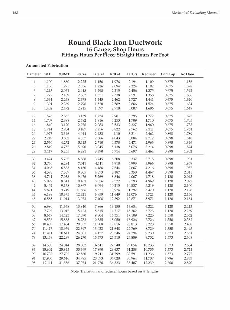
168 Mechanical Estimating Manual
Round Black Iron Ductwork16 Gauge, Shop Hours
Fittings Hours Per Piece; Straight Hours Per Foot
Automated Fabrication————————————————————————————————————————————
Diameter 90T 90RdT 90Crs Lateral RdLat LatCrs Reducer End Cap Ac Door————————————————————————————————————————————
4 1.100 1.880 2.225 1.156 1.976 2.194 1.109 0.675 1.156 5 1.156 1.975 2.336 1.226 2.094 2.324 1.192 0.675 1.578 6 1.213 2.071 2.448 1.298 2.215 2.456 1.275 0.675 1.592 7 1.272 2.169 2.562 1.371 2.338 2.591 1.358 0.675 1.606 8 1.331 2.268 2.678 1.445 2.462 2.727 1.441 0.675 1.620 9 1.391 2.369 2.796 1.520 2.589 2.866 1.524 0.675 1.634 10 1.452 2.472 2.915 1.597 2.718 3.007 1.606 0.675 1.648
———————————————————————————————————————————— 12 1.578 2.682 3.159 1.754 2.981 3.295 1.772 0.675 1.677 14 1.707 2.898 2.482 1.916 3.253 1.709 1.710 0.675 1.705 16 1.840 3.120 2.976 2.083 3.533 2.227 1.960 0.675 1.733 18 1.714 2.904 3.487 2.256 3.822 2.762 2.211 0.675 1.761 20 1.977 3.346 4.014 2.433 4.10 3.314 2.462 0.898 1.789 22 2.249 3.802 4.557 2.386 4.043 3,884 2.712 0.898 1.818 24 2.530 4.272 5.115 2.710 4.578 4.471 2.963 0.898 1.846 26 2.819 4.757 5.690 3.045 5.138 5.076 3.214 0.898 1.874 28 3.117 5.255 6.281 3.390 5.714 5.697 3.464 0.898 1.902
———————————————————————————————————————————— 30 3.424 5.767 6.888 3.745 6.308 6.337 3.715 0.898 1.931 32 3.740 6.294 7.511 4.111 6.918 6.993 3.966 0.898 1.959 34 4.065 6.835 8.150 4.486 7.544 7.667 4.216 0.898 1.987 36 4.398 7.389 8.805 4.873 8.187 8.358 4.467 0.898 2.015 38 4.741 7.958 9.476 5.269 8.846 9.067 4.718 1.120 2.043 40 5.092 8.541 10.163 5.676 9.522 9.793 4.969 1.120 2.072 42 5.452 9.138 10.867 6.094 10.215 10.537 5.219 1.120 2.100 44 5.821 9.749 11.586 6.521 10,924 11.297 5.470 1.120 2.128 46 6.198 10.375 12.321 6.959 11.649 12.076 5.721 1.120 2.156 48 6.585 11.014 13.073 7.408 12.392 12.871 5.971 1.120 2.184
———————————————————————————————————————————— 50 6.980 11.668 13.840 7.866 13.150 13.684 6.222 1.120 2.213 54 7.797 13.017 15.423 8.815 14.717 15.362 6.723 1.120 2.269 58 8.649 14.423 17.070 9.804 16.351 17.109 7.225 1.350 2.362 62 9.536 15.885 18.782 10.835 18.050 18.926 7.726 1.350 2.382 66 10.459 17.404 20.557 11.908 19.816 20.813 8.228 1.350 2.438 70 11.417 18.979 22.397 13.022 21.648 22.769 8.729 1.350 2.495 74 12.411 20.611 24.301 14.177 23.546 24.794 9.230 1.573 2.551 78 13.439 22.299 26.270 15.373 25.510 26.889 9.732 1.573 2.608
———————————————————————————————————————————— 82 14.503 24.044 28.302 16.611 27.540 29.054 10.233 1.573 2.664 86 15.602 25.845 30.399 17.890 29.637 31.288 10.735 1.573 2.721 90 16.737 27.702 32.560 19.211 31.799 33.591 11.236 1.573 2.777 94 17.906 29.616 34.785 20.573 34.028 35.964 11.737 1.796 2.833 98 19.111 31.586 37.074 21.976 36.323 38.407 12.239 2.700 2.890
————————————————————————————————————————————Note: Transition and reducer hours based on 4’ lengths.

Heavy Gauge Ductwork 169
Round Black Iron Ductwork16 Gauge, Angle Ring Connection, Installation Labor
Fittings Hours Per Piece; Straight Hours Per Foot———————————————————————————————————
45RE Sq/Rnd 90RE Sq/Elbw Diameter Straight Wye Trans Tap Offset
——————————————————————————————————— 4 0.151 0.544 0.540 0.133 0.540 5 0.179 0.643 0.585 0.144 0.585 6 0.206 0.743 0.630 0.155 0.630 7 0.234 0.842 0.675 0.166 0.675 8 0.262 0.942 0.720 0.176 0.720 9 0.289 1.042 0.765 0.187 0.765 10 0.317 1.141 0.810 0.198 0.810
——————————————————————————————————— 12 0.372 1.341 0.900 0.220 0.900 14 0.428 1.640 0.990 0.241 0.990 16 0.483 1.739 1.080 0.263 1.080 18 0.538 1.938 1.170 0.284 1.170 20 0.594 2.138 1.260 0.306 1.260 22 0.649 2.337 1.350 0.328 1.350 24 0.704 2.536 1.440 0.349 1.440 26 0.760 2.735 1.530 0.371 1.530 28 0.815 2.935 1.620 0.392 1.620
——————————————————————————————————— 30 0.871 3.134 1.710 0.414 1.710 32 0.926 3.333 1.800 0.436 1.800 34 0.981 3.532 1.890 0.457 1.890 36 1.037 3.732 1.980 0.479 1.980 38 1.092 3.931 2.070 0.500 2.070 40 1.147 4.130 2.160 0.522 2,160 42 1.203 46329 2.250 0.544 2.250 44 1.258 4.529 2.340 0.565 2.340 46 1.313 4.728 2.430 0.587 2.430 48 1.369 4.927 2.520 0.608 2.520
——————————————————————————————————— 50 1.424 5.126 2.610 0.630 2.160 54 1.535 5.525 2.790 0.673 2.790 58 1.645 5.924 2.970 0.716 2.970 62 1.756 6.322 3.150 0.760 3.150 66 1.867 6.721 3.330 0.803 3.330 70 1.978 7.119 3.510 0.846 3.510 74 2.088 7.518 3.690 0.889 3.690 78 2.199 7.916 3.870 0.932 3.870
——————————————————————————————————— 82 2.310 8.315 4.050 0.976 4.050 86 2.420 8.713 4.230 1.019 4.230 90 2.531 9.112 4.410 1.062 4.410 94 2.642 9.510 4.590 1.105 4.590 98 2.752 9.909 4.770 1.148 4.770
———————————————————————————————————Note: Angle ring connection labor is included with per piece labor.

170 Mechanical Estimating Manual
Round Black Iron Ductwork16 Gauge, Angle Ring Connection, Installation Labor
Fittings Hours Per Piece; Straight Hours Per Foot
——————————————————————————————————— 90T 90RdT 90Crs Diameter Lateral RdLat LatCrs Reducer BlastGt
——————————————————————————————————— 4 0.443 0.473 0.503 0.604 0.900 5 0.530 0.566 0.601 0.715 0.956 6 0.619 0.660 0.702 0.825 1.012 7 0.710 0.757 0.803 0.936 1.069 8 0.802 0.855 0.907 1.047 1.125 9 0.897 0.955 1.013 1.157 1.181 10 0.993 1.057 1.120 1.268 1.237
——————————————————————————————————— 12 1.192 1.266 1.341 1.490 1.350 14 1.397 1.483 1.568 1.711 1.462 16 1.610 1.707 1.803 1.932 1.575 18 1.831 1.938 2.046 2.154 1.688 20 2.058 2.171 2.296 2.375 1.800 22 2.294 2.423 2.553 2.596 1.912 24 2.536 2.677 2.818 2.818 2.025 26 2.786 2.938 3.090 3.039 2.138 28 3.043 3.206 3.369 3.261 2.250
——————————————————————————————————— 30 3.308 3.482 3.656 3.482 2.362 32 3.580 3.765 3.950 3.704 2.475 34 3.859 4.056 4.252 3.925 2.587 36 4.146 4.354 4.561 .4.146 2.700 38 4.440 4.659 4.877 4.368 2.813 40 4.742 4.972 5.201 4.589 2.925 42 5.051 5.292 5.532 4.811 3.037 44 5.367 5.619 5.871 5.032 3.150 46 5.691 5.954 6.216 5.235 3.262 48 6.022 6.296 6.570 5.475 3.375
——————————————————————————————————— 50 6.361 6.645 6.930 5.696 3.487 54 7.060 7.367 7.674 6.139 3.712 58 7.788 8.117 8.447 6.582 3.938 62 8.546 8.898 9.249 7.024 4.162 66 9.334 9.707 10.081 7.467 4.387 70 10.151 10.547 10.942 7.910 4.612 74 10.998 11.416 11.833 8.353 4.838 78 11.874 12.314 12.754 8.796 5.063
——————————————————————————————————— 82 12.780 13.242 13.704 9.238 5.287 86 13.715 14.199 14.683 9.681 5.512 90 14.680 15.186 15.692 10.124 5.737 94 15.674 16.203 16.731 10.567 5.962 98 16.698 17.249 17.799 11.010 6.188
———————————————————————————————————Note: Angle ring connection labor is included with per piece labor. Reducer labor based on 4’ lengths.

Heavy Gauge Ductwork 171
Rolled Steel Angle Rings

172 Mechanical Estimating Manual
Example of Round Black IronTakeoff and Extension
Per Piece Duct Takeoff Sheet

Heavy Gauge Ductwork 173
Aluminum
Uses Shower exhausts Locker exhausts Pool exhausts
Limitations and Problems Structurally weak Low pressure systems only Aluminum to aluminum doesn’t slide well 800 degree maximum temperature Crackage, slittage, metal fatigue
Gauges Use gauge numbers for heavier than LP galvanized. Aluminum gauges usually referred to in 1000ths of an inch. Galvanized weighs about 3-1/4 as much as aluminum.
Example: 20x10 LP galv. weighs 7 lbs/LF w/20% aluminum 20x10 2.32 lbs/LF
——————————————————————————————— Galv LF ALUMINUM
Gauges Gauge Thickness lbs/SF Duct Size Range
26 22 .025 .353 0-12
24 20 .032 .452 13-30 16 gauge or heavier
22 18 .040 .564 31-54 can be welded
20 16 .050 .706 55-84
18 14 .063 .889 85 up
——————————————————————————————— Types of Aluminum Use 3003 or 1100, soft or * hard.
Connections Start bar cleats and reinforcing angles at 18” wide instead of 24” “S” and bar cleats can be used; metal fl anges; and companion angles.
Reinforcing Need double the amount of reinforcing angles that galvanized LP does, both in intermediate locations and at connections.
Budget Pricing Typical exhaust system, .032” thick, 25% fi ttings by weight. Standard height run. Labor $39.00/hour, Materials $.65/lb, 20% allowance for waste, cleats, hangers, seams and hardware. $12.90/lb $5.83/sq ft
Labor Productivity Rates In square feet per hour: 33 sq ft/hr, Field 19 sq ft/hr In pounds per hour: 12 lb/hr, Field 7 lb/hr

174 Mechanical Estimating Manual
Rectangular Heavy Gauge Ductwork14 Gauge Aluminum, Angle Flange Connection
Shop HoursFittings Hours Per Piece; Straight Hours Per Foot
Manual Fabrication————————————————————————————————————————————
Sq/Elbw Size Straight 90 Elbw 45 Elbw Trans Tap Wye Sq/Rd Offset Door
———————————————————————————————————————————— 12x12 1.25 1.93 1.44 1.44 1.14 1.70 3.63 2.17 1.53 18x12 1.44 2.31 1.74 1.68 1.34 2.01 4.03 2.52 1.60 24x12 1.64 2.69 2.02 1.92 1.55 2.32 4.42 2.87 1.67 30x12 1.82 3.07 2.31 2.15 1.75 2.63 4.82 3.23 1.74
———————————————————————————————————————————— 36x12 2.01 3.46 2.59 2.39 1.95 2.93 5.25 3.58 1.81 36x18 2.20 3.84 2.88 2.62 2.15 3.25 5.76 3.93 1.88 42x18 2.39 4.84 3.63 2.86 2.35 3.56 6.26 4.28 .1.95 48x18 2.58 —5.28 3.96 3.09 2.55 3.86 6.76 4.64 2.02
———————————————————————————————————————————— 54x18 2.76 5.72 4.30 3.33 2.76 4.17 7.26 4.99 2.09 60x18 2.95 6.17 4.63 3.56 2.96 4.48 7.77 5.34 2.16 72x18 3.33 9.23 6.93 4.03 3.36 5.10 8.78 6.05 2.30 84x18 3.70 10.41 7.81 4.50 3.76 5.72 9.78 6.75 2.44
————————————————————————————————————————————
Automated Fabrication————————————————————————————————————————————
Sq/Elbw Size Straight 90 Elbw 45 Elbw Trans Tap Wye Sq/Rd Offset Door
———————————————————————————————————————————— 12x12 1.68 2.59 1.94 1.94 1.53 2.28 4.87 2.90 2.05 18x12 1.94 3.10 2.33 2.25 1.80 2.69 5.40 3.38 2.15 24x12 2.19 3.61 2.71 2.57 2.07 3.11 5.93 3.85 2.24 30x12 2.44 4.12 3.09 2.88 2.34 3.52 6.46 4.32 2.33
———————————————————————————————————————————— 36x12 2.69 4.63 3.47 3.20 2.61 3.93 7.04 4.79 2.47 36x18 2.94 5.14 3.86 3.51 2.88 4.35 7.71 5.27 2.52 42x18 3.20 6.48 4.86 3.83 3.15 4.76 8.39 5.74 2.62 48x18 3.45 7.07 5.31 4.14 3.42 5.18 9.06 6.21 2.71
———————————————————————————————————————————— 54x18 3.70 7.67 5.75 4.46 3.69 5.59 9.73 6.68 2.81 60x18 3.95 8.27 6.20 4.77 3.96 6.00 10.40 7.16 2.90 72x18 4.46 12.37 9.28 5.40 4.50 6.83 11.75 8.10 3.08 84x18 4.96 13.94 10.46 6.03 5.04 7.66 13.10 9.05 3.27
————————————————————————————————————————————

Heavy Gauge Ductwork 175
STAINLESS STEEL
Uses Utilized in laboratories, kitchens, plants, schools, for fume exhausts, dishwashers, pool exhausts, showers, locker rooms, ovens, open face tanks, etc.
Advantages Resists chemical corrosion excellently, doesn’t rust or stain, and withstands erosion very well.
Disadvantages It is more diffi cult to shear, cut drill punch, to work with in general due to it’s hardness. Dulls tools faster;
Rectangular Heavy Gauge Ductwork14 Gauge Aluminum, Angle Flange Connection
Field HoursFittings Hours Per Piece; Straight Hours Per Foot
———————————————————————————————— 45 Elbw Sq/Elbw 90 Elbw Trans Size Straight Wye Offset Tap Sq/Rd
———————————————————————————————— 12x12 1.20 1.08 1.20 0.29 0.87 18x12 1.43 1.28 1.43 0.35 1.01 24x12 1.65 1.49 1.65 0.40 1.16 30x12 1.88 1.69 1.88 0.45 1.31
———————————————————————————————— 36x12 2.10 1.89 2.10 0.51 1.45 36x18 2.33 2.09 2.33 0.56 1.59 42x18 2.55 2.30 2.55 0.62 1.73 48x18 2.78 2.50 2.78 0.67 1.88
———————————————————————————————— 54x18 3.00 2.70 3.00 0.72 2.02 60x18 3.23 2.90 3.23 0.78 2.16 72x18 3.68 3.31 3.68 0.89 2.45 84x18 4.13 3.71 4.13 0.99 2.74
————————————————————————————————
heavier capacity machinery needed. Surface has to be pro-tected from scratches and mars in processing if exposed. It is heavier than other corrosion resistant ductwork such as PVC or FRP. Material cost is far higher than regular steel.
Material Costs Runs from $1 to $2 per pound depending on the quantity purchased, fi nish required, sheet sizes, gauge and if protective covering is needed. Average $2.60/lb.
Material Calculations It’s best to fi gure the actual sheet sizes needed rather than the weight per linear foot with a more or less arbi-trary waste factor, because of the high cost.

176 Mechanical Estimating Manual
Example Cost Breakdown of Typical Duct Runs—with labor productivity rates.
24 Gauge (.987 lb/sq ft) 18 Gauge (2.016 lb/sq ft) Cleats & Pittsburghs Welded Seams, SM Flanges Item Sq Ft/Hr Cost/Sq Ft Sq Ft/Hr Cost/Sq Ft Material $ 2.76 $5.30 Shop 30 1.33 10 4.00 Field 17 2.28 15 2.66 Drawings 145 0.28 145 0.29 Cartage 300 0.10 0.06 Total Direct Costs 6.75 12.37 Mark Up, 35% 2.34 4.32
Budget Figures, sell $9.10 sq ft $16.68 sq ft Labor based on $39.00/hour
Rectangular Heavy Gauge Ductwork14 Gauge Stainless Steel, Angle Flange Connection—Shop Hours
Fittings Hours Per Piece; Straight Hours Per Foot
Manual Fabrication————————————————————————————————————————————
Sq/Elbw Size Straight 90 Elbw 45 Elbw Trans Tap Wye Sq/Rd Offset Door
———————————————————————————————————————————— 12x12 2.80 4.31 3.23 3.23 2.55 3.80 8.11 4.84 3.41 18x12 3.23 5.16 3.88 3.75 3.00 4.49 9.00 5.63 3.58 24x12 3.65 3.01 4.51 4.28 3.45 5.18 9.88 6.41 3.74 30x12 4.06 6.86 5.15 4.80 3.90 5.86 10.76 7.20 3.89
———————————————————————————————————————————— 36x12 4.49 7.71 5.79 5.33 4.35 6.55 11.73 7.99 4.05 36x18 4.90 8.56 6.43 5.85 4.80 7.25 12.85 8.78 4.20 42x18 5.33 10.80 8.10 6.38 5.25 7.94 13.98 9.56 4.36 48x18 5.75 11.79 8.85 6.90 5.70 8.63 15.10 10.35 4.51
———————————————————————————————————————————— 54x18 6.16 12.78 9.59 7.43 6.15 9.31 16.21 11.14 4.68 60x18 6.59 13.78 10.34 7.95 6.60 10.00 17.34 11.93 4.83 72x18 7.43 20.61 15.46 9.00 7.50 11.39 19.59 13.50 5.14 84x18 8.26 23.24 17.44 10.05 8.40 12.76 21.83 15.08 5.45
————————————————————————————————————————————
Automated Fabrication————————————————————————————————————————————
Sq/Elbw Size Straight 90 Elbw 45 Elbw Trans Tap Wye Sq/Rd Offset Door
———————————————————————————————————————————— 12x12 2.24 3.45 2.58 2.58 2.04 3.04 6.49 3.87 2.73 18x12 2.58 4.13 3.10 3.00 2.40 3.59 7.20 4.50 2.86 24x12 2.92 4.81 3.61 3.42 2.76 4.14 7.90 5.13 2.99 30x12 3.25 5.49 4.12 3.84 3.12 4.69 8.61 5.76 3.11
———————————————————————————————————————————— 36x12 3.59 6.17 4.63 4.26 3.48 5.24 9.38 6.39 3.24 36x18 3.92 6.85 5.14 4.68 3.84 5.80 10.28 7.02 3.36 42x18 4.26 8.64 6.48 5.10 4.20 6.35 11.18 7.65 3.49 48x18 4.60 9.43 7.08 5.52 4.56 6.90 12.08 8.28 3.61
———————————————————————————————————————————— 54x18 4.93 10.22 7.67 5.94 4.92 7.45 12.97 8.91 3.74 60x18 5.27 11.02 8.27 6.36 5.28 8.00 13.87 9.54 3.86 72x18 5.94 16.49 12.37 7.20 6.00 9.11 15.67 10.80 4.11 84x18 2.61 18.59 13.95 8.04 6.72 10.21 17.46 12.06 4.36
————————————————————————————————————————————

Heavy Gauge Ductwork 177
Rectangular Heavy Gauge Ductwork14 Gauge Stainless Steel, Angle Flange Connection
Field HoursFittings Hours Per Piece; Straight Hours Per Foot
———————————————————————————————— 45 Elbw Sq/Elbw 90 Elbw Trans Size Straight Wye Offset Tap Sq/Rd
———————————————————————————————— 12x12 2.00 1.80 2.00 0.49 1.45
18x12 2.38 2.14 2.38 0.58 1.69
24x12 2.75 2.48 2.75 0.66 1.94
30x12 3.13 2.81 3.13 0.75 2.18————————————————————————————————
36x12 3.50 3.15 3.50 0.85 2.41
36x18 3.88 3.49 3.88 0.94 2.65
42x18 4.25 3.83 4.25 1.03 2.89
48x18 4.63 4.16 4.63 1.11 3.13————————————————————————————————
54x18 5.00 4.50 5.00 1.20 3.36
60x18 5.38 4.84 5.38 1.30 3.60
72x18 6.13 5.51 6.13 1.48 4.08
84x18 6.88 6.19 6.88 1.65 4.56————————————————————————————————
FRP—FIBERGLASS REINFORCEDPLASTIC DUCTWORK
Uses Primarily used in corrosive exhaust systems for chemicals, acids, caustics, etc.
Advantages It is relatively light weight in comparison to steel, highly corrosive resistant, structurally stronger than plas-tic ductwork, can be worked in a wider range of tempera-tures, can be molded into many shapes and seals almost perfectly.
Description FRP is a combination of 1/16” thick laminated lay-ers of fi berglass mesh and epoxy and resin. The plastic is sprayed onto wood molds in the various duct confi gura-tions. Then stranded fi berglass mesh is laid over it which in turn is covered with spray. This process goes on until the desired thickness is attained.
Connections Connections can be fl anged, slip over, coupling or butt type and are chemically fi eld welded.
Materials run 1/8”, 3/16”, 1/4” thick depending on the duct size and application, and cost an average of $3.00 per square foot.
Budget costs installed, for the typical mix and average size, is approximately $16.05/sf This is based on $39.00/hr labor, $3.86/sq ft for material and a 35% markup for overhead.
Fabrication is highly specialized with the chemical pro-cess, molds, expertise and it is normally better to purchase the ductwork from a FRP manufacturer. It runs about S 10. 50 per square foot depending on the mix of fi ttings and straight duct, and on the average size.

178 Mechanical Estimating Manual
PVC DUCTWORK
Uses Used in corrosive exhaust systems, fume, chemical, mist, etc. and is resistant to many chemicals.
Advantages PVC is lightweight, it can be bought in sheets, and it can be easily cut, formed, heat welded or joined with a solvent.
Description
Materials PVC is a poly vinyl chloride, smooth surface, thermo plastic. Usually 1/8” thick sheets are used for smaller ducts and 3/16” thick for larger ones. Materials cost about $3.86/sf
Connections Connections are generally, either fl anged or coupling.
Fabrication Sheets Fabrication sheets can be cut in a shear or with a saw. There are four methods for bending material; you can put the sheet in a long fl at oven and when heated to the proper temperature, remove it and bend it. A second method is with an electric calrod which is laid on the sheet on the bend line, the line is heated and then bent in a hand brake. The third method is with a torch and the fourth with a heat table and asbestos.
Seams and Connections Seams and connections can be chemically welded with a solvent that fuses the material together, heat welded with a torch, or with a wire feed welding gun that runs at 40” per minute.
Shop Labor runs about 23 sf/hr for typical mixes of fi ttings, pipe and sizes.
Field Labor productivity rate average 16 sq ft/hr.
Budget Figures typical mix, average size $13.10/sq ft.

Heavy Gauge Ductwork 179
PVC COATED GALVANIZED
Uses Used either in corrosive exhaust systems for fumes, chemicals, acids, caustics or for underground HVAC sup-ply systems.
Description PVC coated galvanized, commonly called by its reg-istered trade name “PVS,” is galvanized material with a protective coat of corrosion resistant PVC on it. It comes in either sheets of rectangular ductwork, spiral pipe and
Per Piece Labor FRP, PVC and AluminumFlanged Connections
Straight Duct and Fittings Mixed
————————————————————————————————————— Semi FRP PVC Aluminum 16 GA Size Perim Shop Field Shop Field Shop Field
————————————————————————————————————— 12 x 6 18 1.9 1.4 0.9 1.3 1.8 1.3 12 x 12 24 2.0 1.5 1.0 1.4 1.9 1.4
————————————————————————————————————— 18 x 12 30 2.3 1.7 1.2 1.6 2.1 1.5 18 x 18 36 2.5 1.8 1.3 1.7 2.3 1.6
————————————————————————————————————— 24 x 12 36 2.6 1.9 1.3 1.8 2.4 1.7 24 x 18 42 2.8 2.1 1.4 2.0 2.6 1.9
————————————————————————————————————— 30 x 12 42 2.9 2.3 1.5 2.2 2.7 2.0 30 x 18 48 3.1 2.5 1.6 2.3 2.9 2.2
————————————————————————————————————— 36 x 12 48 3.2 2.6 1.7 2.4 3.0 2.3 36 x 18 54 3.6 2.9 1.9 2.7 3.3 2.6 36 x 24 60 3.8 3.0 2.0 2.8 3.5 2.7
————————————————————————————————————— 42 x 18 60 3.9 3.0 2.0 2.9 3.6 2.7 48 x 18 66 4.3 3.2 2.3 3.0 4.0 2.8 48 x 24 72 4.6 3.3 2.4 3.1 4.2 2.9
————————————————————————————————————— 54 x 18 72 4.8 3.4 2.5 3.2 4.4 3.0 60 x 18 78 5.2 3.8 2.7 3.6 4.8 3.4 66 x 18 84 5.4 4.3 2.8 4.1 5.0 3.8
————————————————————————————————————— 72 x 18 90 5.7 4.8 2.9 4.5 5.3 4.3 72 x 24 96 6.1 5.3 3.2 5.0 5.6 4.7
————————————————————————————————————— 78 x 24 102 6.3 5.8 3.3 5.4 5.9 5.1 84 x 24 108 6.6 6.2 3.5 5.8 6.1 5.5
—————————————————————————————————————
fi ttings, or in residential lock seam pipe and fi ttings. Usu-ally the corrosive side has a four mil thickness on it and the non corrosive side a one mil thickness.
Construction and Connections Rectangular ductwork fabricated from sheets can be seamed with pittsburghs, bent, sheared, etc. the same as regular galvanized. Where the PVC coating may be scratched or marred it can be touched up. Connections can be “S” and drive cleats or fl anged metal. Either PVC tape and cement or hardcast tape can be used to seal con-nections.

180 Mechanical Estimating Manual
Material PVC coated galvanized comes in various gauges 26, 24, 22 etc. The most commonly used gauges are 24 and 22. Typical cost is about $2.37 per square foot for 24 gauge sheets.
Labor Fabrication labor runs an average of 30 sq ft/hr. In-stallation is typically 17 sq ft/hr.
Budget Costs Typical budget installed cost for average 24 gauge system with 25% fi ttings by square feet runs $8.83/sq ft.
LABOR MULTIPLIERSFOR HEAVY GAUGE DUCTWORK
The following labor multipliers should be applied for various conditions:
1. If two exact DUPLICATE fi ttings are being fabri-cated, reduce the time 33% on the second elbow be-cause of the saving on the layout time. Both elbows can be further reduced 10% because of set up time savings on a production run approach.
2. Fabrication labor can be reduced 33%, if TEM-PLATES are being used in the hand layout of the gores.
3. A fast working highly skilled sheet metal layout man can work 25% to 50% faster than the average mechanic.
To relate your own productivity rates to the Super-Duct program you must fi rst of all adjust the per piece labor factors on an overall basis for your company, and then adjust factors for individual job conditions such as duplications, templates, etc. Also, duct specs must be set up properly for plasma cutters, stick or wire feed welding, continuous or tack weld, type welding machinery used, etc. before making takeoff so that proper labor factors are activated.
SAMPLE LABOR TESTSON ROUND BLACK IRON ELBOWS
The following table shows the fabrication labor vari-ations for a 48” dia, 90 degree, 5 gore elbow with angle rings welded on when done by hand, on a plasma cutter or with a gore cutting machine:
Shop Field
10 ga 14 ga 10 ga 14 ga
Hand Layout and Cut 21.14 17.62 7.94 5.47
With Plasma Cutter 15.86 13.72 7.94 5.47
With Gore Machine 13.96 11.63 7.94 5.47
The hours calculated are based on the custom fabri-cation of a single item, with individual layouts and sepa-rate setups of machinery. No templates are being used in the hand fabricated sample.
AIR POLLUTION ESTIMATING
Air pollution control and industrial exhaust ventila-tion work today comprise a major industry of more than $2 billion annually. Among the factors that have contributed to the strength of this industry are social concern over the qual-ity of air both inside and outside environments; OSHA and EPA monitoring and policing; increased realization of the actual damages of uncontrolled pollutants, including black lung, cancer, blindness, crippling, and death; and the many lawsuits fi led by those injured by uncontrolled contaminants. A large portion of air pollution control work occurs in processing plants of major industries such as chemi-cal, coal mining, pharmaceutical, woodworking, etc., fol-lowed by manufacturing plants, laboratories, restaurants, auto repair garages, etc. Items and operations that require exhausting in-clude boilers, ovens, kilns, dryers, welding,’ soldering, painting, and metal cleaning and treating. Additional op-erations include waste conveying, milling, spraying, cool-ing, raw product handling, crushing, grinding, screening, grating, bagging and packing, polishing, buffi ng, melt-ing, burning, and shakeout.The costs of air pollution control systems can vary from 11¢ per cfm for a simple propeller fan installed in a wall or window to exhaust smoke to $6 to $7 per cfm for a complex open tank exhaust system including makeup air, special ducts, hoods, etc. For contractors engaged in design and construction, these installations may carry with them a risk in terms of performance. If a system is improperly designed, or if at-tempts to keep costs down result in an inadequate system, the consequences can be costly. A $5,000 collector may have to be replaced with a $ 10,000 unit or hoods remade at a contractor’s expense. To estimate costs completely and accurately, the contractor must be knowledgeable of the basic engineering principles and considerations in-volved in properly designing workable systems.

Heavy Gauge Ductwork 181
The Purpose of Control The purpose of an air pollution control system is to:1) Remove harmful contaminants such as dusts, fumes,
mists, vapors, gases, and heat from a source area.
2) Transport them through ducts to a collector or fan.
3) Separate the contaminants from the air and either reclaim or dispose of them, or discharge the mixture directly to the atmosphere if permissible.
ENGINEERING FUNDAMENTALS
Contaminants include anything that is harmful to humans, animals, plants, or property in the internal or external environment. There are two basic categories of contaminants, particulates and gases. Particulates are small solid or liquid particles such as dusts, powders, smoke, liquid droplets, and mists. Fly-ash from coal furnaces and asbestos dusts are examples of harmful particulate pollutants. Gas pollutants are fl uids without form that occupy space rather uniformity, such as carbon monoxide or chloroform. A fume is an irritating smoke, vapor, or gas. Contaminants are measured in microns. A micron is smaller than the point of a sharpened pencil. There are 10,000 microns in a centimeter, 25,400 in 1 inch. Particles smaller than 2 microns are visible only with an electronic microscope, those between 2 and 10 microns with a stan-dard microscope, and those larger than 10 microns with the naked eye. Pollen and lint range in size from approximately 5 to 70 microns; smoke from approximately 0.001 to 1 mi-cron. averaging approximately 0.1, and 90 percent of at-mospheric dusts are approximately 0.25 microns in size, but they can range up to 30 or 40 microns. An important consideration in air pollution control is the harmful effects of the contaminants involved. Pol-lutants can be toxic (poisonous, possibly fatal) or noxious (harmful to health but not necessarily deadly). They may be corrosive (alkalis, acids, salts, and caustics) or erosive (causing wearing away by abrasion). Processes can be heat producing, moisture producing, or smoke producing, causing uncomfortable or harmful levels. Odors my be offensive or harmful. Pollutants can be infl ammable, ex-plosive, or radioactive. And fi nally, contaminants include bacteria and viruses. Fire and explosion hazards are critical factors. Dusts as well as many fumes and mists have fl ash point temperatures, at which spontaneous combustion occurs,
and explosive limits, which are percentage ranges defi n-ing when explosion occurs. There are two fl ash points for a hazardous pollut-ant, one for a closed situation and the other for an open situation. There are also two explosive limits, a lower and an upper. For example, ethyl acetate has fl ash points of 24°F and 30°F and lower and upper explosive limits of 2.18 and 11.4 percent. Similarly, methanol has fl ash points of 54°F and 60°F and explosion limits of 6.72 and 36.5 per-cent. With regard to toxicity, the point at which a mixture of pollutant and air starts to become toxic is called it’s threshold limit value. There are also different levels of acceptable concentrations for different lengths of expo-sure. Threshold limits and prolonged exposure limits are usually stated in terms of ppm, parts of contaminants per million parts of air, at a certain temperature and pressure. For example, ammonia has a threshold limit value of 25 ppm, a daily exposure limit of 100 ppm, and a 1/2 to 1 hour exposure limit of 2500 ppm; it is rapidly fatal at 5000 ppm. Other measures of contaminant concentration or density sometimes used in pollution control work in-cludes weight per cubic foot, pounds per hour, grains of moisture-per pound of air, percentage of gas, and others. Another important factor affecting the performance of a system is the settling rate of a solid or liquid par-ticles. This is a measure of the time it takes for a particle to fl oat down and come to rest, and is dependent on particle size. A 50 micron particle will free fall at 14.8 fpm whereas a 1 micron particle will free fall at 0.007 fpm. Thus, the former will fall almost 15 ft in 1 minute; the latter will take approximately 36 hours to fall the same distance.
AIR POLLUTION SYSTEM DESIGN
The general procedure in system design is to iden-tify the problem, analyze the problem, establish facts, de-termine the magnitude of the pollution problem, calcu-late capacities, design hoods and ductwork, select system components (collectors, fans, makeup air units, etc.), and choose an appropriate disposal method. (See fi gure on following page.) Some of the important considerations in this area are:
Capture Velocity One of the major considerations involved in the design of an air pollution control system is the velocity required to pick up the contaminants from their source area. This velocity is called the capture velocity, and it

182 Mechanical Estimating Manual
must overcome spillage, air and heat currents, and the contaminants’ weight and velocity. For example, labora-tory fumes heavier than air may require a capture veloc-ity at their point of emission of 50 fpm to overcome their tendency to spill to the fl oor as well as any currents of air fl owing across the source area. Sawdust, which weighs approximately 12 lb/cuft, usually requires a suction pres-sure of 2.5 in. WG for proper pickup.
Transport Velocity The air velocity required in the duct to carry the material, overcome resistance and turns, lift it in risers, and convey it to a collector or fan is the transport velocity. Powdered coal requires a transport velocity of approxi-mately 4000 fpm.
Hood Face VelocityThis is the velocity required at the face of a hood for prop-er contaminant pickup and suction into the hood. A typi-cal slot hood face velocity might be 2000 fpm; a kitchen exhaust hood might require a face velocity of only 100 to 150 fpm. Hoods must be designed to draw in pollut-ants properly. Pollutants can be captured by completely enclosing the source area, by providing a local hood at the exact point of emission, or by providing a general ex-haust hood or grille. There are an infi nite number of hood confi gurations, and the best designs are those in which contaminants project directly into the hoods. For exam-ple, particulates from grinding, buffi ng, polishing, or saw wheels should be propelled directly into their hoods. For heat removal, fumes should rise into their hoods.
Air Volume Factors that determine the volume of air required are the surface area of the source, the quantity of material
Collector effi ciency ranges
being removed, the amount of dilution required, the size of hood opening, and the face velocity. A kitchen hood with a 30 sq ft opening and a 100 fpm face velocity re-quires 3000 cfm.
Ductwork There are two general approaches to designing a duct system. One is the balanced static regain approach, in which the system is automatically balanced through exact pressure design of the ductwork This can be done when all hoods are used whenever the system is in operation. The second basic approach involves blast gates. Dampers are put in branches to control air fl ow, and the system is not designed to be automatically balanced. Here, veloci-ties are the main consideration. Total system static pres-sure is contingent on the run with the greatest resistance as well as on the pressure drops of the collector and other components.
Velocity Some systems are designed for 100 percent usage of hoods all the time, others for only partial use of hoods at any one time. In sizing collectors and fans, the diversity factor must be taken into account to determine whether they should handle 80, 60, or some other percentage of the design air volume and static pressure. If only 60 per-cent of a sys tem is in operation at any given time, it is very costly to size for larger capacities.
Material removal rate Another factor that must be integrated into the design is the removal rate for dusts, particles, etc. The density of the material, its concentration in the air stream, the quantity of air involved, and the quantity of material to be removed must be considered to arrive at an ultimate removal rate.

Heavy Gauge Ductwork 183
ReferencesIndustrial Ventilation, A Manual of Recommended Practice, 15th ed.,
American Conference of Governmental, Industrial Hy-
gienists, Committee on Industrial Ventilation, Lansing,
Michigan, 1978.
Alden, John, and Kane, John, Design of Industrial Exhaust Sys-
tems, 4th ed., Industrial Press, Inc., New York, 1970.
ASHRAE Handbook & Product Directory, 1976 systems, Chapters
21-23, American Society of Heating, Refrigerating and
Air-conditioning Engineers, Inc., New York.
Wendes, Herbert C., Everything You Ever Wanted to Know About
Sheet Metal Estimating, Wendes Systems, Inc., Arlington
Heights, Illinois, 1976.
COST ESTIMATING PROCEDURES
In general, the cost estimating procedure is as fol-lows:
1. If the system is not yet designed, the fi rst step is to develop an effective and economic design that will
Air Pollution EstimateScope and Check List
—————————————————————————————————————————Scope and checklist for air pollution control estimates. Many items must be included in an industrial exhaust or air pollution control estimate, and some of them are easily missed. Great care must therefore be taken to make sure they are all accounted for. This table provides a checklist but is not necessarily all inclusive.
EQUIPMENT❐ Collectors❐ Platforms❐ Ladders❐ Stands❐ Fans❐ Screw Conveyors❐ Dampers❐ Makeup Air Equipment❐ Heat Recovery Equipment❐ Blast Gates❐ Starters❐ Pumps❐ Compressors❐ Vibration Isolators❐ Inlet Vane Dampers❐ Louvers❐ Shutters
DUCTWORK❐ Black Iron
❐ Stainless Steel❐ Aluminum❐ Galvanized❐ Aluminized Steel❐ Corten❐ PVC❐ PVC Coated Galvanized❐ FRP❐ Flues❐ Flexible Tubing
SHEET METAL SPECIALTIES❐ Hoods❐ Dampers❐ Turning Vanes❐ Hoppers❐ Platforms❐ Flex Connections❐ Access Doors❐ Walk Thru Doors❐ Gaskets
❐ Sealants❐ Painting Ducts
SPECIAL LABOR❐ Shop Drawings❐ Field Measuring❐ Cartage❐ Testing and Balancing❐ Startup❐ Service
SUBS, RENTALS❐ Gas Piping❐ Water Piping❐ Pneumatic Piping❐ Electrical❐ Temperature Controls❐ Concrete Pads❐ Crane❐ Cutting and Patching
perform properly and meet codes.
2. If the system is already designed, a thorough study of the plans and specifi cations is required so that the estimator will be familiar with all of the require-ments and the scope of the project.
3. Equipment suppliers and subcontractors should be notifi ed.
4. The estimator makes his/her takeoff of ductwork, sheet metal specialties, and equipment.
5. Calculations are run on ductwork, specialty mate-rial and labor.
6. All items are transferred to a summary sheet. Any pricing not yet done is fi lled in, labor is extended, and all purchases and labor are to be totaled.
7. Markups, taxes, permits, increases, etc., are applied in a recap.

184 Mechanical Estimating Manual
Smyth Lighting Fixture PlantSample Estimate
Open Surface Tank Exhaust System

Heavy Gauge Ductwork 185
Estimate Summary and Extension Sheet

This page intentionally left blank
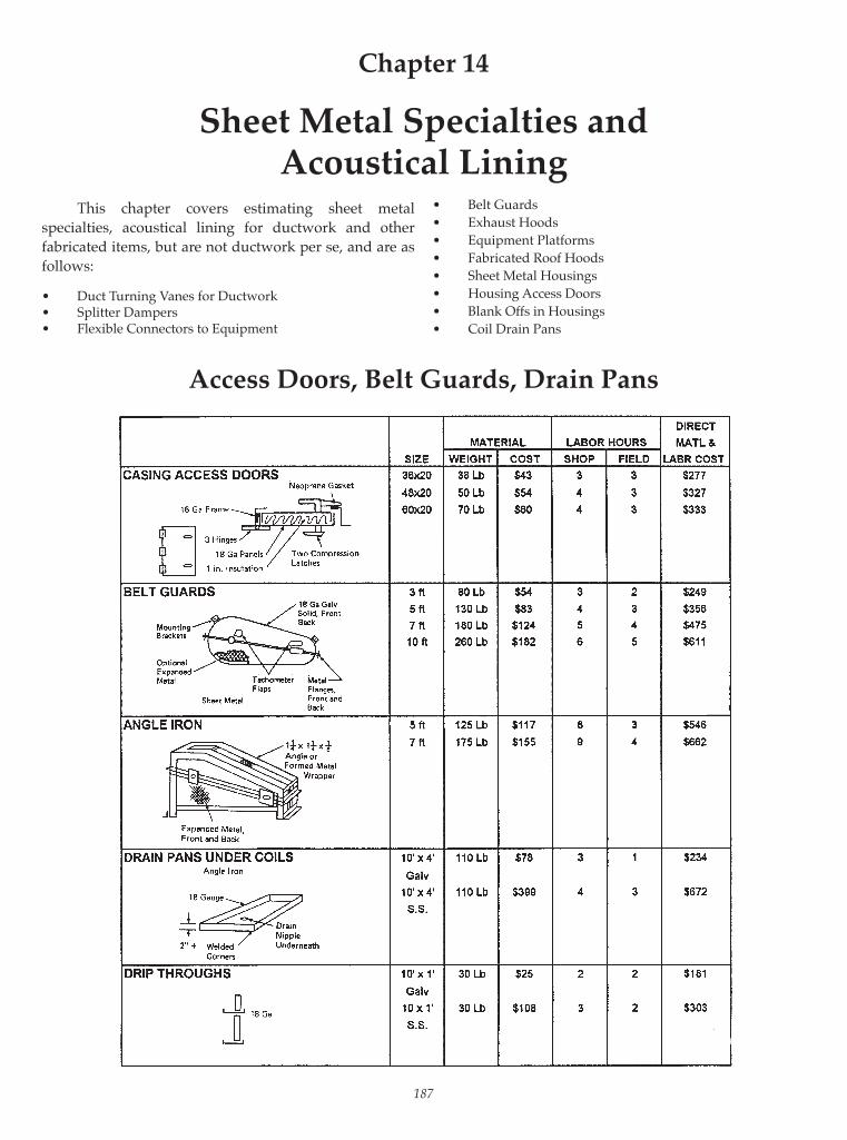
187
Access Doors, Belt Guards, Drain Pans
This chapter covers estimating sheet metal specialties, acoustical lining for ductwork and other fabricated items, but are not ductwork per se, and are as follows:
• Duct Turning Vanes for Ductwork• Splitter Dampers• Flexible Connectors to Equipment
Chapter 14
Sheet Metal Specialties andAcoustical Lining
• Belt Guards
• Exhaust Hoods
• Equipment Platforms
• Fabricated Roof Hoods
• Sheet Metal Housings
• Housing Access Doors
• Blank Offs in Housings
• Coil Drain Pans

188 Mechanical Estimating Manual
Flexible Connections, Hoods, Stands and Platforms

Sheet Metal Specialties and Acoustical Lining 189
Roof Hoods

190 Mechanical Estimating Manual
Turning Vanes
WeightTwo inch air foil weighs about 4.2 lbs/sq ft assembledDuct width has to be multiplied by 1.4 trip factor tocome up with true length.
Costs to Purchase Formed LengthApproximately $0.74 per lb. in uncut, unassembled pieces, vanes and rails (2” vanes, $0.36/LF) (rails, $0.37/LF)
————————————————————————————————————————————— SEMI- TOTAL PERIM DIRECT LABOR MATERIAL & LABOR SIZE ——— WEIGHT SQ FT MATERIAL ——— ————————— COST Man Direct With Inches Lbs 45 Diag. Hours Cost 30% O&P
————————————————————————————————————————————— 12x6 18 3 0.7 $3.11 0.3 $14.81 $19.25 12x12 24 6 1.4 6.22 0.3 17.92 23.29 18x12 30 9 2.1 9.32 0.4 24.92 32.40 24x12 36 12 2.8 12.43 0.5 31.93 41.51
————————————————————————————————————————————— 30x12 42 15 3.5 $15.54 0.6 $38.94 $50.62 30x24 54 29 7.0 30.04 0.8 61.24 79.62 36x12 48 18 4.2 18.65 0.8 49.85 64.80 36x18 54 26 6.3 26.94 0.8 58.14 75.58 36x24 60 35 8.4 36.26 0.9 71.36 92.77
————————————————————————————————————————————— 42x18 54 31 7.4 $32.12 0.9 $67.22 $87.38 42x36 78 62 14.7 64.23 1.2 111.03 144.34 48x18 66 35 8.4 36.26 1.0 75.26 97.84 48x36 84 71 16.8 73.56 1.3 124.26 161.53 54x18 72 40 9.5 41.44 1.1 84.34 109.64 54x36 90 79 18.9 81.84 1.4 136.44 177.38
————————————————————————————————————————————— 60x18 78 44 10.5 $45.58 1.2 $92.38 $120.10 60x36 96 88 21.0 91.17 1.5 149.67 194.57 72x18 90 53 12.6 54.91 1.5 113.41 147.43 72x36 108 106 25.2 109.82 1.8 180.02 234.02 72x54 126 159 37.8 164.72 2.6 266.12 345.96 84x18 102 62 14.7 64.23 1.8 134.43 174.76 84x36 120 123 29.4 127.43 2.0 205.43 267.06 84x54 138 185 44.1 191.66 3.0 308.66 . 401.26
—————————————————————————————————————————————
Correction Factors on 2” Air Foil Material Labor 1. Single skin vanes, 2” radius 0.90 0.80 2. Air foil vanes, 4” radius 2.00 0.80 3. Single skin vanes, 4” radius 1.30 0.70
Labor hours include, time to cut, assemble and install.

Sheet Metal Specialties and Acoustical Lining 191
Splitter Dampers
————————————————————————————————————————————— SEMI- TOTAL PERIM DIRECT LABOR MATERIAL & LABOR SIZE ——— WEIGHT SQ FT MATERIAL ——— ————————— COST Man Direct With Inches Lbs 45 Diag. Hours Cost 30% O&P
————————————————————————————————————————————— 9x9 18 24 0.8 $5.27 0.3 $16.97 $22.06 18x12 30 22 2.6 6.22 0.3 17.92 23.29 30x16 46 20 6.7 8.41 0.5 27.91 36.28 42x18 60 20 9.0 9.61 0.5 29.11 37.84 54x20 74 20 13.0 12.98 0.8 42.23 54.90 66x24 88 is 29.0 22.01 0.8 51.26 66.63 78x30 108 18 43.0 30.06 1.0 69.06 89.78
—————————————————————————————————————————————
Takeoff and Pricing Methods
1. Determine approximate average size and multiply labor and material costs times total quantity.
2. Add one linear foot of ductwork for each splitter damper to cover labor and material.
3. Takeoff each individually and price in size groups.

192 Mechanical Estimating Manual
SHEET METAL HOUSINGS
Built up sheet metal housings are fi eld assembled casings used to enclose HVAC component equipment such as fi lters, coils, fans, water eliminators, dampers, etc.
Construction Casings are built in panels with standing seams or channel fl anges, 20”, 26”, 32” or 44” wide by lengths of anywhere between 5 and 10 feet and are normally 18 gauge. (See fi gure below.)
Material Calculations1. Measure size of housing and calculate square foot-
age.2. Add 30% for waste, seams and hardware.3. Measure required angles and add 15% waste.
A typical full size panel is 32” wide seam to seam, 8 feet long, requires an 18 gauge 36x96 sheet which weighs 52 pounds and costs $23.34 per sheet at $.42/lb.
Labor Single Skin PanelsFabrication 1/2 hr/panel 36 sf/hr 64 lbs/hrInstallation 2 hr/panel 9 sf/hr 20 lbs/hr
Includes angle and caulking labor.
Budget FiguresSingle skin $160/panel $9.42/SF $4.10/lbDouble skin $314/panel $17.41/SF $8.71/lb
Labor and budget fi gures are based on an average 32” wide by 6 foot long panel, which is a typical size in a mix, single skin, 18 gauge galvanized, 39 lbs per panel, $39.00/hr, $.40/lb, 30% waste allowance and a 30% markup for overhead and profi t.
Correction Factors Double skin, 2” thick, 2” internal insulation, and perforated inner panel.
Material costs ................. 3.0 Shop labor ....................... 3.0 Field labor ....................... 1.5
ACOUSTIC LINING
The main purpose of internal lining is to absorb sound, but it can also function simultaneously as a ther-mal insulator when needed. Sometimes it is simply used in place of insulation for economic or other reasons.
Uses Lining is used in auditoriums, libraries, in outside ductwork, in high pressure ductwork off of a fan, on the low pressure side of high pressure terminal units. Lining is not used in fume or partial exhaust indus-trial exhaust systems, in hot systems such as kitchen ex-haust, in wet or moist situations such as with dishwash-ers, showers and pool exhausts.
Description Fiberglass lining comes in 2 basic types blanket and rigid board. (See fi gure on following page.)
Calculating Material1. If you have the square footages just add 15% for
waste and corner overlaps.
2. If you only have poundage fi gures you have to con-vert them back to square feet by dividing the weight per square foot for each gauge into the poundage to get back to the square footage.

Sheet Metal Specialties and Acoustical Lining 193
Example: 26 ga 5,000 lbs .906 lbs/sq ft = 5,519 sq ft
24 ga 15,000 lbs 1.156 lbs/sq ft = 12,519 sq ft
22 ga 8,000 lbs 1.406 lbs/sq ft = 5,690 sq ft
20 ga 4,000 lbs 1.656 lbs/sq ft = 2,415 sq ft
18 ga 2,000 lbs 2.156 lbs/sq ft = 928 sq ft
If the poundage fi gures already have the standard 20% waste in them, you them must reduce the square feet 5% to bring it down to 15%.
Material Cost 1” thick, 1-1/2 lb density ...........$0.43/sq ft
1/2” thick, 2 lb density ..............$0.35/sq ft
Cement and Pins, add ................$0.10/sq ft
Increased Duct Size Increase the metal duct size to cover the lining thick-ness. For example, increase a 20 x 10 duct to 22 x 12 for 1” thick lining. Weight increases about 12 percent for aver-age duct sizes for 1 inch thick lining and 6 percent for 1/2 inch thick.
Labor (Based on 1” thick, 1-1/2 lb density, blanket.)
Correction Factors on Labor1. 1” thick, 3 lb .........................................................1.152. 2 inch thick, 1-1/2 lb ..........................................1.15
Square Feet Per Hour————————————————————————————————
Ratio
Fitting Maximum Width of Duct
SqFt to 0-12” 13-30” 31-54” 55-84” 185 and up
Total SqFt 26 ga 24 ga 22ga 20 ga 18 ga————————————————————————————————
Str Duct Only 54 80 84 98 112
10-20% 46 58 70 82 94
20-30% 41 57 62 73 83
30-40% 38 45 55 66 74
40-50% 35 43 50 58 66
Fittings only 24 30 35 41 47————————————————————————————————\

194 Mechanical Estimating Manual
3. Rigid Board, 1” thick ..........................................1.50 Rigid Board, 1-1/2 “ thick .................................1.75 Rigid Board, 2” thick ..........................................2.004. 1/2” thick blanket, 1-1/2 lb .................................85
Budget Figures1. Typical lining: 1” thick, 1-1/2 lb, 30% markup, $1.75/sq 1/2” thick, 1-1/2 lb, 30% markup, $1.46/sq

195
DRAFTING AND SKETCHING LABOR
Miscellaneous labor covers additional operations which are not directly installation work. This may include shop drawings, sketching, cartage, testing and balancing, operation and maintenance manuals, sleeves and chases, excavating and backfi lling, removal work, cutting and patching openings, etc. Fully detailed, 1/4 inch scale, offi ce prepared shop drawings with locations, elevations, outlet locations, fi t-ting details, pipe and fi tting lengths, walls, partitions, and refl ected lights and beams all shown.
Labor Labor includes the preparation of the shop draw-ings, revisions, fi eld checks, making out shop fabrication tickets, and listing blankouts. It is a function of the quantity of pieces of ductwork rather than the weight, fi ttings taking twice the total amount of time than straight pipe sections. It is also de-pendent on congestion in the ceiling space of all the me-chanical, electrical work, on the complexity of the duct
runs, and the extent of the architectural, structural com-plexity in the particular area.
Straight pipe .............................................. .10 hr/pc Fittings ....................................................... .20 hr/pc Typical 50/50 mix, straight duct and fi ttings, by quantity pieces .......... .15 hr/pc
On a pounds per hour basis for an average mix of gauges: Mix 10-20% fi ttings by weight 23 5 lbs/hr Mix 20-30% fi ttings by weight 200 lbs/hr Mix 3040% fi ttings by weight 185 lbs/hr Mix 40-50% fi ttings by weight 175 lb/hr Pipe only 350 lbs/hr Fittings only 100 lb/hr
Correction Factors Clear, open areas or straight runs ................... 0.7 Congested ceiling spaces .................................. 1.2 Equipment room ................................................ 1.2 Heavy duplications ........................................... 0.8 Complete duplication of area .......................... 0.6
Chapter 15
Miscellaneous Labor Operations

196 Mechanical Estimating Manual
Budget Figures Galvanized ductwork: 230 per pound 260 per square foot of ductwork
FIELD MEASURING AND SKETCHING LABOR
Final Duct Connections Final duct and fl exible connections to units, fans, louvers, etc.: 120lbs/hr or 50hr/pc, based on size of 48”x24”.
Complete Duct Runs Measure area, obstructions, sketch run, fi gure lengths, elevations, draw fi ttings—30% fi ttings by weight.
0-800 lbs 24 gauge avg 120 lbs/hr .25 hr/pc 22 gauge avg 200 lbs/hr .25 hr/pc————————————————————————— 800 lbs up 24 gauge avg 150 lbs/hr .2 hr/pc 22 gauge avg 300 lbs/hr .2 hr/pc
Budget Figures for New Projects Use 5% of total metal weight for fi nals and for mea-suring sheet metal specialties.
Ex. 50,000 lb job x 5% = 2500 lbs divided by120 lbs/hr = 21 hrs total
Hence fi eld measuring averages out to about 2000 lbs/hr or 2.50/lb based on total weight of job.
SERVICE
Two methods of calculating service and punch list work:1. 2 hours per piece of equipment2. 5% of the cost of heating, refrigeration, air handling
equipment
ESTIMATING AIR TESTING AND BALANCING
Balancing Procedures The labor fi gures in this section are based on the fol-lowing air testing and balancing procedures.
1. Prepare test reports• Assemble plans, specs, equipment cuts, Ak fac-
tors.• Survey and plan balancing.• Determine instruments to use.• Draw schematics.• List outlets on outlet sheet.• Determine Ak factors and calculate required ve-
locities.
2. Start up• Check motor name plates, starter overload,
heater size, fan, type wheel, rotation, drives, bearings, fi lters, etc.
• Check and set automatic dampers.• Checkout dampers in duct runs, and at outlets
and inlets. Check terminal units.• Clean up debris.• Turn fan on and take start up readings: amp,
volts, fan rpm, total, CFM fan static pressure.
3. Balance duct runs and outlets proportionately.
4. Reread equipment and adjust as required.
5. Finalize reports.
Instruments The labor fi gures are also based on using the follow-ing instruments:
Volt-Ammeter Pitot TubeRPM Counter Inclined Draft GaugesRotating Vane Anemometer Magnehelic GaugesAlnor Velometer Thermometers

Miscellaneous Labor Operations 197
Start Up Labor Includes checkout of equipment, setting automatic dampers, reading amps, volts, fan rpm, fan static pres-sure and total CFM.
Hours
Supply units .........................................................................4.0
Multi-zone units (plus .5 hours per zone) .......................3.0
Centrifugal exhaust fans ....................................................3.0
Roof exhaust fans ................................................................2.0
Fan-coil units ........................................................................2.0
Dust collectors ......................................................................3.0
Correction Factors on start up labor Multipliers
1. If no S.P. or total CFM readings
are taken on supply units ........................................... 0.70
2. Typical units ................................................................. 0.90
Balancing Outlets and Inlets Based on 8 to 12 foot high ceilings, 2 to 3 passes, 3 to 4 readings each, using fl ow hood.
Smaller Larger
Simpler Complicated
Diffusers Systems Systems
6”-24” .....................................................0.35 0.50
26” up ....................................................0.50 0.70
Linear diffusers, per 5 foot length .....0.40 0.60
Light troffers, per slot ..........................0.30 0.40
Grilles, registers
0-4 SF ......................................................0.35 0.50
4-8 SF ......................................................0.40 0.60
8 up SF ...................................................0.50 0.70
Exhaust hoods ...........................................0.40 0.60
Terminal UnitsHigh pressure boxes: access through ceiling .....................0.50
access by crawling in ceiling .........0.80
Induction units: under windows ...............................0.50
in ceiling ...........................................1.00
Test ReportsFill out equipment sheets, each system ...............................0.20
Fill out and fi nalize outlet sheets, per outlet .......................0.12
Draw schematic layout, per outlet ........................................0.05
Rule of thumb: all test reports, 10% of all fi eld balancing work.
Correction Factors Multipliers
1. Ceiling height; 8 to 12 feet ................................................ 1.00
13 to 18 feet .............................................. 1.15
19 feet and up ......................................... 1.25
2. Floor 1-5 ........................................................................ 1.00
6-15 ...................................................................... 1.10
16-30 .................................................................... 1.20
31 and up ............................................................ 1.25
3. Occupied areas .................................................................. 1.15
4. Hazardous industrial exhaust areas .............................. 1.25
Budget Figures Includes all operations from preparing reports through startup, balancing and fi nalizing reports.Figures are based on low pressure systems, single zone, low rise building, 8 to 12 foot high ceilings, 1 to 2 outlets per room, a typical mixture of outlet sizes and CFMs and that there are several systems on the job.
PER OUTLET
Average Budget
Hours Each
Smaller, simpler systems: 0.75 $40
Larger, complicated systems: 1.00 $47

198 Mechanical Estimating Manual
Example Testing and Balancing Estimate
——————————————————————————————————— Hours
Qty. Item Each Total———————————————————————————————————
1 Supply unit Start Up 4.0 1 Return air fan 3.0 1 Roof exhaust fan 2.0
24 Diffusers (typical .9 x .5 = .45) Bal. .45 10.8 2 12x12 grilles .5 1.0 2 48x36 grilles 0.7 1.4
2 Pitot tube traverse in branch duct .6 1.2
3 Equipment sheets Test Reports .2 .6 28 Outlet sheets .12 3.4 28 Schematic drawing .05 1.4
1 Change RPM .75 Gross total 29.55
——————————————————————————————————— Small simple job .9 x 29.55 = Net total 26.6
——————————————————————————————————— Average per outlet 26.6 ÷ 28 = .95hrs
———————————————————————————————————

Miscellaneous Labor Operations 199
1. Set up leak testing rig 1.0 hr2. Cap and seal ends of duct run, 1/2 hr each 1.0 hr3. Cap and seal branch collars, 16 at .2 hrs each 3.2 hr4. Check leakage with fan, walk run, seal 2.0 hr5. Retest 1.0 hr Total time for segment 8.2 hrs
ESTIMATING HYDRONIC BALANCING
Check Out Equipment HoursPumps: Check out pump itself, motor, starter, adjacent valves; read pressures, gpm, amps volts; adjust. 1.5 to 2.5Chillers, Absorption Units 2.0 to 3.0Cooling Tower 5.0 to 10.0Central Cooling and Heating Coils 2.0 to 4.0
Balancing TerminalsReheat Coils, Radiation Units .75 to 1.25Induction Units, Fan Coil Units .75 to 1.25
Estimating Ductwork Leak TestingMedium or High Pressure Duct Runs
LABOR FOR TYPICAL DUCT RUN

200 Mechanical Estimating Manual
DRAWING, CARTAGE❐ Cartage❐ Shop Drawings❐ Field Sketching
TESTING, BALANCING, SERVICE❐ Testing and Balancing❐ Pressure Testing❐ Monitoring❐ Service❐ Operation and Maintenance Manuals
MISCELLANEOUS❐ Initial Set Up of Job❐ Clean Up of Job
GENERAL CONSTRUCTION WORK❐ Sleeves❐ Chases❐ Excavate❐ Backfi ll
REMOVAL WORK❐ HVAC Equipment❐ Ductwork❐ Piping❐ Electrical❐ Remove and Replace Partitions❐ Ceilings❐ Remove and Replace Doors❐ Remove and Replace Windows❐ Cut Openings❐ Patch Openings❐ Remove and Replace Ceilings❐ Paint❐ Protect Furnishings and Equipment❐ Scrap items❐ Clean Up
Miscellaneous Labor OperationsCheck Off List

Section V
Piping Estimating

This page intentionally left blank

REQUIREMENTS OF A PROFICIENT ESTIMATOR
A profi cient and reliable piping estimator must possess the following background knowledge, skills and abilities:
Estimating Principles and Procedures He must follow sound effi cient procedures for preparing estimates, such as:
• Become thoroughly familiar with the project, the types of systems and piping, valves etc., involved in the scope of work, etc. before starting a detailed takeoff.
• Be familiar with budget estimating piping systems, costs for different type buildings and systems based on: Cost per square foot of building or cost per ton of air conditioning, Amount of piping per square foot of building, The average size of piping on a job, Cost of piping per linear foot, Cost per square foot of building of piping.
• Know the major divisions of an estimate as described in “8 Facets of the Estimating Diamond” in Chapter 1: Equipment Piping, Valves Accessories, Specialties Special Labor Sub-Contractors End of Bid Factors (such as
sales tax) Markups for Overhead and Profi t
• Must be familiar with detailed scope of what is required in a piping estimate.
• Identify and highlight various types of pipe, fi ttings, valves, etc. on drawings before the takeoff.
• Follow systematic overall procedures as described in chapter 2. Study the plans and specs. Send out quotation requests Make Takeoffs and Extensions
Chapter 16
Piping Estimating Basics
Summarize Recap and Markups
• Do constant systematic checking on each part as you go along and overall at the end. Double check everything.
Blue Print Readings Must have the ability to read blue prints, recognize symbols, types of pipe lines, types of equipment and systems, etc.
Types of Piping Systems Must be knowledgeable of the types of piping
systems there are such as:• Low, medium and high temperature hot water
systems.• Low, medium and high pressure steam systems.• Chilled water cooling systems• Refrigeration systems.• Hot and cold water systems.• Oil and gas piping.
He must not only recognize the various types of systems on plans, but he must know all of the components required in them, whether shown on plans or not. They must know about different types of piping system confi gurations such as:• 1,2,3 and 4 pipe systems• Reverse and direct return• Constant and variable volume• Closed and open systems
Piping and Fitting Materials A piping estimator must know about different types of pipe and fi tting materials, manufacturing methods, types of fi ttings in each category and applications to systems.
Black Steel Pipe: Sch 20, 40 and 80, A53, A120, A106, Seam and Seamless Pipe, TC and PE ends
Black Fittings: Malleable, Butt Weld, Forged and Black Cast Iron Fittings
Copper Tubing: L, K, K ACR, Soft and Hard Tubing, plus DWV
203

204 Mechanical Estimating Manual
Copper Fittings: Wrought and Cast FittingsPressure PVC: Sch 40, 80, Socket and Threaded Pipe
and FittingsGalvanized Pipe: Sch 40 and 80Galvanized Fittings: MalleableCast Iron Soil Pipe: Hub and Spigot, No Hub
Material Applications He must know the applications of different types of pipe and fi tting materials to various systems:
Recirculating Water, 2500°F For 2” diameter and under Black Steel A53 Seam, Sch 40 Threaded Pipe Malleable Threaded Fittings For 2-1/2” to 12” diameter Black Steel A53 ERW Welded Pipe Butt Weld Fittings
Steam and Condensate For 2” diameter and under, 90 lb Black Steel A53 Seam, Sch 40 Threaded Pipe Cast Iron Threaded Fittings For 2-1/2” to 12”, 250 lb Black Steel Standard Welded Pipe Wrought Steel Welded Fittings
Refrigerant Copper L, Y, ACR Hard Tubing, Brazed Wrought Copper Pressure Fittings, Brazed
Underground Water Through 12” diameter, 350 lb Copper Y, Hard Tubing, Soldered Wrought Copper Pressure Fittings, Soldered
Portable Water Inside Building, 350 lb Copper & Hard Tubing, Soldered Wrought Copper Pressure Fittings, Soldered
Fittings He must be familiar with different types of fi ttings and those available with all the different types of materials:
Long and Short Radius 90° and 45° Elbows Straight and Reducing Tees Concentric and Eccentric Reducers Straight and Reducing 45° Laterals Caps, Plugs, Unions, Adapters and Couplings Weldolets, Threadolets and Sockolets Threaded, Slip on and Welded Neck Flanges Straight and reducing Wye Fittings, DW
Combination Fittings, DW Bends, 1/8, 1/4, 1/6, etc., DAW Straight, Reducing Taps, Sanitary Crosses, DWV Traps, Cleanouts, DWV
Connections He must have thorough knowledge of the different types of piping connections. Steel: Threaded Butt Weld Flanged Grooved Socket Weld Copper: 95/5 Brazed PVC: Solvent Heat Fusion Threaded Cast Iron: Soil Pipe Hub and Spigot No Hub
Hangers He must be familiar with various types of hangers and supports such as: Clevis Roller Spring Riser Clamps
Labor• He must know sources of labor such as MCA and
NAPHCC association labor tables, other manuals available, cost records, etc.
• He must know the methods of estimating piping labor such as pipe per foot and fi ttings per piece or pure per joint labor method.
• He must apply labor multipliers when ever needed and do so with reasonable accuracy.
Piping Pricing He must know sources of pricing such as piping supply houses, list pricing services such as Harrison, Allpriser, Trade Services, etc. He must be able to use quotations, pricing estimating manuals, etc.
Valves He has to know about valves:
Standard Valves:• Bronze, Iron, Steel, Plastic, etc.• Gate, Ball, Globe, Butterfl y, Check, Angle
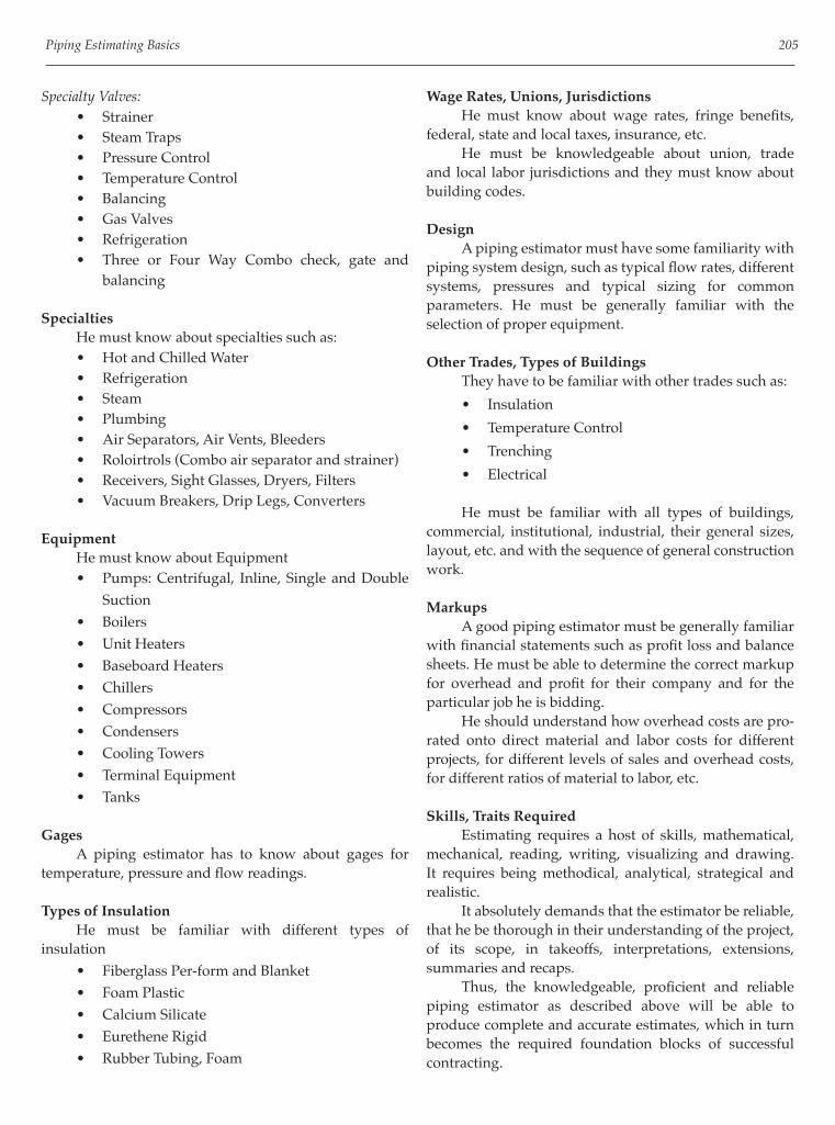
Piping Estimating Basics 205
Specialty Valves:
• Strainer
• Steam Traps
• Pressure Control
• Temperature Control
• Balancing
• Gas Valves
• Refrigeration
• Three or Four Way Combo check, gate and
balancing
Specialties He must know about specialties such as:
• Hot and Chilled Water
• Refrigeration
• Steam
• Plumbing
• Air Separators, Air Vents, Bleeders
• Roloirtrols (Combo air separator and strainer)
• Receivers, Sight Glasses, Dryers, Filters
• Vacuum Breakers, Drip Legs, Converters
Equipment He must know about Equipment
• Pumps: Centrifugal, Inline, Single and Double
Suction
• Boilers
• Unit Heaters
• Baseboard Heaters
• Chillers
• Compressors
• Condensers
• Cooling Towers
• Terminal Equipment
• Tanks
Gages A piping estimator has to know about gages for temperature, pressure and fl ow readings.
Types of Insulation He must be familiar with different types of insulation
• Fiberglass Per-form and Blanket
• Foam Plastic
• Calcium Silicate
• Eurethene Rigid
• Rubber Tubing, Foam
Wage Rates, Unions, Jurisdictions He must know about wage rates, fringe benefi ts, federal, state and local taxes, insurance, etc. He must be knowledgeable about union, trade and local labor jurisdictions and they must know about building codes.
Design A piping estimator must have some familiarity with piping system design, such as typical fl ow rates, different systems, pressures and typical sizing for common parameters. He must be generally familiar with the selection of proper equipment.
Other Trades, Types of Buildings They have to be familiar with other trades such as:
• Insulation
• Temperature Control
• Trenching
• Electrical
He must be familiar with all types of buildings, commercial, institutional, industrial, their general sizes, layout, etc. and with the sequence of general construction work.
Markups A good piping estimator must be generally familiar with fi nancial statements such as profi t loss and balance sheets. He must be able to determine the correct markup for overhead and profi t for their company and for the particular job he is bidding. He should understand how overhead costs are pro-rated onto direct material and labor costs for different projects, for different levels of sales and overhead costs, for different ratios of material to labor, etc.
Skills, Traits Required Estimating requires a host of skills, mathematical, mechanical, reading, writing, visualizing and drawing. It requires being methodical, analytical, strategical and realistic. It absolutely demands that the estimator be reliable, that he be thorough in their understanding of the project, of its scope, in takeoffs, interpretations, extensions, summaries and recaps. Thus, the knowledgeable, profi cient and reliable piping estimator as described above will be able to produce complete and accurate estimates, which in turn becomes the required foundation blocks of successful contracting.

206 Mechanical Estimating Manual
HOW TO ESTIMATE PIPING SYSTEMS
This section of piping basics will cover how to takeoff and extend the various piping components in a piping estimate, piping, fi ttings, accessories (fl anges, hangers, connection materials, etc.) valves, specialties and equipment. It win cover what forms to use for larger projects and small jobs.
General Basis of Piping labor and Material Pricing The installation labor and material pricing for piping, fi ttings, valves and specialties is a function of the following characteristics:
Examples
Type Material: (Black, copper, etc.)
Type Item: (pipe, 90 Elbow, etc.)
Size: (1/2”, 3” diameter)
Type Connection: (threaded, welded, fl anged, etc.)
Type Hangers: (band, ring, clevis, etc.)
Hence the labor and pricing tables, takeoff and extension sheet divisions are mostly divided up in the above manner. Hangers usually are not a fundamental category and standard lengths of pipe may be a factor with certain materials.
General Takeoff Approach and Job Breakdown In making the takeoff, separate the job into different categories so that correction multipliers can be applied as required.
• Standard Floor Plans• Congested Areas• Crawl Space• High Piping Runs• Equipment Rooms• Higher Floors
The takeoff should be separated into different materials and type systems. e.g. Hot water heating, Black steel, Schedule 40, AW53
System P 1
Refrigeration System, Copper Tubing, Type L
System P2
Separate the takeoff into alternates so that alternate prices can be computed separately.
Equipment Hookups Stop or start takeoffs at the equipment before taking off risers going up or down and hooking up to the piece
of equipment. The hookups should be taken off separately and duplications should be treated as an assembly times the number pieces of equipment connected to. Then estimate the hookups separately.
Labor The labor factors in the tables are based on normal working conditions.• Non-productive supervision is not included.• For Job Conditions correction multipliers should be
applied.• Normal Material Handling is included.
Taking off Piping• Piping is taken off in footage and is listed
separately.• It is taken off per system, per material, type
connection and diameter.• Labor and pricing are computed on a per foot basis• Piping comes in various lengths, e.g. Black A53 is 21
feet long in the smaller size range.• Cuts are fi gured for pieces that are less than the
standard length.• Connection materials such as weld, solder, etc. or
fl anges, coupling are needed between pipe to pipe connections and must be counted and priced.
• Hanger sets are based on the footage of pipe and average spacing between sets, and must be counted and priced.
• The labor tables are generally based on an average of one piping connection for every fi ve feet of pipe.
• Certain piping, such as cast iron hub and spigot may be labored and priced per standard length, for example, per two or fi ve foot long standard section etc.
Taking off Fittings• Fittings are taken on an “each” basis and listed
separately from pipe on the takeoff sheets.• They are taken off per system, per material, type
connection and by diameter.• Connections materials such as weld, solder, putty,
etc. may be required at joints and need to be taken off, priced and labored.
• If the fi tting is a fl anged piping system or a connection to a piece of equipment with a fl ange, and the fi ttings are not fl anged, then separate fl anges that need to be taken off, price and labor them.
Large Projects; Takeoff Method and Extensions On large projects where numerous takeoff sheets are required, separate piping takeoff and extension sheets

Piping Estimating Basics 207
should be used as opposed to a combination takeoff and extension sheet.
1. Piping takeoff sheets are used for taking off piping, fi ttings, valves, etc. Each column is headed with the particular diameter, except the left hand column which is used for listing different type of fi ttings, valves, etc.
2. After the takeoff is complete the footages of pipe for each diameter are totaled, as well as the total quantities of fi ttings, valves, etc. for each diameter being totaled.
3. The totals per type piece and diameter etc. are transferred to a piping extension sheet and summarized.
4. Unit labor and pricing are looked up in the tables in this manual and extended for a total labor and price for each type and size.
5. The columns are then totaled on the extension sheet and transferred to a piping recap sheet for the totals per type of material and connection.
6. The totals of each category are then transferred from
the piping recap sheet to the estimate summary sheet for the job.
Small Job Takeoff and Extension Method1. On small projects where maybe only one or a few
takeoff and extension sheets are needed, the piping extension sheet is used for both the takeoff and extension of the piping, fi ttings, valves, etc.
2. In this case, sizes are simply listed in the left hand column, the type of item in the second column on the same line and the footages or quantities in the third column over.
3. After the takeoff is completed the footages and quantities are totaled in the middle column.
4. Unit material costs and erection labor hours are looked up, entered in the unit columns on the right hand side of the form and extended in the total columns.
5. The material and labor totals are then added up for either each category or for the entire sheet, and the numbers transferred to a job summary sheet accordingly.
SAMPLE ESTIMATEHot Water Heating System
Overview of Sample Piping Estimate
The sample piping system covers a hot water heating system for an offi ce building with hot water heating coils in three air handling units, black steel threaded and welded piping, malleable threaded and butt welded fi ttings, bronze and iron body valves, control and balancing valves. It contains a hot water boiler, compression tank, pump, three way valve, rolairtrol air eliminator, thermometers and pressure gauges, plus other miscellaneous items.
Purpose of Forms
Purpose of Forms Forms are an indispensable aid and guide to organized, effi cient and thorough estimating. They help control the proper sequence of estimating work, continually remind you of what information is needed, lead you logically through calculations and as a result your bids will be more complete and correct.
Job Description and Budget Costs Form (See form samples in chapter 3)

208 Mechanical Estimating Manual
1. Budget estimate prices to determine if it should be bid or not, and as a check price against the detailed estimate after the bid is complete.
2. Approximate heating and cooling loads and rough out total piping linear footage for check of detailed piping takeoff.
3. Record the key characteristics of the type of system involved.
Piping Takeoff Sheet
The piping takeoff sheet can be used for piping, fi ttings, valves, gages, strainers, etc on larger type projects. Estimating piping labor by the hours per foot, and estimating fi tting, valve, gage, strainer, etc. labor by the piece, is the most accurate and clearest method available for contractors. The takeoff involves listing the diameter, type, quantities on fi ttings, valves, etc. and lengths on pipe.
Piping Extension Sheet
The extension of material involves totaling piping footages per line, entering the labor per foot and extending totals. The extension of fi tting, valve, etc. labor involves totaling the quantity of pieces, looking up and entering labor hours per piece and multiplying out for the totals per line. The same procedure is followed for pricing. After the lines are extended the columns are totaled.
Combined Piping Takeoff and Extension Sheet
The combined piping and takeoff sheet is more practical for smaller projects involving fewer items and one or a few sheets. Sizes are listed horizontally in the left hand column, rather than in the column headings.
Equipment Takeoff and Extension Sheet
List all equipment, quantities, sizes, capacity, description on this combined sheet and enter purchase costs from quotations, pricing sheets if available. Enter labor to install equipment using labor tables in this manual or other sources.
Quantity Takeoff and Extension Sheet (See form samples in chapter 3)
The quantity takeoff sheet is a general form for taking off and listing types, sizes, quantities, etc. of the various items required in a bid other than ductwork or piping, for extending the material amounts, labor, costs, etc. and summations.
Estimate Summary and Extension Sheet (See form samples in chapter 3)
The summary sheet is used as a line item summary of all the major grouping of different items included in the estimate, from ductwork and other takeoff sheets, etc. It should be divided into the major divisions of a bid, quoted equipment, ductwork, piping, specialties and accessories, miscellaneous labor, etc. The total amounts of material quantities, labor, etc. are transferred from duct and piping takeoff sheets, piping extension sheets, quantity takeoff sheets etc. to this summary sheet.
Bid Recap Sheet (See form samples in chapter 3)
1. Recap the job totals of direct costs on labor and prices on raw materials, equipment and sub contractors, and to total them.
2. Put markups on each group and total the overhead markup.3. Put a profi t markup on the labor, raw material, equipment and sub-contractor groups.4. Total everything for a bottom line bidding price.

Piping Estimating Basics 209
Calculating Labor Costs Per Hour Form (See form samples in chapter 3)
This form insures that all the components of the wage rate which include, base wage rate, normal union fringe benefi ts, federal and state payroll taxes, insurance’s and dues, are covered in the rate used in a bid.
Telephone Quotations Form (See form samples in chapter 3)
The telephone quotation form is for recording quotations which come over the phone, in an organized, complete and readable fashion. It includes a check off list on the bottom of critical aspects of a quote such as, if they meet plans and specifi cation requirements, addendum’s, taxes, freight, lead times, etc. A box is provided for exceptions on what is not included.
Bidding Record Form (See form samples in chapter 3)
The purpose of the bidding record form is to have a written record of to whom the phone bids were given, what the amount was, what the inclusions and exclusions were and what the plans, specifi cations and addenda of the bids were based on.
Specifi cations on Sample Job
IBM Sales Offi ceA. Related Documents
The general provisions of the contract, the general conditions and supplementary
conditions of these specifi cations plus the A/A document A201-1976 “general
conditions” apply to the work in this specifi cation.
B. Scope of Work
Scope of work to include, but not be limited to the following:
Equipment Specialties
1. Boiler 15. Strainers
2. Roloirtrol 16. Drains
3. Centrifugal Pump
4. Hot Water Coils Gauges
5. Chemical Pot Feeder 17. Thermometers
6. Compression Tank 18. Pressure
7. Control Dampers
Miscellaneous
Piping 19. Test piping systems
8. Black Steel, Sch 40, A53, Threaded
9. Black Steel, Sch 40, A53, Welded Sub Contractors
20. Temperature Controls
Fittings 21. Insulation
10. Black Malleable Threaded
11. Black Steel Butt Welded C. Work Not Included
1. Painting
Valves 2. Power wiring to mechanical equip.
12. Bronze, Threaded 3. Structural steel openings
13. Iron Body 4. Concrete Pads
5. Starters
Specialties Valves
14. Control Balancing

210 Mechanical Estimating ManualS
amp
le H
ot
Wat
er H
eati
ng
Sy
stem

Piping Estimating Basics 211
Piping Takeoff Sheet

212 Mechanical Estimating Manual
Piping Extension Sheet

Piping Estimating Basics 213
Piping Extension Sheet

214 Mechanical Estimating Manual
Alternate MethodCombination Piping Takeoff and Extension for Small Jobs

Piping Estimating Basics 215
Equipment Takeoff and Extension Sheet

This page intentionally left blank

217
Chapter 17
Pressure Pipe, Fittings and Insulation
This chapter covers pressure pipe and fi ttings used for the following type systems:• Hot Water• Chilled Water• Refrigeration• Steam and Condensate• Oil and Gas• Hot and Cold Potable Water
This chapter further covers all types of the following pressure pipe and fi tting materials:• Black Steel• Galvanized• Carbon Steel• Malleable• Copper• Pvc
These tables in this chapter also covers all the normal type fi ttings involved in pressure type systems such as radius elbows, street elbows, tees, laterals, crosses, caps, plugs, unions, couplings, weldolets, etc. Standard type connections are covered, such as threaded, welded, grooved, soldered, solvent, etc. Flanges such as threaded, slip on and welded neck are also covered. Pricing for different types of pipe hangers such as band, clevis, roller, and riser clamps are included, plus standard hanger spacing, rod diameter tables, concrete inserts and anchors. Piping sleeves and cutting round openings are covered. At the end of this chapter are tables on insulation as follows: Fiberglass Blanket Fiberglass Preformed Foam Plastic Calcium Silicate Rigid Eurethene Foam Rubber Tubing
Units All diameters are in inches.
Labor The labor productivity rates in the tables are what the average mechanic under average conditions can erect on lower fl oors of construction projects. However, they may require the application of labor correction factors for variable conditions such as upper fl oors, higher piping runs, congested spaces, etc. The labor in the tables are in hours per piece and hours per foot for pipe.
Pricing and Discounts The pricing in the tables are based on the typical manufacturers list prices and the contractor’s supplier discounts must be applied. Appropriate price discounts can range from roughly 10 percent to 80 percent dependent on the following:
• Supplier discount structure
• Who manufacturer is
• Size of batch involved
• Availability
• Shipping distance, costs
Not All List Prices Are Publicly Available Where there are no prices listed in tables, they are not usually publicly available from the manufacturer. If there is neither labor nor prices listed for a particular diameter in the tables, the particular item may not be available or it may not be a commonly used item.
Caution With List Prices Pricing can sometimes vary signifi cantly because of changes in commodity material pricing such as copper, etc. Periodic checks of current list prices should be made. If in doubt about your discounts from list prices, check with your supplier as to what they are for the various categories of items—or request a quotation.

218 Mechanical Estimating Manual
Automatic UpdatingAvailable in Wendes Computer System Automatic updating of list pricing is available in the Wendes Computerized Piping Estimating System. Call (847) 808-8371 for more information.
Terminology Abbreviations TC pipe: Cut and threaded. PE pipe: Plain end. Thrd: Threaded connections. Weld: Welded connections. Grvd: Grooved connections.
Black BW A53 Schedule 40 Pipe Labor ——————————————————————— Hours per Foot
TC Pipe PE Pipe
Dia Thrd Weld Grvd——————————————————————— 1/8 0.04 0.05 ———————————————————————— 1/4 0.05 0.06 ———————————————————————— 3/8 0.05 0.06 ———————————————————————— 1/2 0.06 0.06 ———————————————————————— 3/4 0.06 0.06 0.06——————————————————————— 1 0.06 0.08 0.06——————————————————————— 1-1/4 0.08 0.08 0.07——————————————————————— 1-1/2 0.08 0.10 0.08——————————————————————— 2 0.10 0.13 0.09——————————————————————— 2-1/2 0.13 0.15 0.10——————————————————————— 3 0.16 0.17 0.12——————————————————————— 3-1/2 0.18 0.19 0.14——————————————————————— 4 0.20 0.23 0.16——————————————————————— 5 — 0.28 0.20——————————————————————— 6 — 0.32 0.25——————————————————————— 8 — 0.38 0.30——————————————————————— 10 — 0.45 0.35——————————————————————— 12 — 0.56 0.40——————————————————————— 14 — — 0.42——————————————————————— 16 — — 0.45——————————————————————— 18 — — 0.48——————————————————————— 20 — — 0.50——————————————————————— 24 — — 0.57
——————————————————————— Labor Factor
Black BW A53 Schedule 80 Pipe
Threaded TC Pipe over 2” Dia. 1.15
Welded PE Pipe all Diameters 1.20

Pressure Pipe and Fittings and Insulation 219
Black Malleable Standard FittingsThreaded Connection Labor
———————————————————————————————————————————
Threaded Labor Hours Each———————————————————————————————————————————
Brass
Dia 90 Elbow 45 Elbow Tee Wye Cross Cap Coupling Union———————————————————————————————————————————
1/8 0.14 0.09 0.16 0.25 0.13 0.15 0.23———————————————————————————————————————————
1/4 0.21 0.10 0.25 — 0.31 0.14 0.16 0.27———————————————————————————————————————————
3/8 0.28 0.22 0.38 0.45 0.45 0.15 0.21 0.31———————————————————————————————————————————
1/2 0.35 0.35 0.51 0.51 0.66 0.20 0.35 0.35———————————————————————————————————————————
3/4 0.46 0.46 0.70 0.70 0.95 0.25 0.46 0.50———————————————————————————————————————————
1 0.60 0.60 0.87 0.87 1.13 0.30 0.60 0.56———————————————————————————————————————————
1-1/4 0.70 0.70 1.00 1.00 1.32 0.36 0.70 0.63———————————————————————————————————————————
1-1/2 0.75 0.75 1.10 1.10 1.45 0.40 0.75 0.70———————————————————————————————————————————
2 0.90 0.90 1.35 1.35 1.75 0.46 0.90 0.95———————————————————————————————————————————
2-1/2 1.47 1.47 2.18 2.18 2.88 0.75 1.46 1.47———————————————————————————————————————————
3 1.76 1.76 2.62 2.64 3.46 0.90 1.74 1.76———————————————————————————————————————————
3-1/2 2.06 2.06 3.06 — — 1.04 — ————————————————————————————————————————————
4 2.37 2.37 3.53 3.55 4.64 1.19 2.32 ————————————————————————————————————————————
5 3.84 3.84 5.70 — — 1.93 — ————————————————————————————————————————————
6 4.65 4.65 6.89 — — 2.32 — ————————————————————————————————————————————
Labor Factor
Black malleable standard fi tting threaded XH 1.03

220 Mechanical Estimating Manual
Black Malleable Standard FittingsGrooved Connection Labor
—————————————————————————————————————————————————————
Grooved Labor Hours Each
22-1/2 Lateral Female Std Flex #150
Dia 90 Elbow 45 Elbow Elbow Tee Wye Cross Adapter Cap Coupling Flange—————————————————————————————————————————————————————
3/4 0.35 0.35 0.42 0.50 0.88 0.98 0.18 0.18 0.03 ——————————————————————————————————————————————————————
1 0.42 0.42 0.45 0.60 0.88 0.98 0.22 0.22 0.04 ——————————————————————————————————————————————————————
1-1/4 0.45 0.45 0.50 0.68 0.88 0.99 0.25 0.24 0.05 ——————————————————————————————————————————————————————
1-1/2 0.50 0.50 0.60 0.70 0.89 1.00 0.27 0.25 0.05 ——————————————————————————————————————————————————————
2 0.60 0.60 0.58 0.90 0.89 1.15 0.32 0.30 0.06 0.05 ——————————————————————————————————————————————————————
2-1/2 0.65 0.65 0.70 0.90 0.87 1.16 0.30 0.31 0.08 0.07—————————————————————————————————————————————————————
3 0.70 0.70 0.80 1.05 1.05 1.40 0.35 0.35 0.09 0.08—————————————————————————————————————————————————————
4 0.95 0.95 0.93 1.45 1.42 1.85 0.50 0.47 0.10 0.10—————————————————————————————————————————————————————
5 1.45 1.40 1.40 2.15 2.12 2.75 — 0.70 0.12 0.12—————————————————————————————————————————————————————
6 1.75 1.70 1.70 2.62 2.60 3.35 — 0.85 0.20 0.15—————————————————————————————————————————————————————
8 2.45 2.30 2.28 3.60 3.55 4.45 — 1.18 0.25 0.20—————————————————————————————————————————————————————
10 3.30 3.00 2.90 4.85 4.55 5.75 — 1.53 0.35 0.20—————————————————————————————————————————————————————
12 4.00 3.30 3.00 5.30 4.75 5.95 — 1.67 0.45 0.50—————————————————————————————————————————————————————
14 4.35 3.73 — 5.70 5.45 6.35 — — 0.70 0.70—————————————————————————————————————————————————————
16 5.05 4.10 — 6.14 5.80 6.55 — — 0.82 0.85—————————————————————————————————————————————————————
18 5.30 4.55 — 7.38 7.02 8.65 — — 0.84 0.90—————————————————————————————————————————————————————
20 6.15 5.30 — 8.25 8.05 9.95 — — 1.6 1.12—————————————————————————————————————————————————————
24 6.95 6.80 — 9.90 9.35 10.93 — — 1.62 1.53—————————————————————————————————————————————————————

Pressure Pipe and Fittings and Insulation 221
Carbon Steel Butt Weld Standard FittingsWelded Connection Labor
————————————————————————————————
Welded Labor Hours Each
90 LR 45 LR
Dia Elbow Elbow Tee Cross Cap————————————————————————————————
1/2 0.57 0.57 0.84 0.31————————————————————————————————
3/4 0.84 0.84 1.24 0.44————————————————————————————————
1 1.11 1.11 1.65 — 0.57————————————————————————————————
1-1/4 1.39 1.38 2.06 2.73 0.71————————————————————————————————
1-1/2 1.65 1.64 2.47 3.27 0.84————————————————————————————————
2 2.20 2.18 3.29 4.35 1.11————————————————————————————————
2-1/2 2.56 2.55 3.85 5.15 1.25————————————————————————————————
3 2.70 2.65 4.05 5.35 1.35————————————————————————————————
3-1/2 3.10 3.05 4.65 6.15 1.54————————————————————————————————
4 3.35 3.32 5.03 6.70 1.65————————————————————————————————
5 3.92 3.85 5.85 7.75 1.93————————————————————————————————
6 4.40 4.25 6.55 8.60 2.15————————————————————————————————
8 5.65 5.40 8.40 10.90 2.70————————————————————————————————
10 7.30 6.90 10.65 13.90 3.45————————————————————————————————
12 9.05 8.40 13.15 16.92 4.20————————————————————————————————
14 10.70 9.85 15.90 19.80 4.90————————————————————————————————
16 12.50 11.40 18.00 22.90 5.65————————————————————————————————
18 14.34 13.00 20.40 25.95 6.40————————————————————————————————
20 15.85 14.60 23.15 28.85 7.20————————————————————————————————
22 17.50 16.25 25.35 — 8.00————————————————————————————————
24 19.15 17.95 25.25 34.65 8.85————————————————————————————————
Labor Factor
Carbon steel buttweld XH 1.12

222 Mechanical Estimating Manual
Carbon Steel Welding FlangesThreaded and Welded Connection Labor
to Attach to Pipe or Fitting
————————————————————————————————
Flanges Raised Face #150
Welded
Dia Threaded Weldneck Slip-on Socket Blind————————————————————————————————
1/2 0.52 0.67 0.67 0.58 0.27————————————————————————————————
3/4 0.55 0.70 0.70 0.60 0.29————————————————————————————————
1 0.60 0.85 0.85 0.68 0.30————————————————————————————————
1-1/4 0.65 1.00 1.00 0.78 0.32————————————————————————————————
1-1/2 0.68 1.12 1.12 — 0.33————————————————————————————————
2 0.80 1.45 1.45 1.10 0.35————————————————————————————————
2-1/2 1.00 1.65 1.65 1.20 0.40————————————————————————————————
3 1.15 1.75 1.75 1.32 0.42————————————————————————————————
3-1/2 1.40 2.15 2.15 1.65 0.70————————————————————————————————
4 1.70 2.50 2.50 1.95 0.75————————————————————————————————
5 2.30 2.80 2.75 2.20 0.90————————————————————————————————
6 2.65 3.00 2.90 2.27 0.95————————————————————————————————
8 3.45 3.70 3.60 2.75 1.10————————————————————————————————
10 4.55 4.85 4.75 3.70 1.70————————————————————————————————
12 5.35 5.75 5.60 4.30 2.35————————————————————————————————
14 6.25 6.80 6.62 — 2.85————————————————————————————————
16 7.30 7.90 7.55 — 3.55————————————————————————————————
18 8.50 8.85 8.62 — 4.05————————————————————————————————
20 10.00 10.40 10.25 — 5.00————————————————————————————————
24 11.70 13.00 12.55 — 5.80————————————————————————————————

Pressure Pipe and Fittings and Insulation 223
Galvanized BW A53 Schedule 40 PipeLabor
—————————————————————————
Hours per Foot
TC Pipe PE Pipe
Dia Thrd Weld Grvd—————————————————————————
1/8 0.04 — ——————————————————————————
1/4 0.05 — ——————————————————————————
3/8 0.05 — ——————————————————————————
1/2 0.06 — ——————————————————————————
3/4 0.06 — 0.06—————————————————————————
1 0.06 — 0.06—————————————————————————
1-1/4 0.08 — 0.07—————————————————————————
1-1/2 0.08 — 0.08—————————————————————————
2 0.10 — 0.09—————————————————————————
2-1/2 0.13 0.15 0.10—————————————————————————
3 0.16 0.17 0.12—————————————————————————
3-1/2 0.18 0.19 0.14—————————————————————————
4 0.20 0.23 0.16—————————————————————————
5 — 0.28 0.20—————————————————————————
6 — 0.32 0.25—————————————————————————
8 — 0.38 0.30—————————————————————————
10 — 0.45 0.35—————————————————————————
12 — 0.56 0.40—————————————————————————
14 — — 0.42
16 — — 0.45—————————————————————————
18 — — 0.48—————————————————————————
20 — — 0.50—————————————————————————
24 — — 0.57—————————————————————————
Galvanized BW A53 Schedule 80 Pipe: Labor Factor
Threaded TC Pipe 0 - 2” same
2-1/2 - 4” 1.15
Welded PE Pipe 1.20

224 Mechanical Estimating Manual
Galvanized Malleable Standard FittingsThreaded Connection Labor
——————————————————————————————————————————————
Threaded Labor Hours Each
Brass
Dia 90 Elbow 45 Elbow Tee Y Branch Cross Cap Coupling Union——————————————————————————————————————————————
1/8 0.14 0.09 0.16 — 0.25 0.13 0.15 0.23——————————————————————————————————————————————
1/4 0.21 0.10 0.25 — 0.31 0.14 0.16 0.25——————————————————————————————————————————————
3/8 0.28 0.22 0.38 0.45 0.45 0.15 0.21 0.30——————————————————————————————————————————————
1/2 0.35 0.35 0.51 0.51 0.66 0.20 0.35 0.35——————————————————————————————————————————————
3/4 0.46 0.46 0.70 0.70 0.95 0.25 0.46 0.50——————————————————————————————————————————————
1 0.60 0.60 0.87 0.87 1.13 0.30 0.60 0.54——————————————————————————————————————————————
1-1/4 0.70 0.70 1.00 1.00 1.32 0.36 0.70 0.60——————————————————————————————————————————————
1-1/2 0.75 0.75 1.10 1.10 1.45 0.40 0.75 0.70——————————————————————————————————————————————
2 0.90 0.90 1.35 1.35 1.75 0.46 0.90 0.95——————————————————————————————————————————————
2-1/2 1.45 1.45 2.15 2.15 2.85 0.73 1.45 1.45——————————————————————————————————————————————
3 1.75 1.75 2.60 2.62 3.45 0.90 1.72 1.74——————————————————————————————————————————————
4 2.35 2.30 3.50 3.52 4.62 1.17 2.30 ———————————————————————————————————————————————
5 3.85 3.75 5.70 — 7.53 1.90 — ———————————————————————————————————————————————
6 4.6 4.58 6.86 — 9.10 2.30 — ———————————————————————————————————————————————
Labor Factor
Galvanized malleable standard fi tting threaded XFL 2-1/2” - 6” 1.03

Pressure Pipe and Fittings and Insulation 225
Copper L, K, M and ACR L-Hard TubingSoldered Connection Labor
——————————————————————————————————————————————
Labor Hours Per Foot
K L M ACR L-Hard
Dia Hard Soft Hard Soft Hard Soft Dia Solder——————————————————————————————————————————————
1/4 0.03 0.03 0.03 — — — ———————————————————————————————————————————————
3/8 0.04 0.04 0.03 — .0.03 0.03 3/8 0.02——————————————————————————————————————————————
1/2 0.04 0.04 0.03 0.03 0.03 0.03 1/2 0.03——————————————————————————————————————————————
5/8 — 0.04 — — 0.03 0.03 5/8 0.04——————————————————————————————————————————————
3/4 0.05 0.05 0.04 0.04 0.03 0.03 3/4 0.05——————————————————————————————————————————————
1 0.05 0.05 0.05 0.05 0.05 0.05 7/8 0.05——————————————————————————————————————————————
1-1/4 0.05 0.06 0.05 0.05 0.05 0.05 1-1/8 0.05——————————————————————————————————————————————
1-1/2 0.06 0.06 0.06 0.06 0.05 0.05 1-3/8 0.06——————————————————————————————————————————————
2 0.07 0.07 0.06 0.06 0.06 0.06 1-5/8 0.07——————————————————————————————————————————————
2-1/2 0.08 0.10 0.07 — 0.07 0.07 2-1/8 0.07——————————————————————————————————————————————
3 0.10 0.13 0.10 — 0.10 0.10 2-5/8 0.08——————————————————————————————————————————————
3-1/2 0.11 0.15 — — — — 3-1/8 0.10——————————————————————————————————————————————
4 0.13 0.16 0.12 — 0.11 0.11 4-1/8 0.15——————————————————————————————————————————————
5 0.15 — 0.15 — 0.15 0.15 — ———————————————————————————————————————————————
6 0.20 — 0.18 — 0.17 0.17 — ———————————————————————————————————————————————
8 0.30 — 0.25 — 0.23 0.23 — ———————————————————————————————————————————————
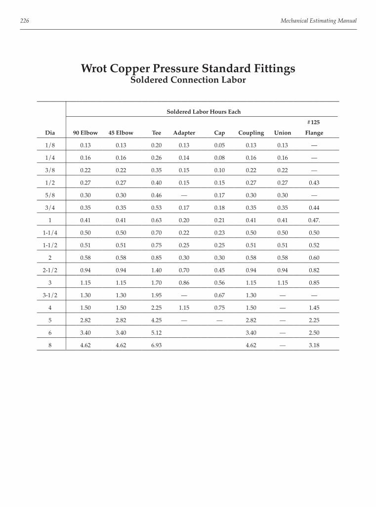
226 Mechanical Estimating Manual
Wrot Copper Pressure Standard FittingsSoldered Connection Labor
——————————————————————————————————————————————
Soldered Labor Hours Each
#125
Dia 90 Elbow 45 Elbow Tee Adapter Cap Coupling Union Flange——————————————————————————————————————————————
1/8 0.13 0.13 0.20 0.13 0.05 0.13 0.13 ———————————————————————————————————————————————
1/4 0.16 0.16 0.26 0.14 0.08 0.16 0.16 ———————————————————————————————————————————————
3/8 0.22 0.22 0.35 0.15 0.10 0.22 0.22 ———————————————————————————————————————————————
1/2 0.27 0.27 0.40 0.15 0.15 0.27 0.27 0.43——————————————————————————————————————————————
5/8 0.30 0.30 0.46 — 0.17 0.30 0.30 ———————————————————————————————————————————————
3/4 0.35 0.35 0.53 0.17 0.18 0.35 0.35 0.44——————————————————————————————————————————————
1 0.41 0.41 0.63 0.20 0.21 0.41 0.41 0.47.——————————————————————————————————————————————
1-1/4 0.50 0.50 0.70 0.22 0.23 0.50 0.50 0.50——————————————————————————————————————————————
1-1/2 0.51 0.51 0.75 0.25 0.25 0.51 0.51 0.52——————————————————————————————————————————————
2 0.58 0.58 0.85 0.30 0.30 0.58 0.58 0.60——————————————————————————————————————————————
2-1/2 0.94 0.94 1.40 0.70 0.45 0.94 0.94 0.82——————————————————————————————————————————————
3 1.15 1.15 1.70 0.86 0.56 1.15 1.15 0.85——————————————————————————————————————————————
3-1/2 1.30 1.30 1.95 — 0.67 1.30 — ———————————————————————————————————————————————
4 1.50 1.50 2.25 1.15 0.75 1.50 — 1.45——————————————————————————————————————————————
5 2.82 2.82 4.25 — — 2.82 — 2.25——————————————————————————————————————————————
6 3.40 3.40 5.12 3.40 — 2.50——————————————————————————————————————————————
8 4.62 4.62 6.93 4.62 — 3.18——————————————————————————————————————————————

Pressure Pipe and Fittings and Insulation 227
PVC Pressure Pipe, Schedule 40Threaded and Solvent Connection Labor
————————————————————
Labor Hours per Foot
Dia Thrd Solvent————————————————————
1/8 0.02 0.02————————————————————
1/4 0.02 0.02————————————————————
3/8 0.02 0.02————————————————————
1/2 0.02 0.02————————————————————
3/4 0.03 0.03————————————————————
1 0.03 0.03————————————————————
1-1/4 0.04 0.04————————————————————
1-1/2 0.04 0.04————————————————————
2 0.04 0.04————————————————————
2-1/2 0.05 0.05————————————————————
3 0.06 0.05————————————————————
3-1/2 0.07 0.05————————————————————
4 0.08 0.06————————————————————
5 0.09 0.06————————————————————
6 0.12 0.07————————————————————
8 0.15 0.09————————————————————
10 0.20 0.11————————————————————
12 0.25 0.14————————————————————
14 0.28 0.22————————————————————
16 0.32 0.25————————————————————

228 Mechanical Estimating Manual
PVC Pressure, Schedule 40 Standard FittingsSolvent Connection Labor
—————————————————————————————————————————————————
Solvent Labor Hours Each
90 D 45 D 30 D 22-1/2 D 15 D 11-1/4 D Slip
Dia Elbow Elbow Elbow Elbow Elbow Elbow Tee Wye Cross—————————————————————————————————————————————————
1/4 — — — — — — — — ——————————————————————————————————————————————————
3/8 0.10 — — — — — 0.14 — ——————————————————————————————————————————————————
1/2 0.10 0.10 — — — — 0.14 — 0.17—————————————————————————————————————————————————
3/4 0.11 0.11 — — — — 0.15 — 0.18—————————————————————————————————————————————————
1 0.12 0.12 — — — — 0.15 — 0.19—————————————————————————————————————————————————
1-1/4 0.13 0.13 — — — — 0.18 — 0.23—————————————————————————————————————————————————
1-1/2 0.14 0.14 — — — — 0.20 — 0.27—————————————————————————————————————————————————
2 0.17 0.17 0.17 0.17 0.17 0.17 0.24 — 0.32—————————————————————————————————————————————————
2-1/2 0.18 0.18 — — — — 0.27 — 0.35—————————————————————————————————————————————————
3 0.22 0.22 0.22 0.22 0.22 0.22 0.30 0.30 0.42—————————————————————————————————————————————————
4 0.30 0.28 0.28 0.28 0.28 0.28 0.40 0.40 0.55—————————————————————————————————————————————————
5 0.41 0.39 0.39 0.39 0.39 0.39 0.58 0.58 ——————————————————————————————————————————————————
6 0.52 0.50 0.50 0.50 0.50 0.50 0.75 0.75 1.14—————————————————————————————————————————————————
8 0.80 0.76 0.76 0.76 0.76 0.76 1.18 1.18 1.80—————————————————————————————————————————————————
10 1.23 1.13 1.13 1.13 1.13 1.13 1.78 1.78 2.40—————————————————————————————————————————————————
12 1.50 1.38 1.38 1.38 1.38 1.38 2.70 2.70 2.80—————————————————————————————————————————————————
14 1.91 1.75 1.75 1.75 1.75 1.75 3.40 3.40 3.50—————————————————————————————————————————————————
16 2.40 2.18 2.18 2.18 2.18 2.18 4.24 4.24 4.40—————————————————————————————————————————————————

Pressure Pipe and Fittings and Insulation 229
PVC Pressure, Schedule 40 Standard FittingsSolvent Connection Labor
—————————————————————————————————————————————————
Solvent Labor Hours Each
Adapter Adapter Slip Female Male Fitting Coupling Union Slip-on
Dia SxF SxM Cap Thrd Cap Thrd Plug Plug SxS SxS Flange—————————————————————————————————————————————————
3/8 0.16 0.16 0.06 0.06 0.02 0.02 0.10 — ——————————————————————————————————————————————————
1/2 0.18 0.18 0.06 0.06 0.02 0.02 0.10 0.10 0.25—————————————————————————————————————————————————
3/4 0.22 0.22 0.07 0.07 0.02 0.02 0.11 0.11 0.25—————————————————————————————————————————————————
1 0.27 0.27 0.07 0.07 0.02 0.02 0.11 0.11 0.27—————————————————————————————————————————————————
1-1/4 0.30 0.30 0.08 0.08 0.02 0.02 0.12 0.12 0.27—————————————————————————————————————————————————
1-1/2 0.33 0.33 0.09 0.09 0.02 0.02 0.14 0.14 0.27—————————————————————————————————————————————————
2 0.40 0.40 0.10 0.10 0.02 0.02 0.16 0.16 0.28—————————————————————————————————————————————————
2-1/2 0.62 0.62 0.11 0.11 0.03 0.03 0.18 — 0.30—————————————————————————————————————————————————
3 0.70 0.70 0.12 0.12 0.03 0.03 0.20 — 0.30—————————————————————————————————————————————————
4 1.00 1.00 0.15 0.15 0.03 0.03 0.28 — 0.60—————————————————————————————————————————————————
5 1.28 1.28 0.20 0.20 — — 0.40 — ——————————————————————————————————————————————————
6 1.55 1.55 0.26 0.26 — — 0.48 — 0.65—————————————————————————————————————————————————
8 2.52 2.52 0.40 — — — 0.75 — 0.74—————————————————————————————————————————————————
10 — — — — — — 0.95 — ——————————————————————————————————————————————————
12 — — — — — — 1.18 — ——————————————————————————————————————————————————

230 Mechanical Estimating Manual
Black BW A53 Schedule 40 PipeList Prices
————————————————————
List Price per Foot
Dia TC Pipe PE Pipe————————————————————
1/8 $1.73 $0.85————————————————————
1/4 2.08 1.15————————————————————
3/8 2.39 1.34————————————————————
1/2 1.35 0.80————————————————————
3/4 1.61 0.95————————————————————
1 2.22 1.33————————————————————
1-1/4 1.97 1.73————————————————————
1-1/2 2.34 2.05————————————————————
2 3.17 2.77————————————————————
2-1/2 5.05 4.12————————————————————
3 6.61 5.40————————————————————
3-1/2 8.11 6.19————————————————————
4 9.56 7.27————————————————————
5 — 13.63————————————————————
6 — 23.37————————————————————
8 — 34.74————————————————————
10 — 50.02————————————————————
12 — 60.26————————————————————
Supplier discounts may run 20% to 50%.
Pricing for Black BW A53 Schedule 40 Grooved Pipe same as PE Pipe.

Pressure Pipe and Fittings and Insulation 231
Black Malleable Standard Threaded FittingsList Prices
——————————————————————————————————————————————
List Prices Each
Brass
Dia 90 Elbow 45 Elbow Tee Wye Cross Cap Coupling Union——————————————————————————————————————————————
1/8 $2.17 $3.21 $3.29 — $8.01 $1.86 $2.74 $11.29——————————————————————————————————————————————
1/4 2.17 3.21 3.10 — 6.55 1.86 2.63 10.45——————————————————————————————————————————————
3/8 2.17 3.21 3.10 7.06 6.77 1.57 2.63 7.21——————————————————————————————————————————————
1/2 1.51 2.43 2.03 6.67 7.40 1.53 2.04 6.66——————————————————————————————————————————————
3/4 1.82 3.00 2.90 8.82 9.03 2.03 2.39 7.64——————————————————————————————————————————————
1 3.17 3.80 4.94 11.86 11.12 2.50 3.65 9.98——————————————————————————————————————————————
1-1/4 5.20 6.72 8.01 20.49 18.05 3.22 4.63 14.3 0——————————————————————————————————————————————
1-1/2 6.84 8.30 9.97 27.85 22.37 4.42 6.26 17.84——————————————————————————————————————————————
2 11.81 12.56 16.99 43.34 36.78 6.59 9.25 61.81——————————————————————————————————————————————
2-1/2 25.77 36.33 35.88 94.05 69.54 14.70 25.61 74.40——————————————————————————————————————————————
3 38.57 47.20 52.85 152.63 96.46 21.86 34.62 ———————————————————————————————————————————————
3-1/2 91.95 95.78 108.25 — — 43.99 — ———————————————————————————————————————————————
4 82.70 92.54 127.75 273.94 211.27 37.45 69.71 ———————————————————————————————————————————————
5 209.62 276.48 284.67 — — 79.29 — ———————————————————————————————————————————————
6 249.37 332.08 368.85 145.35 — ———————————————————————————————————————————————

232 Mechanical Estimating Manual
Black Malleable Standard Grooved FittingsList Prices
——————————————————————————————————————————————
List Prices Each
221/2 Lateral Female Std Flex #150
Dia 90 Elbow 45 Elbow Elbow Tee Wye Cross Adapter Cap Coupling Flange——————————————————————————————————————————————
3/4 $37 $30 $32 $57 $226 $141 $66 $31 $19 ———————————————————————————————————————————————
1 37 37 40 57 226 141 66 31 19 ———————————————————————————————————————————————
1-1/4 37 37 40 57 226 170 66 31 26 ———————————————————————————————————————————————
1-1/2 37 37 40 57 226 183 66 31 28 ———————————————————————————————————————————————
2 37 37 40 57 226 103 66 31 30 123——————————————————————————————————————————————
2-1/2 37 37 40 57 226 103 66 31 35 153——————————————————————————————————————————————
3 66 66 58 80 250 186 78 31 39 165——————————————————————————————————————————————
4 72 72 77 122 386 309 119 33 57 221——————————————————————————————————————————————
5 173 173 240 286 563 631 — 77 87 257——————————————————————————————————————————————
6 203 203 219 330 908 812 — 79 103 280——————————————————————————————————————————————
8 425 425 459 725 1,308 1,070 — 152 168 316——————————————————————————————————————————————
10 773 773 630 1,507 1,845 1,825 — 323 280 502——————————————————————————————————————————————
12 1,240 1,240 852 2,101 2,231 2,633 — 529 319 656——————————————————————————————————————————————
14 1,660 1,125 — 2,226 3,257 2,728 — — 387 1,507——————————————————————————————————————————————
16 2,157 1,399 — 2,515 4,068 3,569 — — 508 1,749——————————————————————————————————————————————
18 2,738 1,640 — 3,143 4,548 4,374 — — 595 2,153——————————————————————————————————————————————
20 3,609 2,155 — 4,504 6,898 6,197 — — 936 2,591——————————————————————————————————————————————
24 5,226 3,310 — 6,868 10,720 9,567 — — 997 3,315——————————————————————————————————————————————

Pressure Pipe and Fittings and Insulation 233
Carbon Steel Butt Weld Standard FittingsList Prices
——————————————————————————————————
List Prices Each
90 LR 45 LR
Din Elbow Elbow Tee Cross Cap——————————————————————————————————
1/2 $39 $37 $95 $32——————————————————————————————————
3/4 39 37 53 32——————————————————————————————————
1 20 19 53 — 32——————————————————————————————————
1-1/4 20 19 61 565 22——————————————————————————————————
1-1/2 20 19 61 565 5——————————————————————————————————
2 20 19 53 470 20——————————————————————————————————
2-1/2 27 23 67 683 20——————————————————————————————————
3 31 27 74 610 20——————————————————————————————————
3-1/2 90 84 105 — 31——————————————————————————————————
4 52 47 105 801 26——————————————————————————————————
5 111 69 190 — 45——————————————————————————————————
6 126 100 190 1,713 49——————————————————————————————————
8 237 169 348 2,551 75——————————————————————————————————
10 433 306 580 4,799 132——————————————————————————————————
12 623 433 876 5,775 164——————————————————————————————————
14 860 591 1,462 — 301——————————————————————————————————
16 1,177 807 1,767 — 354——————————————————————————————————
18 1,515 1,082 2,797 — 406——————————————————————————————————
20 2,227 1,425 4,328 — 464——————————————————————————————————
22 1,508 935 — — 320——————————————————————————————————
24 2,956 2,058 5,383 — 667——————————————————————————————————

234 Mechanical Estimating Manual
Carbon Steel Welding FlangesList Prices
——————————————————————————————————
Flanges Raised Face #150 Gasket
List Prices Each & Bolt
Dia Threaded Weldneck Slip-On Socket Blind Sets——————————————————————————————————
1/2 $54.00 $10.80 $7.63 $47.00 $43.00 $3.32——————————————————————————————————
3/4 54 50 35 47 43 3.32——————————————————————————————————
1 54 50 35 47 43 3.32——————————————————————————————————
1-1/4 54 50 35 47 43 3.32——————————————————————————————————
1-1/2 54 50 35 47 43 3.32——————————————————————————————————
2 54 54 35 47 43 5.30——————————————————————————————————
2-1/2 66 58 62 62 69 5.60——————————————————————————————————
3 66 64 49 59 55 5.87——————————————————————————————————
3-1/2 33 83 49 — 22 10.66——————————————————————————————————
4 77 76 61 77 75 10.66——————————————————————————————————
5 113 121 110 — 102 15.82——————————————————————————————————
6 127 117 99 119 117 16.58——————————————————————————————————
8 215 205 150 172 191 17.72——————————————————————————————————
10 391 329 261 — 367 36.97——————————————————————————————————
12 549 479 386 — 554 39.14——————————————————————————————————
14 — 690 512 — 946 55.45——————————————————————————————————
16 — 1,175 848 — 1291 72.85——————————————————————————————————
18 — 1,659 1,079 — 1625 102——————————————————————————————————
20 — 2,019 1,235 — 2212 136——————————————————————————————————
24 — 2,205 1,733 — 2957 182——————————————————————————————————

Pressure Pipe and Fittings and Insulation 235
Galvanized BW A53 Schedule 40 PipeList Prices
—————————————————————
List Prices Per Foot
Dia TC Pipe PE Pipe————————————————————— 1/8 $2.05 $1.78————————————————————— 1/4 1.92 1.63————————————————————— 3/8 2.13 1.81————————————————————— 1/2 1.27 1.13————————————————————— 3/4 1.53 1.36————————————————————— 1 2.11 1.87————————————————————— 1-1/4 2.75 2.41————————————————————— 1-1/2 3.29 2.87————————————————————— 2 4.42 3.86————————————————————— 2-1/2 6.91 5.93————————————————————— 3 9.05 7.77————————————————————— 3-1/2 10.98 9.02————————————————————— 4 12.93 10.62—————————————————————
Pricing not available for Pre-Grooved Pipe.
Galvanized Malleable Standard Threaded FittingsList Prices
——————————————————————————————————————————————
List Prices Each
Brass
Dia 90 Elbow 45 Elbow Tee Y Branch Cross Cap Coupling Union—————————————————————————————————————————————— 1/8 $3.18 $4.69 $4.51 — $10.52 $2.30 $3.62 $15.22—————————————————————————————————————————————— 1/4 2.92 3.98 3.82 — 10.14 2.30 3.49 13.40—————————————————————————————————————————————— 3/8 2.92 4.43 3.82 8.12 10.52 2.22 3.60 8.97—————————————————————————————————————————————— 1/2 1.92 2.97 2.43 7.29 10.01 2.09 2.75 8.36—————————————————————————————————————————————— 3/4 2.35 4.26 4.10 11.41 12.18 2.88 3.15 9.60—————————————————————————————————————————————— 1 4.35 4.82 6.49 16.28 16.83 3.56 5.20 12.56—————————————————————————————————————————————— 1-1/4 6.73 9.01 10.28 26.85 25.29 4.69 7.31 18.18—————————————————————————————————————————————— 1-1/2 8.90 10.57 12.78 36.71 29.60 6.03 8.34 22.03—————————————————————————————————————————————— 2 14.72 15.65 21.22 59.06 56.05 8.43 12.16 25.33—————————————————————————————————————————————— 2-1/2 37.74 54.45 58.52 142.00 113.34 24.49 37.24 86.13—————————————————————————————————————————————— 3 62.22 79.20 68.62 233.45 147.02 29.68 49.77 123.13—————————————————————————————————————————————— 4 109.77 132.78 162.31 385.27 308.41 65.49 105.70 ——————————————————————————————————————————————— 5 358.51 405.84 375.18 — — 133.04 — ——————————————————————————————————————————————— 6 388.00 489.33 437.67 — — 222.30 — ———————————————————————————————————————————————

236 Mechanical Estimating Manual
Copper L, K, M and ACR L-Hard TubingList Prices
——————————————————————————————————————————————— List Prices per Foot
K L M ACR L
Dia Hard Soft Hard Soft Hard Soft Dia Hard———————————————————————————————————————————————
1/4 $0.61 $0.72 $0.54 — — — ————————————————————————————————————————————————
3/8 1.05 1.15 1.80 — 0.61 0.76 3/8 $0.63———————————————————————————————————————————————
1/2 1.22 1.31 1.03 1.17 0.73 0.91 1/2 0.92———————————————————————————————————————————————
5/8 — 1.64 — — — 1.26 5/8 1.17———————————————————————————————————————————————
3/4 2.28 2.40 1.61 1.83 1.17 1.46 3/4 1.55———————————————————————————————————————————————
1 2.90 3.08 2.25 2.57 1.69 2.11 7/8 1.83———————————————————————————————————————————————
1-1/4 3.62 3.86 3.03 3.37 2.39 2.99 1-1/8 2.61———————————————————————————————————————————————
1-1/2 4.66 4.93 3.87 4.29 3.37 4.21 1-3/8 3.50———————————————————————————————————————————————
2 7.45 8.39 6.11 7.40 5.61 7.00 1-5/8 4.54———————————————————————————————————————————————
2-1/2 10.77 — 8.92 — 7.75 9.69 2-1/8 7.30———————————————————————————————————————————————
3 14.89 — 12.08 9.85 12.31 2-5/8 10.36———————————————————————————————————————————————
3-1/2 18.20 — — — — 15.15 3-1/8 14.35———————————————————————————————————————————————
4 23.21 — 19.06 — 16.65 20.81 4-1/8 23.53———————————————————————————————————————————————
5 59.65 — 53.49 — 51.19 64.00———————————————————————————————————————————————
6 85.67 — 65.23 — 63.29 79.10———————————————————————————————————————————————
8 160.40 — 120.37 112.27 140.34———————————————————————————————————————————————

Pressure Pipe and Fittings and Insulation 237
Wrot Copper Pressure Standard FittingsList Prices
——————————————————————————————————————————————
Soldered Labor Hours Each
#125
Dia 90 Elbow 45 Elbow Tee Adapter Cap Coupling Union Flange——————————————————————————————————————————————
1/8 $1.68 $2.17 $2.29 $4.51 $0.33 $0.28 $7.90 ———————————————————————————————————————————————
1/4 1.72 2.04 2.29 3.59 0.32 0.27 6.58 ———————————————————————————————————————————————
3/8 1.95 1.66 1.75 1.79 0.50 0.34 6.58 ———————————————————————————————————————————————
1/2 1.75 0.64 0.62 0.78 0.26 0.28 3.84 11.18——————————————————————————————————————————————
5/8 1.87 3.16 3.80 — 0.56 0.78 17.90 ———————————————————————————————————————————————
3/4 2.38 1.86 1.52 1.29 0.45 0.54 4.81 22.00——————————————————————————————————————————————
1 3.45 2.78 4.41 3.14 1.05 1.06 8.91 21.44——————————————————————————————————————————————
1-1/4 5.49 3.77 6.67 4.63 1.49 1.87 — 26.65——————————————————————————————————————————————
1-1/2 7.36 4.52 9.26 5.32 2.18 2.46 — 43.36——————————————————————————————————————————————
2 19.41 7.58 14.42 9.00 3.99 4.09 — 54.56——————————————————————————————————————————————
2-1/2 30.72 16.14 29.13 28.71 12.79 8.72 — 70.40——————————————————————————————————————————————
3 43.24 23.96 44.44 39.15 17.53 13.88 — 70.40——————————————————————————————————————————————
3-1/2 165 45 128 — 53 25 — ———————————————————————————————————————————————
4 113 51 107 65 33 26 — 10——————————————————————————————————————————————
5 206 198 334 — — 61 — 204——————————————————————————————————————————————
6 287 296 458 — — 95 — 224——————————————————————————————————————————————
8 1159 1059 1857 — — 329 — 561——————————————————————————————————————————————

238 Mechanical Estimating Manual
PVC Schedule 40 Pipe and Standard FittingsList Prices
——————————————————————————————————————————————
List Prices Each
Pipe 90 D 45 D 30 D 22-1/2 D 15 D 11-1/4 D Slip
Dia Per Ft Elbow Elbow Elbow Elbow Elbow Elbow Tee Wye Cross——————————————————————————————————————————————
1/8 $0.61 — — — — — — ———————————————————————————————————————————————
1/4 0.89 — — — — — — ———————————————————————————————————————————————
3/8 1.17 $0.71 — — — — — $1.15 — ———————————————————————————————————————————————
1/2 0.67 0.30 $1.96 — — — — 0.37 — $4.51——————————————————————————————————————————————
3/4 0.90 1.33 3.02 — — — — 0.42 — 7.57——————————————————————————————————————————————
1 1.32 2.41 3.63 — — — — 0.79 — 9.39——————————————————————————————————————————————
1-1/4 1.79 4.24 5.14 — — — — 1.25 — 12.44——————————————————————————————————————————————
1-1/2 2.10 4.51 6.40 — — — — 1.51 — 14.09——————————————————————————————————————————————
2 2.82 7.14 8.35 $13.38 $8.31 $13.88 $13.38 2.20 — 20.77——————————————————————————————————————————————
2-1/2 4.57 21.65 21.65 — — — — 7.25 — 43.37——————————————————————————————————————————————
3 5.82 25.91 33.66 16.87 19.93 16.87 17.91 38.02 $27.92 53.21——————————————————————————————————————————————
3-1/2 10.57 — — — — — — — — ———————————————————————————————————————————————
4 8.28 46.39 60.46 20.23 24.00 20.33 22.85 67.80 52.65 78.84——————————————————————————————————————————————
5 11.59 119.93 119.93 — — — — 163.83 — ———————————————————————————————————————————————
6 14.59 147.53 149.28 32.64 32.64 32.64 37.64 228.35 111.41 301.19——————————————————————————————————————————————
8 21.90 379.95 359.14 55.19 55.19 55.19 55.19 529.59 319.81 387.95——————————————————————————————————————————————
10 31.63 357.75 233.71 83.28 83.28 83.28 83.28 445.35 532.64 469.56——————————————————————————————————————————————
12 41.79 479.80 346.35 148.71 131.75 131.75 131.75 658.02 724.08 661.72——————————————————————————————————————————————
14 57.32 480.60 319.25 207.13 207.13 207.13 207.13 772.89 1025.83 1176.65——————————————————————————————————————————————
16 74.82 687.72 421.93 282.36 282.36 282.36 282.36 1118.81 1326.01 1491.66——————————————————————————————————————————————

Pressure Pipe and Fittings and Insulation 239
PVC Schedule 40 Standard FittingsList Prices
——————————————————————————————————————————————
List Prices Each
Adapter Adapter Slip Female Male Fitting Coupling Union Slip-on
Dia SxF SxM Cap Thrd Cap Thrd Plug Plug SxS SxS Flange——————————————————————————————————————————————
1/4 — — — — — — — — ———————————————————————————————————————————————
3/8 $1.09 $1.02 $0.76 $1.03 $0.83 $0.80 $0.53 — ———————————————————————————————————————————————
1/2 1.33 1.08 0.27 2.28 3.19 2.57 0.80 $2.91 $3.12——————————————————————————————————————————————
3/4 1.69 1.19 0.31 2.57 3.45 3.02 1.08 3.33 3.35——————————————————————————————————————————————
1 1.96 2.11 0.49 3.92 5.62 3.64 1.87 3.41 3.73——————————————————————————————————————————————
1-1/4 3.02 2.56 0.69 4.68 5.92 4.88 2.56 11.00 3.84——————————————————————————————————————————————
1-1/2 3.48 3.44 0.76 4.88 6.38 6.22 2.75 11.47 3.92——————————————————————————————————————————————
2 4.68 4.55 0.91 8.63 8.19 7.73 4.28 15.46 5.21——————————————————————————————————————————————
2-1/2 11.85 13.49 2.91 12.75 11.37 12.51 9.39 — 8.05——————————————————————————————————————————————
3 15.93 19.72 3.19 16.69 17.28 17.42 14.74 — 8.86——————————————————————————————————————————————
4 26.37 25.15 7.25 29.94 38.97 39.40 21.27 — 11.23——————————————————————————————————————————————
5 68.23 41.46 12.17 56.62 — — 38.99 — ———————————————————————————————————————————————
6 96.98 65.64 17.36 69.13 — 67.33 — 17.66——————————————————————————————————————————————
8 182.83 74.56 43.62 — — 125.68 — 28.62——————————————————————————————————————————————
10 — — — 4.31 — ———————————————————————————————————————————————
12 — 65.22 ———————————————————————————————————————————————

240 Mechanical Estimating Manual
Pipe HangersList Prices Each
——————————————————————————————————————————————
Adjustable Weld Beam
Band Swivel Roller Clevis Riser Clamp Attachment
Size Hours Price Hours Price Hours Price Hours Price Hours Price——————————————————————————————————————————————
3/4 0.60 $1.68 0.60 $1.79 0.13 $5.58 — $15.40——————————————————————————————————————————————
1 0.60 1.95 — — 0.60 1.90 0.13 5.63 — 31.85——————————————————————————————————————————————
1-1/4 0.60 2.00 0.60 $30.64 0.60 2.16 0.13 6.84 — 84.20——————————————————————————————————————————————
1-1/2 0.60 2.26 0.60 31.17 0.60 2.37 0.13 7.21 — 145.30——————————————————————————————————————————————
2 0.60 3.11 0.60 31.75 0.60 2.63 0.13 7.58 — 222.30——————————————————————————————————————————————
2-1/2 0.64 3.26 0.64 37.49 0.64 4.26 0.15 8.00 — 287.75——————————————————————————————————————————————
3 0.64 3.58 0.64 38.96 0.64 5.37 0.15 8.74 — 399.50——————————————————————————————————————————————
4 0.69 5.58 0.69 52.91 0.69 6.48 0.16 11.00 — ———————————————————————————————————————————————
5 0.69 5.90 0.69 61.71 0.69 8.95 0.16 15.22 — ———————————————————————————————————————————————
6 0.73 8.16 0.73 75.45 0.73 10.32 0.16 28.80 — ———————————————————————————————————————————————
8 0.77 12.74 0.77 115.62 0.77 17.01 0.17 29.64 — ———————————————————————————————————————————————
10 — — 0.77 135.10 0.77 32.17 0.17 44.23 — ———————————————————————————————————————————————
12 — 0.77 162.58 0.77 38.22 0.20 52.33 — ———————————————————————————————————————————————
14 — 0.86 258.62 0.86 55.65 0.20 89.98 — ———————————————————————————————————————————————
16 — — 0.86 314.43 0.86 79.29 0.22 207.39 — ———————————————————————————————————————————————
18 — — 0.97 340.86 0.97 98.46 0.22 228.34 — ———————————————————————————————————————————————
20 — — 1.07 494.65 1.07 206.91 0.22 264.36 — ———————————————————————————————————————————————
24 — — 1.18 783.54 1.18 365.50 — — — ———————————————————————————————————————————————
30 — — 1.29 1878.55 1.29 473.01 — — — ———————————————————————————————————————————————
Threaded Rods, Concrete Inserts and Anchors
——————————————————————————————————
Threaded Concrete Insert Concrete Anchor
Size Hrs/Ft Price/Ft Hrs/Ea Price/Ea Hrs/Ea Price/Ea—————————————————————————————————— 1/4 0.052 $0.33 0.080 $3.45 — ——————————————————————————————————— 3/8 0.052 0.51 0.080 3.59 — $2.05—————————————————————————————————— 1/2 0.052 0.99 0.080 3.59 — 3.75—————————————————————————————————— 5/8 0.052 1.56 0.080 3.78 — 6.95—————————————————————————————————— 3/4 0. 2.53 0.080 4.00 — 12.25—————————————————————————————————— 7/8 0.052 3.37 0.080 4.68 — ———————————————————————————————————

Pressure Pipe and Fittings and Insulation 241
Typical Hanger SpacingFeet Between Supports
——————————————————————————————— Pipe Grooved Cast Iron Plastic
Size Steel Copper Piping & No Hub (Rigid)——————————————————————————————— 1/2 8 6 6 — 3——————————————————————————————— 3/4 8 8 8 — 3——————————————————————————————— 1 8 8 8 — 3-1/2——————————————————————————————— 1-1/4 10 10 10 — 3-1/2——————————————————————————————— 1-1/2 10 10 10 5 3-1/2——————————————————————————————— 2 10 10 10 5 4——————————————————————————————— 2-1/2 11 12 12 — 4——————————————————————————————— 3 12 12 12 5 4-1/2——————————————————————————————— 4 14 12 12 5 4-1/2——————————————————————————————— 5 15 12 14 5 4-1/2——————————————————————————————— 6 16 14 14 5 5——————————————————————————————— 8 18 14 14 5 5——————————————————————————————— 10 21 — 16 5 5-1/2——————————————————————————————— 12 22 — 16 5 5-1/2——————————————————————————————— 14 25 — 18 5 ———————————————————————————————— 16 27 — 18 — ———————————————————————————————— 18 28 — 20 — ———————————————————————————————— 20 30 — 20 — ———————————————————————————————— 24 32 — 20 — ————————————————————————————————

242 Mechanical Estimating Manual
Pipe Sleeves and Cut OpeningsLabor and Material
—————————————————————————————————————————————
Material Pipe Sheet Metal Pre Fab Wood Box Cut Hole
Size Hours Price Hours Price Hours Price Hours Price Hours Price—————————————————————————————————————————————
2 0.56 $3.45 0.30 — 0.25 — 0.50 — 0.50 $1.95—————————————————————————————————————————————
3 0.56 7.07 0.30 $0.85 0.35 — 0.65 — 0.50 4.32—————————————————————————————————————————————
4 0.75 10.22 0.40 0.85 0.40 — 0.65 — 0.60 4.32—————————————————————————————————————————————
6 0.85 13.54 0.50 1.50 0.45 — 0.70 — 0.80 7.11—————————————————————————————————————————————
8 0.95 18.16 0.60 2.00 0.45 — 0.90 — 1.00 9.72—————————————————————————————————————————————
10 1.00 24.84 0.70 3.35 0.50 — 1.40 — 1.40 13.01—————————————————————————————————————————————
12 1.20 28.84 0.80 4.00 0.50 — 1.50 — 1.50 15.70—————————————————————————————————————————————
14 1.30 — 0.80 4.75 0.60 — 1.70 — 2.40 19.08—————————————————————————————————————————————
16 1.50 0.90 5.20 0.65 — 1.90 — 3.00 22.06—————————————————————————————————————————————
18 1.60 1.00 5.90 0.70 — 2.00 — 3.50 24.72—————————————————————————————————————————————
Hanger Rod Sizes and Weights
—————————————————————— Pipe Sizes Rod Size Weight Lbs/Ft
—————————————————————— 3/4-2 3/8 0.376
—————————————————————— 2-1/2 - 3-1/2 1/2 0.668
—————————————————————— 4-5 5/8 1.045
—————————————————————— 6 3/4 1.500
—————————————————————— 8-12 7/8 2.045
—————————————————————— 14-16 1 2.670
—————————————————————— 18 1-1/8 3.380
—————————————————————— 20 1-1/4 4.175
—————————————————————— 24 1-1/2 6.000
—————————————————————— 30 1-7/8 9.338
——————————————————————

Pressure Pipe and Fittings and Insulation 243
Fiberglass Blanket ASJ 3Lb InsulationLabor
———————————————————————————————
Labor Hours per Foot
Insulation Thickness
Dia 1/2” 1” 1-1/2” 2”———————————————————————————————
1/8 — — — ————————————————————————————————
1/4 — — — ————————————————————————————————
3/8 — — — ————————————————————————————————
1/2 0.05 0.06 0.06 0.06———————————————————————————————
5/8 0.05 0.06 0.06 0.06———————————————————————————————
3/4 0.06 0.06 0.06 0.07———————————————————————————————
7/8 0.06 0.06 0.07 0.07———————————————————————————————
1 0.06 0.06 0.07 0.07———————————————————————————————
1-1/4 0.07 0.07 0.07 0.08———————————————————————————————
1-1/2 0.07 0.07 0.08 0.08———————————————————————————————
2 0.07 0.08 0.08 0.09———————————————————————————————
2-1/2 0.07 0.08 0.09 0.09———————————————————————————————
3 0.08 0.08 0.09 0.10———————————————————————————————
3-1/2 0.08 0.09 0.10 0.10———————————————————————————————
4 0.09 0.09 0.10 0.11———————————————————————————————
5 0.10 0.10 0.11 0.12———————————————————————————————
6 0.11 0.12 0.13 0.15———————————————————————————————
8 0.12 0.15 0.17 0.19———————————————————————————————
10 — 0.17 0.19 0.21———————————————————————————————
12 — 0.19 0.20 0.23———————————————————————————————
14 — 0.19 0.22 0.25———————————————————————————————
16 — 0.21 0.24 0.27———————————————————————————————
18 — 0.21 0.25 0.30———————————————————————————————
20 — 0.25 0.28 0.34———————————————————————————————
24 — 0.25 0.30 0.38———————————————————————————————
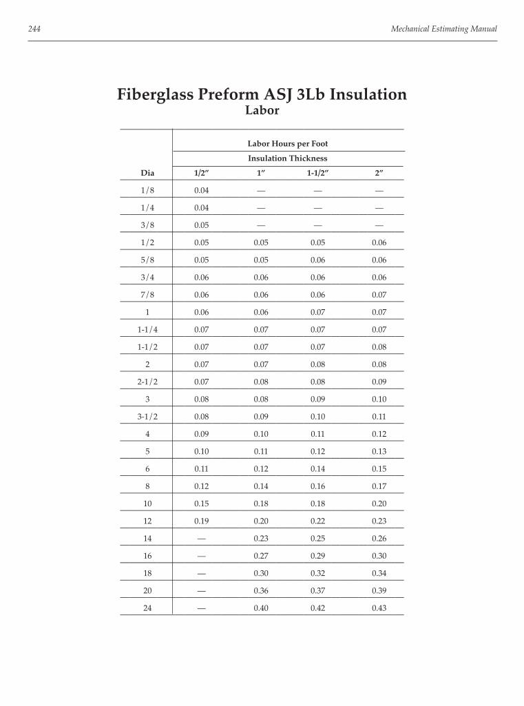
244 Mechanical Estimating Manual
Fiberglass Preform ASJ 3Lb InsulationLabor
———————————————————————————————
Labor Hours per Foot
Insulation Thickness
Dia 1/2” 1” 1-1/2” 2”———————————————————————————————
1/8 0.04 — — ————————————————————————————————
1/4 0.04 — — ————————————————————————————————
3/8 0.05 — — ————————————————————————————————
1/2 0.05 0.05 0.05 0.06———————————————————————————————
5/8 0.05 0.05 0.06 0.06———————————————————————————————
3/4 0.06 0.06 0.06 0.06———————————————————————————————
7/8 0.06 0.06 0.06 0.07———————————————————————————————
1 0.06 0.06 0.07 0.07———————————————————————————————
1-1/4 0.07 0.07 0.07 0.07———————————————————————————————
1-1/2 0.07 0.07 0.07 0.08———————————————————————————————
2 0.07 0.07 0.08 0.08———————————————————————————————
2-1/2 0.07 0.08 0.08 0.09———————————————————————————————
3 0.08 0.08 0.09 0.10———————————————————————————————
3-1/2 0.08 0.09 0.10 0.11———————————————————————————————
4 0.09 0.10 0.11 0.12———————————————————————————————
5 0.10 0.11 0.12 0.13———————————————————————————————
6 0.11 0.12 0.14 0.15———————————————————————————————
8 0.12 0.14 0.16 0.17———————————————————————————————
10 0.15 0.18 0.18 0.20———————————————————————————————
12 0.19 0.20 0.22 0.23———————————————————————————————
14 — 0.23 0.25 0.26———————————————————————————————
16 — 0.27 0.29 0.30———————————————————————————————
18 — 0.30 0.32 0.34———————————————————————————————
20 — 0.36 0.37 0.39———————————————————————————————
24 — 0.40 0.42 0.43———————————————————————————————

Pressure Pipe and Fittings and Insulation 245
Foam Plastic InsulationLabor
———————————————————————————————
Labor Hours per Foot
Insulation Thickness
Dia 3/8” 1/2” 3/4” 1”———————————————————————————————
1/8 0.05 0.06 0.06 0.07———————————————————————————————
1/4 0.05 0.06 0.06 0.07———————————————————————————————
3/8 0.05 0.06 0.06 0.07———————————————————————————————
1/2 0.05 0.06 0.07 0.07———————————————————————————————
5/8 0.05 0.06 0.07 0.07———————————————————————————————
3/4 0.06 0.06 0.07 0.07———————————————————————————————
7/8 0.06 0.06 0.07 0.07———————————————————————————————
1 0.06 0.06 0.07 0.07———————————————————————————————
1-1/4 0.06 0.06 0.07 0.08———————————————————————————————
1-1/2 0.06 0.06 0.07 0.08———————————————————————————————
2 0.06 0.06 0.07 0.08———————————————————————————————
2-1/2 0.06 0.07 0.07 0.08———————————————————————————————
3 0.06 0.07 0.08 0.09———————————————————————————————
3-1/2 0.07 0.07 0.08 ————————————————————————————————
4 0.07 0.07 0.08———————————————————————————————

246 Mechanical Estimating Manual
Calcium Silicate InsulationLabor
———————————————————————————————
Labor Hours per Foot
Insulation Thickness
Dia 1” 1-1/2” 2” 3”———————————————————————————————
1/2 0.08 0.08 0.09 0.12———————————————————————————————
5/8 0.08 0.08 0.09 0.12———————————————————————————————
3/4 0.08 0.09 0.09 ————————————————————————————————
7/8 0.08 0.09 0.09 ————————————————————————————————
1 0.08 0.09 0.10 0.13———————————————————————————————
1-1/4 0.08 0.09 0.10 0.13———————————————————————————————
1-1/2 0.08 0.09 0.10 0.13———————————————————————————————
2 0.09 0.09 0.10 0.14———————————————————————————————
2-1/2 0.09 0.10 0.11 0.14———————————————————————————————
3 0.09 0.10 0.11 0.15———————————————————————————————
3-1/2 0.10 0.10 0.11 0.15———————————————————————————————
4 0.10 0.10 0.12 0.16———————————————————————————————
5 0.10 0.11 0.12 0.16———————————————————————————————
6 0.11 0.11 0.13 0.17———————————————————————————————
8 — 0.14 0.14 0.18———————————————————————————————
10 — 0.15 0.16 0.19———————————————————————————————
12 — 0.16 0.17 0.22———————————————————————————————
14 — 0.17 0.18 0.23———————————————————————————————
16 — 0.18 0.19 0.25———————————————————————————————
18 — 0.20 0.20 0.27———————————————————————————————
20 — — 0.23 0.30———————————————————————————————
22 — 0.25 0.34———————————————————————————————
24 — 0.27 0.37———————————————————————————————

Pressure Pipe and Fittings and Insulation 247
Rigid Eurethane InsulationLabor
———————————————————————————————
Labor Hours per Foot
Insulation Thickness
Dia 1/2” 1” 1-1/2” 2”———————————————————————————————
1/8 0.04 0.05 0.05 0.05———————————————————————————————
1/4 0.04 0.05 0.05 0.05———————————————————————————————
3/8 0.05 0.05 0.05 0.06———————————————————————————————
1/2 0.05 0.05 0.06 0.06———————————————————————————————
5/8 0.06 0.06 0.06 0.06———————————————————————————————
3/4 0.06 0.06 0.06 0.06———————————————————————————————
7/8 0.06 0.06 0.06 0.06———————————————————————————————
1 0.06 0.06 0.06 0.06———————————————————————————————
1-1/4 0.06 0.06 0.06 0.07———————————————————————————————
1-1/2 0.06 0.06 0.07 0.07———————————————————————————————
2 0.06 0.07 0.07 0.07———————————————————————————————
2-1/2 0.07 0.07 0.07 0.08———————————————————————————————
3 0.08 0.07 0.08 0.09———————————————————————————————
3-1/2 0.08 0.09 0.10 0.11———————————————————————————————
4 0.09 0.10 0.11 0.12———————————————————————————————
5 0.10 0.11 0.12 0.13———————————————————————————————
6 0.11 0.12 0.13 0.14———————————————————————————————
8 0.14 0.15 0.16 0.17———————————————————————————————
10 0.17 0.19 0.20 0.19———————————————————————————————
12 0.20 0.21 0.22 0.24———————————————————————————————

248 Mechanical Estimating Manual
Foam Rubber Tubing InsulationLabor
—————————————————————————
Labor Hours per Foot
Insulation Thickness
Dia 3/8” 1/2” 3/4”—————————————————————————
1/4 0.06 0.07 0.07—————————————————————————
3/8 0.06 0.07 0.07—————————————————————————
1/2 0.06 0.07 0.07—————————————————————————
5/8 0.06 0.07 0.07—————————————————————————
3/4 0.06 0.07 0.07—————————————————————————
7/8 0.06 0.07 0.08—————————————————————————
1 0.07 0.08 0.08—————————————————————————
1-1/4 0.07 0.08 0.08—————————————————————————
1-1/2 0.07 0.08 0.08—————————————————————————
2 0.07 0.08 0.08—————————————————————————
2-1/2 0.07 0.08 0.09—————————————————————————
3 0.08 0.09 0.09—————————————————————————
3-1/2 0.08 0.09 0.09—————————————————————————
4 0.08 0.09 0.09—————————————————————————
5 0.08 0.09 0.10—————————————————————————
6 0.08 0.10 0.10—————————————————————————

Pressure Pipe and Fittings and Insulation 249
Fiberglass Preform ASJ 3Lb InsulationInstalled Prices with Overhead and Profi t
———————————————————————————————
Labor Hours per Foot
Insulation Thickness
Dia 1/2” 1” 1-1/2” 2”———————————————————————————————
1/2 $3.04 $3.29 $4.47 $5.77———————————————————————————————
3/4 3.23 3.54 4.65 6.00———————————————————————————————
1 3.38 3.69 4.89 6.38———————————————————————————————
1-1/4 3.59 3.94 5.21 6.75———————————————————————————————
1-1/2 3.69 4.06 5.35 6.93———————————————————————————————
2 3.89 4.31 5.72 7.26———————————————————————————————
2-1/2 4.20 4.64 6.14 7.77———————————————————————————————
3 4.52 5.03 6.42 8.33———————————————————————————————
3-1/2 4.79 5.40 6.93 8.93———————————————————————————————
4 5.54 6.19 7.58 9.86———————————————————————————————
5 6.05 6.89 8.33 10.89———————————————————————————————
6 7.07 7.68 9.27 12.00———————————————————————————————
8 — 9.91 11.40 14.88———————————————————————————————
10 — 11.30 13.49 17.44———————————————————————————————
12 — 12.79 14.56 18.60———————————————————————————————
14 — 13.77 16.23 21.39———————————————————————————————
16 — 16.05 17.86 23.25———————————————————————————————
18 — 16.65 19.53 25.11———————————————————————————————
20 — 18.60 21.39 27.90———————————————————————————————
24 — 21.39 24.18 31.62———————————————————————————————

250 Mechanical Estimating Manual
Foam Plastic InsulationInstalled Prices with Overhead and Profi t
———————————————————————————————
Labor Hours per Foot
Insulation Thickness
Dia 3/8” 1/2” 3/4” 1”———————————————————————————————
1/8 $2.41 $2.71 $3.02 ————————————————————————————————
1/4 2.44 2.72 3.04 $3.46———————————————————————————————
3/8 2.46 2.73 3.11 3.55———————————————————————————————
1/2 2.55 2.78 3.26 3.82———————————————————————————————
3/4 2.64 2.87 3.37 3.94———————————————————————————————
1 2.74 2.99 3.57 4.34———————————————————————————————
1-1/4 2.85 3.13 3.85 4.53———————————————————————————————
1-1/2 2.90 3.26 3.95 4.58———————————————————————————————
2 3.04 3.44 4.42 5.03———————————————————————————————
2-1/2 3.27 3.70 4.74 5.30———————————————————————————————
3 3.39 4.01 5.07 5.58———————————————————————————————
4 — 4.49 5.77 ————————————————————————————————

Pressure Pipe and Fittings and Insulation 251
Calcium Silicate InsulationInstalled Prices with Overhead and Profi t
———————————————————————————————
Labor Hours per Foot
Insulation Thickness
Dia 1/2” 1” 2” 3”———————————————————————————————
1/2 $5.21 $5.82 $7.49 ————————————————————————————————
3/4 5.21 5.86 7.63 ————————————————————————————————
1 5.12 6.05 7.82 ————————————————————————————————
1-1/4 5.26 6.38 8.28 $10.98———————————————————————————————
1-1/2 5.26 6.51 8.47 11.30———————————————————————————————
2 5.77 6.89 8.84 11.96———————————————————————————————
2-1/2 5.96 7.21 9.77 12.79———————————————————————————————
3 6.33 7.49 9.72 12.84———————————————————————————————
3-1/2 7.03 — — ————————————————————————————————
4 7.49 8.47 10.79 15.35———————————————————————————————
5 7.96 9.07 11.86 ————————————————————————————————
6 5.82 9.63 12.98 17.72———————————————————————————————
8 — 11.68 17.44 20.46———————————————————————————————
10 — 14.28 20.46 25.11———————————————————————————————
12 — 17.17 23.25 26.04———————————————————————————————
14 — 21.39 25.11 29.76———————————————————————————————
16 — 24.18 26.97 32.55———————————————————————————————
18 — 26.04 29.76 35.34———————————————————————————————

252 Mechanical Estimating Manual
Foam Rubber Tubing InsulationInstalled Prices with Overhead and Profi t
—————————————————————————
Labor Hours per Foot
Insulation Thickness
Dia 3/8” 1/2” 3/4”—————————————————————————
1/4 $2.72 $3.67 $3.85—————————————————————————
3/8 2.75 3.72 3.93—————————————————————————
1/2 2.89 3.79 4.07—————————————————————————
3/4 2.94 3.85 4.23—————————————————————————
1 3.10 3.93 4.39—————————————————————————
1-1/4 3.19 4.05 4.79—————————————————————————
1-1/2 3.29 4.18 4.93—————————————————————————
2 3.69 4.39 5.26—————————————————————————
2-1/2 4.17 4.65 5.86—————————————————————————
3 4.30 5.21 6.42—————————————————————————
3-1/2 4.79 5.26 6.70—————————————————————————
4 — 5.63 7.12—————————————————————————
5 — 6.51 7.82—————————————————————————
6 — — 10.56—————————————————————————

253
Chapter 18
Valves and Specialties
This chapter covers labor and price tables for valves and specialties in pressure type piping systems as follows:
Standard Valves:• Bronze Valves, Threaded and Soldered, 125#, 150#,
300#• Iron Valves, Flanged and Welded, 125#, 150#, 250#• Ductile Iron Valves, Flanged and Grooved, #200• Plastic PVC Valves, Socket, Threaded and Flanged• Carbon Steel Valves, Threaded and Welded, #250,
#1000
Specialty Valves:• Strainers • Control Valves• Steam Traps • Pressure Valves• Gas Valves • Temperature Control Valves• Balancing Valves • Gas Valves
Specialties:• Hot Water • Refrigeration• Chilled Water • Steam
Units All diameters are in inches. Flanges and hangers are covered in chapter 17.
Labor The labor productivity rates in the tables are what the average mechanic under average conditions can erect on lower fl oors of construction projects. However, they may require the application of labor correction factors for variable conditions such as upper fl oors, higher piping runs, congested spaces, etc. The labor in the tables are in hours per piece and hours per foot for pipe.
Pricing and Discounts The pricing in the tables are based on the typical manufacturers list prices and the contractor’s supplier discounts must be applied. Appropriate price discounts can range from roughly 10 percent to 80 percent dependent on the following:
• Supplier discount structure• Who manufacturer is• Size of batch involved• Availability• Shipping distance, costs
Not All List Prices Are Publicly Available Where there are no prices listed in tables, they are not usually publicly available from the manufacturer. If there is neither labor nor prices listed for a particular di-ameter in the tables, the particular item may not be avail-able or it may not be a commonly used item.
Caution With List Prices Pricing can sometimes vary signifi cantly because of changes in commodity material pricing such as copper, etc. Periodic checks of current list prices should be made. If in doubt about your discounts from list prices, check with your supplier as to what they are for the various categories of items - or request a quotation.
Automatic Updating Available in Wendes Computer System Automatic updating of list pricing is available in the Wendes Computerized Piping Estimating System. Call (847) 818-8371 for more information.

254 Mechanical Estimating Manual
Bronze #125 ValvesThreaded and Soldered Connections
—————————————————————————
Threaded Soldered
Diameter Labor Price Labor Price————————————————————————— Angle Valve————————————————————————— 1/4 0.37 $33.40 0.29 $22.80 3/8 0.37 33.40 0.29 22.80 1/2 0.37 33.40 0.29 22.80 3/4 0.50 45.60 0.39 31.30 1 0.61 59.60 0.48 41.00 1-1/4 0.71 88.60 0.54 — 1-1/2 0.78 103.40 0.58 153.00 2 0.96 155.90 0.69 222.00 2-1/2 1.53 279.90 1.11 — 3 1.88 592.20 1.38 ——————————————————————————
Ball Valve————————————————————————— 1/2 0.36 $5.50 0.34 $5.50 3/4 0.50 7.70 0.45 7.70 1 0.61 12.65 0.55 12.65 1-1/4 0.71 22.10 0.60 22.10 1-1/2 0.79 27.80 0.65 27.80 2 0.95 35.10 0.73 35.10—————————————————————————
Check Valve————————————————————————— 3/8 0.37 $14.80 0.29 $14.80 1/2 0.37 15.80 0.29 15.80 3/4 0.50 19.50 0.39 19.50 1 0.61 25.90 0.48 25.90 1-1/4 0.71 32.70 0.54 32.70 1-1/2 0.78 43.30 0.58 43.30 2 0.96 60.00 0.69 60.00 2-1/2 1.53 — — — 3 1.88 — — ——————————————————————————
Bronze #125 ValvesThreaded and Soldered Connections
—————————————————————————
Threaded Soldered
Diameter Labor Price Labor Price————————————————————————— Gate Valve————————————————————————— 1/4 0.36 $24.00 0.29 — 3/8 0.36 24.53 0.29 $22.00 1/2 0.36 21.16 0.29 21.37 3/4 0.50 26.11 0.39 24.63 1 0.61 33.26 0.46 34.84 1-1/4 0.73 49.37 0.52 52.53 1-1/2 0.81 57.68 0.57 59.37 2 0.97 75.68 0.66 83.37 2-1/2 1.56 198.11 1.05 194.95 3 1.89 241.89 1.29 274.74—————————————————————————
Globe Valve————————————————————————— 1/8 0.38 $33.40 — — 1/4 0.38 33.40 — — 3/8 0.38 35.26 0.29 $36.00 1/2 0.38 35.26 0.29 36.00 3/4 0.50 45.68 0.39 45.89 1 0.62 62.11 0.48 62.63 1-1/4 0.73 82.32 0.54 81.37 1-1/2 0.82 106.95 0.58 106.00 2 1.02 162.00 0.69 160.42 2-1/2 1.62 370.00 1.11 373.00 3 1.99 527.00 1.38 532.00—————————————————————————

Valves and Specialties 255
Bronze #150 ValvesThreaded and Soldered Connections
—————————————————————————
Threaded Soldered
Diameter Labor Price Labor Price————————————————————————— Angle Valve————————————————————————— 1/8 0.37 $44.70 — — 1/4 0.37 54.46 — — 3/8 0.37 54.46 — — 1/2 0.37 54.46 — — 3/4 0.50 74.01 — — 1 0.61 106.93 — — 1-1/4 0.71 139.51 — — 1-1/2 0.78 186.39 — — 2 0.96 292.51 — — 2-1/2 1.53 478.30 — — 3 1.88 750.00 — ——————————————————————————
Ball Valve————————————————————————— 1/4 0.36 $9.40 0.34 $9.40 3/8 0.36 9.40 0.34 9.40 1/2 0.36 9.40 0.34 9.40 3/4 0.50 15.30 0.45 15.30 1 0.61 19.40 0.55 19.40 1-1/4 0.71 32.60 0.60 32.60 1-1/2 0.79 41.60 0.65 41.60 2 0.95 52.00 0.73 52.00 2-1/2 1.61 245.00 1.27 245.00 3 1.90 273.00 1.50 273.00—————————————————————————
Check Valve————————————————————————— 1/4 0.37 $40.10 0.29 $41.20 3/8 0.37 40.10 0.29 41.20 1/2 0.37 40.10 0.29 41.20 3/4 0.50 47.50 0.39 49.70 1 0.61 64.00 0.48 68.00 1-1/4 0.71 86.00 0.54 88.00 1-1/2 0.78 116.00 0.58 117.00 2 0.96 174.00 0.69 171.00 2-1/2 1.53 250.00 1.11 272.00 3 1.88 371.00 1.38 404.00—————————————————————————
Bronze #150 ValvesThreaded and Soldered Connections
—————————————————————————
Threaded Soldered
Diameter Labor Price Labor Price————————————————————————— Gate Valve————————————————————————— 1/4 0.36 $41.00 — — 3/8 0.36 41,00 0.29 $49.60 1/2 0.36 39.50 0.29 47.50 3/4 0.50 43.50 0.39 58.00 1 0.61 53.10 0.46 76.00 1-1/4 0.73 73.90 0.52 108.00 1-1/2 0.81 92.50 0.57 131.00 2 0.97 125.40 0.66 189.00 2-1/2 1.56 337.60 1.05 389.00 3 1.89 464.50 1.29 530.00 3-1/2 2.29 944.00 — — 4 2.29 1145.00 1.85 1114.00 5 — — 2.22 — 6 — — 2.50 ——————————————————————————
Globe Valve————————————————————————— 1/4 0.38 $43.37 0.29 $53.00 3/8 0.38 43.37 0.29 $53.00 1/2 0.38 43.37 0.29 52.00 3/4 0.50 58.63 0.39 69.00 1 0.62 91.26 0.48 98.00 1-1/4 0.73 145.05 0.54 153.00 1-1/2 0.82 173.05 0.58 186.00 2 1.02 261.37 0.69 275.00 2-1/2 1.62 535.58 1.11 538.00 3 1.99 762.00 1.38 693.00—————————————————————————

256 Mechanical Estimating Manual
Bronze #300 ValvesThreaded and Soldered Connections
—————————————————————————
Threaded Soldered
Diameter Labor Price Labor Price————————————————————————— Angle Valve————————————————————————— 1/4 0.37 $83.79 — — 3/8 0.37 83.79 — — 1/2 0.37 63.68 — — 3/4 0.50 101.37 — — 1 0.61 170.42 — — 1-1/4 0.71 259.16 — — 1-1/2 0.78 259.16 — — 2 0.96 323.47 — — 2-1/2 1.53 773.00 — — 3 1.88 1062.00 — ——————————————————————————
Ball Valve————————————————————————— 1/2 0.36 7.50 — — 3/4 0.50 9.26 — — 1 0.61 13.61 — — 1-1/4 0.71 23.15 — — 1-1/2 0.79 29.99 — — 2 0.95 42.72 — ——————————————————————————
Check Valve————————————————————————— 1/4 — — 0.29 — 3/8 0.37 $41.70 0.29 — 1/2 0.37 41.70 0.29 — 3/4 0.50 52.00 0.39 — 1 0.61 70.00 0.48 — 1-1/4 0.71 88.00 0.54 — 1-1/2 0.78 119.00 0.58 — 2 0.96 177.00 0.69 — 2-1/2 — — 1.11 — 3 — — 1.38 ——————————————————————————
Bronze #300 ValvesThreaded and Soldered Connections
—————————————————————————
Threaded Soldered
Diameter Labor Price Labor Price————————————————————————— Gate Valve————————————————————————— 1/4 0.38 $67.00 — — 3/8 0.38 67.00 — — 1/2 0.38 65.00 — — 3/4 0.52 169.80 — — 1 0.65 191.90 — — 1-1/4 0.76 225.00 — — 1-1/2 0.86 235.10 — — 2 1.11 345.50 — ——————————————————————————
Globe Valve————————————————————————— 1/4 0.37 $83.88 — — 3/8 0.37 85.88 — — 1/2 0.37 89.24 — — 3/4 0.52 127.07 — — 1 0.70 180.58 — — 1-1/4 0.76 255.38 — — 1-1/2 0.86 321.74 — — 2 1.04 429.23 — — 2-1/2 1.76 649.00 — — 3 2.18 1030.00 — ——————————————————————————
Iron #125 ValvesThreaded and Flanged Connections
—————————————————————————
Threaded Flanged
Diameter Labor Price Labor Price————————————————————————— Angle Valve————————————————————————— 2 — — 0.85 $792.00 2-1/2 — — 0.94 850.00 3 — — 1.05 924.00 4 — — 1.90 1315.00 5 — — 2.39 2568.00 6 — — 2.75 2568.00 8 — — 3.93 4595.00—————————————————————————
Check Valve, Swing————————————————————————— 2 0.96 — 0.85 $205.70 2-1/2 1.53 — 0.94 263.40 3 1.88 — 1.05 2.84 4 2.01 — 1.90 447.40 5 2.53 — 2.39 774.80 6 2.81 — 2.75 762.20 8 — — 3.93 1434.10 10 — — 5.47 2447.00 12 — — 6.42 3804.50 14 — — 8.76 10180.50 16 — — 9.61 13042.40 18 — — 10.34 17355.90—————————————————————————

Valves and Specialties 257
Iron #150 ValvesThreaded and Flanged Connections
—————————————————————————
Threaded Flanged
Diameter Labor Price Labor Price————————————————————————— Butterfl y Valve, Wafer————————————————————————— 2 — — 0.66 $130.75 2-1/2 — — 0.66 105.05 3 — — 0.66 129.63 4 — — 1.31 155.53 5 — — 1.52 210.09 6 — — 1.52 421.30 8 — — 1.61 — 10 — — 2.56 — 12 — — 2.76 — 14 — — 4.02 — 16 — — 5.14 — 18 — — 6.08 — 20 — — 7.31 — 24 — — 8.92—————————————————————————
Iron #250 ValvesThreaded and Flanged Connections
—————————————————————————
Threaded Flanged
Diameter Labor Price Labor Price————————————————————————— Angle Valve————————————————————————— 2-1/2 — — 1.88 $1,976.00 3 — — 2.08 2254.00 4 — — 2.65 2833.00 6 — — 4.24 4809.00 8 — — 5.82 8404.00—————————————————————————
Check Valve, Wafer————————————————————————— 2 — — 1.03 $226.00 2-1/2 — — 1.29 270.00 3 — — 1.35 305.00 4 — — 1.37 409.00 5 — — 1.41 552.00 6 — — 2.11 705.00 8 — — 2.44 1415.00 10 — — 3.78 2092.00—————————————————————————
Iron #125 ValvesThreaded and Flanged Connections
—————————————————————————
Threaded Flanged
Diameter Labor Price Labor Price————————————————————————— Gate Valve, Iron————————————————————————— 2 0.97 $339.00 0.99 $344.60 2-1/2 1.56 377.00 1.11 385.20 3 1.89 411.00 1.21 385.20 4 2.26 570.00 2.26 568.20 5 — — 2.79 939.00 6 — — 3.04 953.00 8 — — 4.17 1756.10 10 — — 5.78 3644.80 12 — — 6.62 5278.30—————————————————————————
Globe Valve, Bronze Mounted————————————————————————— 2 — — 0.94 $585.20 2-1/2 — — 1.11 619.50 3 — — 1.25 716.30 4 — — 2.20 1024.80 5 — — 2.83 1868.80 6 — — 3.18 1834.60 8 — — 4.43 3657.10 10 — — 6.22 6425.70—————————————————————————
Iron #150 ValvesThreaded and Flanged Connections
—————————————————————————
Threaded Flanged
Diameter Labor Price Labor Price————————————————————————— Gate Valve, RS U-Bolt Bonnet————————————————————————— 1/4 0.36 $78.00 — — 3/8 0.36 74.00 — — 1/2 0.36 70.00 — — 3/4 0.50 70.00 — — 1 0.61 70.00 — — 1-1/4 0.73 92.00 — — 1-1/2 0.81 98.00 — — 2 0.97 142.00 0.99 — 2-1/2 1.56 213.00 1.11 — 3 1.89 277.00 1.21 — 4 2.29 642.00 2.26 ——————————————————————————
Check Valve, Wafer————————————————————————— 1-1/2 — — 0.64 $131.00 2 — — 0.64 175.00 2-1/2 — — 0.64 192.00 3 — — 0.64 206.00 4 — — 1.29 263.00 5 — — 1.52 344.00 6 — — 1.52 460.00 8 — — 1.76 822.00 10 — — 2.93 1422.00 12 — — 3.34 2715.00—————————————————————————

258 Mechanical Estimating Manual
Iron #250 ValvesThreaded and Flanged Connections
—————————————————————————
Threaded Flanged
Diameter Labor Price Labor Price————————————————————————— Gate Valve, OS & Y————————————————————————— 2 — — 1.56 $672.60 2-1/2 — — 2.02 820.90 3 — — 2.53 930.60 4 — — 3.29 1349.60 5 — — 4.10 2284.20 6 — — 5.41 2284.20 8 — — 6.41 3959.60 10 — — 8.54 5922.70 12 — — 21.14 9243.10—————————————————————————
Globe Valve————————————————————————— 2 — — 1.42 $734.00 2-1/2 — — 2.06 1057.00 3 — — 2.29 1095.00 4 — — 2.89 1601.00 6 — — 5.03 2877.00 8 — — 5.99 4880.00—————————————————————————
Ductile Iron #200 ValvesFlanged and Grooved Connections
—————————————————————————
Lug Style Wafer Style
Diameter Labor Price Labor Price————————————————————————— Butterfl y Valve, Flanged————————————————————————— 2 0.66 $100.00 0.10 $84.00 2-1/2 0.66 102.00 0.10 $89.00 3 0.66 114.00 0.14 96.00 4 1.32 143.00 0.20 120.00 5 1.53 207.00 0.23 171.00 6 1.61 244.00 0.31 209.00 8 1.77 338.00 0.48 314.00 10 2.69 475.00 0.71 434.00 12 3.00 751.00 1.24 668.00—————————————————————————
Grooved Connection—————————————————————————
Man Handle Gear Handle
Diameter Labor Price Labor Price————————————————————————— Butterfl y Valve, Grooved————————————————————————— 1-1/2 — — 0.66 $745.30 2 0.63 $312.75 0.76 661.85 2-1/2 0.62 396.60 0.76 745.40 3 0.72 448.50 0.87 764.95 4 1.05 493.85 1.05 856.10 5 1.52 942.35 1.52 1291.70 6 1.83 1081.70 1.83 1371.15—————————————————————————
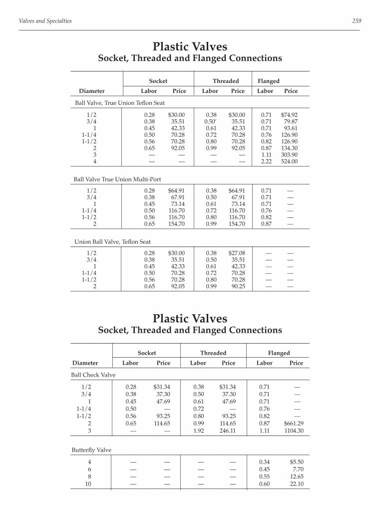
Valves and Specialties 259
Plastic ValvesSocket, Threaded and Flanged Connections
————————————————————————————————————
Socket Threaded Flanged
Diameter Labor Price Labor Price Labor Price————————————————————————————————————
Ball Valve, True Union Tefl on Seat————————————————————————————————————
1/2 0.28 $30.00 0.38 $30.00 0.71 $74.92 3/4 0.38 35.51 0.50’ 35.51 0.71 79.87 1 0.45 42.33 0.61 42.33 0.71 93.61 1-1/4 0.50 70.28 0.72 70.28 0.76 126.90 1-1/2 0.56 70.28 0.80 70.28 0.82 126.90 2 0.65 92.05 0.99 92.05 0.87 134.30 3 — — — — 1.11 303.90 4 — — — — 2.22 524.00
————————————————————————————————————
Ball Valve True Union Multi-Port————————————————————————————————————
1/2 0.28 $64.91 0.38 $64.91 0.71 — 3/4 0.38 67.91 0.50 67.91 0.71 — 1 0.45 73.14 0.61 73.14 0.71 — 1-1/4 0.50 116.70 0.72 116.70 0.76 — 1-1/2 0.56 116.70 0.80 116.70 0.82 — 2 0.65 154.70 0.99 154.70 0.87 —
————————————————————————————————————
Union Ball Valve, Tefl on Seat————————————————————————————————————
1/2 0.28 $30.00 0.38 $27.08 — — 3/4 0.38 35.51 0.50 35.51 — — 1 0.45 42.33 0.61 42.33 — — 1-1/4 0.50 70.28 0.72 70.28 — — 1-1/2 0.56 70.28 0.80 70.28 — — 2 0.65 92.05 0.99 90.25 — —
————————————————————————————————————
Plastic ValvesSocket, Threaded and Flanged Connections
————————————————————————————————————
Socket Threaded Flanged
Diameter Labor Price Labor Price Labor Price————————————————————————————————————
Ball Check Valve————————————————————————————————————
1/2 0.28 $31.34 0.38 $31.34 0.71 — 3/4 0.38 37.30 0.50 37.30 0.71 — 1 0.45 47.69 0.61 47.69 0.71 — 1-1/4 0.50 — 0.72 — 0.76 — 1-1/2 0.56 93.25 0.80 93.25 0.82 — 2 0.65 114.65 0.99 114.65 0.87 $661.29 3 — — 1.92 246.11 1.11 1104.30
————————————————————————————————————
Butterfl y Valve————————————————————————————————————
4 — — — — 0.34 $5.50 6 — — — — 0.45 7.70 8 — — — — 0.55 12.65 10 — — — — 0.60 22.10
————————————————————————————————————

260 Mechanical Estimating Manual
Cast Iron #1000 ValvesThreaded and Welded Connections
—————————————————————————
Threaded Welded
Diameter Labor Price Labor Price————————————————————————— Ball Valve, 3 pc Full Port————————————————————————— 1/4 0.36 $40.47 — — 3/8 0.36 40.47 — — 1/2 0.36 47.15 0.71 $45.33 3/4 0.49 58.54 0.85 57.26 1 0.61 70.92 1.08 71.73 1-1/4 0.69 99.99 1.25 99.99 1-1/2 0.77 134.17 1.51 134.82 2 0.94 180.05 1.93 184.25—————————————————————————
Strainer Specialty ValvesThreaded and Flanged Connections
—————————————————————————
Threaded Flanged
Diameter Labor Price Labor Price————————————————————————— CS 125 Simplex Basket Strainer————————————————————————— 3/8 0.82 $232.00 — — — 1/2 0.82 232.00 — — — 3/4 0.98 232.00 — — — 1 1.11 313.00 1.11 $454.00 1-1/4 1.23 475.00 1.23 759.00 1-1/2 1.34 475.00 1.34 770.00 2 1.60 650.00 1.41 956.00 — 2-1/2 2.44 919.00 1.88 1434.00 3 2.83 1203.00 1.92 1535.00 — 4 — — 3.06 2175.00 — 6 — — 5.23 3988.00 — 8 — — 5.62 6438.00 ——————————————————————————
CI 125 Simplex Basket Strainer————————————————————————— 3/8 1.41 $146.00 — — — 1/2 1.41 151.00 — — — 3/4 1.41 192.00 — — 1 1.57 197.00 1.11 $253.00 — 1-1/4 1.89 257.00 1.23 316.00 1-1/2 2.05 282.00 1.34 379.00 2 2.29 337.00 1.41 454.00 — 2-1/2 3.52 451.00 1.88 613.00 3 3.98 547.00 1.92 641.00 — 4 — — 3.06 982.00 — 5 — — 4.36 1492.00 — 6 — — 5.23 1905.00 — 8 — — 5.62 3446.00 ——————————————————————————
Cast Iron #250 ValvesThreaded and Welded Connections
—————————————————————————
Threaded Welded
Diameter Labor Price Labor Price————————————————————————— Steam Ball Valve, Double Union————————————————————————— 1/4 0.36 — — — — 3/8 0.36 — — — 1/2 0.36 $69.53 0.71 — 3/4 0.49 98.36 0.85 — 1 0.61 122.66 1.08 — 1-1/4 0.69 172.42 1.25 — 1-1/2 0.77 226.81 1.51 — 2 0.94 260.37 1.93 ——————————————————————————
Steam Ball Valve————————————————————————— 1/4 0.36 $21.37 — — 3/8 0.36 $21.37 — — 1/2 0.36 $22.61 — — 3/4 0.49 35.40 — — 1 0.61 43.20 — — 1-1/4 0.69 67.12 — — 1-1/2 0.77 85.64 — — 2 0.94 112.25 — ——————————————————————————
Cast Iron #250 ValvesThreaded and Welded Connections
—————————————————————————
Threaded Welded
Diameter Labor Price Labor Price————————————————————————— Steam Ball Valve, High Pressure————————————————————————— 1/2 0.36 $42.69 — — 3/4 0.49 54.55 — — 1 0.61 77.33 — — 1-1/4 0.69 111.83 — — 1-1/2 0.77 151.56 — — 2 0.94 177.51 — ——————————————————————————
Steam Ball Valve, 3 pc Full Port, High Pressure————————————————————————— 1/4 0.36 $61.79 — — 3/8 0.36 61.79 — — 1/2 0.36 54.34 — — 3/4 0.49 90.09 — — 1 0.61 118.41 — — 1-1/4 0.69 147.18 — — 1-1/2 0.77 201.87 — — 2 0.94 368.37 — ——————————————————————————

Valves and Specialties 261
Strainer Specialty ValvesThreaded and Grooved Connections
—————————————————————————
Threaded Grooved
Diameter Labor Price Labor Price————————————————————————— Ductile Iron 250 Wye-Type Strainer————————————————————————— 1/4 0.71 $48.75 — — 3/8 0.71 48.75 — — 1/2 0.71 48.75 — — 3/4 0.90 65.25 — — 1 0.96 68.75 — — 1-1/4 1.03 98.50 — — 1-1/2 1.13 113.25 — — 2 1.51 173.15 0.61 $149 2-1/2 2.02 556.00 0.60 169 3 2.41 587.25 0.73 197 4 — — 0.98 360 5 — — 1.44 562 6 — — 1.77 686 8 — — 2.46 1,152 10 — — 3.32 2,206 12 — — 4.02 3,310—————————————————————————
Strainer Specialty ValvesFlanged and Welded Connections
—————————————————————————
Threaded Welded
Diameter Labor Price Labor Price————————————————————————— Steel 300 Wye-Type Strainer————————————————————————— 1/2 0.71 $659 0.57 $635 3/4 0.90 792, 0.84 763 1 0.96 792 1.11 772 1-1/4 1.03 868 1.39 835 1-1/2 1.22 879 1.65 842 2 1.60 742 2.20 742 2-1/2 2.00 883 2.58 883 3 2.26 907 2.72 907 3-1/2 2.44 1,321 3.11 1,321 4 2.62 1,236 3.38 1,236 5 3.19 2,208 3.94 2,208 6 4.38 2,576 4.40 2,576 8 5.42 4,662 5.68 4,662 10 7.15 7,975 7.15 3,536 12 9.10 13,619 9.10 5,264 14 10.46 — 10.46 7,579 16 10.69 — 10.69 ——————————————————————————
Strainer Specialty ValvesThreaded and Flanged Connections
—————————————————————————
Threaded Flanged
Diameter Labor Price Labor Price————————————————————————— CS Duplex Strainer————————————————————————— 3/4 1.41 $1,747 1.64 $3,681 1 1.57 1,747 1.64 3,681 1-1/4 1.89 2,561 — — 1-1/2 2.05 2,561 1.89 4,148 2 2.29 4,357 2.25 4,707 2-1/2 — — 3.46 5,111 3 — — 3.55 6,826 4 — — 5.52 9,995 6 — — 8.33 17,156 8 — — 8.60 37,151 10 — — 9.93 45,314 12 — — 10.56 54,180 14 — — 11.82 61,916—————————————————————————
CI Duplex Strainer————————————————————————— 3/4 1.41 $666 — — 1 1.57 666 1.64 $1,256 1-1/4 1.89 1,174 1.81 1,306 1-1/2 2.05 1,174 1.89 1,424 2 2.29 1,980 2.25 2,077 2-1/2 3.52 1,980 3.46 2,130 3 — — 3.55 2,763 4 — — 5.52 4,350 5 — — 7.34 8,739 6 — — 8.33 8,739 8 — — 8.60 18,613 10 — — 9.93 25,888 12 — — 10.56 28,732 14 — — 11.82 34,808 16 — — 13.42 ——————————————————————————

262 Mechanical Estimating Manual
Gas Specialty ValvesThreaded Connections
—————————————————————————
Threaded
Diameter Labor Price————————————————————————— Gas PRV #125 Valve————————————————————————— 3/4 1.36 — 1 1.53 — 1-1/4 1.72 — 1-1/2 1.91 — 2 2.18 ——————————————————————————
Gas Cock Valve————————————————————————— 1/2 0.60 — 3/4 0.78 — 1 0.85 — 1-1/4 0.94 — 1-1/2 1.02 — 2 1.18 ——————————————————————————
Gas Ball Valve————————————————————————— 3/8 0.60 — 1/2 0.60 — 3/4 0.78 — 1 0.85 ——————————————————————————
Steam Trap Specialty Valves————————————————————————— Diameter Labor Price————————————————————————— Bucket Trap, Cast Steel————————————————————————— 1/2 0.77 $668 3/4 1.02 1,452 1 1.20 — 1-1/4 1.47 — 1-1/2 1.71 — 2 2.13 ——————————————————————————
F & T Trap————————————————————————— 1/2 0.71 $111 3/4 0.94 111 1 1.11 169 1-1/4 1.22 206 1-1/2 1.41 299 2 1.78 545—————————————————————————
“Thermostat Trap————————————————————————— 1/4 0.54 — 3/8 0.54 — 1/2 0.54 — 3/4 0.79 — 1 0.93 ——————————————————————————
Balanced Pressure Bellows Trap————————————————————————— 1/2 0.78 $185 3/4 0.87 212—————————————————————————
Control Disc Trap————————————————————————— 3/8 0.54 $215 — 1/2 0.54 215 — 3/4 0.79 279 — 1 0.93 355 ——————————————————————————

Valves and Specialties 263
Control Specialty Valves—————————————————————————
Threaded Flanged
Diameter Labor Price Labor Price————————————————————————— Set Flow Control Valve————————————————————————— 1/2 0.38 — — — 3/4 0.54 — — — 1 0.64 — — — 1-1/4 0.69 — — — 1-1/2 0.71 — — — 2 1.01 — — — 2-1/2 1.31 — 1.25 — 3 — — 1.35 — 4 — — 2.30 — 5 — — 2.69 — 6 — — 2.72 — 8 — — 3.99 — 10 — — 5.46 — 12 — — 5.89 — 14 — — 7.06 — 16 — — 9.37 — 18 — — 10.34 — 20 — — 12.33 — 24 — — 14.15 ——————————————————————————
—————————————————————————
Threaded Flared
Diameter Labor Price Labor Price————————————————————————— 2-Port Temperature Control Valve with Operator————————————————————————— 1/2 0.85 — 0.74 — 3/4 1.03 — 0.87 — 1 1.19 — — — 1-1/4 1.34 — — — 1-1/2 1.51 — — — 2 1.72 — — ——————————————————————————
Control Specialty ValvesThreaded and Flanged Connections
—————————————————————————
Threaded Flanged
Diameter Labor Price Labor Price————————————————————————— 3-Port Temperature Control Valve with Operator————————————————————————— 1/2 1.09 — — — 3/4 1.34 — — — 1 1.55 — — — 1-1/4 1.78 — — — 1-1/2 1.93 — — — 2 2.30 — — — 2-1/2 — — 3.00 — 3 — — 3.67 — 4 — — 6.43 — 5 — — 7.06 — 6 — — 7.20 — 8 — — 7.78 — 10 — — 13.89 — 12 — — 14.55 — 14 — — 16.14 — 16 — — 17.58 ——————————————————————————
Three-Way Control Valve————————————————————————— 1/2 0.37 — — — 3/4 0.50 — — — 1 0.62 — — — 1-1/4 0.73 — — — 1-1/2 0.81 — — — 2 1.01 — — — 2-1/2 1.61 — — — 3 1.95 — — ——————————————————————————

264 Mechanical Estimating Manual
Control Specialty ValvesFlanged Connections
—————————————————————————
Flanged
Diameter Labor Price————————————————————————— Single Temperature Control Butterfl y Valve with Operator————————————————————————— 2-1/2 — — 3 — — 4 — — 5 — — 6 — — 8 — — 10 3.00 — 12 3.67 — 14 6.43 — 16 7.06 — 18 7.20 — 20 7.78 — 24 13.89 ——————————————————————————
Double Temperature Control Butterfl y Valve with Operator————————————————————————— 2-1/2 4.75 — 3 5.78 — 4 7.36 — 5 8.38 — 6 8.81 — 8 11.23 — 10 14.00 — 12 15.04 — 14 18.54 — 16 21.15 — 18 24.04 — 20 29.02 — 24 32.16 ——————————————————————————
Pressure and Temperature Specialty Valves
Threaded and Flanged Connections—————————————————————————
Threaded Flanged
Diameter Labor Price Labor Price————————————————————————— Steam Pressure Regulator Valve 250#————————————————————————— 1/2 1.32 — — — — 3/4 1.57 — — — — 1 1.83 — — — — 1-1/4 2.13 — — — 1-1/2 2.39 — — — 2 2.79 — — — — 2-1/2 — — 4.09 — 3 — — 4.55 — — 3-1/2 — — 4.93 — 4 — — 6.22 — — 5 — — 6.94 — — 6 — — 8.60 — — 8 — — 11.07 — — 10 — — 15.10 — — 12 — 16.52 — ——————————————————————————
Water Pressure Regulator Valve 300#————————————————————————— 1/2 1.00 — — — — 3/4 1.21 — — — — 1 1.42 — — — — 1-1/4 1.59 — — — 1-1/2 1.85 — — — 2 2.22 — 2.10 — — 2-1/2 — — 2.58 — 3 — — 3.06 — — 3-1/2 — — 4.45 — 4 — — 5.31 — — 5 — — 6.48 — — 6 — — 7.16 — ——————————————————————————
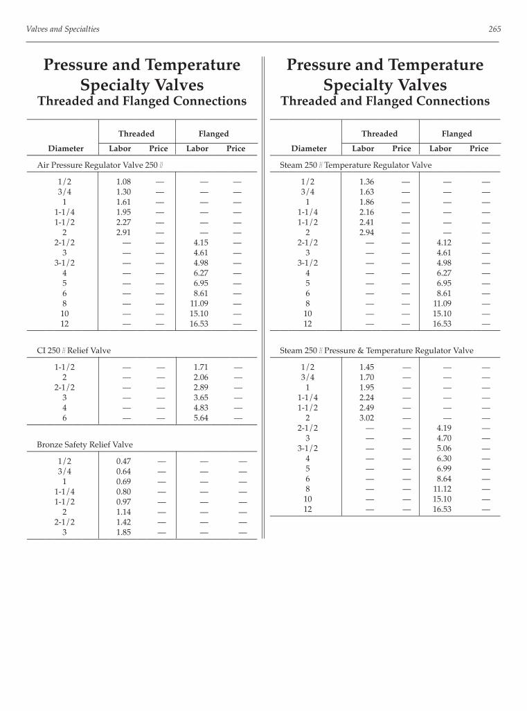
Valves and Specialties 265
Pressure and TemperatureSpecialty Valves
Threaded and Flanged Connections—————————————————————————
Threaded Flanged
Diameter Labor Price Labor Price————————————————————————— Air Pressure Regulator Valve 250#————————————————————————— 1/2 1.08 — — — 3/4 1.30 — — — 1 1.61 — — — 1-1/4 1.95 — — — 1-1/2 2.27 — — — 2 2.91 — — — 2-1/2 — — 4.15 — 3 — — 4.61 — 3-1/2 — — 4.98 — 4 — — 6.27 — 5 — — 6.95 — 6 — — 8.61 — 8 — — 11.09 — 10 — — 15.10 — 12 — — 16.53 ——————————————————————————
CI 250# Relief Valve————————————————————————— 1-1/2 — — 1.71 — 2 — — 2.06 — 2-1/2 — — 2.89 — 3 — — 3.65 — 4 — — 4.83 — 6 — — 5.64 ——————————————————————————
Bronze Safety Relief Valve————————————————————————— 1/2 0.47 — — — 3/4 0.64 — — — 1 0.69 — — — 1-1/4 0.80 — — — 1-1/2 0.97 — — — 2 1.14 — — — 2-1/2 1.42 — — — 3 1.85 — — ——————————————————————————
Pressure and TemperatureSpecialty Valves
Threaded and Flanged Connections—————————————————————————
Threaded Flanged
Diameter Labor Price Labor Price————————————————————————— Steam 250# Temperature Regulator Valve————————————————————————— 1/2 1.36 — — — 3/4 1.63 — — — 1 1.86 — — — 1-1/4 2.16 — — — 1-1/2 2.41 — — — 2 2.94 — — — 2-1/2 — — 4.12 — 3 — — 4.61 — 3-1/2 — — 4.98 — 4 — — 6.27 — 5 — — 6.95 — 6 — — 8.61 — 8 — — 11.09 — 10 — — 15.10 — 12 — — 16.53 ——————————————————————————
Steam 250# Pressure & Temperature Regulator Valve————————————————————————— 1/2 1.45 — — — 3/4 1.70 — — — 1 1.95 — — — 1-1/4 2.24 — — — 1-1/2 2.49 — — — 2 3.02 — — — 2-1/2 — — 4.19 — 3 — — 4.70 — 3-1/2 — — 5.06 — 4 — — 6.30 — 5 — — 6.99 — 6 — — 8.64 — 8 — — 11.12 — 10 — — 15.10 — 12 — — 16.53 ——————————————————————————

266 Mechanical Estimating Manual
Balancing Specialty ValvesThreaded and Flanged Connections
—————————————————————————
Threaded Flanged
Diameter Labor Price Labor Price————————————————————————— Circuit Setter————————————————————————— 1/2 0.37 $55 — — 3/4 0.50 55 — — 1 0.62 85 — — 1-1/4 0.73 120 — — 1-1/2 0.81 140 — — 2 1.01 200 — — 2-1/2 1.61 375 — — 3 1.95 595 — — 4 — — 2.27 $835—————————————————————————
Balancing Cock Valve————————————————————————— 1/2 0.32 — — — — 3/4 0.45 — — — — 1 0.55 — — — — 1-1/4 0.64 — — — 1-1/2 0.73 — — — 2 0.94 — 1.49 — — 2-1/2 1.49 — 1.81 — 3 1.85 — 2.16 — — 4 — — 2.67 — — 5 — — 3.49 — — 6 — — 4.35 — — 8 — — 5.30 — — 10 — — 7.42 — — 12 — — 8.55 — — 14 — — 9.56 — — 16 — — 9.60 — — 18 — — 11.78 — — 20 — — 12.59 — ——————————————————————————
Balancing Specialty ValvesFlanged Connections
—————————————————————————
Flanged
Diameter Labor Price————————————————————————— Pattern————————————————————————— 2 2.64 $400 2-1/2 3.18 465 3 3.81 505 4 4.72 1,070 5 6.17 1,265 6 7.69 1,420 8 9.34 2,255 10 13.09 3,045—————————————————————————
Triple Duty Valve Straight Pattern————————————————————————— 2 2.64 $400 2-1/2 3.18 465 3 3.81 505 4 4.72 1,070 5 6.17 1,265 6 7.69 1,735 8 9.34 2,355 10 13.09 3,885 12 15.09 5,970 14 16.87 7,270—————————————————————————
CI 125 Venturi Valve————————————————————————— 4 2.27 — 6 2.94 — 8 4.07 — 10 5.12 — 12 6.78 — 14 7.37 — 16 9.25 — 18 10.47 — 20 11.67 — 24 12.36 ——————————————————————————

Valves and Specialties 267
Balancing Specialty ValvesGrooved Connections
—————————————————————————
Grooved
Diameter Labor Price————————————————————————— Venturi Valve————————————————————————— 2-1/2 0.59 — 3 0.71. — 4 0.94 — 5 1.38 — 6 1.67 — 8 2.26 — 10 2.88 — 12 3.25 — 14 3.50 — 16 3.90 — 18 5.21 — 20 5.71 — 24 7.36 ——————————————————————————
Hot Water SpecialtiesThreaded and Flanged Connections
—————————————————————————
Threaded Flanged
Diameter Labor Price Labor Price————————————————————————— Air Separator with Strainer————————————————————————— 2 1.60 $735 — — 2-1/2 2.44 830 — — 3 2.83 1,270 — — 4 — — 3.06 $1,830 5 — — 4.36 2,335 6 — — 5.23 2,795 8 — — 5.62 4,170 10 — — 7.57 6,560 12 — — 8.88 9,430 14 — — 9.80 19,020 16 — — 10.72 23,790—————————————————————————
Air Separator without Strainer————————————————————————— 2 1.60 $585 — — — 2-1/2 2.44 680 — — 3 2.83 960 — — — 4 — — 3.06 $1,505 — 5 — — 4.36 2,005 — 6 — — 5.23 2,345 — 8 — — 5.62 3,210 — 10 — — 7.57 4,900 — 12 — — 8.88 7,745 — 14 — — 9.80 14,150 — 16 — — 10.72 16,030 ——————————————————————————
Hot Water Specialties————————————————————————— Diameter Labor Price————————————————————————— Air Purger————————————————————————— 1/2 0.52 — 3/4 0.71 — 1 0.84 — 1-1/4 0.96 — 1-1/2 1.02 — 2 1.15 —
—————————————————————————
Aerator————————————————————————— 3 2.87 — 4 4.70 — 5 6.94 — 6 12.89 ——————————————————————————
Air Vent————————————————————————— 1/2 0.52 $89.00 3/4 0.71 89.00 1 0.84 — 1-1/2 1.02 — 2 1.15 ——————————————————————————
Air Bleeder————————————————————————— 1/2 0.52 — 3/4 0.71 — 1 0.84 — 1-1/4 0.96 — 1-1/2 1.02 — 2 1.15 — 2-1/2 1.26 — 3 1.40 — 4 2.37 — 5 3.04 — 6 3.53 — 8 4.76 — 10 6.52 ——————————————————————————

268 Mechanical Estimating Manual
Hot Water SpecialtiesFlanged and Grooved Connections
—————————————————————————
Flanged Grooved
Diameter Labor Price Labor Price————————————————————————— Suction Diffuser, 200 PSI————————————————————————— 2 1.41 $279 — — 2-1/2 1.88 366- — — 3 1.92 432 — — 4 3.06 612 — — 5 4.36 691 — — 6 5.23 945 — — 8 5.62 1,879 — — 10 7.57 2,639 — — 12 8.88 3,785 — — 14 9.80 — — —
—————————————————————————
Suction Diffuser, 300 PSI————————————————————————— 2 1.41 $453 0.89 $268 2-1/2 1.88 543 0.89 359 3 1.92 727 0.89 416 4 3.06 962 1.37 590 6 5.23 1,130 2.77 962 8 5.62 2,233 3.11 1,455 10 7.57 4,206 4.00 2,759—————————————————————————
Hot Water Specialties————————————————————————— Diameter Labor Price————————————————————————— Cock, Single Threaded ————————————————————————— 1/8 0.35 $4.15 1/4 0.35 4.50 3/8 0.35 4.95 1/2 0.35 5.05—————————————————————————
Cock, Double Threaded————————————————————————— 1/8 0.35 $5.55 1/4 0.35 5.40 3/8 0.35 5.90 1/2 0.35 7.10—————————————————————————
Manual Air Vent————————————————————————— 1/2 0.52 — 3/4 0.71 — 1 0.84 — 1-1/2 1.02 — 2 1.15 ——————————————————————————
Refrigeration Specialties————————————————————————— Diameter Labor Price————————————————————————— Indicator Sight Glass, Soldered————————————————————————— 1/2 0.59 — 3/4 0.69 — 1 0.76 — 1-1/4 0.81 — 1-1/2 0.84 — 2 0.92 ——————————————————————————
Suction Line Filter Drier I Core————————————————————————— 3/4 1.38 — 1 1.53 — 1-1/4 1.67 — 1-1/2 1.74 ——————————————————————————
Suction Line Filter Drier 3 Core————————————————————————— 1-1/4 1.72 — 1-1/2 2.18 — 2-1/2 2.31 ——————————————————————————
Suction Line Filter Drier 4 Core————————————————————————— 1-1/4 1.78 — 1-1/2 1.86 — 2 2.41 — 3 3.54 — 4 4.30 ——————————————————————————
Sealed Filter Drier, Flared————————————————————————— 1/2 0.54 — 3/4 0.54 — 1 0.57 ——————————————————————————
Sealed Filter Drier, Soldered————————————————————————— 1/2 1.04 — 3/4 1.21 — 1 1.36 ——————————————————————————

Valves and Specialties 269
Refrigeration SpecialtiesRefrigeration Valves
—————————————————————————
Soldered Threaded
Diameter Labor Price Labor Price————————————————————————— Expansion Valve————————————————————————— 1/2 1.24 — 1.42 — 3/4 1.47 — 1.71 — 1 1.67 — 1.93 — 1-1/4 1.86 — — — 1-1/2 1.97 — — —
—————————————————————————
Solenoid Valve Pilot Operated————————————————————————— 1/2 1.24 — 1.36 — 3/4 1.47 — 1.66 — 1 1.65 — 1.88 — 1-1/4 1.78 — 2.12 — 1-1/2 2.31 — 2.74 — 2 2.62 — 3.23 — 2-1/2 3.67 — 4.57 —
—————————————————————————
Stop Valve————————————————————————— 1/4 — $12.73 — — 3/8 — 10.97 — — 1/2 — 10.97 — — 3/4 — 13.65 — — 1 — 19.86 — — 1-1/4 — 26.95 — — 1-1/2 — 41.72 — — 2 — 59.21 — —
—————————————————————————
Relief Valve, Soldered————————————————————————— 1/2 0.25 — — — — 3/4 0.32 $36 — — — 1 0.42 60 — — — 1-1/4 0.47 90 — — 1-1/2 — 130 — — 2 — 185 — — ——————————————————————————
Refrigeration SpecialtiesRefrigeration ACR Valves
————————————————————————— Diameter Labor Price————————————————————————— Sight Glass————————————————————————— 5/8 0.59 — 7/8 0.69 — 1-1/8 0.76 — 1-3/8 0.81 — 1-5/8 0.84 — 2-1/8 0.92 —
—————————————————————————
Filter Dryer————————————————————————— 5/8 1.11 — 7/8 1.32 — 1-1/8 1.53 — 1-3/8 1.62 — 1-5/8 1.69 — 2-1/8 — — 2-5/8 — — 3-1/8 — — 4-1/8 — ——————————————————————————
Steam Specialties————————————————————————— Diameter Labor Price————————————————————————— Vacuum Breaker Water-Anti Siphon————————————————————————— 1/2 0.60 $14.85 3/4 0.78 17.55 1 0.85 27.45 1-1/4 0.94 45.50 1-1/2 1.02 53.50 2 1.18 83.20 2-1/2 1.84 240.00 3 2.12 318.00—————————————————————————
Cock————————————————————————— 1/8 — $9.80 1/4 — 9.80 3/8 — 9.70 1/2 — 9.20 3/4 — 10.00 1 — 18.65 1-1/4 — 21.25 1-1/2 — 30.50 2 — 48.00—————————————————————————

270 Mechanical Estimating Manual
Steam Specialties————————————————————————— Diameter Labor Price————————————————————————— Steam Separator————————————————————————— 1/4 — $84.00 1/2 — 90.00 3/4 — 95.00 1 — 142.00 1-1/4 — 163.00 1-1/2 — 184.00 2 — 205.00 2-1/2 — 720.00 3 — 815.00 4 — 920.00 5 — 1130.00 6 — 1370.00 8 — 1680.00 10 — 2360.00 12 — 3960.00 14 — 5280.00—————————————————————————
Chilled Water Specialties————————————————————————— Diameter Labor Price————————————————————————— Sight Glass————————————————————————— 1/2 0.59 — 3/4 0.69 — 1 0.76 — 1-1/4 0.81 — 1-1/2 0.84 — 2 0.92 ——————————————————————————

271
Chapter 19
DWV Pipe and Fittings
This chapter covers labor and price tables for DW (drain, waste and vent) piping and fi ttings as follows:
DWV Pipe and Fittings:• Copper DVVV Pipe and Wrot Copper DWV
Fittings• PVC DWV Schedule 40• ABS DWV Schedule 40• Cast Iron Hub and Spigot• Cast Iron No Hub
Units All diameters are in inches. Refer to chapter 17 for hangers.
Labor The labor productivity rates in the tables are what the average mechanic under average conditions can erect on lower fl oors of construction projects. However, they may require the application of labor correction factors for variable conditions such as upper fl oors, higher piping runs, congested spaces, etc. The labor in the tables are in hours per piece and hours per foot for pipe.
Pricing and Discounts The pricing in the tables are based on the typical manufacturers list prices and the contractor’s supplier discounts must be applied.
Appropriate price discounts can range from roughly 10 percent to 80 percent dependent on the following:• Supplier discount structure• Who manufacturer is• Size of batch involved• Availability• Shipping distance, costs
Not All List Prices Are Publicly Available Where there are no prices listed in tables, they are not usually publicly available from the manufacturer. If there is neither labor nor prices listed for a particular diameter in the tables, the particular item may not be available or it may not be a commonly used item.
Caution With List Prices Pricing can sometimes vary signifi cantly because of changes in commodity material pricing such as copper, etc. Periodic checks of current fi st prices should be made. If in doubt about your discounts from list prices, check with your supplier as to what they are for the various categories of items - or request a quotation.
Automatic Updating Available inWendes Computer System Automatic updating of list pricing is available in the Wendes Computerized Piping Estimating System. Call (847) 808-8371 for more information.

272 Mechanical Estimating Manual
Copper DWV Pipe and FittingsSoldered Connections
——————————————————————————————————————————
Pipe 1/4 Bend 1/8 Bend 1/16 Bend
Dia. Labor Price Labor Price Labor Price Labor Price——————————————————————————————————————————
1-1/4 0.06 $2.34 0.50 $3.53 0.50 $3.23 0.50 $5.80
1-1/2 0.06 2.95 0.52 4.73 0.52 2.69 0.52 7.62
2 0.06 3.90 0.60 6.87 0.60 6.16 0.60 9.87
3 0.08 6.16 1.15 16.98 1.15 13.04 1.15 16.69
4 0.10 11.10 1.53 80.13 1.53 55.12 1.53 68.00
5 0.15 34.38 — — — — — —
6 0.18 47.55 — — — — — —
8 0.22 86.42 — — — — — ———————————————————————————————————————————
——————————————————————————————————————————
Double Sanitary Tee Dbl Sanitary Tee Wye
Dia. Labor Price Labor Price Labor Price Labor Price——————————————————————————————————————————
1-1/4 0.71 $14.45 0.71 $6.94 1.03 $17.73 0.71 $13.24
1-1/2 0.76 21.39 0.76 8.64 1.09 15.42 0.76 14.41
2 0.88 33.97 0.88 10.08 1.29 37.42 0.88 19.79
3 — — 1.70 35.96 2.50 54.50 1.70 45.28
4 — 2.29 91.24 3.39 253.00 2.29 91.24 —
5 — — — — — — — —
6 — — — — — — — ———————————————————————————————————————————

DWV Pipe and Fittings 273
Copper DWV Pipe and FittingsSoldered Connections
——————————————————————————————————————————
Tee-Wye LT Dbl Wye P-Trap Test Cap
Dia. Labor Price Labor Price Labor Price Labor Price——————————————————————————————————————————
1-1/4 0.71 $19.49 — — 0.50 $23.55 0.25 $0.62
1-1/2 0.76 16.08 1.09 $23.03 0.52 23.47 0.29 0.63
2 0.88 35.65 1.29 37.82 0.60 36.27 0.31 1.36
3 1.70 62.99 2.50 667.16 1.15 87.54 0.59 2.77
4 2.29 165.00 — — — 0.77 5.62 —
5 — — — — — — — —
6 — — — — — — — —
8 — — — — — — — ———————————————————————————————————————————
——————————————————————————————————————————
Fitting Plug Ftg Cleanout Coupling Repair Cplg
Dia. Labor Price Labor Price Labor Price Labor Price——————————————————————————————————————————
1-1/4 — — 0.25 $11.23 0.50 $1.64 0.50 $2.38
1-1/2 — — 0.29 15.26 0.52 2.05 0.52 2.43
2 0.03 $4.92 0.31 18.06 0.59 2.83 0.59 3.31
3 — — 0.59 57.43 1.13 5.48 1.13 5.74
4 — — 0.77 72.25 1.51 13.17 1.51 15.24
5 — — — — — — — —
6 — — — — — — — —
8 — — — — — — — ———————————————————————————————————————————

274 Mechanical Estimating Manual
PVC DWV Schedule 40Solvent and Fusion Connections
—————————————————————————————————————————————
Pipe 1/4 Bend 1/4 Double Bend
Labor Price Labor Price Labor Price
Dia. Solvent Fusion Solvent Fusion Solvent Fusion—————————————————————————————————————————————
1-1/4 0.04 0.04 $1.15 0.16 0.48 $1.77 — — —
1-1/2 0.04 0.04 1.26 0.16 0.48 0.89 0.23 0.71 $3.65
2 0.04 0.04 1.64 0.18 0.55 1.38 0.27 0.81 5.11
3 0.05 0.05 3.38 0.24 0.82 3.41 0.34 1.20 15.66
4 0.06 0.06 4.80 0.35 1.07 6.13 — — —
6 0.08 0.08 8.89 0.60 1.59 37.29 — — —
8 0.10 0.10 13.91 0.82 2.16 75.53 — — —
10 — — — 1.11 2.94 118.61 — — —
12 — — — 1.51 3.99 182.45 — — —
14 — — — 2.06 5.43 244.34 — — —
16 — — — 2.80 7.39 362.34 — — ——————————————————————————————————————————————
—————————————————————————————————————————————
Return Bend 1/8 Bend 1/6 Bend
Labor Price Labor Price Labor Price
Dia. Solvent Fusion Solvent Fusion Solvent Fusion—————————————————————————————————————————————
1-1/4 — — — 0.16 0.48 $1.79 — — —
1-1/2 0.16 0.48 $2.95 0.16 0.48 0.99 0.16 0.48 $1.79
2 0.18 0.55 5.67 0.18 0.55 1.44 0.18 0.55 2.68
3 0.24 0.82 15.77 0.23 0.81 2.94 0.23 0.81 9.51
4 0.35 1.07 31.44 0.34 1.07 4.89 0.34 1.07 13.52
6 — — — 0.59 1.59 34.13 0.59 1.59 59.91
8 — — — —0.80 2.16 67.86 0.80 2.16 85.48
10 — — — —1.08 2.93 98.72 1.08 2.93 143.24
12 — — — —1.48 3.99 138.65 1.48 3.99 187.67
14 — — — —2.01 5.42 240.43 2.01 5.42 344.00
16 — — — —2.73 7.37 264.22 2.73 7.37 418.23—————————————————————————————————————————————

DWV Pipe and Fittings 275
PVC DWV Schedule 40Solvent and Fusion Connections
—————————————————————————————————————————————
1/16 Bend 1/12 Bend 1/24 & 1/32 Bend
Labor Price Labor Price Labor Price
Dia. Solvent Fusion Solvent Fusion Solvent Fusion—————————————————————————————————————————————
1-1/4 — — — — — — — — —
1-1/2 0.16 0.48 $1.47 — — — — — —
2 0.18 0.55 1.98 — — — — — —
3 0.23 0.81 5.09 — — — — — —
4 0.34 1.06 7.74 0.34 1.06 $33.92 0.34 1.06 $19.27
6 0.59 1.59 42.83 0.59 1.59 52.96 0.59 1.59 31.01
8 0.80 2.16 52.43 0.80 2.16 76.54 0.80 2.16 52.43
10 1.08 2.93 79.12 1.08 2.93 115.27 1.08 2.93 79.12
12 1.48 3.99 125.16 1.48 3.99 141.27 1.48 3.99 125.16
14 2.01 5.42 187.58 2.01 5.42 238.64 2.01 5.42 196.77
16 2.73 7.37 255.60 2.73 7.37 329.52 2.73 7.37 268.24—————————————————————————————————————————————
—————————————————————————————————————————————
Vent Tee Sanitary Tee Wye
Labor Price Labor Price Labor Price
Dia. Solvent Fusion Solvent Fusion Solvent Fusion—————————————————————————————————————————————
1-1/4 — — — 0.22 0.71 $3.15 0.23 0.71 $3.02
1-1/2 0.22 0.71 $4.98 0.22 0.71 1.32 0.23 0.71 2.62
2 0.26 0.81 3.51 0.26 0.81 1.81 0.27 0.81 2.63
3 0.34 1.20 13.15 0.34 1.20 4.99 0.34 1.20 5.97
4 0.50 1.59 15.79 0.50 1.59 9.51 0.51 1.60 11.12
6 — — — 0.87 2.37 55.31 0.87 2.39 55.66
8 — — — 1.20 3.26 165.55 1.23 3.39 119.16
10 1.81 4.94 173.34 1.81 4.94 416.80 1.81 4.98 164.23
12 2.75 7.50 230.36 2.75 7.50 476.40 2.75 7.57 243.27
14 3.44 9.37 452.82 3.44 9.37 834.82 3.44 9.45 477.25
16 4.29 11.69 640.96 4.29 11.69 1161.66 4.29 11.80 548.13—————————————————————————————————————————————

276 Mechanical Estimating Manual
PVC DWV Schedule 40Solvent and Fusion Connections
—————————————————————————————————————————————
Double Wye Slip Cross P-Trap w/Chrome Nut
Labor Price Labor Price Labor Price
Dia. Solvent Fusion Solvent Fusion Solvent Fusion—————————————————————————————————————————————
1-1/4 — — — — — — — — —
1-1/2 0.29 0.94 $5.58 — — — 0.17 0.48 $2.57
2 0.34 1.06 7.18 — — — 0.19 0.56 3.49
3 0.44 1.59 18.53 — — — 0.19 0.82 17.40
4 0.66 2.11 37.56 — — — 0.19 1.08 42.00
6 1.21 3.15 73.85 1.17 3.15 $70.28 — — —
8 1.65 4.30 112.54 1.58 4.26 123.31 — — —
10 2.50 6.50 206.33 2.39 6.44 231.07 — — —
12 3.79 9.86 336.84 3.63 9.77 304.62 — — —
14 4.75 12.34 496.01 4.54 12.20 506.04 — — —
16 5.92 15.40 627.33 5.66 15.23 739.22 — — ——————————————————————————————————————————————
—————————————————————————————————————————————
Adapter HxF Adapter HxM Expansion Joint
Labor Price Labor Price Labor Price
Dia. Solvent Fusion Solvent Fusion Solvent Fusion—————————————————————————————————————————————
1-1/4 — — — — — — — — —
1-1/2 0.29 0.94 $5.58 — — — 0.17 0.48 $2.57
2 0.34 1.06 7.18 — — — 0.19 0.56 3.49
3 0.44 1.59 18.53 — — — 0.19 0.82 17.40
4 0.66 2.11 37.56 — — — 0.19 1.08 42.00
6 1.21 3.15 73.85 1.17 3.15 $70.28 — — —
8 1.65 4.30 112.54 1.58 4.26 123.31 — — —
10 2.50 6.50 206.33 2.39 6.44 231.07 — — —
12 3.79 9.86 336.84 3.63 9.77 304.62 — — —
14 4.75 12.34 496.01 4.54 12.20 506.04 — — —
16 5.92 15.40 627.33 5.66 15.23 739.22 — — ——————————————————————————————————————————————

DWV Pipe and Fittings 277
PVC DWV Schedule 40Solvent and Fusion Connections
—————————————————————————————————————————————
Slip Cap Spigot Plug Coupling HxH
Labor Price Labor Price Labor Price
Dia. Solvent Fusion Solvent Fusion Solvent Fusion—————————————————————————————————————————————
1-1/4 — — — — — — 0.16 0.48 $1.70
1-1/2 0.10 0.25 $2.26 0.10 0.25. $6.19 0.16 0.48 0.57
2 0.11 0.29 3.75 0.11 0.29 10.17 0.18 0.55 0.59
3 0.13 0.34 6.51 — — — 0.23 0.81 1.70
4 0.17 0.43 9.30 — — 1 0.34 1.06 2.79
6 0.28 0.78 23.48 0.28 0.73 21.23 0.57 1.59 14.94
8 0.42 — — 0.42 1.09 54.22 0.78 1.59 33.64
10 0.70 1.82 54.92 0.70 1.82 61.83 0.99 2.02 38.61
12 1.06 2.76 69.35 1.06 2.76 79.77 1.20 2.45 43.67
14 1.33 3.46 117.92 1.33 3.46 117.92 1.45 2.97 100.61
16 1.66 4.31 150.96 1.66 4.31 183.24 1.76 3.60 112.21—————————————————————————————————————————————

278 Mechanical Estimating Manual
ABS DWV Schedule 40Solvent and Fusion Connections
—————————————————————————————————————————————
Pipe 1/4 Bend 1/4 Double Bend
Labor Price Labor Price Labor Price
Dia. Solvent Fusion Solvent Fusion Solvent Fusion—————————————————————————————————————————————
1-1/4 — — — 0.16 0.48 $2.05 — — —
1-1/2 0.06 — $2.70 0.16 0.48 1.09 0.23 0.71 $4.22
2 0.08 — 3.45 0.18 0.55 1.79 0.27 0.81 5.90
3 0.10 — 6.90 0.24 0.82 4.24 0.34 1.20 18.08
4 0.13 — 9.95 0.35 1.07 7.38 — — —
6 0.17 — 19.25 0.60 1.59 46.57 — — ——————————————————————————————————————————————
—————————————————————————————————————————————
Return Bend 1/8 Bend 1/6 Bend
Labor Price Labor Price Labor Price
Dia. Solvent Fusion Solvent Fusion Solvent Fusion—————————————————————————————————————————————
1-1/4 — — — 0.16 0.48 $2.07 — — —
1-1/2 0.16 0.48 $3.35 0.16 0.48 1.17 0.16 0.48 $1.96
2 0.18 0.55 5.83 0.18 0.55 1.74 0.18 0.55 3.14
3 0.24 0.82 16.70 0.23 0.81 3.88 0.24 0.81 11.00
4 0.35 1.07 35.79 0.34 1.07 6.19 0.35 1.07 16.09
6 — — — 0.59 1.60 37.21 — — ——————————————————————————————————————————————
—————————————————————————————————————————————
1/6 Bend Vent Tee Sanitary Tee
Labor Price Labor Price Labor Price
Dia. Solvent Fusion Solvent Fusion Solvent Fusion—————————————————————————————————————————————
1-1/4 — — — — — — 0.22 0.71 $2.58
1-1/2 0.16 0.48 $1.71 0.22 0.48 $4.47 0.22 0.71 1.60
2 0.18 0.55 2.28 0.26 0.55 4.06 0.26 0.81 2.27
3 0.23 0.81 5.88 0.34 0.82 15.19 0.34 1.20 5.76
4 0.34 1.06 8.96 0.50 1.59 19.96 0.50 1.59 14.29
6 0.59 1.60 72.75 — — — 0.87 2.37 68.94—————————————————————————————————————————————

DWV Pipe and Fittings 279
ABS DWV Schedule 40Solvent and Fusion Connections
—————————————————————————————————————————————
Wye Double Wye Expansion Joint
Labor Price Labor Price Labor Price
Dia. Solvent Fusion Solvent Fusion Solvent Fusion—————————————————————————————————————————————
1-1/4 0.23 0.71 $2.98 — — — — — —
1-1/2 0.23 0.71 3.03 0.29 0.94 $6.44 — — —
2 0.27 0.81 3.11 0.34 1.06 8.29 0.18 0.55 $193.87
3 0.34 1.20 7.16 0.44 1.59 21.43 0.24 0.82 211.61
4 0.51 1.60 16.97 0.66 2.11 43.41 0.35 1.07 349.70
6 0.87 2.39 64.33 — — — — — ——————————————————————————————————————————————
—————————————————————————————————————————————
Adapter HxF Adapter HxM Coupling
Labor Price Labor Price Labor Price
Dia. Solvent Fusion Solvent Fusion Solvent Fusion—————————————————————————————————————————————
1-1/4 — — — 0.33 0.59 $1.44 0.16 0.48 $1.15
1-1/2 0.36 0.64 $1.20 0.36 0.64 1.04 0.16 0.48 0.68
2 0.43 0.76 1.93 0.43 0.76 1.52 0.18 0.55 0.71
3 0.78 1.25 5.25 0.78 1.25 4.43 0.23 0.81 2.38
4 1.03 1.66 6.61 1.03 1.66 9.81 0.34 1.06 3.65
6 1.57 1.66 22.55 — — — 0.57 1.59 19.30—————————————————————————————————————————————
—————————————————————————————————————————————
P-Trap Cap Hub Pipe Test Cap
Labor Price Labor Price Labor Price
Dia. Solvent Fusion Solvent Fusion Solvent Fusion—————————————————————————————————————————————
1-1/4 — — — — — — —
1-1/2 0.17 0.48 $3.31 0.03 0.03 $2.36 0.03 0.03 $0.65
2 0.19 0.56 5.36 0.03 0.03 3.78 0.03 0.03 0.6
3 0.19 0.82 24.51 0.03 0.03 6.70 0.03 0.03 0.86
4 0.19 1.08 50.21 0.03 0.03 8.98 0.03 0.03 1.09
6 — — — — — — — — ——————————————————————————————————————————————

280 Mechanical Estimating Manual
Cast Iron Hub and SpigotO-Ring Joint Compression Connections
————————————————————————————————————————
Pipe 10’ Section Pipe 5’ Section 1/4 Bend 1/8 Bend
Dia. Labor Price Labor Price Labor Price Labor Price————————————————————————————————————————
2 0.98 $52.80 0.59 $44.35 0.29 $9.70 0.29 $7.75
3 1.26 72.80 0.80 49.20 0.43 16.80 0.42 14.10
4 1.61 94.65 1.01 63.95 0.58 26.25 0.56 20.50
5 1.89 133.50 1.22 82.90 0.71 36.65 0.69 28.35
6 2.24 162.65 1.47 120.80 0.79 45.70 0.75 34.80
8 3.08 260.95 1.96 181.55 1.08 137.75 1.02 103.90
10 3.99 434.45 2.59 275.95 1.48 201.40 1.36 149.40
12 4.41 631.05 3.11 364.25 1.78 272.85 1.62 283.20
15 5.04 922.35 3.78 540.80 2.81 874.80 2.37 565.00————————————————————————————————————————
————————————————————————————————————————
1/5 Bend 1/6 Bend 1/16/Bend Pipe Plug
Dia. Labor Price Labor Price Labor Price Labor Price————————————————————————————————————————
2 0.29 $15.95 0.29 $9.70 0.29 $7.75 0.04 $5.15
3 0.42 24.80 0.42 16.70 0.42 12.90 0.06 9.05
4 0.57 36.85 0.57 23.15 0.55 18.00 0.06 10.95
5 0.71 47.90 0.71 38.35 0.66 27.05 0.08 21.20
6 0.78 52.05 0.78 54.10 0.73 30.30 0.10 20.60
8 — — 1.07 124.75 0.99 106.40 0.15 50.50
10 — — 1.29 247.70 1.29 163.55 0.21 71.10
12 — — — — 1.62 384.75 0.31 103.80
15 — — — — 2.37 449.10 0.41 178.20————————————————————————————————————————
Pipe pricing and labor for Cast Iron Hub and Spigot is per section. Divide section length to get
per foot price and labor values.

DWV Pipe and Fittings 281
Cast Iron Hub and SpigotO-Ring Joint Compression Connections
————————————————————————————————————————
Wye Dbl Wye Sanitary Tee Sanitary Cross
Dia. Labor Price Labor Price Labor Price Labor Price————————————————————————————————————————
2 0.54 $16.05 0.77 $26.55 0.54 $15.45 0.77 $24.45
3 0.82 29.55 1.17 45.95 0.81 28.35 1.15 42.45
4 1.07 39.70 1.57 63.70 1.06 334.80 1.53 58.00
5 1.34 66.90 1.95 102.80 1.30 69.15 1.80 83.60
6 1.49 91.40 2.16 163.80 1.46 78.50 2.02 136.10
8 1.99 223.50 2.87 401.05 1.93 228.10 2.67 261.10
10 2.75 361.25 3.88 563.40 2.58 381.50 — —
12 3.28 621.05 4.59 812.70 3.04 635.35 — —
15 4.15 1316.10 5.10 2449.50 4.15 1429.95 — —————————————————————————————————————————
————————————————————————————————————————
Spigot Vent Cap Hub End Vnt Cp Vent Cap w/Screw Dbl Hub Ftg
Dia. Labor Price Labor Price Labor Price Labor Price————————————————————————————————————————
2 — — — — 0.04 $7.70 0.50 $11.65
3 — — — — 0.06 10.90 0.73 19.30
4 0.06 $28.60 0.06 $29.70 .0.06 19.50 0.98 21.95
5 — — — — 0.08 25.30 1.20 42.15
6 0.10 47.85 — — — — 1.30 43.20
8 — — — — — — 1.66 107.15
10 — — — — — — 2.25 238.80
12 — — — — — — 2.56 340.55
15 — — — — — — 3.16 475.95————————————————————————————————————————
Cast Iron Hub and SpigotO-Ring Joint Compression Connections
————————————————————————————————
Clean Out P-Trap Running Trap
Dia. Labor Price Labor Price Labor Price————————————————————————————————
2 0.04 $5.15 0.33 $20.00 0.33 $25.35
3 0.06 8.10 0.48 29.55 0.50 42.95
4 0.06 15.55 0.64 43.15 0.66 79.75
5 0.08 22.10 0.94 91.05 0.85 250.10
6 0.10 28.15 1.42 132.95 0.97 368.75
8 0.15 38.95 2.10 378.90 — —
10 0.21 66.95 — — — —
12 — — — — — —
15 — — — — — —————————————————————————————————

282 Mechanical Estimating Manual
Cast Iron No HubNo Hub Connections
————————————————————————————————————————
Pipe 1/4 Bend Dbl 1/4 Bend 1/8 Bend
Dia. Labor Price Labor Price Labor Price Labor Price————————————————————————————————————————
1-1/2 0.08 $5.16 0.21 $7.10 — — 0.21 $5.90
2 0.08 5.28 0.27 7.70 0.39 $17.25 0.27 6.55
3 0.10 7.28 0.40 10.70 0.58 26.40 0.38 8.85
4 0.14 9.47 0.52 15.40 0.78 34.70 0.50 11.25
5 0.16 13.35 0.67 34.45 — — 0.63 24.05
6 0.19 16.27 0.81 38.80 — — 0.76 26.10
8 0.27 26.10 0.99 106.95 — — 0.88 75.20
10 .36 43.45 — — — — 1.23 140.05————————————————————————————————————————
————————————————————————————————————————
1/5 Bend 1/6 Bend 1/16 Bend Blind Plug
Dia. Labor Price Labor Price Labor Price Labor Price————————————————————————————————————————
1-1/2 — — — — 0.20 $6.15 0.12 $3.70
2 0.27 $9.75 0.27 $8.00 0.27 6.75 0.15 3.70
3 0.39 16.95 0.39 9.80 0.38 8.00 0.20 5.55
4 0.52 26.10 0.52 13.55 0.50 9.25 0.27 8.55
5 — — — — 0.62 22.85 0.34 16.00
6 — — — — 0.75 27.70 0.40 16.65
8 — — — — 0.85 43.95 0.44 44.50
10 — — — — — — 0.49 65.50————————————————————————————————————————

DWV Pipe and Fittings 283
Cast Iron No HubNo Hub Connections
————————————————————————————————————————
Sanitary Tee Sanitary Cross Wye Double Wye
Dia. Labor Price Labor Price Labor Price Labor Price————————————————————————————————————————
1-1/2 0.29 $9.80 0.39 $14.10 0.29 $10.00 — —
2 0.39 10.70 0.50 17.85 0.38 10.00 0.50 $15.40
3 0.57 13.00 0.75 27.65 0.57 14.20 0.75 28.35
4 0.76 20.15 1.03 52.30 0.77 23.10 1.03 57.90
5 1.00 57.35 — — 0.99 53.60 — —
6 1.15 58.50 1.27 110.55 1.19 61.60 1.57 102.10
8 1.58 237.05 1.94 241.10 1.47 145.00 1.94 291.50
10 — — — — 2.10 315.35 — —————————————————————————————————————————
————————————————————————
P-Trap Coupling w/Band
Dia Labor Price Labor Price————————————————————————
1-1/2 0.22 $11.75 0.20 $6.95
2 0.29 11.25 0.27 6.95
3 0.42 24.90 0.38 8.25
4 0.60 43.15 0.50 9.85
5 — — 0.62 24.05
6 1.03 104.60 0.75 25.05
8 — — 0.85 47.25
10 — — 1.23 65.05————————————————————————

This page intentionally left blank

Section VI
Contracting for Profi t

This page intentionally left blank

UNDERSTANDING AND APPLYING CORRECTOVERHEAD AND PROFIT FACTORS
Most of the manual to this point has been spent on emphasizing the necessity for making sure direct material and labor costs are covered fully and accurately.However, you may cover direct costs correctly, and still may be short many thousands of dollars on your bid by putting an inadequate markup on the job for overhead and profi t thus despite your success in the fi rst part, you are really no where in the end. Hence, not only must you make sure that the esti-mate of labor and materials is complete and accurate-but also that the profi t and overhead markups on each job bid correspond accurately to the actual fi nances of the com-pany. Hence, the following concepts and defi nitions must be thoroughly understood in the preparation of bids:
DIRECT COSTS
Direct costs are the costs for material, labor, and sub-contractors needed for a job. They are charged directly to the particular project. Labor covers fabrication, installation, drafting, bal-ancing, etc.; materials include raw material and equip-ment; sub-contractors include rentals and these are all normally direct costs. Also, sales tax, permits, bonds, travel costs, room and board are direct type costs which can be attributed directly to a project.
Total direct costs for the year for the $2 million dollar sales con-tractor in the sample illustration are $1,500,000, which is 75 percent of sales.
OVERHEAD COSTS
Overhead costs however, are those costs you cannot charge directly to each specifi c project. They are fi xed and
semi-variable costs that continue on, either 100 percent of the time or to some degree, whether you have work or not. Overhead costs are prorated in varying degrees to all projects. Some of the main ones are:
Offi ce Salaries InterestRent or Owning Costs DepreciationUtilities InsuranceReal Estate Taxes Boats, Lear JetsAuto and Truck Costs Trips to Disney World
Labor draws about two to three times as much indi-rect cost as equipment, materials and sub-contractors do.
Total overhead costs for the year in the sample illustration are $400,000, which is 20 percent of sales.
PROFIT
Profi t is the amount of money you have left over at the end of the year and at the completion of the proj-ects after you have paid out all your direct and overhead costs. Net profi ts are after corporate income taxes are tak-en out. Honest profi t is not a dirty word, but rather a neces-sity for successful business operation in a free functioning economy:
• Profi t pays a return on investment for stockholders• It provides money for capital investments, machin-
ery, buildings, etc.• It provides for replacement, improvements and
growth.• It provides for increases in wages and more fringe
benefi ts for employees• Profi t provides more jobs through expansion• Profi t is the incentive needed to take the risks of a
business, and is the reward for the hard work and risk.
• Profi ts are necessary for a healthy economy.
Chapter 20
Markups for Overhead and Profi t
287

288 Mechanical Estimating Manual
• Profi ts pay taxes to the government
A business cannot survive long without profi ts, and the if the business fails, many parties are hurt, not only the owners, but also employees, creditors, customers, etc.
A company is in business to make money not lose it. Its primary goal is to earn a suffi cient amount of profi t to cover the items listed above.
However, just because someone is in business and must make money to survive, it also doesn’t justify, on the other hand, a carte blanche approach. A business must run responsibly in the context of the overall good of the community, etc. and must meet the following cri-teria:
• The products and services of a company must meet acceptable standards and satisfy needs.
• The business cannot break the law.• It must meet common morality standards• It must provide healthy and safe working condi-
tions for its employees.• It should not adversely effect the environment• It cannot adversely effect other peoples property• It cannot adversely effect the health or safety of the
public in general.
Profi t for the year in the sample illustration is $100,000, which is 5 percent of sales.
RETURN ON INVESTMENT
Given a $2 million sales and a $500,000 capital in-vestment in a company:• If a 20% return on investment is required, (which is
$100,000 based on the $500,000 capital investment), there must be a 5% profi t of $ 100,000 on the sales of $2 million.
• A corporate tax of 25% reduces the profi t to $75,000.
• If $50,000 is spent on new machinery etc. it reduces the net profi t to $25,000 or earnings of 2-1/2% for stockholders.
MARKUP FOR OVERHEAD
Markup for overhead is the amount of money add-ed to direct costs on an estimate to cover overhead costs.
The markup percentage is the ratio to direct costs. Average percentage markup required on jobs dur-ing the year:
$400,000 (yearly overhead costs)/$S1,500,000 (yearly di-rect costs) 27% average (rounded out).
The goal of an overhead markup on the various projects is to recuperate all the actual overhead costs in-curred for the year. Each job must make its proportionate contribution to overhead and plus contribute proportion-ately to the profi t.
MARGIN, GROSS PROFITS
Margin, which is also called gross profi t, is the dif-ference between sales and direct costs,and is equal to the overhead and profi t together.
The margin percentage is the ratio to total sales, as dif-ferentiated from markup, which is the ratio to total direct costs. However, they are both the same thing money wise, but just have different names and different ratio refer-ences.
Margin works from the top down from total sales, as an accountant does, rather than from direct costs up as the estimator does. Margin, obviously then, is always a lower percentage than markup since it is a ratio to a higher base. Hence:
The margin in the illustration is $500,000 and includes the overhead and profi t for the year.
The $500,000, as a ratio to $2 million sales, is 25%.
The $500,000, as a ratio to direct costs to $1,500,000, is 33 %.
METHODS OF DETERMININGPERCENTAGE MARKUPS ON COSTS
Single Markup On Labor and Materials for Overhead A single markup for overhead, which is a percent-age of the combined total of direct labor and material costs, is the basic and clearest approach in marking up jobs. Whether estimating or monitoring jobs, when you have them, you should always know what the average percentage should be. It is a starting and reference point and gives you a vital overall view.

Markups for Overhead and Profi t 289
$400,000 overhead 27% average markup——————————— = required on $1,500,000 direct costs direct costs
$500,000 overhead and profi t 33% average markup ————————— = required on $1,5000,000 direct costs
PROFIT MARKUPS
The markup for profi t should generally be kept sep-arate from the overhead markup so that overhead can be covered more accurately and distinctly in the bid. Then, when it is necessary to trim the price on a bid to be more competitive, it is easier to only focus on reducing the prof-it, rather than the overhead.
An estimator, when preparing a bid, works up the direct costs on the project fi rst and then “markups”
to cover overhead and profi t as a ratio to direct costs. The accountant, in his fi nancial statements, deals
with the percentage overhead and profi t as a ratio to the total sales fi gure.

290 Mechanical Estimating Manual
MULTIPLE MARKUPS
The multiple markup method puts a different per-centage markups on labor and material. Even though a single markup on material and labor is easy to apply and correlates well to fi nancial statements, it frequently is not a competitive approach to bidding because it may not place the bulk of the overhead on where it properly belongs, which is on labor. As stated previously, since la-bor generally draws more overhead than equipment and materials, it must contribute a larger portion to it. Consequently when applying a multiple markup, a lower percentage is applied on equipment, and a higher one on labor. This more properly and competitively cov-ers the variations in material/labor ratios and is more realistic. The approach here is to select an appropriately lower percentage markup on equipment and subs fi rst, according to your market conditions and material/labor ratios of the project being bid. Then put the balance of the overhead burden on labor.
For example:
Given: Labor Costs ...................................$750,000 Equipment and Subs ...................$750,000
A 10% markup on equipment and subsfor overhead is $75,000,
$400,000 Total overhead – 75,000 Less equipment/subs overhead markup $325,000 Overhead left for labor to cover
Markup percentage needed on labor
$325,000 (Labor Overhead Burden)$750,000 (Labor Costs) Equals a 50% markup needed on labor for overhead
MARKUPS ON LABOR HOURS ONLY
Just adding a markup to direct labor costs, to cover overhead and profi t, can be a simpler, more convenient approach for change orders, time and material orders and possibly for certain type operations according to the pref-erence of the contractor or customer.
For example:
Given: 9 mechanics employed in company = 17,857 man hours/year
If all overhead is covered by labor:
$400,000 Total Overhead = $22.40 which must be added
17,857 Hours onto direct labor costs
$100,000 Total Profi t = $5.60 which must be
17,857 Hours added on also
Direct labor costs with fringes, pay
roll taxes, etc. ................................................. $42.00 per hr
Overhead costs ........................................................ $22.40
Plus 5% Profi t ............................................................ $ 5.60
Total required selling price per hr for labor ........ $70.00
BIDDING STRATEGY REGARDING MARKUPS
You must know what average percentage markup is needed on direct costs during the course of the year to properly cover the actual overhead and profi t fi nal amount at year end. It must be based on anticipated sales, overhead costs and desired profi t and be monitored monthly and adjusted if need be.
Even though you may have to vary your percent-ages at times for various type projects, bidding situ-ations and material labor ratios, the overall average must come out to the percentage determined by yearly sales and overhead.
Overhead must be totally covered for the year no matter what variation in percentages are applied on the estimates.
Each job must make its proper proportionate con-tribution to both overhead and profi t and the total must equal the years total overhead costs and meet the antici-pated profi t.
Situations where You May Vary Your Standard Markup• The markup for overhead might be varied where
the number of bidders is considerably more or less than usual, or where the competitors may change the bidding strategy.
• Jobs which are considerably larger or smaller than your average.
• Where the ratio of materials and subcontractors to labor is greater or less than normal.
• For low risk or higher risk projects than the normal, or those with considerable capital involved.

Markups for Overhead and Profi t 291
Markup Calculation Sheet
The above markup calculation sheet can be used for determining the required level of markups needed for
overhead and profi t for a company using the three methods described in this chapter: 1) a single markup ap-
plied to total direct costs either for overhead alone or for the combination of overhead and profi t as one mark-
up factor. 2) individual, multiple markups for labor, materials and subcontractors. 3) selling cost of labor.

292 Mechanical Estimating Manual
• Where you fi nd you will be closing more work dur-ing the year than you had anticipated; and where overhead will be greater than anticipated; where gross margins on projects are greater than calcu-lated for the year, and you fi nd you have overhead covered ahead of time.
• Potential extras, tenant areas, additions, which produce higher gross margins may infl uence your markup.
• Fast moving, quick completion projects may re-duce overhead costs somewhat.
• Quick paying jobs.
• Anticipated buyouts on equipment and sub-con-tractors may reduce the percentage markup re-quired.
• Large contracts where the cost of money may in-crease the markup percentage needed.
• The markup may be adjusted according to the esti-mators general accuracy. His estimates may be gen-erally higher or lower than actual direct costs.
ODDS OF GETTING JOB
The odds of being low on a bid and getting the con-tract are contingent on the following factors:
• Number of bidders.• Whether being bid as a prime contractor or sub-con-
tractor.• Bidding to owner, architect/engineer or general
contractor.• The effi ciency and productivity of your company
compared to competitors.
Example: If overhead is 20% of sales and you are shooting for a net profi t of 5% before taxes, use 1.33 as a single markup on direct costs.
Single Markup Factors On Direct CostsTo Cover Both Overhead and Desired Profi t
As Percent of Sales

Markups for Overhead and Profi t 293
• Percentage markup you require for overhead and profi t compared to competitors.
• How badly you are in need of work compared to competitors.
• The general accuracy of estimating of the other con-tractors
• How rationally the competitors normally bid.
Income Statement12 Months Ending December 31, 1997(Typical $2 Million Mechanical Contractor)
———————————————————————————————————————— Percent of Amount Sales
Sales $2,000,000 100.00
Direct Costs (variable with volume of work) Material 700,000, 35.00 Sub Contracts 100,000 5.00 Labor 500,000 25.00 Fringes, Insurance, Taxes 200,000
Total Direct Costs 1,500,000 75.00
Gross Margin 500,000 25.00
Overhead Expenses (fi xed and semi fi xed costs) Salaries Offi cers 120,000 6.00 Offi ce 60,000 3.00 Fringe, Insurance, Taxes 40,000 2.00 Rent, 6000 square feet 30,000 1.50 Utilities 10,000 0.50 Insurance - Fire and Theft 20,000 1.00 Taxes - Real Estate 8,000 0.40 Interest 16,000 0.80 Bad Debts 4,000 0.20 Maintenance 8,000 0.40 Expendable Tools 6,000 0.30 Offi ce Supplies 8,000 0.40 Dues 1,000 0.05 Donations 1,000 0.05 Advertising 2,000 0.10 Professional Expenses 4,000 0.20 Auto and Truck, Owning & Operating 20,000 1.00 Sales Expenses 4,000 0.20 Travel and Entertainment 2,000 0.10 Depreciation - Auto and Trucks 20,000 1.00 Depreciation - Machinery and Equipment 10,000 0.50 Depreciation - Building 6,000 0.30 Total Overhead $400,000 20.00 Net Income Before Income Taxes $100,000 5.00
————————————————————————————————————————Typical Income Statement

294 Mechanical Estimating Manual
Balance SheetDecember 31,1997
———————————————————————————————————Assets
Current Assets Cash $100,000 Accounts Receivables 200,000 Inventory 120,000 Work in progress 60,000 Prepaid expenses 10,000 Total current assets $580,000
Fixed Assets Buildings $300,000 Machinery & Equipment 200,000 Autos and Trucks 60,000 Offi ce Equipment 10,000 Total $570,000 Less Depreciation –100,000 $470,000 Plus Land 30,000 Total Fixed Assets $500,000
Other Assets Deposits, Securities 20,000 Total Assets $1,100,000
Liabilities Current Liabilities Accounts Payable $200,000 Taxes Payable 44,000 Debts Payable 6,000 Expenses Payable 40,000 Total Current Liabilities $290,000
Long Term Liabilities Mortgages $ 90,000 Notes 40,000 Total Long Term Liabilities $130,000 Total Liabilities $420,000
Net Worth Capital Stock $200,000 Retained Earnings 280,000 Current Earnings 200,000 Total Net Worth $680,000 Total Liability and Net worth $1,100,000
———————————————————————————————————Typical Balance Sheet

295
WHAT DETERMINES YOUR PROFITABILITYAN OVERALL VIEW
Productivity The number one major factor that determines your profi tability is your productivity rate. For sheet metal contractors the rate of fabrication and installation, what machinery, tools and equipment are owned, the methods used to operate and your quality of manpower are pri-mary factors. Do you fabricate at 22 pounds per hour or 28, or at the average 25? Do you have a duct coil line or a hand break? Productivity between companies can vary 30 or 40 percent. For piping contractors, the rate of erection, fi eld effi ciency and quality of the manpower are primary productivity factors.
Being On Top of the JobAvoiding costly delays, goof-ups, miscoordination, out of sequence work, over manning, waste; the control of all the operations, of timing, being on top of costs, confront-ing problems as they come up, is the 2nd major factor that controls your profi tability. The ductwork or piping for the 2nd fl oor is two weeks late and it costs an extra $1,000 to install because the other trades got in fi rst. Or some equipment doesn’t fi t and it costs you $2,000 to rectify the problem.
Complete and Accurate Estimating You can be off 10 to 20 percent without batting an eye lid. The accuracy of your estimate is a major, constant factor in determining the profi tability of your company. Treat each bid like a new born baby, give it the time and attention it must have to survive.
Correct Markups Hand in hand with estimating direct costs is the proper evaluation of overhead costs, setting of profi t goals, and the adequate application to each bid. The markup money which isn’t covered for overhead comes off the top, which is the profi t layer.
Buyout and Good Purchasing The fi fth most important factor which determines your profi tability is buyout and frugal purchasing. If you bid a job with no commitments to equipment suppliers or to subcontractors, you just accept their bids as received, make no deals, you can well buyout with a 3, 5 or even 10 percent pickup, with a more thorough evaluation after you receive the contract, than is possible at bid time. Many equipment and sub quotes are too high going in, not really competitive and some have contingencies. If you allow your suppliers and subs to reevaluate their pricing, recheck their take-offs and extensions before pur-chasing from them, you frequently uncover errors and infl ated pricing. You may develop cost saving ideas with the additional time and the second look, which can reduce costs. Two suppliers may have bid $22,000 and $24,000 and later found they could trim and polish their bids for something under $20,000. You get several prices on 50,000 pounds of galvanized ductwork and you fi nd some one who can sell it for less per pound.
Selective Bidding Another factor that has a major infl uence on how well you operate, and consequently how you fare eco-nomically, is selective bidding: choosing those jobs you can do well; volume you can handle; projects where you have a history of experience and pricing on; jobs that suit your operations in terms of facilities, machinery, man-power, and management. Do you do well with smaller, shorter simpler proj-ects with multi-skilled tradesmen, and with service op-erations, or is your expertise with large and medium size projects that span 1, 2 or 3 years and which involve highly sophisticated production equipment in your shop, aggressive foremen on the job site, and a wide range of special skills. Selective bidding involves being correctly capital-ized for a project and not having to go out and borrow $100,000 or $200,000 at 12% to run a job. The amount of money you must or must not borrow effects your profi t-ability potential.
Chapter 21
Contracting for Profi t
296 Mechanical Estimating Manual
Timely Payments Timely payments for work you have completed on projects is another factor in your profi t making picture. If you have to wait 6 months, or a year for $20,000 or $50,000 and it’s worth 8 or 10 percent per year, you are hurting money wise and cash fl ow wise. Waiting 60 or 90 days or more for monthly progress payments are damaging to your fi nancial situation. Cash fl ow control is an absolute determinant on your profi tability, and prompt invoicing, follow up and demand of payment within a reasonable time span is a necessity.
Controlling Overhead Overhead can effect you astronomically if left to its own meandering. A $500,000 overhead can jump to $600,000 or $700,000 in a year or two without any increase in business or work load.
Job Costing Job costing and time studies provide the factual fi g-ures for estimates, for production scheduling, progress billing and valid fi nancial reports and can indirectly effect effi ciency and accuracy.
Inventory Control Not having $40,000 worth of uninstalled fans on the job site 6 months, where you have to pay the manu-facturer, but you can’t collect from the owner; or an over abundant supply of galvanized material in the shop, can chew away the dollars that should be profi t in the end.
Bidding and Pricing Strategically Bidding strategy can often provide many extra thou-sands of dollars by not leaving too much on the table, by properly sensing the market and the competition.
Being On Top of Finances Job costing reports and control, regular fi nancial statements and managing cash fl ow effectively are all es-sential for bottom line profi ts.
HOW TO LEGITIMATELYREDUCE COSTS ON A BID
To Be More Competitive
System and Design
1. Redesign An intelligent redesign or change in specifi cations
while still giving the customer the same perfor-mance at a substantially lower price can open many
doors for you. Redesign should always be a consid-eration when looking for ways to reduce costs.
2. Lower Priced Systems• A roof top or split DX system might handle the
customers needs just as well as a chilled water system and costs considerably less.
• Combining a number of small systems together into a larger one can often reduce costs.
• Using a 2 pipe system versus a 3 or 4 pipe can save if feasible.
• Eliminate or minimize return air ductwork if possible.
3. Check for Over-Design A system may be over designed, too full of design
safety fudge factors, excessive capacity, larger sizes than need be, and can be reduced to just what is re-ally needed providing substantial cost reductions.• Where 40 tons of cooling will do the job on a
project instead of an excessive 50 tons, costs can possibly be reduced 10 or 20 thousand dollars.
Ductwork and Piping
4. Reduce Ductwork and Piping Costs Through “STAR” Method of Streamlining• Straighten out ductwork and piping routings.• Maximize duplications of runs and fi ttings.• Optimize arrangement of straight and fi ttings in
runs.• Simplify and standardize fi ttings.
Five hundred feet of ductwork might be cut down to four hundred with more direct and ef-fi cient routing, outlet placement and so on. This can well reduce costs on a $100,000 project to $86,000, a sure winner to get you a job once sub-stantiated.
5. Lower Priced Ductwork or Piping Materials Different materials which work equally as well as
those specifi ed, but cost less, might be offered as a substitution on a bid.• 24 gauge cleated stainless steel ductwork may
be equally resistant to the fumes in a system as PVC ductwork, and costs 20% less.
• Threaded black steel pipe and fi ttings may be 25 to 30 percent less than copper to purchase, and still work equally well in certain applications.
Equipment
6. Lower End Standard Equipment and Systems Ver-sus Deluxe

Contracting for Profi t 297
Deluxe equipment, materials, control systems, construction, accessories, options, etc. may be as extravagant as a Mercedes, whereas standard features and design may be more than satisfactory at a much lower cost.• Use XYZ equipment at $9,000 instead of ABC
equipment at $12,000.• Use an electric control system versus a deluxe
pneumatic.
7. Substitute Lower Price Non-Specifi ed Equipment Substitute non-specifi ed equipment manufacturers
with a lower priced manufacturer who can meet the performance and construction of the specifi ed equipment. This can make the difference in the fi nal low bid price.
8. Pre-Negotiated Equipment and Sub-Contractor Prices
Equipment and sub contractor prices can be negoti-ated at the time of bidding. Agreements can be made and prices might be considerably lower than street prices. This frequently provides a competitive edge.
9. Package Buy at a Discount You may have several projects that will be going at
the same time and can package buy equipment and materials at a volume discount, thereby edging un-der competitors who are pricing the same items in the bid at the street quotations.
Grilles and diffusers for three projects all bought si-multaneously from the same supplier might be fi ve or ten percent cheaper.
Labor
10. Use Lower Priced Labor Where conditions permit you might use helpers,
stockmen, truck drivers, draftsmen, etc. at lower wage rates which may tilt the scales in your favor when bidding.
Machinery and Methods of Operation
11. More Effi cient Productive Machinery or Methods You may plan to buy a high speed forming machine,
coil line, plasma cutter, heavy duty power shear or press break or some other equipment which will in-crease effi ciency. This can be factored into your bid to lower the price and help you be more competitive.
Estimates
12. Recheck Estimate for Overage Errors Errors in estimates are made in both directions. You
may have $5,000 too much in your bid as well as too
little due to math or takeoff errors or poor pricing. This throws you out of the running and you don’t get the job. Recheck estimates thoroughly, not only for loss errors but for overage also.
STAR METHOD OF REDUCINGDUCTWORK AND PIPING COSTS
Standardize and Simplify Ductwork and Piping DesignsCreate DuplicationsArrange Pieces More EconomicallyRoute Runs More Effi cientlyOptimize Ductwork and Pipe Sizing You design and lay out an air distribution system and fi nd that there are 300 pieces of ductwork in it. The current market price for the average size duct section in this design, let’s say, is approximately $150 each. This brings the total price for 300 pieces to $45,000.
Now you take the initial layout and apply the prin-ciple rules of STAR to it for reducing costs. You then recount the pieces and discover that you’ve reduced the number from 300 to 250. You also re-evaluated the cost of each piece and determined that the aver-age price is reduced 10 percent also, from $150 to $135. Consequently, you have slashed the total in-stalled cost of the ductwork 25 percent, a $15,000 saving, from $45,000 to $30,000.
Can this be true, you wonder? So you check wheth-er the calculated performance has been affected and fi nd it unchanged. If anything, the total static pressure drop is lower, the noise level unaltered, air distribution in the spaces still as intended, and anticipated air volume deliv-ery still on target. How can you do this with the same ductwork ma-terials, the same designer, the same contractors and sheet metal men, and the same architectural design?
STAR is the answer, a value analysis approach for reducing total costs while still maintaining function and performance in building piping and ductwork systems. The mnemonic acronym is derived from the four basic elements of the method: S for stan-dardization, simplifi cation and sizing, T for typicals, A for arrangement, and R for routing. But more on these later.
STAR is a method of vigilant search for, and exter-mination of, costs that do not contribute to a system’s ob-jectives and to the user’s needs. Its principles are aimed at

298 Mechanical Estimating Manual
maximum compatibility between performance and cost effi ciency in any pipe or duct conveying system, whether air, liquid, steam, electricity, or otherwise. Its specifi c goals are fewer joints of pipe and fi ttings, more standardized economical ones, more direct routing, and fewer connec-tions, so that labor time is reduced. Material is generally considered secondary in this approach.STAR is a process of revising and polishing, of editing, of whittling away at what is unnecessary and creating more economical alternatives. STAR helps contractors to meet their estimates and to avoid losing money in a hotly competitive market with pricing so low that fi rms cannot afford to manage as they should. The design engineer benefi ts from STAR in that he can get more work through lower cost systems, and he derives the professional satisfaction of designing more effi cient systems. The owner has the most to gain from STAR, how-ever, he gets more for his construction dollar; it’s easier for him to meet budget allocations; there is generally a re-duction in operating costs; his building gets constructed quicker because of the reduced labor hours; and his initial outlay is less. And if he chooses, he can get additional fea-tures in his systems with the money saved through STAR. In some cases, it might enable those who could not other-wise afford to build a chance to do so.
Why Extra Costs Are Built InWhy aren’t all duct and pipe systems designed, fabri-cated, and installed in the most economical and effi cient way? There are at least three basic reasons:
1. The fi rst is a lack of detailed cost knowledge by the designers and even by contractors themselves.
2. The second is that designs are assumed to be the most economical when they’re taken off the boards and sent out for bidding.
3. And third, repeated and objective checking of com-pleted designs to ferret out and eliminate unneces-sary costs that have been built in isn’t done often enough if at all.
Design is a complicated, creative process, involving many engineering considerations and calculations. De-tailed cost reduction can be done more effectively after the design is completed by looking at the entire layout. The consideration and creation of alternate options become more concrete when you have a layout in front of you. There are additional reasons why duct and pipe sys-tems aren’t put in at optimum cost: projects are rushed; experienced and qualifi ed personnel aren’t available; and the additional man-hours of engineering required to trim
costs are not always in the interest of those working on a percent of construction fee basis. Another major reason is that designers do not work closely enough with contractors in the design stage. Con-tractors can provide needed information on detailed costs, results of installation, performance of systems, and problems encountered and solved along the way. The last category of causes for excessive costs in-cludes “shooting from the hip,” “budget load calcula-tion” designs, fudge factors, and contingencies in lieu of precise, thorough, and complete design calculations.
What is Value Analysis? What is value analysis really all about? Here’s an example of one aspect of it. Max Smart, an accountant, wants to buy a car. He’s married, has one child, and doesn’t plan to have any more. His objective is to get rea-sonably comfortable, dependable, quality transportation for three persons for short distance driving.
Max looks at a $40,000 Cadillac fi rst, and this is what he’d love to have most. But he sees there are many unnecessary costs built into this luxurious, power-ful, and spacious automobile that he just doesn’t need. So next he looks at an Oldsmobile. It’s sure nice, too, Max thinks, but it’s the same situation: he just doesn’t need high horsepower, power win-dows, etc. How about a full size Ford or Chevrolet? Naw, he’d still be paying for more pounds of steel and more cubic feet of space than he needs.
Compacts—they’re better, and why not go all the way and get a car that effi ciently uses the energy put into it, has no wasted internal space, is highly reli-able, and will have no unused horsepower. A Toyota sub-compact fi ts the criteria, he decides, and that’s what this objective, analytical gentleman buys, for $12,000. This is $28,000 less than the Cadillac, and Max gets all the satisfactory performance he needs without spending money unnecessarily.
The point here is not to recommend the purchase of an economical foreign car. Rather, it’s that unneces-sary luxuries, over seeing, ineffi cient usage, conspicuous waste, and complexity of products that frequently con-front us in our lives can double, triple, and quadruple the costs of things without giving us the returns we need or want for the extra costs.
Extra Costs: Where to Look There are many categories of unnecessary costs, in addition to those just mentioned, that STAR methodically

Contracting for Profi t 299
attacks. A few of the most important ones are: Using many parts where a few or only one will do
the job. Using many operations, activities, or steps; often an
extensive series can be drastically reduced. Choosing the fi rst solution or design without creat-
ing or considering alternatives. Not having all the pertinent information or neces-
sary facts.False cost savings, where shaving something in one area
causes total costs to increase, such as attaining low-er initial cost through a measure that will increase operating cost inordinately, or vice versa.
Attitudes Don’t Help We also have attitudes that often hinder our applica-tion of value analysis and consequently prevent us from reaching an ultimate cost reduction. Have you ever heard any of these remarks?
“If it doesn’t work, what will happen to me?” “This isn’t the way we do it.” “I know I’m right.” “It won’t work!” “I’m the boss-we do it my way.” “This is what the plans and specs call for, and that’s
the way you’re going to do it.” “What will people think about this?” “This is the way I was told to do it.” “You can’t do it that way. All you want to do is save
yourself money; you don’t care what the customer ends up with.”
“I don’t feel like changing.” “There’s no benefi t in it for me.” “It’s to my disadvantage.”
Beware of these attitudes in yourself and others, and don’t let them sway your objectivity and good judgment.
Knowledge Required STAR requires that you possess, whether you are a
designer or contractor, the following:• A knowledge and understanding of heating, venti-
lating, and air conditioning systems.• A familiarity of the results that must be achieved
from these systems.• An awareness of the “must” objectives of the sys-
tems.• A knowledge of the various means that will achieve
the desired results.• A knowledge of the factors that can affect the re-
sults.
• An awareness of the criteria ranges or tolerances of these factors.
• Information on total costs, unit budget costs, and detailed costs.
Overall HVAC General Results and Criteria Required The overall general results that must be achieved through heating, ventilating, and air conditioning sys-tems are:• Physical comfort.• Healthy air conditions.• Air conditions in which persons can perform work
properly and effi ciently or do whatever it is they are to do in the space.
The criteria that must be met in achieving these goals include:• Reasonable initial and operating costs within the
budget.• A system that will work with variable weather con-
ditions.• A system that will work with variable space usage
conditions.• Reasonable maintenance requirements and ade-
quate accessibility.• Reasonable dependability and reliability.• A system that fi ts reasonably well into the architec-
tural design.• A system that meets applicable building codes.
Specifi c Objectives Tolerance ranges of various parameters that we will operate within and use as guides include:• Air movement, local air velocities of 10 to 45 fpm.• Dry bulb temperature, 73 to 75°F.• Relative humidity, 20 to 60 percent.• Mean radiant temperature, 70 to 80°F.• Sound level, 30 to 35 dB.• System static pressure, within 15 percent of design.• Air volumes, within 5 percent of design.• Duct velocities, 400 to 1600 fpm for low velocity sys-
tems in commercial and institutional buildings.• Duct static pressure drop, 0.01 to 0.3 in. WG per 100
ft for low velocity systems.• Temperature control, space temperature within ±
1°F of design.• Temperature drop or gain in duct runs, ± 5°F of de-
sign temperature at outlets for single zone systems with controls at supply unit (this is no problem with terminal reheat, dual duct, and hot and cold deck multizone systems because the fi nal discharge tem-peratures are modulated and controlled).

300 Mechanical Estimating Manual
• System balance, within 5 percent of design.
Acceptable Duct Static Pressure Increases The static pressure drop of a trunk or branch duct run can be increased, if need be for initial cost economy, to match that of the run with the highest static pressure drop in the system (provided, of course, that the run so handled is not part of the run with the highest static pres-sure drop). It is the same as a critical path schedule. You can increase the time for any activity that is not on the critical path, up to the point where the time for its path equals the critical path’s.
This can vary with whatever safety factor the designer adds to his static pressure calculation, with difference between brake horsepower and actual horsepower of the motor selected, and with the actual performance of the equipment. Keep in mind that an increase of 15 or 2 0 per-cent in system static pressure drop—with no change in fan size, drive speed, or horsepower—may not change the air volume more than 6 or 7 percent. And a 1°F increase in air temperature will overcome this airfl ow decrease.
Critical Times to STAR, Defi nitions As you design and lay out ductwork and piping sys-tems, you will, of course, use all your knowledge of cost saving techniques without letting this distract you from effective engineering. There are four critical times, how-ever, when you should concentrate your attention and ef-forts to the costs of the system without design thoughts prevailing.
These are:• After your rough schematic design is completed.• After the 1/8 inch scale design drawing is laid out.• After the contractor’s 1/4 inch scale background
drawing is completed.
As indicated previously, the S in STAR stands for standardization, simplifi cation and sizing. Look for op-portunities to standardize the design, sizes, lengths, and component parts of the ductwork. Simplify areas, runs and designs. The T stands for typicals. Compare runs, pipe sec-tions, and fi ttings for duplications, either in their entirety or in their component parts. Compare parts of a run itself for typicals, runs with other runs, areas of a building with other areas, and one project with other projects. The A stands for arrangement. Look for improve-ments in the arrangement of pieces in runs, which might include different lengths, different combination of pieces, and elimination of fi ttings. The R stands for routing. Check each trunk run, branch, and riser for routing improvements that may lead to more direct routing and more effi cient equipment loca-tions. These are the STAR procedures. Following is a more detailed guide to their implementation.
DETAILED APPLICATION
Standardization, Simplifi cation and Sizing The more variations one has in dimensions, design, confi guration, and performance, the more labor time, complications, errors, lack of control, and confusion one will encounter, all of which lead to higher total cost. Stan-dardization leads to simplifi cation, effi ciency, cost reduc-tion, interchangeability of parts, and mass production. Standards are not haphazard or arbitrary. They are established to make sure things fi t together, to assure they perform as expected, to avoid confusion, and to prevent recurrence of past errors. The following methods can be used to standardize and simplify duct runs and consequently reduce costs without impairing system performance:
1. Make taps in tees one length and one confi gura-tion.
2. Standardize elbow radii to size ranges. 3. Use a single section offset rather than two elbows
and pipe. 4. Standardize the length of straight duct sections. 5. Make change fi ttings constant in depth so they can

Contracting for Profi t 301
be fabricated from two pieces instead of four. 6. Reduce the number of different duct sizes; stay
away from odd and excessively large sizes. 7. Use standard size panels in built-up housings. 8. Avoid seaming on fl at sides of ducts wherever pos-
sible. 9. Avoid double curved offsets. 10. Avoid changes in depth at elbows. 11. Avoid changes in depth at divided fl ow wye fi t-
tings. 12. Design for mass production runs. 13. Use duct sizes that come from standard sheet siz-
es. 14. Avoid cramped, messy criss-crossings. 15. Minimize the use of fi ttings; shoot for as much
straight duct as possible.
Convert Rectangular Ductwork to Round Ductwork Round ductwork is the most effi cient ductwork in regard to performance such as maximum air fl ows per surface square feet and per the least amount of resistance per running foot. Flat rectangular ductwork with width to depth aspect rations of 2, 3, or 4, restrict air fl ow and can develop pressure drops that are twice that of round duct. Hence, converting rectangular ductwork to equal friction round, can save 20 to 30 percent in square foot of ductwork materials required per the same amount of air delivery.
This application works best with duct branches and small main runs. Larger rectangular main duct runs gen-erally become too large in round sizes to fi t into ceiling spaces, etc. The method of determining the equal fi ction round sizes in lieu of the given rectangular size is based on:
• Determining the actual friction factor per 100 feet for the rectangular size per ASHRAE manuals fi rst.
• Then working backwards from the friction factor to the equivalent round diameter. The following are some examples.
Rectangular Equal Friction Size Round Diameter —————— ———————— 12 x 6 9 18 x 6 11 24 x 6 12 24 x 12 18 36 x 12 22 48 x 12 25
WinDuct Estimating System Does Automatically However, there is no need to do this by hand. The WinDuct Wendes estimating systems performs the rect-angular to round calculations and selection of optimal rectangular sizes automatically.
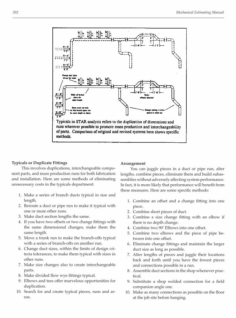
302 Mechanical Estimating Manual
Typicals or Duplicate Fittings This involves duplications, interchangeable compo-nent parts, and mass production runs for both fabrication and installation. Here are some methods of eliminating unnecessary costs in the typicals department:
1. Make a series of branch ducts typical in size and length.
2. Reroute a duct or pipe run to make it typical with one or more other runs.
3. Make duct section lengths the same. 4. If you have two offsets or two change fi ttings with
the same dimensional changes, make them the same length.
5. Move a trunk run to make the branch-offs typical with a series of branch-offs on another run.
6. Change duct sizes, within the limits of design cri-teria tolerances, to make them typical with sizes in other runs.
7. Make size changes also to create interchangeable parts.
8. Make divided fl ow wye fi ttings typical. 9. Elbows and tees offer marvelous opportunities for
duplication. 10. Search for and create typical pieces, runs and ar-
eas.
Arrangement You can juggle pieces in a duct or pipe run, alter lengths, combine pieces, eliminate them and build subas-semblies without adversely affecting system performance. In fact, it is more likely that performance will benefi t from these measures. Here are some specifi c methods:
1. Combine an offset and a change fi tting into one piece.
2. Combine short pieces of duct. 3. Combine a size change fi tting with an elbow if
there is no depth change. 4. Combine two 90’ Elbows into one offset. 5. Combine two elbows and the piece of pipe be-
tween into one offset. 6. Eliminate change fi ttings and maintain the larger
duct size as long as possible. 7. Alter lengths of pieces and juggle their locations
back and forth until you have the fewest pieces and connections possible in a run.
8. Assemble duct sections in the shop whenever prac-tical.
9. Substitute a shop welded connection for a fi eld companion angle one.
10. Make as many connections as possible on the fl oor at the job site before hanging.

Contracting for Profi t 303
Routing Direct routing and strategic placement and orienta-tion of equipment can be one of the major areas of cost reduction, not only for air distribution systems but piping and wiring systems as well.
The ultimate in effi ciency of routing, air distribu-tion, and equipment location is found in large single story discount stores with exposed duct runs. The air handling units are at the back of the store, their discharges facing the front. Ductwork is routed straight out of the units, directly across the store, with straight duct sections and only one or two change fi ttings. There are no turns or offsets. There is a grille at the end of the run to blow air on the front windows and a few grilles fl ush on both sides of the ductwork between there and the unit.
Skeptical though some may be, if the engineering is done correctly, the system achieves and maintains the objectives we are committed to. Physical comfort is pro-vided for customers and employees, air conditions are healthy and people can function as required. The cost of the ductwork in this case is approxi-mately 10 percent of the ventilation cost pie, not 30 or 40 percent as is the normal range. Here are specifi c methods and things to watch for in routing distribution and locating equipment:
1. Avoid loop routing wherever possible. 2. Avoid step routing. 3. Route directly at an angle instead of making
turns. 4. Combine parallel runs if possible. 5. Move a main run over ceiling outlets and eliminate
branches. 6. Move a main run closer to outlets to shorten
branches. 7. Route branches directly to outlets or terminals. 8. Route runs directly without offsets wherever pos-
sible. 9. Raise or lower criss-crossing ducts or reduce duct
depth to eliminate multiple offsets and elbows. 10. Avoid cramped or unnecessary criss-crossing by
rerouting. 11. Keep runs at the same elevation as much as pos-
sible. 12. Place mixing boxes between hot and cold trunk
runs to avoid criss-crossing branches and trunk runs.
13. Turn equipment so that duct or pipe connections are perpendicular to the runs they attach to, there-by eliminating turns. Provide straight shot orienta-tion.
14. Locate equipment at the same elevation as the duct or pipe runs, if possible, to avoid risers, offsets, turns, etc.

304 Mechanical Estimating Manual
Implement STAR as a Standard Procedure STAR can be implemented over and over. You will continually fi nd more and more unnecessary costs built into mechanical systems. The reasons for them are imma-terial; they’re there. And you’ll fi nd yourself and others through your effort-through using your imagination and creative abilities and through the valuable technique of simply looking.
ASHRAE Incorporates STAR Techniques Since these STAR techniques and principles were developed by Herb Wendes, and this article was origi-nally published in HPAC magazine in 1979, ASHRAE has incorporated many of the methods of cost reduction into their manuals.

305
Chapter 22
Computerized Estimating Principles
Wendes Systems, Inc. is pleased to announce two new powerful Windows based estimating systems that incorporate the principles and methodology described in this manual in an easy-to-use computerized software program. The systems are easy to learn and are ready to use with preloaded materials and labor. The WenDuct sheet metal estimating system is fast, accurate and easy-to-use with pre-loaded price and labor tables. A customizable database allows for maximum fl exibility. Computerized Takeoff incorporates fast digitizer technology, electronic pen, material templates and mouse driven point and click menus. The accurate Wendes method of estimating produces extensive reports and a bottom-line bid directly from the takeoff. The system is fl exible with user-defi nable square footage equations, customizable reports, tables and specifi cations for material and labor. Choose between a variety of duct types within a takeoff by selecting galvanized, spiral, industrial and fi berglass systems. After a takeoff is completed a system may be “value engineered” by comparing alternate duct types and materials. The software will automatically re-calculate an entire system based on alternate duct types and materials calculating new material and labor. The calculations for ductwork and fi tting are converted based on the aspect ratio of the original takeoff. WenDuct will automatically produce a detailed estimate by accepting the transfer of data from a wide range of Computer Aided Drafting and Detailing
Systems. An estimate may be easily produced based on the as drawn system vs. an original bid. Changes in job scope may be more accurately tracked and change orders produced. Data is available for viewing real time during takeoff, per selected item or system. The new WenPipe piping and plumbing estimating system includes an extensive 60,000 item database covering a wide range of HVAC, plumbing, piping, process and industrial materials. Computerized takeoff incorporates fast digitizer technology, electronic pen, material templates and mouse driven point and click menus. Accurate Labor is based on national labor or MCA labor available to registered MCA members. Extensive labor and material reports are produced directly from the takeoff. Harrison Pricing Services and Wendes Systems provide a seamless interface that links the estimating material database with updated Harrison pricing. Ferguson Enterprises, Inc. and Wendes Systems, Inc. have partnered to make Ferguson Commodity Pricing available to Ferguson customers. Ferguson Commodity Pricing is available directly through Ferguson Enterprises. Other pricing services are available for all North American Regions. For detailed information or to view the capability of computerized estimating contact the Wendes Systems, Inc. technical and training staff at 1-847-808-8371. Software is available on a free 30-day evaluation basis. On-line training is provided with evaluation software. Additional information is available on the Wendes Systems, Inc. web site: www.wendes.com.