mechanical four wheels steering
DESCRIPTION
my projectTRANSCRIPT

CHAPTER 1
INTRODUCTION TO AUTOMOBILE
An Automobile is a self–propelled vehicle which is used for the
transportation of passengers and goods upon the ground .A vehicle is a machine
which is used for the transportation of passengers and goods. A self propelled
vehicle is that in which power required for the propulsion is produced from
within. Aeroplane , ship motor boat ,locomotive ,car bus ,truck,
jeep ,tractor ,scooter ,motor cycle are the example of self propelled vehicles.
Motor vehicle is another name for the self propelled and used for the
transportation purposes upon the ground, so it differs from other types of self –
propelled vehicles. Like aeroplane, helicopter, rocket, ship, motor boat,
locomotive.
Automobile engineering is a branch of engineering in which we study all
about the automobile and have practice to propel them. The words “Automotive
Engineering” is also used having the same meaning.
Mobile or motive means one which can move. Automobile or automotive
means one which itself can move. A railway wagon cannot move itself on the
rails if it is not pushed or pulled by external force. A trolley cannot move itself
on the road if it is not pulled by external force. The railway wagon is pulled on
the rails by a locomotive. The trolley is pulled on the road by an automobile
which may be a jeep or tractor. In automobile engineering we study about the
self –propelled vehicles like car, bus, jeep, truck, tractor, scooter, motorcycle.
Aeronautical engineering deals with aeroplane, helicopter, rocket, etc., which
fly in air. Marine engineering deals with ship, motor, etc which sail in water.
1

1.1 TYPES OF AUTOMOBILES
The automobiles are classified on the following basis:
1. PURPOSE
i. Passenger vehicles – car, jeep, bus.
ii. Goods vehicles – Truck
2. CAPACITY
i. Light motor vehicles – car, jeep, motor cycle, and scooter.
ii. Heavy motor vehicles – Bus, coach, tractor.
3. FUEL USED
i. Petrol vehicles – car, jeep, motor cycle, scooter.
ii. Diesel vehicles – Truck, bus, tractor, bulldozer.
iii. Electric cab – Battery truck, fork lift.
iv. Steam carriages – Steam road roller.
4. No. Of wheels
i. Two wheelers.
ii. Three wheelers.
iii. Four wheelers.
iv. Six wheelers.
1.2 INTRODUCTION TO STEERING SYSTEM
The steering of a four wheel vehicle is, as far as possible, arranged so that
the front wheels will roll truly without any lateral slip. The front wheels are
supported on front axle so that they can swing to the left or right for steering.
This movement is produced by gearing and linkage between the steering wheel
2

in front of the driver and the steering knuckle or wheel. The complete
arrangement is called the steering system. The steering system essentially
consists of two elements- a steering gear at the lower end of the steering
knuckles and steering linkage .shows a simplified diagram of a steering system.
Fig 1.1 Steering System.
The function of the steering system is to convert the rotary
movement of the steering wheel into angular turn of the front wheels. The
steering systems also absorb a large part of the road shocks, thus preventing
them from being transmitted to the driver.
Fig 1.1 shows a late model of steering system. It has worm and roller type
steering gear and relay type steering linkage. When the driver turns the
steering wheel, the resulting motion is transmitted down a steering tube to
a steering gear set at the end of the steering tube. The gear set changes
the direction of motion, and multiplies the twisting force according to the gear
ratio. Its output shaft rotates to move the pinion arm which transmits the motion
of the steering knuckles through the relay road , idler arm , two tie rods , two
steering arm and the two front wheels. Thus as soon as the driver puts his hands
3

on the steering wheel the motion of the front wheels is in his hands. If he wants
to turns the vehicle to the left, he turns the steering wheel to the left, and if he
wants to turn the vehicle to the right, he turns steering wheel to the right,
otherwise the steering wheel is in its middle position and the vehicle is going in
a straight line.
1.3 REQUREMENTS OF STEERING SYSTEM
For the smooth performance of the system, the steering system of any
vehicle should fulfill the following requirements:
1. It should multiply the turning effort applied on the steering wheel by the
driver.
2. It should be to a certain degree irreversible so that the shocks of the road
surface encountered by the wheels are not transmitted to the driver’s
hand.
3. The mechanism should have self –rightening effect so that when the
driver release the steering wheel after negotiating the turn , the wheel
should try to achieve straight ahead position .
The readers may bear in mind that the requirements of any system may vary
but they should have some kind of average compromise.
1.4 FUNCTIONS OF THE STEERING SYSTEM
The various functions of the steering wheel are
1. To control the angular motion the wheels and thus the direction of motion of
the vehicle.
2. To provide directional stability of the vehicle while going straight ahead.
3. To facilitate straight ahead condition of the vehicle after completing a turn.
4. The road irregularities must be damped to the maximum possible extent.
This should co-exist with the road feel for the driver so that he can feel the
road condition without experiencing the effects of moving over it.
4

5. To minimize tyre wear and increase the life of the tyres.
1.5 TYPES OF STEERING
Depending on the number and position of the wheels being steered,
steering systems can be classified as follows:
1.5.1 Front wheel steering
The most commonly used type of steering, only the two front wheels of
the vehicle are used to steer the vehicle. This type of steering suffers from the
comparatively larger turning circle and the extra effort required by the driver to
negotiate the turn. A typical front wheel steering mechanism layout is given in
FIG 1.2.
1.5.2 Rear wheel steering
Some types of industry battery trucks and backhoe loaders use this type,
where only the two rear wheels control the steering. It can produced smaller
turning circles, but is unsuitable for high speed purposes and for ease of use.
FIG 1.2 - Conventional Front Wheel Steering System
5

1.5.3 Four wheel steering
The most effective type of steering, this type has all the four wheels of
the vehicle used for steering purpose. A detailed description of this type follows
FOUR WHEEL STEERING
In a typical front wheel steering system, the rear wheels do not turn in the
direction of the curve, and thus curb on the efficiency of the steering. Normally,
this system has not been the preferred choice due to the complexity of
conventional mechanical four wheel steering systems. However, a few cars like
the Honda Prelude, Nissan Skyline GT-R have been available with four wheel
steering systems, where the rear wheels turn by a small angle to aid the front
wheels in steering. However, these systems had the rear wheels steered by only
2 or 3 degrees, as their main aim was to assist the front wheels rather than steer
by themselves.
With advances in technology, modern four wheel steering systems boast
of fully electronic steer-by-wire systems, equal steer angles for front and rear
wheels, and sensors to monitor the vehicle dynamics and adjust the steer angles
in real time. Although such a complex 4WS model has not been created for
production purposes, a number of experimental concepts with some of these
technologies have been built and tested successfully.
Compared with a conventional two wheel steering system, the advantages
offered by a 4WS system include:
1. Superior cornering stability.
2. Improved steering responsiveness and precision. High speed straight line
stability.
3. Notable improvement in rapid lane-changing maneuvers.
4. Smaller turning radius and tight-space maneuverability at low speed.
5. Relative Wheel Angles and their Control.
6

The direction of steering the rear wheels relative to the front wheels
depends on the operating conditions. At low-speed wheel movement is
pronounced, so that rear wheels are steered in the opposite direction to that of
front wheels. This also simplifies the positioning of the car in situations such as
parking in a confined space. Since the rear wheels are made to follow the path
on the road taken by the front wheels, the rear of a 4WS car does not turn in the
normal way. Therefore the risk of hitting an obstacle is greatly reduced.
At high speed, when steering adjustments are subtle, the front wheels and
rear wheels turn in the same direction. As a result, the car moves in a crab-like
manner rather than in a curved path. This action is advantageous to the car
while changing lanes on a high-speed road. The elimination of the centrifugal
effect and, in consequence the reduction of body roll and cornering force on the
tyre, improves the stability of the car so that control becomes easier and safer.
In a 4WS system, the control of drive angle at front and rear wheels is most
essential.
Fig1.3 Four Wheel Steering System
7

1.6 TWO MODES ARE GENERALLY USED IN THESE 4WS
MODELS:
1.6.1 Slow Speeds - Rear Steer Mode:
At slow speeds, the rear wheels turn in the direction opposite to the front
wheels. This mode comes in particularly useful in case of pickup trucks and
buses, more so when navigating hilly regions. It can reduce the turning circle
radius by 25%, and can be equally effective in congested city conditions, where
U-turns and tight streets are made easier to navigate. It is described as following
in FIG 1.4.
FIG 1.4 - Rear Steer Mode
1.6.2 High Speeds:
In high speeds, turning the rear wheels through an angle opposite to front
wheels might lead to vehicle instability and is thus unsuitable. Hence, at speeds
above 80 kmph, the rear wheels are turned in the same direction of front wheels
in four-wheel steering systems. This is shown in FIG 1.5
FIG 1.5 - Crab Mode
8

The front-to-rear steering ratio variation with respect to vehicle speed is
defined by the following FIG 1.6
FIG 1.6 - Front-Rear Steering Ratio with respect to speed
For a typical vehicle, the vehicle speed determining the change of phase
has been found to be 80 km/hr. The steering ratio, however, can be changed
depending on the effectiveness of the rear steering mechanism, and can be as
high as 1:1.
1.6.3 ZERO TURNING CIRCLE RADIUS - 360 MODE
In addition to the aforementioned steering types, a new type of four-
wheel steering was introduced by the concept vehicle Jeep Hurricane, one that
could significantly affect the way our vehicles are parked in the future. Its
shown in the following FIG 1.7
FIG 1.7 - The Jeep Hurricane concept with Zero Turning Circle Radius
9

This vehicle has all the three modes of steering described above, though it
sports a truly complex drive-train and steering layout with two transfer cases to
drive the left and right wheels separately. The four wheels have fully
independent steering and need to turn in an unconventional direction to ensure
that the vehicle turns around on its own axis. Such a system requires precise
calculation from a servo motor with real-time feedback to make certain that all
three steering modes function perfectly. The concept didn’t make it to
production, possibly due to the high costs involved in the power train layout.
But the idea presented by the concept continues to find importance. The only
major problem posed by this layout is that a conventional rack-and-pinion
steering with pitman arms would not be suitable for this mode, since the two
front wheels are steered in opposite directions. Steer-by-wire systems would
work fine, however, since independent control can be achieved.
10

CHAPTER 2
REVIEW OF LITEREATURE
2.1 HONDA 4WS SYSTEM
This system is dependent on the steer angle so that the movement of the
rear wheels is controlled by the angular movement of the front wheels. For
steering of the front wheels up to about 130 degrees, the rear wheels are so
arranged that they turn through a small angle in the same direction as the front
wheels. Beyond this angle, the rear wheels gradually straighten up and then turn
through a comparatively large angle in the opposite direction (Fig. 2.2).
An Epicyclic gear mechanism incorporated in the rear steering gearbox
controls the rear wheels angles. A fixed annulus is meshed with a large planet
gear, which is driven by an eccentric on the input shaft. A short shaft in integral
with the planet and is offset from the centre of the planet. This shaft transmits a
drive through a slider and guide to a stroke rod, connected to the rear wheel
track rods (Fig. 2.1 A).
Slight movement of the input shaft rotates the planet which in turn moves
the offset output shaft slightly in the same direction as the input (Fig.2.1 B). As
the input shaft moves the offset shaft towards the TDC position (Fig. 2.1 C), the
stroke rod rotates back to the central position so that the rear wheels are set in a
straight ahead position.
As the input shaft and planet are rotated towards the full-lock position
(Fig. 2.1D), the stroke rod attains maximum displacement and consequently a
corresponding movement of the rear wheels takes place. The rear gearbox is
maintenance free and is greased for its entire life. The centre shaft couplings
have splines to both steering gearboxes. A master spline at each connected point
ensures correct assembly of the units.
11

Fig. 2.1. Epicyclic Gear Action (Honda).
Fig. 2.2. Epicyclic Gear Action (Honda).
2.2 MAZDA 4WS SYSTEM
The rear wheels in this system are steered by a hydraulically operated
power unit, which is electronically controlled in accordance with the steering
wheel angle and vehicle speed. The Mazda 4WS layout is more complicated
than the Honda arrangement and hence incorporates suitable fail-safe for trouble
12

free operation. The fail-safe device includes a centering lock spring and special
safety solenoid. If hydraulic or electronic failure takes place, these devices set
the rear wheels to the straight-ahead position.
Two electronic sensors, installed at transmission output and speedometer
drive, measure the vehicle speed. The signals are passed to the built-in memory
of an electronic control unit (ECU), which commands the hydraulic system for
setting the direction and angle for the rear wheels. For speeds less than 35
kmph, the rear wheels are steered in the opposite direction to that of the front
wheels. As 35 kmph is approached, the rear wheels are turned to the straight-
ahead position. Above this speed the rear wheels are steered in the same
direction as the front wheels with an angle limited to 5 degrees.
Fig. 2.3. Schematic Layout of Rear-Wheel Steer Unit (Mazda).
Figure 2.3 represents the schematic of the system and indicates the main
components used in this system. The functions of these components in steering
the rear wheels are as follows:
1. Sensors to measure vehicle speed.
13

2. Steering phase control unit conveys to the hydraulic control valve the
required stroke direction of movement. (Hi) Electric stepper motor alters
the yoke angle and bevel gear phasing in accordance with the signals
received from the ECU.
3. Rear steering shaft provides the position of the front wheels to the bevel
gear in the steering phase control unit.
4. Control valve controls the hydraulic pressure supplied to the ram
cylinder.
5. Hydraulic ram cylinder steers the rear wheels depending upon the
requirements.
Fig. 2.4. Steering Phase Control Unit.
The steering phase control unit (Fig. 2.4) alters the direction and angle of
the rear wheels. The electrical pulses from the ECU to the stepper motor, and
the movement from the steering shaft to the bevel gear, alter the position of the
hydraulic control valve to suit the conditions.
14

CHAPTER 3
STEERING SYSTEM
3.1 ACKERMAN STEERING MECHANISM
Shown in FIG 3.1, Ackermann steering geometry is a geometric
arrangement of linkages in the steering of a car or other vehicle designed to
solve the problem of wheels on the inside and outside of a turn needing to trace
out circles of different radii. The steering pivot points are joined by a rigid bar
called the tie rod which is also a part of the steering mechanism. With perfect
Ackermann, at any angle of steering, the centre point of all of the circles traced
by all wheels will lie at a common point. But this may be difficult to arrange in
practice with simple linkages, and designers draw or analyze their steering
systems over the full range of steering angles. Hence, modern cars do not use
pure Ackermann steering, partly because it ignores important dynamic and
compliant effects, but the principle is sound for low speed maneuvers, and the
right and left wheels do not turn by the same angle, be it any cornering speed.
This presents a difficult problem for vehicles with independent steering,
as the wheels cannot be easily given the correct Ackerman turning angles. This
would directly affect the dynamic handling of the car, making it impossible to
control properly. With all the four wheels steered, the problem gets
compounded, since the appropriate steering angles for all four wheels need to be
calculated. It is to be noted that the variation in steering angles as a result of
Ackerman geometry is progressive and not fixed, hence they have to be pre-
calculated and stored by the controller. This dictates that the control of four-
wheel steering systems be very precise, and consequently, complex. This is
another reason why manufacturers have not preferred the use of such systems in
their vehicles, even with recent advances in technology. The cost of such
systems can be high, and a good amount of research & development is required
upfront.
15

FIG 3.1 - Ackerman Steering Geometry
Nevertheless, the benefits that engineers can reap out of this technology are
significant enough to work around these obstacles.
We chose to use a simple control circuit to demonstrate the
effectiveness of a four wheel steering system, and at the same time,
simulated the suspension-steering assembly of a typical car to predict the
Ackerman angles for corresponding steer angles.
S.NO Troubles Causes
1. Hard steering (a) Low type pressure
(b)Too tight steering gear.
(c) Binding steering linkage.
(d) Incorrect or insufficient lubrication.
(e) Incorrect caster, camber, king pin
inclination or toe- in.
(f) Bent or broken steering arms,
16

knuckles or suspension arms.
(g)Weak or sagging front springs.
(h)Bent or broken frame.
(i) Bent steering shaft.
(j) Too tight spherical ball joints.
2.
Excessive play or
looseness in the steering
system
(a) Loose or worm steering.
(b)Loose or worm steering gear.
(c) Worm kingpins, steering knuckle
bushing, bearings or spherical joints.
(d)Loose steering gear housing on frame
or cross member.
(e) Loose steering wheel on post.
(f) Loose or worm steering gear flexible
coupling.
3.Erratic steering when
brakes are applied.
(a) Poorly adjusted brakes.
(b)Worm brake lining.
(c) Insufficient or uneven caster.
(d)Bent steering knuckle and 1 (a),1 (g)
4. Car wanders.
(a) Bent steering knuckle.
(b)Shifted rear axes housing.
(c) Inoperative stabilizer.
(d)Too tight king pin , bushings
5. Shimmy front wheels
(a) Unbalance wheels.
(b)Wheels or tyres out of true.
(c) Inoperative shock absorbers
(d) Incorrect toe-in
(e) Eccentric or bulged tyres
17

6.
Front wheels tramp
(wheels move up and
down and separately).
(a) Eccentric wheels or tyres , and
4(c),5(a,b,c)
7.Car pulls continuously to
one side.
(a) Rear wheels not tracking with front
wheel bearing.
(b)Too tight wheel
(c) Loose mounting bolts of suspension
arm and 1 (a ,e, g, h ) 3 ( a, b , d ,) 4
(b) and 5 (c)
8.Poor turn of gear to centre
after turning.(a) Blinding or sticking control valve
or actuator lever.
9.Steering wheel jerks
when turning.(a) Loose pump belt.
Table 3.1: Steering Troubles and Their Causes.
3.2 STEERING RATIOS
Every vehicle has a steering ratio inherent in the design. If it didn't you'd
never be able to turn the wheels. Steering ratio gives mechanical advantage to
the driver, allowing you to turn the tyres with the weight of the whole car sitting
on them, but more importantly, it means you don't have to turn the steering
wheel a ridiculous number of times to get the wheels to move. Steering ratio is
the ratio of the number of degrees turned at the steering wheel vs. the number of
degrees the front wheels are deflected. So for example, if you turn the steering
wheel 20° and the front wheels only turn 1° that gives a steering ratio of 20:1.
For most modern cars, the steering ratio is between 12:1 and 20:1. This coupled
with the maximum angle of deflection of the wheels gives the lock-to-lock turns
18

for the steering wheel. For example, if a car has a steering ratio of 18:1 and the
front wheels have a maximum deflection of 25°, then at 25°, the steering wheel
has turned 25°x18, which is 450°. That's only to one side, so the entire steering
goes from -25° to plus 25° giving a lock-to-lock angle at the steering wheel of
900°, or 2.5 turns (900° / 360).
This works the other way around too of course. If you know the lock-to-
lock turns and the steering ratio, you can figure out the wheel deflection. For
example if a car is advertised as having a 16:1 steering ratio and 3 turns lock-to-
lock, then the steering wheel can turn 1.5x360° (540°) each way. At a ratio of
16:1 that means the front wheels deflect by 33.75° each way.
For racing cars, the steering ratio is normally much smaller than for
passenger cars - ie. Closer to 1:1 - as the racing drivers need to get fuller
deflection into the steering as quickly as possible.
Table 3.2 Comparative Steering Data of Some Indian Automobiles.
19

3.3 TURNING CIRCLES
The turning circle of a car is the diameter of the circle described by the
outside wheels when turning on full lock. There is no hard and fast formula to
calculate the turning circle but you can get close by using this:
Turning circle radius = (track/2) + (wheelbase/sin (average steer angle))
The numbers required to calculate the turning circle explain why a classic
black London taxi has a tiny 8m turning circle to allow it to do U-turns in the
narrow London streets. In this case, the wheelbase and track aren't radically
different to any other car, but the average steering angle is huge. For
comparison, a typical passenger car turning circle is normally between 11m and
13m with SUV turning circles going out as much as 15m to 17m.
S.No Company Name Steering wheel radius in cm
1 Ambassador 43.2
2 Willy Jeep 43.8
3 Premier car 43
4 Standard – 10 car 39
5 Maruti – 800 car 37
Table: 3.2 Steering wheel radius of some of the light vehicles manufactured in
India:
20

3.4 KING PIN AND KING PIN AXIS:
The imaginary axis about which the steered wheels are swivelled. In
older models a solid structural component is used a s a king pin and its center
line is the king pin axis. In present day models the solid component is absent.
Instead ball joints are used. The imaginary line joining upper and lower ball
joint acts as king pin axis.
Fig 3.2 King Pin Axis
3.5 King-pin inclination or steering axle inclination
The angle between the vertical line and centre of the king pin or steering
axle, when viewed from the front of the vehicle is known as king pin inclination
or steering axle inclination. The king pin inclination, in combination with caster,
is used to provide directional stability in modern cars, by tending to return the
wheels to the straight – ahead position after any turn. It also reduces steering
effort particularly when the vehicle is stationary. It reduces tyre wear also. The
king pin inclination in modern vehicle range from 4 to 8 degree .It must be
equal on both the sides. If it is greater on one side than the other, the vehicle
21

will tend to pull to the side having the greater angle. Also, if the angle is too
large, the steering will become exceedingly difficult. The king-pin inclination is
made adjustable only by bending.(fig 3.3)
Fig 3.3 King Pin Angle
3.6 CENTER POINT STEERING:
When center line of the wheel meets the center line of the king pin axis at
the road surface it is called center point steering.
3.6.1 Disadvantages of not having center point steering:
1. Unnecessary couple formed due to forces of vertical weight and road
resistance separated by a distance.
22

2. Steering becomes heavy as the wheel movement is along an arc of radius
equal to the distance between king pin axis projection and tyre contact
point.
3. Large bending stresses in steering components.
3.7 SCRUB RADIUS:
The distance between the center line of the wheel and the king pin axis at
the road surface.
3.7.1 Positive scrub radius: When king pin axis meets the road inside the tyre
tread line.
3.7.2 Negative scrub radius: When king pin axis meets the road outside the
tyre tread line.
Fig 3.4 Scrub Radius
23

3.8 FRONT WHEEL GEOMETRY:
Fig 3.5 Wheel Geometry
3.8.1 CASTOR:
In addition to being tilted inward toward the centre of the vehicle, the
kingpin axis may also be tilted forward or backward from the vertical line. This
tilt is known as caster. Thus the angle between the vertical line and the kingpin
centre line in the plane of the wheel (when viewed from the side) is called caster
angle. When the top of the king pin is backward, the caster angle is positive, and
when it is forward the caster angle is negative .the caster angle in modern
vehicles ranges from 2 to 8 degree.
Tilt of the king pin axis from the vertical either towards the front
(negative castor) or towards the rear (positive castor)
24

Castor gives directional stability: The force acting at the pivot (steering axis)
and the resistance at the surface constitute a couple so that the wheel follows the
line of thrust.
Fig3.6 Caster
3.8.2 CAMBER:
The angle between the centre line of the tyre and the vertical line when
viewed from the front of the vehicle is known as camber. When the angle is
outward, so that the wheels are farther apart at the top than at the bottom, the
camber is positive. When the angle is inward, so that the wheels are closer
together at the top than at the bottom, positive or negative, tends to cause
uneven or move tyre wear on side than on the other side. Camber should not
exceed to 2°.
25

Positive camber: When upper part of wheel is outside.
Negative camber: When upper part of wheel is inside (towards the center line
of the car)
Reason to include camber:
To adjust for road camber.
To compensate for the deflections in the axle under full load of a vehicle
resulting in negative camber of the wheel.
To compensate for king pin inclination.
Fig 3.7 Camber
26

3.8.3 TOE IN:
Fig 3.8 Toe In
The front wheels are usually turned in slightly in front so that the distance
between the front ends (a) is slightly less than the distance between the back
ends (b), when viewed from the top. The difference between these distances is
called toe in. On a car with toe – in, the distance between the front wheels is
less at the front (a) than at the rear (b), when viewed from the top. The amount
of toe-in is usually 3 to 5 mm. The toe –in is provided to ensure parallel rolling
of the front wheels, to stabilize steering and prevent side slipping and excessive
tyre wear. It also serves to offset the small deflections in the wheel-support
system which comes out when the car is standing still; they tend to roll parallel
on the road when the car is moving forward. Some alignment specialists set the
front wheels in “straight-away alignment” in preference to “toe-in adjustment”.
27

3.8.4 TOE OUT:
Fig 3.9 Toe-Out
Toe-out is the difference in angles between the two front wheels and the
car frame during turns. The steering system is designed to turn the inside wheel
through a larger angle than the outside wheel when making a turn. This
condition causes the wheels to toe-out on turns, due to the difference in their
turning angles. When the car is taking turn, the outer wheels rolls on a larger
radius than the inner wheel, and the circles on which the two front wheels must
roll are concentric. Therefore the inner wheel must make a larger angle with the
car frame than that the outer wheel makes. As shown in figure ,when the front
wheels are steered to make a turn the , inner wheels turns to an angle of 23°
with the car frame , while the outer wheel turns only 20° with the car frame .
28

The toe –out is secured by providing the proper relationship between the
steering knuckle arms, tie rods and pitman arm.
Fig 3.10 Toe-Out (Detailed)
Reason for toe in and Toe out:
To compensate for movement within steering ball joints,
suspension linkages, etc.
In motion the toe in / toe out leads to parallel tyres.
Toe – in neutralises cone running due to camber and hence
dependent on camber.
29

CHAPTER 4
VEHICLE DYNAMICS AND STEERING
4.1 Understeer:
Understeer is so called because when the slip angle of front wheels is
greater than slip angle of rear wheels. Understeer can be brought on by all
manner of chassis, suspension and speed issues but essentially it means that the
car is losing grip on the front wheels. Typically it happens as you brake and the
weight is transferred to the front of the car. At this point the mechanical grip of
the front tyres can simply be overpowered and they start to lose grip (for
example on a wet or greasy road surface). The end result is that the car will start
to take the corner very wide. In racing, that normally involves going off the
outside of the corner into a catch area or on to the grass. In normal you-and-me
driving, it means crashing at the outside of the corner. Getting out of understeer
can involve letting off the throttle in front-wheel-drive vehicles (to try to give
the tyres chance to grip) or getting on the throttle in rear-wheel-drive vehicles
(to try to bring the back end around).
Fig 4.1 Under Steer
30

4.2 Oversteer:
Over steer is defined when the slip angle of front wheels lesser than the slip
angle of rear wheels. With oversteer, the car goes where it's pointed far too
efficiently and you end up diving into the corner much more quickly than you
had expected. Oversteer is brought on by the car losing grip on the rear wheels
as the weight is transferred off them under braking, resulting in the rear kicking
out in the corner. Without counter-steering (see Fig ) the end result in racing is
that the car will spin and end up going off the inside of the corner backwards. In
normal you-and-me driving, it means spinning the car and ending up pointing
back the way you came.
Fig 4.2 Over Steer
4.3 Neutral steer or counter steering:
Counter-steering can defined as when the slip angle of front wheels is
equal to slip angle of rear wheels is what you need to do when you start to
experience oversteer. If you get into a situation where the back end of the car
loses grip and starts to swing out, steering opposite to the direction of the corner
31

can often 'catch' the oversteer by directing the nose of the car out of the corner.
In drift racing and demonstration driving, it's how the drivers are able to smoke
the rear tyres and power-slide around a corner. They will use a combination of
throttle, weight transfer and handbrake to induce oversteer into a corner, then
flick the steering the opposite direction, honk on the accelerator and try to hold
a slide all the way around the corner. It's also a widely-used technique in rally
racing.
Fig 4.3 Counter Steering
32

CHAPTER 5
STEERING GEAR BOXES
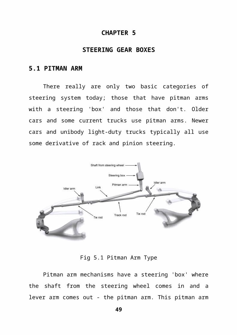
5.1 PITMAN ARM
There really are only two basic categories of steering system today; those
that have pitman arms with a steering 'box' and those that don't. Older cars and
some current trucks use pitman arms. Newer cars and unibody light-duty trucks
typically all use some derivative of rack and pinion steering.
Fig 5.1 Pitman Arm Type
Pitman arm mechanisms have a steering 'box' where the shaft from the
steering wheel comes in and a lever arm comes out - the pitman arm. This
pitman arm is linked to the track rod or centre link, which is supported by idler
arms. The tie rods connect to the track rod. There are a large number of
variations of the actual mechanical linkage from direct-link where the pitman
arm is connected directly to the track rod, to compound linkages where it is
connected to one end of the steering system or the track rod via other rods. The
example below shows a compound link. 33

Most of the steering box mechanisms that drive the pitman arm have a
'dead spot' in the centre of the steering where you can turn the steering wheel a
slight amount before the front wheels start to turn. This slack can normally be
adjusted with a screw mechanism but it can't ever be eliminated. The traditional
advantage of these systems is that they give bigger mechanical advantage and
thus work well on heavier vehicles. With the advent of power steering, that has
become a moot point and the steering system design is now more to do with
mechanical design, price and weight. The following are the four basic types of
steering box used in pitman arm systems.
5.2 RACK AND PINION:
This is by far the most common type of steering you'll find in any car
today due to its relative simplicity and low cost. Rack and pinion systems give a
much better feel for the driver, and there isn't the slop or slack associated with
steering box pitman arm type systems. The downside is that unlike those
systems, rack and pinion designs have no adjustability in them, so once they
wear beyond a certain mechanical tolerance, they need replacing completely.
This is rare though.
In a rack and pinion system, the track rod is replaced with the steering
rack which is a long, toothed bar with the tie rods attached to each end. On the
end of the steering shaft there is a simple pinion gear that meshes with the rack.
When you turn the steering wheel, the pinion gear turns, and move the rack
from left to right. Changing the size of the pinion gear alters the steering ratio. It
really is that simple. The diagrams here show an example rack and pinion
system (left) as well as a close-up cutaway of the steering rack itself (right).
34

Fig 5.2 Rack and Pinion Type.
Fig 5.3 Rack and Pinion.
35

5.2.1 Variable-Ratio Rack and Pinion Steering
This is a simple variation on the above design. All the components are the
same, and it all works the same except that the spacing of the teeth on the rack
varies depending on how close to the centre of the rack they are. In the middle,
the teeth are spaced close together to give slight steering for the first part of the
turn - good for not over steering at speed. As the teeth get further away from the
centre, they increase in spacing slightly so that the wheels turn more for the
same turn of the steering wheel towards full lock.
5.3 RECIRCULATING BALL RACK AND SECTOR:
Fig 5.4 Recirculating Ball Rack and Sector.
This is by far the most common type of steering box for pitman arm
systems. In a recirculating ball steering box, the worm drive has many more
turns on it with a finer pitch. A box or nut is clamped over the worm drive that
contains dozens of ball bearings. These loop around the worm drive and then
out into a recirculating channel within the nut where they are fed back into the
36

worm drive again. As the steering wheel is turned, the worm drives turns and
forces the ball bearings to press against the channel inside the nut. This forces
the nut to move along the worm drive. The nut itself has a couple of gear teeth
cast into the outside of it and these mesh with the teeth on a sector gear which is
attached to the cross shaft just like in the worm and sector mechanism. This
system has much less free play or slack in it than the other designs, hence why
it's used the most. The example below shows a recirculating ball mechanism
with the nut shown in cutaway so you can see the ball bearings and the
recirculation channel.
5.4 WORM AND SECTOR:
Fig 5.5 Worm and Sector.
In this type of steering box, the end of the shaft from the steering wheel
has a worm gear attached to it. It meshes directly with a sector gear (so called
because it's a section of a full gear wheel). When the steering wheel is turned,
the shaft turns the worm gear, and the sector gear pivots around its axis as its
teeth are moved along the worm gear. The sector gear is mounted on the cross
37

shaft which passes through the steering box and out the bottom where it is
splined, and the the pitman arm is attached to the splines. When the sector gear
turns, it turns the cross shaft, which turns the pitman arm, giving the output
motion that is fed into the mechanical linkage on the track rod. The following
diagram shows the active components that are present inside the worm and
sector steering box. The box itself is sealed and filled with grease.
5.5 WORM AND ROLLER:
Fig 5.6 Worm and Roller.
The worm and roller steering box is similar in design to the worm and
sector box. The difference here is that instead of having a sector gear that
meshes with the worm gear, there is a roller instead. The roller is mounted on a
roller bearing shaft and is held captive on the end of the cross shaft. As the
worm gear turns, the roller is forced to move along it but because it is held
captive on the cross shaft, it twists the cross shaft. Typically in these designs,
the worm gear is actually an hourglass shape so that it is wider at the ends.
38

Without the hourglass shape, the roller might disengage from it at the extents of
its travel.
5.6 CAM AND ROLLER:
Fig 5.7 Cam and Roller
Cam and lever steering boxes are very similar to worm and sector
steering boxes. The worm drive is known as a cam and has a much shallower
pitch and the sector gear is replaced with two studs that sit in the cam channels.
As the worm gear is turned, the studs slide along the cam channels which forces
the cross shaft to rotate, turning the pitman arm. One of the design features of
this style is that it turns the cross shaft 90° to the normal so it exits through the
side of the steering box instead of the bottom. This can result in a very compact
design when necessary.
39

CHAPTER 6
TYPES OF 4WS
There are three types of production of four-wheel steering systems:
i. Mechanical 4WS
ii. Hydraulic 4WS
iii. Electro-hydraulic 4WS
6.1 Mechanical 4WS
Fig 6.1 Mechanical 4WS.
40

In a straight-mechanical type of 4WS, two steering gears are used-one for
the front and the other for the rear wheels. A steel shaft connects the two
steering gearboxes and terminates at an eccentric shaft that is fitted with an
offset pin. This pin engages a second offset pin that fits into a planetary gear.
The planetary gear meshes with the matching teeth of an internal gear that
is secured in a fixed position to the gearbox housing. This means that the
planetary gear can rotate but the internal gear cannot. The eccentric pin of the
planetary gear fits into a hole in a slider for the steering gear.
A 120-degree turn of the steering wheel rotates the planetary gear to
move the slider in the same direction that the front wheels are headed.
Proportionately, the rear wheels turn the steering wheel about 1.5 to 10 degrees.
Further rotation of the steering wheel, past the 120degree point, causes the rear
wheels to start straightening out due to the double-crank action (two eccentric
pins) and rotation of the planetary gear. Turning the steering wheel to a greater
angle, about 230 degrees, finds the rear wheels in a neutral position regarding
the front wheels. Further rotation of the steering wheel results in the rear wheels
going counter phase with regard to the front wheels. About 5.3 degrees
maximum counter phase rear steering is possible.
Mechanical 4WS is steering angle sensitive. It is not sensitive to vehicle
road speed.
41

6.2 Hydraulic 4WS
Fig 6.2 Hydraulic 4WS
The hydraulically operated four-wheel-steering system is a simple design,
both in components and operation. The rear wheels turn only in the same
direction as the front wheels. They also turn no more than 11/2 degrees. The
42

system only activates at speeds above 30 mph (50 km/h) and does not operate
when the vehicle moves in reverse.
A two-way hydraulic cylinder mounted on the rear stub frame turn the
wheels. Fluid for this cylinder is supplied by a rear steering pump that is driven
by the differential. The pump only operates when the front wheels are turning.
A tank in the engine compartment supplies the rear steering pump with fluid.
When the steering wheel is turned, the front steering pump sends fluid
under pressure to the rotary valve in the front rack and pinion unit. This forces
fluid into the front power cylinder, and the front wheels turn in the direction
steered. The fluid pressure varies with the turning of the steering wheel. The
faster and farther the steering wheel is turned, the greater the fluid pressure.
The fluid is also fed under the same pressure to the control valve where it
opens a spool valve in the control valve housing. As the spool valve moves, it
allows fluid from the rear steering pump to move through and operate the rear
power cylinder. The higher the pressure on the spool, the farther it moves. The
farther it moves, the more fluid it allows through to move the rear wheels. As
mentioned earlier, this system limits rear wheel movement to 11/2 degrees in
either the left or right direction.
43

6.3 Electro-hydraulic 4WS
Fig 6.1 Electro-Hydraulic 4WS
Several 4WS systems combine computer electronic controls with
hydraulics to make the system sensitive to both steering angle and road speeds.
In this design, a speed sensor and steering wheel angle sensor feed information
to the electronic control unit (ECU). By processing the information received,
the ECU commands the hydraulic system steer the rear wheels. At low road
speed, the rear wheels of this system are not considered a dynamic factor in the
steering process.
44

At moderate road speeds, the rear wheels are steered momentarily counter
phase, through neutral, then in phase with the front wheels. At high road speeds,
the rear wheels turns only in phase with the front wheels. The ECU must know
not only road speed, but also how much and quickly the steering wheel is
turned. These three factors - road speed, amount of steering wheel turn, and the
quickness of the steering wheel turn - are interpreted by the ECU to maintain
continuous and desired steer angle of the rear wheels.
The basic working elements of the design of an electro-hydraulic 4WS
are control unit, a stepper motor, a swing arm, a set of bevelled gears, a control
rod, and a control valve with an output rod. Two electronic sensors tell the ECU
how fast the car is going.
The yoke is a major mechanical component of this electro-hydraulic
design. The position of the control yoke varies with vehicle road speed. For
example, at speeds below 33 mph (53 km/h), the yoke is in its downward
position, which results in the rear wheels steering in the counter phase (opposite
front wheels) direction. As road speeds approach and exceed 33 mph (53 km/h),
the control yoke swings up through a neutral (horizontal) position to an up
position. In the neutral position, the rear wheels steer in phase with the front
wheels.
The stepper motor moves the control yoke. A swing arm is attached to the
control yoke. The position of the yoke determines the arc of the swing rod. The
arc of the swing arm is transmitted through a control arm that passes through a
large bevel gear. Stepper motor action eventually causes a push-or-pull
movement of its output shaft to steer the rear wheels up to a maximum of 5
degrees in either direction.
The electronically controlled, 4WS system regulates the angle and
direction of the rear wheels in response to speed and driver's steering. This
45

speed-sensing system optimizes the vehicle's dynamic characteristics at any
speed, thereby producing enhanced stability and, within certain parameters.
6.4 ACTUAL 4WS
The actual 4WS system consists of a rack and pinion front steering that is
hydraulically powered by a main twin-tandem pump. The system also has a
rear-steering mechanism, hydraulically powered by the main pump. The rear-
steering shaft extends from the rack bar of the front-steering assembly to the
rear-steering-phase control unit.
The rear steering is comprised of the input end of the rear-steering shaft,
vehicle speed sensors, and steering-phase control unit (deciding direction and
degree), a power cylinder, and an output rod. A centering lock spring is
incorporated that locks the rear system in a neutral (straight-ahead) position in
the event of hydraulic failure. Additionally, a solenoid valve that disengages the
hydraulic boost (thereby activating the centering lock spring in case of an
electrical failure) is included.
46

CHAPTER 7
CHARACTERISTICS OF WHEEL CHAIR DRIVE
CONFIGURATIONS
The ability of the user to maneuver a powered wheelchair in confined
spaces is closely related to the wheelchair's drive and steering configurations.
The most common drive configuration, differential rear-wheel drive, consists of
fixed and driven rear wheels with front caster wheels. Direction changes are
made by individually varying the speeds of the rear wheels. In this
configuration, the point about which the wheelchair pivots lies on a line
perpendicular to, and running through, the center of the rear wheels. The
minimum turning radius is achieved when the pivot point is located at the
midpoint between the rear wheels. The minimum space required to turn the
wheelchair is then determined by the maximum distance from that point to any
other point on the wheelchair, usually the front corner of the base or the user's
feet hanging off the front of the chair. A similar analysis applies to drive
configurations with fixed and differentially driven front wheels and rear caster
wheels. The fixed rear wheel and caster front wheel drive configuration is
illustrated in Fig 7.1.
To minimize the turning radius for the fixed-wheel, differential-drive
configuration, the fixed-drive wheels must be located as close as possible to the
geometric center of the chair. For fixed front-wheel-drive chairs, the drive
wheels are moved rearward, and for fixed rear-wheel-drive chairs, the rear
wheels are moved forward. Another benefit of locating the drive wheels close to
the geometric center of the chair is that a larger portion of the total weight of the
wheelchair is borne by the drive wheels and less by the caster wheels.
47

Fig 7.1 Fixed Rear-Wheel Differential Drive Configurations.
The greater the weight borne by the caster wheels, the more difficult it is
to change directions when caster wheels must reverse directions and rotate
through 180°. The approach, however, causes the designer to take extraordinary
steps to provide stability. Typically, stability is achieved by counterbalancing
the user's mass over and in front of the main drive wheels with the mass of the
batteries behind the main drive wheels. It may be necessary to provide caster or
sprung wheels in the rear of the chair to avoid tipping backward while
accelerating forward. The addition of these extra wheels, if small, may also
compromise the chair's ability to climb low obstacles.
An alternate approach to minimizing the turning radius is to steer all four
wheels; this avoids the problems associated with caster wheels, yet retains
minimum turning radius and maximizes stability. Added benefits of four-wheel
steering are the tracking of front and rear wheels along the same path and
enhanced obstacle climbing capability.
The challenge in designing a mechanical four-wheel steering mechanism is to
design a device with the ability to turn each wheel through 180° while
minimizing Ackerman errors (misalignment of the wheels). Ackerman steering
48
linkages, such as those used in automobiles, owe their simple design to the
relatively small turning angles required by that type of vehicle. For highly
maneuverable wheelchairs, the range of steering angle is much greater, and the
wheels must maintain proper alignment over that entire range to avoid
undesirable scrubbing when the wheelchair moves. Scrubbing results in
excessive tire wear, wrinkling of carpets, and/or undesirable tire noise.
The wheels are properly aligned whenever lines projected from the axis of
each intersect at a single point. In four-wheel steering configured for minimum
turning radius, this point lies on a line between the front and rear wheels
running perpendicular to the fore-aft direction of the base, as illustrated in
Fig.7.2 In two-wheel steering, the perpendicular bisectors of the front steered
wheels intersect at a point along the line through the centers of the fixed rear
wheels.
Fig 7.2 Wheel alignment for four-wheel steering about a single pivot point.
Another significant advantage of four-wheel steering over two-wheel
differentially driven and two-wheel steering is that in the four-wheel
configuration, the rear wheels track the front wheels. This is not the case when
either the front or rear wheels are fixed. What this means to the user is that
when the front of the wheelchair clears a corner, the rear will also clear, if
49

course direction is not changed. The problem is analogous to that facing
automobile drivers when they attempt to enter a parking space head in between
two other cars, or the one tractor trailer drivers have making turns at right angle
intersections. In both situations, the drivers are required to make course
corrections during the maneuver to avoid collisions with the obstacles on the
inside of the turn. In other words, course corrections must be made to avoid
clipping the corner.
A disadvantage of steering all four wheels is the restriction placed on the
power delivery to the drive wheels. Two possible drive configurations are either
to mount the motors directly onto the wheels and configure the power base to
allow for rotation of the entire motor and wheel assembly, or to deliver power to
each of the steered wheels through a right-angle drive assembly along the
wheels turning axis. In either case, power delivery is more cumbersome than to
a fixed wheel.
50

CHAPTER 8
DESIGN OF FOUR WHEEL STEERING SYSTEM
It is to be remembered that both the steered wheels do not turn in the
same direction, since the inner wheels travel by a longer distance than the outer
wheels, as described in FIG 8.1.
FIG 8.1 - Variation in steer angles for left and right wheels
Fig.8.2 Relative angles of the tyres to the car
51

8.1 FUNDAMENTAL EQUATION FOR CORRECT STEERING
When the vehicle takes a turn, the outer wheels moves faster than the
inner wheels. The four wheels must roll on the road so that there is a line
contact between road surface and tyres .This is essential to prevent tyre wear.
The rolling motion of the wheels on the road surface is possible only if these
describe concentric circles on the road at an instantaneous centre, when the
vehicle is taking a turn. In order for turning the vehicle to the left or right ,its
two front wheels are mounted on short axles, known as stub axles, pivoted to
the chassis of the vehicle. The axes of these axles, when produced meet at an
instantaneous centre which lies on the common axis of the rear wheels. The axis
of the inner wheel makes a larger turning angle θ than angle ф made by the axis
of outer wheel.
Let a =CD wheel track
b =AB = distance between the points of front axles
L = AE wheel base
I =common instantaneous centre of all four wheels.
Draw IP perpendicular from I to AB produced meeting at p.
Then, b= AP – BP =lcotф –lcotθ = l (cotф – cotθ)
Or cotф- cotθ= b/L.
52

Fig 8.3 Steering Angles
This is the fundamental equation for correct steering. If this equation is
satisfied, there will not be any lateral slip of the wheels when the vehicle is
taking a turn. The mechanism is used for automatically adjusting the values of θ
and ф for correct steering are known as steering gear mechanism.
8.2 STEERING TORQUE REQUIRED
As the name implies, steering torque is the torque required to steer the
wheels. The following calculations belong to steering torque required to steer
single wheel when the vehicle is stationary. The steering torque required will be
maximum when the vehicle is stationary, and is given by the equation
53
3 X √P
μW(3/2)
T =

Where
T = Steering Torque (N)
μ = Coefficient of friction between the road and the tyre
W = Load (N)
P = Tire Pressure (N/m2)
8.3 WHEEL ALIGNMENT CONSTRAINTS FOR FOUR-
WHEEL STEERING
Proper alignment of the wheels is maintained to avoid undesirable
scrubbing of the wheels as the vehicle turns. To maintain alignment, the steering
angle on each wheel must be tangent to concentric circles. In the case of the
four-wheel steered vehicle, the inside wheels (i.e., the wheels on the right
during a right turn and those on the left during a left turn) will be traveling
along the path described by a circle with radius r1 (circle 1 in Fig 8.4) while the
outside wheels travel along a circle with the longer radius r2 (circle 2 in Fig
8.4).
The turning rate of the vehicle increases as those radii shorten and the center
point of the circles moves toward the center of the vehicle along its midline.
Maximum turning rate is achieved when the centers of the circles coincide with
the center of the vehicle. For the vehicle to have full turning range, that is, have
the ability to rotate about its center in either direction, each wheel must be free
to rotate through 180°
54

Fig 8.4 Wheel Alignment Constraints for Four-Wheel Steering.
55

CHAPTER 9
FABRICATION OF FOUR WHEEL STEERING SYSTEM
The main objective of our project is to fabricate the Four Wheel steering,
(REAR STEER MODE). This was the first mode of four-wheel steering used in
a car. Here, the rear wheels turn in a direction opposite to the front wheels so
that to reduce the turning circle radius at low speeds. This would be very useful
in city traffic conditions. A separate circuit was used to obtain this steering
mode. The standard four-wheel steering mode, in which the front wheels steer
opposite to the rear wheels, can also be utilized in this kind of four-wheel
steering system to improve low-speed handling.
We made modifications in the MARUTHI-800 model car to achieve four
wheel steering. Maruti 800 is the largest selling car in India. It is manufactured
by Maruti Udyog in India. Maruti 800 is ideal compliment to advanced
lifestyles and tastes with a car fully made for the Indian roads.
9.1 SPECIFICATION OF THE MARUTHI-800
Maruti 800 Uniq Engine
Engine Type In-Line Engine
Engine Description0.8L 37bhp 4-stroke cycle, water
cooled
Engine Displacement(cc) 796
No. of Cylinders 3
56

Maruti 800 Uniq Transmission
Transmission Type Manual
Gear box 5 Speed
Drive Type FWD
Maruti 800 Uniq Steering
Steering Type Power
Steering Column Collapsible
Steering Gear Type Rack & Pinion
Turning Radius (wheel base) 4.4 m
Maruti 800 Uniq Brake System
Front Brake Type Disc
Rear Brake Type Drum
Tyre Type Radial
Maruti 800 Uniq Dimensions
Length (mm) 3335
Width (mm) 1440
Height (mm) 1405
Wheelbase (mm) 2175
Ground Clearance (mm) 170
Weight (Kgs.) 725
General Maruti 800 Uniq Car Details
Country of Assembly India
Country of Manufacture India
Table 9.1 SPECIFICATION OF THE MARUTHI-800.
57

9.2 METHODOLOGY
Modification was made in the rear wheel assembly and addition of one
more rack and pinion steering gear box for steering the rear wheels. Then a
transfer rod is placed in between the front and rear steering gear box to transfer
the motion to rear steering gear box. As the vehicle Maruti 800 is front wheel
drive as shown in fig 10.1 there will be no difficulty in transferring the power
from the Engine through Gear box, only a rear wheel assembly with steering
gear box is required.
Fig 9.2 Maruti 800 Front Wheel Drive.
58

The project consists the following parts:
Rear Rack and pinion steering gear box.
Transfer rod.
Bevel gear (2 no’s)
Rear wheel hub (2 no’s)
Lower Arm (2 no’s)
Support (2 no’s)
9.3 WORKING PRINCIPLE
When the steering is steered the power is transferred to the front
rack and pinion steering gear box, and a bevel gear arrangement is
made to transfer the power to the rear rack and pinion steering gear
box. Bevel gear is used to transmit the rotary motion perpendicularly,
so the one bevel gear is introduced in the front steering rod. Other
bevel gear is connected to the transfer rod. Two supports are used to
support the transfer rod. Transfer rod is connected to the rear rack and
pinion steering gear box. Rear rack and pinion steering gear box is
fixed to the car body by bolts and nuts and the ends of the steering
box are connected to the rear wheel hub where the tyres are mounted.
As the steering is steered the rear wheels also turn by the
arrangements made and the rear wheel turn in the opposite direction
by the arrangements in the bevel gear.
59

9.4 PHOTOS OF FOUR WHEEL STEERING SYSTEM
Fig 9.3 Bevel Gear Arrangement with Front Steering System
Fig 9.4 Support for Power Transfer Rod
60

Fig 9.5 Rear Rack and Pinion Assembly
Fig 9.6 Rear Wheel Opposite to Front Wheel
61

Fig 9.7 Right Side View
9.5 BENEFITS OF THE 4WS MODEL
With the 360 mode, the vehicle can quickly turn around at the press of a
button and a blip of the throttle. Complicated three-point steering
manoeuvres and huge space requirements to park the vehicle are entirely
done away with (refer 6.1.1)
Crab mode helps simplify the lane changing procedure (refer 6.1.2)
In conjunction with rear steer mode, four-wheel steering can significantly
improve the vehicle handling at both high and low speeds.
Due to the better handling and easier steering capability, driver fatigue
can be reduced even over long drives
The only major restriction for a vehicle to sport four-wheel steering is
that it should have four or more wheels. Hence, every kind of private and
public transport vehicle, be it cars, vans, buses, can benefit from this
technology
62

Military reconnaissance and combat vehicles can benefit to a great extent
from 360 mode, since the steering system can be purpose built for their
application and are of immense help in navigating difficult terrain
9.6 APPLICATIONS OF 4WS WITH 360 MODE
9.6.1 PARALLEL PARKING
As has been discussed previously, zero steer can significantly ease the
parking process, due to its extremely short turning footprint. This is exemplified
by the parallel parking scenario, which is common in foreign countries and is
pretty relevant to our cities. Here, a car has to park itself between two other cars
parked on the service lane. This manoeuvre requires a three-way movement of
the vehicle and consequently heavy steering inputs. Moreover, to successfully
park the vehicle without incurring any damage, at least 1.75 times the length of
the car must be available for parking for a two-wheel steered car.
As can be seen clearly, the car requires just about the same length as itself
to park in the spot. Also, since the 360 mode does not require steering inputs,
the driver can virtually park the vehicle without even touching the steering
wheel. All he has to do give throttle and brake inputs, and even they can be
automated in modern cars. Hence, such a system can even lead to vehicles that
can drive and park by themselves.
The effect of zero steer on parallel parking is shown below in FIG 8.5
63

FIG 9.8 - Parallel Parking Maneuver Simplified With 360 Mode
9.6.2 HIGH SPEED LANE CHANGING
Another driving manoeuvre that frequently becomes cumbersome and
even dangerous is changing lanes at fairly high speeds. Although this is less
steering-intensive, this does require a lot of concentration from the driver since
he has to judge the space and the vehicles behind him.
The vehicle with arrows is our model under study. As can be seen from
the above figure, the vehicle can turn with hardly any space requirement with a
single steering action and also resume without any corrective inputs. Thus, it
also acts as a driver aid, helping relatively inexperienced drivers make quick
lane changes even at high speeds.
Here is how Crab Mode can simplify this action, shown as FIG 8.6.
64

FIG 9.9 - Crab Mode in Action
9.6.3 APPLICATION IN HEAVY VEHICLES
The earliest application for mechanical four-wheel steering was to reduce
turning circles for heavy commercial vehicles and pickup trucks. It stays true
even today, with commercial vehicles from GM sporting this feature.
It is comparatively easier to implement rear steer mode in trailers than in
rear axles of buses, as the rear axle is a driven member and has two additional
wheels, which will raise the specification as well the cost of the steering motors.
A simple rack-and-pinion steering can be used upfront and an electronic
steering system can be configured such that both wheels turn at appropriate
angles to increase the effectiveness of the steering system. Moreover, zero steer
mode can also be implemented in buses, to ease the problem of parking in
depots. The steering mechanism might have to be changed, however, in this
case.
65

However, the two steering modes described in this project can be
successfully implemented in heavy vehicles, as it described in a similar four-
wheel steered trailer-bus in FIG 8.7
FIG 9.10 - Trailer Bus with Four-Wheel Steering
9.7 REQUIREMENTS FOR REAL-TIME IMPLEMENTATION
Since our application was carried out on a scale model, there were bound
to be a number of modifications as the project scales up to its true size.
Following are some the requirements/modifications needed in a car to use Four
wheel steering with 360 mode:
Replacing the rack and pinion steering mechanism up front with a fully
electronic servo-motor controlled steering front and rear, since both the
right and left wheels face in opposing directions. If it is possible to get
66

opposing steer angles with a rack and pinion system, it may be used for
the front wheels
Increasing the suspension travel on all four struts. Since the wheels turn
by close to 50 degrees for 360 mode, it is imperative that an extra load
acts on the suspension. Hence, the suspension travel has to be increased
by close to 25%.
In case of four-wheel drive vehicles, all four wheels must have constant
velocity joints to handle both traction and steering purposes.
An advanced steering controller circuit with steering angle sensor must be
installed to continuously monitor the vehicle’s dynamic condition and
adjust the steering angles accordingly. The 360 mode can be
activated/deactivated at the press of a button, and the ECU must handle
the other two modes depending on vehicle speed.
Manual override should be provided to use conventional two-wheel
steering when demanded by the driver. This would be useful for
experienced drivers who may not need the assistance of 4WS for most of
their daily run.
The four-wheel steering system has to implemented in the vehicle right
from the design stage, as it cannot be retrofitted in existing vehicles.
Space constraints and lack of electronic processing capability and power
supply might act as deterrents here.
A mechanism should be provided to reverse the drive on any one side
(right/left) wheel, to achieve 360 mode.
To provide for the power requirement of high-torque steering servos, the
battery will have to be up rated with a higher voltage and ampere-hour
rating.
The current traffic scenario demands a revolution, rather than an evolution,
and the zero turning circles four-wheel steering system can prove to be a
panacea for the people. With its tight parking circles and improved high speed
67

handling, it is well worth the extra effort required in design and any extra cost
that might have to be paid by the end consumer. A precise control strategy and
dynamic handling solutions are the only roadblocks that prevent this system
from reaching the people. But time and technology will soon help it get past
these hurdles.
CHAPTER 10
68

FAIL-SAFE MEASURES
All 4WS systems have fail-safe measures. For example, with the electro-
hydraulic setup, the system automatically counteracts possible causes of failure:
both electronic and hydraulic, and converts the entire steering system to a
conventional two-wheel steering type. Specifically, if a hydraulic defect should
reduce pressure level (by a movement malfunction or a broken driving belt), the
rear-wheel-steering mechanism is automatically locked in a neutral position,
activating a low-level warning light.
In the event of an electrical failure, it would be detected by a self-
diagnostic circuit integrated in the four wheel-steering control unit. The control
unit stimulates a solenoid valve, which neutralizes hydraulic pressure, thereby
alternating the system to two-wheel steering. The failure would be indicated by
the system's warning light in the main instrument display.
On any 4WS system, there must be near-perfect compliance between the
position of the steering wheel, the position of the front wheels, and the position
of the rear wheels. It is usually recommended that the car be driven about 20
feet (6 meters) in a dead-straight line. Then, the position of the front/rear wheels
is checked with respect to steering wheel position. The base reference point is a
strip of masking tape on the steering wheel hub and the steering column. When
the wheel is positioned dead center, draw a line down the tape. Run the car a
short distance straight ahead to see if the reference line holds. If not, corrections
are needed, such as repositioning the steering wheel.
Even severe imbalance of a rear wheel on a speed sensitive 4WS system
can cause problems and make basic troubleshooting a bit frustrating.
CHAPTER 11
69

RESULT AND DISCUSSION
11.1 Control Issues
The use of four-wheel steering in wheelchairs introduces a dilemma for
the control of that vehicle. Optimum performance is likely attained when the
wheels can be left at arbitrary, but known, steering angles while the chair is idle.
Under these conditions the driver knows in which direction the chair will
initially go and there is no delay in initiating a move. However, making the
direction of the wheels known to the driver while the chair is at rest requires the
driver to either visually inspect the wheels or obtain the direction information
through some other feedback mechanism. Three options come to mind: 1) a
visual display on the controller panel; 2) tactile feedback through the control
stick using a rotation about either the unused vertical axis or a rotation about the
steering axis; and 3) no feedback at all. Although no solution is ideal, a rotation
of the stick seems more desirable from the user's perspective because it will not
require reading a display, thereby not diverting his or her attention away from
the environment. The rotation option is likely more complex and expensive to
implement. The third option, no feedback at all, will require the driver to sense
the wheel direction by sensing the direction of travel once motion is initiated;
this option is likely to be problematic in confined spaces.
The other alternative for control of the vehicle is to program the
controller to self-center the wheels each time the chair stops. This solution is
also less than ideal. In this configuration, there will be a delay between the time
when the user steers the wheels and when the chair is able to travel in the
desired direction. If there is no direction feedback for the wheels, the user is
required to perform a visual inspection of the wheel direction or sense the
direction after initiating a move by observing the direction of travel.
70

11.2 Drive Wheel Options
In the prototype used to evaluate the steering linkage, all four wheels are
powered. The range of options available are to power both rear wheels, power
both front wheels, and power one rear and one front wheel on opposite sides of
the vehicle. Powering all wheels gives maximum performance, and, since each
wheel on the same side of the vehicle travels at the same velocity, four
completely independent channels of control are not necessary. If the drive
wheels are operated open loop, only two channels are required. Either of the
other two options requires two independent control channels. The advantage of
powering one front and one rear wheel is to retain the ability of the vehicle to
climb over low obstacles while traveling either forward or backward, while
minimizing the control requirements and the cost of motor drives.
CHAPTER 12
CONCLUSIONS AND SCOPE OF FUTURE WORK
71

An innovative feature of this steering linkage design is its ability to drive
all four (or two) wheels using a single steering actuator. Its successful
implementation will allow for the development of a four-wheel, steered power
base with maximum maneuverability, uncompromised static stability, front- and
rear-wheel tracking, and optimum obstacle climbing capability.
Thus the four-wheel steering system has got cornering capability, steering
response, straight-line stability, lane changing and low-speed manoeuvrability.
Even though it is advantageous over the conventional two-wheel steering
system, 4WS is complex and expensive. Currently the cost of a vehicle with
four wheel steering is more than that for a vehicle with the conventional two
wheel steering. Four wheel steering is growing in popularity and it is likely to
come in more and more new vehicles. As the systems become more
commonplace the cost of four wheel steering will drop.
REFERENCES
72

1. Dr. N. K. Giri, “Automotive Mechanics”, Khanna Publishers, 2-B, Nath
Market, Nai Sarak, New Delhi – 111006. (1996) , 7th Edition.
2. Thomas. D. Gillespie, “Fundamentals of Vehicle Dynamics”, Society of
Automotive Engineers, Warrendale. (2000) Online Edition.
3. Akihiko Miyoshi. (1988) ‘four-wheel steering system, Mazda
Corporation, JAPAN. U.S patent No. 4,719,981.
4. Hiroshi Ohmura (1990) ‘Rear wheel steering apparatus’, Mazda Motor
Corporation, U.S patent No. 4,953,648.
5. Yuichi Ushiroda, okazaki, kaoru sawase. (2008) ‘Power Transmission
System For four-wheel steering system, Mitsubishi jidosha kogyo
kabushiki kaisha Tokyo, Japan, U.S patent No. 7,325,640.
6. Dr.K.R.Govindan “Automobile Engineering” Anuradha Publication,
Chennai-600017 3 rd Edition.
Websites:
7. http://www.jeep.com/en/autoshow/concept_vehicles/hurricane/ - The
Jeep Hurricane Concept.
8. auto.howstuffworks.com/jeep-hurricane.htm – Working of the Hurricane
4WS System.
9. www.carbible.com – Basics of 4-wheel Steering
10.http://forums.mscsoftware.com/adams/ubbthreads.php - ADAMS / Car
Software VPD Discussion Forum.
11.www.rctek.com – Ackerman Steering Principles and control of steering
arms.
73