mechanical technology - curriculum
TRANSCRIPT

MECHANICAL TECHNOLOGY
GUIDELINES FOR PRACTICAL ASSESSMENT TASKS
2008
This guideline consists of 33 pages.
Copyright reserved Please turn over

Mechanical Technology 2 DoE/PAT 2008 NSC TABLE OF CONTENTS INTRODUCTION
SECTION A (Educator Guidelines) 1. The structure of the PAT 2. Administration of the PAT 3. Assessment and moderation of the PAT
3.1 Assessment
3.2 Moderation
3.3 Declaration of Authenticity
SECTION B (The Learner task) 1. PAT 2. RUBRICS (FACET SHEET) 3. CONSOLIDATION SHEET
Copyright reserved Please turn over

Mechanical Technology 3 DoE/PAT 2008 NSC
Copyright reserved Please turn over
INTRODUCTION The seventeen National Curriculum Statement subjects which contain a practical component all include a Practical Assessment Task (PAT), i.e. a Practical or Performance Assessment Task. These subjects are: AGRICULTURE: Agricultural Management Sciences, Agricultural Technology
ARTS: Dance Studies, Design, Dramatic Arts, Music, Visual Arts
HSS: Life Orientation
SCIENCES: Computer Applications Technology, Information Technology
SERVICES: Consumer Studies, Hospitality Studies, Tourism
TECHNOLOGY: Civil Technology, Electrical Technology, Engineering Graphics and
Design, MECHANICAL TECHNOLOGY
A PAT allows the educator to directly and systematically observe applied competence. The PAT comprises the application/performance of the knowledge, skills and values particular to that subject and counts 25% (i.e. 100 marks) of the total promotion/certification mark out of 400 for the subject. In the two Art subjects, Design and Visual Arts, the PAT counts 37,5% (i.e. 150 marks) of the total promotion/ certification mark out of 400 for the subject. The PAT is implemented across the first three terms of the school year and should be undertaken as one extended task, which is broken down into different phases or a series of smaller activities that make up the PAT. The planning and execution of the PAT differs from subject to subject. SECTION A is guidelines to educators and SECTION B should be given to learners at the beginning of 2008. Any profession requires of its members a thorough grounding in both practice and theory, and MECHANICAL TECHNOLOGY is no exception. It is emphasised that the goal of the Performance Assessment Task is not to produce a skilled craftsperson but a mechanical technology learner in the broadest sense. A nation’s true wealth is in its manpower and education should aim to develop the talents of the learner so that he/she can contribute to the well-being of society by using scientific and technological resources with the greatest efficiency and by continuing to develop them. To prepare a learner in MECHANICAL TECHNOLOGY for one or more of these activities his/her education should develop in him/her: • A mentality which can selectively assimilate ideas, evidence and facts, and by drawing
logical conclusions put them to good use creatively and with imagination; • An ability to express ideas and information clearly by speech, writing, sketching or drawing; • A willingness and ability to accept and exercise responsibility, to make decisions, and to
learn by experience. Attributes such as these cannot all be achieved in a classroom. A sound knowledge of engineering science is essential to the MECHANICAL TECHNOLOGY learner, so also is the close practical acquaintance with the processes. There is no substitute for acquiring the feel of things on the shop floor, where training in the art of making things, the essential bridge between theory and practice, can be so readily obtained. Practicals must therefore be made an interesting and challenging experience, mentally and physically, with encouragement to the learner to use his/her initiative, curiosity and persistence in finding things out for hi/herself. Learning by watching should be kept to the minimum. The giving of some degree of responsibility during practicals is very important as a stimulus and to develop self-confidence.

Mechanical Technology 4 DoE/PAT 2008 NSC SECTION A (Educator Guidelines) 1. The structure of the PAT Practical Assessment Tasks are designed to develop and demonstrate a learner’s ability to integrate a variety of skills in order to solve a problem. The PAT also makes use of the technological process outlined in LO 2, to guide the learner which steps need to be followed to arrive at a solution for the problem at hand. The PAT is based on simulations and investigations. The PAT is made up of an integration (or a combination) of two or more areas of specialisation; i.e. motor mechanics, welding and metalwork, and fitting and machining. The Practical Assessment Task consists of two components; the design portfolio which makes up 25% of the PAT and the product or artefact, which makes up 75% of the PAT. The design portfolio of the PAT should include evidence of how the development of the product or artefact was approached, that is: • The planning process; • The knowledge and skills accumulated in the process; • The technological process followed; • The safety and environmental aspects considered; • The calculations used – if applicable, sketches or diagrams; • The starting time and ending time – how long it took to complete from start to finish; • The investigations undertaken; • User manual of artefact; • Bill of materials; • List of tools needed; and • Any other information that is relevant to the project. As part of the design process learners must: • Identify the problem and investigate means of solving the problem; • Design possible solutions; • Develop the preferred solution; • Evaluate the solution; • State the process followed in the project portfolio; and • Construct the technological solution in the form of a product or artefact. Table 1 on page 5 can be used as checklist of the stages that should be followed for the development of the PAT. This table also gives a guideline in terms of which tasks could be formally assessed and which ones could be informally assessed, and the possible assessment tool/s for the different tasks.
Copyright reserved Please turn over

Mechanical Technology 5 DoE/PAT 2008 NSC
Copyright reserved Please turn over
Purpose
of Assessment
Possible Assessment
Tool/s No PAT Stage Practical Assessment Task
Info
rmal
Form
al
Ass
essm
ent o
f Po
rtfo
lio
Ass
essm
ent o
f A
tefa
ct
r Self
Peer
Gro
up
Educ
ator
Rub
ric
Che
cklis
t
Mem
o
Obs
erve
Analyse the Scenario/Problem 1 Scenario Identify the problem statement
2 Design Brief List possible solutions
Research Investigation 3
Acquisition of information and skills Case study
Layout design and drawings Tools list Simulation Investigation Measurement Manufacturing and assembly
4 Production and Evaluation
Hand skills & fitting of artefact Final artefact assessed according to criteria
6 Presentation Portfolio of evidence assessed according to criteria
Table 1: Table to show the different stages of PAT and how each stage could be assessed

Mechanical Technology 6 DoE/PAT 2008 NSC
2. Administration of the PAT Educators can make a pacesetter by attaching dates for the different stages of PAT in Table 1 on page 5. In this manner, learners can easily assess their progress. In instances where formal assessments take place, it is the responsibility of the educator to administer assessment. The PAT should be completed in the first three terms and handed in at the end of the third term. The PAT should be based on real-life situations and completed under controlled conditions. (Refer to the SAG Jan. 2007). Educators are requested to make copies of SECTION B and to give it to learners at the beginning of the year. Learners should receive the assessment criteria of the PAT at the beginning of the year when the PAT is given. 3. Assessment and moderation of the PAT The Practical Assessment Task for Grade 12 is externally set and moderated, but internally assessed. 3.1 Assessment Frequent developmental feedback is needed to guide and give support to the learner in ensuring that the learner is on the right track. Both formal and informal assessment should be conducted on the different tasks that constitute the PAT. Informal assessment can be conducted by the learner himself or herself, by a peer group, or by the educator. Formal assessment should always be conducted by the educator and will be recorded. Learners submit the product or artefact for assessment by the end of the third term. The accompanying design portfolio must also be submitted for assessment at this time. 3.2 Moderation During moderation of the PAT the design portfolio and the artefact will be presented to the moderator. Where required the moderator should be able to call on the learner to come and explain the function, principles of operation and also request the learner to exhibit the skills acquired through the capability tasks for moderation purposes. The sequence of events according to the technological process may also be requested from the learner.
Copyright reserved Please turn over

Mechanical Technology 7 DoE/PAT 2008 NSC
3.3 Declaration of authenticity It is advisable that prior to the final assessment and awarding of marks on the PAT learners complete a declaration form shown below. •
DECLARATION OF AUTHENTICITY NAME OF THE SCHOOL: _______________________________
SCHOOL STAMP
NAME OF LEARNER: _______________________________ (FULL NAME(S) AND SURNAME):_____________________________ _________________________________________________________ EXAMINATION NUMBER: _______________________________ NAME OF EDUCATOR: _______________________________ I hereby declare that the project submitted for assessment is my own, original work and has not been previously submitted for moderation. _________________________ ____________ SIGNATURE OF CANDIDATE DATE As far as I know, the above declaration by the candidate is true and I accept that the work offered is his or her own. ________________________ ____________ SIGNATURE OF EDUCATOR DATE
Copyright reserved Please turn over

Mechanical Technology 8 DoE/PAT 2008 NSC
SECTION B (The Learner Task) The PAT consists of a practical task to be completed over three terms. The PAT consists of a design portfolio and a product or artefact. This PAT consists of three questions: • Question 1 – Joining Methods • Question 2 – Manufacturing • Question 3 – Maintenance
QUESTION 1
MANUFACTURING – JOINING METHODS This question consists of: • Investigative task • Scenario INVESTIGATIVE TASK: Determining the quality of a welded joint Required tools: • Gas welding apparatus and flint lighter • Hammer • Work bench • Tongs • Brazing rod and flux • 50 x 20 x 5 mild steel plate • Paper • Pencil Test: • Bevel the two mild steel plates at an angle of 60 degrees; • Tack weld the two pieces of steel and align for distortion; • Clamp the work pieces in a workbench; • Braze the penetration run in the mild steel plates; • Braze other runs to make a complete joint; • Allow the work piece some time to cool off; • Ensure that the work piece is securely clamped to the vice; • Use a hammer to break the weld open • Carry out a visual inspection of the weld Conclusion: Briefly describe in your own words your observation and give possible reasons for some weld defects and how they could be repaired. [8]
Copyright reserved Please turn over

Mechanical Technology 9 DoE/PAT 2008 NSC
SCENARIO: MOTOR TRESTLE Mr Karel is a self-employed motor mechanic doing repairs in his backyard. He is using blocks of wood to elevate cars when doing repairs under the car. Three months ago he broke his leg because one of the wooden blocks broke and the car he was working on fell on his leg. After his leg healed he approached your company with a drawing of the device he wants to use to elevate cars. However, he gave you the option of using the drawing coming up with an alternative design. You are required to design and make a device that will help Mr Karel elevate cars safely. Provide evidence that you have gathered information to assist you to address the problem of Mr Karel. Your evidence must contain the following topics: [22]
Situation/Scenario
Analyse the situation
Write a brief
Carry out research
Write the specifications
Work out possible solutions
Select preferred solution
Prepare working drawing and plan ahead
Construct an artefact
Test and evaluate the design
Prepare cost sheet for the artefact
Safety: • Wear protective gear • Actions/Attitude • Correct tools/Procedures for job • Adhering to instructions
Copyright reserved Please turn over

Mechanical Technology 10 DoE/PAT 2008 NSC
Copyright reserved
WING / PTION MATRIAAL / MATERIAL HOEV /
QUAN
V-PIECE 30 X 75 HOEKYSTER / ANGLE IRON 1
STEM Ø38 X 300 GELEIPYP / CONDUIT 1
N Ø10 X 125 RONDE STAAL / ROUND BAR 1
DER / ND
Ø38 X 300 STAALPYP / STEEL PIPE 1
DEEL / PART
BESKRYDESCRI
1 V-STUK /
2 SKAG /
3 PE
4 STAANSTA
Please turn over
5 VERSTERKINGS / BRACES
3 mm STAALPLAAT / STEEL PLATE 4
6 VOETPLAAT / BASE PLATE 3 mm X 240 X 240 1
FIGURE 1: MOTOR TRESTLE

Mechanical Technology 11 DoE/PAT 2008 NSC
QUESTION 2
MANUFACTURING USING MILLING MACHINE AND THE MACHINE VICE
SIMULATION TASK: SETTING UP THE MILLING MACHINE
ACTIVITY OUTCOMES • Learners apply theoretical knowledge in practice • Learners familiarise themselves with the use of tools • Learners explain and demonstrate how to:
Set up the machines Fit the end mill correctly Clamp the artefact Machine the artefact to size Centre the cutter Cut a hexagon
Resources required: • Lathe • Vertical or horizontal milling machine • Machine vice • Dividing head • 20 millimetre end mill Safety checks: • No person cleaning or oiling machine while in operation. • Never start a machine or engage a feed until you are certain that the work is adequately
secured. • Spanners or keys must never be left on rotary parts. • Stop the machine before attempting to make adjustments or measurements. Knowledge assessment/Process
• Identify the TWO types of machines shown in Figure 1 and 2. (2) • Discuss the THREE movements of the machine shown in Figure 1. (3) • Identify the TWO processes indicated in Figure 3 and Figure 4. (2) • Calculate the differential indexing for the hexagon in Figure 5. (5) • Calculate the depth of the hexagon cut in Figure 5. (8)
[20] Tools • Centre drill • Parting tool • Cutting tool • Micrometer
Copyright reserved Please turn over

Mechanical Technology 12 DoE/PAT 2008 NSC
Copyright reserved turn over
FIGURE 1 FIGURE 2

Mechanical Technology 13 DoE/PAT 2008 NSC
Copyright reserved Please turn over
FIGURE 3 FIGURE 4

Mechanical Technology 14 DoE/PAT 2008 NSC Scenario: You work in a factory that manufactures machine parts. The client reported that the transmission of the overhead crane broke down. You are requested to manufacture the replacement part according to the specifications given in Figure 5. A hexagon needs to be milled on the 20 mm diameter shaft.
FIGURE 5 Provide evidence that you have gathered information to manufacture the replacement part. Your evidence must contain the following topics:
Situation/Scenario
Analyse the situation
Write a brief
Carry out research
Write the specifications
Work out possible solutions
Select preferred solution
Prepare working drawing and plan ahead
Construct an artefact
Test and evaluate the design
Prepare cost sheet for the artefact
Copyright reserved Please turn over
Mechanical Technology 15 DoE/PAT 2008 NSC
Copyright reserved Please turn over
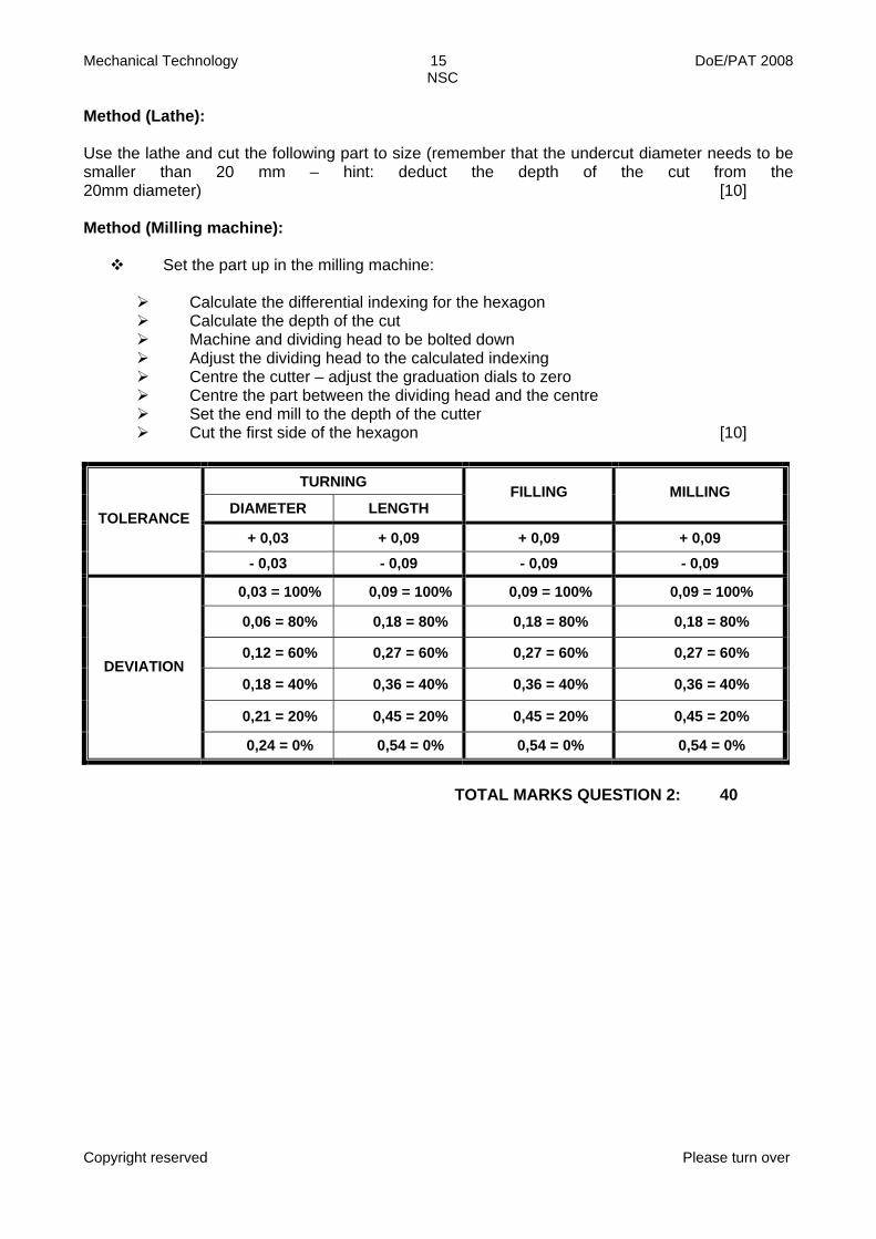
Method (Lathe): Use the lathe and cut the following part to size (remember that the undercut diameter needs to be smaller than 20 mm – hint: deduct the depth of the cut from the 20mm diameter) [10] Method (Milling machine):
Set the part up in the milling machine:
Calculate the differential indexing for the hexagon Calculate the depth of the cut Machine and dividing head to be bolted down Adjust the dividing head to the calculated indexing Centre the cutter – adjust the graduation dials to zero Centre the part between the dividing head and the centre Set the end mill to the depth of the cutter Cut the first side of the hexagon [10]
TURNING
DIAMETER LENGTH FILLING MILLING
+ 0,03 + 0,09 + 0,09 + 0,09 TOLERANCE
- 0,03 - 0,09 - 0,09 - 0,09
0,03 = 100% 0,09 = 100% 0,09 = 100% 0,09 = 100%
0,06 = 80% 0,18 = 80% 0,18 = 80% 0,18 = 80%
0,12 = 60% 0,27 = 60% 0,27 = 60% 0,27 = 60%
0,18 = 40% 0,36 = 40% 0,36 = 40% 0,36 = 40%
0,21 = 20% 0,45 = 20% 0,45 = 20% 0,45 = 20%
DEVIATION
0,24 = 0% 0,54 = 0% 0,54 = 0% 0,54 = 0%
TOTAL MARKS QUESTION 2: 40

Mechanical Technology 16 DoE/PAT 2008 NSC
Copyright reserved Please turn over
QUESTION 3
INTERNAL COMBUSTION ENGINES
1. Assessment
Measurements on the size of the engine Calculations on the volume of the cylinder State possible methods to increase the compression ratio Calculations on the new compression ratio if dimensions is altered
2. Requirements
Inside micrometer Depth micrometer Calculator Engine: cylinder head removed
3. Method
Measure the diameter of the cylinder with an inside micrometer or telescopic gauge Measure the total length of the cylinder from the B.D.C (Bottom dead centre) to the
T.D.C (Top dead centre).
FIGURE 6

Mechanical Technology 17 DoE/PAT 2008 NSC
Copyright reserved Please turn over
ASSESSMENT: Use an internal combustion engine to perform the following measurements and tests: 3.1 Measure the diameter of the cylinder with an inside micrometer. Neatly draw the reading
according to the scale. (2) 3.2 Measure the total length of the cylinder from the Bottom Dead Centre (B.D.C) to the Top
Dead Centre. (1) 3.3 State TWO possible reasons for increasing the compression ratio of an internal combustion
engine. (2) 3.4 State seven methods on how the compression ratio of an internal combustion engine can
be increased. (7) 3.5 Calculate the volume of the cylinder. (2) 3.6 Calculate the size of the engine (i.e. for a four-/or a six-cylinder engine). (1) 3.7 Show by means of calculations how the compression ratio is affected by altering the
diameter of the cylinder. (2) 3.8 Calculate the stroke volume (SV = V1). See figure 6. (2) 3.9 Calculate the clearance volume (CV = V2). See figure 56. (2) 3.10 Calculate the compression ratio (CR). (1) 3.11 Calculate the compression ratio if the diameter of the cylinder is increased
by 1,0 mm. (2) 3.12 Carry out a compression pressure test on the engine using a compression gauge. Clearly
outline the procedure that has been used. (6) [30]
TOTAL MARKS: 100

Mechanical Technology 18 DoE/PAT 2008 NSC
Copyright reserved Please turn over
Calculations: Hint: Use the rubrics as for milling and turning. Each measurement will differ from engine to engine. Measure the diameter of the cylinder with an inside micrometer = D
Measure the total length of the cylinder from the B.D.C (Bottom dead centre) to the
T.D.C (Top dead centre) = L
Calculate the stroke volume = SV (V1)
Calculate the clearance volume = CV (V2)
Calculate the compression ratio = CR

Mechanical Technology 19 DoE/PAT 2008 NSC
Copyright reserved Please turn over
ASSESSMENT GUIDELINES
METHODS OF ASSESSMENT
(Who carries out the assessment?)
Self-assessment Peer assessment Group assessment Educator assessment
ASSESSMENT FORMS
Presentation Debate or argument Interview Demonstration Questionnaire Role-play Test Examination Project Simulation Research or investigation Assignment Case study Practical task
TOOLS FOR ASSESSING LEARNER PERFORMANCE
Rubrics Rating scales, Checklists, Observation sheets, Marking memoranda, Assessment grids, etc.
RECORDING TOOLS
Class list, Mark sheet, Day-by-day assessment sheets, Promotion schedule, etc
REPORTING TOOLS
Report card using national codes and comments on competence, Educator-parent interview, Educator-learner interview, Written comments in learner work books, Day-by-day assessment sheets, etc.

Mechanical Technology 20 DoE/PAT 2008 NSC
Copyright reserved Please turn over
GRADE 12 - PROGRAMME OF ASSESSMENT
INTERNAL
ASSESSMENT TASKS(100 marks)
EXTERNAL ASSESSMENT TASKS (300 marks)
25% 75%
PAT EXAM PAPER
25% (100 marks) 50% (200 marks)
• 2 tests
• 2 exams (June & Trial)
• 2 practical tasks
• Integrate project portfolio with the practical project LO1-4
• Main focus LO4
• Portfolio = 25%
• Project/artefact = 75%
• Written exam LO1-4
• Main focus LO1-3
Assessment Tasks Term One Term Two
Term Three
Term Four Marks
Tests 1 1 5
Examination (mid-year) 1 1 10
Practical tasks (simulations, investigations, small practical tasks)
1 1 10
Total assessment tasks 25
Written Theory Paper
1 50 End-of-year Assessment Practical
Assessment Task
1 25

Mechanical Technology 21 DoE/PAT 2008 NSC
Copyright reserved Please turn over
PUNTESTAAT: GRAAD 12 / MARK SHEET: GRADE 12 VAK: SUBJECT:
ONDERWYSER: EDUCATOR:
GRAAD: GRADE:
SKOOL: SCHOOL:
AREA-PROJEKKANTOOR: AREA PROJECT OFFICE:
AANTAL LEERDERS: NUMBER OF STUDENTS:
SENTRUM NOMMER: CENTRE NUMBER: STREEK:
REGION: JAAR: YEAR:
ASSESSMENT TASKS PRACTICAL
ASSESSMENT TASK FI
NA
L EX
AM
I-N
ATI
ON
FI
NA
L PR
OM
O-
TIO
N
MA
RK
TEST
1ST
TER
M
TEST
3R
D T
ERM
JUN
E EX
AM
TRA
IL E
XAM
MA
NU
FAC
TUR
ING
JO
ININ
G
MA
INTE
NA
NC
E
FIN
AL
MA
RK
PRO
JEC
T PO
RTF
OLI
O
PRO
JEC
T
FIN
AL
PAT
SURNAMES OF STUDENTS (ALPHABETICAL)
INIT
IALS
10 10 20 20 20 20 100 25 75 100 200 400 1. • • 2. • • 3. • 4. • • • 5. • • 6. • 7. 8. • • • 9. 10.
TOTAL EVIDENCE OF ALL MARKS MUST BE IN LEARNERS PORTFOLIO AVERAGE
EDUCATOR: DATE:
HOD: DATE:
PRINCIPAL: DATE:
SUBJECT ADVISOR: DATE:

Mechanical Technology 22 DoE/PAT 2008 NSC
Copyright reserved Please turn over
ANNEXURE A: RUBRIC FOR ASSESSMENT OF DESIGN PORTFOLIO
7 6 5 4 3 2 1 CRITERIA 80 –100% 70 - 79% 60 - 69% 50 - 59% 40 - 49% 30 - 39% 0 - 29%
Presentation
Exceeded the required information, extremely neat: Name Register class Year 20… Appropriate cover illustration Appropriate title Index All sections Page numbers
Required information extremely neat: Name Register class Year 20… Appropriate cover illustration Appropriate title Index All sections Page numbers
Adequate information from list below, neatlypresented:
Necessary information from list below, neatlypresented:
Name Register class, Year 20… Appropriate cover illustration Appropriate title Index All sections Page numbers
Limited information from list below, neatly presented:
Name Register class Year 20…Appropriate cover illustration Appropriate title
Year 20…Appropriate cover illustration
Index All sections Page numbers
Name Register class
Lack of essential information, not very neatly presented
Appropriate title Index All sections Page numbers
Only name and register class untidily presented
Development of a design brief
The design brief is extremely wellformulated anddefines the need or opportunity.
The design brief is very wellconstructed and defines the need or opportunity.
It lists detailed specifications and constraints.
The design brief is well constructed and defines the need oropportunity.
It lists detailed specifications and constraints.
The design brief defines the need or opportunity and provides a list of specifications and constraints.
It lists detailed specifications and constraints.
The design brief defines the needs or opportunity and provides limited specifications.
The simple design brief makes little reference to the need or problem.
The design brief is vague and lists no specifications or constraints.
Investigation and analyses
information
Shows evidence of a variety of strategies *(6) of investigation used to obtain all relevant information to assist in developing innovative design ideas.
Uses a wide range*(5) ofappropriate information sources to developinnovative design options.
Uses of a range of information sources*(4) which shows understanding for the problem or need.
Uses adequate sources *(3) to collect relevantinformation toassist with design ideas.
Uses relevant research *(2) to address theproblem or need identified in the design brief.
Uses less than adequate sources* (1) and collects less than adequateinformation.
Collects very little relevant information *(0).

Mechanical Technology 23 DoE/PAT 2008 NSC
Copyright reserved Please turn over
Generation of design ideas
Generates an excellent variety of alternative andinnovative ideas with differentapproaches toaddress theproblem or need. Justifies thepreferred option with clear links to the design brief.
Shows evidence of a wide range of communication methods used to develop original and creative design options.
Substantiates well choice of final design.
Shows evidence of a range of communication methods used to develop original and creative design options including modelling design ideas. Explains wellreasoned choice of final design.
Well reasonedchoice of final design.
Uses a good variety ofalternatives exploring different approaches.
Considers alternatives butlacks in originality and flair.
Indicates finaldesign choice.
Offers some alternatives but tends to be a collection of existing products with limited reasoning of choice. Shows limited links with research done.
Shows little or no exploration of alternatives.
Communication of ideas
Develops a very interesting solution and communicates it exceptionally well using appropriate techniques and methods. Usesmodelling ideas to test and explore design thinking.
Develops a very interesting solution and communicated it very well using appropriate techniques andmethods.
Develops an interesting solution and effectivelycommunicates it effectively using appropriate techniques.
Reasons well for choice of solution. Uses good overall communication techniques.
The solution lacks creativity with limited communication techniques used.
The solution lacks creativity withinappropriate communication techniques used.
The solution lacks detail, making interpretation difficult. Scant attention is given to communication techniques.
Evaluation of product or
artefact
Comprehensively evaluates theproduct against the design brief taking account of the user and cost-effectiveness. Evaluates procedures, techniques andprocesses andindicates possible improvements. Evaluates theappropriateness of the materials used.
Evaluates the product against the design brief taking account of the user and cost-effectiveness.
Evaluates procedures, techniques and processes andindicates possible improvements. Evaluates theappropriateness of the materials used.
Evaluates theappropriateness of the materials used with limited suggestions for improvement.
Evaluates the product against the design brief. Present suggestions toimprove onfunction.
Evaluates theproduct against the design brief.
Evaluates theappropriateness of the materials used.
Superficially evaluates the product against the design brief.
Makes recommendations to improve its functionality.
Very superficially evaluates withlimited recommendations.
Shows little or no evidence of an evaluation of the project.

Mechanical Technology 24 DoE/PAT 2008 NSC
Copyright reserved Please turn over
ANNEXURE B: RUBRIC FOR ASSESSMENT OF FINAL PRODUCT/ARTEFACT
7 6 5 4 3 2 1CRITERIA 80 -100% 70 - 79% 60 - 69% 50 - 59% 40 - 49% 30 - 39% 0 - 29%
FITNESS FOR PURPOSE
This product has an outstanding level of functionality. It shows a very high level of innovation that is appropriate to the design brief.
The product demonstrates a high level of functionality. It shows a high level of innovation that is appropriate to the design brief.
The product fulfils adequately the purpose for which it was designed. It shows some innovation that is appropriate to the design brief.
The product fulfils satisfactorily the purpose for which it was designed. It shows limited innovation for the identified need/problem.
The product fulfils its functional requirements. No evidence of innovation in the solution to the identified need/problem.
The product barely fulfils functional requirements but lacks any refinement/innovation.
The project is incomplete and does not fulfil the identified need/problem.
MANUFACTURING COMPETENCY
Demonstration of an outstanding level of skill/competence in the correct and safe use of a wide range of materials, tools, equipment and machines under educator supervision.
Demonstrates a very high level of skill/competence in the correct and safe use of a wide range of materials, tools, equipment and machines under educator supervision.
Demonstrates a high level of skill/competence in the correct and safe use of a range of materials, tools, equipment and machines under educator supervision.
Demonstrates a satisfactory level of skill/competence in the correct and safe use of appropriate materials, tools, equipment and machines under educator supervision.
Demonstrates an acceptable level of skill/competence in the correct and safe use of appropriate materials, tools, equipment and machines under educator supervision.
Demonstrates some regard for accuracy and safety in the use of materials, tools, equipment and machines under educator supervision.
Demonstrates a lack of skill/competence in the use of appropriate materials, tools, equipment and machines under educator supervision. Pays little attention to safety.
PLANNING
Demonstrates continual review of the making process. Shows outstanding ability to adapt and modify the design when difficulties arise. Adopts procedures to minimise waste, manages time outstandingly well.
Reviews design during the making process, demonstrates resourcefulness and adaptability in making modifications to ensure a high quality product. Excellent waste and time management.
Shows ability to adapt and modify the design when difficulties arise. Adequate planning to minimise waste, manages time well.
Apply knowledge of materials and processes to overcome problems in making when these arise. Demonstrates a good sense of material and time management.
Shows evidence of adopting alternative ways of proceeding when difficulty is experienced. Seeks assistance from educator to proceed. . Demonstrates some sense of material and time management.
Shows little evidence of alternative ways of proceeding when difficulty is experienced. Does not seek assistance from educator and to proceeds regardless of time and material management.
No attempt made to overcome making problems. No proper planning evident resulting in any regard for time and material management.

Mechanical Technology 25 DoE/PAT 2008 NSC
Copyright reserved Please turn over
An outstanding degree of skill in the surface finishing is demonstrated. The surface finish is of an exceptional quality.
A very high degree of skill in the surface finishing is demonstrated. The surface finish is blemish free.
A high degree of skill in the surface finishing is demonstrated.
A satisfactory level of skill in the surface finish is demonstrated but with some blemishes evident.
A low level of skill in the surface finishing is demonstrated. Blemishes are evident.
A very low level of skill in the surface finishing is demonstrated.
No surface finish evident. SURFACE FINISH
( where applicable in construction)
OR
MODELLING THE PRODUCT
( where product is not a construction)
Exceptionally modelled to illustrate, realistically, its function for which it was developed
Specialist modelling techniques used to demonstrate, realistically, the function for which it was developed.
Product is effectively modelled to illustrate the function for which it was developed.
Product is adequately modelled to illustrate the function for which it was developed.
Product is modelled to illustrate the function for which it was developed.
Product barely illustrates the function for which it was developed.
No clarity as to how the product is to function.

Mechanical Technology 26 DoE/PAT 2008 NSC
Copyright reserved Please turn over
DEPARTMENT OF EDUCATION
DEPARTEMENT VAN ONDERWYS
MECHANICAL TECHNOLOGY
MEGANIESE
TEGNOLOGIE PUNTESTAAT VIR PRAKTIESE ASSESSERINGSTAAK MARK SHEET FOR PRACTICAL ASSESSMENT TASK
GRAAD: JAAR/YEAR: SKOOL/SCHOOL:
DATUM BEGIN/DATE STARTED: DATUM VOLTOOI/DATE COMPLETED:
VAK/SUBJECT: MECHANICAL TECHNOLOGY ONDERWYSER/EDUCATOR:
PROJEK/PROJECT: MANUFACTURING/JOINING METHODS
GETAL LEERLINGE/NUMBER OF LEARNERS:
NAME VAN LEERDERS/NAMES OF LEARNERS
FASETTE/FACETS
INVESTIGATIVE TASK
PU
NTE
/ M
AR
KS
1 2 3 4 5 6 7 8 9 10
11
12
13
14
15
Preparation of mild steel plates 10 Alignment 5 Brazing 10 Break test 5 Visual inspection 10 Discussion 5
FINISHING 5 TYD/TIME
TOTAAL/TOTAL 50 ÷ 50 X 8 8
HANDTEKENING VAN ONDERWYSER/SIGNATURE OF EDUCATOR:
HANDTEKENING VAN DEPT. HOOF/SIGNATURE OF HEAD OF DEPARTMENT:
HANDTEKENING VAN HOOF/SIGNATURE OF PRINCIPAL:
HANDTEKENING VAN VAKADVISEUR/SIGNATURE OF SUBJECT ADVISOR:

Mechanical Technology 27 DoE/PAT 2008 NSC
Copyright reserved Please turn over
DEPARTMENT OF EDUCATION
DEPARTEMENT VAN ONDERWYS
MECHANICAL TECHNOLOGY
MEGANIESE
TEGNOLOGIE PUNTESTAAT VIR PRAKTIESE ASSESSERINGSTAAK MARK SHEET FOR PRACTICAL ASSESSMENT TASK
GRAAD: JAAR/YEAR: SKOOL/SCHOOL:
DATUM BEGIN/DATE STARTED: DATUM VOLTOOI/DATE COMPLETED:
VAK/SUBJECT: MECHANICAL TECHNOLOGY ONDERWYSER/EDUCATOR:
PROJEK/PROJECT: MANUFACTURING/JOINING METHODS
GETAL LEERLINGE/NUMBER OF LEARNERS:
NAME VAN LEERDERS/NAMES OF LEARNERS
FASETTE/FACETS
MOTOR TRESTLE
PU
NTE
/ M
AR
KS
1 2 3 4 5 6 7 8 9 10
11
12
13
14
15
Drilling 5 Pitch of hole 10
Square ness of braces 10 Tack welding 5 Arc welding 20 Gas welding 10
Assembly 10 Safety 5
FINISHING 10 TYD/TIME 5
TOTAAL/TOTAL 90 ÷ 90 X 22 22
HANDTEKENING VAN ONDERWYSER/SIGNATURE OF EDUCATOR:
HANDTEKENING VAN DEPT. HOOF/SIGNATURE OF HEAD OF DEPARTMENT:
HANDTEKENING VAN HOOF/SIGNATURE OF PRINCIPAL:
HANDTEKENING VAN VAKADVISEUR/SIGNATURE OF SUBJECT ADVISOR:

Mechanical Technology 28 DoE/PAT 2008 NSC
Copyright reserved Please turn over
QUESTION 2: MILLING
MEMORANDUM
1. Milling machines Figure 1 – Vertical milling machine Figure 2 – Horizontal milling machine (2) 2. Movements
X – horizontal – left and right Y – in and out Z – up and down (3)
3. Type of procedures Figure 3 – Centring of cutter Figure 4 – Straddle milling (2) 4. Differential indexing Simple indexing = 40 / 6 = 6 4/6 = 6 (2/3 x 8/8) = 6 16/24 = 6 full turns and 16 holes on a 24 hole circle (5) 5. Depth of the cut
“x” = BE – BD
uit ∆ BDC volg dat / from ∆ BDC

Mechanical Technology 29 DoE/PAT 2008 NSC
Copyright reserved Please turn over
cos 30° = BD/BC
BD = BC x cos 30°
= 10 x 0.866
= 8.66 mm
dus is / thus:
“x” = 10 – 8.66
DE = 1.34 mm (8)
[20]
**************************************

Mechanical Technology 30 DoE/PAT 2008 NSC
Copyright reserved Please turn over
DEPARTMENT OF EDUCATION
DEPARTEMENT VAN ONDERWYS
MECHANICAL TECHNOLOGY
MEGANIESE
TEGNOLOGIE PUNTESTAAT VIR PRAKTIESE ASSESSERINGSTAAK MARK SHEET FOR PRACTICAL ASSESSMENT TASK
GRAAD: JAAR/YEAR: SKOOL/SCHOOL:
DATUM BEGIN/DATE STARTED: DATUM VOLTOOI/DATE COMPLETED:
VAK/SUBJECT: MECHANICAL TECHNOLOGY ONDERWYSER/EDUCATOR:
PROJEK/PROJECT: MANUFACTURING GETAL LEERLINGE/NUMBER OF LEARNERS:
NAME VAN LEERDERS/NAMES OF LEARNERS
FASETTE/FACETS
TURNING
PU
NTE
/ M
AR
KS
1 2 3 4 5 6 7 8 9 10
11
12
13
14
15
Diameter A 10 Diameter B 10 Diameter C 10 Diameter D 10 Total Length 10
FNISHING 10 TYD/TIME
TOTAAL/TOTAL 60 ÷ 60 X 10 10
HANDTEKENING VAN ONDERWYSER/SIGNATURE OF EDUCATOR:
HANDTEKENING VAN DEPT. HOOF/SIGNATURE OF HEAD OF DEPARTMENT:
HANDTEKENING VAN HOOF/SIGNATURE OF PRINCIPAL:
HANDTEKENING VAN VAKADVISEUR/SIGNATURE OF SUBJECT ADVISOR:

Mechanical Technology 31 DoE/PAT 2008 NSC
Copyright reserved Please turn over
DEPARTMENT OF EDUCATION
DEPARTEMENT VAN ONDERWYS
MECHANICAL TECHNOLOGY
MEGANIESE
TEGNOLOGIE PUNTESTAAT VIR PRAKTIESE ASSESSERINGSTAAK MARK SHEET FOR PRACTICAL ASSESSMENT TASK
GRAAD: JAAR/YEAR: SKOOL/SCHOOL:
DATUM BEGIN/DATE STARTED: DATUM VOLTOOI/DATE COMPLETED:
VAK/SUBJECT: MECHANICAL TECHNOLOGY ONDERWYSER/EDUCATOR:
PROJEK/PROJECT: MANUFACTURING GETAL LEERLINGE/NUMBER OF LEARNERS:
NAME VAN LEERDERS/NAMES OF LEARNERS
FASETTE/FACETS
MILLING
PU
NTE
/ M
AR
KS
1 2 3 4 5 6 7 8 9 10
11
12
13
14
15
Bolt down of dividing head 5 Assembly of cutter 5 Clamping of shaft 5 Centring of cutter 10 Setting up the index plate indexing 10 Setting of depth 5 Use of dividing head / sector arms 10 Accuracy of hexagon – use rubric 10
FINISHING 5 TYD/TIME 5
TOTAAL/TOTAL 70 ÷ 70 X 10 10
HANDTEKENING VAN ONDERWYSER/SIGNATURE OF EDUCATOR:
HANDTEKENING VAN DEPT. HOOF/SIGNATURE OF HEAD OF DEPARTMENT:
HANDTEKENING VAN HOOF/SIGNATURE OF PRINCIPAL:
HANDTEKENING VAN VAKADVISEUR/SIGNATURE OF SUBJECT ADVISOR:

Mechanical Technology 32 DoE/PAT 2008 NSC
Copyright reserved Please turn over
DEPARTMENT OF EDUCATION
DEPARTEMENT VAN ONDERWYS
MECHANICAL TECHNOLOGY
MEGANIESE
TEGNOLOGIE PUNTESTAAT VIR PRAKTIESE ASSESSERINGSTAAK MARK SHEET FOR PRACTICAL ASSESSMENT TASK
GRAAD: JAAR/YEAR: SKOOL/SCHOOL:
DATUM BEGIN/DATE STARTED: DATUM VOLTOOI/DATE COMPLETED:
VAK/SUBJECT: MECHANICAL TECHNOLOGY ONDERWYSER/EDUCATOR:
PROJEK/PROJECT: MANUFACTURING GETAL LEERLINGE/NUMBER OF LEARNERS:
NAME VAN LEERDERS/NAMES OF LEARNERS
FASETTE/FACETS
MILLING – FINAL MARKS
PU
NTE
/ M
AR
KS
1 2 3 4 5 6 7 8 9 10
11
12
13
14
15
Calculations 20 Lathe 10 Milling 10
FINISHING TYD/TIME
TOTAAL/TOTAL 40 HANDTEKENING VAN ONDERWYSER/SIGNATURE OF EDUCATOR:
HANDTEKENING VAN DEPT. HOOF/SIGNATURE OF HEAD OF DEPARTMENT:
HANDTEKENING VAN HOOF/SIGNATURE OF PRINCIPAL:
HANDTEKENING VAN VAKADVISEUR/SIGNATURE OF SUBJECT ADVISOR:

Mechanical Technology 33 DoE/PAT 2008 NSC
Copyright reserved
DEPARTMENT OF EDUCATION
DEPARTEMENT VAN ONDERWYS
MECHANICAL TECHNOLOGY
MEGANIESE
TEGNOLOGIE PUNTESTAAT VIR PRAKTIESE ASSESSERINGSTAAK MARK SHEET FOR PRACTICAL ASSESSMENT TASK
GRAAD: JAAR/YEAR: SKOOL/SCHOOL:
DATUM BEGIN/DATE STARTED: DATUM VOLTOOI/DATE COMPLETED:
VAK/SUBJECT: MECHANICAL TECHNOLOGY ONDERWYSER/EDUCATOR:
PROJEK/PROJECT: PRACTICAL ASSESSMENT TASK
GETAL LEERLINGE/NUMBER OF LEARNERS:
NAME VAN LEERDERS/NAMES OF LEARNERS
FASETTE/FACETS
FINAL MARKS
PU
NTE
/ M
AR
KS
1 2 3 4 5 6 7 8 9 10
11
12
13
14
15
QUESTION 1: JOINING Investigative task 8 Motor trestle 22 QUESTION 2: MILLING 40 QUESTION 3: ENGINE 30
FINISHING 0 TYD/TIME 0
TOTAAL/TOTAL 100 % 100
HANDTEKENING VAN ONDERWYSER/SIGNATURE OF EDUCATOR:
HANDTEKENING VAN DEPT. HOOF/SIGNATURE OF HEAD OF DEPARTMENT:
HANDTEKENING VAN HOOF/SIGNATURE OF PRINCIPAL:
HANDTEKENING VAN VAKADVISEUR/SIGNATURE OF SUBJECT ADVISOR: