mechanical theory/technology - centec: … … · · 2009-10-06there are three types of...
TRANSCRIPT

MECHANICAL THEORY/TECHNOLOGY
Turn on bookmarks to navigate this document
Copyright © 2002 CenTec, Inc.
All rights reserved. No part of this material may be reproduced or distributed in an form or by any means, or stored in any data base or retrieval system, without the prior written permission from:
CenTec, Inc. P.O. Box 5127, Greenville, S.C, 29606

BEARINGS
Copyright © 2002 CenTec, Inc.
All rights reserved. No part of this material may be reproduced or distributed in an form or by any means, or stored in any data base or retrieval system, without the prior written permission from:
CenTec, Inc. P.O. Box 5127, Greenville, S.C, 29606

BEARINGS AND THEIR CATEGORIES Generalities A bearing is a mechanical device and it is important to know its various components.
1 2 Figure 1-1 KEY 1) Inner race. 7) Side of inner race. 2) Inner race chamfer. 8) Side of outer race. 3) Inner race track. 9) Cylindrical roller. 4) Outer race track. 10) Cylindrical roller track 5) Outer race. 11) Outer race. 6) Ball. 12) Cage
Copyright © 2002 CenTec, Inc.
All rights reserved. No part of this material may be reproduced or distributed in an form or by any means, or stored in any data base or retrieval system, without the prior written permission from:
CenTec, Inc. P.O. Box 5127, Greenville, S.C, 29606

Categories of bearings When in operation, a shaft is subjected to axial and radial forces which tend to push it away from its axis centre. Bearings are positioned to resist to these forces and maintain the shaft in proper equilibrium.
Figure 1-2
Manufacturers have grouped bearings under two headings, on the basis of the forces being encountered: radial bearings and axial bearings.
Copyright © 2002 CenTec, Inc.
All rights reserved. No part of this material may be reproduced or distributed in an form or by any means, or stored in any data base or retrieval system, without the prior written permission from:
CenTec, Inc. P.O. Box 5127, Greenville, S.C, 29606

Radial bearings Radial bearings are made with balls or rollers, depending on the how the bearings are used. They are designed to withstand forces that are perpendicular to the axis of the shaft.
Figure 1-3 Axial bearings Axial bearings, also known as thrust bearings, have either balls or rollers, but both are designed to withstand axial forces, which push or pull along the axis.
Figure 1-4
Copyright © 2002 CenTec, Inc.
All rights reserved. No part of this material may be reproduced or distributed in an form or by any means, or stored in any data base or retrieval system, without the prior written permission from:
CenTec, Inc. P.O. Box 5127, Greenville, S.C, 29606

Radial bearings and their functions Ball bearings
Name Function
Rigid, with balls and deep track.
Designed mainly to support radial loads, but can also take a bit of axial load.
Figure 2-1
Name FunctionWith filling notch. (Maxi-ball)
Designed to take a higher radial load than the bearing with deep tracks. However, the filling notch prevents the support of axial loads.
Figure 2-2
Name FunctionWith deep tracks equipped with a shield.
The shield protects the interior of the bearing from dirt.
Figure 2-3
Name Function
With two rows of balls. These bearings have the same feature as the single-row bearings, but they can take heavy radial loads.
Figure 2-4
Copyright © 2002 CenTec, Inc.
All rights reserved. No part of this material may be reproduced or distributed in an form or by any means, or stored in any data base or retrieval system, without the prior written permission from:
CenTec, Inc. P.O. Box 5127, Greenville, S.C, 29606
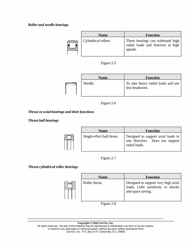
Roller and needle bearings
Name FunctionCylindrical rollers. These bearings can withstand high
radial loads and function at high speeds.
Figure 2-5
Name Function
Needle. To take heavy radial loads and use less headroom.
Figure 2-6 Thrust or axial bearings and their functions Thrust ball bearings
Name Function
Single-effect ball thrust. Designed to support axial loads in one direction. Does not support radial loads.
Figure 2-7 Thrust cylindrical roller bearings
Name Function
Roller thrust. Designed to support very high axial loads. Little sensitivity to shocks and space saving.
Figure 2-8
Copyright © 2002 CenTec, Inc.
All rights reserved. No part of this material may be reproduced or distributed in an form or by any means, or stored in any data base or retrieval system, without the prior written permission from:
CenTec, Inc. P.O. Box 5127, Greenville, S.C, 29606
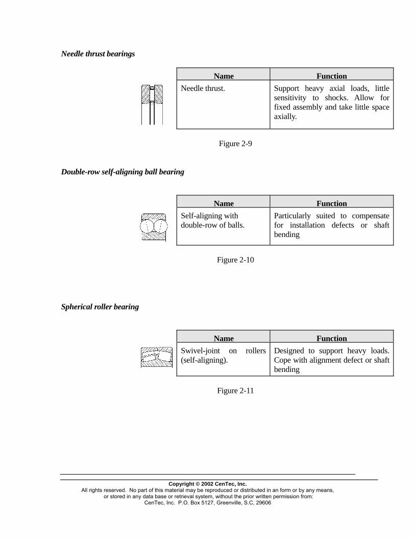
Needle thrust bearings
Name Function
Needle thrust. Support heavy axial loads, little sensitivity to shocks. Allow for fixed assembly and take little space axially.
Figure 2-9 Double-row self-aligning ball bearing
Name Function
Self-aligning with double-row of balls.
Particularly suited to compensate for installation defects or shaft bending
Figure 2-10 Spherical roller bearing
Name FunctionSwivel-joint on rollers (self-aligning).
Designed to support heavy loads. Cope with alignment defect or shaft bending
Figure 2-11
Copyright © 2002 CenTec, Inc.
All rights reserved. No part of this material may be reproduced or distributed in an form or by any means, or stored in any data base or retrieval system, without the prior written permission from:
CenTec, Inc. P.O. Box 5127, Greenville, S.C, 29606
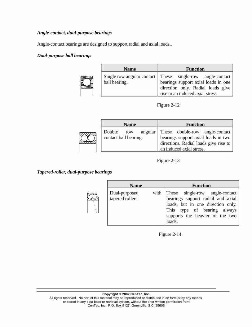
Angle-contact, dual-purpose bearings Angle-contact bearings are designed to support radial and axial loads.. Dual-purpose ball bearings
Name FunctionSingle row angular contact ball bearing.
These single-row angle-contact bearings support axial loads in one direction only. Radial loads give rise to an induced axial stress.
Figure 2-12
Name FunctionDouble row angular contact ball bearing.
These double-row angle-contact bearings support axial loads in two directions. Radial loads give rise to an induced axial stress.
Figure 2-13 Tapered-roller, dual-purpose bearings
Name Function
Dual-purposed with tapered rollers.
These single-row angle-contact bearings support radial and axial loads, but in one direction only. This type of bearing always supports the heavier of the two loads.
Figure 2-14
Copyright © 2002 CenTec, Inc.
All rights reserved. No part of this material may be reproduced or distributed in an form or by any means, or stored in any data base or retrieval system, without the prior written permission from:
CenTec, Inc. P.O. Box 5127, Greenville, S.C, 29606

Bearing Identification Codes
Figure 3-4
In the precision and play (clearance) suffixes, "P" refers to the tolerances of each bearing component and "C" refers to the precision of radial play between the rolling element and the race (track).
Copyright © 2002 CenTec, Inc.
All rights reserved. No part of this material may be reproduced or distributed in an form or by any means, or stored in any data base or retrieval system, without the prior written permission from:
CenTec, Inc. P.O. Box 5127, Greenville, S.C, 29606

Internal Clearance The internal clearance has a direct impact on the tightness of the bearing around the shaft. Therefore, one must replace a bearing by another of the same type with the same dimensions and clearance.
This chart is an example of differences between the various clearance codes. It explains the precision variance pertaining to the radial clearance for an identical bearing, but with a different degree of precision. The normal clearance is the standard manufacturing clearance. Conversion of values into the imperial system To convert into inches the values shown in microns (SI), simply divided the microns by
25.4. 1 thousandth of an inch = 25.4 microns 1 micron - 0.001 mm In order to do so, apply the rule of three. Example: 1 mm of an inch = 25.4 microns x = 2 microns 1 x 2 = 0.0787 thousandth of an inch 25.4 = 0.0000787 inch
Copyright © 2002 CenTec, Inc.
All rights reserved. No part of this material may be reproduced or distributed in an form or by any means, or stored in any data base or retrieval system, without the prior written permission from:
CenTec, Inc. P.O. Box 5127, Greenville, S.C, 29606
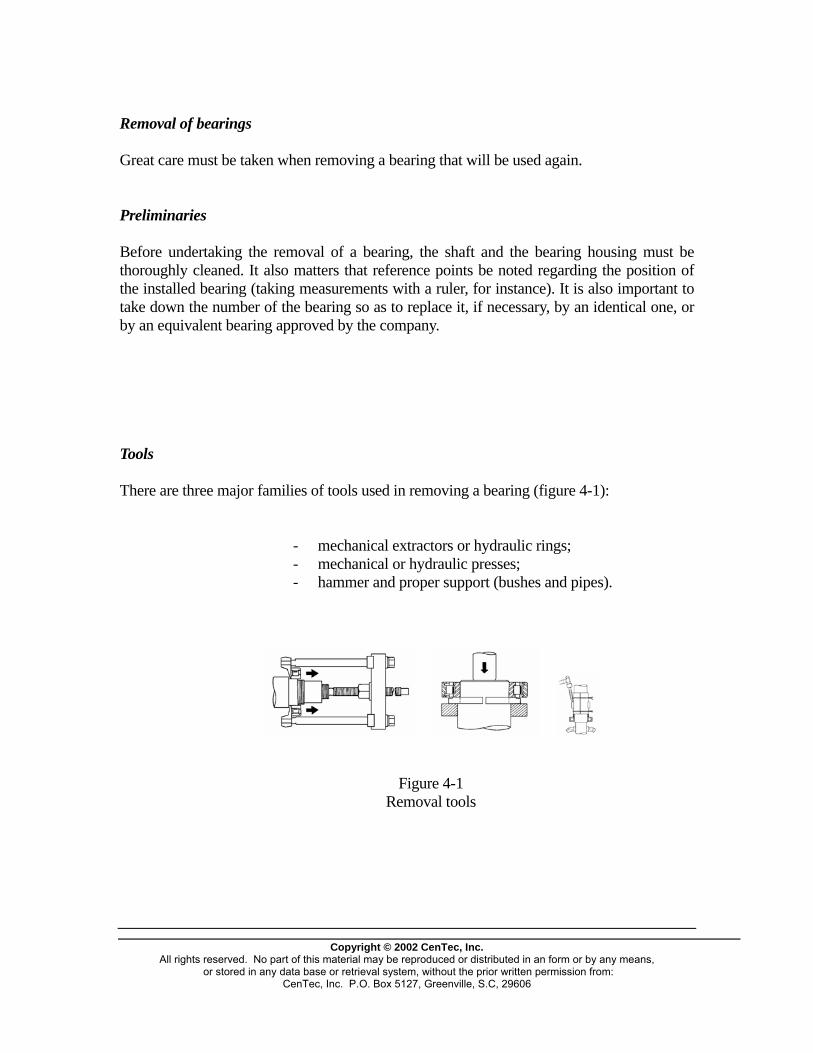
Removal of bearings Great care must be taken when removing a bearing that will be used again. Preliminaries Before undertaking the removal of a bearing, the shaft and the bearing housing must be thoroughly cleaned. It also matters that reference points be noted regarding the position of the installed bearing (taking measurements with a ruler, for instance). It is also important to take down the number of the bearing so as to replace it, if necessary, by an identical one, or by an equivalent bearing approved by the company. Tools There are three major families of tools used in removing a bearing (figure 4-1): - mechanical extractors or hydraulic rings; - mechanical or hydraulic presses; - hammer and proper support (bushes and pipes).
Figure 4-1 Removal tools
Copyright © 2002 CenTec, Inc.
All rights reserved. No part of this material may be reproduced or distributed in an form or by any means, or stored in any data base or retrieval system, without the prior written permission from:
CenTec, Inc. P.O. Box 5127, Greenville, S.C, 29606
Copyright © 2002 CenTec, Inc.
All rights reserved. No part of this material may be reproduced or distributed in an form or by any means, or stored in any data base or retrieval system, without the prior written permission from:
CenTec, Inc. P.O. Box 5127, Greenville, S.C, 29606
BEARING LUBRICATION METHODS Introduction to lubrication The foremost purpose of lubrication is to create an intermediate coat between the parts sliding or rolling against one another, so that the friction and wear will be minimized as much as possible. There are three types of lubricants: - solid (powder); - liquid (oil); - semi-solid (grease). Each has its own advantages and specific use. Choice of lubricants A properly lubricated bearing will not wear down because the lubricant will prevent the metal parts from touching thanks to a film of oil between the various moving components. When the manufacturer specifies a particular lubricant and a frequency of greasing, those instructions must be respected. Should the manufacturer not have specified anything, the following recommendations will prove useful. In principle, all bearings can be lubricated either with grease or with oil. Ball thrust roller bearings are usually lubricated with oil, grease only being suitable for very low speeds. Bearings protected by flanges or joints have lifetime lubrication, that is they are filled with grease during manufacturing and then sealed. The choice of lubricant is determined mainly by the operating temperature and the speed of rotation. Under normal operation, grease can generally be used. It sticks better to the assembly than oil and it also protects the bearing against humidity and impurities. Lubrication with oil is generally recommended where speed and temperature are high, when heat must be drawn away or when adjoining parts of the machine are lubricated with oil. The speed limits applicable to grease and oil are shown in the bearing charts. Lubricants must be stored in clean and leak-proof containers and placed in a dry area. Grease types
Copyright © 2002 CenTec, Inc.
All rights reserved. No part of this material may be reproduced or distributed in an form or by any means, or stored in any data base or retrieval system, without the prior written permission from:
CenTec, Inc. P.O. Box 5127, Greenville, S.C, 29606
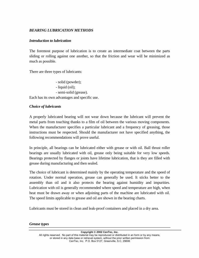
Lubricating greases are oils that contain a thickening agent, usually a metallic soap. When choosing a grease, one must take into account its consistence, the range of operating temperatures and its rust-proofing properties. Consistency is defined in accordance with the NLGI scale (National Lubricating Grease Institute). Basically, metallic-soap greases with a 1, 2 or 3 consistency rating can be used in bearings. The top temperature for calcium greases is about 60�C. If lead soap is added, these greases are particularly suited for "humid" bearings assemblies, for instance in the wet section of papermaking machines. Some calcium-lead greases protect against salt water. Soda greases can be used between -30�C and +80�C and protect against corrosion by producing an emulsion when in contact with humidity. However, they can only absorb a small quantity of water, otherwise they lose their lubricating properties and may leak from the bearing assembly. Lithium greases have an operating range between -30�C and +110�C, and are water resistant. Therefore, they must contain a corrosion inhibitor if the bearing operates in humid surroundings. When lead is added to lithium grease, the lubrication is quite good, even in the presence of water. There are also a number of greases designed to operate at temperatures above 12�C.

Copyright © 2002 CenTec, Inc.
All rights reserved. No part of this material may be reproduced or distributed in an form or by any means, or stored in any data base or retrieval system, without the prior written permission from:
CenTec, Inc. P.O. Box 5127, Greenville, S.C, 29606
Lubrication intervals When no specific instructions have been given, the diagram shown in figure 6-1 will prove a good guide. It is based on the use of a normal-quality grease that resists to aging, and it gives the lubricating intervals in terms of hours of use. The diagram is valid for stationary machines, normal bearing loads and operating temperatures of up to 70�C taken on the outer ring. For each increment of 15�C above 70�C, the lubricating interval given in the chart must be halved, keeping in mind that the upper temperature limit must be respected. In cases where the grease may be contaminated in short order, the assemblies must be protected against water or receive lubricating toppings more frequently than called for by the chart. Quantity of grease When there are no specific instructions, the quantity of grease to be used can be determined by the following equation: G = 0.005 D x B G = grease, in grams. D = diameter of the bearing, in mm. B = width of the bearing, in mm. A number of manufacturers use an equivalent formula that gives the
quantity in ounces: Oz = 0.114 x D x B Oz = grease, in ounces. D = diameter of the bearing, in mm. B = width of the bearing, in mm.
igure 6-1
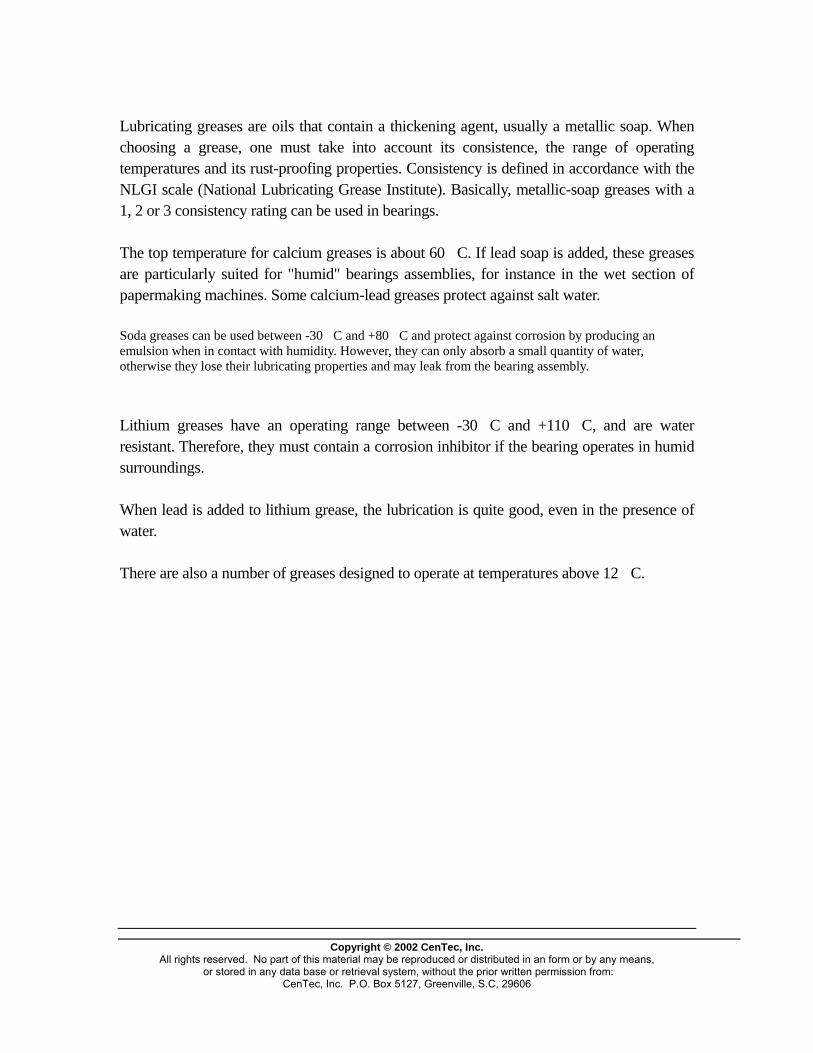
Greasing methods The space between the balls or the rollers needs to be filled with a grease that is appropriate to the operating conditions. The space available around the bearing must normally be filled to 1/3 of its volume. However, when the speeds are high, there should be slightly less grease. If the speed is very low, the space should be completely filled.
Figure 6-2 Filling with grease
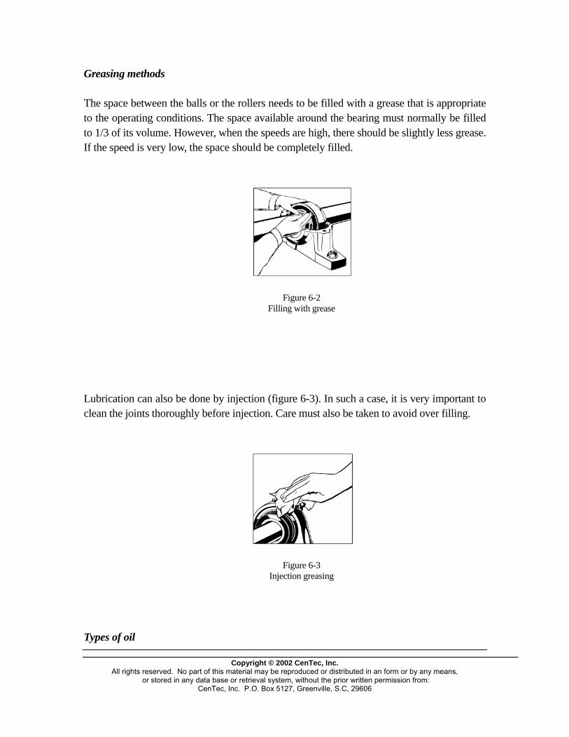
Lubrication can also be done by injection (figure 6-3). In such a case, it is very important to clean the joints thoroughly before injection. Care must also be taken to avoid over filling.
Figure 6-3 Injection greasing
Types of oil
Copyright © 2002 CenTec, Inc.
All rights reserved. No part of this material may be reproduced or distributed in an form or by any means, or stored in any data base or retrieval system, without the prior written permission from:
CenTec, Inc. P.O. Box 5127, Greenville, S.C, 29606
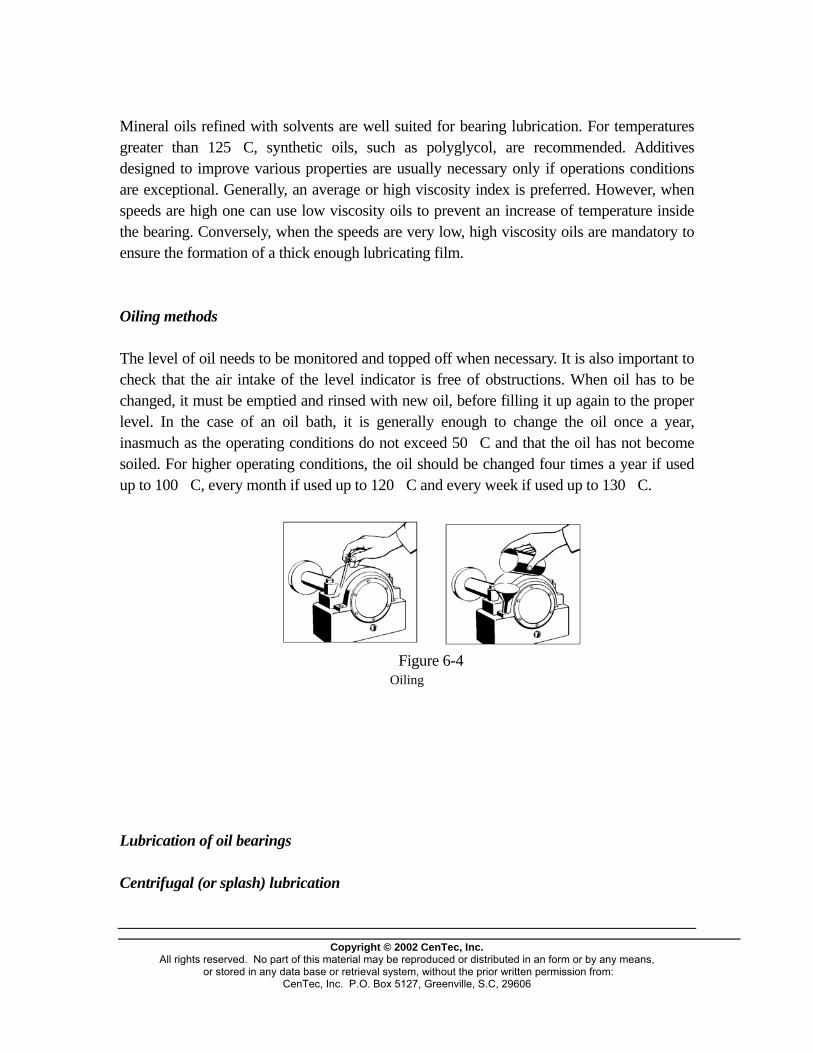
Mineral oils refined with solvents are well suited for bearing lubrication. For temperatures greater than 125�C, synthetic oils, such as polyglycol, are recommended. Additives designed to improve various properties are usually necessary only if operations conditions are exceptional. Generally, an average or high viscosity index is preferred. However, when speeds are high one can use low viscosity oils to prevent an increase of temperature inside the bearing. Conversely, when the speeds are very low, high viscosity oils are mandatory to ensure the formation of a thick enough lubricating film. Oiling methods The level of oil needs to be monitored and topped off when necessary. It is also important to check that the air intake of the level indicator is free of obstructions. When oil has to be changed, it must be emptied and rinsed with new oil, before filling it up again to the proper level. In the case of an oil bath, it is generally enough to change the oil once a year, inasmuch as the operating conditions do not exceed 50�C and that the oil has not become soiled. For higher operating conditions, the oil should be changed four times a year if used up to 100�C, every month if used up to 120�C and every week if used up to 130�C.
Figure 6-4
Oiling Lubrication of oil bearings Centrifugal (or splash) lubrication
Copyright © 2002 CenTec, Inc.
All rights reserved. No part of this material may be reproduced or distributed in an form or by any means, or stored in any data base or retrieval system, without the prior written permission from:
CenTec, Inc. P.O. Box 5127, Greenville, S.C, 29606

Figure 6-5
This is the simplest method of oil lubrication, suited for low rotation speeds. When the bearing is at rest, the level of oil must be just under the centre of the lowest rolling component. Under rotation, the oil is carried about by the motion of the bearing components, goes through the bearing and returns to the pool of oil. For equipment such as the bearings of centrifugal pumps, a glass gauge is often used as level indicator (figure 6-6).
Copyright © 2002 CenTec, Inc.
All rights reserved. No part of this material may be reproduced or distributed in an form or by any means, or stored in any data base or retrieval system, without the prior written permission from:
CenTec, Inc. P.O. Box 5127, Greenville, S.C, 29606

Figure 6-6
Lubrication by oil circulation
Figure 6-7
The higher the operating temperature, the faster the oil loses its properties. To avoid having to replace oil too frequently, the circulation of oil is facilitated by a pump. After it has gone through the bearing, the oil is cleaned and returned to the circuit. This system can also incorporate a cooling cycle to help keep the bearing temperature down.
Copyright © 2002 CenTec, Inc.
All rights reserved. No part of this material may be reproduced or distributed in an form or by any means, or stored in any data base or retrieval system, without the prior written permission from:
CenTec, Inc. P.O. Box 5127, Greenville, S.C, 29606
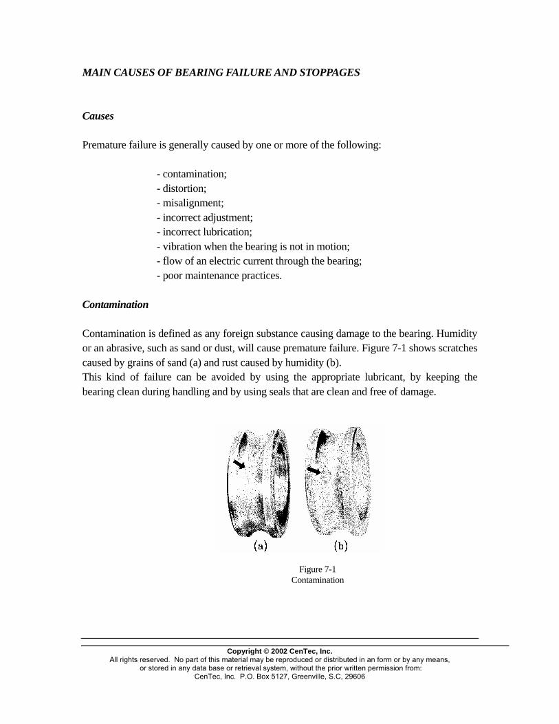
MAIN CAUSES OF BEARING FAILURE AND STOPPAGES Causes Premature failure is generally caused by one or more of the following: - contamination; - distortion; - misalignment; - incorrect adjustment; - incorrect lubrication; - vibration when the bearing is not in motion; - flow of an electric current through the bearing; - poor maintenance practices. Contamination Contamination is defined as any foreign substance causing damage to the bearing. Humidity or an abrasive, such as sand or dust, will cause premature failure. Figure 7-1 shows scratches caused by grains of sand (a) and rust caused by humidity (b). This kind of failure can be avoided by using the appropriate lubricant, by keeping the bearing clean during handling and by using seals that are clean and free of damage.
Figure 7-1 Contamination
Copyright © 2002 CenTec, Inc.
All rights reserved. No part of this material may be reproduced or distributed in an form or by any means, or stored in any data base or retrieval system, without the prior written permission from:
CenTec, Inc. P.O. Box 5127, Greenville, S.C, 29606
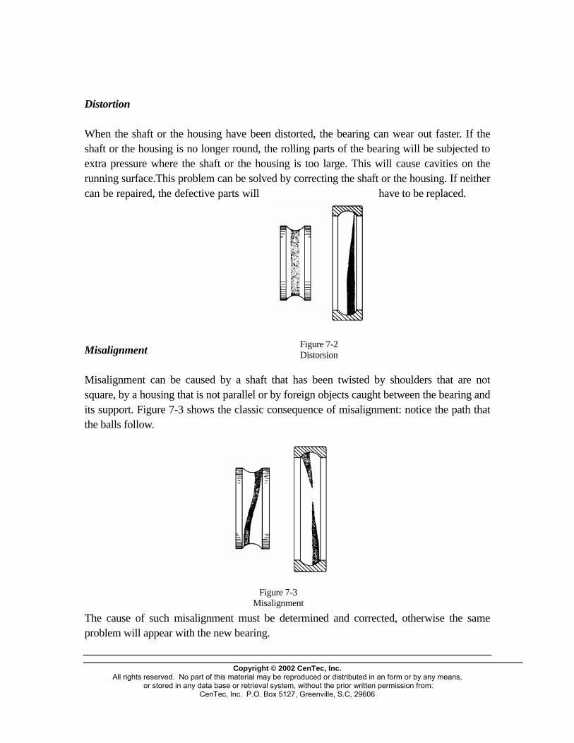
Distortion When the shaft or the housing have been distorted, the bearing can wear out faster. If the shaft or the housing is no longer round, the rolling parts of the bearing will be subjected to extra pressure where the shaft or the housing is too large. This will cause cavities on the running surface.This problem can be solved by correcting the shaft or the housing. If neither can be repaired, the defective parts will have to be replaced.
Figure 7-2 Distorsion
Misalignment Misalignment can be caused by a shaft that has been twisted by shoulders that are not square, by a housing that is not parallel or by foreign objects caught between the bearing and its support. Figure 7-3 shows the classic consequence of misalignment: notice the path that the balls follow.
Copyright © 2002 CenTec, Inc.
All rights reserved. No part of this material may be reproduced or distributed in an form or by any means, or stored in any data base or retrieval system, without the prior written permission from:
CenTec, Inc. P.O. Box 5127, Greenville, S.C, 29606
Figure 7-3 Misalignment
The cause of such misalignment must be determined and corrected, otherwise the same problem will appear with the new bearing.
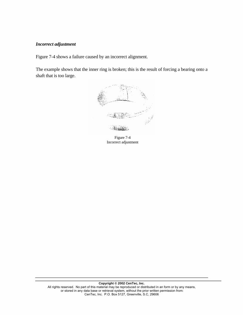
Incorrect adjustment Figure 7-4 shows a failure caused by an incorrect alignment. The example shows that the inner ring is broken; this is the result of forcing a bearing onto a shaft that is too large.
Figure 7-4 Incorrect adjustment
Copyright © 2002 CenTec, Inc.
All rights reserved. No part of this material may be reproduced or distributed in an form or by any means, or stored in any data base or retrieval system, without the prior written permission from:
CenTec, Inc. P.O. Box 5127, Greenville, S.C, 29606
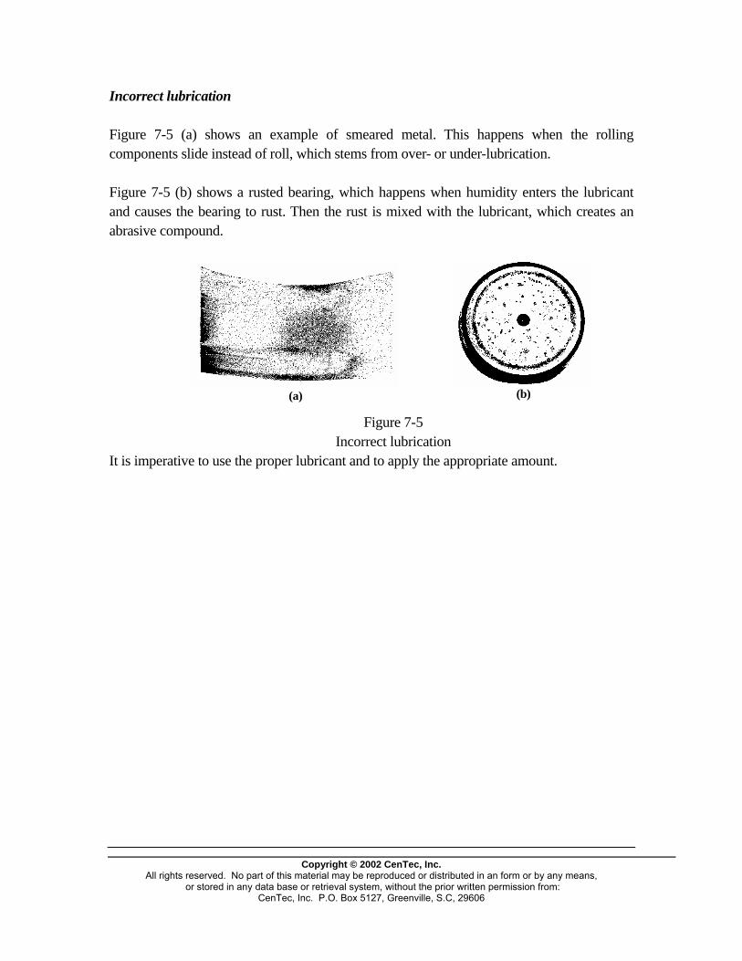
Incorrect lubrication Figure 7-5 (a) shows an example of smeared metal. This happens when the rolling components slide instead of roll, which stems from over- or under-lubrication. Figure 7-5 (b) shows a rusted bearing, which happens when humidity enters the lubricant and causes the bearing to rust. Then the rust is mixed with the lubricant, which creates an abrasive compound.
(a)
(b)
Figure 7-5 Incorrect lubrication It is imperative to use the proper lubricant and to apply the appropriate amount.
Copyright © 2002 CenTec, Inc.
All rights reserved. No part of this material may be reproduced or distributed in an form or by any means, or stored in any data base or retrieval system, without the prior written permission from:
CenTec, Inc. P.O. Box 5127, Greenville, S.C, 29606
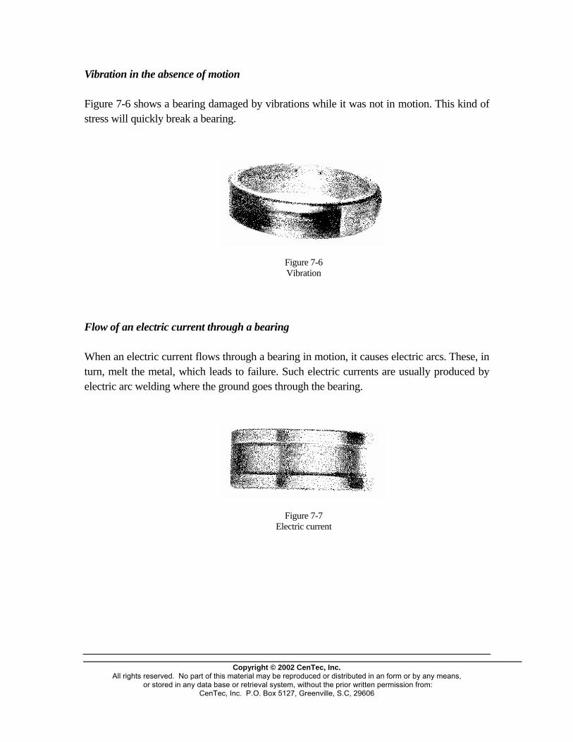
Vibration in the absence of motion Figure 7-6 shows a bearing damaged by vibrations while it was not in motion. This kind of stress will quickly break a bearing.
Figure 7-6 Vibration
Flow of an electric current through a bearing When an electric current flows through a bearing in motion, it causes electric arcs. These, in turn, melt the metal, which leads to failure. Such electric currents are usually produced by electric arc welding where the ground goes through the bearing.
Figure 7-7 Electric current
Copyright © 2002 CenTec, Inc.
All rights reserved. No part of this material may be reproduced or distributed in an form or by any means, or stored in any data base or retrieval system, without the prior written permission from:
CenTec, Inc. P.O. Box 5127, Greenville, S.C, 29606
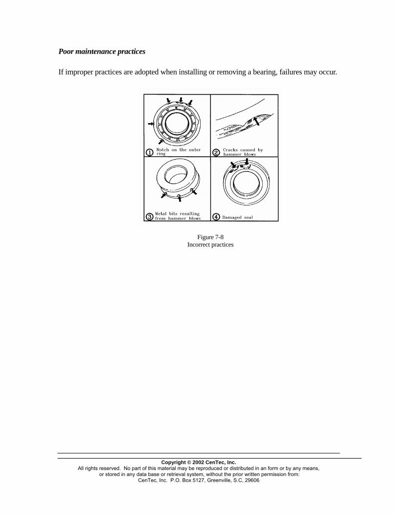
Poor maintenance practices If improper practices are adopted when installing or removing a bearing, failures may occur.
Figure 7-8 Incorrect practices
Copyright © 2002 CenTec, Inc.
All rights reserved. No part of this material may be reproduced or distributed in an form or by any means, or stored in any data base or retrieval system, without the prior written permission from:
CenTec, Inc. P.O. Box 5127, Greenville, S.C, 29606
Consequences of too small or too worn a shaft
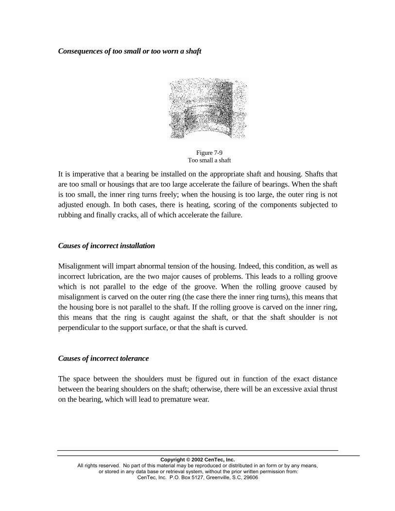
Figure 7-9 Too small a shaft
It is imperative that a bearing be installed on the appropriate shaft and housing. Shafts that are too small or housings that are too large accelerate the failure of bearings. When the shaft is too small, the inner ring turns freely; when the housing is too large, the outer ring is not adjusted enough. In both cases, there is heating, scoring of the components subjected to rubbing and finally cracks, all of which accelerate the failure. Causes of incorrect installation Misalignment will impart abnormal tension of the housing. Indeed, this condition, as well as incorrect lubrication, are the two major causes of problems. This leads to a rolling groove which is not parallel to the edge of the groove. When the rolling groove caused by misalignment is carved on the outer ring (the case there the inner ring turns), this means that the housing bore is not parallel to the shaft. If the rolling groove is carved on the inner ring, this means that the ring is caught against the shaft, or that the shaft shoulder is not perpendicular to the support surface, or that the shaft is curved. Causes of incorrect tolerance The space between the shoulders must be figured out in function of the exact distance between the bearing shoulders on the shaft; otherwise, there will be an excessive axial thrust on the bearing, which will lead to premature wear.
Copyright © 2002 CenTec, Inc.
All rights reserved. No part of this material may be reproduced or distributed in an form or by any means, or stored in any data base or retrieval system, without the prior written permission from:
CenTec, Inc. P.O. Box 5127, Greenville, S.C, 29606

Cylindrical roller Single row ball thrust
Spherical roller Double row angular contact ball Single row maxi ball
Tapered roller Single row angular Contact ball Single row ball
Double row
Copyright © 2002 CenTec, Inc.
All rights reserved. No part of this material may be reproduced or distributed in an form or by any means, or stored in any data base or retrieval system, without the prior written permission from:
CenTec, Inc. P.O. Box 5127, Greenville, S.C, 29606

Double row self aligning ball Double row ball thrust Needle
Copyright © 2002 CenTec, Inc.
All rights reserved. No part of this material may be reproduced or distributed in an form or by any means, or stored in any data base or retrieval system, without the prior written permission from:
CenTec, Inc. P.O. Box 5127, Greenville, S.C, 29606

BELTS AND PULLEYS
Copyright © 2002 CenTec, Inc.
All rights reserved. No part of this material may be reproduced or distributed in an form or by any means, or stored in any data base or retrieval system, without the prior written permission from:
CenTec, Inc. P.O. Box 5127, Greenville, S.C, 29606

CATEGORIES OF BELTS AND PULLEYS Belt drive
Figure 1-1 Set of pulleys and belt
The pulley-belt system is one of the most ancient means of power transmission. At first, the belt was made of rope and the pulleys were made of wood. Today's belts and pulleys are vastly different and made to fit modern equipment requirements. The basic principle of the belt system is that the transfer of energy is achieved through the friction between the pulley and the belt. This friction is obtained by keeping the belt under tension.
Copyright © 2002 CenTec, Inc.
All rights reserved. No part of this material may be reproduced or distributed in an form or by any means, or stored in any data base or retrieval system, without the prior written permission from:
CenTec, Inc. P.O. Box 5127, Greenville, S.C, 29606

Advantages and disadvantages of a belt drive Belt drives are used extensively in industrial processes. However, this type of transmission must be selected after careful analysis of its advantages and disadvantages.
dV
Joined V Flat
Advantages: - shock absorbtion of sudden changes; - durability; - ease of installation and maintenance; - flexibility; - allowance for variations in speed; - relatively cheap; - silent operation; - no lubrication. Disadvantages: - heat generation; - frequent adjustments needed; - slip; - lengthening of the belt; - rapid wear when improperly positioned. NOTE: Though belts resist heat, oil and grease quite well, it is best to check with the manufacturer as to compatibility. These various points are the basis for determining when it is best to use belt-drive devices. They are used, for instance, when: - the distance between centers is too great for a chain or a gear me - slip does not matter much; - silent and flexible transmission is indicated. Construction of a belt
Figure 1-2
Copyright © 2002 CenTec, Inc.
All rights reserved. No part of this material may be reproduced or distributed in an f or stored in any data base or retrieval system, without the prior written per
CenTec, Inc. P.O. Box 5127, Greenville, S.C, 29606
Efforts within a belt Belts are usually made of rubber. They are designed to bear three types o
Classical
Narrow V
Notched
chanism;
Tension zone
orm or by any means, mission from:
Traction zone
Compression zone
f efforts. The inside
Variable spee
V-ribbed
Synchronous
part

Copyright © 2002 CenTec, Inc.
All rights reserved. No part of this material may be reproduced or distributed in an form or by any means, or stored in any data base or retrieval system, without the prior written permission from:
CenTec, Inc. P.O. Box 5127, Greenville, S.C, 29606
must be able to support compression forces since it is compressed when it encounters the pulley. The core part is not compressible and does not stretch. However, this is where the traction applied to the belt to prevent slip is supported. This is also the part to which string or rope is added to help withstand these efforts. The top part of the belt stretches to conform to the shape of the pulley. Therefore, the belt must be made in such a way as to support all these forces.

Types of belts
Copyright © 2002 CenTec, Inc.
All rights reserved. No part of this material may be reproduced or distributed in an form or by any means, or stored in any data base or retrieval system, without the prior written permission from:
CenTec, Inc. P.O. Box 5127, Greenville, S.C, 29606
Belts come in numerous cross sections. Figure 1-3 shows the most popular ones.
Figure 1-3 Types of belts
Round belts Round belts were inspired by the first rope belts. Today, they are made of solid rubber or of cord-reinforced rubber. This type of belt is not designed to support heavy loads since its contact surface is limited.
Figure 1-4 Area of contact
This type of belt is used on small machines, such as VCRs and computers.
Flat belts Flat belts are used less and less since they require wider pulleys, which takes more room. Flat belts are more commonly used with machines that develop a lot of power. Such belts will slip when there is an overload, thus they can be used as clutching devices. They are often made of cord-reinforced rubber which imparts robustness, adherence and good stretching properties. They can also be made of leather or fabric. NOTE: Flat belts can also be used as belt conveyors, where the belt is also the conveyor band. V-belts
Copyright © 2002 CenTec, Inc.
All rights reserved. No part of this material may be reproduced or distributed in an form or by any means, or stored in any data base or retrieval system, without the prior written permission from:
CenTec, Inc. P.O. Box 5127, Greenville, S.C, 29606
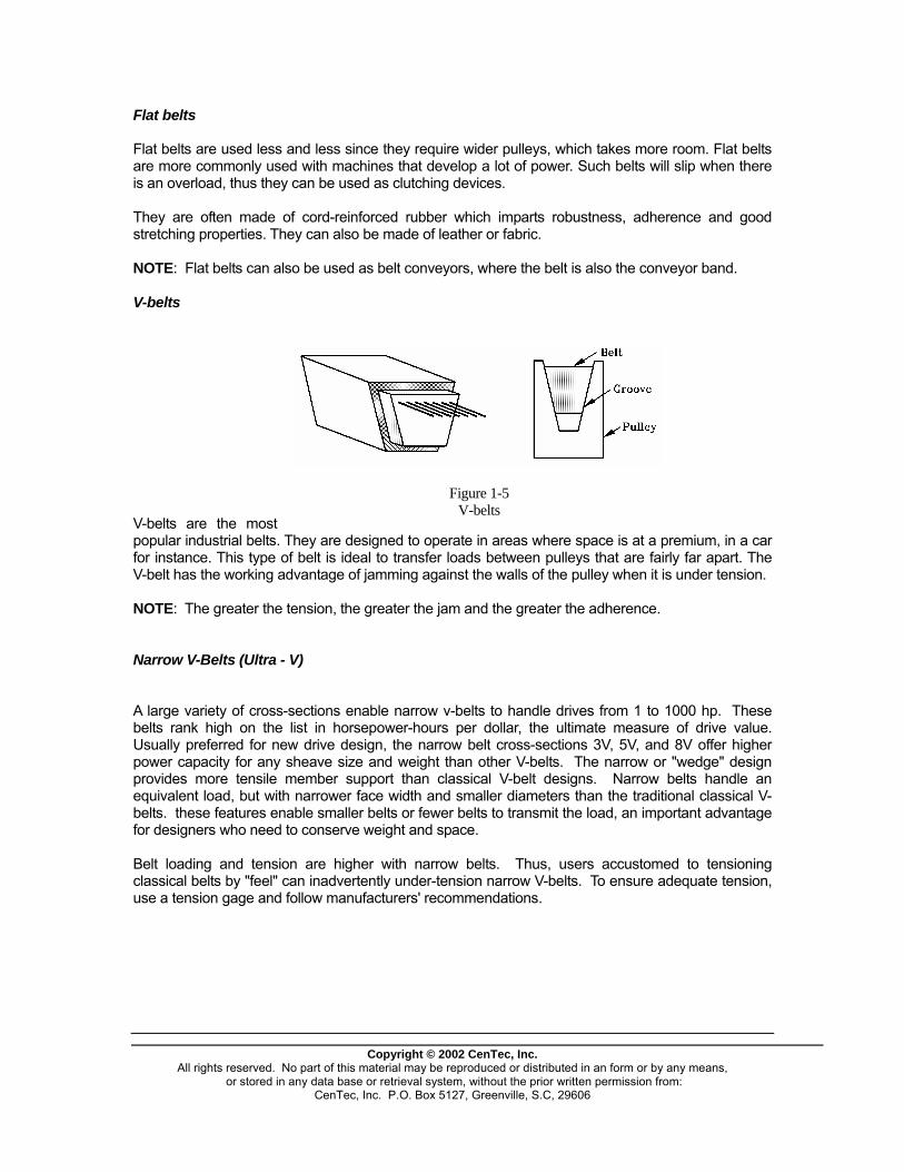
V-belts are the most popular industrial belts. They are designed to operate in areas where space is at a premium, in a car for instance. This type of belt is ideal to transfer loads between pulleys that are fairly far apart. The V-belt has the working advantage of jamming against the walls of the pulley when it is under tension.
Figure 1-5 V-belts
NOTE: The greater the tension, the greater the jam and the greater the adherence. Narrow V-Belts (Ultra - V) A large variety of cross-sections enable narrow v-belts to handle drives from 1 to 1000 hp. These belts rank high on the list in horsepower-hours per dollar, the ultimate measure of drive value. Usually preferred for new drive design, the narrow belt cross-sections 3V, 5V, and 8V offer higher power capacity for any sheave size and weight than other V-belts. The narrow or "wedge" design provides more tensile member support than classical V-belt designs. Narrow belts handle an equivalent load, but with narrower face width and smaller diameters than the traditional classical V-belts. these features enable smaller belts or fewer belts to transmit the load, an important advantage for designers who need to conserve weight and space. Belt loading and tension are higher with narrow belts. Thus, users accustomed to tensioning classical belts by "feel" can inadvertently under-tension narrow V-belts. To ensure adequate tension, use a tension gage and follow manufacturers' recommendations.

Classical V-Belts (Prime Movers) The most popular V-belt are A, B, C, D, and E classical belts. These belts are capable of handling fractional to 500 HP drives, usually at lowest cost. They occupy more space, and the drives weigh more that narrow belt drives. Also, classical belts are usually less efficient than narrow belts. However, their versatility and wide range of sizes and types will ensure that classical belts remain the dominant type. For several reasons, classical belts are still chosen for new drives when space and weight are not critical: - Familiarity and trust based on long successful use. - High tolerance for unusual drive conditions such as reverse bend, clutching, quarter turn,
and V-flat - Best tolerance for poor operating conditions and environment, or infrequent maintenance. Many classical belts are used for replacement because it is too costly to replace sheaves when upgrading from classical to narrow or other belt types
Figure 1-6 Classification of V-belts
Classical V-belts have a standard classification which allows one to quickly identify the maximum specific dimensions of a belt. Light-duty single V-Belts The 3L, 4L, and 5L light-duty belts are part of the classical belt line. Only in the U.S. and countries that have adopted U.S. standards do 4L and 5L belts exist. Other countries recognize only the equivalent classical belts, A and B section. Equivalents to 3L belts, designated M or Z, are found in global markets as an extension of the A, B, C, and D line. As the name implies, these belts are used singly on drives generally in the 1 HP or less category. However, in general distribution as opposed to OE use, the same A-B combination groove sheaves are used for 4L and 5L belts. Thus, the belts are frequently used in sets of two or three. Because these belts are not matched for such use, the practice is not recommended. Many large volume OE applications used fhp belts of special construction to carry 1hp or more for limited periods of time (up to 12 or 14 hp for lawn and garden tractors). Obtain replacements for this type of belt form the equipment manufacturer.
Copyright © 2002 CenTec, Inc.
All rights reserved. No part of this material may be reproduced or distributed in an form or by any means, or stored in any data base or retrieval system, without the prior written permission from:
CenTec, Inc. P.O. Box 5127, Greenville, S.C, 29606

Joined V-belts
Copyright © 2002 CenTec, Inc.
All rights reserved. No part of this material may be reproduced or distributed in an form or by any means, or stored in any data base or retrieval system, without the prior written permission from:
CenTec, Inc. P.O. Box 5127, Greenville, S.C, 29606
Joined V-belts are made of a number of V-belts which are linked together by a vulvanised tie strip. This kind of belt allows for a stable assembly and helps reduce vibrations during operation. Thus, problems of slap, flipping and slip are avoided. The tension to be applied to a joined V-belt is the same as that applied to a regular V-belt of same dimension.
Figure 1-7 Joined V-belt
Linked belts
Figure 1-8 Link belt
Link belts are made of a number of links held together by rivets. The length is modified by adding or withdrawing links. This kind of belt is ideal when the distance between the centres of pulleys is permanent. Its characteristics are comparable to those of V-belts, except for speed and load, which are not as great.
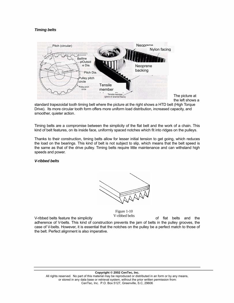
Timing belts
Copyright © 2002 CenTec,
All rights reserved. No part of this material may be reproduced or or stored in any data base or retrieval system, without th
CenTec, Inc. P.O. Box 5127, Greenvill
standard trapezoidal tooth timing belt where the picture at the
iming belts are a compromise between the simplicity of the
hanks to their construction, timing belts allow for lesser ini
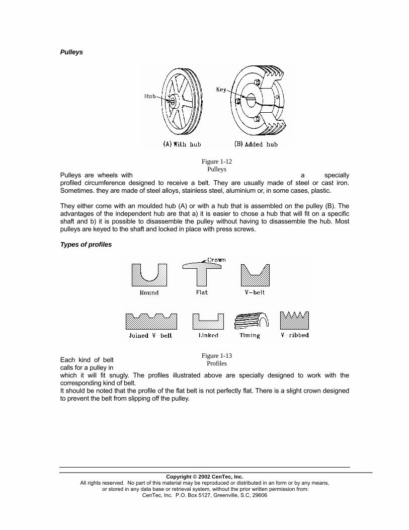
-ribbed belts
-ribbed belts feature the simplicity o
Drive). Its more circular tooth form offers more uniform load dsmoother, quieter action.
Pitch (circular)
pitch
ne Outside Dia.
Pitch Dia.
)
Tkind of belt features, on its inside face, uniformly spaced notc Tthe load on the bearings. This kind of belt is not subject to sthe same as that of the drive pulley. Timing belts require littspeeds and power. V Vadherence of V-belts. This kind of ccase of V-belts. However, it is essential that the notches on tthe belt. Perfect alignment is also imperative.
nstruction prevents the
Figure 1-10
V-ribbed belts
Neoprene
Inc. distributee prior wrie, S.C, 29
right sh
flat bel
tial tensi
istributio
Neoprebacking
hes whic
lip, whicle mainte
he pulley jam of
Nylon facing
ne
Tensile member ( l fib
Belt li
Pulley pitch circle
d in an form or by any means, tten permission from: 606
ows a HTD belt
t and the work of a chain. This
on to get going, which reduces
of flat belts and the lts u ,
The picture at the left shows a (High Torque
n, increased capacity, and
h fit into ridges on the pulleys.
h means that the belt speed is nance and can withstand high
in the p lley grooves the be a perfect match to those of be

Copyright © 2002 CenTec, Inc.
All rights reserved. No part of this material may be reproduced or distributed in an form or by any means, or stored in any data base or retrieval system, without the prior written permission from:
CenTec, Inc. P.O. Box 5127, Greenville, S.C, 29606
FLAT
BELT
V-BELT JOINED V-BELT
TIMING BELT
V-RIBBED BELT
LINKED BELT
PRESSURE ON BEARINGS
Very high Low Low Very low High Average
IDEAL FT/Min SPEED M/Min
1000 to 10,000
300 to 3000
1000 to 10,000
300 to 3000
1000 to 5000 300 to 1525
1000 to 10,000 300 to 3000
1000 to 6000 300 to 1830
1000 to 5000
300 to 1525
PERFORMANCE 5000 FT/Min 1525 M/Min and less
Good
Pass
Not recom-
mended
Good
Pass
Pass
PERFORMANCE 1000 FT/Min 300 M/Min and less
Pass
Pass
Pass
Good
Pass
Pass
RESISTANCE TO LOAD JOLTS
Good
Good
Good
Pass
Good
Good
MECHANICAL EFFICIENCY
Good
Good
Good
Perfect
Good
Good
TOLERANCE TO MISALIGNMENTS
No Yes Yes No No Yes
RESISTANCE TO WEAR
Good Not as good Not as good Good Good Good
QUIET OPERATION
Excellent Very good Good Good Good Good
SYNCHRONISM OF MECHANISMS
No No No Yes No No
SLIP Slight Negligible Slight None Slight Slight
PURCHASE PRICE
Low Low Moderate Moderate Moderate Low
RESISTANCE TO TEMPERATURE
Good Good Not as good Good Good Good
MAINTENANCE Minimal Negligible Minimal Negligible Minimal Minimal Figure 1-11 Characteristics of belts Chart 1-11 gives the characteristics that are useful when choosing a belt.
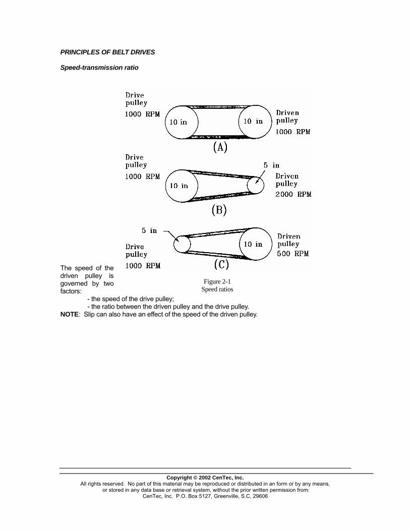
Pulleys
Copyright © 2002 CenTec, Inc.
All rights reserved. No part of this material may be reproduced or distributed in an form or by any means, or stored in any data base or retrieval system, without the prior written permission from:
CenTec, Inc. P.O. Box 5127, Greenville, S.C, 29606
Pulleys are wheels with a specially profiled circumference designed to receive a belt. They are usually made of steel or cast iron. Sometimes. they are made of steel alloys, stainless steel, aluminium or, in some cases, plastic.
Figure 1-12 Pulleys
They either come with an moulded hub (A) or with a hub that is assembled on the pulley (B). The advantages of the independent hub are that a) it is easier to chose a hub that will fit on a specific shaft and b) it is possible to disassemble the pulley without having to disassemble the hub. Most pulleys are keyed to the shaft and locked in place with press screws. Types of profiles Each kind of belt calls for a pulley in which it will fit snugly. The profiles illustrated above are specially designed to work with the corresponding kind of belt.
Figure 1-13 Profiles
It should be noted that the profile of the flat belt is not perfectly flat. There is a slight crown designed to prevent the belt from slipping off the pulley.
PRINCIPLES OF BELT DRIVES Speed-transmission ratio
Figure 2-1 Speed ratios
The speed of the driven pulley is governed by two factors: - the speed of the drive pulley; - the ratio between the driven pulley and the drive pulley. NOTE: Slip can also have an effect of the speed of the driven pulley.
Copyright © 2002 CenTec, Inc.
All rights reserved. No part of this material may be reproduced or distributed in an form or by any means, or stored in any data base or retrieval system, without the prior written permission from:
CenTec, Inc. P.O. Box 5127, Greenville, S.C, 29606
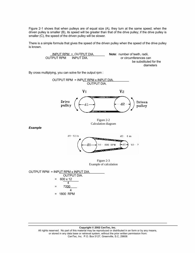
Figure 2-1 shows that when pulleys are of equal size (A), they turn at the same speed; when the driven pulley is smaller (B), its speed will be greater than that of the drive pulley; if the drive pulley is smaller (C), the speed of the driven pulley will be slower. There is a simple formula that gives the speed of the driven pulley when the speed of the drive pulley is known. INPUT RPM = OUTPUT DIA. Note: number of teeth, radii, OUTPUT RPM INPUT DIA. or circumferences can be substituted for the diameters
Copyright © 2002 CenTec, Inc.
All rights reserved. No part of this material may be reproduced or distributed in an form or by any means, or stored in any data base or retrieval system, without the prior written permission from:
CenTec, Inc. P.O. Box 5127, Greenville, S.C, 29606
By cross multiplying, you can solve for the output rpm : OUTPUT RPM = INPUT RPM x INPUT DIA. OUTPUT DIA. Example OUTPUT RPM = INPUT RPM x INPUT DIA. OUTPUT DIA. = 600 x 12 4 = 7200
Figure 2-2 Calculation diagram
Figure 2-3 Example of calculation
4 = 1800 RPM
Variable-speed pulley
Copyright © 2002 CenTec, Inc.
All rights reserved. No part of this material may be reproduced or distributed in an form or by any means, or stored in any data base or retrieval system, without the prior written permission from:
CenTec, Inc. P.O. Box 5127, Greenville, S.C, 29606
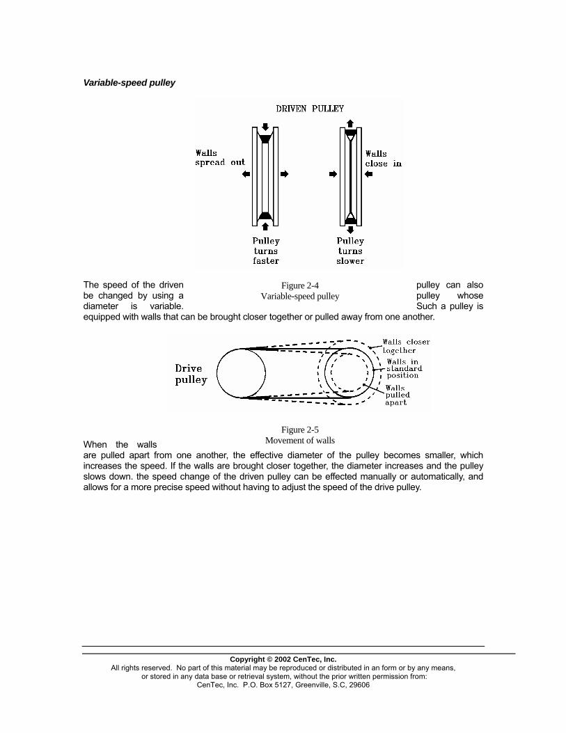
The speed of the driven pulley can also be changed by using a pulley whose diameter is variable. Such a pulley is equipped with walls that can be brought closer together or pulled away from one another.
Figure 2-4 Variable-speed pulley
When the walls are pulled apart from one another, the effective diameter of the pulley becomes smaller, which increases the speed. If the walls are brought closer together, the diameter increases and the pulley slows down. the speed change of the driven pulley can be effected manually or automatically, and allows for a more precise speed without having to adjust the speed of the drive pulley.
Figure 2-5 Movement of walls

NOTE: It is also possible to use a variable-diameter pulley on the drive pulley. It should be noted that a change in the diameter of the driven pulley will cause a change in the belt tension. This problem can be resolved by changing the distance between the pulleys by having one of them spring loaded. It is also possible to use an idler pulley to maintain constant tension.The last solution consists in using two variable-diameter pulleys to allow for automatic compensation of the increase in one pulley by a decrease in the other. Transmitted power
Copyright © 2002 CenTec, Inc.
All rights reserved. No part of this material may be reproduced or distributed in an form or by any means, or stored in any data base or retrieval system, without the prior written permission from:
CenTec, Inc. P.O. Box 5127, Greenville, S.C, 29606
Speed is not the only factor to take into account, power transmission also matters. The ratio between the diameters of the two pulleys must be at most 3-1 to avoid belt slip.
Figure 2-6 Power transmission
The contact arc between the pulley and the belt must be sufficient to support the belt and avoid slip. The greater the ratio, the smaller the arc of contact, which will reduce resistance to effort. NOTE: The arc of contact will increase slightly as the distance between the shafts increases.
Step drive
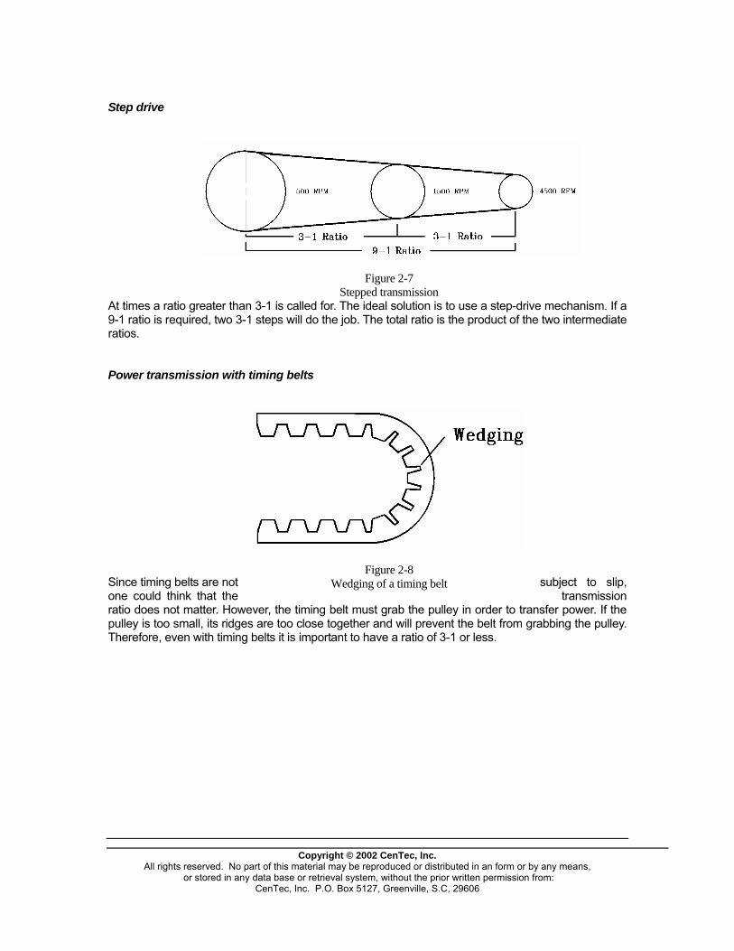
At times a ratio greater than 3-1 is called for. The ideal solution is to use a step-drive mechanism. If a 9-1 ratio is required, two 3-1 steps will do the job. The total ratio is the product of the two intermediate ratios.
Figure 2-7 Stepped transmission
Power transmission with timing belts
Copyright © 2002 CenTec, Inc.
All rights reserved. No part of this material may be reproduced or distributed in an form or by any means, or stored in any data base or retrieval system, without the prior written permission from:
CenTec, Inc. P.O. Box 5127, Greenville, S.C, 29606
Since timing belts are not subject to slip, one could think that the transmission ratio does not matter. However, the timing belt must grab the pulley in order to transfer power. If the pulley is too small, its ridges are too close together and will prevent the belt from grabbing the pulley. Therefore, even with timing belts it is important to have a ratio of 3-1 or less.
Figure 2-8 Wedging of a timing belt

Tension jacks
Figure 2-9 Idler pulleys
Idler pulleys are auxiliary pulleys whose purpose is to increase the tension in the belt to prevent slip. They are also called into play to go around an obstacle or to serve as support when the distance between two pulleys is too great. Idler pulleys can be located in a number of places, but they should be positioned where they will have maximum efficiency. The best method (A) is to place the idler pulley on the slack side of the belt, downstream from the drive pulley, on the outer side of the belt and as close as possible to the drive pulley. This allows for a greater angle of wrap between the belt and the pulleys. The idler pulley can also be placed against the inner face of the belt (B) when the angle of wrap is not important (low load). When space is at a premium and position (A) is not possible, the idler pulley can be located on the taut segment of the belt. In such a case, it will have to be positioned close to the driven pulley (C and D). Here again, it is preferable to place the idler pulley on the outer side of the belt so as to increase the angle of wrap.
Copyright © 2002 CenTec, Inc.
All rights reserved. No part of this material may be reproduced or distributed in an form or by any means, or stored in any data base or retrieval system, without the prior written permission from:
CenTec, Inc. P.O. Box 5127, Greenville, S.C, 29606

Figuring out the length of a belt By figuring out the length of a belt, one can determine which type to use. This calculation can be done in a number of ways, but the following formula is preferred:
CdDdDxCL
4)()(57.12
2−+++=
where L = Length of the belt C = Distance between the Centers of the two pulleys D = Diameter of the large pulley d = diameter of the small pulley One can also use a table which gives the length that is needed.
CHART OF V-BELT LENGTH
L
Toength of the belt
tal diameters of the pulleys
4 4.5 5 5 5 .5 6 6.5 7 7.5 8 8.5 9 9.
4 16 4.9 .5 4.1
5 18 5.9 .5 5.1 4.4
6 20 6.9 .5 6.1 5.6 5.2
7 22 7.9 .5 7.1 6.6 6.2 5.8
8 24 8.9 .5 8.1 7.6 7.2 6.8 6.3 5.8
9 26 9.9 .5 9.1 8.6 8.2 7.8 7.3 6.9 6.6
0 1 28 10.9 1 .5 0.1 9.6 9.2 8.8 8.4 7.9 7.6 7.1 6 6.
1 1 130 11.9 1 .5 1.1 0.6 10.2 9.8 9.4 8.9 8.6 8.1 7 7. 7.3
32 12.9 12.5 1 11.6 11.2 10.8 10.4 10 9.6 9.1 7 8. 8.4 2.1
3 1 1 7 34 13.9 1 .5 3.1 2.7 12.2 11.8 11.4 11 10.6 10.2 9. 9.4
EXAMPLE If the distance between the centres of the pulleys is 10 inches and the pulleys have diameters of 3 and 4.5 inches respectively, what will be the length of the belt.
CdDdDxCL
4)()(57.12
2−+++=
104
)35.4()35.4(57.11022
xxxL −
+++=
8.31 ′′=L The chart would give 32 inches, which shows that the formula leads to a more precise result. However, the chart gives the belt lengths that are standard on the market. Angle of wrap
Copyright © 2002 CenTec, Inc.
All rights reserved. No part of this material may be reproduced or distributed in an form or by any means, or stored in any data base or retrieval system, without the prior written permission from:
CenTec, Inc. P.O. Box 5127, Greenville, S.C, 29606

Copyright © 2002 CenTec, Inc.
All rights reserved. No part of this material may be reproduced or distributed in an form or by any means, or stored in any data base or retrieval system, without the prior written permission from:
CenTec, Inc. P.O. Box 5127, Greenville, S.C, 29606
The angle of wrap is that part of the part of the pulley that is in contact with the belt. The greater the arc, the better power will be transferred between the pulleys, The angle of wrap can be figured out as follows:
Figure 2-10 Angle of wrap
Angle of wrap = 180 -60 (D-d) C where D= Diameter of the large pulley (inches) d = diameter of the small pulley (inches) C= Distance between the Centres of the pulleys (inches)
CORRECTION FACTOR CHART
Angle of wrap o wrap Correction fact r Angle of Correction
180� 170� 160� 150� 140�
1.00 .98 .95 .92 .89
130� 120� 110� 100� 90�
.86 .83 .79 .74 .69
This chart gives the correction that will need to be applied to the power carried by the belt depending on the angle of wrap. EXAMPLE A belt that can usually carry 20 hp of power and is on a system where the angle of wrap is 120 will be able to carry no more power than 20 hp x .83 = 16.6 hp.

PROBLEMS, CAUSES AND CORRECTIVE MEASURES Inspection
Copyright © 2002 CenTec, Inc.
All rights reserved. No part of this material may be reproduced or distributed in an form or by any means, or stored in any data base or retrieval system, without the prior written permission from:
CenTec, Inc. P.O. Box 5127, Greenville, S.C, 29606
The inspection of a belt is done either when it is in motion or at rest.
Figure 4-1
The inspection during operation allows to see how the belt-drive reacts to changes in speed and load. Points that can be observed during operation are: - belt slap; - squeaking and slip; - zigzags; - odour of burnt rubber NOTE : Never get to close to a belt or place your hands near it when the system is in operation. A visual inspection does not allow to pinpoint all breakages of problems. This is why the belt must be stopped occasionally to better inspect the various components.
Pulley inspection
Copyright © 2002 CenTec, Inc.
All rights reserved. No part of this material may be reproduced or distributed in an form or by any means, or stored in any data base or retrieval system, without the prior written permission from:
CenTec, Inc. P.O. Box 5127, Greenville, S.C, 29606
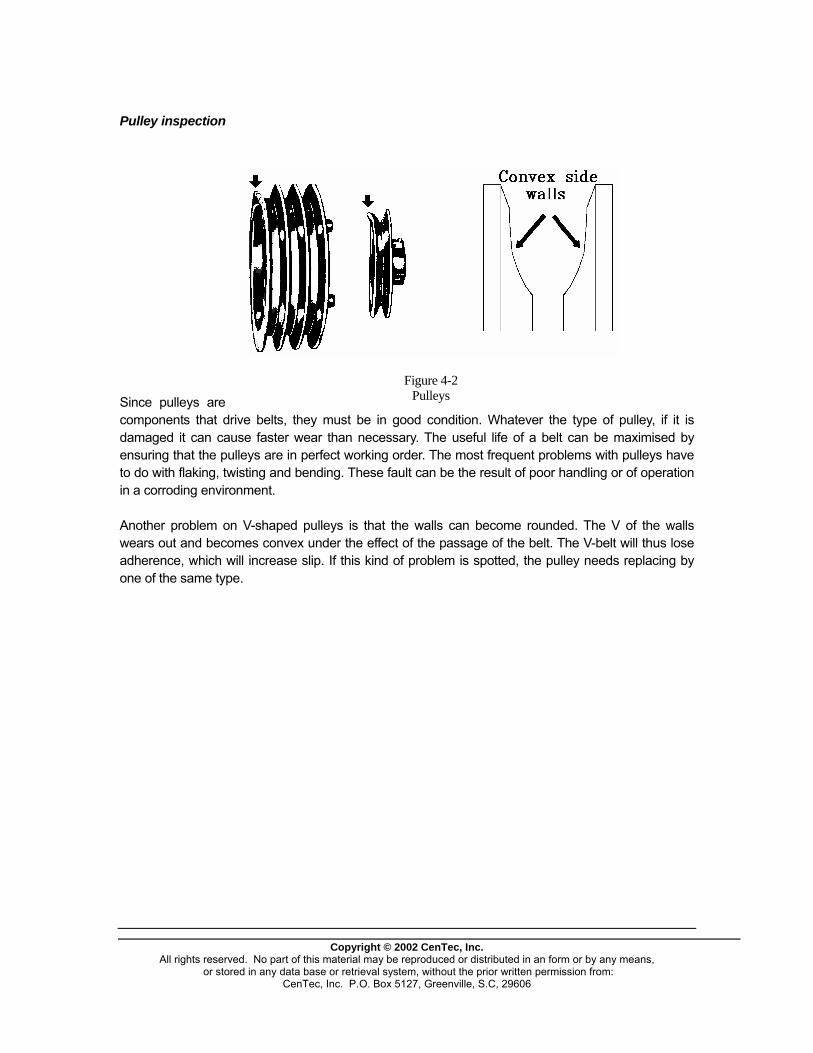
Since pulleys are components that drive belts, they must be in good condition. Whatever the type of pulley, if it is damaged it can cause faster wear than necessary. The useful life of a belt can be maximised by ensuring that the pulleys are in perfect working order. The most frequent problems with pulleys have to do with flaking, twisting and bending. These fault can be the result of poor handling or of operation in a corroding environment.
Figure 4-2 Pulleys
Another problem on V-shaped pulleys is that the walls can become rounded. The V of the walls wears out and becomes convex under the effect of the passage of the belt. The V-belt will thus lose adherence, which will increase slip. If this kind of problem is spotted, the pulley needs replacing by one of the same type.
Inspection of belts
Copyright © 2002 CenTec, Inc.
All rights reserved. No part of this material may be reproduced or distributed in an form or by any means, or stored in any data base or retrieval system, without the prior written permission from:
CenTec, Inc. P.O. Box 5127, Greenville, S.C, 29606
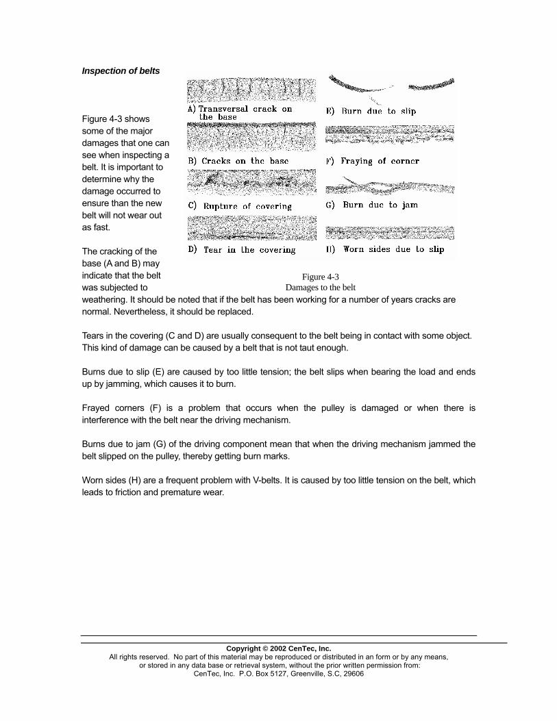
Figure 4-3 shows some of the major damages that one can see when inspecting a belt. It is important to determine why the damage occurred to ensure than the new belt will not wear out as fast. The cracking of the base (A and B) may indicate that the belt was subjected to weathering. It should be noted that if the belt has been working for a number of years cracks are normal. Nevertheless, it should be replaced.
Figure 4-3 Damages to the belt
Tears in the covering (C and D) are usually consequent to the belt being in contact with some object. This kind of damage can be caused by a belt that is not taut enough. Burns due to slip (E) are caused by too little tension; the belt slips when bearing the load and ends up by jamming, which causes it to burn. Frayed corners (F) is a problem that occurs when the pulley is damaged or when there is interference with the belt near the driving mechanism. Burns due to jam (G) of the driving component mean that when the driving mechanism jammed the belt slipped on the pulley, thereby getting burn marks. Worn sides (H) are a frequent problem with V-belts. It is caused by too little tension on the belt, which leads to friction and premature wear.
Copyright © 2002 CenTec, Inc.
All rights reserved. No part of this material may be reproduced or distributed in an form or by any means, or stored in any data base or retrieval system, without the prior written permission from:
CenTec, Inc. P.O. Box 5127, Greenville, S.C, 29606
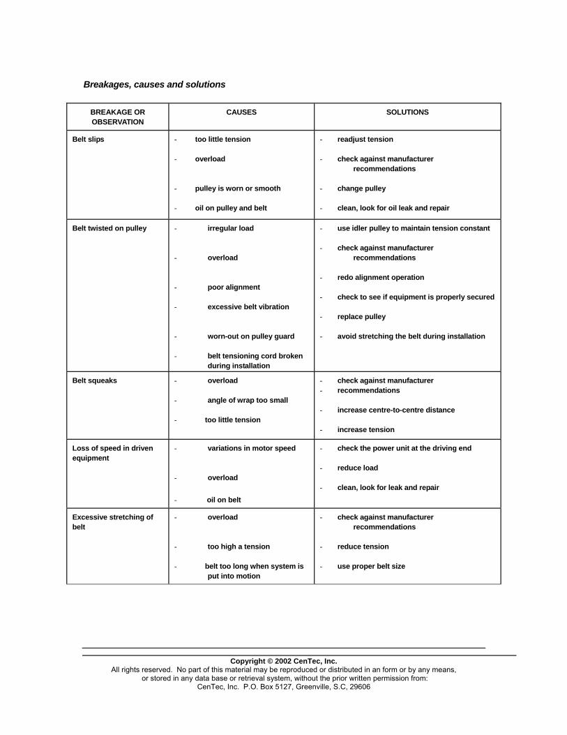
Breakages, causes and solutions
BREAKAGE OR OBSERVATION
CAUSES SOLUTIONS
Belt slips - too little tension - overload - pulley is worn or smooth - oil on pulley and belt
- readjust tension - check against manufacturer
recommendations - change pulley - clean, look for oil leak and repair
Belt twisted on pulley - irregular load - overload - poor alignment - excessive belt vibration - worn-out on pulley guard - belt tensioning cord broken
during installation
- use idler pulley to maintain tension constant - check against manufacturer
recommendations - redo alignment operation - check to see if equipment is properly secured - replace pulley - avoid stretching the belt during installation
Belt squeaks - overload - angle of wrap too small - too little tension
- check against manufacturer - recommendations - increase centre-to-centre distance - increase tension
Loss of speed in driven equipment
- variations in motor speed - overload - oil on belt
- check the power unit at the driving end - reduce load - clean, look for leak and repair
Excessive stretching of belt
- overload - too high a tension - belt too long when system is
put into motion
- check against manufacturer recommendations
- reduce tension - use proper belt size
Copyright © 2002 CenTec, Inc.
All rights reserved. No part of this material may be reproduced or distributed in an form or by any means, or stored in any data base or retrieval system, without the prior written permission from:
CenTec, Inc. P.O. Box 5127, Greenville, S.C, 29606
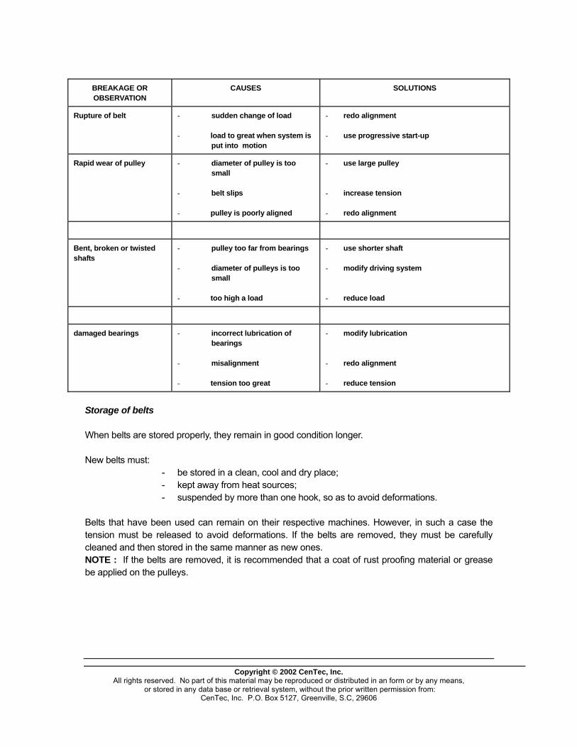
BREAKAGE OR OBSERVATION
CAUSES SOLUTIONS
Rupture of belt - sudden change of load - load to great when system is
put into motion
- redo alignment - use progressive start-up
Rapid wear of pulley - diameter of pulley is too small
- belt slips - pulley is poorly aligned
- use large pulley - increase tension - redo alignment
Bent, broken or twisted shafts
- pulley too far from bearings - diameter of pulleys is too
small - too high a load
- use shorter shaft - modify driving system - reduce load
damaged bearings - incorrect lubrication of bearings
- misalignment - tension too great
- modify lubrication - redo alignment - reduce tension
Storage of belts When belts are stored properly, they remain in good condition longer. New belts must: - be stored in a clean, cool and dry place; - kept away from heat sources; - suspended by more than one hook, so as to avoid deformations. Belts that have been used can remain on their respective machines. However, in such a case the tension must be released to avoid deformations. If the belts are removed, they must be carefully cleaned and then stored in the same manner as new ones. NOTE : If the belts are removed, it is recommended that a coat of rust proofing material or grease be applied on the pulleys.

GEARS
Copyright © 2002 CenTec, Inc.
All rights reserved. No part of this material may be reproduced or distributed in an form or by any means, or stored in any data base or retrieval system, without the prior written permission from:
CenTec, Inc. P.O. Box 5127, Greenville, S.C, 29606
Copyright © 2002 CenTec, Inc.
All rights reserved. No part of this material may be reproduced or distributed in an form or by any means, or stored in any data base or retrieval system, without the prior written permission from:
CenTec, Inc. P.O. Box 5127, Greenville, S.C, 29606
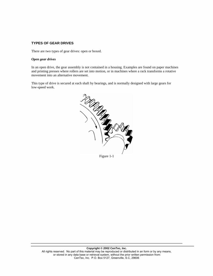
TYPES OF GEAR DRIVES There are two types of gear drives: open or boxed. Open gear drives In an open drive, the gear assembly is not contained in a housing. Examples are found on paper machines and printing presses where rollers are set into motion, or in machines where a rack transforms a rotative movement into an alternative movement. This type of drive is secured at each shaft by bearings, and is normally designed with large gears for low-speed work.
Figure 1-1
Copyright © 2002 CenTec, Inc.
All rights reserved. No part of this material may be reproduced or distributed in an form or by any means, or stored in any data base or retrieval system, without the prior written permission from:
CenTec, Inc. P.O. Box 5127, Greenville, S.C, 29606
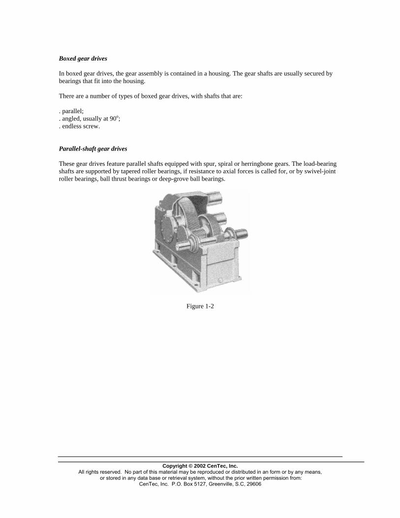
Boxed gear drives In boxed gear drives, the gear assembly is contained in a housing. The gear shafts are usually secured by bearings that fit into the housing. There are a number of types of boxed gear drives, with shafts that are: . parallel; . angled, usually at 90o; . endless screw. Parallel-shaft gear drives These gear drives feature parallel shafts equipped with spur, spiral or herringbone gears. The load-bearing shafts are supported by tapered roller bearings, if resistance to axial forces is called for, or by swivel-joint roller bearings, ball thrust bearings or deep-grove ball bearings.
Figure 1-2
Copyright © 2002 CenTec, Inc.
All rights reserved. No part of this material may be reproduced or distributed in an form or by any means, or stored in any data base or retrieval system, without the prior written permission from:
CenTec, Inc. P.O. Box 5127, Greenville, S.C, 29606

Types of gears used:
- spur gears,
Figure 1-3 - helical gears,
Figure 1-4
- herringbone gears,
Copyright © 2002 CenTec, Inc. All rights reserved. No part of this material may be reproduced or distributed in an form or by any means,
or stored in any data base or retrieval system, without the prior written permission from: CenTec, Inc. P.O. Box 5127, Greenville, S.C, 29606

Figure 1-5 When designing a parallel-shaft gear drive, the manufacturer takes into account the speed of operation, the speed-reduction ratio and the running torque. He is then in a position to choose the proper type of gears. Spur and helical gears offer 93 to 95% of mechanical efficiency, the rest being transformed into heat. Their assembly and disassembly, as well as adjustments, are usually quick and easy to do. The use of helical gears creates forces that are parallel to the axis. Helical gears are similar to spur gears, except that their teeth make a spiral around the body of the gear, rather than being parallel to the axis of the shaft. Two or more teeth are geared in at any given time. These gears produce an axial thrust in directions that are opposite to the direction of rotation. Herringbone gears are similar to helical gears. They are in fact two helical gears set back to back and welded together. This kind of gear eliminates axial forces created by the rotative movement.
- planetary gears.
Figure 1-6 Planetary gear
Planetary gears are systems which offer versatility in fairly confined spaces. They are three-part gears.
ANNULUS
PLANETARY
SATELLITES
Terminology Figure 1-7
The central gear, called the planetary gear, is surrounded by satellite gears. There are 2 to 5 such gears located symmetrically around the planetary gear. The annulus is the component which encircles the planetary gear. Fixed annulus Fixed planetary Fixed
satellites
Copyright © 2002 CenTec, Inc.
All rights reserved. No part of this material may be reproduced or distributed in an form or by any means, or stored in any data base or retrieval system, without the prior written permission from:
CenTec, Inc. P.O. Box 5127, Greenville, S.C, 29606
Copyright © 2002 CenTec, Inc.
All rights reserved. No part of this material may be reproduced or distributed in an form or by any means, or stored in any data base or retrieval system, without the prior written permission from:
CenTec, Inc. P.O. Box 5127, Greenville, S.C, 29606
Drive annulus
Reduction Ratio = A + B B
Overdrive in reverse
Ratio = A B
Drive planetary
Very high speed reduction Ratio = A + B A
Reverse
Ratio = B A
Drive satellites
Quick overdrive Ratio = A A + B
Overdrive Ratio = B A + B
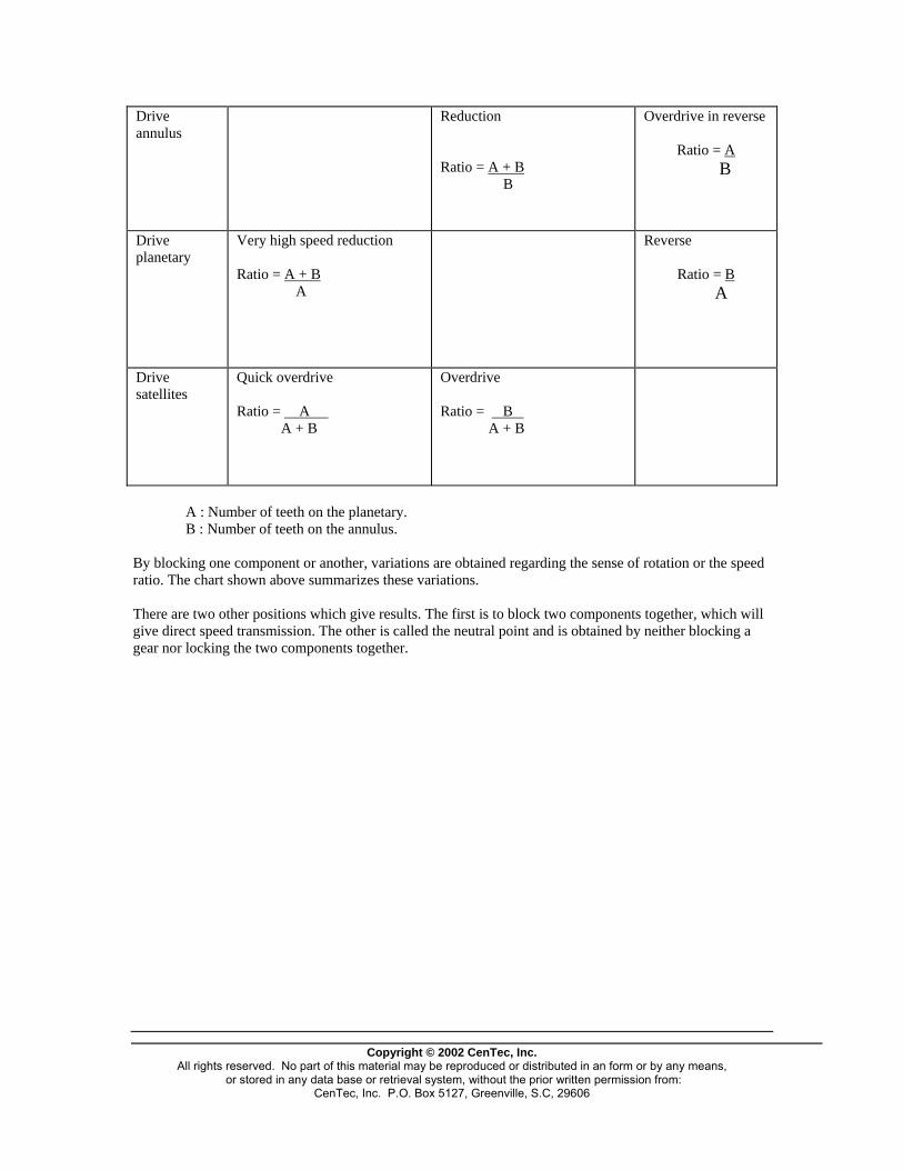
A : Number of teeth on the planetary. B : Number of teeth on the annulus. By blocking one component or another, variations are obtained regarding the sense of rotation or the speed ratio. The chart shown above summarizes these variations. There are two other positions which give results. The first is to block two components together, which will give direct speed transmission. The other is called the neutral point and is obtained by neither blocking a gear nor locking the two components together.
Right-angle gear drives The shafts of these drives are positioned at right angle to each other, usually in the same plane. The teeth are straight or spiral, or hypoid (when the shafts are not in the same plane).
Figure 1-8
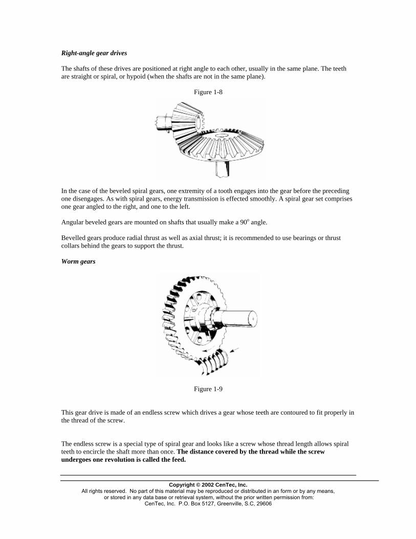
In the case of the beveled spiral gears, one extremity of a tooth engages into the gear before the preceding one disengages. As with spiral gears, energy transmission is effected smoothly. A spiral gear set comprises one gear angled to the right, and one to the left. Angular beveled gears are mounted on shafts that usually make a 90o angle. Bevelled gears produce radial thrust as well as axial thrust; it is recommended to use bearings or thrust collars behind the gears to support the thrust. Worm gears
Figure 1-9
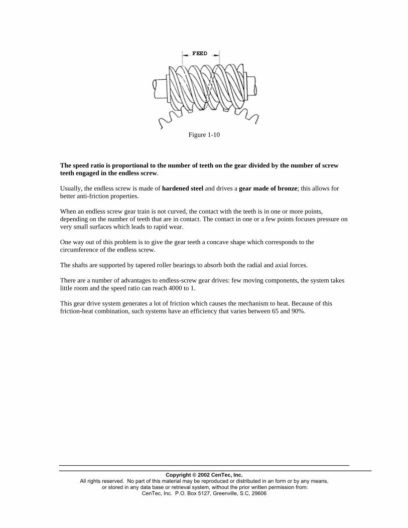
This gear drive is made of an endless screw which drives a gear whose teeth are contoured to fit properly in the thread of the screw. The endless screw is a special type of spiral gear and looks like a screw whose thread length allows spiral teeth to encircle the shaft more than once. The distance covered by the thread while the screw undergoes one revolution is called the feed.
Copyright © 2002 CenTec, Inc.
All rights reserved. No part of this material may be reproduced or distributed in an form or by any means, or stored in any data base or retrieval system, without the prior written permission from:
CenTec, Inc. P.O. Box 5127, Greenville, S.C, 29606
FEED
Figure 1-10
The speed ratio is proportional to the number of teeth on the gear divided by the number of screw teeth engaged in the endless screw. Usually, the endless screw is made of hardened steel and drives a gear made of bronze; this allows for better anti-friction properties. When an endless screw gear train is not curved, the contact with the teeth is in one or more points, depending on the number of teeth that are in contact. The contact in one or a few points focuses pressure on very small surfaces which leads to rapid wear. One way out of this problem is to give the gear teeth a concave shape which corresponds to the circumference of the endless screw. The shafts are supported by tapered roller bearings to absorb both the radial and axial forces. There are a number of advantages to endless-screw gear drives: few moving components, the system takes little room and the speed ratio can reach 4000 to 1. This gear drive system generates a lot of friction which causes the mechanism to heat. Because of this friction-heat combination, such systems have an efficiency that varies between 65 and 90%.
Copyright © 2002 CenTec, Inc.
All rights reserved. No part of this material may be reproduced or distributed in an form or by any means, or stored in any data base or retrieval system, without the prior written permission from:
CenTec, Inc. P.O. Box 5127, Greenville, S.C, 29606

COMPONENTS OF A SPEED REDUCER AND THEIR RESPECTIVE POSITIONS
Oil gauge
Upper part
of housing
Driven
shaft
Adjustmentcap forexpansionplay
Lowerpart of housing
Spiral gear
Bevelledgear
Bushings
Driveshaft
Oil tank
Drain plug Figure 2-1
Lower part of housing The lower part of the speed reducer is designed to support the various sets of gears and to serve as an oil reservoir. It must be able to remain leak free despite vibrations. Shaft The drive shaft is normally smaller than the driven shaft. It is coupled to the motor and turns at the same speed as the motor.
Copyright © 2002 CenTec, Inc.
All rights reserved. No part of this material may be reproduced or distributed in an form or by any means, or stored in any data base or retrieval system, without the prior written permission from:
CenTec, Inc. P.O. Box 5127, Greenville, S.C, 29606
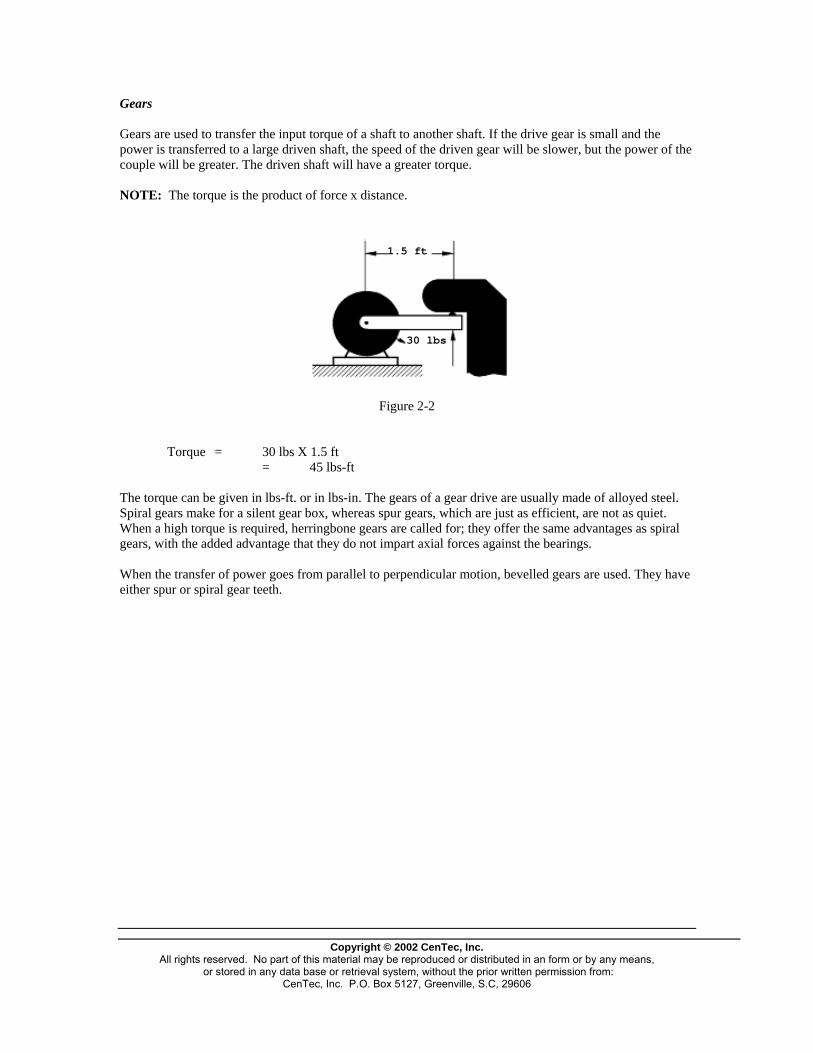
Gears Gears are used to transfer the input torque of a shaft to another shaft. If the drive gear is small and the power is transferred to a large driven shaft, the speed of the driven gear will be slower, but the power of the couple will be greater. The driven shaft will have a greater torque. NOTE: The torque is the product of force x distance.
1.5 ft
30 lbs
Figure 2-2
Torque = 30 lbs X 1.5 ft = 45 lbs-ft The torque can be given in lbs-ft. or in lbs-in. The gears of a gear drive are usually made of alloyed steel. Spiral gears make for a silent gear box, whereas spur gears, which are just as efficient, are not as quiet. When a high torque is required, herringbone gears are called for; they offer the same advantages as spiral gears, with the added advantage that they do not impart axial forces against the bearings. When the transfer of power goes from parallel to perpendicular motion, bevelled gears are used. They have either spur or spiral gear teeth.
Copyright © 2002 CenTec, Inc.
All rights reserved. No part of this material may be reproduced or distributed in an form or by any means, or stored in any data base or retrieval system, without the prior written permission from:
CenTec, Inc. P.O. Box 5127, Greenville, S.C, 29606
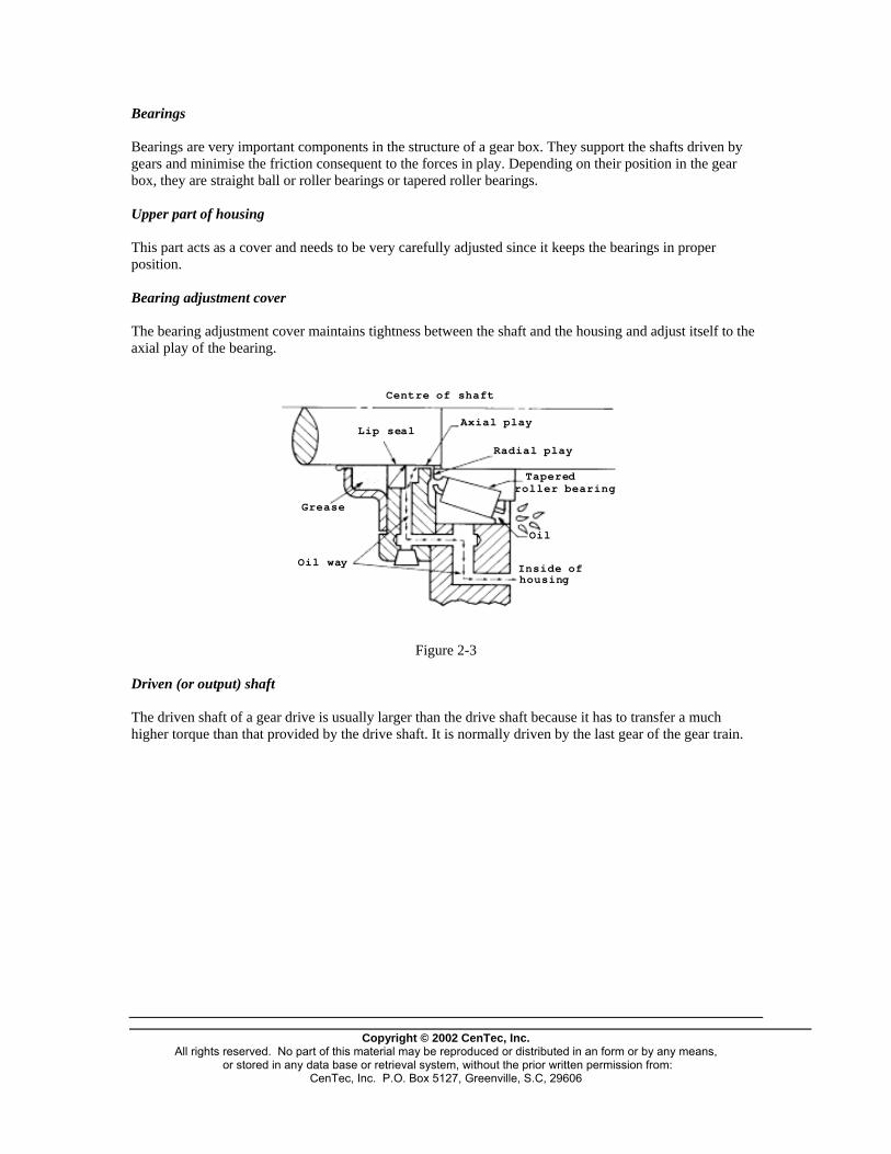
Bearings Bearings are very important components in the structure of a gear box. They support the shafts driven by gears and minimise the friction consequent to the forces in play. Depending on their position in the gear box, they are straight ball or roller bearings or tapered roller bearings. Upper part of housing This part acts as a cover and needs to be very carefully adjusted since it keeps the bearings in proper position. Bearing adjustment cover The bearing adjustment cover maintains tightness between the shaft and the housing and adjust itself to the axial play of the bearing.
Centre of shaft
Axial playLip seal
Radial play
Taperedroller bearing
Grease
Oil
Oil way Inside ofhousing
Figure 2-3
Driven (or output) shaft The driven shaft of a gear drive is usually larger than the drive shaft because it has to transfer a much higher torque than that provided by the drive shaft. It is normally driven by the last gear of the gear train.
Copyright © 2002 CenTec, Inc.
All rights reserved. No part of this material may be reproduced or distributed in an form or by any means, or stored in any data base or retrieval system, without the prior written permission from:
CenTec, Inc. P.O. Box 5127, Greenville, S.C, 29606

Oil gauge It often happens in plants that workers will eventually break the dip stick. This instrument is important because a lack of oil in a gear drive will quickly lead to overheating and component failure. Worm gear
Wormgear
Gear
Figure 2-4
The worm gear stands out by its reduction mechanism and 90o transfer principle. Here conventional bevelled gears are replaced by an endless screw and a gear.
Copyright © 2002 CenTec, Inc.
All rights reserved. No part of this material may be reproduced or distributed in an form or by any means, or stored in any data base or retrieval system, without the prior written permission from:
CenTec, Inc. P.O. Box 5127, Greenville, S.C, 29606

Endless screw As mentioned, the endless screw looks like a screw whose thread is long enough for the spiral teeth to go around the shaft more than once. It is made of steel and must have a perfect surface finish since it drives a gear made of softer alloy. Given its particular configuration, it heats up quite a lot and expands, a factor which must be taken into consideration when assembling the gear drive. Lubrication must be permanent to minimize friction between the worm screw and the gear. Gear The gear in this kind of gear drive has a very particular shape because of the contact it must maintain with the endless screw.
Figure 2-5
The teeth of this gear are concave on the support side and at the bottom of each groove. For small gear drives, the alloy used is bronze;, for larger ones, cast iron is used with an attached bronze crown. The shaft supporting the gear is set on tapered roller bearings so as to better resist the strong axial forces generated by this type of gear drive. Because of the amount of heat generated, it is very important that the gear drive be properly lubricated, otherwise gear wear will occur very quickly.
Copyright © 2002 CenTec, Inc.
All rights reserved. No part of this material may be reproduced or distributed in an form or by any means, or stored in any data base or retrieval system, without the prior written permission from:
CenTec, Inc. P.O. Box 5127, Greenville, S.C, 29606
Copyright © 2002 CenTec, Inc.
All rights reserved. No part of this material may be reproduced or distributed in an form or by any means, or stored in any data base or retrieval system, without the prior written permission from:
CenTec, Inc. P.O. Box 5127, Greenville, S.C, 29606
INSPECTION AND MAINTENANCE OF A SPEED REDUCER When a speed reducer is used under normal working conditions, it should offer great resistance and be long lasting, inasmuch as the manufacturer's recommendations are complied with regarding lubrication, greasing and oiling. Inspection of a gear drive When inspecting a speed reducer, which is done when the system has just stopped, the worker checks the level of oil in the system, the temperature of the gear and that of the fan, if there is one. In plants that have a preventive maintenance program, readings are made and vibrations measured to try to diagnose bearing wear, and oil samples are analyzed to find out if the components have suffered any deterioration. Maintenance of a gear drive Basic maintenance is concerned with checking the level of oil, changing the oil regularly, adding grease and cleaning filters. The worker must replace worn-out components and check the alignment of the reducing motor. Some gear boxes have a system where oil circulates constantly, which requires flow monitoring. Lubricant replacement The first batch of oil in a gear box has to be replaced after 800 hours of operation. It can be reused after filtering. Thereafter, oil is changed after 4000 to 8000 hours of operation, depending on the operating conditions. When the system is operated at temperatures that are constantly between 90 and 100oC, or if the surroundings are dusty, it is recommended that after 4000 hours of operation an oil sample be analyzed by the supplier who will be able to determine with precision the remaining time the oil can be used. Greasing Add grease after each 800 hours of operation; make sure you use the type of grease recommended by the manufacturer.
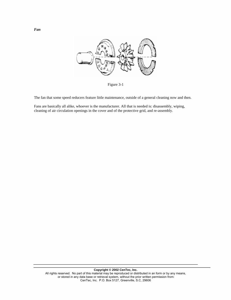
Fan
Figure 3-1
The fan that some speed reducers feature little maintenance, outside of a general cleaning now and then. Fans are basically all alike, whoever is the manufacturer. All that is needed is: disassembly, wiping, cleaning of air circulation openings in the cover and of the protective grid, and re-assembly.
Copyright © 2002 CenTec, Inc.
All rights reserved. No part of this material may be reproduced or distributed in an form or by any means, or stored in any data base or retrieval system, without the prior written permission from:
CenTec, Inc. P.O. Box 5127, Greenville, S.C, 29606

FASTENERS
Copyright © 2002 CenTec, Inc.
All rights reserved. No part of this material may be reproduced or distributed in an form or by any means, or stored in any data base or retrieval system, without the prior written permission from:
CenTec, Inc. P.O. Box 5127, Greenville, S.C, 29606
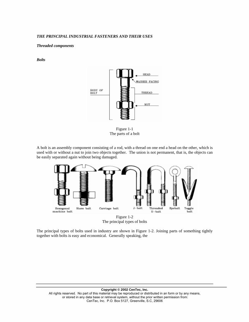
THE PRINCIPAL INDUSTRIAL FASTENERS AND THEIR USES Threaded components Bolts
Figure 1-1 The parts of a bolt
A bolt is an assembly component consisting of a rod, with a thread on one end a head on the other, which is used with or without a nut to join two objects together. The union is not permanent, that is, the objects can be easily separated again without being damaged.
Figure 1-2
The principal types of bolts
The principal types of bolts used in industry are shown in Figure 1-2. Joining parts of something tightly together with bolts is easy and economical. Generally speaking, the
Copyright © 2002 CenTec, Inc.
All rights reserved. No part of this material may be reproduced or distributed in an form or by any means, or stored in any data base or retrieval system, without the prior written permission from:
CenTec, Inc. P.O. Box 5127, Greenville, S.C, 29606
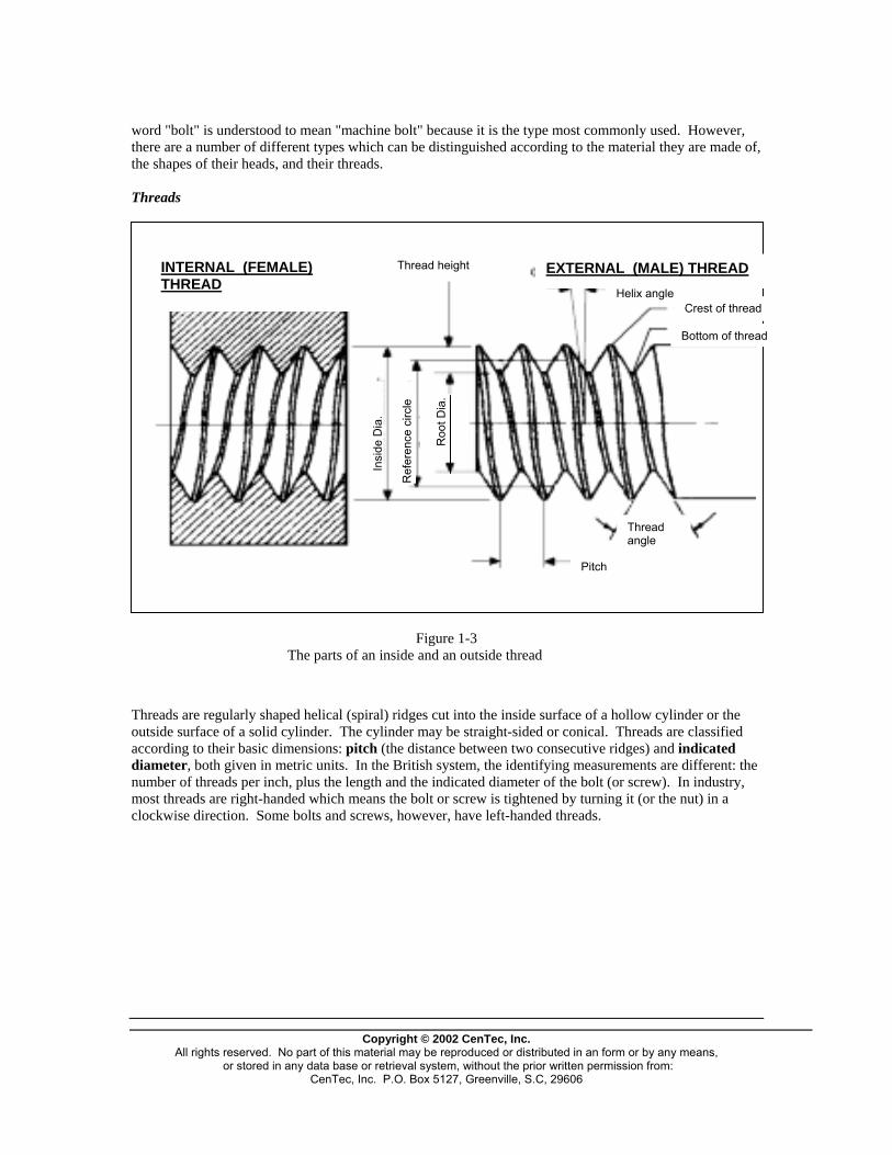
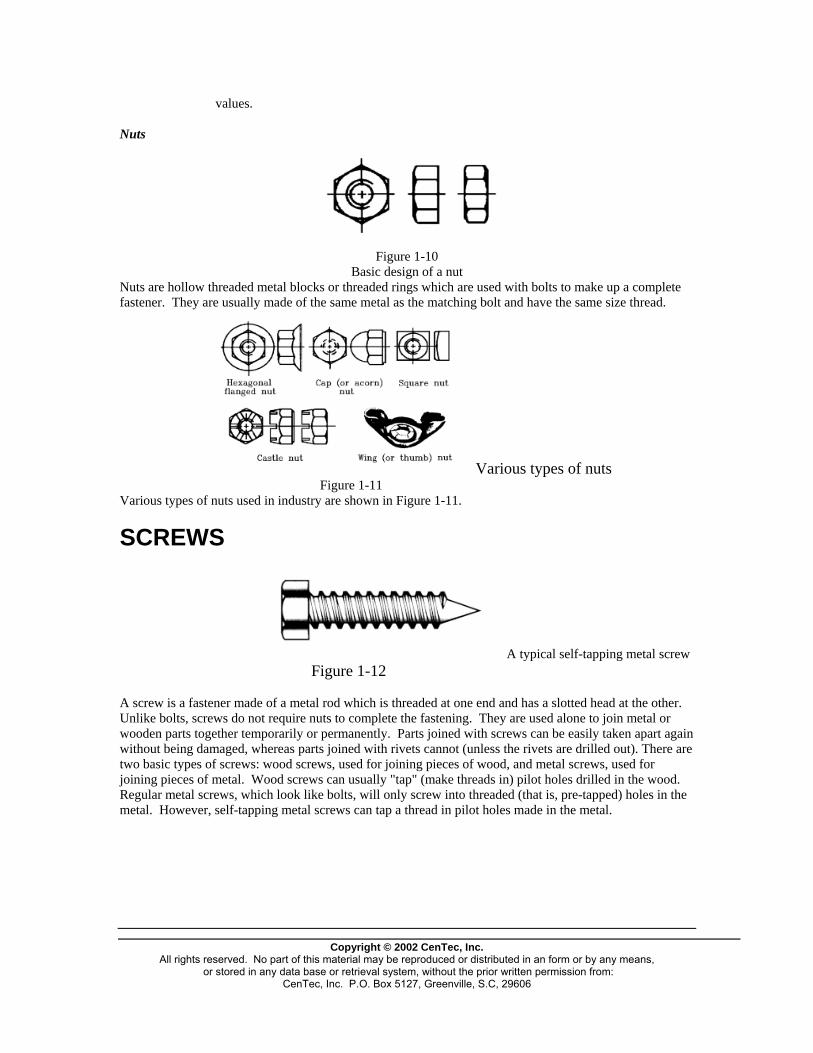
word "bolt" is understood to mean "machine bolt" because it is the type most commonly used. However, there are a number of different types which can be distinguished according to the material they are made of, the shapes of their heads, and their threads. Threads
Thread height
Roo
t Dia
.
Ref
eren
ce c
ircle
Insi
de D
ia.
Pitch
Thread angle
INTERNAL (FEMALE) THREAD
Crest of thread Helix angle
EXTERNAL (MALE) THREAD
Figure 1-3 The parts of an inside and an outside thread
Threads are regularly shaped helical (spiral) ridges cut into the inside surface of a hollow cyloutside surface of a solid cylinder. The cylinder may be straight-sided or conical. Threads aaccording to their basic dimensions: pitch (the distance between two consecutive ridges) anddiameter, both given in metric units. In the British system, the identifying measurements arnumber of threads per inch, plus the length and the indicated diameter of the bolt (or screw). most threads are right-handed which means the bolt or screw is tightened by turning it (or theclockwise direction. Some bolts and screws, however, have left-handed threads.
Copyright © 2002 CenTec, Inc.
All rights reserved. No part of this material may be reproduced or distributed in an form or by any or stored in any data base or retrieval system, without the prior written permission from:
CenTec, Inc. P.O. Box 5127, Greenville, S.C, 29606
Bottom of thread
inder or the re classified indicated e different: the In industry, nut) in a
means,

The various types of threads
0.6495D = 0.6495 X P or N
Figure 1-5
125 F = 0.125 X P or N
Figure 1-6
D = minimum 0.500P = maximum 0.500P + 0.010 F = 0.3707P C = 0.3707P – 0.0052 (for the greatest possible depth)
Figure 1-7
D = 0.500P W = 0.500p + 0.002
Figure 1-8
Figure 1-9 where: D = thread height (or depth) P = pitch N = number of threads per inch C = root width (the width of the flat part at the bottom oThe values of the outside (or major) diameter and the th
Copyright © 2002 CenTec, Inc.
All rights reserved. No part of this material may be reproduced or distribute or stored in any data base or retrieval system, without the prior wri
CenTec, Inc. P.O. Box 5127, Greenville, S.C, 29
D = 0.7035P(maximum) = 0.6855P (minimum)
f the thread). read angle are usually given
d in an form or by any means, tten permission from: 606
values. Nuts
Figure 1-10
Basic design of a nut Nuts are hollow threaded metal blocks or threaded rings which are used with bolts to make up a complete fastener. They are usually made of the same metal as the matching bolt and have the same size thread.
Various types of nuts Figure 1-11
Various types of nuts used in industry are shown in Figure 1-11.
SCREWS
A typical self-tapping metal screw Figure 1-12
A screw is a fastener made of a metal rod which is threaded at one end and has a slotted head at the other. Unlike bolts, screws do not require nuts to complete the fastening. They are used alone to join metal or wooden parts together temporarily or permanently. Parts joined with screws can be easily taken apart again without being damaged, whereas parts joined with rivets cannot (unless the rivets are drilled out). There are two basic types of screws: wood screws, used for joining pieces of wood, and metal screws, used for joining pieces of metal. Wood screws can usually "tap" (make threads in) pilot holes drilled in the wood. Regular metal screws, which look like bolts, will only screw into threaded (that is, pre-tapped) holes in the metal. However, self-tapping metal screws can tap a thread in pilot holes made in the metal.
Copyright © 2002 CenTec, Inc.
All rights reserved. No part of this material may be reproduced or distributed in an form or by any means, or stored in any data base or retrieval system, without the prior written permission from:
CenTec, Inc. P.O. Box 5127, Greenville, S.C, 29606
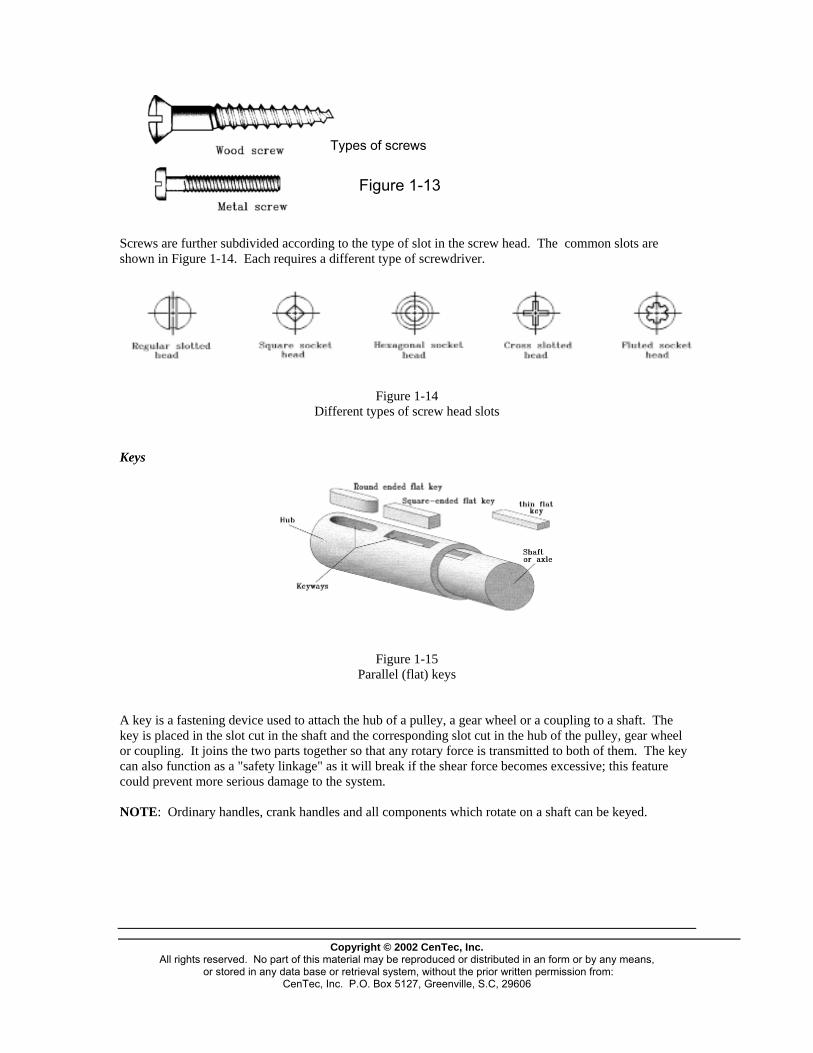
Types of screws
Figure 1-13
Screws are further subdivided according to the type of slot in the screw head. The common slots are shown in Figure 1-14. Each requires a different type of screwdriver.
Figure 1-14
Different types of screw head slots
Keys
Figure 1-15 Parallel (flat) keys
A key is a fastening device used to attach the hub of a pulley, a gear wheel or a coupling to a shaft. The key is placed in the slot cut in the shaft and the corresponding slot cut in the hub of the pulley, gear wheel or coupling. It joins the two parts together so that any rotary force is transmitted to both of them. The key can also function as a "safety linkage" as it will break if the shear force becomes excessive; this feature could prevent more serious damage to the system. NOTE: Ordinary handles, crank handles and all components which rotate on a shaft can be keyed.
Copyright © 2002 CenTec, Inc.
All rights reserved. No part of this material may be reproduced or distributed in an form or by any means, or stored in any data base or retrieval system, without the prior written permission from:
CenTec, Inc. P.O. Box 5127, Greenville, S.C, 29606
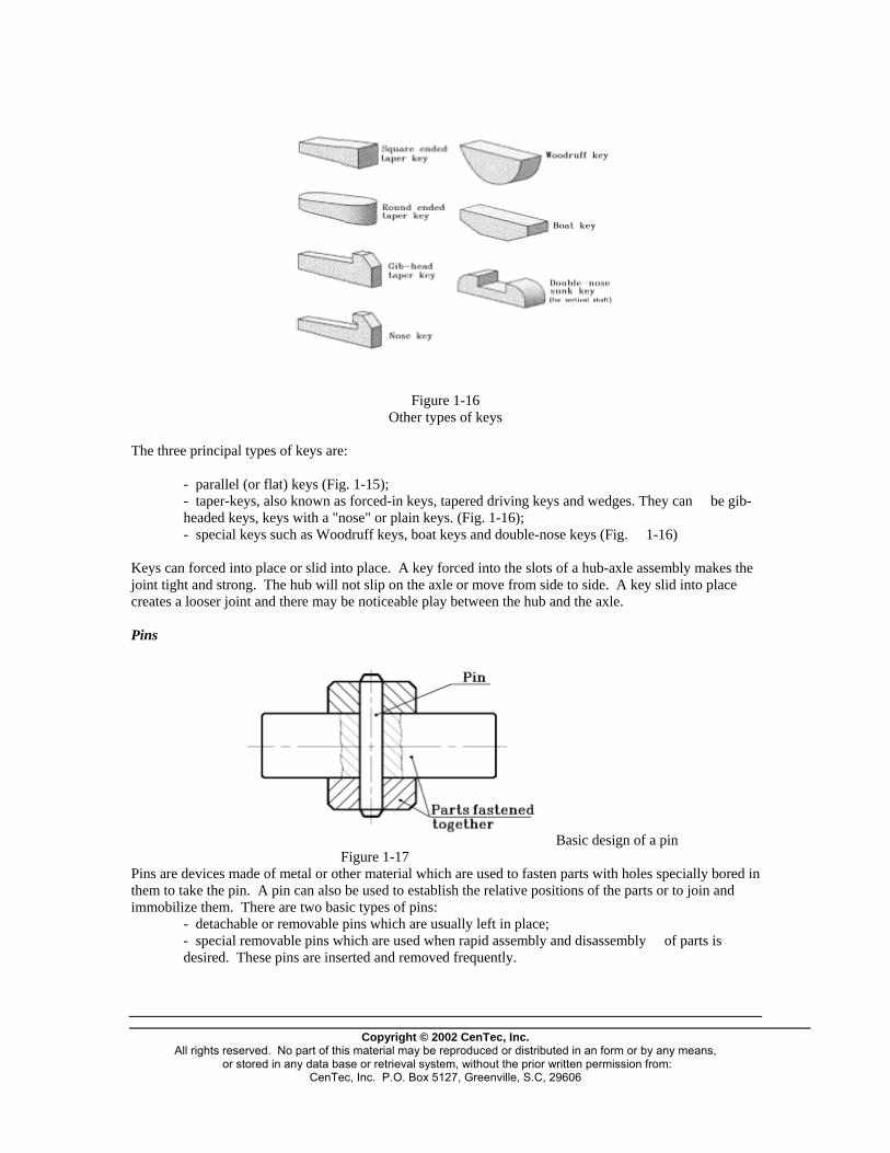
Figure 1-16 Other types of keys
The three principal types of keys are:
- parallel (or flat) keys (Fig. 1-15); - taper-keys, also known as forced-in keys, tapered driving keys and wedges. They can be gib-headed keys, keys with a "nose" or plain keys. (Fig. 1-16); - special keys such as Woodruff keys, boat keys and double-nose keys (Fig. 1-16)
Keys can forced into place or slid into place. A key forced into the slots of a hub-axle assembly makes the joint tight and strong. The hub will not slip on the axle or move from side to side. A key slid into place creates a looser joint and there may be noticeable play between the hub and the axle. Pins
Basic design of a pin Figure 1-17
Pins are devices made of metal or other material which are used to fasten parts with holes specially bored in them to take the pin. A pin can also be used to establish the relative positions of the parts or to join and immobilize them. There are two basic types of pins:
- detachable or removable pins which are usually left in place; - special removable pins which are used when rapid assembly and disassembly of parts is desired. These pins are inserted and removed frequently.
Copyright © 2002 CenTec, Inc.
All rights reserved. No part of this material may be reproduced or distributed in an form or by any means, or stored in any data base or retrieval system, without the prior written permission from:
CenTec, Inc. P.O. Box 5127, Greenville, S.C, 29606
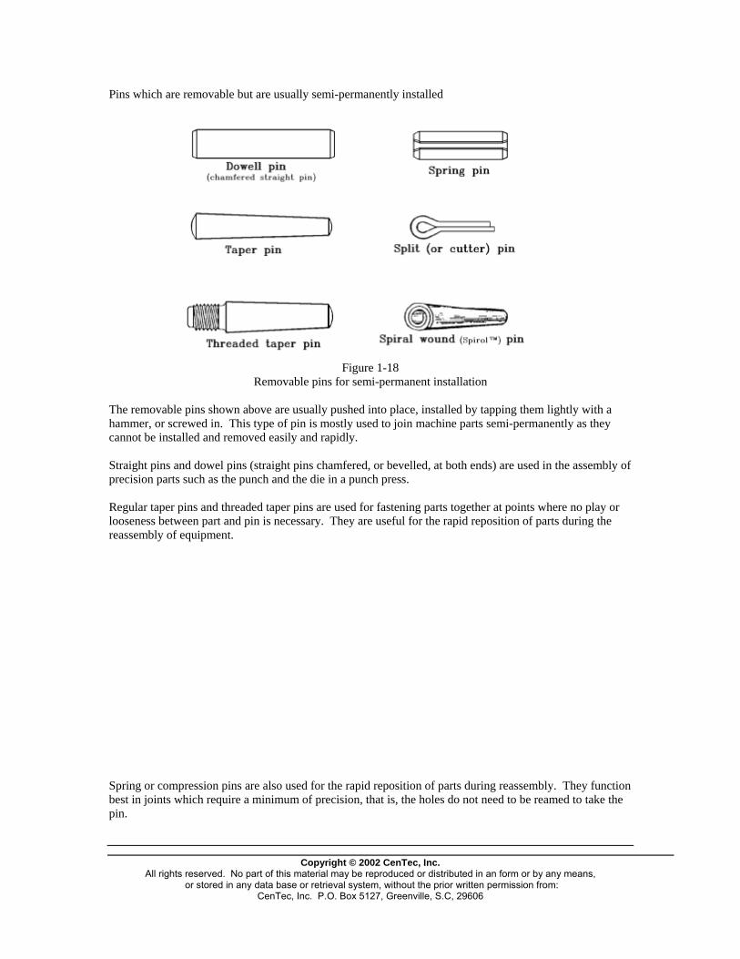
Pins which are removable but are usually semi-permanently installed
Figure 1-18
Removable pins for semi-permanent installation
The removable pins shown above are usually pushed into place, installed by tapping them lightly with a hammer, or screwed in. This type of pin is mostly used to join machine parts semi-permanently as they cannot be installed and removed easily and rapidly. Straight pins and dowel pins (straight pins chamfered, or bevelled, at both ends) are used in the assembly of precision parts such as the punch and the die in a punch press. Regular taper pins and threaded taper pins are used for fastening parts together at points where no play or looseness between part and pin is necessary. They are useful for the rapid reposition of parts during the reassembly of equipment. Spring or compression pins are also used for the rapid reposition of parts during reassembly. They function best in joints which require a minimum of precision, that is, the holes do not need to be reamed to take the pin.
Copyright © 2002 CenTec, Inc.
All rights reserved. No part of this material may be reproduced or distributed in an form or by any means, or stored in any data base or retrieval system, without the prior written permission from:
CenTec, Inc. P.O. Box 5127, Greenville, S.C, 29606
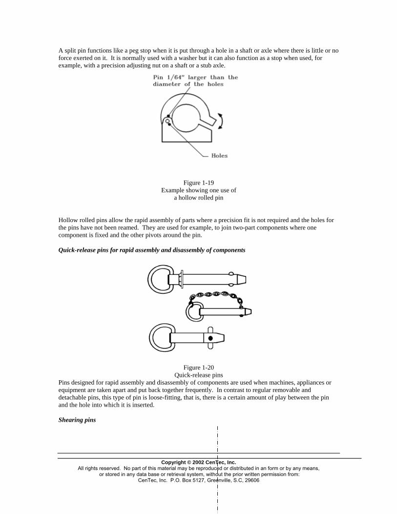
A split pin functions like a peg stop when it is put through a hole in a shaft or axle where there is little or no force exerted on it. It is normally used with a washer but it can also function as a stop when used, for example, with a precision adjusting nut on a shaft or a stub axle.
Figure 1-19 Example showing one use of
a hollow rolled pin
Hollow rolled pins allow the rapid assembly of parts where a precision fit is not required and the holes for the pins have not been reamed. They are used for example, to join two-part components where one component is fixed and the other pivots around the pin. Quick-release pins for rapid assembly and disassembly of components
Figure 1-20 Quick-release pins
Pins designed for rapid assembly and disassembly of components are used when machines, appliances or equipment are taken apart and put back together frequently. In contrast to regular removable and detachable pins, this type of pin is loose-fitting, that is, there is a certain amount of play between the pin and the hole into which it is inserted. Shearing pins
Copyright © 2002 Cen ec, Inc.
All rights reserved. No part of this material may be reproduced or distributed in an form or by any means, or stored in any data base or retrieval system, without the prior written permission from:
CenTec, Inc. P.O. Box 5127, Greenville, S.C, 29606
T
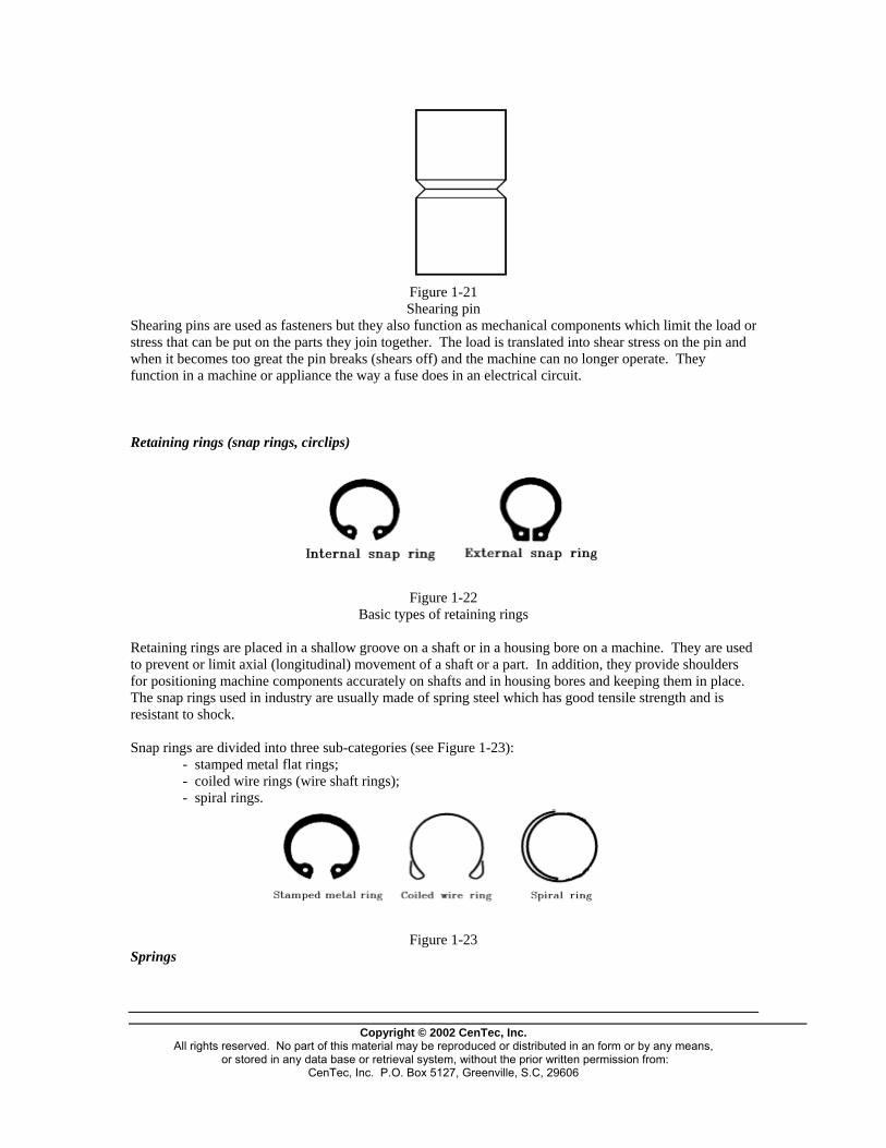
Figure 1-21 Shearing pin
Shearing pins are used as fasteners but they also function as mechanical components which limit the load or stress that can be put on the parts they join together. The load is translated into shear stress on the pin and when it becomes too great the pin breaks (shears off) and the machine can no longer operate. They function in a machine or appliance the way a fuse does in an electrical circuit. Retaining rings (snap rings, circlips)
Figure 1-22
Basic types of retaining rings
Retaining rings are placed in a shallow groove on a shaft or in a housing bore on a machine. They are used to prevent or limit axial (longitudinal) movement of a shaft or a part. In addition, they provide shoulders for positioning machine components accurately on shafts and in housing bores and keeping them in place. The snap rings used in industry are usually made of spring steel which has good tensile strength and is resistant to shock. Snap rings are divided into three sub-categories (see Figure 1-23):
- stamped metal flat rings; - coiled wire rings (wire shaft rings); - spiral rings.
Figure 1-23
Springs
Copyright © 2002 CenTec, Inc.
All rights reserved. No part of this material may be reproduced or distributed in an form or by any means, or stored in any data base or retrieval system, without the prior written permission from:
CenTec, Inc. P.O. Box 5127, Greenville, S.C, 29606
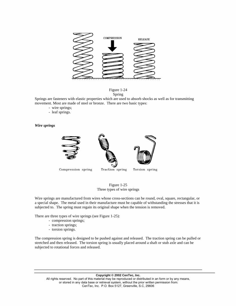
Figure 1-24
Spring Springs are fasteners with elastic properties which are used to absorb shocks as well as for transmitting movement. Most are made of steel or bronze. There are two basic types:
- wire springs; - leaf springs.
Wire springs
Figure 1-25 Three types of wire springs
Wire springs are manufactured from wires whose cross-sections can be round, oval, square, rectangular, or a special shape. The metal used in their manufacture must be capable of withstanding the stresses that it is subjected to. The spring must regain its original shape when the tension is removed. There are three types of wire springs (see Figure 1-25):
- compression springs; - traction springs; - torsion springs.
The compression spring is designed to be pushed against and released. The traction spring can be pulled or stretched and then released. The torsion spring is usually placed around a shaft or stub axle and can be subjected to rotational forces and released.
Copyright © 2002 CenTec, Inc.
All rights reserved. No part of this material may be reproduced or distributed in an form or by any means, or stored in any data base or retrieval system, without the prior written permission from:
CenTec, Inc. P.O. Box 5127, Greenville, S.C, 29606

Leaf springs
Figure 1-26 Leaf spring
Leaf springs are made up of one or more narrow metal bands and are designed to withstand bending stress. The metal must have elastic properties. The following metals and alloys have these properties when tempered under carefully controlled conditions: steel, stainless steel, bronze, copper, brass, and nickel. Metals and alloys used in the manufacture of springs The carbon steel wires most often used in the manufacture of springs are those which meet the standards:
- ASTM A228 (piano wire) for round wires 0.005 — 0.125" in diameter. - ASTM A229 (tempered in oil) for round wires 0.125 — 0.5" in
diameter. The carbon steel flat tongues or wires most often used in the manufacture of flat wire springs are those which meet the standards:
- SAE 1074 (tempered) for wires 0.005 — 0.062" thick. - SAE 1095 (tempered) for springs used in motors.
Steel alloy standards - ASTM A231 (chromium-vanadium steel) for wires 0.031 — 0.500" in
diameter, and for springs with good resistance to metal fatigue. Various types of stainless steel, copper-based alloys and nickel-based alloys are also used to make springs. Example: copper meeting the standards ASTM B134, ASTM B195 and ASTM
B197. stainless steel meeting the standards ASTM A313 and SAE 51431 nickel alloys called Elinvar and Dynavar.
NOTE: For other metals and alloys please refer to Machinery Handbook.
Copyright © 2002 CenTec, Inc.
All rights reserved. No part of this material may be reproduced or distributed in an form or by any means, or stored in any data base or retrieval system, without the prior written permission from:
CenTec, Inc. P.O. Box 5127, Greenville, S.C, 29606

Rivets
Figure 1-27 Solid rivet
Rivets are fasteners which are used to make low-cost, reliable joints. They can be used to join pieces of metal, leather, cloth and plastic. They are usually made of ductile metals like steel, aluminum, copper or brass. In general, a rivet consists of two parts: a hollow (tubular) body, split body or solid body (or shank) which is inserted in the holes drilled in the two parts, and a head, which is pushed against one of the pieces being joined. The joint is made when the free end of the body is hammered to form a "second head" or is clinched (bent, flattened or expanded) so that it is pushed against the second piece in the joint. Once installed, rivets create a permanent joint and cannot be recovered for reuse. In other words, the pieces cannot be separated unless the rivets are destroyed or rendered useless by filing or drilling.
Figure 1-28 Types of rivets
Ordinary rivets are classified according to body type and the shape of their heads.
Copyright © 2002 CenTec, Inc.
All rights reserved. No part of this material may be reproduced or distributed in an form or by any means, or stored in any data base or retrieval system, without the prior written permission from:
CenTec, Inc. P.O. Box 5127, Greenville, S.C, 29606

Washers
Figure 1-29 A typical metal washer
Washers are fastening accessories which are widely used in industry. Most are made of metal. Depending on their diameters and shapes, they can be used to increase the effective surface area of the part of the bolt head or the nut resting against the part, or to stop the bolt or nut from working loose. Non-metallic washers are used as insulators in certain kinds of electrical equipment and as thermal barriers between metallic parts. In other equipment, washers made of soft or elastic material are used to make joints watertight.
Figure 1-30 The principal types of washers
The principal types of washers used in industry are shown in Figure 1-30. The square plate washer increases the surface area of the part of the fastener in contact with the component, the lock washer with overlapping teeth, the double spiral spring washer, and the Grower lock washer are used to lock screws, bolts or nuts in place, and the Belleville sealing washer is used in watertight or gas-tight joints. NOTE: The double spiral spring washer allows the joint to absorb a certain amount of vibration without losing its effectiveness.
Copyright © 2002 CenTec, Inc.
All rights reserved. No part of this material may be reproduced or distributed in an form or by any means, or stored in any data base or retrieval system, without the prior written permission from:
CenTec, Inc. P.O. Box 5127, Greenville, S.C, 29606
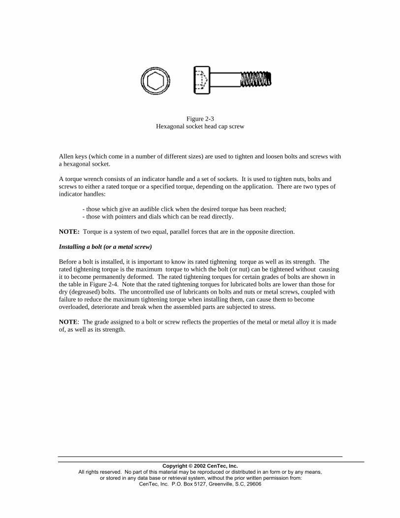
Figure 2-3 Hexagonal socket head cap screw
Allen keys (which come in a number of different sizes) are used to tighten and loosen bolts and screws with a hexagonal socket. A torque wrench consists of an indicator handle and a set of sockets. It is used to tighten nuts, bolts and screws to either a rated torque or a specified torque, depending on the application. There are two types of indicator handles:
- those which give an audible click when the desired torque has been reached; - those with pointers and dials which can be read directly.
NOTE: Torque is a system of two equal, parallel forces that are in the opposite direction. Installing a bolt (or a metal screw) Before a bolt is installed, it is important to know its rated tightening torque as well as its strength. The rated tightening torque is the maximum torque to which the bolt (or nut) can be tightened without causing it to become permanently deformed. The rated tightening torques for certain grades of bolts are shown in the table in Figure 2-4. Note that the rated tightening torques for lubricated bolts are lower than those for dry (degreased) bolts. The uncontrolled use of lubricants on bolts and nuts or metal screws, coupled with failure to reduce the maximum tightening torque when installing them, can cause them to become overloaded, deteriorate and break when the assembled parts are subjected to stress. NOTE: The grade assigned to a bolt or screw reflects the properties of the metal or metal alloy it is made of, as well as its strength.
Copyright © 2002 CenTec, Inc.
All rights reserved. No part of this material may be reproduced or distributed in an form or by any means, or stored in any data base or retrieval system, without the prior written permission from:
CenTec, Inc. P.O. Box 5127, Greenville, S.C, 29606
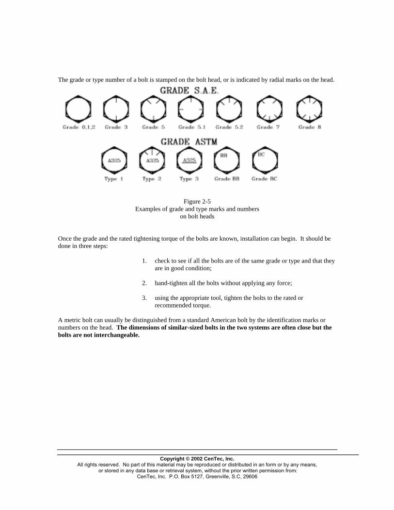
The grade or type number of a bolt is stamped on the bolt head, or is indicated by radial marks on the head.
Figure 2-5
Examples of grade and type marks and numbers on bolt heads
Once the grade and the rated tightening torque of the bolts are known, installation can begin. It should be done in three steps: 1. check to see if all the bolts are of the same grade or type and that they
are in good condition; 2. hand-tighten all the bolts without applying any force; 3. using the appropriate tool, tighten the bolts to the rated or
recommended torque. A metric bolt can usually be distinguished from a standard American bolt by the identification marks or numbers on the head. The dimensions of similar-sized bolts in the two systems are often close but the bolts are not interchangeable.
Copyright © 2002 CenTec, Inc.
All rights reserved. No part of this material may be reproduced or distributed in an form or by any means, or stored in any data base or retrieval system, without the prior written permission from:
CenTec, Inc. P.O. Box 5127, Greenville, S.C, 29606

Figure 2-6 Sequence for a ring-shaped joint
When an assembly requires several bolts, the type of tightening sequence shown in Figure 2-6 should be followed to make sure the parts will not warp or buckle. NOTE: The nuts or bolts should be finger-tightened at first and then tightened in stages with the appropriate tool. The same tightening sequence should be followed during each stage. If a bolt in a joint made with a gasket or sealing washer is tightened to the rated or recommended torque, the torque measured 24 hours after the installation may be up to 25% less than the initial value. When a torque is applied to a bolt as it is tightened, most of the applied force is transformed into pressure on the gasket or sealing washer; the rest is used to overcome the friction between the threads. Gaskets or sealing washers are usually composed of material which can undergo slight deformation when highly compressed. During the 24 hours after the initial tightening of the bolts the gaskets or washers pack down and do not exert the same force on the bolt as before. This is why it is always a good idea to tighten nuts and bolts used in this type of joint again a day or so after they have been installed.
Copyright © 2002 CenTec, Inc.
All rights reserved. No part of this material may be reproduced or distributed in an form or by any means, or stored in any data base or retrieval system, without the prior written permission from:
CenTec, Inc. P.O. Box 5127, Greenville, S.C, 29606

Copyright © 2002 CenTec, Inc.
All rights reserved. No part of this material may be reproduced or distributed in an form or by any means, or stored in any data base or retrieval system, without the prior written permission from:
CenTec, Inc. P.O. Box 5127, Greenville, S.C, 29606
Problems and solutions
PROBLEM SYMPTOMS POSSIBLE CAUSES SOLUTIONS OVERSTRETCHED BOLT OR SCREW
Bolts continually need tightening. Periodic equipment break-down caused by slight misalignment of parts.
- torque too high for the class of bolts or screws used - the load on the bolt or screw is greater than its elastic limit
- adjust the torque to the correct value for the class of bolt or screw - use sturdier bolts or screws, i.e., bolts or screws in the appropriate class
RUPTURE CAUSED BY FATIGUE
Sudden breakage of parts subjected to vibration or to loads which are slightly higher than usual.
- rated tightening torque is too low - loss of initial rated tightening torque because of: - indentations made in the joined parts by the bolt, screw or nut - stretching of the bolt or screw - loosening of the bolt or screw - incorrect use of lubricants - metal shavings or dirt under the bolt head, the head of the metal screw, under the nut, or between the joined parts - the shifting of parts - an incorrect tightening sequence, if several bolts or metal screws are used in the joint - the bending of parts when the joint is tightened - a bolt, screw or nut having been subjected to a high temperature
- use a stronger bolt or screw with a greater tightening torque - put a flat tempered steel washer under the head of the bolt or screw and under the nut (if there is one) - choose a sturdier screw or bolt from a higher class - check the torque, adjust if necessary; consider the use of lock-nuts or lock-washers - try tightening the joint without lubricant, or cautiously increase the tightening torque - clean all joint surfaces - cautiously increase the tightening torque or choose a sturdier bolt from a higher class - check the tightening order recommended by the manufacturer and make sure all bolts or screws share the load on the joint equally - check to see if the parts (including gaskets) are deformed; if they are, try using a lower tightening torque - choose a bolt or screw designed for use at high temperatures
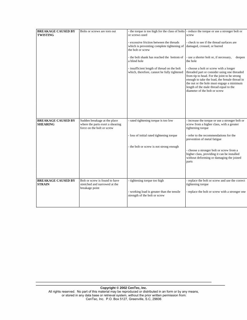
Copyright © 2002 CenTec, Inc.
All rights reserved. No part of this material may be reproduced or distributed in an form or by any means, or stored in any data base or retrieval system, without the prior written permission from:
CenTec, Inc. P.O. Box 5127, Greenville, S.C, 29606
BREAKAGE CAUSED BY TWISTING
Bolts or screws are torn out - the torque is too high for the class of bolts or screws used - excessive friction between the threads which is preventing complete tightening of the bolt or screw - the bolt shank has reached the bottom of a blind hole - insufficient length of thread on the bolt which, therefore, cannot be fully tightened
- reduce the torque or use a stronger bolt or screw - check to see if the thread surfaces are damaged, crossed, or burred - use a shorter bolt or, if necessary, deepen the hole - choose a bolt or screw with a longer threaded part or consider using one threaded from tip to head. For the joint to be strong enough to take the load, the female thread in the nut or the hole must engage a minimum length of the male thread equal to the diameter of the bolt or screw
BREAKAGE CAUSED BY SHEARING
Sudden breakage at the place where the parts exert a shearing force on the bolt or screw
- rated tightening torque is too low - loss of initial rated tightening torque - the bolt or screw is not strong enough
- increase the torque or use a stronger bolt or screw from a higher class, with a greater tightening torque - refer to the recommendations for the prevention of metal fatigue - choose a stronger bolt or screw from a higher class, providing it can be installed without deforming or damaging the joined parts
BREAKAGE CAUSED BY STRAIN
Bolt or screw is found to have stretched and narrowed at the breakage point
- tightening torque too high - working load is greater than the tensile strength of the bolt or screw
- replace the bolt or screw and use the correct tightening torque - replace the bolt or screw with a stronger one

Copyright © 2002 CenTec, Inc.
All rights reserved. No part of this material may be reproduced or distributed in an form or by any means, or stored in any data base or retrieval system, without the prior written permission from:
CenTec, Inc. P.O. Box 5127, Greenville, S.C, 29606
CHRONIC LOOSENING
Bolts or nuts frequently need to be tightened
- working load is greater than the tensile strength of the bolt or screw and the bolt or screw is gradually stretching - tightening torque is too low - indentations made in the joined parts by the bolt, screw or nut - metal shavings or dirt under the bolt head, the head of the metal screw, under the nut, or between the joined parts - incorrect use of lubricants - the shifting of parts - an incorrect tightening sequence, if several bolts or metal screws are used in the joint - the parts in the joint might have been deformed or bent when the bolt or screw was tightened - the bolt, screw or nut has been subjected to a high temperature and has been permanently stretched
- use a stronger bolt or screw (from a higher class) - adjust the torque so that it is equal to the torque recommended for the bolt or screw - put a flat tempered steel washer under the head of the bolt or screw and under the nut (if there is one) - clean all joint surfaces - try tightening the joint without lubricant, or cautiously increase the tightening torque - cautiously increase the tightening torque or choose a sturdier bolt from a higher class - check the tightening order recommended by the manufacturer and make sure all bolts or screws share the load on the joint equally - check to see if the parts (including gaskets) are deformed; if they are, try using a lower tightening torque - choose a bolt or screw designed for use at high temperatures
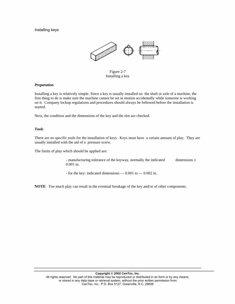
Installing keys
Figure 2-7
Installing a key Preparation Installing a key is relatively simple. Since a key is usually installed on the shaft or axle of a machine, the first thing to do is make sure the machine cannot be set in motion accidentally while someone is working on it. Company lockup regulations and procedures should always be followed before the installation is started. Next, the condition and the dimensions of the key and the slot are checked. Tools There are no specific tools for the installation of keys. Keys must have a certain amount of play. They are usually installed with the aid of a pressure screw. The limits of play which should be applied are:
- manufacturing tolerance of the keyway, normally the indicated dimensions ± 0.001 in.
- for the key: indicated dimensions — 0.001 to — 0.002 in.
NOTE: Too much play can result in the eventual breakage of the key and/or of other components.
Copyright © 2002 CenTec, Inc.
All rights reserved. No part of this material may be reproduced or distributed in an form or by any means, or stored in any data base or retrieval system, without the prior written permission from:
CenTec, Inc. P.O. Box 5127, Greenville, S.C, 29606

Installing a key
Figure 2-8 Typical keyed hub-and-shaft assemblies
To install a key, place the hub of the part (for example, a gear wheel or a pulley) squarely on the shaft and push the key in manually. It might be necessary to tap the key very lightly with a hammer to get it in the right place. Tighten the pressure screw to push the key into its final position. When installing a Woodruff key, place it in the shaft first before sliding the hub (of the gear wheel or pulley) into place on the shaft. Then push the key into its final position with the pressure screw.
Figure 2-9
Determining the position of the key
When the part of the groove on the shaft outside the hub of the gear wheel or pulley is long, choose a key long enough to fill half this length so as to avoid creating an assembly which is excessively out of balance.
Copyright © 2002 CenTec, Inc.
All rights reserved. No part of this material may be reproduced or distributed in an form or by any means, or stored in any data base or retrieval system, without the prior written permission from:
CenTec, Inc. P.O. Box 5127, Greenville, S.C, 29606

When the part (hub, gear-wheel etc.) and the shaft are made out of different materials, the value for the length of key required must be modified using the following calculation:
of key required Length )2
( 2
112
2
11
PPxLL
PPxL
−
+=
P1 = specific gravity of the part P2 = specific gravity of the shaft
Example: The part is made of aluminum The shaft is made of steel
L1 = 6 inches L2 = 10 inches
The specific gravity of aluminum is approximately one-third that of steel.
31
2
1 =PP
Length of key required = )2
31610
(316
xx
−+
42 += 6 ′′=
The length of key required in this example is 6 inches, whereas it would have been 8 inches if the part had been made of the same kind of steel as the shaft.
Copyright © 2002 CenTec, Inc.
All rights reserved. No part of this material may be reproduced or distributed in an form or by any means, or stored in any data base or retrieval system, without the prior written permission from:
CenTec, Inc. P.O. Box 5127, Greenville, S.C, 29606

Installing pins
Figure 2-10
Straight pin Taper pin
(pin shown is a dowel pin) Straight pins and taper pins No special tools or elaborate methods are required for the installation of a straight pin or a taper pin. It is sufficient to make sure the pin is not cracked or warped and that the holes in the parts to be joined are properly aligned. The pin must be at least twice as long as its diameter. The holes for the pin are first bored to a diameter slightly smaller than that of the pin, then reamed to the diameter required for a precision fit. NOTE: Holes for pins should not be completely blind. In joints where the hole does not go all the way through, a small hole should be drilled in the blind end so that a rod can be inserted to knock the pin out when required. Taper pins should be checked to make sure they are the right size and that they have the correct taper so that will seat properly in the hole.
Copyright © 2002 CenTec, Inc.
All rights reserved. No part of this material may be reproduced or distributed in an form or by any means, or stored in any data base or retrieval system, without the prior written permission from:
CenTec, Inc. P.O. Box 5127, Greenville, S.C, 29606
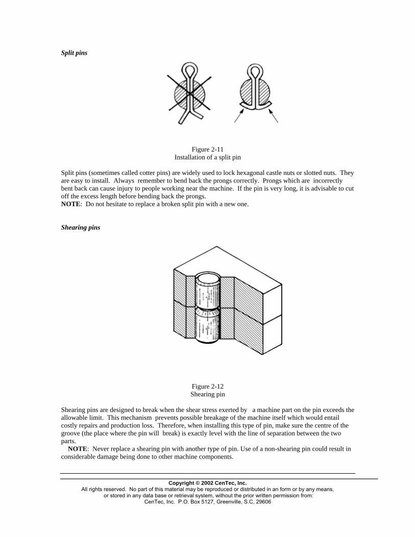
Split pins
Figure 2-11 Installation of a split pin
Split pins (sometimes called cotter pins) are widely used to lock hexagonal castle nuts or slotted nuts. They are easy to install. Always remember to bend back the prongs correctly. Prongs which are incorrectly bent back can cause injury to people working near the machine. If the pin is very long, it is advisable to cut off the excess length before bending back the prongs. NOTE: Do not hesitate to replace a broken split pin with a new one. Shearing pins
Figure 2-12 Shearing pin
Shearing pins are designed to break when the shear stress exerted by a machine part on the pin exceeds the allowable limit. This mechanism prevents possible breakage of the machine itself which would entail costly repairs and production loss. Therefore, when installing this type of pin, make sure the centre of the groove (the place where the pin will break) is exactly level with the line of separation between the two parts. NOTE: Never replace a shearing pin with another type of pin. Use of a non-shearing pin could result in considerable damage being done to other machine components.
Copyright © 2002 CenTec, Inc.
All rights reserved. No part of this material may be reproduced or distributed in an form or by any means, or stored in any data base or retrieval system, without the prior written permission from:
CenTec, Inc. P.O. Box 5127, Greenville, S.C, 29606
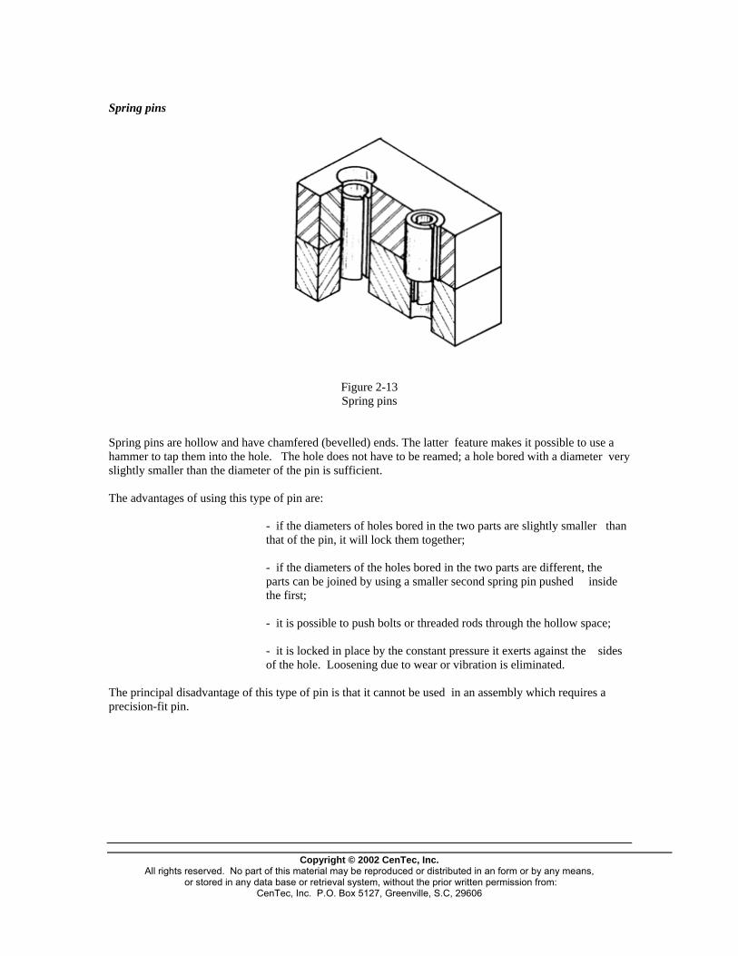
Spring pins
Figure 2-13 Spring pins
Spring pins are hollow and have chamfered (bevelled) ends. The latter feature makes it possible to use a hammer to tap them into the hole. The hole does not have to be reamed; a hole bored with a diameter very slightly smaller than the diameter of the pin is sufficient. The advantages of using this type of pin are:
- if the diameters of holes bored in the two parts are slightly smaller than that of the pin, it will lock them together;
- if the diameters of the holes bored in the two parts are different, the parts can be joined by using a smaller second spring pin pushed inside the first;
- it is possible to push bolts or threaded rods through the hollow space;
- it is locked in place by the constant pressure it exerts against the sides of the hole. Loosening due to wear or vibration is eliminated.
The principal disadvantage of this type of pin is that it cannot be used in an assembly which requires a precision-fit pin.
Copyright © 2002 CenTec, Inc.
All rights reserved. No part of this material may be reproduced or distributed in an form or by any means, or stored in any data base or retrieval system, without the prior written permission from:
CenTec, Inc. P.O. Box 5127, Greenville, S.C, 29606
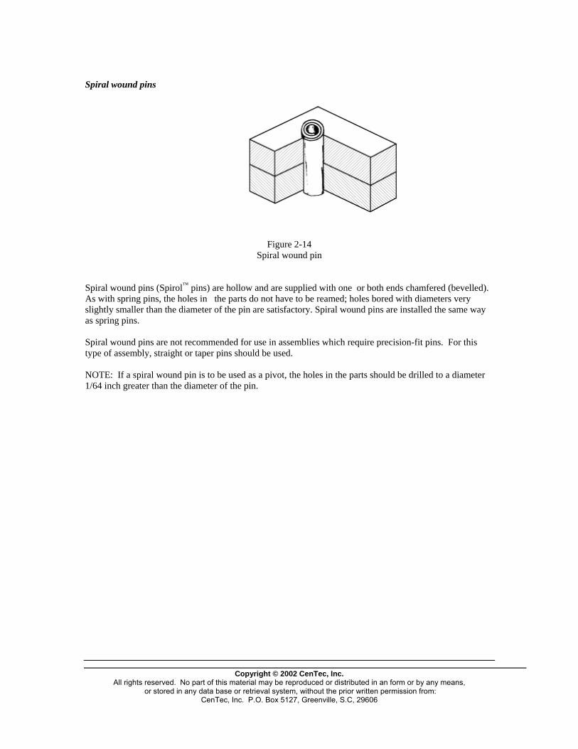
Spiral wound pins
Figure 2-14 Spiral wound pin
Spiral wound pins (Spirol™ pins) are hollow and are supplied with one or both ends chamfered (bevelled). As with spring pins, the holes in the parts do not have to be reamed; holes bored with diameters very slightly smaller than the diameter of the pin are satisfactory. Spiral wound pins are installed the same way as spring pins. Spiral wound pins are not recommended for use in assemblies which require precision-fit pins. For this type of assembly, straight or taper pins should be used. NOTE: If a spiral wound pin is to be used as a pivot, the holes in the parts should be drilled to a diameter 1/64 inch greater than the diameter of the pin.
Copyright © 2002 CenTec, Inc.
All rights reserved. No part of this material may be reproduced or distributed in an form or by any means, or stored in any data base or retrieval system, without the prior written permission from:
CenTec, Inc. P.O. Box 5127, Greenville, S.C, 29606
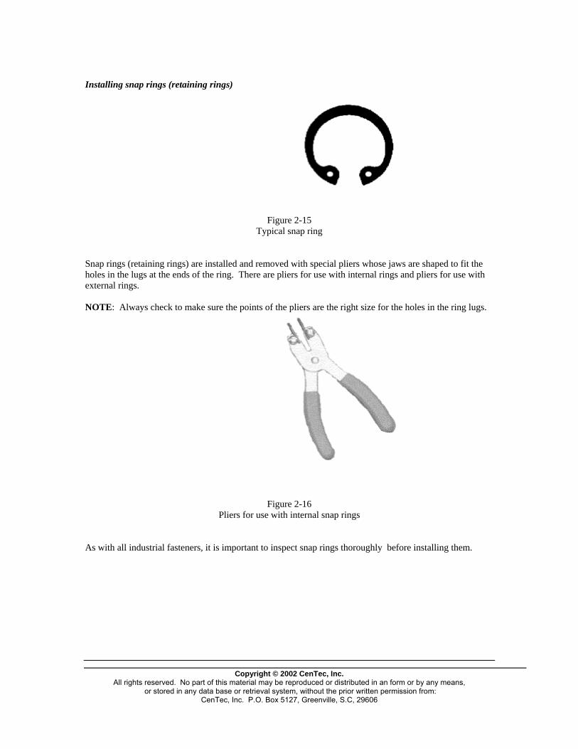
Installing snap rings (retaining rings)
Figure 2-15 Typical snap ring
Snap rings (retaining rings) are installed and removed with special pliers whose jaws are shaped to fit the holes in the lugs at the ends of the ring. There are pliers for use with internal rings and pliers for use with external rings. NOTE: Always check to make sure the points of the pliers are the right size for the holes in the ring lugs.
Figure 2-16
Pliers for use with internal snap rings As with all industrial fasteners, it is important to inspect snap rings thoroughly before installing them.
Copyright © 2002 CenTec, Inc.
All rights reserved. No part of this material may be reproduced or distributed in an form or by any means, or stored in any data base or retrieval system, without the prior written permission from:
CenTec, Inc. P.O. Box 5127, Greenville, S.C, 29606

Installing springs Springs are installed in two ways: with anchoring and without anchoring. Preparation Before beginning the installation of a spring, the worker should make sure that it is the right type for the job, that the dimensions correspond to those specified, and that it is in good condition (it is not rusted, cracked or deformed). Installation with anchoring
Figure 2-17 Installation with anchoring
When a spring is installed with anchoring, the ends are placed in holes or slots specially made for the purpose. Sometimes, to lock certain types of springs in place, the ends have to be bent back on themselves with pliers to form hooks or loops. Installation without anchoring
Figure 2-18 Installation without anchoring
A spring installed without anchoring is usually inserted in a housing or slipped over an axle or a rod. It must not rub excessively against the surface of the housing or the rod because its efficiency will be reduced and it might eventually jam or bind. Thus, the worker should always make sure the spring is the right size for the job.
Copyright © 2002 CenTec, Inc.
All rights reserved. No part of this material may be reproduced or distributed in an form or by any means, or stored in any data base or retrieval system, without the prior written permission from:
CenTec, Inc. P.O. Box 5127, Greenville, S.C, 29606
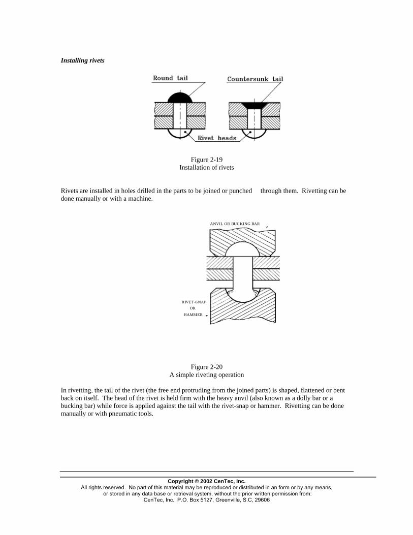
Installing rivets
Figure 2-19
Installation of rivets
Rivets are installed in holes drilled in the parts to be joined or punched through them. Rivetting can be done manually or with a machine.
ANVIL OR BUCKING BAR
RIVET -SNAPOR
HAMMER
Figure 2-20 A simple riveting operation
In rivetting, the tail of the rivet (the free end protruding from the joined parts) is shaped, flattened or bent back on itself. The head of the rivet is held firm with the heavy anvil (also known as a dolly bar or a bucking bar) while force is applied against the tail with the rivet-snap or hammer. Rivetting can be done manually or with pneumatic tools.
Copyright © 2002 CenTec, Inc.
All rights reserved. No part of this material may be reproduced or distributed in an form or by any means, or stored in any data base or retrieval system, without the prior written permission from:
CenTec, Inc. P.O. Box 5127, Greenville, S.C, 29606

Pull-through blind rivets
Figure 2-21 Installation of a pull-through blind rivet
A pull-through blind rivet has a head and a tubular body inside of which is a long rod or pull stem which protrudes from both ends. One end of the stem has a slightly enlarged head or spur. After the rivet has been pushed through the joint holes, a special tool is used to pull on the stem while keeping the rivet in place. As the rod is pulled, the head or spur pushes against the end of the hollow rivet causing it to deform and expand tightly in the joint hole and against the undersurface of the joint. The end of the stem is now locked in place and the continued traction on the stem breaks it off inside the body of the rivet, near the spur. NOTE: It is important to choose a rivet with the proper body length, so that when the stem is pulled, the spur will expand the end of the rivet tightly against the undersurface of the joint. Installing washers
Figure 2-22
A washer installed under the head of a bolt
The installation of washers is very simple: simply put the washer on the bolt or the threaded rod and tighten the bolt or the nut. However, lock-washers must be installed according to the design. For example, a Grower spring lock washer has a left-handed spiral which makes tightening the metal screw or nut easier. The end of the spiral becomes slightly embedded in the surfaces of the part and the screw head or nut, thus preventing the latter from loosening. NOTE: Lock washers lose much of their effectiveness once they have been used in a joint. When lock washers are removed, they should not be used again.
Copyright © 2002 CenTec, Inc.
All rights reserved. No part of this material may be reproduced or distributed in an form or by any means, or stored in any data base or retrieval system, without the prior written permission from:
CenTec, Inc. P.O. Box 5127, Greenville, S.C, 29606

Copyright © 2002 CenTec, Inc.
All rights reserved. No part of this material may be reproduced or distributed in an form or by any means, or stored in any data base or retrieval system, without the prior written permission from:
CenTec, Inc. P.O. Box 5127, Greenville, S.C, 29606

Copyright © 2002 CenTec, Inc. All rights reserved. No part of this material may be reproduced or distributed in an form or by any means,
or stored in any data base or retrieval system, without the prior written permission from: CenTec, Inc. P.O. Box 5127, Greenville, S.C, 29606

LUBRICATION
Copyright © 2002 CenTec, Inc.
All rights reserved. No part of this material may be reproduced or distributed in an form or by any means, or stored in any data base or retrieval system, without the prior written permission from:
CenTec, Inc. P.O. Box 5127, Greenville, S.C, 29606

Copyright © 2002 CenTec, Inc.
All rights reserved. No part of this material may be reproduced or distributed in an form or by any means, or stored in any data base or retrieval system, without the prior written permission from:
CenTec, Inc. P.O. Box 5127, Greenville, S.C, 29606
PRINCIPLES OF LUBRICATION AND LUBRICATION TECHNOLOGY Proper lubrication is essential to keeping industrial equipment operating. Almost every machine and tool requires lubricaton to protect its moving parts and enhance operation. In almost any situation involving moving parts in a plant, lubricants will be involved. WHAT IS LUBRICATION? Lubrication is a means of separating moving surfaces under pressure. It is concerned with oils or other substances used to make surfaces slippery. To lubricate means to apply a lubricant, a substance which will provide a smooth, slippery film for moving parts to slide on. WHY LUBRICATE? There are six primary reasons for lubrication : 1. To reduce friction 2. To reduce wear 3. To help dampen shock 4. To cool moving elements 5. To prevent corrosion 6. To seal out dirt and other contaminants Lubricants serve all six primary reasons for lubrication and fall into different classifications and types. The general classifications are :
- Liquid - Semi-solid - Solid - Gas
The selection of a lubricant for any given application will be determined by the nature of the application itself. For example, bearings in a gear box are usually best lubricated by an oil, while bearings in a pillow block usually require a grease.

Copyright © 2002 CenTec, Inc.
All rights reserved. No part of this material may be reproduced or distributed in an form or by any means, or stored in any data base or retrieval system, without the prior written permission from:
CenTec, Inc. P.O. Box 5127, Greenville, S.C, 29606

Copyright © 2002 CenTec, Inc.
All rights reserved. No part of this material may be reproduced or distributed in an form or by any means, or stored in any data base or retrieval system, without the prior written permission from:
CenTec, Inc. P.O. Box 5127, Greenville, S.C, 29606
TYPES OF LUBRICATION Insufficient and excessive lubrication Insufficient lubrication occurs when there is only enough oil to coat the two surfaces with a thin film, their rubbing against each other causes excessive wear, and ultimately breakage. Lets take the metallic surfaces shown in figure 1-11, but give them an insufficient amount of oil, so that instead of there being five planes of oil (A, B, C, D and E) there are only two (A and B). The five-plane simplification was made to illustrate the fact that there is movement between planes inside the oil. A case of insufficient oiling occurs when this kind of motion is either hindered or not possible. Excessive lubrication On the other hand, excessive lubrication, particularly with grease rather than oil, prevents the proper dissipation of the heat created by the movement of the parts, for instance in a bearing. As heat rises in the bearing, so does the internal pressure, which will rupture the seals. Proper lubrication Proper lubrication means that there are enough planes of oil molecules sliding against one another to maintain oil friction, which completely separates the metal surfaces, under normal loads, and prevents the friction of solids. Partial lubrication Partial lubrication means that there are so few planes of molecules in the film that they break up and therefore cannot slide against one another any more. This occurs when the film is broken by the periodic touching of the contact surfaces. This condition will increase the heat inside the bearing, as if it was being subjected to twice its normal load.
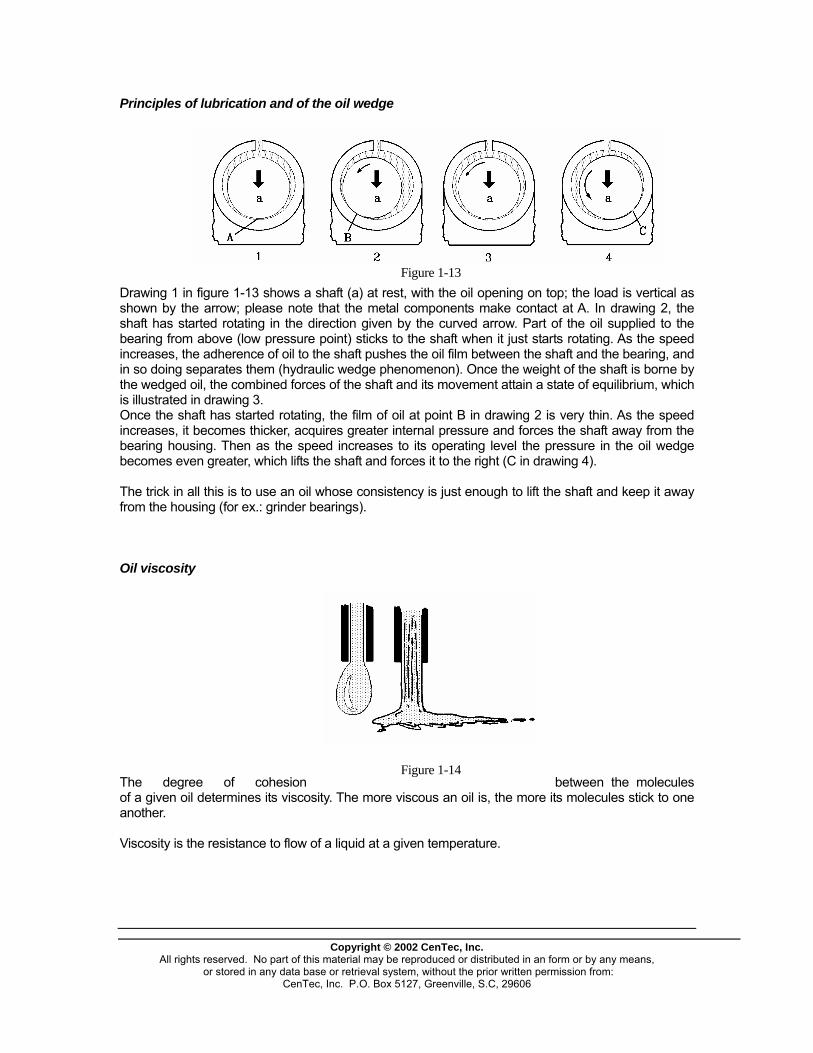
Principles of lubrication and of the oil wedge
Figure 1-13 Drawing 1 in figure 1-13 shows a shaft (a) at rest, with the oil opening on top; the load is vertical as shown by the arrow; please note that the metal components make contact at A. In drawing 2, the shaft has started rotating in the direction given by the curved arrow. Part of the oil supplied to the bearing from above (low pressure point) sticks to the shaft when it just starts rotating. As the speed increases, the adherence of oil to the shaft pushes the oil film between the shaft and the bearing, and in so doing separates them (hydraulic wedge phenomenon). Once the weight of the shaft is borne by the wedged oil, the combined forces of the shaft and its movement attain a state of equilibrium, which is illustrated in drawing 3. Once the shaft has started rotating, the film of oil at point B in drawing 2 is very thin. As the speed increases, it becomes thicker, acquires greater internal pressure and forces the shaft away from the bearing housing. Then as the speed increases to its operating level the pressure in the oil wedge becomes even greater, which lifts the shaft and forces it to the right (C in drawing 4). The trick in all this is to use an oil whose consistency is just enough to lift the shaft and keep it away from the housing (for ex.: grinder bearings). Oil viscosity
Copyright © 2002 CenTec, Inc.
All rights reserved. No part of this material may be reproduced or distributed in an form or by any means, or stored in any data base or retrieval system, without the prior written permission from:
CenTec, Inc. P.O. Box 5127, Greenville, S.C, 29606
The degree of cohesion between the molecules of a given oil determines its viscosity. The more viscous an oil is, the more its molecules stick to one another.
Figure 1-14
Viscosity is the resistance to flow of a liquid at a given temperature.

Viscosity varies with temperature: - the colder the oil, the thicker it becomes; - the warmer the oil, the thinner it becomes. There are two ways to express viscosity: kinematic viscosity and absolute (or dynamic) viscosity. Kinematic viscosity is used more than absolute viscosity, and relates to the time it takes for 60 millilitres of oil to flow out of a capillary tube (0.012 in.). The measuring unit is the "centistoke" (cSt) or the "Saybolt Universal Second" (SUS). NOTE: Viscosity varies from one type of oil to another. Viscosity index The viscosity index is the measure of the viscosity change in function of temperature. The smaller the variation caused by temperature, the greater is the viscosity index. Example: An oil which is viscous at 100oC and remains so at 0oC has a greater viscosity index than another oil which is viscous at 100oC but congealed at 0oC. NOTE: Lubricants have a number of properties. Extra thick oil
Copyright © 2002 CenTec, Inc.
All rights reserved. No part of this material may be reproduced or distributed in an form or by any means, or stored in any data base or retrieval system, without the prior written permission from:
CenTec, Inc. P.O. Box 5127, Greenville, S.C, 29606
The term "thick" applies to an oil whose cohesion factor between molecules is very high. The force with which the outer planes adhere to the mobile parts is not sufficient to break the strength of the film. This leads to incomplete and insufficient lubrication because the wedging process cannot produce an oil film that will separate in enough planes. Under such conditions, the bearing lacks oil and deteriorates.
Figure 1-15
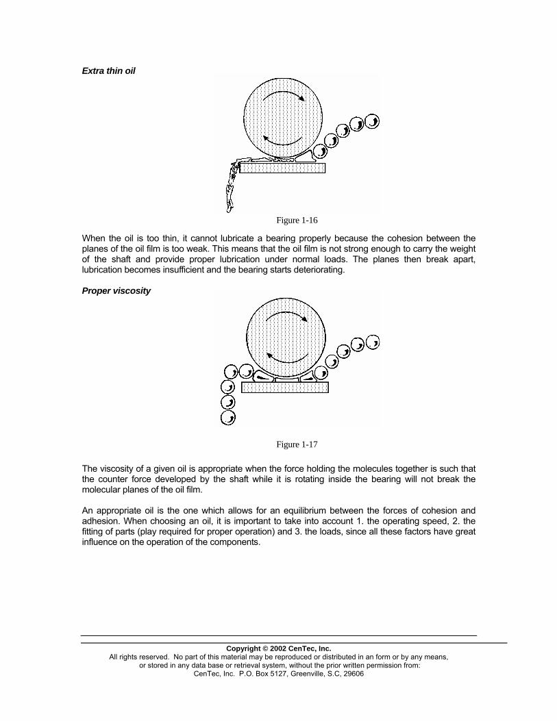
Extra thin oil
Copyright © 2002 CenTec, Inc.
All rights reserved. No part of this material may be reproduced or distributed in an form or by any means, or stored in any data base or retrieval system, without the prior written permission from:
CenTec, Inc. P.O. Box 5127, Greenville, S.C, 29606
Figure 1-16
When the oil is too thin, it cannot lubricate a bearing properly because the cohesion between the planes of the oil film is too weak. This means that the oil film is not strong enough to carry the weight of the shaft and provide proper lubrication under normal loads. The planes then break apart, lubrication becomes insufficient and the bearing starts deteriorating. Proper viscosity
Figure 1-17
The viscosity of a given oil is appropriate when the force holding the molecules together is such that the counter force developed by the shaft while it is rotating inside the bearing will not break the molecular planes of the oil film. An appropriate oil is the one which allows for an equilibrium between the forces of cohesion and adhesion. When choosing an oil, it is important to take into account 1. the operating speed, 2. the fitting of parts (play required for proper operation) and 3. the loads, since all these factors have great influence on the operation of the components.
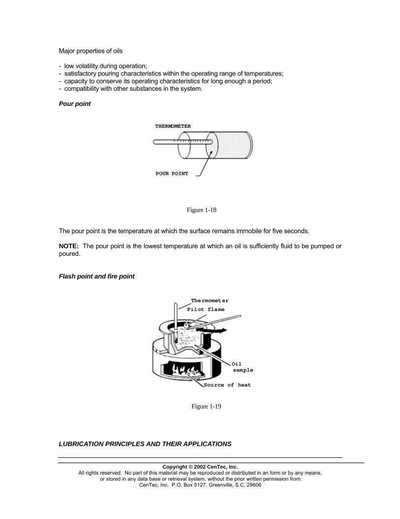
Major properties of oils - low volatility during operation; - satisfactory pouring characteristics within the operating range of temperatures; - capacity to conserve its operating characteristics for long enough a period; - compatibility with other substances in the system. Pour point
THERMOMETER
POUR POINT
Figure 1-18
The pour point is the temperature at which the surface remains immobile for five seconds. NOTE: The pour point is the lowest temperature at which an oil is sufficiently fluid to be pumped or poured. Flash point and fire point
Thermometer
Pilot flame
Oilsample
Source of heat
Figure 1-19 LUBRICATION PRINCIPLES AND THEIR APPLICATIONS
Copyright © 2002 CenTec, Inc.
All rights reserved. No part of this material may be reproduced or distributed in an form or by any means, or stored in any data base or retrieval system, without the prior written permission from:
CenTec, Inc. P.O. Box 5127, Greenville, S.C, 29606

Drop lubrication There are a number of ways to apply lubricants drop by drop, mainly oilcans and single or multiplehole distributors. Drop lubrication applications The oil can method is particularly suitable for mechanisms having short, periodical cycles of work. This application should be made when the stress on the machine is at its lowest.
Figure 31
NOTE : For worker safety, this must be done when the mechanism is at a standstill and the drive motor padlocked, as per company regulations.
Copyright © 2002 CenTec, Inc.
All rights reserved. No part of this material may be reproduced or distributed in an form or by any means, or stored in any data base or retrieval system, without the prior written permission from:
CenTec, Inc. P.O. Box 5127, Greenville, S.C, 29606
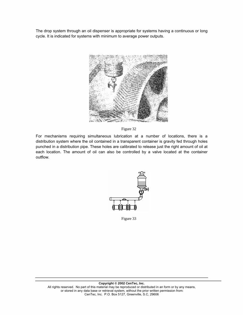
The drop system through an oil dispenser is appropriate for systems having a continuous or long cycle. It is indicated for systems with minimum to average power outputs.
Figure 32
For mechanisms requiring simultaneous lubrication at a number of locations, there is a distribution system where the oil contained in a transparent container is gravity fed through holes punched in a distribution pipe. These holes are calibrated to release just the right amount of oil at each location. The amount of oil can also be controlled by a valve located at the container outflow.
Figure 33
Copyright © 2002 CenTec, Inc.
All rights reserved. No part of this material may be reproduced or distributed in an form or by any means, or stored in any data base or retrieval system, without the prior written permission from:
CenTec, Inc. P.O. Box 5127, Greenville, S.C, 29606

Brush lubrication Usually, brush lubrication applies to lowspeed equipment requiring heavy oil which will stick to gear teeth or chain links.
Figure 34 This kind of lubrication must be done when the mechanisms are at rest and the motor breakers are open and padlocked, or according to your plant's padlocking regulations. Spray lubrication Spray lubrication is a popular technique used to ensure better oil penetration. It also applies to systems requiring continuous lubrication. On small mechanical equipment, spray can oiling gives good and deep lubrication.
Copyright © 2002 CenTec, Inc.
All rights reserved. No part of this material may be reproduced or distributed in an form or by any means, or stored in any data base or retrieval system, without the prior written permission from:
CenTec, Inc. P.O. Box 5127, Greenville, S.C, 29606
Usually, this type of lubrication is done when the equipment is at rest.
Figure 35
For heavier equipment, such as a large speed reducer, an automatic spraying device is installed in the base. It also serves as the oil reservoir.
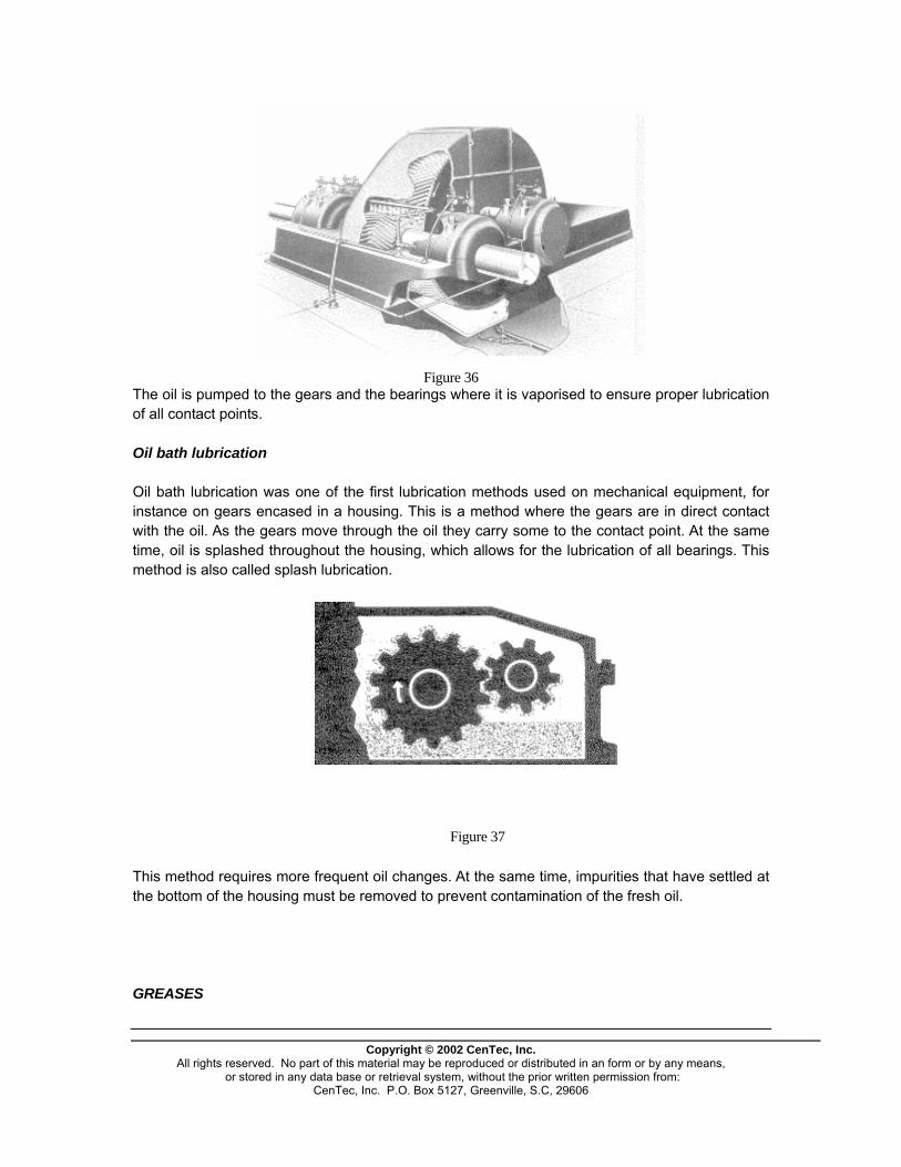
Figure 36 The oil is pumped to the gears and the bearings where it is vaporised to ensure proper lubrication of all contact points. Oil bath lubrication Oil bath lubrication was one of the first lubrication methods used on mechanical equipment, for instance on gears encased in a housing. This is a method where the gears are in direct contact with the oil. As the gears move through the oil they carry some to the contact point. At the same time, oil is splashed throughout the housing, which allows for the lubrication of all bearings. This method is also called splash lubrication.
his method requires more frequent oil changes. At the same time, impurities that have settled at
REASES
Figure 37
Tthe bottom of the housing must be removed to prevent contamination of the fresh oil. G
Copyright © 2002 CenTec, Inc.
All rights reserved. No part of this material may be reproduced or distributed in an form or by any means, or stored in any data base or retrieval system, without the prior written permission from:
CenTec, Inc. P.O. Box 5127, Greenville, S.C, 29606

Copyright © 2002 CenTec, Inc.
All rights reserved. No part of this material may be reproduced or distributed in an form or by any means, or stored in any data base or retrieval system, without the prior written permission from:
CenTec, Inc. P.O. Box 5127, Greenville, S.C, 29606
reases are solid or semi-solid lubricants. They are made by dispersing thickeners in a liquid
- ordinary greases;
rdinary greases are mineral oils that have been thickened with metallic soap, which is obtained by
rease manufacturing requires the use of a third component: organic or inorganic additives.
he following chart presents the major components of greases:
Glubricant. There are usually two types of greases on the market: - complex greases. Ocombining fats (animal or vegetable) with a metal or mineral. The most frequently used elements for this purpose are calcium, sodium, lithium and aluminium. G T
FLUIDS THICKENERS SPECIAL INGREDIENTS
Mineral
s
Organic unds
Soap , sodium
Strontium
Microgel (clay)
ounds
Oxidation inhi
ndex) improvers
erfumes
tion interrupter
s Oils Ester compo Ethers Glycols Silicones
Lithium Barium, calcium Carbon black Silica gel Urea comp Terephlamate Organic dies
bitor Rust inhibitor V.I. (viscosity i PDies Metal-reac
his chart shows that it takes a wide range of greases to meet a vast array of operating Tconditions.

Copyright © 2002 CenTec, Inc.
All rights reserved. No part of this material may be reproduced or distributed in an form or by any means, or stored in any data base or retrieval system, without the prior written permission from:
CenTec, Inc. P.O. Box 5127, Greenville, S.C, 29606
These operating conditions are dictated by the physical characteristics of a mechanism, the type of movement and the degree of watertightness, or by the need for the lubricant to also be a tightening agent to prevent lubricant loss or foreign substance penetration. Since they are solid, greases do not cool nor cleanse as an oil does. Beyond these limitations, greases have virtually all the other functions of lubricating fluids. For a given application, a grease must: - provide appropriate lubrication to reduce friction and the wear of surfaces that
come in contact; - protect against corrosion; - be a tightening agent by preventing the penetration of water and foreign
substances; - prevent leaks, scaling and other losses from lubricated surfaces; - resist unacceptable structure or consistence changes due to mechanical
constraints during prolonged use; - resist hardening which causes extra resistance to the movement of
components during cold spells; - offer physical characteristics suitable for the method of application; - be compatible with elastomer joints or with other lubricated components in
the mechanism; - tolerate some contamination, such as humidity, without losing its major
characteristics. How do greases lubricate? When the mobile components of a bearing come into contact with the grease, a small quantity of oil expressed from the grease ensures the lubrication of the bearing surface. This oil gradually breaks down due to oxidation or is lost by evaporation or under the effect of the centrifugal force.
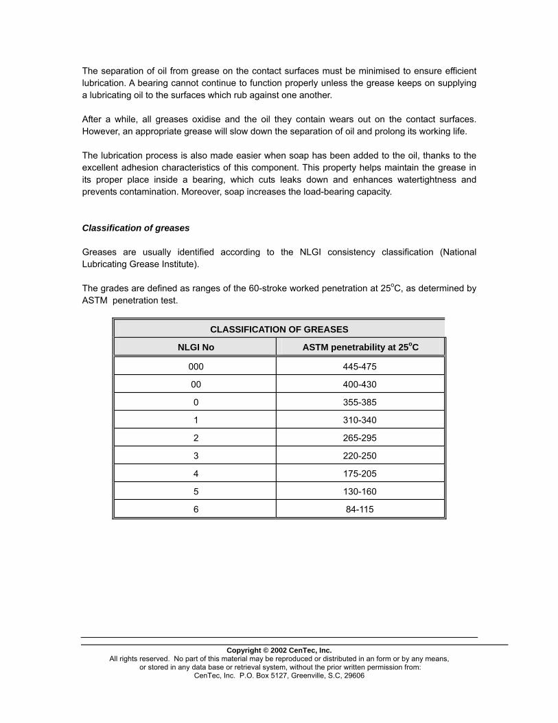
Copyright © 2002 CenTec, Inc.
All rights reserved. No part of this material may be reproduced or distributed in an form or by any means, or stored in any data base or retrieval system, without the prior written permission from:
CenTec, Inc. P.O. Box 5127, Greenville, S.C, 29606
The separation of oil from grease on the contact surfaces must be minimised to ensure efficient lubrication. A bearing cannot continue to function properly unless the grease keeps on supplying a lubricating oil to the surfaces which rub against one another. After a while, all greases oxidise and the oil they contain wears out on the contact surfaces. However, an appropriate grease will slow down the separation of oil and prolong its working life. The lubrication process is also made easier when soap has been added to the oil, thanks to the excellent adhesion characteristics of this component. This property helps maintain the grease in its proper place inside a bearing, which cuts leaks down and enhances watertightness and prevents contamination. Moreover, soap increases the load-bearing capacity. Classification of greases Greases are usually identified according to the NLGI consistency classification (National Lubricating Grease Institute). The grades are defined as ranges of the 60-stroke worked penetration at 25oC, as determined by ASTM penetration test.
CLASSIFICATION OF GREASES
NLGI No ASTM penetrability at 25oC
000 445-475
00 400-430
0 355-385
1 310-340
2 265-295
3 220-250
4 175-205
5 130-160
6 84-115
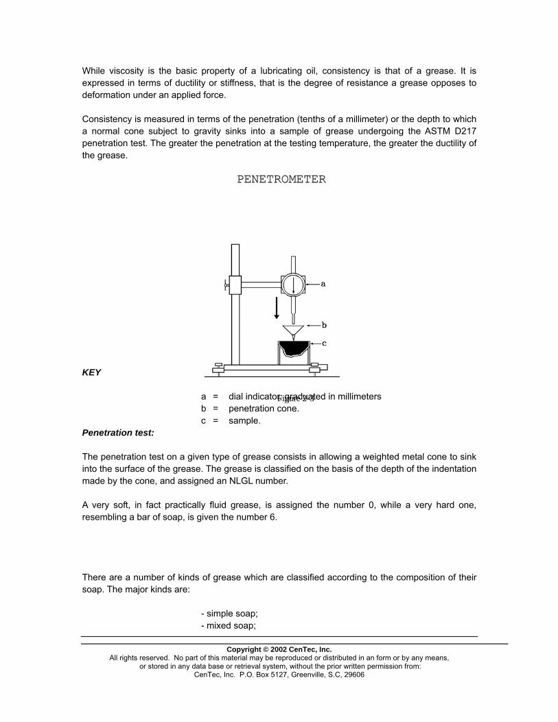
While viscosity is the basic property of a lubricating oil, consistency is that of a grease. It is expressed in terms of ductility or stiffness, that is the degree of resistance a grease opposes to deformation under an applied force. Consistency is measured in terms of the penetration (tenths of a millimeter) or the depth to which a normal cone subject to gravity sinks into a sample of grease undergoing the ASTM D217 penetration test. The greater the penetration at the testing temperature, the greater the ductility of the grease.
Copyright © 2002 CenTec, Inc.
All rights reserved. No part of this material may be reproduced or distributed in an form or by any means, or stored in any data base or retrieval system, without the prior written permission from:
CenTec, Inc. P.O. Box 5127, Greenville, S.C, 29606
KEY a = dial indicator, graduated in millimeters b = penetration cone.
Figure 2-3
c = sample. Penetration test: The penetration test on a given type of grease consists in allowing a weighted metal cone to sink into the surface of the grease. The grease is classified on the basis of the depth of the indentation made by the cone, and assigned an NLGL number. A very soft, in fact practically fluid grease, is assigned the number 0, while a very hard one, resembling a bar of soap, is given the number 6. There are a number of kinds of grease which are classified according to the composition of their soap. The major kinds are: - simple soap; - mixed soap;
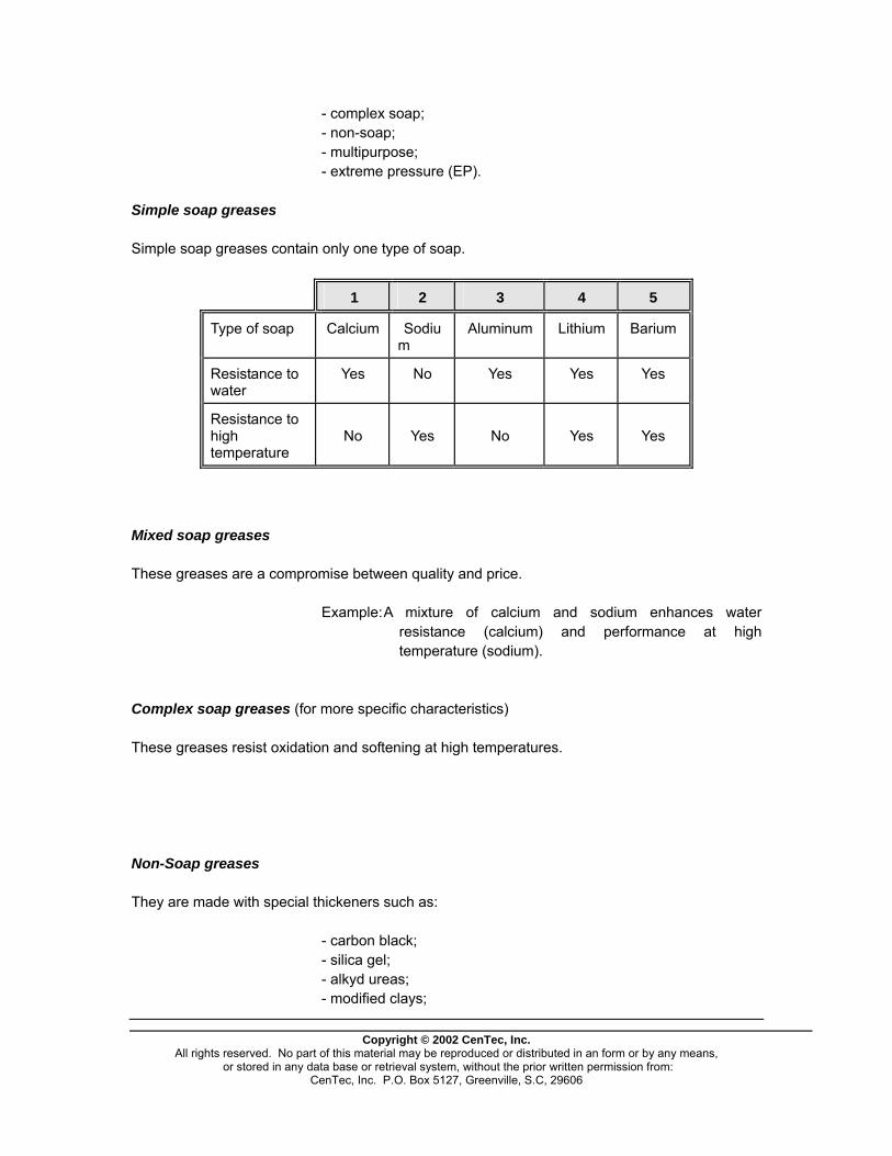
Copyright © 2002 CenTec, Inc.
All rights reserved. No part of this material may be reproduced or distributed in an form or by any means, or stored in any data base or retrieval system, without the prior written permission from:
CenTec, Inc. P.O. Box 5127, Greenville, S.C, 29606
- complex soap; - non-soap; - multipurpose; - extreme pressure (EP). Simple soap greases Simple soap greases contain only one type of soap.
1 2 3 4 5
Type of soap Calcium Sodium
Aluminum Lithium Barium
Resistance to water
Yes No Yes Yes Yes
Resistance to high temperature
No
Yes
No
Yes
Yes
Mixed soap greases These greases are a compromise between quality and price. Example: A mixture of calcium and sodium enhances water
resistance (calcium) and performance at high temperature (sodium).
Complex soap greases (for more specific characteristics) These greases resist oxidation and softening at high temperatures. Non-Soap greases They are made with special thickeners such as: - carbon black; - silica gel; - alkyd ureas; - modified clays;
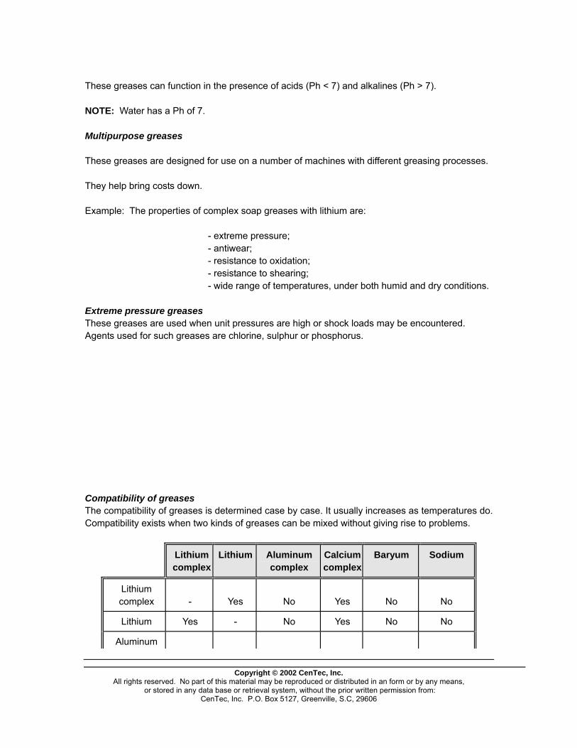
Copyright © 2002 CenTec, Inc.
All rights reserved. No part of this material may be reproduced or distributed in an form or by any means, or stored in any data base or retrieval system, without the prior written permission from:
CenTec, Inc. P.O. Box 5127, Greenville, S.C, 29606
These greases can function in the presence of acids (Ph < 7) and alkalines (Ph > 7). NOTE: Water has a Ph of 7. Multipurpose greases These greases are designed for use on a number of machines with different greasing processes. They help bring costs down. Example: The properties of complex soap greases with lithium are: - extreme pressure; - antiwear; - resistance to oxidation; - resistance to shearing; - wide range of temperatures, under both humid and dry conditions. Extreme pressure greases These greases are used when unit pressures are high or shock loads may be encountered. Agents used for such greases are chlorine, sulphur or phosphorus. Compatibility of greases The compatibility of greases is determined case by case. It usually increases as temperatures do. Compatibility exists when two kinds of greases can be mixed without giving rise to problems.
Lithium complex
Lithium Aluminum complex
Calcium complex
Baryum Sodium
Lithium complex
-
Yes
No
Yes
No
No
Lithium Yes - No Yes No No
Aluminum

Copyright © 2002 CenTec, Inc.
All rights reserved. No part of this material may be reproduced or distributed in an form or by any means, or stored in any data base or retrieval system, without the prior written permission from:
CenTec, Inc. P.O. Box 5127, Greenville, S.C, 29606
complex No No - No No No
Calcium complex
Yes
Yes
No
-
Yes
No
Baryum No No No Yes - No
Sodium No No No No No -
Major properties of greases Dropping point The temperature at which it switches from the semi-solid form to the liquid form. This is an important test which helps decide on the type of grease to use for a specific application. Pumpability The lowest temperature at which a grease remains pumpable. It is useless to apply grease that will remain rigid at operating temperatures. Consistency Measures the oiliness or hardness of grease, or the resistance to deformation when a force is applied; Resistance to shearing The capacity of an oil to maintain its consistency under mechanical constraints. As speed increases, the structure of the grease changes to the point that its consistency is modified; Bleeding
Copyright © 2002 CenTec, Inc.
All rights reserved. No part of this material may be reproduced or distributed in an form or by any means, or stored in any data base or retrieval system, without the prior written permission from:
CenTec, Inc. P.O. Box 5127, Greenville, S.C, 29606
It is used to determine the percentage of oil which separates, at rest, from its soap base. However, this does not measure the separation under dynamic conditions; Hightemperature stability The capacity to maintain its consistency, structure and performance under high temperatures; Resistance to oxidation The capacity of a grease to resist to chemical reactions involving oxygen. Oxidised oils contain waterproof resins which darken greases and can make them corrosive for certain metals; Lowtemperature pumping The capacity of a grease to flow and ensure proper lubrication under lowtemperature operation. Wear resistance capacity that a grease to protect against abrasion stemming from metaltometal contact under overload conditions; Etreme pressure The capacity to protect metallic surfaces, while they are sliding against one another and bearing heavy loads, against seizure, thus against wear; Rsistance to water Water can severely alter the structure of an oil. Under homogenising conditions, water will dilute and liquefy the grease. In such cases, the grease should include some calcium or lithium soap which will not dissolve in water. Rsistance to corrosion Tthe capacity to protect surfaces against the chemical attacks of water or other contaminants. Grease selection Choosing a grease depends on a number of factors: the load, which exerts a pressure; the operating speed of components, which affects the operating temperature; the environment in which the machine is set. Load The load is the amount of force against which the grease has to operate. This also involves the pressure or weight to which the grease is subjected when the machine is at rest. The bearings of a highspeed line shaft in an airconditioning system will be subjected to higher loads than those of a line shaft which turns slowly in the same system. Speed As speed increases, surface wear also increases. In order to slow this deterioration when surfaces are subjected to rapid movement, the grease will have to be chosen in view of counterbalancing the pressure increase. Temperature Temperature has a definite and considerable impact on oils and greases. Grease thickens as temperature drops, and thins out as it rises. Today, it is possible to select a grease which will meet the operating requirements of a system through the full range of temperatures that can be encountered. Environment

Copyright © 2002 CenTec, Inc.
All rights reserved. No part of this material may be reproduced or distributed in an form or by any means, or stored in any data base or retrieval system, without the prior written permission from:
CenTec, Inc. P.O. Box 5127, Greenville, S.C, 29606
The environment in which a grease is used can have a considerable impact on the selection. For instance, it will have to protect against the corrosive action of acids if contact with such substances is inevitable.

Copyright © 2002 CenTec, Inc.
All rights reserved. No part of this material may be reproduced or distributed in an form or by any means, or stored in any data base or retrieval system, without the prior written permission from:
CenTec, Inc. P.O. Box 5127, Greenville, S.C, 29606
Comparative advantages of oils and greases Advantages of oil It humidifies surfaces because of its fluidity; it can remove contaminants and dirts (with filters); it evacuates heat produced by bearings; it is ideally suited for lubrication. Advantages of grease It simplifies the design on component housings; it does not require reapplication as often; it does a better job of keeping contaminants out; it slowly releases the liquid lubricant, thus reducing friction and wear; it protects against water and abrasives; it maintains its consistency under mechanical stress; it sticks to mechanical components; it protects against corrosion; it enhances watertightness. Disposal of used oil- SAFETY FIRST Each plant has its own regulations regarding the safe disposal of used or contaminated oils. These regulations must meet environmental laws. Whatever the applicable regulations and laws, nature's lifesupporting systems will suffer more and more if workers are not made aware of environmental problems stemming from improper disposal of contaminated products. Each worker must make the effort to become informed as to the means and ways of recovering used products. Obviously, it is much easier to turn one's head away when leaked products are making their way to the plant's sewer. It is the duty of all workers to inform those people who are in charge of environmental matters at the plant when they see that contaminants have leaked from a pipe or a machine.

Grease lubrication As described earlier, grease is made with mineral oils that have been thickened with a metallic soap. Its consistency precludes the application methods appropriate for oil. It can be applied by hand directly on the bearings before assembly or with a greasing gun or grease cup.
Figure 310
There are other methods, of which the following. Lubrication with preloaded cup When their installation is possible, preloaded cups eliminate the need to clean and take care of a grease bucket or to use a greasing gun. Before installing a preloaded cup, the conduits leading to the greasing nozzle must be filled with grease.
Copyright © 2002 CenTec, Inc.
All rights reserved. No part of this material may be reproduced or distributed in an form or by any means, or stored in any data base or retrieval system, without the prior written permission from:
CenTec, Inc. P.O. Box 5127, Greenville, S.C, 29606
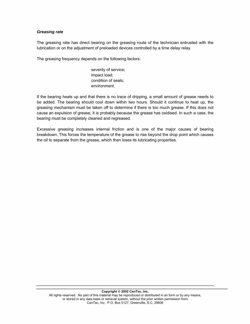
Copyright © 2002 CenTec, Inc.
All rights reserved. No part of this material may be reproduced or distributed in an form or by any means, or stored in any data base or retrieval system, without the prior written permission from:
CenTec, Inc. P.O. Box 5127, Greenville, S.C, 29606
Greasing rate The greasing rate has direct bearing on the greasing route of the technician entrusted with the lubrication or on the adjustment of preloaded devices controlled by a time delay relay. The greasing frequency depends on the following factors: severity of service; impact load; condition of seals; environment. If the bearing heats up and that there is no trace of dripping, a small amount of grease needs to be added. The bearing should cool down within two hours. Should it continue to heat up, the greasing mechanism must be taken off to determine if there is too much grease. If this does not cause an expulsion of grease, it is probably because the grease has oxidised. In such a case, the bearing must be completely cleaned and regreased. Excessive greasing increases internal friction and is one of the major causes of bearing breakdown. This forces the temperature of the grease to rise beyond the drop point which causes the oil to separate from the grease, which then loses its lubricating properties.
If the bearing housing is not equipped with a vent, extra care is required when greasing with a gun to prevent the rupture of seals. Such guns can create pressures of up to 10,000 lbs/sq. in. (68,970 kPa). Greasing of bearings equipped with vents 1. Remove the vent cap when the bearing is not operating; 2. Inject new grease in the housing until it spills out through the vent; 3. Leaving the vent cap off, rotate the bearing slowly for one or two minutes
to allow excess grease to flow out; 4. Put the vent cap back on and clean the outside of the housing; 5. After a few hours of operation, check to see that the temperature of the
bearing is normal. Grease should fill the bearing, or at least two-thirds of the space inside the housing.
DRY LUBRICANTS, THEIR CHARACTERISTICS AND APPLICATIONS Dryfilm lubricants Dryfilm lubricants are powders that are placed between moving surfaces to ensure their lubrication and to take advantage of their low resistance to shearing. Under some operating conditions they offer
Copyright © 2002 CenTec, Inc.
All rights reserved. No part of this material may be reproduced or distributed in an form or by any means, or stored in any data base or retrieval system, without the prior written permission from:
CenTec, Inc. P.O. Box 5127, Greenville, S.C, 29606
Copyright © 2002 CenTec, Inc.
All rights reserved. No part of this material may be reproduced or distributed in an form or by any means, or stored in any data base or retrieval system, without the prior written permission from:
CenTec, Inc. P.O. Box 5127, Greenville, S.C, 29606
significant advantages. Major dryfilm lubricants Graphite, which owes its lubricating properties to its lamellar crystalline structure, needs oxygen and water to be effective. At about 550oC, graphite combines with atmospheric oxygen to produce carbon dioxide. Molybdenum disulphide (MoS2) is a natural product found in iron ore. Before it can be used as a lubricant, it has to be purified to a very high degree to separate it fully from its abrasive gangue. It is also lamellar and works along the same principles as graphite. In the presence of air, it is efficient up to about 400oC. At higher temperatures it combines with air to give MoO3, an abrasive substance. When operating under a vacuum, it keeps its lubricating properties. Polytetrafluoroethylene (Teflon) is a thermoplastic substance. Since its surface energy is very low, it has very little tendency to stick to other materials. This property gives it its "greasy feel" and its low friction coefficient. As for all thermoplastic materials, it can only used at relatively low temperatures (under 300oC). Use of lubricating powders Lubricating powders are recommended when: pressures are very high; the chemical environment is harsh (radiation, pumps for acids, etc.); electric resistivity needs to be very low (breaker pins, etc.); checking for contamination (food, textile, etc.); checking for friction (contact corrosion). However, such lubricants have their limitations: relatively high friction coefficient (about 0.02 to 0.3) short life span of lubricating film (103 to 106 cycles); absence of contribution to heat evacuation. Application of lubricating powders The most frequent methods used in applying powder lubricants on surfaces and making them stay in place are: rubbing, incorporation to a resin or other binding agent and chemical reaction. Rubbing The surfaces are rubbed with fine powder, which makes it stick between the microscopic asperities on the surfaces that require lubrication. This type of lubrication is short lived and its efficiency is low. Incorporation into a resin or other bonding agent

Copyright © 2002 CenTec, Inc.
All rights reserved. No part of this material may be reproduced or distributed in an form or by any means, or stored in any data base or retrieval system, without the prior written permission from:
CenTec, Inc. P.O. Box 5127, Greenville, S.C, 29606
For lowoperating temperatures (<250oC) phenolic, epoxy or polyamide resins are used as bonding agents. At higher temperatures, metallic salts or ceramics are preferred. These compounds are usually applied in layers of less than 102 mm (0.01 mm). This very popular method is efficient. Major applications of lubricating powders
POWDER USES
Graphite or Molybdenum sulphite (MoS2) with bonding agent
Mechanisms which function once in a while (locks)
Gluedon Teflon Mechanisms which function once in a while (locks) Pump bushings
Lead, indium or cadmium coating (soft metals)
Temporary protection of bushings at startup Breakers
Rubbedon graphite or Molybdenum sulphite
Coldmetal working (forming, stamping, stretching)
Compounds produced by chemical reaction with chlorine, phosphorus or sulphur
Hotmetal working

DRAWINGS and BLUEPRINTS
Copyright © 2002 CenTec, Inc.
All rights reserved. No part of this material may be reproduced or distributed in an form or by any means, or stored in any data base or retrieval system, without the prior written permission from:
CenTec, Inc. P.O. Box 5127, Greenville, S.C, 29606
Copyright © 2002 CenTec, Inc.
All rights reserved. No part of this material may be reproduced or distributed in an form or by any means, or stored in any data base or retrieval system, without the prior written permission from:
CenTec, Inc. P.O. Box 5127, Greenville, S.C, 29606
INTERPRETATION OF THE GRAPHICS LANGUAGE AS SHOWN ON MECHANICAL BLUEPRINTS
Since time immemorial, man has always tried to transmit his thoughts and to express them through drawings to ensure their endurance. The first writing techniques, such as the hieroglyphics of the Egyptians, were drawings or graphs. Thus, a graph is the expression of a concept through the use of lines made on a surface. This definition fits perfectly the representation of an object via a drawing. Finally, this language, which will be understood by people speaking different languages, is used universally to communicate ideas and feelings. Drawing has greatly evolved over the centuries and, today, falls under two broad categories, each having its own purpose: artistic drawing, which expresses figurative or non-figurative ideas for cultural or commercial ends; industrial drawing which, whatever the industrial sector, transmits technical or practical ideas. Many people have to read blueprints. Even in everyday life, a grasp of mechanical drawing
will prove very useful to understand the plans of a house, the assembly, maintenance and instructions pertaining to the operation of many manufactured products, as well as assembly and operation plans and instructions of various appliances.

Copyright © 2002 CenTec, Inc.
All rights reserved. No part of this material may be reproduced or distributed in an form or by any means, or stored in any data base or retrieval system, without the prior written permission from:
CenTec, Inc. P.O. Box 5127, Greenville, S.C, 29606
WHAT IS MECHANICAL DRAWING?
On many occasions in our everyday life, we find it necessary to exchange information in some sort of
graphical form. If we can express complex ideas through simple drawings, then our drawings will
allow a much easier transmission and reception of the information that we want to communicate.
This is why we use, for example, a road map to find our way in an unknown area.
Different types of communication aids, characterized by their use of graphics, are used in many
different areas. Mechanical drawing or technical drawing sometimes even called industrial drawing,
is one type of communication aid. It is a real language which is used as an important means of
communication in industrial life. As a matter of fact, it is the communication tool most used by the
craftsmen in industry.
ROLE OF MECHANICAL DRAWING—EVERYDAY LIFE
The usefulness of mechanical drawing is very obvious. A knowledge of drawing, or blueprint
reading, makes it easier for us to understand other types of representations:
• Map reading, diagrams, schematics, etc.
• To make simple sketches (accident reports, where to install a piece of furniture).
• Allows us to better understand the drawings and schematics which we see in current
magazines.
But beyond these practical uses, making drawings and blueprints also has an educational value. It
develops an artistic sense, improves our sense of observation, an develops
precision use of language.
ROLE OF MECHANICAL DRAWING—INDUSTRIAL LIFE
Mechanical drawing is an intermediary between man and:

Copyright © 2002 CenTec, Inc.
All rights reserved. No part of this material may be reproduced or distributed in an form or by any means, or stored in any data base or retrieval system, without the prior written permission from:
CenTec, Inc. P.O. Box 5127, Greenville, S.C, 29606
• the item to be made (to go from an idea to a real thing)
• his work (a means of achieving the work he does)
• those who participate in his work (a means of communicating between all the people on
the work team).
For example, mechanical drawing:
• Lets us know the function, the overall dimensions, and the way to install a machine.
• Shows us the correct position of the different parts and how to place them.
• Gives precise information to the machinists in order for the parts to be made.
• Helps the designer to preview his design.
These are the reasons why you have to know how to read and interpret mechanical drawings, or
blueprints, if you work in industry. The drawing office personnel draftsmen, designers, etc.) must
know even more technical information to prepare the documents.
DIFFERENT KINDS OF DRAWINGS
Because it is an intermediary between the persons who create a machine and the persons who
make it, a drawing can take different forms according to its role and the people who will use it.
• Drawings for fabrication with standardized symbols--for mechanical, welding, buildings,
electrical construction, etc.
• Sketches illustrating an idea, technical principle, description.
• Schematic explaining the operation of machines.
• Electrical, hydraulic, and pneumatic circuits.
• Curves, calculations of graphical statistics.
• Control instrument diagrams.
• Pictorial drawings for better visualization.
Draftsmen to indicate various drawing components use the following line
types:
TECHNOLOGY OF LINES LINE TYPE WIDTH Function

ACONTINUOUS
THICK
0.7 − Visible Edges
B
3 1
BROKEN
SHORT
MEDIUM
0.35 − Hidden Edges
C
MIXED THIN 0.18
− Axis Of Symmetry
− Hole Centers
− Position
− Pitch Circle Diameter
D
CONTINUOUS
THIN
0.18 − Fictitious Edges
− Dimension & Extension Lines
− Leader Lines
− Crosshatching
− Revolved Sections
− Construction
E
BROKEN THIN
LONG
0.18 − Special Hatching
− Architecture
− Demolition
F
MIXED THIN,
HEAVY ENDS &
CORNERS
0.18
0.7 − Cutting Planes
G
MIXED HEAVY 0.7 − Special Surface
Treatment
H
CONTINUOUS
IRREGULAR
THIN
0.18 − Partial Section
− Broken Parts
LINE SAMPLES:
Copyright © 2002 CenTec, Inc.
All rights reserved. No part of this material may be reproduced or distributed in an form or by any means, or stored in any data base or retrieval system, without the prior written permission from:
CenTec, Inc. P.O. Box 5127, Greenville, S.C, 29606
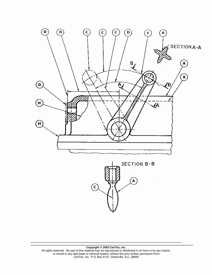
Copyright © 2002 CenTec, Inc.
All rights reserved. No part of this material may be reproduced or distributed in an form or by any means, or stored in any data base or retrieval system, without the prior written permission from:
CenTec, Inc. P.O. Box 5127, Greenville, S.C, 29606
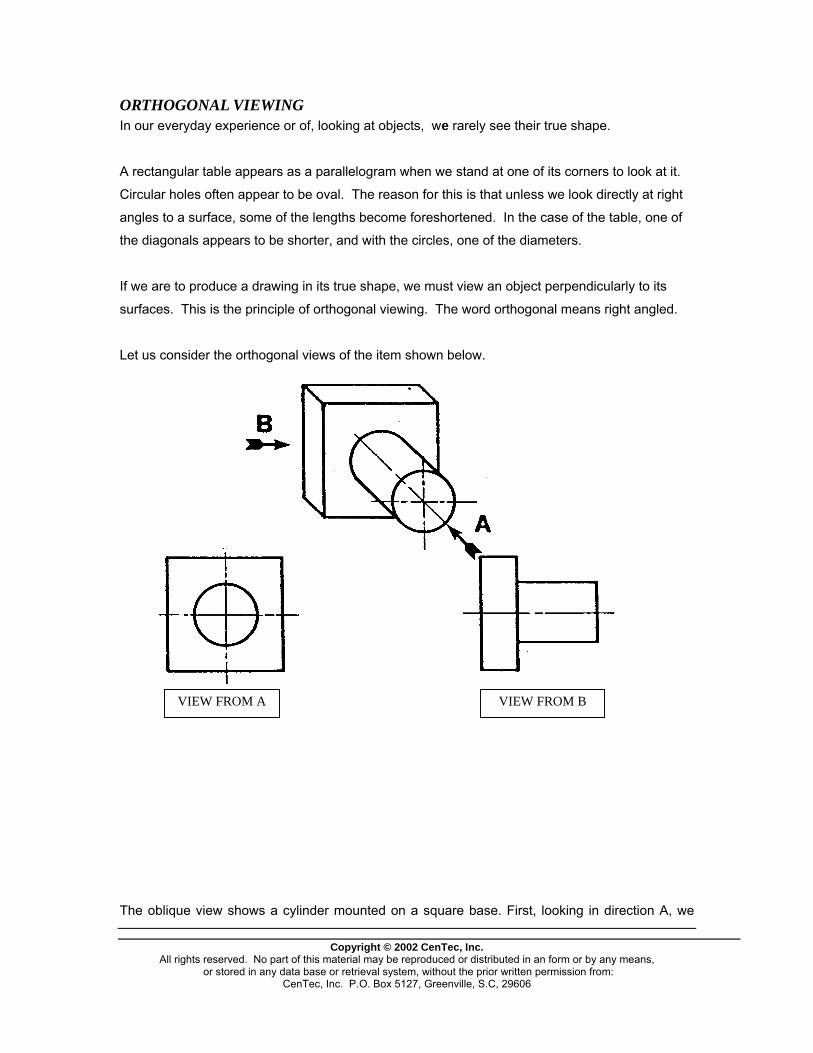
ORTHOGONAL VIEWING In our everyday experience or of, looking at objects, we rarely see their true shape.
A rectangular table appears as a parallelogram when we stand at one of its corners to look at it.
Circular holes often appear to be oval. The reason for this is that unless we look directly at right
angles to a surface, some of the lengths become foreshortened. In the case of the table, one of
the diagonals appears to be shorter, and with the circles, one of the diameters.
If we are to produce a drawing in its true shape, we must view an object perpendicularly to its
surfaces. This is the principle of orthogonal viewing. The word orthogonal means right angled.
Let us consider the orthogonal views of the item shown below.
VIEW FROM A VIEW FROM B
The oblique view shows a cylinder mounted on a square base. First, looking in direction A, we
Copyright © 2002 CenTec, Inc.
All rights reserved. No part of this material may be reproduced or distributed in an form or by any means, or stored in any data base or retrieval system, without the prior written permission from:
CenTec, Inc. P.O. Box 5127, Greenville, S.C, 29606

Copyright © 2002 CenTec, Inc.
All rights reserved. No part of this material may be reproduced or distributed in an form or by any means, or stored in any data base or retrieval system, without the prior written permission from:
CenTec, Inc. P.O. Box 5127, Greenville, S.C, 29606
see a circle for the end of the cylinder. We cannot see any of the curved surface because this is
in a line with our sight and is therefore "lost". Next, we see a square of the base, but again the
thickness has disappeared.
Looking in direction B, we can see a rectangle for the side of the cylinder. No curvature is seen
because all distances from the eye are lost and the ends become straight lines equal in length to
the diameter, thus only a rectangle is seen. it is this type of viewing which we use in making
mechanical drawings.
RECTANGULAR SURFACES
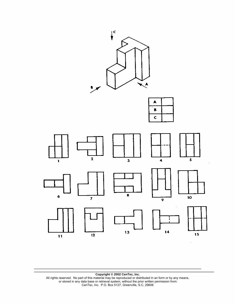
Copyright © 2002 CenTec, Inc.
All rights reserved. No part of this material may be reproduced or distributed in an form or by any means, or stored in any data base or retrieval system, without the prior written permission from:
CenTec, Inc. P.O. Box 5127, Greenville, S.C, 29606
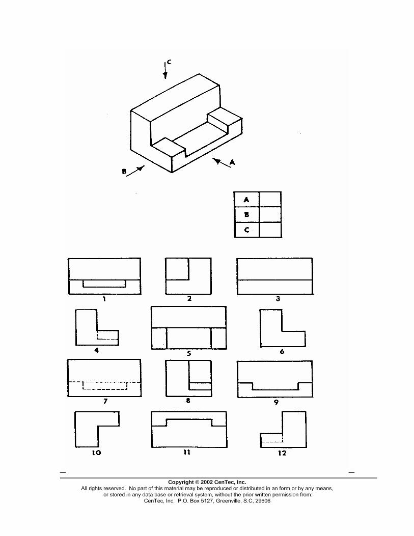
Copyright © 2002 CenTec, Inc.
All rights reserved. No part of this material may be reproduced or distributed in an form or by any means, or stored in any data base or retrieval system, without the prior written permission from:
CenTec, Inc. P.O. Box 5127, Greenville, S.C, 29606
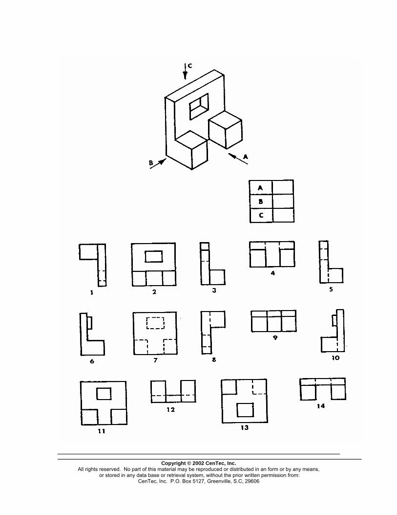
Copyright © 2002 CenTec, Inc.
All rights reserved. No part of this material may be reproduced or distributed in an form or by any means, or stored in any data base or retrieval system, without the prior written permission from:
CenTec, Inc. P.O. Box 5127, Greenville, S.C, 29606
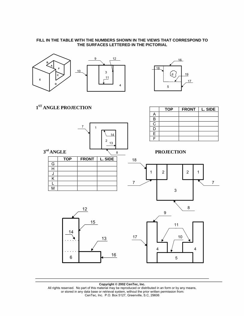
FILL IN THE TABLE WITH THE NUMBERS SHOWN IN THE VIEWS THAT CORRESPOND TO THE SURFACES LETTERED IN THE PICTORIAL
E
BA
F
C
D
3
4
9 12
10
11
5
6
16
18
19
17
1ST ANGLE PROJECTION
Copyright © 2002 CenTec, Inc.
All rights reserved. No part of this material may be reproduced or distributed in an form or by any means, or stored in any data base or retrieval system, without the prior written permission from:
CenTec, Inc. P.O. Box 5127, Greenville, S.C, 29606
TOP FRONT L. SIDE A B C D E F
3rd ANGLE PROJECTION
7
14
13
1
8
2
TOP FRONT L. SIDE G H J K L M
18
7
1 2 2 1
3
7
89
11
1017
4
5
4
12
15
1413
166
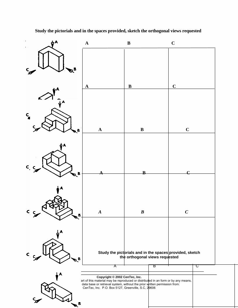
Study the pictorials and in the spaces provided, sketch the orthogonal views requested
A B C
A B C
A B C
A B C
A B C
Study the pictorials and in the spaces provided, sketch the orthogonal views requested
A B C
Copyright © 2002 CenTec, Inc.
t of this material may be reproduced or distributed in an form or by any means, retrieval system, without the prior written permission from:
CenTec, Inc. P.O. Box 5127, Greenville, S.C, 29606
All rights reserved. No par or stored in any data base or

Copyright © 2002 CenTec, Inc.
All rights reserved. No part of this material may be reproduced or distributed in an form or by any means, or stored in any data base or retrieval system, without the prior written permission from:
CenTec, Inc. P.O. Box 5127, Greenville, S.C, 29606
A B C
A B C
A B C
A B C
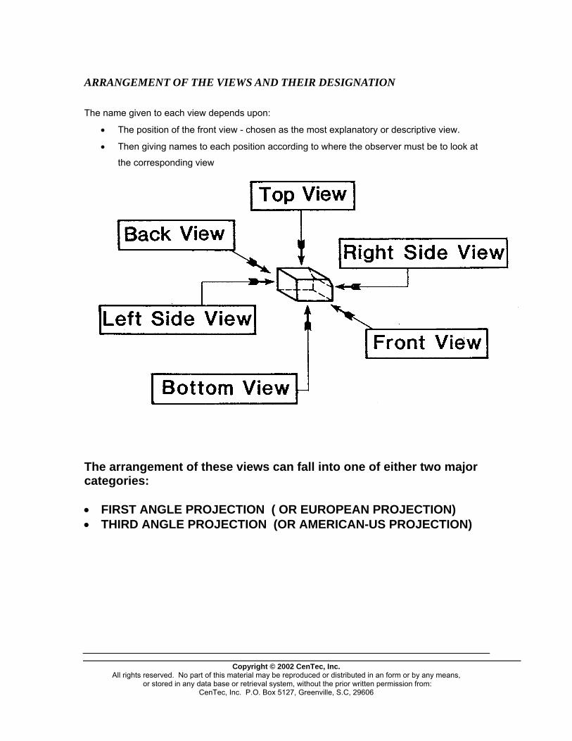
ARRANGEMENT OF THE VIEWS AND THEIR DESIGNATION
The name given to each view depends upon:
• The position of the front view - chosen as the most explanatory or descriptive view.
• Then giving names to each position according to where the observer must be to look at
the corresponding view
The arrangement of these views can fall into one of either two major categories: • FIRST ANGLE PROJECTION ( OR EUROPEAN PROJECTION) • THIRD ANGLE PROJECTION (OR AMERICAN-US PROJECTION)
Copyright © 2002 CenTec, Inc.
All rights reserved. No part of this material may be reproduced or distributed in an form or by any means, or stored in any data base or retrieval system, without the prior written permission from:
CenTec, Inc. P.O. Box 5127, Greenville, S.C, 29606
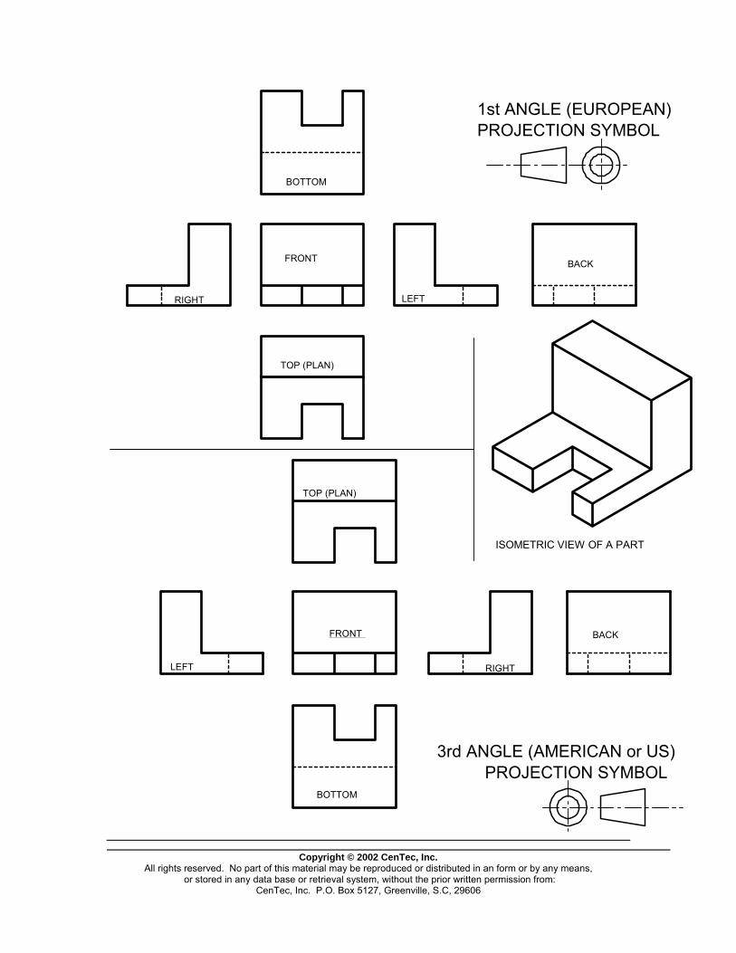
Copyright © 2002 CenTec, Inc.
All rights reserved. No part of this material may be reproduced or distributed in an form or by any means, or stored in any data base or retrieval system, without the prior written permission from:
CenTec, Inc. P.O. Box 5127, Greenville, S.C, 29606
1st ANGLE (EUROPEAN)PROJECTION SYMBOL
PROJECTION SYMBOL3rd ANGLE (AMERICAN or US)
FRONT
LEFTRIGHT
TOP (PLAN)
BACK
BOTTOM
BOTTOM
LEFT
FRONT
RIGHT
BACK
TOP (PLAN)
ISOMETRIC VIEW OF A PART

Copyright © 2002 CenTec, Inc.
All rights reserved. No part of this material may be reproduced or distributed in an form or by any means, or stored in any data base or retrieval system, without the prior written permission from:
CenTec, Inc. P.O. Box 5127, Greenville, S.C, 29606
BACKRIGHT
LEFT
FRONT
BOTTOM
TOP
3rd ANGLE (AMERICAN) PROJECTION
45°
45°45°
45°
MITER LINE VIEW PROJECTION

MITER LINE VIEW PROJECTION1st ANGLE (EUROPEAN) PROJECTION
FRONT BACK
45°
45°45°
45°
RIGHT LEFT
BOTTOM
TOP (PLAN)
Copyright © 2002 CenTec, Inc.
All rights reserved. No part of this material may be reproduced or distributed in an form or by any means, or stored in any data base or retrieval system, without the prior written permission from:
CenTec, Inc. P.O. Box 5127, Greenville, S.C, 29606
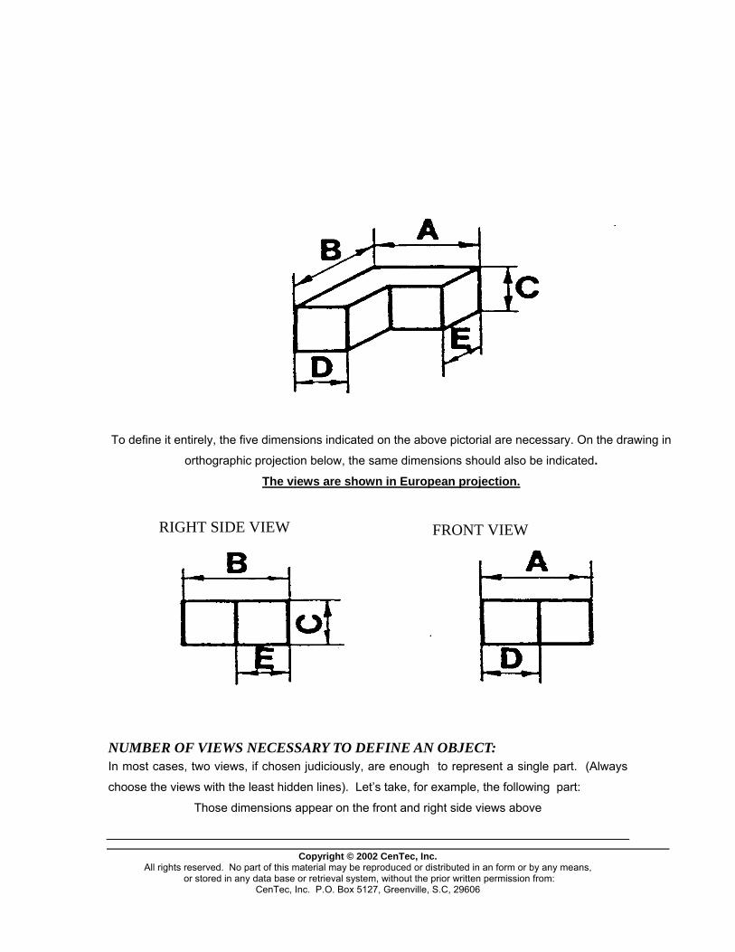
FRONT VIEWRIGHT SIDE VIEW
To define it entirely, the five dimensions indicated on the above pictorial are necessary. On the drawing in
orthographic projection below, the same dimensions should also be indicated. The views are shown in European projection.
NUMBER OF VIEWS NECESSARY TO DEFINE AN OBJECT: In most cases, two views, if chosen judiciously, are enough to represent a single part. (Always
choose the views with the least hidden lines). Let’s take, for example, the following part:
Those dimensions appear on the front and right side views above
Copyright © 2002 CenTec, Inc.
All rights reserved. No part of this material may be reproduced or distributed in an form or by any means, or stored in any data base or retrieval system, without the prior written permission from:
CenTec, Inc. P.O. Box 5127, Greenville, S.C, 29606

The dimensions are well indicated, but the part is not well defined in shape. From the proceeding two views, we can imagine the cut-away in the corner of the part being of several different shapes, as shown below, but still corresponding to the same projections. If the top (or plan) view is used with the front view as indicated, any possible doubt is cleared up.
FRONT
TOP
Copyright © 2002 CenTec, Inc.
All rights reserved. No part of this material may be reproduced or distributed in an form or by any means, or stored in any data base or retrieval system, without the prior written permission from:
CenTec, Inc. P.O. Box 5127, Greenville, S.C, 29606
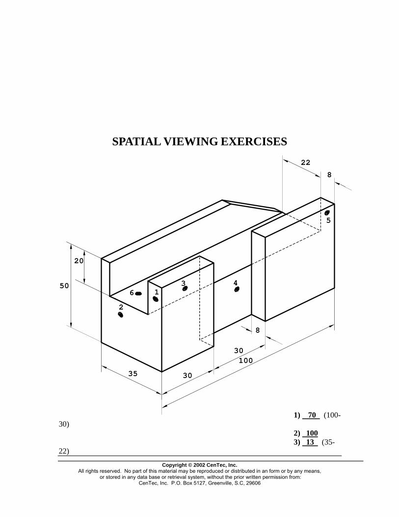
SPATIAL VIEWING EXERCISES
Copyright © 2002 CenTec, Inc.
All rights reserved. No part of this material may be reproduced or distributed in an form or by any means, or stored in any data base or retrieval system, without the prior written permission from:
CenTec, Inc. P.O. Box 5127, Greenville, S.C, 29606
1
2
3 4
5
650
22
35 30
30100
20
8
8
1) 70 (100-30) 2) 100 3) 13 (35-22)

Copyright © 2002 CenTec, Inc.
All rights reserved. No part of this material may be reproduced or distributed in an form or by any means, or stored in any data base or retrieval system, without the prior written permission from:
CenTec, Inc. P.O. Box 5127, Greenville, S.C, 29606
4) 27 (35-8) 5) 8 6) 30 (50-20) INSTRUCTIONS: Above is an isometric view a machined part with 6 dots placed at various locations.

The object is to determine the linear measurement of the thickness of the material behind each dot. In the event a slot or other air space is directly behind the dot, simply deduct the amount of air space as was done on point 3 of the example.
Copyright © 2002 CenTec, Inc.
All rights reserved. No part of this material may be reproduced or distributed in an form or by any means, or stored in any data base or retrieval system, without the prior written permission from:
CenTec, Inc. P.O. Box 5127, Greenville, S.C, 29606
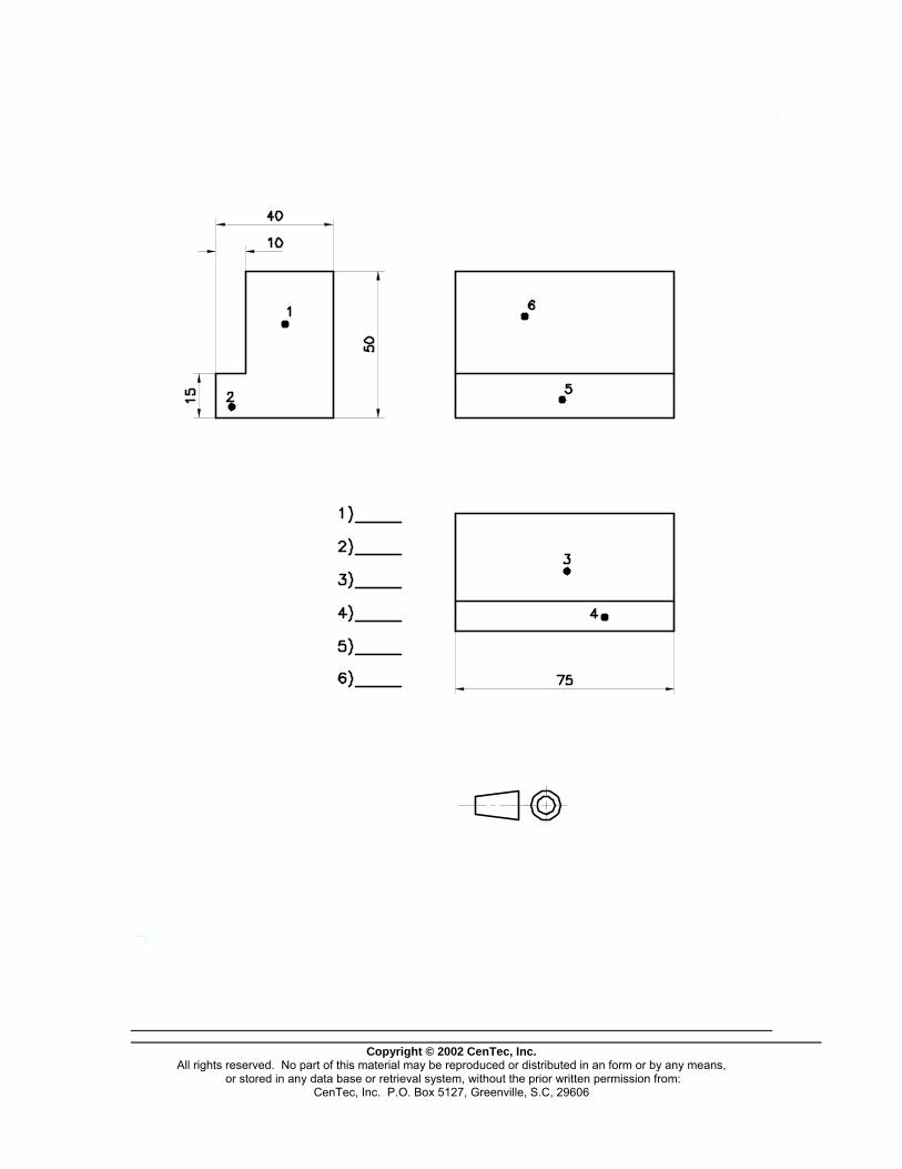
Copyright © 2002 CenTec, Inc.
All rights reserved. No part of this material may be reproduced or distributed in an form or by any means, or stored in any data base or retrieval system, without the prior written permission from:
CenTec, Inc. P.O. Box 5127, Greenville, S.C, 29606

Copyright © 2002 CenTec, Inc.
All rights reserved. No part of this material may be reproduced or distributed in an form or by any means, or stored in any data base or retrieval system, without the prior written permission from:
CenTec, Inc. P.O. Box 5127, Greenville, S.C, 29606
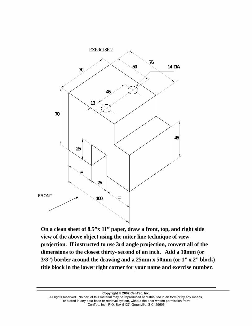
7670
45
70
100
=
25
=
25
13
45
14 DIA.50
EXERCISE 2
FRONT
On a clean sheet of 8.5”x 11” paper, draw a front, top, and right side view of the above object using the miter line technique of view projection. If instructed to use 3rd angle projection, convert all of the dimensions to the closest thirty- second of an inch. Add a 10mm (or 3/8”) border around the drawing and a 25mm x 50mm (or 1” x 2” block) title block in the lower right corner for your name and exercise number.
Copyright © 2002 CenTec, Inc.
All rights reserved. No part of this material may be reproduced or distributed in an form or by any means, or stored in any data base or retrieval system, without the prior written permission from:
CenTec, Inc. P.O. Box 5127, Greenville, S.C, 29606
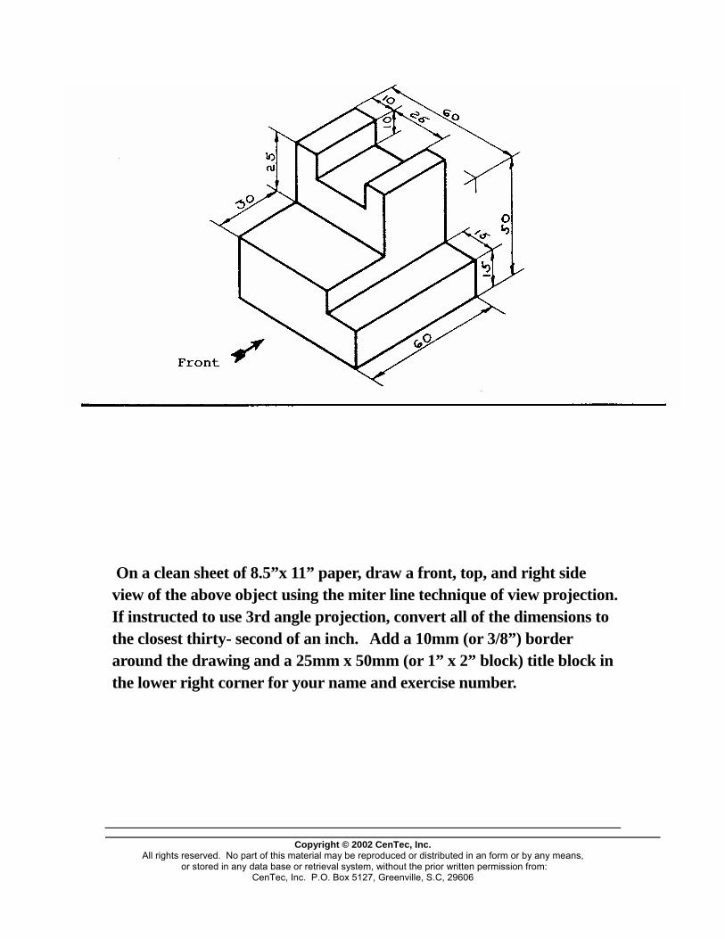