mechanically fastened roofing systems - sika group | · pdf fileour local sika companies in...
TRANSCRIPT

Sika Technology and Concepts for
Mechanically Fastened Roofi ng
Systems with Single Ply Membranes

2
Sika Technology and Concepts for Mechanically Fastene

3
ed Roofs
As a leading global specialist materials manufacturer for the construction industry, Sika has a strong focus on roofi ng and produces a wide range of different products and systems to meet all of our customers’ requirements and conform to the latest standards. This brochure illustrates this roofi ng competence with the application and technical aspects of mechanically fastened roofs that will assist you to fi nd the right system to fi t your project’s requirements, including an overview of the alternative solutions.
Our local Sika Companies in more than 70 different countries, allow us to provide our customers and their clients not only with our proven roofi ng products, but also many additional services including wind load calculations, CAD details and tailored guarantees, plus application training and full on-site technical support worldwide.
Sika is the only supplier of complete integrated specialist construction solutions ‘from the basement to the roof’. These include systems for high performance concrete, basement and structural water-proofi ng, fl ooring, sealing, bonding, damping, grouting, concrete repair and reinforcing, structural glazing and more. This is in addition to our wide range of roofi ng systems for all types of buildings and civil engineering structures, which makes us ideal as the most complete and competent partner for you on both new construction and refurbishment projects.
This brochure is intended to give you an overview of Sika’s solutions for mechanically fastened roofi ng systems as an important part of our overall construction systems portfolio.
For additional information, advice or assistance, please contact your local Sika Technical Services Department or visit www.sika.com.
Content
The Principles of Mechanically Fastened Roofi ng 4The Principles of Mechanically Fastened Roofi ng – System Build-ups 6The Principles of Mechanically Fastened Roofi ng – Solutions to Resist Wind-Load 7Sika Mechanically Fastened Roofi ng Experience 8Sika Solutions for New Construction and Refurbishment 9Sika Solutions for Exposed Roofs: Mechanically Fastened Systems on Steel Deck 11Sika Solutions for Exposed Roofs: Mechanically Fastened Systems on Concrete Deck 13Sika Solutions for Refurbishment of Bitumen Roofs with Mechanically Fastened Roofi ng Systems 15Sika as Global Leader in Single Ply Membranes 16Designing a Mechanically Fastened Roof – Expertise from Sika 17Induction Welding 18Roof System Build-ups with Sika Products 19Installing Mechanically Fastened Roofs 20Ancillary Materials and Accessories 22Combined Roofi ng Systems – Mechanically Fastened Roof and Liquid Applied Membrane 23Standards and Approvals 24Sika Services and Support in Roofi ng 26Sika Roofi ng Systems – Worldwide Project Case Studies 28Performance and Installation Related Requirements 30

4
The Principles of Mechanically Fastened Roofi ng
General Description
Mechanical fi xing of the exposed Sikaplan® or Sarnafi l® roof waterproofi ng membrane is an option for nearly any roof. These systems are also generally the most suitable where cost effi ciency is necessary, as the installation speed is unbeatable for both new construction and refurbishment projects.These mechanically fastened systems are therefore ideal for the large, lightweight metal decked structures used on buildings such as distribution and logistics centres, warehouses, supermarkets and transportation facilities. By attaching the membrane, mechanically, the roofi ng system gains many advantages.
�� Suitable for new construction and refurbishment�� Extensive design possibilities�� High resistance against high wind-uplift forces�� Different fi xing options on different roof substrates�� Installation is almost non-weather dependent�� Easy to recycle at the eventual end-of-life

5
Installation Principles
Sikaplan® and Sarnafi l® singly ply roofi ng membranes together with the thermal insulation are attached to the roof deck using a fastening element. The following methods can be used:
�� Spot fastening (in-lap) system�� Linear fastening system�� Induction welding
The fully embedded polyester reinforcement provides high tensile strength. This ensures resistance to high wind forces, as required for all exposed mechanically fastened roofs.
Sika products:
Sarnafi l® S 327 / S 327 ELSarnafi l® TS 77 / TS 77 E (with additional glass matt inlay)Sikaplan® G / VG / VGWT
Reinforced Membranes with Fully Embedded Polyester Scrim
Sika mechanically fastened single ply membrane roofi ng systems are suitable for most building types and have many advantages for the Contractor and the Building’s Owner.
�� Speed of installation – covering large areas in a short time�� Lightweight and clean installation�� Cold applied membranes – no open fl ames, no heating�� Easy refurbishment of deteriorated bitumen roofs

6
5
12 3
4
5
123
4
The Principles of Mechanically Fastened Roofi ng –
System Build-ups
The lap edge of the membrane is mechanically fastened through the system build-up into the roofi ng structure. The fastening elements fi xed along these laps are then covered by overlaying the next membrane sheet. The required number of fasteners is defi ned by the wind-uplift forces which can occur at the project’s location.
Ideal for installations with the following criteria:�� Locations subject to high winds�� Large roof areas�� Fast installation speed is required�� Linear-fastening or adhered installation is impractical
The Overlap – Spot-Fastening System
If enhanced security and long term performance is required, Sika’s unique bar fastening system has a proven track record of more than 40 years. The roof membranes are loose-laid and then welded before they are fi xed and anchored against wind-uplift. The installation of these patented Sarnabar® fastening profi les follows a pre-engineered lay-out determined by our own engineers.
Ideal for installations with the following criteria:�� Locations subject to very high winds�� Concrete Decks�� Irregular or custom designs�� Spot-fastening or adhered installation is impractical
The Bar – Linear-Fastening System
wind-uplift wind-uplift
1 Perimeter fastening using Sarnabar® and welding cord(or spot-fastening as an alternative)
2 Spot fastening in the overlap3, 4 Additional corner and perimeter spot-fastening5 Direction of the trapezoidal roofi ng deck
1 Perimeter fastening using Sarnabar® and welding cord2, 3 Additional corner and perimeter fastening using Sarnabar®
4 Sarnabar® linear-fastening system – up to 5 m spacing – non-dependent on the membrane width
5 Direction of the trapezoidal roofi ng deck

7
Resistance to wind load is a pre-requisite for all mechanically fastened roofi ng systems. When wind hits the roof area it creates a negative pressure called wind suction – as a result of this the wind forces are pulling on the roof membrane. To withstand the wind suction in this method of installation a defi ned number of mechanical fasteners and fi xings is required per square metre. To determine this required mechanical fastening schedule, the following design parameters have to be considered:
�� Wind speed (in m/s or mph) – Most countries have a wind map indicating the appropriate design wind speeds for specifi c locations�� The roof exposure as a result of the terrain surrounding the location�� Uplift design pressure coeffi cients for the corners, perimeters and open area�� Building height – As the higher the building the higher the wind suction�� The roof shape(s) – Different shapes can result in higher pressure coeffi cients�� Building Volume and Openings – Larger buildings and openings can create greater additional internal pressures
For refurbishment projects where the substrate strength details are not known, the necessary design values can be determined by performing a number of pull-out tests over the entire roof to get a good under-standing of the substrate condition. On new structures where the substrate is known, the design values are defi ned by the fi xings supplier. The fi xings supplier defi nes the design values per fastener type for the different substrates using wind uplift machine testing as specifi ed by European Technical Agreement Guide – ETAG 006, or by the USA Factory Mutual – FM Standards.
The Principles of Mechanically Fastened Roofi ng –
Solutions to Resist Wind-Load
From Pull-out Value to Fastening Pattern
Wind Uplift Resistance Principles
Sika has two of these wind-uplift machines as specifi ed by ETAG 006 – one in Europe and one in China, plus in the USA we own a wind uplift table following the Factory Mutual Standards. Sika has performed thousands of wind uplift tests and we have continuously increased our roofi ng design capability. As a result of these Sika engineers were able to develop our own wind-load calculation tool – called Jet Stream. This is suitable for wind uplift calculations according to Eurocode EN 1991-1-4:2005, and also to Factory Mutual Class 4470.
Height
Wind pressure Suction zone
Turbulence zone
Build
ing
heig
ht
Sika’s unique Jet Stream wind-load calculation software tool takes all of these parameters into account and quantifi es the required quantities of fasteners, fi xings and membrane requirements for each specifi c roofi ng project and its location. It allows the contractor to align his installation approach for all of the roof sections in accordance with the relevant codes and standards. Sika’s local sales and technical support team can provide you with these project specifi c calculations, including all of the necessary technical and commercial details – and in the local language.

8
Sika Mechanically Fastened Roofi ng Experience
Sika’s Experience with Roofi ng Membranes
The fi rst mechanically fastened Sika roofi ng systems were introduced in the late 1950’s and have ever since been continually proven as amongst the most durable roofi ng solutions available. Over the past decades many millions of square metres of Sika mechanically fastened roofi ng systems have been successfully completed on almost every type of building and in all climatic zones of the world.
�� Long lasting waterproofi ng systems�� Worldwide proven solutions�� Detailed design and specifi cation support�� Project specifi c wind-uplift calculations�� Installation training and on-site support
Sika is one of the most experienced singly ply membrane producers with a track record of more than 50 years. With the Sikaplan® and Sarnafi l® product lines, Sika provides high-quality, single ply mechanically roofi ng systems including all of the required ancillary components including:
�� PVC and FPO single ply membranes�� Wide range of fastening and fi xing products�� Thermal insulation�� Prefabricated details�� Vapour control layer
Sika Fastening Solutions
Sika evaluates fastening solutions according to the demands of the market. All Sika approved fastening suppliers must meet the highest quality and stringent performance requirements. This includes meeting these requirements of:
�� Durability over the entire service life�� Resistance against environmental infl uences�� Easy application and use with recommended application tools�� Self-tapping fasteners, no pre-drilling for steel applications�� Being ecologically friendly e.g. Chrome VI-free�� Recyclable at eventual end-of-life
This extensive knowledge of mechanical fastening technologies supported our development of the computer based calculation tool called Jet Stream, which enables us to perform project specifi c wind loading calculations in accordance with local standards.

9
Sika Solutions for New Construction and
Refurbishment
New Constructions
On large and medium sized fl at roof areas – the Sarnafi l® / Sikaplan® mechanically fastened roofi ng systems provide the most effi cient and reliable solutions for owners and their design team. Sika mechanically fastened roofi ng systems are an ideal solution for new construction and have many advantages.
�� Speed of installation�� High aesthetic appearance�� Design to resist the highest wind uplift forces�� Proven long term performance�� Almost non-weather dependent installation
A wide range of membrane thicknesses and colours presents designers with the opportunity to design the roof in most attractive and effi cient way. These Sika mechanically fastened systems are generally installed on commercial and industrial buildings, including distribution centres, warehouses, production plants, airport terminals, stadiums and leisure centres.
Refurbishment
The refurbishment of existing roofs is a growing need in most markets. By far the largest number of all roof reconstructions involves the refurbishment of old bitumen roofs. Sarnafi l® / Sikaplan® mechanically fastened roofi ng systems are ideal for roof refurbishment works, making them a favourite choice for the re-roofi ng works without removing the deteriorated existing bitumen roof build-ups. The advantages include:
�� Bitumen compatible membranes�� Light weight membranes�� Fastening solutions for all types of roof structure�� Light coloured membranes to refl ect sunlight, also reducing the buildings energy consumption for air conditioning�� High aesthetic appearance and visual improvement
These systems can be installed with or without additional thermal insulation as required. For the selection of the right refurbishment system, a professional condition survey and diagnostic assessment has to be undertaken. Please contact the Technical Services Department of your local Sika Company for assistance.

10
Requirements Sika SystemDesign / Build-up
�� PVC-membrane with laquered surface
and extended guarantee
�� Fast and easy installation�� Special colours and design (décor profi les)�� High fi re resistance of the thermal insulation
�� FPO membrane with extended guarantee
�� Fast and easy installation�� High chemical resistance of the waterproofi ng membrane�� High fi re resistance of the thermal insulation
�� PVC membrane Sarnafi l® S 327 mechanically fastened with Sarnafast® SF 4,8 mm and Sarnafast® Washer KT�� Mineral wool or PIR insulation�� Vapour control layer Sarnavap® 500 E or 1000 E�� Steel deck
�� FPO membrane Sarnafi l® TS 77 mechanically fastened with Sarnafast® SF 4,8 mm and Sarnafast® Washer KT�� Mineral wool or PIR insulation�� Vapour control layer Sarnavap® 1000 E�� Steel deck
�� Standard PVC membrane
�� Fast and easy installation�� Standard guarantee (from your local Sika organisation)�� High fi re resistance of the thermal insulation
�� PVC membrane Sikaplan® G mechanically fastened with Sarnafast® SF 4,8 mm and Sarnafast® Washer KT�� Mineral wool or PIR insulation�� Vapour control layer Sarnavap® 500 E or 1000 E�� Steel deck
�� PVC membrane with increased fi re and
low temperature resistance
�� Slip resistant surface�� Standard guarantee (from your local Sika organisation)�� High fi re resistance of the thermal insulation
�� PVC membrane Sikaplan® VGWT mechanically fastened with Sarnafast® SF 4,8 mm and Sarnafast® Washer KT�� Mineral wool or PIR insulation�� Vapour control layer Sarnavap® 500 E or 1000 E�� Steel deck
Sika Solutions for Exposed Roofs: Mechanically FastenedSystems with PIR/Mineral Wool Thermal Insulation
Bitumen

11
d Systems on Steel DeckSystems with EPS/XPS Thermal Insulation
Requirements Sika SystemDesign / Build-up
�� PVC-membrane with laquered surface
and extended guarantee
�� Fast and easy installation�� Special colours and design (décor profi les)�� Increased compressive strength of the thermal insulation
�� FPO membrane with extended guarantee
�� Fast and easy installation�� High chemical resistance of the waterproofi ng membrane�� Increased compressive strength of the thermal insulation
�� PVC membrane Sarnafi l® S 327 mechanically fastened with Sarnafast® SF 4,8 mm and Sarnafast® Washer KT�� Separation layer S-Glass Fleece 120�� XPS or EPS insulation�� Vapour control layer Sarnavap® 500 E or 1000 E�� Steel deck
�� FPO membrane Sarnafi l® TS 77 mechanically fastened with Sarnafast® SF 4,8 mm and Sarnafast® Washer KT�� Separation layer S-Glass Fleece 120 if required by fi re regulations�� XPS or EPS insulation�� Vapour control layer Sarnavap® 1000 E�� Steel deck
�� Standard PVC membrane
�� Fast and easy installation�� Standard guarantee (from your local Sika organisation)�� Increased compressive strength of the thermal insulation
�� PVC membrane Sikaplan® G mechanically fastened with Sarnafast® SF 4,8 mm and Sarnafast® Washer KT�� Separation layer S-Glass Fleece 120�� XPS or EPS insulation�� Vapour control layer Sarnavap® 500 E or 1000 E�� Steel deck
�� PVC membrane with increased fi re and
cold resistance
�� Fast and easy installation�� Slip resistant surface�� Standard guarantee (from your local Sika organisation)�� Increased compressive strength of the thermal insulation
�� PVC membrane Sikaplan® VGWT mechanically fastened with Sarnafast® SF 4,8 mm and Sarnafast® Washer KT�� Separation layer S-Glass Fleece 120�� XPS or EPS insulation�� Vapour control layer Sarnavap® 500 E or 1000 E�� Steel deck
Bitumen

12
Requirements Sika SystemDesign / Build-up
�� Standard PVC membrane
�� Fast and easy installation�� Standard guarantee (from your local Sika organisation)�� High fi re resistance of the thermal insulation
�� PVC membrane with increased fi re and
cold resistance
�� Fast and easy installation�� Slip resistant surface�� High fi re resistance of the thermal insulation
�� PVC membrane Sikaplan® G mechanically fastened with Sarnafast® SB 6,3 mm and Sarnafast® Washer KTL�� Mineral wool or PIR insulation�� Vapour control layer Sarnavap® 3000 M�� Concrete deck
�� PVC membrane Sikaplan® VGWT mechanically fastened with Sarnafast® SB 6,3 mm and Sarnafast® Washer KTL�� Mineral wool or PIR insulation�� Vapour control layer Sarnavap® 3000 M�� Concrete deck
�� PVC-membrane with laquered surface
and extended guarantee
�� Fast and easy installation�� Special colours and design (décor profi les)�� High fi re resistance of the thermal insulation
�� PVC membrane Sarnafi l® S 327 mechanically fastened with Sarnafast® SB 6,3 mm and Sarnafast® Washer KTL�� Mineral wool or PIR insulation�� Vapour control layer Sarnavap® 3000 M�� Concrete deck
�� FPO membrane with extended guarantee
�� Fast and easy installation�� High chemical resistance of the waterproofi ng membrane�� High fi re resistance of the thermal insulation
�� FPO membrane Sarnafi l® TS 77 mechanically fastened with Sarnafast® SB 6,3 mm and Sarnafast® Washer KTL�� Mineral wool or PIR insulation�� Vapour control layer Sarnavap® 3000 M�� Concrete deck
Sika Solutions for Exposed Roofs: Mechanically FastenedSystems with PIR/Mineral Wool Thermal Insulation
Bitumen
13
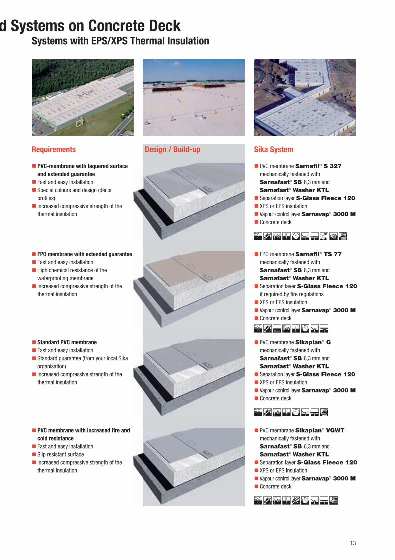
Requirements Sika SystemDesign / Build-up
�� Standard PVC membrane
�� Fast and easy installation�� Standard guarantee (from your local Sika organisation)�� Increased compressive strength of the thermal insulation
�� PVC membrane with increased fi re and
cold resistance
�� Fast and easy installation�� Slip resistant surface�� Increased compressive strength of the thermal insulation
�� PVC membrane Sikaplan® G mechanically fastened with Sarnafast® SB 6,3 mm and Sarnafast® Washer KTL�� Separation layer S-Glass Fleece 120�� XPS or EPS insulation�� Vapour control layer Sarnavap® 3000 M�� Concrete deck
�� PVC membrane Sikaplan® VGWT mechanically fastened with Sarnafast® SB 6,3 mm and Sarnafast® Washer KTL�� Separation layer S-Glass Fleece 120�� XPS or EPS insulation�� Vapour control layer Sarnavap® 3000 M�� Concrete deck
�� PVC-membrane with laquered surface
and extended guarantee
�� Fast and easy installation�� Special colours and design (décor profi les)�� Increased compressive strength of the thermal insulation
�� PVC membrane Sarnafi l® S 327 mechanically fastened with Sarnafast® SB 6,3 mm and Sarnafast® Washer KTL�� Separation layer S-Glass Fleece 120�� XPS or EPS insulation�� Vapour control layer Sarnavap® 3000 M�� Concrete deck
�� FPO membrane with extended guarantee
�� Fast and easy installation�� High chemical resistance of the waterproofi ng membrane�� Increased compressive strength of the thermal insulation
�� FPO membrane Sarnafi l® TS 77 mechanically fastened with Sarnafast® SB 6,3 mm and Sarnafast® Washer KTL�� Separation layer S-Glass Fleece 120 if required by fi re regulations�� XPS or EPS insulation�� Vapour control layer Sarnavap® 3000 M�� Concrete deck
d Systems on Concrete DeckSystems with EPS/XPS Thermal Insulation
Bitumen

14
Requirements Sika SystemDesign / Build-up
�� Standard PVC membrane
�� Fast and easy installation�� Standard guarantee (from your local Sika organisation)
�� PVC membrane Sikaplan® G mechanically fastened to the substrate with Sarnafast® SB 6,3 mm and Sarnafast® Washer IF/IG-C�� Separation layer S-Felt T 300�� Existing build-up on concrete deck
�� PVC membrane with increased fi re and
cold resistance
�� Fast and easy installation�� Standard guarantee (from your local Sika organisation)
�� PVC membrane Sikaplan® VGWT mechanically fastened to the substrate with Sarnafast® SB 6,3 mm and Sarnafast® Washer IF/IG-C�� Separation layer S-Felt T 300�� Existing build-up on concrete deck
�� PVC-membrane with laquered surface
and extended guarantee
�� Fast and easy installation�� Special colours and design (metal roof imitation, décor profi les)
�� PVC membrane Sarnafi l® S327 mechanically attached to substrate with Sarnafast® SB 6,3 mm and Sarnafast® Washer IF/IG-C�� Separation layer S-Felt T 300�� Existing build-up on concrete deck
�� FPO membrane with extended guarantee
�� Fast and easy installation�� Highly chemically resistant waterproofi ng layer
�� FPO membrane Sarnafi l® TS 77 mechanically fastened to the substrate with Sarnafast® SB 6,3 mm and Sarnafast® Washer IF/IG-C�� Existing build-up on concrete deck
Bitumen
Sika Solutions for Refurbishment of Bitumen Roofs with Mechanically Fastened Systems without Additional Insulation

15
Requirements Sika SystemDesign / Build-up
�� Standard PVC membrane
�� Additional thermal insulation�� Standard guarantee (from your local Sika organisation)
�� PVC membrane Sikaplan® G mechanically fastened to the substrate with Sarnafast® SB 6,3 mm and Sarnafast® Washer KTL�� Separation layer S-Glass Fleece 120 (with EPS/XPS insulation)�� New thermal insulation�� Existing build-up on concrete deck
�� PVC membrane with increased fi re and
cold resistance
�� Additional thermal insulation�� Standard guarantee (from your local Sika organisation)
�� PVC membrane Sikaplan® VGWT mechanically fastened to the substrate with Sarnafast® SB 6,3 mm and Sarnafast® Washer KTL�� Separation layer S-Glass Fleece 120 (with EPS/XPS insulation)�� New thermal insulation�� Existing build-up on concrete deck
�� PVC-membrane with laquered surface
and extended guarantee
�� Additional thermal insulation�� Special colours and design (metal roof imitation, décor profi les)
�� PVC membrane Sarnafi l® S327 mechanically fastened to the substrate with Sarnafast® SB 6,3 mm and Sarnafast® Washer KTL�� Separation layer S-Glass Fleece 120 (with EPS/XPS insulation)�� New thermal insulation�� Existing build-up on concrete deck
�� FPO membrane with extended guarantee
�� Additional thermal insulation�� Highly chemically resistant waterproofi ng layer
�� FPO membrane Sarnafi l® TS 77 mechanically fastened to the substrate with Sarnafast® SB 6,3 mm and Sarnafast® Washer KTL�� New thermal insulation�� Existing build-up on concrete deck
Bitumen
Mechanically Fastened Roofi ng SystemsMechanically Fastened Systems with Additional Insulation

16
FPO/TPO Roofi ng Membranes
Type
FPO/TPO (fl exible/thermoplastic polyolefi n) membranes
Brand names
Sarnafi l® T, Sikaplan® T
Advantages
�� High chemical resistance�� Suitable for direct application on bitumen and both EPS and XPS insulation (polystyrenes)�� Systems for exposed roofi ng applications with high fi re ratings / extended fi re resistance�� High tensile strength from embedded polyester reinforcement�� Long life expectancy�� Easy to repair�� Homogeneous hot air welded joints�� Easy to handle on site�� Suitable for use and exposure in different climatic conditions�� Fast installation non-dependent on the weather�� Flame free installation�� Recyclable�� Proven track record for over 20 years
PVC Roofi ng Membranes
Type
PVC (poly vinyl chloride) membranes
Brand names
Sarnafi l®, Sikaplan®, Sika-Trocal®
Advantages
�� Established technology with the longest track record�� Availability of products for exposed roofi ng applications with high fi re ratings / extended fi re resistance�� High tensile strength from embedded polyester reinforcement�� Easy to repair�� Homogeneous hot air welded joints�� Easy to handle on site�� Suitable for use and exposure in all different climatic conditions�� Fast installation almost non-dependent on the weather�� Good vapour permeability�� Highly fl exible�� Flame free installation�� Recyclable�� Proven track record for over 50 years
Sika as Global Leader in Single Ply Membranes

17
Sika products
�� All Sika polymeric roofi ng membranes��Sarnatherm® or Sikatherm® PIR insulation boards��Sarnavap® – vapour control layers��Sarnafast® fasteners and washers (hardened carbon steel or stainless steel)
Sika products
�� All Sika polymeric roofi ng membranes��Sarnatherm® or Sikatherm® PIR insulation boards��Sarnavap® – vapour control layers��Sarnafast® fasteners and washers (hardened carbon steel or stainless steel)
Spot fastening system
The spot or in-lap fastening system provides speed, security and economy of installation on roofs with regular fi xing centres on profi led steel decks. Ideal for projects with the following criteria:�� Locations subject to high winds�� Large roof areas�� Fastrack installation requirements�� Linear fastening and adhered systems are impractical
Linear fastening system
The Sarnabar® linear fastening system features fastening profi les which are attached at right angles to the direction of the membrane. This versatile system is ideal for use when fi xing points are dictated by existing timber joists, channels or reinforce-ment, plus for use on concrete roofs where the in-lap fastening system is less practical. Ideal for projects with the following criteria:�� Locations subject to very high winds�� Concrete decks�� Irregular or bespoke designs�� Spot fastening or adhered systems are impractical
Regular grid fastening system
The regular grid fastening system is ideally suited for attachment to structural metal roof decks (using their grid pattern), as well as when re-roofi ng metal buildings (using existing purlins). This system distributes the wind-uplift load in an even load pattern rather than concentrating it along single rows. Ideal for projects with the following criteria:�� Reduced point loading on the steel deck�� Orientation of the roofi ng membrane is not an issue�� Reduced membrane sheet fl uttering caused by wind-uplift
Designing a Mechanically Fastened Roof –
Expertise from Sika
Sika products
�� All Sika polymeric roofi ng membranes��Sarnatherm® or Sikatherm® PIR insulation boards��Sarnavap® – vapour control layers��Sarnabar® fastening profi les (hot dipped galvanized steel)��Sarnafast® fasteners and insulation washers (hardened carbon steel or stainless steel)
The Right Solution is Selected According to Your Project Requirements:

18
Induction Welding
How does it Work?
This innovative fastening system relies on electromagnetic induction welding to eliminate any fastener penetrations through polymeric roof waterproofi ng membranes – both FPO and TPO. Special coated metal plates are fastened through the roof assembly into the deck and later heat-welded to the underside of the membrane by using an induction welding tool. The plates are fastened in a regular pattern into the roofi ng deck before laying the membrane. This allows easy location of the plates after unrolling the membrane, and ensures even load distribution after the induction welding is completed.
Wind-uplift testing – Spot fastening Wind-uplift testing – Induction welding
System Components
�� Induction welding tool from approved suppliers�� Coated metal plates for FPO and TPO membranes�� Range of fi xings tubes and fasteners for different substrates
Advantages:
�� Quick and easy to install �� No membrane fastener penetrations �� Even wind load distribution�� Enhanced wind-uplift resistance �� Reduced membrane ‘fl utter’ �� Elimination of half sheets in perimeter and corner areas
RhinoBond® OMG-USA
Centrix® Afast – Europe
Sika® – Japan
Coated metal plates
Induction Welding – World Wide

19
Roof System Build-ups with Sika Products
Spot - / In-lap fastening Linear-fastening system
Main component / function
Roof waterproofi ng
membrane
Loose-laidMechanically fastened
Loose-laidMechanically fastened
Fire protection layer or separation layer (where required)
S-Glass Fleece 120 g/m2 S-Glass Fleece 120 g/m2
Thermal insulation Sikatherm® Sarnatherm® Mechanically fastened
Sikatherm® Sarnatherm® Mechanically fastened
Vapour control layer Sarnavap® 500E Sarnavap® 1000E Sarnavap® 2000E Sarnavap® 3000M Sarnavap® 5000SA
Sarnavap® 500E Sarnavap® 1000E Sarnavap® 2000E Sarnavap® 3000M Sarnavap® 5000SA
Levelling layer (where required)
S-Felt A 300 g/m2
S-Felt M 500 g/m2
S-Felt S 800 g/m2
S-Felt A 300 g/m2
S-Felt M 500 g/m2
S-Felt S 800 g/m2
Roof deck Concrete, steel or timber Concrete, steel or timber

20
Installing Mechanically Fastened Roofs
Substrate Quality
In mechanically fastened roofs, the wind loads acting on the membrane are transmitted through the fastening system into the substrate.
The following basic rules are therefore crucial:�� Wind load resistance is directly dependent on the quality of substrate and the permanent anchoring of the fasteners�� The substrate quality must be suffi cient to resist all the wind uplift forces�� Wind-uplift determined from project specifi c wind load calculations
Substrate Preparation
No special additional measures are required.
Membrane
The membrane must be loose-laid and mechanically fastened according to the installation guidelines provided by Sika.
�� The number of fasteners per square metre needs to be determined on each specifi c project�� Sika provides project specifi c wind load calculations according to the relevant National or International Standards�� On metal decks the membranes must be attached at right angles to the direction of the metal ribs�� The overlaps for spot-fastening must be at least 120 mm whereas for linear fastening a minimum of 80 mm is required
Thermal Insulation
The thermal insulation is also mechanically fastened to the roof deck. The number of insulation fasteners needs to be in accordance with local standards or the suppliers specifi cations.
The main insulation technologies are:�� PIR/PUR offering excellent thermal characteristics�� Mineral wool, which can be considered as a non-combustible material�� EPS is the most cost effective solution�� XPS provides very high compressive strength
1 2 3 4
5
10
2 6 7 8 9
0787_S07
17973_S07
T-Joints and Cross Joints Perimeter Flashing
1 Laminated metal sheet 2 Hot-air weld 3 Sealing tape 4 Roofi ng membrane, adhered 5 Sarnabar® with welding cord 6 Roofi ng membrane, mechanically fastened 7 Separation layer / fi re protection layer
(where required) 8 Thermal insulation 9 Sarnavap® vapour control layer10 Sarnavap® jointing tape
Cross joints are to be avoided.By properly laying out the roofi ng membranes, all junctions can be limited to straight welding seams and T-joints (transverse joints).

21
Welding
The seams of Sikaplan® and Sarnafi l® membranes are always hot-air welded. To ensure optimum seam quality, the following actions are required:
�� Always conduct test welds under matching external weather conditions, before starting the works�� The weld areas must be clean and dry, wash with clean water or use an appropriate cleaner if necessary�� Mechanically check all of the seams, to ensure the integrity and completeness of the weld
Securing the Perimeter
The entire perimeter must be secured by the use of a Sarnabar® fastening profi le and a welding cord to absorb the horizontal forces (or spot-fastening as an alternative):
�� Around the entire roof edge�� At all upstands�� At all terminations�� Around all roof penetrations
If it’s not possible to drive fasteners along the perimeter edge into the roof deck, the perimeter must be fastened into the base of the upstands using a Sarnabar® and a welding cord in accordance with local standards or the fi xing suppliers specifi cations.
Maintenance and Inspection
Regular maintenance of the roof saves costs in the long run and helps keep the building in prime condition. Periodic inspections should also be conducted by qualifi ed personnel for the owner; any damage repairs should only by carried out by Sika trained roofi ng professionals. These periodic inspections should include:
�� Inspection of the roof from below and internally�� Physical inspection of the roof surface�� Checking of all connections and fl ashings�� Checking of all drainage systems, in addition to their normal cleaning and maintenance�� Checking the integrity of the lightning protection system
Manual Hot-Air Welding
�� Handheld welding machine�� Suitable for smaller, complicated roofs�� Used for detailing work
Automatic Hot-Air Welding
�� Technically advanced automatic hot-air welding machine�� Effi cient and safe welding�� Reliable, high quality seams�� Suitable for large roof areas

22
Prefabricated Pieces
Sikaplan® and Sarnafi l® prefabricated connection pieces are produced from polyvinylchloride (PVC) or polyolefi n (FPO) and are designed exclusively as integral components of the Sika Roofi ng system:
�� Easy and rapid installation�� Neat and reliable details�� Good resistance to weathering, UV-radiation and stress cracking�� Guaranteed system compatibility�� Secure welding to Sika roofi ng membranes
Vapour Control Layers
Vapour control layers are integral components of Sika Roofi ng systems, allowing airtight, vapour-controlled seals at joints and terminations. The Sarnavap® vapour control layers are based on polyethylene or polymer bitumen, with aluminium facings and are available in a range of sizes and types.
�� Range of diffusion resistance (μ = 3’000’000 to 600’000)
Alternative vapour control and separating
layers:
��Sarnavap® 3000M has a foam backing for installations over rough substrates��Sarnavap® 5000E SA is a self-adhesive vapour barrier made from polymer bitumen with an aluminium foil facing
These vapour control layers come in rolls and all have the following properties:
�� Remain fl exible at low temperatures�� Resistant to chemicals�� Long life-span�� Non-decaying�� Constant vapour diffusion resistance
Thermal Insulation
Sika roofi ng systems also incorporate the most effi cient types of thermal insulation available on the market and include materials suitable for all types of mechanically fastened roofi ng applications including:
PIR/PUR
Thermal insulation boards produced from rigid PU foam with an isocyanurate catalyst. This is a universal and effi cient solution and is the most suitable insulation type for mechanically fastened systems used in the following Sika systems:
��SarnaTherm® PIR��Sikatherm®
��Sarnapur®
EPS
Thermal insulation boards produced from rigid PU foam with an isocyanurate catalyst. This is a universal and effi cient solution and is the most suitable insulation type for mechanically fastened systems used in the following Sika systems:
��SarnaTherm® EPS��S-Therm EPS
Ancillary Materials and Accessories

23
Project Case Study:
Project TD Garden, Boston USA
This multi-purpose arena is home to two of the main professional sports teams in Boston – basketball’s Boston Celtics and ice hockey’s cur-rent champions, the Boston Bruins. This award winning facility hosts more than 200 major entertainment events throughout the year and the roof upgrading and refurbishment was completed with a Sika solution that combined a mechanically fastened, polymeric roofi ng membrane, in combination with a liquid applied membrane (LAM) system – A tailor-made and fully compatible solution using two proven Sika systems.
Sika solutions
Sika-PVC mechanically fi xed roofi ng system:Sarnafi l® S 327-18EL mechanically fastened membrane in traffi c white for the main barrel roof and in lead grey for the lower sloped roof areas, fastened with the RhinoBond® induction welding system (see details page 18).
Sika-liquid applied (LAM) roofi ng system:
The wide gutters and lower edge sections of the barrel roof (up to the snow guards) completed with liquid applied – Sikalastic® 621 LAM membrane system.
Project participants:
Owner: Delaware North Company, Buffalo, NYArchitect: Stephen J. Wessling ArchitectsMain contractor: Shawmut Design & ConstructionSpecialist roofi ng contractor: Greenwood Industries
Combined Roofi ng Systems – Mechanically
Fastened Roof and Liquid Applied Membrane

24
Standards and Approvals
What is FM Global?
Practical ExperienceWhat can Sika Provide with FM Approval?
How to Acquire a Project Based on FM Global
Requirements?
FM Global is an American based insurance company with business and offi ces worldwide, which specializes in loss prevention services and primarily to larger corporations throughout the world, in the Highly Protected Risk (HPR) property insurance market. Since 1999 “FM Global” has been the business and trading name of the “Factory Mutual Insurance Company”.Their business model determines insurance risk and premiums by engineering analysis as opposed to historically based actuarial calculations. This business approach is centred on the belief that property losses can be prevented or mitigated. FM Global engineering personnel regularly visit insured locations to evaluate hazards and recommend improvements to property or work practices, in order to reduce personnel and fi nancial risks if a loss occurs.As part of this strategy FM Global’s engineering team has developed testing procedures to defi ne performance levels and minimum requirements that products and systems must meet. This includes materials for roofi ng systems, where performance in fi re, hail and wind uplift are tested and measured. All testing is performed at FM Approvals Laboratories in the USA.
The FM approval defi nes the complete roofi ng package which includes:�� Steel deck�� Vapour control layer – if required�� Insulation including fi xings�� Separation layer – if required�� Membrane including the fastening system
All approved build-ups and combinations are listed and these can be accessed via FM Approvals complimentary online support tool – www.RoofNav.com at:https://roofnav.fmglobal.com/RoofNav/Login.aspxThe use of any different types of insulation or fastenings is not possible – without additional FM Approvals testing and approval.
Sika holds a number of approvals for mechanically fastened roofi ng systems which meet the different FM requirements, including:��Sarnafi l® TS 77-12E, 15E, 18E, 20E��Sarnafi l® S 327-12EL, 15EL, 18EL��Sikaplan® 12G, 15G, 18G, 20G��Sikaplan® 12VG, 15VG, 18VG, 20VG
�� The building owner is insured by FM Global and uses the FM Global Engineering Services. Sika agrees to support this project baseed on the feedback of the FM Engineer:
– Roof Slope: The FM Engineer will specify based on FM Global Data Sheets
– Wind pressure and Classifi cation: The FM Engineer will specify based on FM Global Data Sheets (for Europe the minimum classifi cation is FM 1-60)
– Internal Fire: The FM Engineers recommend a Class 1 roof, as this gives the highest fl exibility. If Class 1 is provided and no other combustible materials are involved, then sprinklers may not be needed.
– External Fire: The FM Engineer will specify based on FM Global Data Sheets
– Hail: The FM Engineer will specify based on FM Global Data Sheets.
�� The Building Owner’s decide that they want to follow the Highly Protected Risk Guidelines from FM Global and therefore to follow FM Global Data Sheets requirements:
– Sika then supports this project and helps to engineer the roof system and build-up according to these FM Global Data Sheets.

25
What is EOTA? What can Sika Provide from EOTA?
What is an ETA?
EOTA is the European Organisation for Technical Approvals that comprises the Approval Bodies nominated to issue European Technical Approvals (ETA’s) by EU Member States and EFTA States who have contracted into the European Economic Area Agreement. A construction product with an ETA, which means that it satisfi es the relevant Attestation of Conformity provisions, can carry CE marking (Certifi ed European product) and can therefore be placed on the market in any EEA country.
The role of EOTA is primarily to monitor and progress the drafting of ETA Guidelines (ETAG’s) and to co-ordinate all activities relating to the issuing of ETA’s.
Sika holds ETA 006 for our mechanically fastened roofi ng systems and specifi cally includes the following products and systems:
a) From Sika’s FPO product family: Sarnafi l® systemsSarnafi l® TS 77-12 up to Sarnafi l® TS 77-25Sarnafi l® TS 77-12E up to Sarnafi l® TS 77-20E
b) From Sika’s PVC product family: Sarnafi l® systemsSarnafi l® S 327-12 up to Sarnafi l® S 327-24 Sarnafi l® S 327-12EL up to Sarnafi l S 327-20EL
Sikaplan® systemsSikaplan® 12G up to Sikaplan® 20GSikaplan® 12VG up to Sikaplan® 18VGSikaplan® 12VGWT up to Sikaplan® 15VGWT
A European Technical Approval (ETA) is used when there is no relevant Harmonised European Standards for construction products, following a favourable technical assessment by an Approved testing Institute of its fi tness for an intended use.
In conjunction with an Attestation of Conformity procedure (which is intended to ensure that the product specifi cation set out in an ETA is maintained by the manufacturer), ETA’s allow manufacturers to place CE marking on their products. When a European Technical Approval has been issued it is valid in all EEA countries, for a period of fi ve years, and is renewable thereafter.

26
Sika Services and Support in Roofi ng
Jet Stream Wind Load
Calculations
The Sika “Jet Stream” software was developed to support the design of optimized mechanically fastened roofi ng systems for Building Owners, their Designers and Contractors. This ‘state of the art’ software includes the latest European Code and FM Approvals requirements, which cover most National standards and regulations. It is an extremely effi cient and practical tool for producing the most effi cient design and fi xing solutions, including a detailed roof membrane layout and Method Statements, plus all of the necessary information for Sika trained Specialist Contractors to provide estimates, tender and actually carry out the works on site. This tool can also contribute to signifi cant savings in the roof build-up and your overall construction costs.
Features and Benefi ts:
�� A complete system design, consisting of the roof build-up, waterproofi ng membranes and fasteners with wind load calculations in accordance with the relevant standards.�� The roof is optimized to your requirements.�� Applications are worldwide; a unique system that eases communication.�� Calculations available with all of our approved fastening systems and fi xing suppliers.�� Membrane layout drawings give a clear advice on the most effi cient method of installing the membranes and fasteners.�� Includes calculations of the quantities of membrane rolls, fastenings, fi xings and cover strips, saving you time and money in planning and tendering.�� The output is available in almost any language.
Sika is a proven and reliable partner to the whole of the building and construction industry. Worldwide we provide our customers with
far more than just the best ‘state of the art’ and technically proven roof waterproofi ng systems. We also strive to assist and add value
for our customers, by providing much more support and services for our products and their installation.
Technical and Product
Application TrainingThe many different applications for Sika roof waterproofi ng systems obviously can require different installation techniques and detailing solutions. The theoretical, technical and practical application training courses run by Sika’s roofi ng engineers also help to ensure the security and durability of your installation.
Mechanical fastening calculation Code HR
S i k a R o o f i n g S y s t e m s
Project: Musterhaus
Installer: Muster Verlege GmbHNibelungenstr. 1510015 Musterhofen
Building: 07Sep0011MusterhausRoofarea 5728m²Sarnafil TS 77 TS77Sarnafast KT-82x40+SF-4.8
Roof construction
ROOF BUILD-UP Material Manufacturer Type Thickn./Weight
trapezoidal profile galv. steel n.s. E 106vapour barriere PE-foil Sika-Trocal DS-PEthermal insulation PS n.s. PX 20 SEseparating layer glass fibre n.s. n.s. 0waterproofing high polymer Sika AG Sikaplan 15G
Page 2
Musterh
Muster VNibelun10015 M
07Sep00MusterhRoofareSarnafil Sarnafas
tion
UP M
file ge Pion Per g
h
Mechanical fastening calculation Code HR EMA07Sep0011
INTERN
Project: MusterhausTable overviewBuilding: 07Sep0011
MusterhausRoofarea 5728m²Sarnafil TS 77 TS77Sarnafast KT-82x40+SF-4.8
Windload: 1.030 [kN/m²] CPI: 0.30 cpimax: 0.8 S = 1.5Roof Zone Zone Area
[m²]CPE
[-]Wind Suction
[kN/m²]Wind Force
[kN]
Corner (F) 212.74 2.08 3.67 780.34Perimeter (G) 1'005.87 1.68 3.05 3'068.22Field (H) 3'987.89 0.90 1.85 7'390.96Field (I) 521.44 0.60 1.39 724.80
Total 5'727.94 - 2.09 11'964.31
Membrane Sarnafil TS 77 TS77 1.5 fd = 0.93Roof Zone Membrane Width
[m]Membrane Area
[m²]
Corner (F)Perimeter (G)Field (H)Field (I)
Total
Strips 6'704.46 m
Fastener Sarnafast KT-82x40+SF-4.8, Amin: 120 [mm]Roof Zone Fastener Density
[pcs/m²]Distance (horiz./vert.)
Corner (F) 6.38 0.00Perimeter (G) 4.26 0.00Field (H) 4.26 0.00Field (I) 2.13 00
Total 4.07 -5.00 [pcs/m]Perimeter 20.00
Substrate Material Manufacturer Type Thickness/Weighttrapezoidal profile galv. steel n.s. E 106 0.75 mmvapour barriere PE-foil Sika-Trocal DS-PE 0.25 mmthermal insulation PS n.s. PX 20 SE 120 mmseparating layer glass fibre n.s. n.s. 0.25 mmwaterproofing high polymer Sika AG Sikaplan 15G 1.5 mm
Page 12
Project: Musterhaus
Building: 07Sep0011MusterhausRoofarea 5728m²Sarnafil TS 77 TS77Sarnafast KT-82x40+SF-4.8
PI: 0.30 cpimax: 0.8 S = 1.5CPE
[-]Wind Suction
[kN/m²]Wind Force
[kN]
2.08 3.67 780.341.68 3.05 3'068.220.90 1.85 7'390.960.60 1.39 724.80
- 2.09 11'964.31
fd = 0.93mbrane Width
[m]Membrane Area
[m²]
Amin: 120 [mm]y Distance (horiz./vert.)
0.000.000.00
00-
20.00
Manufacturer Type Thickness/Weightn.s. E 106 0.75 mmSika-Trocal DS-PE 0.25 mmn.s. PX 20 SE 120 mmn.s. n.s. 0.25 mmSika AG Sikaplan 15G 1.5 mm
Page 12
Mechanical fastening calculation Code HR EMA07Sep0011
Installation in area: F 1 Project: MusterhausBuilding: 07Sep0011, Musterhaus, Roofarea 5728m², Sarnafil TS 77
TS77, Sarnafast KT-82x40+SF-4.8
Laying DirectionProfile's direction
Perimeter fasteners*Seamfastening, Intermediate Fastening
Roof PlanOverlap [mm]
70 40 10
*) Perimeter fasteners:
Continuous
d [mm] = 200
Roof ZonesFastening distances
Corner (F)
Perimeter (G)
Field (H)
106
250
Fastening in area: F 1, G Intermediate fasteningMembrane width [m] Centres of fastener rows
[mm]Fastening schemesRoof zone
Corner (F) 2.00 627 1 - 11 - 1Perimeter (G) 2.00 940
Where a high uplift zone exists next to a lower rated one, the first row of fasteners that falls outside of the calculated width, and runs parallel to the edge of that zone, must be installed at the same centres as those falling inside the higher uplift area
Page 5

27
Full Range of CAD Details and
Technical DocumentationA complete range of CAD detail drawings and installation guidelines, Method Statements, Product Data Sheets and considerable additional technical documentations, approvals and certifi cates are available for all Sika roofi ng systems.
Sika Guarantees Sika’s roofi ng guarantees are provided to meet our customer’s needs. These fully comprehensive guarantees for water tightness and compatibility with other building materials are issued individually for each project and in accordance with all relevant local regulations.
Roof Condition Survey and
Assessment for RefurbishmentSika roofi ng engineers can advise and assist with the necessary roof Condition Survey and Diagnostic Assessment required for roof refurbishment. This provides tailor-made roof re-waterproofi ng specifi cations which also include full detailing solutions and Method Statements.
Sika provides extensive support and services for each of our roofi ng product ranges. This is tailored for each system and covers all stages
in the design, planning and execution of Sika roof waterproofi ng systems. This includes everything from defi ning the detailed requirements
analysis for new structures or the roof condition survey and diagnostic assessment for roof refurbishment projects, through full specifi -
cation and tender documentation, to expert technical and practical installation training, plus full support on site – Anywhere in the world.
Product&Windload GuaranteeProduct&Windload Guarantee
Ro
ofi
ng
Sika Services AG, BU Contractors, Industriestrasse, 6060 Sarnen, Switzerland
Tel. +41 58 436 79 66, Fax +41 58 436 76 60, www.sika.com
SPECIM
EN10 years
Applicator
Guarantee No.: 123456789
Building with address: Coca Cola ProductionIndustriestrasse 55CH-6000 Luzern
Size of roof area: Size in m²: 5’000
Guarantee Period: 10 years from the date of issuance
Applicator: Rolling Membranes AGSternmattstrasse 38CH-6020 Emmenbrücke
Delivery Date: 01.01.2007
Delivered membranes Sarna� l TS 77-18Other Sika Products delivered 1
Sika Services AG
Felix Muster Felix MusterFelix Muster 1 Felix Muster 2
8. Mai 2007, SarnenDate / Place
1 membranes and other Sika Products jointly referred to as “Sika Products
Serviices AGG
41 588 436 779
PPPPPPEEEEEE
0 ye
pplic
arantee
ding w
e of roo
arantee
plicator:
EEEEEEEEEEEEEEPPPPPPEEEEEEPPPEEEPPPPPPEEEEEEPPPEEEa ServicPlilix MMMMuusx Must
MMaii 22200e / Plac
Product GuaranteeProduct Guarantee
Ro
ofi
ng
Sika Services AG, BU Contractors, Industriestrasse, 6060 Sarnen, Switzerland
Tel. +41 58 436 79 66, Fax +41 58 436 76 60, www.sika.com
SPECIM
EN10 years
Applicator
Guarantee No.: 123456789
Building with address: Coca Cola ProductionIndustriestrasse 55CH-6000 Luzern
Size of roof area: Size in m²: 5’000
Guarantee Period: 10 years from the date of issuance
Applicator: Rolling Membranes AGSternmattstrasse 38CH-6020 Emmenbrücke
Delivery Date: 01.01.2007
Delivered membranes Sarna� l TS 77-18Other Sika Products delivered 1
Sika Services AG
Felix Muster Felix MusterFelix Muster 1 Felix Muster 2
8. Mai 2007, SarnenDate / Place
1 membranes and other Sika Products jointly referred to as “Sika Products
ka Seervicesss AG, BBU CContractors, Industriestrasse, 6060 Sarnen, Switzerland
. +411 58 433666 79 666, FFax +41 58 436 76 60, www.sika.com
PPPPPPPPPPEEEEEEEEEEEEEEEECCCIM
ENNNNN0 years
Applicator
uarantee No.: 12345678
MMuilding with address: Coca Cola Production
ME
ME
MIndustriestrasse 55
MMMnMMize of roof area: IM5’000IMIMuarantee Period:
CIears from the date of issuanceII
pplicator: CCCRolling Membranes AG
EEEEEEEECCCSternmattstrasse 38
EEEEEEEEEEEEECCCCH-6020 Emmenbrücke
eli EEEEEEEEEEEEEEEEEEEE 01.01.2007
branes
PPPPPPPPPPEEEEEEEEEEEEEEEEPPPPEEEE Sarna� l TS 77-18�roducts delivered PPPPPPPPPPEEEEEEEEEEEEEEEPPPPEEEE 1
ka Services AGPPPPFelixx MMMMuuusssttteerrr r Felix Muster
elix Muster 1 Felix Muster 2
. MMaaii 2200000077,7,, SSarnenate / Place
1 membranes and other Sika Products jointly referred to as “Sika Products
Membrane GuaranteeMembrane Guarantee
Sika Services AG, BU Contractors, Industriestrasse, 6060 Sarnen, Switzerland
Tel. +41 58 436 79 66, Fax +41 58 436 76 60, www.sika.com
Ro
ofi
ng
SPECIM
EN10 years
Applicator
Guarantee No.: 123456789
Building with address: Coca Cola ProductionIndustriestrasse 55CH-6000 Luzern
Size of roof area: Size in m²: 5’000
Guarantee Period: 10 years from the date of issuance
Applicator: Rolling Membranes AGSternmattstrasse 38CH-6020 Emmenbrücke
Delivery Date: 01.01.2007
Delivered membranes Sarna� l TS 77-18Other Sika Products delivered 1
Sika Services AG
Felix Muster Felix MusterFelix Muster 1 Felix Muster 2
8. Mai 2007, SarnenDate / Place
1 membranes and other Sika Products jointly referred to as “Sika Products
1 2 53 6 7 8 9
0793_S07
4
10
17970_S07
1 3 2 4 65 7

28
Sika Roofi ng Systems – Worldwide Project Case Studies
Porsche, Leipzig, Germany
Main requirements:
�� Long lasting roof waterproofi ng�� High aesthetic appearance
Sika solution:
�� Mechanically fastened Sarnafi l® TS 77
Industrial Building, France
Main requirements:
�� Fast and effi cient application�� Lightweight system
Sika solution:
�� Mechanically fastened Sikaplan® 15G
Imax Cinema, Cologne, Germany
Main requirements:
�� High aesthetic appearance�� Complex roof shape
Sika solution:
�� Mechanically fastened Sarnafi l® S 327

29
Miller Park, Milwaukee, USA
Main requirements:
�� High aesthetic appearance�� Complex roof shape
Sika solution:
�� Mechanically fastened Sarnafi l® S 327
Utah Olympic Oval, Kearns, USA
Main requirements:
�� Energy saving�� Customized logo inclusion
Sika solution:
�� Mechanically fastened Sarnafi l® S 327
Walmart Distribution Centre, UK
Main requirements:
�� Fast and effi cient application�� Cost effective solution
Sika solution:
�� Mechanically fastened Sikaplan® 15G

30
Performance and Installation Related Requirements
Bitumen
Slip Resistance
Compatibility to BitumenHigh Fire UV-Resistance
Resistance to Pedestrian
and Light Wheeled Traffi c
Resistance to Cold
Root Resistant
Thermal Shock
Resistance
Fast Installation
The Sika roofi ng product range includes sheet membranes with embossed surfaces to provide slip resistance. Different degrees of slip resistance can be also achieved with Sika liquid applied membranes by broad-casting with selected grades of quartz sand.
As bitumen has been used as a traditional roofi ng material for many years, it is often still present on existing roofs to be refur-bished or upgraded in terms of waterproof-ing, fi re or insulation. For a fast and secure solution bitumen compatibility is a major requirement. Sika provides systems which are bitumen-resistant and can be used in almost any refurbishment situation.
Fire resistance requirements can be very individual and dependent on the type of construction and use of the building. If the roofi ng membrane is the top roof surface, then the membrane material must generally be classifi ed as self-extinguishing. Sika roofi ng materials are all designed to comply with this and all relevant international and local building regulations in terms of fi re.
Light, especially energy-rich ultraviolet light, has an ageing effect on roof membranes that can eventually result in surface cracking and degradation. Sika roofi ng membranes for exposed roofs are all more than suffi ciently UV stabilized against this to perform for the long term, even in extreme climates and locations with high UV light exposure.
Increasingly, roofi ng systems are being used for areas exposed to pedestrian and vehicular traffi c, i.e. on roof terraces or car parking areas. If the roofi ng membrane is the top surface for traffi c, it must withstand this abraison and wear without additional protection. It also has to be slip-resistant and may need different colours for line marking etc. Sika liquid applied membrane systems provide full service traffi cability for pedestrians and / or vehicles as required.
The weather around the world provides different climatic conditions in which roofi ng systems have to perform and resistance to minus temperatures is one of the main requirements here. All membranes from Sika stay fl exible in cold within their stated performance limits. Some Sika roofi ng systems have the advantage that they can be installed at temperatures below zero.
Membranes used under ballast must also withstand penetration from the roots of plants. Roof gardens and other green roofs obviously have a particular requirement for this, not only from the membrane, but also at their welded seams, connections and terminations. Sika single ply and liquid applied membranes for ballasted roof systems all resist root penetration and are treated to be resistant against micro- organisms, or they are inherent by fully resistant.
Sika roof waterproofi ng membranes and all of the ancillary roofi ng products are specially designed to withstand sudden changes of temperature and weather conditions. They will not be damaged by extended or sudden thermal changes in cold, heat, snow, rain, etc.
Installation time is always an important issue and cost factor for roofi ng systems. Sika has developed many special roofi ng systems and ancillary products which allow extremely rapid and cost effective installation.

31
Fully Adhered to the
Substrate
Single Component
Products
Good Vapour Permeability
Wide Colour Range
Easy Application by
Brush or Roller
Loose Laid Build-up
Crack Bridging Ability
Mechanical fastenings
and fi xings
No Penetrations into the
Deck
Partially Adhered to the
Substrate
Highest Aesthetic
Appearance
Seamless Waterproofi ng
Superior aesthetic appearance, regardless of the roof shape, or with no penetration of the roof deck, is often a requirement for both new and refurbishment projects. With Sika fully adhered systems the membrane is fully bonded to the substrate, therefore it can meet these high aesthetic and performance requirements reliably and with low mainte-nance costs.
1-C Sika liquid applied membranes are probably the easiest to install. They are applied ’direct from the can’ and do not require mixing with other components.
Sika has developed membranes which are waterproof, but with excellent vapour diffusion properties. This allows any moisture in the structure below to evaporate.
Sika membranes are supplied in several standard colours, some in an extensive range. Special colours can also be made to order or colour matched to a client’s requirements.
Sika liquid applied membranes can be applied by brush and roller. This application is easy and does not require investment in expensive application equipment.
Loose laying of the fl exible membrane and its ancillary materials is the main method established to build-up a roof deck and waterproofi ng system. It allows free air fl ow to ventilate the thermal insulation and it also helps to compensate for the structure’s movement. The membrane must then be mechanically fastened or ballasted for restraint against wind uplift.
The Sika liquid applied membranes in particular can provide outstanding crack-bridging properties, with high fl exibility and elasticity – even at low temperatures
If the membrane is installed as the top layer of the roof, wind uplift will occur through wind suction and pressure. The membrane must therefore be restrained against wind uplift and the most cost effective method of doing this is by mechanical fastening into the support structure. Sika systems are designed to withstand wind loads using the most effi cient fi xings.
A mechanical fastening system may not be possible due to unacceptable drilling noise for the fi xings, contamination through the deck, or due to the structural design itself. All of these diffi culties and their potential costs can be overcome by using Sika adhered, ballasted or liquid applied membrane systems.
If the membrane is to be used in an exposed situation, but mechanical fi xing is not desirable for technical or other reasons, all layers of the system build-up must be bonded to the substrate below. In Sika partially adhered systems the liquid adhesive is applied on the substrate in beads or strips. This provides fast cost effective installation with low adhesive consumption.
Sometimes roofi ng materials not only have an important waterproofi ng function, but they must also meet high design and architectural requirements. Sika has developed several advanced systems suitable for installation over complex roof shapes with good looking top surfaces, i.e. including smooth surfaces, standing seam metal roof imitation and other special profi les, etc.
The Sika liquid applied membranes provide seamless waterproofi ng over the entire roof surface. In addition to technical advantages, it can also create an excellent visual appearance.

Joint Sealing
Sikafl ex®
Sikasil®
Grouting
Sikadur®
SikaGrout®
Roofi ng
Sarnafi l®
Sikaplan®
SikaRoof® MTC®
Waterproofi ng
Sikaplan®, Sikalastic®
Sika® & Tricosal® Water stopsSika® Injection Systems
Concrete Production
Sika® ViscoCrete®
Sika® Retarder®
Sika® SikaAer®
Flooring
Sikafl oor®
SikaBond®
Concrete Repair and Protection
Sika® MonoTop®
Sikagard®
Sikadur®
Corrosion and Fire Protection
SikaCor®
Sika® Unitherm®
Structural Strengthening
Sika® CarboDur®
SikaWrap®
Sikadur®
Sika Full Range Solutions for Construction
Our most current General Sales Conditions shall apply.Please consult the Product Data Sheet prior to any use and processing.
Sika Services AG
Business Unit ContractorsIndustriestrasse 266060 Sarnen / SwitzerlandPhone +41 58 436 79 66Fax +41 58 436 76 60www.sika.com
Also Available from Sika
© S
ika
Serv
ices
AG
/ BU
Cont
ract
ors
/ Sik
a_M
echa
nica
lly_F
aste
ned_
Roofi
ng_
Syst
ems
/ 03.
2012
/ ID
: 230
58