mechanically jointed rodless cylinder series my1 w · introducing our mechanically jointed rodless...
TRANSCRIPT

Mechanically Jointed Rodless Cylinderwith Protective Cover
Series MY1W ø16, ø20, ø25, ø32, ø40, ø50, ø63
Introducing our mechanically jointed rodless cylinder with a superior dustproof, water-resistant protective cover.
CAT.ES20-161 A

Mechanically Jointed Rodless Cylinderwith Protective Cover
Base cylinder
Cover
Slide tableSlide plate
Seal guide∗
Side seal assembly∗
Spacer∗
Slide plate∗
Items marked with an "∗ " are for Series MY1WK (with side seal) only.
End plate
Belt clamp
Spacer
Port cover
Variations Variations
MY1MWMY1MWKMY1CW
MY1CWK
Series Guide type Cover OptionsBore sizes (mm)
16 20 25 32 40 50 63
Slide bearingWith protective cover
With protective cover+ side seal
With protective cover
With protective cover+ side seal
Cam followerguide
• Centralized piping
• Stroke adjusting unit
• Side support
Features 1

In environments where the cylinder is exposed to dust particles and water spray or splash, its dustproof, water-resistant cover offers superior protection.
Cover units and Side seal units can be installed on the already existing Series MY1M/MY1C.
Side seals provide greater lateral dustproofing and water resistance.
Protective cover only minimally adds to overall length.
Base cylinder + 20 to 30mmBase cylinder
Stroke adjusting unit
Stroke availabilityPiping ports are concentrated on one side.
Side supports
Cylinder and work piece mounting interchan-geability is possible between Series MY1MW and MY1CW.
Interchangeable mounting
Centralized piping
Side supports prevent cylinder tube from sag-ging in long stroke applications.
Strokes can be adjusted either at one end or both ends.• With adjusting bolts• With low load shock absorber + Adjusting bolts (L unit)
Features 2
Strokes may be selected in increments of 1mm.
Water-resistant solid state switches can be mounted onto the ø25 to ø40 models.
Side seal
The cover in no way interferes with the installation of base cylinder options.
Offers excellent dust and water resistance

NilS
Both endsOne end
NilK
Without side sealWith side seal
Number of strokeadjusting units Note)
Note) "S" is available when stroke adjusting units are A and L.
1
How to Order
16202532405063
16mm20mm25mm32mm40mm50mm63mm
Cylinder bore size
NilG
StandardCentralized piping
Piping
MC
Slide bearing guideCam follower guide
Guide type
Side seal Note)
Stroke adjusting unitNilAL
AL
Without adjusting unitWith adjusting bolt
With low load shock absorber + Adjusting boltWith one A unit and one L unit
Shock absorbers part numbers for L unit
NilSn
2 pcs.1pc.
"n" pcs.
Number ofauto switches
Auto switch type
∗ Refer to the table below for auto switch types.
Nil Without auto switch
MY1 M W K
Applicable auto switches:For ø16, ø20
Wiring(output)
Load voltage
DC AC
Auto switch type
Electrical entry direction
Perpendicular In-line
Lead wire length (m)∗
3(L)
0.5(Nil)
5(Z)
IC circuit
Applicableloads
ICcircuit
ICcircuit
ICcircuit
—
—
—
—
RelayPLC
RelayPLC
—
—
—
A90
A93
A96
F9N
F9P
F9B
F9NW
F9PW
F9BW
A90V
A93V
A96V
F9NV
F9PV
F9BV
F9NWV
F9PWV
F9BWV
100V or less
100V
—
—
5V12V
5V12V
5V12V
12V
5V
12V
12V
24V
—
24V2-wire
3-wire(NPN)3-wire(NPN)3-wire(PNP)
2-wire
No
Yes
Yes
—
—
For ø25, ø32, ø40, ø50, ø63Load voltage
DC AC
Note 2)
0.5(Nil)
3(L)
5(Z)
Applicableloads
ICcircuit
ICcircuit
ICcircuit
—
—
RelayPLC
RelayPLC
—
—
Z76
Z73
Z80
Y59A
Y7P
Y59B
Y7NW
Y7PW
Y7BW
—
—
—
—
100V or less
100V
—
—
5V12V
12V
5V
5V12V
12V
24V
—
24V2-wire
3-wire(NPNequiv.)
3-wire(NPN)3-wire(PNP)
2-wire
No
Yes
Yes
—
—
3-wire(NPN)3-wire(PNP)
2-wire
2-wire
5V12V
12V
ICcircuit
—
—
Y69A
Y7PV
Y69B
Y7NWV
Y7PWV
Y7BWV
—
∗ Lead wire length symbols: 0.5m ……...… Nil (Example) Y59A3m .............. L Y59AL5m .............. Z Y59AZ
∗∗ Solid state switches marked "" are produced upon receipt of order.Note 1) Perpendicular electrical entry is not available for ø50 and ø63.Note 2) Water-resistant switches are not available for ø50 and ø63.
3-wire(NPN)3-wire(PNP)
2-wire
Y7BW30025
Mechanically Jointed Rodless Cylinderwith Protective Cover
Series MY1WSlide Bearing Guide Type/Cam Follower Guide Typeø16, ø20, ø25, ø32, ø40, ø50, ø63
Stroke
L unit
20 25 32 40Bore size
(mm)Unit
16 50 63
RB1007 RB1412RB0806 RB2015
With protective cover
Y7BAL
Refer to the standard stroke table on page 2.
Note) Cylinders with side seal are available for ø16 to ø40.
Refer to pages 12 through 20 for detailed auto switch specifications.
∗ Lead wire length symbols: 0.5m ……...… Nil (Example) F9NW3m .............. L F9NWL5m .............. Z F9NWZ
∗∗ Solid state switches marked "" are produced upon receipt of order.
Diagnosticindication2-colordisplay
Diagnosticindication2-colordisplay
Water-resistant2-colordisplay
Grommet
Grommet
Specialfunction
Indic
ator
light
Wiring(output)
Electrical entry
Auto switch typeElectrical entry direction
Perpendicular In-line
Lead wire length (m)∗
Grommet
Grommet
Typ
eR
eed
sw
itch
So
lid s
tate
sw
itch
Specialfunction
Indica
tor lig
ht
Electrical entry
Typ
eR
eed
sw
itch
So
lid s
tate
sw
itch
Note 1)

2
Mechanically Jointed Rodless Cylinder with Protective Cover Series MY1W
16
A
0 to –5.6 0 to –6 0 to –11.5 0 to –12 0 to –16
A L
20
L
25
LA
32
LA
40
LA
50
A
63
L LA
0 to –20 0 to –25
Standard Strokes
Bore sizes(mm)
16
20, 25, 32, 40, 50, 63
100, 200, 300, 400, 500, 600, 700800, 900, 1000, 1200, 1400, 16001800, 2000
3000
16 to 63
100 to 1000mm/s
100 to 1000mm/s Note 1)
100 to 1500mm/s Note 2)
RB0806
2.9
6
80
1.96
4.22
RB1007
5.9
7
70
4.22
6.86
RB1412
19.6
12
45
6.86
15.98
RB2015
58.8
15
25
8.34
20.50
5 to 60
1500
Specifications
16 20 25 32 40 50 63
Air
Double acting
MY1MW: 0.15 to 0.8MPa; MY1CW: 0.1 to 0.8MPa
1.2MPa
5° to 60°C
Air cushion
Non-lube1000 or less +1.8
1001 to 3000 +2.80
02700 or less +1.8 ; 2701 to 5000 +2.8
0
M5 x 0.8
ø4
Rc 1/8
ø6
Rc 1/4
ø8
Rc 3/8
ø11
Symbol
ø10ø5
Bore size (mm)
Fluid
Action
Operating pressure range
Proof pressure
Ambient and fluid temperature
Cushion
Lubrication
Stroke length tolerance
Front/Side ports
Bottom ports(centralized piping type only)
Portsize
Stroke Adjusting Unit Specifications
Bore size (mm)
Configuration andshock absorber
Unit symbol
Fine stroke adjustment range (mm)
Stroke adjustment range
Withadjusting
bolt
RB0806 with
adjustingbolt
Withadjusting
bolt
Withadjusting
bolt
When exceeding the fine stroke adjustment range: Use Made to Order specifications "-X416" and "-X417". (Refer to page 21 for details.)
Shock Absorber Specifications Piston Speed
Withadjusting
bolt
Withadjusting
bolt
Withadjusting
bolt
Withadjusting
bolt
Model
Max. energy absorption (J)
Stroke absorption (mm)
Max. impact speed (mm/s)
Max. operating frequency (cycle/min)
Spring force (N)
Operating temperature range (°C)
Extended
Retracted
Note 1) The air cushion capacity will be reduced when the stroke adjustment range is increased by the adjusting bolt. When exceeding the air cushion stroke ranges shown on page 28, the piston speed should be 100 to 200mm/s.
Note 2) The piston speed is 100 to 1000mm/s for centralized piping.
Note 3) Cylinders should be operated at a speed within the absorption capacity range. Please refer to page 28.
Bore sizes (mm)
Without stroke adjusting unit
A unit
L unit
Stroke adjusting unit
Standard strokes (mm)∗ Max. manufacturable stroke(mm)
∗ Strokes can be manufactured in 1mm increments, up to the maximum stroke. If the required stroke length exceeds 2000mm, please indicate "-XB11" at the end of the ordering number. Refer to the Made to Order specifications on page 21 for details.
0
RB0806 with
adjustingbolt
RB1007with
adjustingbolt
RB1412with
adjustingbolt
RB1412with
adjustingbolt
RB2015with
adjustingbolt
RB2015with
adjustingbolt

3
Options
A unit
L unit
16
MYM-A16A
MYM-A16L
20
MYM-A20A
MYM-A20L
25
MYM-A25A
MYM-A25L
32
MYM-A32A
MYM-A32L
16
MY-S16A
MY-S16B
20
MY-S20A
MY-S20B
25
MY-S25A
MY-S25B
32
MY-S32A
MY-S32B
63
MY-S63A
MY-S63B
MY-S40A
MY-S40B
40
MYM-A40A
MYM-A40L
63
MYM-A63A
MYM-A63L
50
MYM-A50A
MYM-A50L
Bore size(mm) 40 50
Weights
Bore size(mm)
16
20
25
32
40
50
63
1.25
1.90
2.56
4.75
7.79
13.53
21.84
1.25
1.85
2.50
4.62
7.51
13.61
21.94
0.16
0.18
0.28
0.42
0.57
0.82
1.17
0.16
0.19
0.28
0.43
0.61
0.83
1.18
0.01
0.02
0.02
0.04
0.08
0.08
0.17
Basicweight
Basicweight
0.03
0.04
0.07
0.14
0.25
0.36
0.68
0.04
0.05
0.11
0.23
0.34
0.51
0.83
Unit: kg
Theoretical Output
Unit: N
16
20
25
32
40
50
63
40
62
98
161
251
392
623
0.3
60
94
147
241
377
588
934
0.4
80
125
196
322
502
784
1246
0.5
100
157
245
402
628
981
1557
0.6
120
188
294
483
754
1177
1869
140
219
343
563
879
1373
2180
160
251
392
643
1005
1569
2492
Operating pressure (MPa)Bore size(mm)
Piston area(mm²)
200
314
490
804
1256
1962
3115
MY1MW MY1CW
0.2 0.7 0.8
Series MY1W
Additionalweight per 50mm
of stroke
Side supportweight (per set)
Stroke adjusting unit weight(per unit)
Type A and B A unit L unitAdditional
weight per 50mmof stroke
Calculation method –– Example: MY1MW25-300ABasic weight ……………………………… 2.56kg
Additional weight ………………………… 0.28kg per 50mm of stroke
Weight of A unit ………………………….. 0.07kg
Cylinder stroke …………………………… 300mm
2.56 + 0.28 x 300 ÷ 50 + 0.07 x 2 = Approx. 4.38kg
Bore size(mm)
Unit type
Stroke adjusting unit model numbers
Side support A
Side support B
Side support model numbers
Refer to page 9 for detailed information on dimensions.
Type

4
Construction
MY1W
MY1WK with side seal
No.12345678910112122232425
Slide tableCoverEnd plateBelt clampSlide platePort coverSpacerHexagon socket button head screwHexagon socket head cap screwHexagon socket button head screw
Seal guide ASeal guide BSlide plateSpacerHexagon socket head cap screw
Description MaterialAluminum alloyAluminum alloyAluminum alloySpecial resinSpecial resinSpecial resin
Stainless steelChromium molybdenum steelChromium molybdenum steelChromium molybdenum steel
—Special resinSpecial resinSpecial resin
Stainless steelChromium molybdenum steel
NoteHard anodizedHard anodizedHard anodized
(ø25 to ø40)(ø25 to ø40)Nickel platedNickel platedNickel platedMY1M/MY1C
Nickel plated
ø16
MYMW-16-stroke
—
MYMK-16-A
ø20
MYMW-20-stroke
—
MYMK-16-A
ø25
MYMW-25-stroke
—
MYMK-25-A
ø32
MYMW-32-stroke
—
MYMK-25-A
ø40
MYMW-40-stroke
—
MYMK-25-A
ø50
MYMW-50-stroke
—
—
ø63
MYMW-63-stroke
—
—
Parts list
No.121314151617181920
Seal beltDust seal bandScraperPiston sealCushion sealTube gasketO-ringO-ringSide seal assembly
Description MaterialSpecial resin
Stainless steelNBRNBRNBRNBRNBRNBR
Polyurethane
Qty.112222242
ø16MY16-16A-StrokeMY16-16B-StrokeMYM16-15AK0500
GMY16MYB16-15-A7163
P12ø4 x ø1.8 x ø1.1ø7 x ø4 x ø1.5
MYMK-16-stroke
Seal listø20
MY20-16A-StrokeMY20-16B-StrokeMYM20-15AK0501
GMY20MYB20-15-A7164
P16ø5.1 x ø3 x ø1.05
ø7 x ø4 x ø1.5MYMK-20-stroke
ø25MY25-16A-StrokeMY25-16B-StrokeMYM25-15AA5903
GMY25RCS-8TMY-25
ø7.15 x ø3.75 x ø1.7C-6
MYMK-25-stroke
ø32MY32-16A-StrokeMY32-16B-StrokeMYM32-15AA5904
GMY32RCS-10TMY-32
ø8.3 x ø4.5 x ø1.9C-7
MYMK-32-stroke
ø63MY63-16A-StrokeMY63-16B-StrokeMYM63-15AK0503
GMY63MC-20
P53C-4C-14
—
ø50MY50-16A-StrokeMY50-16B-StrokeMYM50-15AK0502
GMY50MC-16
P44C-4
C-11.2—
ø40MY40-16A-StrokeMY40-16B-StrokeMYM40-15AA5905
GMY40RCS-12TMY-40
C-4C-9
MYMK-40-stroke
Rodless cylinder
Coverunit
Sidesealunit
Mechanically Jointed Rodless Cylinder with Protective Cover Series MY1W
Note) Two types of dust seal band are available. Verify which type to use for ordering since the part number differs depending on the treatment of the hexagon socket head set screw. (A) Black zinc chromated → MY-16B-stroke (B) Nickel plated → MY-16BW-stroke

5
Dimensions: ø16, ø20
4-MM with depth M4-øB counterbore with depth C
øLD through hole bottom side J with depth K
2 x 2-M5 x 0.8(Hexagon socket head plug)
2-M5 x 0.8(Hexagon socket head plug)
2-M5 x 0.8(Hexagon socket head plug)
This port is not available for use.
M5 x 0.8 (Port)
M5 x 0.8(Hexagon socket head plug)
2-ø4
Bottom port(Applicable O-ring)
M5 x 0.8(Port)
M5 x 0.8(Hexagon socket head plug)
M5 x 0.8(Port)
M5 x 0.8(Hexagon
socket head plug)
PA
L(LL)
PG
PB
Q + Stroke
QW
LW
Z + Stroke
10A
CH
NE
W
NW
LH
H
RRS
S
TTUU
RRS
S
TT UU
VVVV
XX
XX
N
GBG
GB
NC
WX
ø8.4
1.1
PP
YW
S
Y
NH
(WW
)
(WW)
GB
G
PP
Centralized pipingCentralized piping
Bore size (mm)1620
A090110
B6.07.5
C3.54.5
G13.512.5
GA8.5—
GB16.220.0
H5258
K1012
L110130
LD3.64.8
LH3839
LL3545
LW8488
M6.07.5
N2025
NC1417
NE49.555.5
NH16.521.7
NW5660
CH2526
JM5 x 0.8M6 x 1
MMM4 x 0.7M5 x 0.8
Bore size (mm)1620
PA4050
PB 94100
PG3.54.5
Q153191
QQ 910
QW4845
RR11.014.5
TT1518
UU1412
VV10.012.5
W102110
WW1314
YW5458
Z180220
PP07.511.5
SS2.55.5
Bore size (mm)1620
WX3032
Y6.58
S9 6.5
Applicable O-ringC6C6
Hole sizes for centralized piping on the bottom
Series MY1W
(Mounting side should be machined to these dimensions.)
M5 x 0.8(Hexagon
socket head plug)
M5 x 0.8(Port)

6
Dimensions: ø25, ø32, ø40
2-ZZ(Hexagon socket head taper plug)
2-ZZ(Hexagon socket head taper plug)
P (Port)
Cushion needle
2-P(Hexagon sockethead taper plug)
P(Hexagon socket head taper plug)
P(Port)
P(Hexagon socket head taper plug)
2-P(Hexagon socket head taper plug)
4-øB counterbore with depth CøLD through hole bottom side J with depth K
4-MM with depth M
Bottom port (ZZ)(Applicable O-ring)
2-ød
Back port(Refer topage 39.)Back port
(Refer to page 39.)
P(Port)P
(Port)
P(Hexagon sockethead taper plug)
A
Z + Stroke
10
NH
CH
W
LH
H
XX
VV
XX
VV
G
GB
N
NC
RR2
SS
TTUU PP1
PP2
TT UU
RR1
SS
MW
Q + StrokePG
QW
PA
PB
L(LL)
LW
NE
WX
ø11.4
1.1S
Y
NW
YW
WW
WW
Centralized piping
Centralized piping
Mechanically Jointed Rodless Cylinder with Protective Cover Series MY1W
Bore size (mm)253240
A120150180
B091114
C5.56.58.5
G171923
GB24.530.036.5
H668298
K09.516.015.0
L142172202
LD5.66.88.6
LH38.744.247.2
LL496479
LW100122138
M101313
N303745
NC212632
NE648096
NH283748
NW607494
MW668096
CH25.731.534.8
JM6 x 1M8 x 1.25M10 x 1.5
MMM5 x 0.8M6 x 1M6 x 1
Bore size (mm)253240
PA 60 80100
PB112134150
PG789
Q206264322
QQ161626
QW466072
RR217.924.0
29 .0
RR118.922.0
25.50
TT15.521.026.0
UU161621
VV161923
W122144160
WW111320
YW070088104
Z240300360
PP112.715.517.5
PP212.718.520
SS5.14.09.0
Bore size (mm)253240
WX384854
Y91114
S469
d668
D11.411.413.4
Applicable O-ringC9C9
C11.2
Hole sizes for centralized piping on the bottom
(Mounting side should be machined to these dimensions.)
P(Hexagon sockethead taper plug)
PRc 1/8Rc 1/8Rc 1/4

7
Dimensions: ø50, ø63
Centralized pipingCentralized piping
Bore size (mm)5063
A212245
B1719
C10.512.5
G27.029.5
GA25.027.5
GB37.539.5
H124149
K2832
L250290
LD1114
LH5765
LL087100
LW168200
M1516
N4750
NC4460
NE122147
NH6070
CH41.547.0
GC1215
JM14 x 2M16 x 2
MMM8 x 1.25M10 x 1.25
Bore size (mm)5063
PA120140
NW118142
PB186220
PG1012
Q380436
QQ2830
QW090110
RR3549
TT3543
UU2428
VV2830
W200236
WW2225
YW128152
Z424490
PP2642
SS1013
Bore size (mm)5063
WX7492
Y1818
S89
Applicable O-ringC15C15
Hole sizes for centralized piping on the bottom
Series MY1W
(Mounting side should be machined to these dimensions.)
Cushion needle
Rc 3/8 (Port)
4-øB counterbore with depth C
øLD through hole bottom side J with depth K
4-MM with depth M
2-Rc 3/8(Hexagon sockethead taper plug)
2-Rc 3/8(Hexagon sockethead taper plug)
2-Rc 1/4(Hexagon socket head taper plug)
2-Rc 1/4(Hexagon socket head taper plug)
Bottom port (ZZ)(Applicable O-ring)2-ø10
Rc 3/8 (Port) Rc 3/8(Hexagon socket head taper plug)
Rc 3/8(Hexagon socket head taper plug)
This port is notavailable for use.
Rc 3/8(Port)
GB
N
QW
(LL) L
PA
PG Q + Stroke
NH
GCA
Z + Stroke
NE
CH
W
NW
LH
H
PB
LW
G
PPQ
Q
GA TT UU
RR
SS
UU
RR
SS
TT
XX
XX
VV VV
ø17.5
1.1
WX
Y
S
YW
WW
WW
NC
Rc 3/8(Hexagon sockethead taper plug)
Rc 3/8(Hexagon sockethead taper plug) Rc 3/8
(Port)

8
Stroke Adjusting Unit
Mechanically Jointed Rodless Cylinderwith Protective Cover Series MY1W
With adjusting bolt
MY1W Bore size
With low load shock absorber + Adjusting bolts
MY1W Bore size Stroke L
ModelMY1W16MY1W20MY1W25MY1W32MY1W40MY1W50MY1W63
E14.620 24 29 35 40 52
EA 7101214172026
EB30323850576677
EC 5.8 5.8 6.5 8.510 14 14
EY 39.5 45.5 53.567 83
106 129
F4466666
h3.63.63.54.54.55.55.5
S40.840.846.767.367.373.273.2
T 6 6 712121515
TT 5.4 (Max. 11)5 (Max. 11)
5 (Max. 16.5)8 (Max. 20)9 (Max. 25)13 (Max. 33)13 (Max. 38)
W 58 58 70 88104128152
Shock absorber unit model
RB0806RB0806RB1007RB1412RB1412RB2015RB2015
ModelMY1W16MY1W20MY1W25MY1W32MY1W40MY1W50MY1W63
E14.620 24 29 35 40 52
EA 7101214172026
EB30323850576677
EC 5.8 5.8 6.5 8.510 14 14
EY 39.5 45.5 53.567 83
106 129
h3.63.63.54.54.55.55.5
TT5.4 (Max. 11)5 (Max. 11)
5 (Max. 16.5)8 (Max. 20)9 (Max. 25)13 (Max. 33)13 (Max. 38)
W 58 58 70 88104128152
Stroke A
Stroke adjusting unit
Strokeadjusting unit
Shock absorber
MY1W16, 20
MY1W50, 63
MY1W50, 63
EB W
EA
E
h
TT
EY
EC
EB W
EA
E F
h
TT
S(Shock absorber stroke) TF
h
h
F
h
EY
EC

9
Wei
ght
m (
kg)
Support spacing l (mm)
1000 2000 3000 4000
200
190
180
170
160
150
140
130
120
110
100
90
80
70
60
50
40
30
20
10
0
Side Supports
Guide for Side Support Application
ModelMY-S16A
MY-S20A
MY-S25A
MY-S32A
MY-S40A
MY-S63A
B
B
B
B
B
B
Applicable cylinderMY1W16MY1W20MY1W25MY1W32MY1W40MY1W50MY1W63
A 61 67 81100120142172
B 71.6 79.695
118 142 164 202
C15253545
55
70
H 3.4 4.5 5.5 6.6
9
11.5
JM4 x 0.7M5 x 0.8M6 x 1
M8 x 1.25
M10 x 1.5
M12 x 1.75
During long stroke operation, the cylinder tube may deflect due to its own weight and/or load weight. In such cases, install a side support at the intermediate stroke position. The spacing of the side support must be no more than the values shown in the graphs at right.
1. If the cylinder mounting surfaces are not measured accurately, using a side support may cause poor operation. Make sure to level the cylinder tube when mounting the cylinder. For long stroke operation involving vibration and impact, the use of side sup-ports is recommended even if the spacing value is within the allowable limits shown in the graphs.
2. Support brackets are not for mounting. They should be used only to provide sup-port.
Caution
Side support AMY-SA
E 4.9 6.4
8 11.7
14.8
18.3
F3 4 5 6
8.5
10.5
G 6.5
8 9.511
14
17.5
D 26 38 50 64
80
100
(2100)
(1800)
(1500)
(1300)
(1100)
(1000)
(900)
(2100)
(1800)
(1500)
(1300)
(1100)
(1000)
(900)
(2100)
(1800)
(1500)
(1300)
(1100)
(1000)
(900)
MY
1MW
63MY
1MW
50
MY
1MW
40
MY
1MW
32
MY
1MW
25
MY
1MW
25
MY1M
W20
MY1M
W20
MY1M
W16
MY1M
W16
MY
1MW
63MY
1MW
50
MY
1MW
40
MY
1MW
32
MY
1MW
25
MY1M
W20
MY1M
W16
Side support BMY-SB
m
m
m
l
Wei
ght
m (
kg)
Support spacing l (mm)
120
110
100
90
80
70
60
50
40
30
20
10
01000 2000 3000 4000
200190
180
170
160
150
140
130(2400)(2400)
(2000)(2000)
(1600)(1600)
(1400)(1400)
(1200)(1200)
(1000)(900)
(2400)(2400)
(2000)(2000)
(1600)(1600)
(1400)(1400)
(1200)(1200)
(1000)(900)
(2400)
(2000)
(1600)
(1400)
(1200)
(1000)(900)
MY
1CW
63
MY
1CW
50M
Y1C
W50
MY
1CW
40
MY
1CW
40
MY
1CW
32
MY
1CW
32
MY1C
W25
MY1C
W25
MY1C
W20
MY1CW
16
MY1CW
16
MY
1CW
63
MY
1CW
50
MY
1CW
40
MY
1CW
32
MY1C
W25
MY1C
W20
MY1C
W16
MY1CWMY1MW
Series MY1W
AB
2-J
CD
CD
2-øG
2-øH
AB
2-øH
F EE
l
l l

10
MY1CW 16, 20MY1MW 16, 20
Reed switchD-A90(V), D-A93(V), D-A96(V)
Reed switchD-Z73, D-Z76, D-Z80
Reed switchD-Z73, D-Z76, D-Z80
Solid state switchD-F9N(V), D-F9P(V), D-F9B(V)
Solid state switchD-Y59 , D-Y69 , D-Y7P(V)D-Y7NW(V), D-Y7PW(V), D-Y7BW(V)
BA
Auto Switch Proper Mounting Position for Stroke End DetectionNote) The operating range is a guide that includes hysteresis, and
therefore, is not guaranteed. The range may vary greatly (as much as ±30%) depending on the operating environment.
ø16
74
86
8.5
ø20
94
106
6.5
Mounting position
A
B
Operating range Note)
D-F9NW(V), D-F9PW(V), D-F9BW(V)Mounting position
A
B
Operating range Note)
ø16
73
87
8.5
ø20
93
107
6.5
ø16
70
90
11
ø20
90
110
7.5
Mounting position
A
B
Operating range Note)
MY1MW 25, 32, 40, 50, 63
BA
323.5
136.5
11.5
ø63278.5
121.5
11.5
ø50229.5
110.5
12
ø40184.5
95.5
12
ø32139.5
80.5
12
ø25Mounting position
A
B
Operating range Note)
ø40ø32ø25Mounting position
A
B
Operating range Note)
D-Y7BAL
MY1CW 25, 32, 40, 50, 63
BA
323.5
136.5
11.5
ø63278.5
121.5
11.5
ø50157.5
182.5
12
ø40127.5
152.5
12
ø32 97.5
122.5
12
ø25Mounting position
A
B
Operating range Note)
D-Y7BALø40ø32ø25Mounting position
A
B
Operating range Note)
323.5
136.5
5.5
ø63278.5
121.5
5.5
ø50229.5
110.5
5
ø40184.5
195.5
5
ø32139.5
180.5
5
229.5
110.5
8
184.5
195.5
8
139.5
180.5
8
ø25Mounting position
A
B
Operating range Note)
97.5
122.5
5
127.5
152.5
5
157.5
182.5
5
97.5
122.5
8
127.5
152.5
8
157.5
182.5
8
278.5
121.5
5.5
323.5
136.5
5.5
ø63ø50ø40ø32ø25Mounting position
A
B
Operating range Note)
Perpendicular electrical entry is not available for ø50 and ø63.
D-Y69A, D-Y69B, D-Y7PVD-Y7NWV, D-Y7PWV, D-Y7BWV( )
Solid state switchD-Y59 , D-Y69 , D-Y7P(V)D-Y7NW(V), D-Y7PW(V), D-Y7BW(V)
AB
AB
Mechanically Jointed Rodless Cylinder with Protective Cover Series MY1W
Perpendicular electrical entry is not available for ø50 and ø63.
D-Y69A, D-Y69B, D-Y7PVD-Y7NWV, D-Y7PWV, D-Y7BWV( )
AB
AB

11
Auto Switch Mounting & Installation of Lead Wire Cover (ø50, ø63)
Be sure to install a lead wire cover on the auto switches for size ø50 and ø63 cylinders.Install a lead wire cover following the instructions provided below to prevent the lead wire from interfering with the slider.Lead wire cover is packaged together with size ø50 and ø63 cylinders equipped with auto switches.
For ordering the lead wire cover separately, use the following part number:MYM63GAR6386-1640 (Length: 2m)
1. Auto switch mounting positionUp to 4 auto switches can be mounted on one side of the cylinder (total of 8 switches on both sides).When multiple auto switches are used, be sure to use the lead wire groove and pull the lead wires out from the edge of the cylinder. (Bold lines in Figure 1 indicate lead wires.)
Caution
2. How to mount auto switch/install lead wire cover
1. Insert and slide in the auto switch from the side of the cylinder and secure it with the screw provided. (Refer to Figure 2.)
2. Cut the lead wire cover to the desired length using a cutter or tube cutter. (Refer to Figure 1.)
3. First place the lead wires into the lead wire cover. Then, install a lead wire cover onto a cylinder body. (Refer to Figure 3.)
4. Make sure that the lead wires do not interfere with the slide table at any stroke range.
Figure 2. Auto switch mounting
Figure 1. Auto switch mounting position
Figure 3. Installation of lead wire cover
Series MY1W
Lead wire cover
Lead wire groove Lead wire groove
M2.5 x 4(included with auto switch)
Lead wire cover
Lead wire cover Lead wire cover Lead wire cover

12
Series MY1W
Auto Switch SpecificationsAuto Switch Common Specifications
TypeLeakage current
Operating time
Impact resistance
Insulation resistance
Withstand voltage
Ambient temperature
Enclosure
Reed switch
None
1.2ms
300m/s²
50MΩ or more at 500VDC (between lead wire and case)
–10° to 60°CIEC529 standard IP67, JIS C0920: Watertight construction
Solid state switch
3-wire: 100µA or less; 2-wire: 0.8mA or less
1ms or less
1000m/s²
1500VAC for 1 min.(between lead wire and case)
1000VAC for 1 min.(between lead wire and case)
Lead Wire Lengths
Lead wire length indication
(Example)
0.5m3m5m
NilLZ
Lead wire length
LD-F9P
Contact Protection Box: CD-P11, CD-P12
<Applicable switch type>
Specifications
Internal circuits
Dimensions
Connection for Contact Protection Box
Part no.
Load voltage
Max. load current
CD-P11
100VAC
25mA
200VAC
12.5mA
CD-P12
24VDC
50mA
Flexible specification
(Example) D-F9PL- 61
Notes) • Lead wire length Z (5m) applicable auto switchesReed switch: D-Z73Solid state switch: All types are produced upon receipt of order.
• For D-Y5, D-Y6, and D-Y7, flexible wire specification is standard.
• To designate flexible wire specification for the D-F9 type, add "-61" after the lead wire length.
Reed switches do not have built-in contact protection circuits.A contact protection box should be used in any of the following conditions, otherwise, the life of the contacts may be reduced (they may stay on continuously).
1. Operated load is an induction load.2. The length of wiring to the load is 5m or more.3. The load voltage is 100VAC or 200VAC.
∗ Lead wire length — Switch connection side: 0.5mLoad connection side: 0.5m
CD-P11
CD-P12
Surge absorberChoke
coil
OUT Brown [Red]
OUT Blue [Black]
OUT(+)Brown [Red]
OUT(–) Blue [Black]
ChokecoilZener diodes
To connect a switch unit to a contact protection box, connect the lead wire from the side of the contact protection box marked SWITCH to the lead wire coming out of the switch unit.The switch unit should be kept as close as possible to the contact protection box with a lead wire that is no more than 1 meter in length.

13
Reed Switches: Direct Mounting Type
D-A90(V), D-A93(V), D-A96(V)
Dimensions
D-A90, D-A93, D-A96 D-A90V, D-A93V, D-A96V
Auto switch part no.
Lead wire length: 0.5m
Lead wire length: 3m
D-A90
7
35
D-A90V
7
35
D-A93
6
30
D-A93V
7
35
D-A96
8
41
D-A96V
8
41
(g)
Specifications
Weights
Internal circuits
The dimension inside ( ) is for D-A93.
Auto switch part no.
Electrical entry direction
Wiring type
Applicable load
Contact protection circuit
Internal resistance/Internal voltage drop
Indicator light
D-A90
In-line
D-A90V
Perpendicular
IC circuit, Relay,PLC
1Ω or less(includes 3m lead wire length)
None
ACDC
Not available
D-A93
In-line
D-A93V
Perpendicular
Relay, PLC
24VDC/5 to 40mA100VAC/5 to 20mA
D-A96
In-line
D-A96V
Perpendicular
3-wire
IC circuit
4 to 8VDC/20mA
0.8V or less
Red LED lights when ON
2-wire
ACDC
ACDC
24V or less/50mA
48V or less/40mA
100V or less/20mA
2.4V or less (to 20mA)3V or less (to 40mA)
2.7V or less
D-A90(V)
D-A93(V)
D-A96(V)
Ree
d sw
itch Contact
protectionbox
CD-P11
CD-P12
OUT(±) Brown [Red]
OUT( ) Blue [Black]
Blue[Black]
LED
Ree
d sw
itch
Resistor
Zener diode
Brown[Red]
Contactprotection
box
CD-P11
CD-P12
OUT(+) Brown [Red]
OUT(–) Blue [Black]
LED
Ree
d sw
itch Resistor
Reversecurrentpreventiondiode
OUTBlack [White]
DC(+) Brown [Red]
DC(–) Blue [Black]
Load
(+)
(–)
DC power±
• Lead wire ........................... Oilproof heavy duty vinyl cord: ø2.7, 0.5mD-A90(V), D-A93(V): 0.18mm² x 2 cores (Brown, Blue [Red, Black]) D-A96(V): 0.15mm² x 3 cores (Brown, Black, Blue [Red, Black, White])
• Insulation resistance ........ 50MΩ or more at 500VDC (between lead wire and case)• Withstand voltage ............. 1000VAC for 1 min. (between lead wire and case)• Operating time ...................1.2ms • Ambient temperature ....... –10° to 60°C• Impact resistance ............. 300m/s²
• Leakage current ................ 0• Enclosure .......................... IEC529 standard IP67 (JISC0920) watertightNote) Refer to page 12 for lead wire lengths.
Load voltage
Load current rangeand
Max. load current

14
D-Z76
Specifications
With indicator light
Auto switch part no.
Electrical entry direction
Wiring type
Applicable load
Load voltage
Maximum load current
Contact protection circuit
Internal resistance
In-line
2-wire
Relay, PLC, IC circuit
48V or less
40mA
Not available
1Ω or less (includes 3m lead wire length)
ACDC
Auto switch part no.
Electrical entry direction
Wiring type
Applicable load
Load voltage
Contact protection circuit
Internal voltage drop
Indicator light
Maximum load currentLoad current range
D-Z73 D-Z76
2-wire
Relay, PLC
2.4V or less (up to 20mA), 3V or less (up to 40mA)
3-wire
IC circuit
4 to 8VDC
20mA
0.8V or less
24VDC
5 to 40mA
Weights
D-Z73
D-Z76
D-Z80
Lead wire length: 0.5m Lead wire length: 3m
(g)
Internal circuits
D-Z73
D-Z80
In-line
100VAC
5 to 20mA
Not available
Red LED lights when ON
24V or less
50mA
ACDC 100V or less
20mA
ACDC
27.6
6.2
6.2
Indicator light
D-Z80 type is without indicator light
M2.5 x 4 Slotted set screw 1.5
2.5
30.5
Indicator light
M2.5 x 4 Slotted set screw
2.3
5.7
5.5
12.5 Most sensitive position
12.5 Most sensitive position
ø3.
4ø
2.7
LED
Ree
d sw
itch
Resistance
Zener diode
Contactprotection
boxCD-P11CD-P12
LED
Ree
d sw
itch
OUTBlack [White]
DC(+)Brown [Red]
DC(–)Blue [Black]
Load
Ree
d sw
itch Contact
protectionbox
CD-P11CD-P12
Brown[Red]
Blue[Black]
OUT(+)Brown [Red]
OUT(–)Blue [Black]
Without indicator lightD-Z80
Dimensions
Auto switch part no.
6
10
9
31
55
49
D-Z73
D-Z76, D-Z80
Reed Switches: Direct Mounting Type
D-Z73, D-Z76, D-Z80
• Lead wire ........................... Oilproof heavy duty vinyl cord:D-Z73: ø2.7, 0.18mm² x 2 cores (Brown, Blue [Red, Black]) D-Z76: ø3.4, 0.2mm² x 3 cores (Brown, Black, Blue [Red, White, Black])D-Z80: ø3.4, 0.2mm² x 2 cores (Brown, Blue [Red, Black])
• Insulation resistance ........ 50MΩ or more at 500VDC (between lead wire and case)• Withstand voltage ............. 1000VAC for 1 min. (between lead wire and case)• Operating time ...................1.2ms • Ambient temperature ....... –10° to 60°C• Impact resistance ............. 300m/s² • Leakage current ................ 0• Enclosure ........................... IEC529 standard IP67 (JISC0920) watertight
Note) Refer to page 12 for lead wire lengths.
Reversecurrentpreventiondiode
OUT(±) Brown [Red]
OUT( ) Blue [Black]
±
(+)
(–)
DC power
Resistance

15
Internal circuits
Specifications
Weights
Dimensions
(g)
Solid State Switches: Direct Mounting Type
D-F9N(V), D-F9P(V), D-F9B(V)
Grommet
D-F9N, D-F9P, D-F9B
D-F9NV, D-F9PV, D-F9BV
4
4
2.8 22
2.6
ø2.
7
6
2
3.8
3.1
6
4.3
20
6.2
4.6
2.8ø2.7
2
M2.5 x 4 Slotted set screw
Indicator light
M2.5 x 4 Slotted set screw
Indicator light
Most sensitive position
• Lead wire ......... Oilproof heavy duty vinyl cord: ø2.7, 0.5mD-F9N(V), D-F9P(V): 0.15mm² x 3 cores (Brown, Black, Blue [Red, White, Black])D-F9B(V): 0.18mm² x 2 cores (Brown, Blue [Red, Black])
Note) Refer to page 12 for auto switch common specifications and lead wire lengths.
D-F9, D-F9V (with indicator light)Auto switch part no.
Electrical entry direction
Wiring type
Output type
Applicable load
Power supply voltage
Current consumption
Load voltage
Load current
Internal voltage drop
Leakage current
Indicator light
D-F9N
In-line
D-F9NV
Perpendicular
D-F9BV
Perpendicular
D-F9PV
Perpendicular
D-F9B
In-line
—
80mA or less
0.8V or less
Red LED lights when ON
2-wire
—
24VDC relay, PLC
—
—
24VDC (10 to 28VDC)
5 to 40mA
4V or less
0.8mA or less
NPN
3-wire
IC circuit, Relay, PLC
5, 12, 24VDC (4.5 to 28VDC)
10mA or less
100µA or less at 24VDC
D-F9P
In-line
28VDC or less
40mA or less
1.5V or less
(0.8V or less at 10mA load current)
PNP
D-F9N(V)
D-F9B(V)
D-F9P(V)
OUTBlack [White]
DC(+)Brown [Red]
DC(–)Blue [Black]
Mai
n ci
rcui
t o
f sw
itch
DC(+)Brown [Red]
DC(–)Blue [Black]
OUTBlack [White]M
ain
circ
uit
of s
witc
h M
ain
circ
uit
of s
witc
h
OUT(+)Brown [Red]
OUT(–)Blue [Black]
Most sensitive position
Auto switch part no.
Lead wire length: 0.5m
Lead wire length: 3m
D-F9N
7
37
D-F9P
7
37
D-F9B
6
31
D-F9NV
7
37
D-F9PV
7
37
D-F9BV
6
31

Internal circuits
Grommet
WeightsD-F9NW(V)
D-F9BW(V)
Indicator light
D-F9PW(V)
Specifications
D-F9W, D-F9WV (with indicator light)Auto switch part no.
Electrical entry direction
Wiring type
Output type
Applicable load
Power supply voltage
Current consumption
Load voltage
Load current
Internal voltage drop
Leakage current
Indicator light
D-F9NW
In-line
D-F9NWV
Perpendicular
D-F9PW
In-line
D-F9PWV
Perpendicular
D-F9BW
In-line
D-F9BWV
Perpendicular
3-wire
IC circuit, Relay, PLC
5, 12, 24VDC (4.5 to 28VDC)
10mA or less
100µA or less at 24VDC
NPN
28VDC or less
40mA or less
2-wire
—
24VDC relay, PLC
—
—
24VDC (10 to 28VDC)
5 to 40mA
4V or less
0.8mA or less
—
80mA or less
0.8V or less
PNP
Operating position ................... Red LED lights upOptimum operating position … Green LED lights up
1.5V or less(0.8V or less at 10mA load current)
OUTBlack [White]
DC(+)Brown [Red]
DC(–)Blue [Black]
Mai
n ci
rcui
tof
sw
itch
DC(+)Brown [Red]
OUTBlack [White]
DC(–)Blue [Black]
DC(+)Brown [Red]
DC(–)Blue [Black]
Mai
n ci
rcui
tof
sw
itch
Mai
n ci
rcui
tof
sw
itch
Dimensions
M2.5 x 4 Slotted set screw
2
2.8 22
ø2.
7Indicator light
2.6
4
Most sensitive position6
Indicator light
4.3
2
3.8
3.16.2 4
ø2.7
6
4.6
2.8 20
D-F9NW, D-F9PW, D-F9BW
D-F9NWV, D-F9PWV, D-F9BWV
• Lead wire ........ Oilproof heavy duty vinyl cord: ø2.7, 0.5mD-F9NW(V), D-F9PW(V): 0.15mm² x 3 cores (Brown, Black, Blue [Red, White, Black])D-F9BW(V): 0.18mm² x 2 cores (Brown, Blue [Red, Black])
Note) Refer to page 12 for auto switch common specifications and lead wire lengths.
M2.5 x 4 Slotted set screw
Most sensitive position
Solid State Switches with 2-Color Display:Direct Mounting Type
D-F9NW(V), D-F9PW(V), D-F9BW(V)
Auto switch part no.
Lead wire length: 0.5m
Lead wire length: 3m
D-F9NW
7
34
D-F9NWV
7
34
D-F9PW
7
34
D-F9PWV
7
34
D-F9BW
7
32
D-F9BWV
7
32
(g)
16
Specifications
Weights
Dimensions
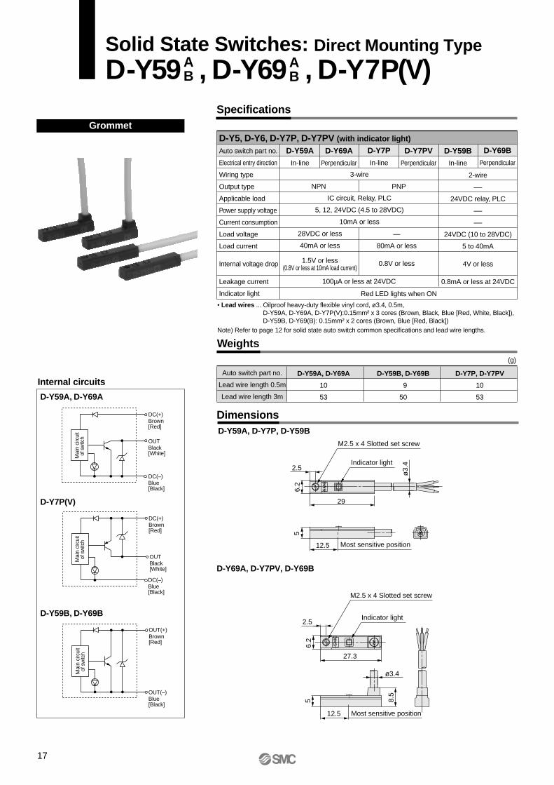
D-Y5, D-Y6, D-Y7P, D-Y7PV (with indicator light)
Auto switch part no.
Electrical entry direction
Wiring type
Output type
Applicable load
Power supply voltage
Current consumption
Load voltage
Load current
Internal voltage drop
Leakage current
Indicator light
D-Y59A
In-line
D-Y69A
Perpendicular
D-Y69B
Perpendicular
D-Y7PV
Perpendicular
D-Y59B
In-line
D-Y59A, D-Y7P, D-Y59B
D-Y69A, D-Y7PV, D-Y69B
(g)
2-wire
—
24VDC relay, PLC
—
—
24VDC (10 to 28VDC)
5 to 40mA
4V or less
0.8mA or less at 24VDC
Internal circuits
D-Y59A, D-Y69A
D-Y59B, D-Y69B
D-Y7P(V)
OUTBlack[White]
DC(+)Brown[Red]
DC(–)Blue[Black]
Mai
n ci
rcui
tof
sw
itch
DC(+)Brown[Red]
DC(–)Blue[Black]
OUTBlack[White]
Mai
n ci
rcui
tof
sw
itch
Mai
n ci
rcui
tof
sw
itch
OUT(+)Brown[Red]
OUT(–)Blue[Black]
NPN
D-Y7P
In-line
28VDC or less
40mA or less
1.5V or less(0.8V or less at 10mA load current)
PNP
Grommet
• Lead wires ... Oilproof heavy-duty flexible vinyl cord, ø3.4, 0.5m,D-Y59A, D-Y69A, D-Y7P(V):0.15mm² x 3 cores (Brown, Black, Blue [Red, White, Black]),D-Y59B, D-Y69(B): 0.15mm² x 2 cores (Brown, Blue [Red, Black])
Note) Refer to page 12 for solid state auto switch common specifications and lead wire lengths.
100µA or less at 24VDC
Red LED lights when ON
Auto switch part no.
Lead wire length 0.5m
Lead wire length 3m
D-Y59A, D-Y69A
10
53
D-Y59B, D-Y69B
9
50
D-Y7P, D-Y7PV
10
53
3-wire
IC circuit, Relay, PLC
5, 12, 24VDC (4.5 to 28VDC)
10mA or less
—
80mA or less
0.8V or less
Solid State Switches: Direct Mounting Type
D-Y59 , D-Y69 , D-Y7P(V)AB
AB
SM
C
SM
C
6.2
5
2.5
29
ø3.
4
12.5
27.3
6.2
5
12.5 Most sensitive position
8.5
2.5
ø3.4
M2.5 x 4 Slotted set screw
M2.5 x 4 Slotted set screw
Indicator light
Indicator light
Most sensitive position
17
18
Internal circuits
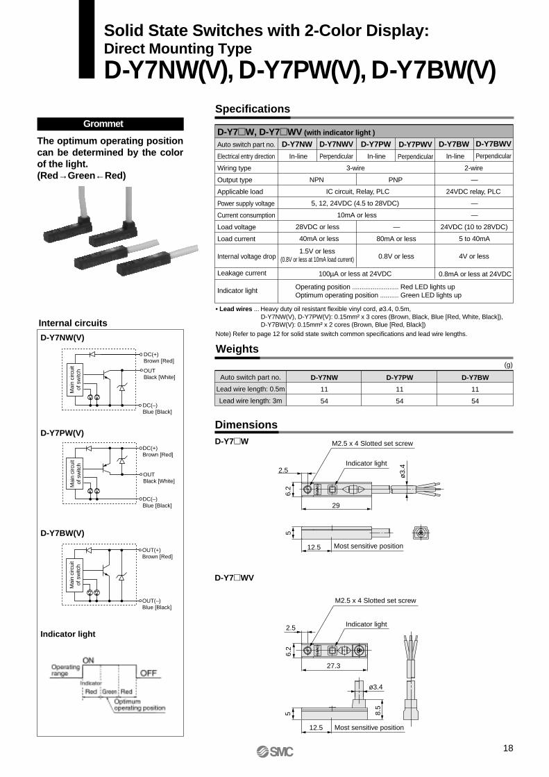
D-Y7NW(V)
D-Y7BW(V)
Indicator light
D-Y7PW(V)
Grommet
DimensionsD-Y7W
D-Y7WV
Specifications
OUTBlack [White]
DC(+)Brown [Red]
DC(–)Blue [Black]
Mai
n ci
rcui
tof
sw
itch
Mai
n ci
rcui
tof
sw
itch
DC(+)Brown [Red]
OUTBlack [White]
DC(–)Blue [Black]
OUT(+)Brown [Red]
OUT(–)Blue [Black]
Mai
n ci
rcui
tof
sw
itch
Weights
Auto switch part no.
Lead wire length: 0.5m
Lead wire length: 3m
D-Y7PW
11
54
D-Y7BW
11
54
D-Y7NW
11
54
(g)
Solid State Switches with 2-Color Display:Direct Mounting Type
D-Y7NW(V), D-Y7PW(V), D-Y7BW(V)
• Lead wires ... Heavy duty oil resistant flexible vinyl cord, ø3.4, 0.5m, D-Y7NW(V), D-Y7PW(V): 0.15mm² x 3 cores (Brown, Black, Blue [Red, White, Black]),D-Y7BW(V): 0.15mm² x 2 cores (Brown, Blue [Red, Black])
Note) Refer to page 12 for solid state switch common specifications and lead wire lengths.
D-Y7W, D-Y7WV (with indicator light )
Auto switch part no.
Electrical entry direction
Wiring type
Output type
Applicable load
Power supply voltage
Current consumption
Load voltage
Load current
Internal voltage drop
Leakage current
Indicator light
D-Y7NW
In-line
3-wire
NPN
IC circuit, Relay, PLC
5, 12, 24VDC (4.5 to 28VDC)
10mA or less
28VDC or less
40mA or less
100µA or less at 24VDC
D-Y7NWV
Perpendicular
D-Y7BWV
Perpendicular
D-Y7PWV
Perpendicular
D-Y7BW
In-line
2-wire
—
24VDC relay, PLC
—
—
24VDC (10 to 28VDC)
5 to 40mA
4V or less
0.8mA or less at 24VDC
D-Y7PW
In-line
PNP
—
80mA or less
0.8V or less
1.5V or less(0.8V or less at 10mA load current)
Operating position ......................... Red LED lights upOptimum operating position .......... Green LED lights up
The optimum operating position can be determined by the color of the light.(Red→Green←Red)
SM
CS
MC
6.2
5
2.5
29
ø3.
4
12.5
27.3
6.2
5
12.5 Most sensitive position
8.5
2.5
ø3.4
M2.5 x 4 Slotted set screw
M2.5 x 4 Slotted set screw
Most sensitive position
Indicator light
Indicator light

19
ø3.
4
Grommet
Dimensions
Improved water-resistant type(for coolant also)
Internal circuits
D-Y7BAL
Weights
Auto switch part no.
Wiring type
Applicable load
Load voltage
Load current
Internal voltage drop
Leakage current
Indicator light
• Operating time .............. 1ms or less• Lead wires .................... Oilproof heavy-duty flexible vinyl cable, ø3.4, 0.15mm², 2 cores
(Brown, Blue [Red, Black]), 3m• Impact resistance ........ 1000m/s²
• Insulation resistance ... 50MΩ or more at 500VDC (between lead wire and case)• Withstand voltage ........ 1000VAC for 1 min. (between lead wire and case)• Ambient temperature ... –10° to 60°C• Enclosure ..................... IEC529 standard IP67 (JISC0920) watertight
D-Y7BAL
2-wire
24VDC relay, PLC
24VDC (10 to 28VDC)
5 to 40mA
4V or less
0.8mA or less at 24VDC
(g)
D-Y7BAL
54
Auto switch part no.
Lead wire length 3m
33 30002
2.5
Indicator light
M2.5 x 4 Slotted set screw
5
6.2
0.4
10.6
Most sensitive position12.5
Indicator light
OFF
ON
Specifications
Operating position ......................... Red LED lights upOptimum operating position .......... Green LED lights up
OUT(+)Brown [Red]
OUT(–)Blue [Black]
Operating range
Red Green RedIndicator
Optimumoperating position
Water-ResistantSolid State Switches with 2-Color DisplayD-Y7BAL 2-Wire Type
Mai
n ci
rcui
tof
sw
itch

20
Basic Wiring
Sink input specifications
2-wire with 2-switch AND connection 2-wire with 2-switch OR connection
2-wire 2-wire
Example: Power supply is 24VDC. Internal voltage drop in switch is 4V.
Example: Load impedance is 3kΩ.Leakage current from switch is 1mA.
Connection Examples for AND (Series) and OR (Parallel)
Examples of Connection to PLC
When two switches are connected in series, a load may malfunction because the load voltage will decline when in the ON state.The indicator lights will light up if both of the switches are in the ON state.
<Solid state>When two switches are connected in parallel, malfunction may occur because the load voltage will increase when in the OFF state.
PLC internal circuitCOM
Switch
InputBlack[White]
Brown[Red]
Blue[Black]
PLC internal circuitCOM
Switch
InputBrown[Red]
Blue[Black] PLC internal circuit
Switch
Input
COM
Blue[Black]
Brown[Red]
PLC internal circuitCOM
Switch
InputBlack[White]
Brown[Red]
Blue[Black]
Switch 1
Switch 2
Load
Blue[Black]
Brown[Red]
Blue[Black]
Brown[Red]
Switch 1
Switch 2
Load
Brown[Red]
Blue[Black]
Brown[Red]
Blue[Black]
3-wireOR connection for NPN output
Switch 1
Switch 2
LoadSwitch 1
Brown[Red]
Switch 2
Black[White]
Blue[Black]
Relay
RelayBlack[White]
Load
Relaycontact
AND connection for NPN output(using relays)
Switch 1
Brown[Red]
Switch 2
Load
Brown[Red]
AND connection for NPN output(performed with switches only)
The indicator lights will light up when both switches are turned ON.
<Reed switch>
3-wire, NPN 3-wire, PNP
Brown [Red]
Blue[Black]
Blue[Black]
Black[White]
Black[White]
Blue[Black]
Brown[Red]
Blue[Black]
Black[White]
Blue[Black]
Black[White]
Brown[Red]
Because there is no current leakage, the load voltage will not increase when turned OFF. However, depending on the number of switches in the ON state, the indicator lights may sometimes grow dim or not light up because of the dispersion and reduction of the current flowing to the switches.Load voltage at ON = – x 2 pcs.
= 24V – 4V x 2 pcs. = 16V
Power supply voltage
Leakagecurrent
Loadimpedance
Internalvoltage
drop
Solid state 3-wire, NPN 2-wireSolid state 3-wire, PNP
(Power supplies for switch and load are separate.)
Blue[Black]
Load
Brown [Red]
Black[White]
Main circuitof switch
Brown[Red]
Load
Blue[Black]
Black[White]
LoadBlue[Black]
Brown[Red]
Load
Blue[Black]
Brown[Red]
Load
Brown[Red]
Blue[Black]
Black[White]
2-wire
Indicatorlight,
protectioncircuit,
etc.
Brown[Red]
Blue[Black]
Load
<Reed switch>
Brown[Red]
Blue[Black]
Load
<Solid state>
Indicatorlight,
protectioncircuit,
etc.
Main circuitof switch
Main circuitof switch
Main circuitof switch
Main circuitof switch
The connection method will vary depending on the applicable PLC input specifications.
Load voltage at OFF = x 2 pcs. x
= 1mA x 2 pcs. x 3kΩ= 6V
Auto Switch Connections and Examples

Series MY1WMade to Order SpecificationsContact SMC for detailed dimensions, specifications, and lead times.
1 Long stroke
Stroke range: 2001 to 3000mm
Example) MY1MW40G-2999L-Z73-XB11
-XB11
MY1 M W XB11Series: Bore size
Bore size Stroke Auto switch type No. of auto switches
MC
Slide bearing guide type
Cam follower guide type
10 16 20 25 32 40 50 63 80 100
2 Dust seal band NBR lining specification
Example) MY1MW40G-300L-Z73-XC67
-XC67
Series: Bore size
MC
Slide bearing guide type
Cam follower guide type
10 16 20 25 32 40 50 63 80 100
For ordering dust seal band (NBR lining) only
Example) MY25-16BNW-300
MY 16 B NDust seal band hexagon sockethead set screw thread
Dust seal bandNBR lining
Bore size Stroke
NilW
Black zinc chromatedNickel plated
Made toOrder
3 Holder mounting bracket .............................. , Holder mounting brackets are used to fix the stroke adjusting unit at an intermediate stroke position.
Holder mounting bracket .......... -X416 Holder mounting bracket .......... -X417
NilWZAL
AZLZNilWAL
A, L, AS, LS
A, L
ALALALAL
A, L, AS, LS A, LAL AL
X416 on one sideX416 on both sidesX416 on one side, X417 on the other sideX416 on A unit sideX416 on L unit sideX416 on A unit side, X417 on the other sideX416 on L unit side, X417 on the other sideX417 on one sideX417 on both sidesX417 on A unit sideX417 on L unit side
Stroke adjusting unit CombinationSymbol
Mounting pcs.Combination description
Holdermountingbracket
Note) For AS and LS, stroke adjusting unit is mounted on one side only.
16202532405063
5.66
11.5 12162025
–5.6 to –11.2 –6 to –12
–11.5 to –23 –12 to –24–16 to –32–20 to –40–25 to –50
11.2122324324050
Bore size(mm)
Spacerlengths
-X416 (one side)Adjustment range
MY1MW MY1CW–11.2 to –16.8
–12 to –18 –23 to –34.5
–24 to –36–32 to –48–40 to –60–50 to –75
Spacerlength
-X417 (one side)Adjustment range
MY1MW MY1CW
Fine stroke adjustment range (mm)
Holder mounting bracket illustration
MY1MW/MY1CW
Slider (Piston yoke)Stroke adjusting unit
Head cover
Spacer length (X417)
Spacer length (X416)
Spacer length
Stroke adjusting unit Holdermounting bracket
-X416, X417
Series: Bore size
StrokeNote) Indicates the stroke prior to mounting the stroke adjusting unit.
Refer to the table below for applicable symbols.
Refer to the table below for applicable symbols.
Refer to the table below for applicable symbols.
MC
Slide bearing guide typeCam follower guide type
10 16 20 25 32 40 50 63 80 100
MY1 M W Bore size 300 L X416
X416
X417
Stroke adjusting unit
Holder mounting bracket
Combination symbol
X4161211111
X417
1
111211
21
Available with long strokes exceeding standard stroke range. The stroke can be set in 1mm increments.
The standard vinyl chloride lining specification is changed to NBR lining for improved oil resistance and peeling resistance.Note) Consult with SMC for specific details on oil resistance.
Refer to "Dust seal band" under the seal parts on the construction page of each series for details.
Contact SMC for marked items.
(Any fine strokes outside the parameters in the adjustment ranges above areconsidered to be a special order and processed accordingly.)
MY1 M W XC67Bore size Stroke Auto switch type No. of autoswitches

3 Holder mounting bracket (Continued) ………………
Example
• For L units with one each of X416 and X417
MY1W25G-300L-X416Z
L unitL unit
-X416, X417
4 Copper-free specification 20-Copper-free compatible.Note) Not available for cylinders with side seal (MY1WK).
20 MY1 M Bore size Stroke Auto switch type No. of autoswitches
X417X416
L unitA unit
X417
Example• Stroke adjusting unit with holder mounting bracket
MYM-A25L-X416 (L unit for MY1W25 and X416 bracket)
• Holder mounting bracket only
MYM-A25L-X416N (MY1W25 and X416 bracket for L unit)
MYM-A16A X417
Stroke adjusting unit modelNote) Refer to "Option" on page 3.
Holder mounting bracket Holder mounting bracket
Holder mounting bracketX416X417
Stroke adjusting unit+
Holder mounting bracket
Combination symbol
Nil
N
• For A and L units, where X417 is mounted on the A unit side only and nothing is mounted on the L unit side.
MY1W25G-300AH-X417A
How to order stroke adjusting unit or holder mounting bracket by itself:
Holder mounting bracket only
Series: Bore sizeMC
Slide bearing guide typeCam follower guide type
10 16 20 25 32 40 50 63 80 100
Holder mounting bracket
Stroke adjusting unit
Made to Order Specifications
22
W

23
Selection Flow Chart
Operating conditionsm: Load weight (kg)V: Speed (mm/s)P: Operating pressure (MPa)
Mounting orientation Guide type (Accuracy)
Tentative selection of cylinder modelMY1MW: Slide bearing guide typeMY1CW: Cam follower guide type
Load weightm ≤ m max.
Determination ofallowable moment
[Σα] ≤ 1
L-typeStroke adjusting
unitAir cushion
Externalcushioning
unit ∗
Examination of port variationsand auto switch mounting (type)
Model selectioncompleted
Reevaluate operating conditions
Select larger cylinder size.
Change guide type.
Select larger cylinder size.
Change guide type.
Sel
ect l
arge
r cy
linde
r si
ze.
Standard or centralized piping
NO
NO
NONO NO
YES YESYES
YES
YES
Series MY1WModel Selection 1
Standards for Tentative Model Selection
Cylinder model
MY1MW
MY1CW
Guide type
Slide bearing guide
Cam follower guide
Standards for guide selection
Slide table accuracy approx. ±0.12mm Note)
Slide table accuracy approx. ±0.05mm Note)
Graphs for relatedallowable values
Refer to page 26
Refer to page 27
M2: Rolling M1: Pitching
M3: Yawing
∗ These accuracy values for each guide should be used only as a guide during selection. Contact SMC when guaranteed accuracy for MY1CW is required.
Note) "Accuracy" here means displacement of the slide table (at stroke end) when 50% of the allowable moment shown in the catalog is applied (reference value).
This section illustrates the standard model selection procedure to help you choose the most suitable cylinders from Series MY1MW/MY1CW for your application needs.
Select a guide suitable to the required application.
∗ For external cushioning unit, the installation of a suitable cushioning mechanism near the load center of gravity by the customer's side is recommended. The model selection procedure described in this page is applicable to all mechanically jointed rodless cylinders.Refer to the separate instruction manual for further details. If you have any questions, please contact SMC.
Examination of cushioningmechanism at stroke end
M₃E
FE
M₃
Y
υa
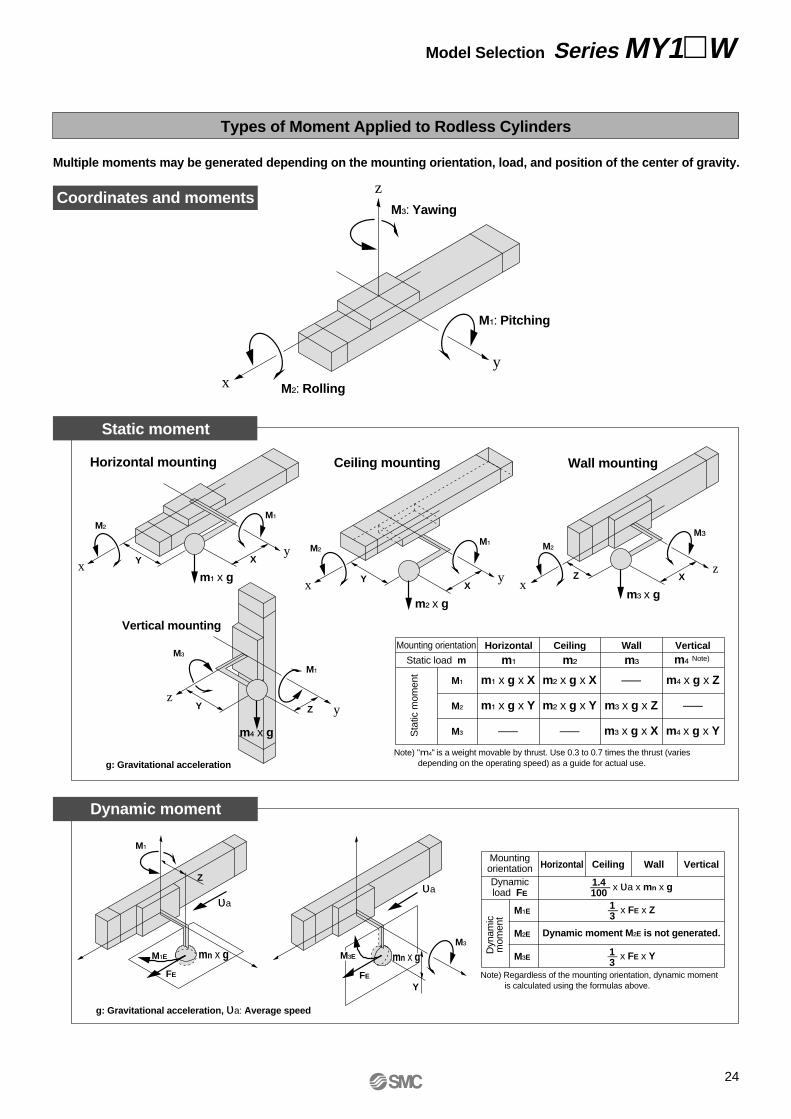
Types of Moment Applied to Rodless Cylinders
Multiple moments may be generated depending on the mounting orientation, load, and position of the center of gravity.
Coordinates and moments
Static moment
Dynamic moment
z
y
M₃: Yawing
x M₂: Rolling
M₁: Pitching
m₃ x gx
M₂
z
M₃
XZ
y
m₁ x g
M₁
Xx
M₂
Y
y
m₂ x g
M₁
Xx
M₂
Y
m₄ x g
M₁
Z
M₃
zyY
M₁
mn x gM₁E
FE
Z
υa
Horizontal mounting Wall mounting
Vertical mounting
Ceiling mounting
Mounting orientation
Static load mHorizontal
m₁
Ceiling
m₂
Wall
m₃
Verticalm₄ Note)
Sta
tic m
omen
t
M₁
M₂
M₃
m₁ x g x X
m₁ x g x Y
–––
m₂ x g x X
m₂ x g x Y
–––
–––
m₃ x g x Z
m₃ x g x X
m₄ x g x Z
–––
m₄ x g x Y
MountingorientationDynamicload FE
Horizontal Ceiling Wall Vertical
Dyn
amic
mom
ent
M₁E
M₂E
M₃E
—— x υa x mn x g
— x FE x Z
Dynamic moment M₂E is not generated.
— x FE x Y
13
1.4100
13
g: Gravitational acceleration
g: Gravitational acceleration, υa: Average speed
Note) "m₄" is a weight movable by thrust. Use 0.3 to 0.7 times the thrust (varies depending on the operating speed) as a guide for actual use.
mn x gNote) Regardless of the mounting orientation, dynamic moment
is calculated using the formulas above.
Model Selection Series MY1W
24

Maximum Allowable Moment/Maximum Load Weight
Maximum allowable moment
Maximum load weight
Moment (N⋅m)
Load weight (kg)m₁
M₁ = F₁ x L₁F₁
L1
F2
L2
M₂ = F₂ x L₂
m₂
L3
M₃ = F₃ x L₃F3
m₃
FE
ME
m
L₁
υ
1.4100
Select the moment from within the range of operating limits shown in the graphs. Note that the maximum load weight value may sometimes exceed even the operating limits shown in the graphs. Therefore, check the allowable load for the selected conditions.
<Calculation of guide load factor>1. Three factors must be considered when computing calculations for selection:
a) Maximum load weightb) Static momentc) Dynamic moment (at the time of impact with stopper)
To evaluate, use υa (average speed) for a and b, and υ (impact speed υ = 1.4υa) for c.Calculate m max for (1) from the maximum allowable load graph (m₁, m₂, and m₃), and Mmax for (2) and (3) from the maximum allowable moment graph (M₁, M₂, and M₃).
2. Reference formulas [Dynamic moment at impact] Use the following formulas to calculate dynamic moment when taking stopper impact into consideration.mFFE
υaM
1.4 υ = 1.4υa (mm/s) FE = –––– υa⋅g⋅m 100 1 ∴ ME = ––– ⋅ FE ⋅ L₁ = 0.05υa m L₁ (N⋅m) 3
Note 4) ——– υa is a dimensionless coefficient for calculating impact force.
Note 5) Average load coefficient (= ––):
This coefficient is for averaging the maximum load moment atthe time of stopper impact in order to calculate the cylinder's service life.
3. Refer to pages 30 and 31 for detailed selection procedures.
: Impact speed (mm/s): Distance to the load center of gravity (m): Dynamic moment (N⋅m): Gravitational acceleration (9.8m/s²)
: Load mass (kg): Load (N): Load equivalent to impact (impact with stopper): Average speed (mm/s): Static moment (N⋅m)
The above values are the maximum allowable values for moment and load. Refer to each graph on pages 26 and 27 regarding the maximum allowable moment and maximum load weight for a particular piston speed.
Note 1) Moment caused by the load with a cylinder in resting condition.
Note 2) Moment caused by the load equivalent to impact at the stroke end (at the time of impact with stopper).
Note 3) Depending on the shape of the work piece, multiple moments may be generated. In such cases, the total sum of the load factors (Σα) is the total of all such moments.
Total sum of guide load factors Σα = –––––––––––––––––––––– + ––––––––––––––––––––– + –––––––––––––––––––––––– ≤1Load mass [m]
Maximum allowable load [m max]
Static moment [M] Note 1)
Allowable static moment [Mmax]
Dynamic moment [ME] Note 2)
Allowable dynamic moment [MEmax]
Select the load weight from within the range of limits shown in the graphs. Note that the maximum allowable moment value may sometimes exceed even the operating limits shown in the graphs. Therefore, also check the allowable moment for the selected conditions.
υL₁
ME
g
13
Note 5)
Note 4)
Model
MY1MW
MY1CW
Bore size(mm)
1620253240506316202532405063
Maximum allowable moment (N⋅m)
M1 6.0
10
15
30
59
115
140
6.0
10
15
30
60
115
150
M2 3.0
5.2
9.0
15
24
38
60
3.0
5.0
8.5
14
23
35
50
M3 1.0
1.7
2.4
5.0
8.0
15
19
2.0
3.0
5.0
10
20
35
50
Maximum load weight (kg)
m1 18
26
38
57
84
120
180
18
25
35
49
68
93
130
m2 7
10.4
15
23
33
48
72
7
10
14
21
30
42
60
m3
2.1
3
4.5
6.6
10
14
21
2.1
3
4.2
6
8.2
11.5
16
Caution• The cylinder should be
mounted in m1 orientation if maximum dustproofing is required.
25
Series MY1W

26
MY1MW: M1200
100
30
20
10
54
3
1
0.5100 200 300 400 500 1000 1500
Piston speed (mm/s)
Mom
ent (
N⋅m
)
5040
2
MY1MW: M2
10
54
3
2
1
0.50.4
0.3
0.2100 200 300400 500 1000 1500
Piston speed (mm/s)
Mom
ent (
N⋅m
)
20
30
4050
MY1MW20MY1MW20
MY1MW25MY1MW25
MY1MW32MY1MW32
MY1MW40MY1MW40
MY1MW50MY1MW50
MY1MW63MY1MW63
MY1MW: M3
20
10
54
3
2
100 200 300400500 1000 1500
Piston speed (mm/s)
Mom
ent (
N⋅m
)
1
0.50.4
0.3
0.2
0.1
0.05
MY1M20MY1M20
MY1MW16MY1MW16
MY1MW20MY1MW20
MY1MW25MY1MW25
MY1MW32MY1MW32
MY1MW40MY1MW40
MY1MW50MY1MW50MY1MW63MY1MW63
MY1MW16
MY1MW20
MY1MW25
MY1MW32
MY1MW40
MY1MW50MY1MW63
MY1MW: m1
100
50
2
100 200 300 400500 1000 1500
Piston speed (mm/s)
Load
wei
ght (
kg)
Load
wei
ght (
kg)
Load
wei
ght (
kg)
3
45
10
20
30
40
1
200
MY1MW: m2
5
200 300400500 1000 1500
Piston speed (mm/s)
4050
100
100
30
20
10
4
3
2
1 MY1MW16MY1MW16
MY1MW20MY1MW20
MY1MW25MY1MW25
MY1MW32MY1MW32
MY1MW40MY1MW40
MY1MW50MY1MW50
MY1MW63MY1MW63
MY1MW16
MY1MW20
MY1MW25
MY1MW32
MY1MW40
MY1MW50
MY1MW63
0.50.4
0.3
MY1MW: m3
1
0.50.4
0.3
100 200 300400500 1000 1500
Piston speed (mm/s)
2
3
45
10
MY1MW16MY1MW16
MY1MW20MY1MW20
MY1MW25MY1MW25
MY1MW32MY1MW32
MY1MW40MY1MW40
MY1MW50MY1MW50
MY1MW63MY1MW63
MY1MW16
MY1MW20
MY1MW25
MY1MW32
MY1MW40
MY1MW50
MY1MW63
20
0.2
0.1
30
MY1M16MY1M16MY1MW16
MY1MW20
MY1MW25
MY1MW32
MY1MW40
MY1MW63
MY1MW50
MY1MW16MY1MW16
MY1MW20MY1MW20
MY1MW25MY1MW25
MY1MW32MY1MW32
MY1MW40MY1MW40
MY1MW63MY1MW63
MY1MW50MY1MW50
MY1MW16
MY1MW20
MY1MW25
MY1MW32
MY1MW40
MY1MW63
MY1MW50
MY1MW16MY1MW16MY1MW16MY1MW16MY1MW16
MY1MW20
MY1MW25
MY1MW32
MY1MW40
MY1MW50
MY1MW63
MY1MW16
Maximum Allowable Moment: MY1MW
Maximum Load Weight: MY1MW
Mechanically Jointed Rodless Cylinder with Protective Cover Series MY1W
MY1MW20MY1MW20
MY1MW25MY1MW25
MY1MW32MY1MW32
MY1MW40MY1MW40
MY1MW50MY1MW50MY1MW63MY1MW63
MY1MW20
MY1MW25
MY1MW32
MY1MW40
MY1MW50MY1MW63

27
Series MY1W
Maximum Allowable Moment/Maximum Load Weight
Maximum Allowable Moment: MY1CW
Maximum Load Weight: MY1CW
MY1CW: M1
100 200 300400500 1000 1500
Piston speed (mm/s)
Mom
ent (
N⋅m
)
10
5
4
3
2
1
20
30
40
200
50
100
MY1CW16MY1CW16
MY1CW20MY1CW20
MY1CW25MY1CW25
MY1CW32MY1CW32
MY1CW40MY1CW40
MY1CW50MY1CW50
MY1CW63MY1CW63
MY1CW16
MY1CW20
MY1CW25
MY1CW32
MY1CW40
MY1CW50
MY1CW63
MY1CW: M2
10
5
4
3
2
1
0.5
100 200 300400 500 1000 1500
Piston speed (mm/s)
Mom
ent (
N⋅m
)
20
30
4050
MY1CW16MY1CW16
MY1CW20MY1CW20
MY1CW25MY1CW25
MY1CW32MY1CW32
MY1CW40MY1CW40
MY1CW50MY1CW50
MY1CW63MY1CW63
MY1CW16
MY1CW20
MY1CW25
MY1CW32
MY1CW40
MY1CW50
MY1CW63
MY1CW: M3
20
10
54
3
2
100 200 300400500 1000 1500
Piston speed (mm/s)
Mom
ent (
N⋅m
)
1
0.5
30
40
50
MY1CW16MY1CW16
MY1CW20MY1CW20
MY1CW25MY1CW25
MY1CW32MY1CW32
MY1CW40MY1CW40
MY1CW50MY1CW50
MY1CW63MY1CW63
MY1CW16
MY1CW20
MY1CW25
MY1CW32
MY1CW40
MY1CW50
MY1CW63
MY1CW: m1
100
50
2
100 200 300 400500 1000 1500
Piston speed (mm/s)
Load
wei
ght (
kg)
Load
wei
ght (
kg)
Load
wei
ght (
kg)
3
45
10
20
30
40
1
MY1CW16MY1CW16
MY1CW20MY1CW20
MY1CW25MY1CW25
MY1CW32MY1CW32
MY1CW40MY1CW40
MY1CW50MY1CW50
MY1CW63MY1CW63
MY1CW16
MY1CW20
MY1CW25
MY1CW32
MY1CW40
MY1CW50
MY1CW63
200
MY1CW: m2
5
200 300400500 1000 1500
Piston speed (mm/s)
4050
100
100
30
20
10
4
3
2
1
MY1CW16MY1CW16
MY1CW20MY1CW20
MY1CW25MY1CW25
MY1CW32MY1CW32
MY1CW40MY1CW40
MY1CW50MY1CW50
MY1CW63MY1CW63
MY1CW16
MY1CW20
MY1CW25
MY1CW32
MY1CW40
MY1CW50
MY1CW63
MY1CW: m3
1
0.5
0.4
0.3
0.2100 200 300400500 1000 1500
Piston speed (mm/s)
2
3
4
5
10
30
20
MY1CW16MY1CW16
MY1CW20MY1CW20
MY1CW25MY1CW25
MY1CW32MY1CW32
MY1CW40MY1CW40
MY1CW50MY1CW50
MY1CW63MY1CW63
MY1CW16
MY1CW20
MY1CW25
MY1CW32
MY1CW40
MY1CW50
MY1CW63

28
20001500
1000
500400300
200
1002 3 5 10 20 50
For ø50 Horizontal impact: P = 0.5MPa
100304 40
Air cushion
L-unit
20001500
1000
500400300
200
1002 3 4 5 10 20 50
Load weight (kg)
Load weight (kg)
For ø40 Horizontal impact: P = 0.5MPa
Air cushion
L-unit
20001500
1000
500400300
200
1002 3 4 5 10 20 30
Load weight (kg)
For ø32 Horizontal impact: P = 0.5MPa
40 50
Air cushion
L-unit
100
20001500
1000
500400300
200
1001 2 3 4 5 10 20 30
Load weight (kg)
For ø25 Horizontal impact: P = 0.5MPa
40
Air cushion
L-unit
50
20001500
1000
500400300
200
1001 2 3 4 5 10 20 30
Load weight (kg)
For ø20 Horizontal impact: P = 0.5MPa
400
Air cushion
L-unit
50
20001500
1000
500400300
200
1001 2 3 4 5 10 20 30
Load weight (kg)
Impa
ct s
peed
(m
m/s
)
For ø16 Horizontal impact: P = 0.5MPa
L-unitAir cushion
0.5
Cushion Capacity
Cushion selection Absorption capacity of air cushion and stroke adjusting units
Impa
ct s
peed
(m
m/s
)
Impa
ct s
peed
(m
m/s
)
Impa
ct s
peed
(m
m/s
)
Impa
ct s
peed
(m
m/s
)
Impa
ct s
peed
(m
m/s
)
20001500
1000
500400300
200
1002 3 5 10 20 50
Load weight (kg)
Impa
ct s
peed
(m
m/s
)
For ø63 Horizontal impact: P = 0.5MPa
30 1004
L-unitAir cushion
Mechanically Jointed Rodless Cylinder with Protective Cover Series MY1W
<Air cushion> Air cushions are a standard feature for mechanically jointed rodless cylinders.The air cushion mechanism is incorporated to prevent excessive impact of the piston at the stroke end during high speed operation. The purpose of air cushion, thus, is not to decelerate the piston near the stroke end.The ranges of load and speed that air cushions can absorb are within the air cushion limit lines shown in the graphs.
<Stroke adjusting unit with shock absorber>Use this unit when operating with a load or speed exceeding the air cushion limit line, or when cushioning is required outside of the effective air cushion stroke range due to stroke adjustment.L unitUse this unit when the cylinder stroke is outside of the effective air cushion range even if the load and speed are within the air cushion limit line, or when the cylinder is operated in a load and speed range above the air cushion limit line or below the L-unit limit line.
Air cushion stroke Unit: mm
Bore size (mm)
16
20
25
32
40
50
63
Cushion stroke
12
15
15
19
24
30
37
1. Perform stroke adjustment using the adjusting bolt as shown in the picture below.
When the effective stroke of the shock absorber decreases due to stroke adjustment, the absorption capacity decreases dramatically. Adjust the adjusting bolt so that it is secure at a position where it protrudes approximately 0.5mm beyond the shock absorber.
2. Do not use a shock absorber and air cushion together.
Caution
Adjusting bolt
Shock absorber
0.5

Calculation of absorbed energy for strokeadjusting unit with shock absorber (N⋅m)
1——m⋅υ²
2
F⋅s F⋅s + m⋅g⋅s F⋅s – m⋅g⋅s
E₁ + E₂
Tightening torque for strokeadjusting unit holding bolts
Tightening torque for stroke adjustingunit lock plate holding bolts (N⋅m)
υm
s
s
υ m s
υ m
Lock plate holding bolt
HorizontalVertical
(downward)Vertical
(upward)
Type of impact
Kinetic energyE₁
Thrust energyE₂
Symbols
υ: Speed of impacting object (m/s)
m: Weight of impacting object (kg)
F: Cylinder thrust (N)
g: Gravitational acceleration (9.8m/s²)
s: Shock absorber stroke (m)
Shock absorberLock plate
Unit holding boltAdjusting bolt lock nut
CautionTake precautions to avoid getting your hands caught in the unit during adjustment.When using a product with stroke adjusting unit, the space between the slide table (slider) and the stroke adjusting unit is very narrow. Care should be taken to avoid the danger of hands getting caught in this small space.
<Fastening of unit> The unit can be secured by evenly tightening the four unit holding bolts.
Do not operate with the stroke adjusting unit fixed in an intermediate position.When the stroke adjusting unit is fixed in an intermediate position, slippage can occur depending on the amount of energy released at the moment of an impact. In such cases, the use of adjusting bolt mounting brackets, available per Made to Order specifications – X 416 and – X 417, is recommended.Consult with SMC for other lengths. (Refer to "Tightening torque for stroke adjusting unit holding bolts" values in the chart at the upper left corner of this page.)
<Stroke adjustment with adjusting bolt> Loosen the adjusting bolt lock nut, and adjust the stroke from the lock plate side using a hexagon wrench. Retighten the lock nut.
<Stroke adjustment with shock absorber>Loosen the two lock plate holding bolts and adjust the stroke by turning the shock absorber. Then, evenly tighten the lock plate holding bolts to secure the shock absorber.Avoid excessive tightening of the holding bolts (except for ø16, ø20, ø50, and ø63). (Refer to "Tightening torque for stroke adjusting unit lock plate holding bolts" above left.)
Note) Although the lock plate may slightly bend due to tightening of the lock plate holding bolt, this does not a affect the shock absorber and locking function.
Caution
Specific Product Precautions
Note) The speed of the impacting object is measured at the moment of impact with the shock absorber.
Be sure to read before handling.Refer to pages 32 through 38 for Safety Instructions and Auto Switch Precautions.
Absorbed energyE
Cushion Capacity
Bore size (mm)
16
20
25
32
40
50
63
Unit
A
L
A
L
A
L
A
L
A
L
A
L
A
L
Tightening torque
0.6
1.5
3.0
5.0
12
12
24
(N⋅m)
Bore size (mm)
25
32
40
Unit
L
L
L
Tightening torque
1.2
3.3
3.3
29
Series MY1W

m₁: Weight
m₁ max (from of graph MY1MW: m₁ on page 31) = 84 (kg) ...............................
Load factor α₁ = m₁/m₁ max = 6.525/84 = 0.08
M₁: Moment
M₁ max (from of graph MY1MW: M₁ on page 31) = 59 (N⋅m) ............................................................
M₁ = m₁ x g x X = 6.525 x 9.8 x 138.5 x 10-³ = 8.86 (N⋅m)
Load factor α2 = M₁/M₁ max = 8.86/59 = 0.15
3 Composite center of gravity calculation ——————————————————————————————
m₁ = Σmn
= 0.88 + 4.35 + 0.795 + 0.5 = 6.525kg
X = –––– x Σ (mn x Xn)
= ––––––– (0.88 x 65 + 4.35 x 150 + 0.795 x 150 + 0.5 x 150) = 138.5mm
Y = —— x Σ (mn x Yn)
= ——— (0.88 x 0 + 4.35 x 0 + 0.795 x 111 + 0.5 x 210) = 29.6mm
Z = —— x Σ (mn x Zn)
= –––––– (0.88 x 5 + 4.35 x 42.5 + 0.795 x 42.5 + 0.5 x 42.5) = 37.4mm
1m₁
1m₁
1m₁
16.525
16.525
16.525
Wa: Connection plate t = 10 (880g)
Wd: Work piece (500g)
Wc: MHL2-16D1 (795g)
Wb: MGGLB25-200 (4.35kg)
MY1MW40-500
X
m1
m1
M1
210 65
150
5
42.5
111
Z
Y
Y
X
xy
z
x z
y
x
z y
x y
z
Wa
Wb
Wc
Wd
0.88kg
4.35kg
0.795kg
0.5kg
65mm
150mm
150mm
150mm
X-axisXn
0mm
0mm
111mm
210mm
Y-axisYn
Z-axisZn
n = a, b, c, d
5mm
42.5mm
42.5mm
42.5mm
Calculation of Guide Load Factor
1 Operating conditions ———————————————————————————————————————
Cylinder ……………….….. MY1MW40-500Average operating speed υa .… 200mm/sMounting orientation ……... Horizontal mounting
Mounting orientation1. Horizontal mounting 2. Wall mounting
3. Ceiling mounting 4. Vertical mounting
Work piece no.
Massmn
Center of gravity
Weight and center of gravity for each work piece
2 Load blocking ——————————————————————————————————————————
4 Calculation of load factor for static load ————————————————————————————————
Series MY1WModel Selection 2This section illustrates the standard model selection procedure using the actual operating conditions as one of the examples.
30

MY1MW: M1 MY1MW: M3MY1MW: M2MY1MW: m1
5 Calculation of load factor for dynamic moment ——————————————————————————
6 Sum and examination of guide load factors ———————————————————————————
Equivalent load FE at impact
FE = ——— x υa x g x m = ——— x 200 x 9.8 x 6.525 = 179.1 (N)
M1E: Moment
M₁E max (from of graph MY1MW: M₁ where 1.4υa = 280mm/s) = 42.1 (N⋅m) ……………
M₁E = —— x FE x Z = —— x 179.1 x 37.4 x 10-³ = 2.23 (N⋅m)
Load factor α₄ = M₁E/M₁E max = 2.23/42.1 = 0.05
M3E: Moment
M₃E max (from of graph MY1MW: M₃ where 1.4υa = 280mm/s) = 5.7 (N⋅m) ……………………
M₃E = ——x FE x Y = —— x 179.1 x 29.6 x 10-³ = 1.77 (N⋅m)
Load factor α₅ = M₃E/M₃E max = 1.77/5.7 = 0.31
1.4100
13
13
13
13
1.4100
M₂: Moment
M₂ max (from of graph MY1MW: M₂) = 24 (N⋅m) ……………………………………………
M₃ = m₁ x g x Y = 6.525 x 9.8 x 29.6 x 10-³ = 1.89 (N⋅m)
Load factor α₃ = M₂/M₂ max = 1.89/24 = 0.08
m₁
M₂
M₁
M₃
Y
Y
FE
FE
Z
M₃E
10
54
3
100 200 300 400500 1000 1500
20
30
4050
100
2
1
200200
100
30
20
10
54
3
1
0.5100 200 300 400 500 1000 1500
5040
2
MY1M20MY1M20MY1M20MY1M20
MY1M50MY1M50MY1M50MY1M50MY1M63MY1M63MY1M63MY1M63
MY1MW20
MY1MW25MY1MW25
MY1MW32MY1MW32
MY1MW40MY1MW40
MY1MW50MY1MW63
MY1MW16MY1MW16
10
54
3
2
1
0.50.4
0.3
0.2100 200 300400 500 1000 1500
20
30
4050
MY1M25MY1M25MY1M25MY1M25
MY1M32MY1M32MY1M32MY1M32
20
10
54
3
2
100 200 300400 500 1000 1500
1
0.50.4
0.3
0.2
0.1
0.05
MY1M16MY1M16MY1M16MY1M16
MY1M20MY1M20MY1M20MY1M20
MY1M63MY1M63MY1M63MY1M63
MY1MW16
MY1MW20
MY1MW63MY1MW50MY1MW50
M₁E
42 5
3
MY1M20MY1M20
MY1M40MY1M40
MY1M50MY1M50
MY1M63MY1M63
MY1MW20
MY1MW40
MY1MW50
MY1MW63
MY1M16MY1M16MY1MW16
1
Load weight Allowable moment
Piston speed (mm/s)
Mom
ent (
N⋅m
)
Piston speed (mm/s)
Mom
ent (
N⋅m
)
Piston speed (mm/s)
Mom
ent (
N⋅m
)
Load
mas
s (k
g)
Piston speed (mm/s)
Σα = α₁ + α₂ + α₃ + α₄ + α₅ = 0.67 ≤ 1The above calculation is within the allowable value, and therefore the selected model can be used. Select a shock absorber separately.In an actual calculation, when the total sum of guide load factors Σα in the formula above is more than 1, consider either decreasing the speed, increasing the bore size, or changing the product series. This calculation can be easily made using the "SMC Pneumatics CAD System".
31
Series MY1W
Calculation of Guide Load Factor
MY1MW32MY1MW32MY1MW32
MY1MW25MY1MW25MY1MW25
MY1MW40
MY1MW32
MY1MW25
MY1MW16
MY1MW63MY1MW63
MY1MW25
MY1MW32MY1MW32
MY1MW40MY1MW40
MY1MW50MY1MW50
MY1MW63
MY1MW20MY1MW20
MY1MW50
MY1MW40
MY1MW32
MY1MW20
MY1MW16MY1MW16MY1MW16
MY1MW50
MY1MW40
MY1MW32
MY1MW25

32
Series MY1W
Safety Instructions
Note 1) ISO 4414: Pneumatic fluid power -- Recommendations for the application of equipment to transmission and control systems
Note 2) JIS B 8370: General Rules for Pneumatic Equipment
Warning
Caution : Operator error could result in injury or equipment damage.
Warning : Operator error could result in serious injury or loss of life.
Danger : In extreme conditions, there is a possible result of serious injury or loss of life.
These safety instructions are intended to prevent a hazardous situation and/or equipment damage. These instructions indicate the level of potential hazard by a label of "Caution", "Warning", or "Danger". To ensure safety, be sure to observe ISO 4414 Note 1), JIS B 8370 Note 2) and other safety practices.
1. The compatibility of pneumatic equipment is the responsibility of the person who designs the pneumatic system or decides its specifications.Since the products specified here are used in various operating conditions, their compatibility with the specific pneumatic system must be based on specifications or after analysis and/or tests to meet your specific requirements.
2. Only trained personnel should operate pneumatically operated machinery and equipment.Compressed air can be dangerous if handled incorrectly. Assembly, handling or repair of pneumatic systems should be performed by trained and experienced operators.
3. Do not service machinery/equipment or attempt to remove components until safety is confirmed.1. Inspection and maintenance of machinery/equipment should only be performed after confirmation of
safe locked-out control positions.
2. When equipment is to be removed, confirm the safety process as mentioned above. Cut the supply pressure for this equipment and exhaust all residual compressed air in the system.
3. Before machinery/equipment is restarted, take measures to prevent shooting-out of cylinder piston rod, etc. (Bleed air into the system gradually to create back pressure.)
4. Contact SMC if the product is to be used in any of the following conditions:1. Conditions and environments beyond the given specifications, or if product is used outdoors.
2. Installation on equipment in conjunction with atomic energy, railway, air navigation, vehicles, medical equipment, food and beverages, recreation equipment, emergency stop circuits, press applications, or safety equipment.
3. An application which has the possibility of having negative effects on people, property, or animals, requiring special safety analysis.

Series MY1WActuator Precautions 1Be sure to read before handling.
1. There is a danger of sudden or erratic action by cylinders if sliding parts of machinery are twisted and changes in forces occur. In such cases, bodily injury may occur, e.g., by catching hands or feet in the machinery, or damage to the machinery itself may occur. Therefore, the machinery should be adjusted to operate smoothly and designed to prevent such dangers.
2. Securely tighten all stationary parts and connected parts so that they will not become loose.Especially when a cylinder operates with high frequency or is installed where there is a lot of vibration, ensure that all parts remain secure.
3. A deceleration circuit or shock absorber may be required.When a driven object is operated at high speed or the load is heavy, a cylinder’s cushion will not be sufficient to absorb impact. Install a deceleration circuit to reduce the speed before cushioning, or install an external shock absorber to relieve impact. In this case, the rigidity of the machinery should also be examined.
4. Take into account a possible drop in operat-ing pressure due to a power outage.When a cylinder is used as a clamping mechanism, there is a danger of work pieces dropping if there is a decrease in clamping force due to a drop in circuit pressure caused by a power outage. Therefore, safety equipment should be installed to prevent damage to machinery and bodily injury. Suspension mechanisms and lifting devices also require drop prevention measures.
5. Take into account a possible loss of power source.Measures should be taken to protect against bodily injury and equipment damage in the event that there is a loss of power to equipment controlled by air pressure, electricity, or hydraulics.
6. Design circuitry to prevent sudden lurching of driven objects.Take special care when a cylinder is operated by an exhaust center type directional control valve or when it is starting up after residual pressure is exhausted from the circuit. The piston and its driven object will lurch at high speed if pressure is applied to one side of the cylinder because of the absence of air pressure inside the cylinder. Therefore, equipment should be selected and circuits designed to prevent sudden lurching because when this occurs, there is a danger of bodily injury, particularly to limbs, and/or damage to equipment.
7. Take into account emergency stops.Design the system so that bodily injury and/or damage to machinery and equipment will not occur when machinery is stopped by a manual emergency stop or a safety device triggered by abnormal conditions.
8. Consider a system's action when operation is restarted after an emergency stop or an ab-normal stop.Design machinery so that bodily injury or equipment damage will not occur upon restart of operation.
When the cylinder has to be reset at the starting position, install safe manual control equipment.
1. Confirm the specifications.The products featured in this catalog are designed for use in industrial compressed air systems. If the products are used in conditions where pressure and/or temperature are outside the range of specifications, damage and/or malfunction, may occur. Do not use in these conditions. (Refer to specifications.)
Consult with SMC if fluid other than compressed air is to be used.
2. Intermediate stopsWhen intermediate stopping of a cylinder piston is performed with a 3-position closed center type directional control valve, it is difficult to achieve stopping positions as accurately and precisely as with hydraulic pressure due to the compressibility of air.
Furthermore, since valves and cylinders are not guaranteed for zero air leakage, it may not be possible to hold a stopped position for an extended period of time. Contact SMC if it is necessary to hold a stopped position for an extended period.
Design
1. Operate within the limits of the maximum usable stroke.Refer to the cylinder model selection procedure for the maximum usable stroke.
2. Operate the piston in such a way that collision damage will not occur at the stroke end.Operate within such a range that will prevent damage from occurring when a piston, having inertial force, stops by striking the cover at the stroke end. Refer to the cylinder model selection procedure for the maximum usable stroke.
3. Use a speed controller to adjust the cylinder drive speed, gradually increasing from a low speed to the desired speed setting.
4. Provide intermediate supports for long stroke cylinders.Provide intermediate supports for cylinders with long strokes to prevent the rod from sagging due to deflection of the tube, vibration, and external loads.
Warning Warning
Caution
Selection
33
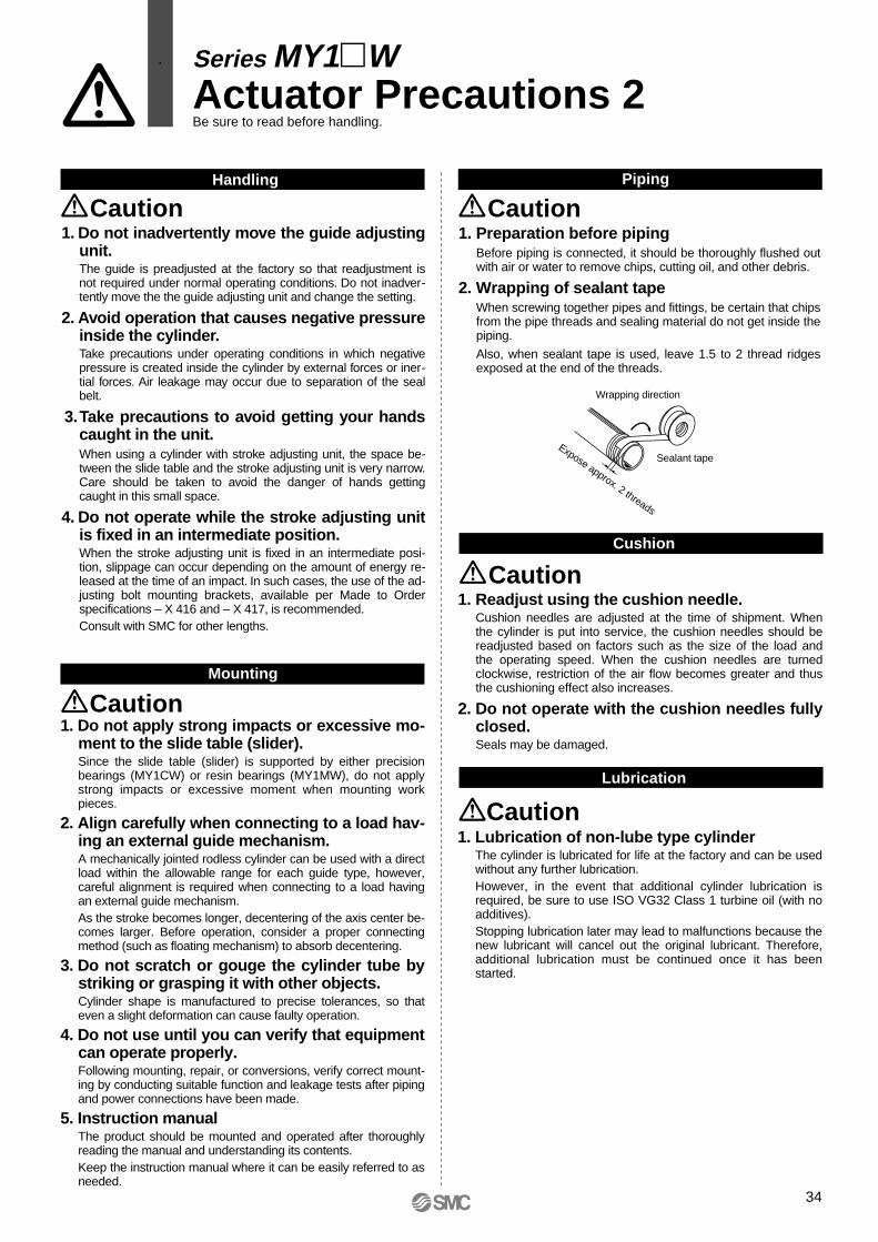
1. Do not apply strong impacts or excessive mo-ment to the slide table (slider).Since the slide table (slider) is supported by either precision bearings (MY1CW) or resin bearings (MY1MW), do not apply strong impacts or excessive moment when mounting work pieces.
2. Align carefully when connecting to a load hav-ing an external guide mechanism.A mechanically jointed rodless cylinder can be used with a direct load within the allowable range for each guide type, however, careful alignment is required when connecting to a load having an external guide mechanism.As the stroke becomes longer, decentering of the axis center be-comes larger. Before operation, consider a proper connecting method (such as floating mechanism) to absorb decentering.
3. Do not scratch or gouge the cylinder tube by striking or grasping it with other objects.Cylinder shape is manufactured to precise tolerances, so that even a slight deformation can cause faulty operation.
4. Do not use until you can verify that equipment can operate properly.Following mounting, repair, or conversions, verify correct mount-ing by conducting suitable function and leakage tests after piping and power connections have been made.
5. Instruction manualThe product should be mounted and operated after thoroughly reading the manual and understanding its contents.Keep the instruction manual where it can be easily referred to as needed.
Mounting
Caution
Piping
Caution
Cushion
Caution
Series MY1WActuator Precautions 2Be sure to read before handling.
Lubrication
Caution
Handling
1. Do not inadvertently move the guide adjusting unit.The guide is preadjusted at the factory so that readjustment is not required under normal operating conditions. Do not inadver-tently move the the guide adjusting unit and change the setting.
2. Avoid operation that causes negative pressure inside the cylinder.Take precautions under operating conditions in which negative pressure is created inside the cylinder by external forces or iner-tial forces. Air leakage may occur due to separation of the seal belt.
3. Take precautions to avoid getting your hands caught in the unit.When using a cylinder with stroke adjusting unit, the space be-tween the slide table and the stroke adjusting unit is very narrow. Care should be taken to avoid the danger of hands getting caught in this small space.
4. Do not operate while the stroke adjusting unit is fixed in an intermediate position.When the stroke adjusting unit is fixed in an intermediate posi-tion, slippage can occur depending on the amount of energy re-leased at the time of an impact. In such cases, the use of the ad-justing bolt mounting brackets, available per Made to Order specifications – X 416 and – X 417, is recommended.Consult with SMC for other lengths.
Caution1. Preparation before piping
Before piping is connected, it should be thoroughly flushed out with air or water to remove chips, cutting oil, and other debris.
2. Wrapping of sealant tapeWhen screwing together pipes and fittings, be certain that chips from the pipe threads and sealing material do not get inside the piping.
Also, when sealant tape is used, leave 1.5 to 2 thread ridges exposed at the end of the threads.
Wrapping direction
Sealant tapeExpose approx. 2 threads
1. Readjust using the cushion needle.Cushion needles are adjusted at the time of shipment. When the cylinder is put into service, the cushion needles should be readjusted based on factors such as the size of the load and the operating speed. When the cushion needles are turned clockwise, restriction of the air flow becomes greater and thus the cushioning effect also increases.
2. Do not operate with the cushion needles fully closed.Seals may be damaged.
1. Lubrication of non-lube type cylinderThe cylinder is lubricated for life at the factory and can be used without any further lubrication.However, in the event that additional cylinder lubrication is required, be sure to use ISO VG32 Class 1 turbine oil (with no additives).Stopping lubrication later may lead to malfunctions because the new lubricant will cancel out the original lubricant. Therefore, additional lubrication must be continued once it has been started.
34

Series MY1WActuator Precautions 3Be sure to read before handling.
Operating Environment
MaintenanceAir Supply
1. Use clean air.Do not use compressed air containing chemicals, synthetic oils containing organic solvents, salt, or corrosive gases, as this can cause damage or malfunctions.
1. Install air filters.Install air filters immediately upstream of valves. The filtration degree should be 5µm or finer.
2. Install an after-cooler, air dryer, or water separator (Drain Catch).Air that includes excessive drainage or condensate may cause malfunction of valves and other pneumatic equipment. To prevent this, install an after-cooler, air dryer, or water separator (Drain Catch).
3. Use the product within the specified range of fluid and ambient temperature.Take measures to prevent freezing when below 5°C, since moisture in circuits can freeze and cause damage to seals and lead to malfunctions.
Refer to SMC’s “Air Preparation System” catalog for further details on compressed air quality.
Warning
Caution
1. Perform maintenance inspection and service according to the procedures indicated in the instruction manual.Improper handling and maintenance may cause malfunctioning and damage of machinery or equipment to occur.
2. Removal of components, and supply/exhaust of compressed airBefore any machinery or equipment is removed, first ensure that the appropriate measures are in place to prevent the fall or erratic movement of driven objects and equipment, then cut off the electric power and reduce the pressure in the system to zero. Only then should you proceed with the removal of any machinery and equipment.When machinery is restarted, proceed with caution after confirming that appropriate measures are in place to prevent cylinders from lurching.
1. Filter drainageDrain out condensate from air filters regularly.
Caution
Warning
1. Do not use in environments where there is a danger of corrosion.Refer to the construction drawings to verify cylinder materials.
Warning
35

Series MY1WAuto Switch Precautions 1Be sure to read before handling.
1. Confirm the specifications.Read the specifications carefully and use the product appropri-ately. The product may be damaged or malfunction if it is used outside the range of specifications for load current, voltage, temperature, or impact.
2. Take precautions when multiple cylinders are used close together.When two or more auto switch cylinders are lined up in close proximity to each other, magnetic field interference may cause the switches to malfunction. Maintain a minimum cylinder separation of 40mm. (When the allowable interval is specified for each cylinder series, use the indicated value.)
3. Monitor the length of time that a switch is ON at an intermediate stroke position.When an auto switch is placed at an intermediate position of the stroke and a load is driven at the time the piston passes, the auto switch will operate, but if the speed is too great the operating time will be shortened and the load may not operate properly. The maximum detectable piston speed is:
4. Keep wiring as short as possible.<Reed switches>As the length of the wiring to a load gets longer, the rush current at switching ON becomes greater, and this may shorten the product’s life. (The switch will stay ON all the time.)Use a contact protection box when the wire length is 5m or longer.<Solid state switches>Although wire length should not affect switch function, use a wire that is 100m or shorter.
5. Monitor the internal voltage drop of the switch.<Reed switches>1) Switches with an indicator light (except D-A96, D-A96V, D-
Z76)• If auto switches are connected in series as shown below,
take note that there will be a large voltage drop because of internal resistance in the light emitting diodes. (Refer to internal voltage drop in the auto switch specifications.)[The voltage drop will be “n” times larger when “n” auto switches are connected.]Even though an auto switch operates normally, the load may not operate.
Design and Selection
Auto switch operating range (mm)
Load operating time (ms) x 1000V (mm/s) =
• Similarly, when operating below a specified voltage, it is possible that the load may be ineffective even though the auto switch function is normal. Therefore, the formula below should be satisfied after confirming the minimum operating voltage of the load.
2) If the internal resistance of a light emitting diode causes a problem, select a switch without an indicator light (D-A90, D-A90V, D-Z80).
<Solid state switches>3) Generally, the internal voltage drop will be greater with a 2-
wire solid state auto switch than with a reed switch. Take the same precautions as in 1) above.
Also note that a 12VDC relay is not applicable.
6. Monitor leakage current.<Solid state switches>With a 2-wire solid state auto switch, current (leakage current) flows to the load to operate the internal circuit even when in the OFF state.If the condition given in the below formula is not met, the switch will not reset correctly (it stays ON).
Use a 3-wire switch if this condition cannot be satisfied. Moreover, leakage current flow to the load will be “n” times larger when “n” auto switches are connected in parallel.
7. Do not use a load that generates surge voltage.<Reed switches>If driving a load that generates surge voltage, such as a relay, use a switch with a built-in contact protection circuit or a contact protection box. <Solid state switches>Although a zener diode for surge protection is connected at the output side of a solid state auto switch, damage may still occur if a surge is applied repeatedly. When directly driving a load that generates surge, such as a relay or solenoid valve, use a switch with a built-in surge absorbing element.
8. Cautions for use in an interlock circuitWhen an auto switch is used for an interlock signal requiring high reliability, devise a double interlock system to safeguard against malfunctions by providing a mechanical protection function, or by also using another switch (sensor) together with the auto switch. Also perform periodic maintenance inspections and confirm proper operation.
9. Ensure sufficient clearance for maintenance activities.When designing an application, be sure to allow sufficient clearance for maintenance and inspections.
Load
Warning
Minimum operatingvoltage of loadSupply voltage – >Internal voltage
drop of switch
Current to operate load (OFF condition) > Leakage current
36

Series MY1WAuto Switch Precautions 2Be sure to read before handling.
1. Do not drop or bump.Do not drop, bump, or apply excessive impacts (300m/s² or more for reed switches and 1000m/s² or more for solid state switches) while handling. Although the body of the switch may not be damaged, the inside of the switch could be damaged and cause a malfunction.
2. Do not carry a cylinder by the auto switch lead wires.Never carry a cylinder by its lead wires. This may not only cause broken lead wires, but it may cause internal elements of the switch to be damaged by the stress.
3. Mount switches using the proper tightening torque.When a switch is tightened beyond the range of tightening tor-que, the mounting screws, mounting bracket, or switch may be damaged. On the other hand, tightening below the range of tightening tor-que may allow the switch to slip out of position.
4. Mount a switch at the center of the operating range.Adjust the mounting position of an auto switch so that the pis-ton stops at the center of the operating range (the range in which a switch is ON). (The mounting positions shown in the catalog indicate the optimum position at the stroke end.) If mounted at the end of the operating range (around the border-line of ON and OFF), the operation will be unstable.
Mounting and Adjustment
Warning5. Do not allow short circuiting of loads.
<Reed switches>If the power is turned on with a load in a short circuited condition, the switch will be instantly damaged because of excess current flow into the switch.<Solid state switches>PNP output type switches do not have built-in short circuit protection circuits. If loads are short circuited, the switches will be instantly damaged, as in the case of reed switches.
∗ Take special care to avoid reverse wiring with the brown [red] power supply line and the black [white] output line on 3-wire type switches.
6. Avoid incorrect wiring.<Reed switches>A 24VDC switch with indicator light has polarity. The brown [red] lead wire is (+), and the blue [black] lead wire is (–).1) If connections are reversed, the switch will still operate, but
the light emitting diode will not light up.Also note that a current greater than the maximum specified one will damage a light emitting diode and make it inoperable.Applicable models: D-A93, D-A93V, D-Z73
<Solid state switches>1) Even if connections are reversed on a 2-wire type switch, the
switch will not be damaged because it is protected by a protection circuit, but it will remain in a normally on state. However, it is still necessary to avoid reversed connections since the switch will be damaged if a load short circuits in this condition.
∗ 2) Even if (+) and (–) power supply line connections are reversed on a 3-wire type switch, the switch will still be protected by a protection circuit. However, if the (+) power supply line is connected to the blue [black] wire and the (–) power supply line is connected to the black [white] wire, the switch will be damaged.
Wiring
1. Avoid repeatedly bending or stretching lead wires.Broken lead wires will result from repeatedly applying bending stress or stretching force to the lead wires.
2. Be sure to connect the load before power is applied.<2-wire type>If the power is turned on when an auto switch is not connected to a load, the switch will be instantly damaged because of excess current.
3. Confirm proper insulation of wiring.Be certain that there is no faulty wiring insulation (such as contact with other circuits, ground fault, improper insulation between terminals, etc.). Damage may occur due to excess current flow into a switch.
4. Do not wire in conjunction with power lines or high voltage lines.Wire separately from power lines or high voltage lines, avoiding parallel wiring or wiring in the same conduit with these lines. Control circuits containing auto switches may malfunction due to noise from these other lines.
Wiring
Warning
Warning
∗ Lead wire color changes
OldRed
Black
NewBrownBlue
Output (+)Output (–)
2-wireOldRed
BlackWhite
NewBrownBlueBlack
Power supply (+)
Power supply GNDOutput
3-wire
OldRed
BlackWhite
Yellow
NewBrownBlueBlack
Orange
Power supply (+)
Power supply GNDOutput
Diagnostic output
Solid state with diagnostic output
OldRed
BlackWhite
Yellow
NewBrownBlueBlack
Orange
Power supply (+)
Power supply GNDOutputLatch typediagnostic output
Solid state with latchtype diagnostic output
Lead wire colors of SMC switches have been changed in order to meet NECA Standard 0402 for production beginning September, 1996 and thereafter. Please refer to the tables provided.Special care should be taken regarding wire polarity during the time that the old colors still coexist with the new colors.
37

Series MY1WAuto Switch Precautions 3Be sure to read before handling.
Warning Warning
Operating Environment
1. Never use in the presence of explosive gases. The construction of our auto switches does not make them explosion proof. Never use them in the presence of an explosive gas, as this may cause a serious explosion
2. Do not use in an area where a magnetic field is generated.Auto switches will malfunction or magnets inside cylinders will become demagnetized if used in such an environment. (Consult with SMC regarding the availability of magnetic field resistant auto switches.)
3. Do not use in an environment where the auto switch will be continually exposed to water.Switches satisfy IEC standard IP67 construction (JIS C0920: watertight construction). Nevertheless, they should not be used in applications where they are continually exposed to water splash or spray. This may cause deterioration of the insulation or swelling of the potting resin inside switches and may lead to a malfunction.
4. Do not use in an environment laden with oil or chemicals.Consult with SMC if auto switches will be used in an environment laden with coolants, cleaning solvents, various oils, or chemicals. If auto switches are used under these conditions for even a short time, they may be adversely affected by a deterioration of the insulation, a malfunction due to swelling of the potting resin, or hardening of the lead wires.
5. Do not use in an environment with temperature cycles.Consult with SMC if switches are to be used where there are temperature cycles other than normal temperature changes, as they may be adversely affected internally.
6. Do not use in an environment where there is excessive impact shock.<Reed switches>When excessive impact (300m/s² or more) is applied to a reed switch during operation, the contact point may malfunction and generate or cut off a signal momentarily (1ms or less). Consult with SMC regarding the need to use a solid state switch depending on the environment.
7. Do not use in an area where surges are generated.<Solid state switch>When there are units (such as solenoid type lifters, high frequency induction furnaces, motors) that generate a large amount of surge in the area around cylinders with solid state auto switches, their proximity may cause deterioration or damage to the internal circuit elements of the switches. Avoid and protect against sources of surge generation and crossed lines.
8. Avoid close contact with accumulated iron waste or magnetic substances.When a large accumulated amount of ferrous waste such as machining chips or welding spatter, or a magnetic substance (something attracted by a magnet) is brought into close proximity to an cylinder with auto switches, this may cause the auto switches to malfunction due to a loss of the magnetic force inside the cylinder.
Maintenance
1. Perform the following maintenance inspec-tion and services periodically in order to pre-vent possible danger due to unexpected auto switch malfunction.1) Securely tighten switch mounting screws.
If screws become loose or the mounting position is dislocated, retighten screws securely after readjusting the mounting position.
2) Confirm that there is no damage to lead wires.To prevent faulty insulation, replace switches or repair lead wires if damage is discovered.
3) Confirm that the green light on the 2-color indicator type switch lights up.
Confirm that the Green LED is ON when stopped at the set position. If the Red LED is ON when stopped at the set position, the mounting position is not appropriate. Readjust the mounting position until the Green LED lights up.
Other
Warning1. Consult with SMC concerning water resist-
ance, elasticity of lead wires, and usage at welding sites.
38

Series MY1WSpecific Product Precautions 1Be sure to read before handling.Refer to pages 32 through 38 for Safety Instructions, Actuator Precautions, and Auto Switch Precautions.
1. To obtain the best results from the cover, horizontal mounting is recommended.• With horizontal mounting (shown below), the entry of dirt and
dust from the bottom of the cover is much less compared to other mounting orientations, making it much more efficient.
2. When the cylinder is mounted from the top side or when strokes are to be adjusted by installing a stroke adjusting unit, the protective cover must be removed for these purposes.• Refer to page 40 for detailed assembly procedure.
Mounting Operating Environment
Caution1. Because of floating particles such as paper
dust and coolant mist that may enter the inside of the cover.• Since there is a gap between the bottom of the cover and
cylinder tube, take precautions when operating cylinders in environments where there is exposure to excessive amount of floating particles, water/oil splash, or chip spattering. If they enter inside the cover, malfunction may occur.
Caution
Horizontal mounting
CautionCentralized Piping Port Variations• Head cover piping connection can be freely selected to best suit different piping conditions.
Applicable cylinders
MY1MW16, 20, 50, 63MY1CW16, 20, 50, 63
MY1MW25, 32, 40MY1CW25, 32, 40
Port variations
Slide table operating direction
Slide table operating direction
L
L
L
R
R
RL
R
R
RL
L
L
L
R RR
R
L LL
L
R
R
L
L
L L
LR
R
L R
L
L
R
R
L
L L
LR
LL
R
R R
R
This port is not available for use.
(except for ø50)
This port is not available for use.(except for ø32, ø40)
39

1. Component checkCheck the components.
2. Removal of coverRemove the hexagon socket head button bolts and cover.
3. Body mounting/adjustmentMount the cylinder body.For cylinders with protective cover only (i.e., without side seal), reinstall the cover after the cylinder is mounted and adjusted. (Refer to Step 6 "Cover installation".)
Series MY1WSpecific Product Precautions 2Be sure to read before handling.Refer to pages 32 through 38 for Safety Instructions, Actuator Precautions, and Auto Switch Precautions.
Assembly Procedure
4. Temporary cover installation1) Remove the hexagon socket head cap screws and one of the
end plates.2) Place the cover and temporarily secure it with the hexagon
socket button head bolts.
6. Cover installationReinstall the end plate and secure it.
5. Side seal installationSlide the side seal assembly into the place from one end of the cylinder.
Note) The end plate is installed from the bottom side of the cover. Do not move the cover upward inadvertently during end plate installation.
Note) If there is no gap (clearance) be-tween the slide table and cover (B, C in the drawing above) throughout the stroke range, loosen the hexagon socket head cap screw to readjust the cover, then retighten it.
End plate tightening torque [N⋅m]
Thread sizeM3M4M5M6M6M8M10
Bore sizeø16ø20ø25ø32ø40ø50ø63
Torque0.61.42.84.84.81224
Bore sizesø16 to ø40ø50, ø63
Torque0.61.4
Thread sizeM3M4
Cover tightening torque [N⋅m]
End plate
Hexagon sockethead button boltCover
End plate
Hexagon socket head button bolt
Stroke adjusting unit
Cover
Cylinder body
Hexagon socket head cap screw
Side seal assembly
Head cover end
Hexagon socket head cap screw
Note) Move the slide table to the end of the insertion side.
Note) Slide the side seal all the way to the end of the head cover.
Note) Make sure the side seal assembly is facing in the right direction.
Side seal assembly (applies to modelsthat come with side seal only)
Note) When auto switches are included with a cylinder order, they are packaged together with the cylinder.
Stainless steel portions of the side seal assembly are very sharp. Take extra precautions when handling.
Note) The adjustment of the stroke adjusting unit (optional) should also be done at this time.
Hexagon socket head button bolt
40
B C
Long
Sho
rt

EUROPESLOVAKIASMC Priemyselná automatizáciá, s.r.o.
SLOVENIASMC Industrijska Avtomatika d.o.o.
SPAIN/PORTUGALSMC España, S.A.
SWEDENSMC Pneumatics Sweden AB
SWITZERLANDSMC Pneumatik AG.
UKSMC Pneumatics (U.K.) Ltd.
ASIACHINASMC (China) Co., Ltd.
HONG KONGSMC Pneumatics (Hong Kong) Ltd.
INDIASMC Pneumatics (India) Pvt. Ltd.
MALAYSIASMC Malaysia (S.E.A.) Sdn. Bhd.
PHILIPPINESSMC Pneumatics (Philippines), Inc.
SINGAPORESMC Pneumatics (S.E.A.) Pte. Ltd.SOUTH KOREASMC Pneumatics Korea Co., Ltd.
TAIWANSMC Pneumatics (Taiwan) Co., Ltd.
THAILANDSMC Thailand Ltd.
NORTH AMERICACANADASMC Pneumatics (Canada) Ltd.
MEXICOSMC Corporation (Mexico) S.A. de C.V.USASMC Corporation of America
SOUTH AMERICAARGENTINASMC Argentina S.A.
BOLIVIASMC Pneumatics Bolivia S.R.L.
BRAZILSMC Pneumaticos Do Brazil Ltda.
CHILESMC Pneumatics (Chile) S.A.
VENEZUELASMC Neumatica Venezuela S.A.
OCEANIAAUSTRALIASMC Pneumatics (Australia) Pty. Ltd.
NEW ZEALANDSMC Pneumatics (N.Z.) Ltd.
EUROPEAUSTRIASMC Pneumatik GmbH
CZECHSMC Industrial Automation CZ s.r.o.
DENMARKSMC Pneumatik A/S
FINLANDSMC Pneumatics Finland Oy
FRANCESMC Pneumatique SA
GERMANYSMC Pneumatik GmbH
HUNGARYSMC Hungary Ipari Automatizálási Kft.
IRELANDSMC Pneumatics (Ireland) Ltd.
ITALYSMC Italia S.p.A.
LATVIASMC Pneumatics Latvia SIA
NETHERLANDSSMC Pnuematics BV.
NORWAYSMC Pneumatics Norway A/S
POLANDSMC Industrial Automation Polska Sp.z.o.o.
ROMANIASMC Romania s.r.l.
RUSSIA SMC Pneumatik LLC.
SMC'S GLOBAL MANUFACTURING, DISTRIBUTION AND SERVICE NETWORK
1-16-4 Shimbashi, Minato-ku, Tokyo 105-0004, JAPANTel: 03-3502-2740 Fax: 03-3508-2480URL http://www.smcworld.com© 2001 SMC CORPORATION All Rights Reserved
1st printing October, 2001 D-SMC.L.A. P-80 (D)This catalog is printed on recycled paper with concern for the global environment.
All specifications in this catalog are subject to change without notice.Printed in Japan.