mechanics and manufacturing methods
TRANSCRIPT
CHAPTER 3
MECHANICS AND MANUFACTURING METHODS
Chapter Contributors
3.1
3.1 MOTOR MANUFACTURING PROCESSFLOW*
The basic manufacturing processes for electric ac and dc motors are shown in thissection. Within each process, there are significant variables, each depending uponthe manufacturing equipment, size and variety of the parts, electrical efficiencyrequirements, and economics. Each one of these process variables is described in thefollowing text.
3.1.1 AC Motor Manufacturing Process Flow
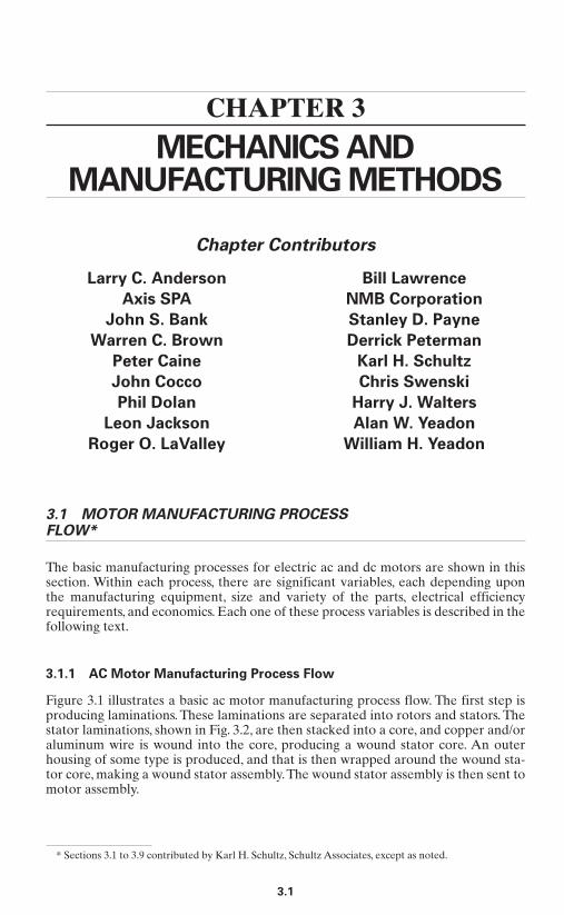
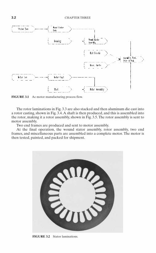
Figure 3.1 illustrates a basic ac motor manufacturing process flow. The first step isproducing laminations. These laminations are separated into rotors and stators. Thestator laminations, shown in Fig. 3.2, are then stacked into a core, and copper and/oraluminum wire is wound into the core, producing a wound stator core. An outerhousing of some type is produced, and that is then wrapped around the wound sta-tor core, making a wound stator assembly.The wound stator assembly is then sent tomotor assembly.
Larry C. Anderson
Axis SPA
John S. Bank
Warren C. Brown
Peter Caine
John Cocco
Phil Dolan
Leon Jackson
Roger O. LaValley
Bill Lawrence
NMB Corporation
Stanley D. Payne
Derrick Peterman
Karl H. Schultz
Chris Swenski
Harry J. Walters
Alan W. Yeadon
William H. Yeadon
* Sections 3.1 to 3.9 contributed by Karl H. Schultz, Schultz Associates, except as noted.
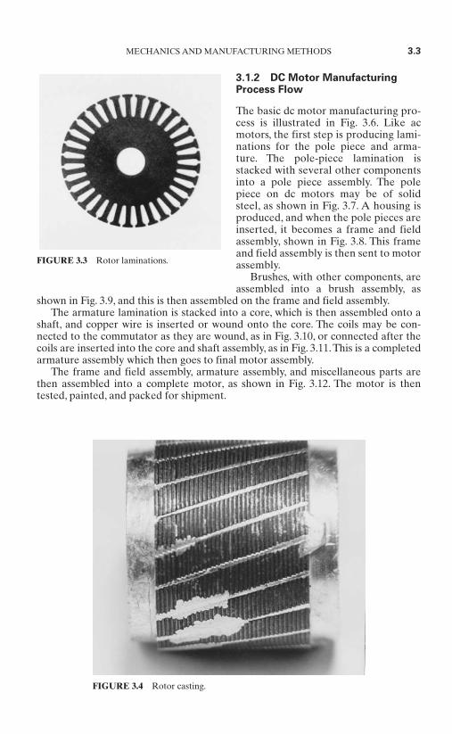
The rotor laminations in Fig. 3.3 are also stacked and then aluminum die cast intoa rotor casting, shown in Fig. 3.4.A shaft is then produced, and this is assembled intothe rotor, making it a rotor assembly, shown in Fig. 3.5. The rotor assembly is sent tomotor assembly.
Two end frames are produced and sent to motor assembly.At the final operation, the wound stator assembly, rotor assembly, two end
frames, and miscellaneous parts are assembled into a complete motor. The motor isthen tested, painted, and packed for shipment.
3.2 CHAPTER THREE
FIGURE 3.1 Ac motor manufacturing process flow.
FIGURE 3.2 Stator laminations.
3.1.2 DC Motor ManufacturingProcess Flow
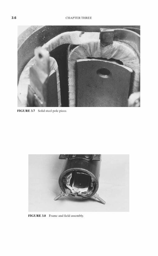
The basic dc motor manufacturing pro-cess is illustrated in Fig. 3.6. Like acmotors, the first step is producing lami-nations for the pole piece and arma-ture. The pole-piece lamination isstacked with several other componentsinto a pole piece assembly. The polepiece on dc motors may be of solidsteel, as shown in Fig. 3.7. A housing isproduced, and when the pole pieces areinserted, it becomes a frame and fieldassembly, shown in Fig. 3.8. This frameand field assembly is then sent to motorassembly.
Brushes, with other components, areassembled into a brush assembly, as
shown in Fig. 3.9, and this is then assembled on the frame and field assembly.The armature lamination is stacked into a core, which is then assembled onto a
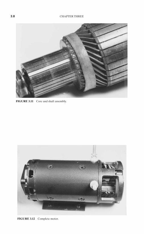
shaft, and copper wire is inserted or wound onto the core. The coils may be con-nected to the commutator as they are wound, as in Fig. 3.10, or connected after thecoils are inserted into the core and shaft assembly, as in Fig. 3.11.This is a completedarmature assembly which then goes to final motor assembly.
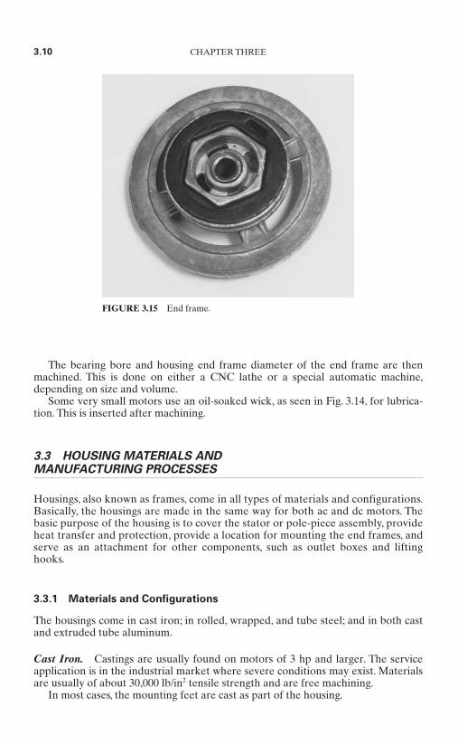
The frame and field assembly, armature assembly, and miscellaneous parts arethen assembled into a complete motor, as shown in Fig. 3.12. The motor is thentested, painted, and packed for shipment.
MECHANICS AND MANUFACTURING METHODS 3.3
FIGURE 3.3 Rotor laminations.
FIGURE 3.4 Rotor casting.

3.4 CHAPTER THREE
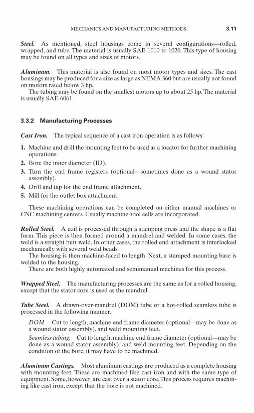
3.2 END FRAME MANUFACTURING
The basic purpose of an end frame, sometimes denoted an end bell, end shield, orbracket, is to contain the shaft bearings and support the rotor assembly. It will alsoact as a heat transfer device. On open motors, the end frame will have slots for air topass. On enclosed motors, the end frames will be solid, with no openings. A varietyof end frames are shown in Figs. 3.13, 3.14, and 3.15.
Like housings, end frames come in cast-iron, steel, zinc, or aluminum castings.Cast-iron castings are usually found on motors of 3 hp and larger. The service
application is in the industrial market where severe conditions may exist. Materialsare usually of about 30,000 lb/in2 tensile strength and are free machining.The typicalsequence of operations is a two-machine cell—a computer numerically controlled(CNC) machine prepares the bearing bore and end frame diameter, and a manualdrill is used to prepare the holes for the housing attachment.
The steel material is usually SAE 1010 to 1020. This type of end frame may befound on all types and sizes of motors.A coil is processed through a stamping press,and each part is drawn into form as a stamping. This is usually a progressive dieoperation.
A self-aligning bearing is installed and lubricant is applied. Then the bearing issized for the only machining process.
Zinc or aluminum end frames are found on most motor types and sizes and gen-erally are castings. End frames are usually cast in a horizontal die caster. Because ofits density, zinc is usually limited to end frames for motors 3 in in diameter or less. Ifthe parts are small enough, more than one part is made at one time.This depends onthe part and machine sizes. Also, on motors above 1⁄4 hp, a steel bearing insert is usu-ally die cast in the part. Following the die casting and part cooling, the part istrimmed. Many manufacturers have installed robots for this operation because ofthe heat and environmental conditions.
FIGURE 3.5 Rotor assembly.

FIGURE 3.6 DC motor manufacturing process flow.
3.5
3.6 CHAPTER THREE
FIGURE 3.7 Solid steel pole piece.
FIGURE 3.8 Frame and field assembly.

MECHANICS AND MANUFACTURING METHODS 3.7
FIGURE 3.9 Brush assembly.
FIGURE 3.10 Winding a commutator.
3.8 CHAPTER THREE
FIGURE 3.11 Core and shaft assembly.
FIGURE 3.12 Complete motor.

MECHANICS AND MANUFACTURING METHODS 3.9
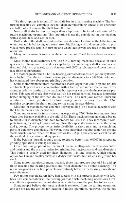
FIGURE 3.13 End frame.
FIGURE 3.14 End frame.
The bearing bore and housing end frame diameter of the end frame are thenmachined. This is done on either a CNC lathe or a special automatic machine,depending on size and volume.
Some very small motors use an oil-soaked wick, as seen in Fig. 3.14, for lubrica-tion. This is inserted after machining.
3.3 HOUSING MATERIALS ANDMANUFACTURING PROCESSES
Housings, also known as frames, come in all types of materials and configurations.Basically, the housings are made in the same way for both ac and dc motors. Thebasic purpose of the housing is to cover the stator or pole-piece assembly, provideheat transfer and protection, provide a location for mounting the end frames, andserve as an attachment for other components, such as outlet boxes and liftinghooks.
3.3.1 Materials and Configurations
The housings come in cast iron; in rolled, wrapped, and tube steel; and in both castand extruded tube aluminum.
Cast Iron. Castings are usually found on motors of 3 hp and larger. The serviceapplication is in the industrial market where severe conditions may exist. Materialsare usually of about 30,000 lb/in2 tensile strength and are free machining.
In most cases, the mounting feet are cast as part of the housing.
3.10 CHAPTER THREE
FIGURE 3.15 End frame.
Steel. As mentioned, steel housings come in several configurations—rolled,wrapped, and tube. The material is usually SAE 1010 to 1020. This type of housingmay be found on all types and sizes of motors.
Aluminum. This material is also found on most motor types and sizes. The casthousings may be produced for a size as large as NEMA 360 but are usually not foundon motors rated below 3 hp.
The tubing may be found on the smallest motors up to about 25 hp. The materialis usually SAE 6061.
3.3.2 Manufacturing Processes
Cast Iron. The typical sequence of a cast iron operation is as follows:
1. Machine and drill the mounting feet to be used as a locator for further machiningoperations.
2. Bore the inner diameter (ID).3. Turn the end frame registers (optional—sometimes done as a wound stator
assembly).4. Drill and tap for the end frame attachment.5. Mill for the outlet box attachment.
These machining operations can be completed on either manual machines orCNC machining centers. Usually machine-tool cells are incorporated.
Rolled Steel. A coil is processed through a stamping press and the shape is a flatform. This piece is then formed around a mandrel and welded. In some cases, theweld is a straight butt weld. In other cases, the rolled end attachment is interlockedmechanically with several weld beads.
The housing is then machine-faced to length. Next, a stamped mounting base iswelded to the housing.
There are both highly automated and semimanual machines for this process.
Wrapped Steel. The manufacturing processes are the same as for a rolled housing,except that the stator core is used as the mandrel.
Tube Steel. A drawn-over-mandrel (DOM) tube or a hot-rolled seamless tube isprocessed in the following manner.
DOM. Cut to length, machine end frame diameter (optional—may be done asa wound stator assembly), and weld mounting feet.Seamless tubing. Cut to length, machine end frame diameter (optional—may bedone as a wound stator assembly), and weld mounting feet. Depending on thecondition of the bore, it may have to be machined.
Aluminum Castings. Most aluminum castings are produced as a complete housingwith mounting feet. These are machined like cast iron and with the same type ofequipment. Some, however, are cast over a stator core.This process requires machin-ing like cast iron, except that the bore is not machined.
MECHANICS AND MANUFACTURING METHODS 3.11

Aluminum Tubing. The material is cut to length. Sometimes the end housingdiameter is machined prior to stator core assembly. The mounting feet are thenwelded or screwed to the housing.
3.4 SHAFT MATERIALS AND MACHINING
3.4.1 Shaft Materials
Most motor manufacturers use SAE 1045 in either cold-rolled or hot-rolled steel(CRS or HRS). Other materials include sulfurized SAE 1117, SAE 1137, SAE 1144,hot-rolled SAE 1035, and cold-rolled SAE 1018. A ground stock of any material isused on special CNC Swiss turning machines.
Generally, the cold-rolled and sulfurized steels will cost about 15 percent morethan HRS and will machine better. Machining trials need to be performed in orderto justify the extra cost. Since all shaft-turning machines perform differently, there isno established material or machining practice.
Obviously, the hot-rolled plain carbon steel, on a cost-per-pound basis, is cheaperthan cold-rolled sulfurized steel. But there are tradeoffs.The hot-rolled material hasto be sized larger than cold-rolled because of the lack of outer diameter (OD) con-trol in the rolling process. A manufacturer has to evaluate whether the larger-sizeand lower-material-cost hot-rolled bar stock is more or less costly than cold-rolledbar stock.Also, the hot-rolled material, by the very nature of its processing, has hardand soft spots, residual stresses, voids, and other material deficiencies, makingmachining more difficult. Again, machine trials need to be conducted to obtain thebest cost option between CRS, HRS, nonsulfurized, and sulfurized materials.
Because of the difficulties with HRS, most motor manufacturers will use sulfur-ized CRS.
3.4.2 Machining Operations
Most manufacturers saw, shear, or turn the shaft length off the original bar stock.Sawing is done with a band saw, machine back saw, or rotary saw, and the mate-
rial is cut either as a separate piece or in bundles.One process, to eliminate the saw-cut kerf material, is a shear cutoff process. It is
very fast and noise has been eliminated. However, this meets with mixed results. Inthe shearing process, the end of the bar is deformed—the top of it is formed down-ward and the bottom has a burr, as illustrated in Fig. 3.16.This deformation has to beremoved in the face-and-center operation, which is sometimes difficult and causesexcess tool wear.
3.12 CHAPTER THREE
burr end
FIGURE 3.16 Shear cut-off process.
The third option is to cut off the shaft bar in a bar-turning machine. The bar-turning machine will complete the shaft diameter machining, and as a last operationa cutoff tool will remove the shaft from the bar.
Nearly all shafts for motors larger than 1⁄4 hp have to be faced and centered forfuture machining operations. This operation is usually completed on one machinewith a special face-and-center tool.
Both ends of the shaft are centered to provide a tool location in the lathe turningoperation and in balancing as a rotor assembly. Facing is also done in order to pro-vide a more precise length in turning and when face drivers are used in the turningoperation.
Many motor manufacturers combine the bar cutoff and face-and-center opera-tions.
Most motor manufacturers now use CNC turning machines because of theirquick setup changeover capabilities, capability of completing a shaft in one opera-tion, and ability to precisely turn a diameter to 0.0005-in tolerance and meet the sur-face finish requirements.
On motors greater than 1⁄2 hp, the bearing journal tolerances are generally 0.0005-in or higher. The ability to turn bearing journal diameters to a 0.0005-in tolerancehas eliminated the subsequent grinding operation.
Some motor manufacturers that produce shafts larger than 2 in (3 hp and up) usea retractable jaw chuck in combination with a face driver, rather than a face driveralone, in order to maximize the machine horsepower yet provide the necessary pre-cision. This type of chuck also works well on hot-rolled bar steel because it providesbetter clamping of the bar than do face drivers. The chuck jaws retract under thesemifinish turning operation to allow turning under the jaws. Then the CNCmachine completes the finish turning to size using the face drivers.
Most motor manufacturers combine keyway milling (on a manual machine) withthe CNC lathe in a one-person cell.
Some motor manufacturers started incorporating CNC Swiss turning machineswhen they became available in the mid-1980s.These machines can machine a bar upto about 2 in in diameter and hold tolerances to 0.0003 in. They incorporate com-plete turning, including keyway milling, plus other special features such as threadingand grooving. The process helps assist flexibility in short runs and in completingparts of extensive complexity. However, these machines require centerless groundstock, which is more expensive than CRS or HRS. Again, the economics will dictatethe method of operation and equipment.
If the bearing journals require a size tolerance better than 0.0005 in, a separategrinding operation is usually required.
Other machining options are the use of manual multispindle machines for cutoffand turning and the use of grinders for grinding bearing journals and seal diameters.This option is usually used for shaft diameters 1 in and smaller. A high-volumeoption for 1-in and smaller shafts is a dedicated transfer line which uses ground barstock.
Some motor manufacturers, particularly those that produce sizes of 5 hp and up,finish-machine the bearing journals and rotor diameter as a rotor assembly. Thisoperation produces the best possible concentricity between the bearing journals androtor diameter.
Few motor manufacturers have had success with postprocess gauging with feed-back size compensation in the bearing journal finish-machining operations. How-ever, this is expensive and is not always accurate because the part has to be clean.
Some people believe that once a shaft is removed from the turning operation,one can not use the centers for location in future operations. However, the method
MECHANICS AND MANUFACTURING METHODS 3.13
used is to set up a finished shaft (with or without rotor) in a lathe to indicate thedrive end and both journals. If the output end is within 0.0005 in of true inner radius(TIR) and both journals with respect to each other are within 0.003 in TIR, turn therotor OD as is. If not, adjust centers to get the acceptable TIR.
3.5 SHAFT HARDENING
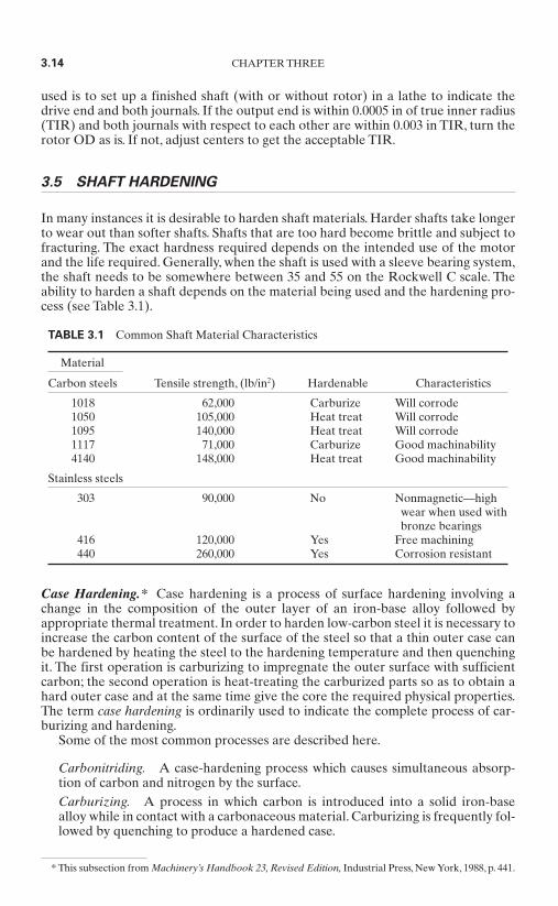
In many instances it is desirable to harden shaft materials. Harder shafts take longerto wear out than softer shafts. Shafts that are too hard become brittle and subject tofracturing. The exact hardness required depends on the intended use of the motorand the life required. Generally, when the shaft is used with a sleeve bearing system,the shaft needs to be somewhere between 35 and 55 on the Rockwell C scale. Theability to harden a shaft depends on the material being used and the hardening pro-cess (see Table 3.1).
3.14 CHAPTER THREE
TABLE 3.1 Common Shaft Material Characteristics
Material
Carbon steels Tensile strength, (lb/in2) Hardenable Characteristics
1018 62,000 Carburize Will corrode1050 105,000 Heat treat Will corrode1095 140,000 Heat treat Will corrode1117 71,000 Carburize Good machinability4140 148,000 Heat treat Good machinability
Stainless steels
303 90,000 No Nonmagnetic—highwear when used withbronze bearings
416 120,000 Yes Free machining440 260,000 Yes Corrosion resistant
Case Hardening.* Case hardening is a process of surface hardening involving achange in the composition of the outer layer of an iron-base alloy followed byappropriate thermal treatment. In order to harden low-carbon steel it is necessary toincrease the carbon content of the surface of the steel so that a thin outer case canbe hardened by heating the steel to the hardening temperature and then quenchingit. The first operation is carburizing to impregnate the outer surface with sufficientcarbon; the second operation is heat-treating the carburized parts so as to obtain ahard outer case and at the same time give the core the required physical properties.The term case hardening is ordinarily used to indicate the complete process of car-burizing and hardening.
Some of the most common processes are described here.
Carbonitriding. A case-hardening process which causes simultaneous absorp-tion of carbon and nitrogen by the surface.Carburizing. A process in which carbon is introduced into a solid iron-basealloy while in contact with a carbonaceous material. Carburizing is frequently fol-lowed by quenching to produce a hardened case.
* This subsection from Machinery’s Handbook 23, Revised Edition, Industrial Press, New York, 1988, p. 441.
Cyaniding. A process of case hardening an iron-base alloy by heating in acyanide salt.Nitriding. A process of case hardening in which an iron-base alloy of specialcomposition is heated in an atmosphere of ammonia or while in contact withnitrogenous material.
3.6 ROTOR ASSEMBLY
The rotor assembly consists of a die-cast rotor and a shaft. Both components may becompletely machined and assembled, partially machined and assembled, or a com-bination of both. The reasons for the various rotor assembly options are economics;size; unit volume; and desired electric motor efficiency, which relates to concen-tricies and the air gap between the rotor and stator.
3.6.1 Basic Assembly Process
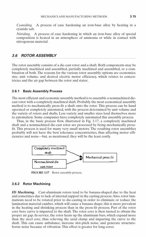
The most efficient and economic assembly method is to assemble a nonmachined die-cast rotor with a completely machined shaft. Probably the most economical assemblymethod is to mechanically press-fit a shaft onto the rotor. This process can be handoperated or completely automated, with the process determined by unit volume andthe variety of rotors and shafts. Less variety and smaller sizes lend themselves moreto automation. Some companies have completely automated this assembly process.
Thus, in the basic process flow, illustrated in Fig. 3.17, a completely machinedshaft and a nonmachined die-cast rotor are processed by being mechanically press-fit. This process is used for many very small motors. The resulting rotor assembliesprobably will not have the best tolerance concentricities, thus affecting motor effi-ciencies and noise—but, as mentioned, they will be the least costly.
3.6.2 Rotor Machining
ID Machining. Cast-aluminum rotors tend to be banana-shaped due to the heatand sometimes due to lack of internal support in the casting process.Also, rotor lam-inations need to be rotated prior to die-casting in order to eliminate or reduce thelamination material camber, which will cause a banana shape; this is more prevalentin the heating and shrinking process than in the press-fit process. Part of the rotorcore bore curve is imparted to the shaft. The rotor core is then turned to obtain theproper air gap. In service, the rotor heats up the aluminum bars, which expand morethan the steel core, thus relieving the axial clamp and imparting the curve to theshaft. This can cause unbalance, increase slot-pitch noise, and generate structure-borne noise because of vibration. This effect is greater for long cores.
MECHANICS AND MANUFACTURING METHODS 3.15
FIGURE 3.17 Rotor assembly process.

To solve this banana-shape problem, manufacturers ream, bore, or broach thecore ID prior to shaft assembly. This surface then can be used for location whenmachining the rotor OD if required.
OD Machining—Rotor OnlyTurning. Rotor OD machining is usually done on an expanding ID arbor. This
allows turning the OD to the average bore diameter. If the rotor bore is machinedprior to OD machining and used as a locator, there will be excellent concentricitybetween the bore and the OD. This possibly might eliminate machining the rotorOD when attached to the shaft, but laminations with the OD punched to size areneeded.
Grinding. Rotors that have their ODs cut with a tool will have OD smearing.This causes lamination shorting at the air gap and will reduce efficiency and causehot spots. Plunge grinding, with or without a shaft attached, will reduce smearing toa minimum. Some hermetic motor manufacturers use a centerless belt grinder tosize and clean up the OD only. Sometimes, depending upon the application, the ODwill be used as a locator to machine the ID.
OD Machining—Rotor on Shaft. There are several schools of thought on how tofinish-machine the rotor and shaft combination. One method is to allow stock on thebearing journals and then turn the rotor OD and journals in the same setup. In someCNC machines, the journals can be finished to size (not better than 0.0004 in) andfinish [20 to 30 root mean square (RMS)] without grinding. This operation can alsobe completed with a plunge grinder, but the labor content makes it expensive. Com-pleting the bearing journals and rotor OD in one setup is probably the best opera-tion for obtaining consistent air gap.
3.6.3 Electrical Efficiency Improvement Processes
Most motor manufacturers need to have better electrical efficiencies than that pro-vided by the basic assembly process (Sec. 3.6.1), and the machining processes forrotor assembly will affect the required efficiencies. This subsection examines manyof the various processes that will improve electric motor efficiencies.
Rotor Machining. Most manufacturers machine the rotor outside diameter andshaft diameters after assembly, but there are other various ways to accomplish this
process. The major interest is to achievebetter electrical efficiencies. One musthave the best concentricity between theshaft bearing diameters and the rotoroutside diameter while leaving an equalamount of back-iron thickness. Back-iron thickness is defined as the distancebetween the rotor OD, which is the lam-ination, and the aluminum die-cast slot,as shown in Fig. 3.18.
Also, there is a concern that machin-ing the rotor OD may “smear” the steel
laminations and aluminum die-cast materials. This smearing will reduce electricmotor efficiencies. In a turning operation, the cutting tools must be maintained in asharp condition.This rotor OD turning operation can be achieved as a separate partor as a rotor assembly.
3.16 CHAPTER THREE
Back-ironthickness
Slot
LaminationFIGURE 3.18 Rotor back-iron thickness.
Rotor Grinding. Another process method to reduce smearing is to use a center-less abrasive belt grinder to grind the rotor outside diameter (not as a rotor assem-bly). The abrasive belt will not become loaded up with steel and aluminum as mightoccur with a hard-wheel grinder. This centerless grinding process also guaranteesthat the back-iron thickness will be uniform.
Lamination Punching. Some motor manufacturers punch the lamination to size,thus eliminating any rotor OD turning. However, the lamination dies must be main-tained and the process monitored continuously.
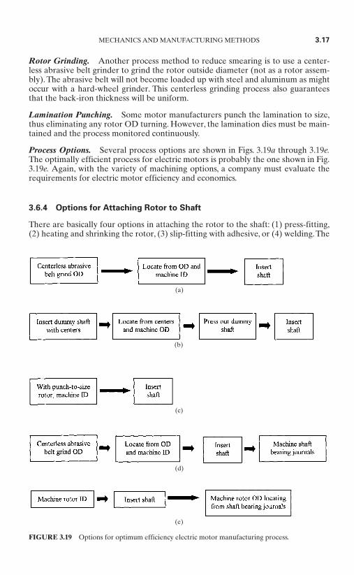
Process Options. Several process options are shown in Figs. 3.19a through 3.19e.The optimally efficient process for electric motors is probably the one shown in Fig.3.19e. Again, with the variety of machining options, a company must evaluate therequirements for electric motor efficiency and economics.
3.6.4 Options for Attaching Rotor to Shaft
There are basically four options in attaching the rotor to the shaft: (1) press-fitting,(2) heating and shrinking the rotor, (3) slip-fitting with adhesive, or (4) welding. The
MECHANICS AND MANUFACTURING METHODS 3.17
FIGURE 3.19 Options for optimum efficiency electric motor manufacturing process.
(e)
(d)
(c)
(b)
(a)

process selected is usually dictated by economics.These processes are discussed here(see Fig. 3.20).
3.18 CHAPTER THREE
FIGURE 3.20 Rotor and shaft processing option.
Press-Fitting. The most basic and economical attachment process is pressing therotor onto the shaft. This is usually done in a vertical hydraulic press. The rotor isplaced in a holding fixture, and the shaft is placed into the rotor ID. Tolerance con-trol of the rotor ID and the shaft OD must be maintained. Generally, the press fitshould be in the range of 0.001 in per inch of shaft diameter minimum.
If the press fit is too tight, the shaft may bend. If the press fit is too loose, the shaftmay turn on the rotor in application. Monitoring of the press hydraulic pressure dur-ing the press fit will provide a quality assurance check (preventing too tight or tooloose a fit).
Usually the shaft rotor diameter will be upset in some manner—knurling, jabblocking, etc.—in order to ensure a press fit.
Heating and Shrinking the Rotor. Another attachment process is heating therotor by induction or with some type of external heat source and dropping the rotor

onto the shaft.The heating process requires energy, and one must be concerned withpersonnel handling hot parts. It also requires some in-process inventory in the rotor-heating process. This process provides a greater tightness between rotor and shaftthan does press-fitting, plus it does not have the same potential for bent shafts asdoes the pressing operation.
For common shaft rotor tolerances, the rotor should be heated to between 400and 450°F (204 and 232°C), but not above 700°F (371°C), as this temperature willstart to affect the aluminum.
Generally, assembly of larger motors, over 5 hp, will use rotor heating because avery large hydraulic press is required for press-fitting.
Section 3.6.5 gives example calculations for determining shrink-fit dimensions.
Slip-Fitting with Adhesive. The rotor ID and shaft OD are sized to allow a slightslip fit of the rotor onto the shaft. It is usually on the order of 0.001 to 0.002 in ofclearance. The exact clearance is a function of the adhesive and must be adjusted inaccordance with the recommendations of the adhesive supplier. Parts must be cleanand free of lubricants before assembly.A drop or two of adhesive is put on the shaft.It is then slipped into the rotor with a twisting motion. A fixture with a stop is nec-essary for proper shaft location. After assembly, the adhesive is given time to cure.
Welding. On 5 hp and higher motors, some manufacturers weld bead the finalrotor-to-shaft attachment. Others use a key to ensure a locking condition.
Balancing. After the shaft and rotor are assembled, balancing is required. Mostbalancing operations are done by setting the rotor assembly with the bearing jour-nals on support rollers and rotating the assembly to determine the out-of-balancecondition in two planes.
There are two types of balancers, soft- and hard-bearing. Basically the differenceis that a soft-bearing machine operates below the suspension’s resonant frequency.Hard-bearing balancers are generally easier to use, safer, and provide a rigid worksupport.
Most balancing machines will determine the location and amount of weight thatneeds to be applied. Some motor manufacturers add an epoxy weight to the rotorcore. However, a fast drying heat is required in order to speed up the hardening ofthe epoxy. Others design the rotor end casts with protrusions so that weights (wash-ers) may be added.Very few drill or machine out weight because this can affect elec-trical efficiencies.
Balancing machines come in either manual- or automatic-load types, usually withcomputer controls.
3.6.5 Shrink-Fit Calculation Examples*
1. Determine the temperature differential ∆T, °F (± from room temperature).
∆T = (differential expansion)/(basic shaft diameter, in)
coefficient of thermal expansion
MECHANICS AND MANUFACTURING METHODS 3.19
* Subsection contributed by Chris Swenski, Yeadon Energy Systems, Inc.
where the differential expansion is the total diameter change required. It includesthe inference fit plus the slip clearance.
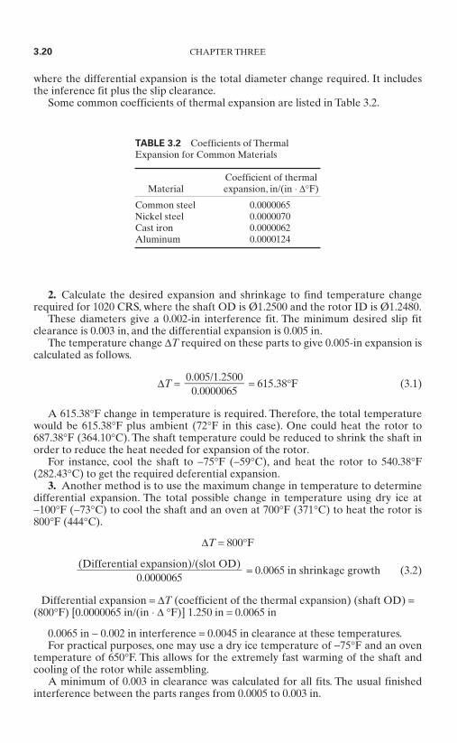
Some common coefficients of thermal expansion are listed in Table 3.2.
2. Calculate the desired expansion and shrinkage to find temperature changerequired for 1020 CRS, where the shaft OD is Ø1.2500 and the rotor ID is Ø1.2480.
These diameters give a 0.002-in interference fit. The minimum desired slip fitclearance is 0.003 in, and the differential expansion is 0.005 in.
The temperature change ∆T required on these parts to give 0.005-in expansion iscalculated as follows.
∆T = = 615.38°F (3.1)
A 615.38°F change in temperature is required. Therefore, the total temperaturewould be 615.38°F plus ambient (72°F in this case). One could heat the rotor to687.38°F (364.10°C). The shaft temperature could be reduced to shrink the shaft inorder to reduce the heat needed for expansion of the rotor.
For instance, cool the shaft to −75°F (−59°C), and heat the rotor to 540.38°F(282.43°C) to get the required deferential expansion.
3. Another method is to use the maximum change in temperature to determinedifferential expansion. The total possible change in temperature using dry ice at −100°F (−73°C) to cool the shaft and an oven at 700°F (371°C) to heat the rotor is800°F (444°C).
∆T = 800°F
= 0.0065 in shrinkage growth (3.2)
Differential expansion = ∆T (coefficient of the thermal expansion) (shaft OD) =(800°F) [0.0000065 in/(in ⋅ ∆ °F)] 1.250 in = 0.0065 in
0.0065 in − 0.002 in interference = 0.0045 in clearance at these temperatures.For practical purposes, one may use a dry ice temperature of −75°F and an oven
temperature of 650°F. This allows for the extremely fast warming of the shaft andcooling of the rotor while assembling.
A minimum of 0.003 in clearance was calculated for all fits. The usual finishedinterference between the parts ranges from 0.0005 to 0.003 in.
(Differential expansion)/(slot OD)
0.0000065
0.005/1.2500
0.0000065
3.20 CHAPTER THREE
TABLE 3.2 Coefficients of ThermalExpansion for Common Materials
Coefficient of thermal Material expansion, in/(in ⋅ ∆°F)
Common steel 0.0000065Nickel steel 0.0000070Cast iron 0.0000062Aluminum 0.0000124
3.7 WOUND STATOR ASSEMBLY PROCESSING*
Wound stator assembly processing basically consists of attaching a wound statorcore into a housing. However, there are many different assembly processes, depend-ing upon the housing material, the size, and the electrical efficiency requirements.
3.7.1 Steel Pressing
The steel housings are pressed over the wound stator core. Sometimes the mountingbase is welded or screwed to the housing before or after this operation. Usually afinal attachment is made either by welding beads or by pinning, which requiresdrilling a hole into the wound stator core.
3.7.2 Cast-Iron Pressing
The cast-iron process, for motors up to about 25 hp, is the same as that used for steelhousings, for motors above 25 hp.The housing is heated. For motors above 25 hp, thehydraulic press needed becomes very large, and the process is sometimes not eco-nomical.
3.7.3 Heating and Shrinking
Almost all aluminum housings are heated and shrunk onto the wound stator core.Usually, the housings are pinned to the wound stator core. The base is sometimeswelded or screwed to the housing before or after this operation.
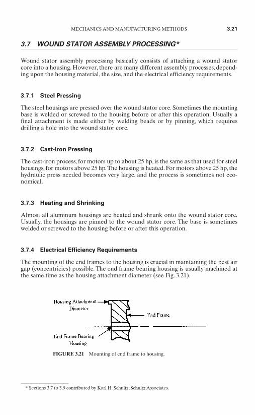
3.7.4 Electrical Efficiency Requirements
The mounting of the end frames to the housing is crucial in maintaining the best airgap (concentricies) possible. The end frame bearing housing is usually machined atthe same time as the housing attachment diameter (see Fig. 3.21).
MECHANICS AND MANUFACTURING METHODS 3.21
* Sections 3.7 to 3.9 contributed by Karl H. Schultz, Schultz Associates.
FIGURE 3.21 Mounting of end frame to housing.
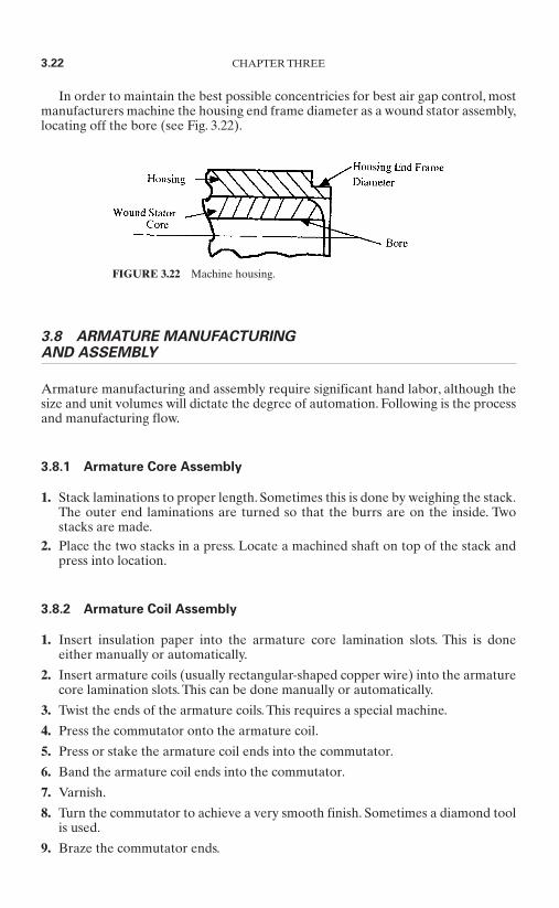
In order to maintain the best possible concentricies for best air gap control, mostmanufacturers machine the housing end frame diameter as a wound stator assembly,locating off the bore (see Fig. 3.22).
3.8 ARMATURE MANUFACTURING AND ASSEMBLY
Armature manufacturing and assembly require significant hand labor, although thesize and unit volumes will dictate the degree of automation. Following is the processand manufacturing flow.
3.8.1 Armature Core Assembly
1. Stack laminations to proper length. Sometimes this is done by weighing the stack.The outer end laminations are turned so that the burrs are on the inside. Twostacks are made.
2. Place the two stacks in a press. Locate a machined shaft on top of the stack andpress into location.
3.8.2 Armature Coil Assembly
1. Insert insulation paper into the armature core lamination slots. This is doneeither manually or automatically.
2. Insert armature coils (usually rectangular-shaped copper wire) into the armaturecore lamination slots. This can be done manually or automatically.
3. Twist the ends of the armature coils. This requires a special machine.
4. Press the commutator onto the armature coil.
5. Press or stake the armature coil ends into the commutator.
6. Band the armature coil ends into the commutator.
7. Varnish.
8. Turn the commutator to achieve a very smooth finish. Sometimes a diamond toolis used.
9. Braze the commutator ends.
3.22 CHAPTER THREE
FIGURE 3.22 Machine housing.
3.9 ASSEMBLY, TESTING, PAINTING, AND PACKING
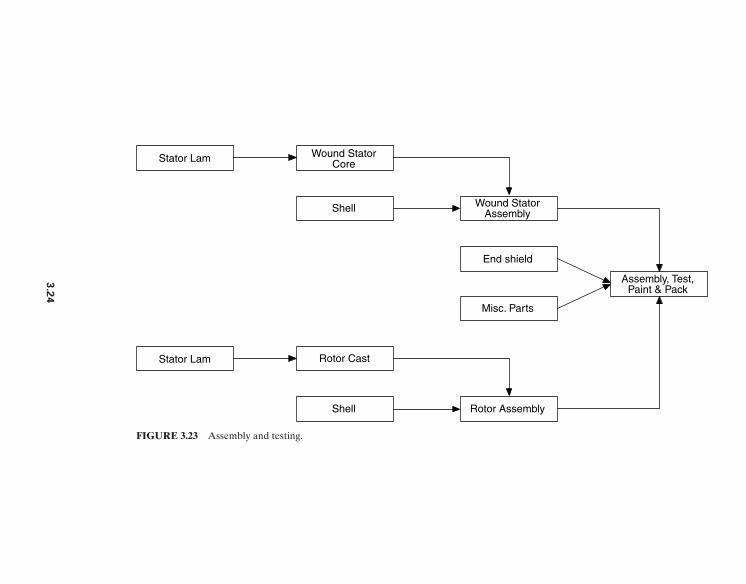
The final motor assembly, testing, painting, and packing process is as varied as theother processes, depending upon the unit volume, size, and variety (see Fig. 3.23).
3.9.1 Assembly
Most very small motors up to about 1⁄4 hp can be assembled automatically. Some areassembled in as little as 5 s by highly automated equipment costing hundreds ofthousands of dollars. The success of high-volume automation is the quality of theparts. Part quality that can not be controlled will jam the machine and cause poorutilization.
Changeover from one motor size or configuration to another is not easily doneon a high-volume automated machine, although there have been strides in recentyears to provide for quick setup. High-volume automated assembly machines arebest run without changeover because they need to be kept running as much as pos-sible in order to justify their cost.
In a line loader, the operator gathers various parts needed to assemble a particu-lar motor (end frames, rotor assembly, wound stator assembly, and miscellaneousparts) and places them on a tray, which moves down a conveyor to the assembly line.
The conveyor to the assembly line is controlled by an assembly operator, so themotor parts may be called for as they are needed.
There are several assembly stations, and each operator takes parts from the trayand completes their portion of the assembly. The operator then places that compo-nent on the tray, and it moves to the next station. Sometimes this process is done ona moving conveyor rather than trays.
Some low-volume or significantly sized motors are assembled in one-person cells.The components are set on pallets and/or in racks for the assembly operator’s access.Usually the operator will assemble the complete motor.
3.9.2 Testing
A variety of electrical and mechanical tests are usually completed on a motor beforeshipping, some dictated by customer requirements. These tests can be any or all ofthe following: input voltage regulation, full load, no load, inertial load, equivalentcircuit, locked rotor, low-voltage start, torque/speed curve, rotation direction, ac ordc high potential, insulation resistance, surge/impulse, vibration, acoustic noise, andtemperature. Most test systems have preprogrammed menus so that the operatordoes not need to input the data.
After the initial setup, the operator loads and secures the motor into the fixture,makes the proper connections, and starts the test. All testing is automaticallysequenced. After the test is completed, the measured results are compared to pre-programmed limits. The data is stored, printed, or transmitted as the user requires.The operator can observe whether the motor has passed or failed and can takeappropriate action. Manual to completely automatic test equipment is available.
Sometimes mechanical tests are performed, such as for rotor assembly end playand tight bearings. Noise tests are also conducted, and most motor manufacturersenclose the entire test area in a sound booth so that any noise can be measured orheard.
MECHANICS AND MANUFACTURING METHODS 3.23
Stator Lam Wound StatorCore
Wound StatorAssembly
Assembly, Test,Paint & Pack
Shell
Stator Lam Rotor Cast
Rotor AssemblyShell
End shield
Misc. Parts
FIGURE 3.23 Assembly and testing.
3.2
4
3.9.3 Painting
Environmental regulations have largely restricted the type of paint that can be used.Most manufacturers have changed to a water-base or powder paint and have auto-mated the process. Meeting customer color requirements requires motor manufac-turers to install equipment that can be quickly changed over.
Some manufacturers paint components before assembly to eliminate masking.However, the components have to be handled properly in order to minimize mark-ing at assembly.
3.9.4 Packing
Motors under 1⁄4 hp are usually shrink-wrapped separately. Some have cardboardbases for support. Some are put on a pallet and shrink-wrapped as a container.Motors over 1⁄4 hp are usually packed in cardboard boxes or on pallets. Most of thepackaging process can be automated as much as possible.
3.10 MAGNETIC CORES*
Stator core assemblies, shown in Figs. 3.24 and 3.25, are insulated stacks of lamina-tions lined up to close tolerances. The laminations themselves can be held to toler-ances within 0.001 in (±0.0005 in) on the OD and ID. However, they must beassembled into a core in some fashion. Permanent-magnet motors have air gaps onthe order of 0.015 to 0.040 in per side. Induction motors have air gaps on the orderof 0.010 to 0.015 in. These gaps must be held very consistent to avoid performanceand noise degradation. There are many methods for assembling stacks of lamina-tions. This section discusses some of the most common stacking methods with theirpositive and negative attributes.
Loose armature, induction rotor, or outer rotor brushless dc motor laminationsmay be pressed onto a sleeve or shaft. Other methods include heat shrinking, ringstaking, or adhesive bonding.
3.10.1 Welded Cores
The lamination stacks are generally fixtured off the stator bore and welded alongthe OD of the stack. The tolerance is now a result of the welding fixture, whichallows for some shift in lamination placement. The eddy current core losses areincreased because the welding short-circuits to the laminations at the weld joints.The core assembly may have to be machined to bring the OD back to an acceptabledimension. Weld depth should be kept to a minimum, and welds should be posi-tioned behind the poles or teeth. When possible, a laser weld is best in the cases inwhich it provides adequate strength.
MECHANICS AND MANUFACTURING METHODS 3.25
* Sections 3.10 to 3.10.3 contributed by William H.Yeadon and Alan W.Yeadon,Yeadon Engineering Ser-vices, PC.

3.10.2 Bonded Cores
These cores are built by coating the laminations with an adhesive, aligning them ona fixture, and heating the cores to set up the adhesive. Here the tolerances are a func-tion of the fixture tooling, and the OD may have to be machined to get it to anacceptable dimension. If anything, the adhesive assists in reducing eddy currentlosses; however, it takes up space, and the effective core length may be somewhatless than expected.
3.26 CHAPTER THREE
FIGURE 3.24 Outer rotor brushless dc stator core assembly (FEMD).
FIGURE 3.25 Inner rotor brushless dc stator core assembly.
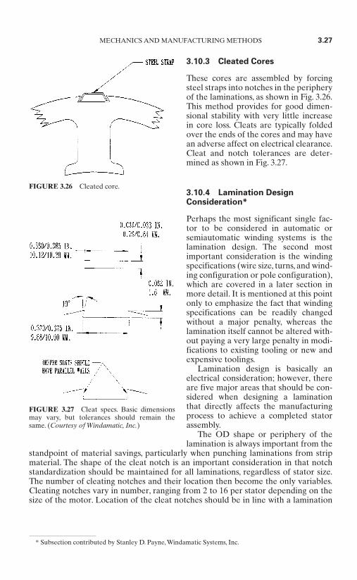
3.10.3 Cleated Cores
These cores are assembled by forcingsteel straps into notches in the peripheryof the laminations, as shown in Fig. 3.26.This method provides for good dimen-sional stability with very little increasein core loss. Cleats are typically foldedover the ends of the cores and may havean adverse affect on electrical clearance.Cleat and notch tolerances are deter-mined as shown in Fig. 3.27.
3.10.4 Lamination DesignConsideration*
Perhaps the most significant single fac-tor to be considered in automatic orsemiautomatic winding systems is thelamination design. The second mostimportant consideration is the windingspecifications (wire size, turns, and wind-ing configuration or pole configuration),which are covered in a later section inmore detail. It is mentioned at this pointonly to emphasize the fact that windingspecifications can be readily changedwithout a major penalty, whereas thelamination itself cannot be altered with-out paying a very large penalty in modi-fications to existing tooling or new andexpensive toolings.
Lamination design is basically anelectrical consideration; however, thereare five major areas that should be con-sidered when designing a laminationthat directly affects the manufacturingprocess to achieve a completed statorassembly.
The OD shape or periphery of thelamination is always important from the
standpoint of material savings, particularly when punching laminations from stripmaterial. The shape of the cleat notch is an important consideration in that notchstandardization should be maintained for all laminations, regardless of stator size.The number of cleating notches and their location then become the only variables.Cleating notches vary in number, ranging from 2 to 16 per stator depending on thesize of the motor. Location of the cleat notches should be in line with a lamination
MECHANICS AND MANUFACTURING METHODS 3.27
* Subsection contributed by Stanley D. Payne, Windamatic Systems, Inc.
FIGURE 3.26 Cleated core.
FIGURE 3.27 Cleat specs. Basic dimensionsmay vary, but tolerances should remain thesame. (Courtesy of Windamatic, Inc.)
tooth or slot opening, with lamination tooth alignment being preferable. On largestators having many cleats, it is essential that they be equally spaced about theperiphery of the stator and always be two notches, 180°, apart.
It is always desirable to have the largest possible slot opening in a lamination;however, this can sometimes be in direct opposition to the desires of the designerfrom an efficiency standpoint and sometimes to considerations of noise in the finalproduct. Hence, final selection of slot openings is always a compromise between theproduct parameters and the restrictions imposed on the manufacturing process. Inthe past, when hand winding was the only manufacturing process, the major consid-eration was the stiffness of the wire. Usually 17 AWG was considered the practicalmaximum wire size from an operator’s standpoint.
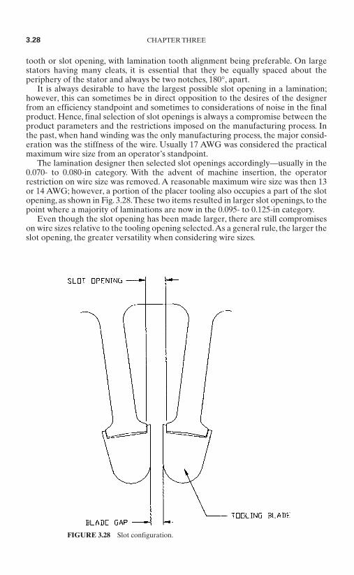
The lamination designer then selected slot openings accordingly—usually in the0.070- to 0.080-in category. With the advent of machine insertion, the operatorrestriction on wire size was removed. A reasonable maximum wire size was then 13or 14 AWG; however, a portion of the placer tooling also occupies a part of the slotopening, as shown in Fig. 3.28.These two items resulted in larger slot openings, to thepoint where a majority of laminations are now in the 0.095- to 0.125-in category.
Even though the slot opening has been made larger, there are still compromiseson wire sizes relative to the tooling opening selected.As a general rule, the larger theslot opening, the greater versatility when considering wire sizes.
3.28 CHAPTER THREE
FIGURE 3.28 Slot configuration.
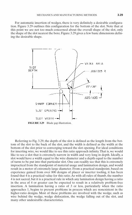
For automatic insertion of wedges, there is very definitely a desirable configura-tion. Figure 3.29 outlines this configuration for the bottom of the slot. Note that atthis point we are not too much concerned about the overall shape of the slot, onlythe shape of the slot nearest the bore. Figure 3.29 gives a few basic dimensions defin-ing the desirable shape.
Referring to Fig. 3.29, the depth of the slot is defined as the length from the bot-tom of the slot to the back of the slot, and the width is defined as the width at thebottom of the slot prior to converging toward the slot opening. For ideal conditionsfor inserting wire, we would like to see this ratio approach infinity. That is, we wouldlike to see a slot that is extremely narrow in width and very long in depth. Ideally, aslot would have a width equal to the wire diameter and a depth equal to the numberof turns to be put into that particular slot. One can readily see that this is extremelyimpractical from the standpoint of material usage and lamination design, and wouldresult in a motor of extremely large diameter. From a practical standpoint, based onexperience gained from over 800 designs of placer or inserter tooling, it has beenfound that 4 is a practical value for this ratio. As with all rules of thumb, the number4 is not sacred, but it is a practical rule in which any lamination design having a ratioin the area of 4 or greater can be expected to result in a relatively problem-freeinsertion. A lamination having a ratio of 3 or less, particularly when the ratioapproaches 1, begins to present problems in process which are nonexistent in thehigher-ratio designs. Most of these problems are involved with the wedge, such aswire behind the wedge, wedge dislocation, the wedge falling out of the slot, andmany other undesirable characteristics.
MECHANICS AND MANUFACTURING METHODS 3.29
FIGURE 3.29 Blade gap illustration.

The shape of the back of the slot is not crucial for most practical purposes. It isgenerally found in two basic configurations, a square bottom and a round bottom.The round bottom is the preferred shape due to the simplification of tooling.
The present basic practice in lamination design is to consider what is the bestlamination design in order to obtain the desired electrical characteristics or perfor-mance of the motor. From an electrical and mechanical standpoint, there are someareas that must be different within a family of laminations which are important tothe performance of the final product, such as having 24 slots for a 2-pole motor and36 slots for a 6-pole motor. However, there are also certain other areas that can bestandardized or grouped within a family of laminations, such as having two 36-slot 6-pole laminations, one for copper and one for aluminum windings, which differ onlyin the slot detail. Standardization of the slot opening and wedge area or base of theslot can result in identical placer toolings even though the laminations are not iden-tical in all other respects.
The grouping of the family of laminations should begin with the bore, then fur-ther subdividing common bores into groups having the same number of slots. Exam-ination of the laminations within the same subgroup will then show that there areusually very small differences in the significant areas, as previously mentioned—forexample, the slot opening and the wedge entry area. Usually these small variationscan be eliminated with little effect on the electrical performance of the final prod-ucts. Standardization of laminations therefore can significantly reduce product coststhrough standardization of toolings, increased machine utilization, and reducedlabor by eliminating tool changeovers.
Winding Specifications. Winding specifications—for example, wire size, numberof turns, and pole configurations—are the second most crucial criteria, as men-tioned previously for automatic or machine insertion of stators. Compatibility ofthe selected tooling opening, or blade gap, which is dependent on the slot openingand the wire size to be used, is essential. However, unlike lamination changes, wiresizes and numbers of turns can be varied to a certain degree without incurring thepenalties of major costs or degraded product performance. As mentioned in theprevious subsection, the larger the slot opening, the greater the versatility in wire-size selection.
The slot opening versus wire size situation can be best explained by the chartshown in Fig. 3.30, where the advantages and disadvantages become apparent.
There is an area on the chart that represents the locking-wire condition in whichtwo wires attempting to pass one another lock. This condition can generate lockingforces which can damage wire insulation, actually stall the insertion process, and insome cases cause tooling damage. The total locking force generated in the lockingarea depends on the number of turns (conductors) being inserted. Obviously, 1 turncannot lock, 2 turns generates a small force, and a large number of turns, such as 50,generates a large force.
Empirical conclusions based on a large number of tooling designs and conditionsindicate that, in general, a maximum turn count of 20 can be inserted per slot in thelocking area without damage to wire or tooling.
The area between the locking-wire area and the maximum-wire-size curve isreferred to as the precision wind area, so called as the wire must be in a single-layeror precision condition. This area also presents some restrictions on the number ofturns due to column height and a condition similar to the previously mentioned lock-ing situation. Usually, 35 turns for standard placer tooling and 50 to 55 turns withspecial tooling options are considered safe selections. Higher turn counts can resultin wire damage and can involve extensive tooling development programs.
3.30 CHAPTER THREE

The area below the locking area represents the level wind area and is consideredthe ideal situation for coil insertion. Slot fullness is usually the limiting condition forthis area, except for special slot configurations. Anything below 70 percent is con-sidered good, with 76 percent a practical maximum for standard toolings. Furtherdiscussion concerning slot fullness is covered in a later section.
Many developments in tooling design and special features have improved theserestrictions and the quality obtained, but have not entirely eliminated them.
Once the wire has been inserted into the stator, the major material costs havebeen incurred and the basic quality of the stator assembly has been determinedexcept for lead connecting. Compatibility of the slot opening and the wire size there-fore becomes a major contributing factor to cost, through high or low scrap rates,which directly reflect the difficulty or ease of the manufacturing process and thefinal quality of the stator.
Pole Configuration. Pole configuration usually refers to the number of poles andthe physical shape and location within a stator. There exist two major categories ofpole configuration, lap winding and concentric.
The coil-insertion process has almost eliminated lap-type windings.Although it ispossible to insert some lap windings, it is almost impossible to achieve the slot fillsand production rates of equivalent concentric windings. Almost all of the lap-typemotors, probably 90 to 95 percent, are hand wound.
This section therefore deals only with the single-phase and three-phase concentric-type windings.The vast majority of the single-phase motors produced today follow astandard two-, four-, or six-pole configuration, varying only in the number of con-centric coils per pole, which is limited, and slot fullness. The tendency today is forhigher slot fills, which in a single-phase motor are much more difficult to achievethan in a three-phase motor due to the nature of the main winding.
MECHANICS AND MANUFACTURING METHODS 3.31
FIGURE 3.30 Blade gap chart. Note that allowance must be made for stack (core) skew or stag-ger. Maximum blade gap = iron gap − 0.030 in (0.8 mm).
Three-phase motors present a much greater opportunity for variation in poleconfiguration. The industry standard has been the three-layer uniform design, hav-ing no shared or some shared slots, which is accomplished by varying the number ofconcentric coils per pole. In the past, some manufacturers have used a two-coil-sides-per-slot design in which all slots are shared, but this has not yet proven to be apopular approach.
The two-pole three-phase motors are fairly straightforward in a three-layerdesign, with some or all slots shared. This is fairly well limited due to the physicalconfiguration inherent in a two-pole design.
The four-pole three-phase motors present a high degree of variation; however,the majority of the stators produced today are of the standard three-layer four-pole-per-layer uniform design. One fairly popular design is the European or conse-quent pole design. The main reason is that the 2-layer three-pole-per-layerconfiguration, usually in a nonsharing slot condition, requires only two insertions tocomplete the motor. Winding time is less to generate 6 total coils for a completemotor, rather than the normal 12 poles. Phase insulation for this type of motor ismuch simpler due to having only two layers, instead of three, and in some cases iseliminated.
However, there are some disadvantages. It is usually considered to be a less effi-cient motor, it requires more interpole or lead connections, and, finally, it has beenknown to require more copper than the three-layer design.
The six-pole three-phase motor also presents the same type of variations as thefour-pole, but perhaps to a lesser degree. A six-pole European or consequent designis also used, but is less popular. The same basic criteria exists as in the four-pole, twoinsertions instead of three, and in this case 9 poles rather than the normal 18. Someof the same disadvantages also exist as for the four-pole.
The standard three-layer designs for two-, four-, and six-poles can be produced ina gradient design. The gradient design is achieved by decreasing the circumferenceof the pole for each succeeding phase or layer. The first layer or phase insertedwould be the longest, the second slightly smaller, and the third slightly smaller yet.The net result is a savings in wire and better nesting of the end turns. This type ofdesign is generally considered to be an imbalanced-phase winding and could have anegative effect on the performance. However, if properly designed, the advantagescan outweigh the performance disadvantages.
Although gradient design is not generally used across the industry, the more pro-gressive manufacturers are using this approach or looking at it very seriously. It isbeginning to appear as an approach that could become standard practice in thefuture.
Slot Fill. Slot fill is usually given as a percentage figure that expresses the amountof wire in a slot in relation to the total slot area. Unfortunately, there are severalmethods presently in use for calculating slot fill.
Widely varying slot-fill percentages can be obtained for the same situationdepending on the method used. Two general methods are circular mils and squarewire. Electrical designers would normally use the circular-mil method becausethey are more interested in the actual cross section of the conductor. Process engineers or equipment suppliers would be more apt to use the square-wiremethod, which more nearly reflects the actual conditions with which they mustwork.
Variations within each of these basic methods will also occur depending on themethod used to determine the slot area. The insulation in the slot—for example, theslot cell and wedge—will occupy a portion of the slot area.
3.32 CHAPTER THREE
Some calculations will take into consideration the slot insulation, while otherswill ignore it. Taking into consideration the slot insulation results in an available slotarea.
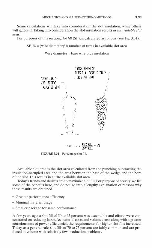
For purposes of this section, slot fill (SF), is calculated as follows (see Fig. 3.31):
SF, % = (wire diameter)2 × number of turns in available slot area
Wire diameter = bare wire plus insulation
Available slot area is the slot area calculated from the punching, subtracting theinsulation-occupied area and the area between the base of the wedge and the boreof the slot. This results in a true available slot area.
Today’s trends and desires are to maximize slot fill. For purpose of brevity, we listsome of the benefits here, and do not go into a lengthy explanation of reasons whythese results are obtained.
Greater performance efficiency Minimal material usage Smaller package for same performance
A few years ago, a slot fill of 50 to 65 percent was acceptable and efforts were con-centrated on reducing labor.As material costs and volumes rose along with a greaterconsciousness of power efficiencies, the requirements for higher slot fills increased.Today, as a general rule, slot fills of 70 to 75 percent are fairly common and are pro-duced in volume with relatively few production problems.
MECHANICS AND MANUFACTURING METHODS 3.33
FIGURE 3.31 Percentage slot fill.
In some cases, slot fills of 80 to 81 percent have been achieved, but to do thisrequires special development and a concentrated effort in tailoring toolings for aparticular application.
The desire for high slot fills is very great at the present time, and there are severaltheories or approaches under consideration which have not been developed, as yet,into practical production methods.
One area of effort is to develop a slot shape which approaches the ideal slot. Asmentioned previously, the more nearly ideal slot from a production viewpointinvolves a compromise of a larger-OD stator and therefore is less attractive thanother approaches.
Perhaps the most attractive and promising approach is the compaction process.This process is exactly as its name implies—compacting the wires in the slot. Somemanufacturers have taken tentative steps in this direction.
The theory is very simple and consists of inserting a first layer of wire into a slot,compacting or deforming the wires into the back of the slot to fill all of the voidspaces between wires, then inserting a second layer of wire.As a simplified example,if a 92 percent slot fill is desired, a first insertion of 46 percent or half the total wiresis inserted. By the process of compaction, these wires are then forced to occupy only40 percent of the slot. The remainder of the slot, 60 percent, is now available for thenext insertion of 46 percent of the wire, which results in a 76 percent slot-fill inser-tion attempt on the second pass. The second insertion falls within the range of feasi-bility based on present practice.
The use of the General Electric Electro-press process could also contribute to thefeasibility of achieving the desired results or increasing the total percentage slightly.This can be accomplished by taking advantage of the fact that the Electro-press pro-cess has a tendency to straighten wires, eliminating the crossing in the slot that occu-pies additional space. Straightening of the wires prior to compaction wouldtherefore assist in achieving higher slot fills.
The compaction and Electro-press slot-development approach should make slotfills in the 90 percent range accessible.
Phase Insulation. From a labor and materials standpoint, phase insulation is per-haps one of the most difficult, time-consuming, and expensive areas of stator manu-facture. Phase insulation can be accomplished through several different methods.The main object of this particular section is to recommend the type of phase insu-lation and the point in the assembly line where phase insulation is to be installed.This assumes that phase insulation is required.A major savings can be accomplishedif phase insulation is eliminated. Some motor manufacturers have eliminated this type of insulation, but not without some problems. For the most part, theyhave been successful. Unfortunately, at this time, the manufacturers who haveeliminated phase insulation are in the minority. It has always been felt that phaseinsulation is required in order to guarantee a quality product and is an insurancepolicy of sorts. However, with today’s improvements in wire insulation, slot-cellinsulation, and manufacturing methods, the whole area of phase insulation should be very seriously considered for potential cost reduction.We would recommend thata program be instituted to investigate the possibility of the elimination of phaseinsulation.
At the present time, various methods of phase insulation are being used. One ofthe most popular is the H-type paper insulation, which must be installed betweenthe layers or phases of windings during the process of winding the stator. Thisinvolves winding one layer of the stator, hand-inserting the H-type paper insulation,and then winding the next layer of wire into the stator. In three-phase stators, one
3.34 CHAPTER THREE
more layer is yet to be inserted; therefore, a second hand insertion of phase papermust be undertaken, and then the third and final layer of winding is inserted into thestator. This is at best a slow operation and also very labor intensive, not to mentionthat the H paper is generally made of a polyester-type material with very high scraprates.
A second method is to insert the first layer and then proceed by hand to add anadhesive tape to the end turns which acts as a phase insulation. The second layer isthen inserted and has to be taped by hand prior to the insertion of the third layer.This is also a labor-intensive operation and requires special materials which some-times are not compatible with the products being manufactured (for example, theadhesive tape).
The third method, the method which we prefer, is an operation in which allthree layers (three-phase) or two layers (one-phase) of the motor are inserted in acontinuous flow operation without interruption for phase insulation. A variable-wedge-length device is included on the equipment for notching wedges. In the end,the wedges constitute a part of the phase insulation. After the stator winding is completed, phase insulation is added into and between the end turns of the wire as required. This material can be of the same polyester as is used in the Hpaper; however, it is merely a strip of material, and scrap is virtually eliminatedexcept for rounding some corners. There are several advantages to using thismethod:
The winding operation is not interrupted. The equipment is not idle during phase insulation, and no unloading and reload-
ing of the stator into the insertion flow system is required. The elimination of polyester scrap is an obvious cost savings.
The time required to insert the phase insulation is substantially less than thatrequired for either of the first two methods.
There are some disadvantages to this method, one of which is that it must be a hand operation. Second, it requires some manipulation of the end turns with a hand tool in order to separate the windings where the insulation is to beinserted, which could possibly result in a deterioration of the quality. However,this type of process has been and is being used successfully in some major motor plants around the country. In conclusion, the best approach to phase insula-tion is to eliminate phase insulation. If this cannot be accomplished, then the sec-ond best is to automatically machine-insert phase insulation. However, at thepresent time this type of equipment is not yet very popular. In the interim, the process that is best utilized for minimizing cost is the hand insertion of polyestersegments into the end turn at a station away from the winding and insertion of the stator.
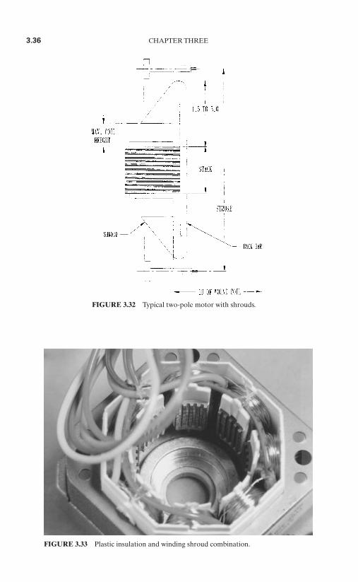
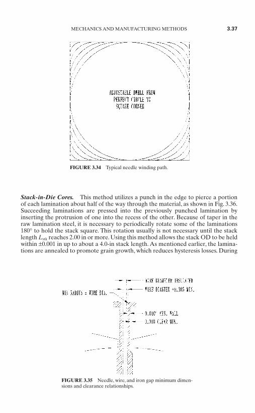
Salient Pole Motors. Salient pole machines like universal motor fields, shaded-pole motor stators, and stepper motor stators are usually needle- or gun-wound.They may be wound with shroud tooling, as shown in Fig. 3.32, or they may be wounddirectly on molded plastic insulation which also serves as tooling, as shown in Fig.3.33. In these cases, the minimum slot opening must take the needle size and pathinto account. The typical needle path is shown in Fig. 3.34. The slot opening mustallow for this movement plus some clearance. The slot opening is determined as fol-lows. Select the maximum coated wire diameter that will be used in the intendedapplication. Next, determine the minimum allowable needle bore, outside dimen-sions, and clearances per Fig. 3.35.
MECHANICS AND MANUFACTURING METHODS 3.35
3.36 CHAPTER THREE
FIGURE 3.32 Typical two-pole motor with shrouds.
FIGURE 3.33 Plastic insulation and winding shroud combination.
Stack-in-Die Cores. This method utilizes a punch in the edge to pierce a portionof each lamination about half of the way through the material, as shown in Fig. 3.36.Succeeding laminations are pressed into the previously punched lamination byinserting the protrusion of one into the recess of the other. Because of taper in theraw lamination steel, it is necessary to periodically rotate some of the laminations180° to hold the stack square. This rotation usually is not necessary until the stacklength Lstk reaches 2.00 in or more. Using this method allows the stack OD to be heldwithin ±0.001 in up to about a 4.0-in stack length. As mentioned earlier, the lamina-tions are annealed to promote grain growth, which reduces hysteresis losses. During
MECHANICS AND MANUFACTURING METHODS 3.37
FIGURE 3.34 Typical needle winding path.
FIGURE 3.35 Needle, wire, and iron gap minimum dimen-sions and clearance relationships.
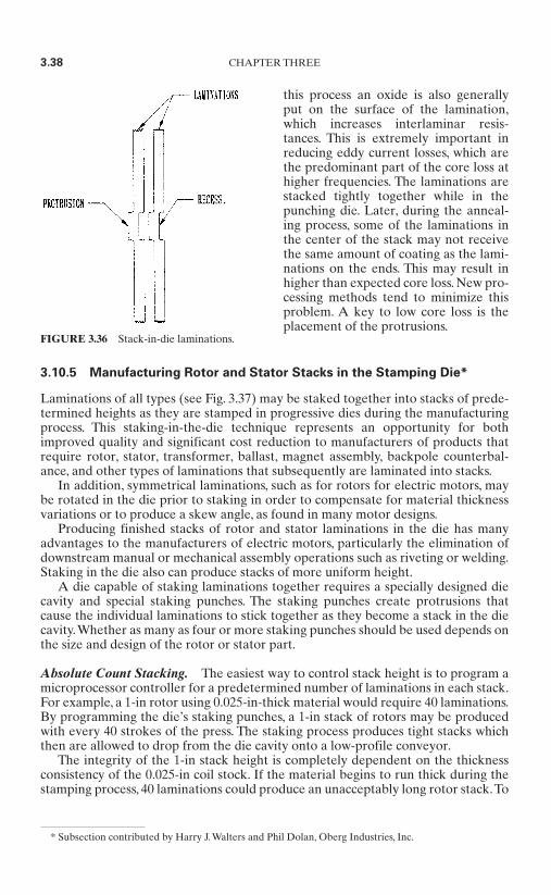
this process an oxide is also generallyput on the surface of the lamination,which increases interlaminar resis-tances. This is extremely important inreducing eddy current losses, which arethe predominant part of the core loss athigher frequencies. The laminations arestacked tightly together while in thepunching die. Later, during the anneal-ing process, some of the laminations inthe center of the stack may not receivethe same amount of coating as the lami-nations on the ends. This may result inhigher than expected core loss. New pro-cessing methods tend to minimize thisproblem. A key to low core loss is theplacement of the protrusions.
3.10.5 Manufacturing Rotor and Stator Stacks in the Stamping Die*
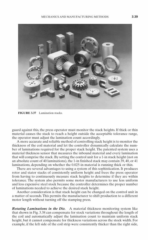
Laminations of all types (see Fig. 3.37) may be staked together into stacks of prede-termined heights as they are stamped in progressive dies during the manufacturingprocess. This staking-in-the-die technique represents an opportunity for bothimproved quality and significant cost reduction to manufacturers of products thatrequire rotor, stator, transformer, ballast, magnet assembly, backpole counterbal-ance, and other types of laminations that subsequently are laminated into stacks.
In addition, symmetrical laminations, such as for rotors for electric motors, maybe rotated in the die prior to staking in order to compensate for material thicknessvariations or to produce a skew angle, as found in many motor designs.
Producing finished stacks of rotor and stator laminations in the die has manyadvantages to the manufacturers of electric motors, particularly the elimination ofdownstream manual or mechanical assembly operations such as riveting or welding.Staking in the die also can produce stacks of more uniform height.
A die capable of staking laminations together requires a specially designed diecavity and special staking punches. The staking punches create protrusions thatcause the individual laminations to stick together as they become a stack in the diecavity.Whether as many as four or more staking punches should be used depends onthe size and design of the rotor or stator part.
Absolute Count Stacking. The easiest way to control stack height is to program amicroprocessor controller for a predetermined number of laminations in each stack.For example, a 1-in rotor using 0.025-in-thick material would require 40 laminations.By programming the die’s staking punches, a 1-in stack of rotors may be producedwith every 40 strokes of the press. The staking process produces tight stacks whichthen are allowed to drop from the die cavity onto a low-profile conveyor.
The integrity of the 1-in stack height is completely dependent on the thicknessconsistency of the 0.025-in coil stock. If the material begins to run thick during thestamping process, 40 laminations could produce an unacceptably long rotor stack.To
FIGURE 3.36 Stack-in-die laminations.
* Subsection contributed by Harry J. Walters and Phil Dolan, Oberg Industries, Inc.
3.38 CHAPTER THREE
guard against this, the press operator must monitor the stack heights. If thick or thinmaterial causes the stack to reach a height outside the acceptable tolerance range,the operator must adjust the lamination count accordingly.
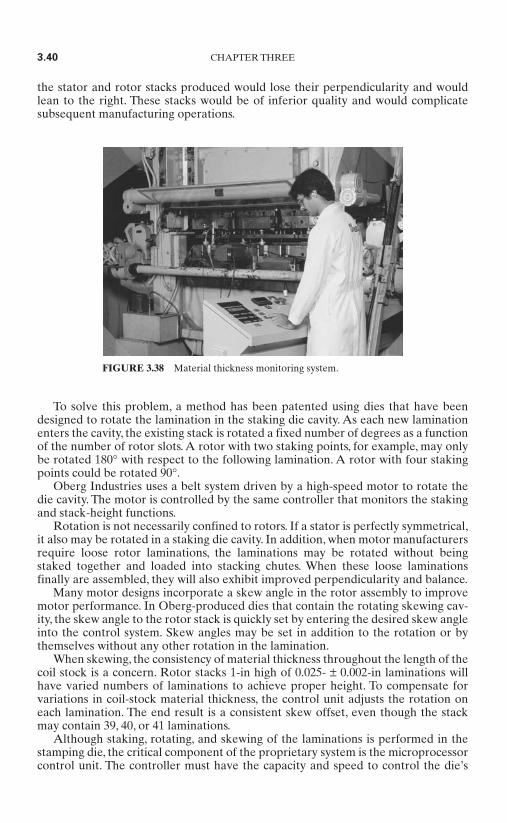
A more accurate and reliable method of controlling stack height is to monitor thethickness of the coil material and let the controller dynamically calculate the num-ber of laminations required for the proper stack height. The patented system uses amaterial thickness sensor that measures the inbound material and every laminationthat will comprise the stack. By setting the control unit for a 1-in stack height (not onan absolute count of 40 laminations), the 1-in finished stack may contain 39, 40, or 41laminations, depending on whether the 0.025-in material is running thick or thin.
There are several advantages to using a system of this sophistication. It producesrotor and stator stacks of consistently uniform height and frees the press operatorfrom having to continuously measure stack heights to determine if they are withintolerance. The system also permits some motor manufacturers to use less uniformand less expensive steel stock because the controller determines the proper numberof laminations needed to achieve the desired stack height.
Another consideration is that stack height can be changed on the control unit ina matter of seconds. This permits the manufacturer to shift production to a differentmotor length without turning off the stamping press.
Rotating Laminations in the Die. A material thickness monitoring system likethat shown in Fig. 3.38 can compensate for stock variations throughout the length ofthe coil and automatically adjust the lamination count to maintain uniform stackheight, but it cannot compensate for thickness variations across the stock width. Forexample, if the left side of the coil strip were consistently thicker than the right side,
MECHANICS AND MANUFACTURING METHODS 3.39
FIGURE 3.37 Lamination stacks.
the stator and rotor stacks produced would lose their perpendicularity and wouldlean to the right. These stacks would be of inferior quality and would complicatesubsequent manufacturing operations.
To solve this problem, a method has been patented using dies that have beendesigned to rotate the lamination in the staking die cavity. As each new laminationenters the cavity, the existing stack is rotated a fixed number of degrees as a functionof the number of rotor slots. A rotor with two staking points, for example, may onlybe rotated 180° with respect to the following lamination. A rotor with four stakingpoints could be rotated 90°.
Oberg Industries uses a belt system driven by a high-speed motor to rotate thedie cavity. The motor is controlled by the same controller that monitors the stakingand stack-height functions.
Rotation is not necessarily confined to rotors. If a stator is perfectly symmetrical,it also may be rotated in a staking die cavity. In addition, when motor manufacturersrequire loose rotor laminations, the laminations may be rotated without beingstaked together and loaded into stacking chutes. When these loose laminationsfinally are assembled, they will also exhibit improved perpendicularity and balance.
Many motor designs incorporate a skew angle in the rotor assembly to improvemotor performance. In Oberg-produced dies that contain the rotating skewing cav-ity, the skew angle to the rotor stack is quickly set by entering the desired skew angleinto the control system. Skew angles may be set in addition to the rotation or bythemselves without any other rotation in the lamination.
When skewing, the consistency of material thickness throughout the length of thecoil stock is a concern. Rotor stacks 1-in high of 0.025- ± 0.002-in laminations willhave varied numbers of laminations to achieve proper height. To compensate forvariations in coil-stock material thickness, the control unit adjusts the rotation oneach lamination. The end result is a consistent skew offset, even though the stackmay contain 39, 40, or 41 laminations.
Although staking, rotating, and skewing of the laminations is performed in thestamping die, the critical component of the proprietary system is the microprocessorcontrol unit. The controller must have the capacity and speed to control the die’s
3.40 CHAPTER THREE
FIGURE 3.38 Material thickness monitoring system.

staking punches, the high-speed motor that drives the rotation cavity, and the mate-rial monitoring sensor, as well as permit the stamping press to operate at top speed.Some lamination die controllers may have to eliminate features to avoid signifi-cantly slowing the press speed.
System Benefits. Whether the motor manufacturer stamps its own laminations orbuys them from a lamination stamper, staking, rotating, and skewing in the die offersseveral benefits. One of the benefits of the technology is that it requires less materialhandling. Staked lamination stacks eliminate much of the handling and moving asso-ciated with loose laminations. Some motor manufacturers are able to send stacks onconveyors to the next process area, directly from the press.
For many types of motors, staked rotor and stator stacks may eliminate weldingand riveting operations.The labor and costs associated with these operations is elim-inated, and there also is no need to replace welding and riveting equipment when itwears out.
One motor manufacturer, faced with the replacement of an obsolete welding line,invested instead in a staking die and controller. The company calculated a two-month payback on the investment and, in addition, was able to access much-neededfloor space when the welding line was removed. The manufacturer intends to elimi-nate all welding in the plant within two years.
The rotor and stator stacks produced with the staking-and-rotation technique areconsistently of higher quality than those produced from loose laminations. Somemanufacturers using staking dies have realized a reduction in the costs associatedwith balancing and other motor-finishing operations. Motor performance also hasbeen improved.
For manufacturers that stamp their own laminations, the benefits related to pro-duction flexibility may be substantial. Stack height and skew angle are changed eas-ily, and combinations of height, skew angle, and rotation can be varied and adjustedby the operator.
Die and Controller Requirements. Rotation, skewing, and staking of laminations,the process used to produce the sample stacks shown in Fig. 3.39, presents severalchallenges to the die or controller supplier. The basic accuracy requirements of therotational motion are recognized when one considers that a 10° skew angle in a 40-lamination stack results from the rotation of each individual lamination by 0.25°.Variations in material thickness can adjust that by 0.00005° or less. Also, extremelyhigh accuracy is required in the stamping die to permit rotation of laminations whilemaintaining concentricity. The location of the stakes must be perfectly symmetrical
MECHANICS AND MANUFACTURING METHODS 3.41
FIGURE 3.39 Sample lamination stacks.

for them to attach properly to the preceding rotated lamination. Rotation of square,rectangular, or other nonround shapes requires extreme accuracy of the rotationalmotion, since the punch is now penetrating a moving die section. It also requiresmechanical devices that will prevent damage if the rotating chamber does not alignwith the punch.
The design and construction of the controller must take into account the fact thatthe system will be operated in a pressroom environment, and must minimize bothadditions to the operator’s workload and intrusion into the already crowded workspace. A simplified operator interface and a rugged, vibration-resistant package arebasic to the operational success of a staking and stamping die.
Technology Limitations. There are areas within this staking and rotating technol-ogy where motor manufacturers face some limitations and cautions. First and mostimportant, it should be noted that the staking process requires a sufficient open areaon the face of the rotor and stator laminations to allow a stake protrusion to bemade without distorting a critical dimension of the lamination. When designing alamination with staking in mind, the advice of a die designer is essential.
Multipart dies are common in the motor industry, and staking dies have beenbuilt that produce as many as five rotors at a time.
Although staking and rotating dies for smaller-sized rotors may not requirereduced press speeds, the rotation of the die cavity for larger-diameter rotors couldforce a press to run more slowly. Also, for annealed laminations, the electrical prop-erties of staked stacks must be compared critically to those of stacks made fromloose laminations. Motor manufacturers that stake stacks in the die generally havefound few differences of consequence, but it is a factor to be considered whendesigning a motor.
Although the tightness and integrity of staked stacks usually are not problems,some handling precautions are advisable to prevent stack delamination. One manu-facturer permits its stacks to drop almost 4 ft from the press into a collecting bin, butthis kind of handling may not be suitable for some types of lamination designs.
The technology of staking, stacking, rotating, and skewing in the stamping die,along with other emerging technologies designed to reduce costs and improve qual-ity, should position the small-motor industry to compete successfully in the globaleconomy.
3.10.6 Electric Motor Stator Lacing*
Stator lacing is the process of tightly securing the field coil ends of an electric motorstator with a stitched cord (see Fig. 3.40). Lacing is typically used on long-life-expectancy or high-efficiency motors where the cost of failure is high. Generally,low-cost “throwaway” motors are not laced. There are several reasons for lacingmotor stators:
The lacing holds the thermal protector, coil ends, and leads in the proper position. Lacing extends a motor’s life by preventing the wires in the coils from vibrating
and causing fatigue failure during operation.
3.42 CHAPTER THREE
* Subsection contributed by Warren C. Brown, Link Engineering Company.
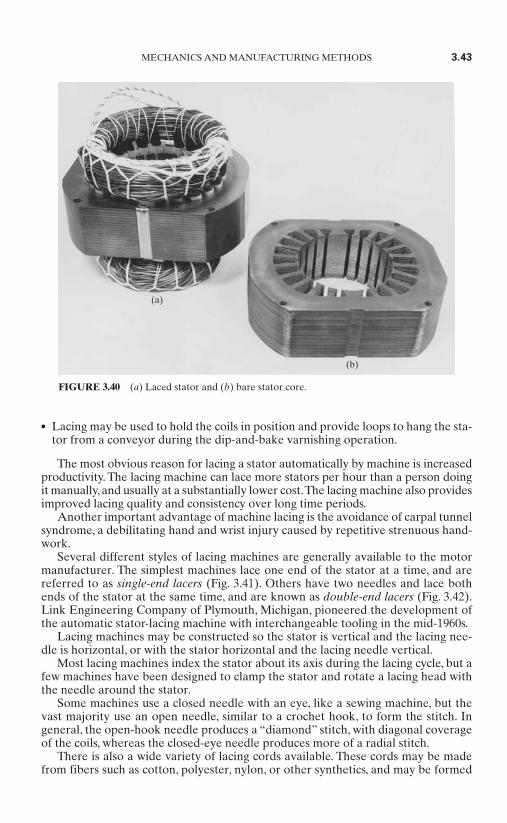
Lacing may be used to hold the coils in position and provide loops to hang the sta-tor from a conveyor during the dip-and-bake varnishing operation.
The most obvious reason for lacing a stator automatically by machine is increasedproductivity. The lacing machine can lace more stators per hour than a person doingit manually, and usually at a substantially lower cost.The lacing machine also providesimproved lacing quality and consistency over long time periods.
Another important advantage of machine lacing is the avoidance of carpal tunnelsyndrome, a debilitating hand and wrist injury caused by repetitive strenuous hand-work.
Several different styles of lacing machines are generally available to the motormanufacturer. The simplest machines lace one end of the stator at a time, and arereferred to as single-end lacers (Fig. 3.41). Others have two needles and lace bothends of the stator at the same time, and are known as double-end lacers (Fig. 3.42).Link Engineering Company of Plymouth, Michigan, pioneered the development ofthe automatic stator-lacing machine with interchangeable tooling in the mid-1960s.
Lacing machines may be constructed so the stator is vertical and the lacing nee-dle is horizontal, or with the stator horizontal and the lacing needle vertical.
Most lacing machines index the stator about its axis during the lacing cycle, but afew machines have been designed to clamp the stator and rotate a lacing head withthe needle around the stator.
Some machines use a closed needle with an eye, like a sewing machine, but thevast majority use an open needle, similar to a crochet hook, to form the stitch. Ingeneral, the open-hook needle produces a “diamond” stitch, with diagonal coverageof the coils, whereas the closed-eye needle produces more of a radial stitch.
There is also a wide variety of lacing cords available. These cords may be madefrom fibers such as cotton, polyester, nylon, or other synthetics, and may be formed
MECHANICS AND MANUFACTURING METHODS 3.43
FIGURE 3.40 (a) Laced stator and (b) bare stator core.
(a)
(b)
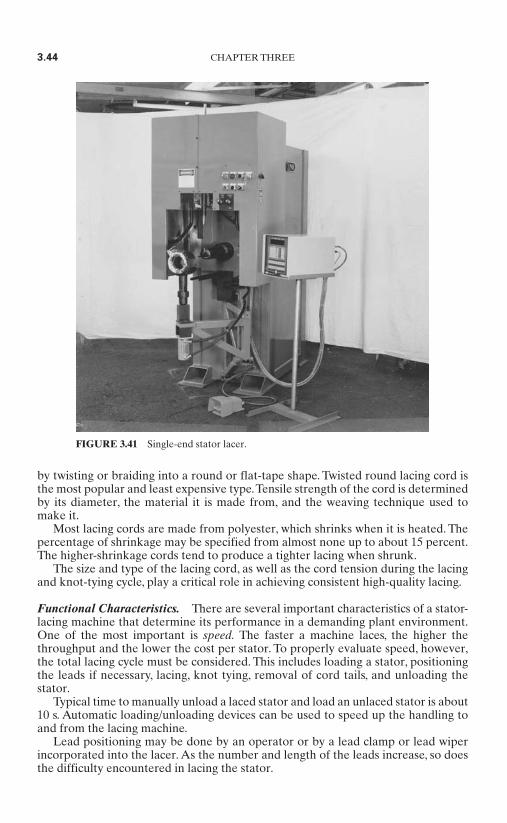
by twisting or braiding into a round or flat-tape shape. Twisted round lacing cord isthe most popular and least expensive type.Tensile strength of the cord is determinedby its diameter, the material it is made from, and the weaving technique used tomake it.
Most lacing cords are made from polyester, which shrinks when it is heated. Thepercentage of shrinkage may be specified from almost none up to about 15 percent.The higher-shrinkage cords tend to produce a tighter lacing when shrunk.
The size and type of the lacing cord, as well as the cord tension during the lacingand knot-tying cycle, play a critical role in achieving consistent high-quality lacing.
Functional Characteristics. There are several important characteristics of a stator-lacing machine that determine its performance in a demanding plant environment.One of the most important is speed. The faster a machine laces, the higher thethroughput and the lower the cost per stator. To properly evaluate speed, however,the total lacing cycle must be considered. This includes loading a stator, positioningthe leads if necessary, lacing, knot tying, removal of cord tails, and unloading the stator.
Typical time to manually unload a laced stator and load an unlaced stator is about10 s. Automatic loading/unloading devices can be used to speed up the handling toand from the lacing machine.
Lead positioning may be done by an operator or by a lead clamp or lead wiperincorporated into the lacer. As the number and length of the leads increase, so doesthe difficulty encountered in lacing the stator.
3.44 CHAPTER THREE
FIGURE 3.41 Single-end stator lacer.
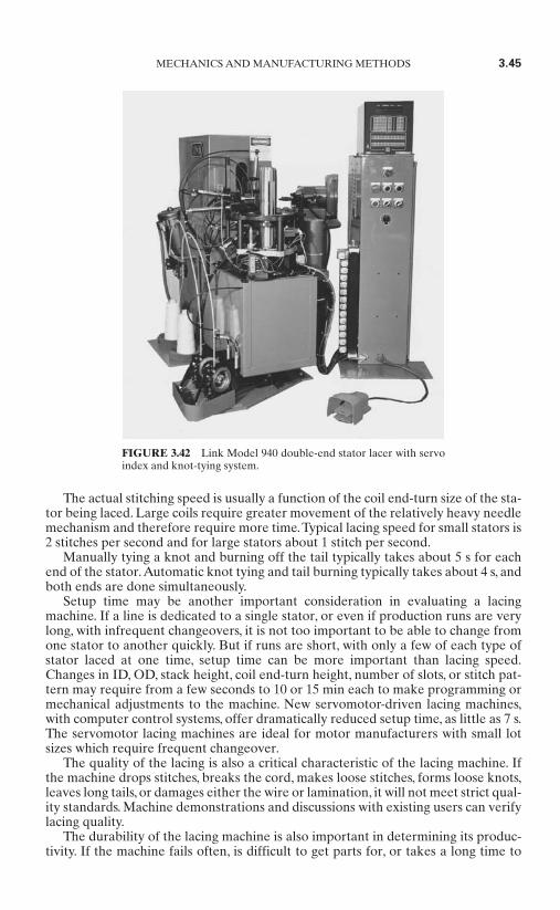
The actual stitching speed is usually a function of the coil end-turn size of the sta-tor being laced. Large coils require greater movement of the relatively heavy needlemechanism and therefore require more time.Typical lacing speed for small stators is2 stitches per second and for large stators about 1 stitch per second.
Manually tying a knot and burning off the tail typically takes about 5 s for eachend of the stator.Automatic knot tying and tail burning typically takes about 4 s, andboth ends are done simultaneously.
Setup time may be another important consideration in evaluating a lacingmachine. If a line is dedicated to a single stator, or even if production runs are verylong, with infrequent changeovers, it is not too important to be able to change fromone stator to another quickly. But if runs are short, with only a few of each type ofstator laced at one time, setup time can be more important than lacing speed.Changes in ID, OD, stack height, coil end-turn height, number of slots, or stitch pat-tern may require from a few seconds to 10 or 15 min each to make programming ormechanical adjustments to the machine. New servomotor-driven lacing machines,with computer control systems, offer dramatically reduced setup time, as little as 7 s.The servomotor lacing machines are ideal for motor manufacturers with small lotsizes which require frequent changeover.
The quality of the lacing is also a critical characteristic of the lacing machine. Ifthe machine drops stitches, breaks the cord, makes loose stitches, forms loose knots,leaves long tails, or damages either the wire or lamination, it will not meet strict qual-ity standards. Machine demonstrations and discussions with existing users can verifylacing quality.
The durability of the lacing machine is also important in determining its produc-tivity. If the machine fails often, is difficult to get parts for, or takes a long time to
MECHANICS AND MANUFACTURING METHODS 3.45
FIGURE 3.42 Link Model 940 double-end stator lacer with servoindex and knot-tying system.

repair, it will not meet overall throughput goals. A proven machine design from areputable company is the best assurance that the machine will deliver uninterruptedperformance on the plant floor.
Typical Lacing-Machine Features and Options. Although a basic stator-lacingmachine can be a big improvement over hand lacing, many features and optionsmake the process faster or more flexible.
A time-saving option is automatic knot tying. This device forms a secure, tightknot, then burns off the tail and vacuums it into a waste container. A device is alsoavailable to fully automate the cord cutting and clamping at the end of the knot-tying cycle.
Automatic stator lifting and lowering raises and lowers the stator so the operatorcan easily grasp it. This feature is particularly useful for stators that have short stackheights or are particularly heavy.
Automatic stator loading and unloading can take the form of a manually assistedarm and gripper or a fully automatic robotic handling device. These loading/unload-ing systems can be integrated into a fully automated line to virtually eliminate therequirement for an operator.
Broken-cord and end-of-cord sensors enable detection of the end of a spool ofcord or a break in a cord.This is especially useful in fully automatic lines that do nothave an operator to observe such cord faults.
Computer-based touch-screen control systems offer simple programming, graphicdisplays, internal documentation, diagnostics, machine statistics, and large data-storage capacity.
Nonradial slot lacing allows manufacturers to lace stators with odd slots that arenot in line with the center of the stator core.
A hanger loop option forms two long loops in the lacing cord at opposite sides ofthe stator, so the stator can be hung from a conveyor for processing through a var-nish bath.
Roller casters may be placed under the legs of the lacer and the electrical box toenable easy movement of the machine from one location in the plant to another.
Summary. The automatic stator-lacing machine has a proven track record of beinga productive, reliable, cost-effective tool for motor manufacturers seeking to pro-duce high-quality motors at a competitive price. Many evolutionary changes haveled to a wide variety of models and options incorporating significant improvementsin flexibility, reliability, and speed.
3.11 BEARING SYSTEMS FOR SMALL ELECTRICMOTORS*
Electric motors are devices that convert electrical energy into magnetic energy andfinally into mechanical energy. The mechanical energy is generally transmitted fromthe rotor through a shaft that must be free to rotate in some type of bearing system(see Fig. 3.43). The choice of the bearing system is key to the motor’s performanceand life.
3.46 CHAPTER THREE
* Section contributed by William H. Yeadon and Alan W. Yeadon, Yeadon Engineering Services, PC,except as noted. Basic technical information courtesy of Nye Lubricants and NMB Corporation.

The system generally consists of a shaft, a bearing, and a lubricant arranged in afashion that maintains a film of lubricant between the shaft and the bearing surface.The components and system are typically chosen to meet the requirement of thespecific application.
This section first discusses the components, then systems, and finally the applica-tion.
3.11.1 Bearings
Bearing systems are used to support the rotor and shaft assembly so that it remainsin a certain constant position relative to the stator and so as to reduce the frictionbetween the shaft and the end frames. The most common bearings used in motorsare ball bearings and sleeve bearings. Ball bearings are typically constructed asshown in Fig. 3.44. They consist of an inner race and outer race, balls, and a ball car-rier.The races and balls are typically highly polished hardened steel.The ball carriermay be steel or plastic.
The inner race supports the shaft and rotates with it. The outer race is held sta-tionary in the end frame. The balls provide a low-friction method of allowing theinner race to roll with respect to the outer race as the shaft turns. The carrier main-tains proper spacing of the balls to evenly distribute the load.
Ball bearings are lubricated by injecting grease around the balls between theraces.The grease may be contained by means of a shield or seal that fits between theraces. Sealed bearings have a higher coefficient of friction, require more torque fromthe motor, and are more costly than shielded bearings. Therefore, they are used inapplications such as pumps where it is necessary to keep moisture or corrosiveagents out of the bearings.
Ball bearings need to be preloaded to keep the balls from moving freely in theaxial direction. The amount of preload is listed in the bearing manufacturer’s datafor each type of bearing. Preloading is generally accomplished by means of a coilspring or wavy washer.
MECHANICS AND MANUFACTURING METHODS 3.47
FIGURE 3.43 Electric motor components.
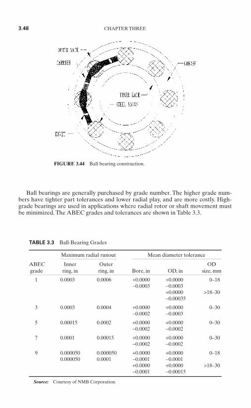
Ball bearings are generally purchased by grade number. The higher grade num-bers have tighter part tolerances and lower radial play, and are more costly. High-grade bearings are used in applications where radial rotor or shaft movement mustbe minimized. The ABEC grades and tolerances are shown in Table 3.3.
3.48 CHAPTER THREE
FIGURE 3.44 Ball bearing construction.
TABLE 3.3 Ball-Bearing Grades
Maximum radial runout Mean diameter tolerance
ABEC Inner Outer ODgrade ring, in ring, in Bore, in OD, in size, mm
1 0.0003 0.0006 +0.0000 +0.0000 0–18−0.0003 −0.0003
+0.0000 >18–30−0.00035
3 0.0003 0.0004 +0.0000 +0.0000 0–30−0.0002 −0.0003
5 0.00015 0.0002 +0.0000 +0.0000 0–30−0.0002 −0.0002
7 0.0001 0.00015 +0.0000 +0.0000 0–30−0.0002 −0.0002
9 0.000050 0.000050 +0.0000 +0.0000 0–180.000050 0.0001 −0.0001 −0.0001
+0.0000 +0.0000 >18–30−0.0001 −0.00015
Source: Courtesy of NMB Corporation.
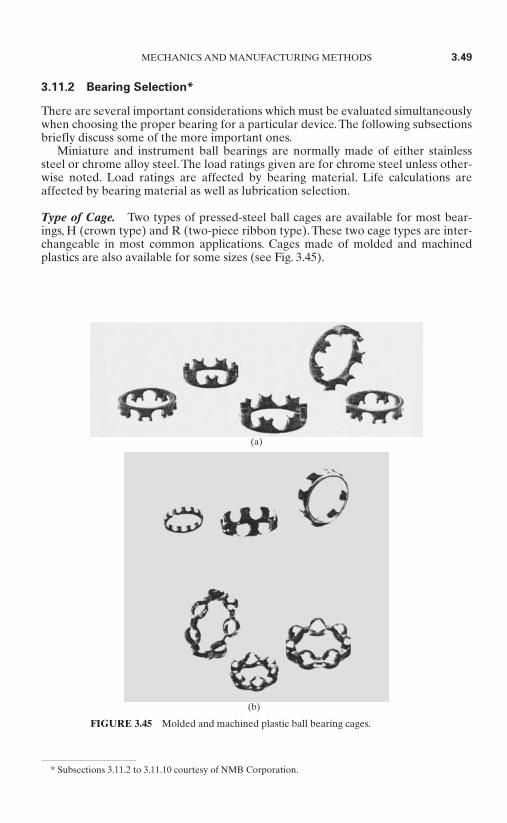
3.11.2 Bearing Selection*
There are several important considerations which must be evaluated simultaneouslywhen choosing the proper bearing for a particular device. The following subsectionsbriefly discuss some of the more important ones.
Miniature and instrument ball bearings are normally made of either stainlesssteel or chrome alloy steel. The load ratings given are for chrome steel unless other-wise noted. Load ratings are affected by bearing material. Life calculations areaffected by bearing material as well as lubrication selection.
Type of Cage. Two types of pressed-steel ball cages are available for most bear-ings, H (crown type) and R (two-piece ribbon type). These two cage types are inter-changeable in most common applications. Cages made of molded and machinedplastics are also available for some sizes (see Fig. 3.45).
MECHANICS AND MANUFACTURING METHODS 3.49
* Subsections 3.11.2 to 3.11.10 courtesy of NMB Corporation.
FIGURE 3.45 Molded and machined plastic ball bearing cages.
(b)
(a)

Shields and Seals. Shields are available for most sizes. These closures help toreduce the entrance of particulate contaminants into the bearing and reduce theamount of lubricant leakage. Radial clearance between the shield bore and the innerring OD is approximately 0.002 to 0.005 in. The effect of shields on bearing torqueor noise is insignificant.
Contacting seals made of synthetic rubber (type DD), as shown in Fig. 3.46, areavailable for most sizes.These seals provide the best protection from the entrance of
contaminants or exit of lubricant, butthey significantly increase operatingtorque. DD seals will withstand a slightamount of positive pressure differential.
Noncontacting seals made of syn-thetic rubber (type SS) or reinforcedpolytetrafluoroethylene [PTFE (Teflon;type LL)], as shown in Fig. 3.47, are alsoavailable for most chassis sizes.This typeof seal offers better sealing than a metalshield, while keeping operating torqueat the lowest possible levels. LL sealswill contact the inner ring in some cases,but the nature of the seal material servesto keep torque at a minimum.
Radial Play. Radial play is the freeinternal radial looseness between theballs and races. Radial play within a ball
bearing is necessary to accommodate thermal expansion and the effects of interfer-ence fits and to control axial play.Table 3.4 suggests radial play ranges for some typ-ical uses.
Starting and Running Torque. The operating torque of a bearing can be describedas starting and running torque. Starting torque is the torque required to begin rota-tion from a bearing at rest. Running torque is the torque required to rotate one ringat a known speed while keeping the other ring stationary. The main contributors tobearing torque are seal and lubrication type.
3.50 CHAPTER THREE
FIGURE 3.46 Contacting seals (type DD, syn-thetic rubber).
FIGURE 3.47 Noncontacting seals (type LL,reinforced Teflon).
TABLE 3.4 Radial Play Ranges
Typical application Suggested radial play, in
Small high-speed precision 0.0005–0.0008electric motors
Tape guides and belt guides, 0.0002–0.0005low speed
Tape guides and belt guides, 0.0005–0.0008high speed
Precision gear trains, 0.0002–0.0005low-speed electric motors,synchros, and servos
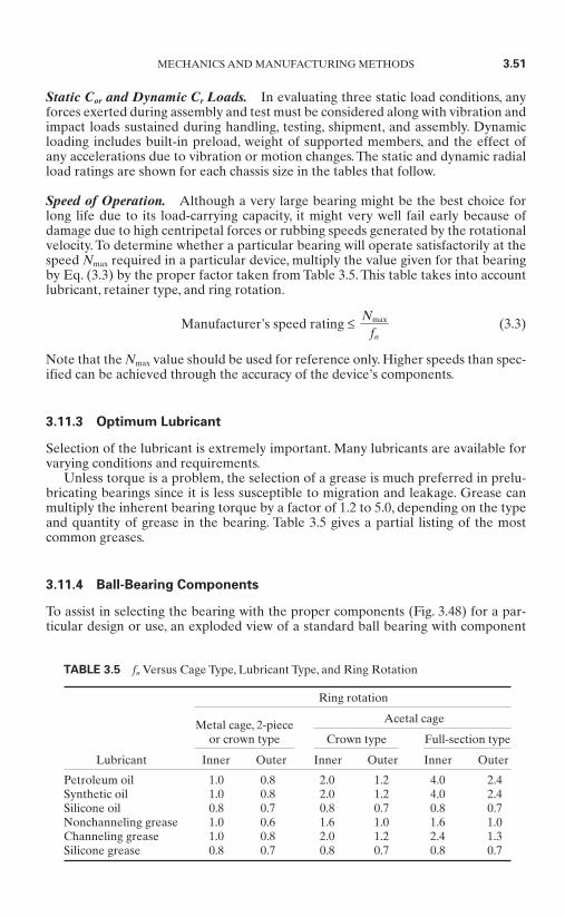
Static Cor and Dynamic Cr Loads. In evaluating three static load conditions, anyforces exerted during assembly and test must be considered along with vibration andimpact loads sustained during handling, testing, shipment, and assembly. Dynamicloading includes built-in preload, weight of supported members, and the effect ofany accelerations due to vibration or motion changes. The static and dynamic radialload ratings are shown for each chassis size in the tables that follow.
Speed of Operation. Although a very large bearing might be the best choice forlong life due to its load-carrying capacity, it might very well fail early because ofdamage due to high centripetal forces or rubbing speeds generated by the rotationalvelocity. To determine whether a particular bearing will operate satisfactorily at thespeed Nmax required in a particular device, multiply the value given for that bearingby Eq. (3.3) by the proper factor taken from Table 3.5. This table takes into accountlubricant, retainer type, and ring rotation.
Manufacturer’s speed rating ≤ (3.3)
Note that the Nmax value should be used for reference only. Higher speeds than spec-ified can be achieved through the accuracy of the device’s components.
3.11.3 Optimum Lubricant
Selection of the lubricant is extremely important. Many lubricants are available forvarying conditions and requirements.
Unless torque is a problem, the selection of a grease is much preferred in prelu-bricating bearings since it is less susceptible to migration and leakage. Grease canmultiply the inherent bearing torque by a factor of 1.2 to 5.0, depending on the typeand quantity of grease in the bearing. Table 3.5 gives a partial listing of the mostcommon greases.
3.11.4 Ball-Bearing Components
To assist in selecting the bearing with the proper components (Fig. 3.48) for a par-ticular design or use, an exploded view of a standard ball bearing with component
Nmaxfn
MECHANICS AND MANUFACTURING METHODS 3.51
TABLE 3.5 fn Versus Cage Type, Lubricant Type, and Ring Rotation
Ring rotation
Acetal cage
Crown type Full-section type
Lubricant Inner Outer Inner Outer Inner Outer
Petroleum oil 1.0 0.8 2.0 1.2 4.0 2.4Synthetic oil 1.0 0.8 2.0 1.2 4.0 2.4Silicone oil 0.8 0.7 0.8 0.7 0.8 0.7Nonchanneling grease 1.0 0.6 1.6 1.0 1.6 1.0Channeling grease 1.0 0.8 2.0 1.2 2.4 1.3Silicone grease 0.8 0.7 0.8 0.7 0.8 0.7
Metal cage, 2-pieceor crown type
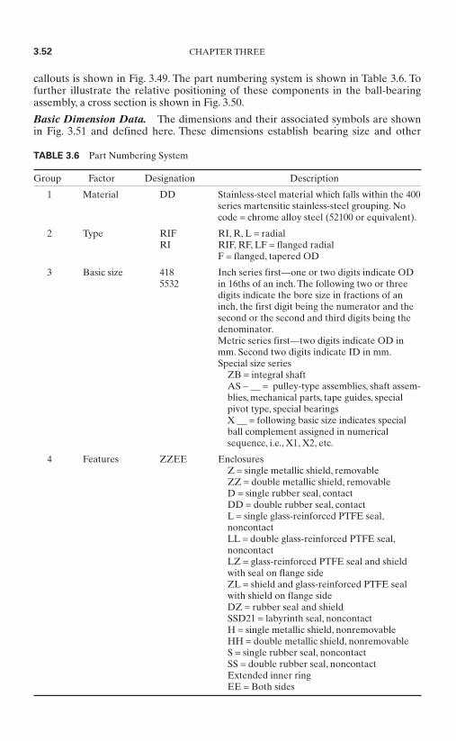
callouts is shown in Fig. 3.49. The part numbering system is shown in Table 3.6. Tofurther illustrate the relative positioning of these components in the ball-bearingassembly, a cross section is shown in Fig. 3.50.
Basic Dimension Data. The dimensions and their associated symbols are shownin Fig. 3.51 and defined here. These dimensions establish bearing size and other
3.52 CHAPTER THREE
TABLE 3.6 Part Numbering System
Group Factor Designation Description
1 Material DD Stainless-steel material which falls within the 400series martensitic stainless-steel grouping. Nocode = chrome alloy steel (52100 or equivalent).
2 Type RIF RI, R, L = radialRI RIF, RF, LF = flanged radial
F = flanged, tapered OD
3 Basic size 418 Inch series first—one or two digits indicate OD 5532 in 16ths of an inch. The following two or three
digits indicate the bore size in fractions of aninch, the first digit being the numerator and thesecond or the second and third digits being thedenominator.Metric series first—two digits indicate OD inmm. Second two digits indicate ID in mm.Special size series
ZB = integral shaftAS − = pulley-type assemblies, shaft assem-blies, mechanical parts, tape guides, specialpivot type, special bearingsX = following basic size indicates specialball complement assigned in numericalsequence, i.e., X1, X2, etc.
4 Features ZZEE EnclosuresZ = single metallic shield, removableZZ = double metallic shield, removableD = single rubber seal, contactDD = double rubber seal, contactL = single glass-reinforced PTFE seal,noncontactLL = double glass-reinforced PTFE seal,noncontactLZ = glass-reinforced PTFE seal and shieldwith seal on flange sideZL = shield and glass-reinforced PTFE sealwith shield on flange sideDZ = rubber seal and shield SSD21 = labyrinth seal, noncontactH = single metallic shield, nonremovableHH = double metallic shield, nonremovableS = single rubber seal, noncontactSS = double rubber seal, noncontactExtended inner ringEE = Both sides
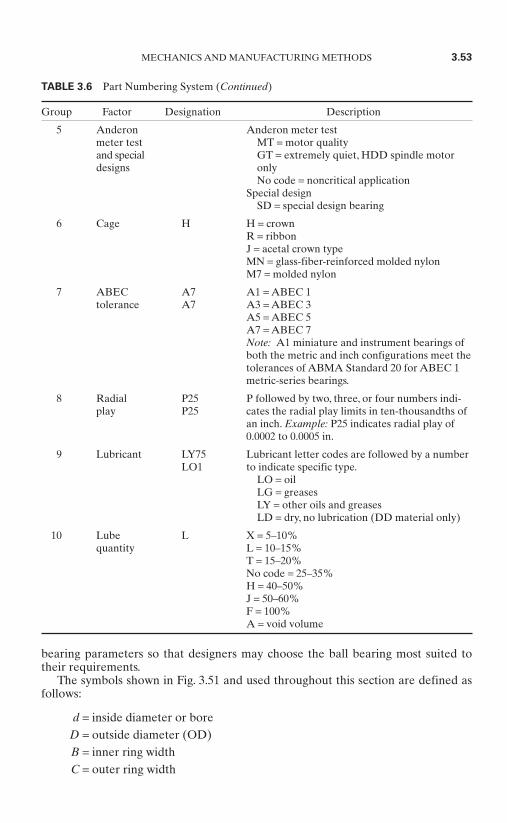
bearing parameters so that designers may choose the ball bearing most suited totheir requirements.
The symbols shown in Fig. 3.51 and used throughout this section are defined asfollows:
d = inside diameter or boreD = outside diameter (OD)B = inner ring widthC = outer ring width
MECHANICS AND MANUFACTURING METHODS 3.53
TABLE 3.6 Part Numbering System (Continued)
Group Factor Designation Description
5 Anderon Anderon meter testmeter test MT = motor qualityand special GT = extremely quiet, HDD spindle motordesigns only
No code = noncritical applicationSpecial design
SD = special design bearing
6 Cage H H = crownR = ribbonJ = acetal crown typeMN = glass-fiber-reinforced molded nylonM7 = molded nylon
7 ABEC A7 A1 = ABEC 1tolerance A7 A3 = ABEC 3
A5 = ABEC 5A7 = ABEC 7Note: A1 miniature and instrument bearings ofboth the metric and inch configurations meet thetolerances of ABMA Standard 20 for ABEC 1metric-series bearings.
8 Radial P25 P followed by two, three, or four numbers indi-play P25 cates the radial play limits in ten-thousandths of
an inch. Example: P25 indicates radial play of0.0002 to 0.0005 in.
9 Lubricant LY75 Lubricant letter codes are followed by a numberLO1 to indicate specific type.
LO = oilLG = greasesLY = other oils and greasesLD = dry, no lubrication (DD material only)
10 Lube L X = 5–10%quantity L = 10–15%
T = 15–20%No code = 25–35%H = 40–50%J = 50–60%F = 100%A = void volume

3.54 CHAPTER THREE
FIGURE 3.48 Ball bearing components.
FIGURE 3.49 Cross section of ball bearing.

Df = flange outside diameterBf = flange width or thicknessLi = inner ring reference diameterLo = outer ring reference diameter
r = maximum shaft of housing fillet radius that bearing corners will clearZ = number of balls
DW = nominal diameter of ballsNmax = maximum speed, rpm
fn = cage and lubricant factor (See Table 3.5.)
3.11.5 Internal Bearing Geometry
When designing ball bearings for optimum performance, internal bearing geometryis a critical factor. For any given bearing load, internal stresses can be either high orlow, depending on the geometric relationship between the balls and raceways insidethe ball-bearing structure.
When a ball bearing is running under a load, force is transmitted from one bear-ing ring to the other through the ball set. Since the contact area between each balland the rings is relatively small, even moderate loads can produce stresses of tens oreven hundreds of thousands of pounds per square inch. Because internal stress lev-els have such an important effect on bearing life and performance, internal geome-try must be carefully chosen for each application so bearing loads can be distributedproperly.
Raceway, Track Diameter, and Track Radius. The raceway in a ball bearing is thecircular groove formed in the outside surface of the inner ring and in the inside sur-face of the outer ring.When the rings are aligned, these grooves form a circular trackthat contains the ball set.
MECHANICS AND MANUFACTURING METHODS 3.55
FIGURE 3.50 Bearing components.

The track diameter and track radiusare two dimensions that define the con-figuration of each raceway. Track diame-ter is the measurement of the diameterof the imaginary circle running aroundthe deepest portion of the raceway,whether it be an inner or outer ring.Thismeasurement is made along a line per-pendicular to, and intersecting, the axisof rotation. Track radius describes thecross section of the arc formed by theraceway groove. It is measured whenviewed in a direction perpendicular tothe axis of the ring. In the context ofball-bearing terminology, track radiushas no mathematical relationship totrack diameter. The distinction betweenthe two is shown in Fig. 3.52.
Radial and Axial Play. Most ballbearings are assembled in such a waythat a slight amount of looseness existsbetween balls and raceways. This loose-ness is referred to as radial play andaxial play. Specifically, radial play is themaximum distance that one bearing ringcan be displaced with respect to theother, in a direction perpendicular to thebearing axis, when the bearing is in anunmounted state. Axial play, or end play,is the maximum relative displacementbetween the two rings of an unmountedball bearing in the direction parallel tothe bearing axis. Figure 3.53 illustratesthese concepts.
Since radial play and axial play areboth consequences of the same degree
of looseness between the components in a ball bearing, they bear a mutual depen-dence. While this is true, both values are usually quite different in magnitude.
In most ball-bearing applications, radial play is functionally more critical thanaxial play. If axial play is determined to be an essential requirement, control can beobtained through manipulation of the radial-play specification.
3.56 CHAPTER THREE
FIGURE 3.51 Bearing dimensions and sym-bols.
FIGURE 3.52 Distinction between track radius andtrack diameter.

Some general statements about radial play follow.
The initial contact angle of the bearing isdirectly related to radial play—the higherthe radial play, the higher the contact angle.Table 3.7 shows nominal contact angles, andTable 3.8 shows typical radial-play ranges.The contact angles in Table 3.7 are given forthe mean radial play of the ranges shown—i.e., for P25 (0.0002 to 0.0005 in), the contactangle is given for 0.00035 in. Contact angle isaffected by raceway curvature.
For support of pure radial loads, a low levelof radial play is desirable.Where thrust load-ing is predominant, higher radial-play levelsare recommended.
Radial play is affected by any interference fitbetween the shaft and bearing ID or be-tween the housing and bearing OD.
Raceway Curvature. Raceway curvature is an expression that defines the relation-ship between the arc of the raceway’s track radius and the arc formed by the slightlysmaller ball that runs in the raceway. It is simply the track radius of the bearing race-way expressed as a percentage of the ball diameter. This number is a convenientindex of fit between the raceway and ball. Figure 3.54 illustrates this relationship.
Track curvature values typically range from approximately 52 to 58 percent. Thelower-percentage, tight-fitting curvatures are useful in applications where heavyloads are encountered. The higher-percentage, loose curvatures are more suitable
MECHANICS AND MANUFACTURING METHODS 3.57
FIGURE 3.53 Distinction between radial and axial play.
TABLE 3.7 Ball-Bearing ContactAngles
Ball sizeDW P25 P58
0.025 in 18° 241⁄2°1⁄32 in (0.8 mm) 161⁄2° 22°1 mm 141⁄2° 20°3⁄64 in 14° 18°1⁄16 in 12° 16°3⁄32 in 91⁄2° 13°1⁄8 in 121⁄2° 17°9⁄64 in 12° 16°5⁄32 in 11° 15°3⁄16 in 10° 14°
Radial-play code
TABLE 3.8 Typical Radial-Play Ranges
Description Radial-play range NMB code
Tight 0.0001–0.0003 in P13Normal 0.0002–0.0005 in P25Loose 0.0005–0.0008 in P58
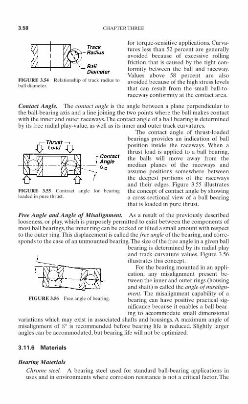
for torque-sensitive applications. Curva-tures less than 52 percent are generallyavoided because of excessive rollingfriction that is caused by the tight con-formity between the ball and raceway.Values above 58 percent are alsoavoided because of the high stress levelsthat can result from the small ball-to-raceway conformity at the contact area.
Contact Angle. The contact angle is the angle between a plane perpendicular tothe ball-bearing axis and a line joining the two points where the ball makes contactwith the inner and outer raceways. The contact angle of a ball bearing is determinedby its free radial play-value, as well as its inner and outer track curvatures.
The contact angle of thrust-loadedbearings provides an indication of ballposition inside the raceways. When athrust load is applied to a ball bearing,the balls will move away from themedian planes of the raceways andassume positions somewhere betweenthe deepest portions of the racewaysand their edges. Figure 3.55 illustratesthe concept of contact angle by showinga cross-sectional view of a ball bearingthat is loaded in pure thrust.
Free Angle and Angle of Misalignment. As a result of the previously describedlooseness, or play, which is purposely permitted to exist between the components ofmost ball bearings, the inner ring can be cocked or tilted a small amount with respectto the outer ring.This displacement is called the free angle of the bearing, and corre-sponds to the case of an unmounted bearing.The size of the free angle in a given ball
bearing is determined by its radial playand track curvature values. Figure 3.56illustrates this concept.
For the bearing mounted in an appli-cation, any misalignment present be-tween the inner and outer rings (housingand shaft) is called the angle of misalign-ment. The misalignment capability of abearing can have positive practical sig-nificance because it enables a ball bear-ing to accommodate small dimensional
variations which may exist in associated shafts and housings. A maximum angle ofmisalignment of 1⁄4° is recommended before bearing life is reduced. Slightly largerangles can be accommodated, but bearing life will not be optimized.
3.11.6 Materials
Bearing MaterialsChrome steel. A bearing steel used for standard ball-bearing applications inuses and in environments where corrosion resistance is not a critical factor. The
3.58 CHAPTER THREE
FIGURE 3.54 Relationship of track radius toball diameter.
FIGURE 3.55 Contract angle for bearingloaded in pure thrust.
FIGURE 3.56 Free angle of bearing.
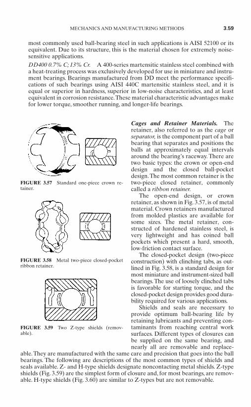
most commonly used ball-bearing steel in such applications is AISI 52100 or itsequivalent. Due to its structure, this is the material chosen for extremely noise-sensitive applications.DD400 0.7% C; 13% Cr. A 400-series martensitic stainless steel combined witha heat-treating process was exclusively developed for use in miniature and instru-ment bearings. Bearings manufactured from DD meet the performance specifi-cations of such bearings using AISI 440C martensitic stainless steel, and it isequal or superior in hardness, superior in low-noise characteristics, and at leastequivalent in corrosion resistance.These material characteristic advantages makefor lower torque, smoother running, and longer-life bearings.
Cages and Retainer Materials. Theretainer, also referred to as the cage orseparator, is the component part of a ballbearing that separates and positions theballs at approximately equal intervalsaround the bearing’s raceway. There aretwo basic types: the crown or open-enddesign and the closed ball-pocketdesign.The most common retainer is thetwo-piece closed retainer, commonlycalled a ribbon retainer.
The open-end design, or crownretainer, as shown in Fig. 3.57, is of metalmaterial. Crown retainers manufacturedfrom molded plastics are available forsome sizes. The metal retainer, con-structed of hardened stainless steel, isvery lightweight and has coined ballpockets which present a hard, smooth,low-friction contact surface.
The closed-pocket design (two-piececonstruction) with clinching tabs, as out-lined in Fig. 3.58, is a standard design formost miniature and instrument-sized ballbearings. The use of loosely clinched tabsis favorable for starting torque, and theclosed-pocket design provides good dura-bility required for various applications.
Shields and seals are necessary toprovide optimum ball-bearing life byretaining lubricants and preventing con-taminants from reaching central worksurfaces. Different types of closures canbe supplied on the same bearing, andnearly all are removable and replace-
able.They are manufactured with the same care and precision that goes into the ballbearings. The following are descriptions of the most common types of shields andseals available. Z- and H-type shields designate noncontacting metal shields. Z-typeshields (Fig. 3.59) are the simplest form of closure and, for most bearings, are remov-able. H-type shields (Fig. 3.60) are similar to Z-types but are not removable.
MECHANICS AND MANUFACTURING METHODS 3.59
FIGURE 3.57 Standard one-piece crown re-tainer.
FIGURE 3.58 Metal two-piece closed-pocketribbon retainer.
FIGURE 3.59 Two Z-type shields (remov-able).
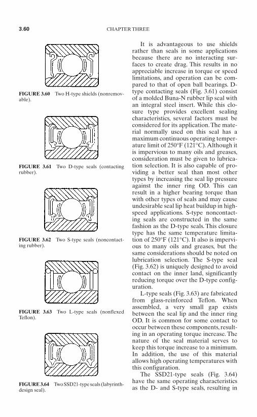
It is advantageous to use shieldsrather than seals in some applicationsbecause there are no interacting sur-faces to create drag. This results in noappreciable increase in torque or speedlimitations, and operation can be com-pared to that of open ball bearings. D-type contacting seals (Fig. 3.61) consistof a molded Buna-N rubber lip seal withan integral steel insert. While this clo-sure type provides excellent sealingcharacteristics, several factors must beconsidered for its application. The mate-rial normally used on this seal has amaximum continuous operating temper-ature limit of 250°F (121°C).Although itis impervious to many oils and greases,consideration must be given to lubrica-tion selection. It is also capable of pro-viding a better seal than most othertypes by increasing the seal lip pressureagainst the inner ring OD. This canresult in a higher bearing torque thanwith other types of seals and may causeundesirable seal lip heat buildup in high-speed applications. S-type noncontact-ing seals are constructed in the samefashion as the D-type seals. This closuretype has the same temperature limita-tion of 250°F (121°C). It also is impervi-ous to many oils and greases, but thesame considerations should be noted onlubrication selection. The S-type seal(Fig. 3.62) is uniquely designed to avoidcontact on the inner land, significantlyreducing torque over the D-type config-uration.
L-type seals (Fig. 3.63) are fabricatedfrom glass-reinforced Teflon. Whenassembled, a very small gap existsbetween the seal lip and the inner ringOD. It is common for some contact tooccur between these components, result-ing in an operating torque increase. Thenature of the seal material serves tokeep this torque increase to a minimum.In addition, the use of this materialallows high operating temperatures withthis configuration.
The SSD21-type seals (Fig. 3.64)have the same operating characteristicsas the D- and S-type seals, resulting in
3.60 CHAPTER THREE
FIGURE 3.60 Two H-type shields (nonremov-able).
FIGURE 3.61 Two D-type seals (contactingrubber).
FIGURE 3.62 Two S-type seals (noncontact-ing rubber).
FIGURE 3.63 Two L-type seals (nonflexedTeflon).
FIGURE 3.64 Two SSD21-type seals (labyrinth-design seal).
the same considerations of temperature limitation and lubricant selection. TheSSD21-type seal is comprised of a noncontacting rubber seal combined with alabyrinth-design inner ring. The labyrinth-design configuration creates an extendedpath to the raceway, minimizing the tendency for contaminants to creep into the ballbearing.
3.11.7 Lubrication
Lubricant Types. Oil is the basic lubricant for ball bearings. Previously, most lubri-cating oil was refined from petroleum. Today, however, synthetic oils such asdiesters, silicone polymers, and fluorinated compounds have found acceptancebecause of improvements in properties. Compared to petroleum-based oils, diestersin general have better low-temperature properties, lower volatility, and better tem-perature/viscosity characteristics. Silicones and fluorinated compounds possess evenlower volatility and wider temperature/viscosity properties.
Virtually all petroleum and diester oils contain additives that limit chemicalchanges, protect the metal from corrosion, and improve physical properties.
Grease is an oil to which a thickener has been added to prevent oil migrationfrom the lubrication site. It is used in situations where frequent replenishment ofthe lubricant is undesirable or impossible. All of the oil types mentioned in thenext subsection can be used as grease bases to which are added metallic soaps, syn-thetic fillers, and thickeners. The operative properties of grease depend almostwholly on the base oil. Other factors being equal, the use of grease rather than oilresults in higher starting and running torque and can limit the bearing to lowerspeeds.
Oils and Base Fluids. Petroleum lubricants have excellent load-carrying abilities,but are usable only at moderate temperature ranges [−25 to 250°F (−32 to 121°C)].Greases that use petroleum oils for bases have a high dN capability. Greases of thistype are recommended for use at moderate temperatures, light to heavy loads, andmoderate to high speeds.
While superrefined petroleum lubricants are usable at higher temperatures thanpetroleum oils [−65 to 350°F (−54 to 177°C)], they still exhibit the same excellentload-carrying capacity. This further refinement eliminates unwanted properties,leaving only the desired chemical chains. Additives are introduced to increase theoxidation resistance, etc.
The diesters are probably the most common synthetic lubricants. They do nothave the film-strength capacity of petroleum products, but do have a wide tempera-ture range [−65 to 350°F (−54 to 177°C)] and are oxidation resistant.
Synthetic hydrocarbons are finding a greater use in the miniature and instrumentball-bearing industry because they have proved to be a superior general-purposelubricant.
Silicone lubricants are useful over a wide temperature range [−100 to 400°F (−73to 204°C)], but do not have the film strength of petroleum types and other synthet-ics. It has become customary in the instrument and miniature bearing industry, inrecent years, to derate the dynamic load rating Cr of a bearing to one-third of its nor-mal value if a silicone product is used.
Perfluorinated polyether oils and greases have found wide use where high tem-perature stability and/or chemical inertness are required. This specialty lubricantdoes not have the film strength of petroleum or diester products. However, it doeshave better film strength than silicone lubricants.
MECHANICS AND MANUFACTURING METHODS 3.61

Lubrication Methods. Grease packing to approximately one-quarter to one-third of a ball bearing’s free volume is one of the most common methods of lubri-cation. Volumes can be controlled to a fraction of a percent for precisionapplications by special lubricators. In some instances, people have used bearingsthat were to be lubricated 100 percent full of grease. Excessive grease is as detri-mental to a bearing as insufficient grease. It causes shearing, heat buildup, anddeterioration through constant churning which can ultimately result in bearingfailure.
Centrifuging an oil-lubricated bearing removes excess oil and leaves only a verythin film on all surfaces.This method is used on very low torque bearings and can bespecified for critical applications.
Operating Speed. When petroleum or synthetic ester oils are used, the maxi-mum speed Nmax is dictated by the ball cage material and design or the centripetalball loads rather than by the lubricant.
For speed-limit values Nmax, the Nmax/fn values shown in product listings must bemultiplied by the fn values shown in Table 3.5.
The following method may be used to select a lubricant.
Step 1. Define the temperature range of the application, including the environ-mental temperature plus any heat rise from motors, etc. Refer to Table 3.9 andselect the proper lubricant base for the maximum and minimum operating tem-perature.
When selecting a base fluid type, the fluid with the greatest film support is thepreferred choice. Refer to the description of lubricant types for individual capa-bilities.Step 2. Determine the speed of the bearing and calculate the dN value (see nextsubsection, Speed Factor). Select the lubricant type that will operate within thedN speed factor, referring to Table 3.9.Step 3. Knowing the dN value, determine the proper viscosity of the lubricatingoil or the base oil of the grease (Fig. 3.65). Since grease is approximately 80 per-cent oil, it is necessary to determine the viscosity of the oil for any high-speedapplication. Improper selection can result in rapid deterioration of the base oiland failure of the unit.Step 4. Once you have determined these factors, the lubricant selection hasbeen narrowed to the type of base oil, the operating temperature, and the oilviscosity range for a particular dN value (see next subsection, Speed Factor).Next, determine whether a grease or oil is needed for the application. Then,individual lubricants should be examined to determine their suitability for theapplication.
3.62 CHAPTER THREE
TABLE 3.9 Relationship Between Lubricants,dN Values, and Temperature Ranges
Type dN Temperature range
Silicone 200,000 −100 to 400°F(−73 to 204°C)
Diester 400,000 −65 to 350°F(−54 to 177°C)
Petroleum 600,000 −25 to 250°F(−32 to 121°C)
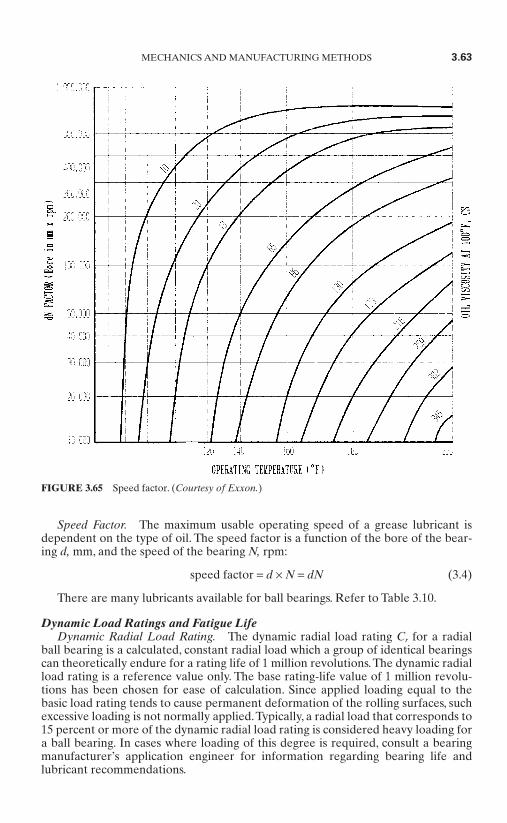
Speed Factor. The maximum usable operating speed of a grease lubricant isdependent on the type of oil. The speed factor is a function of the bore of the bear-ing d, mm, and the speed of the bearing N, rpm:
speed factor = d × N = dN (3.4)
There are many lubricants available for ball bearings. Refer to Table 3.10.
Dynamic Load Ratings and Fatigue LifeDynamic Radial Load Rating. The dynamic radial load rating Cr for a radial
ball bearing is a calculated, constant radial load which a group of identical bearingscan theoretically endure for a rating life of 1 million revolutions.The dynamic radialload rating is a reference value only. The base rating-life value of 1 million revolu-tions has been chosen for ease of calculation. Since applied loading equal to thebasic load rating tends to cause permanent deformation of the rolling surfaces, suchexcessive loading is not normally applied.Typically, a radial load that corresponds to15 percent or more of the dynamic radial load rating is considered heavy loading fora ball bearing. In cases where loading of this degree is required, consult a bearingmanufacturer’s application engineer for information regarding bearing life andlubricant recommendations.
MECHANICS AND MANUFACTURING METHODS 3.63
FIGURE 3.65 Speed factor. (Courtesy of Exxon.)
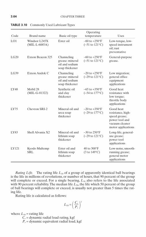
Rating Life. The rating life L10 of a group of apparently identical ball bearingsis the life in millions of revolutions, or number of hours, that 90 percent of the groupwill complete or exceed. For a single bearing, L10 also refers to the life associatedwith 90 percent reliability.The median life L50, the life which 50 percent of the groupof ball bearings will complete or exceed, is usually not greater than 5 times the rat-ing life.
Rating life is calculated as follows:
L10 = 3
where L10 = rating lifeCr = dynamic radial load rating, kgfPr = dynamic equivalent radial load, kgf
CrPr
3.64 CHAPTER THREE
TABLE 3.10 Commonly Used Lubricant Types
OperatingCode Brand name Basic oil type temperature Uses
LO1 Windsor L245X Ester oil −60 to +250°F Low-torque, low-(MIL-L-6085A) (−51 to 121°C) speed instrument
oil; rustpreventative
LG20 Exxon Beacon 325 Channeling −60 to +250°F General-purposegrease: mineral (−51 to 121°C) grease.oil and sodium soap thickener
LG39 Exxon Andok C Channeling −20 to +250°F Low migration;grease: mineral (−29 to 121°C) general officeoil and sodium equipmentsoap thickener applications
LY48 Mobil 28 Synthetic oil −65 to +350°F Good heat(MIL-G-81322) and clay (−54 to 177°C) resistance with
thickener low torque;throttle bodyapplications
LY75 Chevron SRI-2 Mineral oil and −20 to +350°F Good heaturea soap (−29 to 177°C) resistance, high-thickener speed grease;
power tool andvacuum cleanermotor applications
LY83 Shell Alvania X2 Mineral oil and −30 to 250°F Long-life, general-lithium soap (−29 to 121°C) use grease;thickener power tool
applications
LY121 Kyodo Multemp Ester oil and 40 to 300°F Low-noise, smooth-SRL lithium soap (3 to 149°C) running grease;
thickener general motorapplications
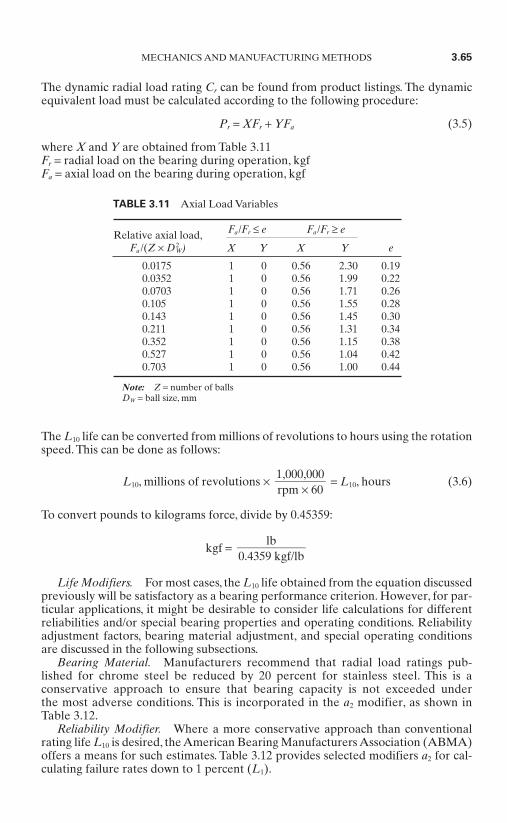
The dynamic radial load rating Cr can be found from product listings. The dynamicequivalent load must be calculated according to the following procedure:
Pr = XFr + YFa (3.5)
where X and Y are obtained from Table 3.11Fr = radial load on the bearing during operation, kgfFa = axial load on the bearing during operation, kgf
The L10 life can be converted from millions of revolutions to hours using the rotationspeed. This can be done as follows:
L10, millions of revolutions × = L10, hours (3.6)
To convert pounds to kilograms force, divide by 0.45359:
kgf =
Life Modifiers. For most cases, the L10 life obtained from the equation discussedpreviously will be satisfactory as a bearing performance criterion. However, for par-ticular applications, it might be desirable to consider life calculations for differentreliabilities and/or special bearing properties and operating conditions. Reliabilityadjustment factors, bearing material adjustment, and special operating conditionsare discussed in the following subsections.
Bearing Material. Manufacturers recommend that radial load ratings pub-lished for chrome steel be reduced by 20 percent for stainless steel. This is a conservative approach to ensure that bearing capacity is not exceeded under the most adverse conditions. This is incorporated in the a2 modifier, as shown inTable 3.12.
Reliability Modifier. Where a more conservative approach than conventionalrating life L10 is desired, the American Bearing Manufacturers Association (ABMA)offers a means for such estimates. Table 3.12 provides selected modifiers a2 for cal-culating failure rates down to 1 percent (L1).
lb0.4359 kgf/lb
1,000,000rpm × 60
MECHANICS AND MANUFACTURING METHODS 3.65
TABLE 3.11 Axial Load Variables
Fa/Fr ≤ e Fa/Fr ≥ e
X Y X Y
0.0175 1 0 0.56 2.30 0.190.0352 1 0 0.56 1.99 0.220.0703 1 0 0.56 1.71 0.260.105 1 0 0.56 1.55 0.280.143 1 0 0.56 1.45 0.300.211 1 0 0.56 1.31 0.340.352 1 0 0.56 1.15 0.380.527 1 0 0.56 1.04 0.420.703 1 0 0.56 1.00 0.44
Note: Z = number of ballsDW = ball size, mm
Relative axial load,Fa /(Z × D2
W) e

Other Life Adjustments. The conventional rating life often has to be modified asa consequence of application abnormalities, whether they be intentional orunknown. Seldom are loads ideally applied. The following conditions all have thepractical effect of modifying the ideal, theoretical rating life L10.
Vibration and/or shock-impact loads Angular misalignment High-speed effects Operation at elevated temperatures Fits Internal design
Oscillatory Service Life. Frequently, ball bearings do not operate with one ringrotating unidirectionally. Instead, they execute a partial revolution, reverse motion,and then repeat this cycle, most often in a uniform manner. Efforts to forecast a reli-able fatigue life by simply relating oscillation rate to an “equivalent” rotationalspeed are invalid. The actual fatigue life of bearings operating in the oscillatorymode is governed by four factors: applied load, angle of oscillation, rate of oscilla-tion, and lubricant.
Lubricant Life. In many instances a bearing’s effective life is governed by thelubricant’s life. This is usually the case where applications involve very light loadsand/or very slow speeds.
With light loads and/or slow speeds, the conventional fatigue-life forecast will beunrealistically high. The lubricant’s ability to provide sufficient film strength is sus-tained only for a limited time. This is governed by the following factors:
Quality and Quantity of the lubricant in the bearing Environmental conditions (i.e., ambient temperature, area cleanliness) The load-speed cycle
3.11.8 Static Capacity
Static Radial Load Rating. The static radial load rating Cor is the radial loadwhich a nonrotating ball bearing will support without damage, continuing to providesatisfactory performance and life.
The static radial load rating is dependent on the maximum contact stress betweenthe balls and either of the two raceways. The load ratings shown were calculated in
3.66 CHAPTER THREE
TABLE 3.12 Reliability Versus Material LifeModifier a2
Required reliability, % Ln Chrome DD
90 L10 1.00 0.5095 L5 0.62 0.3196 L4 0.53 0.2797 L3 0.44 0.2298 L2 0.33 0.1799 L1 0.21 0.11
Value of a2
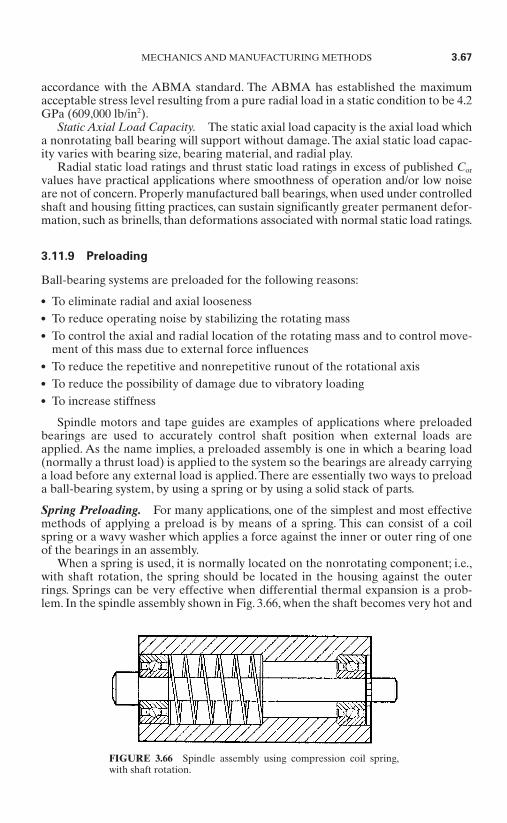
accordance with the ABMA standard. The ABMA has established the maximumacceptable stress level resulting from a pure radial load in a static condition to be 4.2GPa (609,000 lb/in2).
Static Axial Load Capacity. The static axial load capacity is the axial load whicha nonrotating ball bearing will support without damage. The axial static load capac-ity varies with bearing size, bearing material, and radial play.
Radial static load ratings and thrust static load ratings in excess of published Cor
values have practical applications where smoothness of operation and/or low noiseare not of concern. Properly manufactured ball bearings, when used under controlledshaft and housing fitting practices, can sustain significantly greater permanent defor-mation, such as brinells, than deformations associated with normal static load ratings.
3.11.9 Preloading
Ball-bearing systems are preloaded for the following reasons:
To eliminate radial and axial looseness To reduce operating noise by stabilizing the rotating mass To control the axial and radial location of the rotating mass and to control move-
ment of this mass due to external force influences To reduce the repetitive and nonrepetitive runout of the rotational axis To reduce the possibility of damage due to vibratory loading To increase stiffness
Spindle motors and tape guides are examples of applications where preloadedbearings are used to accurately control shaft position when external loads areapplied. As the name implies, a preloaded assembly is one in which a bearing load(normally a thrust load) is applied to the system so the bearings are already carryinga load before any external load is applied. There are essentially two ways to preloada ball-bearing system, by using a spring or by using a solid stack of parts.
Spring Preloading. For many applications, one of the simplest and most effectivemethods of applying a preload is by means of a spring. This can consist of a coilspring or a wavy washer which applies a force against the inner or outer ring of oneof the bearings in an assembly.
When a spring is used, it is normally located on the nonrotating component; i.e.,with shaft rotation, the spring should be located in the housing against the outerrings. Springs can be very effective when differential thermal expansion is a prob-lem. In the spindle assembly shown in Fig. 3.66, when the shaft becomes very hot and
MECHANICS AND MANUFACTURING METHODS 3.67
FIGURE 3.66 Spindle assembly using compression coil spring,with shaft rotation.
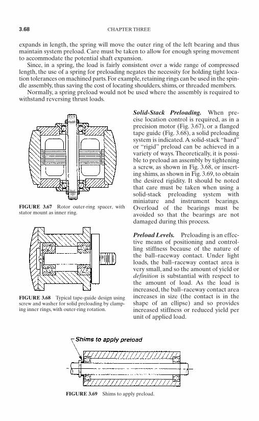
expands in length, the spring will move the outer ring of the left bearing and thusmaintain system preload. Care must be taken to allow for enough spring movementto accommodate the potential shaft expansion.
Since, in a spring, the load is fairly consistent over a wide range of compressedlength, the use of a spring for preloading negates the necessity for holding tight loca-tion tolerances on machined parts. For example, retaining rings can be used in the spin-dle assembly, thus saving the cost of locating shoulders, shims, or threaded members.
Normally, a spring preload would not be used where the assembly is required towithstand reversing thrust loads.
Solid-Stack Preloading. When pre-cise location control is required, as in aprecision motor (Fig. 3.67), or a flangedtape guide (Fig. 3.68), a solid preloadingsystem is indicated. A solid-stack “hard”or “rigid” preload can be achieved in avariety of ways. Theoretically, it is possi-ble to preload an assembly by tighteninga screw, as shown in Fig. 3.68, or insert-ing shims, as shown in Fig. 3.69, to obtainthe desired rigidity. It should be notedthat care must be taken when using asolid-stack preloading system withminiature and instrument bearings.Overload of the bearings must beavoided so that the bearings are notdamaged during this process.
Preload Levels. Preloading is an effec-tive means of positioning and control-ling stiffness because of the nature ofthe ball–raceway contact. Under lightloads, the ball–raceway contact area isvery small, and so the amount of yield ordefinition is substantial with respect tothe amount of load. As the load isincreased, the ball–raceway contact areaincreases in size (the contact is in theshape of an ellipse) and so providesincreased stiffness or reduced yield perunit of applied load.
3.68 CHAPTER THREE
FIGURE 3.67 Rotor outer-ring spacer, withstator mount as inner ring.
FIGURE 3.68 Typical tape-guide design usingscrew and washer for solid preloading by clamp-ing inner rings, with outer-ring rotation.
FIGURE 3.69 Shims to apply preload.
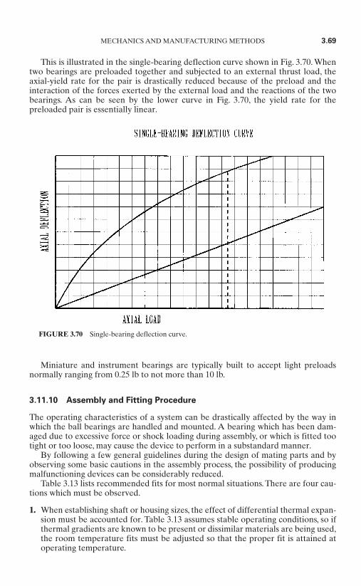
This is illustrated in the single-bearing deflection curve shown in Fig. 3.70. Whentwo bearings are preloaded together and subjected to an external thrust load, theaxial-yield rate for the pair is drastically reduced because of the preload and theinteraction of the forces exerted by the external load and the reactions of the twobearings. As can be seen by the lower curve in Fig. 3.70, the yield rate for thepreloaded pair is essentially linear.
Miniature and instrument bearings are typically built to accept light preloadsnormally ranging from 0.25 lb to not more than 10 lb.
3.11.10 Assembly and Fitting Procedure
The operating characteristics of a system can be drastically affected by the way inwhich the ball bearings are handled and mounted. A bearing which has been dam-aged due to excessive force or shock loading during assembly, or which is fitted tootight or too loose, may cause the device to perform in a substandard manner.
By following a few general guidelines during the design of mating parts and byobserving some basic cautions in the assembly process, the possibility of producingmalfunctioning devices can be considerably reduced.
Table 3.13 lists recommended fits for most normal situations. There are four cau-tions which must be observed.
1. When establishing shaft or housing sizes, the effect of differential thermal expan-sion must be accounted for. Table 3.13 assumes stable operating conditions, so ifthermal gradients are known to be present or dissimilar materials are being used,the room temperature fits must be adjusted so that the proper fit is attained atoperating temperature.
MECHANICS AND MANUFACTURING METHODS 3.69
FIGURE 3.70 Single-bearing deflection curve.
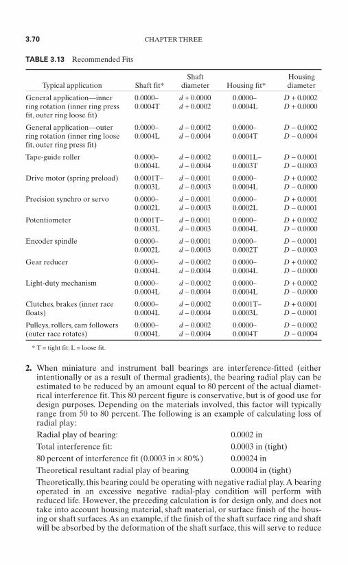
2. When miniature and instrument ball bearings are interference-fitted (eitherintentionally or as a result of thermal gradients), the bearing radial play can beestimated to be reduced by an amount equal to 80 percent of the actual diamet-rical interference fit. This 80 percent figure is conservative, but is of good use fordesign purposes. Depending on the materials involved, this factor will typicallyrange from 50 to 80 percent. The following is an example of calculating loss ofradial play:Radial play of bearing: 0.0002 inTotal interference fit: 0.0003 in (tight)80 percent of interference fit (0.0003 in × 80%) 0.00024 inTheoretical resultant radial play of bearing 0.00004 in (tight)Theoretically, this bearing could be operating with negative radial play.A bearingoperated in an excessive negative radial-play condition will perform withreduced life. However, the preceding calculation is for design only, and does nottake into account housing material, shaft material, or surface finish of the hous-ing or shaft surfaces.As an example, if the finish of the shaft surface ring and shaftwill be absorbed by the deformation of the shaft surface, this will serve to reduce
3.70 CHAPTER THREE
TABLE 3.13 Recommended Fits
Shaft HousingTypical application Shaft fit* diameter Housing fit* diameter
General application—inner 0.0000– d + 0.0000 0.0000– D + 0.0002ring rotation (inner ring press 0.0004T d + 0.0002 0.0004L D + 0.0000fit, outer ring loose fit)
General application—outer 0.0000– d − 0.0002 0.0000– D − 0.0002ring rotation (inner ring loose 0.0004L d − 0.0004 0.0004T D − 0.0004fit, outer ring press fit)
Tape-guide roller 0.0000– d − 0.0002 0.0001L– D − 0.00010.0004L d − 0.0004 0.0003T D − 0.0003
Drive motor (spring preload) 0.0001T– d − 0.0001 0.0000– D + 0.00020.0003L d − 0.0003 0.0004L D − 0.0000
Precision synchro or servo 0.0000– d − 0.0001 0.0000– D + 0.00010.0002L d − 0.0003 0.0002L D − 0.0001
Potentiometer 0.0001T– d − 0.0001 0.0000– D + 0.00020.0003L d − 0.0003 0.0004L D − 0.0000
Encoder spindle 0.0000– d − 0.0001 0.0000– D − 0.00010.0002L d − 0.0003 0.0002T D − 0.0003
Gear reducer 0.0000– d − 0.0002 0.0000– D + 0.00020.0004L d − 0.0004 0.0004L D − 0.0000
Light-duty mechanism 0.0000– d − 0.0002 0.0000– D + 0.00020.0004L d − 0.0004 0.0004L D − 0.0000
Clutches, brakes (inner race 0.0000– d − 0.0002 0.0001T– D + 0.0001floats) 0.0004L d − 0.0004 0.0003L D − 0.0001
Pulleys, rollers, cam followers 0.0000– d − 0.0002 0.0000– D − 0.0002(outer race rotates) 0.0004L d − 0.0004 0.0004T D − 0.0004
* T = tight fit; L = loose fit.
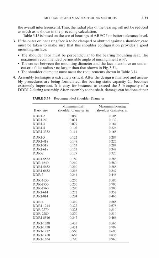
the overall interference fit.Thus, the radial play of the bearing will not be reducedas much as is shown in the preceding calculation.
Table 3.13 is based on the use of bearings of ABEC 5 or better tolerance level.3. If the outer or inner ring face is to be clamped or abutted against a shoulder, care
must be taken to make sure that this shoulder configuration provides a goodmounting surface: The shoulder face must be perpendicular to the bearing mounting seat. The
maximum recommended permissible angle of misalignment is 1⁄4°. The corner between the mounting diameter and the face must have an under-
cut or a fillet radius r no larger than that shown in Fig. 3.51. The shoulder diameter must meet the requirements shown in Table 3.14.
4. Assembly technique is extremely critical.After the design is finalized and assem-bly procedures are being formulated, the bearing static capacity Cor becomesextremely important. It is easy, for instance, to exceed the 3-lb capacity of aDDRI-2 during assembly.After assembly to the shaft, damage can be done either
MECHANICS AND MANUFACTURING METHODS 3.71
TABLE 3.14 Recommended Shoulder Diameter
Minimum shaft Maximum housing Basic size shoulder diameter, in shoulder diameter, in
DDRI-2 0.060 0.105DDRI-21⁄2 0.071 0.132DDRI-3 0.079 0.164DDRI-4 0.102 0.226DDRI-3332 0.114 0.168
DDRI-5 0.122 0.284DDRI-418 0.148 0.226DDRI-518 0.153 0.284DDRI-618 0.153 0.347DDR-2 0.179 0.325
DDRI-5532 0.180 0.288DDR-1640 0.210 0.580DDRI-5632 0.210 0.288DDRI-6632 0.216 0.347DDR-3 0.244 0.446
DDR-1650 0.250 0.580DDR-1950 0.250 0.700DDR-1960 0.290 0.700DDRI-614 0.272 0.352DDRI-814 0.284 0.466
DDR-4 0.310 0.565DDRI-1214 0.322 0.678DDR-2270 0.325 0.810DDR-2280 0.370 0.810DDRI-8516 0.347 0.466
DDRI-1038 0.435 0.565DDRI-1438 0.451 0.799DDRI-1212 0.560 0.690DDRI-1458 0.665 0.835DDRI-1634 0.790 0.960

by direct pressure or by moment load while the bearing and shaft subassembly isbeing forced into a tight housing. A few simple calculations will underscore thispoint.
Adequate fixturing should always be provided for handling and assemblingprecision bearings. This fixturing must be designed so that when assembling thebearing to the shaft, force is applied only to the inner ring, and when assemblinginto the housing, force is applied only to the outer ring. Further, the fixturingmust preclude the application of any moment or shock loads which would betransmitted through the bearing. Careful attention to this assembly phase of thetotal design effort can prevent many problems and provide savings when pro-duction starts.
3.12 SLEEVE BEARINGS*
There are two common types of sleeve bearings. The rigid steel-backed babbit bear-ing and the self-aligning sintered bearing are shown in Figs. 3.71a and 3.71b, respec-tively. Babbit is a soft alloy of tin and lead that has a low coefficient of friction. It isbacked by a thin steel material to give the bearing rigidity. A wick notch and oilgroove are normally formed in the bearing when it is manufactured.
Rigid bearings are pressed into the end frame and burnished or machined to size.An oil reservoir surrounds the bearing. If the bearing is a sintered bronze or sinterediron type, the oil wicks through the pores in the bearing by capillary action and pro-vides lubricant to the shaft. In the case of steel-backed babbitt bearings, a wick ofsome type must be placed in a hole in the bearing so that oil from the reservoir canreach the shaft.
Self-aligning sintered bearings are held against the end frame by a retainingspring. Oil wicks from the oil reservoir through the pores in the material as in therigid sintered bearings. Ball bearings are used where it is necessary to limit radialshaft play or where high side loads are expected in the application. These are themost costly bearings. Rigid bearings are used where moderate side loads areexpected. Self-aligning bearings are used where light side loads are expected andstarting friction has to be minimized.
The self-aligning bearing is the lowest-cost device, but it also carries the lowestload. The rigid sleeve bearing costs somewhat more than the self-aligning bearing,but it can carry a heavier load. Ball bearings can carry a much heavier load, but theyalso cost 5 to 20 times more than a sleeve bearing.
The most common shaft and bearing system consists of a steel shaft in a sinteredbronze bearing. As a general rule, the harder the shaft, the longer the life of the sys-tem. Generally, Rockwell C scale 35 to 55 is a good range. Stainless steels are accept-able, except that the 300 series should be avoided with bronze bearings becauseexcessive wear will result. When using bronze bearings, the load speed and shaft-to-bearing clearance must be considered. The pressure velocity factor PV must be cal-culated to ensure that it is within the rating of the material selected. Bronze is ratedat PV = 50,000.
PV = (3.7)πDN
12w
LD
3.72 CHAPTER THREE
* Section contributed by William H. Yeadon, Yeadon Engineering Services, PC
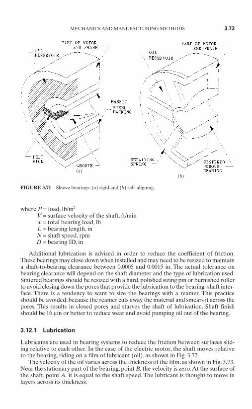
where P = load, lb/in2
V = surface velocity of the shaft, ft/minw = total bearing load, lbL = bearing length, inN = shaft speed, rpmD = bearing ID, in
Additional lubrication is advised in order to reduce the coefficient of friction.These bearings may close down when installed and may need to be resized to maintaina shaft-to-bearing clearance between 0.0005 and 0.0015 in. The actual tolerance onbearing clearance will depend on the shaft diameter and the type of lubrication used.Sintered bearings should be resized with a hard, polished sizing pin or burnished rollerto avoid closing down the pores that provide the lubrication to the bearing–shaft inter-face. There is a tendency to want to size the bearings with a reamer. This practiceshould be avoided, because the reamer cuts away the material and smears it across thepores. This results in closed pores and starves the shaft of lubrication. Shaft finishshould be 16 µin or better to reduce wear and avoid pumping oil out of the bearing.
3.12.1 Lubrication
Lubricants are used in bearing systems to reduce the friction between surfaces slid-ing relative to each other. In the case of the electric motor, the shaft moves relativeto the bearing, riding on a film of lubricant (oil), as shown in Fig. 3.72.
The velocity of the oil varies across the thickness of the film, as shown in Fig. 3.73.Near the stationary part of the bearing, point B, the velocity is zero.At the surface ofthe shaft, point A, it is equal to the shaft speed. The lubricant is thought to move inlayers across its thickness.
MECHANICS AND MANUFACTURING METHODS 3.73
FIGURE 3.71 Sleeve bearings: (a) rigid and (b) self-aligning.
(a)(b)
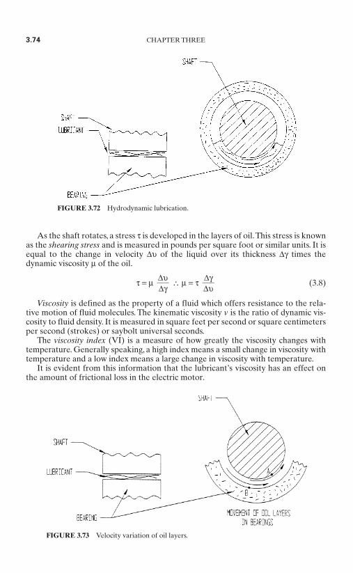
As the shaft rotates, a stress τ is developed in the layers of oil.This stress is knownas the shearing stress and is measured in pounds per square foot or similar units. It isequal to the change in velocity ∆υ of the liquid over its thickness ∆γ times thedynamic viscosity µ of the oil.
τ = µ ∴ µ = τ (3.8)
Viscosity is defined as the property of a fluid which offers resistance to the rela-tive motion of fluid molecules. The kinematic viscosity v is the ratio of dynamic vis-cosity to fluid density. It is measured in square feet per second or square centimetersper second (strokes) or saybolt universal seconds.
The viscosity index (VI) is a measure of how greatly the viscosity changes withtemperature. Generally speaking, a high index means a small change in viscosity withtemperature and a low index means a large change in viscosity with temperature.
It is evident from this information that the lubricant’s viscosity has an effect onthe amount of frictional loss in the electric motor.
∆γ∆υ
∆υ∆γ
3.74 CHAPTER THREE
FIGURE 3.72 Hydrodynamic lubrication.
FIGURE 3.73 Velocity variation of oil layers.
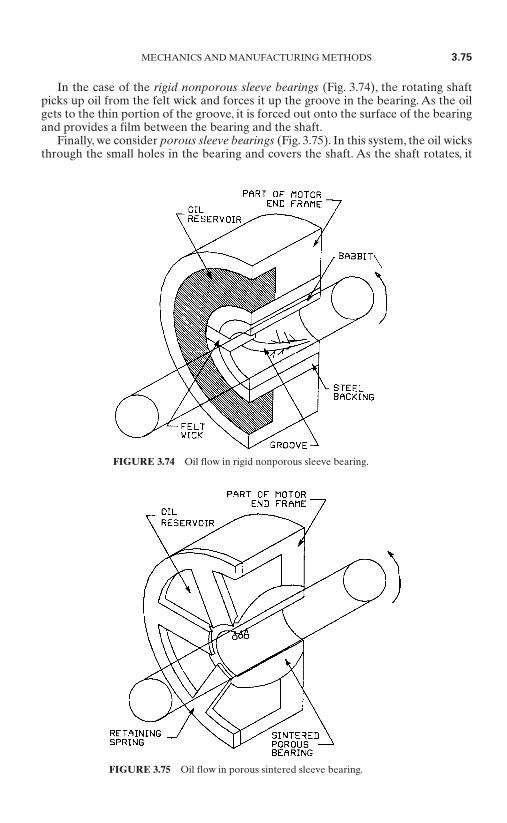
In the case of the rigid nonporous sleeve bearings (Fig. 3.74), the rotating shaftpicks up oil from the felt wick and forces it up the groove in the bearing. As the oilgets to the thin portion of the groove, it is forced out onto the surface of the bearingand provides a film between the bearing and the shaft.
Finally, we consider porous sleeve bearings (Fig. 3.75). In this system, the oil wicksthrough the small holes in the bearing and covers the shaft. As the shaft rotates, it
MECHANICS AND MANUFACTURING METHODS 3.75
FIGURE 3.74 Oil flow in rigid nonporous sleeve bearing.
FIGURE 3.75 Oil flow in porous sintered sleeve bearing.
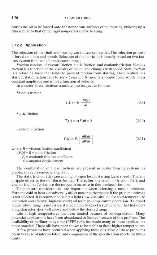
causes the oil to be forced onto the nonporous surfaces of the bearing, building up afilm similar to that of the rigid nonporous sleeve bearing.
3.12.2 Application
The selection of the shaft and bearing were discussed earlier. The selection processis based on loads and speeds. Selection of the lubricant is usually based on two fac-tors, system friction and temperature range.
Friction consists of viscous friction, static friction, and coulomb friction. Viscousfriction is a function of the viscosity of the oil and changes with speed. Static frictionis a retarding force that tends to prevent motion from starting. Once motion hasstarted, static friction falls to zero. Coulomb friction is a torque force which has aconstant amplitude and is not a function of velocity.
In a motor, these frictions translate into torques as follows:
Viscous friction
Tv(t) = B (3.9)
Static friction
Ts(t) = ±(Fs)θ = 0 (3.10)
Coulomb friction
Tc(t) = Fc (3.11)
where B = viscous friction coefficient(Fs)θ = 0 = static friction
Fc = coulomb friction coefficientθ = angular displacement
The combination of these frictions are present in motor bearing systems, asgraphically represented in Fig. 3.76.
The static friction Ts(t) causes a high torque loss at starting (zero speed).There isa ripple effect as the oil film is formed. Thereafter, the coulomb friction Tc(t), andviscous friction Tv(t) cause the torque to increase in this nonlinear fashion.
Temperature considerations are important when selecting a motor lubricant.Extreme cold or heat can adversely affect motor performance if the proper lubricantis not selected. It is common to select a light (low-viscosity) oil for cold-temperatureoperation and a heavy (high-viscosity) oil for high-temperature operation. If a broadtemperature range is necessary, it is common to select a synthetic oil that has oper-ating characteristics well above and below the desired range.
Life at high temperatures has been limited because of oil degradation. Manypotential applications have been abandoned or limited because of this problem. Theavailability of perfluoropolyether (PFPE) oils has made many of these applicationsmore practical.These oils have been shown to be stable at these higher temperatures.
A few problems have occurred when applying these oils. Most of these problemsoccur because of interpretation and comparison of the specification sheets for lubri-cants.
dθ/dtdθ/dt
dθ(t)
dt
3.76 CHAPTER THREE
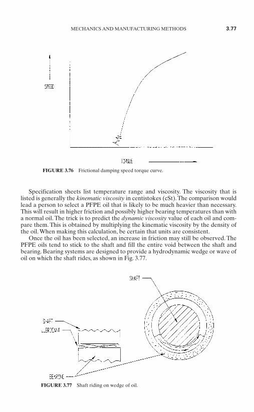
Specification sheets list temperature range and viscosity. The viscosity that islisted is generally the kinematic viscosity in centistokes (cSt).The comparison wouldlead a person to select a PFPE oil that is likely to be much heavier than necessary.This will result in higher friction and possibly higher bearing temperatures than witha normal oil. The trick is to predict the dynamic viscosity value of each oil and com-pare them. This is obtained by multiplying the kinematic viscosity by the density ofthe oil. When making this calculation, be certain that units are consistent.
Once the oil has been selected, an increase in friction may still be observed. ThePFPE oils tend to stick to the shaft and fill the entire void between the shaft andbearing. Bearing systems are designed to provide a hydrodynamic wedge or wave ofoil on which the shaft rides, as shown in Fig. 3.77.
MECHANICS AND MANUFACTURING METHODS 3.77
FIGURE 3.76 Frictional damping speed torque curve.
FIGURE 3.77 Shaft riding on wedge of oil.
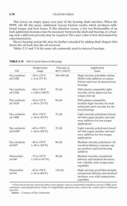
This leaves an empty space over part of the bearing–shaft interface. When thePFPE oils fill this space, additional viscous friction results, which produces addi-tional torque and heat losses. If this situation occurs, a few ten-thousandths of aninch additional clearance may be necessary between the shaft and bearing, or a bear-ing with a different porosity may be required. The exact value is best determined byexperimentation.
Sleeve-bearing system life may be further extended by adding shaft slingers thatthrow the oil back into the oil reservoir.
Tables 3.15 and 3.16 list some oils commonly used in sintered bearings.
3.78 CHAPTER THREE
TABLE 3.15 Oils Used in Sintered Bearings
Temperature Viscosity at Application Oil range 40°C (104°F) focus
Nye synthetic −20 to 125°C 500–560 cSt High-viscosity polyalpha olefineoil 310B (−4 to 257°F) (PAO) with additives to reduce
friction and wear in sintered ironbearings.
Nye synthetic −60 to 120°C 20 cSt PAO, plastic-compatible, light-oil 132B (−148 to 248°F) viscosity oil for improved low-
torque start-up
Nye synthetic −40 to 125°C 60 cSt PAO, plastic-compatible,oil 181B (−40 to 257°F) medium-high-viscosity oil; most
commonly used viscosity for sin-tered bearings
Nye synthetic −40 to 150°C 35 cSt Light-viscosity polyolester-basedoil 188B (−40 to 302°F) oil with copper pacifier and anti-
wear additives for low-torqueapplications
Nye synthetic −40 to 150°C 35 cSt Light-viscosity polyolester-basedoil 634B* (−40 to 302°F) oil with copper pacifier and anti-
wear additives for low-torqueapplications
Nye synthetic −40 to 150°C 60 cSt Medium-viscosity polyolester oil;oil 605* (−40 to 302°F) excellent lubricity; contains cop-
per pacifiers and load-bearingadditives
Fluoroether −75 to 225°C 90 cSt Medium viscosity, exceptionaloil 490 (−103 to 437°F) lubricity and chemical inertness,
low volatility, wide temperaturecapability
Fluoroether −65 to 250°C 150 cSt High viscosity, good film strength,oil 491 (−85 to 482°F) exceptional lubricity and chemical
inertness, very wide temperaturecapability.
* Ester-based oils may adversely affect some plastics, such as acrylonitrile-butadiene-styrene (ABS), poly-carbonates, and polyphenylene oxides. If compatibility questions arise, contact the vendor prior to lubricantselection.
Source: Courtesy of Nye Lubricants.

3.13 PROCESS CONTROL IN COMMUTATORFUSING*
Fusing has been found to be the most critical process in electric motor manufactur-ing. This is particularly true for the new generation of asbestos-free, high-speedmotors.
This section describes how to evaluate fusing results, the fusing process, theeffects of commutator design and construction on the fusing process, and improve-ments to fusing-machine technology for improved process control.
Historically, the fusing process has been the single greatest source of rejects inarmature manufacture. Thus, it is one essential area on which efforts to improvetechnology must be focused.
The process of fusing tang commutators is the focus for analysis here, althoughmany of the observations, methods, and conclusions are also valid for fusing slotcommutators. The electrical, mechanical, and thermal characteristics of fusing thetwo types of commutators remain the same, but the observations on the geometryand the thermal and electrical phenomena inside the tang are different for the slottype of commutator.
MECHANICS AND MANUFACTURING METHODS 3.79
TABLE 3.16 Krytox PFPE Lubricants for Sintered Bearings
GPL oil grade 103 104 105
XP oil grade (antirust) 1A3 1A4 1A5
ISO oil grade 32 68 150
Estimated useful range°C −60 to 154 −51 to 179 −36 to 204°F −76 to 310 −60 to 355 −33 to 400
Oil viscosity, cSt20°C (68°F) 80 180 55040°C (104°) 30 60 160100°C (212°) 5 9 18204°C (400°) — — 3
Oil viscosity index 121 124 134
Oil pour point°C −60 −51 −36°F −76 −60 −33
Maximum oil volatility,% in 22 h
@ 66°C (150°F) 1 1 1@ 121°C (250°F) 7 3 2@ 204°C (400°F) — — 10
Note: The GPL series oils are unadditized and are recommended for use innonferrous applications. If rusting could occur, the XP oils should be used. TheXP oils have a soluble antirust additive.
Source: Courtesy DuPont Corporation.
* Section contributed by Axis SPA.
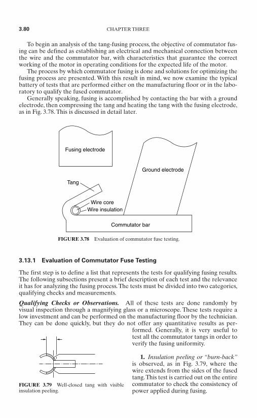
To begin an analysis of the tang-fusing process, the objective of commutator fus-ing can be defined as establishing an electrical and mechanical connection betweenthe wire and the commutator bar, with characteristics that guarantee the correctworking of the motor in operating conditions for the expected life of the motor.
The process by which commutator fusing is done and solutions for optimizing thefusing process are presented. With this result in mind, we now examine the typicalbattery of tests that are performed either on the manufacturing floor or in the labo-ratory to qualify the fused commutator.
Generally speaking, fusing is accomplished by contacting the bar with a groundelectrode, then compressing the tang and heating the tang with the fusing electrode,as in Fig. 3.78. This is discussed in detail later.
3.13.1 Evaluation of Commutator Fuse Testing
The first step is to define a list that represents the tests for qualifying fusing results.The following subsections present a brief description of each test and the relevanceit has for analyzing the fusing process. The tests must be divided into two categories,qualifying checks and measurements.
Qualifying Checks or Observations. All of these tests are done randomly byvisual inspection through a magnifying glass or a microscope. These tests require alow investment and can be performed on the manufacturing floor by the technician.They can be done quickly, but they do not offer any quantitative results as per-
formed. Generally, it is very useful totest all the commutator tangs in order toverify the fusing uniformity.
1. Insulation peeling or “burn-back”is observed, as in Fig. 3.79, where thewire extends from the sides of the fusedtang.This test is carried out on the entirecommutator to check the consistency ofpower applied during fusing.
3.80 CHAPTER THREE
Fusing electrode
Tang
Wire coreWire insulation
Ground electrode
Commutator bar
FIGURE 3.78 Evaluation of commutator fuse testing.
FIGURE 3.79 Well-closed tang with visibleinsulation peeling.

2. Bar oxidation gives an indication of the heat stress caused to the commutatorduring fusing. This test may also be used to gauge the consistency of energy applica-tion during fusing, although it is heavily affected by external conditions such as thepresence of cooling airflow.
3. Tang roughness gives an indication of the wear status of the electrode. Thetechnician observes the top of the tang for pitting or scars. This occurs because thetungsten fusing-electrode surface breaks down due to the heat and pressure applied.
4. Observation of the tang closing checks for air gaps between the tang and thebar. A perfect closure, as in Fig. 3.83, prevents accumulation of extraneous materialunder the tang that would otherwise insulate the wire from the bar.
5. Subjective test of resistance to mechanical stress—stress the tang transverselyor vertically, as shown in Fig. 3.80, to check the mechanical connection to the bar.When the joining force is reached the two parts separate, emitting an easily audiblesnap. When the tang is not connected, no sound is heard.
6. Visual test of the tang impression on the bar—the degree of mechanical cohesioncan be observed by lifting the tang in order to observe its impression on the bar.A well-marked impression does not always correspond to a good mechanical cohesion, whilethe presence of oxidation under the tang is a clear indication of noncohesion.
7. Visual test of the wire impression on the tang and bar—normally, with a goodfuse, you can clearly see the impression of the wire under the tang and on the bar.The copper of the tang and bar surrounding the wire is a good indication that thewire has made good surface contact with the tang and the bar.
Measurements. These tests are generally carried out either in the laboratory ordirectly on the production line. The benefit of testing on the line is that it gives themanufacturer the ability to create a database for quality control and for trackingserial parts, and it guarantees that each part has been measured against a set of tol-erances.
1. Electrical continuity testing checks for electrical continuity between the com-mutator bars. It requires a simple and low-cost equipment setup; however, it doesnot distinguish poor from good electrical connections.
2. Fuse resistance testing is carried out on a commercial machine in the produc-tion line to measure each tang’s fuse resistance.The test permits accurate evaluationof the electrical connection across the wire and bar.
MECHANICS AND MANUFACTURING METHODS 3.81
t
FIGURE 3.80 Resistance to mechanical stress.

3. Measurement of final tang thickness indicates whether the force and energyused during fusing have been maintained within required tolerances.
4. Measured resistance to mechanical stress testing, a more accurate measure-ment of tang-to-bar cohesion, can be obtained by using a dynamometer to measurethe breaking load. In high-rpm applications, the armature is rotated to very highspeed in order to accomplish a further check for bar lift.
5. Wire-squeezing testing evaluates the result of the motion of the tang duringfusing.This test is destructive, because it requires that the tang be opened to measurethe thickness of the wire. Normally, the optimal decrease in the wire diameter(minor diameter of ellipse-shaped wire) is 15 to 40 percent. Reduction of the wirediameter within this range ensures good wire stability while also ensuring that thewire is not excessively weakened.
6. Measurement of the commutator temperature, carried out immediately afterfusing, indicates the thermal stress on the commutator. Generally, the commutatormanufacturer indicates a maximum allowable temperature. This test has becomevery important with asbestos-free commutators.
3.13.2 Fusing Process
Basically, the fusing process requires compressing and heating by applying currentflow through the parts that need to be fused.
The following is a description of the most important stages that occur during fus-ing (see Fig. 3.81):
3.82 CHAPTER THREE
PD
P
FIGURE 3.81 Stages 1 to 3 of fusing.

Stage 1. A properly dimensioned ground electrode is brought into contact withthe commutator bar without damaging the commutator, by means of a pneumaticcylinder.Stage 2. The fusing electrode is brought into contact with the commutator tang(Fig. 3.81) without excessively bending the tang. In physical terms, this requiresthat a well-proportioned ratio between the kinetic energy of the fusing head andthe mechanical strength of the tang and the commutator be achieved. Since themass of the fusing head can be reduced only within certain limits, the speed of the electrode becomes an important control variable in efforts to minimize thekinetic energy. In order to accomplish a low-speed approach in first contactingthe tang, low electrode force must initially be applied. Then the force should begradually increased to reach the preset values as required during the current-flowphase.Stage 3. The electrode applies a resultant force F on the tang (Fig. 3.81), which,due to the increasing surface contact of the electrode, moves until it becomes bal-anced by the opposing deformation of the tang.When this balance is reached, theelectrode stops moving and current should be applied. In particular, the geome-try of the tang, the size of the wire, the wire position beneath the tang, and thesharpening angle of the electrode determine this balance position.Stage 4. At the beginning of the power application, the current flows throughthe tang in a lengthwise direction (Fig. 3.82).The tang begins to heat at the elbow,the tang portion enveloping the wire, where the current density is higher. In thisfirst stage, the wire insulating material is eliminated. The insulation evaporateseasily because the tang is still open. When the temperature rises, the mechanical
MECHANICS AND MANUFACTURING METHODS 3.83
1,Stage 2 3 4 5 6
7
8
6
5
4
3
2
1
0
-1
–2 1.0
0
100
200P
F
X
I
300
400
500
600
700(N)
750
86 173 259 350(ms)
2.0
3.0
4.0
5.0
6.0
7.0
8.0
9.0
10.0
(mm)(KA)(KW)
FIGURE 3.82 Stage 4 of fusing.

characteristics of the copper change; therefore, the tang becomes more plastic inits elbow (this is the point with the highest temperature), and the tang continuesto close until it contacts the bar (Fig. 3.83).
Stage 5. Once the tip of the tang contacts the bar, the current starts passingthrough the tang in a transverse direction. As the contact area with the barincreases, the current through this area also increases, thereby reducing the cur-rent density in the tang elbow. At this point the heat is mostly applied to the tipof the tang (Fig. 3.84).
Stage 6. Once the current supply is terminated, the electrode continues to applyforce to the tang for a preset time. During this time the temperature decreasesand mechanical cohesion is completed (Fig. 3.85). Variables which influencecohesion are typically the electrode force, the time for applying the cohesionforce, and the presence of forced cooling of the tang (e.g., by using low-temperature airflow).
Importance of the Wire and the Commutator in the Fusing Process. The geomet-ric characteristics and the composition of the commutator and the winding wire are
3.84 CHAPTER THREE
P
I
FIGURE 3.83 Stage 4 of fusing.
P
II
FIGURE 3.84 Stage 5 of fusing.
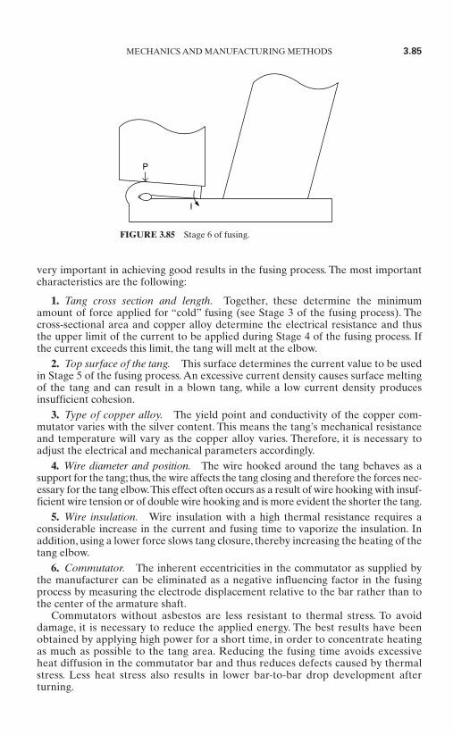
very important in achieving good results in the fusing process. The most importantcharacteristics are the following:
1. Tang cross section and length. Together, these determine the minimumamount of force applied for “cold” fusing (see Stage 3 of the fusing process). Thecross-sectional area and copper alloy determine the electrical resistance and thusthe upper limit of the current to be applied during Stage 4 of the fusing process. Ifthe current exceeds this limit, the tang will melt at the elbow.
2. Top surface of the tang. This surface determines the current value to be usedin Stage 5 of the fusing process. An excessive current density causes surface meltingof the tang and can result in a blown tang, while a low current density producesinsufficient cohesion.
3. Type of copper alloy. The yield point and conductivity of the copper com-mutator varies with the silver content. This means the tang’s mechanical resistanceand temperature will vary as the copper alloy varies. Therefore, it is necessary toadjust the electrical and mechanical parameters accordingly.
4. Wire diameter and position. The wire hooked around the tang behaves as asupport for the tang; thus, the wire affects the tang closing and therefore the forces nec-essary for the tang elbow.This effect often occurs as a result of wire hooking with insuf-ficient wire tension or of double wire hooking and is more evident the shorter the tang.
5. Wire insulation. Wire insulation with a high thermal resistance requires aconsiderable increase in the current and fusing time to vaporize the insulation. Inaddition, using a lower force slows tang closure, thereby increasing the heating of thetang elbow.
6. Commutator. The inherent eccentricities in the commutator as supplied bythe manufacturer can be eliminated as a negative influencing factor in the fusingprocess by measuring the electrode displacement relative to the bar rather than tothe center of the armature shaft.
Commutators without asbestos are less resistant to thermal stress. To avoiddamage, it is necessary to reduce the applied energy. The best results have beenobtained by applying high power for a short time, in order to concentrate heatingas much as possible to the tang area. Reducing the fusing time avoids excessiveheat diffusion in the commutator bar and thus reduces defects caused by thermalstress. Less heat stress also results in lower bar-to-bar drop development afterturning.
MECHANICS AND MANUFACTURING METHODS 3.85
P
I
FIGURE 3.85 Stage 6 of fusing.
7. Bar and tang geometry. The relationship between tang mass mt and bar massmb are correlated to the temperature T of the commutator bar at the end of fusing,as follows:
T = K (3.12)
where K = temperature dependent coefficient
If the tang is small compared to the bar, fusing can be done with lower thermal stresson the commutator.
3.13.3 Improvements to Fusing-Machine Technology
1. During the fusing process, current distribution in various portions of the tangvaries considerably, as has been described previously. This variation results in signif-icant variations in the associated electrical resistance rt of the tang. The heat Qapplied to the tang by means of current i can be expressed as follows:
Q = rt (t) ∗ i2(t)dt (3.13)
If heat application occurs by regulating only the RMS value of the current i, thevariations in resistance rt will cause unwanted variations in heat Q. To avoid this, forobtaining more precise heat application, it is necessary to regulate the power Papplied during fusing.
Q = P(t)dt = v(t) ∗ i(t)dt (3.14)
For this power regulation, and to obtain fusing in a sufficiently short time, medium-frequency dc inverters are the most adequate electrical power supply equipment thatcan be used. Normally, fusing cycle times are completed in 70 to 150 ms. DC medium-frequency inverters (1 to 1.2 kHz) regulate using closed-loop feedback every 415 to500 µs. Line-frequency equipment regulates every 8,000 µs. Considering, for example,a fusing done in 72 ms, which corresponds to a little more than 4 cycles in Americanline frequency, line-frequency regulation is likely to be inadequate most of the time.
2. During the fusing process, preset electrode force profiles need to be applied toprecisely control tang closure and to distribute the heat correctly in the various por-tions of the tang. To achieve force application in this way with necessary controlaccuracy, the fusing system should use closed-loop force control.
3. Quality fusing requires that the machine be designed and built to guaranteehigh repeatability and reliability. In particular, the fusing machine needs to haveadequate cooling of the electrode to maintain consistent working temperature,design construction that guarantees accurate alignment of the electrode with thetang, and provisions for quick electrode replacement by the operator without affect-ing the precision and repeatability of the machine’s performance.
3.13.4 Conclusions
Today, fusing-machine technology allows reliable and consistent fusing of commuta-tors using low energy. In particular, this is required to process modern high-speed
m1mt + mb
3.86 CHAPTER THREE

motors having asbestos-free commutators. Since the fusing process is also signifi-cantly affected by the commutator and wire-insulation characteristics, it should becarefully considered in new motor design.
3.14 ARMATURE AND ROTOR BALANCING*
Unbalance is defined as the uneven distribution of mass about the axis of rotation ofa rotating body. Unbalance is the direct result of fixed or variable sources. Fixed-source unbalance is caused by nonsymmetrical design or manufacture, while variable-source unbalance is due to operational factors such as distortion or shifting ofcomponents by centripetal force. The result of the unbalance is a net centripetalforce at the bearings, and this, in turn, causes vibrations in the system. Balancing isthe procedure used to reduce the unbalance level to a level at which the resultingvibration is low enough that operation of the equipment is not impaired.
To define an unbalanced condition, four items must be identified. Unbalancemagnitude U is the result of an unbalanced mass m located at a specific radius r. The
location is defined first in terms of theangular location in degrees from a zeroreference location, and finally by theaxial location of the unbalance relativeto the support bearings. In order to cor-rect for unbalance in a rotor, you mustidentify these four parameters, repre-sented graphically in Fig. 3.86. For thistype of rotor, a single unbalance correc-tion is adequate. For wider rotors, theresulting effects of multiple unbalanceshave to be resolved with two correctionsat separate axial locations. This sectionexplains these variations and providesguidelines to enable selection of appro-priate production balancing methods.
3.14.1 Constituents of a RotatingObject
Shaft Axis. The shaft axis (centerline)of the rotor, shown in Fig. 3.87, is definedby the centerlines of the support bear-
ings. The shaft axis may or may not contain the center of mass. Parts are designed torotate about the shaft axis of a rotor, which is also the rotational axis.
Principal Axis. The principal axis always includes the center of gravity (or masscenter) of the part. By definition, the mass of the rotor is evenly distributed about
MECHANICS AND MANUFACTURING METHODS 3.87
* Section contributed by Larry C. Anderson, American Hoffman Corporation.
FIGURE 3.86 Location of unbalanced mass.Unbalance magnitude U is the result of unbal-anced mass m located at angle 45° on radius r.

the principal axis. Unbalanced rotorsattempt to rotate about the principalaxis, but are restrained to rotate aboutthe shaft axis by their support bearings.The vibrations and bearing loads due tothe unbalance are directly proportionalto this misalignment. Figure 3.87 pre-sents an exaggerated illustration of howthe mass of a rotor can be offset on theshaft axis. Note that the rotor is rotatingaround the shaft axis, but ideally, thecenter or principal axis is the true centerof the rotor.
Center of Mass. The center of mass isgenerally considered to be at the geo-metric center of an object. In fact, the
center of mass, or inertia, is the location of symmetric mass distribution and is notthe same as the location of the geometric center.
In an unbalanced rotor, the principalaxis does not coincide with the shaftaxis. When a rotor is balanced, the prin-cipal axis coincides with the shaft axis, asshown in Fig. 3.88.
A rotor will always attempt to rotateabout its principal axis but is con-strained by the support bearings, whichforce it to rotate about the shaft axis.Displacement of these two axes resultsin bearing loads and vibration which isdirectly proportional to the misalign-ment.
A rotating object is composed ofcomponents that have mass and flexibil-ity and which absorb and dissipateenergy when subjected to internal dis-turbances; the result is a unique pattern
of motions called rotor response. The rotor response at operating speed directlyaffects the object’s sensitivity to unbalance. Speeds close to resonant frequenciesrequire much closer balance tolerances due to the increased rotor-response charac-teristics. The effects of speed and resonance are explained in more detail later.
3.14.2 Characteristics of Static and Dynamic Unbalance
Static Unbalance. Static unbalance is classified as single-plane unbalance, mean-ing that it is represented by a single vector quantity and corrected by a single cor-rection mass applied opposite to the unbalance location and in the axial plane of themass center of the rotor. When there is no way to add (or remove) mass in the sameplane as the unbalance, the correction can be split into two equal corrections at theends of the rotor to achieve the same results. Static unbalance can be detected bynonrotational equipment and is characterized by the fact that the principal axis isdisplaced parallel to the shaft axis, as shown in Fig. 3.89.
3.88 CHAPTER THREE
FIGURE 3.87 Misalignment of center of mass.
FIGURE 3.88 Balanced rotor with even massdistribution.
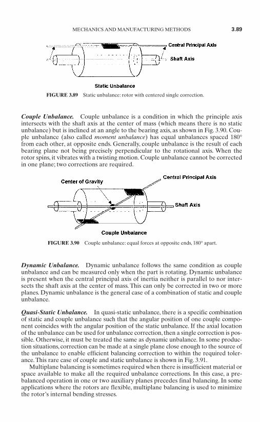
Couple Unbalance. Couple unbalance is a condition in which the principle axisintersects with the shaft axis at the center of mass (which means there is no staticunbalance) but is inclined at an angle to the bearing axis, as shown in Fig. 3.90. Cou-ple unbalance (also called moment unbalance) has equal unbalances spaced 180°from each other, at opposite ends. Generally, couple unbalance is the result of eachbearing plane not being precisely perpendicular to the rotational axis. When therotor spins, it vibrates with a twisting motion. Couple unbalance cannot be correctedin one plane; two corrections are required.
Dynamic Unbalance. Dynamic unbalance follows the same condition as coupleunbalance and can be measured only when the part is rotating. Dynamic unbalanceis present when the central principal axis of inertia neither is parallel to nor inter-sects the shaft axis at the center of mass. This can only be corrected in two or moreplanes. Dynamic unbalance is the general case of a combination of static and coupleunbalance.
Quasi-Static Unbalance. In quasi-static unbalance, there is a specific combinationof static and couple unbalance such that the angular position of one couple compo-nent coincides with the angular position of the static unbalance. If the axial locationof the unbalance can be used for unbalance correction, then a single correction is pos-sible. Otherwise, it must be treated the same as dynamic unbalance. In some produc-tion situations, correction can be made at a single plane close enough to the source ofthe unbalance to enable efficient balancing correction to within the required toler-ance. This rare case of couple and static unbalance is shown in Fig. 3.91.
Multiplane balancing is sometimes required when there is insufficient material orspace available to make all the required unbalance corrections. In this case, a pre-balanced operation in one or two auxiliary planes precedes final balancing. In someapplications where the rotors are flexible, multiplane balancing is used to minimizethe rotor’s internal bending stresses.
MECHANICS AND MANUFACTURING METHODS 3.89
FIGURE 3.89 Static unbalance: rotor with centered single correction.
FIGURE 3.90 Couple unbalance: equal forces at opposite ends, 180° apart.

From a theoretical standpoint, the aim is always to achieve a zero-unbalance con-dition. In practice, the requirement is to reduce the unbalance to a point at which theunbalance forces have a negligible or nonharmful effect on part operation. Produc-tion situations require careful attention to the tolerances and correction proceduresto achieve minimum cycle times with required service life and performance.
3.14.3 Effects of Increased Speed
The unbalance of a rotor does not change with speed but is solely due to its mass dis-tribution about the bearing axis. The centripetal force generated by the unbalanceincreases with the square of the rotational speed change; therefore, the balance tol-erance has to be determined for the maximum operating speed of the rotor.
The operating speed and bearing forces determine the bearing life, so the unbal-ance must be limited to achieve the required operating lifetime. The intensity ofvibration (acceleration) must be limited to avoid noise and vibration apparent to theoperator, which is proportional to the velocity of the vibration, which requires thatthe balancing tolerance be tightened as speed increases.
It is normally not necessary to balance a rotor at operating speed. In fact, theaim should always be to balance at the lowest practical speed. A lower balancingspeed is preferable for a number of reasons. Faster speeds require a longer time toramp up and ramp down and also require stronger, stiffer tooling arrangementsand tighter clamping of the rotor assembly, which in turn increases the risk of dis-tortion or damage. Lower speeds assure safety for the operator and require lesselaborate machine guards. However, the performance of the balancing machinetransducers and instrumentation improves with increasing speed due to thegreater signal levels from the increase in centripetal force, illustrated in Fig. 3.92.
3.90 CHAPTER THREE
FIGURE 3.91 Quasi-static unbalance: combination of static andcouple unbalance.
FIGURE 3.92 Effects of centripetal force on mass.
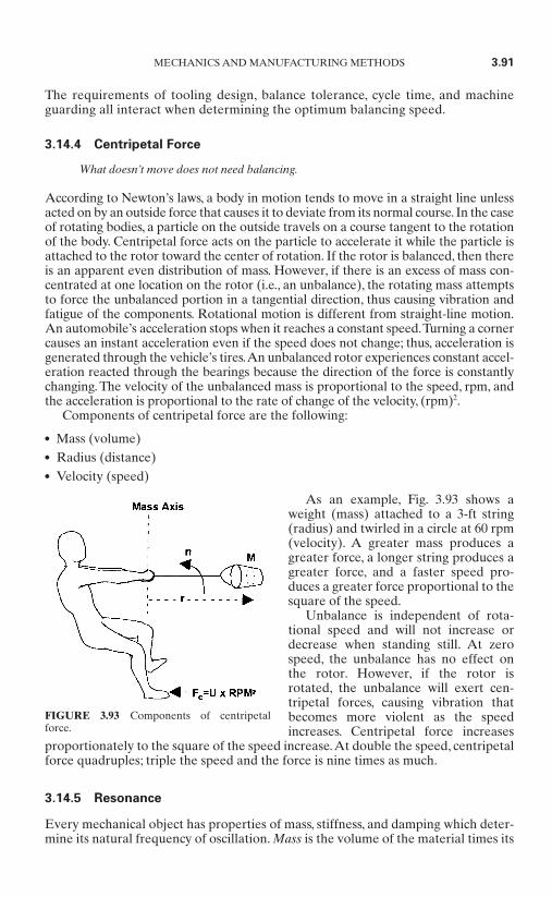
The requirements of tooling design, balance tolerance, cycle time, and machineguarding all interact when determining the optimum balancing speed.
3.14.4 Centripetal Force
What doesn’t move does not need balancing.
According to Newton’s laws, a body in motion tends to move in a straight line unlessacted on by an outside force that causes it to deviate from its normal course. In the caseof rotating bodies, a particle on the outside travels on a course tangent to the rotationof the body. Centripetal force acts on the particle to accelerate it while the particle isattached to the rotor toward the center of rotation. If the rotor is balanced, then thereis an apparent even distribution of mass. However, if there is an excess of mass con-centrated at one location on the rotor (i.e., an unbalance), the rotating mass attemptsto force the unbalanced portion in a tangential direction, thus causing vibration andfatigue of the components. Rotational motion is different from straight-line motion.An automobile’s acceleration stops when it reaches a constant speed.Turning a cornercauses an instant acceleration even if the speed does not change; thus, acceleration isgenerated through the vehicle’s tires.An unbalanced rotor experiences constant accel-eration reacted through the bearings because the direction of the force is constantlychanging. The velocity of the unbalanced mass is proportional to the speed, rpm, andthe acceleration is proportional to the rate of change of the velocity, (rpm)2.
Components of centripetal force are the following:
Mass (volume) Radius (distance) Velocity (speed)
As an example, Fig. 3.93 shows aweight (mass) attached to a 3-ft string(radius) and twirled in a circle at 60 rpm(velocity). A greater mass produces agreater force, a longer string produces agreater force, and a faster speed pro-duces a greater force proportional to thesquare of the speed.
Unbalance is independent of rota-tional speed and will not increase ordecrease when standing still. At zerospeed, the unbalance has no effect onthe rotor. However, if the rotor isrotated, the unbalance will exert cen-tripetal forces, causing vibration thatbecomes more violent as the speedincreases. Centripetal force increases
proportionately to the square of the speed increase.At double the speed, centripetalforce quadruples; triple the speed and the force is nine times as much.
3.14.5 Resonance
Every mechanical object has properties of mass, stiffness, and damping which deter-mine its natural frequency of oscillation. Mass is the volume of the material times its
MECHANICS AND MANUFACTURING METHODS 3.91
FIGURE 3.93 Components of centripetalforce.
density. Stiffness depends on the elasticity of the material. Damping is a measure ofthe ability of the system to dissipate vibratory energy.
The natural frequency is directly proportional to the stiffness and inversely pro-portional to the mass. This is the frequency at which the object will tend to self-vibrate when rung by an impact.
Materials such as soft rubber have a high level of damping and a low stiffnessand tend to absorb and dissipate vibration. Most hard materials have a higher stiff-ness and a lower level of damping. The damping factor determines the rate ofenergy loss to the surroundings. The damping factor is a nonlinear parameter andchanges with speed. For a given structure, there is a frequency at which the damp-ing factor approaches zero and therefore very little vibration energy is absorbed.
Resonance and critical speeds are frequencies that are governed by natural fre-quencies, damping, and vibratory forces. A resonance is a condition in a structure inwhich the frequency of a vibratory force, such as mass unbalance, is equal to a natu-ral frequency of the system. If the vibratory force is caused by a rotating part, theresonance is called a critical speed.
A structure or object can be excited by one or more vibratory forces. Vibratoryforces can be caused by various factors, including design, installation, manufacture, andwear, or the force can have a single constant frequency, as occurs with mass unbalance.
A rotational assembly with any finite unbalance acts as a vibration exciter andwill produce a force as it is rotated. This is called the excitation frequency. When thenatural frequency and the excitation frequency coincide, a state of resonance is saidto exist. As rotational speed approaches the resonant frequency, the effects of theforce increases. At resonant frequency, vibration amplitudes can become very large.If the rate of speed is close to the resonant frequency, a very low level of unbalancecan still generate unacceptable vibration amplitudes.
As rotational speed reaches the resonant frequency, the support structure willvibrate directly with the exciting force (phase shift = 0°). As the speed increasesnearer to resonance, the phase begins to shift until at resonance there is a 90° phaseshift. As the rotational speed continues to increase, the phase continues to changeuntil it reaches opposition (phase shift = 180°).
Balancing requires an exact knowledge of both the magnitude and the location ofthe unbalance, and so balancing speeds close to resonance are to be avoided.A smallspeed change will cause a large change in both the amount and the angle of the mea-sured signal, and the results will be incorrect.
Sometimes equipment is designed to emphasize the resonant frequency.A tuningfork or piano string produces strong vibrations at the resonant frequency, which isbeneficial; however, this is not the case with a stiff rotor, where the exact oppositecondition is needed.
Vibrations that have large amplitudes can cause early fatigue failure. The energyexpended by such vibrations causes significant power loss and speed reduction. Inaddition, noise levels from the vibration may be irritating to the operator as well asdetrimental to the components surrounding the bearings.
It follows from this that as speeds and densities increase, keeping resonance awayfrom the operating speed is a crucial part of the assembly designer’s job. Ensuringthat balancing speeds and tool design avoid resonance is a crucial part of thebalancing-machine and tooling manufacturers’ jobs.
3.14.6 Correcting for Unbalance
Correction can be accomplished by adding, removing, or moving material.The phys-ical properties of the rotating device must be analyzed to determine the best method
3.92 CHAPTER THREE

of correction. Methods of correcting unbalance in a production environment are asfollows:
Material removal by milling Material removal by drilling Material removal by cutting or clipping molded dimples Material addition by weighted epoxies Material addition by UV-cured epoxies Adjustments to molds and dies Relocation of the shaft axis (mass centering)
Whenever the unbalanced mass prohibits correction at a specified angle (as in anarea where a correction cannot be made or the amount of added weight will not allfit on a designated angle), correction can be made by vectoring adjacent angles orcomponents to implement a correction. The total unbalance is split into two vectorsfor adjacent components. For high levels of unbalance, it may be necessary to vectormore than two components and use more than two weights.
When designing a rotor, it is important to estimate the maximum initial unbal-ance and to make allowance for adding sufficient correction mass at an appropriatelocation. The balance tolerance must be used to determine the amount of weightthat can be added and the increments of weight in order to have enough resolutionto bring the rotor into tolerance in one or two attempts.
A correction plane is determined by evaluating where mass can be added withoutaffecting the mechanical operation of the rotor. Once a correction plane is selected, acorrection method can be chosen. If weight is to be added, the weight mass and num-ber of locations must be determined. Larger weight sizes permit more correction butlimit the minimum value that can be achieved. If adhesive weights are to be used, aridge, indentation, or roughened area is needed to prevent creep under loading.
Generally, weight removal is the preferred means of balancing small armaturesand assemblies. Correction by drilling was the original preferred method; however
this inefficient means of correction hasbeen replaced almost exclusively bymilling. Two of the most popular opera-tions available on balancing machinesare contour milling and component slotmilling. Contour milling, shown in Fig.3.94, involves the use of special millingcutters which are designed for the pro-file or curve of the stack. Material isremoved at the exact polar location ofthe unbalance. Contour milling allowsfor larger amounts of unbalance in onecut, which reduces the cycle time of the
balancing process. This is ideally suited for manufacturers of armatures with thesame stack diameter but different numbers of poles, or for balancing rotors with askewed stack.
Component slot milling is used when accuracy is required. Grooves machinedinto the centers of adjacent pole tips are milled either by a V-mill or slot cutter. Fig-ure 3.95 shows this method of correction. The balancing machine calculates theunbalance vector using two or more components and determines how deep a cutshould be made and whether the mill should transverse to adequately remove the
MECHANICS AND MANUFACTURING METHODS 3.93
FIGURE 3.94 Contour mill cut.

unbalance mass. This type of millingshould be used in cases in which the lam-inations are too thin to allow adequatematerial removal through profile con-tour milling. This condition is exempli-fied by the edges of the pole tipsbecoming “feathered” because of a lackof material.
Weight removal offers several advan-tages over weight addition, especiallyfor high-production applications: it isfaster, it can be more accurately con-trolled, and it is easier to automate.However, hand milling has its advan-tages also. Whenever the armature has
areas not easily accessed (such as fans), rotating components, or raised components,the armature or rotating assembly has to be corrected by hand. This is also true inlow-production situations where automation is not justified.
To minimize cycle times it is important to achieve tolerance in the smallest num-ber of steps. The accuracy of the balancing machine must be adequate to give a pre-cise readout of the required correction needed. Production can benefit greatly whenthe balancer instrumentation can convert the basic unbalance data into specific cor-rection masses at specific locations so the operator has step-by-step guidance.
3.14.7 Types of Balancing Machines
Balancing machines are used to determine the unbalance of a rotor in terms of boththe magnitude of the mass unbalance and its angular position, in one or more planes.The system must support the rotor, spin it at a predetermined rpm, measure theforces that occur, and display the results in values useful for unbalance correction.Automated machines may even index the rotor to the required angle for a correc-tion and add correction weights or remove unbalance mass.
For production balancing, the machine is typically set up to provide some indica-tion of whether the rotor is within tolerance. If the rotor is out of tolerance, precisereadout of the angle and amount are required. Hard-bearing balancing machinestypically respond directly to the rotor unbalance and are not affected by speed.Theyare also permanently calibrated.
Since the force that a given amount of unbalance exerts at a given speed is alwaysthe same, the output from the sensing elements attached to the balancing machine isdirectly proportional to the unbalance in the rotor. The variation of the sensing ele-ment with balancing speed is known, and compensation for speed variations is auto-matic. The output is not influenced by bearing mass, rotor mass, or inertia, so that apermanent relationship between unbalance and sensing element output can beestablished, and the display of unbalance amounts can be directly in terms of therequired correction mass.The output is affected by looseness or by a lack of stiffnessin the tooling, and it is important that the tooling locates the housing (or bearing car-rier) rigidly and without distortion.
The most popular method of obtaining a reference signal by which to determinethe phase angle of the unbalance signal is through the use of an optical sensor thatdetects a reference mark representing zero degrees somewhere on the circumfer-ence of the rotor.A light source is reflected off the surface and picked up by the sen-sor. Through timing circuitry, an angle is established using the zero reference mark.
3.94 CHAPTER THREE
FIGURE 3.95 V-mill or slot mill cutter.
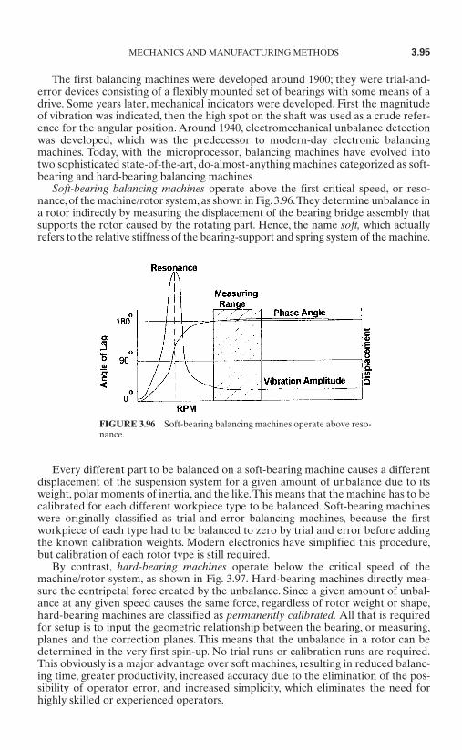
The first balancing machines were developed around 1900; they were trial-and-error devices consisting of a flexibly mounted set of bearings with some means of adrive. Some years later, mechanical indicators were developed. First the magnitudeof vibration was indicated, then the high spot on the shaft was used as a crude refer-ence for the angular position. Around 1940, electromechanical unbalance detectionwas developed, which was the predecessor to modern-day electronic balancingmachines. Today, with the microprocessor, balancing machines have evolved intotwo sophisticated state-of-the-art, do-almost-anything machines categorized as soft-bearing and hard-bearing balancing machines
Soft-bearing balancing machines operate above the first critical speed, or reso-nance, of the machine/rotor system, as shown in Fig. 3.96.They determine unbalance ina rotor indirectly by measuring the displacement of the bearing bridge assembly thatsupports the rotor caused by the rotating part. Hence, the name soft, which actuallyrefers to the relative stiffness of the bearing-support and spring system of the machine.
Every different part to be balanced on a soft-bearing machine causes a differentdisplacement of the suspension system for a given amount of unbalance due to itsweight, polar moments of inertia, and the like.This means that the machine has to becalibrated for each different workpiece type to be balanced. Soft-bearing machineswere originally classified as trial-and-error balancing machines, because the firstworkpiece of each type had to be balanced to zero by trial and error before addingthe known calibration weights. Modern electronics have simplified this procedure,but calibration of each rotor type is still required.
By contrast, hard-bearing machines operate below the critical speed of themachine/rotor system, as shown in Fig. 3.97. Hard-bearing machines directly mea-sure the centripetal force created by the unbalance. Since a given amount of unbal-ance at any given speed causes the same force, regardless of rotor weight or shape,hard-bearing machines are classified as permanently calibrated. All that is requiredfor setup is to input the geometric relationship between the bearing, or measuring,planes and the correction planes. This means that the unbalance in a rotor can bedetermined in the very first spin-up. No trial runs or calibration runs are required.This obviously is a major advantage over soft machines, resulting in reduced balanc-ing time, greater productivity, increased accuracy due to the elimination of the pos-sibility of operator error, and increased simplicity, which eliminates the need forhighly skilled or experienced operators.
MECHANICS AND MANUFACTURING METHODS 3.95
FIGURE 3.96 Soft-bearing balancing machines operate above reso-nance.
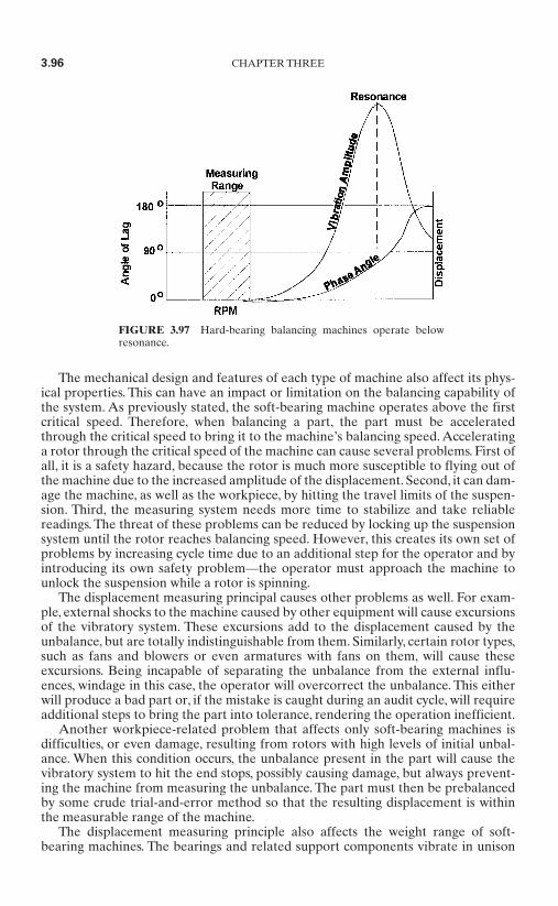
The mechanical design and features of each type of machine also affect its phys-ical properties. This can have an impact or limitation on the balancing capability ofthe system. As previously stated, the soft-bearing machine operates above the firstcritical speed. Therefore, when balancing a part, the part must be acceleratedthrough the critical speed to bring it to the machine’s balancing speed. Acceleratinga rotor through the critical speed of the machine can cause several problems. First ofall, it is a safety hazard, because the rotor is much more susceptible to flying out ofthe machine due to the increased amplitude of the displacement. Second, it can dam-age the machine, as well as the workpiece, by hitting the travel limits of the suspen-sion. Third, the measuring system needs more time to stabilize and take reliablereadings. The threat of these problems can be reduced by locking up the suspensionsystem until the rotor reaches balancing speed. However, this creates its own set ofproblems by increasing cycle time due to an additional step for the operator and byintroducing its own safety problem—the operator must approach the machine tounlock the suspension while a rotor is spinning.
The displacement measuring principal causes other problems as well. For exam-ple, external shocks to the machine caused by other equipment will cause excursionsof the vibratory system. These excursions add to the displacement caused by theunbalance, but are totally indistinguishable from them. Similarly, certain rotor types,such as fans and blowers or even armatures with fans on them, will cause theseexcursions. Being incapable of separating the unbalance from the external influ-ences, windage in this case, the operator will overcorrect the unbalance. This eitherwill produce a bad part or, if the mistake is caught during an audit cycle, will requireadditional steps to bring the part into tolerance, rendering the operation inefficient.
Another workpiece-related problem that affects only soft-bearing machines isdifficulties, or even damage, resulting from rotors with high levels of initial unbal-ance. When this condition occurs, the unbalance present in the part will cause thevibratory system to hit the end stops, possibly causing damage, but always prevent-ing the machine from measuring the unbalance. The part must then be prebalancedby some crude trial-and-error method so that the resulting displacement is withinthe measurable range of the machine.
The displacement measuring principle also affects the weight range of soft-bearing machines. The bearings and related support components vibrate in unison
3.96 CHAPTER THREE
FIGURE 3.97 Hard-bearing balancing machines operate belowresonance.

with the rotor, adding to its mass. This parasitic mass reduces machine sensitivity bydamping or reducing the displacement of the vibratory system. As the weight of therotor approaches the weight of the parasitic mass of the machine, displacement ofthe bearing and, what is more important, of the transducers is reduced. This limitsthe low end of the weight capacity of the machine. This can be overcome by havingadditional sets of bearing supports with less parasitic mass, allowing smaller, lighterparts to be balanced. This raises the cost of the soft machine and adds yet anothercumbersome operation, limiting flexibility.
Hard-bearing machines use the entire bearing support as part of the spring sys-tem, eliminating parasitic mass altogether. Theoretically, hard-bearing machineshave no lower weight limit. In actuality, however, they are limited by the physicalsize of the workpiece.
There is one further physical limitation of soft-bearing machines that is related tothe type of workpiece to be balanced. This rotor type is classified as cantilevered oroverhung. Balancing these parts requires special care on both types of machines. Acantilevered workpiece on a horizontal type of balance machine causes a negativeload on the support furthest from the center of gravity (CG) of the part. On a hardmachine, a counter–roller bearing must be used to hold the part securely in themachine. Measuring is not affected since the thrust bearing roller assembly is part ofthe vibratory system. On some types of soft machines, a downward load is requiredto ensure proper displacement of the vibratory system. This downward force can becreated with an overhung part by special fixturing which holds the part so that theCG is between the bearing supports, creating a downward load on both supports.Asin the case of using special roller carriages for small parts to extend the design limi-tations of the soft suspension, this arrangement allows balancing overhung parts, butat additional cost and time.
Balancing on a soft-bearing machine also requires repeatability of the balancingspeed from run to run.The displacement of the suspension system on a soft machineis a function of the rotational speed.Therefore, it is essential that on subsequent runsthe balancing speed be identical to the speed at which the machine was calibrated. Itis clear from the preceding discussion that hard-bearing machines are the preferredchoice for applications where frequent changeover and maximum flexibility arerequired. However, hard-bearing balancing machines have also become the norm inindustries where the need for reliability and high-level accuracy outweigh all otherconsiderations.These would include aircraft engines, turbomachinery, and computerdisk drives, to name only a few. In general, hard-bearing balancing machines havebecome the industry standard for all types of balancing applications.
3.14.8 Measuring System Sensitivity
The capability of a measuring system is determined by its sensitivity, repeatability,and accuracy. It is a combination of the limitations of both the balancing machineitself and the intrinsic parameters of the rotor being measured.
The sensitivity of a balancing system is not the smallest display indication but thesmallest amount that can be accurately measured. Sensitivity is typically measuredin microinches.
The repeatability or precision of a system is the reproducibility of multiple mea-surements of the same part. For statistical evaluations, the repeatability test is car-ried out on a number of parts.
The accuracy of a system is the relation between the measured amount and theactual unbalance of the part.This is related to calibration of the system for a specific
MECHANICS AND MANUFACTURING METHODS 3.97
unbalance and linearity of the measurements with differing amounts of unbalance.The smaller the difference, the more accurate the system. Consistent readings are anindication of repeatability, not accuracy.
The question is “What is the least amount of unbalance that can be detected?”Rotor operating characteristics play an important factor in determining the sen-
sitivity of the machine. The initial unbalance, resonance, shaft concentricity andbearings of the rotor may limit the system. Bearing quality directly affects the noiselevel and therefore the signal-to-noise ratio of the unbalance signal. If the machinehas to deal with a high initial unbalance, the measuring range has to be high toavoid overranging. The balancing machine’s measuring range directly affects theamount of sensitivity. You can’t measure ounces accurately if the range of themachine is in tons.
To find the limits for the system, a rotor and several removable calibrationweights are needed. The rotor must have the capacity for mounting each of the cali-bration weights at several angular locations. The rotor should be balanced as closelyas practical before measuring each of the calibration weights in each position. Plot-ting each set of data should produce a sine wave, with the amplitude representingthe remaining unbalance and the average representing the mass of the calibrationweights.The average values indicate the linearity of the system, and the variations ofthe amplitude from the measured residual unbalance indicate the lower limits ofmachine measurement. Detailed analysis of accuracy is a subject in itself and isbeyond the scope of this handbook.
3.14.9 Tooling
Balance tooling is the cradle or work-holding device used to securely hold a partduring the unbalance measurement and correction processes. The tooling must sup-port and locate the rotor to ensure that the unbalance forces (signal) are transferredto the unbalance detection transducers. If the balance tooling does not repeat,locate, and clamp the rotor assembly, the result will be errors in amount, angle, andaxial distribution (for two-plane balance) of the unbalance measurement.
Balance tooling may include other functions, such as autoindexing, remoteangle, material addition/removal, and total indicated run-out (TIR), or contain thedrive source for rotating the part. The tooling should be securely fastened to themeasuring table or work supports on which the balancing operation is to be per-formed.
Typically, the armature will want to creep to one side or another while spinning.A stop or end thrust positioned so the armature shaft rides against it will maintainthe rotating armature in a set position. When adjusted correctly, the end thrust willnot affect the unbalance measurement of the rotor. Misalignment may cause restric-tion in the free spinning of the armature and/or bouncing in the cradle.
To ensure precision in any balancing operation, the rotor must be properly posi-tioned with respect to the work supports and correction planes. This is called refer-encing. To ensure the desired accuracy, the operator must make sure the part isprecisely located and rigidly supported.To make the rotor easier to load and unload,adjust the end thrust to allow the rotor to ride against it but also to compliment thepole sensors. A properly adjusted balancing cradle will ensure correct plane loca-tion, short load and unload times, and simple operation. Achieving these often con-tradictory requirements takes careful attention to detail.
The most advanced and accurate balancing machine is worthless if the tooling isnot adequate. A good reference for accurate unbalance measurements starts withperfected tooling.
3.98 CHAPTER THREE

3.15 BRUSH HOLDERS FOR SMALL MOTORS*
Brush holders are crucial components of the overall commutation system in brush-type direct-current motors. Brush holders play a key role in determining the overallperformance of the motor. When manufactured and installed properly, brush hold-ers serve the following functions:
Hold the carbon brush in place. Insulate the carbon brush and electrical system from the other conductive parts of
the motor. Serve a crucial function in aligning the brushes against the commutator at the cor-
rect angle. Provide an unobstructed channel so that the brushes can move freely up and down
to compensate for any commutator eccentricity. Maximize brush life, minimize brush noise or chatter, and maintain the integrity of
the electrical connections.
For these reasons, careful thought and consideration must be given to the design, useand application of the brush holder. This section gives an overview of the differentstyles of brush holders as well as application and design considerations. The sectionfocuses on brush holders designed for fractional-horsepower motors.
3.15.1 Different Styles of Brush Holders for Small Motors
Brush holders can be broadly categorized as either radial design or reaction design.Reaction-design brush holders establish the brush axis at an angle to the commuta-tor. Radial-design brush holders establish the brush axis at a right angle perpendicu-lar to the commutator. Within these categories, the particular design and size of abrush holder will depend on the size of the motor and the application for which themotor is intended. For small motors, the two principle physical designs are the cartridge-style brush holder, shown in Fig. 3.98, and the internal brush ring assembly.
MECHANICS AND MANUFACTURING METHODS 3.99
* Section contributed by John S. Bank, Phoenix Electric Manufacturing.
FIGURE 3.98 Photo-cartridge-style brush holder.
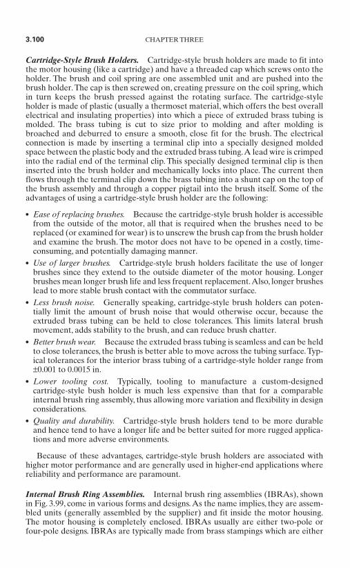
Cartridge-Style Brush Holders. Cartridge-style brush holders are made to fit intothe motor housing (like a cartridge) and have a threaded cap which screws onto theholder. The brush and coil spring are one assembled unit and are pushed into thebrush holder. The cap is then screwed on, creating pressure on the coil spring, whichin turn keeps the brush pressed against the rotating surface. The cartridge-styleholder is made of plastic (usually a thermoset material, which offers the best overallelectrical and insulating properties) into which a piece of extruded brass tubing ismolded. The brass tubing is cut to size prior to molding and after molding isbroached and deburred to ensure a smooth, close fit for the brush. The electricalconnection is made by inserting a terminal clip into a specially designed moldedspace between the plastic body and the extruded brass tubing.A lead wire is crimpedinto the radial end of the terminal clip. This specially designed terminal clip is theninserted into the brush holder and mechanically locks into place. The current thenflows through the terminal clip down the brass tubing into a shunt cap on the top ofthe brush assembly and through a copper pigtail into the brush itself. Some of theadvantages of using a cartridge-style brush holder are the following:
Ease of replacing brushes. Because the cartridge-style brush holder is accessiblefrom the outside of the motor, all that is required when the brushes need to bereplaced (or examined for wear) is to unscrew the brush cap from the brush holderand examine the brush. The motor does not have to be opened in a costly, time-consuming, and potentially damaging manner.
Use of larger brushes. Cartridge-style brush holders facilitate the use of longerbrushes since they extend to the outside diameter of the motor housing. Longerbrushes mean longer brush life and less frequent replacement.Also, longer brusheslead to more stable brush contact with the commutator surface.
Less brush noise. Generally speaking, cartridge-style brush holders can poten-tially limit the amount of brush noise that would otherwise occur, because theextruded brass tubing can be held to close tolerances. This limits lateral brushmovement, adds stability to the brush, and can reduce brush chatter.
Better brush wear. Because the extruded brass tubing is seamless and can be heldto close tolerances, the brush is better able to move across the tubing surface.Typ-ical tolerances for the interior brass tubing of a cartridge-style holder range from±0.001 to 0.0015 in.
Lower tooling cost. Typically, tooling to manufacture a custom-designedcartridge-style bush holder is much less expensive than that for a comparableinternal brush ring assembly, thus allowing more variation and flexibility in designconsiderations.
Quality and durability. Cartridge-style brush holders tend to be more durableand hence tend to have a longer life and be better suited for more rugged applica-tions and more adverse environments.
Because of these advantages, cartridge-style brush holders are associated withhigher motor performance and are generally used in higher-end applications wherereliability and performance are paramount.
Internal Brush Ring Assemblies. Internal brush ring assemblies (IBRAs), shownin Fig. 3.99, come in various forms and designs.As the name implies, they are assem-bled units (generally assembled by the supplier) and fit inside the motor housing.The motor housing is completely enclosed. IBRAs usually are either two-pole orfour-pole designs. IBRAs are typically made from brass stampings which are either
3.100 CHAPTER THREE

crimped or mounted (by screws or riv-ets) on a phenolic or plastic ring. A tor-sion spring is then mounted on aseparate stud located next to thestamping on the ring. This torsionspring applies pressure to the brush andkeeps it riding against the commutator.The electrical connection is madethrough a copper pigtail attached to thebrush, which is in turn attached toanother separate metal stud (eithermounted in the ring or as a part of thebrass stamping), on which a lead is fas-tened or soldered.
IBRAs are generally less expensivethan functionally equivalent cartridge-
style brush holders; however, they often present some design problems which the engineer must take into account when considering the end use of the motor.Once a particular design is tooled, design flexibility is limited since the stampinghas a seam, which can interfere with a smooth brush ride if not properly fitted and deburred. Brush dust can accumulate in the seam, which can result in arcing.Also, a stamping cannot hold as tight a tolerance as an extrusion. A typical toler-ance for the interior of a stamping is in the range of ±0.002 to 0.003 in. Also, brushreplacement is difficult, time-consuming, and potentially damaging since themotor must be disassembled to access the brushes. For these reasons, IBRAs areusually used in throwaway-type applications where the motor is replaced ratherthan repaired.
Another type of IBRA is the one which forms an integral part of the motor hous-ing itself. This is usually a single molded plastic part which provides several func-tions, such as holding a brush as well as forming the end bell. Pressure is applied tothe brush by either a torsion spring or a leaf assembly. This type of design is bettersuited for high-volume production, because the tooling to design and manufacturethis type of IBRA is expensive. In addition, once a particular design is tooled, mod-ification of the tooling is expensive. Also, in certain high-temperature applicationsthe plastic can melt or deform, thus causing the brush to hang up or stop in the brushchannel. Tolerances are also an issue since it is difficult and expensive to hold tighttolerances in a plastic brush cannel. The advantages of using an integrally moldedIBRA are the following:
The unit cost is relatively inexpensive. They can be used in small motors where space is a premium. Since they serve one or more functions, parts can be consolidated.
3.16.2 Application and Design Considerations
As previously noted, the particular size, style, and design of a brush holder willdepend on the size of the motor and the application for which the motor is intended.Required torque, voltage, and current will dictate the choice of grade of carbon forthe brush and the required spring pressure for the brush. Brush-size and motor-sizelimitations will in turn determine the size of the brush holder. Other considerationsinclude available space and life requirements.
MECHANICS AND MANUFACTURING METHODS 3.101
FIGURE 3.99 Internal brush ring assembly.
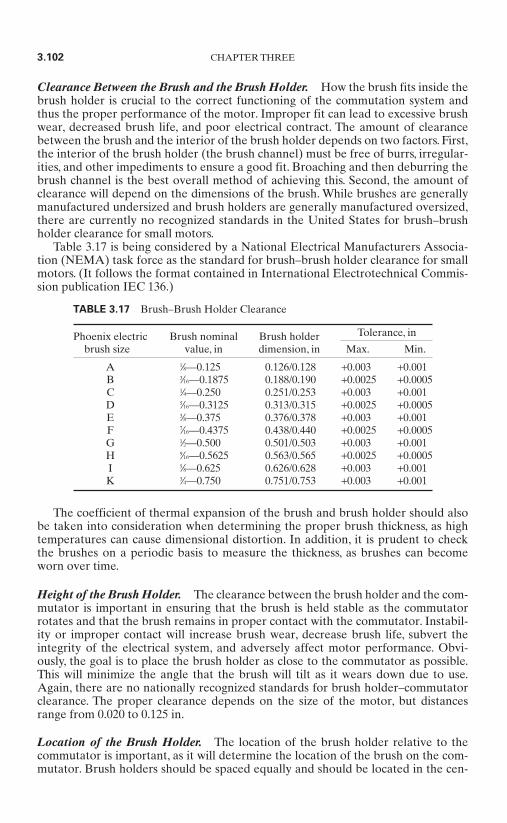
Clearance Between the Brush and the Brush Holder. How the brush fits inside thebrush holder is crucial to the correct functioning of the commutation system andthus the proper performance of the motor. Improper fit can lead to excessive brushwear, decreased brush life, and poor electrical contract. The amount of clearancebetween the brush and the interior of the brush holder depends on two factors. First,the interior of the brush holder (the brush channel) must be free of burrs, irregular-ities, and other impediments to ensure a good fit. Broaching and then deburring thebrush channel is the best overall method of achieving this. Second, the amount ofclearance will depend on the dimensions of the brush. While brushes are generallymanufactured undersized and brush holders are generally manufactured oversized,there are currently no recognized standards in the United States for brush–brushholder clearance for small motors.
Table 3.17 is being considered by a National Electrical Manufacturers Associa-tion (NEMA) task force as the standard for brush–brush holder clearance for smallmotors. (It follows the format contained in International Electrotechnical Commis-sion publication IEC 136.)
The coefficient of thermal expansion of the brush and brush holder should alsobe taken into consideration when determining the proper brush thickness, as hightemperatures can cause dimensional distortion. In addition, it is prudent to checkthe brushes on a periodic basis to measure the thickness, as brushes can becomeworn over time.
Height of the Brush Holder. The clearance between the brush holder and the com-mutator is important in ensuring that the brush is held stable as the commutatorrotates and that the brush remains in proper contact with the commutator. Instabil-ity or improper contact will increase brush wear, decrease brush life, subvert theintegrity of the electrical system, and adversely affect motor performance. Obvi-ously, the goal is to place the brush holder as close to the commutator as possible.This will minimize the angle that the brush will tilt as it wears down due to use.Again, there are no nationally recognized standards for brush holder–commutatorclearance. The proper clearance depends on the size of the motor, but distancesrange from 0.020 to 0.125 in.
Location of the Brush Holder. The location of the brush holder relative to thecommutator is important, as it will determine the location of the brush on the com-mutator. Brush holders should be spaced equally and should be located in the cen-
3.102 CHAPTER THREE
TABLE 3.17 Brush–Brush Holder Clearance
Phoenix electric Brush nominal Brush holderbrush size value, in dimension, in Max. Min.
A 1⁄8—0.125 0.126/0.128 +0.003 +0.001B 3⁄16—0.1875 0.188/0.190 +0.0025 +0.0005C 1⁄4—0.250 0.251/0.253 +0.003 +0.001D 5⁄16—0.3125 0.313/0.315 +0.0025 +0.0005E 3⁄8—0.375 0.376/0.378 +0.003 +0.001F 7⁄16—0.4375 0.438/0.440 +0.0025 +0.0005G 1⁄2—0.500 0.501/0.503 +0.003 +0.001H 9⁄16—0.5625 0.563/0.565 +0.0025 +0.0005I 5⁄8—0.625 0.626/0.628 +0.003 +0.001K 3⁄4—0.750 0.751/0.753 +0.003 +0.001
Tolerance, in
ter of the commutator. Typically, in a large two-pole application the brush holderswill be located on the side of the motor, so as to neutralize the effects of gravity. Inlarge four- (or more) pole applications, spring pressure on the brushes located on theunderside of the motor must be adjusted to compensate for gravity. The brushesshould also be aligned with the commutator bars.
Angle of the Brush Holder. As previously mentioned, brush holders can bemounted either radially to the commutator or in a reactionary relationship to thecommutator. A radially mounted brush holder is perpendicular (at a right angle) tothe commutator. The principal advantages of this type of design are that it is easierto remove and install the brush and that there is no loss of downward brush-springpressure. However, the brush tends to be less stable, and there is less brush contactwith the commutator.
In a reaction-type design, the holder is mounted at an angle to the commutator.This type of design can be either leading (with the brush angled in a direction oppo-site to the direction the commutator rotates) or trailing (with the brush angled in thesame direction as the direction that the commutator rotates). The principal advan-tage of this type of design is that it is generally more stable and increases the amountof brush that is in contact with the commutator. However, care must be taken toensure that the brush is located at the correct angle to benefit from these advan-tages. The main disadvantage of this type of design is that the brush-spring pressureis dissipated as the angle of the brush and brush holder increases. The brush-springpressure must be increased to compensate for this loss. In the vast majority of smallmotors, the brush holders are mounted radially to the commutator.
3.15.3 Summary
While often overlooked, brush holders form an integral part of the commutationsystem of a mechanically commutated motor. Careful thought must be given to thechoice of style of the brush holders as well as to the dimensional aspects of the brushholders, especially as they relate to the brush and the commutator.
3.16 VARNISH IMPREGNATION*
New varnish resins are having an increasingly larger impact on the final designs ofnew varnish impregnation machines and systems. Not only are process times andtemperatures changing, but likewise the size of the systems is also changing com-pared with many older conventional systems now using heat-cured varnishes. Thisdoes not mean that a new trickle-varnishing system is necessarily better than a con-ventional conveyorized system. The following basic capital equipment goals stillneed to be met and justified when evaluating a new system:
Can the new system meet the production level required? Can the new system be integrated into an existing line? Can the cost of the new system be justified? Does the return on investment meet
the company’s requirements?
MECHANICS AND MANUFACTURING METHODS 3.103
* Section contributed by Peter Caine and Bill Lawrence, Oven Systems, Inc.
Are there any environmental issues that may determine the type of equipmentthat is purchased?
Will the machine produce a good product?
Following are descriptions of a number of different varnish impregnation meth-ods and machines, as well as a description of the key areas in specifying, operating,and maintaining these systems.
Applying varnish to motors, transformers, and armatures is not a new process;consequently, most of the various methods of applying varnish have been around fora long time. The most common methods include dip-and-bake, dip-and-spin, andtrickle systems. Some of the parameters that determine what type of system shouldbe used are as follows:
Type of varnish to be used—solvent based, water based, or low volatile organiccompound (VOC)
Part size and weight Quantity Conveying and handling preferences Available floor space
Smaller parts which are more likely to be processed in larger quantities may tendto be processed automatically on a continuously moving system—for example,armatures for hand power tools or vacuum cleaners.
Larger parts which are more difficult to handle and are typically manufactured insmall lots or by the piece lend themselves to a more manual system—for example,large-frame industrial-duty motors.
Following are descriptions and examples of the various systems.
3.16.1 Dip-and-Bake Systems
The dip-and-bake system is probably one of the most common conventional meth-ods of applying varnish. In this process, the complete stator and coil assembly is sub-merged in a tank of varnish, either under normal atmosphere or under vacuum orpressure.
Various parts may be either preheated or at ambient temperature depending onthe type of varnish being used.The size of the part and configuration of the windingswill determine the amount of time it takes for the varnish to fill the voids in the slotsand windings. Submerging the part for various time intervals, weighing the part, andelectrically testing the part after baking will determine the proper dip time. One dis-advantage of dipping parts in varnish is that removal of the varnish in unwantedareas is required after baking, thus adding to the cost of the finished assembly.
Conventional dip-and-bake systems using convection heat typically have diptimes in the range of 5 to 30 min for larger parts and bake times of 2 to 4 h at 350°F(205°C). Times range from 30 s to 5 min for smaller parts. Parts coated with water-based varnishes will operate at lower temperatures.
Production lines processing over 200 parts per hour most often can justify andutilize a dip-and-bake system.
Dipping systems primarily use three different processing methods.
1. Indexing rack system. In the first method, a part is set on a rack or lowered by ahoist into the varnish. It is then removed from the varnish, allowed to drain, andset into a chain-type conveyor system. Once the rack is loaded onto the chains, it
3.104 CHAPTER THREE

is conveyed through the oven and allowed to cure for the recommended time.Transformers are often manufactured by this method.
2. Batch oven system. The second method of curing uses the same dipping system,but the coated rack of parts is placed into a tray oven or batch oven. Midsized sta-tors are often processed by this method. Curing is normally completed all at onelevel. Stacking the racks with separators is required if multiple levels of parts areto be cured in the oven.
3. Continuous system. In the third method, the part is hung on an overhead con-veyor which either is indexed on timed intervals or is continuously moving. Theconveyor travels through a preheat zone, goes on through the dip tank into thebake oven, and returns back to the loading/unloading area. Quite often, coolingby forced ambient air or chilled air is incorporated into the system as the finalstep in the process. Parts are hung on the conveyor either by single wire hooks oron a multipart fixture. Multipart fixtures and drag-through dip systems are verycommon and can process the highest volume of parts per hour.
3.16.2 Dip-and-Spin Systems
The dip-and-spin method is typically used to apply varnish to motor stators.The sta-tor is hung from a hook or is set on a pallet with the bore up, and is then submergedin varnish.After dipping or submerging in varnish, the part is allowed to drain.Aftera short drain time, the stator is spun about its bore axis to remove excess varnish.Thetype of varnish used is normally mixed at a low viscosity, allowing only a thin film ofvarnish to be left on the part after spinning. Corrosion resistance and bonding of thelamination are reasons to use this type of varnishing system.
Dip-and-spin systems are often utilized in the processing of hermetic motors ormotors that see a wet environment, such as pool pumps. In such cases a varnish coat-ing over the entire core and coil is crucial.
A palletized conveying system can also be used. The parts are loaded on a palletthat is pushed or conveyed through a continuous oven. The pallets serve a dual pur-pose of supporting the parts and containing spilled varnish.
The heating and conveying process for the dip-and-spin method may be the sameas for the conventional dip system.
3.16.3 Trickle Systems
Trickle systems take their name from the method by which the varnish is applied.Varnish is dispensed in controlled volumes and locations over an armature or stator.The benefits of trickling varnish are as follows:
The ability to apply varnish where desired Reduction of postcuring cleanup operations The ability to fill the slots and coil with varnish Reduction of the volume of varnish used Reduction of the loss of varnish Minimization of processing times
These goals are met by choosing the right type of heating method, handlingmethod, and varnish for the part being processed.
Trickle systems typically include a load station for placing parts on a moving con-veyor; a preheating zone, which ensures better absorption of varnish; a trickle sta-
MECHANICS AND MANUFACTURING METHODS 3.105
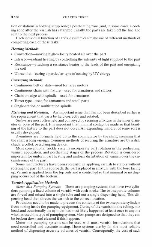
tion or stations; a holding setup zone; a postheating zone; and, in some cases, a cool-ing zone after the varnish has catalyzed. Finally, the parts are taken off the line andsent to the next process.
Each individual function of a trickle system can make use of different methods ofcompleting each of these tasks.
Heating Methods Convection—moving high-velocity heated air over the part Infrared—radiant heating by controlling the intensity of light supplied to the part Resistance—attaching a resistance heater to the leads of the part and energizing
the coil Ultraviolet—curing a particular type of coating by UV energy
Conveying Methods Continuous belt or slats—used for large motors Continuous chain with fixture—used for armatures and stators Chain on edge with spindle—used for armatures Turret type—used for armatures and small parts Single-station or multistation spindle
Fixturing and Rotation. An important issue that has not been described earlier isthe requirement that parts be held correctly and rotated.
Stators are most often held and conveyed by securing a fixture in the inner diam-eter or bore of the part. It is important that minimal contact be made so that bond-ing of the fixture to the part does not occur. An expanding mandrel of some sort isusually developed.
Armatures are normally held up to the commutator by the shaft, assuming thatthe shaft is long enough. Common methods of securing the armature are by a drillchuck, a collet, or a clamping device.
Most conventional trickle systems incorporate part rotation in the preheating,varnish application, and postheating stages of the process. Rotation is consideredimportant for uniform part heating and uniform distribution of varnish over the cir-cumference of the part.
Some manufacturers have been successful in applying varnish to stators withoutrotating the part. In this approach, the part is placed in a fixture with the bore facingup.Varnish is applied from the top only and is controlled so that minimal or no drip-ping occurs out of the bottom.
Varnish Application MethodsMeter-Mix Pumping Systems. These are pumping systems that have two cylin-
ders pumping a fixed volume of varnish with each stroke. The two separate volumesare forced and mixed into a single tube and out a single dispensing head. This dis-pensing head then directs the varnish to the correct location.
Provisions need to be made to prevent the contents of the two separate cylindersfrom mixing inside the pumping equipment. Curing of the varnish in the tubing, mixhead, and occasionally the cylinder has most likely happened at least once to anyonewho has used this type of pumping system. Most pumps are designed so that they canbe broken down and cleaned if this happens.
Meter-mix pumping systems can be used with most varnish formulations thatneed controlled and accurate mixing. These systems are by far the most reliablemethod of dispensing accurate volumes of varnish. Consequently, the cost of such
3.106 CHAPTER THREE

systems is higher than those used with other methods.A manufacturer is most likelyto use this type of pumping system when mixing has to occur just prior to dispensingthe varnish, such as with a quick-setting catalyzed varnish or when the processrequires strict control.
Peristaltic Pumps. Many older systems that used solvent-based varnishes onarmatures utilized this type of pumping system. Often there are multiple feeder linesthat continuously pump the varnish as the armatures travel past the tubing. Occa-sionally, a system indexes or cycles a number of parts past a fixed number of trickleheads. By doing this, the size of the equipment and system is often minimized.
Since the solvent-based varnishes cure by heat, and heat is generally kept awayfrom the trickle area, the resin that drips off is often recycled back to the main hold-ing tank, remixed, and reused.
With the new resins which catalyze after dispensing and heating, intermittent dis-pensing of a controlled volume of varnish on an individual part is becoming morecommon. Dispensing times and volumes based on the part size are normally deter-mined by testing. The actual varnish dispensing time is based on the volume of var-nish needed to properly coat the part and the rate at which the part can accept thevarnish with minimal dripping or runoff. Part temperature is critical with these newresins. If a part is too hot, the varnish often thins too much when it touches the part.On longer core stacks, the varnish sometimes sets up in the slots and prevents acomplete slot fill. If the temperature is too low, proper filling of the slots does notoccur and the final varnish film will appear uneven.
Maintenance of peristaltic pumping systems requires periodic replacement oftubing. Since varnish is not exposed directly to the pumping components, the pumpsremain relatively maintenance-free. Newer systems that dispense varnish to a singlepart at a number of precise locations require fewer pumps and pumping lines.
3.16.4 Process Times and Temperatures
Newer varnish formulations cure in minutes rather than hours. In the past, conven-tional varnishes required preheat temperatures of about 300°F (149°C) and baketemperatures of 350°F (177°C), whereas newer catalyzed varnishes have preheattemperatures in the range of 150 to 200°F (65 to 93°C) and bake temperatures justslightly higher. As a result of these lower cure temperatures, utility costs are alsoconsiderably reduced.
A generalized comparison of the energy cost for processing parts using a dip-and-bake resin and two available chemically cured trickle resins is shown in Tables 3.18 and 3.19. Identical 48-frame stator-coil assemblies were used in the
MECHANICS AND MANUFACTURING METHODS 3.107
TABLE 3.18 Energy Costs of Using Three Varnish Resins
Dip and bake Trickle, 100:3 Trickle, 100:1
Gas cost, Operating, Heat-up, Operating, Heat-up, Operating, Heat-up,City $/therm* $/h $ $/h $ $/h $
Milwaukee 0.49 1.45 2.52 0.60 0.46 0.34 0.19St. Louis 0.49 1.45 2.52 0.60 0.46 0.34 0.19Dallas 0.40 1.18 2.05 0.49 0.38 0.28 0.16Charlotte 0.55 1.63 2.82 0.68 0.52 0.39 0.22Nashville 0.33 0.98 1.70 0.41 0.31 0.23 0.13
* Therm = 100,000 BTU. All prices as of May 1995 with taxes included.
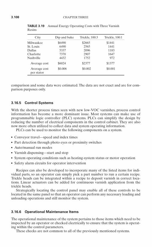
comparison and some data were estimated. The data are not exact and are for com-parison purposes only.
3.16.5 Control Systems
With the shorter process times seen with new low-VOC varnishes, process controlinformation has become a more dominant issue. Most systems can make use ofprogrammable logic controller (PLC) systems. PLCs can simplify the design byreducing the number of electrical components in the control cabinet. They are alsonow more often utilized to collect data and system operating information.
PLCs can be used to monitor the following components on a system.
Conveyor travel—speed and index times Part detection through photo eyes or proximity switches Auto/manual run modes Varnish dispensing—start and stop System operating conditions such as heating-system status or motor operation Safety alarm circuits for operator intervention
Recipes can also be developed to incorporate many of the listed items for indi-vidual parts, so an operator can simply pick a part number to run a certain recipe.Trickle heads can be integrated within a recipe to deposit varnish in correct loca-tions. Linear actuators can be added for continuous varnish application from thetrickle heads.
Strategically locating the control panel may enable all of these controls to belocated in the same panel so that an operator can perform any necessary loading andunloading operations and still monitor the system.
3.16.6 Operational Maintenance Items
The operational maintenance of the system pertains to those items which need to beinspected by an operator or checked electrically to ensure that the system is operat-ing within the control parameters.
These checks are not common to all of the previously mentioned systems.
3.108 CHAPTER THREE
TABLE 3.19 Annual Energy Operating Costs with Three VarnishResins
City Dip and bake Trickle, 100:3 Trickle, 100:1
Milwaukee $6490 $2665 $1441St. Louis 6490 2565 1441Dallas 5337 2096 1183Charlotte 7370 2907 1647Nashville 4432 1752 972
Average cost $6024 $2377 $1377
Average cost $0.006 $0.002 $0.001per stator

Varnish Holding Tanks Periodic cleaning for buildup of varnish Heating and cooling systems Circulation systems Holding and fill tanks Automatic or manual liquid levels
Trickle Equipment Tubing line replacement Pump-speed settings Trickle head location and setup Trickle head volume and flow control (closeups) Photo eye settings for automatic detection of parts
3.16.7 Preventive Maintenance
Care of conveyor systems Oven systems maintenance
Fan bearingsMotorsSheaves, belts, and drive unitsBurner flame safety and spark ignitors
Maintenance of pumps varnish-dispensing
3.16.8 Conclusion
It is evident that it takes years to learn all the tricks of the trade in operating andmaintaining the various varnish impregnation systems.
Fortunately, the systems are evolving into systems that are smaller and less com-plicated.A thorough evaluation of the size of a part, the quantity per hour being pro-duced, and the desired final quality needs to be conducted to determine what type ofsystem will best suit one’s needs.
3.17 ADHESIVES*
Designers and manufacturers will discover many benefits and opportunities associ-ated with adhesives and related materials in the assembly and fabrication of smallelectric motors. Adhesives can provide design advantages, improve overall productperformance, speed assembly time, and reduce costs of small motor manufacturingas indicated in Fig. 3.100.
MECHANICS AND MANUFACTURING METHODS 3.109
* Section contributed by John Cocco, Loctite Corporation.
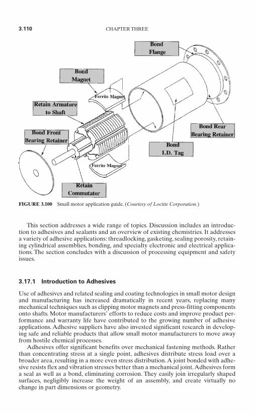
This section addresses a wide range of topics. Discussion includes an introduc-tion to adhesives and sealants and an overview of existing chemistries. It addressesa variety of adhesive applications: threadlocking, gasketing, sealing porosity, retain-ing cylindrical assemblies, bonding, and specialty electronic and electrical applica-tions. The section concludes with a discussion of processing equipment and safetyissues.
3.17.1 Introduction to Adhesives
Use of adhesives and related sealing and coating technologies in small motor designand manufacturing has increased dramatically in recent years, replacing manymechanical techniques such as clipping motor magnets and press-fitting componentsonto shafts. Motor manufacturers’ efforts to reduce costs and improve product per-formance and warranty life have contributed to the growing number of adhesiveapplications. Adhesive suppliers have also invested significant research in develop-ing safe and reliable products that allow small motor manufacturers to move awayfrom hostile chemical processes.
Adhesives offer significant benefits over mechanical fastening methods. Ratherthan concentrating stress at a single point, adhesives distribute stress load over abroader area, resulting in a more even stress distribution.A joint bonded with adhe-sive resists flex and vibration stresses better than a mechanical joint.Adhesives forma seal as well as a bond, eliminating corrosion. They easily join irregularly shapedsurfaces, negligibly increase the weight of an assembly, and create virtually nochange in part dimensions or geometry.
3.110 CHAPTER THREE
FIGURE 3.100 Small motor application guide. (Courtesy of Loctite Corporation.)
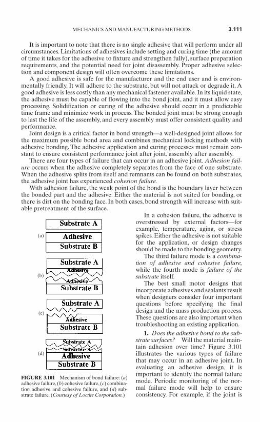
It is important to note that there is no single adhesive that will perform under allcircumstances. Limitations of adhesives include setting and curing time (the amountof time it takes for the adhesive to fixture and strengthen fully), surface preparationrequirements, and the potential need for joint disassembly. Proper adhesive selec-tion and component design will often overcome these limitations.
A good adhesive is safe for the manufacturer and the end user and is environ-mentally friendly. It will adhere to the substrate, but will not attack or degrade it. Agood adhesive is less costly than any mechanical fastener available. In its liquid state,the adhesive must be capable of flowing into the bond joint, and it must allow easyprocessing. Solidification or curing of the adhesive should occur in a predictabletime frame and minimize work in process. The bonded joint must be strong enoughto last the life of the assembly, and every assembly must offer consistent quality andperformance.
Joint design is a critical factor in bond strength—a well-designed joint allows forthe maximum possible bond area and combines mechanical locking methods withadhesive bonding. The adhesive application and curing processes must remain con-stant to ensure consistent performance joint after joint, assembly after assembly.
There are four types of failure that can occur in an adhesive joint. Adhesion fail-ure occurs when the adhesive completely separates from the face of one substrate.When the adhesive splits from itself and remnants can be found on both substrates,the adhesive joint has experienced cohesion failure.
With adhesion failure, the weak point of the bond is the boundary layer betweenthe bonded part and the adhesive. Either the material is not suited for bonding, orthere is dirt on the bonding face. In both cases, bond strength will increase with suit-able pretreatment of the surface.
In a cohesion failure, the adhesive isoverstressed by external factors—forexample, temperature, aging, or stressspikes. Either the adhesive is not suitablefor the application, or design changesshould be made to the bonding geometry.
The third failure mode is a combina-tion of adhesive and cohesive failure,while the fourth mode is failure of thesubstrate itself.
The best small motor designs thatincorporate adhesives and sealants resultwhen designers consider four importantquestions before specifying the finaldesign and the mass production process.These questions are also important whentroubleshooting an existing application.
1. Does the adhesive bond to the sub-strate surfaces? Will the material main-tain adhesion over time? Figure 3.101illustrates the various types of failurethat may occur in an adhesive joint. Inevaluating an adhesive design, it isimportant to identify the normal failuremode. Periodic monitoring of the nor-mal failure mode will help to ensureconsistency. For example, if the joint is
MECHANICS AND MANUFACTURING METHODS 3.111
FIGURE 3.101 Mechanism of bond failure: (a)adhesive failure, (b) cohesive failure, (c) combina-tion adhesive and cohesive failure, and (d) sub-strate failure. (Courtesy of Loctite Corporation.)
(a)
(b)
(c)
(d)
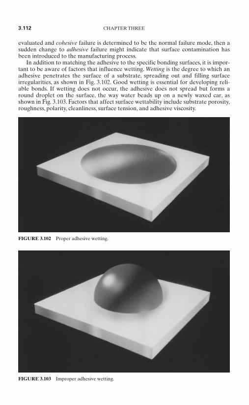
evaluated and cohesive failure is determined to be the normal failure mode, then asudden change to adhesive failure might indicate that surface contamination hasbeen introduced to the manufacturing process.
In addition to matching the adhesive to the specific bonding surfaces, it is impor-tant to be aware of factors that influence wetting. Wetting is the degree to which anadhesive penetrates the surface of a substrate, spreading out and filling surfaceirregularities, as shown in Fig. 3.102. Good wetting is essential for developing reli-able bonds. If wetting does not occur, the adhesive does not spread but forms around droplet on the surface, the way water beads up on a newly waxed car, asshown in Fig. 3.103. Factors that affect surface wettability include substrate porosity,roughness, polarity, cleanliness, surface tension, and adhesive viscosity.
3.112 CHAPTER THREE
FIGURE 3.102 Proper adhesive wetting.
FIGURE 3.103 Improper adhesive wetting.
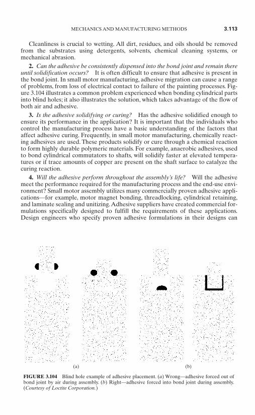
Cleanliness is crucial to wetting. All dirt, residues, and oils should be removedfrom the substrates using detergents, solvents, chemical cleaning systems, ormechanical abrasion.
2. Can the adhesive be consistently dispensed into the bond joint and remain thereuntil solidification occurs? It is often difficult to ensure that adhesive is present inthe bond joint. In small motor manufacturing, adhesive migration can cause a rangeof problems, from loss of electrical contact to failure of the painting processes. Fig-ure 3.104 illustrates a common problem experienced when bonding cylindrical partsinto blind holes; it also illustrates the solution, which takes advantage of the flow ofboth air and adhesive.
3. Is the adhesive solidifying or curing? Has the adhesive solidified enough toensure its performance in the application? It is important that the individuals whocontrol the manufacturing process have a basic understanding of the factors thataffect adhesive curing. Frequently, in small motor manufacturing, chemically react-ing adhesives are used. These products solidify or cure through a chemical reactionto form highly durable polymeric materials. For example, anaerobic adhesives, usedto bond cylindrical commutators to shafts, will solidify faster at elevated tempera-tures or if trace amounts of copper are present on the shaft surface to catalyze thecuring reaction.
4. Will the adhesive perform throughout the assembly’s life? Will the adhesivemeet the performance required for the manufacturing process and the end-use envi-ronment? Small motor assembly utilizes many commercially proven adhesive appli-cations—for example, motor magnet bonding, threadlocking, cylindrical retaining,and laminate sealing and unitizing.Adhesive suppliers have created commercial for-mulations specifically designed to fulfill the requirements of these applications.Design engineers who specify proven adhesive formulations in their designs can
MECHANICS AND MANUFACTURING METHODS 3.113
FIGURE 3.104 Blind hole example of adhesive placement. (a) Wrong—adhesive forced out ofbond joint by air during assembly. (b) Right—adhesive forced into bond joint during assembly.(Courtesy of Loctite Corporation.)
(a) (b)

minimize the risks associated with adhesive specification. However, since all designspossess unique requirements, both short- and long-term performance testing is sug-gested to ensure a design’s success.
To ensure a good, long-lasting bond, the properties of the adhesive must matchthe requirements of the manufacturing process and those of the end-user applica-tion. For example, if the adhesive used is not formulated for solvent resistance, andthe manufacturing or end-use environments subject the assembly to solvents, thebond will fail.
The manufacturer should consistently test devices for a series of performancefactors once the adhesive is fully cured and the assembled device is ready for enduse. A designer concerned about thermal performance, for example, must considerthe amount of time that the exposed part will be subjected to high temperatures. Fig-ure 3.105 graphically illustrates heat aging and hot strength. Hot strength tests areused to predict bond strength at a selected temperature. Heat aging tests are used todetermine long-term durability after exposure to elevated temperatures.
Most reputable adhesive suppliers will assist in developing testing programs, andin many cases, will provide testing services at no charge.
3.17.2 Joint Design Guidelines
Understanding the basic types of mechanical stresses will help in joint design. Typi-cal joint stresses are illustrated in Fig. 3.106.
Tensile stress. Occurs when the force on a joint is pulling the substrates awayfrom the bondline. Tensile stress tends to elongate the object.
3.114 CHAPTER THREE
FIGURE 3.105 Hot strength and heat aging are both impor-tant measures. (a) Hot strength—bond tested at temperature.(b) Heat aging—bond tested at room temperature. (Courtesyof Loctite Corporation.)
(a)
(b)
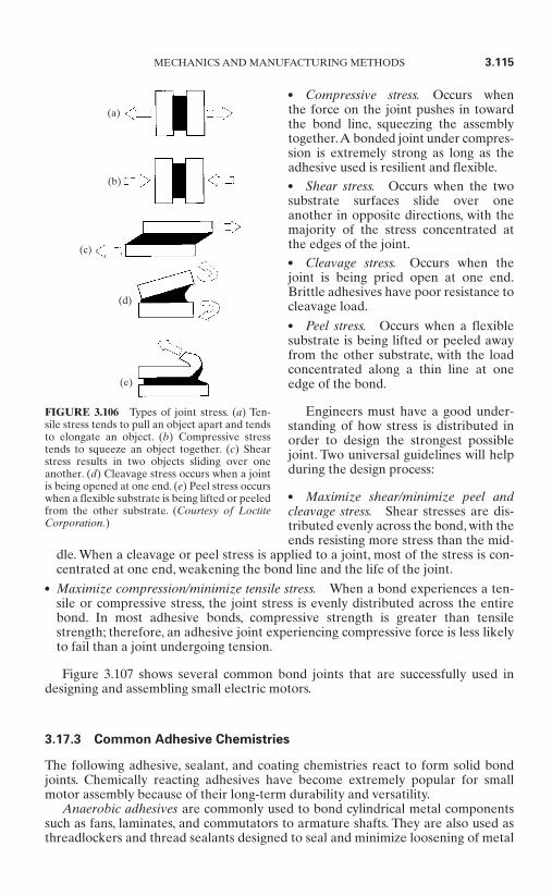
Compressive stress. Occurs whenthe force on the joint pushes in towardthe bond line, squeezing the assemblytogether.A bonded joint under compres-sion is extremely strong as long as theadhesive used is resilient and flexible. Shear stress. Occurs when the twosubstrate surfaces slide over oneanother in opposite directions, with themajority of the stress concentrated atthe edges of the joint. Cleavage stress. Occurs when thejoint is being pried open at one end.Brittle adhesives have poor resistance tocleavage load. Peel stress. Occurs when a flexiblesubstrate is being lifted or peeled awayfrom the other substrate, with the loadconcentrated along a thin line at oneedge of the bond.
Engineers must have a good under-standing of how stress is distributed inorder to design the strongest possiblejoint. Two universal guidelines will helpduring the design process:
Maximize shear/minimize peel andcleavage stress. Shear stresses are dis-tributed evenly across the bond, with theends resisting more stress than the mid-
dle. When a cleavage or peel stress is applied to a joint, most of the stress is con-centrated at one end, weakening the bond line and the life of the joint.
Maximize compression/minimize tensile stress. When a bond experiences a ten-sile or compressive stress, the joint stress is evenly distributed across the entirebond. In most adhesive bonds, compressive strength is greater than tensilestrength; therefore, an adhesive joint experiencing compressive force is less likelyto fail than a joint undergoing tension.
Figure 3.107 shows several common bond joints that are successfully used indesigning and assembling small electric motors.
3.17.3 Common Adhesive Chemistries
The following adhesive, sealant, and coating chemistries react to form solid bondjoints. Chemically reacting adhesives have become extremely popular for smallmotor assembly because of their long-term durability and versatility.
Anaerobic adhesives are commonly used to bond cylindrical metal componentssuch as fans, laminates, and commutators to armature shafts. They are also used asthreadlockers and thread sealants designed to seal and minimize loosening of metal
MECHANICS AND MANUFACTURING METHODS 3.115
FIGURE 3.106 Types of joint stress. (a) Ten-sile stress tends to pull an object apart and tendsto elongate an object. (b) Compressive stresstends to squeeze an object together. (c) Shearstress results in two objects sliding over oneanother. (d) Cleavage stress occurs when a jointis being opened at one end. (e) Peel stress occurswhen a flexible substrate is being lifted or peeledfrom the other substrate. (Courtesy of LoctiteCorporation.)
(a)
(b)
(c)
(d)
(e)
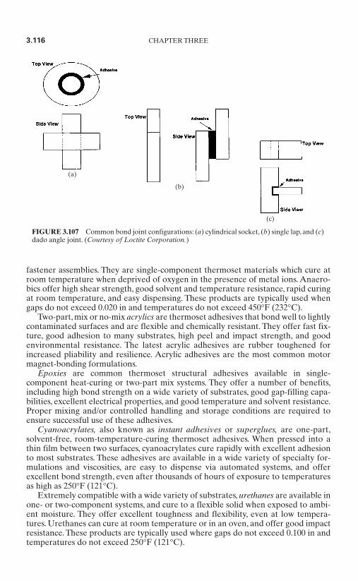
fastener assemblies. They are single-component thermoset materials which cure atroom temperature when deprived of oxygen in the presence of metal ions. Anaero-bics offer high shear strength, good solvent and temperature resistance, rapid curingat room temperature, and easy dispensing. These products are typically used whengaps do not exceed 0.020 in and temperatures do not exceed 450°F (232°C).
Two-part, mix or no-mix acrylics are thermoset adhesives that bond well to lightlycontaminated surfaces and are flexible and chemically resistant. They offer fast fix-ture, good adhesion to many substrates, high peel and impact strength, and goodenvironmental resistance. The latest acrylic adhesives are rubber toughened forincreased pliability and resilience. Acrylic adhesives are the most common motormagnet-bonding formulations.
Epoxies are common thermoset structural adhesives available in single-component heat-curing or two-part mix systems. They offer a number of benefits,including high bond strength on a wide variety of substrates, good gap-filling capa-bilities, excellent electrical properties, and good temperature and solvent resistance.Proper mixing and/or controlled handling and storage conditions are required toensure successful use of these adhesives.
Cyanoacrylates, also known as instant adhesives or superglues, are one-part,solvent-free, room-temperature-curing thermoset adhesives. When pressed into athin film between two surfaces, cyanoacrylates cure rapidly with excellent adhesionto most substrates. These adhesives are available in a wide variety of specialty for-mulations and viscosities, are easy to dispense via automated systems, and offerexcellent bond strength, even after thousands of hours of exposure to temperaturesas high as 250°F (121°C).
Extremely compatible with a wide variety of substrates, urethanes are available inone- or two-component systems, and cure to a flexible solid when exposed to ambi-ent moisture. They offer excellent toughness and flexibility, even at low tempera-tures. Urethanes can cure at room temperature or in an oven, and offer good impactresistance. These products are typically used where gaps do not exceed 0.100 in andtemperatures do not exceed 250°F (121°C).
3.116 CHAPTER THREE
FIGURE 3.107 Common bond joint configurations: (a) cylindrical socket, (b) single lap, and (c)dado angle joint. (Courtesy of Loctite Corporation.)
(a)
(c)
(b)
Silicones are rubberlike polymers which cure at room temperature. They exhibitexcellent resistance to high temperatures and moisture and are well suited for out-door weathering applications as sealants and caulking compounds. Silicones havesuperior chemical and electrical resistance, and good gap-filling capabilities, andthey are excellent for bonding glass to most other substrates. However, their low ten-sile strength limits their usefulness in carrying structural loads. It is important tomaintain controlled curing conditions (e.g., ambient temperature and humidity) toensure optimal results with silicones.
Many of these technologies can be adapted to employ UV or visible light to ini-tiate curing. UV- and visible-light-curing adhesives contain photoinitiators whichabsorb light energy to begin the cure.This technology is excellent for manufacturingapplications, as it allows the user to take as much time as necessary to position parts.The capability to cure on demand speeds processing and reduces total productioncosts. Upon exposure to a light source, the adhesive can be fully cured in less than aminute.
UV- and visible-light-curing formulations are becoming increasingly popular insmall motor manufacturing for a number of reasons:
They contain no solvents and do not require heat curing. They eliminate the need for holding racks and ovens. They allow flexible work-cell manufacturing configurations. They cure quickly and with precision control.
Light-curing products are currently replacing heat-curing and two-part epoxies, var-nishes, trickle coatings, and many other assembly systems commonly found in smallmotor manufacture.
3.17.4 Adhesives in Small Electric Motor Assembly
Threadlocking. Mechanical fasteners and adhesives can work together to form astronger bond than either method alone can provide. Design engineers who want toimprove the safety and quality of an assembly will use a mechanical fastener in tandemwith a threadlocking adhesive.The anaerobic threadlocker guarantees that the assem-bly will not fail or loosen and that corrosion will not reduce the life of the fastener.
Since threadlocking agents prevent loosening and movement and act as sealants,they can be used on small motor assemblies for tamperproofing, mounting bolts,locking assembly screws, bolting flanges, and setting adjustment screws. Threadlock-ers also offer excellent performance when used on severe-duty fasteners since theyseal the bond joint and prevent corrosion.They offer excellent performance in high-temperature and high-vibration areas.
Threaded assemblies fail for two reasons. One cause is tension relaxation. Tem-perature changes, for example, cause bolts and substrate materials to expand andcontract, reducing bolt tension and lowering the clamping force.The second cause ofthreaded assembly failure is self-loosening caused by sliding or vibration betweencontact surfaces.
Threadlocking adhesives prevent bolts from loosening by completely fillingmicroscopic gaps between interfacing threads. In fact, threadlocking agents maintainclamp load better than lock washers in high-vibration environments. Liquid anaero-bic threadlockers cure to a tough solid when they contact metal ions in the absenceof air. When selecting a threadlocking adhesive, designers should consider end-use
MECHANICS AND MANUFACTURING METHODS 3.117
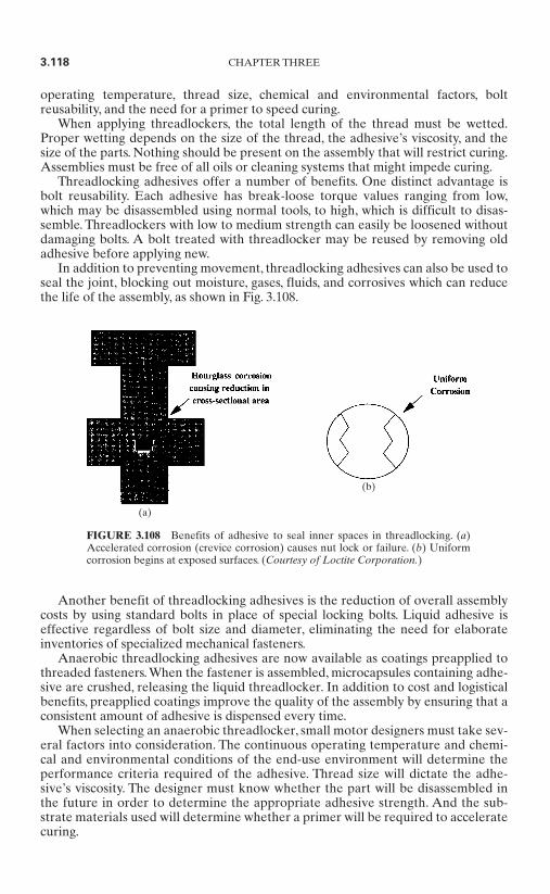
operating temperature, thread size, chemical and environmental factors, boltreusability, and the need for a primer to speed curing.
When applying threadlockers, the total length of the thread must be wetted.Proper wetting depends on the size of the thread, the adhesive’s viscosity, and thesize of the parts. Nothing should be present on the assembly that will restrict curing.Assemblies must be free of all oils or cleaning systems that might impede curing.
Threadlocking adhesives offer a number of benefits. One distinct advantage isbolt reusability. Each adhesive has break-loose torque values ranging from low,which may be disassembled using normal tools, to high, which is difficult to disas-semble. Threadlockers with low to medium strength can easily be loosened withoutdamaging bolts. A bolt treated with threadlocker may be reused by removing oldadhesive before applying new.
In addition to preventing movement, threadlocking adhesives can also be used toseal the joint, blocking out moisture, gases, fluids, and corrosives which can reducethe life of the assembly, as shown in Fig. 3.108.
Another benefit of threadlocking adhesives is the reduction of overall assemblycosts by using standard bolts in place of special locking bolts. Liquid adhesive iseffective regardless of bolt size and diameter, eliminating the need for elaborateinventories of specialized mechanical fasteners.
Anaerobic threadlocking adhesives are now available as coatings preapplied tothreaded fasteners. When the fastener is assembled, microcapsules containing adhe-sive are crushed, releasing the liquid threadlocker. In addition to cost and logisticalbenefits, preapplied coatings improve the quality of the assembly by ensuring that aconsistent amount of adhesive is dispensed every time.
When selecting an anaerobic threadlocker, small motor designers must take sev-eral factors into consideration. The continuous operating temperature and chemi-cal and environmental conditions of the end-use environment will determine theperformance criteria required of the adhesive. Thread size will dictate the adhe-sive’s viscosity. The designer must know whether the part will be disassembled inthe future in order to determine the appropriate adhesive strength. And the sub-strate materials used will determine whether a primer will be required to acceleratecuring.
3.118 CHAPTER THREE
FIGURE 3.108 Benefits of adhesive to seal inner spaces in threadlocking. (a)Accelerated corrosion (crevice corrosion) causes nut lock or failure. (b) Uniformcorrosion begins at exposed surfaces. (Courtesy of Loctite Corporation.)
(a)
(b)
Sealing Pores and Laminations. Advanced product designs and new manufactur-ing techniques require modern methods for filling and sealing the voids, or micro-porosity, in substrate surfaces such as metal castings, powdered-metal parts,electronic components, plastic composites, weldments, and other porous materials.Pore sealants, also called impregnation resins, are used in a variety of applications,including sealing pores in metal housings and other structural components, unitizingcommutators and other porous subcomponent parts, sealing electrical connectors,sealing magnets and other nonstructural components, and unitizing windings andlaminate stacks.
Today, designers are creating new lightweight, thin-walled die castings for use inapplications containing high-pressure fluids. These castings would not be possiblewithout the sophisticated new vacuum-impregnation systems and sealants. Design-ers seeking to decrease the weight or cost of assemblies rely upon impregnation,which enables them to design thinner-walled die castings or to switch to lower-costmethods, such as powdered metal. Modern resin impregnation systems are so wellaccepted, effective, and economical that traditional leak testing of heavily machinedcastings has been phased out in favor of impregnation of parts.
There are two types of porosity. Macroporosity requires remelting because thegaps affect structural integrity. Microporosity does not affect structural strength andis the natural result of two physical phenomena which occur as molten metal solidi-fies—crystal formation and shrinkage, and gas absorption. Visible surface defectsare usually not improved by pore sealing as the sealant washes out of the surfacedefects during processing, leaving them unchanged. Porosity that occurs on a micro-scopic scale can be readily sealed through impregnation. Even if a pore is large scalewithin the casting, it can be sealed if the surface opening is not large.
The most common reason for impregnation of castings is to enable parts to retainfluids under pressure. Properly impregnated, components such as hydraulic pumpand motor parts are permanently sealed and can hold pressures up to the burststrength of the casting. Castings are also impregnated in preparation for metal-finishing operations such as painting or plating. In some instances, it may be desir-able to seal pores in a casting so that corrosive fluids cannot enter. This is done toprevent corrosion that may originate within the porosity.
Castings should be fully machined, cleaned, and dried before impregnation, andshould be at room temperature. Only after all machining is completed can theimpregnation sealant reach into all areas that need to be sealed. The pores of clean,dry parts will not be blocked with foreign materials that might prevent thoroughpenetration of the impregnation sealant.
Powdered-metal parts should be impregnated after sintering but before any sec-ondary operations.The pores are normally completely open at that point and can befilled by the impregnation sealant.
Plating, painting, or other finishing operations for either castings or powdered-metal parts should be done after the impregnation is complete and the sealant hasbeen allowed to fully cure. The cured sealant in the impregnated parts will not beaffected by the various cleaning and etching steps, even when strongly acidic solu-tions are used.
The unique self-curing capability of anaerobic sealants, along with the ability toregulate the rate of cure, has made anerobics the most reliable family of materialsfor sealing the porosity of metallic and nonmetallic parts.The ability to cure withoutheating the parts, combined with the use of an activator rinse to speed curing, givesthe anaerobic sealants much greater capability in sealing a wide range of pore sizes,especially larger pores. Bleedout will not happen with anaerobic sealants, so partfouling does not occur and sealing performance is consistently high.
MECHANICS AND MANUFACTURING METHODS 3.119
Certain formulations of cured anaerobic sealants are suitable for continuous ser-vice up to 392°F (200°C). Brief exposure to higher temperatures, as might occur inpaint ovens, will not normally cause problems. These sealants can be used success-fully in such high-temperature environments as automotive engine blocks, cylinderheads, and coolant pumps. The cured sealant is a thermoset plastic which will notmelt, liquefy, or run out of parts at elevated temperatures. If operated beyondacceptable temperatures, the cured sealant will slowly lose weight and turn to ash.
Impregnation sealants are tested by the manufacturer for chemical resistance todetermine their suitability to environments exposed to fuels, lubricants, coolants,cleaners, and other chemicals that may be encountered in automotive, aerospace,and general industrial environments.
Gasketing (Flange Sealing). Gaskets (flange sealants) prevent leakage of liquidsor gases by forming impervious barriers between mating flanges. In small motorapplications, flange sealants are used for gasketing fluid- and air-tight components,sealing crimped components, sealing flange couplings for improved power transmis-sion, and ensuring the performance of hermetically sealed components.
There are three types of flange gaskets: conventional compression gaskets ofcork, paper, rubber, metal, and other asbestos-free materials; cured-in-place liquidcompression gaskets cured in seconds with UV light prior to assembly; and formed-in-place liquid gaskets cured after the parts are assembled.All three types of gasketsmust create and maintain seals, remain impervious to fluid flow, and be compatiblewith the machinery.
Liquid formed-in-place (FIP) gasketing materials are used to dress conventionalrubber, paper, or cork gasketing materials, and can often completely replace cut gas-kets. These liquid anaerobic gasket dressings fill surface imperfections in the matingflanges and extend the life of the gasket. When parts are assembled, the flangesealant flows into voids, gaps, and scratch marks, forming a durable seal after curing.Formed-in-place gaskets offer a number of advantages over precut compression gas-kets, including improved reliability, reduced costs, and easier application and service.Two common types of FIP materials are room-temperature-vulcanizing (RTV) sili-cones and anaerobic compounds.
Anaerobic FIP materials are generally used on rigid joints made of cast alu-minum or iron, such as pumps, engines, and transmissions. Anaerobic gaskets offerseveral benefits over traditional sealing systems.They will not relax, so retorquing isnever necessary. These materials allow metal-to-metal contact, and therefore do notrequire shimming. Anaerobics will not begin to cure before flanges are mated, andany excess material which squeezes out of the flange faces will not cure and can beeasily wiped away. These high-shear-strength materials demonstrate excellent sol-vent resistance and chemical compatibility, and eliminate the need for large inven-tories of precut gaskets.
RTV silicones cure by reacting with atmospheric moisture and are typically usedon high-movement joints made of stamped steel or molded plastic. RTV silicones areapplied as beads to the flange area of a component, and flow over the flange to form agasket that completely fills voids, scratches, and other surface imperfections.They pro-vide a small amount of squeeze-out on both the inside and outside of the joint, form-ing a fillet around the flange which acts as a secondary seal. FIP silicones are capableof filling large gaps, flex easily in response to the movement of the flange, adhere wellto many surfaces, and withstand a wide range of temperatures. As with anaerobicmaterials, silicones eliminate the need for large and costly gasket inventories.
Silicone cured-in-place (CIP) gasketing involves positioning a compression gas-ket as a permanent part of one flange surface. The gasket is created by a tracing
3.120 CHAPTER THREE
machine which applies precise beads of silicone to the flange surfaces.The beads arecured and bonded to the component flange in 30 s with UV light, or in 7 to 14 dayswith slow moisture curing. Sealing is achieved through compression of the cured gas-ket during assembly of the flange joint. CIP compression gaskets offer many advan-tages over die-cut rubber, die-cut foam rubber, or molded gaskets. Equipmentmanufactured with CIP-sealed access ports is easy to produce and service. CIP gas-kets reduce labor costs, improve product quality, reduce gasket inventories, andallow flexibility in the manufacturing process.
Retaining Cylindrical Assemblies. The term retaining compounds describes adhe-sives used in cylindrical assemblies joined by inserting one part into another. A typ-ical example is a bearing mounted in an electric motor housing. Retainingcompounds enable buyers of new bearings to salvage worn housings.
Incorporating retaining compounds into the assembly of small electric motors pro-vides a number of performance benefits. Retaining compounds can augment, improve,or replace normal press fits and can increase the strength of heavy press fits.They alsoeliminate distortion when installing drill bushings. Retaining creates an essential sealwhich eliminates fretting corrosion and seizure. Finally, retaining compounds help toreduce stress in parts and enhance the combined performance of substrate materials.
Retaining compounds are used in a variety of small motor applications: mount-ing bearings in housings or on shafts; attaching pulleys, cams, fans, and gears; replac-ing or augmenting interference fits, keyways, and splines; retaining commutators andmounting flanges; and assembling armatures. Retaining compounds work extremelywell on cylindrical components made of dissimilar materials, as well as on parts thatmust be protected from corrosion and backlash.
Retaining compounds are primarily anaerobic materials, used to bond metal tometal or metal to a nonmetallic substrate. However, for nonmetallic substrates suchas plastics, cyanoacrylate adhesives can be used.
Two key formulation variables exist for anaerobic retaining compounds. The vis-cosity of the adhesive determines its ability to fill gaps in the assembly—the higherthe viscosity of the material, the greater its ability to fill gaps. Like threadlockers,anaerobic retaining compounds are formulated in different strengths—from low,which may be easily disassembled, to high, which is difficult to disassemble. Anassembly treated with the appropriate-strength anaerobic retaining compound maybe disassembled and reused.
As with all adhesives, it is extremely important that substrates be thoroughlycleaned before retaining compounds are applied. Contamination will greatly inhibitcuring, especially on metallic substrates.
Retaining compounds are crucial in two types of cylindrical assemblies. Inbonded slip-fit assemblies, the shaft is inserted into the hub with no force required.Cured adhesive located between the shaft and the hub transmits the load or torque.In bonded interference-fit assemblies, friction and the adhesive combine to transmitthe load or torque. There are two types of interference fit assemblies—bondedshrink fits, where the hub is heated to allow insertion of the shaft, and bonded pressfits, where axial force allows insertion of the shaft
In selecting an appropriate retaining compound, designers should consider the typeof assembly being bonded, the thermal expansion of the individual substrates, theradial clearance of the bonded slip-fit assemblies, the required shear strength and easeof disassembly, and the continuous operating temperature of the end-use environment.
Bonding. A number of adhesive technologies are commonly used for bonding avariety of substrate surfaces to one another. Common surface-bonding opportuni-
MECHANICS AND MANUFACTURING METHODS 3.121

ties for small motor assembly include flat-face bonding, plastic and sheet-metalbonding, motor magnet bonding, affixing nameplates or identification tags, attachingthe housing to the base, bonding armature segments, and bonding the cooling fins tothe heat sink.
When bonding assemblies with large gaps, high-viscosity adhesives can act asfillers, occupying space between substrate surfaces. However, there is an inverserelationship between the size of the gap and the overall performance of the adhe-sive. Large gaps reduce the adhesive’s bond strength and durability and increase thefixture time required, diminishing the adhesive’s effectiveness.
Magnet Bonding. Acrylic adhesives are now used extensively to bond magnet segments in motor manufacturing. Millions of motors are operating successfully indemanding environments using only adhesive systems to reliably secure their magnets.
Magnet bonding has evolved significantly over the past decade. Ten to fifteenyears ago, it was common to use spring steel clips to fix magnet segments into posi-tion. In addition to the relatively high cost of materials, magnet clipping was difficultto automate and required relatively complex parts-handling systems and insertion.In addition, clips could loosen or shift, allowed corrosion to occur between the mag-net and the motor assembly, and did nothing to prevent noise and vibration.
As cost and performance became increasingly important, many motor manufac-turers who were skeptical of adhesives’ bonding performance began to use epoxyadhesives to prevent corrosion and reduce noise, but still augmented the bond usingclips. Adhesive suppliers began to develop formulations specifically for magnet-bonding applications. Specialty acrylic adhesives that were tough and environmen-tally resistant were introduced to bond magnets without clips.
Adhesives proved successful in motor magnet bonding because they weredesigned to process quickly and bond reliably in less-than-ideal industrial environ-ments. In addition, adhesive bonds last through the severest environments that amotor may encounter.
Factors relating to the magnet and the housing play a critical role in successfulmagnet bonding. Magnets must be dust-free and be formed or machined to ensurethat gaps between the magnet and the housing remain small. Most magnet-bondingadhesives solidify faster and are stronger when gaps are less than .010 in. For curvedmagnet segments, some motor manufacturers have moved from single-radius seg-ments to the tri-arc configuration seen in Fig. 3.109. This design helps to reducemovement of the magnet in the fixture, and can help reduce the gap due to tolerancedifferences between the housing and the magnet. Examination of the tri-arc bondjoints shows that the adhesive fixtures or solidifies quickly at the two points of con-tact on the magnet surface.
The surface and shape of the housing can be crucial to the success of the bondingdesign.The surfaces of housings are often fabricated so that they resist corrosion andcan be painted. Conversion coating processes such as chromating, phosphating, gal-vanizing, and anodizing are used to fabricate housing surfaces. In most cases, pre-paint coatings such as zinc phosphate or chromic acid anodizing are the best foradhesive bonds. Coating processes that leave weak surface layers can be problem-atic. Such processes include galvanizing or yellow zinc dichromating. Some adhesivemanufacturers have developed primers that repair weak coating surfaces.
The method used to fabricate the housing will often affect its ultimate dimen-sional tolerance. Tighter control of housing dimensions can be used to ensure smallbondline gaps. Drawn or extruded housings are typically the most stable from adimensional standpoint. Magnet bonded housings are commonly roll-formed hous-ings, which are more difficult to control dimensionally. When rolled housings are
3.122 CHAPTER THREE
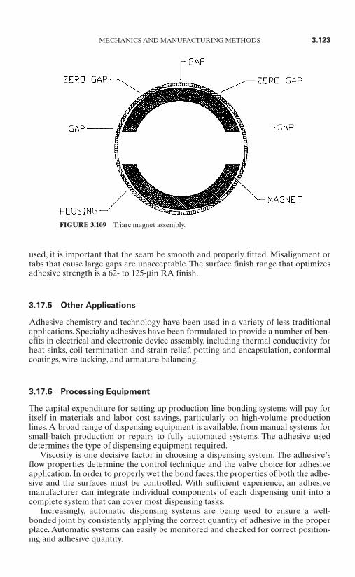
used, it is important that the seam be smooth and properly fitted. Misalignment ortabs that cause large gaps are unacceptable. The surface finish range that optimizesadhesive strength is a 62- to 125-µin RA finish.
3.17.5 Other Applications
Adhesive chemistry and technology have been used in a variety of less traditionalapplications. Specialty adhesives have been formulated to provide a number of ben-efits in electrical and electronic device assembly, including thermal conductivity forheat sinks, coil termination and strain relief, potting and encapsulation, conformalcoatings, wire tacking, and armature balancing.
3.17.6 Processing Equipment
The capital expenditure for setting up production-line bonding systems will pay foritself in materials and labor cost savings, particularly on high-volume productionlines. A broad range of dispensing equipment is available, from manual systems forsmall-batch production or repairs to fully automated systems. The adhesive useddetermines the type of dispensing equipment required.
Viscosity is one decisive factor in choosing a dispensing system. The adhesive’sflow properties determine the control technique and the valve choice for adhesiveapplication. In order to properly wet the bond faces, the properties of both the adhe-sive and the surfaces must be controlled. With sufficient experience, an adhesivemanufacturer can integrate individual components of each dispensing unit into acomplete system that can cover most dispensing tasks.
Increasingly, automatic dispensing systems are being used to ensure a well-bonded joint by consistently applying the correct quantity of adhesive in the properplace. Automatic systems can easily be monitored and checked for correct position-ing and adhesive quantity.
MECHANICS AND MANUFACTURING METHODS 3.123
FIGURE 3.109 Triarc magnet assembly.

3.17.7 Safety
Employee safety and environmental friendliness are two issues of concern through-out the industrialized world. Manufacturers are striving to develop production pro-cesses which ensure compliance with the stricter safety and environmental standardsin place today. The trend toward safety has created both challenges and opportuni-ties for the adhesives, sealants, and coatings industry.
Although most adhesives have evolved to meet stringent safety requirements,improper handling and process design will yield unnecessary problems and expenses.
It is possible to achieve a safe and trouble-free adhesive process if safe handlingand use issues are attended to during the process design stage. Implementing anappropriate safety and ventilation strategy can make the difference between successand failure.
Extensive information concerning the safe handling of chemicals in the workplaceexists, but it is scattered and difficult to gather, filter, and apply to specific operations.Your adhesive supplier should be able to provide guidance on material safety; safeshipping and storage of unopened containers; minimizing and monitoring exposureto potentially dangerous materials; and waste collection, storage, and disposal.
3.18 MAGNETIZERS, MAGNETIZING FIXTURES,AND TEST EQUIPMENT*
This section is intended to provide practical guidelines for analyzing and selectingequipment for magnetizing, demagnetizing, and measurement systems.An overviewof the information required to analyze a typical application and some of the reason-ing for each item is provided. A checklist of required information and descriptionsof various magnetizing and calibration systems follows. In many cases, several dif-ferent magnetizing systems could be recommended for any given application. Themost important aspect of the analysis is developing a complete picture of therequirements. This can happen only with an ongoing dialog between the productdesign and manufacturing engineers and the equipment supplier.
In the early product development stage, magnet suppliers can assist project engi-neers in the selection of the appropriate magnet material for any given project.Withthe extreme range of magnet materials available today (see Table 3.20), a closeworking relationship with magnet producers and equipment suppliers is increasinglyimportant.
Magnetizer equipment manufacturers can assist you in selecting the right equip-ment after the magnet material has been selected.
3.18.1 Checklist
The following items should be discussed by the project engineers and the productsuppliers:
Magnet material Grade Characteristics
3.124 CHAPTER THREE
* Section contributed by Roger O. LaValley, Magnetic Instrumentation.
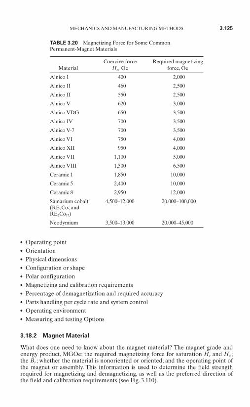
Operating point Orientation Physical dimensions Configuration or shape Polar configuration Magnetizing and calibration requirements Percentage of demagnetization and required accuracy Parts handling per cycle rate and system control Operating environment Measuring and testing Options
3.18.2 Magnet Material
What does one need to know about the magnet material? The magnet grade andenergy product, MGOe; the required magnetizing force for saturation Hc and Hci;the Br ; whether the material is nonoriented or oriented; and the operating point ofthe magnet or assembly. This information is used to determine the field strengthrequired for magnetizing and demagnetizing, as well as the preferred direction ofthe field and calibration requirements (see Fig. 3.110).
MECHANICS AND MANUFACTURING METHODS 3.125
TABLE 3.20 Magnetizing Force for Some Common Permanent-Magnet Materials
Coercive force Required magnetizingMaterial Hc , Oe force, Oe
Alnico I 400 2,000
Alnico II 460 2,500
Alnico II 550 2,500
Alnico V 620 3,000
Alnico VDG 650 3,500
Alnico IV 700 3,500
Alnico V-7 700 3,500
Alnico VI 750 4,000
Alnico XII 950 4,000
Alnico VII 1,100 5,000
Alnico VIII 1,500 6,500
Ceramic 1 1,850 10,000
Ceramic 5 2,400 10,000
Ceramic 8 2,950 12,000
Samarium cobalt 4,500–12,000 20,000–100,000(RE2Co5 and RE2Co17)
Neodymium 3,500–13,000 20,000–45,000
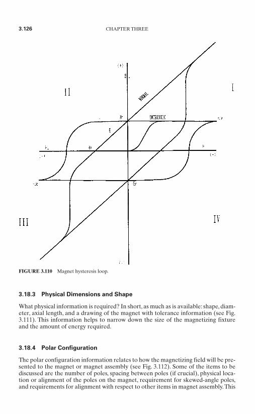
3.18.3 Physical Dimensions and Shape
What physical information is required? In short, as much as is available: shape, diam-eter, axial length, and a drawing of the magnet with tolerance information (see Fig.3.111). This information helps to narrow down the size of the magnetizing fixtureand the amount of energy required.
3.18.4 Polar Configuration
The polar configuration information relates to how the magnetizing field will be pre-sented to the magnet or magnet assembly (see Fig. 3.112). Some of the items to bediscussed are the number of poles, spacing between poles (if crucial), physical loca-tion or alignment of the poles on the magnet, requirement for skewed-angle poles,and requirements for alignment with respect to other items in magnet assembly.This
3.126 CHAPTER THREE
FIGURE 3.110 Magnet hysteresis loop.
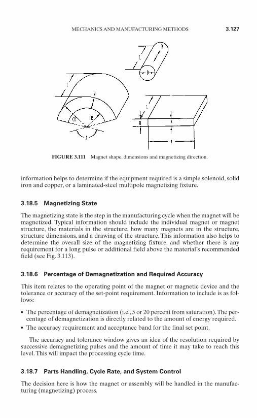
information helps to determine if the equipment required is a simple solenoid, solidiron and copper, or a laminated-steel multipole magnetizing fixture.
3.18.5 Magnetizing State
The magnetizing state is the step in the manufacturing cycle when the magnet will bemagnetized. Typical information should include the individual magnet or magnetstructure, the materials in the structure, how many magnets are in the structure,structure dimensions, and a drawing of the structure. This information also helps todetermine the overall size of the magnetizing fixture, and whether there is anyrequirement for a long pulse or additional field above the material’s recommendedfield (see Fig. 3.113).
3.18.6 Percentage of Demagnetization and Required Accuracy
This item relates to the operating point of the magnet or magnetic device and thetolerance or accuracy of the set-point requirement. Information to include is as fol-lows:
The percentage of demagnetization (i.e., 5 or 20 percent from saturation).The per-centage of demagnetization is directly related to the amount of energy required.
The accuracy requirement and acceptance band for the final set point.
The accuracy and tolerance window gives an idea of the resolution required bysuccessive demagnetizing pulses and the amount of time it may take to reach thislevel. This will impact the processing cycle time.
3.18.7 Parts Handling, Cycle Rate, and System Control
The decision here is how the magnet or assembly will be handled in the manufac-turing (magnetizing) process.
MECHANICS AND MANUFACTURING METHODS 3.127
FIGURE 3.111 Magnet shape, dimensions and magnetizing direction.
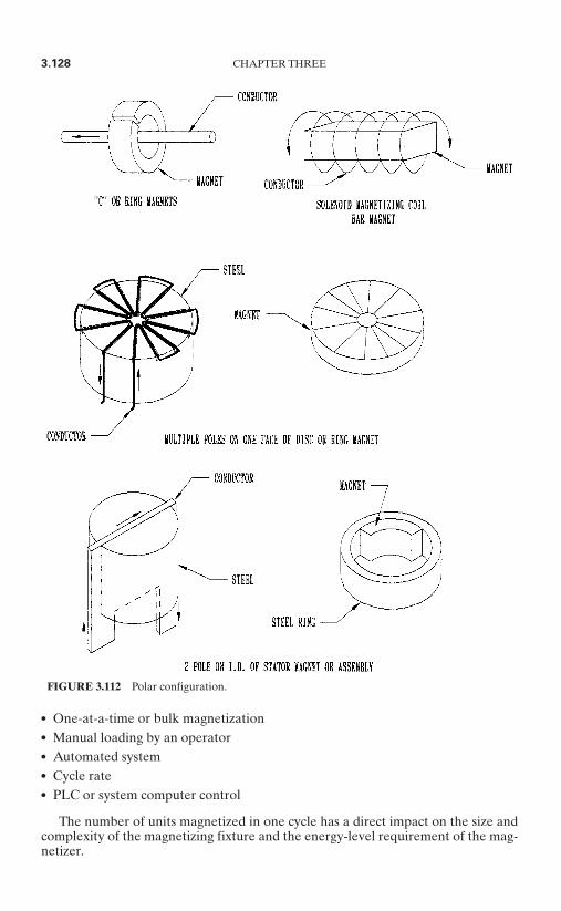
One-at-a-time or bulk magnetization Manual loading by an operator Automated system Cycle rate PLC or system computer control
The number of units magnetized in one cycle has a direct impact on the size andcomplexity of the magnetizing fixture and the energy-level requirement of the mag-netizer.
3.128 CHAPTER THREE
FIGURE 3.112 Polar configuration.

The cycle rate can have an impact on the decision to offer a dc electromagnet,capacitive discharge, or half-cycle magnetizer. It may also impact the system coolingrequirements and fixture design. The cycle rate is one of the key factors in decidingbetween a half-cycle or capacitive-discharge system.
If PLC or computer control is desired, one needs to understand what externalcontrols may be required to interface with automation equipment or system con-trollers and software.
3.18.8 Operating Environment
The operating environment considerations are as follows:
Whether the equipment will be used in a laboratory, clean room, or productionenvironment
Any unusual temperature or humidity considerations Available input power
A laboratory magnetizer normally requires much slower cycle rates, potentiallyless energy, and less automation. In many cases, a laboratory magnetizer is not easilytransferred into production.
Clean room requirements can be very restrictive and need to be identified earlyin the design cycle.
The selection of system enclosures to accommodate temperature and humidityextremes may be a consideration.
3.18.9 Measuring and Testing Options
There are many different ways to assure the quality of the magnetizing process, mag-net material, or magnet assembly. The following options provide various levels ofcontrol over the manufacturing and magnetizing process.
MECHANICS AND MANUFACTURING METHODS 3.129
FIGURE 3.113 Magnet magnetized in an assembly.
A current monitor with a comparator circuit to measure and compare the magne-tizing current at acceptable levels
Gaussmeters with comparator circuits to measure either the magnetizing pulse orthe residual flux density in the magnet
Fluxmeters with comparator circuits in conjunction with search coils, embedded inmagnetizing fixtures, to measure the total flux density of the magnet or assembly
Temperature monitors to measure temperature rise in magnetizing fixtures and tohalt the magnetizing process if the temperature rise goes above a safe level
A PLC system controller or computer in conjunction with the preceding equip-ment to control the operation and store statistical information
Individual manufacturing and quality assurance philosophies typically drive thedecision to add these various testing options.
3.18.10 Magnetizer Types
Magnetizers may be generalized into four categories: the permanent-magnet mag-netizer, the dc magnetizer or electromagnet, the half-cycle impulse magnetizer, andthe stored-energy or capacitive-discharge magnetizer.
Permanent-Magnet Magnetizer. The older-style permanent-magnet magnetizersconsisted of a large U-shaped permanent magnet (usually alnico V) havingadjustable pole pieces.The maximum air gap length is usually about 1.25 in.With thegap adjusted for a length of 1 in, a field of about 3000 Oe is obtainable.
The advent of high-energy permanent-magnet material has enhanced the devel-opment of permanent-magnet magnetizers.
DC Magnetizer (Electromagnet). The dc magnetizer utilizes one or two coils ofwire wound on an iron frame having a C-shaped configuration. Adjustable polepieces allow air gaps of various lengths to be used. Direct current is applied to thecoils, and the resultant electromagnetic force produces a magnetic field in the air gap.
DC magnetizers are limited to charging straight or slightly curved magnets. ManyC-shaped and U-shaped configurations cannot be fully saturated on this type ofmagnetizer; since the main magnetizing path is straight, the leakage field around thepole pieces is curved.
The duty cycle of the dc magnetizer is usually rather short, due to the largeamount of heat generated by the current passing through the coils.
The dc magnetizer is useful primarily where fields having a straight-line charac-teristic are required. The relatively long time base of the magnetizing field (2 s orlonger) is important where magnet assemblies having high eddy current losses are tobe charged. An example of this would be large magnets contained in a cast-aluminum housing.
Half-Cycle Magnetizer. The advantage of a half-cycle magnetizer, illustrated inFig. 3.114, is its ability to generate pulses at a very fast rate.The half-cycle magnetizeroperates by picking off one-half cycle from the power line. It will pass a part of ahalf-cycle with 1, 2, or 3 cycles from a 110- to 600-Vac 50- or 60-Hz line through amagnetizing fixture or pulse transformer.
The half-cycle magnetizer is generally a fixed installation because of the necessityof connecting to a heavy power line.
3.130 CHAPTER THREE

The half-cycle magnetizer utilizes wound fixtures or current transformers withsingle-turn fixtures in conjunction with timing- and discharge-control circuitry.Duration of the applied pulse is dependent on the line frequency and adjustment ofthe control circuits. Pulse duration up to 8 ms may be obtained from a 60-Hz line.The magnetizing force which may be obtained is, of course, dependent on theamount of current that can be pulled off the power line. Rapid operation can beobtained with a half-cycle magnet magnetizer, since there is no capacitor bankrequiring several seconds to recharge; however, water cooling of the ignitrons or sil-icon controlled rectifiers (SCRs) and magnetizing fixtures is generally requiredwhere rapid operation is desired.
Capacitive-Discharge Impulse Magnetizer. This magnetizer operates on a stored-energy principle. Voltage is stored in a capacitor bank, usually requiring several sec-onds, and the stored energy is then discharged through a unidirectional switch(ignitron or SCR) into a charging fixture or charging transformer. The duration andwaveform of the pulse is dependent on the capacity of the bank, the inductance ofthe fixture or transformer, and, to some extent, the resistance of the fixture. Pulselengths of 100 µs to several tens of milliseconds may be obtained.
The basic elements of a capacitive-discharge magnetizer are shown in Fig. 3.115.Depending on the pulse duration, which can be varied with capacitive-discharge
magnetizers, charging fields in excess of 100,000 Oe can be developed.One of the outstanding features of the impulse magnetizer is its ability to saturate
curved and multipole magnets, as well as the straight bar and disk types.The magne-
MECHANICS AND MANUFACTURING METHODS 3.131
FIGURE 3.114 Basic elements of a half-cycle magnetizer.
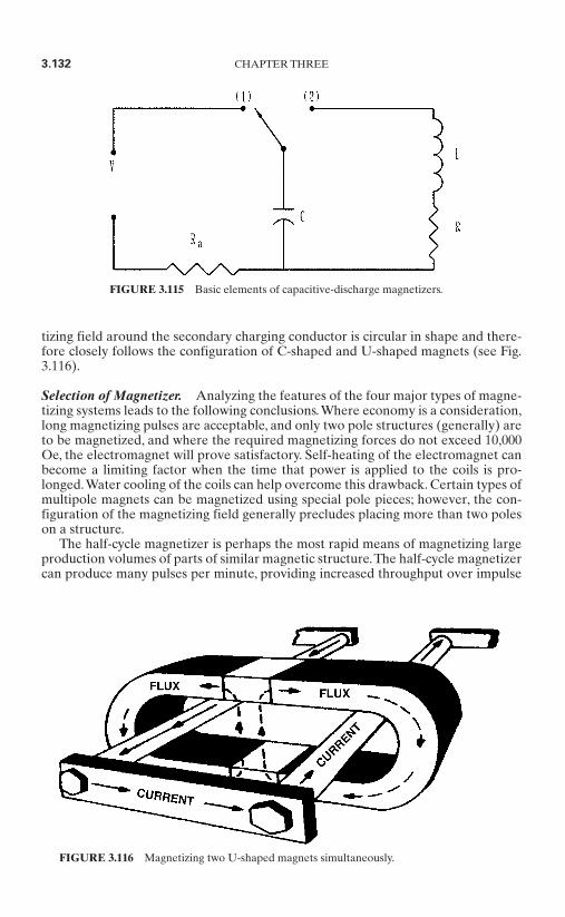
tizing field around the secondary charging conductor is circular in shape and there-fore closely follows the configuration of C-shaped and U-shaped magnets (see Fig.3.116).
Selection of Magnetizer. Analyzing the features of the four major types of magne-tizing systems leads to the following conclusions.Where economy is a consideration,long magnetizing pulses are acceptable, and only two pole structures (generally) areto be magnetized, and where the required magnetizing forces do not exceed 10,000Oe, the electromagnet will prove satisfactory. Self-heating of the electromagnet canbecome a limiting factor when the time that power is applied to the coils is pro-longed.Water cooling of the coils can help overcome this drawback. Certain types ofmultipole magnets can be magnetized using special pole pieces; however, the con-figuration of the magnetizing field generally precludes placing more than two poleson a structure.
The half-cycle magnetizer is perhaps the most rapid means of magnetizing largeproduction volumes of parts of similar magnetic structure.The half-cycle magnetizercan produce many pulses per minute, providing increased throughput over impulse
3.132 CHAPTER THREE
FIGURE 3.115 Basic elements of capacitive-discharge magnetizers.
FIGURE 3.116 Magnetizing two U-shaped magnets simultaneously.
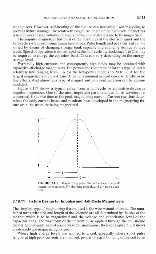
magnetizers. However, self-heating of the fixture can necessitate water cooling toprevent fixture damage.The relatively long pulse length of the half-cycle magnetizeris useful where large volumes of highly permeable materials are to be magnetized.
The impulse magnetizer has most of the attributes of the electromagnet and thehalf-cycle system with some minor limitations. Pulse length and peak current can bevaried by means of changing storage bank capacity and changing storage voltagelevels. Speed of operation is not as rapid as the half-cycle method, since 1 to 20 s maybe required to charge the capacitor bank. Cost can vary depending on the energy-storage level.
Extremely high currents, and consequently high fields, may be obtained withcapacitive-discharge magnetizers.The power-line requirement for this type of unit isrelatively low, ranging from 1 A for the low-power models to 20 to 30 A for thelargest magnetizers required. Line demand is minimal in most cases, with little or noline effects. And almost any type of magnet and pole configuration can be accom-modated.
Figure 3.117 shows a typical pulse from a half-cycle or capacitive-dischargeimpulse magnetizer. One of the most important parameters, as far as waveform isconcerned, is the rise time to the peak magnetizing current. Current rise time deter-mines the eddy current losses and resultant heat developed in the magnetizing fix-ture or in the structure being magnetized.
3.18.11 Fixture Design for Impulse and Half-Cycle Magnetizers
The simplest type of magnetizing fixture used is the wire-wound solenoid. The num-ber of turns, wire size, and length of the solenoid are all determined by the size of themagnet which is to be magnetized and the voltage and capacitance level of thecapacitor bank. The waveform of the current pulse applied through the coil shouldclosely approximate half of a sine wave for maximum efficiency Figure 3.118 showsa solenoid-type magnetizing fixture.
Where high energy levels are applied to a coil, especially where short pulselengths at high peak currents are involved, proper physical bonding of the coil turns
MECHANICS AND MANUFACTURING METHODS 3.133
FIGURE 3.117 Magnetizing pulse characteristics: A = peakmagnetizing current, B = rise time to peak, and C = pulse dura-tion.

is extremely important. The stress forces applied to the coil can be large in somecases, and insufficient bonding can cause the coil to be physically damaged.
A solenoid may be termed an air-wound solenoid or it may be surrounded with aferrous return path to enable higher magnetizing forces to be achieved by the low-reluctance return path. The ferrous return path may provide additional physicalstrength.
The impulse or half-cycle magnetizer’s arc is widely used in the magnetization ofstraight bar magnets.The large amount of energy which can be produced by this typeof magnetizer enables the saturation of unusually large volumes of magnetic mate-rials. Magnetization of straight magnets is usually accomplished in a cavity-type fix-ture employing a coil wound like a solenoid and a soft-iron return path. Thisstructure has high efficiency, since virtually all of the magnetizing force producedpasses through the cavity along the axis of the coil.
Magnets can be magnetized as individual units, in groups, or as completed mag-netic assemblies. Saturation of a completed structure is generally preferred, since thedanger of contamination by ferrous particles during handling is reduced, and demag-netization by open circuiting is prevented. Open-circuiting a magnet refers to theremoval of the keeper or working-gap assembly from the pole ends. This, in effect,applies a demagnetizing force to the magnet and in some cases (determined by themagnet configuration) can cause a loss of as much as 6 percent of residual induction.
The impulse and half-cycle magnetizers also lend themselves to the utilization ofmultipole wound magnetizing fixtures, diagrammed in Fig. 3.119. The multipole fix-ture is used for the magnetization of various sensors, generator rotors, alternatorrotors, synchronous motor rotors, multipole stator assemblies, and a wide variety ofmultipole configurations of a cylindrical, flat, or curved nature.
Where a magnet surface is continuous, not segmented, or has salient poles, thepole location and the polar embrace are determined by the pole-tip configuration ofthe charging fixture.
The polar embrace of a structure which incorporates pole pieces is determined bythe pole pieces themselves. It is usually advantageous, although not always neces-
3.134 CHAPTER THREE
FIGURE 3.118 Solenoid-type wire-wound fixture showing relationship of flux H tocurrent I.

sary, to make the multipole charging fixture from layers of ferrous material ratherthan carve it from a solid block of iron. Stock used may be transformer iron or cold-rolled steel sheets, ranging in thickness form 0.014 to 0.060 in. This mini-mizes eddy current losses and results in more efficient use of the magnetizingenergy. The laminated sheets should be insulated from each other by suitable varnish or other material. Some shorting between laminations may result when the structure is slotted and the cavity is turned, but this will cause only minorlosses.
Multipole magnetizing fixtures can also be made as the so-called single turn, cop-per and iron fixtures. Instead of many turns of wire on each salient pole (for exam-ple, 20 turns of number 16 wire per pole), a heavy conductor (say, having a crosssection of 0.5 in) is convoluted around each pole.This generally entails the necessityof milling and hard-soldering the copper conductor sections. A further accessory isalso required, the low-impedance single-turn fixture. Magnetizing several polessimultaneously can also be achieved using this type of fixture in conjunction withpulse transformers. A typical four-pole fixture is shown in Fig. 3.120.
A multipole cylindrical magnet can be charged by either method; however, themethod used will have an impact on the flux distribution characteristics of the mag-net or assembly. It is important to know how this may impact the end product per-formance. During the early product development stage, testing of differentmagnetizing techniques will allow the design engineer to determine whether betterperformance can be achieved with one technique over another. As an example,a two-pole motor can be magnetized from the outside in using a wire-wound
MECHANICS AND MANUFACTURING METHODS 3.135
FIGURE 3.119 Four-pole laminated-steel wire-wound fixture.
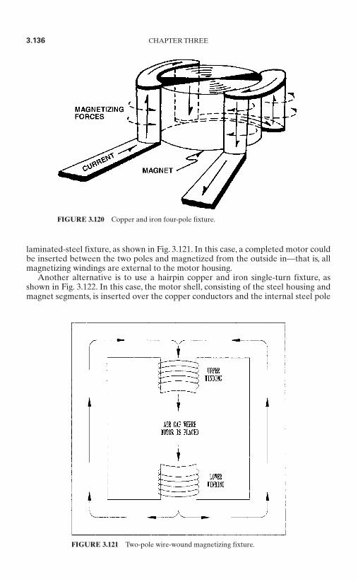
laminated-steel fixture, as shown in Fig. 3.121. In this case, a completed motor couldbe inserted between the two poles and magnetized from the outside in—that is, allmagnetizing windings are external to the motor housing.
Another alternative is to use a hairpin copper and iron single-turn fixture, asshown in Fig. 3.122. In this case, the motor shell, consisting of the steel housing andmagnet segments, is inserted over the copper conductors and the internal steel pole
3.136 CHAPTER THREE
FIGURE 3.120 Copper and iron four-pole fixture.
FIGURE 3.121 Two-pole wire-wound magnetizing fixture.
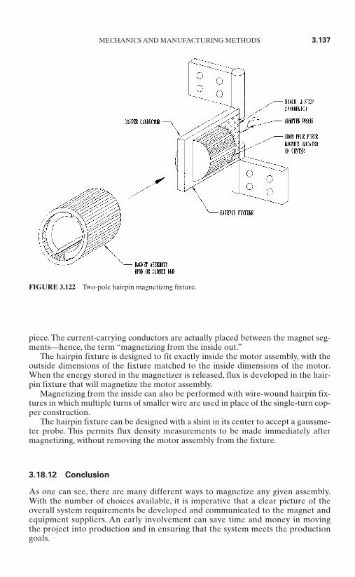
piece. The current-carrying conductors are actually placed between the magnet seg-ments—hence, the term “magnetizing from the inside out.”
The hairpin fixture is designed to fit exactly inside the motor assembly, with theoutside dimensions of the fixture matched to the inside dimensions of the motor.When the energy stored in the magnetizer is released, flux is developed in the hair-pin fixture that will magnetize the motor assembly.
Magnetizing from the inside can also be performed with wire-wound hairpin fix-tures in which multiple turns of smaller wire are used in place of the single-turn cop-per construction.
The hairpin fixture can be designed with a shim in its center to accept a gaussme-ter probe. This permits flux density measurements to be made immediately aftermagnetizing, without removing the motor assembly from the fixture.
3.18.12 Conclusion
As one can see, there are many different ways to magnetize any given assembly.With the number of choices available, it is imperative that a clear picture of theoverall system requirements be developed and communicated to the magnet andequipment suppliers. An early involvement can save time and money in movingthe project into production and in ensuring that the system meets the productiongoals.
MECHANICS AND MANUFACTURING METHODS 3.137
FIGURE 3.122 Two-pole hairpin magnetizing fixture.

3.19 CAPACITIVE-DISCHARGE MAGNETIZING*
3.19.1 Getting the Most Out of Your Magnets
Magnets are useless until they are magnetized. No clever or innovative electricmotor design can overcome the fact that if the magnets are not magnetized, themotor will not work. While enormous resources are often committed to electricmotor design, optimization, and production efficiencies, it is easy to overlook themagnetizing process. Improperly magnetized magnets can offset gains made indesign and production engineering. Advancements in higher-energy-product mag-nets also create new challenges to motor producers who chose to take advantage ofthese materials. This section will assist the electric motor producer in finding theoptimal magnetizing process for motor production, improving the performance andreliability of the final product.
A magnet is magnetized when it is exposed to a large magnetic field. Large mag-netic fields require large electric currents, which require large amounts of energy. Amagnetizing system converts energy from a power supply into magnetic fields usedto magnetize the magnet. Magnetizing systems consist of two basic components: themagnetizer, which stores and releases energy in the form of an electric current, andthe magnetizing coil, which converts the large electrical current into magnetic fieldsto magnetize the magnets. The magnetizer can be thought of as an energy storageand release system, while the magnetizing coil directs the energy from the magne-tizer into useful work that magnetizes the magnets.
Let us first consider the magnetizer, which stores energy to produce currents.There are several ways to store electrical energy:
Batteries Utility power lines Inductors Rotating devices (generators) Flywheels Electrical capacitors
Given the large fields usually required for the magnetizing process, pulse cur-rents rather than continuous currents are used to create magnetizing fields. Becauseof the brief but intense currents used in the magnetizing process, electrical capaci-tors have been the usual component used to store electrical energy in magnetizingsystems. Figure 3.123 shows a block diagram of a basic magnetizing system. Theinstantaneous energy in a pulsed magnetic field can be extremely high. Five millionwatts is not uncommon.
3.19.2 Storing Electrical Energy in Capacitors
Since magnetizing systems usually use electrical capacitors to store energy, they areoften referred to as capacitive-discharge magnetizing (CDM) systems. The energystored in a capacitor or bank of capacitors is mathematically expressed by the for-mula
3.138 CHAPTER THREE
* Section contributed by Derrick Peterman and Leon Jackson, LDJ Electronics.
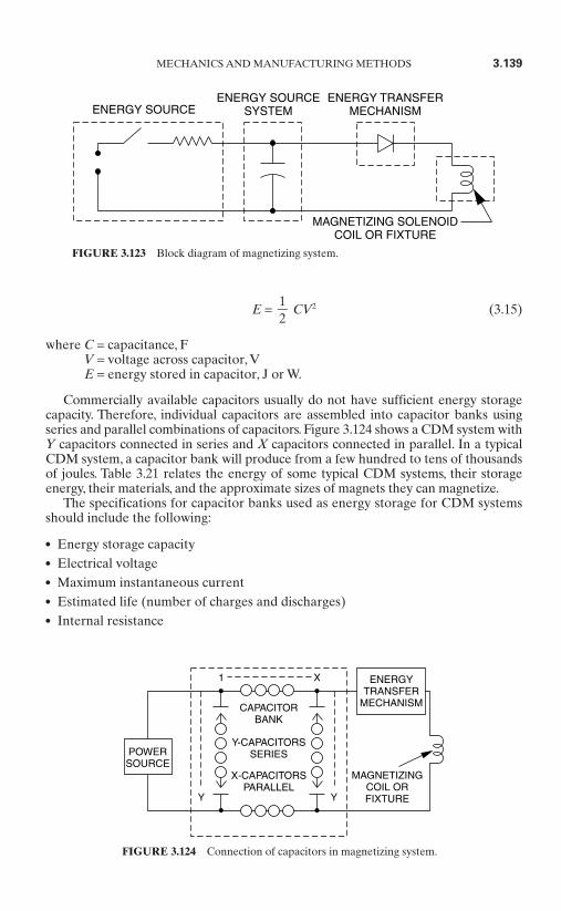
E = CV2 (3.15)
where C = capacitance, FV = voltage across capacitor, VE = energy stored in capacitor, J or W.
Commercially available capacitors usually do not have sufficient energy storagecapacity. Therefore, individual capacitors are assembled into capacitor banks usingseries and parallel combinations of capacitors. Figure 3.124 shows a CDM system withY capacitors connected in series and X capacitors connected in parallel. In a typicalCDM system, a capacitor bank will produce from a few hundred to tens of thousandsof joules. Table 3.21 relates the energy of some typical CDM systems, their storageenergy, their materials, and the approximate sizes of magnets they can magnetize.
The specifications for capacitor banks used as energy storage for CDM systemsshould include the following:
Energy storage capacity Electrical voltage Maximum instantaneous current Estimated life (number of charges and discharges) Internal resistance
12
MECHANICS AND MANUFACTURING METHODS 3.139
ENERGY SOURCEENERGY SOURCE
SYSTEMENERGY TRANSFER
MECHANISM
MAGNETIZING SOLENOIDCOIL OR FIXTURE
FIGURE 3.123 Block diagram of magnetizing system.
Y
Y-CAPACITORSSERIES
X-CAPACITORSPARALLEL
CAPACITORBANK
MAGNETIZINGCOIL ORFIXTUREY
1 X ENERGYTRANSFER
MECHANISM
POWERSOURCE
FIGURE 3.124 Connection of capacitors in magnetizing system.
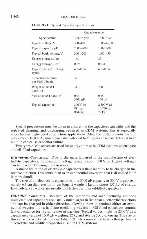
Special precautions must be taken to ensure that the capacitors can withstand therepeated charging and discharging required in CDM systems. This is especiallyimportant in high-speed production applications. Also, the instantaneous currentmay exceed 10,000 A, which can cause internal heating in capacitors. Internal heatbuildup can cause capacitor failure.
Two types of capacitors are used for energy storage in CDM systems, electrolyticand oil-filled capacitors.
Electrolytic Capacitors. Due to the materials used in the manufacture of elec-trolytic capacitors, the maximum voltage rating is about 500 V dc. Higher voltagescan be reached by using them in series.
A major limitation of electrolytic capacitors is their inability to be charged in thereverse direction.This limits them to an exponential waveform that is discussed laterin more detail.
The size of an electrolytic capacitor with a 3500 µF capacity at 300 V is approxi-mately 6.7 cm diameter by 14 cm long. It weighs 1 kg and stores 157.5 J of energy.Electrolytic capacitors are usually much cheaper than oil-filled capacitors.
Oil-Filled Capacitors. Because of the materials and manufacturing methodsused, oil-filled capacitors are usually much larger in size than electrolytic capacitorsand can be charged in either direction, allowing them to produce either an expo-nential waveform or a half-sine oscillating waveform. Oil-filled capacitors containless capacitance for the same size of package. Typical values might be 2500 V at acapacitance value of 1600 µF, weighing 22 kg and storing 500 J of energy. The size ofthis capacitor is 13 × 34 × 33 cm. Table 3.21 lists a number of factors that pertain toelectrolytic and oil-filled capacitors used in CDM systems.
3.140 CHAPTER THREE
TABLE 3.21 Typical Capacitor Specifications
Capacitor type
Specification Electrolytic Oil-filled
Typical voltage, V 300–450 1000–45,000
Typical capacity, µF 2000–4000 100–1000
Typical bank voltage, V 300–1200 1000–450
Energy storage, J/kg 163 23
Energy storage, J/cm3 0.19 0.034
Typical charge/discharge 4 million 6 millioncycles
Capacitors required 32 10per 5000-J bank
Weight of 5000-J 31 220bank, kg
Size of 5000-J bank, m3 0.04 0.153500 µF 160 µF
Typical capacitor 300 V dc 2,500 V dc811 cm3 14,730 cm3
0.96 kg 22 kg
Most voltages used by CDM systems require extreme care, both in operator safe-guards and fixture design. The higher operating voltages of oil-filled capacitorsincrease the precautions that must be taken. Also, the cost of components increasesas the voltage increases.
Electrolytic capacitor systems weigh less and occupy less space than oil-filledcapacitor systems. Energy storage per unit of weight or volume is usually not a criti-cal factor in choosing an energy storage system. However, the lower energy densityof oil-filled capacitors can contribute to a longer capacitor life and increasedcharge/discharge cycles for oil-filled capacitor energy storage systems. This advan-tage of lower energy density becomes more crucial when the application requireslarge peak currents and rapid cycle rates, which tend to shorten capacitor life.
In addition to longer capacitor life, oil-filled capacitors have the advantage ofproducing either an exponential, half-sine, or oscillating waveform. Since elec-trolytic capacitors can produce only the exponential waveform, most of the energyfrom the capacitor bank is dissipated into the magnetizing coil each cycle, whilethe half-sine waveform dissipates only a small portion of the capacitor-bankenergy into the magnetizing coil. The half-sine energy that is not dissipated by themagnetizing coil recharges the capacitor bank in the opposite direction. Withproper electronic circuitry, it can then be discharged through the magnetizing coilin the next cycle. The advantages are savings in input energy and reduced heatingin the magnetizing coil.
3.19.3 Connecting the Magnetizer to the Magnetizing Coil
The switch to transfer energy from the energy storage system to the magnetizing coilcan range from very elementary to very sophisticated. In one application, the switchwas a short piece of magnet wire about 2 mm in diameter. The wire was clampedbetween two blocks. The energy storage system was a bank of lead-acid batteries,with a 2-mm length of copper coil in series with a magnetizing coil. In fractions of asecond, as the current built up in the circuit, the magnet wire became hot to the pointof violent disintegration. When the magnet wire disintegrated, it worked as a switchto shut off the electric current so that neither the magnetizing coil nor the energysource would be damaged. By choosing the size of magnet wire, the peak currentcould be controlled.With this technique, safety glasses are an absolute must becausethe disintegrating wire causes copper to be splattered about during each magnetiz-ing cycle.
A far less spectacular but preferable switching method is to use a solid-state elec-tronic switch, such as an SCR. SCRs are easy to control electronically and are veryreliable. In some CDM systems, an ignitron vacuum tube is used. The ignitron tubehas some disadvantages:
It has a limited life. It uses mercury, which is a hazardous material. It may require water cooling.
However, the ignitron will take more punishment in terms of exceeding its elec-trical ratings than an SCR. If its specified electrical ratings are exceeded, an SCRmay be destroyed. If the ratings of an ignitron are exceeded, it may sustain onlyminor damage and continue to operate.
CDM systems can be designed to produce magnetic field pulses specific to theapplication. The factors to be considered are the following:
MECHANICS AND MANUFACTURING METHODS 3.141
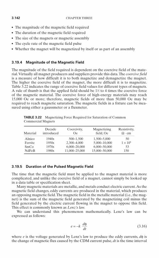
The magnitude of the magnetic field required The duration of the magnetic field required The size of the magnets or magnetic assembly The cycle rate of the magnetic field pulse Whether the magnet will be magnetized by itself or as part of an assembly
3.19.4 Magnitude of the Magnetic Field
The magnitude of the field required is dependent on the coercive field of the mate-rial.Virtually all magnet producers and suppliers provide this data.The coercive fieldis a measure of how difficult it is to both magnetize and demagnetize the magnet.The higher the coercive field of the magnet, the more difficult it is to magnetize.Table 3.22 indicates the range of coercive field values for different types of magnets.A rule of thumb is that the applied field should be 11⁄2 to 4 times the coercive forceof the magnetic material. The coercive force of high-energy materials may reach15,000 Oe or more; therefore, magnetic fields of more than 50,000 Oe may berequired to reach magnetic saturation. The magnetic fields in a fixture can be mea-sured using either a gaussmeter or a fluxmeter.
3.19.5 Duration of the Pulsed Magnetic Field
The time that the magnetic field must be applied to the magnet material is morecomplicated, and unlike the coercive field of a magnet, cannot simply be looked upin a data table or specification sheet.
Many magnetic materials are metallic, and metals conduct electric current.As themagnetic field changes, eddy currents are produced in the material, which producesan opposing magnetic field.The magnetic field in the metallic material (i.e., the mag-net) is the sum of the magnetic field generated by the magnetizing coil minus thefield generated by the electric current flowing in the magnet to oppose this field.This effect is commonly known as Lenz’s law.
We can understand this phenomenon mathematically. Lenz’s law can beexpressed as follows:
e = −k (3.16)
where e is the voltage generated by Lenz’s law to produce the eddy currents, dφ isthe change of magnetic flux caused by the CDM current pulse, dt is the time interval
dφdt
3.142 CHAPTER THREE
TABLE 3.22 Magnetizing Force Required for Saturation of CommonCommercial Magnets
Decade Coercivity, Magnetizing Resistivity,Material introduced Oe field, Oe Ω ⋅ cm
Alnico 1940s 500–1,500 1,500–5,000 50Ferrite 1950s 2,300–4,000 5,000–10,000 1 × 10⁶
SmCo 1970s 6,000–20,000 6,000–50,000 53NdFeB 1980s 11,000–25,000 15,000–50,000 150
of the magnetic flux change, and k is a simple proportionality constant. Note that thenegative sign in front of k is a result of the eddy currents opposing the change inmagnetic flux.
It can be shown that eddy currents are proportional to the rate of change of mag-netic field with respect to time by
Ieddy = K (3.17)
where Ieddy is the magnitude of the eddy current and dHCDM is the change in the mag-netic field produced by the magnetizer over a time interval dt. From Eq. (3.17), wesee that if
(3.18)
the rate of change of the magnetic field produced by the magnetizer is high, the sizeof the eddy currents will also be high. Since the eddy currents act to oppose theapplied field, large eddy currents can cancel out a substantial fraction of the fieldproduced by the magnetizing fixture. This problem can be overcome by simplyreducing the rate at which the magnetic field increases. This requires a longer mag-netizing pulse width. However, lengthening the duration of the magnetic field pulsecauses heating in the magnetizing coil.
While eddy currents complicate the magnetization process, they can be dealt witheffectively. Since eddy currents depend on the resistivity of the magnet, ferrite mag-nets, which are electrical insulators, are highly immune to the effects of eddy currentsduring the magnetization process. Unfortunately, alnico, samarium cobalt (SmCo) andneodymium iron boron (NdFeB) magnets are all decent conductors, as indicated inTable 3.22, and so eddy currents are produced in these materials during pulsed mag-netization. Since alnico magnets have relatively low coercive fields, the effect of eddycurrents can be overcome by simply using large enough applied fields to overcome theopposing fields that result from the eddy currents. Eddy currents are more difficult toovercome with SmCo and NdFeB magnets.
The difficulty with magnetizing SmCo and NdFeB magnets is that since thesemagnets have such large coercivities, it is highly impractical to simply “overpower”the effect of the eddy currents. This creates more problems than it solves. To beginwith, extremely large amounts of energy must be stored and released to overcomeeddy currents in this manner. As we shall soon see, this requires a very large mag-netizer, which is both expensive and takes up potentially valuable space on the fac-tory floor. Huge currents flowing through the magnetizing fixture dissipatetremendous heat—heat that can damage the fixture, even possibly causing catas-trophic failure. If the magnets are in a steel assembly, large forces due to the rapidlycharging magnetic fields can cause flexing of the steel assembly, which can breakthe magnets inside.At the very least, additional time between magnetizing firings isrequired for the fixture to cool. This reduces production throughput. An effectivemethod of magnetizing rare earth magnets balances the large currents required toproduce a large field against longer pulse times with reduced eddy current losseffects.
A seldom-mentioned advantage of bonded rare earth magnets is that they arenonconductive; therefore, eddy currents are usually small in these magnets.The rub-ber or plastic binders are insulating and electrically isolate the conducting grainsfrom one another. Bonded magnets are easier to magnetize than similar-sized bulkmagnets for this reason.
dHCDMdt
dHCDMdt
MECHANICS AND MANUFACTURING METHODS 3.143
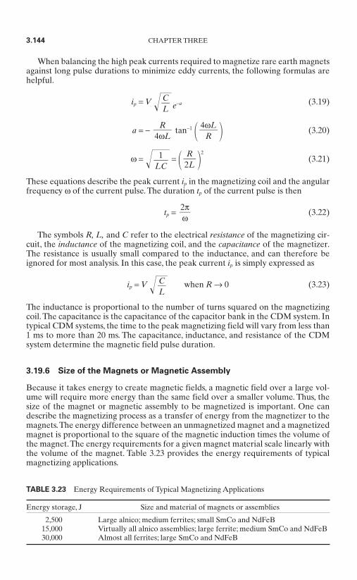
When balancing the high peak currents required to magnetize rare earth magnetsagainst long pulse durations to minimize eddy currents, the following formulas arehelpful.
ip = V e−a (3.19)
a = − tan−1 (3.20)
ω = = 2
(3.21)
These equations describe the peak current ip in the magnetizing coil and the angularfrequency ω of the current pulse. The duration tp of the current pulse is then
tp = (3.22)
The symbols R, L, and C refer to the electrical resistance of the magnetizing cir-cuit, the inductance of the magnetizing coil, and the capacitance of the magnetizer.The resistance is usually small compared to the inductance, and can therefore beignored for most analysis. In this case, the peak current ip is simply expressed as
ip = V when R → 0 (3.23)
The inductance is proportional to the number of turns squared on the magnetizingcoil.The capacitance is the capacitance of the capacitor bank in the CDM system. Intypical CDM systems, the time to the peak magnetizing field will vary from less than1 ms to more than 20 ms. The capacitance, inductance, and resistance of the CDMsystem determine the magnetic field pulse duration.
3.19.6 Size of the Magnets or Magnetic Assembly
Because it takes energy to create magnetic fields, a magnetic field over a large vol-ume will require more energy than the same field over a smaller volume. Thus, thesize of the magnet or magnetic assembly to be magnetized is important. One candescribe the magnetizing process as a transfer of energy from the magnetizer to themagnets.The energy difference between an unmagnetized magnet and a magnetizedmagnet is proportional to the square of the magnetic induction times the volume ofthe magnet.The energy requirements for a given magnet material scale linearly withthe volume of the magnet. Table 3.23 provides the energy requirements of typicalmagnetizing applications.
CL
2πω
R2L
1LC
4ωL
RR
4ωL
CL
3.144 CHAPTER THREE
TABLE 3.23 Energy Requirements of Typical Magnetizing Applications
Energy storage, J Size and material of magnets or assemblies
2,500 Large alnico; medium ferrites; small SmCo and NdFeB15,000 Virtually all alnico assemblies; large ferrite; medium SmCo and NdFeB30,000 Almost all ferrites; large SmCo and NdFeB
3.19.7 Cycle Rate of the Magnetic Field Pulse
The cycle rate of the magnetic field pulse is an important consideration for themagnetizing system. For high-volume electric motor production, the magnetizingsystem must be designed to handle a high cycle rate. For prototype and laboratoryuse where the cycle rate is of little importance, a more versatile magnetizing sys-tem than that used for production purposes is usually preferred. The rate of mag-netizer charging is an important consideration in the choice of the capacitorsused.
Any energy that is not dissipated in the magnetizing coil as heat or energy tomagnetize the magnets must be restored in the capacitor bank. This fact has advan-tages and disadvantages. Since only a small part (as little as 10 percent) of the energyis dissipated in the magnetizing coil or used to magnetize the magnets, about 90 per-cent of the energy will be returned to the capacitor bank. This greatly reduces thesource energy needed to recharge the capacitor bank. However, the capacitor bankis now charged in the opposite direction, and the next magnetic pulse will be in theopposite direction unless the proper electronic circuitry is employed to reverse thecurrent through the magnetizing coil.
Since electrolytic capacitors cannot be charged in the reverse direction, a CDMsystem that produces a half-sine waveform must use oil-filled capacitors. The addi-tional cost of the electronics and oil-filled capacitors can double the capital cost ofa CDM system. The operating energy savings are usually not sufficient to warrantthe additional capital cost of using the half-sine waveform, unless technicalreasons warrant its use. If magnetizing-coil heating is a serious problem, the use of oil-filled capacitors and the half-sine waveform may well be the best choice.Where magnetizing-coil heating is not a problem, even when refrigerator cooling isrequired, electrolytic capacitors and the exponential waveform are usually the mostcost-effective solution.
The cycle rate mostly affects the heat generated in the magnetizing coil.The cyclerate for production CDM systems varies from a few parts per hour to 1 or 2 s perpart. For most applications, with cycle rates above 200 parts per hour, the magnetiz-ing fixture will require cooling. However, the space available for the magnetizingcoil and the magnitude of the magnetic field required can greatly alter this generalrule. The most convenient cooling method is by pumping a refrigerated liquidthrough the magnetizing fixture.
3.19.8 Magnetizing Magnets Individually or as an Assembly
A magnet which is built into the final assembly, such as a dc motor, is usually harderto magnetize than the magnet by itself.This can result in a larger CDM system, lowercycle rates, or more complex magnetizing coils and fixtures.
Metallic magnet assembly housing will dissipate energy during the magnetizingprocess in the form of eddy currents. This is especially true in the case of magneticmetals, such as steel alloys (including magnetic stainless steels) and laminations.Nonmagnetic metals such as aluminum are also a source of eddy current loss, but toa lesser extent than magnetic steels.
However, the advantages gained by assembling unmagnetized magnets are usu-ally more than worth the payment required in magnetizing problems. It is difficultto assemble magnets once they are magnetized. In fact, this is a potentially dan-gerous operation to do by hand. This is especially true with large magnets andmagnets with high energy products, which are very difficult to handle when mag-netized.
MECHANICS AND MANUFACTURING METHODS 3.145
3.19.9 Magnetizing Coils
The magnetizing coil is usually the weak link in a CDM system. It is on the receivingend of an electrical energy jolt that can reach an instantaneous value of 5 million W.The magnetic forces caused by the high currents in the magnetizing coil windingscan cause physical movement of the windings, resulting in shorted turns or causingthe windings to open.
The sheer number of electrons flowing in the windings can cause the coil windingto blow apart if the windings have sharp bends. Heat buildup can soften encapsulat-ing epoxy, allowing physical movement of the conductors. Heat buildup can alsoweaken the winding insulation, creating the possibility of shorted turns. The highcurrent pulses (a few hundred to more than 10,000 A) will cause instantaneous heat-ing of weak spots in the magnetizing coil winding. These hot spots can be at connec-tion points or at flaws in the copper conductor.
The magnetizing coil must be designed to do the following:
Withstand a few hundred to several thousand volts. Accept a few hundred to several thousand amperes. Withstand the mechanical forces caused by the electrical current flow. Produce the magnitude of magnetic field required for the material being magne-
tized. Generate a magnetic field pulse of sufficient duration to allow the magnetic field
to fully saturate all of the magnetic material. Have a sufficient cooling system so that the required production cycle rates can be
realized. Be safe when operators come in contact with it. The safety issues must deal with
both the electrical voltages and physical forces.
The high voltages involved require that special attention be given to insulation.The proper wire should be used, with insulation specifications that meet or exceedthe maximum voltage of the CDM system. Special care must be taken when makingconnections. All metal parts of the fixture should be securely grounded with wireequal or superior to the magnetizing coil conductors in size and insulation specifica-tions. The operator should be precluded from coming in contact with the magnetiz-ing conductors. This can be done by encapsulating the magnetizing coil in epoxy,placing the magnetizing coil out of reach of the operator during the magnetizingfield pulse, or both. It is usually necessary to encapsulate the magnetizing coil inhigh-strength epoxy. This encapsulation serves two purposes:
It keeps the conductors from moving during the magnetic field pulses. It provides safety for the operator.
The magnitude of the magnetic field is determined by the amount of energyapplied to the magnetizing coil. The duration of the pulse is greatly affected by thenumber of turns on the magnetizing coil. The main variables of the magnetizing coilare the number of turns and its size. The general rule for a magnetizing coil of fixedsize is that when the turns increase, the conductor size decreases, the peak fielddecreases, and the pulse duration increases.
The design of magnetizing coils and fixtures requires careful consideration ofconductive materials that may be in the magnetic circuit. Conductive materials, thesize of the part to be magnetized, and its shape should also be taken into account
3.146 CHAPTER THREE

when designing magnetizing fixtures and coils. All coils and fixtures should beimpregnated with epoxy to ensure that conductors cannot move during the magneticfield pulse.
In some magnetizing applications, it is advantageous to use steel poles to increasethe magnetic field produced by the magnetizing coil. Care must be taken when usingsteel pole pieces. The steel pole piece will increase the inductance of the magnetiz-ing coils; introducing steel pole pieces into a magnetizing process may, therefore,require some change in the magnetizer capacitance. Since steel pole pieces are asource of eddy current loss, stacked steel laminations are recommended instead ofsolid pole pieces. Stacked laminations reduce the eddy current losses and allowlarger fields to be produced.
Multiple poles can be magnetized with the proper magnetizing fixture design.Magnetizing coils can be wound around two pole pieces. The magnet to be magne-tized completes the magnetic circuit. When the current pulse passes through themagnetizing coils, north and south poles are created in the magnet. Multiple polescan be created on a single magnet by repeating this design along the length or cir-cumference of the magnet. Figure 3.125 illustrates a simple example of pole creationat the ends of a magnet.
In general, the fields generated by the magnetizing coils should be oriented in theoptimal direction to magnetize the magnet. This optimal direction is determined bythe magnet design. If the magnetizing fields do not magnetize the magnet in the ori-entation specified in the design, the motor may very likely not perform as designed.A poorly conceived magnetizing coil design can rob a motor of performance.
MECHANICS AND MANUFACTURING METHODS 3.147
FIGURE 3.125 A simple example of magnetizingpoles along the length of a magnet. The horizontalmagnet completes a magnetic circuit between the twovertical magnetizing pole pieces.