mechanistic design for concrete crossties
TRANSCRIPT

Mechanistic design for Concrete Crossties
Steven MelniczukRicardo J. Quirós-Orozco
2018 International Crosstie and Fastening System Symposium
Application for Amtrak’s Shared Corridor Application

Engineering
RailTEC at Illinois | 2
Concrete Ties – Amtrak’s History

Engineering
RailTEC at Illinois | 3
Slide Outline
Timeline of Concrete Tie Manufacture
Concrete Tie Problems
Concrete Tie Design Changes
Elastic Fasteners
Shoulders
Tie Pads and Insulators
Future Considerations

Engineering
RailTEC at Illinois | 4
Timeline of Manufacture
First concrete tie manufactured & installed – 1978
Manufacturers:–Santa Fe San Vel: 1978 to 1983 ~ 1.0 million–Lonestar: 1983 to 1986 ~ 0.3 million–Rocla: 1990 to 2000 ~ 1.4 million–Rocla: 2003 to present ~ 2.3 million
Total concrete ties purchased to date ~ 5.0 million
Total concrete ties in track 1056 miles NEC, 2.8 M and 114 miles Harrisburg Line, 300 K

Engineering
RailTEC at Illinois | 5
Concrete Tie Problems

Engineering
RailTEC at Illinois | 6
Concrete Tie Problems

Engineering
RailTEC at Illinois | 7
Concrete Tie Problems - Operations
Amtrak has contracted with HNTB for tie evaluation by qualified inspectors
Tie evaluation done by walking with Amtrak
Data accumulated to track trends, identify critical areas, program replacement programs
CLT used for periodic testing and monitoring
UIUC is under contract to review and test current tie design and specification

Engineering
RailTEC at Illinois | 8
Concrete Tie Problems –San Vel
Approx. 1,000,000 ties manufactured between 1978 to 1983
Spider cracking with slow progression to failure
Useful life span of a concrete tie is predicted to be 50 yrs.
Continuous monitoring and inspection until replacement
Removed and tested for strength periodically

Engineering
RailTEC at Illinois | 9
Concrete Tie Problems – Lone Star
Approx. 300,000 ties manufactured between 1982 and 1986Cracking first detected in 1986 Spider cracking with slow progression to failure within a few yearsAttributed to an alkali-silicone reaction (ASR) and low air entrainment All ties installed in stretches replaced between 1990 & 1995Others similarly afflicted (CSX, LIRR, Transit Systems)

Engineering
RailTEC at Illinois | 10
Concrete Tie Problems – Rocla
Approximately 1,400,000 ties manufactured between 1990 and 2000
Population of cracking ties & year of first detection:
– 1990 to 1992: 360,000 ties / cracks detected in 1999 (7+ years from manufacture)
– 1993 to 1994: 323,000 ties / cracks detected in 2006 (12+ years from manufacture)
– 1996: 133,000 ties / cracks detected in 2007 (11 years from manufacture)
– 1997: 118,000 ties / cracks detected in 2001 (4 years from manufacture)
– 1998 to 1999: 314,000 ties / cracks detected in 2007 (8+ years from manufacture)
Most ties exhibit hairline cracking with a slow propagation rate
Some ties exhibit spider cracking with a more rapid propagation rate (predominantly the ties manufactured in 1997)
Tie cracking attributed to ASR and DEF, result of contamination in the fine aggregate and possible high curing temperatures
Others similarly afflicted (Metro North, LIRR, MBTA)

Engineering
RailTEC at Illinois | 11
Concrete Tie Design Changes
Santa Fe San Vel 1978-83
Lonestar 1983-86
Rocla 1990-2000
New Rocla 2003 to present
New Amtrak Tie 2018-beyond?

Engineering
RailTEC at Illinois | 12
Concrete Tie Design Changes

Engineering
RailTEC at Illinois | 13
Concrete Tie Design Changes

Engineering
RailTEC at Illinois | 14
Concrete Tie Design Changes

Engineering
RailTEC at Illinois | 15
Concrete Tie Design Changes

Engineering
RailTEC at Illinois | 16
Past Concrete Tie Design Changes
Last major change to Amtrak Tie Specification was in 2003 Design change from 8 7-strand reinforcing wires to 24 individual
indented reinforcing wires to increase tensile strength Established tighter limitations on pre-set curing temperatures and
new control system installed to closely monitor curing temperatures Use of manufactured sand (fine aggregate) to eliminate most all
potential reactive contaminants that could contribute to ASR/DEF reactivity Use of up to 20% but not less than 15% fly ash in the cementitious
portion of the mix for even greater resistance to formation of ASR and DEF Additional third party (CTL) testing of materials and hardened
concrete Increase Q/C process Increase air entrainment from 4%-6% to 4%-7%

Engineering
RailTEC at Illinois | 17
Concrete Tie Design Changes

Engineering
RailTEC at Illinois | 18
Concrete Tie Design Changes

Engineering
RailTEC at Illinois | 19
Elastic Fasteners
1978-1986 PR 601-A
1990- 1995 e 2055
Mid 1995 to present FastClip
Engineering
RailTEC at Illinois | 20
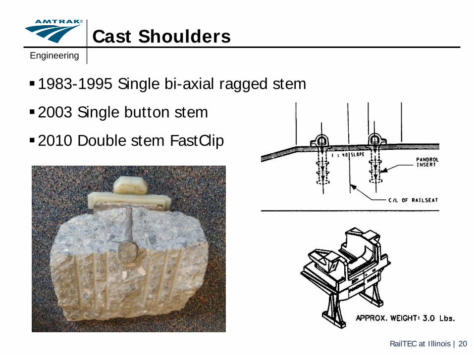
Cast Shoulders
1983-1995 Single bi-axial ragged stem
2003 Single button stem
2010 Double stem FastClip

Engineering
RailTEC at Illinois | 21
Tie Pads and Insulators
5 mm Ohio rubber pad
6 1/2 mm irradiated EVA pad
6 1/2 mm polyurethane pad (KD, WB)

Engineering
RailTEC at Illinois | 22
Room for Improvements?
Consider possible tie design change
Under Tie Pads
Post Tension Vs Prestress
Wire placement within the tie
Fiber Reinforcement
Geometry changes
Fastening systems
Tie Pads and Insulators

Engineering
RailTEC at Illinois | 23
Future Consideration
Continue third party concrete tie testing
Continue project with UIUC/RailTEC on new tie design
Testing with under tie pads
Compare ride quality data before and after UTP installation
Data collection technology improvements

RailTEC at Illinois | 24
The Mechanistic Approach
Laboratory Experimentation
(Capacity)
Field Experimentation
(Demand)Theoretical
Optimization
Specification Improvement
Industry Involvement
Prototype Development
Field and Experimental
testing

RailTEC at Illinois | 25
Laboratory Experimentation
► Baseline for experimental matrix is the current AREMA design validation sequence of tests (4.9.1)
► Additional tests (developed at UIUC) were added to facilitate a quantitative comparison of performance• Load at first crack• Load vs. deflection
curves at the center and the rail seat
Overview

RailTEC at Illinois | 26
306 314381
487
374436
949
672
888
0
100
200
300
400
500
600
700
800
900
1000
Rocla CT10 (Amtrak) Rocla 101L (BNSF) CXT 505S (UPRR)
Ben
ding
Mom
ent (
Kip
*in)
Specification Laboratory First Crack Laboratory UltimateAmtrak CT-10 Heavy Haul 1 Heavy Haul 2
Laboratory ExperimentationRail Seat Positive Testing (RS+)

RailTEC at Illinois | 27
Laboratory ExperimentationCenter Negative Testing (C-)
208 230 224
347 321 296
637
530 509
0
100
200
300
400
500
600
700
800
900
1000
Rocla CT10 (Amtrak) Rocla 101L (BNSF) CXT 505S (UPRR)
Ben
ding
Mom
ent (
Kip
*in)
Specification Laboratory First Crack Laboratory UltimateAmtrak CT-10 Heavy Haul 1 Heavy Haul 2

RailTEC at Illinois | 28
Field Experimentation
Wheel Impact Load Detectors (WILD)
UIUC Field Instrumentation Site

RailTEC at Illinois | 29
Field Experimentation
► Data analyzed from 1 Jan to 30 June 2017
► Sites:• Edgewood, MD• Marcus Hook, PA• Mansfield, MA
► 54,156 trains► 2,210,687 Axles► 36.6 Million Gross Tons
(MGT)
WILD Results Overview

RailTEC at Illinois | 30
Field ExperimentationWILD Site Results-Wheel Load Data

RailTEC at Illinois | 31
• Site characteristics:
– Track 2 (typically northbound)
– Maximum allowable speed:125 mph (201 km/h)
– Tangent
– Grade: 0.1%
• Traffic during data collecting phase:
• 4,612 trains, 180,362 Axles
• 13 December 2016 –17 May 2017
• 4.5 MGT out of 7.6 MGT totalfor the same time period.
Crosstie Bending Strain
ThermocoupleLaser Trigger
1
(Ambient Temperature)
2 3 4 5 67
A
E
C
Field ExperimentationInstrumented Crossties

RailTEC at Illinois | 32
Field experimentationInstrumented Crossties-Center Bending Moments

RailTEC at Illinois | 33
Field experimentationInstrumented Crossties-Center Bending Moments

RailTEC at Illinois | 34
Field Experimentation
► Using approach detailed by Gao et al. (2015) support conditions on site were estimated from strain gauge data
► Known parameters: 5 discrete strain locations and 2 rail seat loads► Results are given in terms of percentages of support under 6 discrete bins
Support conditions back calculator
Strain Gauge
Rail Seat Load Rail Seat Load
Bin 1 Bin 2 Bin 3 Bin 4 Bin 5 Bin 6

RailTEC at Illinois | 35
Field ExperimentationSupport conditions back calculator

RailTEC at Illinois | 36
Field Demand EstimationPotential Variability in Support Conditions
Good Rail Seat support Lack of Center Sup.
Lack of Rail Seat Support Moderate Center Binding

RailTEC at Illinois | 37
Field Demand EstimationExtrapolated Center Demand

RailTEC at Illinois | 38
Field Demand EstimationExtrapolated Rail Seat Demand

RailTEC at Illinois | 39
Theoretical Optimization Framework
► Analysis tool for optimization of current design
► Reduces capacity to field measured values
► Maximizes cost reduction► Constrains
• Use of same form- Reduce depth- Reduce wires
► Best suited for reusing forms for different projects
► Theoretical model in developent
H1 H2

RailTEC at Illinois | 40
Theoretical Optimization Framework

RailTEC at Illinois | 41
Theoretical Optimization Framework
0
5
10
15
20
25
0% 10% 20% 30% 40%
Cos
t red
uctio
n [$
/tie]
Strength Reduction [%]
24 wires
22 wires
20 wires
18 wires
16 wires

RailTEC at Illinois | 42
Practical Optimization Development
► Reducing capacity is not appealing► It limits the potential increases in
weight, capacity or speeds
► Quantifying the reserve capacity for handling future increased demand is more appealing
► Optimization is based around the objective of getting same capacity with less or the same amount of materials
► Two approaches• Incremental optimization of the
current design• Clean slate design

RailTEC at Illinois | 43
Practical Optimization Development
► Two approaches• Incremental optimization of the
current design- Same demand- Same cross section- Optimization of reinforcement
• Clean slate design- Balanced capacity- Optimized cross section- New technologies
Center Negative(C-)
Rail Seat Positive (RS+)
208 kip-in 306 kip-in
Center Negative(C-)
Rail Seat Positive (RS+)
245 kip-in 306 kip-in

RailTEC at Illinois | 44
Future of the project and Conclusions
► Laboratory Testing of prototypes• Both incremental updates
and clean slate updates► Specification improvement
• Changes in materials specification
• Standardized test• Material screening
procedures► Field deployment of
prototypes• In-revenue service• TLM Compatibility evaluation

RailTEC at Illinois | 45
Acknowledgements
Concrete Crosstie Manufacturers
Fastening SystemManufacturers

RailTEC at Illinois | 46
National Railroad Passenger Corporation (Amtrak) University of Illinois at Urbana-Champaign (UIUC)
Rail Transportation and Engineering Center (RailTEC)
This project is supported by the National University Rail Center (NURail), a US DOT-OST Tier 1 University Transportation Center
Thank you for your attention!
Steven MelniczukSr. Engineer Inspection and Specification
Ricardo Quiros-OrozcoGraduate Research Assistant