mechatronic design of a hand-held instrument with active ... · mechatronic design of a hand-held...
TRANSCRIPT

Mechatronic Design of a Hand-Held Instrument with Active Trocar forLaparoscopy
Ali Hassan-Zahraee, Benoıt Herman and Jerome Szewczyk
Abstract— Instruments used in many types of minimallyinvasive procedures, in particular laparoscopy, are rigid oronly limitedly flexible. Some tasks like suturing are difficult toperform, because they require dexterity when the instrumentsare limited to four degrees of freedom (DOF). A novel hand-held, lightweight and ergonomic mechatronic instrument ispresented in this paper. The instrument has a 4-DOF roll-pitch-roll end-effector controlled using an easy to use handle thatprovides the surgeon with a 6-DOF movement, including a distalcircular movement which resembles the circular movement ofstitching. The instrument presented is the result of a globalstudy involving mechanical, electronic and ergonomic aspects,with the aim of developing an instrument that enhances thedexterity of the surgeon while having an intuitive and ergonomicinterface.
INTRODUCTION
Minimally invasive surgery (MIS), compared to opensurgery, has advantages specially for patients, but also dis-advantages specially for surgeons. In particular, in MIS thepatient benefits from the reduced invasiveness, while thesurgeons capabilities are limited. In laparoscopy, the insertionpoint of a rigid instrument inside the abdominal wall limitsits movements to only four degrees of freedom (DOF):translation inside the trocar, two angles of inclination of theshaft around the incision point and the rotation angle of theinstrument around its longitudinal axis.
In complex and precise tasks such as suturing or knottying, the limited movements make the performance of thetask very difficult. To make a stitch for example, the circularmovement required for stitching can only be easily andintuitively performed if the direction of the stitch is at a rightangle with respect to the main axis of the instrument. It isclear that instruments with additional DOFs can approach theeasiness with which suturing is performed in open surgery.Indeed, robot-assisted laparoscopic suturing has been provedto be faster to learn and perform than manual laparoscopicsuturing [1]. In this paper, the mechatronic design of anew instrument with 3 robotic and three manual DOF ispresented. The instrument was tested in vitro and in vivo.
State of the art of robotic instruments for laparoscopy
Dexterous instruments for laparoscopy can be put into oneof the two following categories:
1) Telesurgery systems have a master console and slaverobotic arms. Telesurgery has reached a mature com-mercial stage and the da Vinci Surgical System [2] is
Authors are with Institute of Intelligent Systems and robotics, Universityof Pierre & Marie Curie - Paris VI, 4, place Jussieu, 75005 Paris, FranceCorresponding author: [email protected]
now used in many hospitals. This system solves theproblem of dexterity with its 6-DOF instruments. Itsintuitive human-machine interface and control modemake hand-eye coordination easier and control of in-struments’ movements intuitive. Its ergonomic masterconsole provides the surgeon with the comfort of usemissing in conventional MIS. But, telesurgery systemsprevent direct contact between the surgeon and thepatient, have long set up times, take a lot of space in thealready crowded operating room and have considerablepurchase and maintenance costs.
2) Dexterous hand-held instruments are developed basedon the idea of adding more DOF to the conventionalinstruments. The end-effector of such an instrumentis articulated, providing one or more additional DOF.These instruments can themselves be devided into twogroups: purely mechanical devices and mechatronicdevices. In this section, the state of the art instrumentsin each of these groups are presented.
Mechanical hand-held instruments: An instrument of thistype has an articulated handle, rotating knobs or similar me-chanical controllers, and a mechanical transmission systemto actuate two or three DOF of the end-effector. They arecharacterized by clever mechanical design but often have anon-intuitive interface. The controls on the handle need torespect mechanical constraints imposed by the transmission,and thus ease of use is compromised. But they are cheaperand easier to develop and reached the commercial stagequickly after the success of da Vinci showed the advantagesof dexterous instruments.
One of the first instruments of this type to be hit themarkets is RealHand [3]. It has a wrist added to the end-effector, so that it can yaw and pitch, making the total numberof DOF of the instrument six. Its handle is articulated as wellto control the additional DOF. When the handle is bent, theend-effector bends in the same direction. The articulationbetween the handle and the shaft is a universal joint, so thatrotating the handle makes the shaft of the instrument rotate.The handle is designed like conventional pistol-grip handles.The cable driven force transmission system reduces the end-effector’s rigidity when bent, even when the position of theend-effector is locked. This makes it difficult to keep theorientation of the end-effector while manipulating (unlessit is really soft tissues that are manipulated). The bendingstructure of the wrist is a stack of circular disks and sphereson top of each other driven by six cables. The grasper tipis actuated by pulling/pushing a thin rigid shaft, just as it is

done in conventional instruments. Autonomy Laparo-Angle[4] has an articulated wrist and an articulated handle. But itsend-effector has one more DOF compared to RealHand: thedistal tip can turn 360◦ at any angle using an axial rotationknob in the handle. The handle has a new, more ergonomicdesign. The transmission mechanism is cable driven and thebending structure is made of a stack of interrelated linksdriven by 4 cables. The distal rotation of the end-effectoris also cable driven and the problem of rigidity persists.Radius [5] has an end-effector that can yaw in only onedirection and turn around its axis. The handle is designed likea lever under the middle fingers and its up/down movementscorrespond to the distal tip’s up/down movements. A knob atthe end of this lever is used to turn the distal tip. Radius usesa combination of rigid links and gears in its transmissionmechanism and effectively solves the problem of rigidity.All three instruments above have 10 mm diameter shaftswhich makes the size of incisions twice bigger than 5 mmconventional instruments when the main advantage of MISis the small scars it leaves. Besides, dexterous instrumentsare mostly envisaged for single incision surgery and having2 instruments and an endoscope, all in 10 mm diameters ina single incision makes the incision so big that it may causeeven more post-operative problems. Roticulator [6] is a 5 mminstrument with a deflectable and turning distal tip. The distaltip is bent by turning an axial knob on the shaft where there isusually a knob for turning the shaft in other instruments. Asa result, it is not possible to change the distal tip’s deflectionduring a task. The handle is much like conventional pistol-grip handles. There has also been prototypes of mechanicalhand-held instruments developed in research labs that havenot been comercialized. [7] mentions some of them in itsstate of the art section: In [8] an instrument is presented inwhich the knob that controls the roll angle in conventionaltools is replaced by a hinged ring that can be used to steertwo DOF of tip deflection. However, a precise movement ofthe ring needs two or three fingers and it is unclear howthe surgeon can simultaneaously open/close the grasper withthe scissor-like handle. In [9] a cutter with an alternativehandle is presented in which one DOF of tip deflection canbe steered by a 2-DOF hinged lever that is also used foropening/closing the gripper. The direction of the cut cantherefore be selected freely, at the cost of giving up the knobfor adjusting the roll angle, thus leading to a less ergonomicinstrument, and of mixing the commands for gripper openingand orienting on the same lever. In [10] the deflection androtation of the tip are controlled by two separate knobs; in[11] the end-effector has pitch and yaw additional DOF thatare controlled by a sphere moved the by the thumb.
Robotic hand-held instruments: To overcome limitationsof manual instruments, mechatronic and robotic devices havebeen developed. In this kind of instruments the manualcontrol and actuation system is replaced with an electroniccontroller and electrical actuators. These instruments are stillat a research stage. In [12] the end-effector can roll-yaw andthe opening/closing of the grasper is also motorized. Theelectric motors are put on the shaft of the instrument. The
transmission mecanism is cable driven and a combinationof gears makes a distal mechanism that can yaw-roll andat the same time open/close the grasper. The handle has acylindrical shape and is positioned like a pistol-grip handlein 90◦ to the shaft. A button and 2 knobs on the handleallow for opening/closing the grasper, deflecting the distaltip or turning it around its axis. The processor unit is awayfrom the instrument and connected to it through an electricalcable. In [13] the driving unit is extended along the shaft.It has 3 motors to actuate the grasper and the two DOFof the distal tip. The end-effector has a multi-slider linkagemechanism, composed of a cascade of 2-DOF joints. Theresulting structure can bend in 2 directions (yaw-pitch). Butthe bending axes are not concurrent. The handle is similarto [12], cylindrical and pistol-grip, with a button and a dialtype interface. The processor is integrated in a PC with anelectrical cable to the handle. In [7] the motors and controllerare all seperated from the instrument. A Bowden cableactuation system with eight pretensioned cables transmitsforces of the motors to a pulley box on the instrument’sshaft. The end-effector has a Roll-Pitch-Roll kinematics. Thecontrol mode is chosen based on the results of a previousstudy. The handle is of cylindrical shape. But it is not rigidlyconnected to the shaft. A pitch axis between the handleand the shaft allow the user to lower his arm and keep acomfortable pose.
The purpose of the cited research studies was to havethe advantages of a teleoperated robotic system in termsof dexterity in a hand-held instrument. Mechatronic hand-held devices in general are less intuitive than teleroboticssystem and heavier than conventional instruments, since theactuators—usually electrical motors—are mounted directlyon the instrument. A novel multi-DOF hand-held mecha-tronic instrument is presented in this paper aiming to solvethese problems.
GLOBAL STUDY OF THE INSTRUMENT USING A VRSIMULATOR
The purpose of our study was to design a dexterousinstrument, with ergonomic handle, intuitive control andminimum bulk. In order to choose the optimal kinematics,and ergonomic handle and the most intuitive control mode(the way the DOF of the handle are mapped to the DOFof the end-effector), we did a global study using a virtualreality simulator. In this study, test subjects performed aseries of stitching tasks to evaluate and compare differentchoices. In [14] the articulated handle in three differentcontrol modes and a Wii Nunchuck handle that has 2 buttonsand a joystick are compared. The Nunchuck outperformsthe articulated handle in all its control modes. In [15] threedifferent kinematics for the end-effector are compared: Roll-Yaw-Roll, Roll-Yaw-Pitch and Yaw-Pitch-Roll. The resultsshow that the the Yaw-Pitch-Roll kinematics is slightly betterthan Roll-Yaw-Roll and both are by far better than Roll-Yaw-Pitch in terms of time to completion of task (TCT). The Roll-Yaw-Roll kinematics is however much easier to realize in a

5 mm instrument. In the following section the mecathronicdesign of a prototype based on these results is explained.
PROTOTYPE DESIGN
The prototype instrument is a 5 mm instrument composedof 4 parts: an ergonomic handle, a shaft with a multi-DOFdistal tip, an active trocar and a controller. Fig. 1 shows thegeneral schema of the instrument and the real prototype. Theinstrument has a total of six DOF of which three DOF aremanual and the other three, i.e. rotating the shaft, bendingand rotating the distal tip, are robotic. To use the instrument,the active trocar is pluged on top of a normal trocar. The shaftpasses through both trocars. The controller unit composedof a processor (an Arduino nano board) and power driversis away from the instrument and communicates with thehandle through an electrical cable. The actuators are poweredthrough the active trocar.
Fig. 1. The prototype instrument and its general schema
Ergonomic Handle
The handle we used for the prototype is a Wii Nunchuckcontroller. It is not an ideal solution for controlling thedistal tip. But, it has the advantage of being ergonomicallydesigned, so the user has a good grip on it. It is available offthe shelf and has an I2C interface, 2 buttons, and a joystick.The major inconvenience of the Nunchcuk is having twocommands on the joystick which can be confusing. Mostlybecause the movements of the joystick do not correspondto exactly similar movements on the screen. This is not thecase in video games where the movements of the joystick areanalogous to those of the character on the screen. The handleis connected to an Arduino Nano microcontroller board witha pulse width modulation (PWM) generator to control theactuators.
Regarding the connection between the handle and theshaft, there has been research studies on the influence ofthis connection on the ergonomics of the instrument and thefatigue of the user and the precision of his gestures [16], [17],[18], [19]. The results show that pistol-grip handles provide
for a stable grip, but produce muscular pain due to the non-ergonomic pisition of the arm. Graspers with in-line handlesare more ergonomic and need less muscular effort, when thesurgeon has to approach the task sideways, but have a lessstable grip and thus are less precise. One study shows thatthere is an optimal relative handle to shaft angle to obtain thebest quality of laparoscopic bowel suturing, in terms of theaccuracy of suture placement and the integrity of the sutureline closure. But no significant difference in the excecutiontime was found between different angles [20]. The idea ofchanging the handle to shaft angle to improve the quality ofgesture was exploited In [7]. The instrument presented hasa pivot between the handle and the shaft letting the surgeonkeep the handle at an angle with respect to the shaft andsolve the problem of ulnar deviation and consequent pain inthe arm, reported for axial cylindrical (in-line) handles.
Our solution is a spheric joint between the handle and theshaft giving the surgeon complete three dimensional freedomto position his arm. In this way, the surgeon’s arm staysalmost all the time near to his body with his elbow loweredand his wrist straight (see Fig. 2). This greatly reduces thestress on the arm and the postoperative fatigue. The sphericjoint we used is an EGLM-16 from Igus and has a 21◦
pivoting angle.
Fig. 2. The spheric joint between the handle and the shaft
Active Trocar
Our solution to make an ergonomic handle, the sphericjoint between the handle and the shaft, makes it impossibleto rotate the instrument’s shaft manually. As a result, thisrotation is motorized in our instrument by using an activetrocar. The concept of active trocar is based on the idea ofrelieving the surgeon’s arm and hand from supporting thewheight of the motors, encoders, gearboxes and wires asmuch as possible to make the instrument feel lighter andeasy to use.
The active trocar holds a cylindric rotor concentric withthe medical trocar and an electric motor (Maxon DC motor

with a 256:1 gearhead). The rotor is coupled to the motorinside with 2:1 gears. Inside the rotor is a cylindrical canalfor the passage of the shaft. The instrument’s shaft and thecanal have two flat strips on oposite sides so that the shaftand the rotor make a 2-DOF rotoid-prismatic joint together,i.e. The instrument can slide in the canal while the rotation ofthe rotor makes the shaft rotate. When the motor is activated,the shaft of the instrument rotates along with the rotor.
Except from the Nunchuck cable that goes directly to theinstrument’s controller unit, all the other electrical connec-tions are on the active trocar.
Fig. 3. The motor inside the active trocar rotates the instrument’s shaft
Actuation and transmission system
At its top end, the shaft is connected to the spheric jointthrough a roll bearing, to compensate for the plastic sphericjoint’s friction. At the other end, the grasper is mounted ona metallic bellow and the bellow is fixed on the shaft. Thebellow allows for transmission of rotational torques to thegrasper when the distal tip is deflected and make the distal tiprotate. [15] also presents an instrument with a deflecting androtating distal tip using a metallic bellow. In this prototype,the shaft is composed of two centered tubes. The externaltube is a 4-5 mm stainless steel tube with the two oppositeflat strips on it. The internal tube is 3-4 aluminiom tubethrough which all the wires pass. It can rotate inside theexternal tube, but there is enough friction between the twotubes to make the internal rotate with the external one whenthe active trocar rotates it. That is how the rotation of theinstrument’s shaft is realized.
The external tube is connected to the bellow and thegrasper. The internal tube is connected to the bendingstructure inside the bellow. A motor (Maxon DC motor with256:1 gearhead) is installed on top of the external tube andcoupled to the internal tube through 2:1 gears. In order tomake the distal tip turn around its own axis, this motor turnssynchronously with the one in the active trocar. The result isthat the internal tube does not rotate with the external one,conserving the orientation of the bending structure, while thedistall tip and the bellow turn around their own axis.
The deflecting structure itself was borrowed from anendoscope. It is a multi-linkage sliding mecanism comprisedof a cascade of pivots with parallel axes. The pivots aredriven by two antagonist shape memory alloy (SMA) wires
that continue all along the length of the instrument, insidethe shaft. The SMA wires are pretensioned at the top of theshaft and powered through flexible wires connected on top ofthe active trocar. The mechatronic prototypes mentioned inthe state of the art section use electric motors with encodersto control the deflection of the distal tip. Using SMA wiresinstead, we could remove the bulk of one motor from theinstrument.
It is necessary for the instrument’s user to be able tocontrol the position and the speed of deflection of the end-effector. While speed control allows the user to go easily tothe desired position, position control is essential to ensure therigidity of the bending articulation after the desired positionis reached. The control algorithm of the SMA wires (Fig.3) switches between speed or position control dependingon the control signals from the joystick. When the user iscommanding the deflection, the speed control loop is active.The moment he stops, the deflection of the distal tip ismeasured through a shape sensor place inside the bendingstructure and registered as the position control loop’s setpoint.
+-
+-
User PI (speed)
DMUX
SetPoint PI (position)
MUX SMA Wires
Visual Position Feedback
Control Signals From Joystick
Fig. 4. The speed-position control loop for antagonist SMA wires
Control of SMA wires can be tricky considering theirthermal issues, hystresis loops and slow dynamics. [21]presents a miniature articulation with antagonist SMA wiresand position and force control and confirms its usefulnessthrough experiments as the first step of the development ofa robot hand. The PWM technique is used to control theposition through a proportional-integral (PI) controller andthe force and stiffness through a proportional controller. [22]presents the design and experimental results of controling aSMA actuator using PWM to reduce the energy consumptionby the SMA actuator. A SMA wire test bed is used inthis research. Open-loop testing of the SMA wire actuatoris conducted to study the effect of the PWM parameters.Based on test results and parameter analysis of the pulsewidth (PW) modulator, a PW modulator is designed tomodulate a proportional-derivative (PD) controller. Experi-ments demonstrate that control of the SMA actuator usingPWM effectively saves actuation energy while maintainingthe same control accuracy as compared to continuous PDcontrol.
We used a PI controller with PWM technique to helpprevent the wires from overheating and Eliminate the steadystate error in the positio to ensure the articulation’s rigidity.In order to measure the deflection of the distal tip, a shape
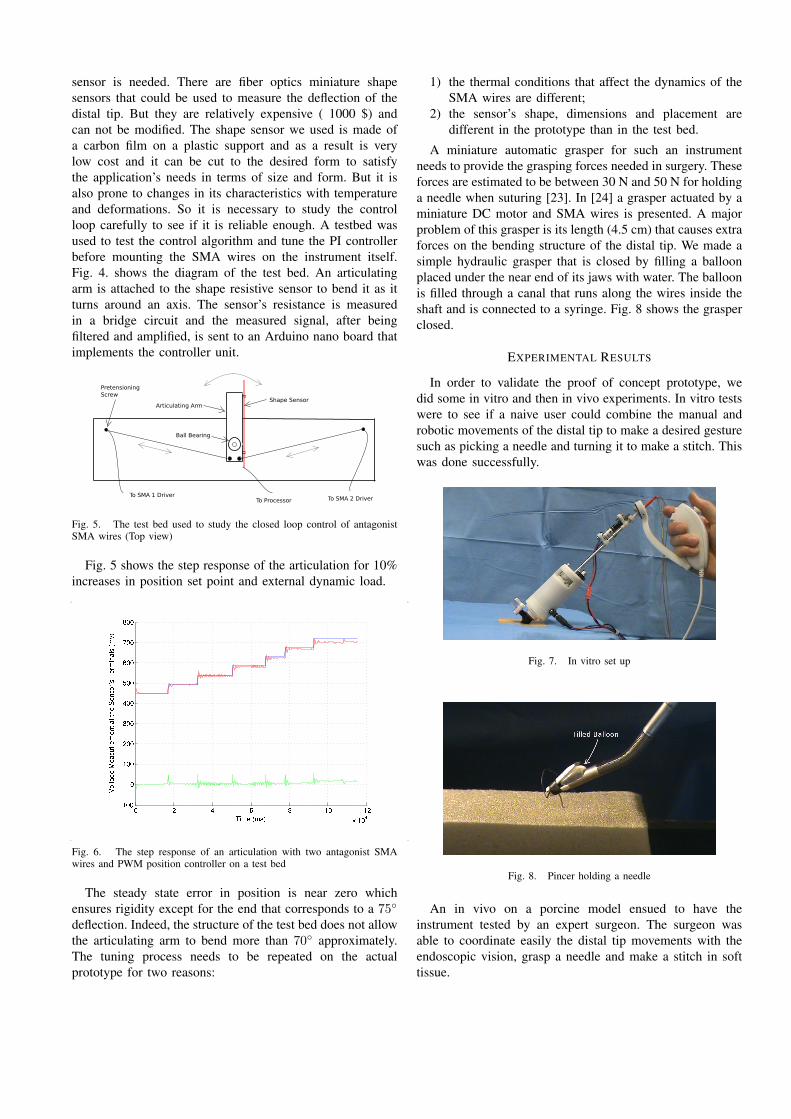
sensor is needed. There are fiber optics miniature shapesensors that could be used to measure the deflection of thedistal tip. But they are relatively expensive ( 1000 $) andcan not be modified. The shape sensor we used is made ofa carbon film on a plastic support and as a result is verylow cost and it can be cut to the desired form to satisfythe application’s needs in terms of size and form. But it isalso prone to changes in its characteristics with temperatureand deformations. So it is necessary to study the controlloop carefully to see if it is reliable enough. A testbed wasused to test the control algorithm and tune the PI controllerbefore mounting the SMA wires on the instrument itself.Fig. 4. shows the diagram of the test bed. An articulatingarm is attached to the shape resistive sensor to bend it as itturns around an axis. The sensor’s resistance is measuredin a bridge circuit and the measured signal, after beingfiltered and amplified, is sent to an Arduino nano board thatimplements the controller unit.
To SMA 1 DriverTo SMA 2 DriverTo Processor
Shape SensorArticulating Arm
Ball Bearing
PretensioningScrew
Fig. 5. The test bed used to study the closed loop control of antagonistSMA wires (Top view)
Fig. 5 shows the step response of the articulation for 10%increases in position set point and external dynamic load.
Fig. 6. The step response of an articulation with two antagonist SMAwires and PWM position controller on a test bed
The steady state error in position is near zero whichensures rigidity except for the end that corresponds to a 75◦
deflection. Indeed, the structure of the test bed does not allowthe articulating arm to bend more than 70◦ approximately.The tuning process needs to be repeated on the actualprototype for two reasons:
1) the thermal conditions that affect the dynamics of theSMA wires are different;
2) the sensor’s shape, dimensions and placement aredifferent in the prototype than in the test bed.
A miniature automatic grasper for such an instrumentneeds to provide the grasping forces needed in surgery. Theseforces are estimated to be between 30 N and 50 N for holdinga needle when suturing [23]. In [24] a grasper actuated by aminiature DC motor and SMA wires is presented. A majorproblem of this grasper is its length (4.5 cm) that causes extraforces on the bending structure of the distal tip. We made asimple hydraulic grasper that is closed by filling a balloonplaced under the near end of its jaws with water. The balloonis filled through a canal that runs along the wires inside theshaft and is connected to a syringe. Fig. 8 shows the grasperclosed.
EXPERIMENTAL RESULTS
In order to validate the proof of concept prototype, wedid some in vitro and then in vivo experiments. In vitro testswere to see if a naive user could combine the manual androbotic movements of the distal tip to make a desired gesturesuch as picking a needle and turning it to make a stitch. Thiswas done successfully.
Fig. 7. In vitro set up
Fig. 8. Pincer holding a needle
An in vivo on a porcine model ensued to have theinstrument tested by an expert surgeon. The surgeon wasable to coordinate easily the distal tip movements with theendoscopic vision, grasp a needle and make a stitch in softtissue.

Fig. 9. In vivo set up
Fig. 10. Pincer holding a needle
CONCLUSION
The problem of making a dexterous, intuitive and er-gonomic instrument for laparoscopy is the focus of ourresearch. Making such an instrument needs a global studyof these problems. The research conducted in this directionshas provided some solutions, but technological realizationof these solutions has not resulted in a satisfactory outcomeyet. We developed the concepts of active trocar and free-orientation-handle as answers to some of the shortcomingsof the previous efforts.
The prototype instrument developed based on these con-cepts was tested in vitro and in vivo to make surgicalgestures. The new handle helps reduce the burdeon onthe surgeon’s arm, while the active trocar simplifies themechanical transmission system and maintains the rigidityof the end-effector. The hydraulic grasper proves to be aneffective solution to the problem of designing an automaticminiature grasper.
To make the future instrument more intuitive and shortenits learning curve, the design of the handle, its controllingelements and how each of them is coupled to the distal tip’sDOF must be studied in .
REFERENCES
[1] P. Yohannes, P. Rotariu, P. Pinto, A. D. Smith, and B. R. Lee,“Comparison of robotic versus laparoscopic skills: is there a differencein the learning curve?,” Urology, vol. 60, July 2002.
[2] G. Guthart and J. J. Salisbury, “The intuitive telesurgery system:overview and application,” Proceedings of ICRA ’00, vol. 1, pp. 618–621 vol.1, 2000.
[3] C. D. Hinman and D. J. Danitz, “Tool with rotation lock,” UnitedStates Patent Application # US 2007/0287993 A1, Dec. 2007.
[4] W. Lee and A. Chamorro, “Surgical instrument,” United States Patent# US 7615067 B2, Cambridge Endoscopic Devices, Inc., Framingham,MA (US), Nov. 2009.
[5] K. M. Schwarz, M. O. Schurr, and G. F. Buesz, “Surgical instrumentfor minimally invasive surgical interventions,” United States Patent# US 6,913,613 B2, Tuebingen Scientific Surgical Products GmbH,Tuebingen (DE), July 2005.
[6] S. Marczyk, “Surgical instrument with articulating tool assembly,”United States Patent Application # US 2008/0083811 A1, Apr. 2008.
[7] M. Piccigallo, F. Focacci, O. Tonet, G. Megali, C. Quaglia, andP. Dario, “Hand-held robotic instrument for dextrous laparoscopicinterventions.,” The international journal of medical robotics + com-puter assisted surgery : MRCAS, vol. 4, pp. 331–338, December 2008.
[8] D. Gossot and G. Lange, “Deflectable and rotatable endoscopic in-strument with intuitive control,” Minimally Invasive Therapy & AlliedTechnologies, vol. 10, pp. 295–299, November 2001.
[9] G. J. M. Tuijthof, S. J. M. P. van Engelen, J. L. Herder, R. H. M.Goossens, C. J. Snijders, and C. N. van Dijk, “Ergonomic handlefor an arthroscopic cutter,” Minimally Invasive Therapy & AlliedTechnologies, vol. 12, pp. 82–90, January 2003.
[10] A. Melzer, K. Kipfmuller, and B. Halfar, “Deflectable endoscopicinstrument system DENIS,” Surgical Endoscopy, vol. 11, pp. 1045–1051, 1997. 10.1007/s004649900523.
[11] M. S. Hallbeck, D. Oleynikov, K. Done, T. Judkins, A. DiMartino,J. Morse, and L. N. Verner, “Ergonomic handle and articulating la-paroscopic tool,” United States Patent Application # US 2005/0187575A1, Aug. 2005.
[12] M. Jinno, T. Sunaoshi, and S. Omori, “Manipulator and control methodtherefor,” United States Patent Application # US 2008/0245175 A1,Terumo Kabushiki Kaisha, Tokyo (JP) and Kabushiki Kaisha Toshiba,Tokyo (JP), Oct. 2008.
[13] H. Yamashita, A. Iimura, E. Aoki, T. Suzuki, T. Nakazawa,E. Kobayashi, M. Hashizume, I. Sakuma, and T. Dohi, “Develeopmentof endoscopic forceps manipulator using multi-slider linkage mecha-nisms,” Proceeding of The 1st Asian Symposium on Computer AidedSurgery - Robotic and Image guided Surgery, Apr. 2005.
[14] A. Hassan Zahraee, J. Szewczyk, and G. Morel, “Evaluating controlmodes for hand-held robotic surgical instrument using virtual realitysimulator,” pp. 1946–1951, July 2009.
[15] A. Hassan Zahraee, J. K. Paik, J. Szewczyk, and G. Morel, “Robotichand-held surgical device evaluation of end-effectors kinematics anddeveloppement of proof-of-concept prototypes,” Proceedings of MIC-CAI ’10, Sept. 2010.
[16] R. Berguer, S. Gerber, G. Kilpatrick, and D. Beckley, “An ergonomiccomparison of in-line vs pistol-grip handle configuration in a laparo-scopic grasper,” Surgical Endoscopy, vol. 12, pp. 805–808, 1998.10.1007/s004649900717.
[17] U. Matern and P. Waller, “Instruments for minimally invasive surgery:principles of ergonomic handles,” Surgical Endoscopy, vol. 13,pp. 174–182, 1999. 10.1007/s004649900934.
[18] U. Matern, M. Eichenlaub, P. Waller, and K. D. Ruckauer, “MISinstruments. an experimental comparison of various ergonomic handlesand their design,” Surgical Endoscopy, vol. 13, pp. 756–762, 1999.10.1007/s004649901093.
[19] M. A. Veelen, D. W. Meijer, R. H. Goossens, C. J. Snijders, and J. J.Jakimowicz, “Improved usability of a new handle design for laparo-scopic dissection forceps,” Surgical Endoscopy, vol. 16, pp. 201–207,2002. 10.1007/s004640090102.
[20] S. Ahmed, G. Hanna, and A. Cuschieri, “Optimal angle betweeninstrument shaft and handle for laparoscopic bowel suturing,” Archivesof Surgery, vol. 139, Jan. 2004.
[21] Q. Mexico and T. Hino, “Development of a miniature robot finger witha variable stiffness mechanism using shape memory,” InternationalSimposium on Robotics and Automation, Aug. 2004.
[22] N. Ma and G. SONG, “Control of shape memory alloy actuator usingpulse width modulation,” Smart materials and structures, vol. 12,no. 5, pp. 712–719, 2003.
[23] J. Rosen, J. D. Brown, M. Barreca, L. Chang, B. Hannaford, andB. Sinanan, “The blue dragon - a system for monitoring the kinematicsand the dynamics of endoscopic tools in minimally invasive surgery forobjective laparoscopic skill assessment,” vol. 85, pp. 412–418, 2002.
[24] V. Kode and M. Cavusoglu, “Design and characterization of a novelhybrid actuator using shape memory alloy and dc micromotor forminimally invasive surgery applications,” Mechatronics, IEEE/ASMETransactions on, vol. 12, pp. 455–464, Aug. 2007.