mechatronics engineering department hashemite · pdf fileplc exercises ladder diagram...
TRANSCRIPT

PLC Exercises Ladder Diagram Programming
By
Dr. Mohammad SalahMechatronics Engineering Department
Hashemite University

٢
Dr. Mohammad Salah – Mechatronics
Steps for Building a Ladder Diagram
1.
Determine the No. of digital I/O2.
Determine the No. of analog I/O (if needed)
3.
Determine if there are special functions in the process4.
Estimate program capacity depending on the process
5.
Choose a suitable PLC series6.
Prepare the wiring diagram
7.
Draw flowchart or control diagram (Optional)8.
Program the PLC using the ladder diagram
٣
Dr. Mohammad Salah – Mechatronics
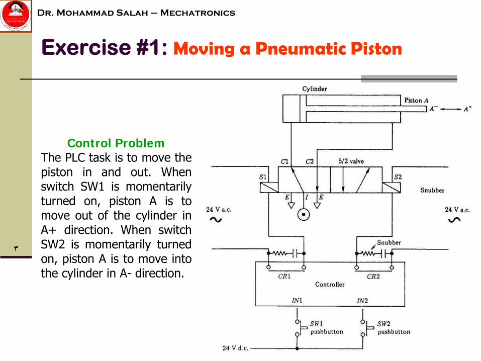
Exercise #1:
Moving a Pneumatic Piston
Control ProblemThe PLC task is to move the piston in and out. When switch SW1 is momentarily turned on, piston A is to
move out of the cylinder in A+ direction. When switch SW2 is momentarily turned on, piston A is to move into the cylinder in A-
direction.

٤
Dr. Mohammad Salah – Mechatronics
Exercise #1:
Moving a Pneumatic Piston

٥
Dr. Mohammad Salah – Mechatronics
Exercise #1:
Moving a Pneumatic Piston
The two solenoid valves will be tuned off
If SW1 and SW2 are pressed together, what would happen?
Use the contacts of the main relays instead of the input contacts
How can we make an electrical interlock?

٦
Dr. Mohammad Salah – Mechatronics
Exercise #2:
Sequencing of Pneumatic Pistons
Control ProblemThe PLC task is to operate piston A followed by
piston B followed by piston C. The sequence is A+, A-, B+, B-, C+, C-
is to be repeated when switch
SW1 is turned on

٧
Dr. Mohammad Salah – Mechatronics
Exercise #2:
Sequencing of Pneumatic Pistons

٨
Dr. Mohammad Salah – Mechatronics
Exercise #2:
Sequencing of Pneumatic Pistons
•
Solenoid valves do not work•
The wiring of solenoid valves is not correct or not in the correct order (wiring problem)
•
The ladder diagram is not properly written (sequence in not correct)
If the system does not work or sequence in not correct, what would be the possible reasons?

٩
Dr. Mohammad Salah – Mechatronics
Exercise #3:
Batching Machine
Control ProblemThe PLC task is to control a simple machine which counts and batches components moving along a conveyor. It is required that ten components be channeled down route A and twenty components down route B. A reset facility is required

١٠
Dr. Mohammad Salah – Mechatronics
Exercise #3:
Batching Machine

١١
Dr. Mohammad Salah – Mechatronics
Exercise #3:
Batching Machine

١٢
Dr. Mohammad Salah – Mechatronics
Exercise #3:
Batching Machine
•
The reset switch is always on•
The microswitch does not work
•
The flap solenoid does not work•
The ladder diagram is not properly written
If the system does not batch and/or count, what would be the possible reasons?

١٣
Dr. Mohammad Salah – Mechatronics
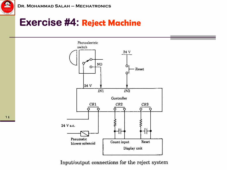
Exercise #4:
Reject Machine
Control ProblemThe PLC task is to detect and reject faulty components. Components are transported on a conveyor past a retro-reflective type photoelectric switch. The photoelectric switch is positioned at a height (H) above the conveyor where (H) represents a tolerance value for component height. Good components pass underneath the photoelectric switch and no signal is generated. Faulty
components break the light beam twice as they pass the photoelectric switch.
١٤
Dr. Mohammad Salah – Mechatronics
Exercise #4:
Reject Machine

١٥
Dr. Mohammad Salah – Mechatronics
Exercise #4:
Reject Machine

١٦
Dr. Mohammad Salah – Mechatronics
Exercise #4:
Reject Machine
•
The photoelectric switch is too high (H is too big)•
The photoelectric switch does not work
•
The pneumatic blower does not work•
The ladder diagram is not properly written
•
The faulty components is not as described in the drawing
If the system does not reject faulty components, what would be the possible reasons?

١٧
Dr. Mohammad Salah – Mechatronics
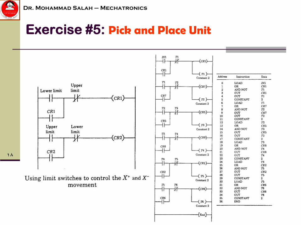
Exercise #5:
Pick and Place Unit
Control ProblemThe PLC task is to:a)
move the gripper to X+ position
b)
close the gripper so that it takes hold of a componentc)
rotate the gripper through 180o
to the Θ+ positiond)
Release the component
e)
Rotate the gripper back to the Θ-
position so that the pick and place operation may be repeated
١٨
Dr. Mohammad Salah – Mechatronics
Exercise #5:
Pick and Place Unit

١٩
Dr. Mohammad Salah – Mechatronics
Exercise #5:
Pick and Place Unit
•
Wiring problem•
Some solenoid valves do not work
•
Timing is not correct•
The ladder diagram is not properly written (sequence in not correct)
If the system does not work or sequence is not correct, what would be the possible reasons?
Use position sensors for feedback but that would be expensive compared to using timers but more accurate and reliable in case the mechanical system starts to have some problems
How can we get rid of the timers in the ladder diagram/program?

٢٠
Dr. Mohammad Salah – Mechatronics
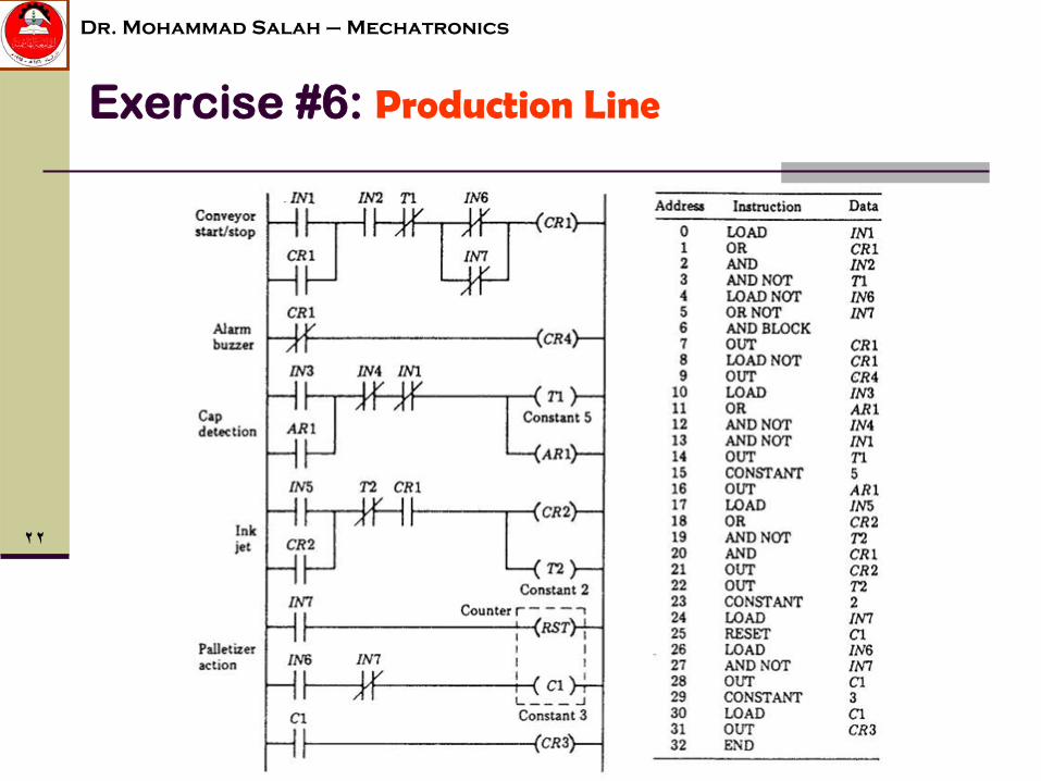
Exercise #6:
Production Line
Control ProblemThe PLC task is to organize the production process. Cans filled with fluid and capped before passing into a conveyor. The photoelectric switches P1 and P2 are used to check that each can has a cap. Photoelectric switch P3 provides a trigger for the ink jet printer which prints a batch number on each can.
Photoelectric
switch P4 is used to count three cans into the palletizing machine that transports three cans through a machine which heat shrinks a plastic wrapping over them. All photoelectric switches on the production line are of the retro reflective type.

٢١
Dr. Mohammad Salah – Mechatronics
Exercise #6:
Production Line
٢٢
Dr. Mohammad Salah – Mechatronics
Exercise #6:
Production Line
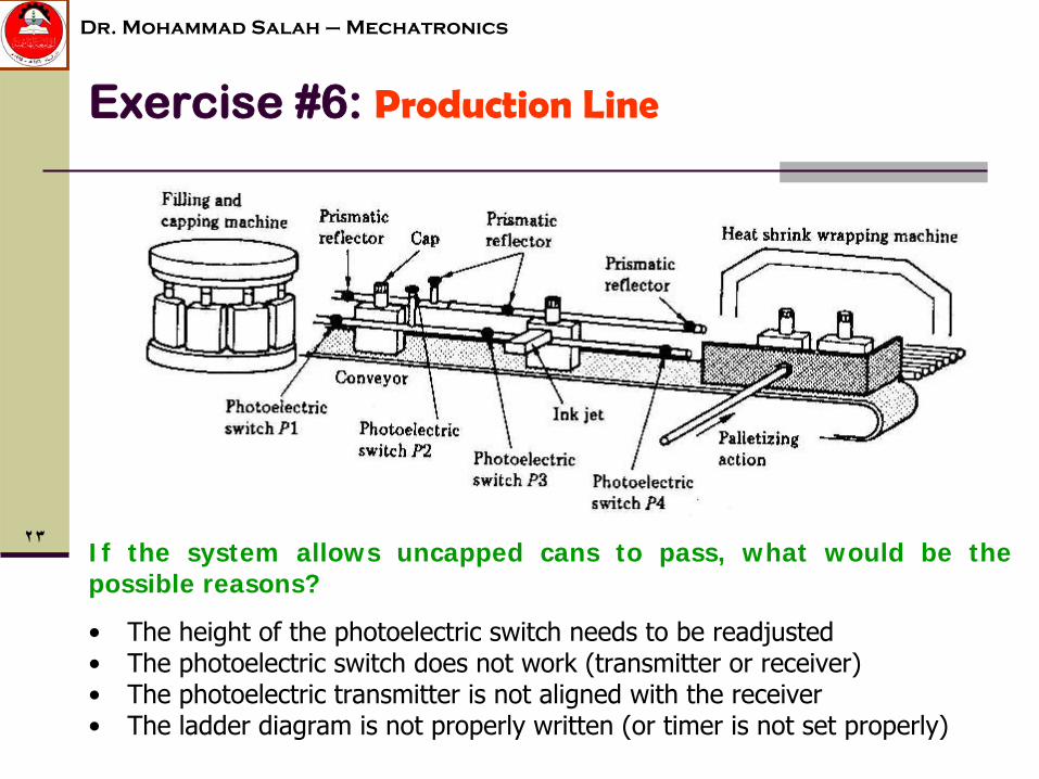
٢٣
Dr. Mohammad Salah – Mechatronics
Exercise #6:
Production Line
•
The height of the photoelectric switch needs to be readjusted•
The photoelectric switch does not work (transmitter or receiver)
•
The photoelectric transmitter is not aligned with the receiver•
The ladder diagram is not properly written (or timer is not set properly)
If the system allows uncapped cans to pass, what would be the possible reasons?

٢٤
Dr. Mohammad Salah – Mechatronics
Exercise #7:
Star-Delta Connection

٢٥
Dr. Mohammad Salah – Mechatronics
Exercise #7:
Star-Delta Connection

٢٦
Dr. Mohammad Salah – Mechatronics
Exercise #7:
Star-Delta Connection
PLC system layout – Wiring diagram

٢٧
Dr. Mohammad Salah – Mechatronics
Exercise #7:
Star-Delta Connection