mechatronics...introduction to the plc ladder diagram series and series-parallel control circuits...
TRANSCRIPT
Mechatronics Training Lab
M
ECH
ATR
ON
ICS
About SES
An Edtech industry leader and innovator, SES Scientific Educational Systems, goes above and beyond to supply educators and learners with the best educational systems, including Neulog, Degem Systems, MultiCenter and MagiClass. Renowned for their ability to cater to numerous fields, sectors and segments, SES systems spread across a wide spectrum, offering unique solutions in the fields of electronics, microcontrollers, telecommunication, autotronics, mechatronics, pneumatics, hydraulics, CNC machines, refrigeration and air-conditioning, green energy, computerized systems, science, robotics, logger sensors and STEM. Each proprietary SES system and device is perfectly designed and manufactured from the highest quality materials in accordance with all safety requirements and regulations. SES is a quality assured firm with the certification of ISO-9001:2015. SES solutions are used in over 50 countries worldwide by professional developers for high-level technological commercial products and both governmental and private institutions covering educational programs for universities, colleges, vocational training centers and schools, high schools, junior high schools and primary schools.

1 Mechatronics V4_4
Mechatronics training program
Mechanical systems turn into electronic embedded systems. Electronics, microcontrollers and programmable logic controllers (PLC) are the basis of sensors, control and driving systems. Mechanical systems use electric motors, sensors, electronic actuators. The mechanic profession requires knowledge in electronics and controllers. Knowledge of mechanical elements such as pneumatic systems, hydraulic systems, transmissions, levers and so on is still needed. Robotics is a very important discipline of mechatronics. Robotics is the discipline that combines electricity, electronics, sensors, mechanics and coding units. The mechatronics program includes the following disciplines: Basic electronics Pneumatics systems Hydraulics systems CNC machines

2 Mechatronics V4_4
Electronics with EB-3000 universal trainer
EB-3000 supports every stage of electronics study, which is a must for almost every
profession in: electronics, electricity, mechatronics, automotive, instrumentation, process control, etc.
The system includes: 5-voltages power supply, 2 voltmeters, ammeter, frequency
counter, logic probe, logic analyzer, 2-channel digital oscilloscope, function generator (sine, triangle and square signals).
The system contains also: 3.2" color graphic display with touch panel, keyboard, 10
relays for inserting faults. The system provides USB wire communication with the PC for:
Virtual instrument D-Scope software that controls the system function generator and graphic display of the scope signals.
Microprocessor and microcontroller editor, assembler, C compiler and debugger development software.
The plug-in cards are connected to the trainer through a 48-contact, very low
resistance industrial connector. Each plug-in card has its own controller for automatic identification by the main
platform, for saving its required configuration and for automatic self-diagnostics while plugging it in.
Experiment manual and courseware (including theory) for every card. Various electronics study programs for Mechatronics, for Autotronics, for Electrical
Machines and Electricity using EB-3000 and its plug-in experiment cards are available.

3 Mechatronics V4_4
Electronics topics for Mechatronics
Direct current, Ohm's Law and electrical power Kirchhoff's laws and electric circuits Resistors and potentiometers Semiconductorד – diodes, LEDs, Transistors Magnetism, Alternate current Transformers, motors and generators Capacitors and inductors Electronic systems Sensors and actuators Converters (ADC, DAC) Microcontroller programming
EB-3000 Basic electronics cards
Electricity and Electrical Circuits EB-3121 Ohm and Kirchhoff Laws and DC circuits EB-3122 Norton, Thevenin and superposition EB-3123 AC circuits, signals and filters EB-3124 Magnetism, electromagnetism, induction and transformers Semiconductor Devices EB-3125 Diodes, Zener, bipolar and FET transistors characteristics and
DC circuits EB-3126 Bipolar and FET transistor amplifiers EB-3127 Industrial semiconductors – SCR, Triac, Diac and PUT EB-3128 Optoelectronic semiconductors – LED, phototransistor, LDR, 7-SEG Motors, Generators and Inverters EB-3141 Analog, PWM DC motor speed control, step motor control, generators EB-3142 Motor control – optical, Hall Effect, motor closed control EB-3143 AC-DC and DC-AC conversion circuits EB-3144 3 Phase motor control Digital Electronics EB-3151 AND, OR, NOT, NAND, NOR, XOR logic components & Boolean algebra EB-3152 Decoders, multiplexers and adders EB-3153 Flip-flops, registers, and counters sequential logic circuits EB-3154 555, ADC, DAC circuits Microprocessor/Microcontroller Technology EB-3191 Introduction to microprocessors and microcontrollers The document 'Electronics Training Labs' describes the specifications of the EB-3000 universal training system and the EB-3000 electronics cards.

4 Mechatronics V4_4
Pneumatics topics
Basic pneumatics
Manually operated valves Single and double acting cylinders Air-spring, air-air and double pilot valves Control circuit with air spring and check valve Flow control and speed regulation methods Semi-automatic and automatic control systems Integrated sensor control Time delay pneumatic circuits and components Operation of two cylinders in parallel
Advance pneumatics and logic
Air sliding principle Air motor Venturi principle Pneumatic manipulator Logic OR, AND, NOT, NOR, NAND gates Pneumatic timer in a heat sealing application Logic memory Trigger control circuit with a T flip-flop Clamping and drill control circuit Cascade circuits Sliding table and drilling system
Basic electro-pneumatics
Series and parallel electrical circuits Electromagnet and its applications Series and parallel control for a double acting cylinder Semi-automatic actuator circuit Reed switch as a contact multiplier Use of a relay in an electrical control circuit Self-holding relay in an emergency stop circuit Automatic control using a relay memory On-delay and off-delay timer circuits Safety operation circuits

5 Mechatronics V4_4
Advance electro-pneumatics
Hall Effect sensor Optical, capacitive and inductive proximity sensors Control circuit with two spring return solenoid valves Logic and electrical cascade circuits Sequence control and timing circuits Cascade electronic counter design Stepper motor and control circuit
Programmable logic controller (PLC)
Introduction to the PLC ladder diagram Series and series-parallel control circuits Use of internal PLC coil, self-hold and break priority Relay memory, programming a sequence On delay and off delay timers and control circuits Three piston cascade counter circuits Design and programming exercises for applications:

6 Mechatronics V4_4
Pneumatics equipment
PN-3401 – Pneumatics Master Board
4 rack units 2 pressure gauges 3 pneumatics taps Air resevoir regulator Power switch and power supply 12V outlets
PN-3410 – basic pneumatics including:
PN-3411 – Basic Pneumatics I Flow meter 20-200 SCFH Flow control with check valve Check valve Manual valve, 3/2 way with spring returned pushbutton 5/2 way spring returned piloted valve
PN-3412 – Basic Pneumatics II Double acting cylinder 20x100 mm Double acting cylinder 12x50 mm Directional 5/3 way position valve, closed center Reservoir
PN-3413 – Basic Pneumatics III Manual valve, 3/2 -way spring returned with mushroom pushbutton 5/2 way double piloted valve (2 each) Manual valve 3/2 way with push-button
PN-3414 – Basic Pneumatics IV Roller lever valve, 3/2 way (4 each) One way trip operated spring returned valve, 3/2 way Spring returned cylinder 12x50 mm
PN-3420 – advanced pneumatics & logic including:
PN-3421 – Advanced Pneumatics & Logic I Inclined-vertical water column pressure gauge Transparent Venturi tube block Vacuum actuator / suction block
PN-3422 – Advanced Pneumatics & Logic II Air motor Load and torque measuring device Transparent air bearing
PN-3423 – Advanced Pneumatics & Logic III Pneumatic time delay valve Pneumatic signal indicators (2) Quick exhaust valve
PN-3424 – Advanced Pneumatics & Logic IV AND elements (2) OR elements (2) NOT element Memory elements (2)
7 Mechatronics V4_4
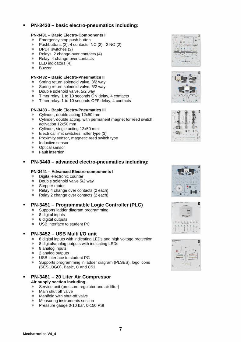
PN-3430 – basic electro-pneumatics including:
PN-3431 – Basic Electro-Components I Emergency stop push button Pushbuttons (2), 4 contacts: NC (2), 2 NO (2) DPDT switches (2) Relays, 2 change-over contacts (4) Relay, 4 change-over contacts LED indicators (4) Buzzer
PN-3432 – Basic Electro-Pneumatics II Spring return solenoid valve, 3/2 way Spring return solenoid valve, 5/2 way Double solenoid valve, 5/2 way Timer relay, 1 to 10 seconds ON delay, 4 contacts Timer relay, 1 to 10 seconds OFF delay, 4 contacts
PN-3433 – Basic Electro-Pneumatics III Cylinder, double acting 12x50 mm Cylinder, double acting, with permanent magnet for reed switch
activation 12x50 mm Cylinder, single acting 12x50 mm Electrical limit switches, roller type (3) Proximity sensor, magnetic reed switch type Inductive sensor Optical sensor Fault insertion
PN-3440 – advanced electro-pneumatics including:
PN-3441 – Advanced Electro-components I Digital electronic counter Double solenoid valve 5/2 way Stepper motor Relay 4 change over contacts (2 each) Relay 2 change over contacts (2 each)
PN-3451 – Programmable Logic Controller (PLC)
Supports ladder diagram programming 8 digital inputs 6 digital outputs USB interface to student PC
PN-3452 – USB Multi I/O unit
8 digital inputs with indicating LEDs and high voltage protection 8 digital/analog outputs with indicating LEDs 8 analog inputs 2 analog outputs USB interface to student PC Supports programming in ladder diagram (PLSES), logo icons
(SESLOGO), Basic, C and C51 PN-3481 – 20 Liter Air Compressor
Air supply section including: Service unit (pressure regulator and air filter) Main shut off valve Manifold with shut-off valve Measuring instruments section Pressure gauge 0-10 bar, 0-150 PSI

8 Mechatronics V4_4
Hydraulics topics
Basic hydraulics
Familiarization with the hydraulic power unit and main platform Installation and maintenance of the power unit and main platform Relation between flow rate and pressure Adjustable pressure relief valve to limit pressure Compensated flow control valves Non-return and pilot check valves Double acting cylinder in two-way movement application
Advanced hydraulics
Operation of a differential cylinder Two speed cylinder system Pilot pressure adjustable relief valve Two speed piston stroke Hydraulic motor and control circuit Hydraulic accumulator Testing and adjusting pressure control valves and cylinders Designing a simple hydraulic system
Basic electro-hydraulics
Series and parallel control Use of a relay in an electrical control circuit The relay as a memory device with self-holding and break priority Push button switch, limit switch and pressure switch applications Self-holding relay as a memory device Automatic actuator circuit
Advanced electro-hydraulics
On-delay and off-delay timer control circuits Optical, capacitive and inductive sensors Safety operation circuit Semi-automatic drill system Control circuit with electronic counter Electro-hydraulic control circuit Electro-hydraulic control circuit with a counter

9 Mechatronics V4_4
Programmable logic controller (PLC)
Introduction to the PLC ladder diagram Series and series-parallel control circuits Use of internal PLC coil, self-hold and break priority Relay memory, programming a sequence On delay and off delay timers and control circuits Three piston cascade counter circuits Design and programming exercises for applications
10 Mechatronics V4_4
Hydraulics equipment
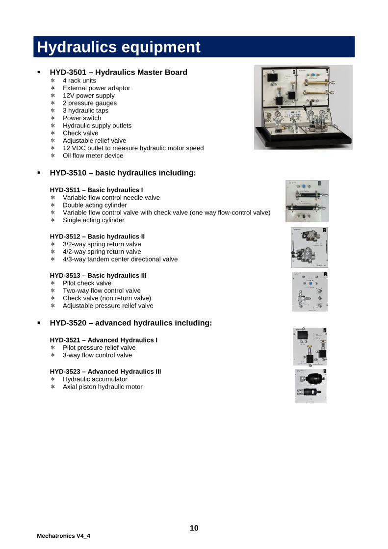
HYD-3501 – Hydraulics Master Board
4 rack units External power adaptor 12V power supply 2 pressure gauges 3 hydraulic taps Power switch Hydraulic supply outlets Check valve Adjustable relief valve 12 VDC outlet to measure hydraulic motor speed Oil flow meter device
HYD-3510 – basic hydraulics including:
HYD-3511 – Basic hydraulics I Variable flow control needle valve Double acting cylinder Variable flow control valve with check valve (one way flow-control valve) Single acting cylinder
HYD-3512 – Basic hydraulics II 3/2-way spring return valve 4/2-way spring return valve 4/3-way tandem center directional valve
HYD-3513 – Basic hydraulics III Pilot check valve Two-way flow control valve Check valve (non return valve) Adjustable pressure relief valve
HYD-3520 – advanced hydraulics including:
HYD-3521 – Advanced Hydraulics I Pilot pressure relief valve 3-way flow control valve
HYD-3523 – Advanced Hydraulics III Hydraulic accumulator Axial piston hydraulic motor

11 Mechatronics V4_4
HYD-3530 – basic electro-hydraulics including:
PN-3431 – Basic Electro-Components I Emergency stop push button Pushbuttons (2), 4 contacts: NC (2), 2 NO (2) DPDT switches (2) Relays, 2 change-over contacts (4) Relay, 4 change-over contacts LED indicators (4) Buzzer
HYD-3532– Basic Electro-hydraulics II 4/3-way double pilot valve (closed center) 3/2-way spring return solenoid valve
HYD-3534– Basic Electro-hydraulics IV 4/2-way valve solenoid - solenoid
HYD-3540 – advanced electro-hydraulics including:
HYD-3541 – Advanced Electro-components I Digital electronic counter Stepper motor Relay 4 change over contacts (2 each) Relay 2 change over contacts (2 each)
PN-3451 – Programmable Logic Controller (PLC)
Supports ladder diagram programming 8 digital inputs 6 digital outputs USB interface to student PC
PN-3452 – USB Multi I/O unit
8 digital inputs with indicating LEDs and high voltage protection 8 digital/analog outputs with indicating LEDs 8 analog inputs 2 analog outputs USB interface to student PC Supports programming in ladder diagram (PLSES), logo icons
(SESLOGO), Basic, C and C51

12 Mechatronics V4_4
CNC machines topics
CNC Lathe machine topics
This course introduces students to the CNC lathe machine. The students are exposed to industrial processes and control. The objectives of the course include teaching the students how to operate the lathe, and how to apply the program instructions in a logical sequence to produce a product.
System description G-code and M-code Installing the LATHE software Operating the system Monitor description Turning processing Arches Turning the rod Project processing CAD-CAM design and processing (optional)
CNC Milling machine topics
This course introduces students to the CNC Milling machine. The students are exposed to industrial processes and control. The objectives of the course include teaching the students how to operate the lathe, and how to apply the program instructions in a logical sequence to produce a product.
System description G code and M code Operating the MILL software Operating the entire system Monitor description Slot processing Arches Profile processing Pocket processing Drill processing Project processing CAD-CAM design and processing (optional)
13 Mechatronics V4_4
CNC Equipment
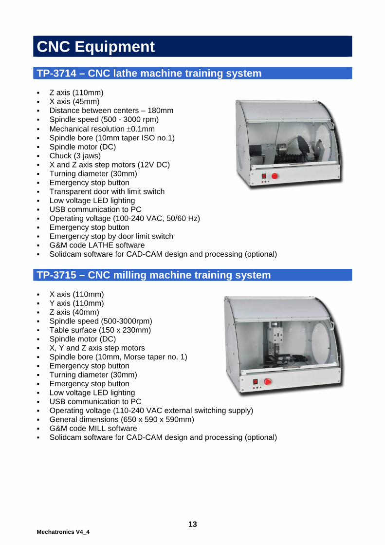
TP-3714 – CNC lathe machine training system Z axis (110mm) X axis (45mm) Distance between centers – 180mm Spindle speed (500 - 3000 rpm) Mechanical resolution ±0.1mm Spindle bore (10mm taper ISO no.1) Spindle motor (DC) Chuck (3 jaws) X and Z axis step motors (12V DC) Turning diameter (30mm) Emergency stop button Transparent door with limit switch Low voltage LED lighting USB communication to PC Operating voltage (100-240 VAC, 50/60 Hz) Emergency stop button Emergency stop by door limit switch G&M code LATHE software Solidcam software for CAD-CAM design and processing (optional) TP-3715 – CNC milling machine training system X axis (110mm) Y axis (110mm) Z axis (40mm) Spindle speed (500-3000rpm) Table surface (150 x 230mm) Spindle motor (DC) X, Y and Z axis step motors Spindle bore (10mm, Morse taper no. 1) Emergency stop button Turning diameter (30mm) Emergency stop button Low voltage LED lighting USB communication to PC Operating voltage (110-240 VAC external switching supply) General dimensions (650 x 590 x 590mm) G&M code MILL software Solidcam software for CAD-CAM design and processing (optional)

14 Mechatronics V4_4
PN-3400 Pneumatics trainer specifications
The PN-3400 Pneumatics Trainer, basic unit comprises a compact desktop universal master board (PN-3401), four sets of industrial pneumatics (PN-3410, 3420, 3430, 3440) component boards and comprehensive theory and practice manuals. PN-3401 – Pneumatics master board Size (W x H x D): 575 x 490 x 455 mm 4 rack units 12V power supply 2 pressure gauges 3 pneumatics taps Air reservoir regulator Power switch Power supply 12V outlets External power adaptor
PN-3481 – Air compressor Air supply section including: Service unit (pressure regulator and air filter) Main shut off valve Manifold with shut-off valve Pressure gauge 0-12 bar, 0-180 PSI 0.75 HP (0.55 KW) Operating pressure 8 bar 110 L/Min 10 m 8 mm hose
15 Mechatronics V4_4
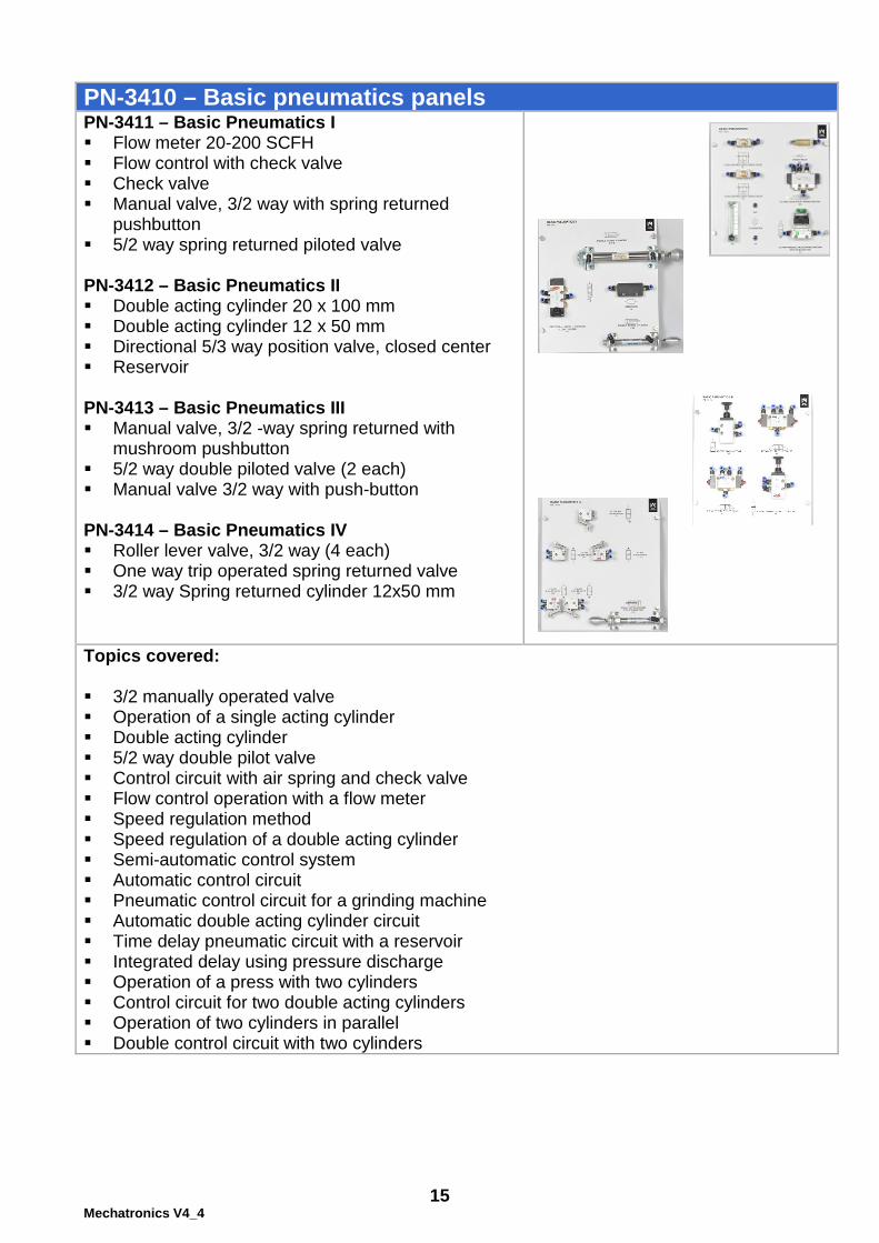
PN-3410 – Basic pneumatics panels PN-3411 – Basic Pneumatics I Flow meter 20-200 SCFH Flow control with check valve Check valve Manual valve, 3/2 way with spring returned
pushbutton 5/2 way spring returned piloted valve PN-3412 – Basic Pneumatics II Double acting cylinder 20 x 100 mm Double acting cylinder 12 x 50 mm Directional 5/3 way position valve, closed center Reservoir PN-3413 – Basic Pneumatics III Manual valve, 3/2 -way spring returned with
mushroom pushbutton 5/2 way double piloted valve (2 each) Manual valve 3/2 way with push-button PN-3414 – Basic Pneumatics IV Roller lever valve, 3/2 way (4 each) One way trip operated spring returned valve 3/2 way Spring returned cylinder 12x50 mm
Topics covered: 3/2 manually operated valve Operation of a single acting cylinder Double acting cylinder 5/2 way double pilot valve Control circuit with air spring and check valve Flow control operation with a flow meter Speed regulation method Speed regulation of a double acting cylinder Semi-automatic control system Automatic control circuit Pneumatic control circuit for a grinding machine Automatic double acting cylinder circuit Time delay pneumatic circuit with a reservoir Integrated delay using pressure discharge Operation of a press with two cylinders Control circuit for two double acting cylinders Operation of two cylinders in parallel Double control circuit with two cylinders

16 Mechatronics V4_4
PN-3420 – Advanced pneumatics & logic panels PN-3421 – Advanced Pneumatics & Logic I Inclined-vertical water column pressure gauge Transparent Venturi tube block Vacuum actuator/suction block PN-3422 – Advanced Pneumatics & Logic II Air motor Load and torque measuring device Transparent air bearing PN-3423 – Advanced Pneumatics & Logic III Pneumatic time delay valve Pneumatic signal indicators (2) Quick exhaust valve PN-3424 – Advanced Pneumatics & Logic IV AND elements (2) OR elements (2) NOT element Memory elements (2)
Topics covered: Pneumatic control of a punch machine Air sliding principle Air motor Venturi principle Pneumatic manipulator Logic OR gate Pneumatic timer in a heat sealing application AND gate "Two hands on" safety control NOT gate NOR gate NAND gate Logic memory Trigger control circuit with a T flip-flop Clamping and drill control circuit Cascade circuit Sliding table and drilling system

17 Mechatronics V4_4
PN-3430 – Basic electro-pneumatics including PN-3431 – Basic Electro-Components I Emergency stop push button Pushbuttons (2), 4 contacts: NC (2), 2 NO (2) DPDT switches (2) Relays, 2 change-over contacts (4) Relay, 4 change-over contacts LED indicators (4) Buzzer PN-3432 – Basic Electro-Pneumatics II Spring return solenoid valve, 3/2 way Spring return solenoid valve, 5/2 way Double solenoid valve, 5/2 way Timer relay, 1 to 10 seconds ON delay, 4 contacts Timer relay, 1 to 10 seconds OFF delay, 4 contacts PN-3433 – Basic Electro-Pneumatics III Cylinder, double acting 12x50 mm Cylinder, double acting, with permanent magnet for reed
switch activation 12x50 mm Cylinder, single acting 12x50 mm Electrical limit switches, roller type (3) Proximity sensor, magnetic reed switch type Inductive sensor Optical sensor Fault insertion Power supply 12V outlets
Topics covered: Series connected electrical circuits Series and parallel electrical circuits Electromagnet and its applications Electro-pneumatic stamping press “One-by-one” feed system Series and parallel control for a double acting cylinder Semi-automatic actuator circuit Reed switch as a contact multiplier Using the relay as an electric switch Contact inversion using a change-over relay contact Use of a relay in an electrical control circuit Self-holding relay in an emergency stop circuit Relay vibrator circuit Automatic control circuit to activate a cylinder Automatic control using a relay memory Pneumatic elevator On-delay timer circuit Off-delay timer Control circuit with off and on delay timers Safety operation circuit Optical proximity sensor Capacitive proximity sensor Inductive proximity sensor
18 Mechatronics V4_4
PN-3440 – Advanced electro-pneumatics including
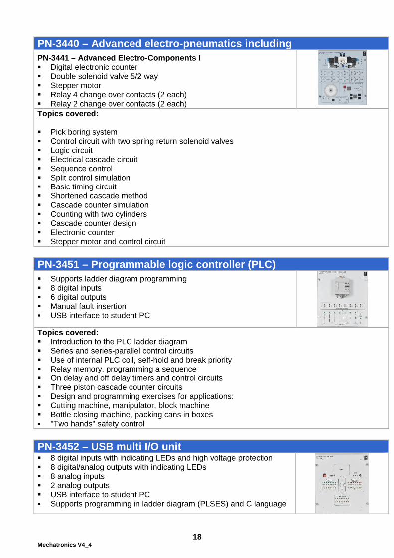
PN-3441 – Advanced Electro-Components I Digital electronic counter Double solenoid valve 5/2 way Stepper motor Relay 4 change over contacts (2 each) Relay 2 change over contacts (2 each) Topics covered: Pick boring system Control circuit with two spring return solenoid valves Logic circuit Electrical cascade circuit Sequence control Split control simulation Basic timing circuit Shortened cascade method Cascade counter simulation Counting with two cylinders Cascade counter design Electronic counter Stepper motor and control circuit PN-3451 – Programmable logic controller (PLC)
Supports ladder diagram programming 8 digital inputs 6 digital outputs Manual fault insertion USB interface to student PC
Topics covered: Introduction to the PLC ladder diagram Series and series-parallel control circuits Use of internal PLC coil, self-hold and break priority Relay memory, programming a sequence On delay and off delay timers and control circuits Three piston cascade counter circuits Design and programming exercises for applications: Cutting machine, manipulator, block machine Bottle closing machine, packing cans in boxes "Two hands" safety control PN-3452 – USB multi I/O unit 8 digital inputs with indicating LEDs and high voltage protection 8 digital/analog outputs with indicating LEDs 8 analog inputs 2 analog outputs USB interface to student PC Supports programming in ladder diagram (PLSES) and C language

19 Mechatronics V4_4
HYD-3500 Hydraulics trainer specifications
The HYD-3500 Hydraulics Trainer, basic unit comprises a compact desktop universal master board (HYD-3501), four sets of industrial hydraulics (HYD-3510, 3520, 3530, 3540) component boards and comprehensive theory and practice manuals. HYD-3501 – Hydraulics master board Size (W x H x D): 575 x 490 x 455 mm 4 rack units External power adaptor 12V power supply 2 pressure gauges 3 hydraulic taps Power switch Hydraulic supply outlets Check valve Adjustable relief valve 12 VDC outlet Oil flow meter device
HYD-3581 – Hydraulic power unit Hydraulic supply section with: Oil tank 9L ON-OFF electrical switch Pressure regulator (20-100 PSI) Pressure relief valve Oil flow 2.2-2.5 L/Min Pressure gauge (0-100 PSI) 1.5 Hp, 1400 RPM

20 Mechatronics V4_4
HYD-3510 – Basic hydraulics including HYD-3511 – Basic hydraulics I Variable flow control needle valve Double acting cylinder Variable flow control valve with check
valve (one way flow-control valve) Single acting cylinder HYD-3512 – Basic hydraulics II 3/2-way spring return valve 4/2-way spring return valve 4/3-way tandem center directional valve HYD-3513 – Basic hydraulics III Pilot check valve Two-way flow control valve Check valve (non-return valve) Adjustable pressure relief valve
Topics covered: Familiarization with the hydraulic power unit and main platform Installation and maintenance of the power unit and main platform Relation between flow rate and pressure Adjustable pressure relief valve to limit pressure Controlling flow direction on 3/2 and 4/2-way valves Two-way compensated flow control valve One-way compensated flow control valve Non-return (check) valve Pilot check valve operation Double acting cylinder in two-way movement application
HYD-3520 – Advanced hydraulics including HYD-3521 – Advanced Hydraulics I Pilot pressure relief valve 3-way flow control valve HYD-3523 – Advanced Hydraulics III Hydraulic accumulator Axial piston hydraulic motor Topics covered: Operation of a differential cylinder Two speed cylinder system Pilot pressure adjustable relief valve Two speed piston stroke Hydraulic motor and control circuit Hydraulic accumulator Testing and adjusting a pressure control valve Testing a 4/3-way tandem valve Testing a double acting cylinder Operating a double acting cylinder with a hydraulic motor Designing a simple hydraulic system

21 Mechatronics V4_4
HYD-3530 – Basic electro-hydraulics including PN-3431 – Basic Electro-Components I Emergency stop push button Pushbuttons (2), 4 contacts: NC (2), 2 NO (2) DPDT switches (2) Relays, 2 change-over contacts (4) Relay, 4 change-over contacts LED indicators (4) Buzzer HYD-3532– Basic Electro-hydraulics II 4/3-way double pilot valve (closed center) 3/2-way spring return solenoid valve HYD-3534– Basic Electro-hydraulics IV 4/2-way valve solenoid – solenoid
Topics covered: Familiarization with the hydraulic power unit Installation and maintenance of the power unit Series connections Series and parallel control The relay as an electrical contact multiplier The relay as an electrical switch The relay as an electrical contact inverter The relay as a memory device with self-holding and break priority Activate a double-acting cylinder with a push button Self-holding relay as a memory device Automatic actuator circuit Step-by-step control of a hydraulic clamp Pressure switch Stop movement of a double-acting cylinder using a push button One-by-one feed system

22 Mechatronics V4_4
HYD-3540 – Advanced electro-hydraulics including HYD-3541 – Advanced Electro-Components I Digital electronic counter Stepper motor Relay 4 change over contacts (2 each) Relay 2 change over contacts (2 each) Topics covered: Pick boring system Control circuit with two spring return solenoid valves Logic circuit Electrical cascade circuit Sequence control Split control simulation Basic timing circuit Shortened cascade method Cascade counter simulation Counting with two cylinders Cascade counter design Electronic counter Stepper motor and control circuit PN-3451 – Programmable logic controller (PLC) Supports ladder diagram programming 8 digital inputs 6 digital outputs Manual fault insertion USB interface to student PC Topics covered: Introduction to the PLC ladder diagram Series and series-parallel control circuits Use of internal PLC coil, self-hold and break priority Relay memory, programming sequence On and off delay timers, control circuits Three piston cascade counter circuits Design and programming exercises for applications: Cutting machine, manipulator, block machine, Bottle closing machine, packing cans. "Two hands" safety control PN-3452 – USB multi I/O unit 8 digital inputs with indicating LEDs and high voltage protection 8 digital/analog outputs with indicating LEDs 8 analog inputs 2 analog outputs USB interface to student PC Supports programming in ladder diagram (PLSES) and C
language

23 Mechatronics V4_4
TP-3714 CNC lathe machine specifications
TP-3714 is a compact, desktop unit designed to introduce the student to the world of the CNC turning machine. The training system exposes the student to the historical development of CNC, to standard G-code and to the use of the computer to control the machine. Through practical, hands-on activities, the unit enables the student to produce milled products with a reasonable degree of accuracy. TP-3714 is a simple maintenance machine that requires only cleaning and lubrication according to the instructions in the user manual.
Technical characteristics: Z axis (110mm) X axis (45mm) Distance between centers –
180mm Spindle speed (500-3000
rpm) Mechanical resolution
±0.1mm Spindle bore (10mm taper
ISO no.1) Spindle motor (DC) Chuck (3 jaws) X and Z axis motors (Stepper
type; 12V DC) Turning diameter (30mm) Transparent door with limit
switch Low voltage LED lighting USB communication to PC Operating voltage (100-240
VAC, 50/60 Hz) General dimensions (650 x
590 x 590 mm) Cabinet for protection against
shavings Emergency stop button Emergency stop by door limit
switch Tail stock for material
Learning program: System description G-code and M-code Installing the D-LATHE
software Operating the system Monitor description Turning processing Arches Turning the rod Project processing Supplied accessories: The learning unit is supplied with the following accessories: 5 Perspex cylinders (100 x
20 mm) 2 Cutting knives (HSS 1/4”) Chuck key Drill for center hole External power supply Allen key set Cleaning brush Software application and
soft copy teacher guide for MS-Windows PC (PC is not included)
Live center USB cable Required accessories: Personal computer with MS
Windows
Safety features: The following safety features are provided by the learning unit: The unit has an 'Emergency
Stop' push button that cuts off all electricity to the unit when pressed.
The door around the spindle and material has limit switches that prevent any operation of the machine when the door is open.
The soft copy teacher guide contains the essential theory and detailed procedures for each hands-on activity.

24 Mechatronics V4_4
TP-3715 CNC milling machine specifications
TP-3715 is a compact, desktop unit designed to introduce the student to the world of the CNC milling machine. The training system exposes the student to the historical development of CNC, to standard G-code and to the use of the computer to control the machine. Through practical, hands-on activities, the unit enables the student to produce milled products with a reasonable degree of accuracy. TP-3715 is a simple maintenance machine that requires only cleaning and lubrication according to the instructions in the user manual.
Technical characteristics: X axis (110mm) Y axis (110mm) Z axis (40mm) Spindle speed (500-3000rpm) Table surface (150 x 230mm) Spindle motor (DC) X, Y and Z axis motors
(Stepper type; 12 VDC) Spindle bore (10mm, Morse
taper no. 1) Emergency stop button Low voltage LED lighting USB communication to PC Operating voltage (110-240
VAC external switching supply)
General dimensions (650 x 590 x 590mm)
Learning program: System description G code and M code Operating the DMILL
software Operating the entire system Monitor description Slot processing Arches Profile processing Pocket processing Drill processing Project processing Supplied accessories: The learning unit is supplied with the following accessories: 5 plastic blocks, 90 x 80 x
20mm Milling tool, 3mm Milling tool, 6mm Key-type drill chuck MT 1-
3/8-24 (assembled) Drill chuck arbor MT 1-3/8-24
UNF (assembled) External power supply Cleaning brush Software application and soft
copy teacher guide for MS-Windows PC (PC is not included)
USB cable Required accessories: Personal computer with MS
Windows
Safety features: The following safety features are provided by the learning unit: The unit has an 'Emergency
Stop' push button that cuts off all electricity to the unit when pressed.
The door around the spindle and material has limit switches that prevent any operation of the machine when the door is open.
The soft copy teacher guide contains the essential theory and detailed procedures for each hands-on activity.

SES Training LABs
The training labs are based on learning-by-doing, which makes the students learn more quickly and remember what they have studied by performing practical experiments. They provide the students high profession skills and the knowledge on how to improve their chance of employment and earning capacity. The manuals and courseware that accompany each course provide the theory background and experiments. Electronics Training Lab This modular laboratory is aimed for the Electronics profession, but also for technology disciplines that are also based in electronics, such as: Electricity, Mechanics, Automotive, Robotics, Automation, Process control. Autotronics Training Lab This modular laboratory is aimed for the five stages that comprise the automotive program: Basic and automotive electronics, Car sub-systems simulators, Car sub-systems demonstrators, Car diagnostic and troubleshooting methods, Troubleshooting faults in a real car. Mechatronics Training Lab This modular laboratory is aimed for the mechatronics program which includes the following disciplines: Basic electronics, Pneumatics systems, Hydraulics systems, CNC machines. Refrigeration and Air-Conditioning Training Lab The Refrigeration and Air-Conditioning training lab covers actual components and their interconnection, related functions, operation, diagnosis and repair methods through safe, hands-on practical activities. Technology Preparation Training Lab The Technology Preparation (Tech Prep) laboratory is a classroom-integrated laboratory consisting of educational modules covering a wide range of subjects such as: Green energy, Computerized systems, Basic electronics, Basic communication, Mechanical systems. Science Training Labs These laboratories (for primary, secondary and high schools) introduce the students to the computerized sensors world, nature and industry processes and nature laws. It will help them understand modern technologies such as: home and medical appliances, wearing sensors, precise agriculture and more. Robotics Training Labs The robotics programs (for primary, secondary and high schools) help students to build innovation and creativity skills. The idea is to make the students understand how systems work, to believe that they can improve them and be able to realize their ideas. MultiCenter Training Lab The MultiCenter offers a variety of selected interactive learning environments, with a large range of topics and activities such as: Science, Technology, Graphic Design, Digital Music, Robotics, Computer Technologies and much more for all sectors of society, cultures, different socio-economic groups and different age groups – from very young children to senior citizens.

Our Training Labs:
SCIENCE
ROBOTICS
ELECTRONICS
ELECTRICITY
TELECOMMUINCATION
AUTOTRONICS
MECHATRONICS
MULTICENTER
SCIENCE & ROBOTICS
TECHNOLOGY PREPARATION
REFRIGIRATION & AIR-CONDITIONING
MEC
HA
TRO
NIC
S